

Page 1
Programmable Display
GT Series
Technical Manual
Applicable Product
• GT01
• GT11
• GT30
http://www.naisplc.com/
This manual was created using Adobe Acrobat.
Adobe, the Adobe logo, and Acrobat are trademarks
of Adobe Systems Incorporated.
GT Series Technical Manual
ARCT1F398E ’04.11
Page 2

Page 3

Table of contents
Before You Start----------------------------------------------------------------------------------------------------------------ⅰⅰⅰⅰ
Usage Procedures-------------------------------------------------------------------------------------------------------------ⅲⅲⅲⅲ
Confirming the Package Contens----------------------------------------------------------------------------------------ⅳⅳⅳⅳ
GT series System Configuration (GT01 and GT11)-----------------------------------------------------------------ⅸⅸⅸⅸ
GT series System Configuration (GT30)-------------------------------------------------------------------------------ⅹⅹⅹⅹ
Products Types and Manuals-------------------------------------------------------------------------------------------ⅹⅰ
An overview of GT Series Functions---------------------------------------------------------------------------------ⅹⅲ
ⅹⅰ
ⅹⅰⅹⅰ
ⅹⅲ
ⅹⅲⅹⅲ
1 Specifications 1-1
1.1 GT01 Specifications 1-2
1.1.1 General Specifications 1-2
1.1.2 Display 1-2
1.1.3 Functions 1-3
1.1.4 Touch Key 1-3
1.1.5 Memory 1-3
1.1.6 Serial Interface 1-4
1.2 GT11 Specifications 1-5
1.2.1 General Specifications 1-5
1.2.2 Display 1-5
1.2.3 Functions 1-6
1.2.4 Touch Key 1-6
1.2.5 Memory 1-6
1.2.6 Serial Interface 1-7
1.3 GT30 Specifications 1-8
1.3.1 General Specifications 1-8
1.3.2 Display 1-8
1.3.3 Functions 1-9
1.3.4 Touch Key 1-9
1.3.5 Memory 1-9
1.3.6 Serial Interface 1-10
1.4 Names and Functions of Parts 1-11
1.4.1 GT01 and GT11 1-11
1.4.2 GT30 1-14
1.5 Internal Wiring Connections for Ports 1-16
1.5.1 COM. Port (GT01) 1-16
1.5.2 COM. Port (GT11) 1-18
1.5.3 COM. Port (GT30) 1-19
1.5.4 TOOL Port 1-19
1.6 Dimensions 1-20
1.6.1 GT01 1-20
1.6.2 GT11 1-21
1.6.3 GT30 1-22
Page 4

2 Installation and Wiring 2-1
2.1 Installation 2-2
2.1.1 Installation Environment 2-2
2.1.2 GT01 and GT11 Installation Method 2-3
2.1.3 GT30 Installation Method 2-4
2.2 Wiring the Power Supply 2-5
2.2.1 Wiring the Power supply 2-5
2.2.2 Grounding 2-6
2.3 Wiring the COM. Port 2-7
3 Setup 3-1
3.1 Setup Procedure for the GT 3-2
3.2 Setting the Basic Communication Area Between the GT and PLC 3-4
3.2.1 What is the Basic Communication Area? 3-4
3.2.2 Settings in GTWIN 3-5
3.2.3 GT01 Basic Communication Area Map 3-6
3.2.4 GT11 Basic Communication Area Map 3-7
3.2.5 GT30 Basic Communication Area Map 3-8
4 Connecting and Communicating with the PLC 4-1
4.1 Connecting GT01/GT11 with PLC 4-2
4.1.1 Connecting to the TOOL port of FPΣ / FP0 / FP-e (1) (Direct Connection to GT01) 4-2
4.1.2 Connecting to the TOOL port of FPΣ / FP0 / FP-e (2) 4-3
4.1.3 Connecting to the TOOL port of FP2 / FP2SH (1) (Direct Connection to GT01) 4-4
4.1.4 Connecting to the TOOL port of FP2 / FP2SH (2) 4-5
4.1.5 Connecting to the TOOL port of FP10SH (1) (Direct Connection to GT01) 4-6
4.1.6 Connecting to the TOOL port of FP10SH (2) 4-7
4.1.7 Connecting to the TOOL port of FP-M (1) (Direct Connection to GT01) 4-8
4.1.8 Connecting to the TOOL port of FP-M (2) 4-9
4.1.9 Connecting to the COM. port of FPΣ / FP0 / FP-e 4-10
4.1.10 Connecting to the COM port of FP1 / FP2SH / FP-M 4-12
4.1.11 Connecting to the COM port of FP10SH 4-13
4.1.12 Connecting to the FP2 / FP2SH Computer Communication Unit 4-14
4.1.13 Connecting to the FP10SH / FP3 Computer Communication Unit 4-15
4.1.14 Cautions Regarding Direct Connection of GT01 (5V DC type) to the FP Series TOOL
Port 4-16
4.1.15 How to Make Communication Settings Using the FPWIN GR and FPWIN Pro 4-17
4.1.16 Automatic Communication Settings Function 4-19
4.1.17 Through Function 4-20
4.1.18 Connecting a PLC by Mitsubishi Electric Corporation 4-21
4.1.19 Connecitng the PROVISER Tcmini Series by Toshiba Machine Co., Ltd. 4-27
4.1.20 Connecitng the S7-200 Series by Siemens K. K. 4-28
4.1.21 Connecitng a PLC by Modicon 4-29
4.1.22 Connecting PLCs by Omron Corporation 4-30
4.1.23 Connecting a PLC by Yokogawa Electric Corporation 4-37
Page 5

4.1.24 Connecting a Sereial Device 4-39
4.2 Connecting GT30 with PLC 4-40
4.2.1 Connecting to the FPΣ 4-40
4.2.2 Connecting to the FP0 4-42
4.2.3 Connecting to the FP1 4-44
4.2.4 Connecting to the FP2/FP2SH 4-45
4.2.5 Connecting to the FP2/FP2SH Computer Communication Unit 4-47
4.2.6 Connecting to the FP10SH 4-48
4.2.7 Connecting to the FP10SH/FP3 Computer Communication Unit 4-50
4.2.8 Connecting to the FP-M 4-51
4.2.9 Atutomatic Communication Settings Function 4-53
4.2.10 Through Function 4-54
4.2.11 Connecitng a PLC by Mitsubishi Electric Corporation 4-55
4.2.12 Connecting PLCs by Omron Corporation 4-56
4.2.13 Connecting a PLC by Yokogawa Electric Corporation 4-62
5 GT Configuration Settings 5-1
5.1 GT Configuration Settings 5-2
5.2 Entering Configuration Settings from GTWIN Screen Creation Tool 5-3
5.2.1 GT Configuration Settings: “Basic Setup” 5-3
5.2.2 GT Configuration Settings: “Communication Parameters” 5-6
5.2.3 GT Configuration Settings: “Auto-Paging” 5-8
5.2.4 GT Configuration Settings: “Startup Screen Settings” 5-9
5.2.5 GT Configuration Settings: “Setup” (For GT01) 5-10
5.2.6 GT Configuration Settings: “Setup” (For GT11) 5-12
5.2.7 GT Configuration Settings: “Setup” (For GT30) 5-15
5.2.8 GT Configuration Settings: “Hold Device Value” 5-18
5.3 Entering Configuration Settings from the GT01 and GT11 Main Unit 5-20
5.3.1 Bringing Up the System Menu 5-20
5.3.2 Setting Mode: “Communication Parameters” (COM. Port / TOOL Port) 5-21
5.3.3 Setting Mode: “Liquid Crystal Display Contrast Adjustment” (Contrast) 5-23
5.3.4 Setting Mode: “Memory Initialization” (Clear Memory) 5-24
5.3.5 Setting Mode: “Touch Switch Adjustment” (T. SW) 5-25
5.3.6 Setting Mode: “Self-Diagnosis” (Test Mode) 5-26
5.3.7 Inhibiting the System Menu Display 5-27
5.4 Entering Configuration Settings from the GT30 Main Unit 5-28
5.4.1 Bringing Up the System Menu 5-28
5.4.2 Setting Mode: “Liquid Crystal Display Contrast Adjustment” (Contrast) 5-29
5.4.3 Setting Mode: “Clock Settings” (Clock) 5-30
5.4.4 Setting Mode: “Communication Parameters” (TOOL Port / COM. Port) 5-31
5.4.5 Setting Mode: “Memory Initialization” (Clear Memory) 5-33
5.4.6 Setting Mode: “Self-Diagnosis” (Test Menu) 5-34
5.4.7 Inhibiting the System Menu Display 5-35
Page 6

6 How the Various Functions Are Used 6-1
6.1 Switching Screens 6-2
6.1.1 Switching the Screen from the PLC 6-2
6.1.2 Switching the Screen with the GT Main Unit 6-3
6.2 Basic Communication Area to PLC and Bit Device Functions (GT01) 6-6
6.3 Basic Communication Area to PLC and Bit Device Functions (GT11) 6-7
6.4 Basic Communication Area to PLC and Bit Device Functions (GT30) 6-9
7 Servicing and Maintenance 7-1
7.1 What the Battery Does (GT11) 7-2
7.2 What the Battery Does (GT30) 7-3
7.3 About the Front Panel Protective Sheet 7-4
7.4 About the Waterproof Packing 7-5
7.5 Replacing the Backlight (Sold Separately) (Applies Only to GT30) 7-6
8 Troubleshooting 8-1
8.1 What to DO If Something Unusual Occurs (GT01 & GT11) 8-2
8.2 What to DO If Something Unusual Occurs (GT30) 8-5
8.3 Error Codes and How to Handle Them 8-8
8.3.1 About Error Codes 8-8
8.3.2 GT Weries Error Codes 8-8
8.3.3 When Connected to a FP Series PLC 8-9
8.3.4 When Connected to a PLC (FX Series) Made by Mitsubishi Electric Corporation 8-10
8.3.5 When Connected to a PLC Made by Omron Corporation 8-10
8.4 Table of Screen Messages 8-11
9 Documentation 9-1
9.1 BIN/HEX/BCD Code Correspondence Table 9-2
9.2 ASCII Code Table 9-3
9.3 Cable Specifications 9-4
9.3.1 FP series TOOL Port Connection Cable: Mini-DIN 5-pin Loose Wire (AIGT8142) 9-4
9.3.2 Mitsubishi Electric FX series TOOL Port Communication Cable (AIGT8152) 9-4
9.3.3 PLC Communication Cable: Mini-DIN 5-pin Loose Wire (AIGT816*) 9-4
9.3.4 PLC Communication Cable: Mini-DIN 8-pin Loose Wire (AIGT8175) 9-5
Page 7

9.3.5 PLC Communication Cable: D-SUB 9-pin Loose Wire (AIP81842) 9-5
9.3.6 PLC Communication Cable: Mini-DIN 5-pin Loose Wire (AIGT8192) 9-5
9.4 Summary of Features and Compatible Versions 9-6
10 Terminal GTWIN 10-1
10.1 Precautions Before Using GTWIN 10-2
10.1.1 Special Precautions 10-3
10.2 Installing GTWIN 10-4
10.3 Booting GTWIN 10-8
10.4 Exiting GTWIN 10-9
10.5 Procedures for Using GTWIN 10-10
Page 8

Before You Start
Usage conditions
When installing the product, make sure it is used within the range of the general specifications. Do not
use in the following environments:
• Areas whwere the unit may come in contact with water (the unit is warranted by IP65 for the installed
panel, but this applies to initial values and operation cannot be guaranteed in areas where the unit is
constantly subjected to water or to extreme temperature or humidity.)
• Areas where the ambient temperature exceeds the range 0 to 50 °C.
• Areas where the ambient humidity exceeds 20 to 85% RH (at 25 °C non-condensing).
• If the control panel and other parts are installed in an environment where the air tends to be poorly
ventilated, forced cooling should be used to keep the ambient temperature of the from going over 50 °C.
This prevents the temperature of the GT main unit from rising.
• Locations where condensation may form because of sudden fluctuations in temperature.
• Locations where flammable or corrosive gases are present.
• Locations where there are high concentrations of dust or iron filings.
• Locations where substances such as organic solvents (thinner, benzene, etc.) or strong alkali
substances (ammonia, caustic soda, etc.) might adhere to the product.
• Locations where the product is subject to extreme vibration and/or impact.
• Avoid installing the product near high-voltage lines, high-voltage devices, power lines, power devices,
amateur radio sets and other transmitters, and devices that generate strong current surges.
• Avoid locations where the display unit is subject to direct sunlight.
Safety precautions
The switch functions of the programmable display unit should not be used to design systems which may
pose a threat to human life or which may cause severe injury or damage. Designs should include safety
mechanisms for use in the event that switch functions do not function correctly.
Power supply wiring
• For the power supply, use twisted wire (strand wire).
• There is sufficient noise resistance to offset power line noise, but we recommend reducing noise by
measures such as installing an insulated transformer.
• Separate wiring systems should be used for the power supply unit and the operating unit.
Static Electricity/Noise
• Keep the GT main unit, PLC connecting cable, and other wiring as far away as possible from
machines which are likely to produce noise (welding equipment, power lines, inverters, motors, etc.)
• For use in environments where the frequent occurrence of static electricity, radiation, or induced noise
can be expected, the use of shielded cable on all wiring and grounding of shield (1-point ground) is
recommended. When wiring the equipment, shielded wires should be electrically insulated to signal
lines and signal grounds.
• If excessive static electricity is applied to the panel surface, the LCD display unit may be damaged.
i
Page 9

Other precautions
• Do not connect any devices other than our Programmer II to the TOOL port.
• Always operate the touch panel with fingers as the touch panel may be damaged due to the excessive
load or shock (caused when being operated with any tools). Also, if the touch panel is pressed like
kneading, the electrode may be worn out exceptionally, and cause the malfunction. Operate with a
single touch of the panel.
• Do not disassemble, reassemble or remodel the GT main unit as we cannot assure the performance if
you have done such things.
Battery
Do not leave the battery in the unit when it is not used. There is a possibility of leak if it is left being
discharged.
ii
Page 10

Usage Procedures
If you are using the GT series for the first time, please follow the procedure outlined below.
1. Confirm the items included with the product. Next page
Please confirm that all of the items have been included with the product you have purchased. Products
are carefully checked before being shipped, but if you do find anything missing, please contact your
dealer.
2. Install and wire the main unit. Chapter 2
Install the main unit, and connect the power supply, PLC connection cable and other wiring.
For information on connecting the product to the FP series PLC, and on entering communications
settings,
Reference: <Chapter 4 Connecting and Communicating with the PLC>
3. Set up the main unit. Chapter 3
When the product is shipped from the factory, it is set up with specifications that enable connection to
the FP series PLC. If you plan to use the product without changing these settings, no setup is required,
but if you plan to change the settings, you will need to follow the setup procedure. Particularly with
regard to the basic communication area to the PLC and other devices, please confirm the settings
carefully and change only those that are necessary.
Main cases in which setup is necessary
• When the device being connected is a general-purpose serial device (such as a computer or
microcomputer board).
• When the basic communication area for the device is different from that set when the product is
shipped.
4. Check communication with the external device (PLC, etc.). Chapter 4
Check the connections and communication with the external device. Connections and communication
with devices in the FP series PLC vary depending on the device.
5. Enter the operating environment settings Chapter 5
In addition to the setup described at step 4, various detailed settings can be entered from the GT main
unit operating environment.
6. Install the screen creation tool.
Install the Terminal GTWIN screen creation tool in the personal computer.
7. Create the screen contents.
Create the screen contents using the Terminal GTWIN screen creation tool, and send the screen to the
GT main unit. For information on creating screens and on operating GTWIN, please refer to the HELP
function that comes with GTWIN.
8. Test the operation.
Connect the GT main unit containing the screen data to an external device (PLC or general-purpose
serial device), and check the operation contents.
iii
Page 11
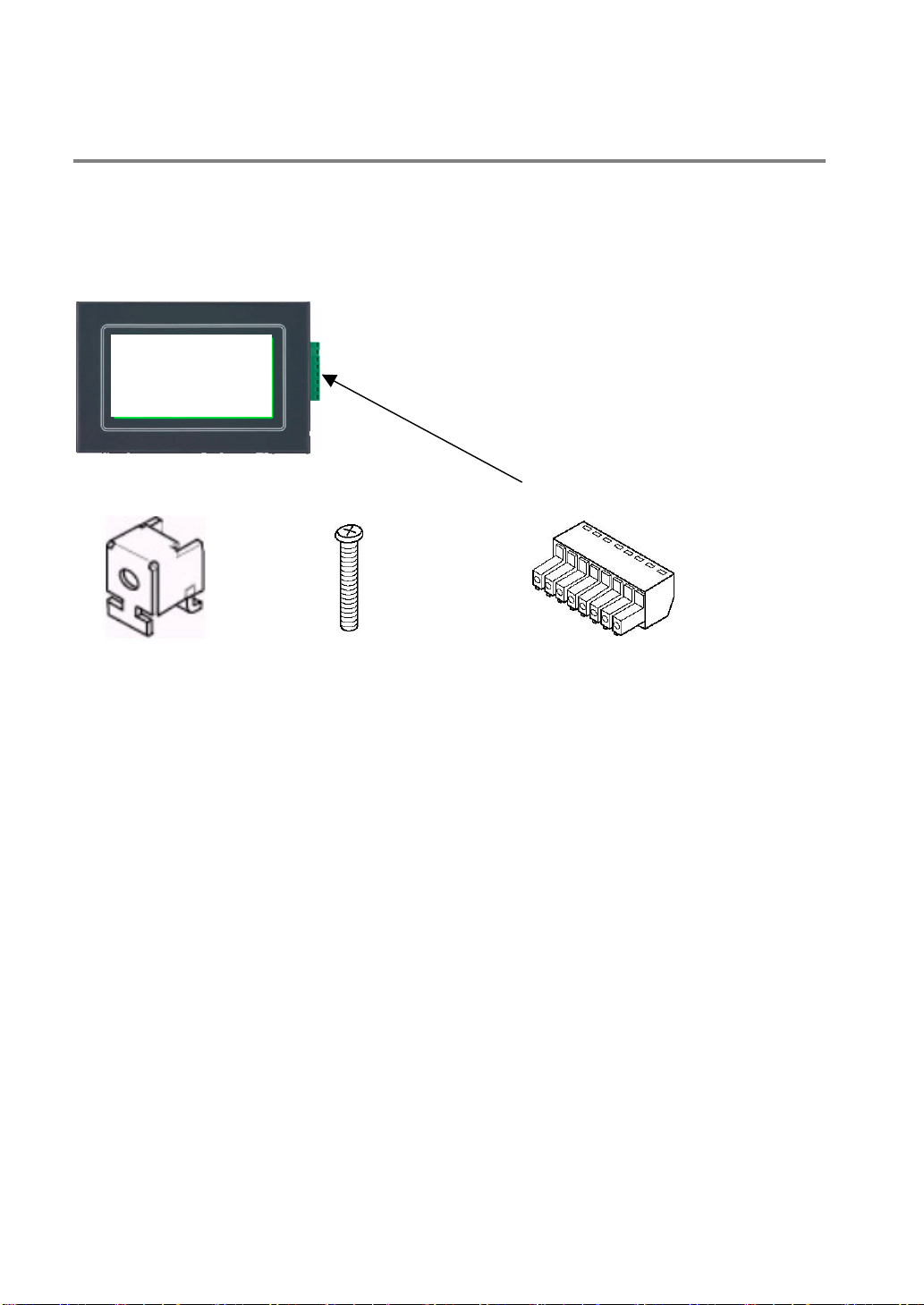
Confirming the Package Contents
Check to make sure the necessary items have been included with the product you have purchased.
Items included with the GT01
Main unit (Photo is AIGT0030B1)
Set of attachment fittings Connector for communications (x1)
Attachment fittings x 4 Attachment screws x 4
Repair parts are available.
AIGT083 (contains 5 sets.)
* 4 pcs of attachment fittings and 4 pcs of
attachment screws are contained in one set.
Repair parts are available.
AIGT084 (contains 5 pcs.)
Installation instructions
Please read these instructions carefully before
using the product.
◯1 There is a film over the front panel protective sheet. Remove this film when using the unit
2
◯
Front panel protective sheets for replacement are available as a separate purchase AIGT080 (10
sheet set).
Waterproof packing
One piece of waterproof packing has been
attached to unit.
The following maintenance part is available:
AIGT081 (10 piece set)
iv
Page 12
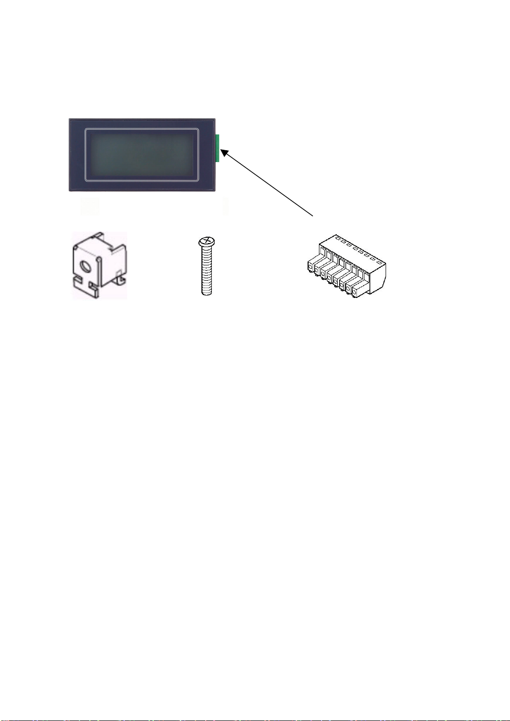
Items included with the GT11
Main unit (Photo is AIGT2030B)
Set of attachment fittings Connector for communications (x1)
Attachment fittings x 4 Attachment screws x 4
Repair parts are available.
AIGT084 (contains 5 pcs.)
Repair parts are available.
AIGT083 (contains 5 sets.)
* 4 pcs of attachment fittings and 4 pcs of
attachment screws are contained in one set.
Installation instructions
Please read these instructions carefully before
using the product.
Waterproof packing
One piece of waterproof packing has been
attached to unit.
The following maintenance part is available:
AIGT181 (10 piece set)
◯1 There is a film over the front panel protective sheet. Remove this film when using the unit
2
◯
Front panel protective sheets for replacement are available as a separate purchase AIGT280 (10
sheet set).
v
Page 13
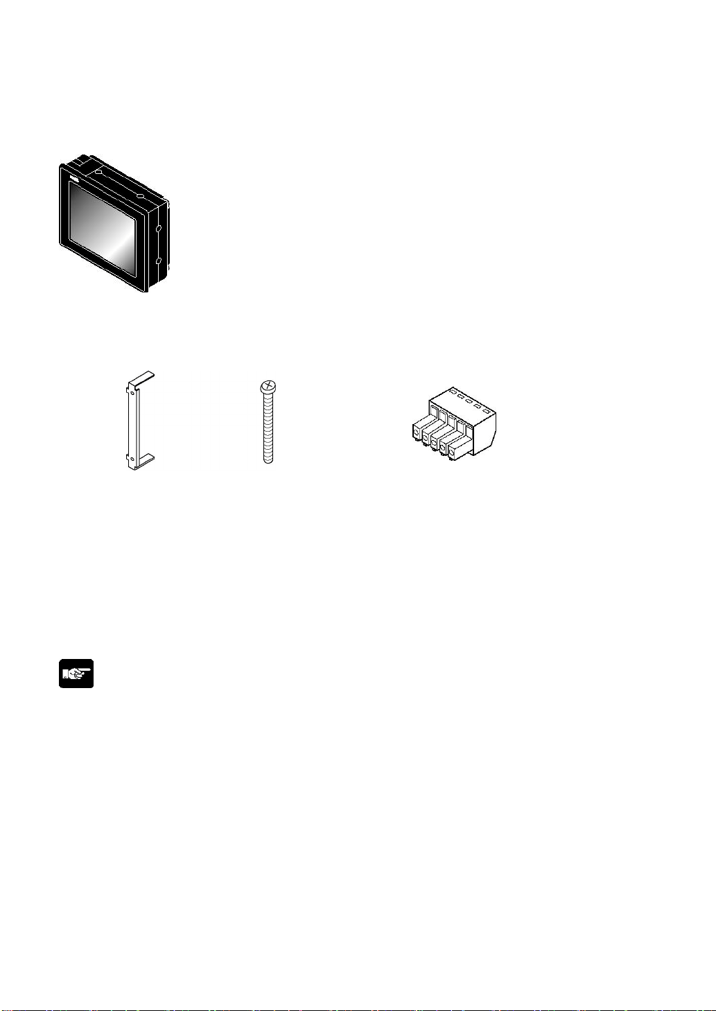
Items included with the GT30 (AIGT3100B and AIGT3300B)
Main unit
STN monochrome liquid crystal display type: AIGT3100B
STN color liquid crystal display type: AIGT3300B
Set of attachment fittings Connector for communications (x1)
Fittings x 2 Screws x 4
Front panel protective sheet
There is a front panel protective sheet, available as
an optional product, attached to the front panel of
the unit.
Installation instructions
Please read these instructions carefully before
using the product.
Note:
• There is a film over the front panel protective sheet. Remove this film when using the unit.
• Front panel protective sheets for replacement are available as a separate purchase (AIGT380).
• Waterproof packings for replacement are available as a separate purchase (AIGT381).
• A replacement backlight is available as a separate purchase (AIGT382).
• The commercially available CR2032 should be used for battery replacement.
Waterproof packing
One piece of waterproof packing has been
attached to unit.
vi
Page 14
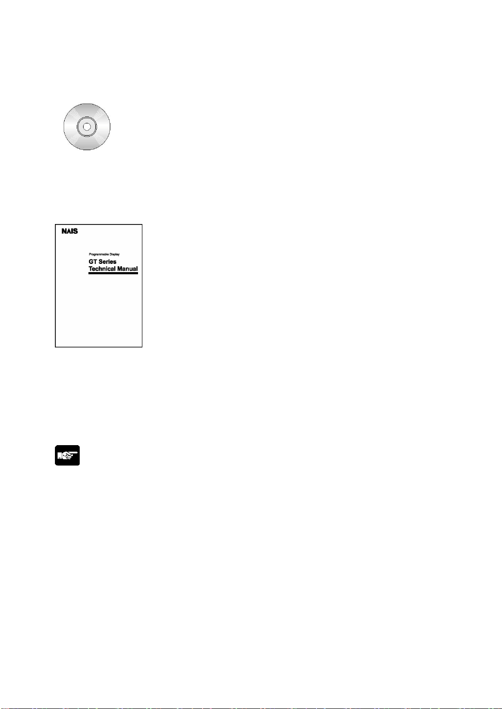
Items included with the Terminal GTWIN English-language version (AIGT8001V2)
Terminal GTWIN CD-ROM
Software usage license agreement and user card
Read the “Software usage license agreement” carefully, and fill in the user card. Please return the user
card to Matsushita.
GT series Technical Manual
ARCT1F398E
This is the manual you are currently reading. It contains instructions on installing and booting GTWIN.
Please read it carefully before using your product.
About the manual for the screen creation software tool
The GT Series Technical Manual provides an installation guide. However, for detailed operation
procedures please use the help function. The Terminal GTWIN Operational Guide Book (ARCT1F357E),
which covers basic operation, is also available. Please contact us if you would like a copy.
Note:
About the software usage license agreement and user card
• Before using GTWIN, readthe “Software usage license agreement” carefully.
• The license agreement comes as a set with the user card. Fill in the user card, and return it to
Matsushita. The user card is necessary in order to obtain support services such as future version
upgrades and technical support. Don’t forget to return the card in order to be eligible for such services.
• The serial number needed in order to install GTWIN is found on the user card. Please make a copy of
it before returning the card, and keep it in a safe place.
vii
Page 15
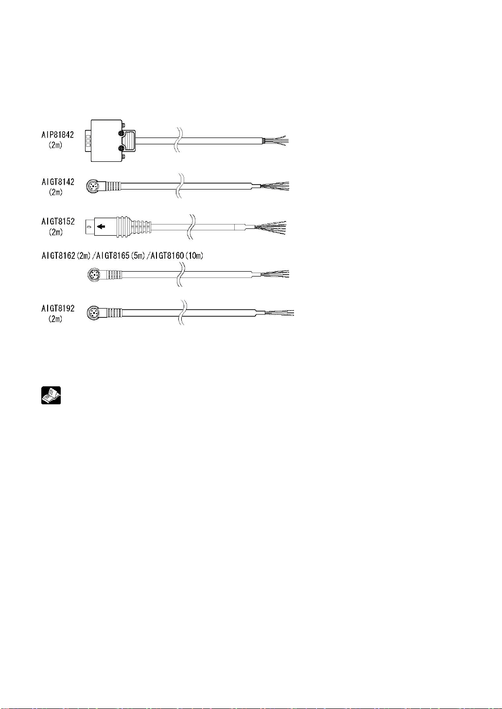
Items included with the PLC conncation cable (AIP81842/AIGT8142/AIGT8152/AIGT8162)
Cable
One of the following cables has been included with the product you have purchased.
Wiring diagram
The package includes a diagram that shows the internal wiring of the cables pictured above. AIGT816* is
only a RS232C cable and is for use when the GT01 is using separate power supply or for GT11.
Reference:
For information on connecting and wiring the cables shown above and the PLC, refer to <Chapter 4
Connecting and Communicating with the PLC”.
viii
Page 16
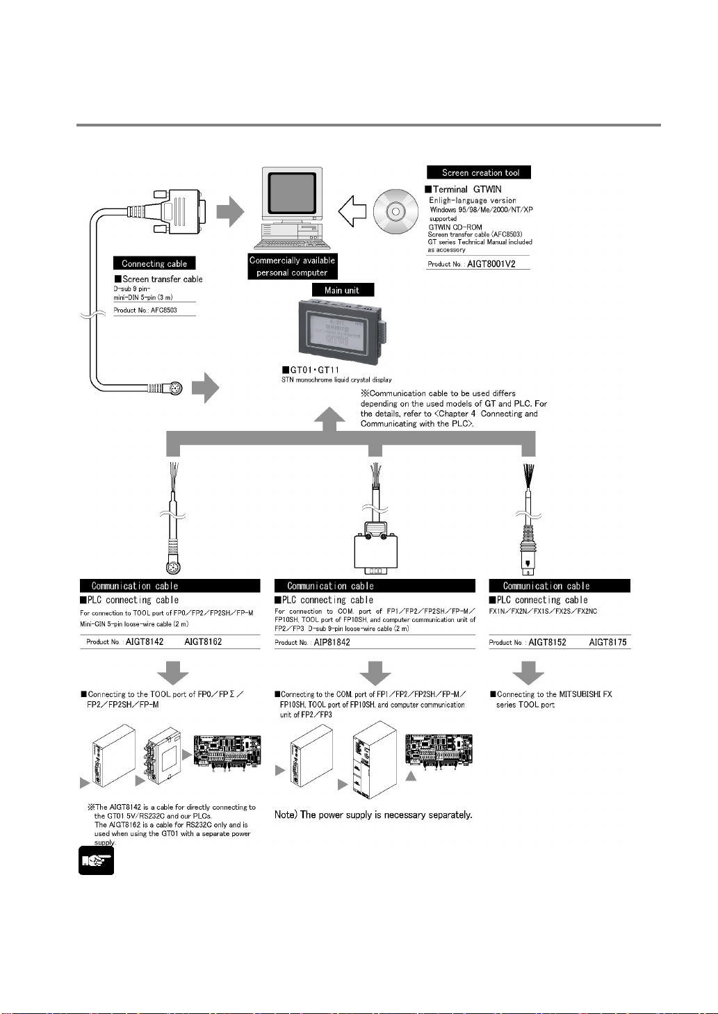
GT Series System Configuration (GT01 and GT11)
The following devices are necessary in order to use the GT series.
Note:
Connecting to the COM. port of the PLC
Because connecting the unit to the COM. port of the FPΣ/FP0 requires a loose-wire connection, this
cable is not available.
ix
Page 17
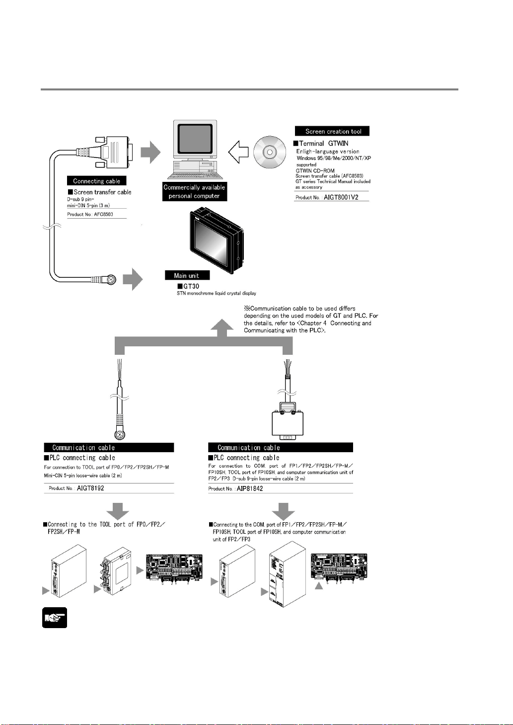
GT Series System Configuration (GT30)
The following devices are necessary in order to use the GT series.
Note:
Connecting to the COM. port of the PLC
Because connecting the unit to the COM. port of the FPΣ/FP0 requires a loose-wire connection, this
cable is not available.
x
Page 18
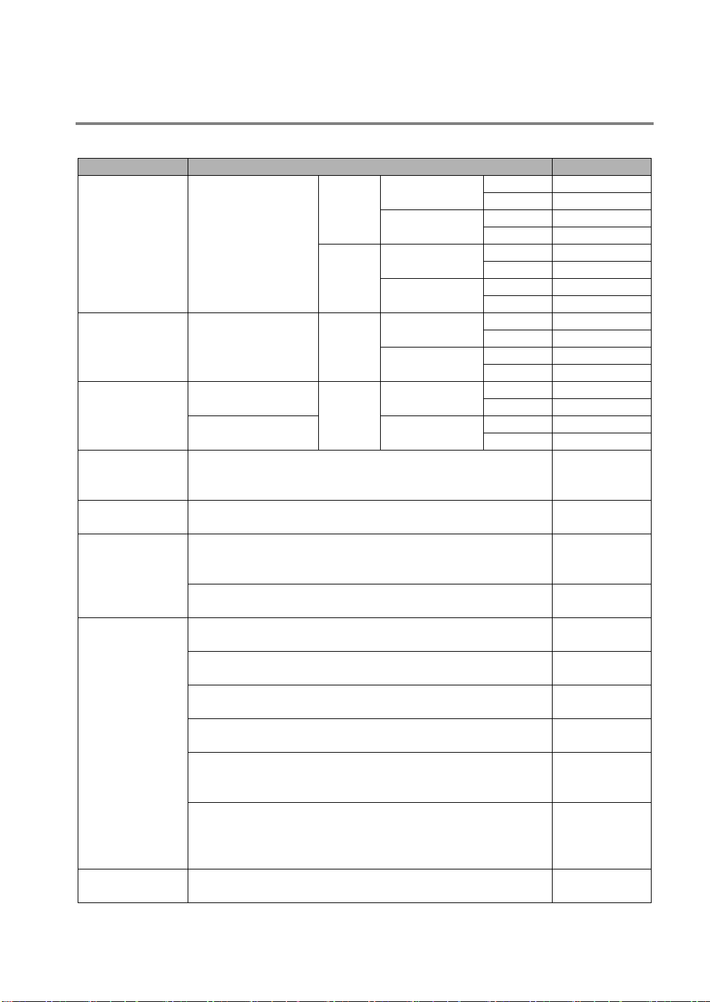
Products Types and Manuals
Products types for the GT series
Item name Contents Product No.
Black AIGT0030B1
Ashgray AIGT0030H1
Black AIGT0032B1
Ashgray AIGT0032H1
Black AIGT0030B
Ashgray AIGT0030H
Black AIGT0032B
Ashgray AIGT0032H
Black AIGT2030B
Ashgray AIGT2030H
Black AIGT2032B
Ashgray AIGT2032H
Black AIGT3100B
Ashgray AIGT3100H
Black AIGT3300B
Ashgray AIGT3300H
AIGT8001V2
AIGT8142
AIGT8152
AIGT8162
AIGT8165
AIGT8160
AIGT8175
AIGT8192
AIP81842
GT01 main unit
GT11 main unit
GT30 main unit
Terminal GTWIN
Ver. 2 Englishlanguage version
Terminal GTWIN
upgrade version
PLC direct
cables
PLC connecting
cables
Screen transfer
cable
RS232C type
5V DC
STN monochrome
liquid crystal display
24V DC
STN monochrome
liquid crystal display
STN monochrome
liquid crystal display
STN color liquid
crystal displa
- “Terminal GTWIN” English-language screen creation tool (CDROM)
- Set of GT series Hardware Manuals
Upgrade “Terminal GTWIN” screen creation tool Ver. 1 to Ver. 2 AIGT8001V2R
For direct connection to GT01 (5V DC/RS232C) and TOOL port
of PLCs (FP-3/FP0/FPΣ/FP2/FP2SH/FP-M). Mini-DIN 5-pin
(2 m)
For direction connection to GT01 (5V DC/RS422) and
MITSUBISHI FX series. Mini-DIN 8-pin (2 m)
For connection to GT01 (24V DC), GT11 and PLCs. Mini-DIN 5pin loose-wire cable (2 m)
For connection to GT01 (24V DC), GT11 and PLCs. Mini-DIN 5pin loose-wire cable (5 m)
For connection to GT01 (24V DC), GT11 and PLCs. Mini-DIN 5pin loose-wire cable (10 m)
For connection to GT01 (24V DC), GT11 and Mitsubishi FX
series. Mini-DIN 8-pin loose-wire cable (5 m)
For connection to GT10, GT30 and TOOL port of PLCs (FP3/FP0/FPΣ/FP2/FP2SH/FP-M). Mini-DIN 8-pin loose-wire cable
(2 m)
For connection to COM. port of FP1/FP2/FP2SH/FPM/FP10SH, TOOL port of FP10SH, and computer
communication unit of FP2/FP3. D-SUB 9-pin loose-wire cable
(2 m)
Screen data transfer caable for GTWIN and GT series AFC8503
y
24V DC
24V DC
RS422/RS485
type
RS232C type
RS422/RS485
type
RS232C type
RS422/RS485
type
RS232C type
RS232C type
xi
Page 19
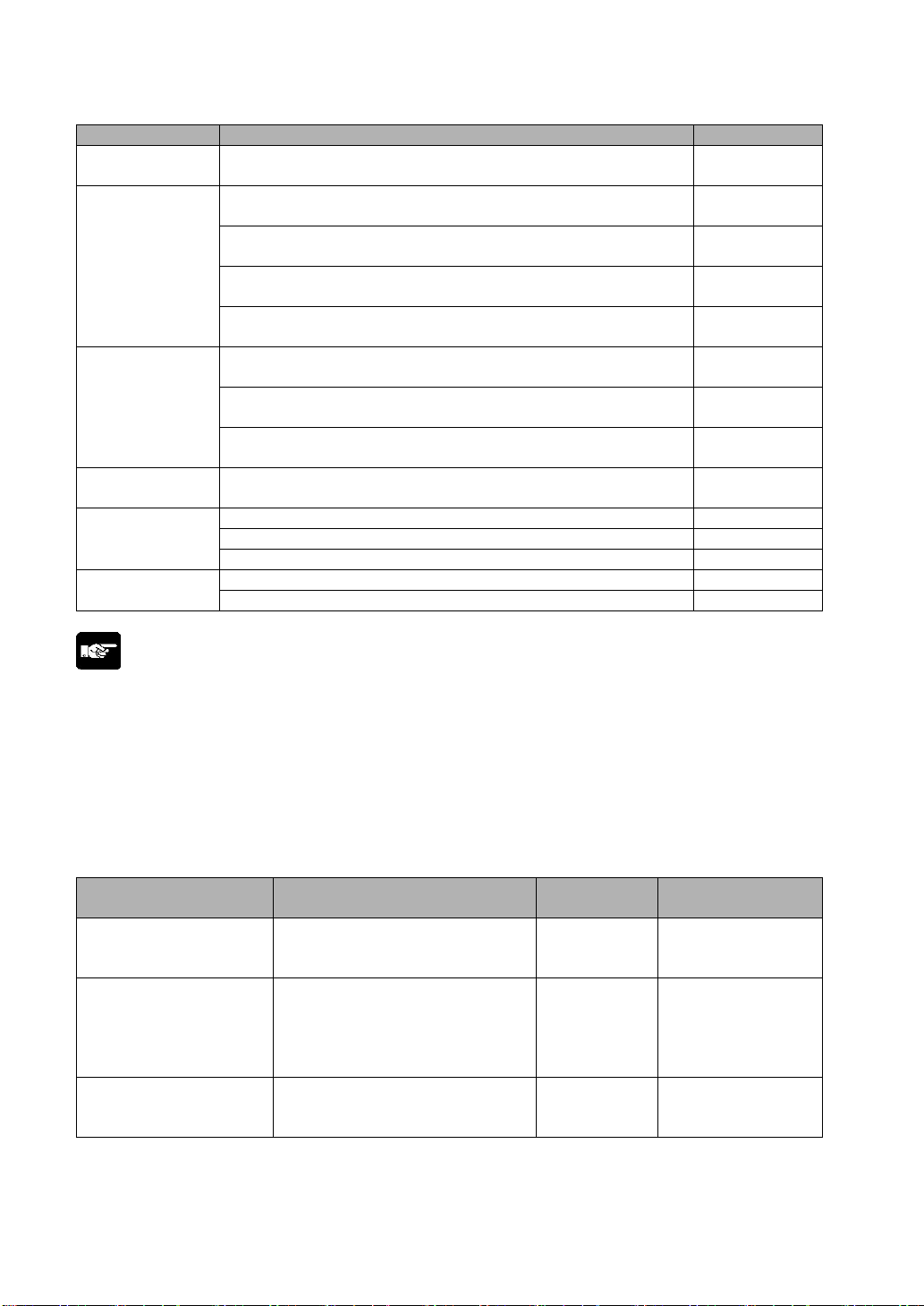
Item name Contents Product No.
Screen transfer
cable
Front panel
protective sheet
Waterproof
packing
Replacement
backlight
Attachment
fittings
Connector
Screen data transfer caable for GTWIN and GT series. Mini-DIN
5-pin straight type
Front panel protective sheet for GT01. 10 in set. (sold
separately)
Front panel protective sheet for GT11. 10 in set. (sold
separately)
Front panel protective sheet for GT10 (for replacement). 10 in
set. * 1 sheet included with the main unit when shipped.
Front panel protective sheet for GT30 (for replacement). 10 in
set. * 1 sheet included with the main unit when shipped.
Waterproof packing for GT01 ( for replacement). 10 in set.
* 1 sheet included with the main unit when shipped.
Waterproof packing for GT10/GT11 ( for replacement). 10 in
set. * 1 sheet included with the main unit when shipped.
Waterproof packing for GT30 ( for replacement). 10 in set.
* 1 sheet included with the main unit when shipped.
This is the replacement backlight for the GT30
color/monochrome liquid crystal display.
AFC8503S
AIGT080
AIGT280
AIGT180
AIGT380
AIGT081
AIGT181
AIGT381
AIGT382
Attachment fittings for GT01/GT11. 5 set (4 pcs./set) AIGT083
Attachment fittings for GT10. 5 set (4 pcs./set) AIGT183
Attachment fittings for GT30. 5 set (2 pcs./set) AIGT383
COM port connector for GT01/GT11. 5 set AIGT084
COM port connector for GT10/GT30. 5 set AIGT184
Note:
• Connecting to the COM. port of the FP0
Because connecting the unit to the COM. port of the FPΣ/FP0 requires a loose-wire connection, this
cable is not available.
• The AIGT8142 is a cable for directly connecting to the 5 V type GT01 and the FP series TOOL port.
(Power can be supplied from the FP series.)
• The AIGT8162, AIGT8165 and AIGT8160 is the cables for connecting the GT01 (24V DC, RS232C),
GT11 and the TOOL port of our PLCs.
• The AIGT8192 is a cable for connecting the GT30 and the TOOL port of our PLCs.
Types of manuals
Manual name Contents
Terminal GTWIN
Operational Guide
Note1)
Book
Explains basic screen creation
methods.
Manual
number
ARCT1F357E No
Manual included
in GTWIN
Explains about protocols and
GT Multi-purpose
Serial Communications
Manual
handling when controlling the GT
Series using communicating from
an external device such as PC
ARCT1F356E No
board.
GT series Technical
Manual
Note2)
Explains about the hardware
specifications and handling
procedures.
ARCT1F398E Yes
Note1) Only covers basic operation. Please use the help function for detailed operation procedures.
Note2) Contains a GTWIN installation guide.
xii
Page 20
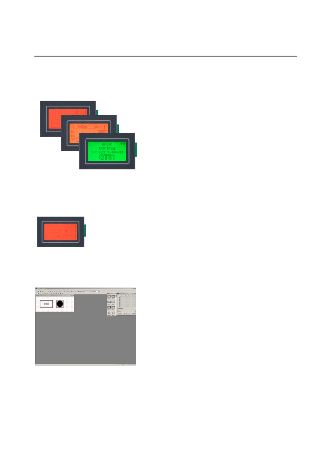
An Overview of GT Series Functions
3 colors can be displayed, to reflect the status (GT01 and GT11)
Various messages and graphics can be displayed on the liquid crystal display screen, as well as lamps,
internal PLC data and graphs. In addition, backlighting is available in three colors, green, orange, and
red, so that information can be color-coded. This makes it easy to grasp information at a glance.
Red
Orange
Green
High-resolution touch panel provided (GT01 and GT11)
A compact touch panel is provided with on-screen switches and a keyboard, letting you operate the unit
simply by touching the screen. As this is an analog touch panel, numerous switches can be used and
allows maximum flexibility in the switch layout and size.
Screens can be created easily, using special tools (GT01, GT11 and GT30)
Screen contents can be easily created using the dedicated Terminal GTWIN tool (runs on Windows
95/98/2000/NT/XP). Screens are put together simply by selecting parts from a library and positioning
them in place.
Screen data of the other models can be used with the model conversion function.
Screen data can be converted from the small-sized screen to the large-sized one. For the details, refer to
Terminal GTWIN Operational Guide Book.
xiii
Page 21
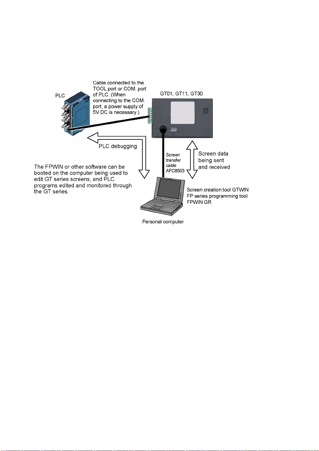
Through function is convenient for debugging (GT01, GT11 and GT30)
If connections are made as shown in the diagram, a convenient “through” function makes it possible to
transfer data from the GT and carry out PLC debugging at the same time that communication is going on
between the GT and the FP series PLC. This significantly boosts efficiency in the workplace.
xiv
Page 22

Page 23

Chapter 1
Specifications
Page 24
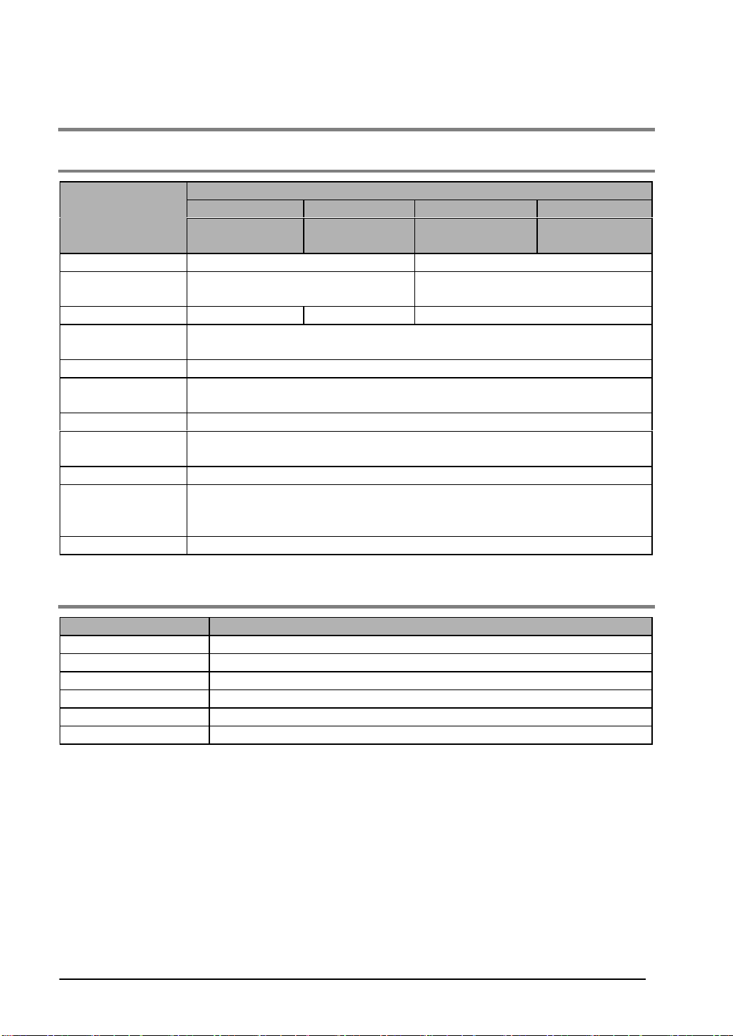
1.1 GT01 Specifications
1.1.1 General Specifications
GT01 specifications
Item
Rated voltage 5 V DC 24 V DC
Operating voltage
range
Power consumption 1W or less 1.1 W or less 2 W or less
Ambient
temperature
Ambient humidity 20 to 85% RH (at 25 °C, non-condensing)
Storage
temperature
Storage humidity 10 to 85% RH (at 25 °C, non-condensing)
Vibration resistance
Shock resistance 98 m/s2 or more, 4 times on 3 axes
Protective
construction
Weight Approx. 160 g
5V, RS232C type 5V, RS422 type 24V, RS232C type 24V, RS422 type
AIGT0030B1/
AIGT0030H1
4.5 to 5.5 V DC 21.6 to 26.4 V DC
0 to +50 °C
-20 to +60 °C
10 to 55 Hz (1-minute cycle)
Amplitude: 0.75 mm, 10 min on 3 axes
IP65 (in initial status)
Dustproof and drip-proof from front panel only (packing used on panel contact
surface) * When reattaching, replace waterproof packing.
AIGT0032B1/
AIGT0032H1
AIGT0030B/
AIGT0030H
AIGT0032B/
AIGT0032H
1.1.2 Display
Item GT01 specifications
Display STN monochrome LCD
Resolution 128 (W) x 64 (H) dots
Display color 2 colors (balck/white)
Displayable area 70.38 (W) x 35.18 (H) mm
LCD life Average 50,000 hours (at 25 °C room temperature)
Backlight 3-color LED backlight (green, red, orange) * No need to replace.
1-2
Page 25
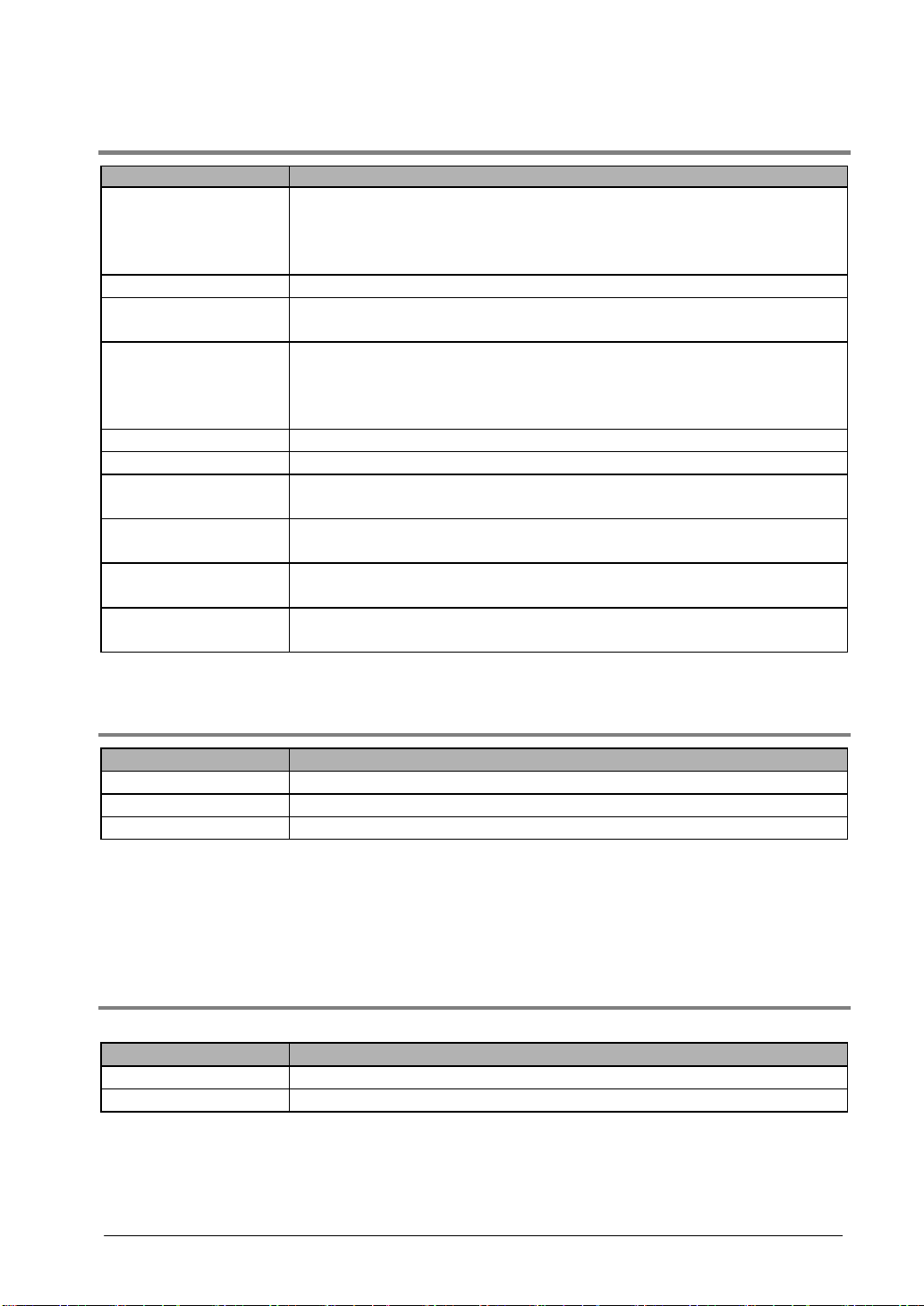
1.1.3 Functions
Item GT01 specifications
Fixed fonts: 1/4 width (8 x 8), half width (16 x 8), full width (16 x 16)
Displayable fonts
Character types Alphanumeric characters
Graphics
Number of screens
Part functions Messages, lamps, switches, data, bar graphs, keyboard, line chart
Contrast adjustment Contrast can be adjusted using touch panel operation.
Automatic
communication settings
Debugging functions
Screen creation
Password function
Note) Clock functions are not available.
Half width and full width characters can be displayed at same width,
doubled width, or quadrupled width
True Type fonts and Windows fonts
Straight lines, continuous straight lines, squares, circles, ovals, arcs, elliptic
arcs, fan shapes, elliptic fan shapes, beveled squares, bitmaps
Approx. 160 screens
Screen numbers that can be set: Base screens No. 00 to FF
* Number of screens that can be registered varies depending on registered
contents.
Setting for communication between dedicated software and PLC set
automatically by connecting cable.
Through function (PLC can be debugged from personal computer by
connecting computer to TOOL port and PLC to COM. port.)
Dedicated software is used.
Applicable OS: Windows 95/98/Me/2000/NT/XP
Screen data transfer or capture cannot be executed without a password
(screen data protection function).
1.1.4 Touch Key
Item GT01 specifications
Touch key Analog touch key
Touch key operation 0.5 N or less
Touch key life Min. 10
Note1) The GT01 touch-switches operate using analog resistance membrane. Do not press two or more
points on the screen at the same time. Doing so might operate a switch located between those
points if one exists.
Note2) This touch-panel is designed to be operated by touching. Please realize that the positional
accuracy of the switches is based on the size of a finger.
6
1.1.5 Memory
Screen data and GTWIN Configuration Settings data
Item GT01 specifications
Memory type F-ROM
Memory chapacity 384 kbytes
1-3
Page 26
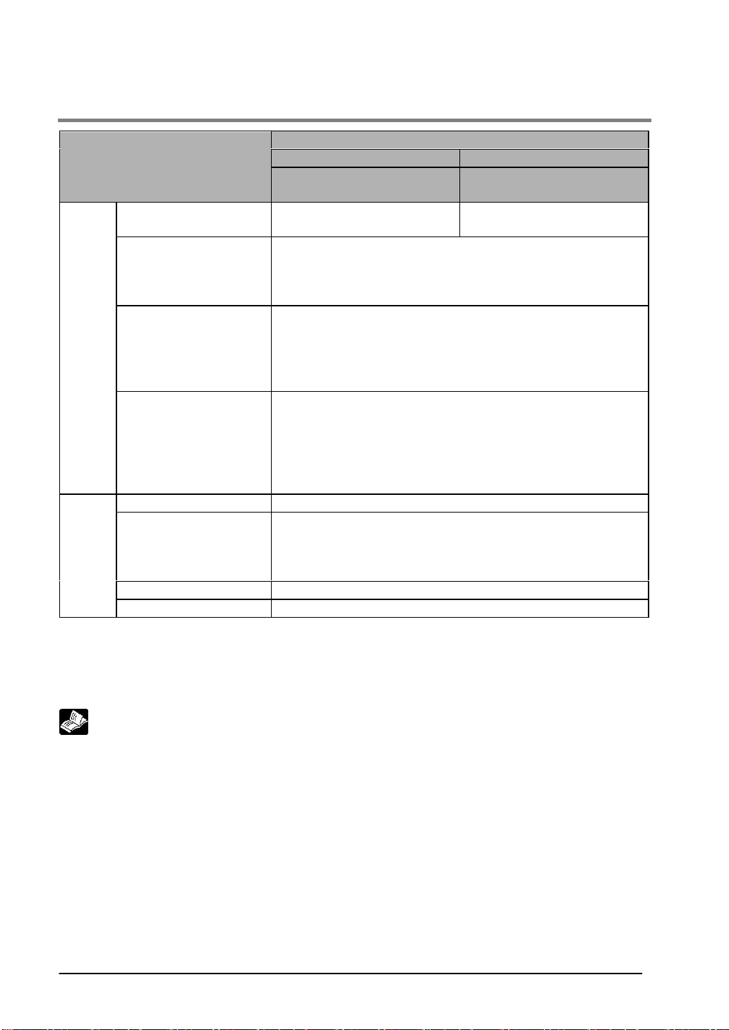
1.1.6 Serial Interface
GT01 specifications
Item
Communications ratings
Conditions for
communications with
external devices
COM.
port
TOOL
port
Note1) RS232C data transmission speed is 19,200 bit/s and the maximum cable length is 15 m.
Note2) Maximum cable length for RS422 data transmission is 30 m for the 5 V type and 500 m for the
Note3) When running a 5 V type directly with the PLC power supply, please comply with the PLC
Protocol
Connector
Communications ratings Conforms to RS232C (Non insulation type)
Conditions for
communications with
external devices
Protocol Dedicated protocol
Connector Mini-DIN (5-pin)
24 V type.
restrictions. For this reason, you may not be able to use at the distances given above.
Conforms to RS232C
(Non insulation type)
Baud rate: 9600, 19200, 38400, 57600, 115200 bps
Data bits: 7 or 8 bits
Parity: Non, Odd, Even
Stop bit: 1 bit
Supports MEW FP Series/General-purpose Serial/Mitsubishi FX
Series/Mitsubishi A (calculator link) Series/Omron SYSMAC-C
Series/Modbus (RTU)/Siemens S7-200 Series/Toshiba Machine
PROVISOR TCmini Series/Yokogawa FA-M3 Series/AllenBradly SLC500 Series/LG MASTER-K (Cnet) Series
Connector terminal base (8-pin)
* Regarding power supply voltage, please pay due consideration
to the cable length so that the applied voltage is within the
operation voltage range. Also, when supplying power from a
power supply separate from the PLC, please make sure the
power cable is no longer than 10 m.
Baud rate: 9600, 19200, 115200 bps
Data bits: 8 bits
Parity: Non, Odd, Even
Stop bit: 1 bit
RS232C type RS422 type
AIGT0030B1/AIGT0030H1
AIGT0030B/AIGT0030H
AIGT0032B1/AIGT0032H1
AIGT0032B/AIGT0032H
Conforms to RS422
(Non insulation type)
Reference:
For information on connecting and wiring the cables, refer to <Chapter 4 Connecting and
Communicating with the PLC> and <GTWIN HELP>..
1-4
Page 27
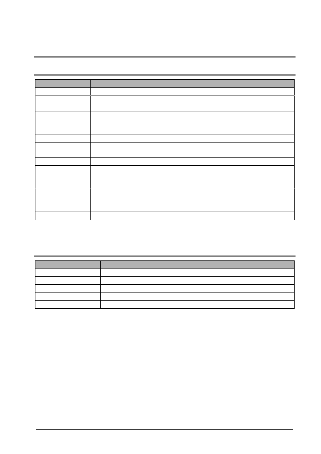
1.2 GT11 Specifications
1.2.1 General Specifications
Item GT11 specifications
Rated voltage 24 V DC
Operating voltage
range
Power consumption 2.4 W or less (100 mA or less)
Ambient
temperature
Ambient humidity 20 to 85% RH (at 25 °C, non-condensing)
Storage
temperature
Storage humidity 10 to 85% RH (at 25 °C, non-condensing)
Vibration resistance
Shock resistance 98 m/s2 or more, 4 times on 3 axes
Protective
construction
Weight Approx. 230 g
Note) If using cables other than the cables manufactured by us, use shielded cables, and attach ferrite
cores for the noiseproof measures if necessary.
21.6 to 26.4 V DC
0 to +50 °C
-20 to +60 °C
10 to 55 Hz (1-minute cycle)
Amplitude: 0.75 mm, 10 min on 3 axes
IP65 (in initial status)
Dustproof and drip-proof from front panel only (packing used on panel contact
surface) * When reattaching, replace waterproof packing.
1.2.2 Display
Item GT11 specifications
Display STN monochrome LCD
Resolution 240 (W) x 96 (H) dots
Displayable area 96.0 (W) x 35.4 (H) mm
Backlight 3-color LED backlight (green, red, orange)
Contrast adjustment Contrast can be adjusted on the menu screen.
1-5
Page 28
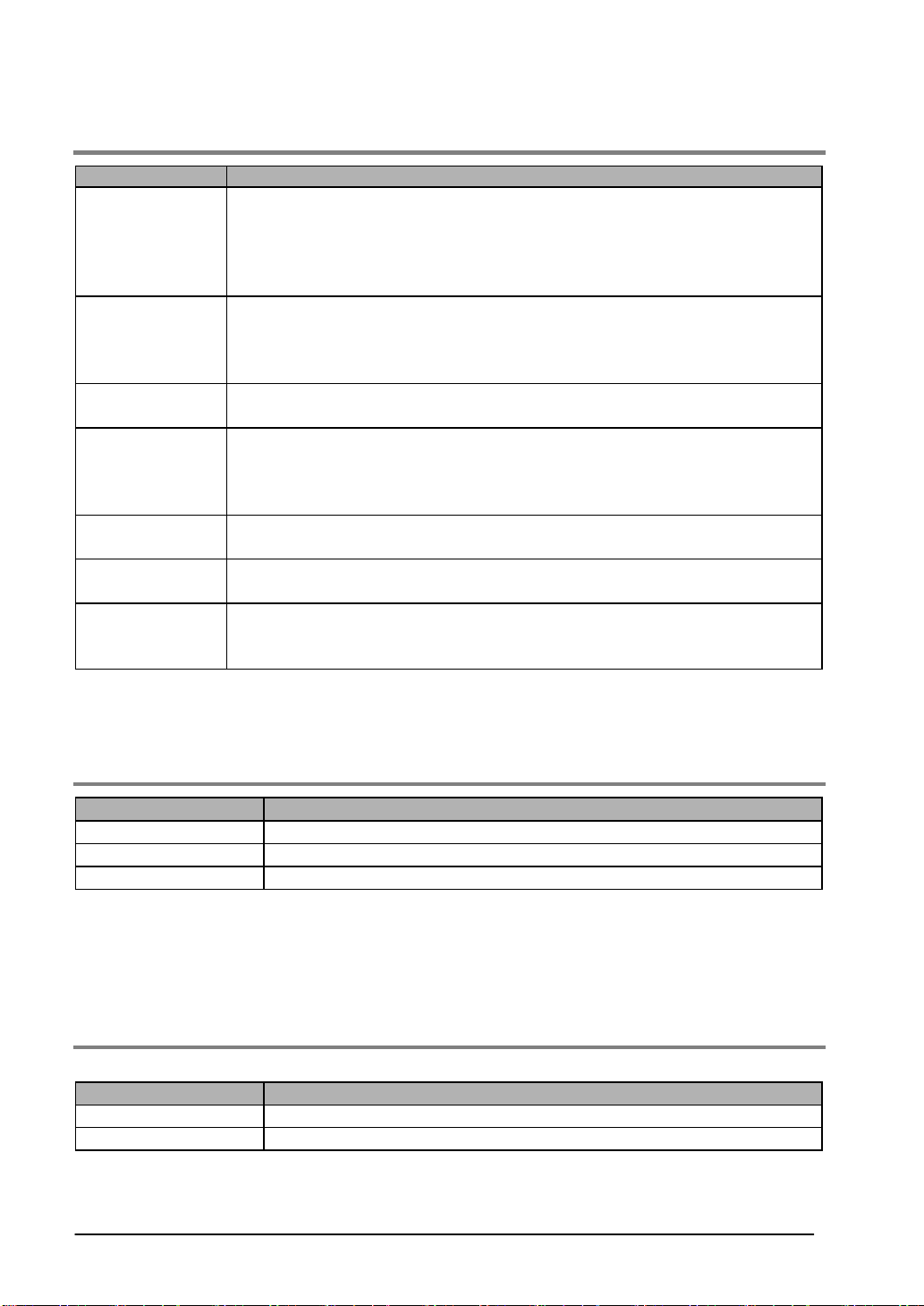
1.2.3 Functions
Item GT01 specifications
Fixed fonts: 1/4 width (8 x 8), half width (16 x 8), full width (16 x 16)
Half width and full width characters can be displayed at same width, doubled
Displayable fonts
Character types
Graphics
Number of
screens
Part functions
Other functions
Through function
Note1) The clock part can be indicated by referring to external clock data.
Note2) When using the built-in clock or bakcing up the alaram history , purchase and install a
commercial battery.
width, or quadrupled width
True Type fonts: 10, 12, 14, 16, 24, 26, 28, 32, 36, 48, 64 dots and Windows
True Type fonts
Alphanumeric characters
(English, Japanese, Korean, Germany, French, Spanish, Simplified Chinese and
Traditional Chinese characters can be displayed using the screen creation tool
GTWIN.)
Straight lines, continuous straight lines, squares, circles, ovals, arcs, elliptic arcs,
fan shapes, elliptic fan shapes, beveled squares, bitmaps
Approx. 250 screens (monochrome LCD type)
Screen numbers that can be set: Base screens No. 00 to 3FF
* Number of screens that can be registered varies depending on registered
contents.
Messages, lamps, switches, data, bar graphs, keyboard, line graphs
Note2)
Recipe functionm Flow display function, Write device function,
Note2)
Alarm history function
, Multi language exchange function
PLC can be communicated with personal computer by connecting computer to
TOOL port and PLC to COM. port. (This function is not available for PLCs
manufactured by other companies.)
Clock Note1)
1.2.4 Touch Key
Item GT11 specifications
Touch key Analog touch key (resistive film type)
Touch key operation 0.5 N or less
Touch key life Min. 10
6
Note1) The GT01 touch-switches operate using analog resistance membrane. Do not press two or more
points on the screen at the same time. Doing so might operate a switch located between those
points if one exists.
Note2) This touch-panel is designed to be operated by touching. Please realize that the positional
accuracy of the switches is based on the size of a finger.
1.2.5 Memory
Screen data and GTWIN Configuration Settings data
Item GT11 specifications
Memory type F-ROM
Memory chapacity 1.375 Mbytes
1-6
Page 29
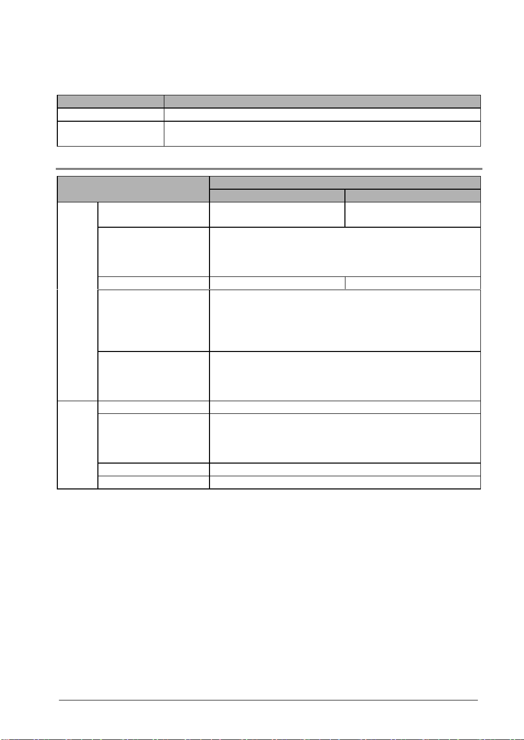
Clock data, PLC device storage data (24 words max.) and alarm history
Item GT11 specifications
Memory SRAM
Memory backup
Lithium battery (replaceable type)
CR2032 (commercially available)
1.2.6 Serial Interface
COM.
port
TOOL
port
Item
Communications ratings
Conditions for
communications with
external devices
Transmission distance Max. 15 m (RS232C) Max. 500 m (RS422)
Protocol
Connector
Communications ratings Conforms to RS232C (Non insulation type)
Conditions for
communications with
external devices
Protocol Dedicated protocol for GT
Connector Mini-DIN (5-pin)
AIGT2030B/AIGT2030H AIGT2032B/AIGT2032H
Conforms to RS232C
(Non insulation type)
Baud rate: 9600, 19200, 38400, 57600, 115200 bps
Data bits: 7 or 8 bits
Parity: Non, Odd, Even
Stop bit: 1 bit
Supports MEW FP Series/General-purpose Serial/Mitsubishi FX
Series/Mitsubishi A (calculator link) Series/Omron SYSMAC-C
Series/Modbus (RTU)/Siemens S7-200 Series/Toshiba Machine
PROVISOR TCmini Series/Yokogawa FA-M3 Series/AllenBradly SLC500 Series/LG MASTER-K (Cnet) Series
Connector terminal base (8-pin)
* Regarding power supply voltage, please pay due consideration
to the cable length so that the applied voltage is within the
operation voltage range.
Baud rate: 9600, 19200, 115200 bps
Data bits: 8 bits
Parity: Non, Odd, Even
Stop bit: 1 bit
GT11 specifications
Conforms to RS422
(Non insulation type)
1-7
Page 30
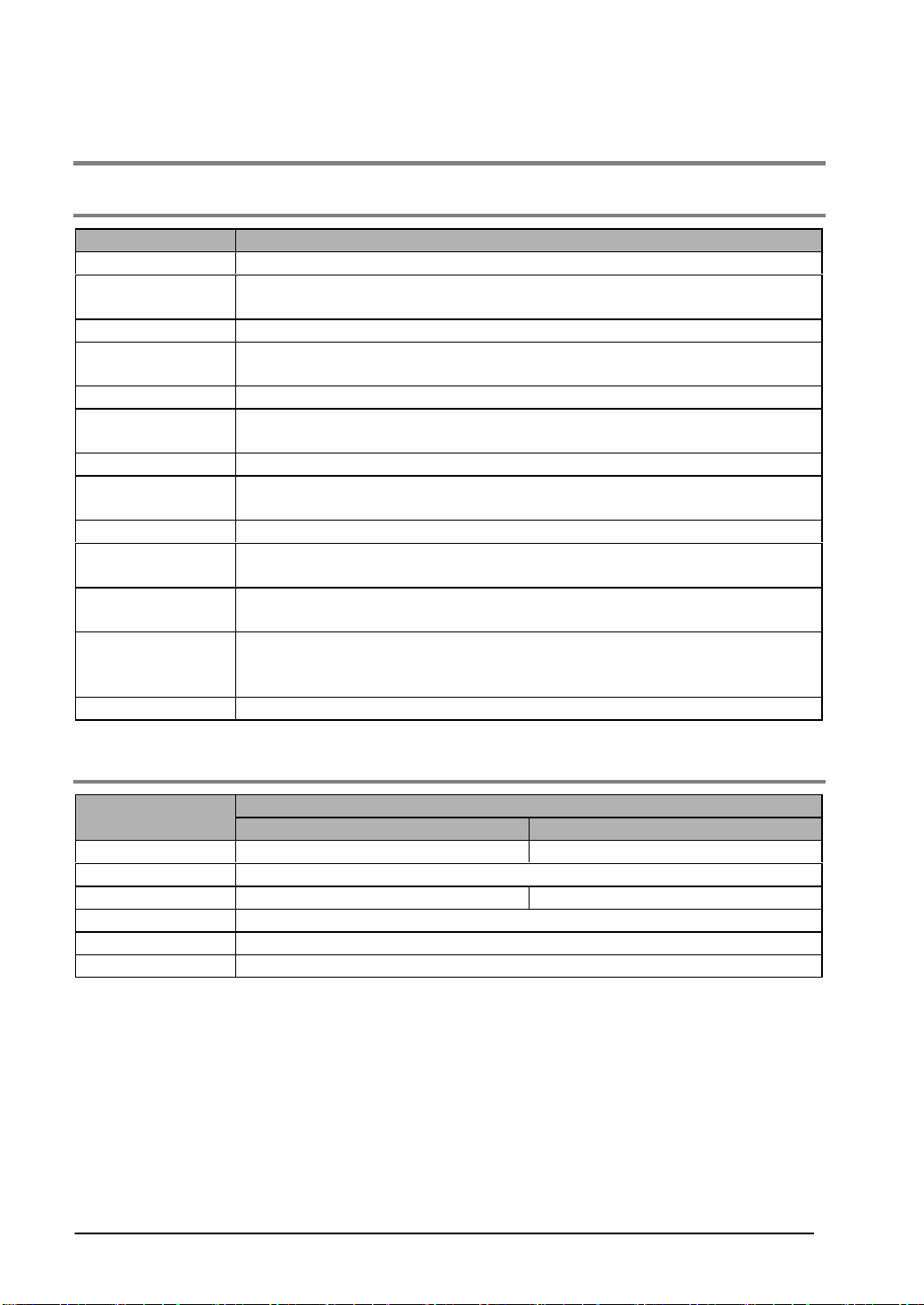
1.3 GT30 Specifications
1.3.1 General Specifications
Item GT30 specifications
Rated voltage 24 V DC
Operating voltage
range
Power consumption 10 W or less
Ambient
temperature
Ambient humidity 20 to 85% RH (at 25 °C, non-condensing)
Storage
temperature
Storage humidity 10 to 85% RH (at 25 °C, non-condensing)
Vibration resistance
Shock resistance 98 m/s2 or more, 4 times on 3 axes
Noise immunity
Static noise
resistance
Protective
construction
Weight Approx. 440 g
21.6 to 26.4 V DC
0 to +50 °C (25 V DC max. if installed horizonally)
-20 to +60 °C
10 to 55 Hz (1-minute cycle)
Amplitude: 0.75 mm, 10 min on 3 axes
1,000 V[p-p] min., pulse width 50 ns, 1µs between power supply terminals
(based on noise simulator)
5,000 V min. (panel display)
IP65 (in initial status)
Dustproof and drip-proof from front panel only (packing used on panel contact
surface) * When reattaching, replace waterproof packing.
1.3.2 Display
Item
Display STN monochrome LCD STN color LCD
Resolution 320 (W) x 240 (H) dots
Display color 2 colors (balck/white) 16 colors
Displayable area 118.18 (W) x 89.38 (H) mm
LCD life Average 50,000 hours (at 25 °C room temperature)
Backlight CFL *Average backlight service life: 50,000 hours (25 °C)
1-8
AIGT3100B AIGT3300B
GT30 specifications
Page 31
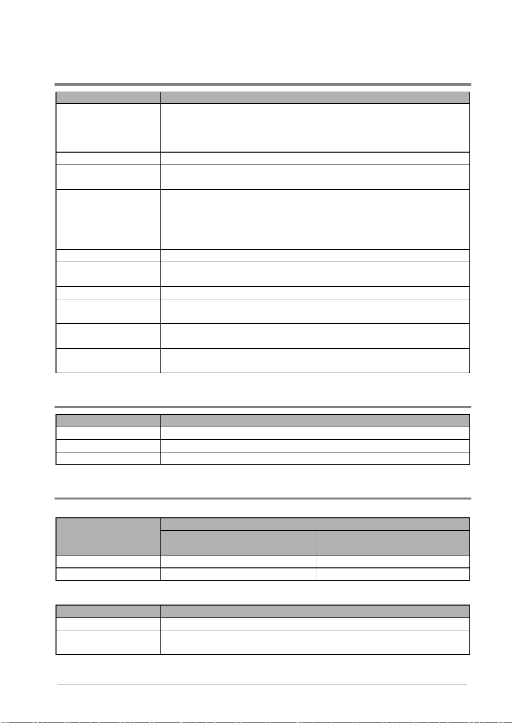
1.3.3 Functions
Item GT30 specifications
Fixed fonts: 1/4 width (8 x 8), half width (16 x 8), full width (16 x 16)
Displayable fonts
Character types Alphanumeric characters
Graphics
Number of screens
Part functions Messages, lamps, switches, data, bar graphs, keyboard
Clock function
Contrast adjustment Contrast can be adjusted using touch panel operation. (10 levels)
Automatic
communication settings
Debugging functions
Screen creation
Half width and full width characters can be displayed at same width,
doubled width, or quadrupled width
True Type fonts
Straight lines, continuous straight lines, squares, circles, ovals, arcs, elliptic
arcs, fan shapes, elliptic fan shapes, beveled squares, bitmaps
Approx. 220 screens (monochrome LCD type)
Approx. 160 screens (color LCD type)
Screen numbers that can be set: Base screens No. 00 to 3FF
* Number of screens that can be registered varies depending on registered
contents.
Clock built into main unit (can also be displayed with reference to PLC
clock)
Setting for communication between dedicated software and PLC set
automatically by connecting cable.
Through function (PLC can be debugged from personal computer by
connecting computer to TOOL port and PLC to COM. port.)
Dedicated software is used.
Applicable OS: Windows 95/98/Me/2000/NT
1.3.4 Touch Key
Item GT30 specifications
Touch key resolution 16 (W) x 12 (H)
Touch key operation 0.98 N or less
Touch key life Min. 10
6
1.3.5 Memory
Screen data and GTWIN Configuration Settings data
GT30 specifications
Item
Memory type F-ROM F-ROM
Memory chapacity 1.5 Mbytes 3.25 Mbytes
Clock data, PLC device storage data (24 words max.) and alarm history
Item GT30 specifications
Memory SRAM
Memory backup
Lithium battery (replaceable type)
CR2032 (commercially available)
AIGT3100B
(monochrome LCD type)
AIGT3300B
(color LCD type)
1-9
Page 32
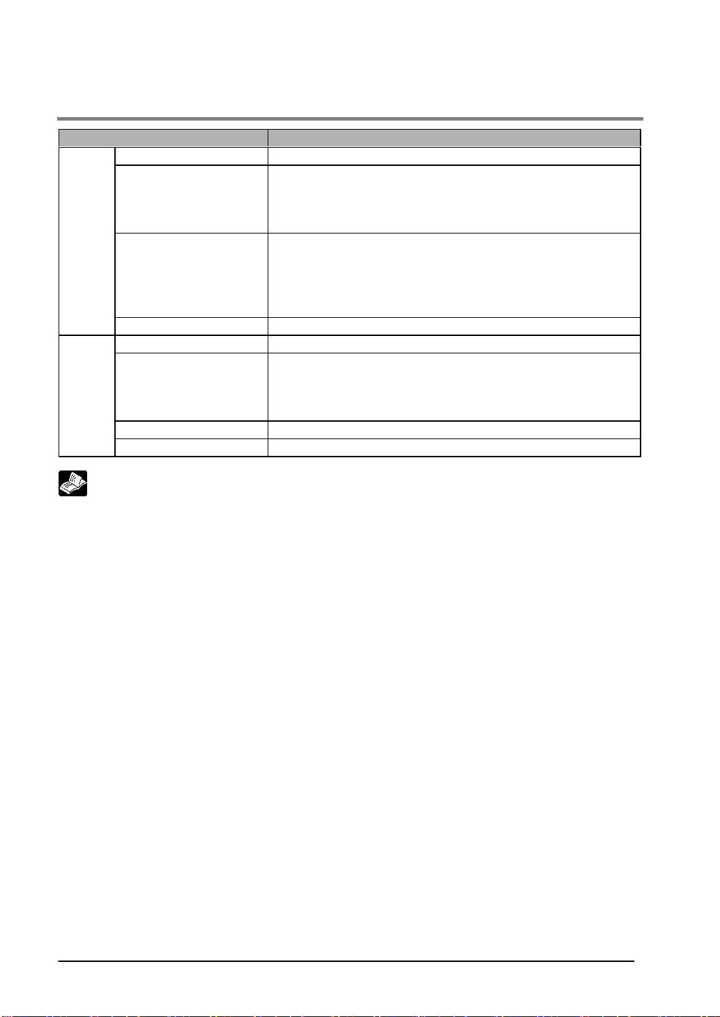
1.3.6 Serial Interface
Item GT30 specifications
Communications ratings Conforms to RS232C (Non insulation type)
Conditions for
communications with
external devices
COM.
port
Protocol
Connector Connector terminal base (5-pin)
Communications ratings Conforms to RS232C (Non insulation type)
Conditions for
TOOL
port
For information on connecting and wiring the cables, refer to <Chapter 4 Connecting and
Communicating with the PLC> and <GTWIN HELP>.
communications with
external devices
Protocol Dedicated protocol
Connector Mini-DIN (5-pin)
Reference:
Baud rate: 9600, 19200, 38400, 57600, 115200 bps
Data bits: 7 or 8 bits
Parity: Non, Odd, Even
Stop bit: 1 bit
Supports MEW FP Series/General-purpose Serial/Mitsubishi FX
Series/Mitsubishi A (calculator link) Series/Omron SYSMAC-C
Series/Modbus (RTU)/Siemens S7-200 Series/Toshiba Machine
PROVISOR TCmini Series/Yokogawa FA-M3 Series/AllenBradly SLC500 Series/LG MASTER-K (Cnet) Series
Baud rate: 9600, 19200, 115200 bps
Data bits: 8 bits
Parity: Non, Odd, Even
Stop bit: 1 bit
1-10
Page 33
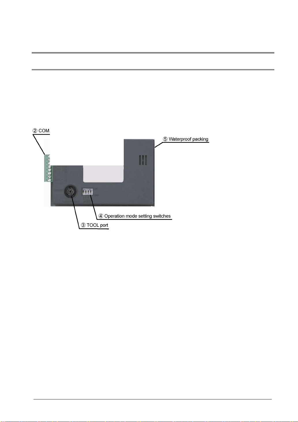
1.4 Names and Functions of Parts
1.4.1 GT01 and GT11
GT01 (front)
GT01 (rear)
1-11
Page 34
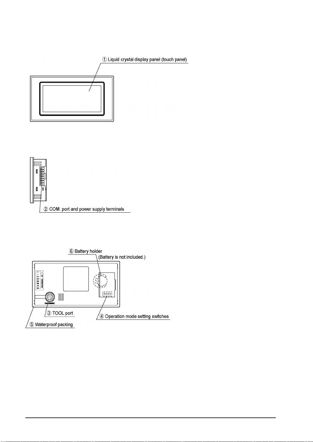
GT11 (front)
GT11 (side)
GT11 (rear)
1-12
Page 35
Names and functions of parts (for GT01 and GT11)
Liquid crystal display panel/touch panel
Various screens are displayed here. A touch panel is provided on the liquid crystal display panel, and
switches can be operated and data entered simply by touching the panel.
Optional protective sheets are also available to protect the touch panel and keep it cleean.
(A sheet is affixed to the touch panel to protect it from scratches when shipping. Please remove it before
using the GT.)
COM. port (PLC/external device connection port) and power supply terminal
This is a communication port (RS232C or RS422) for connecting to a PLC, host PC, or microcomputer
board, and a 5 V DC operation power supply terminal. (The GT is shipped with one communications
connector.)
TOOL port (GTWIN connection port)
This port is used to connect a personal computer in which the screen creation tool GTWIN has been
installed, using a dedicated cable (AFC8503).
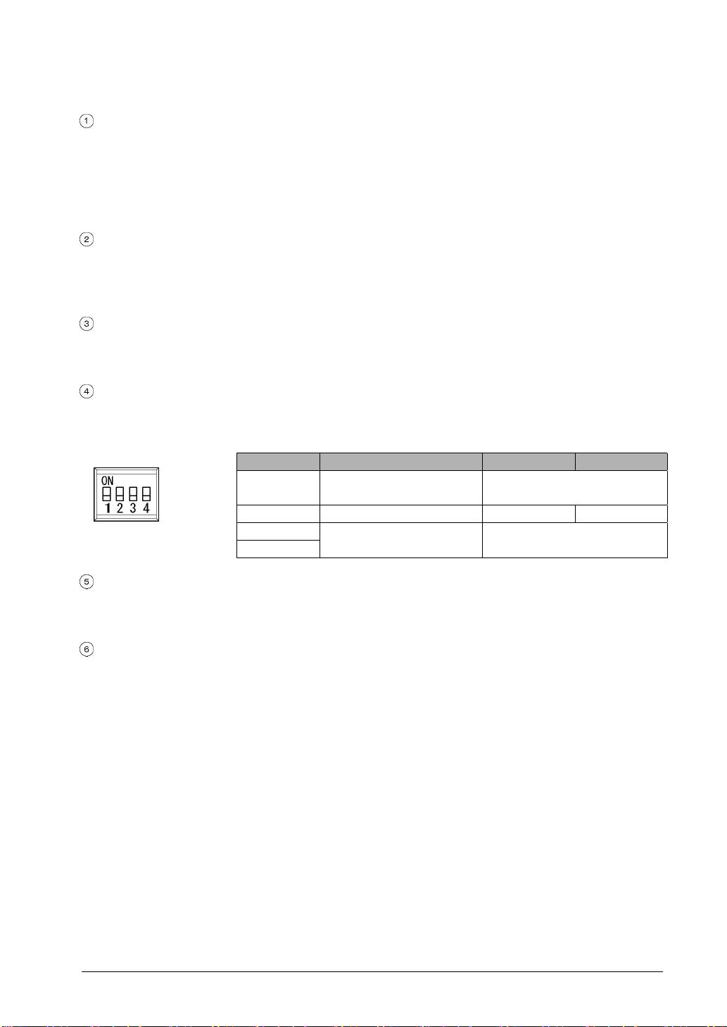
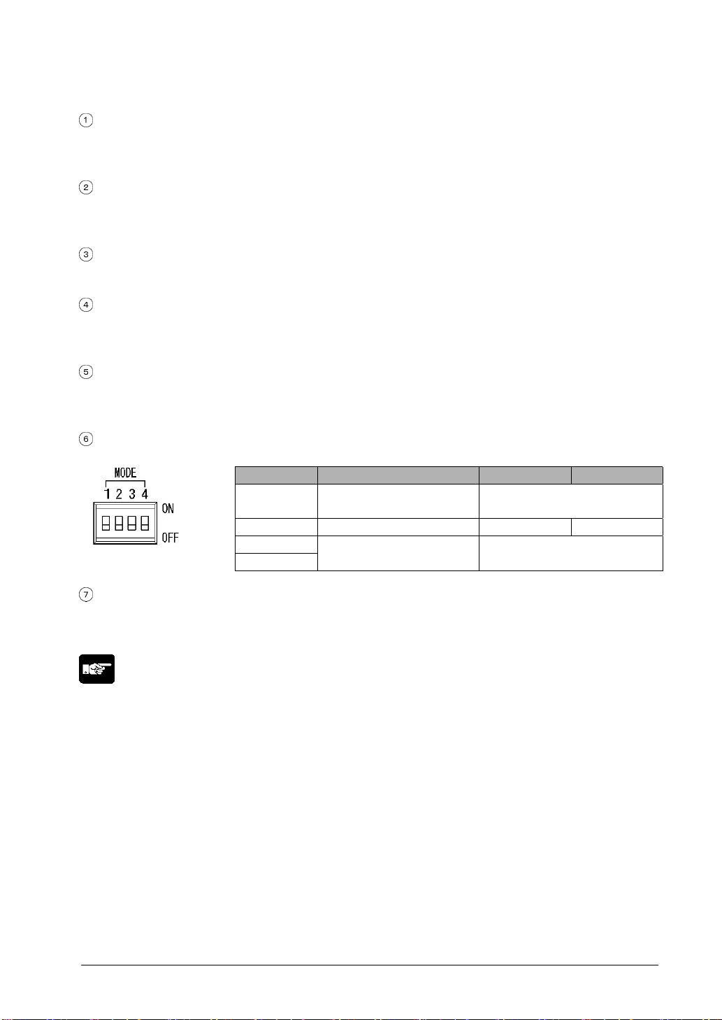
Operation mode setting switches
With the GT01, screen data and configuration settings data are stored in an internal F-ROM, so no
battery backup is needed. The operation mode setting swtich has a switch that prohibits access to the
System Menu.
Switch No. Function OFF ON
Should always be in the OFF
position when unit is used.
Should always be in the OFF
position when unit is used.
(settings when shipped)
1 Usage inhibited
2 Inhibits system menu shift Shift possible Shift inhibited
3
4
Usage inhibited
Waterproof packing
This assures that the front panel is waterproof. One piece is provided as an accessory when the unit is
shipped.
Battery holder (for GT11 only)
Install a battery into this holder when using the clock, PLC device hold data and alarm history. The
battery is not included when the unit is shipped. Please purchase the commercial CR2032.
1-13
Page 36
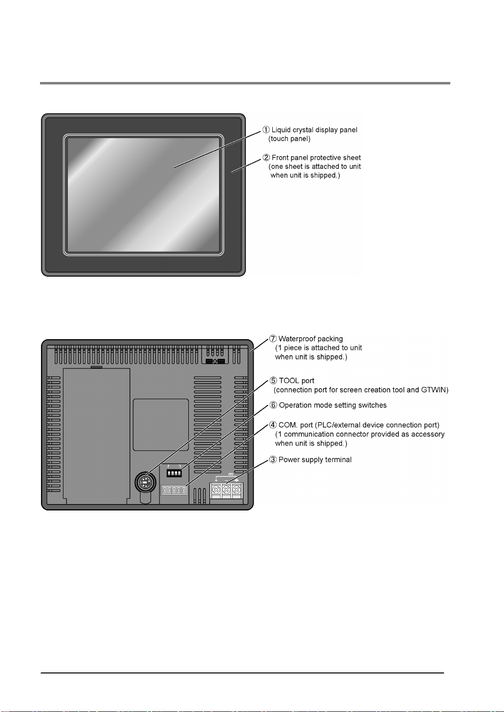
1.4.2 GT30
GT30 (front)
GT30 (rear)
1-14
Page 37
Names and functions of parts (for GT30)
Liquid crystal display panel/touch panel
Various screens are displayed here. A touch panel is provided on the liquid crystal display panel, and
switches can be operated and data entered simply by touching the panel.
Front panel protective sheet
This protects the touch panel and keeps it clean. One sheet is attached to the panel when the unit is
shipped.
Power supply terminal
The operation power supply is connected here.
COM. port (PLC/external device connection port)
This is a RS232C port for connecting to a PLC, host PC, or microcomputer board. (The GT is shipped
with one communications connector.)
TOOL port (GTWIN connection port)
This port is used to connect a personal computer in which the screen creation tool GTWIN has been
installed, using a dedicated cable (AFC8503).
Operation mode setting switches
The operation mode setting switches control the ability to shift to the system menu.
Switch No. Function OFF ON
Should always be in the OFF
position when unit is used.
Should always be in the OFF
position when unit is used.
(settings when shipped)
1 Usage inhibited
2 Inhibits system menu shift Shift possible Shift inhibited
3
4
Usage inhibited
Waterproof packing
This assures that the front panel is waterproof. One piece is provided as an accessory when the unit is
shipped.
Note:
• With the GT30, screen data and configuration settings are stored in the internal F-ROM. Clock data
and PLC device hold data are stored in the internal SRAM, and can be backed up by the lithium battery
(a replaceable battery). When replacing the lithium battery, be sure to insert the new battery within 20
seconds of removing the old one.
• Use commercial lithium battery CR2032.
1-15
Page 38
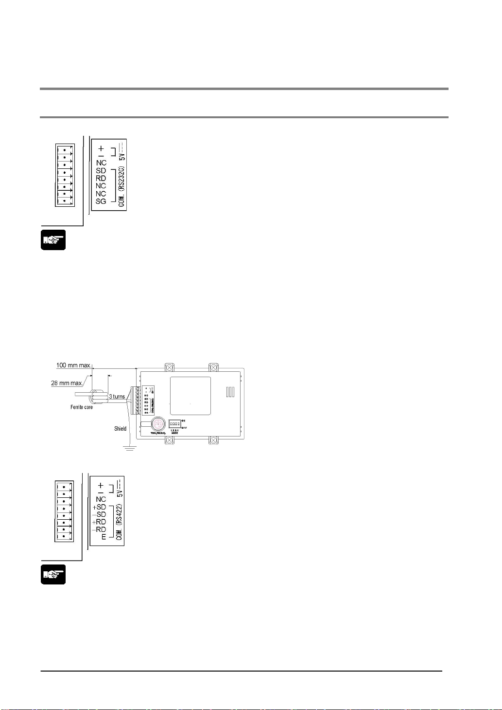
1.5 Internal Wiring Connections for Ports
1.5.1 COM. Port (GT01)
5 V/RS232C type (AIGT0030B1/AIGT0030H1)
Note:
• There is no RS and CS (control lines).
• Make sure that wiring and placement of the cable are performed so that there is no impression of
external noise on the cable and no induction. Also, shielded wiring should be used for cables.
• AIGT0030** conforms to EMC standards EN61000-6-4 and EN61000-6-2 of the European EMC
directive (EMC Directive 89/336/EEC). As conditions, the following is required.
1. Use shielded wire cables (equivalent of AIGT8142).
2. Make the cable do three turns of a ferrite core (equivalent fo Seiwa Electric’s E04RA190120080*).
3.Perform grounding of the cable shield.
* Packaged with AIGT8142.
5 V/RS422 type (AIGT0032B1/AIGT0032H1)
Note:
• There is no RS and CS (control lines).
• Make sure that wiring and placement of the cable are performed so that there is no impression of
external noise on the cable and no induction. If using a cable other than ours, use a shielded cable and
take countermeasures against noise such as by installing a ferrite core if necessary. (Recommended
ferrite core: Seiwa Electric’s E04RA190120080 or equivalent).
• “E” is used to set the terminating station.
1-16
Page 39
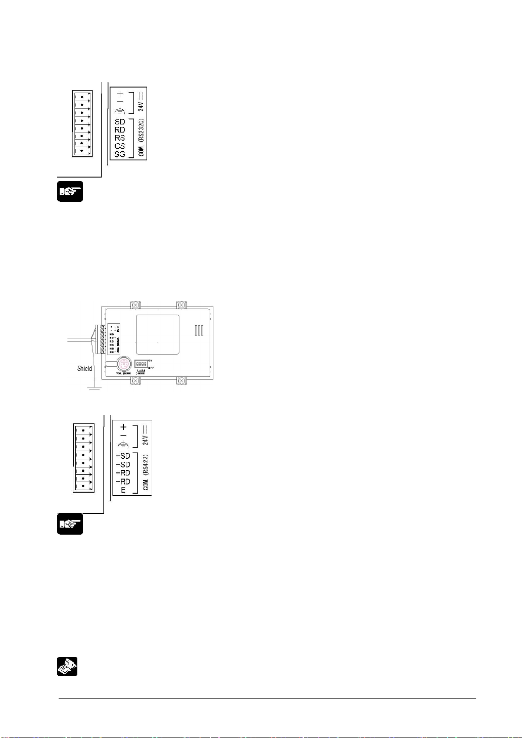
24 V/RS232C type (AIGT0030B/AIGT0030H)
Note:
• There is no RS and CS (control lines).
• Make sure that wiring and placement of the cable are performed so that there is no impression of
external noise on the cable and no induction. Also, shielded wiring should be used for cables.
• AIGT0030** conforms to EMC standards EN61000-6-4 and EN61000-6-2 of the European EMC
directive (EMC Directive 89/336/EEC). As conditions, the following is required.
1. Use shielded wire cables (equivalent of AIGT8162).
2.Perform grounding of the cable shield and GT01
24 V/RS422 type (AIGT0032B/AIGT0032H)
Note:
• There is no RS and CS (control lines).
• Make sure that wiring and placement of the cable are performed so that there is no impression of
external noise on the cable and no induction. Also, shielded wiring should be used for cables.
• AIGT0030** conforms to EMC standards EN61000-6-4 and EN61000-6-2 of the European EMC
directive (EMC Directive 89/336/EEC). As conditions, the following is required.
1. Use shielded wire cables (equivalent of AIGT8162).
• 2.Perform grounding of the cable shield and GT01
• “E” is used to set the terminating station.
Reference: <2.2.2 Grounding>
1-17
Page 40
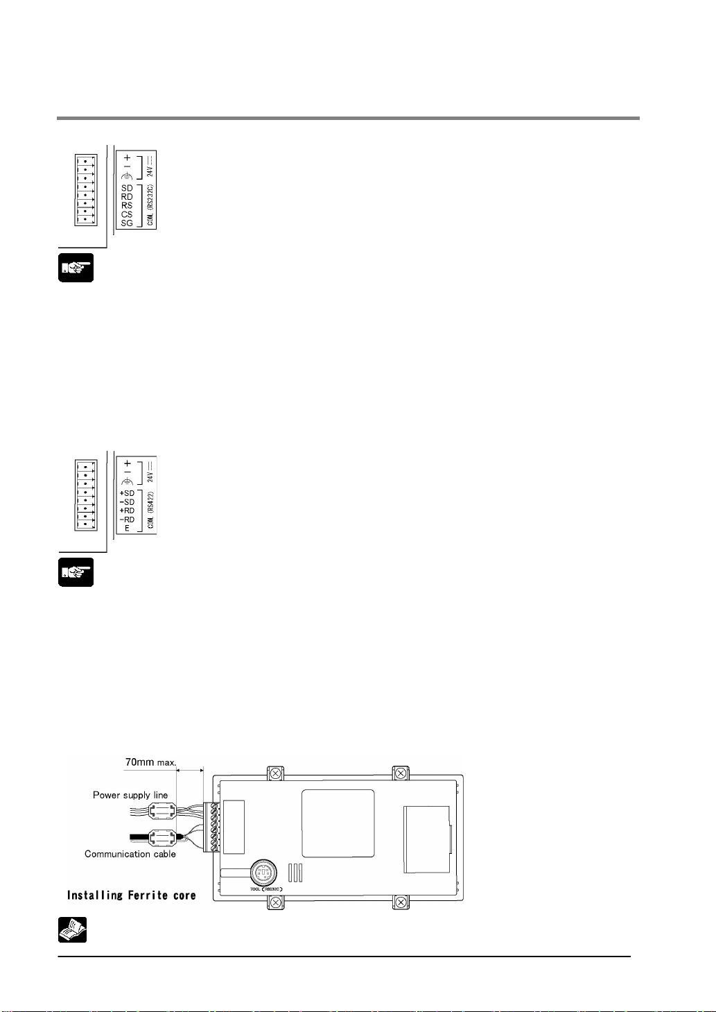
1.5.2 COM. Port (GT11)
24 V/RS232C type (AIGT2030B/AIGT2030H)
Note:
• Make sure that wiring and placement of the cable are performed so that there is no impression of
external noise on the cable and no induction. Also, shielded wiring should be used for cables.
• The power supply should be non-insulation type DC power supply.
• AIGT0030* HAOUSHUU conforms to EMC standards EN61000-6-4 and EN61000-6-2 of the European
EMC directive (EMC Directive 89/336/EEC). As conditions, the following is required.
1. Use shielded wire cables (equivalent of AIGT8162).
2. Install a ferrite core on the cables (Seiwa Electric’s E04SR170730A). (Refer to the figure below.)
3.Perform grounding of the cable shield.
24 V/RS422 type (AIGT0032B/AIGT0032H)
Note:
• There is no RS and CS (control lines).
• Make sure that wiring and placement of the cable are performed so that there is no impression of
external noise on the cable and no induction. Also, shielded wiring should be used for cables.
• “E” is used to set the terminating station.
• The power supply should be non-insulation type DC power supply.
AIGT2032 conforms to EMC standards EN61000-6-4 and EN61000-6-2 of the European EMC directive
(EMC Directive 89/336/EEC). As conditions, the following is required.
1. Use shielded wire cables.
2. Install a ferrite core on the cables (Seiwa Electric’s E04SR170730A). (Refer to the figure below.)
3.Perform grounding of the cable shield.
Reference: <2.2.2 Grounding>
1-18
Page 41
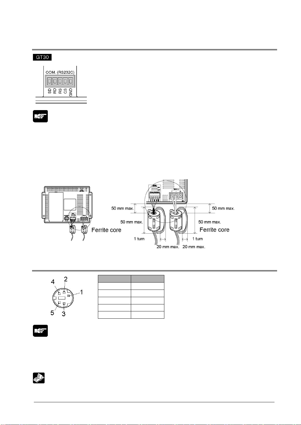
1.5.3 COM. Port (GT30)
Note:
• When connecting the unit to the FP series, there is no need to wire both the RS and CS.
• Make sure that wiring and placement of the cable are performed so that there is no impression of
external noise on the cable and no induction. Also, shielded wiring should be used for cables.
• GT30 conforms to EMC standards EN61000-6-4 and EN61000-6-2 of the European EMC directive
(EMC Directive 89/336/EEC). As a condition of compatible, a ferrite core should be installed when
wiring to the therminal base (Seiwa Electric’s E04RS211132 or equivalent). When installing make sure
that the connection and power cables are not stressed, as this could result in broken connections.
1.5.4 TOOL Port
Pin No. Contents
1SG
2SD
3RD
4N.C.
Note:
• The +5V of Pin 5 is reserved for the FP Programmer II. It should not be used for any other application.
If using it, there is a restriction on the ambient temperature. The pin 5 of GT01 is N.C.
When handling, make sure that the metal parts of the TOOL port are not stressed excessively.
Reference: For the details on Pin 5, refer to <Chapter 2 Installation and Wiring>
5(+5V)
1-19
Page 42
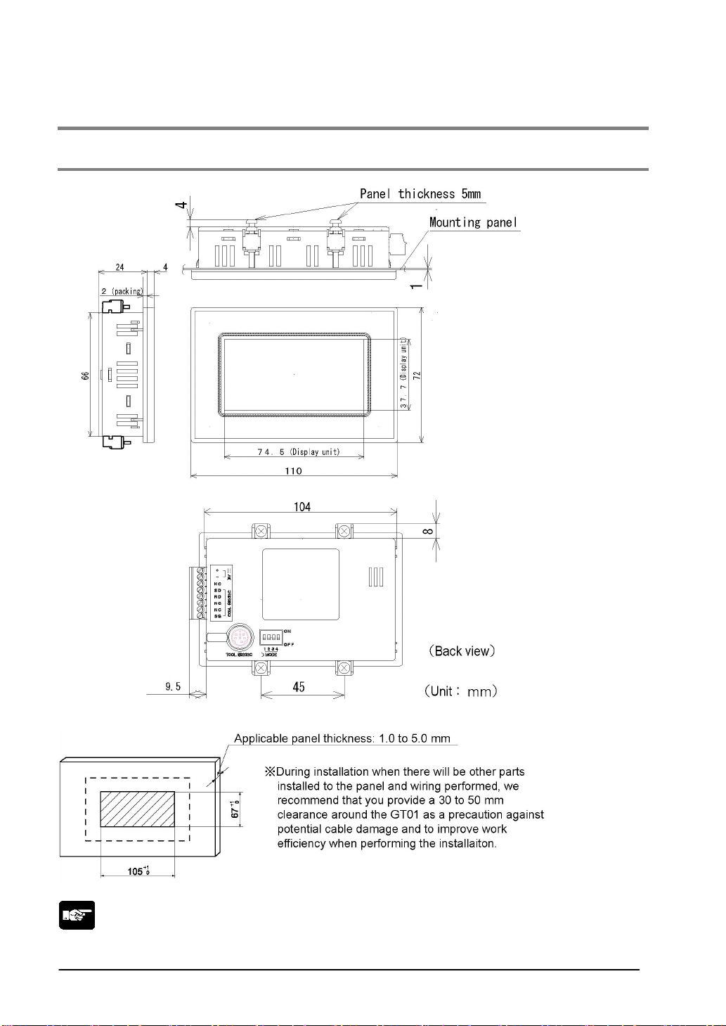
1.6 Dimensions
1.6.1 GT01
Panel cutout dimensions
Note:
Be absolutely sure not to seal the slits on the unit.
1-20
Page 43
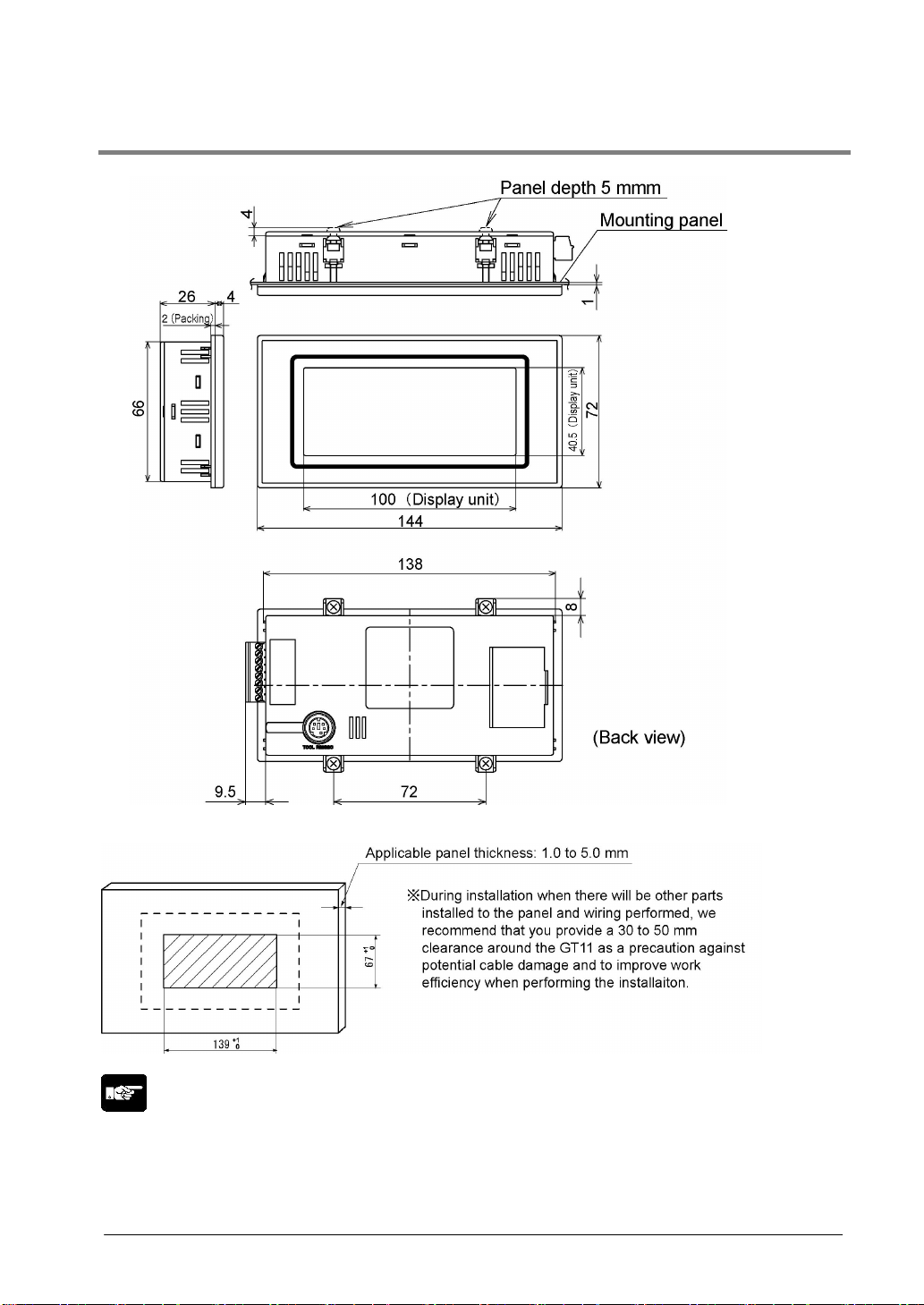
1.6.2 GT11
Panel cutout dimensions
Note:
Be absolutely sure not to seal the slits on the unit.
1-21
Page 44
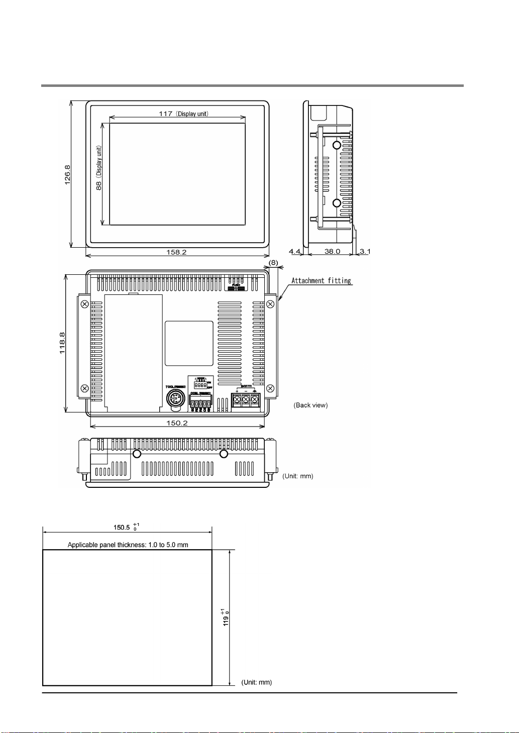
1.6.3 GT30
Panel cutout dimensions
1-22
Page 45

Chapter 2
Installation and Wiring
Page 46

2.1 Installation
2.1.1 Installation Environment
When installing and using the GT series, always make sure the following conditions are observed.
Usage conditions
When installing the product, make sure it is used within the range of the general specifications. Do not
use in the following environments:
• Areas whwere the unit may come in contact with water (the unit is warranted by IP65 for the installed
panel, but this applies to initial values and operation cannot be guaranteed in areas where the unit is
constantly subjected to water or to extreme temperature or humidity.)
• Areas where the ambient temperature exceeds the range 0 to 50 °C.
• Areas where the ambient humidity exceeds 20 to 85% RH (at 25 °C non-condensing).
• If the control panel and other parts are installed in an environment where the air tends to be poorly
ventilated, forced cooling should be used to keep the ambient temperature of the from going over 50 °C.
This prevents the temperature of the GT main unit from rising.
• Locations where condensation may form because of sudden fluctuations in temperature.
• Locations where flammable or corrosive gases are present.
• Locations where there are high concentrations of dust or iron filings.
• Locations where substances such as organic solvents (thinner , benzene, etc.) or strong alkali
substances (ammonia, caustic soda, etc.) might adhere to the product.
• Locations where the product is subject to extreme vibration and/or impact.
• Avoid installing the product near high-voltage lines, high-voltage devices, power lines, power devices,
amateur radio sets and other transmitters, and devices that generate strong current surges.
• Avoid locations where the display unit is subject to direct sunlig ht.
Safety precautions
The switch functions of the programmable display unit should not be used to design systems which may
pose a threat to human life or which may cause severe injury or damage. Designs should include safety
mechanisms for use in the event that switch functions do not function correctly.
Power supply wiring
• For the power supply, use twisted wire (strand wire).
• There is sufficient noise resistance to offset power line noise, but we recommend reducing noise by
measures such as installing an insulated transformer.
• Separate wiring systems should be used for the power supply unit and the operating unit.
Static Electricity/Noise
• Keep the GT main unit, PLC connecting cable, and other wiring as far away as possible from
machines which are likely to produce noise (welding equipment, power lines, inverters, motors, etc.)
• For use in environm ents where the frequent occurrence of stat ic electricity, radiation, or induced noise
can be expected, the use of shielded cable on all wiring and grounding of shield (1-point ground) is
recommended. When wiring the equipment, shielded wires should be electrically insulated to signal
lines and signal grounds.
• If excessive static electricity is applied to the panel surface, the LCD display unit may be damaged.
2-2
Page 47
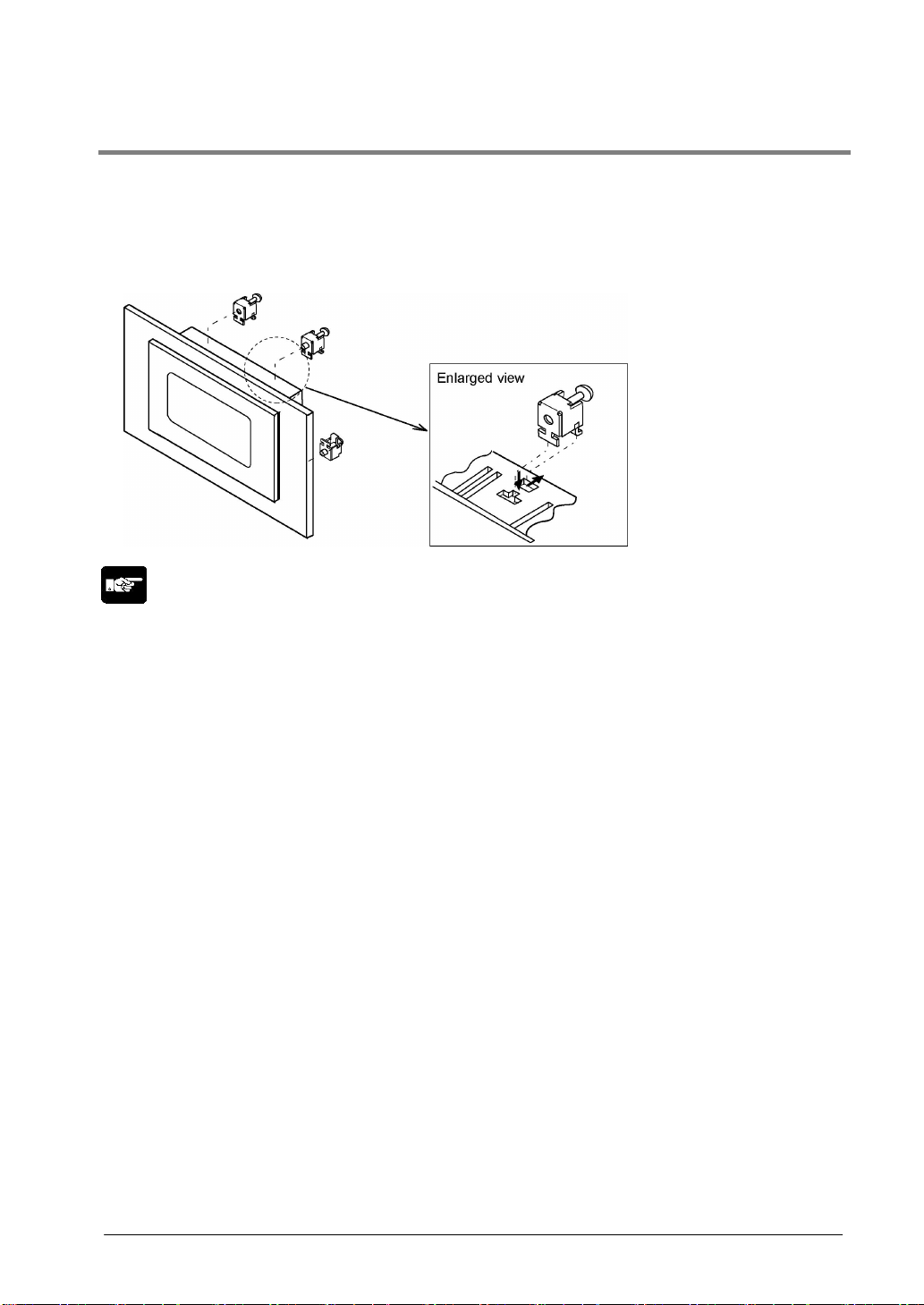
2.1.2 GT01 and GT11 Installation Method
Secure the GT to the installation panel using the four fittings and four screws provided with the unit.
1. Place the GT main unit in the installation panel.
2. Insert the fittings into the grooves provided in the GT main unit, and tighten the screws to
secure the GT main unit to the installation panel.
Note:
Screw tightening torque
The screw tightening torque should be 0.1 N m to 0.25 N m. Tightening screws too hard may be a cause
to deform the case and other parts, and may cause to deteriorate the waterproof property or damages in
the functions.
Applicable panel thickness
A panel with a thickness of 1.0 to 5.0 mm should be used.
Clearance when the GT is installed
When installing the GT, if other parts are being installed to the panel or cables are being wired to it, we
recommend providing a clearance of 30 to 50 mm around the GT. This prevents cables from being
damaged, and facilitates the installation work. Also, make sure that the slits in the main unit are never
obstructed.
When using the GT11 connecting our Programmer II or C-NET adapter to the TOOL port
Usable ambient temperature is 45 °C.
2-3
Page 48
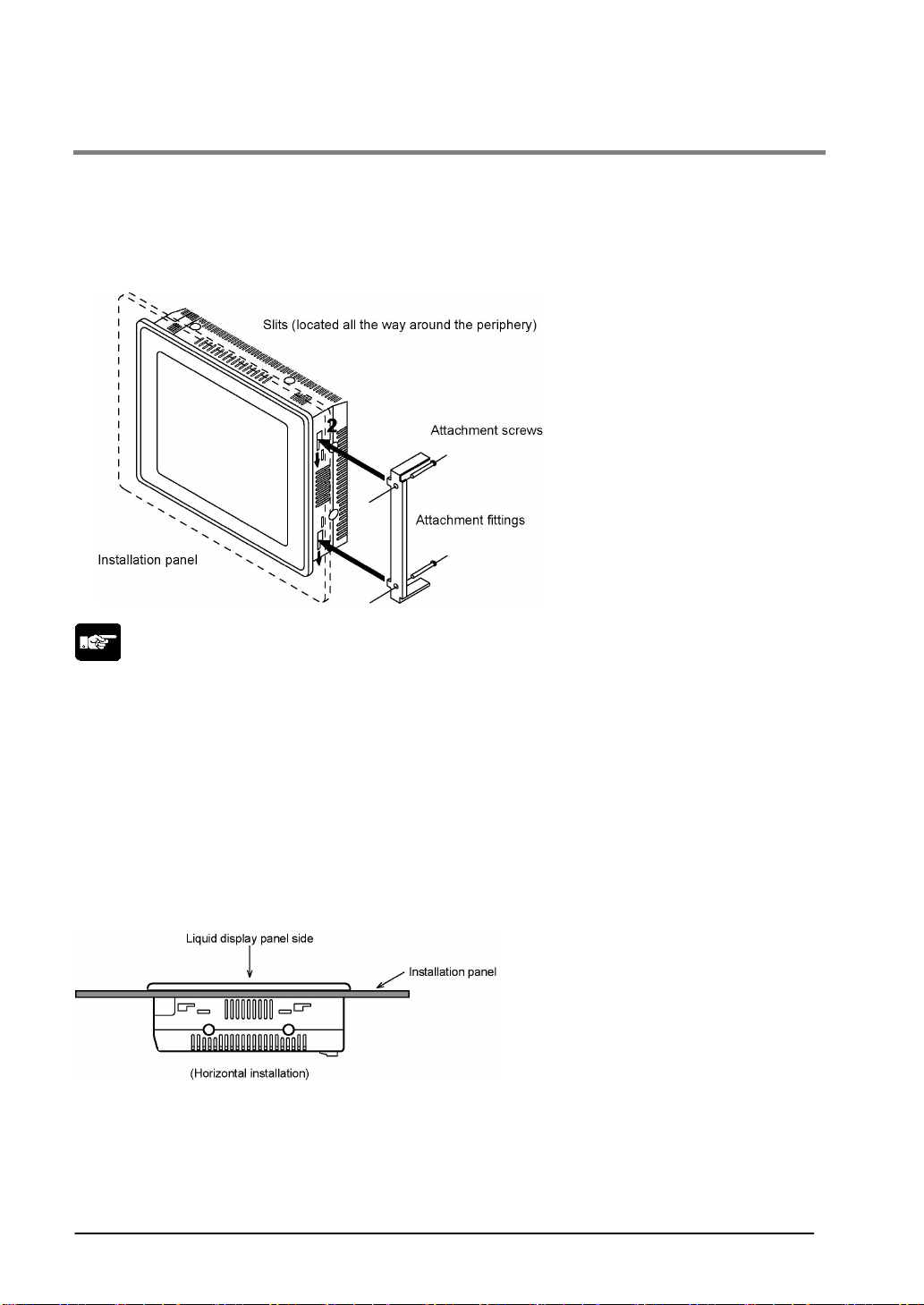
2.1.3 GT30 Installation Method
Secure the GT30 to the installation panel using the two fittings and four screws provided with the unit.
1. Place the GT30 main unit in the installation panel.
2. Insert the fittings into the grooves provided in the GT30 main unit, and tighten the screws to
secure the GT30 main unit to the installation panel.
Note:
Screw tightening torque
The screw tightening torque should be 0.1 N m to 0.25 N m. Tightening the screws too hard can cause
deformation of the front panel, so that the switch will not function properly. Make sure screws are
tightened to the appropriate degree.
Applicable panel thickness
A panel with a thickness of 1.0 to 5.0 mm should be used.
Installation angle and ambient temperature range for usage
If the unit is being installed in a horizontal orientation and the Matsushita Programmer II and C-NET
adaptor are being connected to the TOOL port, please be aware that the ambient usage temperature
should not exceed 40 °C.
Clearance when the GT is installed
When installing the GT30, if other parts are being installed to the panel or cables are being wired to it,
we recommend providing a clearance of 30 to 50 mm around the GT30. This prevents cables from being
damaged, and facilitates the installation work. Also, make sure that the slits in the main unit are never
obstructed.
2-4
Page 49
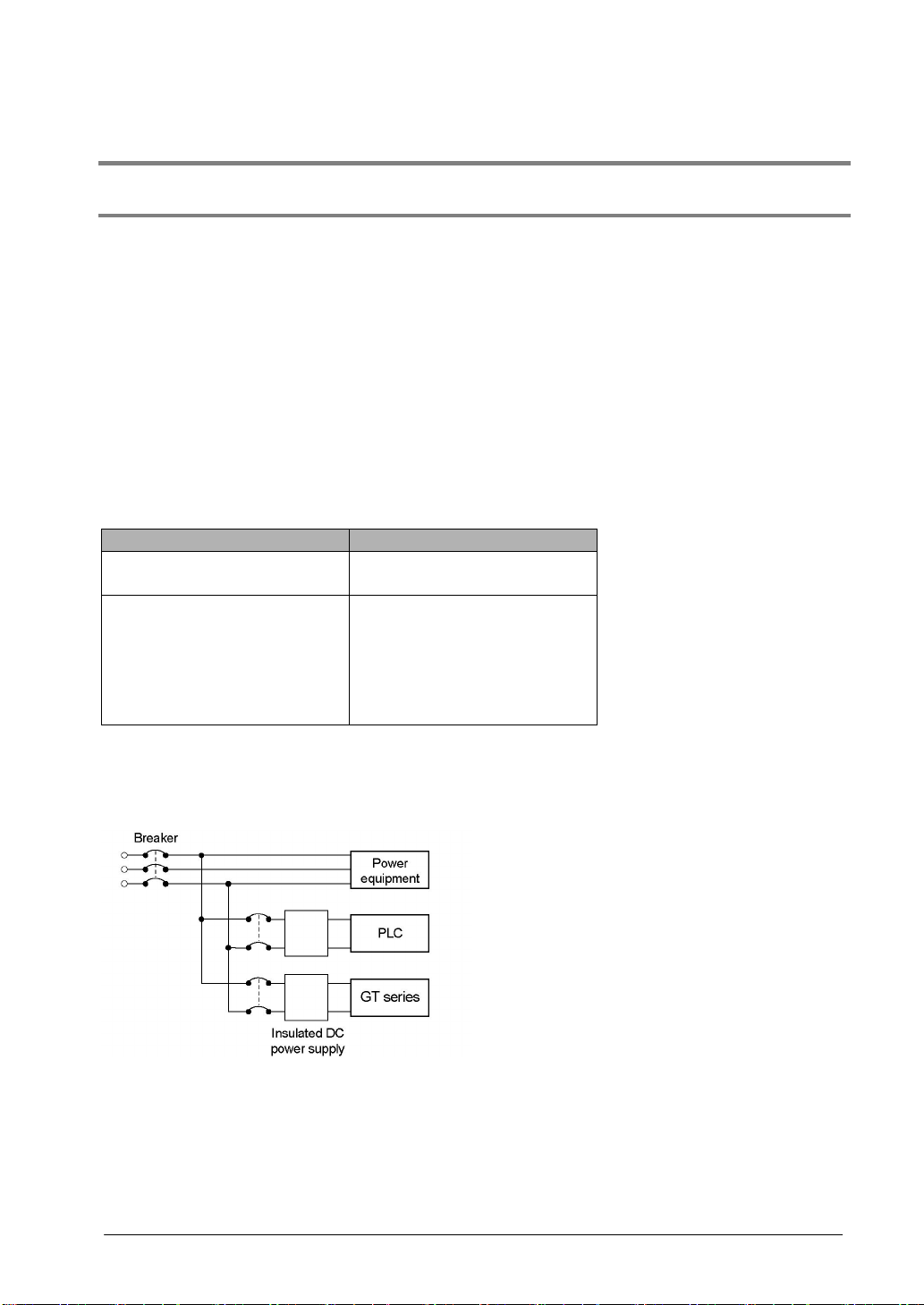
2.2 Wiring the Power Supply
2.2.1 Wiring the Power supply
The power supply should be wired by securely connecting the terminal on the rear of the main
unit to the terminal.
Use twisted wiring for the power supply
In order to minimize influence from noise, the wiring for the power supply should be twisted.
Insulate the power supply inside a protective circuit
• In order to protect the unit against abnormal voltage from the power supply line, the power supply
should be an insulated type, and should be enclosed within a protective circuit.
• A non-insulated requlator is used witht the GT series.
• If a power supply device without an internal protective circuit is being used, power should always be
supplied to the GT series through a fuse or a similar protective device.
Keep the power supply voltage within the operating voltage range
Part No. Operating voltage range
AIGT0030B1/AIGT0030H1
AIGT0032B1/AIGT0032H1
AIGT0030B/AIGT0030H
AIGT0032B/AIGT0032H
AIGT2030B/AIGT2030H
AIGT2032B/AIGT2032H
AIGT3100B/AIGT3100H
AIGT3300B/AIGT3300H
4.5 to 5.5 V DC
21.6 to 26.4 V DC
Keep the power supply wiring separate
• Wiring to the GT series, PLC, and other power equipment should have separate wiring systems.
2-5
Page 50
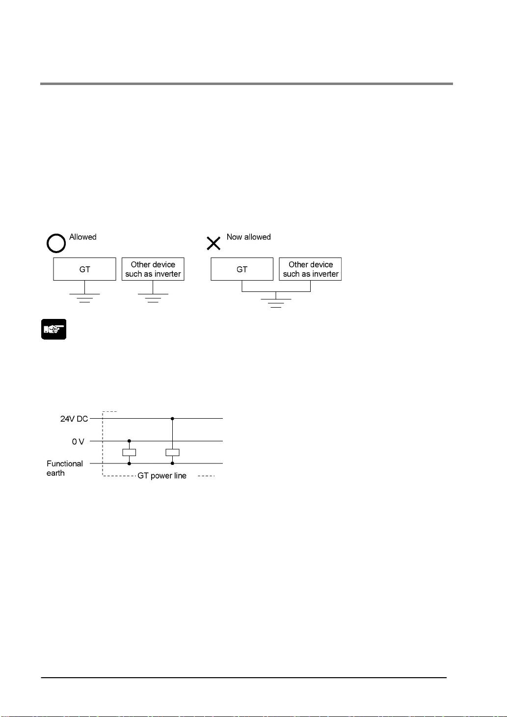
2.2.2 Grounding
Be sure to ground when the influence of noise is great
The unit is tolerant against noise in normal environments, but if the environm ent is particularly
susceptible to noise, please ground.
Use dedicated grounding
• For grounding purposes, use wires with a minimum of 2 mm
2
. The grounding connection should have
a resistance of less than 100 Ω.
• Make the grounding point as close as possible to the GT and keep the distance of the grounding wire
short.
• Sharing the ground with another device may have an adverse effect. Therefore, be sure that grounding
is dedicated.
Note:
Conversely, depending on your environment, grounding may cause a problem.
Example:
Since the power line of the GT unit is connected to a functional earth via electronic parts, the electronic
parts may become damaged if there is an abnormal potential between the power line and the physical
ground.
2-6
Page 51
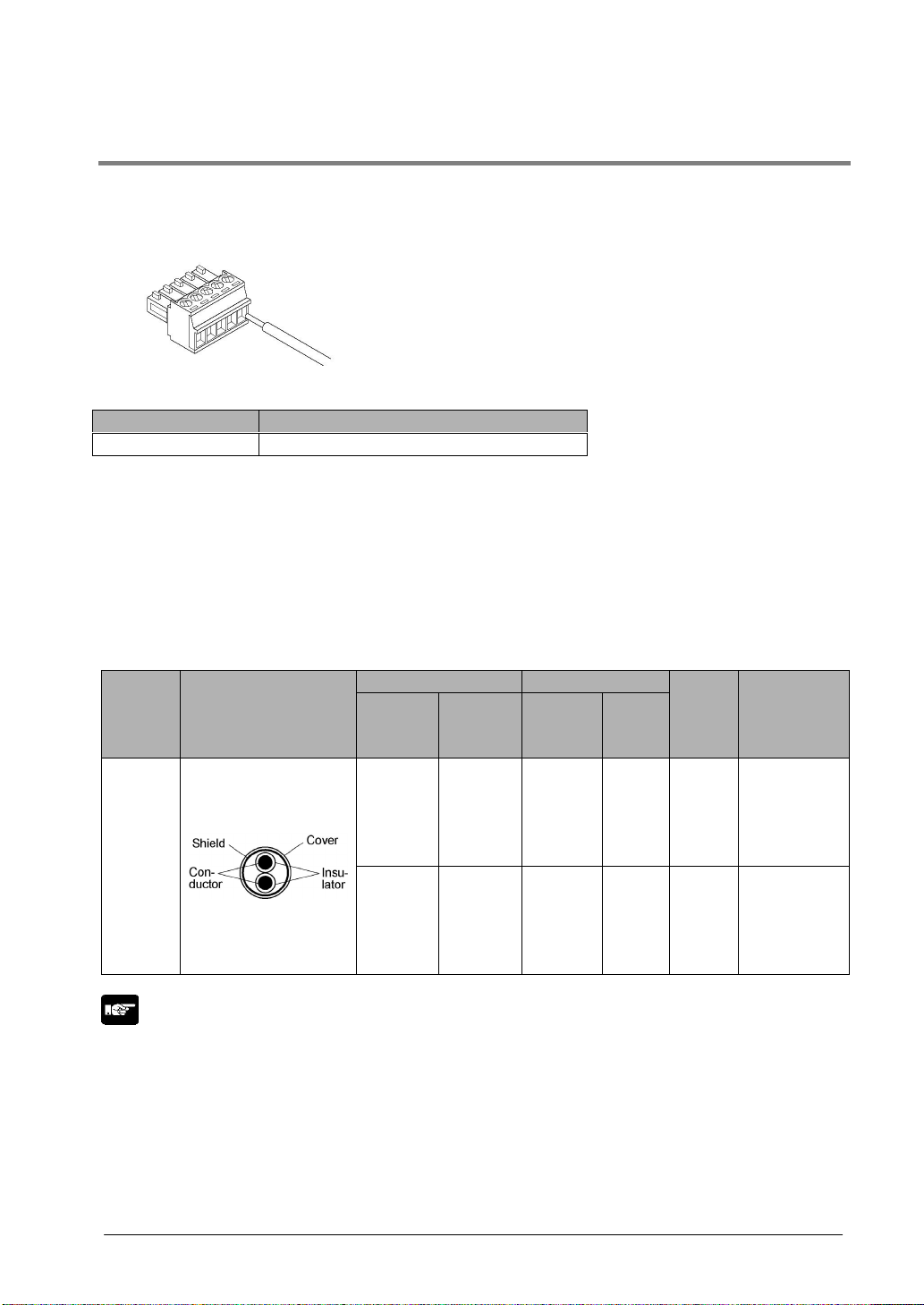
2.3 Wiring the COM. Port
Accessory communication connector/applicable wiring
The communication connector used for the COM. port (provided as an accessory with the main unit) has
a screw-tightening type of terminal block. The wiring shown below should be used.
Applicable wiring (twisted wiring)
Size Conductor cross-section surface area
AWG #28 to 16 0.08 to 1.25 mm
Use a special tool to tighten the terminal block of the communication connector.
Using a screwdriver made by Matsushita Electric Works Co., Ltd. (Product number: AFP0806). The
tightening torque should be 0.22 N m to 0.25 N m or less.
GT01 and GT11: When doing RS485 communication using RS422 type
Please use the following cables or equivalent.
Appropriate electrical cables (twisted cables)
Conductor Insulator
Type
Shielded
twisted
pair
Cross-sectional
view
Size
1.25 mm
(AWG16)
or great er
0.5 mm
(AWG20)
or great er
2
2
2
Resist-
ance
(at 20°°°°C)
Max.
16.8
Ω/km
Max.
33.4
Ω/km
Material
Polye-
thylene
Polye-
thylene
Thick-
ness
Max.
0.5 mm
Max.
0.5 mm
Cable
diam.
Approx.
8.5 mm
Approx.
7.8 mm
Sample
appropriate
cable
Belden 9860
Hitachi Cable,
Ltd. KPEV-
S1.25 mm
Belden 9207
Hitachi Cable,
Ltd. KPEV-
S0.5 mm
1P
1P
2
x
2
x
Note:
• Use shielded twisted pair cables.
• Use only one type of transmission cable. Do not mix more than 1 type.
• When using shielded cable with crossover wiring for the RS485 transmission line, grounded one end.
2-7
Page 52
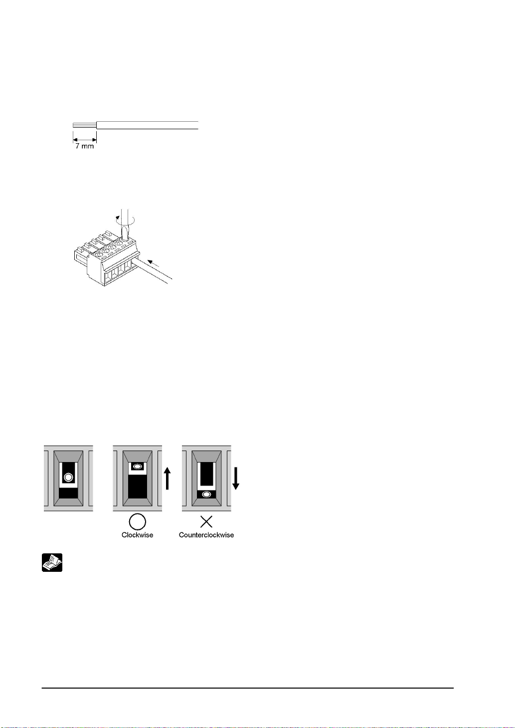
Wiring method
(1) Remove the sheath from the wire.
(2) Insert the wire all the way into the terminal block, and tighten the screw in the clockwise direction to
secure it.
Precautions concerning wiring
The following precautions should be observed, to avoid broken or disconnected wires.
• When removing the sheath, be careful not to scratch the core wire.
• Wire the terminal without twisting the core wire.
• The core wire should be connected without soldering it. Vibration can sometimes cause soldered
connections to break loose.
• After connecting the wiring, avoid subjecting the cable to stress.
• Because of the construction of the terminal, tightenng the wire in the counterclockwise direction will
cause a faulty connection. If this happens, disconnect the wire, check the terminal hole, and connect
the wire again.
Reference:
For information on connecting the COM. port of the GT series with various PLC units, refer to <Chapter 4
Connecting and Communicating with the PLC>.
2-8
Page 53

Chapter 3
Setup
Page 54
3.1 Setup Procedure for the GT
The GT main unit should be set up using the procedure outlined below.
1. Setting the “Configuration File” with GTWIN
The Gthas an internal file called the “Configuration file”, which is used to determine various operating
environment parameters. When the GT is shipped from the factory, the settings listed below are set for
the parameters in the configuration settings file. If changes are made to these settings, they are made
from GTWIN screen creation tool.If the GT is being used without changing the factory settings, the
following setup procedure is not necessary.
Contents of configuration settings for GT when shipped from the factory
Classification Item Setting contents
Basic setup
Communication
parameter
settings
Auto paging
Startup screen
settings.
Other settings
Area for basic
communicaton
with PLC
COM. port
TOOL port
Automatic
paging
Startup screen No. 00
Rise delay time 0 seconds
Backlight control Not turned off automatically
Touch operation
sounds
PLC model: Matsushita Electric Works, Ltd MEWNET-FP series
Word area: DT0 to DT2
Bit area: WR0 to WR2
Baud rate: 9600 bps, data length: 8 bits, stop bit: 1 bit,
parity: odd
<Communication error temporary processing> Retries: 3 tim es,
error code displayed (not held)
Baud rate: 115200 bps, data length: 8 bits, stop bit: 1 bit,
parity: odd
<Through function local setting> None
No
Valid
Always confirm “Basic communication area to PLC” under “Basic Setup”
This is an internal device area that comes already provided in the GT for the purpose of communicating
with a PLC. If the factory settings are to be changed, the setup procedure must be carried out.
Reference: <3.2 Setting the Basic Communication Area Between the GT and PLC>
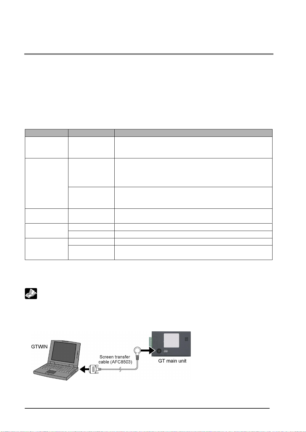
2. Connect the GT and the personal computer
After the settings have been entered with GTWIN, connect the computer and the GT, using the screen
transfer cable.
3-2
Page 55
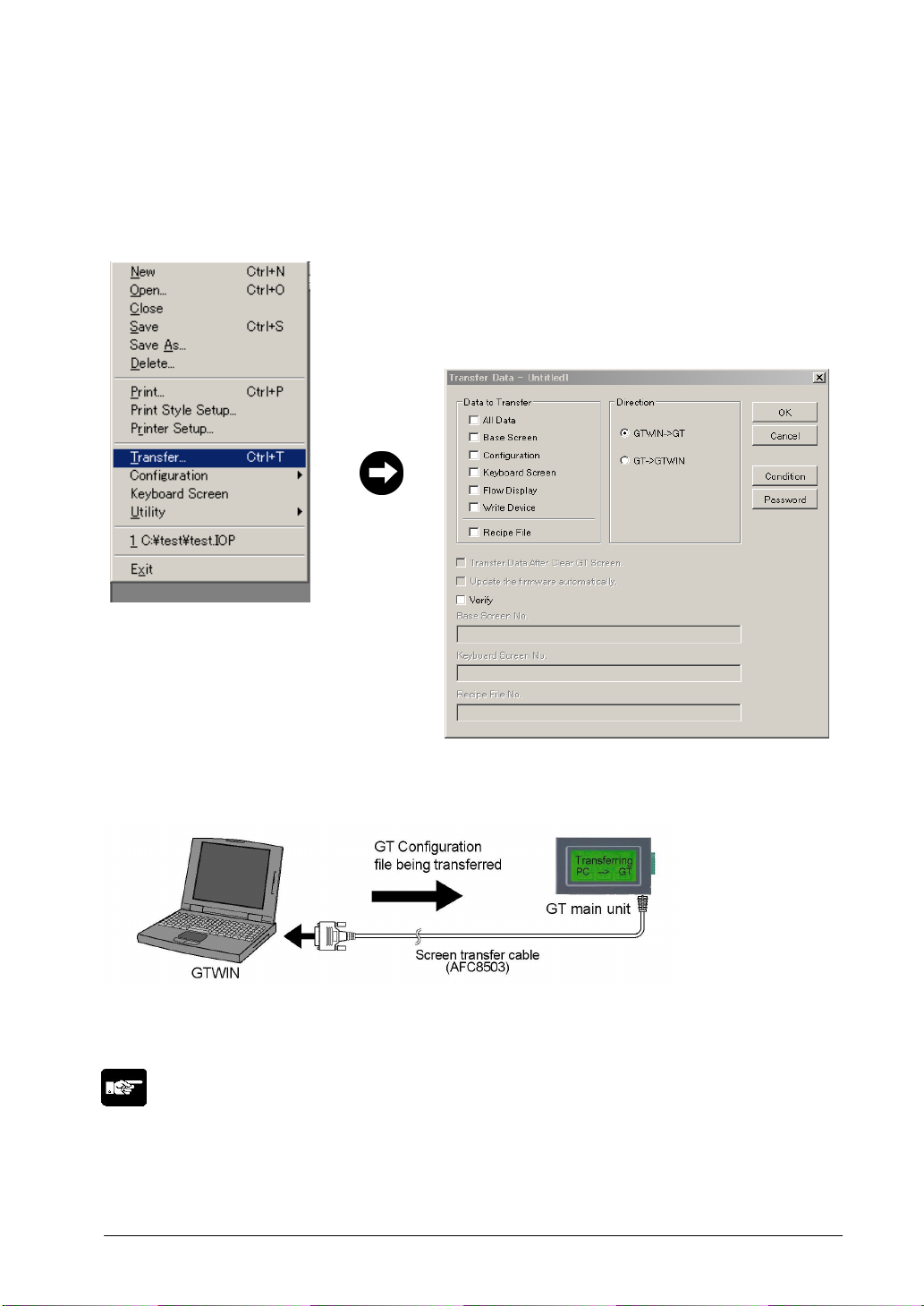
3. Transfer the GT Configuration file from GTWIN
After connections have been completed, use the following procedure to transfer the GT Configuration file
from GTWIN.
• Boot GTWIN, and select
“Transfer” on the “File” menu.
• When the transfer function is selected, a dialog box for
file transfer is displayed. At this point, specify the type of
data to be transferred, and the direction of transfer.
Transfer data: “GT Configuration”
Transfer direction: “GTWIN → GT main unit”
Enter the above conditions and click on the “OK” button.
The system files are transferred to the GT main unit.
When the menu oepration as above is carried out, the configuration file sent to the GT main unit. During
the transfer, a screen like that shown below is displayed.
Setup is completed.
If the transfer has been completed without any problems, the setup is completed.
Note:
• Backup of the GT Configuration file
The GT Configuration file is stored in the user memory (F-ROM) of the GT main unit. This file is deleted
if the memory is initialized using the command on the system menu of the GT main unit, and will have
to be transferred again.
3-3
Page 56
3.2 Setting the Basic Communication Area Between the
GT and PLC
3.2.1 What is the Basic Communication Area?
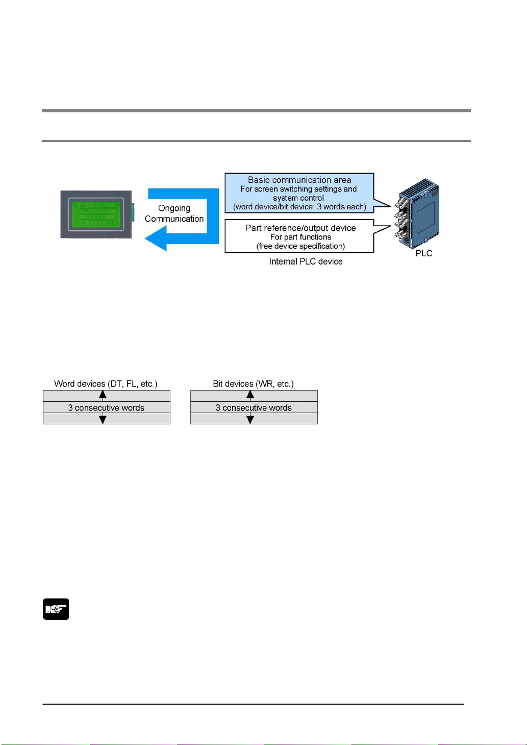
Communication between the GT and PLC is carried out as shown below.
As shown in the illustration, communication is carried out on an ongoing basis between the GT and
internal devices in the PLC. Internal PLC devices are divided into the following two devices:
Basic communication area
This area is for system control, such as screen switching settings. PLC devices belong to this area on a
fixed basis, and communication is constantly being carried out.
Breakdown of the basic communication area
• Word device: For reading devices handled in word units (3 consecutive words)
• Bit device: For reading devices handled in bit units (3 consecutive words)
References and output devices for parts
These are devices that are used in parts functions, and can be freely specified by the user.
Communication is carried out on an ongoing basis only for those that are currently displayed on the
screen and pertain to devices currently in use.
With the GT, before GTWIN screen creation tool is used to specify the devices for parts functions, the
“basic communication area” must be determined.
DT0 to DT2 and WR0 to WR2 are set as the default values for the basic communication area, but the
initial address can be changed using the following procedure.
Note:
The basic communication area should be used in the PLC ladder program to control the GT main unit.
3-4
Page 57
3.2.2 Settings in GTWIN
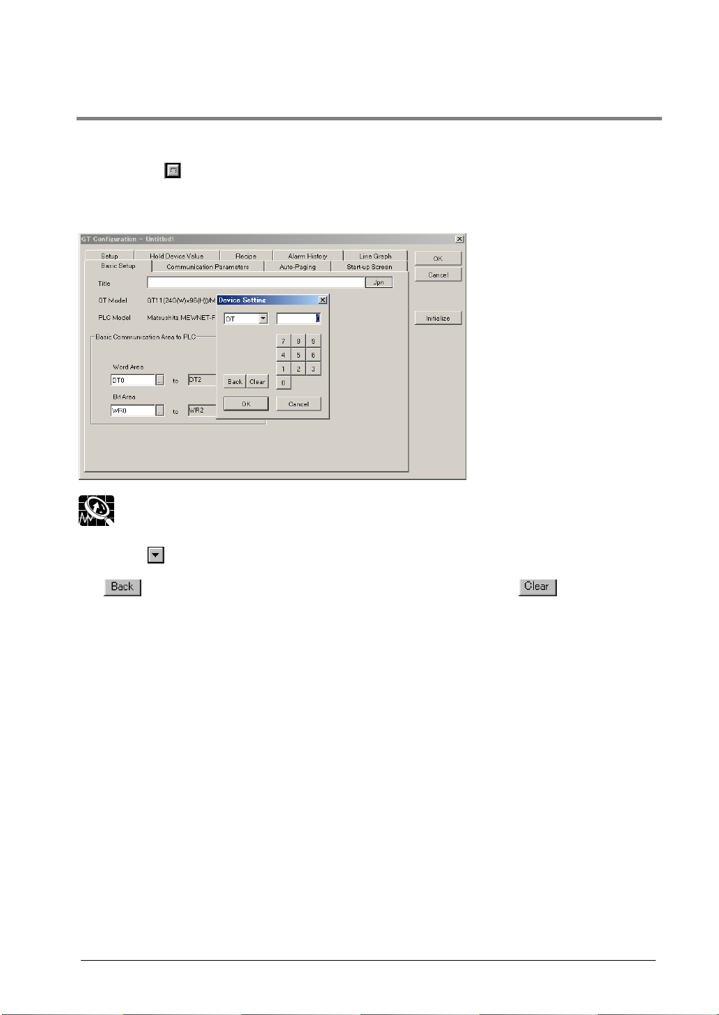
Select “Configuration” under “File” on the menu bar, and then select the sub-menu called “GTWIN
Configuration”. This displays the dialog box for the GT Basic Setup, as shown below.
Clicking on the
shown below, where the initial addresses for the word area and bit area can be changed.
GT Configuration Basic Setup dialog box
button in “Basic Communication Area to PLC” displays the device settings dialog box
Explanation of this function:
Key operaiton in the Device Settings dialog box
Click on the
be entered. Use the ten-keys to enter the address.
The
as a Clear key.
button to display a pull-down menu, and then select the device for which settings are to
button acts as a backspace key when entering an address, and the button functions
3-5
Page 58
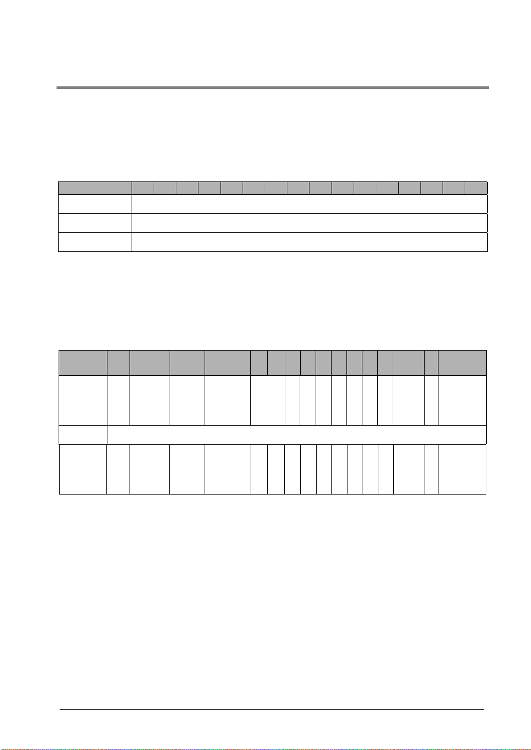
3.2.3 GT01 Basic Communication Area Map
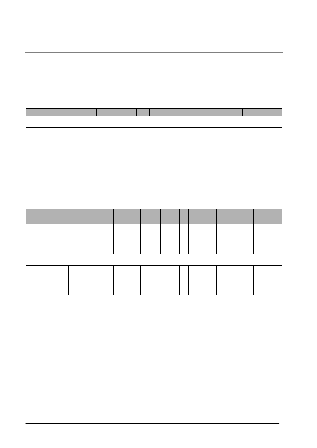
In order for communication to be carried out between the GT01 and PLC, an internal device area like
that shown below is provided in the PLC. This should be used to control the GT main unit through the
PLC ladder program actually being run.
The starting address “N” of the field shown below is specified in the GT configuration settings of GTWIN
screen creation tool, and is then sent to the GT main unit.
Word devices
Word position F E D C B A 9 8 7 6 5 4 3 2 1 0
N+0 Screen No. specified by PLC (area read by GT01 from PLC)
N+1 Usage prohibited
N+2 No. of currently displayed screen (area in which data is written from GT01 to PLC)
Explanation of system area
Screen No. specified by PLC:
No. of currently displayed screen:
Bit devices
Word
position
N+0 BZ
F E D C B A 9 8 7 6 5 4 3 2 1 0
Forced
display
flag
Back-
The screen number specified on the GT01 is specified from the PLC
in hexadecimal format.
The number of the screen currently displayed on the GT01 is written
to the PLC in hexadecimal format.
light
valid
flag
Back-
light
Flashing
Back-
light
Color
N+1 Usage prohibited
N+2
Explanation of system area
BZ:
Forced-display flag:
Backlight Valid flag:
Backlight Flashing:
Backlight Color:
Data Input In Progress flag:
3-6
This turns on the buzzer.
At the rise when the bit is turned on, the screen specifed by the PLC is
forcibly displayed. (This is executed only when at the rise of the bit.)
When the bit is turned on, the backlight flashing/backlight color control
becomes effective.
0: Lighted (normal), 1: Flashing
00: Off, 01: Green, 10: Red, 11: Orange
This is 1 while data is being input, and 0 when data input has been
completed.
Data
Input in
Progress
flag
Page 59
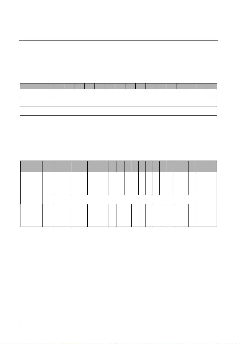
3.2.4 GT11 Basic Communication Area Map
In order for communication to be carried out between the GT11 and PLC, an internal device area like
that shown below is provided in the PLC. This should be used to control the GT main unit through the
PLC ladder program actually being run.
The starting address “N” of the field shown below is specified in the GT configuration settings of GTWIN
screen creation tool, and is then sent to the GT main unit.
Word devices
Word position F E D C B A 9 8 7 6 5 4 3 2 1 0
N+0 Screen No. specified by PLC (area read by GT11 from PLC)
N+1 Usage prohibited
N+2 No. of currently displayed screen (area in which data is written from GT01 to PLC)
Explanation of system area
Screen No. specified by PLC:
No. of currently displayed screen:
Bit devices
Word
position
N+0 BZ
F E D C B A 9 8 7 6 5 4 3 2 1 0
Forced
display
flag
The screen number specified on the GT11is specified from the PLC
in hexadecimal format.
The number of the screen currently displayed on the GT11 is written
to the PLC in hexadecimal format.
Back-
light
valid
flag
Back-
light
Flashing
Back-
light
Color
N+1 Usage prohibited
N+2
Explanation of system area
BZ:
Forced-display flag:
Backlight Valid flag:
Backlight Flashing:
Backlight Color:
Data Input In Progress flag:
BAT:
BAT LOW flag:
This turns on the buzzer.
At the rise when the bit is turned on, the screen specifed by the PLC is
forcibly displayed. (This is executed only when at the rise of the bit.)
When the bit is turned on, the backlight flashing/backlight color control
becomes effective.
0: Lighted (normal), 1: Flashing
00: Off, 01: Green, 10: Red, 11: Orange
This is 1 while data is being input, and 0 when data input has been
completed.
This goes on if clock data and Hold PLC Device data held in the SRAM
are not being backed up normally. (This bit also goes on if the SRAM is
not backed up by the internal secondary battery.)
This goes on when the battery is running low. Please replace the battery
with a new one within a week after this bit went on.
BAT
LOW
flag
B
A
Progress
T
Data
Input in
flag
3-7
Page 60
3.2.5 GT30 Basic Communication Area Map
In order for communication to be carried out between the GT30 and PLC, an internal device area like
that shown below is provided in the PLC. This should be used to control the GT main unit through the
PLC ladder program actually being run.
The starting address “N” of the field shown below is specified in the GT configuration settings of GTWIN
screen creation tool, and is then sent to the GT main unit.
Word devices
Word position F E D C B A 9 8 7 6 5 4 3 2 1 0
N+0 Screen No. specified by PLC (area read by GT30 from PLC)
N+1 Usage prohibited
N+2 No. of currently displayed screen (area in which data is written from GT30 to PLC)
Explanation of system area
Screen No. specified by PLC:
No. of currently displayed screen:
Bit devices
Word
position
N+0 BZ
F E D C B A 9 8 7 6 5 4 3 2 1 0
Forced
display
flag
The screen number specified on the GT30 is specified from the PLC
in hexadecimal format.
The number of the screen currently displayed on the GT30 is written
to the PLC in hexadecimal format.
Back-
light
valid
flag
Back-
light
Flashing
Back-
light
Color
N+1 Usage prohibited
N+2
Explanation of system area
BZ:
Forced-display flag:
Backlight Valid flag:
Backlight Flashing
Backlight Color:
Data Input In Progress flag:
BAT:
BAT LOW flag:
3-8
This turns on the buzzer.
At the rise when the bit is turned on, the screen specifed by the PLC is
forcibly displayed. (This is executed only when at the rise of the bit.)
When the bit is turned on, the backlight flashing/backlight color control
becomes effective.
0: Lighted (normal), 1: Flashing
00: Off, 01: Lighted, 10: Lighted, 11: Lighted
This is 1 while data is being input, and 0 whendata input has been
completed.
This goes on if clock data and Hold PLC Device data held in the SRAM
are not being backed up normally. (This bit also goes on if the SRAM is
not backed up by the internal secondary battery.)
This goes on when the battery is running low. Please replace the battery
with a new one within a week after this bit went on.
BAT
LOW
flag
B
A
Progress
T
Data
Input in
flag
Page 61

Chapter 4
Connecting and Communicating with the
PLC
Page 62
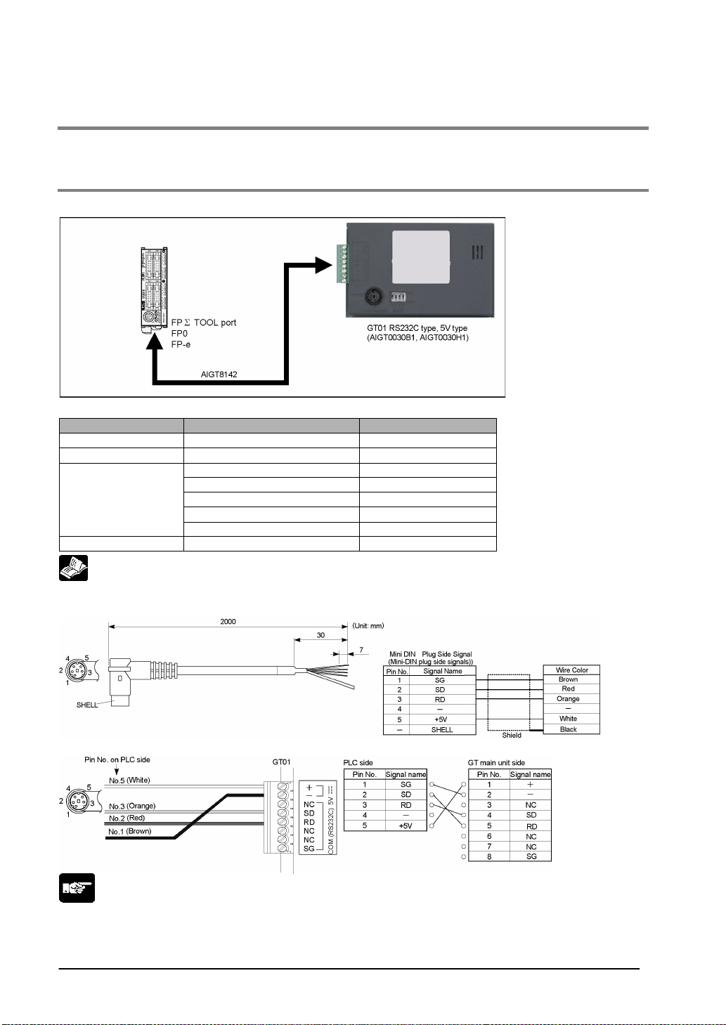
4.1 Connecting GT01/GT11 with PLC
4.1.1 Connecting to the TOOL port of FPΣΣΣΣ / FP0 / FP-e (1) (Direct Connection to
GT01)
Connecting to the TOOL port
FPΣΣΣΣ communication format settings
System register No. Item Value set
410 TOOL port unit number 1
412 Modem connection No modem connection
Data length 8 bits
Parity c h ec k Yes, Odd
413
415 COM. port 1 Baud rate setting 9600 bps
Stop bits 1 bit
End code CR (Fixed)
Start code No STX (Fixed)
Reference: <4.1.15 How to Make Communication Settings Using the FPWIN GR>
PLC communication cable: Mini-DIN 5-pin loose-wire cable (AIGT8142)
Connecting to the FPΣΣΣΣ/FP0/FP-e TOOL port
Note:
• Keep the cable no longer than 3 m.
• In case of connecting to PLC with all expansion slots used, prepare an external 5 V DC power supply
for the GT01 due to current consumption limits.
4-2
Page 63
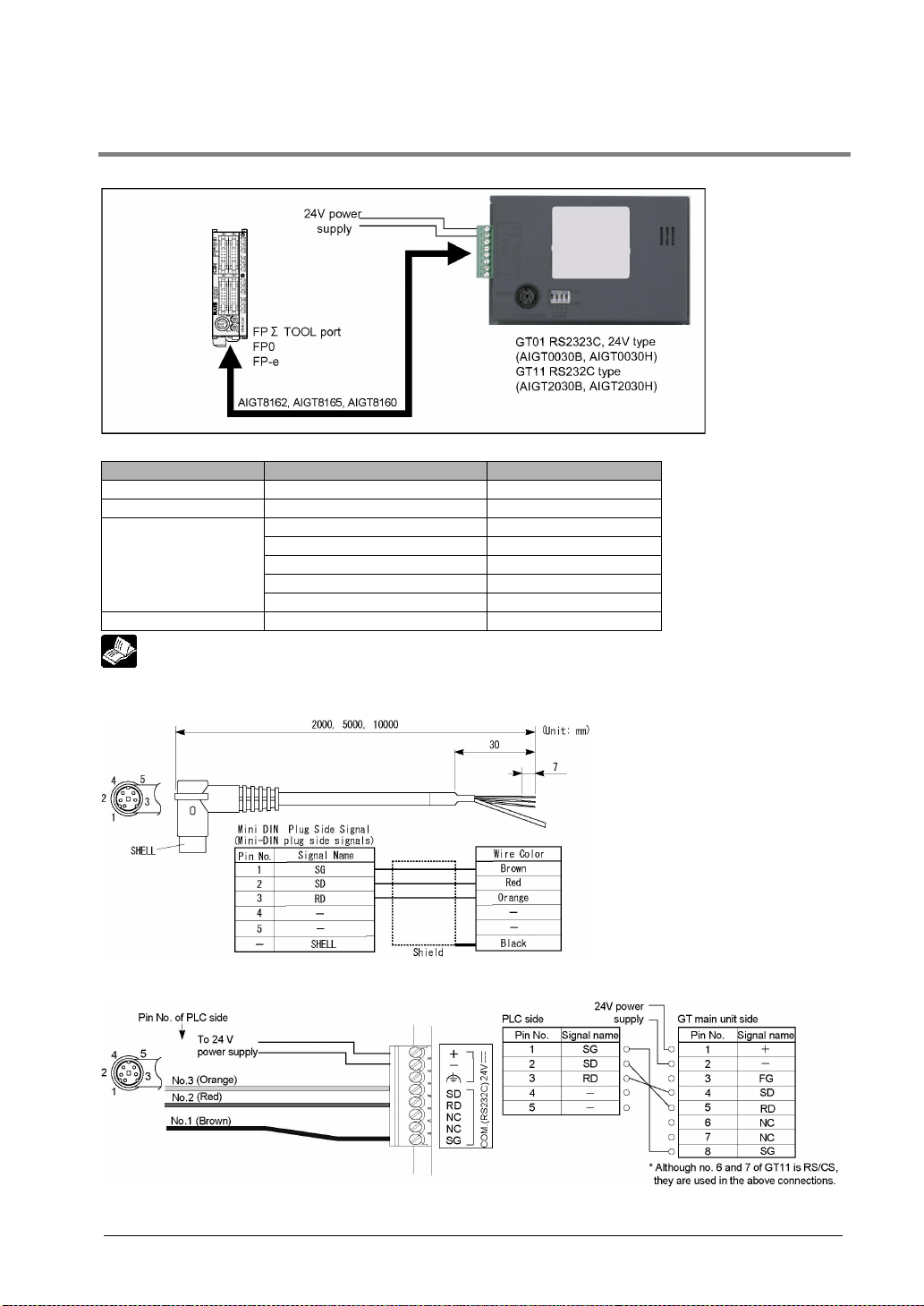
4.1.2 Connecting to the TOOL port of FPΣΣΣΣ / FP0 / FP-e (2)
Connecting to the TOOL port
FPΣΣΣΣ communication format settings
System register No. Item Value set
410 TOOL port unit number 1
412 Modem connection No modem connection
Data length 8 bits
Parity c h ec k Yes, Odd
413
415 COM. port 1 Baud rate s etting 9600 bps
Stop bits 1 bit
End code CR (Fixed)
Start code No STX (Fixed)
Reference: <4.1.15 How to Make Communication Settings Using the FPWIN GR>
PLC communication cable: Mini-DIN 5-pin loose-wire cable (AIGT8162, AIGT8165, AIGT8160)
Connecting to the FPΣΣΣΣ/FP0/FP-e TOOL port
4-3
Page 64
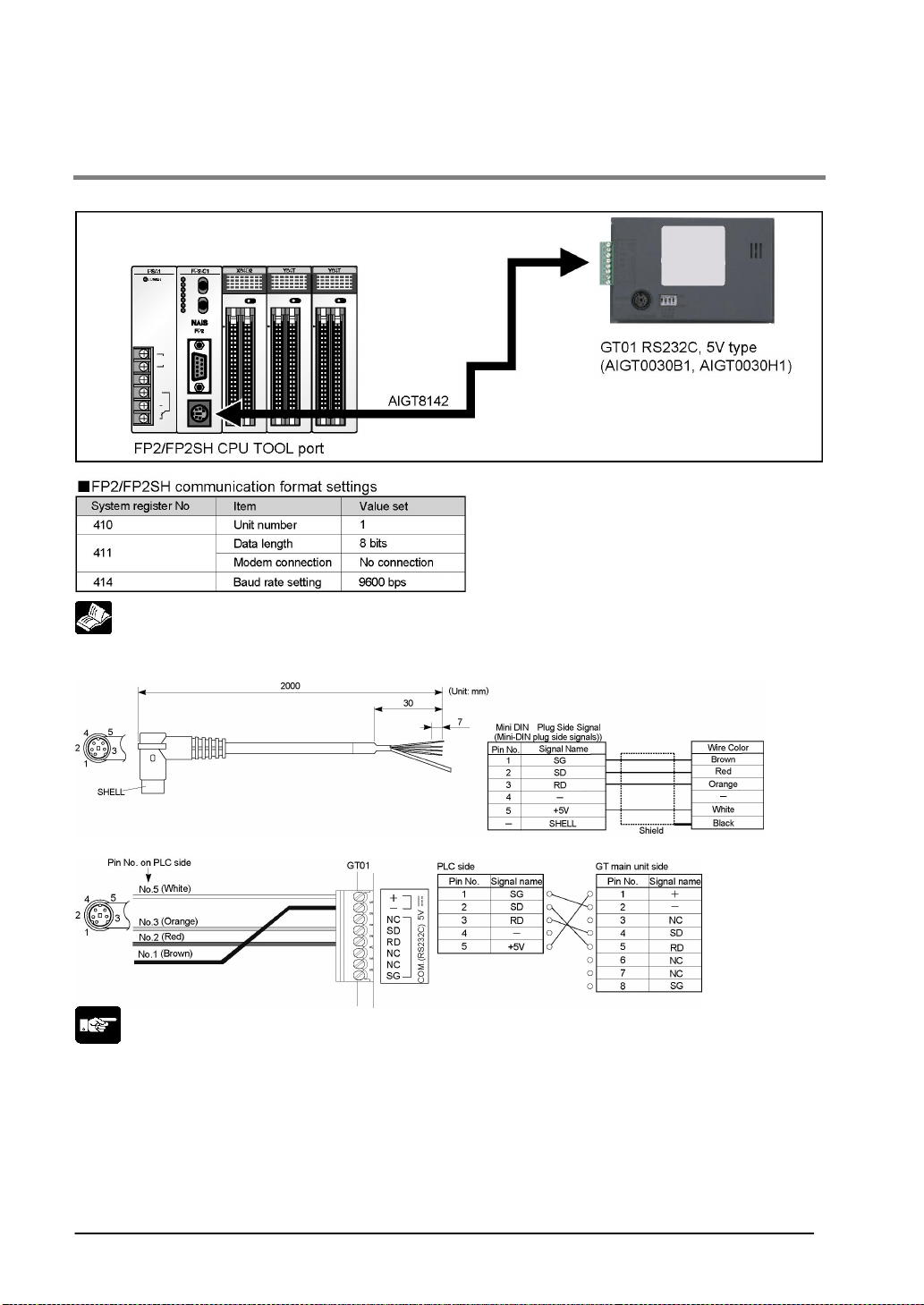
4.1.3 Connecting to the TOOL port of FP2 / FP2SH (1) (Direct Connection to
GT01)
Connecting to the TOOL port
Reference: <4.1.15 How to Make Communication Settings Using the FPWIN GR>
PLC communication cable: Mini-DIN 5-pin loose-wire cable (AIGT8142)
Connecting to the FP2/FP2SH TOOL port
Note:
• Keep the cable no longer than 3 m.
• When supplying power from the TOOL port, verify whether or not it will be possible by using the
method of calculation for the number of expansion units that is provided in the hardware manual.
4-4
Page 65
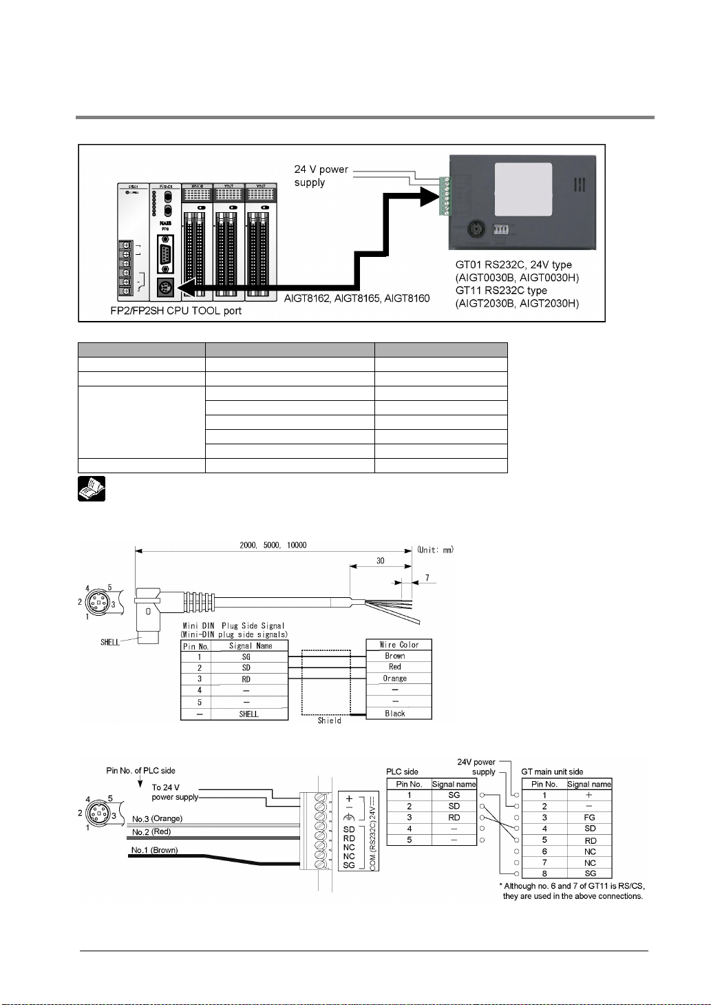
4.1.4 Connecting to the TOOL port of FP2 / FP2SH (2)
Connecting to the TOOL port
FPΣΣΣΣ communication format settings
System register No. Item Value set
410 TOOL port unit number 1
412 Modem connection No modem connection
Data length 8 bits
Parity c h ec k Yes , Odd
413
415 COM. port 1 Baud rate setting 9600 bps
Reference: <4.1.15 How to Make Communication Settings Using the FPWIN GR>
Stop bits 1 bit
End code CR (Fixed)
Start code No STX (Fixed)
PLC communication cable: Mini-DIN 5-pin loose-wire cable (AIGT8162, AIGT8165, AIGT8160)
Connecting to the FP2/FP2SH TOOL port
4-5
Page 66
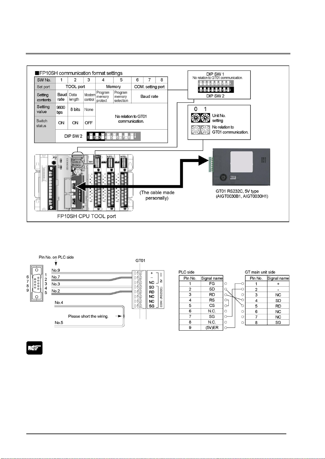
4.1.5 Connecting to the TOOL port of FP10SH (1) (Direct Connection to GT01)
Connecting to the TOOL port
Connecting to the FP10SH TOOL port
Please create a cable from the following contents.
Note:
• Keep the cable no longer than 3 m.
• When supplying power from the TOOL port, verify whether or not it will be possible by using the
method of calculation for the number of expansion units that is provided in the FP10SH manual.
4-6
Page 67
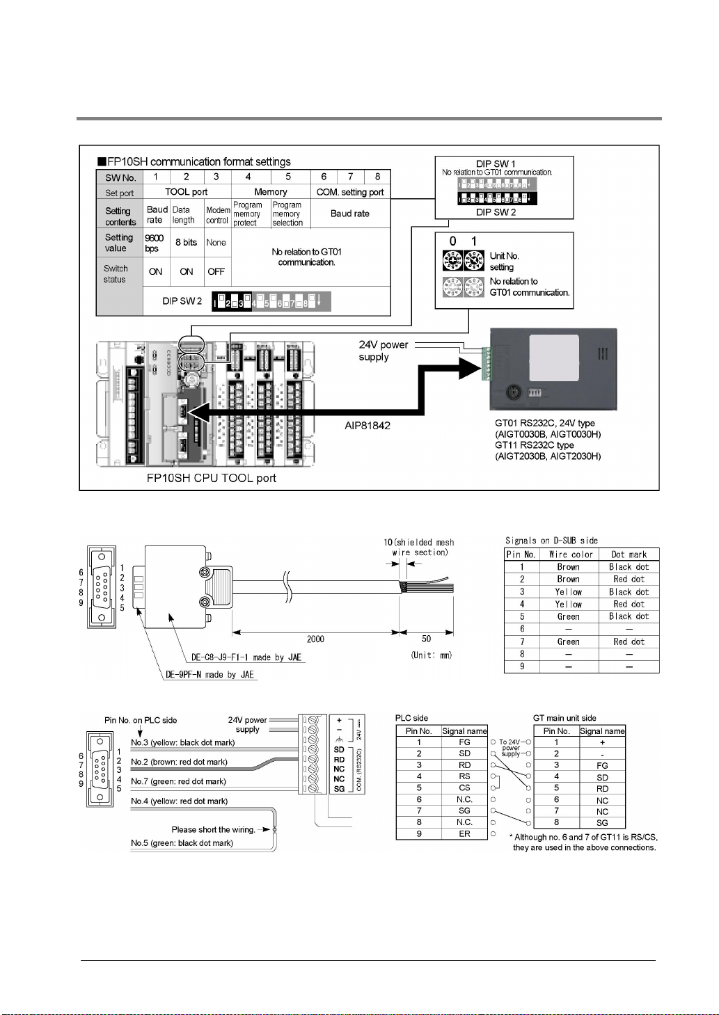
4.1.6 Connecting to the TOOL port of FP10SH (2)
Connecting to the TOOL port
PLC communication cable: D-SUB 9-pin loose-wire cable (AIP81842)
Connecting to the FP10SH COM. port
4-7
Page 68

4.1.7 Connecting to the TOOL port of FP-M (1) (Direct Connection to GT01)
Connecting to the TOOL port
PLC communication cable: Mini-DIN 5-pin loose-wire cable (AIGT8142)
Connecting to the FP-M TOOL port
Note:
• Keep the cable no longer than 3 m.
• Use an external power supply for the GT01 when connecting to the TOOL port of a fully expanded
control unit.
4-8
Page 69
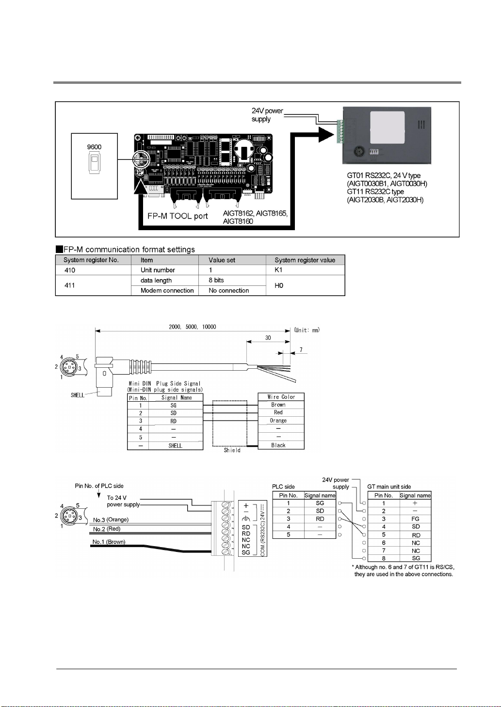
4.1.8 Connecting to the TOOL port of FP-M (2)
Connecting to the TOOL port
PLC communication cable: Mini-DIN 5-pin loose-wire cable (AIGT8162, AIGT8165, AIGT8160)
Connecting to the FP-M TOOL port
4-9
Page 70
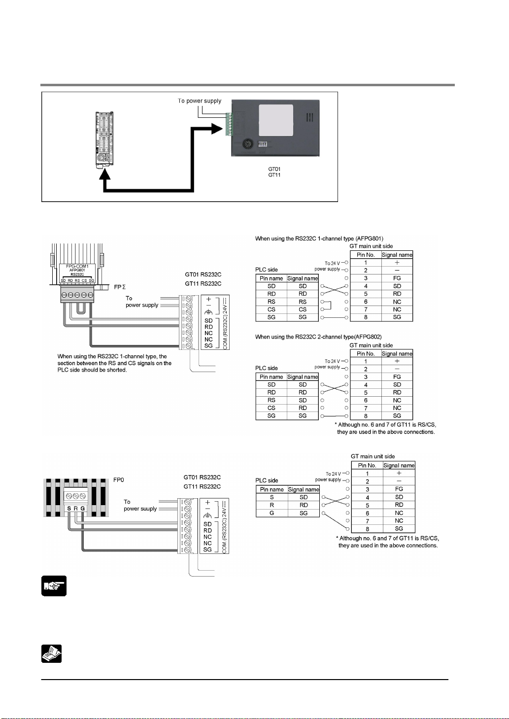
4.1.9 Connecting to the COM. port of FPΣΣΣΣ / FP0 / FP-e
Connecting to the FPΣΣΣΣ COM. 1 and COM. 2 cassettes
Connecting to the FPΣΣΣΣ COM. port
Connecting to the FP0 COM. port
Note:
• We do not provide a dedicated cable for hard wiring to the FP0 COM port. Please provide your own
cable. If you provide a cable for this purpose, please note the following.
• Please use AWG #28 to 16 size shielded cable (with a conductor cross sectional area of 0.08 to 1.25
2
mm
).
Reference: <4.1.15 How to Make Communication Settings Using the FPWIN GR>
4-10
Page 71
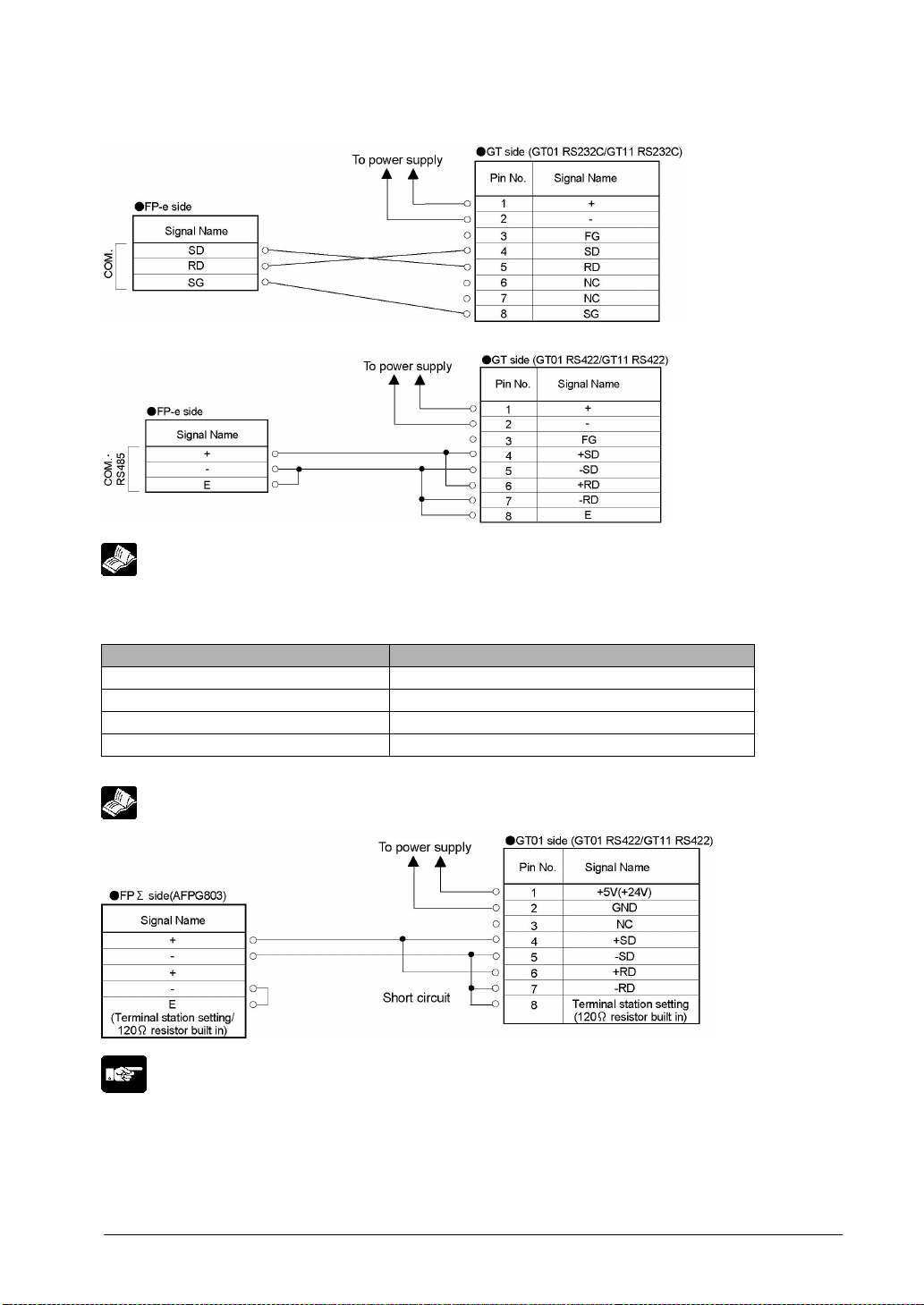
Connecting to the FP-e (RS232C)
Connecting to the FP-e (RS485)
Reference: <FP-e User’s Manual ARCT1F369>
Connecting to the FPΣΣΣΣ COM. 3 cassette
FPΣΣΣΣ communication format settings
Item Value set
COM. port 1 unit number No. 1
COM. port 1 communication mode Computer link
COM. port 1 transfer format 8 bits, odd, 1 stop, terminal CR (fixed), no STX
COM. port 1 baud rate setting 38400 bps, 57600 bps, 115200 bps
Note) Use a baud rate of 38400 bps or higher.
Reference: <4.1.15 How to Make Communication Settings Using the FPWIN GR>
Note:
• Use with 1:1.
• If noise is a problem, use a shielded cable and employ countermeasures such as installing a ferrite
core if necessary.
• The transferdistance is 30 m maximum. (Up to 500 m is possible with the 24 V type).
• Any port other than COM3 cannot be used when communicating with an FPΣ using RS485.
4-11
Page 72
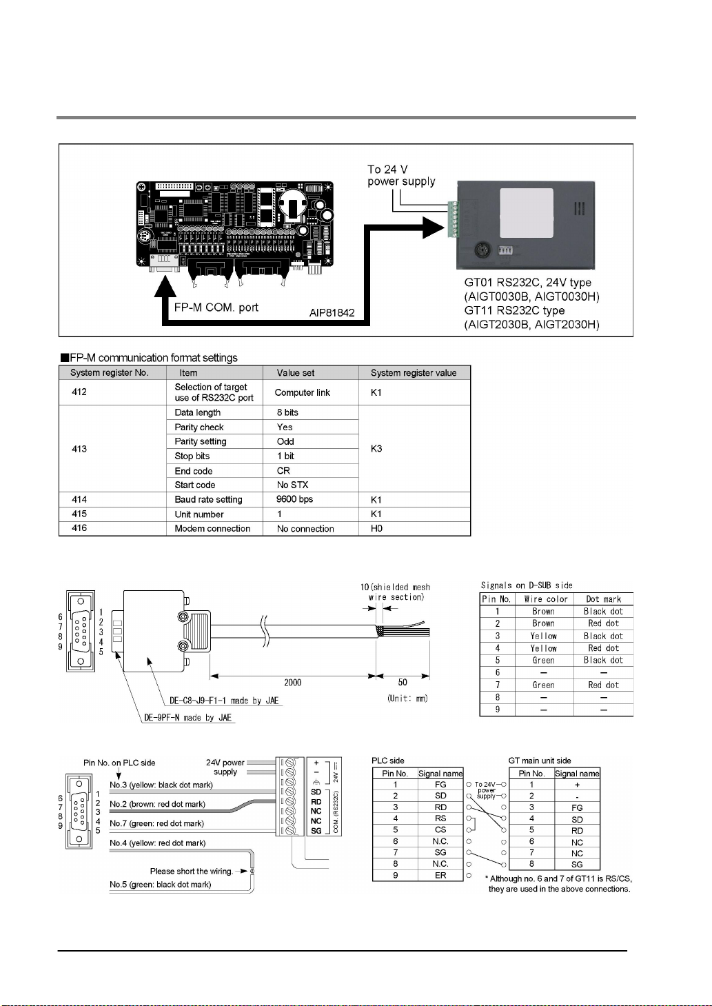
4.1.10 Connecting to the COM port of FP1 / FP2SH / FP-M
Connecting to the COM port
PLC communication cable: D-SUB 9-pin loose-wire cable (AIP81842)
Connecting to the FP-M COM. port
4-12
Page 73
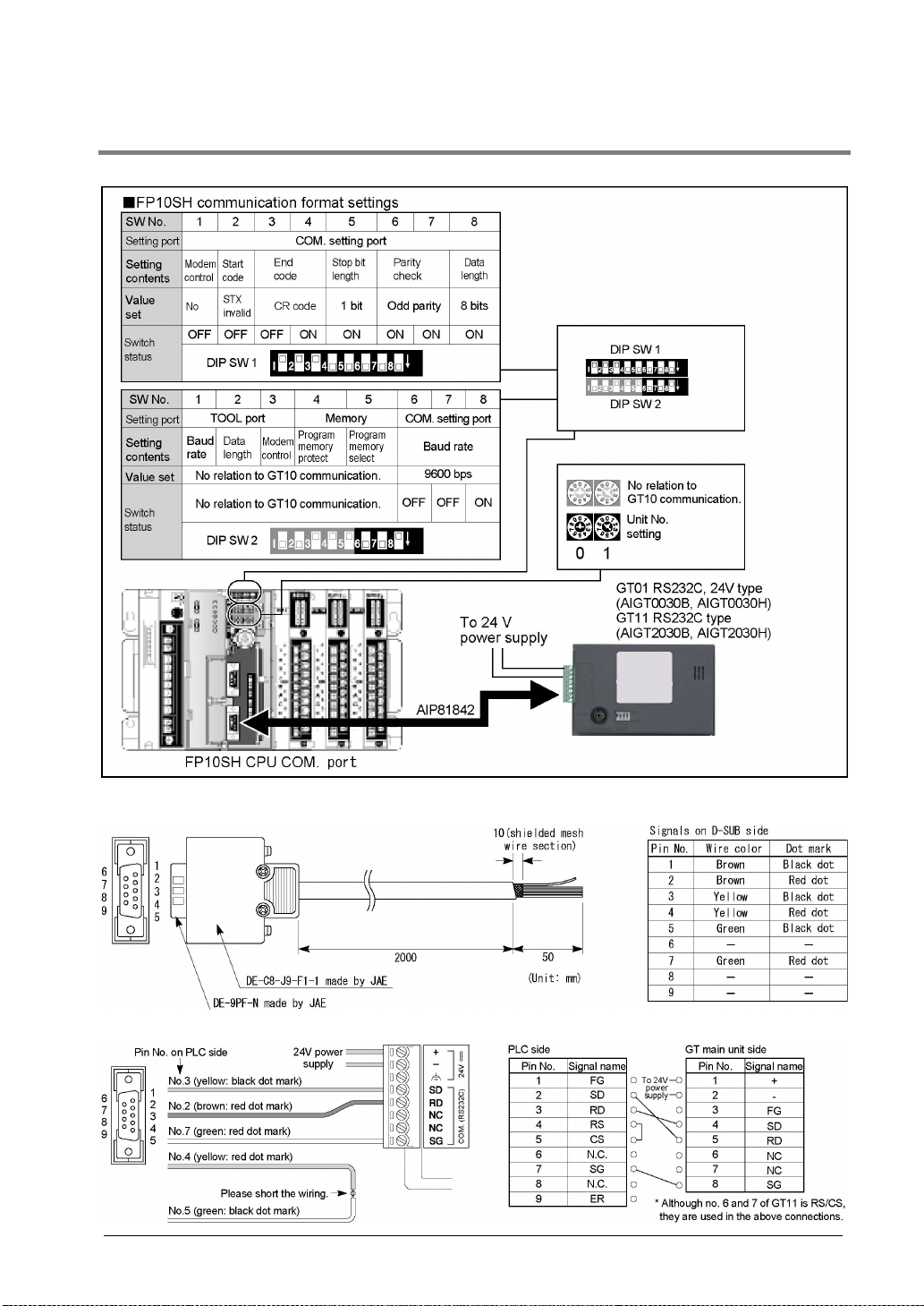
4.1.11 Connecting to the COM port of FP10SH
Connecting to the COM port
PLC communication cable: D-SUB 9-pin loose-wire cable (AIP81842)
Connecting to the FP10SH COM. port
4-13
Page 74
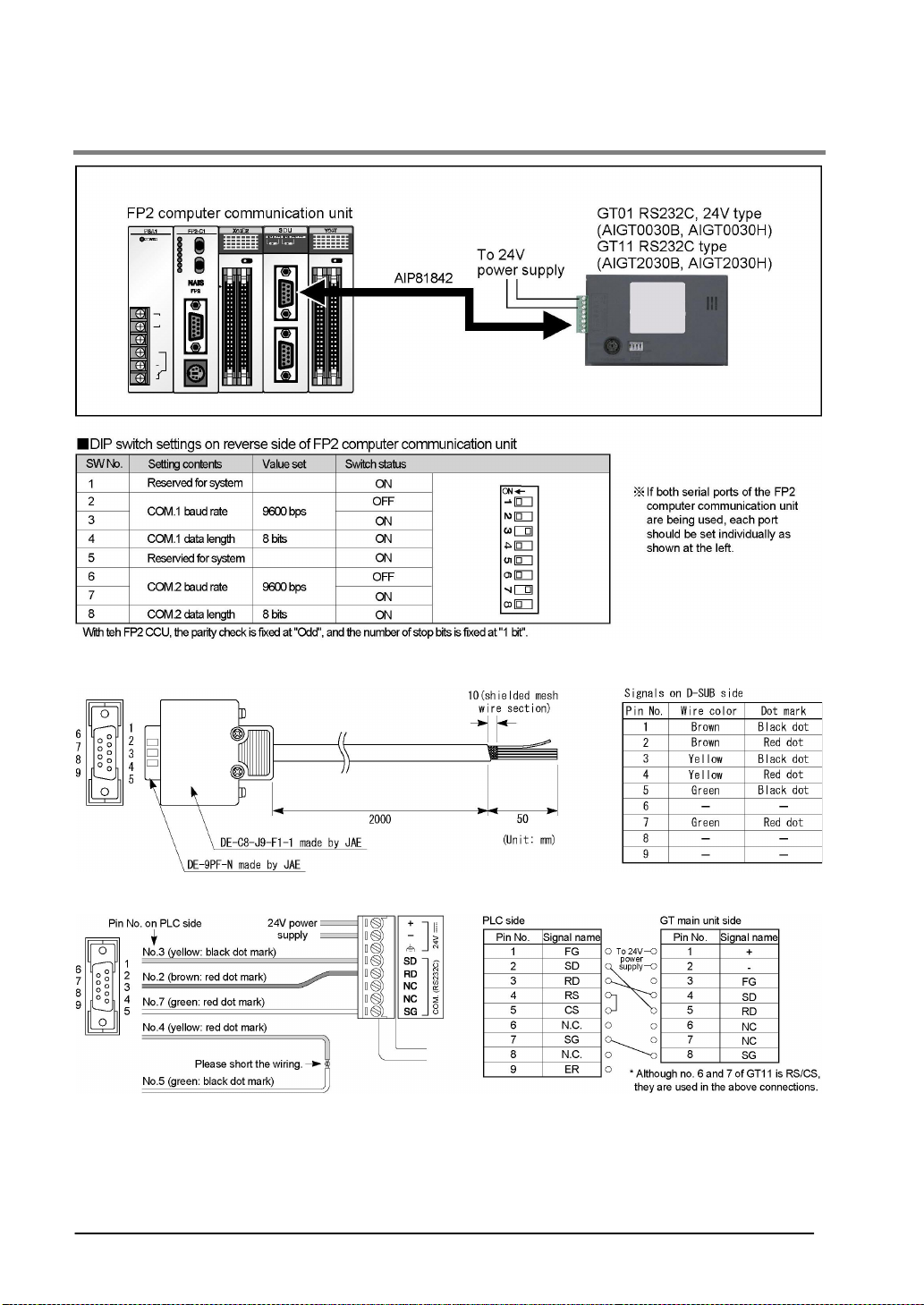
4.1.12 Connecting to the FP2 / FP2SH Computer Communication Unit
PLC communication cable: D-SUB 9-pin loose-wire cable (AIP81842)
Connecting to the FP2 computer communication unit (CCU)
4-14
Page 75
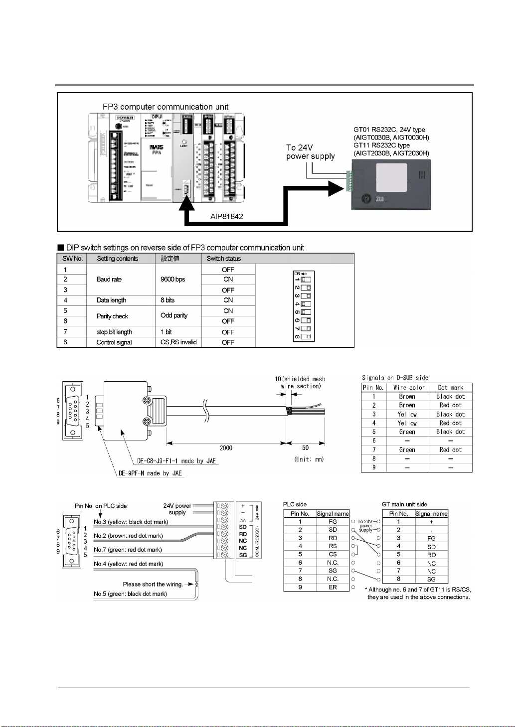
4.1.13 Connecting to the FP10SH / FP3 Computer Communication Unit
PLC communication cable: D-SUB 9-pin loose-wire cable (AIP81842)
Connecting to the FP3 computer communication unit (CCU)
4-15
Page 76
4.1.14 Cautions Regarding Direct Connection of GT01 (5V DC type) to the FP
Series TOOL Port
When directly connecting a GT01 to an FP Series TOOL port, a limit will apply to the number of units that
can be expanded due to the capacity of the FP Series power supply. Please proceed in accordance with
the information given below.
FP Series type Limitations when connecting a GT01
FP0 Maximum of two expansion units *
FPΣ Maximum of six expansion units *
FP2
FP2SH
FP10SH
FP-M Maximum of three expansion units *
FP-e There are no particular restrictions.
* Expansion is possible with the number of units given above, regardless of the type of unit.
* Please perform connections with the power turned off.
The method for calculating the number fo units that can be expanded is
provided in the control unit hardware manual. Follow that formula and keep
the GT01’s power consumption noghigher than 200 mA when calculating.
4-16
Page 77
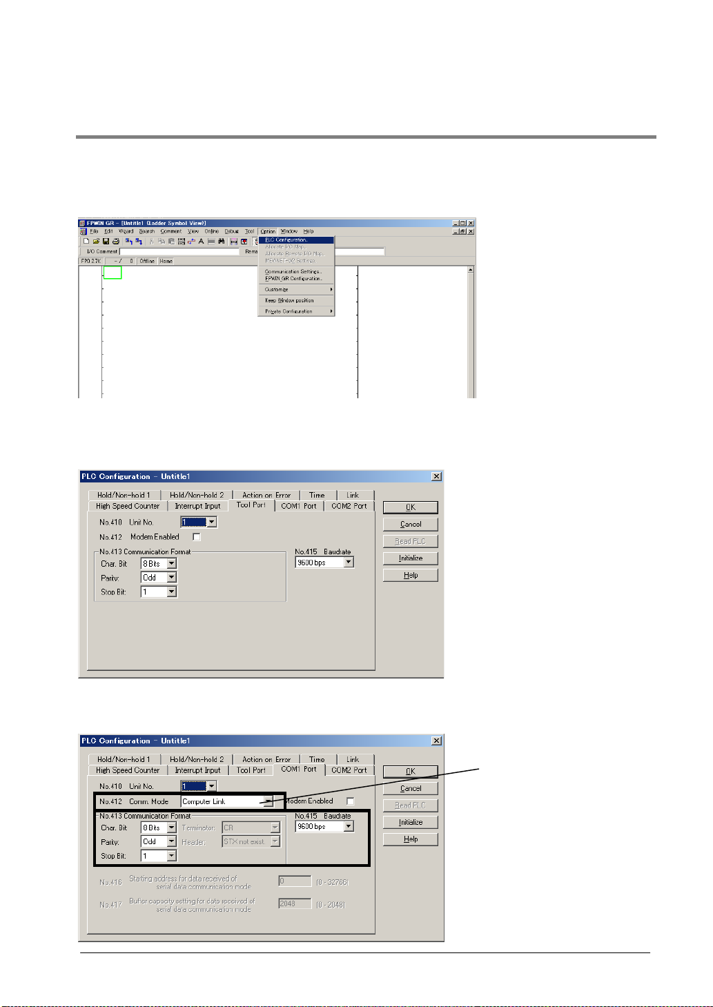
4.1.15 How to Make Communication Settings Using the FPWIN GR and FPWIN
Pro
FPWIN GR
Please read below to make PLC communication settings using the FPWIN GR.
1. Select “PLC system register setting” from the Option menu (O).
2. The window below will be displayed.
Select “Tool port setting” when connecting to the tool port or “COM port setting” when connecting to the
COM port. Please match the transfer format and transmission speed settings to those of the GT.
In addition to the transfer format and transmission speed settings, set the communication mode to
“Computer link” when using the COM port.
Select “Computer Link”.
4-17
Page 78
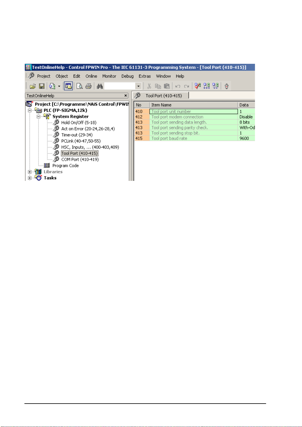
FPWIN Pro
To make communication settings in FPWIN Pro in the Project Navigator: PLC→System Register→Tool
Port.
For details, please refer to the online help.
4-18
Page 79
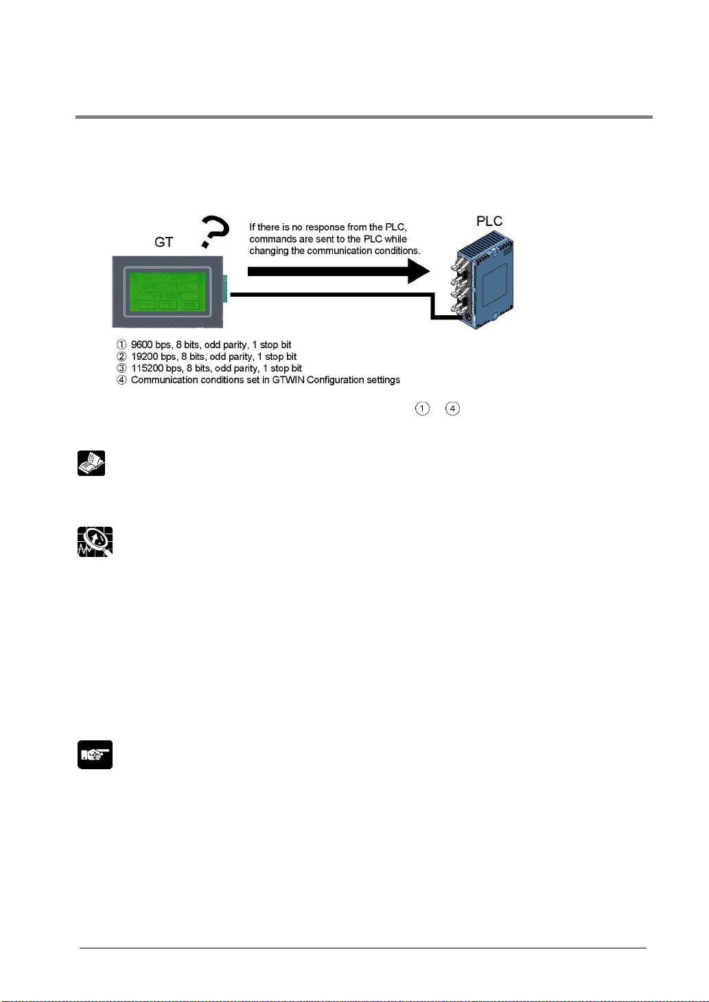
4.1.16 Automatic Communication Settings Function
After turning on the power supply, if there is not response from the PLC connected to the GT, the GT
switches to the automatic setting mode for the communication conditions. In the automatic setting mode,
commands are sent to the PLC while changing the communication conditions in the sequence shown
below.
The GT, in automatic setting mode, continues to repeat steps to until there is a response from the
PLC. While it is repeating there steps, it is in the “Standby” mode under “GT01 Configuration” a
“Communication Parameters” a “Handle Communication Error” on GTWIN.
Reference:
For information on how settings are entered, refer to <Chapter 5 GT Configuration Settings:
“Communication Parameters”>
Explanation of this function:
• Conditions when the automatic settings mode is in effect
If communication is attempted the specified number of times nad there is no response from the PLC,
the GT goes into the automatic settings mode. The number of attempts is specified using the “No. of
Retries” parameter under “GT Configuration” → “Communication Parameters” → “Handle
Communication Error” on GTWIN.
• Automatically set communication conditions
In the automatic settings mode, if there is a response from the PLC, subsequent communication is
carried out under conditions matching the response. The main unit configuration settings are not
updated, however, even if the communication parameters are different from those of the main unit
configuration settings.
Note:
• An error response from the PLC is taken as a response, and the GT does not go into the automatic
settings mode.
• If the unit is connected to the COM port of the FP0/FP1/FP2/FP2 SH/FP-M, communication between
the FP device and the PLC will not be possible if the target usage of the RS232C port has not been set
to “Computer Link”. Always set the setting on the PLC side to match “Computer Link”.
4-19
Page 80
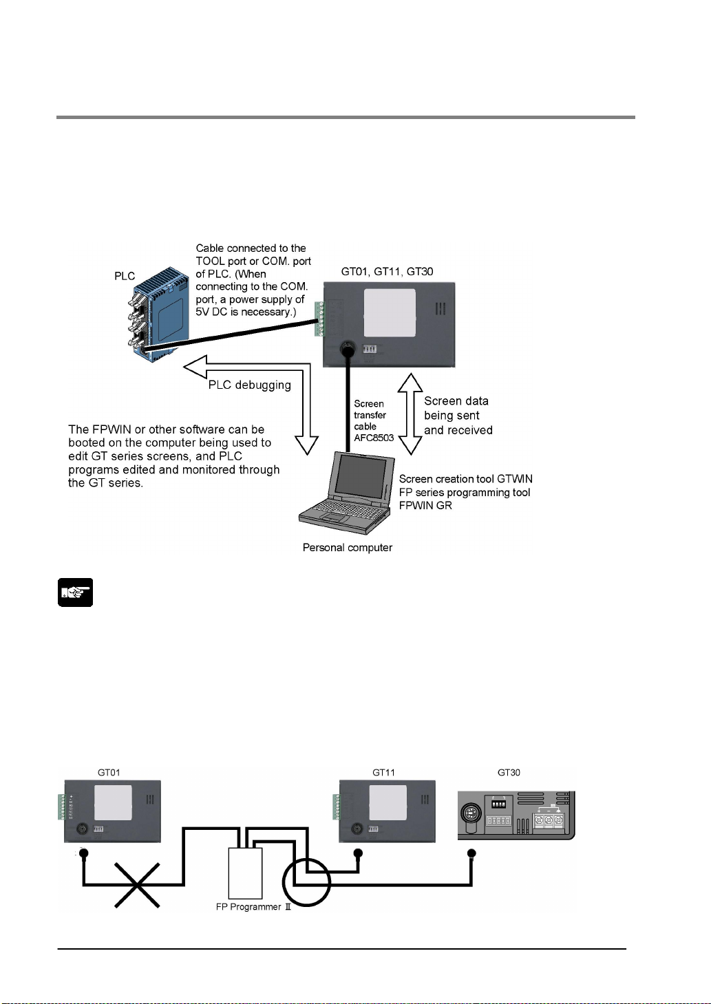
4.1.17 Through Function
With the GT series, communication can be set to take place automatically between the COM. port and
TOOL ports in a “through function”. When the FP series tool software installed in the computer
connected to the GT series as shown below is booted, PLC programs can be edited through the GT
series.
The through function does not require any special settings, and is always in the standby mode.
Note:
• Precautions when using the through function
The system should be set up so that the Timeout period in the FP series software (FPWIN) (A) is larger
than the waiting time for communication retries of the GT COM. port (B), meaningn (A) > (B). If the
system is set up so that A = B or A < B, the through function will not work properly.
• Restrictions on COM. port connections
When connecting the GT01 to the COM. port of a PLC, a separate external 5V DC power supply must
be provided. Be sure to remember this.
• An FP Programmer II cannot be connected to the tool port of the GT01. It can be connected to the
GT11 and GT30.
4-20
Page 81
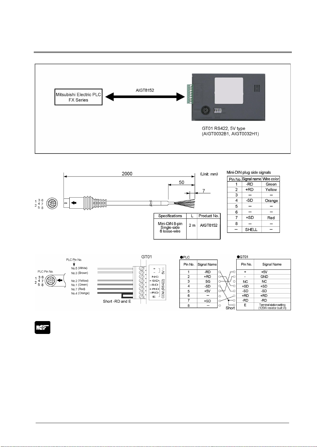
4.1.18 Connecting a PLC by Mitsubishi Electric Corporation
Connecting to the TOOL port of FX series (1) (Direct connection to GT01)
PLC communication cable: Mini-DIN 8-pin loose-wire cable (AIGT8152)
Tool port connection of GT01 and FX Series
Note:
• Keep the cable no longer than 2 m
• GT01 power consumption corresponds to that of Mitsubishi’s F920 (5 V type) display device. When
using, adhere to the conditions of use (number of units that can be expanded on a PLC, etc.) for the
F920 (5 V type).
4-21
Page 82
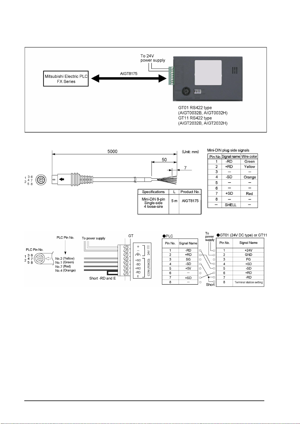
Connecting to the TOOL port of FX series (2)
PLC communication cable: Mini-DIN 8-pin loose-wire cable (AIGT8175)
Tool port connection of GT01 and FX Series
4-22
Page 83
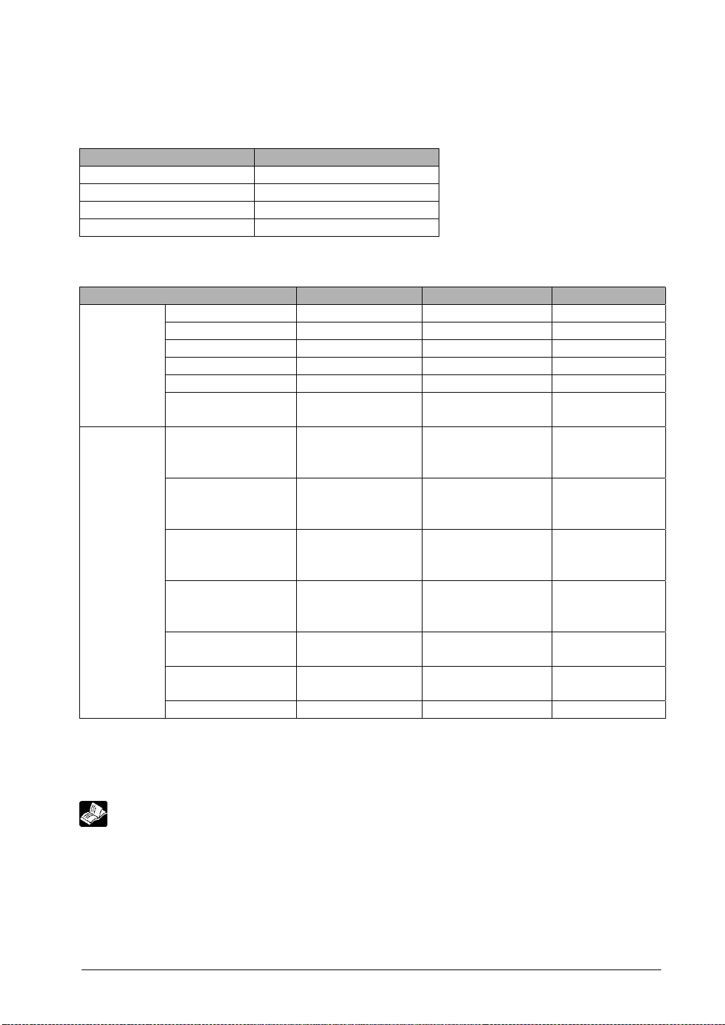
Setting the communication conditions
Setting communication conditions on the GT side
Set the COM. port communication conditions as follows.
Item Value set
Baud rate 9600 bps
Data length 7 bits
Parity check Yes, even
Stop bit 1 bit
Usable devices
Device type FX1N range No. FX2N range No. Remarks
Input relay (X) X0000 to X0337 X0000 to X0337
Output relay (Y) Y0000 to Y0337 Y0000 to Y0337
Internal relay (M) M0000 to M1535 M0000 to M1535
Bit device
State (S) S0000 to S0999 S0000 to S0999
Timer (contact) (TS) TS0000 to TS0255 TS0000 to TS0255
Counter (contact)
(CS)
CS0000 to CS0255 CS0000 to CS0255
Designate the
Input relay (X) X0000 to Y0320 X0000 to X0320
address in
increments of 20.
Designate the
Output relay (Y) Y0000 to Y0320 Y0000 to Y0320
address in
increments of 20.
Designate the
Internal relay (M) M0000 to M1520 M0000 to M1520
Word device
address in
increments of 16
Designate the
State (S) S0000 to S0976 S0000 to S0976
address in
increments of 16.
Timer (current value)
(TN)
Counter (current
value) (CN)
TN0000 to TN0255 TN0000 to TN0255
CN0000 to CN0255 CN0000 to CN0255
Data register (D) D0000 to D0999 D0000 to D0999
Note1) The addresses you can use may differ depending on the model. For details, please see the
manual for the PLC you are using.
Note2) If using an input relay, output relay and auxiliary relay in word units, please set the address in 16
point increments from 000. (X000, X020, X040 …, M000, M016, M032).
Reference: <Chapter 8 Troubleshooting>
4-23
Page 84
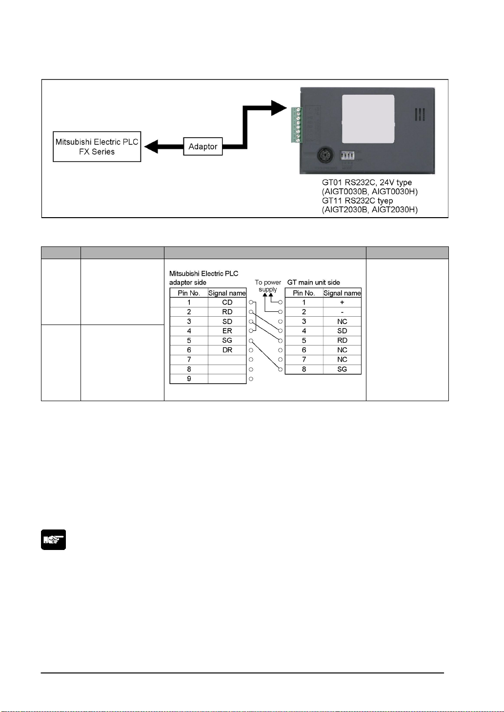
Connecting the FX Series using an adapter (RS232C)
Connection method
CPU Adaptor Wiring diagram GT series
FX1N FX1N-232-BD
GT01, GT11
RS232C type
FX2N FX2N-232-BD
Be aware that communication will not be possible if the above adaptor cannot be connected to the FX
series.
Although No. 6 and 7 of the GT11 is RS/CS, they can be used in the above connection.
Setting the communication conditions for the PLC
“0” should be stored in D8120. (“0” is the default value, so this setting should not need to be entered by
the user.)
Communication condition settings and devices that can be used are the same as those given on
the previous page.
Note:
The RS422 type GT01 and FX series does not support the communication using the adapter for RS422
(or RS485).
4-24
Page 85
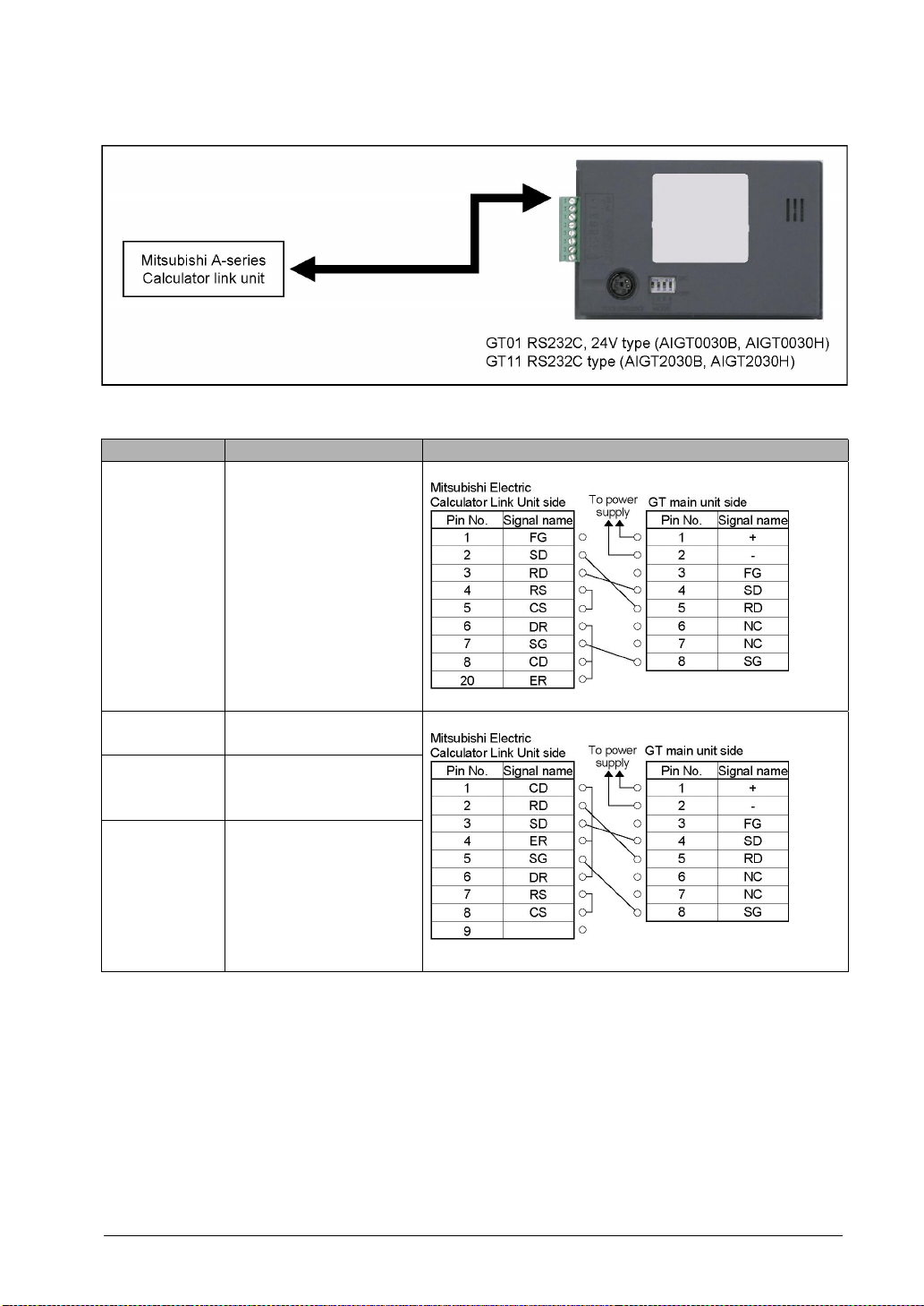
Connecitng the A-series Calculator Link Unit by Mitsubishi Electric Corporation
Connection method
CPU Calculator link unit Wiring diagram
AJ71C24
A1N
A2N
A3N
AF71C24-S3
AJJ71C24-S6
AF71C24-S8
AJ71UC24
(A2N only)
A1S
A1SJ
A2SH
A1SH
A2CCPU24 Link unit on CPU unit
Although No. 6 and 7 of the GT11 is RS/CS, they can be used in the above connection.
A1SJ71C24-R2
A1SJ71UC24-R2
A1SJ71UC24-R2
4-25
Page 86
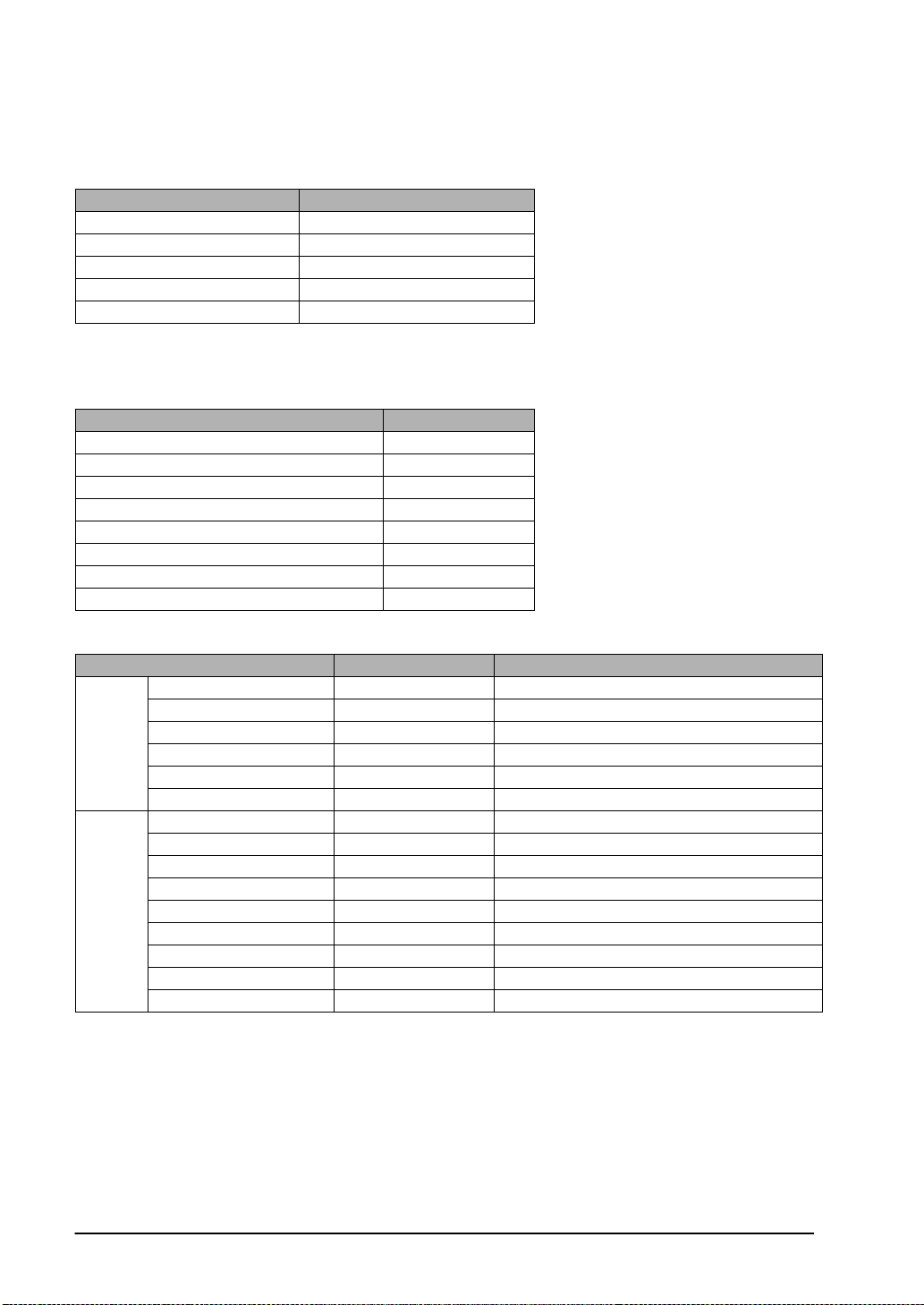
Setting the communication conditions
Setting communication conditions on the GT side
Set the COM. port communication conditions as follows.
Item Value set
PLC unit 0
Baud rate 19200 bps
Data length 7 bits
Parity check Even
Stop bit 1 bit
Setting communication conditions on the PLC side
Set the communication conditions as follows. Some items cannot be set depending on the used model.
There is no need to set the items that are not available.
Item Value set
Unit No. 0
Baud rate 19200 bps
Data length 7 bits
Parity check Even
Stop bit 1 bit
Checksum Available
Interface RS232C
Dedicated protocol control procedure Format 4
Usable devices
Device type FX1N range No. Remarks
Input relay X0000 to X07FF
Output relay Y0000 to Y07FF
Bit
device
Internal relay M0000 to M2047
State B0000 to B03FF
Timer (contact) TS0000 to TS0255
Counter (contact) CS0000 to CS0255
Input relay X0000 to X07F0 Designate the address of first digit with 0.
Output relay Y0000 to Y07F0 Designate the address of first digit with 0.
Internal relay M0000 to M2032 Designate the address in increments of 16
Word
device
Link relay B0000 to B03F0 Designate the address of first digit with 0.
Timer (current value) TN0000 to TN0255
Counter (current value) CN0000 to CN0255
Data register D0000 to D1023
Link register W0000 to W03FF
File register R0000 to R8191
4-26
Page 87
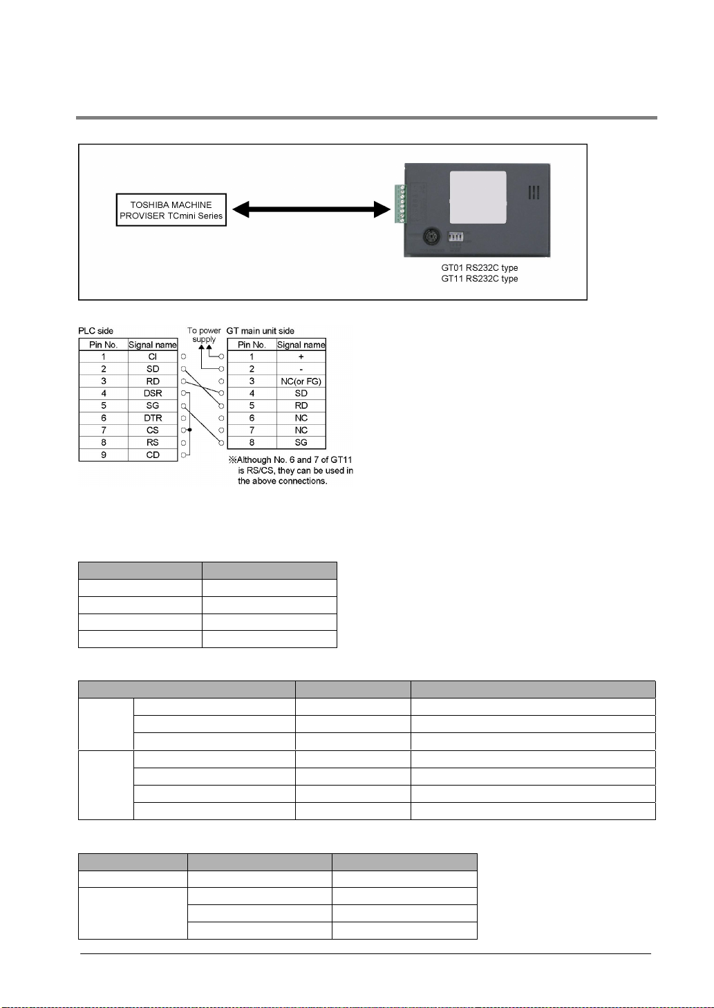
4.1.19 Connecitng the PROVISER Tcmini Series by Toshiba Machine Co., Ltd.
Toshiba Machine PROVISER TCmini Series
Connection method
Setting the communication conditions
Recommended GT and PLC communication settings are as follows.
GT communication settings (Set with the GTWIN configuration settings)
Item Value set
Baud rate 19200 bps
Data length 8 bits
Parity check None
Stop bit 1 bit
Usable devices
Device type No. Remarks
Bit
device
Word
device
Each PLC device is coded as follows on the GTWIN. When inputting a device, use these codes.
Bit device R120 R120
Input X000 to XF7F
Output Y000 to YF7F
Internal relay R000 to R77F
Input X00W to XF7W
Output Y00W to YF7W
Internal relay R00W to R77W
General purpose register D000 to DF7F
Display of PLC Display of GTWIN
R12W RW12
X12W XW12Word device
Y12W YW12
4-27
Page 88
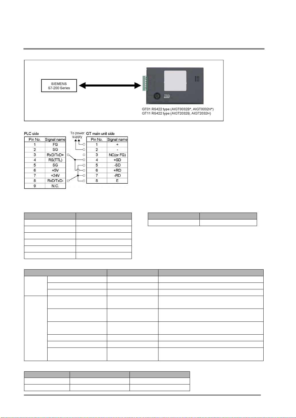
4.1.20 Connecitng the S7-200 Series by Siemens K. K.
SIEMENS S7-200 Series
Connection method
Setting the communication conditions
Recommended GT and PLC communication settings are as follows.
GT communication settings Communication settings on the PLC side
Item Value set Item Value set
GT unit No. 01 PLC unit No. 02
PLC unit No. 02
Baud rate 9600 bps
Data length 8 bits
Parity check Even
Stop bit 1 bit
Usable devices
Device type FX1N range No. Remarks
Bit
device
Word
device
Each PLC device is coded as follows on the GTWIN. When inputting a device, use these codes.
Bit device Q3.2 Q3-2
Word device VW100 VW100
4-28
Input I00 to I77
Output Q00 to Q77
Bit memory M00 to M317
Input IW0 to IW6
Output QW0 to QW6
Bit memory MW0 to MW30
Timer (current value) T0 to T255
Counter (current value) C0 to C255
Integer VW000 to VW518
Display of PLC Display of GTWIN
The number of the addresses which can be
set is even.
The number of the addresses which can be
set is even.
The number of the addresses which can be
set is even.
The number of the addresses which can be
set is even.
Page 89
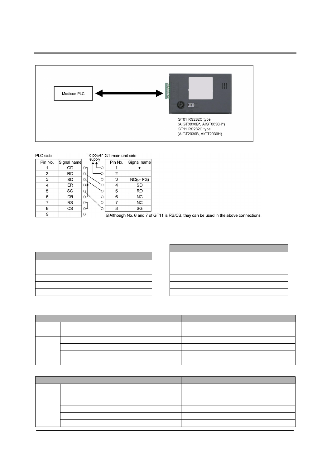
4.1.21 Connecitng a PLC by Modicon
Modicon PLC
Connection method
Setting the communication conditions
Recommended GT and PLC communication settings are as follows.
Communication settings on the PLC sideGT communication settings
(Set with the GTWIN configuration settings.)
Item Value set
PLC unit No. 1 Mode RTU mode
Baud rate 19200 bps Baud rate 19200 bps
Data length 8 bits Data length 8
Parity check Even Stop bit 1
Stop bit 1 bit Parity Even
Note) It cannot be used without parity.
Slave address 1
Item Value set
Usable devices
Device type No. Remarks
Bit
device
Word
device
Addresses will be as follows when “Modbus” (RTU mode | modicon PLC) is selected as the PLC type.
Bit
device
Word
device
Input relay 100000 to 165535
Coil 000000 to 065535
Input relay 100000 to 165535 Designate the address in multiples of 16.
Coil 000000 to 065535 Designate the address in multiples of 16.
Input register 300000 to 365535
Hold register 400000 to 465535
Device type No. Remarks
Input relay 100001 to 165536
Coil 000001 to 065536
Input relay 100001 to 165536 Designate the address in multiples of 16.
Coil 000001 to 065536 Designate the address in multiples of 16.
Input register 300001 to 365536
Hold register 400001 to 465536
4-29
Page 90
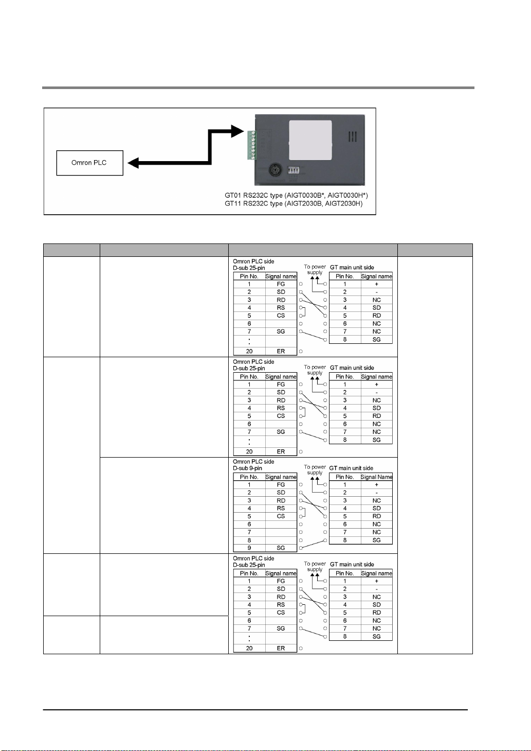
4.1.22 Connecting PLCs by Omron Corporation
SYSMAC C Series, αααα Series, CV Series and CS1 Series
Connection method
SYSMAC C Series (Using Link I/F)
CPU Link I/F Wiring diagram GT series
C200H
C200HS
C500
C500F
C1000H
C2000
C2000H
C200H-LK201
C120-LK201-V1
C200H-LK201
C120-LK201-V1
Note1)
Note2)
Note1)
Note2)
Link I/F on the CPU unit
C120-LK201-V1
C500-LK201-V1
C500-LK203
Note2)
Note1)
Note1)
GT01, GT11
RS232C type
Note3)
C1000HF C500-LK203
Note1)
Note1) Base mounting type
Note2) CPU mounting type
Note3) Connecting to the RS232C port
Note4) Although No. 6 and 7 of the GT11 is RS/CS, they can be used in the above connection.
4-30
Page 91
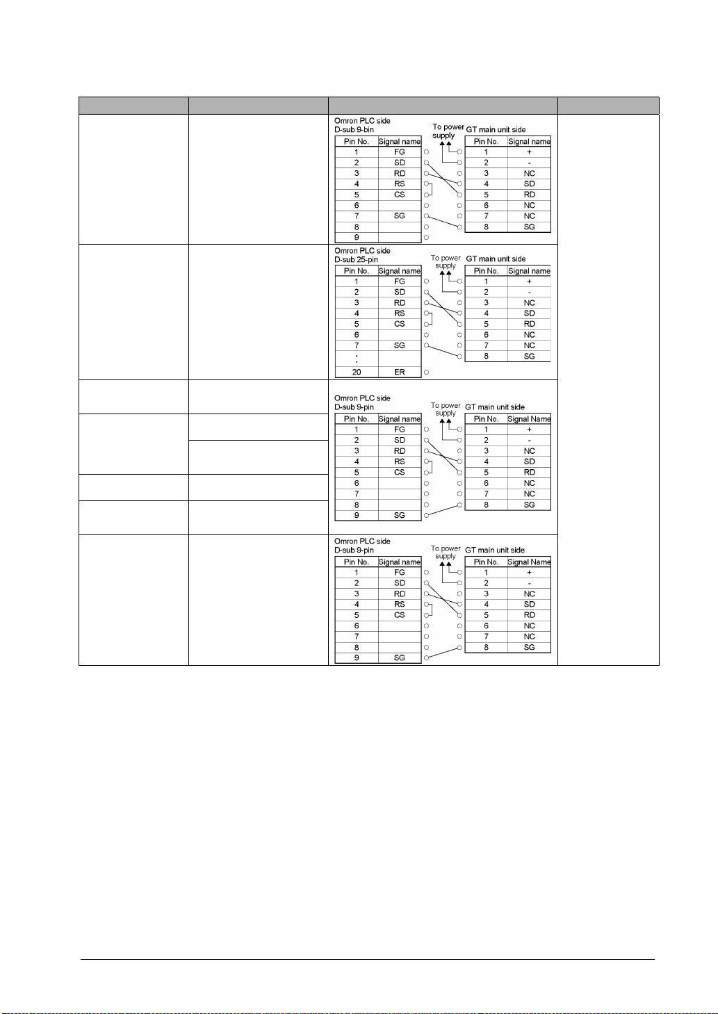
CPU Link I/F Wiring diagram GT series
C20H
C28H
C40H
C120
C120F
CQM1-CPU42
SRM1-C02
CPM2A
Link I/F on the CPU
Note3)
unit
C120-LK201-V1
RS232C port on the
CPU unit
CPM1-C1F01
RS232C port on the
CPU unit
CPM1-20CDR-A CPM1-C1F01
CQM1H-CPU21
RS232C port on the
CPU unit
Note2)
GT01, GT11
RS232C type
CPM2C
Note4)
Peripheral port on the
CPU unit
Note2) CPU mounting type
Note3) Connecting to the RS232C port
Note4) An Omron CS1W-C118 (D-sub 9-pin) or CPM2C-CN111 cable is required.
Note5) Although No. 6 and 7 of the GT11 is RS/CS, they can be used in the above connection.
4-31
Page 92
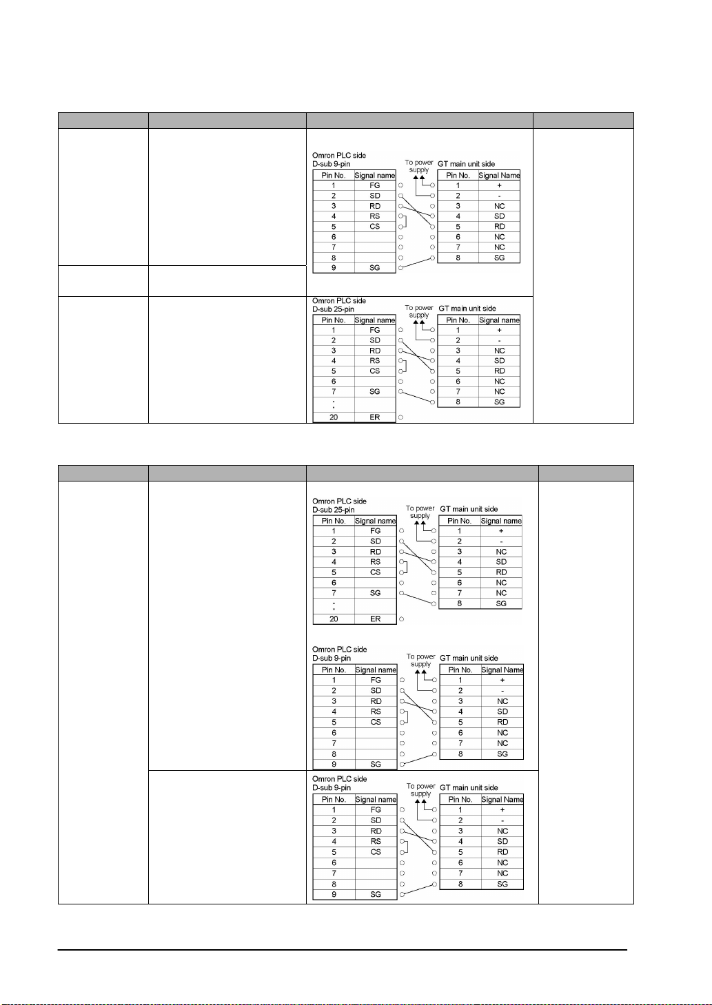
SYSMAC αααα Series (Using Link I/F)
CPU Link I/F Wiring diagram GT series
C200HX CPU85-Z
CPU64
CPU44
C200HE-
C200HW-COM06
CPU42
C200HG CPU63
CPU43
C200HECPU42-Z
RS232C port on the CPU
unit
GT01, GT11
RS232C type
C200HXCPU64-Z
C200-LK201-V1
Note) Although No. 6 and 7 of the GT11 is RS/CS, they can be used in the above connection.
SYSMAC CV Series (Using Link I/F)
CPU Link I/F Wiring diagram GT series
Connecting to the communication port 1
CV500-LK201
Connecting to the communication port 2
CV500
CV1000
CVM1
GT01, GT11
RS232C type
Link I/F on the CPU unit
Note1)
Note1) Connect to the HOSTLINK port.
Note2) Although No. 6 and 7 of the GT11 is RS/CS, they can be used in the above connection.
4-32
Page 93
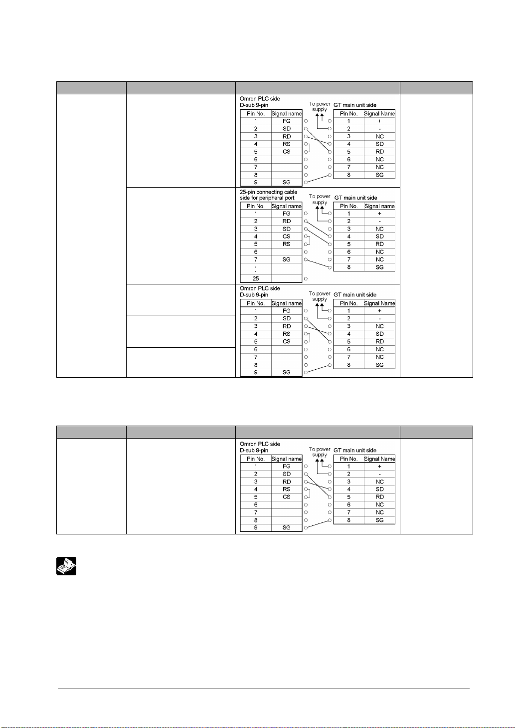
SYSMAC CS1 Series (In case of 1:1)
CPU Link I/F Wiring diagram GT series
RS232C port on the
CPU unit
CS1H-CPU67
CS1H-CPU66
CS1H-CPU65
CS1H-CPU64
CS1H-CPU63
CS1G-CPU45
Peripheral port on the
CPU unit
Note1)
CS1G-CPU44
CS1G-CPU43
CS1G-CPU42
CS1W-SCU21
CS1W-SCB21
CS1W-SCB41
GT01, GT11
RS232C type
Note1) Connection to the peripheral port requires a CS1W-CN225 or CS1W-CN625 cable.
Note2) Although No. 6 and 7 of the GT11 is RS/CS, they can be used in the above connection.
SYSMAC CJ1 Series
CPU Link I/F Wiring diagram GT series
CJ1
CJ1M
RS232C port on the
CPU unit
GT01, GT11
RS232C type
Note) Although No. 6 and 7 of the GT11 is RS/CS, they can be used in the above connection.
Reference: <Chapter 8 Troubleshooting>
4-33
Page 94
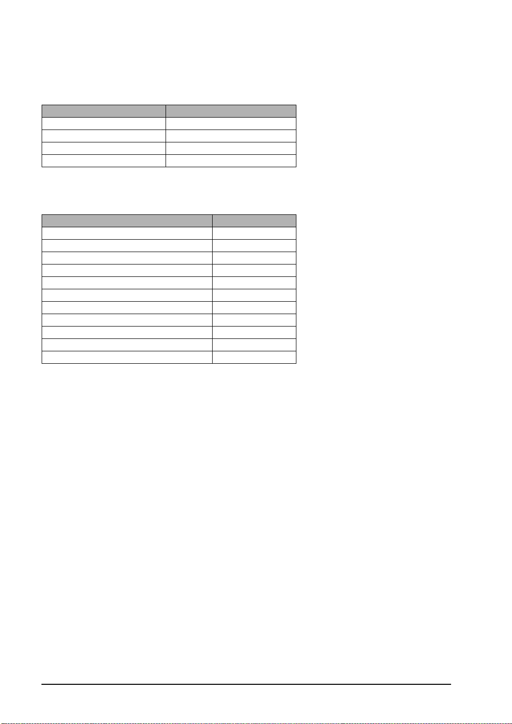
Setting the communication conditions
Setting communication conditions on the GT side
Set the COM. port communication conditions as follows.
Item Value set
Baud rate 19200 bps
Data length 7 bits
Parity check Yes, Even
Stop bit 1 bit
Setting communication conditions on the PLC side
Set the communication conditions as follows. Some items cannot be set depending on the used model.
There is no need to set the items that are not available.
Item Value set
PLC mode Monitor mode
Mode designation High link
Procedure 1:N
Baud rate 19200 bps
Data length 7 bits
Parity check Yes, Even
Stop bit 1 bit
Unit No. No. 0
CTS designation Always ON
5 V supply None
Communication system RS232C
Note) Be sure to use the PLC in monitor mode.
4-34
Page 95
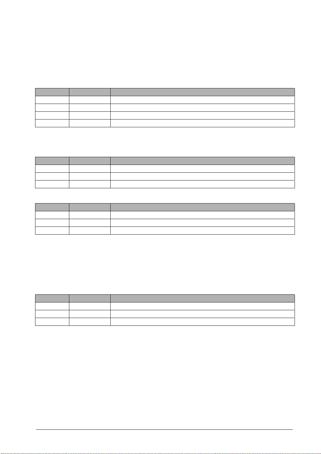
For almost all models the PLC communication setting method is as follows. However, differences
may arise depending on the model. For details, please consult the manual for the PLC you will
use when making the settings.
To communicate using the RS232C port of the CPU unit
Set the system area as follows.
Address Value set Setting
DM6600 0201 (HEX) Setting of PLC main unit mode (monitor mode)
DM6645 0001 (HEX) Mode setting of RS232C port (high link)
DM6646 0004 (HEX) Setting of communication conditions (19200 bps, 7 bits, even, 1 bit)
DM6648 0000 (HEX) Setting of device number (Device No. 0)
To communicate using the communication port
Set the system area as follows.
To communicate with port A
Address Value set Setting
DM6600 0201 (HEX) Setting of PLC main unit mode (monitor mode)
DM6550 0001 (HEX) Mode setting of RS232C port (high link)
DM6551 0004 (HEX) Setting of communication conditions (19200 bps, 7 bits, even, 1 bit)
To communicate with port B
Address Value set Setting
DM6600 0201 (HEX) Setting of PLC main unit mode (monitor mode)
DM6555 0001 (HEX) Mode setting of RS232C port (high link)
DM6556 0004 (HEX) Setting of communication conditions (19200 bps, 7 bits, even, 1 bit)
To communicate using the high link I/F unit
Make sure set the CPU mode to monitor mode.
Use the DIP switch or rotary switch on the link I/F unit to make settings such as the baud rate.
For details please refer to the manual for the unit your are using.
To communicate using the peripheral port
Set the system area as follows.
Address Value set Setting
DM6600 0201 (HEX) Setting of PLC main unit mode (monitor mode)
DM6550 0001 (HEX) Mode setting of RS232C port (high link)
DM6551 0004 (HEX) Setting of communication conditions (19200 bps, 7 bits, even, 1 bit)
4-35
Page 96
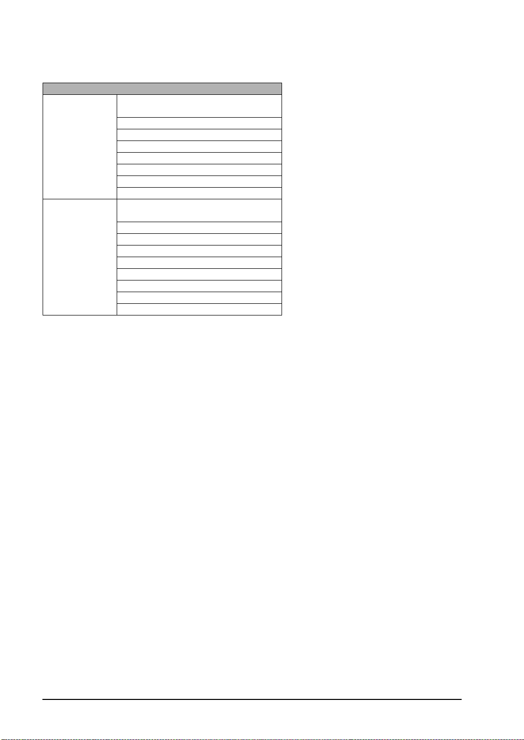
Usable devices
Device type
I/O relay
Internal auxiliary relay
Analog setting storage area
Special auxiliary relay
Bit device
Word device
Note1) The range of usable addresses differs depending on the model. For details, please consult the
manual for the PLC you will use.
Note2) Data area 253 to 255CH cannot be written to.
Note3) The data link relay (LR), hold relay (HR), timer (TIM) and counter (CNT) of the J1 series cannot
be used.
Data link relay (LR)
Auxiliary memory relay (AR)
Hold relay (HR)
Timer (contact) (TIM)
Counter (contact) (CNT)
I/O relay
Internal auxiliary relay
Analog setting storage area
Special auxiliary relay
Data link relay (LR)
Auxiliary memory relay (AR)
Hold relay (HR)
Timer (current value) (TIM)
Counter (current value) (CNT)
Data memory (DM/D)
4-36
Page 97
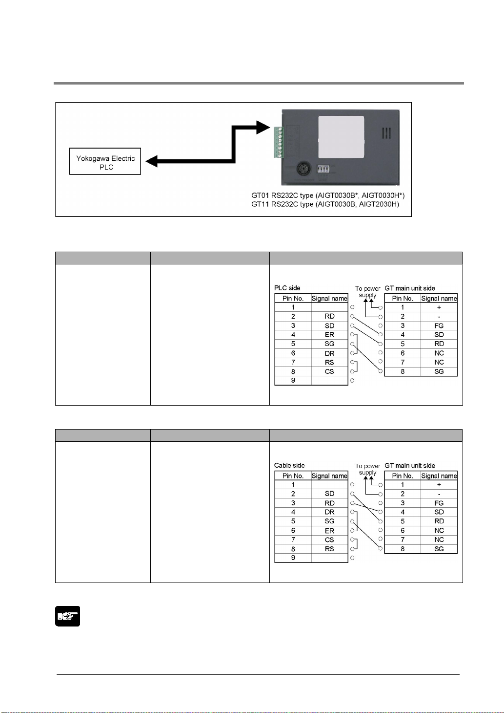
4.1.23 Connecting a PLC by Yokogawa Electric Corporation
FA-M3 Series
Connection method
Using PC link module
CPU PC link module Wiring diagram
F3SP21-0N
F3SP25-2N
F3SP28-3N
F3SP28-3S
F3SP35-5N
F3SP38-6N
F3SP38-6S
F3SP53-4H
F3SP53-4S
F3SP58-6H
F3SP58-6S
F3SP59-7S
F3LC11-1N
F3LC11-1F
F3LC12-1F
Direct connection to CPU
CPU PC link module Wiring diagram
F3SP21-0N
F3SP25-2N
F3SP28-3N
F3SP28-3S
F3SP35-5N
F3SP38-6N
F3SP38-6S
F3SP53-4H
F3SP53-4S
F3SP58-6H
F3SP58-6S
F3SP59-7S
Note) Although No. 6 and 7 of the GT11 is RS/CS, they can be used in the above connection.
Note:
• When connecting to the CPU directly, make the setting to “Using CPU PC link function” using a
program-development tool, etc.
KM11-2T
4-37
Page 98
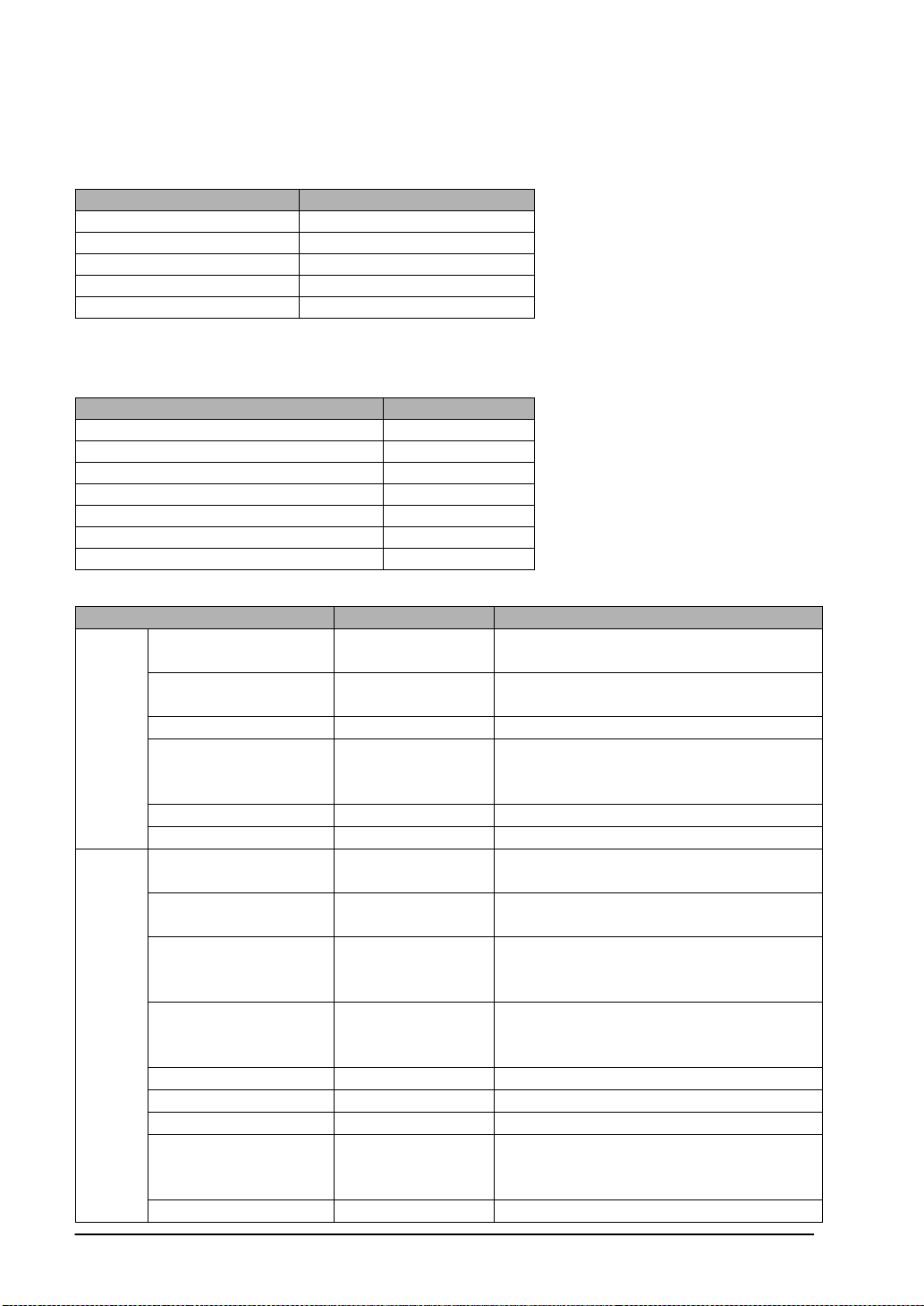
Setting the communication conditions
Setting communication conditions on the GT side
Set the COM. port communication conditions as follows.
Item Value set
PLC unit No. 1
Baud rate 19200 bps
Data bit 8
Parity check None
Stop bit 1 bit
Setting communication conditions on the PLC side
Set the communication conditions as follows. Some items cannot be set depending on the used model.
There is no need to set the items that are not available.
Item Value set
Unit No. 1
Baud rate 19200 bps
Data bit 8
Parity check None
Stop bit 1 bit
Checksum None
Termination character designation Available
Usable devices
Device type No. Remarks
Designate the slot No. (1 digit) + unit No. (2
digits) + terminal No. (2 digits).
Designate the slot No. (1 digit) + unit No. (2
digits) + terminal No. (2 digits).
Designate the system No. (1 digit) + link
relya No. (4 digits). The system No. 0 is
Bit
device
Input relay X00201 to X71664
Output relay Y00201 to Y71664
Internal relay I00001 to I16000
Link relay L00001 to L08192
only available.
Timer T0001 to T3072
Counter C0001 to C3072
Input relay X00201 to X71649
Output relay Y00201 to Y71649
Designate the last 2 digits of the address to
be 17, 33, 49.
Designate the last 2 digits of the address to
be 17, 33, 49.
Designate the address in increments of the
Internal relay I00001 to I15985
values of which reminder is 1 when being
devided by 16.
Word
device
Link relay L00001 to L08177
Designate the address in increments of the
values of which reminder is 1 when the last
4 digits are devided by 16.
Timer (current value) TP0001 to TP3072
Counter (current value) CP0001 to CP3072
Data register D00001 to D65535
Designate the system No. (1 digit) + link
Link register W00001 to W08192
register No. (4 digits). The system No. 0 is
only available.
File register B00001 to B99999
4-38
Page 99
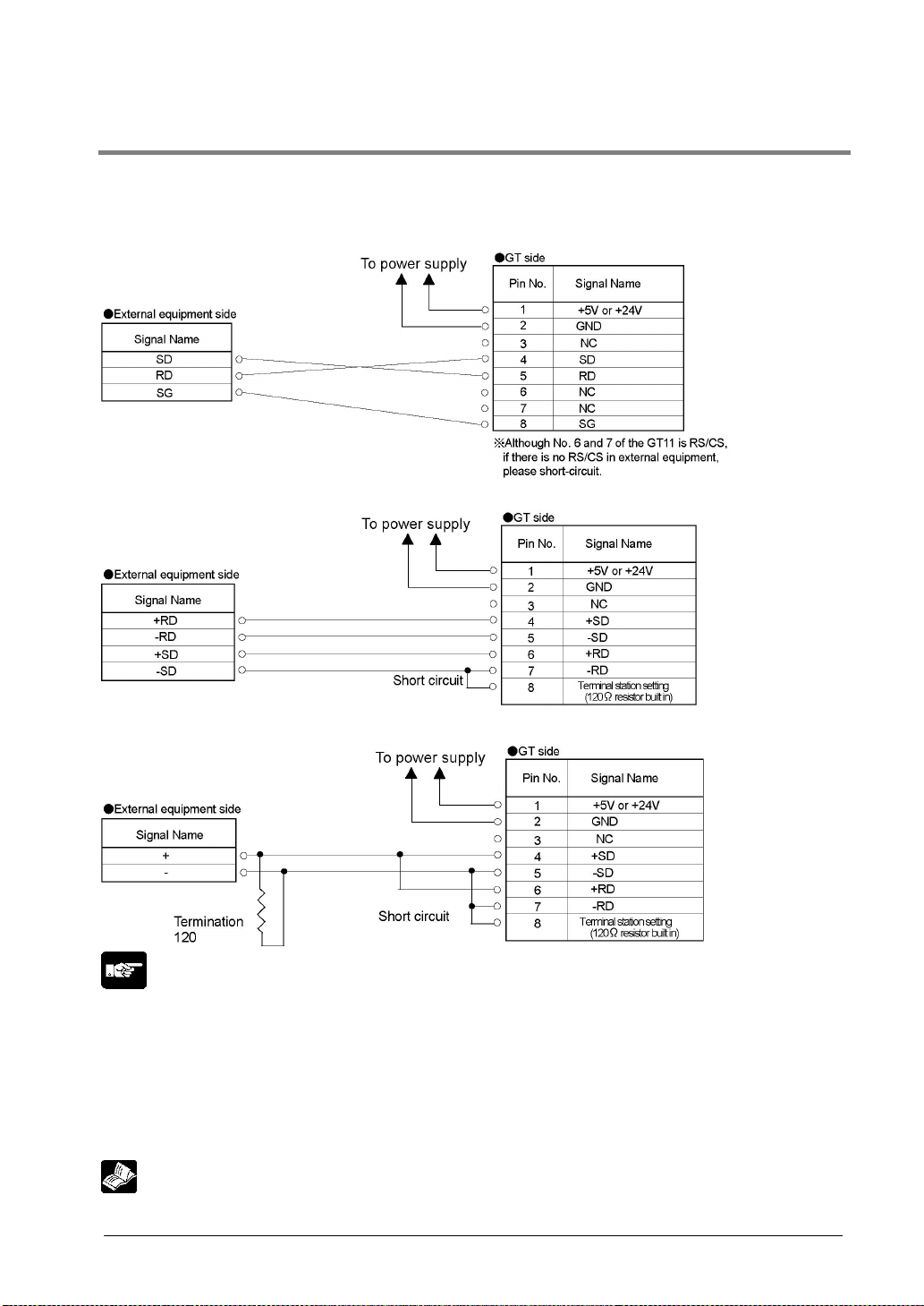
4.1.24 Connecting a Sereial Device
Devices other than PLCs can be connected by using the general-purpose serial communication mode of
the GT. Refer to the following regarding PLCs that are not included in this manual.
Connecting to the RS232C
Connecting to the RS422
Connecting to the RS485 (1:1 connection) (AIGT0032**)
Note:
• If noise is a problem, use a shielded cable and employ countermeasures such as installing a ferrite
core if necessary. Also take measures so that the shielding doesn’t peel off and noise such as static
electricity does not interfere.
• When connecting to a device other than our FP Series, the number of units, transmission distance and
baud rate my differ depending on the device connected. Verify with the device being used.
• The maximum cable length for RS232C type is 15 m, also RS422 (5 V) type is 30 m.
• The maximum transmission distance is 500 m for the 24 V RS422 type.
Reference: <GT Series General-purpose Serial Communication Manual ARCT1F356>
4-39
Page 100
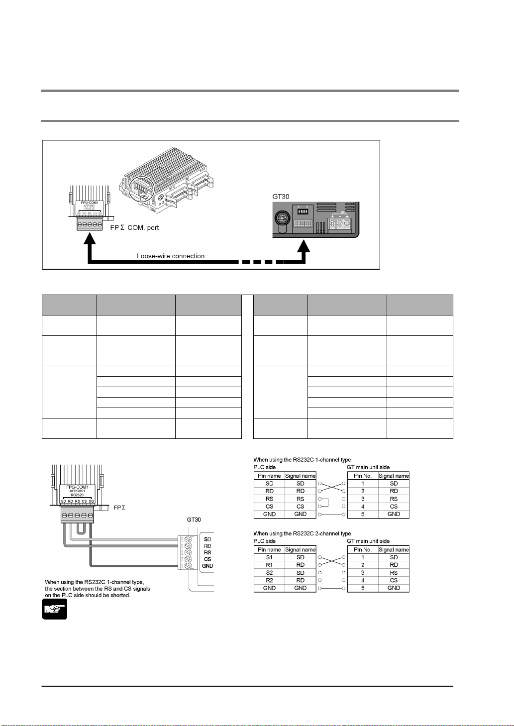
4.2 Connecting GT30 with PLC
4.2.1 Connecting to the FPΣΣΣΣ
Connecting to the COM. port
FPΣΣΣΣ communication format settings
When using COM. port 1 When using COM. port 2
System
register No.
410
412
413
415
Item Value set
COM. port 1
unit No.
COM. port 1
communication
mode
Data length 8 bits Data length 8 bits
Parity c h ec k Yes, Odd Parit y c heck Yes, Odd
Stop bits 1 bit Stop bits 1 bit
End code CR (Fixed) End code CR (Fixed)
Start code No STX (Fixed)
COM. port 1
Baud rate setting
1411
Computer link
No modem
connection
9600 bps 415
System
register No.
412
414
Item Value set
COM. port 2
unit No.
COM. port 2
communication
mode
Start code No STX (Fixed)
COM. port 2
Baud rate setting
1
Computer link
No modem
connection
9600 bps
Connecting to the FPΣΣΣΣ COM. port
Note:
• Because loose wiring is used for connection to the FPΣ COM. port, no dedicated cable is available.
The cable should be provided by the custom er. When purchasing a cable, the following precautions
should be observed.
• Shielded wire with a size of AGW#28 to 16 (conductor cross-section surface area: 0.08 mm
2
) should be used for connections.
mm
2
to 1.25
4-40
 Loading...