

NAiS EBL512 Operating Instructions Manual
Operating Instructions
MEW00442
Revision -
Fire Alarm System EBL512
Author: Jan Pettersson Date: 2003-09-09 Rev. date:
Checked by: Mikael Östergren S-class: Public Rev. by:
Approved by: Rutger Pålsson Number of pages: 111
L:\Product Documentation\Manuals\Doc\MEW00442.doc
V1.44.x

This page has deliberately been left blank.

Matsushita Electric Works Fire & Security Technology AB
MEW00442 Rev: - Operating Instructions EBL512, V1.44.x
Table of contents
1 Introduction________________________________ 5
2 Definitions / Explanations ____________________ 6
2.1 MFSTech_________________________________________ 6
2.2 Alarm points ______________________________________ 6
2.2.1 Smoke detector _______________________________ 6
2.2.2 Sensor ______________________________________ 6
2.2.3 Analog detector _______________________________ 6
2.2.4 (Analog) Sensor Base (ASB)_____________________ 6
2.2.5 Conventional detector __________________________ 6
2.2.6 Conventional Detector Base (CDB) _______________ 6
2.2.7 Addressable Detector Base (ADB) ________________ 6
2.2.8 Addressable __________________________________ 7
2.2.9 Old detector __________________________________ 7
2.2.10 External line / Conventional zone line _____________ 7
2.2.11 ADB input / Addressable zone interface ____________ 7
2.3 Output unit _______________________________________ 7
2.4 Output / Control output ______________________________ 7
2.5 Short circuit isolator ________________________________ 7
2.6 Display unit _______________________________________ 7
2.7 COM loop ________________________________________ 7
2.8 BS4 loop _________________________________________ 7
2.9 Control Unit (C.U.) / C.I.E.___________________________ 8
2.10 Fire Brigade Panel (FBP) ____________________________ 8
2.11 Control panel (CP) _________________________________ 8
2.12 System___________________________________________ 8
2.13 Network / TLON® / LonWorks® / Echelon / Node / TLON
Conn. board / Gateway / Channel / Router / Repeater ____________ 8
2.14 LED_____________________________________________ 9
2.15 External Indicator (LED) ____________________________ 9
2.16 Display / LCD _____________________________________ 9
2.17 Door open / Key switch______________________________ 9
2.18 SSD / Site Specific Data _____________________________ 9
2.19 SW / Software / System program ______________________ 9
3 Overview _________________________________ 10
3.1 The EBL512 system _______________________________ 10
3.1.1 Expansion boards ____________________________ 10
3.1.2 Printer _____________________________________ 10
3.2 SW versions _____________________________________ 10
3.3 Documents_______________________________________ 11
3.4 Applications _____________________________________ 11
3.5 PC SW__________________________________________ 11
4 Control Unit ______________________________ 12
1

Matsushita Electric Works Fire & Security Technology AB
MEW00442 Rev: - Operating Instructions EBL512, V1.44.x
5 LED indicators and push buttons _____________ 14
6 Access levels_______________________________ 17
6.1 Access level 1 ____________________________________ 17
6.2 Access level 2 ____________________________________ 18
6.3 Access level 3 ____________________________________ 19
6.4 Access level 4 ____________________________________ 20
6.5 Access level 5 ____________________________________ 20
7 Normal operation __________________________ 21
8 Push button "Silence" ______________________ 22
8.1 Silence before a fire alarm __________________________ 22
8.2 Silence during a fire alarm __________________________ 22
9 Alarm device on / Alarm device off____________ 23
10 Controls ON / Controls OFF _________________ 24
11 Door open (Key switch) _____________________ 25
11.1 LED "Key switch"_________________________________ 25
11.2 Disable outputs for routing equipment (Fire brigade tx and
Fault tx) _______________________________________________ 25
12 Technical number / Presentation number ______ 26
12.1 Technical number for COM loop units _________________ 26
12.2 Technical number for BS4 loop units __________________ 27
12.3 Presentation number _______________________________ 28
13 Alarm types _______________________________ 29
13.1 Pre-alarm________________________________________ 29
13.2 Fire alarm _______________________________________ 30
13.2.1 Alert annunciation ____________________________ 31
13.2.2 2-zone / address dependence ____________________ 31
13.3 Heavy smoke alarm________________________________ 31
14 Key cabinet _______________________________ 32
14.1 Key cabinet alarm _________________________________ 32
14.2 Key cabinet opened in conjunction with a fire alarm ______ 32
14.2.1 Restoring the key after a fire alarm _______________ 32
15 Alarm reset _______________________________ 33
15.1 Pre-alarm reset ___________________________________ 33
15.2 Fire alarm reset ___________________________________ 33
15.3 Heavy smoke alarm reset ___________________________ 33
15.4 Key cabinet alarm reset_____________________________ 34
15.5 Zone/Detector not reset _____________________________ 34
16 Fault _____________________________________ 35
16.1 Fault messages ___________________________________ 35
16.2 Fault acknowledge ________________________________ 47
17 Commissioning an installation _______________ 48
17.1 Single Control Unit ________________________________ 48
2

Matsushita Electric Works Fire & Security Technology AB
MEW00442 Rev: - Operating Instructions EBL512, V1.44.x
17.2 Control Units in a TLON network ____________________ 48
17.2.1 TLON network programming (configuration) ______ 49
18 Programming (SSD download) _______________ 50
18.1 Single Control Unit ________________________________ 50
18.2 Control Units in a TLON network ____________________ 50
18.3 User definable text messages download ________________ 51
18.3.1 Download in Control unit ______________________ 51
18.3.2 Download in Display unit ______________________ 51
19 New system program (SW) version download ___ 52
19.1 Control Units in a TLON network ____________________ 52
20 EBL512 settings download___________________ 53
20.1 Control Units in a TLON network ____________________ 54
21 Reset / Restart _____________________________ 55
22 Access ____________________________________ 57
23 Perform monthly test (H1)___________________ 58
24 Disable or re-enable (H2) ____________________ 60
24.1 Disable zone (H2/B1) ______________________________ 61
24.2 Disable zone / address (H2/B2)_______________________ 62
24.3 Disable control output (H2/B3)_______________________ 63
24.4 Re-enable zone (H2/B4) ____________________________ 64
24.5 Re-enable zone / address (H2/B5)_____________________ 65
24.6 Re-enable control output (H2/B6)_____________________ 66
24.7 Re-enable non-reset zone / address (H2/B7)_____________ 67
24.8 Control on / Control off (H2/B8) _____________________ 68
24.9 Alarm device on / Alarm device off (H2/B9) ____________ 69
25 Set calendar and clock (H3) __________________ 70
26 Present system status on display and printer (H4) 71
26.1 Disablement (H4/U1) ______________________________ 71
26.2 Disablement by time channel (H4/U2) _________________ 72
26.3 Show open doors (H4/U3) __________________________ 73
26.4 Activated 2-zone/address dependent (H4/U4) ___________ 74
26.5 Show sensors week average values (H4/U5) ____________ 75
26.5.1 Reset of a sensor week average value _____________ 75
26.6 Show sensors momentary values (H4/U6) ______________ 76
26.7 Sensors activating SERVICE signal (H4/U7)____________ 77
26.8 Show event log (H4/U8) ____________________________ 78
26.9 Show configuration (H4/U9)_________________________ 79
27 Programming (H5) _________________________ 80
27.1 Access code for programming (H5) ___________________ 81
27.2 Calibration of monitored outputs (H5/A1) ______________ 82
27.3 Sensitive fault detection mode (H5/A2) ________________ 83
27.4 Direction for communication on COM-loop (H5/A3) _____ 84
27.5 Show information about site specific data (H5/A4) _______ 85
3

Matsushita Electric Works Fire & Security Technology AB
MEW00442 Rev: - Operating Instructions EBL512, V1.44.x
27.6 Display current consumption in unit (H5/A5)____________ 86
27.7 Display current consumption COM-/BS4-loop (H5/A6) ___ 87
27.8 Display statistics for COM-loop (H5/A7)_______________ 88
27.9 Select unit on COM-loop to use for triggering (H5/A8)____ 89
27.10 Change access code for PC-communication (H5/A9) ___ 90
27.11 Change access code for programming (H5/A10)_______ 91
28 Acknowledge FAULTS (H6) _________________ 92
29 Perform ZONE TEST (test mode) (H7) ________ 93
30 Maintenance (H8) __________________________ 95
30.1 Access code for maintenance ________________________ 95
30.2 Disable or re-enable outputs for routing equipment (H8/S1) 96
30.3 Disconnect COM-loop (H8/S2) ______________________ 97
30.4 Re-connect Loop (H8/S3) ___________________________ 98
30.5 Acknowledge SERVICE signal (H8/S4)________________ 99
30.6 Safe shut down of control unit (H8/S5) _______________ 100
30.7 Activate address in alarm mode (H8/S6) ______________ 101
30.8 Synchronize the control units (H8/S7) ________________ 102
30.9 Change access code for maintenance (H8/S8) __________ 103
31 Change access code for daily duties (H9) ______ 104
32 Annual control ___________________________ 105
33 Changing paper in the printer_______________ 106
34 Battery maintenance_______________________ 107
35 How to avoid unnecessary (nuisance) fire alarms 108
36 Information regarding radioactive radiation source110
37 Revision history___________________________ 111
4

Matsushita Electric Works Fire & Security Technology AB
MEW00442 Rev: - Operating Instructions EBL512, V1.44.x
1 Introduction
EBL512 Operating Instructions, is a document intended to be used by
the end user and the fire brigade personnel as well as service /
commissioning engineer.
Due to continual development and improvement, different SW
versions are to be found. This document is valid for SW version
1.44.x.
Since the EBL512 control unit (c.i.e.) is produced for many countries
the look, the texts, the functions, etc. may vary.
Products
Consists of one or more parts (HW) according to a Product Parts
List. A product has:
• a type number (e.g. 1548)
• an article number, often = the type no. and sometimes is a
country code added (e.g. 1548SE)
• a product name (e.g. EBL512 control unit, 128 addresses,
without printer)
HW
A HW (e.g. a printed circuit board) has:
• a type number (e.g. 1556)
• an article number, often = the type no. and sometimes is a
country code added (e.g. 1556SE)
• a product name (e.g. Main Board 128 addr.)
• a p.c.b. number (e.g. 9261-3A) and could have a configuration
(e.g. CFG: 1), a revision (e.g. REV: 2)
• sometimes a SW
SW
A SW has:
• a version number (e.g. V1.44.1)
• sometimes additional information
functions / facilities), Language, Number of addresses, etc.
, such as Convention (different
5

Matsushita Electric Works Fire & Security Technology AB
MEW00442 Rev: - Operating Instructions EBL512, V1.44.x
2 Definitions / Explanations
Definitions / explanations / abbreviations / etc. frequently used or not
explained elsewhere in the document.
2.1 MFSTech
Matsushita Electric Works Fire & Security Technology AB
2.2 Alarm points
Units, which can generate fire alarm (in the control unit), i.e. a sensor,
a conventional detector, a manual call point, etc.
2.2.1 Smoke detector
Two types of analog and conventional smoke detectors are available:
photo electric (optical) and ionization.
2.2.2 Sensor
Sensor = Analog detector
2.2.3 Analog detector
Contains an A/D-converter. The Control Unit pick up the digital
values ("sensor values") for each detector individually. All
evaluations and "decisions" are then made in the C.U. Analog
detectors are addressable – an address setting tool is used for detector
types 3xxx and a DIL-switch in the ASB (see below)for detectors
2xxx. An analog detector has to be plugged in an ASB.
2.2.4 (Analog) Sensor Base (ASB)
A sensor is plugged in an ASB, which is connected to a COM loop
(see below). Sensor Base types 2xxx have a DIL-switch for COM
loop address setting.
2.2.5 Conventional detector
Detector with two states, normal or fire alarm. The detector contains a
closing contact and a series alarm resistor. Some types are plugged in
an ADB (see below) or a CDB (see below). Some types are also
available as addressable, to be connected to a COM loop (see below).
(Normally plugged in a CDB (see below), connected to a conventional
zone line with end-of-line resistor.)
2.2.6 Conventional Detector Base (CDB)
A conventional detector is plugged in a CDB, connected to an external
line, an addressable zone interface, conventional zone line, etc.
2.2.7 Addressable Detector Base (ADB)
A conventional detector is plugged in an ADB, connected to a COM
loop (see below).
6

Matsushita Electric Works Fire & Security Technology AB
MEW00442 Rev: - Operating Instructions EBL512, V1.44.x
2.2.8 Addressable
A unit with a built-in address device, i.e. each unit is individually
identified, handled and indicated in the control unit.
(The unit can consequently be an addressable zone interface, to which
one or more conventional "alarm points" can be connected.).
2.2.9 Old detector
Conventional detector with a closing contact (short circuit; no alarm
resistor), or detector with two breaking contacts.
2.2.10 External line / Conventional zone line
Input (to an ADB / an addressable zone interface or expansion board),
intended for one or more conventional alarm points. End-of-line
resistor in the last alarm point.
2.2.11 ADB input / Addressable zone interface
Unit with an input (ext. line / conventional zone line) intended for one
or more conventional alarm points. End-of-line resistor in the last
alarm point.
2.3 Output unit
Addressable unit with programmable control outputs. To be
connected to a COM loop (see below).
2.4 Output / Control output
Defined or programmable function. Relay or (supervised / monitored)
voltage output, in the C.U. or an output unit.
2.5 Short circuit isolator
Addressable unit for automatic disconnection of a part of a COM loop
(see below) in case of a short circuit on the loop.
2.6 Display unit
Addressable unit for fire alarm presentation (incl. user definable text
messages, if programmed). Connected to a COM loop (see below).
2.7 COM loop
Loop = a cable, with two wires, to which all the addressable MFSTech
units can be connected. It starts in the C.U. and it returns back to the
C.U.
2.8 BS4 loop
Loop = a cable, with two wires, to which all the addressable Autronica
(BS100) units can be connected. It starts in the C.U. (EBL512) and it
returns back to the C.U.
7

Matsushita Electric Works Fire & Security Technology AB
MEW00442 Rev: - Operating Instructions EBL512, V1.44.x
2.9 Control Unit (C.U.) / C.I.E.
Control Unit = C.U. = Control and Indicating Equipment = Unit to
which the alarm points are connected, e.g. EBL512. Indicates fire
alarm, fault condition, etc. Fire Brigade Panel & Control Panel (see
below) included or not included. Printer included or not included.
2.10 Fire Brigade Panel (FBP)
Unit intended for fire alarm presentation, etc. for the fire brigade
personnel. Can be a part of the control unit (front adhesive) or a
separate unit; an external FBP.
In the ext. FBP. a printer can be included or not included.
2.11 Control panel (CP)
A part of the control unit (front adhesive), intended for the building
occupier, service personnel, etc., to "communicate" with the control
unit / system.
2.12 System
Several control units connected via a TLON network (co-operating
control units).
2.13 Network / TLON® / LonWorks® / Echelon /
Node / TLON Conn. board / Gateway /
Channel / Router / Repeater
Brief explanations to the words/expressions to be found in connection
with a "network". See also separate TLON Technical description.
®
TLON
network
The protocol is LonTalk and the transmission works with doublyterminated bus topology (Echelon FTT-10). To connect a control unit
to the network, a TLON connection board
unit. (Some old types of control units, not prepared for network
connection, have to be connected via a serial interface and a
Gateway
A network can be one
connected via routers
= TeleLarm Local Operating Network = a LonWorks®- based
1
for communication between several control units (nodes).
is plugged in the control
).
channel (FTT-10) or several channels,
or repeaters.
Repeaters
C.U. in a network.
1
LonWorks® = A "summing-up-name" for the market of Echelon
Corporation Inc. technology.
are used to increase the maximum cable length, C.U. to
8

Matsushita Electric Works Fire & Security Technology AB
MEW00442 Rev: - Operating Instructions EBL512, V1.44.x
Router or Repeater is the same type of unit (different configuration).
All network programming (configuration) are made with the PC
program "TLON Manager".
2.14 LED
LED (Light Emitting Diode) = Yellow, green or red optical indicator
("lamp").
2.15 External Indicator (LED)
A unit with an LED. Connected to an ASB, ADB, CDB or a detector
with a built-in LED. Lit when the built-in LED is lit.
2.16 Display / LCD
LCD (Liquid Crystal Display) = Display for presentation of fire
alarms, fault messages, etc. Normally alphanumeric characters and
backlight.
2.17 Door open / Key switch
In most EBL512 configurations there is a door switch which is
activated when the control unit door is opened. In some
configurations does a key switch replace this door switch.
The LED "Key switch" is indicating "door open" / key switch in
position "access".
2.18 SSD / Site Specific Data
This data is unique for each installation. All alarm points,
presentation numbers, user definable text messages, programmable
outputs, etc. are programmed (configured) in the PC program Win512
and has to be downloaded in EBL512.
2.19 SW / Software / System program
The SW makes the control unit (the microprocessor) work. It is
factory downloaded but a new version can be downloaded in EBL512
on site.
9

Matsushita Electric Works Fire & Security Technology AB
MEW00442 Rev: - Operating Instructions EBL512, V1.44.x
3 Overview
3.1 The EBL512 system
EBL512 is a microprocessor controlled intelligent fire alarm system,
intended for analog addressable smoke detectors, as well as
conventional detectors and manual call points. Programmable control
outputs and output units are available. Up to 512 addresses can be
connected to each control unit (c.i.e.).
Regarding alarm points, outputs, display units, etc. see chapter
"Definitions / Explanations", page 6.
EBL512 is available in several types, versions and configurations. It
can be connected to a TLON network, a "system", with up to 30
independent control units. Each control unit has total access to all
information.
EBL512 is designed according to the European standards EN 54, part
2 and 4.
3.1.1 Expansion boards
In the control unit (c.i.e.) it is possible to mount up to six expansion
boards. The following types are available:
1580 8 zones expansion board
1581 8 relays expansion board
1582 External FBP interface board
1583 German FBP interface board
1584 Autronica interface board (four BS4 loops)
Regarding the expansion boards, see the EBL512 Planning
Instructions.
3.1.2 Printer
In control unit 1548 it is possible to mount a 1558 Printer.
3.2 SW versions
Due to continual development and improvement, different SW
versions could be found. When installing a new control unit in a
system with "older" control units, you may have to update the SW in
the old control units.
2
3
4
2
Max. two 1582 boards per C.U.
3
Max. one 1583 board per C.U. 1583 board is not possible to use in
Swedish convention.
4
Max. four 1584 boards per C.U.
10

Matsushita Electric Works Fire & Security Technology AB
MEW00442 Rev: - Operating Instructions EBL512, V1.44.x
3.3 Documents
The following documents are available:
• Planning instructions (incl. drawings)
• Operating instructions
Normally information that is found in one document is not to be found
in another document, i.e. the documents complements each other.
3.4 Applications
The EBL512 system is intended for small, medium and large
installations. The intelligent control units offer the system designer
and end user a technically sophisticated range of facilities and
functions. Programming (PC SW Win512) and commissioning of the
control unit / system is very easy. Start with one control unit and then,
when required, add more units. The TLON network makes it possible
to install the control units in one building or in many buildings.
3.5 PC SW
Win512 is used for programming and commissioning of one or more
control units:
• download / backup of site specific data
• download of SW / settings / configurations / C.U. & system data
• create and download the user definable text messages shown in
the alphanumeric display in the C.U. / ext. FBP and in the Display
units.
TLON Manager is used for programming of network data / addresses
/ etc.
NEWTEXT (DOS based "older" program) could be used to create /
download the user definable text messages shown in the Display units
connected to the COM loops.
11
Matsushita Electric Works Fire & Security Technology AB
MEW00442 Rev: - Operating Instructions EBL512, V1.44.x
4 Control Unit
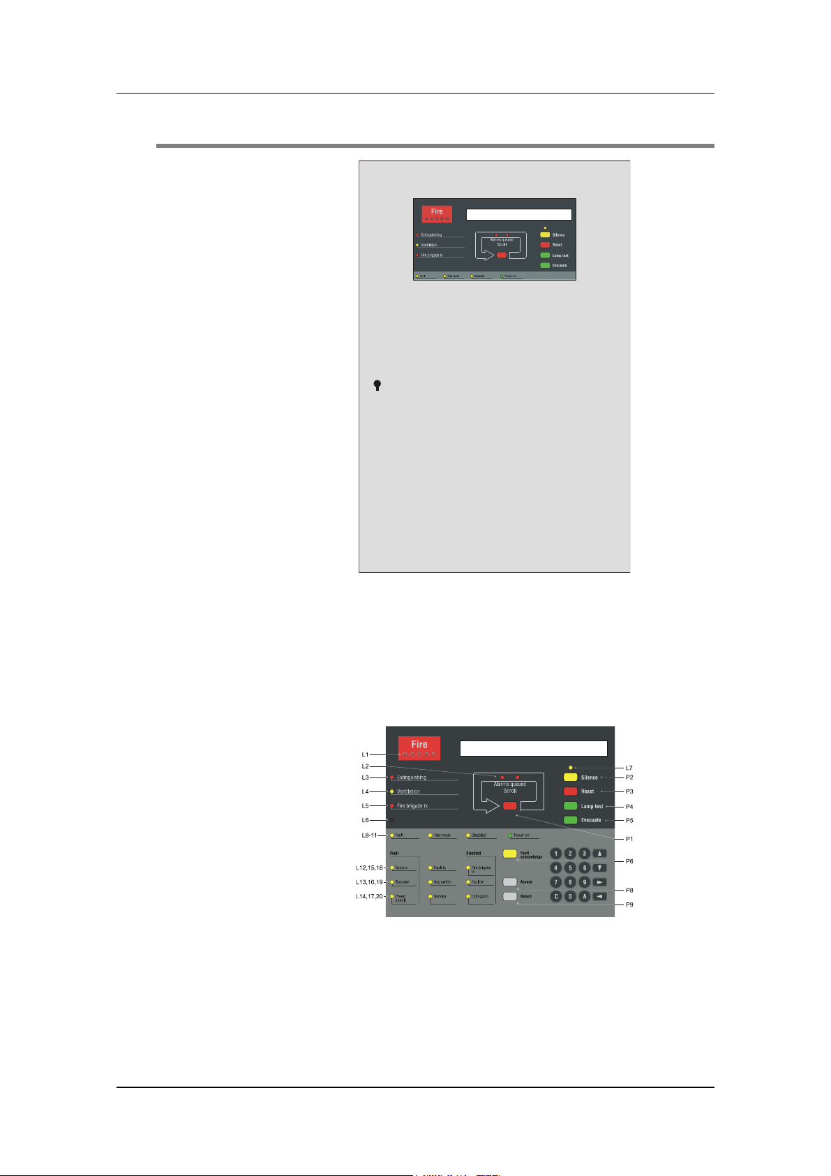
Figure 1. EBL512 Control Unit (1548 / 1549). The look may
vary according to configuration, country, etc.
The control unit (c.i.e.) is housed in a grey metal cabinet. The door
has a Plexiglas ahead of the FBP part, see Figure 1. When the door is
open, you fully see the front adhesive (the Fire Brigade Panel, FBP,
and Control Panel, CP), see Figure 2.
Figure 2. Front adhesive; FBP (upper black part) and CP (lower
grey part) in EBL512. The look may vary according to
configuration. (English config. in figure).
The fire brigade personnel use the FBP to see which alarm point(s)
having generated fire alarm. In the display (LCD, 2x40 alphanumeric
characters), is on the first row displayed the zone number and the
12

Matsushita Electric Works Fire & Security Technology AB
MEW00442 Rev: - Operating Instructions EBL512, V1.44.x
address within the zone. On the second row is shown a user definable
text message, if programmed.
Required fire brigade personnel manoeuvres can be performed from
the FBP.
The CP is used to "communicate" with the system, e.g. for
commissioning, monthly tests or maintenance. The CP has several
system status LEDs. A keypad is used to get access to the system (a
menu tree with main and sub menus) and for different manoeuvres.
Access codes for different access levels are required.
13
Matsushita Electric Works Fire & Security Technology AB
MEW00442 Rev: - Operating Instructions EBL512, V1.44.x
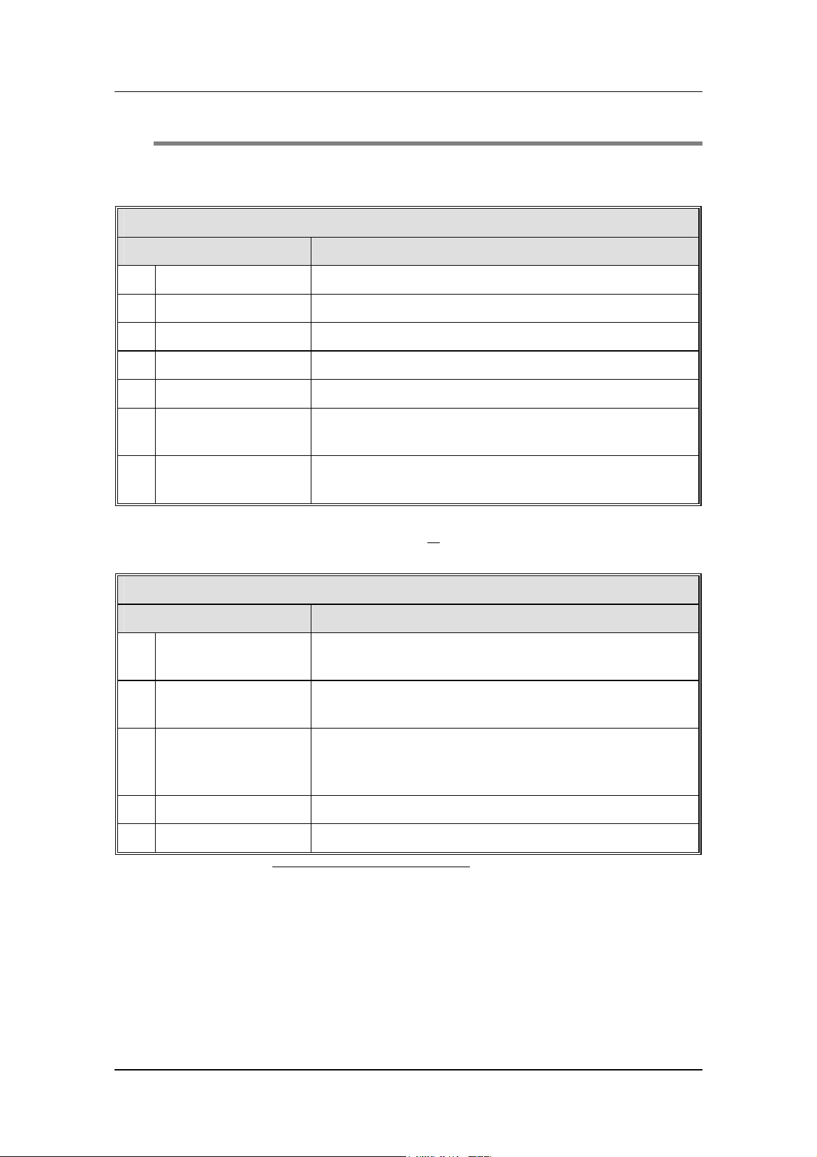
5 LED indicators and push buttons
LEDs and push buttons vary according to type and configuration
(convention / country / language).
LED indicators on the Fire Brigade Panel (FBP)
LED indicator Indicating
L1 Fire (5 red) Fire alarm generated.
L2 Alarms queued (2 red) More than one alarm point/zone have generated fire alarm.
L3 Extinguishing (red) Output(s) for extinguishing equipment activated.
L4 Ventilation (yellow) Output(s) for fire/smoke ventilation equipment activated.
L5 Fire brigade tx (red) Output(s) for fire brigade tx (routing equipment) activated
L6 (Zone/Detector not
5
reset)
(An alarm point has been reset while still in alarm status, i.e.
it is non-reset ("isolated") and has to be re-enabled.)
L7 Silence (yellow) The sounders (alarm devices) are silenced by the push button
"Silence".
L3-L5 can be individually programmed to indicate when it's normal
trigger condition is met or
when a programmable input is activated
(e.g. L5 will be turned on when an input is activated by a TX output.
Push buttons on the Fire Brigade Panel (FBP)
Push button Operation/function
P1 Scroll (red) Used, when LEDs "Alarms queued" are lit, to scroll/browse
through the queued alarms.
P2 Silence (yellow) 6 Used to silence the sounders (i.e. to "reset" resp. outputs).
LED "Silence" indicates silenced sounders.
P3 Reset (red) Resets the fire alarm displayed in the LCD. When more than
one fire alarm is generated (LEDs "Alarms queued" are lit).
Each fire alarm has to be individually reset.
P4 Lamp test (green) 7 To test all the LEDs on the FBP and the CP.
P5 Evacuate (green) 8 Manual activation of sounders (alt. Paper feed).
5
Normally only used in Swedish configuration / convention.
6
Has a special function in some configurations / conventions.
7
Not used in all configurations / conventions. If not used, it's black and has
no function.
8
Normally only used in Brittish Standard convention. In B.S. (Marine
application) convention it has the function "Paper feed". Otherwise it's black
and has no function (or the function "Paper feed").
14

Matsushita Electric Works Fire & Security Technology AB
MEW00442 Rev: - Operating Instructions EBL512, V1.44.x
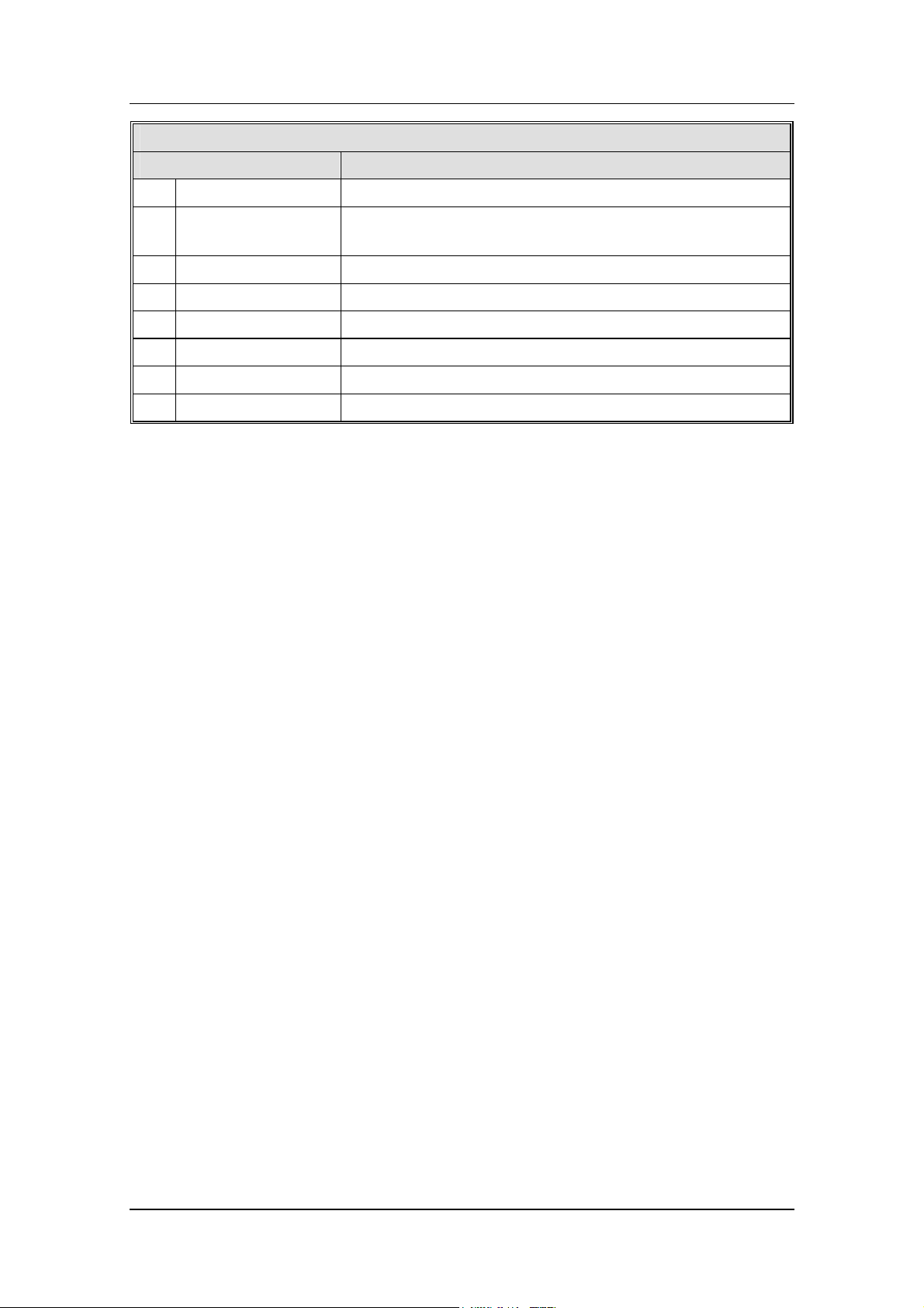
LED indicators on the Control Panel (CP)
LED indicator Indicating
L8 Fault (yellow) Acknowledged fault(s) and/or acknowledged but not
corrected fault(s).
L9 Test mode (yellow) One or more zones are in "test mode".
L10 Disabled (yellow) Something in the system is disabled.
L11 Power on (green) Power on, i.e. the power supply (rectifier and/or
battery are connected and working properly.
L12 Fault System (yellow) System program (SW) is not running correct (e.g.
CPU/memory fault).
L13 Fault Sounder (yellow) One or more supervised outputs (type 3=alarm
device) have generated fault.
L14 Fault Power supply (yellow) Power supply fault(s), described in chapter "Fault
messages", page 35.
L15 Fault tx (yellow) 1. One or more faults (not acknowledged) are
generated in the system.
2. Output(s) for fault tx (routing equipment) is(are)
activated.
L16 Key switch 9 (yellow)
(see chapter "Door open
(Key switch)", see page 25.
The control unit door is open. When a TLON
network is used, one or more doors in the system are
10
open.
L17 Service (yellow) One or more sensors have reached the service level.
L18 Disabled Fire brigade tx
(yellow)
Output(s) for fire brigade tx (routing equipment)
is(are) disabled via menu (H8/S1) or open door.
11
L19 Disabled Fault tx (yellow) Output(s) for fault tx (routing equipment) is(are)
disabled via menu (H8/S1) or open door.
11
L20 Disabled Extinguish Output(s) for extinguishing equipment is(are)
disabled via time channel or menu (H2/B3 or B8).
9
In Brittish Standard (Marine application) convention: "Door open".
10
It is programmable if also the ext. FBP open door(s) should be indicated
and if it should indicate for each control unit individually or the whole
system.
11
It is programmable if open door should disable the output(s).
15
Matsushita Electric Works Fire & Security Technology AB
MEW00442 Rev: - Operating Instructions EBL512, V1.44.x
Keypad/push buttons on the Control Panel (CP)
Key/push button Operation/function
0 - 9 Numeric keys for the figures 0-9.
← →
↑ ↓
Left / right keys to move the cursor in a menu.
Up / down keys to scroll between the menus.
C Clear /deletes just written data.
A Accept a menu and accept input of data.
P6 Fault acknowledge Fault acknowledge (menu H6).
P7 - -
P8 Access To get access to the menu tree (via access code).
P9 Return To leave a menu ("one step up") and to stop input of data.
16
Matsushita Electric Works Fire & Security Technology AB
MEW00442 Rev: - Operating Instructions EBL512, V1.44.x
6 Access levels
The control unit has five access levels which are adapted to different
kind of users.
Access level 1 Open door
Fire brigade personnel Fire alarm handling
(key is needed)
Access level 2 Access code for
Building occupier Installation handling,
level 2 (or 3 or 4)
is required
Access level 3 Access code for
Service personnel Service, maintenance
level 3 (or 4) is
required
Access level 4 Access code for
level 4 is
required
Access level 5 Access code for
level 5 is
required
Service /
commissioning
engineer
Service /
commissioning
engineer
The access codes can be changed. To change a code you have to
know the valid code or use a code for a higher access level.
6.1 Access level 1
After the door has been opened (LED "Key switch" is lit), the user /
fire brigade personnel will be able to use the push buttons / keypad to:
monthly tests, etc.
Service, commissioning
the system, etc.
Code to connect a PC,
i.e. for Win512.
Scroll / browse through the queued alarms.
Silence the sounders (alarm devices).
Reset fire alarm(s).
Perform lamp (LED) test.12
Start the sounders.13
Get access (after login) to certain menus / functions in the system.14
12
Not in all configurations / conventions.
13
Normally only used in English configuration / convention.
14
Normally, the fire brigade personnel have no access code.
17

Matsushita Electric Works Fire & Security Technology AB
MEW00442 Rev: - Operating Instructions EBL512, V1.44.x
6.2 Access level 2
From access level 1, the user can login to access level 2, which gives
access to the following menus:
H1 Perform monthly test.
H2 Disable or re-enable.
B1 Disable zone
B2 Disable zone / address
B3 Disable control output
B4 Re-enable zone
B5 Re-enable zone / address
B6 Re-enable control output
B7 Re-enable non-reset zone / address15
B8 Control on / Control off
B9 Alarm device on / Alarm device off
H3 Set calendar and clock.
H4 Present system status on display and printer.
U1 Disablement
U2 Disablement by time channel.
U3 Show open doors.16
U4 Activated 2-zone / address dependent zone / address.
U5 Show sensors week average values.
U6 Show sensors momentary values.
U7 Sensors activating service signal
U8 Show event log
U9 Show configuration
H6 Acknowledge faults.
H7 Perform zone test (Test mode).
H9 Change access code for daily duties (access level 2).
15
Normally only in Swedish configuration / convention.
16
When a TLON network is used, one or more doors in the system could be
open. It is programmable if also ext. FBP open door(s) should be indicated
and if it should indicate for each control unit individually or the whole
system. See also chapter Door open (Key switch), page 25.
18

Matsushita Electric Works Fire & Security Technology AB
MEW00442 Rev: - Operating Instructions EBL512, V1.44.x
6.3 Access level 3
From access level 217, the user can login to access level 3, which gives
access to the following menus, normally used by service personnel:
Same menus as in access level 2 plus the following:
H8 Maintenance
S1 Disable or re-enable outputs for routing equipment (Fire
brigade tx & Fault tx)
S2 Disconnect COM loop.
S3 Re-connect Loop.
S4 Acknowledge service signal.
S5 Safe shut down of control unit.
S6 Activate address in alarm mode.
S7 Synchronize the control units.
S8 Change access code for maintenance (access level 3).
17
If code for access level 3 or 4 has been used to login to access level 2, new
login to access level 3 is not required.
19

Matsushita Electric Works Fire & Security Technology AB
MEW00442 Rev: - Operating Instructions EBL512, V1.44.x
6.4 Access level 4
From access level 218, the user can login to access level 4, which gives
access to the following menus, normally used by a Service /
Commissioning Engineer:
Same menus as in access level 2 and 3 plus the following:
H5 Programming
A1 Calibration of monitored outputs
A2 Sensitive fault detection mode
A3 Direction for communication on COM loop (and BS4 loop)
A4 Show information about site specific data.
A5 Display current consumption in unit
A6 Display current consumption on COM-/BS4-loop
A7 Display statistics for COM-loop
A8 Select unit on COM-loop (and BS4 loop) to use for triggering
A9 Change access code for PC-communication (access level 5).
A10 Change access code for programming (access level 4).
6.5 Access level 5
Used by Service / Commissioning Engineer when a PC is to be
connected to the control unit, i.e. when Win512 is to be used for
backup, downloading site specific data, downloading SW / settings /
configurations / C.U. and system data, on-line status checking, etc.
18
If code for access level 4 has been used to login to access level 2, new
login to access level 4 is not required.
20

Matsushita Electric Works Fire & Security Technology AB
MEW00442 Rev: - Operating Instructions EBL512, V1.44.x
7 Normal operation
When the control unit / system is in normal operation, i.e. no fire
alarm, no fault, no disablement, no service signal, not in test mode and
no open doors, etc., only the LED "Power on" (L11) is to be lit.
21

Matsushita Electric Works Fire & Security Technology AB
MEW00442 Rev: - Operating Instructions EBL512, V1.44.x
8 Push button "Silence"
In the control unit (on the FBP) there is a push button (P2) "Silence"
and an LED (L7) "Silence". In some configurations / conventions,
this button could have special function(s).
8.1 Silence before a fire alarm
19
If the push button "Silence" is pushed before a fire alarm / fault,
the following will happen:
• LEDs "Silence" and "Disabled" (L10) will light up (steady
ON)
• the buzzer in the control unit will be disabled
• outputs programmed for sounders (type 3 = alarm devices)
will be disabled
If case of a fire alarm, the buzzer and the sounders will remain turned
OFF (not sound).
In case of a fault, the buzzer will remain turned OFF (not sound).
To reset this function, push "Silence" once more. The LEDs will be
turned OFF, indicating a normal state.
8.2 Silence during a fire alarm
If the push button "Silence" is pushed during a fire alarm, the
following will happen:
• LEDs "Fire" and "Alarms queued"
blinking to steady ON
• the buzzer in the control unit will be turned OFF
• activated outputs, programmed for sounders (type 3 = alarm
devices), will be turned OFF
In case of a new fire alarm
again, the buzzer and the sounders (i.e. the outputs), will automatically
be turned ON and LEDs "Fire" and "Alarms queued" starts blinking.
If the push button "Silence" is pushed during a fault condition, the
following will happen:
• the buzzer in the control unit will be turned OFF
It will be turned OFF until the push button "Silence" is pushed again
(or a fire alarm is activated).
, or if the push button "Silence" is pushed
20
(L2) changes from
19
In some configurations / conventions, e.g. Swedish (RUS), Brittish
Standard and B.S. (Marine application) is this function not valid.
20
When more than one fire alarm is activated.
22

Matsushita Electric Works Fire & Security Technology AB
MEW00442 Rev: - Operating Instructions EBL512, V1.44.x
9 Alarm device on / Alarm device off
Via menu H2/B9, all outputs, programmed for sounders (type 3 =
alarm devices), can be turned OFF (disabled).
In case of a fire, the sounders will remain turned OFF (not sound).
They will be turned OFF (disabled) until they are turned ON (reenabled) again, via menu H2/B9.
Alarm device OFF is indicated by LED "Disabled" (L10).
23

Matsushita Electric Works Fire & Security Technology AB
MEW00442 Rev: - Operating Instructions EBL512, V1.44.x
10 Controls ON / Controls OFF
Via menu H2/B8, all control output types:
0 = control (general)
1 = fire ventilation
21
2 = extinguishing system
can be collective turned OFF (disabled).
They will be turned OFF (disabled) until they are turned ON (reenabled) again, via menu H2/B8.
Controls OFF is indicated by LED "Disabled" (L10).
21
Also the "Extinguish equipment output" on the German FBP interface
board 1583.
24

Matsushita Electric Works Fire & Security Technology AB
MEW00442 Rev: - Operating Instructions EBL512, V1.44.x
11 Door open (Key switch)
A key is used to open the control unit door to get access to the system,
see chapter "Access levels", page 17.
Door open is indicated by LED "Key switch" (L16), see below.
Door open can disable output(s) for fire alarm and fault routing
equipment respectively. LEDs "Fire brigade tx Disabled" and "Fault
tx Disabled" indicate this respectively. See below.
11.1 LED "Key switch"
In Win512, the following can be programmed:
Door in any control unit in the system
LED "Key switch" is indicating door open in one or more control
units in the system.
or
Door in control unit
LED "Key switch" is indicating door open in the same control unit as
the LED is situated.
Indication open door external FBP
In both cases above could be chosen, if an open door in one or more
external FBPs should be indicated by the LED "Key switch", or not.
11.2 Disable outputs for routing equipment (Fire
brigade tx and Fault tx)
In Win512, the following can be programmed:
No disabling
Output(s) for routing equipment (Fire brigade tx and Fault tx), are not
disabled by an open door.
or
Disable if any door in the system is open
Output(s) for routing equipment (Fire brigade tx and Fault tx), are
disabled when a door in a control unit is open
22
.
Disabled outputs for routing equipment are indicated by the LED
"Disabled", "Fire brigade tx Disabled" (L18) and "Fault tx Disabled"
(L19).
22
No choice between control unit and any control unit in the system. Only
valid for control unit doors, not ext. FBP doors.
25
Matsushita Electric Works Fire & Security Technology AB
MEW00442 Rev: - Operating Instructions EBL512, V1.44.x
12 Technical number / Presentation
number
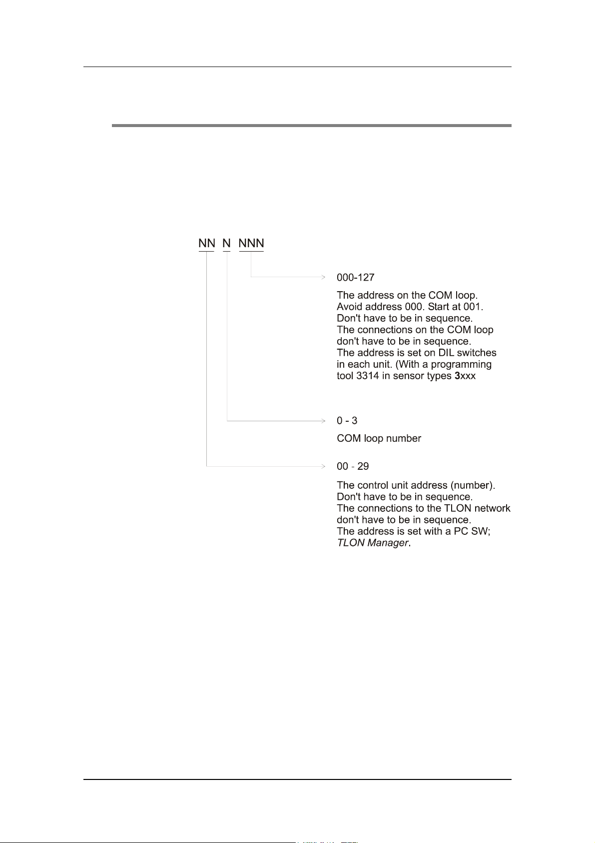
12.1 Technical number for COM loop units
The technical number, NNNNNN, is used when programming all
units connected to the COM loops.
Technical number is also used to identify which unit has generated a
fault.
Regarding DIL-switch address setting, see dwg 512-71.
26
Matsushita Electric Works Fire & Security Technology AB
MEW00442 Rev: - Operating Instructions EBL512, V1.44.x
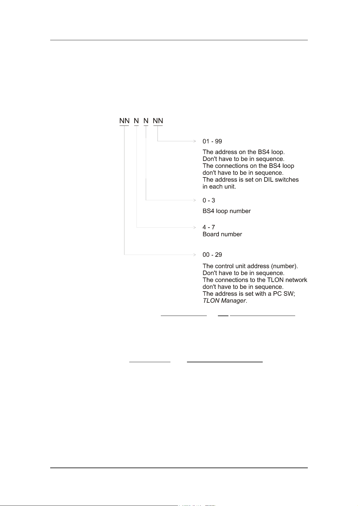
12.2 Technical number for BS4 loop units
Autronica interface board 1584 (four BS4 loops) is required in the
control unit.
The technical number, NNNNNN, is used when programming all
units connected to the BS4 loops.
Technical number is also used to identify which unit has generated a
fault.
NOTE! In the technical number
board number 4 = Autronica interface board 0, the board number 5 =
Autronica interface board 1, the board number 6 = Autronica interface
board 2 and the board number 7 = Autronica interface board 3 in the
control unit.
In fault messages
information is shown: Control unit (00-29), BS4 board (0-3) and if
required BS4 loop (0-3)
for Autronica interface boards, the following
for unit connected to a BS4 loop, the
27
Matsushita Electric Works Fire & Security Technology AB
MEW00442 Rev: - Operating Instructions EBL512, V1.44.x
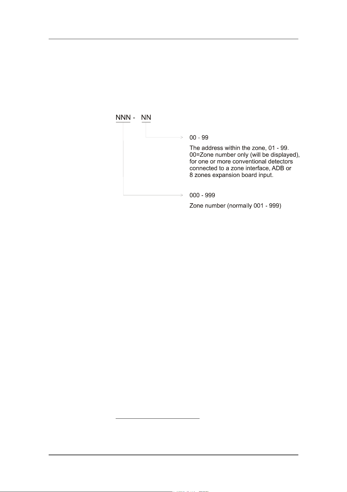
12.3 Presentation number
For each fire alarm point / input, a presentation number, NNN-NN,
has to be programmed. This number is shown in the FBP display(s)
23
to identify the point / zone generating fire alarm. It is also used to
disable / re-enable fire alarm points / zones and in control conditions
(expressions) to activate the programmable outputs.
Together with the zone number and the address, a user definable, 40
character, text message can be displayed (if programmed).
,
23
Presentation number is also shown in the display units connected to the
COM loops.
28
 Loading...