

NAIS DSBT2-M-DC1.5V, DSBT2-S-DC12V, DSBT2-S-DC1.5V, DSBT2-M-DC9V, DSBT2-M-DC6V Datasheet
...
TESTING
4,000 V BREAKDO WN
VOLTAGE DS RELAYS
20.65
.813
10.65
.419
10.5
.413
mm inch
SPECIFICATIONS
Contact
Arrangement 2 Form C 2 Form D
Initial contact resistance, max.
(By voltage drop 6 V DC 1 A)
Contact material Gold-clad silver
Nominal switching capacity
Rating
(resistive
load)
Max. switching power 60 W, 125 VA 30 W, 62.5 VA
Max. switching voltage 220 V DC, 250 V AC
Max. switching current 2 A 1 A
Min. switching capacity**
Electrical
life (min.
ope.)
1
**
This value can change due to the switching frequency, environmental
Mechanical (at 180 cpm) 2 × 10
Electrical (at 20 cpm) 2 × 10
2 A 30 V DC 1 A 30 V DC
1
conditions, and desired reliability level, therefore it is recommended to
check this with the actual load.
Coil
Arrangement 2 Form C 2 Form D
Nominal operating power 360 mW 540 mW
Remarks
* Specifications will vary with foreign standards certification ratings.
1
*
Measurement at same location as "Initial breakdown voltage" section
2
*
Detection current: 10mA
3
Excluding contact bounce time
*
4
*
Half-wave pulse of sine wave: 11ms, detection time: 10 µ s
5
Half-wave pulse of sine wave: 6ms
*
6
*
Detection time: 10 µ s
7
Refer to 5. Conditions for operation, transport and storage mentioned in
*
AMBIENT ENVIRONMENT (Page 61)
50 m Ω
10 µ A 10 mV DC
7
5
10
6
DS-BT
RELAYS
FEATURES
•4,000 V breakdown voltage
•Reinforced insulation between coil and contacts
•Surge voltage withstand: 1500 V FCC Parts 68
Characteristics
Arrangement 2 Form C 2 Form D
Max. operating speed 60 cpm at rated load
Initial insulation resistance*
Initial
breakdown
voltage*
Between open contacts
Between contacts and coil
2
Between contacts sets
FCC surge voltage between open
contacts
Operate time*
3
(at nominal volt-
age)
Release time (without diode)*
(at nominal voltage)
Temperature rise Max. 65 ° C
Vibration
resistance
Shock
resistance
Conditions for operation, transport and
7
storage*
(Not freezing and
condensing at low
temperature)
Unit weight Approx. 4.0 g 0.14 oz
1
Min. 100 M Ω (at 500 V DC)
750 Vrms
for 1 min.
500 Vrms
for 1 min.
4,000 Vrms for 1 min.
750 V 500 V
1,500 V
Approx. 3 ms
3
Functional*
Destruction*
Functional*
4
at double amplitude of 3.3 mm
5
6
Destruction Min. 980 m/s
Ambient
temp.
–40 ° C to +70 ° C
–40 ° F to +158 ° F
Approx. 2 ms
10 to 55 Hz
10 to 55 Hz
at double amplitude of 5 mm
Min. 294 m/s
2
(30 G)
2
(100 G)
–40 ° C to +60 ° C
–40 ° F to +140 ° F
Humidity 5 to 85%R.H.
TYPICAL APPLICATIONS
Modem
Facsimile
Telecommunication equipment
192
ORDERING INFORMATION
2DSBT M
Contact
arrangement
2: 2 Form C or
2 Form D
Note: Standard packing; Carton: 25 pcs. Case 1,000 pcs.
Sensitivity MBB function Coil voltage
S: 360 mW
(2 Form C only)
M: 540 mW
(2 Form D only)
Nil: BBM (Form C)
2D: 2MBB
(2 Form D)
2D DC3V
DC 1.5, 3, 5,
6, 9, 12, 24 V
Ω ( ±
Ω ( ±
DS-BT
TYPES AND COIL DATA
(at 20 ° C 68 ° F)
1) 2 Form C type
Operating
function
Single side
stable
Part No.
DSBT2-S-DC1.5V 1.5 1.125 0.15 240 6.25
DSBT2-S-DC3V 3 2.25 0.3 120 25 3.9
DSBT2-S-DC5V 5 3.75 0.5 72 69.4 6.5
DSBT2-S-DC6V 6 4.5 0.6 60 100 7.8
DSBT2-S-DC9V 9 6.75 0.9 40 225 11.7
DSBT2-S-DC12V 12 9 1.2 30 400 15.6
DSBT2-S-DC24V 24 18 2.4 15 1,600 31.2
Coil voltage,
V DC
2) 2 Form D type
Operating
function
Part No.
DSBT2-M-2D-DC1.5V 1.5 1.125 0.15 360 4.2
DSBT2-M-2D-DC3V 3 2.25 0.3 180 16.7 3.6
Single side
stable
DSBT2-M-2D-DC5V 5 3.75 0.5 108 46.3 6
DSBT2-M-2D-DC6V 6 4.5 0.6 90 66.7 7.2
DSBT2-M-2D-DC9V 9 6.75 0.9 60 150 10.8
DSBT2-M-2D-DC12V 12 9 1.2 45 266.7 14.4
DSBT2-M-2D-DC24V 24 18 2.4 22.5 1,066.7 28.8
Note: Standard packing Tube: 25 pcs. Case: 1,000 pcs.
Coil voltage,
V DC
Pick-up
voltage,
V DC (max.)
Pick-up
voltage,
V DC (max.)
Drop-out
voltage,
V DC (min.)
Drop-out
voltage,
V DC (min.)
Nominal operating
current,
mA ( ± 10%)
Nominal operating
current,
mA ( ± 10%)
Coil
resistance,
10%)
Coil
resistance,
10%)
Nominal
operating
power, mW
360
Nominal
operating
power, mW
540
Max. allowable
voltage, V DC
(at 50 ° C 122 ° F)
1.95
Max. allowable
voltage, V DC
(at 50 ° C 122 ° F)
1.8
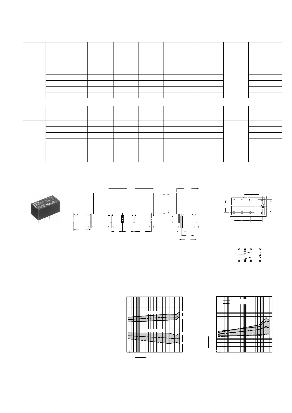
DIMENSIONS
7.62
.300
REFERENCE DATA
1. Mechanical life test
Tested sample: DSBT2-S-DC5V, 10 pcs.
Coil applied voltage: 5 V DC
Operating frequency: 30 cpm
0.30
.012
PC board pattern (Bottom view)
3.4
.134
10.65
.419
0.6
.024
2
.079
5.6
.220
7.82
.308
0.35
.014
7.62
.300
Schematic (Bottom view)
.024
0.6
5.08
.200
5.08
.200
20.65
.813
7.62
.300
0.3
.012
10.50
.413
9.9
.390
General tolerance: ± 0.3 ± .012
Change of pick-up and drop-out voltage Change of contact resistance
4
3
2
Pick-up/drop-out voltage, V DC
1
Pick-up voltage Max.
Drop-out voltage
–
x
Min.
Max.
–
x
Min.
100
Contact resistance, mΩ
10
8-0.9 dia.
8-.035 dia.
5.08
5.08
.200
7.62
.300
.200
Tolerance: ± 0.1 ± .004
9
11
N.O.13COM16–
N.C.
N.O.
COM
N.C.
8
N.C. contact
N.O. contact
+
4
6
1
mm inch
7.82
.308
Max.
Max.
–
x
–
x
Min.
Min.
0
No. of operations, × 10
1000100100
4
0
No. of operations, × 10
1000100100
4
193
 Loading...