

NAIS CA1bS-12V-N-5, CA1bS-12V-C-5, CA1bS-12V-A-5, CA1bFS-12V-N-5, CA1bFS-12V-C-5 Datasheet
...
383
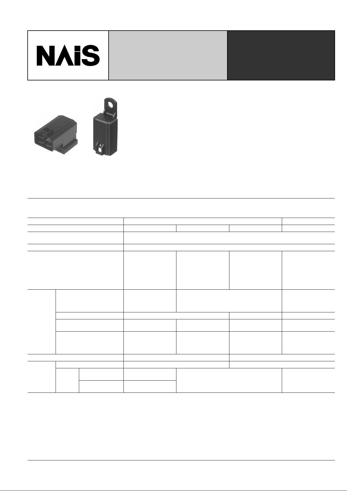
CA-RELAYS
AUTOMOTIVE POWER
RELAYS — SMALL SIZE,
LIGHT WEIGHT AND
COMPLETEL Y W A TER TIGHT
FEATURES
1. Small size and light weight
For space saving, the outside dimensions
of the main body are reduced to be 21.5
mm (length) × 14.4 mm (width) × 37 mm
(height) (.846 × .567 × 1.457 inch). and
the weight is also reduced to be approx.
19 g .67 oz (Direct coupling 1 Form A,
1 Form B type)
2. W ater tightness
Since the relays comply with the water
tightness standards, JIS D 0203, water
and dust will not enter the relay ev en if it is
mounted in the engine area.
3. Low operaing power (1.4W) type is
available (1 Form A, 1 Form B)
4. Since the terminal arrangement
complies with JIS D5011 B4-M1, commercial connectors are available for
these types of relays.
SPECIFICATIONS
Contact
Type 12 V DC 24 V DC
Arrangement 1 Form A 1 Form B 1 Form C 1 Form C
Initial contact resistance, max.
(By voltage drop 6 V DC 1A)
50 m ohm
Contact material silver alloy
Contact voltage drop, max.
0.3 V
After electrical life test,
by voltage drop
12 V DC 20 A
(1.4 W type),
12 V DC 30 A
(1.8 W type)
0.3 V
After electrical life test,
by voltage drop
12 V DC 20 A
0.4 V
After electrical life test,
by voltage drop
12 V DC 20 A
0.4 V
After electrical life test,
by voltage drop
24 V DC 10 A
Rating
Nominal switching capacity
(resistive load)
20 A 12 V DC
(1.4 W type)
30 A 12 V DC
(1.8 W type)
20 A 12 V DC
10 A 24 V DC
(ON: 2s, OFF: 2s)
Max. switching voltage 16 V 15 V 30 V
Max. switching current
120 A (1.4 W type)
150 A (1.8 W type)
120 A 100 A 50 A (Inrush current)
Max. carrying current
20 A continuous
(1.4 W type)
30 A for 1 min
(1.8 W type)
20 A continuous 20 A continuous 10 A continuous
Nominal operating power 1.4 W / 1.8 W 1.8 W
Expected
life (min.
operations)
Mechanical (at 120 cpm) 10
6
5 ×
10
5
Electrical
20 A
(1.4 W, 1.8 W type)
10
5
(ON: 2s, OFF: 2s)
10
5
(ON 2s, OFF 2s) 10
5
30 A
(1.8 W type)
2 × 10
4
(ON: 3s, OFF: 15s)
CA
384
Characteristics (at 20 ° C 68 ° F )
Electrical life (min. operation)
Remarks
* Specifications will vary with foreign standards certification ratings.
*
1
Detection current: 10 mA
*
2
Excluding contact bounce time
*
3
Half-wave pulse of sine wave: 11ms; detection time: 10 µ s
*
4
Half-wave pulse of sine wave: 6ms
*
5
Detection time: 10 µ s
*
6
Refer to 5. Conditions for operation, transport and storage mentioned in
AMBIENT ENVIRONMENT (Page 61)
Type 12 V DC 24 V DC
Max. operating speed
15 cpm 1.4 W type: at nominal load
1.8 W type: at 20 A
15 cpm (at nominal load)
Initial insulation resistance Min. 10 Ω at 500 V DC
Initial breakdown
voltage*
1
Between open contacts
500 V rms for 1 min.
Between contacts and coil
500 V rms for 1 min.
Operate time*
2
(at nominal voltage) Max. 10 ms at 20 ° C Max. 10 ms
Release time (without diode)*
2
(at nominal voltage)
Max. 10 ms at 20 ° C Max. 10 ms
Shock resistance
Functional Min. 200 m/s
2
{20 G} Min. 100 m/s
2
{10 G} Min. 100 m/s
2
{10 G}*
3
Destructive*
4
Min. 1,000 m/s
2
{100 G}
Vibration resistance
Functional*
5
Rubber bracket A type: Min. 100 m/s
2
{10 G}, 50 to 500Hz
Direct coupling type or Screw-mounting type: Min. 44.1 m/s
2
{4.5 G}, 10 to 100 Hz
Min. 44.1 m/s
2
{4.5 G},
10 to 100Hz
Destructive
Rubber bracket A type: Min. 100m/s
2
{10 G},50 to 500Hz
Direct coupling type or Screw-mounting type: Min. 44.1 m/s
2
{4.5 G}, 10 to 100 Hz
Min. 44.1 m/s
2
{4.5 G},
10 to 500Hz
Conditions for operation,
transport and storage*
6
(Not freezing and condensing
low temperature)
Ambient
temp.
–30 ° C to +80 ° C –22 ° F to +176 ° F
Humidity 5 to 85% R.H.
Water-proof standard Plastic sealed type: JIS DO203S2, Dust cover type: JIS DO203R2 JIS DO203S2
Unit weight
Rubber bracket A type : 23 g .81 oz
Direct coupling type or Screw-mounting type:
19 g .67 oz
31 g 1.09 oz
Nominal coil voltage, V DC
Motor load
(operating frequency ON: 2 s, OFF: 2 s)
Halogen lamp load
(operating frequency ON: 1 s, OFF: 14 s)
1 Form A, 1 Form B 12 10
5
, 20 A 12 V DC 10
5
, 20 A 12 V DC
1 Form C
12 10
5
, 20 A 12 V DC 10
5
, 20 A 12 V DC
24 10
5
, 10 A 24 V DC 10
5
, 6 A 24 V DC
ORDERING INFORMATION
CA 1a F S 12 V A 5
Contact
arrangement
Notes: 1. Type with resistor/diode inside are available as options. Please consulf our sales office.
2. Standard packing: Carton: 20 pcs. Case: 200 pcs.
Mounting method
Classification by type
1a: 1 Form A
1b: 1 Form B
1 : 1 Form C
Protective construction
Nil: Plastic sealed type
F: Dust cover type
Coil voltage
(DC)
12 V
24 V (1 Form C only)
Nil: 1 Form C
5: 1 Form A or
1 Form B
Nominal operating power
Nil: Standard type (1.8 W)
S: Low operating power type (1.4 W)
(1 Form A, 1 Form B)
A: Rubber bracket A type
A: (1 Form A, 1 Form B)
N: Screw mounting type
C: Direct coupling type
COIL DATA
1) Standard type
Contact
arrangement
Mounting type
Plastic sealed
type
Dust cover type
Nominal
voltage,
V DC
Pick-up voltage,
V DC (max.)
(at 20
°
C 68 ° F)
Drop-out
voltage, V DC
(min.)
(at 20
°
C 68 ° F)
Nominal oper-
ating current,
mA (
±
10%)
(at 20
°
C 68 ° F)
Coil resistance,
Ω ( ±
10%)
(at 20
°
C 68 ° F)
Nominal
operating
power, mW
(at 20
°
C 68 ° F)
Usable
voltage
range, V
DC
1 Form A
Rabber bracket A CA1a-12V-A-5 CA1aF-12V-A-5 12 8 0.6 to 6 150 80 1.8 10 to 16
Screw-mounting CA1a-12V-N-5 CA1aF-12V-N-5 12 8 0.6 to 6 150 80 1.8 10 to 16
Direct coupling CA1a-12V-C-5 CA1aF-12V-C-5 12 8 0.6 to 6 150 80 1.8 10 to 16
1 Form B
Rabber bracket A CA1b-12V-A-5 CA1bF-12V-A-5 12 8 0.6 to 6 150 80 1.8 10 to 16
Screw-mounting CA1b-12V-N-5 CA1bF-12V-N-5 12 8 0.6 to 6 150 80 1.8 10 to 16
Direct coupling CA1b-12V-C-5 CA1bF-12V-C-5 12 8 0.6 to 6 150 80 1.8 10 to 16
1 Form C
Screw-mounting CA1-DC12V-N – 12 8 0.6 150 80 1.8 10 to 15
Direct coupling CA1-DC12V-C – 12 8 0.6 150 80 1.8 10 to 15
Screw-mounting CA1-DC24V-N – 24 16 1.2 75 320 1.8 20 to 30
Direct coupling CA1-DC24V-C – 24 16 1.2 75 320 1.8 20 to 30
()

CA
385
2) Low operating power type
DIMENSIONS
1. 1 Form A/1 Form B
Rubber bracket A type
Contact
arrangement
Mounting type
Plastic sealed
type
Dust cover type
Nominal
voltage,
V DC
Pick-up voltage,
V DC (max.)
(at 20
°
C 68 ° F)
Drop-out
voltage, V DC
(min.)
(at 20
°
C 68 ° F)
Nominal oper-
ating current,
mA (
±
10%)
(at 20
°
C 68 ° F)
Coil resistance,
Ω ( ±
10%) (at
20
°
C 68 ° F)
Nominal
operating
power, mW
(at 20
°
C 68 ° F)
Usable
voltage
range, V
DC
1 Form A
Rabber bracket A CA1aS-12V-A-5 CA1aFS-12V-A-5 12 8 0.6 to 6 120 100 1.4 10 to 16
Screw-mounting CA1aS-12V-N-5 CA1aFS-12V-N-5 12 8 0.6 to 6 120 100 1.4 10 to 16
Direct coupling CA1aS-12V-C-5 CA1aFS-12V-C-5 12 8 0.6 to 6 120 100 1.4 10 to 16
1 Form B
Rabber bracket A CA1bS-12V-A-5 CA1bFS-12V-A-5 12 8 0.6 to 6 120 100 1.4 10 to 16
Screw-mounting CA1bS-12V-N-5 CA1bFS-12V-N-5 12 8 0.6 to 6 120 100 1.4 10 to 16
Direct coupling CA1bS-12V-C-5 CA1bFS-12V-C-5 12 8 0.6 to 6 120 100 1.4 10 to 16
21.5
.846
19.5
.768
9
.354
37
1.457
14.4
.567
17.4
.685
10
.394
15
.591
2.5
.098
6
.236
21.5
.846
17
.669
0.8
.031
15.4
.606
12.4
.488
5.5
.217
2.4
.094
1.5
.059
2
.079
Sealed with
epoxy resin
Dimension:
General tolerance
Max. 1mm .039 inch:
±
0.1 ± .004
1 to 3mm .039 to .118 inch: ± 0.2 ± .008
Min. 3mm .118 inch:
±
0.3 ± .012
mm inch
SCHEMATIC (Bottom View)
1 Form A
Including load
(1 Form A)
Including diode
(1 Form C)
1 Form B
Including diode type, including load type also available.
2. 1 Form A/1 Form B
Screw-mounting type
14
.551
9
.354
2 .079
17.4
.685
21.5 .846
3 .118
14.4
.567
6 .236
0.8
.031
15.4
.606
12.4
.488
5.5
.217
2.4
.094
17.5
.689
37
1.457
7
.276
R10
6.5 dia. hole
+0.3
–0
.256 dia.
+.012
–0
Sealed with
epoxy resin
19.5 .768
Dimension: General tolerance
Max. 1mm .039 inch:
±
0.1 ± .004
1 to 3mm .039 to .118 inch: ± 0.2 ± .008
Min. 3mm .118 inch:
±
0.3 ± .012
SCHEMATIC (Bottom View)
1 Form A
Including load
(1 Form A)
Including diode
(1 Form C)
1 Form B
Including diode type, including load type also available.

CA
386
3. 1 Form A/1 Form B
Direct coupling type
21.5
.846
9
.354
17.4
.685
14.4
.567
6 .236
0.8
.031
15.4
.606
12.4
.488
5.5
.217
2.4
.094
37
1.457
Sealed with
epoxy resin
19.5 .768
Dimension:
General tolerance
Max. 1mm .039 inch:
±
0.1 ± .004
1 to 3mm .039 to .118 inch: ± 0.2 ± .008
Min. 3mm .118 inch:
±
0.3 ± .012
mm inch
SCHEMATIC (Bottom View)
1 Form A
Including load
(1 Form A)
Including diode
(1 Form C)
1 Form B
Including diode type, including load type also available.
4. 1 Form C
Screw-mounting type
14
.551
23.4
.921
19.4
.764
31.2 1.228
4
.157
2
.079
5.5
.217
2.4
.094
0.8
.031
12.2
.480
12
.472
40
1.575
59
2.323
28
1.102
R10
6.6 dia. hole
.260 dia.
28.4 1.118
20
.787
9
.3549.354
6
.236
11.4
.449
Sealed with
epoxy resin
Dimension: General tolerance
Max. 1mm .039 inch:
±
0.1 ± .004
1 to 3mm .039 to .118 inch: ± 0.2 ± .008
Min. 3mm .118 inch:
±
0.3 ± .012
SCHEMATIC (Bottom View)
Including diode type, including load type also available.
Including load
(1 Form C)
Including diode
(1 Form A)
1 Form C
5. 1 Form C
Direct coupling type
19.4
.764
5.5
.217
2.4
.094
0.8
.031
12.2
.480
40
1.575
28
1.102
9
.3549.354
6
.236
11.4
.449
Sealed with
epoxy resin
23.4
.921
31.2 1.228
28.4 1.118
Dimension: General tolerance
Max. 1mm .039 inch:
±
0.1 ± .004
1 to 3mm .039 to .118 inch: ± 0.2 ± .008
Min. 3mm .118 inch:
±
0.3 ± .012
SCHEMATIC (Bottom View)
Including diode type, including load type also available.
Including load
(1 Form C)
Including diode
(1 Form A)
1 Form C

CA
387
REFERENCE DATA
1. Coil temperature rise
Tested sample: CA1aS-12V-N-5, 5 pcs.
Point measured: Inside the coil
Contact carrying current: 20A
Ambient temperature: Room temperature,
85°C 185°F
2. Electrical life test (Motor load)
Tested sample: CA1a-12V-N-5, 5 pcs.
Load: Steady 30A, Inrush 150A, 12V DC
Operate frequency: ON 3s, OFF 15s
Ambient temperature: Room temperature
12 14 16
140
120
100
80
60
40
20
0
85°C
185°F
Room
temperature
Temperature rise, °C
Coil applied voltage, V
0
2
4
6
8
10
02
X
X
Max.
Max.
Min.
Min.
Pick-up and drop-out voltage, V
No. of operations, ×10
4
Contact welding: 0 times
Miscontact: 0 times
Pick-up voltage
Drop-out voltage
For Cautions for use, see Relay Technical Information (Page 48 to 76).
9/1/2000 All Rights Reserved, © Copyright Matsushita Electric Works, Ltd.
Go To Online Catalog
 Loading...