

NAIS AQV254RAZ, AQV254RAX Datasheet
177
1
2
3
6
5
4
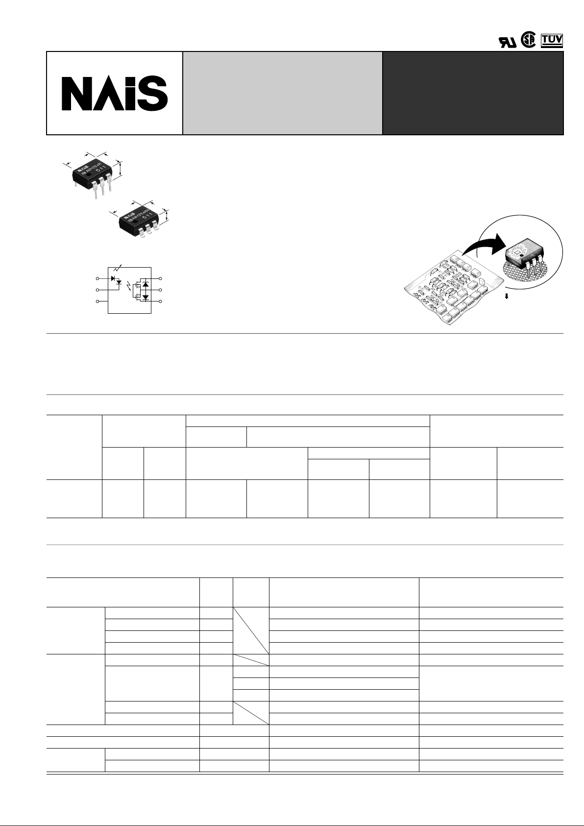
HE (High-function Economy)
Type
[1-Channel (Form A) Type]
—With LED Display—
8.8±0.05
.346±.002
6.4±0.05
.252±.002
3.9±0.2
.154±.008
8.8±0.05
.346±.002
6.4±0.05
.252±.002
3.6±0.2
.142±.008
mm inch
FEATURES
• Low on resistance and LED display
• Same compact size of our conventional relays without LED display
(W) 6.4 × (D) 8.8 × (H) 3.9 mm (W)
0.252 × (D) 0.346 × (H) 0.154 inch.
• Controls low-level analog signals
PhotoMOS relays feature extremely low
closed-circuit offset voltage to enable
control of low level v oltage signals or analog signals without distortion.
•
High sensitivity and low on resistance
A stable relay that has a low on resistance
of 16 Ω , no metal contacts, and the ability
to control a maximum load current of 0.25
A with an input current of 5 mA.
• Low-level off state leakage current
In contrast to the SSR with its off state
leakage current of several milliamps, the
PhotoMOS relay features a v ery small off
state leakage current of only 100 pA even
at a high load voltage of 400 V.
Precise fabrication
technology
Problems can be found easily
when inspecting the circuit by
operation indicating LED
TYPICAL APPLICATIONS
• T elephones
• Measuring instruments
• Game machines
• High-speed inspection machines
• Industrial equipment
TYPES
*Indicate the peak AC and DC values.
Note: For space reasons, the package type indicator "X" and "Z" are omitted from the seal.
Type
Output rating*
Part No.
Packing quantity
Through hole
terminal
Surface-mount terminal
Load
voltage
Load
current
Tube packing style
Tape and reel packing style
Tube Tape and reel
Picked from the
1/2/3-pin side
Picked from the
4/5/6-pin side
AC/DC type 400 V 150 mA AQV254R AQV254RA AQV254RAX AQV254RAZ
1 tube contains
50 pcs.
1 batch contains
500 pcs.
1,000 pcs
RATING
1. Absolute maximum ratings (Ambient temperature: 25 ° C 77 ° F)
Item Symbol
Type of
connec-
tion
AQV254R(A) Remarks
Input
LED forward current I
F
25 mA
LED reverse voltage V
R
3 V
Peak forward current I
FP
60 mA f = 100 Hz, Duty factor = 0.1%
Power dissipation P
in
90 mW
Output
Load voltage (peak AC) V
L
400 V
Continuous load current I
L
A 0.15 A
A connection: Peak AC, DC
B, C connection: DC
B 0.18 A
C 0.25 A
Peak load current I
peak
0.5 A A connection: 100 ms (1 shot), V
L
= DC
Power dissipation P
out
360 mW
Total power dissipation P
T
410 mW
I/O isolation voltage V
iso
1,500 V AC
T emperature
limits
Operating T
opr
–40 ° C to +85 ° C –40 ° F to +185 ° F Non-condensing at low temperatures
Storage T
stg
–40 ° C to +100 ° C –40 ° F to +212 ° F
PhotoMOS
RELAYS
AQV254R
178
2. Electrical characteristics (Ambient temperature: 25 ° C 77 ° F)
For type of connection, see Page 31.Note: Recommendable LED forward current I
F
= 5 mA.
*Turn on/Turn off time
■
For Dimensions, see Page 27.
■
For Schematic and Wiring Diagrams, see Page 31.
■
For Cautions for Use, see Page 36.
Item Symbol
Type of
connec-
tion
AQV254R(A) Remarks
Input
LED operate current
Typical
I
Fon
—
1.0 mA
I
L
= Max.
Maximum 3.0 mA
LED turn off current
Minimum
I
Foff
—
0.4 mA
I
L
= Max.
Typical 0.9 mA
LED dropout voltage
Typical
V
F
—
2.8 V
I
F
= 5 mA
Maximum 3.5 V
Output
On resistance
Typical
R
on
A
12.4 Ω
I
F
= 5 mA
I
L
= Max.
Within 1 s on time
Maximum 16 Ω
Typical
R
on
B
6.2 Ω
I
F
= 5 mA
I
L
= Max.
Within 1 s on time
Maximum 8 Ω
Typical
R
on
C
3.1 Ω
I
F
= 5 mA
I
L
= Max.
Within 1 s on time
Maximum 4 Ω
Off state leakage current Maximum I
Leak
—1
µ A
I
F
= 0
V
L
= Max.
Transfer
characteristics
Switching
speed
Turn on time*
Typical
T
on
—
0.8 ms
I
F
= 5 mA
I
L
= Max.
Maximum 2 ms
Turn off time*
Typical
T
off
—
0.05 ms
I
F
= 5 mA
I
L
= Max.
Maximum 0.2 ms
I/O capacitance
Typical
C
iso
—
1.3 pF
f = 1 MHz
V
B
= 0
Maximum 3 pF
Initial I/O isolation
resistance
Minimum R
iso
— 1,000 M Ω
500 V DC
Ton
Input
Output 10%
90%
Toff
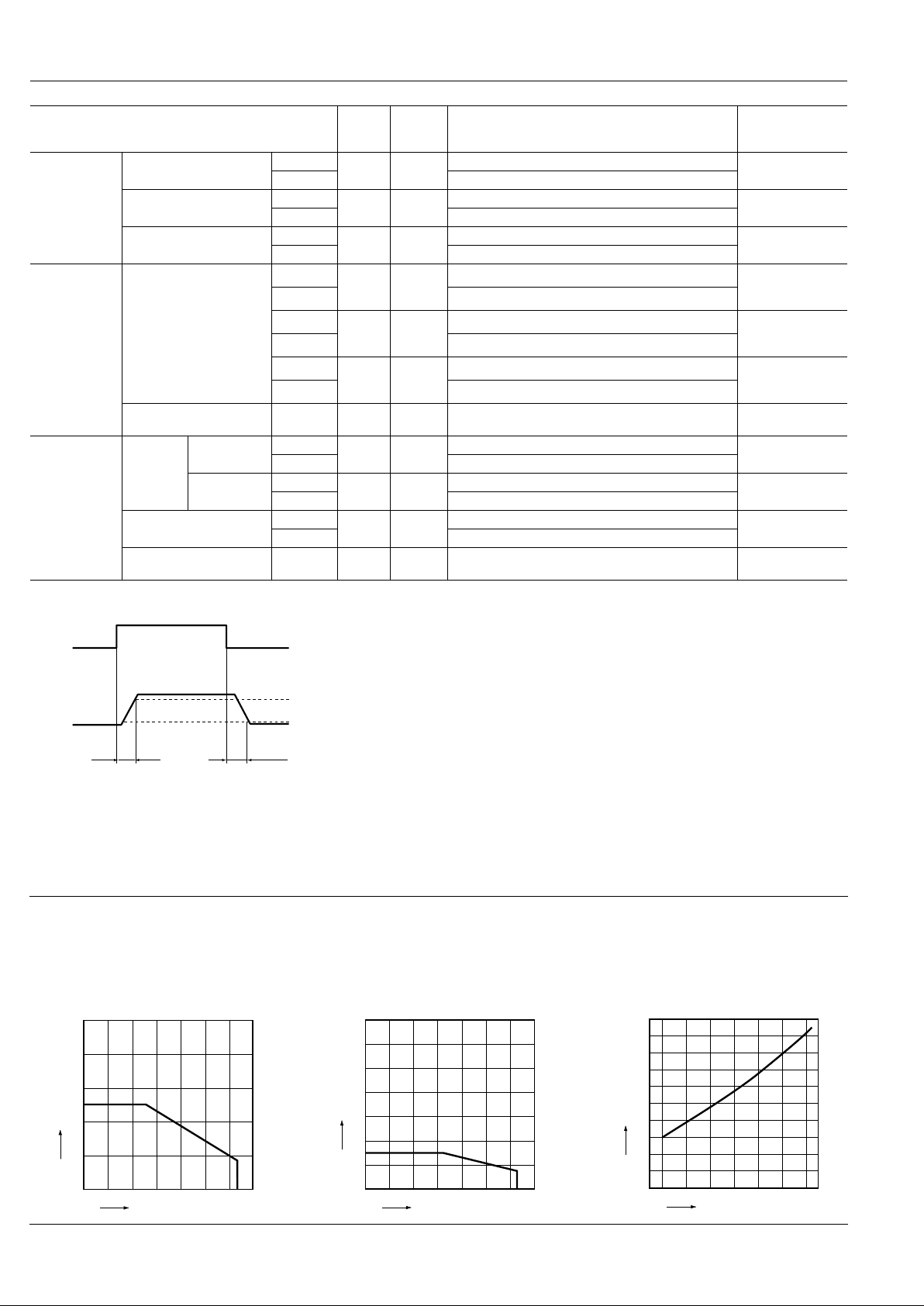
REFERENCE DATA
1. Input current vs. ambient temperature characteristics
Allowable ambient temperature: –40 ° C to +85 ° C
–40 ° F to +185 ° F;
Type of connection: A
2. Load current vs. ambient temperature characteristics
Allowable ambient temperature: –40 ° C to +85 ° C
–40 ° F to +185 ° F;
Type of connection: A
3. On resistance vs. ambient temperature characteristics
Measured portion: between terminals 4 and 6;
LED current: 5 mA;
Load voltage: 400 V (DC);
Continuous load current: 150 mA (DC)
50
40
30
20
10
0
0–40 –20 20 40 60 8085100
Ambient temperautre, °C
Input current, mA
0.7
0.6
0.5
0.4
0.3
0.2
0.1
0
0–40 20 40 60 8085 100
–20
Ambient temperautre, °C
Load curret, A
20
18
16
14
12
10
8
6
4
2
0
0–40 20 40 60 8085
–20
Ambient temperature, °C
On resistance, Ω
 Loading...