

NAIS ALZ12F48, ALZ12F24, ALZ12F18, ALZ12F12, ALZ12F09 Datasheet
...
VDE
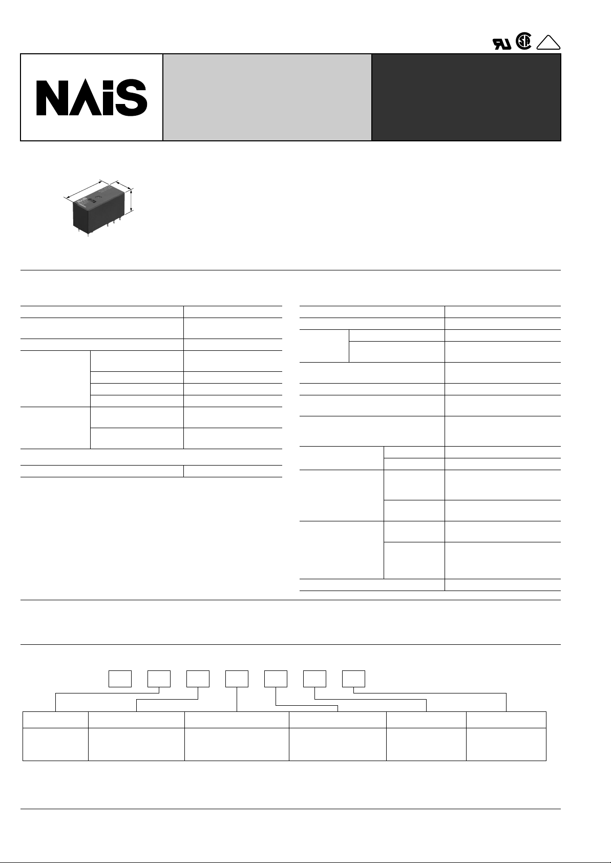
16A Low Profile Power Relay
FEATURES
28.8
1.134
12.5
.492
15.7
.618
1. Low profile size: Height 15.7 mm
28.8 (L)×12.5 (W)×15.7(H) mm 1.134
(L)×.492 (W)×.618(H) inch
2. High insulation resistance
Creepage distance and clearances
between contact and coil: Min. 10 mm
3. UL coil insulation class B (85°C
185°F) or class F (105°C 221°F).
SPECIFICATIONS
Contact
Arrangement 1 Form A, 1 Form C
Initial contact resistance, max.
(By voltage drop 6 V DC 1 A)
Contact material Silver alloy
Nominal switching
capacity
Rating
(resistive load)
Max. switching power 4,000 V A
Max. switching voltage 440 V AC
Max. switching current 16 A
Mechanical
Expected life
(min. operations)
(at 180 cpm)
Electrical (at 20 cpm)*10
(Resistive load)
Coil
Nominal operating power 400 mW
Remarks
* Specifications will vary with foreign standards certification ratings.
*1Measurement at same location as “Initial breakdown voltage” section.
2
Detection current: 10mA
*
3
*
Wave is standard shock voltage of ±1.2 × 50µs according to JEC-212-1981
4
Excluding contact bounce time.
*
*5Half-wave pulse of sine wave: 0.8 ms; detection time: 10 µs
6
Half-wave pulse of sine wave: 6 ms
*
*7Detection time: 10 µs
*8Refer to 5. Conditions for operation, transport and storage mentioned in
AMBIENT ENVIRONMENT (Page 24).
9
Class F type is ambient temperature 105°C 221°F.
*
10
Electrical life was evaluated with the breathing hole open.
*
100 m
Ω
16 A 250 V AC
7
1 × 10
N.O.: 105
N.C.: 5 × 10
4
LZ RELAYS
4. Pb free and Cd free
5. Low operating power
• Nominal operating power: 400mW
6. Conforms to the various safety
standards:
• UL/CSA, VDE approved.
Characteristics
Max. operating speed (at rated load) 20 cpm
Initial insulation resistance*
Initial
breakdown
voltage*
Initial surge voltage between contact
and coil*
Between open contacts 1,000 Vrms for 1 min.
Between contacts and
2
coil
3
Operate time*4 (at nominal voltage) Max. 15ms (at 20°C 68°F)
Release time (with diode)*4
(at nominal voltage)
Temperature rise (at nominal voltage)
Shock resistance
Vibration resistance
Conditions for
operation, transport
and storage*
8
(Not freezing and
condensing at low
temperature)
Unit weight Approx. 12 g .42 oz
1
Min. 1,000 MΩ (at 500 V DC)
5,000 Vrms for 1 min.
Min. 10,000 V
Max. 5ms (at 20°C 68°F)
Max. 55°C
(resistance method, contact
current 16 A, 20°C 68°F)
Functional*
Destructive*
Functional*
5
6
7
Min. 100 m/s2{10 G}
Min. 1,000 m/s2{100 G}
10 to 55Hz
at double amplitude of
1.5mm (NO), 0.82mm (NC)
Destructive
Ambient temp.
at double amplitude of 1.5mm
–40°F to +185°F (Class B)*
10 to 55Hz
–40°C to +85°C
Humidity 5 to 85% R.H.
9
TYPICAL APPLICATIONS
• HVAC • Oven ranges • Refrigerators
ORDERING INFORMATION
AEx. LZ 1 2 B 12 W
Product name Contact arrangement Protective construction Coil insulation class Coil voltage, V DC
LZ 1: 1 Form C
2: 1 Form A
UL/CSA approved type is standard.
Notes: 1. Tube packing: Inner carton: 20pcs.; Case: 800pcs.
2. Carton packing: Inner carton: 100pcs.; Case: 500pcs.
3. Carton packing symbol “W” is not marked on the relay.
62
1: Flux-resistant type
2: Sealed type
B:F:Class B insulation
Class F insulation
05: 5 18: 18
09: 9 24: 24
12: 12 48: 48
Packing style
Nil: Tube packing
W: Carton packing
TYPES
Coil
Coil
Contact arrangement Coil voltage, V DC
5 ALZ21B05 ALZ21F05 ALZ22B05 ALZ22F05
9 ALZ21B09 ALZ21F09 ALZ22B09 ALZ22F09
1 Form A
12 ALZ21B12 ALZ21F12 ALZ22B12 ALZ22F12
18 ALZ21B18 ALZ21F18 ALZ22B18 ALZ22F18
24 ALZ21B24 ALZ21F24 ALZ22B24 ALZ22F24
48 ALZ21B48 ALZ21F48 ALZ22B48 ALZ22F48
5 ALZ11B05 ALZ11F05 ALZ12B05 ALZ12F05
9 ALZ11B09 ALZ11F09 ALZ12B09 ALZ12F09
1 Form C
12 ALZ11B12 ALZ11F12 ALZ12B12 ALZ12F12
18 ALZ11B18 ALZ11F18 ALZ12B18 ALZ12F18
24 ALZ11B24 ALZ11F24 ALZ12B24 ALZ12F24
48 ALZ11B48 ALZ11F48 ALZ12B48 ALZ12F48
Flux-resistant type Sealed type
Class B Class F Class B Class F
COIL DATA
Nominal voltage,
V DC
5 3.5 0.5 63 80
9 6.3 0.9 203 44.4 11.7
12 8.4 1.2 360 33.3 15.6
18 12.6 1.8 810 22.2 23.4
24 16.8 2.4 1,440 16.7 31.2
48 33.6 4.8 5,760 8.3 62.4
Pick-up voltage,
V DC (max.)
Drop-out voltage,
V DC (min.)
Coil resistance,
Ω (±
10%)
Nominal operating
current, mA (±10%)
Nominal operating
power, W
0.4
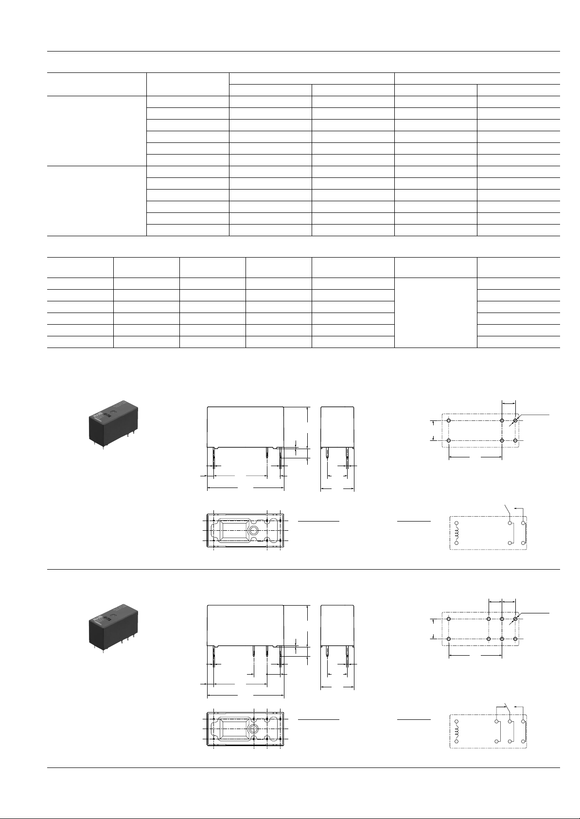
DIMENSIONS
1. 1 Form A type
0.5
.020
15.7
.618
PC board pattern (Copper-side view)
7.5
.295
LZ
Maximum allowable
voltage, V DC
6.5
mm inch
5
.197
6-1.3 dia.
6-.051 dia.
2. 1 Form C type
.098
.098
2.5
2.5
0.5
.020
0.5
.020
20
.787
1.134
20
.787
1.134
28.8
28.8
.197
20
.787
Tolerance : ±0.1 ±.004
Schematic (Bottom view)
.197
0.5
3.5
.020
5
.138
Dimension :
Max. 1mm .039 inch:
7.5
.295
12.5
.492
0.8
.031
Tolerance
±
0.1 ±.004
1 to 3mm .039 to .118 inch:±0.2 ±.008
Min. 3mm .118 inch:
±
0.3 ±.012
PC board pattern (Copper-side view)
5
.1975.197
15.7
.618
0.5
.020
0.5
.020
5
3.5
.138
7.5
.295
12.5
.492
0.8
.031
7.5
.295
20
.787
Tolerance : ±0.1 ±.004
Schematic (Bottom view)
8-1.3 dia.
8-.051 dia.
Dimension : Tolerance
Max. 1mm .039 inch:
±
0.1 ±.004
1 to 3mm .039 to .118 inch:±0.2 ±.008
Min. 3mm .118 inch:
±
0.3 ±.012
63
 Loading...