

NAIS ALF1T24, ALF1P05, ALF1T18, ALF1T12, ALF1T09 Datasheet
...
Product NameLFContact arrangement Terminal shape Coil voltage, V DC
1: 1 Form A
Note: Standard packing; Carton: 50 pcs. Case 200 pcs.
UL/CSA,VDE, TÜV approved type is standard.
T: TMP type
P: PCB type
05: 5 12: 12
06: 6 18: 18
09: 9 24: 24
Ex. A LF 1 T 12
LF
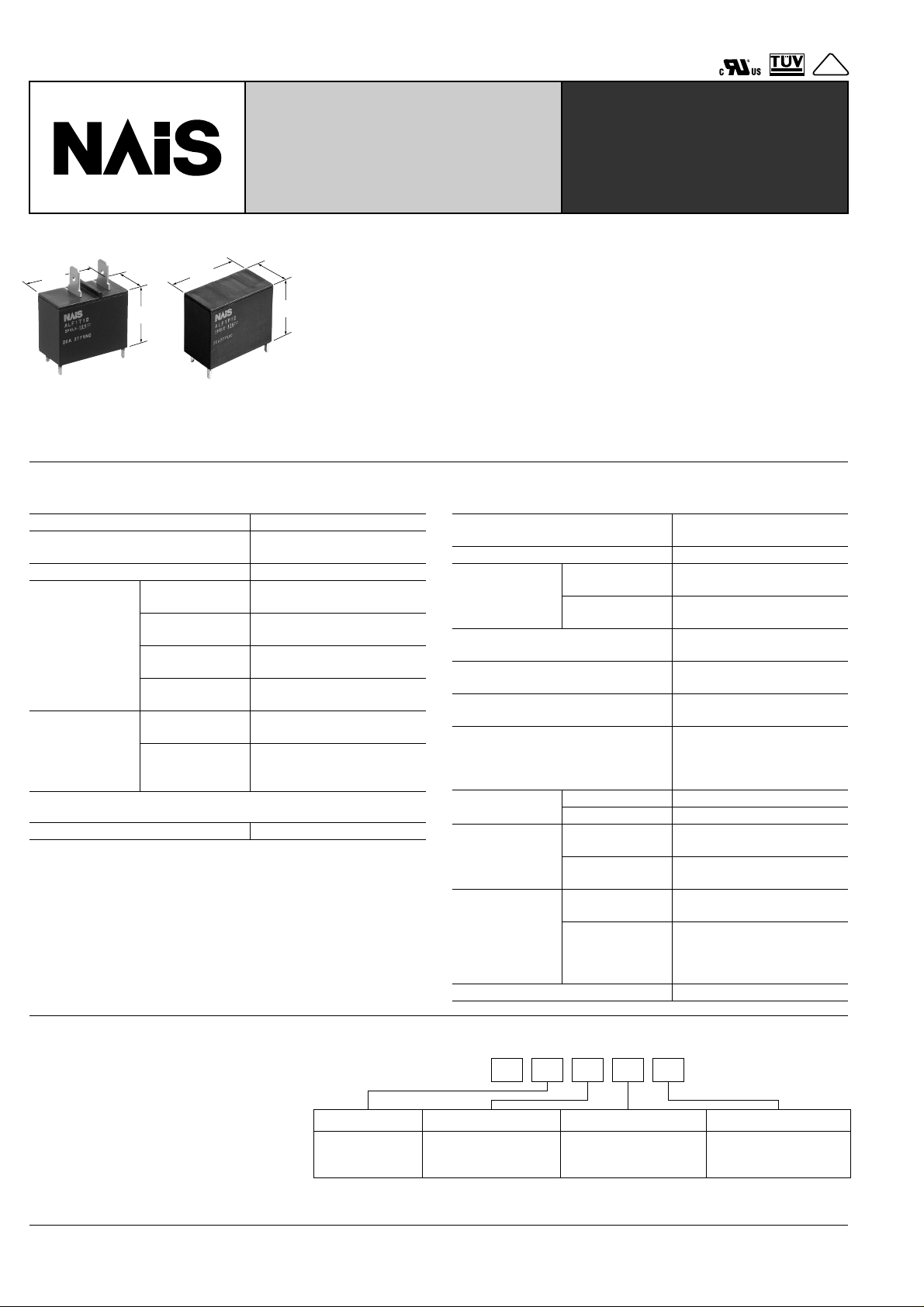
20A Power Relay For
Home appliances
FEATURES
15.7
1. Ideal for compressor and inverter
30.1
1.185
15.7
.618
23.3
.917
30.1
1.185
TMP type PCB type
SPECIFICATIONS
Contact
Arrangement 1 Form A
Initial contact resistance, max.
(By voltage drop 6 V DC 1 A)
Contact material Silver alloy
Nominal switching
capacity
Max. switching
Rating
(resistive load)
Expected life
(min. operations)
Coil
Nominal operating power 900 mW
Remarks
* Specifications will vary with foreign standards certification ratings.
1
Measurement at same location as "Initial breakdown voltage" section.
*
2
Detection current: 10mA
*
3
Wave is standard shock voltage of ± 1.2 × 50 µ s according to JEC-212-1981
*
4
Excluding contact bounce time.
*
5
Half-wave pulse of sine wave: 11 ms; detection time: 10 µ s
*
6
Half-wave pulse of sine wave: 6 ms
*
7
Detection time: 10 µ s
*
8
*
Refer to 5. Conditions for operation, transport and storage mentioned in
AMBIENT ENVIRONMENT (Page 24).
power
Max. switching
voltage
Max. switching
current
Mechanical
(at 180 cpm)
Electrical
(at 20 cpm)
(Resistive load)
.618
23.3
.917
mm inch
loads
1) Compressor load: 20A 250V AC
2)
Inverter load: 20A 100V A C, 10A 200V AC
2. High insulation resistance
• Creepage distance and clearances
between contact and coil;
Creepage Min. 9.5mm .374inch/Clearance Min. 8mm .315inch
• Surge withstand voltage: Min. 10,000V
3. "PCB" and "TMP" types available
100 m Ω
20 A 250V AC
6,250 V A
250V AC
25 A
6
2 × 10
5
10
LF-RELAYS
4. Conforms to the various safety
standards:
UL/CSA, TÜV, VDE approved
Characteristics
Max. operating speed
(at rated load)
Initial insulation resistance*
1
Min. 1,000 M Ω (at 500 V DC)
Between open
Initial breakdown
2
voltage*
contacts
Between contacts
and coil
Surge voltage between contact and
3
coil*
Operate time*
4
(at nominal voltage)
Release time (without diode)*
4
(at nominal voltage)
Temperature rise
(resistance method, contact
(at nominal voltage)
Shock
resistance
Vibration
resistance
Conditions for
operation, transport and storage*
(Not freezing and
condensing at low
Functional*
Destructive*
Functional*
Destructive
Ambient temp.
8
Humidity 5 to 85% R.H.
5
6
7
at double amplitude of 1.5mm
at double amplitude of 1.5mm
temperature)
Unit weight Approx. 23 g .81 oz
20 cpm
1,000 Vrms for 1 min.
5,000 Vrms for 1 min.
Min. 10,000 V
Approx. 15ms
Approx. 15ms
Max. 45 ° C
current 20 A, rated coil
voltage, 60 ° C 140 ° F)
Min. 100 m/s
Min. 1,000 m/s
2
{10 G}
2
{100 G}
10 to 55Hz
10 to 55Hz
–40 ° C to +60 ° C
–40 ° F to +140 ° F
VDE
TYPICAL
ORDERING INFORMATION
APPLICATIONS
• Air conditioner
• Refrigerators
• OA equipment
40
TYPES
4-1.8 dia.
4-.071 dia.
±.004
1.087
±0.1
27.6
±0.1
13.8
±.004
.543
±0.1
12.0
±0.1
10.0
±.004
.472
±.004
.394
±0.1
12.0
±.004
.472
±.004
1.087
±0.1
27.6
±0.1
13.8
±.004
.543
±0.1
12.0
±0.1
10.0
±.004
.472
±.004
.394
±0.1
12.0
±.004
.472
4-1.8 dia.
4-.071 dia.
Contact
arrangement
1 Form A
COIL DATA
Nominal voltage,
V DC
5 3.5 0.5 27.8 180
6 4.2 0.6 40 150 6.6
9 6.3 0.9 90 100 9.9
12 8.4 1.2 160 75 13.2
18 12.6 1.8 360 50 19.8
24 16.8 2.4 640 37.5 26.4
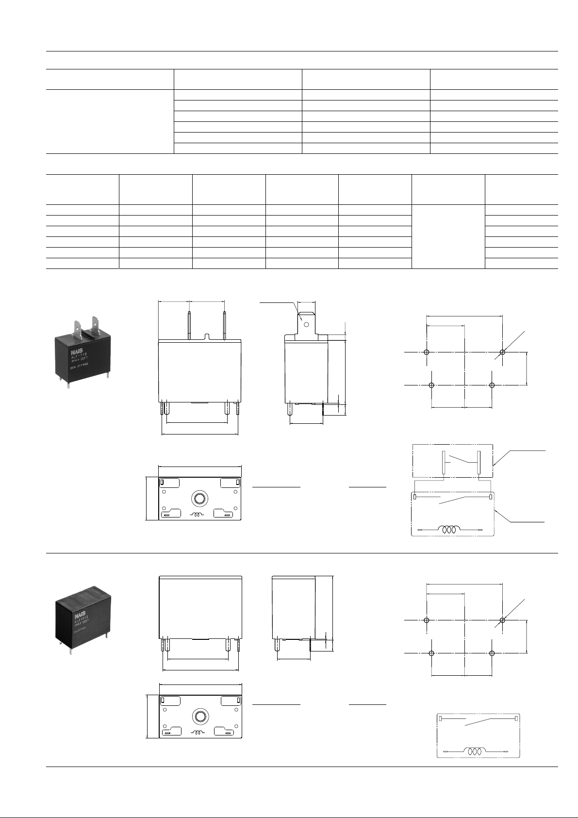
DIMENSIONS
1. TMP type
Pick-up voltage,
V DC (max.)
11.25
.443
Ω ( ±
Coil voltage,
V DC
5 ALF1T05 ALF1P05
6 ALF1T06 ALF1P06
9 ALF1T09 ALF1P09
12 ALF1T12 ALF1P12
18 ALF1T18 ALF1P18
24 ALF1T24 ALF1P24
Drop-out voltage,
V DC (min.)
12.8
.504
±
Coil resistance,
#250 terminal
±
±
±
LF
TMP type PCB type
10%)
6.4
.252
Nominal operating
current, mA
( ± 10%)
2.0
.079
Nominal operating
power, W
Maximum allow-
able voltage, V DC
5.5
0.9
mm inch
PC board pattern (Bottom view)
2. PCB type
15.7
.618
15.7
.618
23.3
.917
0.5
.020
4.0
22.0
.866
27.6
1.087
30.1
1.185
3 NO COM 4
12
12.0
.472
Dimension :
Tolerance
Max. 1mm .039 inch:
1 to 3mm .039 to .118 inch: ± 0.2 ± .008
Min. 3mm .118 inch:
.157
0.1 ± .004
0.3 ± .012
Tolerance : ± 0.1 ± .004
Schematic (Bottom view)
FASTON 250
NO COM
PC board side
PC board pattern (Bottom view)
23.3
.917
0.5
.020
4.0
22.0
.866
27.6
1.087
30.1
1.185
3 NO COM 4
Dimension :
12.0
.472
Tolerance
Max. 1mm .039 inch:
1 to 3mm .039 to .118 inch: ± 0.2 ± .008
12
Min. 3mm .118 inch:
.157
0.1 ± .004
0.3 ± .012
Tolerance : ± 0.1 ± .004
Schematic (Bottom view)
NO COM
41
 Loading...