

Page 1

WORLD CLASS HI FI
CONNECTION GUIDE
Equipment Connection Panels and System Connection Schematics
ISSUE 1
Page 2

1
Introduction
This connection guide, available only in Adobe PDF format, collects together
illustrations of product connection panels and many of the most often used system
connection diagrams. Most illustrations and diagrams can also be found in the
appropriate product Owners Manual. This guide should not be seen as a replacement
for specific Owners Manuals as these contain important safety and installation
information as well as comprehesive installation and operation guidance
CONTENTS
Section Page
1 2 CD Players
1.1 CDS3
1.2 CDX2
1.3 CD5
3 1.4 CDS3/XPS2
1.5 CDX2/XPS2
4 1.6 CD5/Flatcap 2
2 5 Tuner
2.1 NAT 05
3 6 Headphone Amplifier
3.1 Headline
3.2 Headline/Hi-Cap
4 7 Phono Stage
4.1 Stageline
4.2 Stageline/NAC 112
4.3 Stageline/Flatcap 2
5 8 Preamplifiers
5.1 NAC 552
5.2 NAC 252
9 5.3 NAC 282
5.4 NAC 202
10 5.5 NAC 112
11 5.6 NAC 552/NAC 552PS
5.7 NAC 252/Supercap
12 5.8 NAC 282/Supercap
5.9 NAC 282/Hi-Cap
13 5.10 NAC 202/Hi-Cap
5.11 NAC 112/Flatcap 2
6 14 AV Processor
6.1 AV2
15 6.2 AV2/NAP 150/
NAP V175
16 6.3 AV2/NAC 112/
NAP 150/NAP V175
7 17 Integrated Amplifier
7.1 NAIT 5
7.2 NAIT 5/Flatcap 2
18 7.3 NAIT 5/NAP 150
7.4 NAIT 5/Flatcap 2/
NAP 150
Section Page
8 19 Power Amplifiers
8.1 NAP 500
20 8.2 NAP 300
8.3 NAP 250
21 8.4 NAP V145
8.5 NAP 200
8.6 NAP 150
22 8.7 NAP 6-50
8.8 NAP V175
9 23 Power Supplies
9.1 XPS2
9.2 Supercap
9.3 Hi-Cap
24 9.4 Flatcap 2
9.5 NAPSC
25 9.6 NAC 252/Supercap/
Hi-Cap
26 9.7 NAC 282/NAPSC/
Supercap x 2
27 9.8 NAC 282/NAPSC/Hi-Cap
9.9 NAC 282/NAPSC/
Hi-Cap x 2
28 9.10 NAC 202/Hi-Cap/
NAPSC
9.11 NAC 112/Flatcap x 2
10 29 Active Crossovers
10.1 SNAXO 362
10.2 SNAXO 242
10.3 SNAXO 362/Supercap
30 10.4 SNAXO 242/Hi-Cap
31 10.5 SNAXO 362/
NAP 300 x 3
32 10.6 SNAXO 362/
NAP 250 x 3
33 10.7 SNAXO 242/
NAP 250 x 2
Page 3
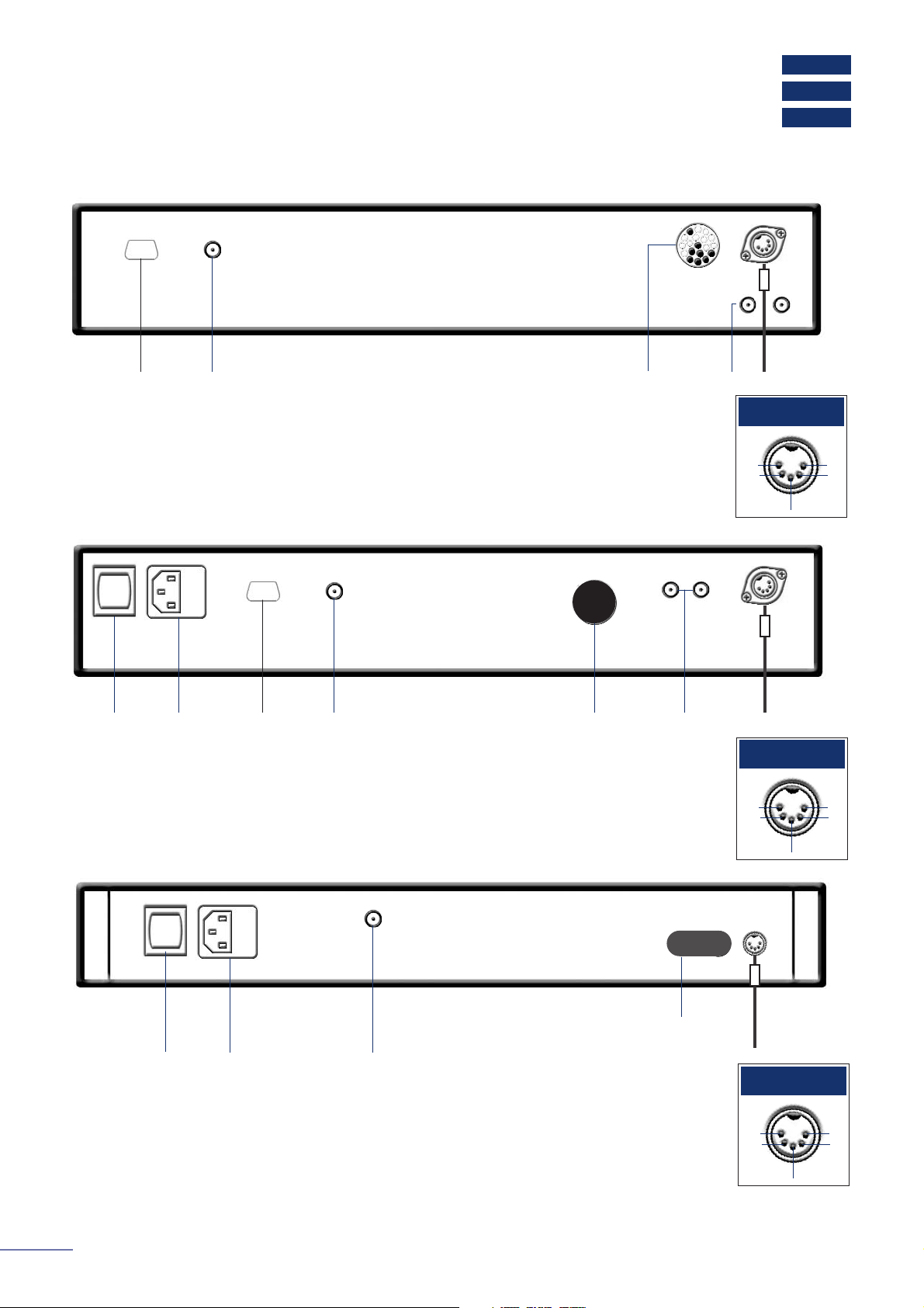
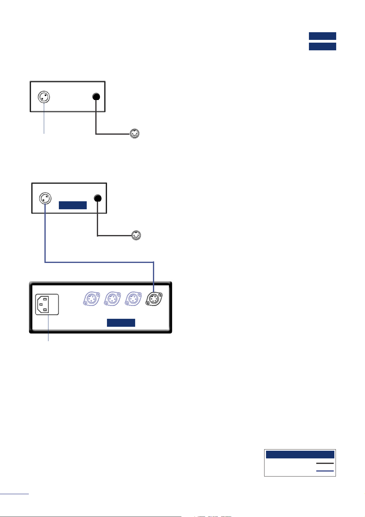
CD5
CDX2
CDS3
CD Players
to preamplifier
XPS2 power supply connection socket
ch1
out
-ve
nc
nc
ch 2
out
CDS3 Output
1.1 CDS3 Connection Panel
alternative
RCA phono
output sockets
RC5 input
Note
The RC5 input fitted to the CDS3 is intended to accept external control signals for multi-
room applications. Contact your dealer for further information on its use.
optional
RS232
data port
to preamplifier
mains
input
power
link plug fitted
ch1
out
-ve
nc
nc
ch 2
out
CDX2 Output
1.2 CDX2 Connection Panel
alternative
RCA phono
output sockets
RC5 input
Note
The RC5 input fitted to the CDX2 is intended to accept external control signals for multi-
room applications. Contact your dealer for further information on its use.
optional
RS232
data port
ch1
out
-ve
nc
nc
ch 2
out
CD5 Output
1.3 CD5 Connection Panel
to preamplifier
mains inputpower
link plug fitted
RC5 input
Note
The RC5 input fitted to the CD5 is intended to accept external control signals for multi-room
applications. Contact your dealer for further information on its use.
The CD5 features various technologies to reduce microphonic effects, in particular a
compliant mounting for the main circuit boards and the DIN sockets on the rear. Some
movement of the board and sockets when connecting/disconnecting is normal.
2
Page 4
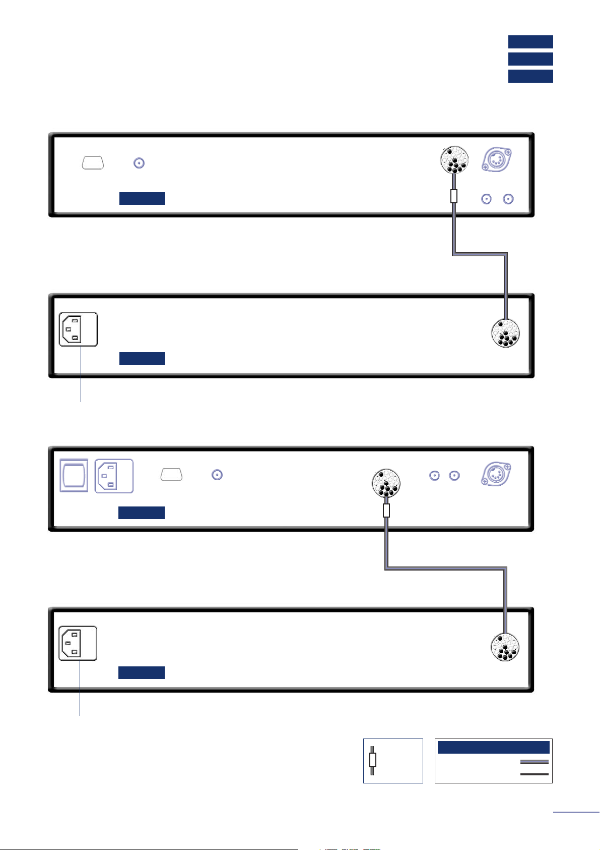
XPS2
CDX2
CDS3
CD Players
mains input
CDS3/XPS2 Burndy
180° 5 to 5 pin DIN
Interconnect Cables
cable
direction
marker
1.4 CDS3 Connected to XPS2 Power Supply
XPS2
CDS3
mains input
Note
When used with an XPS2 the CDX2 must be disconnected
from the mains. Always switch off the CDX2 when
connecting or disconnecting an XPS2.
1.5 CDX2 Connected to XPS2 Power Supply
XPS2
CDX2
3
Page 5
Flatcap 2
CD5
1.6 CD5 Connected to Flatcap 2 Power Supply
mains input
link plug removed
mains inputpower
Flatcap 2
CD5
cable
direction
marker
240° 5 to 5 pin DIN
Interconnect Cables
CD Players
4
power
Page 6
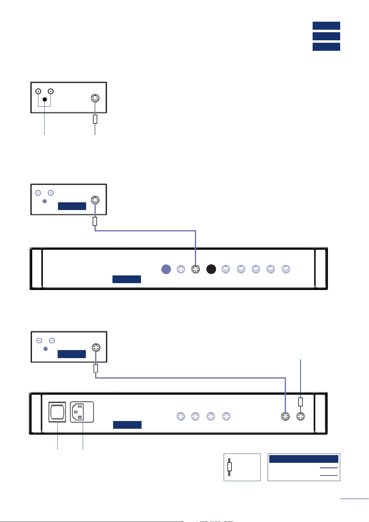
NAT 05
Tuners
2.1 NAT 05 Connection Panel
to preamplifier
mains input
power
Note
The RC5 input fitted to the NAT 05 is intended to accept external control signals for multi-
room applications. Contact your dealer for further information on its use.
The NAT 05 features various technologies to reduce microphonic effects, in particular a
compliant mounting for the main circuit boards and the DIN sockets on the rear. Some
movement of the board and sockets when connecting/disconnecting is normal.
75 ohm FM aerialRC5 input
ch1
out
-ve
nc
nc
ch 2
out
NAT 05 Output
5
cable
direction
marker
180° 5 to 5 pin DIN
Interconnect Cables
Page 7
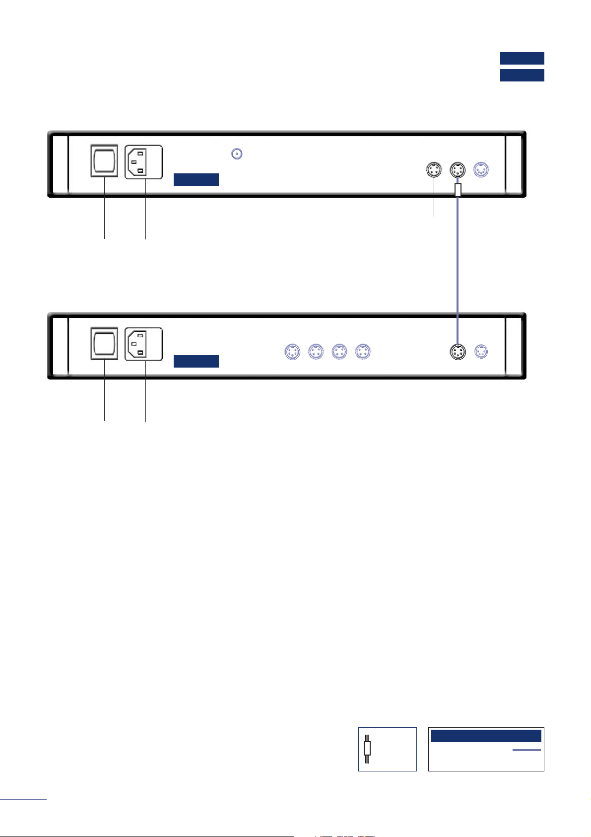
6
Hi-Cap
Headline
3.1 Headline Connection Panel
3.2 Headline connected to Hi-Cap power supply
Headphone Amplifier
flying signal cable
mains input
Hi-Cap
from power
supply (NAPSC)
or better)
Connect to:
NAC 552, NAC 252,
NAC 282, NAC 202:
Socket 4, 5 or 6.
NAC 112, NAIT 5:
Socket 3, 4 or 5.
Headline
Captive 180° 5 pin DIN
5 pin DIN - 2 pin (SLIC)
Interconnect Cables
Page 8
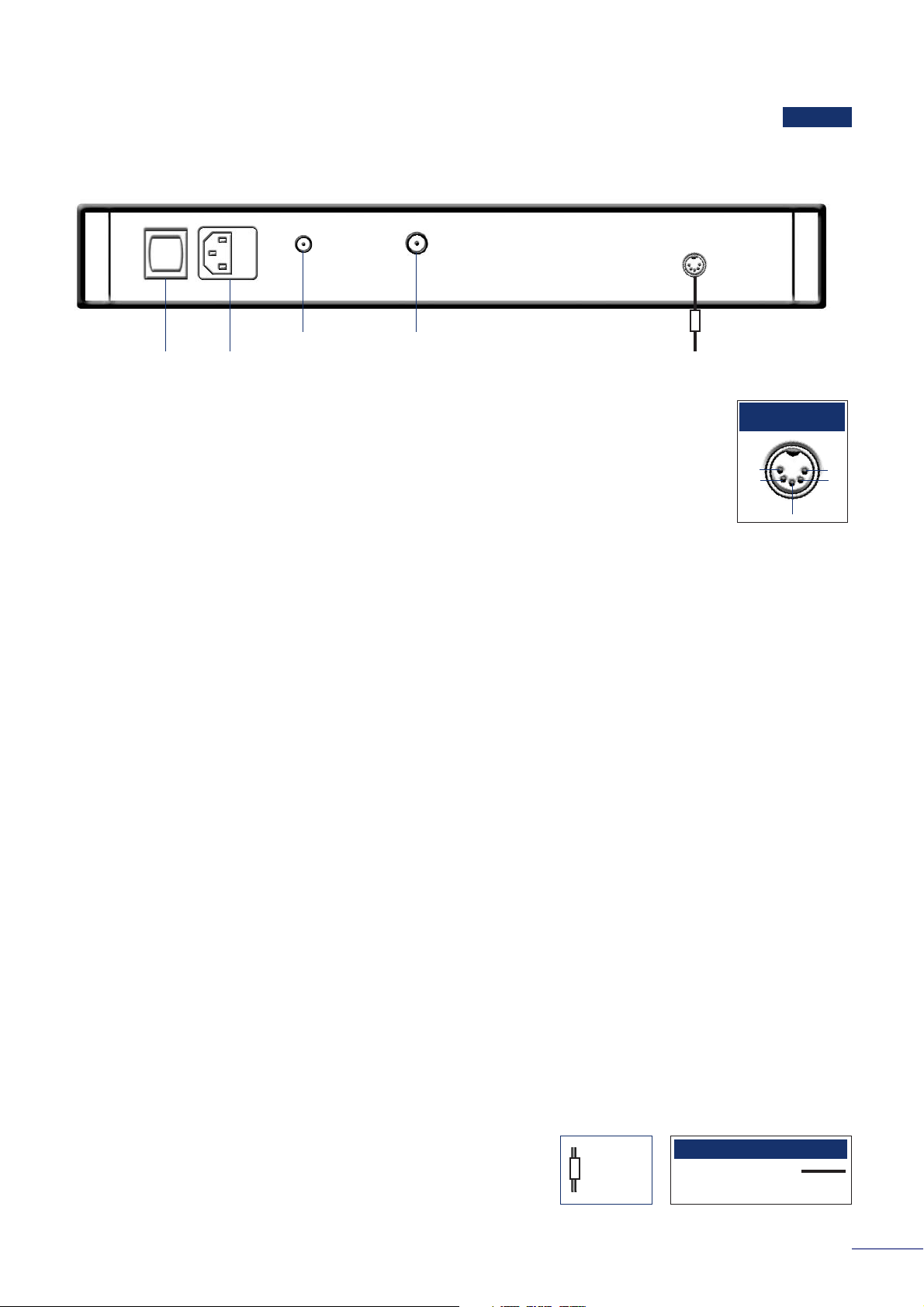
7
Flatcap 2
NAC 112
Stageline
4.1 Stageline Connection Panel
Phono Stage
RCA phono
sockets and
earth tag
to preamplifier power
supply or NAC 112/NAIT 5
AUX 2b socket
to preamplifier. 4 to 5 pin
DIN interconnect required
4.2 Stageline connected to NAC 112 (or NAIT 5)
4.3 Stageline connected to Flatcap 2
cable
direction
marker
240° 5 to 5 pin DIN
4 to 5 pin DIN
Interconnect Cables
power
Flatcap 2
NAC 112
Stageline
Stageline
mains input
Page 9
8
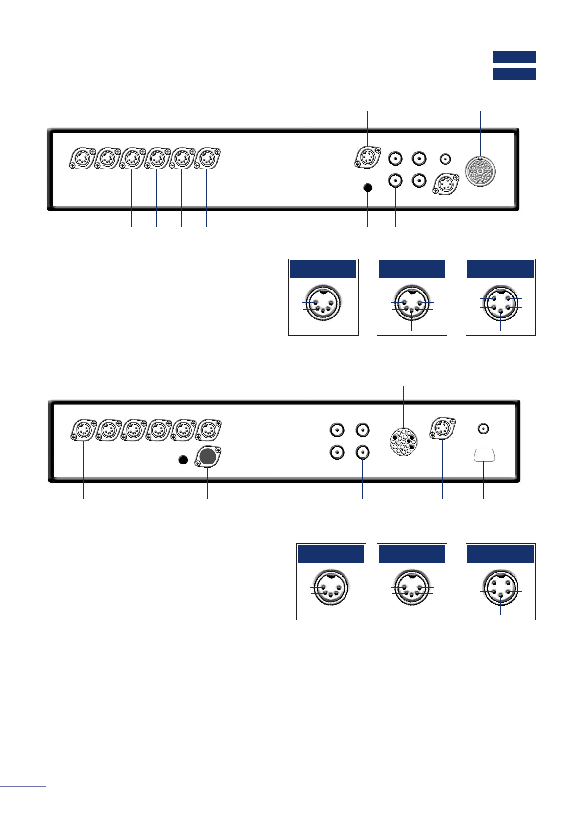
NAC 252
NAC 552
Preamplifiers
5.1 NAC 552 Connection Panel
5.2 NAC 252 Connection Panel
in 1 in 2 in 3 in 4 in 5 in 6
in 8
ch 1
ch 2
signal ground in 9
ch 1
ch 2
NAC 552PS in
in 7 rc5 control in NAC 552PS in
ch1
in
-ve
ch 2
in
Inputs 1, 2 & 3
ch1
in
ch1
out
ch2
out
-ve
ch 2
in
Inputs 4, 5 & 6
+ve
+ve
ch1
-ve
ch 2
Input 7
in 1
cd
in 2
tuner
in 3
tape
in 4
a/v
in 5
aux 1
in 6
aux 2
cd
phono
ch 1
ch 2
signal
ground
aux 2
phono
ch 1
ch 2
Supercap
in
rc5 control inSupercap in
ch1
in
-ve
ch 2
in
Inputs 1, 2 & 6
ch1
in
ch1
out
ch2
out
-ve
ch 2
in
Inputs 3, 4 & 5
+ve
+ve
ch1
-ve
ch 2
Input 6
(alternative)
in 6 (alternative)
optional
RS232 data
port
Note
The NAC 252 AUX 2 input is provided with two sockets. The
lower socket, fitted on delivery with a blanking cover, is
intended for use with a Stageline or Prefix phono stage and
incorporates an appropriate DC power supply. The two
sockets must not be used simultaneously.
Page 10

9
NAC 202
NAC 282
5.4 NAC 202 Connection Panel
Preamplifiers
5.3 NAC 282 Connection Panel
in 1
cd
in 2
tuner
in 3
tape
in 4
a/v
in 5 aux 1
in 6 aux 2
cd
phono
ch 1
ch 2
signal
ground
aux 2
phono
ch 1
ch 2
rc5 control in
to NAPSC
Power supply/output
option sockets with
link and blanking
plugs fitted
in 6 (alternative)
to power
amplifier with
preamplifier
power supply
Note
The NAC 282 AUX 2 input is provided with two sockets. The
lower socket, fitted on delivery with a blanking cover, is
intended for use with a Stageline or Prefix phono stage and
incorporates an appropriate DC power supply. The two
sockets must not be used simultaneously.
optional
RS232 data
port
ch1
in
-ve
ch 2
in
Inputs 1, 2 & 6
ch1
in
ch1
out
ch2
out
-ve
ch 2
in
Inputs 3, 4 & 5
+ve
+ve
ch1
-ve
ch 2
Input 6
(alternative)
in 1
cd
in 2
tuner
in 3
tape
in 4
a/v
signal
ground
in 6
(alternative)
cd
phono
ch 1
ch 2
in 5
aux 1
aux 2
phono
ch 1
ch 2
rc5 control in
to NAPSC
(optional)
Power supply/output
option sockets with
link and blanking
plugs fitted
ch1
in
-ve
ch 2
in
Inputs 1, 2 & 6
ch1
in
ch1
out
ch2
out
-ve
ch 2
in
Inputs 3, 4 & 5
+ve
+ve
ch1
-ve
ch 2
Input 6
(alternative)
in 6
aux 2
to power
amplifier with
preamplifier
power supply
Note
The NAC 202 AUX 2 input is provided with two sockets. The
upper socket, fitted on delivery with a blanking cover, is
intended for use with a Stageline or Prefix phono stage or a
Headline headphone amplifier and incorporates an
appropriate DC power supply. The two sockets must not be
used simultaneously.
optional
RS232 data
port
cable
direction
marker
4 to 4 pin DIN
Interconnect Cables
Page 11
10
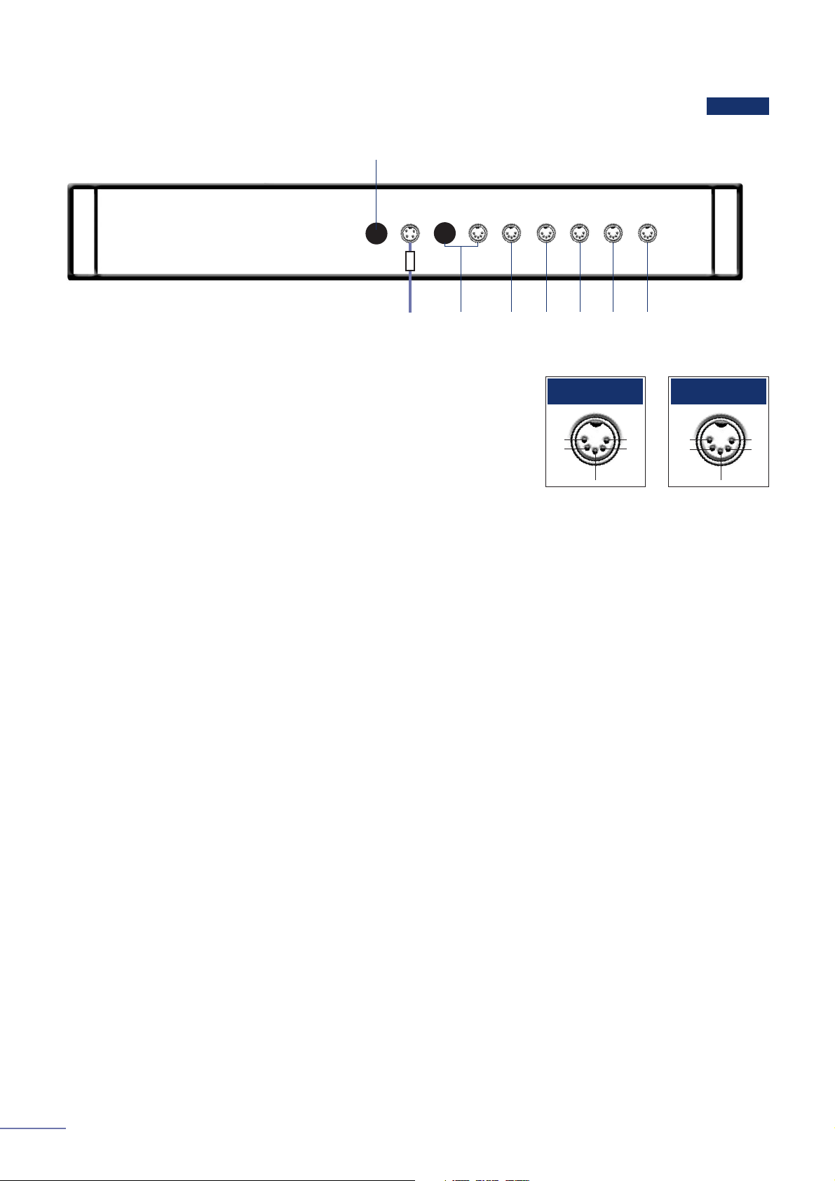
NAC 112
Preamplifiers
ch1
in
ch1
out
ch2
out
-ve
ch2
in
ch1
in
ch2
in
TAPE, AV & AUX 1
Inputs
nc
nc
-ve
CD, TUNER &
AUX 2 Inputs
Note
The NAC 112 AUX 2 input is provided with two sockets. The
left hand socket, fitted on delivery with a blanking cover, is
intended for use with a Stageline or Prefix phono stage or a
Headline headphone amplifier and incorporates an
appropriate DC power supply. The two sockets must not be
used simultaneously.
cd tuner tape av
aux 1 aux 2
to stereo power amplifier with
preamplifier power supply output
power supply/output option socket with link and blanking plug fitted
5.5 NAC 112 Connection Panel
Page 12

11
NAC 252
Supercap
NAC 552PS
NAC 552
Preamplifiers
5.6 NAC 552 connection to NAC 552PS power supply
NAC 552 Burndy
NAC 252 Burndy
240° 5 to 5 pin DIN
Interconnect Cables
cable
direction
marker
mains in
to stereo power
amplifier
to mono or dual
mono power
amplifiers
additional signal
output
Note
For best performance the Burndy and 5 pin DIN cables
should be run as close together as possible.
Note
For best performance the Burndy and 5 pin DIN cables
should be run as close together as possible.
NAC 552
NAC 552PS
mains input
to stereo power amplifier
to mono or dual mono power amplifiers
additional signal output
Supercap
NAC 252
5.7 NAC 252 connection to Supercap power supply
Page 13

12
Hi-Cap
Supercap
NAC 282
Preamplifiers
5.9 NAC 282 connection to Hi-Cap power supply
cable
direction
marker
mains input
to stereo power amplifier
additional signal output
to mono or dual mono
power amplifiers
to NAPSC
Hi-Cap
NAC 282
240° 5 to 5 pin DIN
Interconnect Cables
5.8 NAC 282 connection to Supercap power supply
to NAPSC
Note
NAC 282 can also be powered by two Hi-Cap supplies. In
this case they are connected to the same sockets as the
two Supercap power supply cables.
Note
See Page 27 for NAC 282 with multiple Hi-Caps.
NAC 282
mains input
additional signal
output
to mono or dual mono
power amplifiers
to stereo
power amplifiers
Supercap
Page 14

Note
NAC 202 may also be powered by Supercap or Flatcap 2
power supplies connected in a similar manner to the Hi-Cap.
13
NAC 112
Flatcap 2
Hi-Cap
NAC 202
cable
direction
marker
240° 5 to 5 pin DIN
Interconnect Cables
Preamplifiers
5.10 NAC 202 connection to Hi-Cap power supply
mains input
to stereo power amplifier
additional signal output
to mono or dual mono power amplifiers
to NAPSC (optional)
Note
The NAPSC socket to 4
pin DIN link plug must
remain in place if no
NAPSC is used.
NAC 202
Hi-Cap
5.11 NAC 112 connected to FLATCAP 2 power supply
power
mains input
for CD5, Headline or
Stageline. Additional
interconnects
required.
to stereo power
amplifier
to mono or dual
mono power
amplifiers
NAC 112
Flatcap 2
Page 15

14
AV2
AV Processor
6.1 AV2 Connection Panel
ch1
in
-ve
ch2
in
Analog in 3
mains
in
power
rear
out
ch1
nc
ch2
-ve
Rear out
cen
nc
sub
-ve
Centre out
ch1
nc
ch2
-ve
Surround out
ch1
nc
ch2
-ve
Front out
centre
(sub)
out
surr’d
out
front
out
sub
out
rc5
in
dig
out
2
dig
in
2
dig
opt
out
dig
opt
in 2
dig
opt
in 1
rec
out
analog
in 6
analog
in 5
analog
in 4
dig
out
1
dig
in
1
data
in/out
rs232
video
switch
in/out
ch1
left
ch2
right
analog
in 3
(sys out)
analog
in 1
(versatile)
analog
in 2
(versatile)
front
out
ch1
ch2
ch1
in
-ve
ch2
in
Analog in VI2
ch1
in
-ve
ch2
in
Analog in VI1
cen
in
-ve
sub
in
Analog in VI2 and VI1 - multiple mode
V2
V1
rear
in
ch1
ch2
-ve
surr’d
in
ch1
ch2
front
in
ch1
ch2
Note
The AV2 features various technologies to reduce
microphonic effects, in particular a compliant mounting for
the main circuit boards and the DIN sockets on the rear.
Some movement of the board and sockets when
connecting/disconnecting is normal.
Page 16

15
NAP 150
NAP V175
AV2
AV Processor
+- -+
+- -+ -+
AV2
NAP V175
NAP 150
to sub-woofer
surround
ch1, left
centre
surround
ch2, right
front
ch1, left
front
ch 2, right
6.2 AV2 connected to NAP V175 and NAP 150
cable
direction
marker
4 to 4 pin DIN
Interconnect Cables
mains
in
power
mains
in
power
mains
in
power
+- -+
NAP 150
rear effects
ch1, left
rear effects
ch 2, right
mains
in
power
With extra NAP 150 for 7.1 applications
Page 17

16
NAP 150
NAP V175
NAC 112
AV2
AV Processor
6.3 AV2 connected to NAC 112, NAP 150 and NAP V175
cable
direction
marker
4 to 4 pin DIN
180° 5 to 5 pin DIN
(AV2/NAC 112 special)
Interconnect Cables
link plug and cover fitted
AV2
NAP V175
NAP 150
NAC 112
to sub-woofer
surround
ch1, left
centre
surround
ch2, right
front
ch1, left
front
ch 2, right
+- -+ -+
+- -+
mains
in
power
mains
in
power
mains
in
power
Page 18

17
Flatcap 2
NAIT 5
Integrated Amplifier
7.1 NAIT 5 Connection Panel
cable
direction
marker
4 to 4 pin DIN
240° 5 to 5 pin DIN
Interconnect Cables
ch1
in
ch1
out
ch2
out
-ve
ch2
in
Tape, A/V, AUX 1,
inputs
ch1
nc
nc
-ve
ch2
CD, Tuner & Aux
2 inputs
+V in
+V in
ch1
-ve
ch2
Signal out A
mains input
power
to left
loudspeaker ch1
to right
loudspeaker ch2
input
signal
out A
signal
out B
aux 2 aux 1 av tape tuner cd
link plugs fitted
+- -+
mains
input
power
link plug fitted
+- -+
7.2 NAIT 5 connected to Flatcap 2 power supply
mains
input
power
Flatcap 2
NAIT 5
for CD5, Headline
or Stageline.
Additional
interconnects
required.
Page 19

18
Flatcap 2
NAP 150
NAIT 5
Integrated Amplifier
7.3 NAIT 5 connected to NAP 150 power amplifier
link plug and cover fitted
+- -+
mains
input
speakers
ch1 left
speakers
ch2 right
power
NAP 150
NAIT 5
+- -+
mains
input
speakers
ch1 left
speakers
ch2 right
power
NAP 150
cable
direction
marker
4 to 4 pin DIN
240° 5 to 5 pin DIN
Interconnect Cables
link plug removed, cover fitted
7.4 NAIT 5 connected to Flatcap 2 power supply and NAP 150 power amplifier
mains
input
power
Flatcap 2
NAIT 5
Note
Mains power must not be connected to the NAIT 5 when it
is used as a preamplifier (i.e. powered externally).
Note
Mains power must not be connected to the NAIT 5 when it
is used as a preamplifier (i.e. powered externally).
Page 20

19
NAP 500PS
NAP 500
Power Amplifiers
8.1 NAP 500 and NAP 500PS Connection Panels
-++-
Input Socket 1 Input Socket 2
to
preamplifier
power supply.
Left, ch1.
to preamplifier
power supply.
Right, ch2.
left
speaker ch1
right
speaker ch2
ch1
-ve
-ve
nc
nc
ch 2
mains in
1 2
NAP 500
NAP 500PS
NAP 500 Burndy
Interconnect Cables
cable
direction
marker
Page 21

20
NAP 250
NAP 300PS
NAP 300
Power Amplifiers
8.2 NAP 300 and NAP 300PS Connection Panels
8.3 NAP 250 Connection Panel
mains in
left
speaker ch1
-+
right
speaker ch2
to
preamplifier
power
supply.
Right, ch2.
-+
to
preamplifier
power
supply.
Left, ch1.
1 2
Input Socket 1 Input Socket 2
ch1
-ve
-ve
nc
nc
ch 2
NAP 300
NAP 300PS
ch2
-ve
ch 1
Input socket
mains in
left
speaker ch1
-+
right
speaker ch2
to preamplifier power
supply
-+
NAP 300 Burndy
Interconnect Cables
cable
direction
marker
Page 22

21
NAP 150
NAP 200
NAP V145
Power Amplifiers
8.4 NAP V145 Connection Panel
-ve
i/p
Input socket
mains in
speaker output
to preamplifier
power supply
-+
ch1
-ve
+ve
ch 2
Input socket
ch1
-ve
+ve
ch 2
Input socket
mains in
left
speaker ch1
-+
right
speaker ch2
to preamplifier or
power supply
-+
+- -+
mains
in
power
to preamplifier or
power supply
left
speaker ch1
right
speaker ch2
8.5 NAP 200 Connection Panel
8.6 NAP 150 Connection Panel
Page 23

22
NAP V175
NAP 6-50
Power Amplifiers
8.7 NAP 6-50 Connection Panel
8.8 NAP V175 Connection Panel
mains
input
power
to processor
ch1
nc
ch2
-ve
Input Socket 2
cen
nc
nc
-ve
Input Socket 1
+- -+ -+
1 2
left
speaker
ch1
centre
speaker
right
speaker
ch2
mains input
fan
ventilation inlet
trigger
-+ -+ -+
-+ -+ -+
ch1
chassis
ground
ch2
-ve
Input Sockets
zone 1
speaker
ch1, left
zone 1
speaker
ch2, right
zone 2
speaker
ch2, right
zone 3
speaker
ch2, right
zone 2
speaker
ch1, left
zone 3
speaker
ch1, left
zone 3
zone 1
zone 2
Page 24

23
Hi-Cap
Supercap
XPS2
Power Supplies
9.1 XPS2 Connection Panel
9.2 Supercap Connection Panel
9.3 Hi-Cap Connection Panel
mains input
to CDS3, CDS2,
CDX or CDX2
Note
When used with an XPS2 the CDX2 (or CDX) must be
disconnected from the mains. Always switch off the player
when connecting or disconnecting an XPS2.
ch1
nc
-ve
ch 2
Sockets 3, 4, 5
+ve
ch1
ch2
-ve
+ve
Socket 1
1
2
3 4 5
6
7
Socket 2
+ve
nc
nc
-ve
+ve
Socket 6
NAC 252 only
Socket 7
NAC 252 or
SNAXO only
mains input
mains input
ch1
nc
-ve
ch 2
Sockets 1, 2, 3
+ve
ch1
ch2
-ve
+ve
Socket 4
1 2 3 4
Page 25

24
NAPSC
Flatcap 2
Power Supplies
9.4 Flatcap 2 Connection Panel
9.5 NAPSC Connection Panel
power
1 2 3 4 5 6
ch1
nc
ch 2
-ve
Sockets
2, 3, 4, 6
Sockets 1, 5
+ve
ch1
-ve
+ve
ch2
Note
The Flatcap 2 features various technologies to reduce
microphonic effects, in particular a compliant mounting for the
main circuit boards and the DIN sockets on the rear. Some
movement of the board and sockets when
connecting/disconnecting is normal.
mains input
mains input
output flying
lead
Page 26

25
Hi-Cap
Supercap
NAC 252
Power Supplies
9.6 NAC 252 connection to Supercap power supply
cable
direction
marker
4 to 4 pin DIN
240° 5 to 5 pin DIN
Burndy
Interconnect Cables
Note
Extra Supercap, Hi-cap or Flatcap 2 for SNAXO. Supercap -
socket 5, Hi-cap - socket 3, Flatcap 2 - socket 2.
to SNAXO
mains input
Hi-Cap
Note
For best performance the
Burndy and 5 pin DIN
cables should be run as
close together as
possible.
mains input
to stereo power amplifier
(not in active systems)
to mono or dual mono power
amplifiers (not in active systems)
additional signal output
Supercap
NAC 252
Page 27

26
Supercap
NAPSC
NAC 282
Power Supplies
9.7 NAC 282 connection to NAPSC and Supercap power supply
mains input
NAPSC
With extra Supercap for SNAXO
cable
direction
marker
4 to 4 pin DIN
240° 5 to 5 pin DIN
Interconnect Cables
NAC 282
mains input
to stereo power amplifiers
(not in active systems)
Supercap
mains input to SNAXO
Supercap
to mono or dual mono power
amplifiers (not in active systems)
Page 28

27
NAPSC
Flatcap 2
Hi-Cap
NAC 282
Power Supplies
9.8 NAC 282 connection to Hi-Cap and NAPSC power supplies
9.9 NAC 282 connection to two Hi-Caps (or Flatcap 2s)
mains input
With extra Flatcap 2 (or Hi-cap) for SNAXO
power mains input
to SNAXO (using external
power supply)
for CD5, Headline or Stageline.
Additional interconnects required
cable
direction
marker
mains input
to stereo power amplifier
to mono or dual mono
power amplifiers
4 to 4 pin DIN
240° 5 to 5 pin DIN
Interconnect Cables
Hi-Cap
NAC 282
mains
input
to stereo power amplifier
(not in active systems)
to mono or dual mono
power amplifiers (not in
active systems)
to NAPSC
Hi-Cap Hi-Cap
Flatcap 2
NAC 282
mains input
NAPSC
Page 29

28
NAPSC
NAC 112
Flatcap 2
Hi-Cap
NAC 202
mains input
to stereo power amplifier
to mono or dual mono
power amplifiers
NAC 202
Hi-Cap
cable
direction
marker
4 to 4 pin DIN
240° 5 to 5 pin DIN
Interconnect Cables
to SNAXO
power
mains input
for CD5, Headline or
Stageline. Additional
interconnects required.
for CD5, Headline or
Stageline. Additional
interconnects required.
power
mains input
With extra Flatcap 2 for SNAXO
Flatcap 2
Flatcap 2
NAC 112
mains input
NAPSC
Power Supplies
9.10 NAC 202 connection to Hi-Cap and NAPSC power supplies
9.11 NAC 112 connection to Flatcap 2 power supply
cover fitted
Page 30

29
Supercap
SNAXO 242
SNAXO 362
Active Crossovers
10.1 SNAXO 362 Connection Panel
10.2 SNAXO 242 Connection Panel
10.3 SNAXO 362 Connected to Supercap power supply
ch1
nc
-ve
ch2
Output Sockets
+ve
ch2
-ve
+ve
Input/PSU Socket
B
A
LF HF
input/power supply socket
output sockets
Supercap power
supply only
ch1
Note
A and B output sockets
are identical.
ch1
nc
-ve
ch2
Output Sockets
+ve
ch2
-ve
+ve
Input/PSU Socket
B
A
LF MF HF
input/power supply socket
output Sockets
Supercap Power
supply only
ch1
Note
A and B output sockets
are identical.
mains input
from preamplifier power supply
Supercap
SNAXO
Burndy
4 to 4 pin DIN
Interconnect Cables
cable
direction
marker
Page 31

30
Hi-Cap
SNAXO 242
Active Crossovers
10.4 SNAXO 242 Connected to Hi-Cap power supply
SNAXO
mains
input
Hi-cap
from preamplifier
power supply
Link Plug
in place
cable
direction
marker
4 to 4 pin DIN
240° 5 to 5 pin DIN
Interconnect Cables
Page 32

31
NAP 300
SNAXO 362
Active Crossovers
10.5 SNAXO 362 connected to three NAP 300 power amplifiers
left
speaker HF
-+
right
speaker HF
-+
left
speaker MF
-+
right
speaker MF
-+
left
speaker LF
-+
right
speaker LF
-+
SNAXO
NAP 300
NAP 300
NAP 300
cable
direction
marker
4 pin DIN to XLR (Left)
4 pin DIN to XLR (Right)
Interconnect Cables
Notes
Left and right handed DIN to XLR cables are required.
Power amplifier power supplies are not shown.
Connection to three NAP 500s follows the same principle.
Page 33

32
NAP 250
SNAXO 362
Active Crossovers
10.6 SNAXO 362 connected to three NAP 250 power amplifiers
mains in
left
speaker LF
-+
right
speaker LF
-+
mains in
left
speaker MF
-+
right
speaker MF
-+
mains in
left
speaker HF
-+
right
speaker HF
-+
NAP 250
NAP 250
NAP 250
SNAXO
cable
direction
marker
4 pin DIN to XLR
Interconnect Cables
Page 34

33
NAP 250
SNAXO 242
Active Crossovers
10.7 SNAXO 242 connected to two NAP 250 power amplifiers
mains in
left
speaker LF
-+
right
speaker LF
-+
mains in
left
speaker HF
-+
right
speaker HF
-+
NAP 250
NAP 250
SNAXO
cable
direction
marker
4 pin DIN to XLR
Interconnect Cables
Note
Connection to two NAP 200s or NAP 150s follows the
same principle but with 4 pin DIN to 4 pin DIN cables.
Page 35

Naim Audio Limited, Southampton Road, Salisbury, England SP1 2LN
Telephone: +44 (0) 1722 332266 Fax: +44 (0) 1722 412034 www.naim-audio.com
Drawing No. NA601001-401
 Loading...