

Page 1
O W N E R S M A N U A L
n-Vi Home Theatre System
E N G L I S H
D E U T S C H
F R A N Ç A I S
I T A L I A N O
Page 2

SAFETY INSTRUCTIONS
In order to comply with current European safety regulations
it is essential that the Naim loudspeaker connectors supplied
with amplifiers and loudspeakers are used.
Do not under any circumstances allow anyone to modify your
Naim equipment without first checking with the factory, your
retailer, or your distributor. Unauthorised modifications will
invalidate your guarantee.
Equipment must not be exposed to dripping or splashing and
no objects filled with liquid, such as vases, should be placed
on the equipment.
For your own safety do not under any circumstances open
Naim equipment without first disconnecting it from the mains.
Warning: an apparatus with CL ASS I construction shall be
connected to a mains socket outlet with a protective earthing
connection.
Where the mains plug or an appliance coupler is used as
the disconnect device, the disconnect device shall remain
readily operable. To disconnect the equipment from the mains
remove the mains plug from the mains outlet.
The following label is attached to all mains powered
equipment:
This equipment has been tested and found to comply with the
These limits are designed to provide reasonable protection
This equipment generates, uses and can radiate radio
frequency and, if not installed and used in accordance
with the instructions, may cause harmful interference to
this equipment does cause harmful interference to radio or
television reception, which can be determined by turning
from that to which the receiver is connected.
technician for help.
WA R N I N G
THIS APPARATUS
MUST BE EARTHED
Contents
E1 1 Connections
2 Mains Power Connection
E2 3 General Installation
E3 4 Product Introduction and Contents
E4 5 Connections
E6 6 Control and Setup
E9 7 On Screen Setup
E14 8 Front Panel Setup
E16 9 Operation
E20 10 Video Formats Explained
E21 11 DAB/FM Tuner
E22 12 System Connections
E23 13 Trouble-shooting
E25 14 Specification
E25 Licence Acknowledgements and Declaration of
Conformity
Page 3

1 Connections
It is important for both safety and performance that
the standard cables supplied are not modified.
1.1 Interconnect Cables
If options are available with your equipment and installation,
DIN interconnect sockets should be used in preference to RCA
Phono sockets. One end of each Naim interconnect cable is
marked with a band to establish its correct orientation. The
band denotes the end that connects to the signal source.
Interconnect plugs and sockets should be kept clean and free
from corrosion. The easiest way to clean them is to switch off
the equipment, pull the plugs out of their sockets, and push
them back in again. Contact cleaners and “enhancers” should
not be used as the film they deposit may degrade the sound.
1.2 Loudspeaker Cables
Although any high quality loudspeaker cable is suitable, we
recommend that Naim loudspeaker cable is used. Naim
loudspeaker cable is directional and should be oriented so
that the printed arrow points towards the speakers. The
loudspeaker connectors supplied are designed to comply with
European safety legislation and must be used.
Contact your local retailer or distributor for further advice on
loudspeaker cables and connectors.
2 Mains Power Connection
Where fused plugs are used 13 amp fuses should
be fitted. Fuses of a lower rating will fail after
a period of use. Do not wire voltage dependent
resistors or noise suppressors into mains plugs.
They degrade the mains supply and the sound.
2.1 Mains Plug Wiring
In some territories a mains plug may need to be fitted to the
supplied mains lead. As the colours of the wires in the mains
lead may not correspond with the coloured markings identifying
the terminals in the plug proceed as follows:
The wire which is coloured
must be
connected to the terminal in the plug which is marked by the
letter
or by the safety earth symbol or coloured
or
and
YELLOW
.
naim
This manual covers the n-Vi all-in-one home theatre system. It begins
with some general installation notes and statutory safety warnings.
The wire which is coloured
must be connected to the
terminal in the plug which is marked with the letter
or
coloured
.
The wire which is coloured
must be connected to
the terminal in the plug which is marked with the letter
or
coloured
.
2.2 Equipment Fuses
Mains powered Naim Audio equipment is fitted with a mains
input fuse on the rear panel adjacent to the mains input
socket. Replace it if necessary only with the spare fuse
supplied or with identical fuses. Repeated failure of this
fuse points to an equipment or system fault that should be
investigated by your retailer or at the factory by Naim itself.
2.3 Non-rewirable Mains Plugs
If a non-rewirable plug is cut from a mains lead (for whatever
purpose) the plug MUST be disposed of in a way to render it
totally useless. Considerable shock hazard exists if the cut-off
plug is inserted into a mains outlet.
2.4 Mains Circuits and Cables
A hi-fi system usually shares a mains circuit with other
household equipment some of which can cause distortion of
the mains waveform. A separate mains circuit (ideally with a
30 or 45 Amp rating) may reduce such distortion and improve
system performance. Advice on the installation of a separate
mains circuit should be sought from a qualified electrician.
Do not substitute alternative mains leads and plugs to
those supplied. They are selected to offer the best possible
performance.
Introduction
Page 4

3 General Installation
Naim equipment is designed to offer the finest
performance possible avoiding compromise
wherever practical. This can lead to circumstances
that may be unfamiliar. The notes that follow
contain advice specifically related to Naim
equipment as well as more general warnings about
the use of domestic audio products. Please read
them carefully.
3.1 Siting The Equipment
Some Naim equipment is extremely heavy. Check the weight of
the equipment prior to lifting and if necessary use more than
one person so that it can be moved safely. Ensure that your
equipment rack or table can easily support the weight and is
stable.
3.2 Switching On
Always use the switch on the product rather than a mains
outlet switch to switch the product on.
A “thump” may be heard from the loudspeakers as power
amplifiers are switched on. This is normal, will not cause
any loudspeaker damage and does not point to any fault
or problem. A mild “pop” may also be heard shortly after
equipment is switched off.
3.3 Running In
Naim equipment takes a considerable time to run in before
it performs at its best. The duration varies, but under some
conditions the sound may continue to improve for over a
month. Better and more consistent performance will be
achieved if the system is left switched on for long periods. It is
worth remembering however that equipment left connected to
the mains can be damaged by lightning.
3.4 Radio Interference
In some circumstances, depending on where you live and the
earthing arrangements in your home, you may experience
radio frequency interference. Controls on broadcasting in some
territories allow very high levels of radio frequency radiation
and both the choice and exact siting of equipment may be
critical. Susceptibility to radio frequency interference is related
to the wide internal bandwidth necessary for high sound
quality. A radio frequency filter kit is available for some Naim
equipment but sound quality will be progressively compromised
as more elements of the kit are fitted. In situations of extreme
radio interference Naim equipment may be unsuitable.
3.5 Lightning Precautions
Your Naim hi-fi system can be damaged by lightning and should
be turned off and disconnected from the mains when there is
risk of lightning strike. For complete protection all mains plugs
and any aerial cables should be disconnected when not in use.
3.6 Problems?
Consumer protection varies from country to country. In
most territories a retailer must be prepared to take back
any equipment he has sold if it cannot be made to work
satisfactorily. A problem may be due to a fault in the system
or its installation so it is essential to make full use of your
dealer’s diagnostic skills. Please contact your local distributor,
or Naim Audio directly, if any difficulties cannot be resolved.
Some Naim equipment is made in special versions for
different territories and this makes it impracticable to arrange
international guarantees. Please establish the local guarantee
arrangements with your retailer. Contact Naim Audio directly
for help and advice if necessary.
3.7 Service and Updates
It is essential that repairs and updates are only carried out by
an authorised Naim retailer or at the factory by Naim itself.
Many components are custom made, tested or matched and
appropriate replacements are often unobtainable from other
sources.
Direct contact to Naim for service or update information should
be made initially through Customer Services:
Tel:
Email:
Please quote the product serial number (found on its rear
panel) in all correspondence.
naim
Introduction
Page 5

n-Vi
4 Product Introduction and Contents
This manual covers installation and operation of the n-Vi all-in-one home theatre
system. With the n-Vi, combining DVD, home theatre and genuine high-end hi-fi
music reproduction is simple. The n-Vi includes everything you need in one box:
DVD and CD player, AV Processor, audio preamplifier, five channel audio power
amplifier and an optional DAB*/FM tuner. Just add speakers and a display.
The n-Vi is fundamentally straightforward in use, however its versatility and
comprehensive functionality mean that a little time spent reading will help ensure
problem-free setup and use.
The n-Vi should be installed on a dedicated equipment stand intended for the
purpose. Care should be taken to ensure that it is level. Do not switch on the n-Vi
until all input and output connections are made. Make sure you are familiar with
the safety warnings and general installation advice contained within the first part
of this manual.
Following this introduction, the manual is divided into the following sections.
Contents
5.1 Signal Inputs
5.2 Control Inputs
5.3 Video Outputs
5.4 Audio Outputs
5.5 Speaker Outputs
5.6 Control Outputs
5.7 Rear Panel and Connections
6.1 The User Interface
6.2 The Narcom DV Handset
6.3 Recommended Initial Setup
7.1 DVD Playback Setup
7.2 System Setup
7.3 Video Setup
7.4 Progressive Scan Setup
7.5 Audio Setup
7.6 Speaker Setup
7.7 Parental Control Setup
7.8 Exit On Screen Setup
8.1 Video System and Format Selection
8.2 Speaker, Input and Audio Setup
8.3 Miscellaneous Setup
8.4 Clock Setup (requires DAB/FM Module)
8.5 Alarm Setup (requires DAB/FM Module)
8.6 Exit Front Panel Setup
9.1 Input Selection and Volume Control
9.2 Playback Control
9.3 Playback Options
9.4 Accessory Functions
9.5 Decode Modes - Selection and Availability
9.6 Channel Schemes and Speakers
9.7 Surround Encoding Technology Explained
10.1 Interlaced and Progressive Scan Video
10.2 Video Interface Formats
11.1 DAB Menu and Operation
11.2 FM Menu and Operation
12.1 n-Vi with NAC 252, Supercap and NAP 250
13.1 Video and Disc Playback
13.2 Audio
Introduction
DAB radio broadcasts are not available in all territories.
Page 6

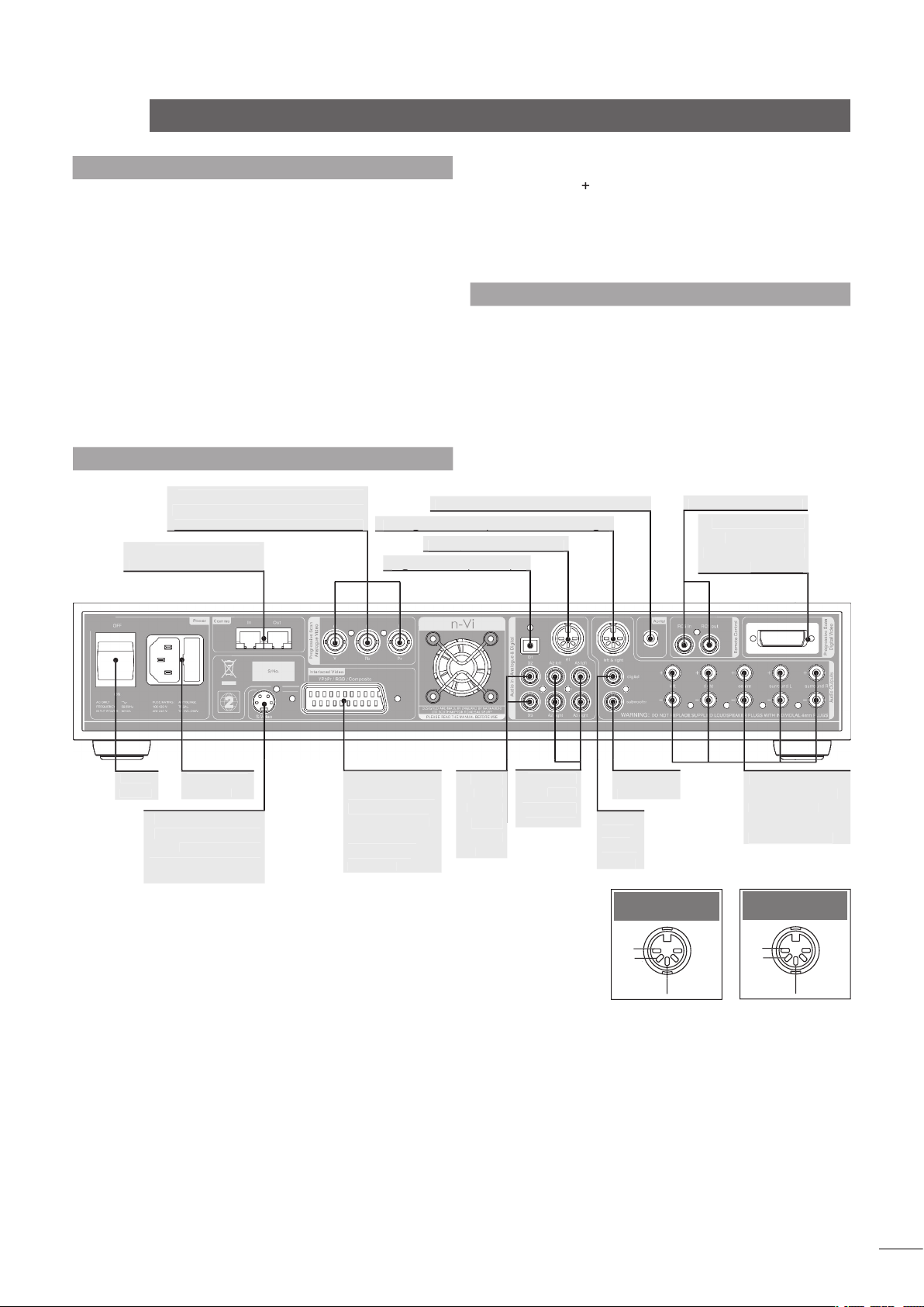
5 Connections
Once the n-Vi is positioned on a rack or furniture
unit it can be connected to a mains supply. Use the
mains cable supplied. Do not switch on the n-Vi until
all audio, video and control connections have been
made.
The appropriate input and output connections will depend on
the type of system the n-Vi is to be used in. An Illustration of
the n-Vi input and output connections can be found on the page
opposite while a diagram illustrating the n-Vi integrated with an
existing stereo system can be found in Section 12.
It is important that high quality cable is used for signal and
speaker connections. Your local retailer or distributor will be
able to offer advice.
5.1 Signal Inputs
The n-Vi can accept three digital and four analogue audio
inputs for the connection of external source equipment. Two
of the digital inputs are connected via RCA-phono sockets and
one via an optical connector. Two of the analogue inputs are
connected via RCA-phono socket pairs and one via a 5-pin DIN
socket. One RCA-phono analogue input socket pair (Input A3)
is duplicated on the n-Vi front panel with a stereo 3.5mm jack
socket. This socket is intended for the temporary connection of
portable music players. Insertion of a plug into the front panel
jack socket will automatically switch the n-Vi to this input. If any
equipment is simultaneously connected to the rear panel A3
input sockets its audio signal will be mixed with the front panel
signal. Removal of the front panel input plug will automatically
switch the n-Vi to the previously selected input.
If the n-Vi has a DAB/FM Radio Upgrade fitted it will also have
an F-Type radio aerial input socket on the rear panel. Indoor
aerials can be used although best results are likely to be
obtained from roof aerials mounted as high as posssible. Use
high quality 75Ω aerial cable for connecting aerials.
Use of an aerial preamplifier may disturb the FM muting
operation of the tuner and may cause other problems. Such
preamplifiers should therefore only be used as a last resort.
An aerial combining unit may be used to combine signals from
separate DAB and FM aerials. Your local retailer or distributor
will be able to offer specific advice on local DAB and FM signal
reception.
For details of all signal input sockets see Diagram 5.7.
5.2 Control Inputs
The n-Vi provides control inputs that enable it to be integrated
with remote handset (RC5) signal repeaters and optionally
with multi-room equipment control systems. The RC5 signal is
connected through a single RCA-phono socket and the optional
multi-room control input connected through an RJ45 socket.
For details of all control input sockets see Diagram 5.7.
5.3 Video Outputs
The n-Vi can provide video outputs in a number of different
formats on a variety of connection sockets. Each format
and socket is appropriate for alternative display types - TV,
CRT Monitor, TFT Monitor, Plasma, Projector, etc. - and it is
important for the best picture quality that the appropriate
socket is used. Table 5.3 lists, in order of preference,
connection formats for any display device. Select, from the
connection options available on your display, the one nearest
the top of the list. For details of all video
output sockets see Diagram 5.7.
5.4 Audio Outputs
The n-Vi provides one stereo analogue audio
output via a 5-pin DIN socket and one digital
audio output via a single RCA-phono socket.
These sockets enable the n-Vi to be connected
to an external audio preamplifier or alternative
multi-channel decoder respectively. In the
case of multi-channel programme material,
the signal present on the analogue output is
the front left and right channels. Analogue
programme material input to the n-Vi from an
external source is not available from the digital
output. The n-Vi also provides one analogue
subwoofer output via a single RCA-phono
socket. For details of all audio signal output
sockets see Diagram 5.7.
n-Vi
Connections
Type
3 x BNC
Analogue Progressive Scan
YPbPr
3 x BNC
Analogue Progressive Scan
Analogue Interlaced
YPbPr
Analogue Interlaced
Analogue Interlaced
Analogue Interlaced
Section 10 carries an explanation of the video formats
listed.
RGB progressive scan output is disabled when replaying
Macrovision encoded material.
Rank
Order
First
Second
Third
Fourth
Fifth
Sixth
Seventh
Table 5.3
Preferred Video Connections
Page 7
n-Vi
5.7 Rear Panel and Connections
Table 5.3
Analogue audio input one
Analogue audio input one
Analogue audio output. Front left and right
Analogue audio output. Front left and right
two and
three
Analogue
front, centre, left
DIN Audio Input
DIN Audio Output
Connections
5.5 Speaker Outputs
The n-Vi provides five speaker output sockets each rated at
90 watts into 4Ω. The five speaker outputs are intended to
be connected to the front left, front right, centre, surround
left and surround right speakers. In order to comply with
European safety legislation speakers should be connected
using the supplied Naim Audio n-Vi speaker plugs only. Naim
Audio speaker cable is recommended although alternatives are
possible. Your local retailer or distributor will be able to offer
advice.
When connecting speakers ensure that each positive pin -
identified by a “
” mark on the side of the connector body - is
always inserted to the positive output sockets. Also ensure that
the connections at the speaker are connected with the same
polarity. For details of the speaker output sockets see Diagram
5.7.
5.6 Control Outputs
The n-Vi provides control outputs that enable it to be integrated
with remote handset signal (RC5) repeaters and optionally
with multi-room equipment control systems. The RC5 output is
connected via a single RCA-phono socket and the optional multiroom control output is connected via an RJ45 socket. For more
detail on connection to the control input sockets see Diagram
5.7.
Page 8
n-Vi
Control and Setup
6 Control and Setup
Once all the input and output connections are made
the n-Vi can be set up. Although the n-Vi can be
set up and controlled from its front panel, many
parameters are best set from the listening position,
so use of the NARCOM DV handset is recommended.
When initially switched on from the rear panel, the n-Vi will,
after a short delay, enter standby mode. Standby is indicated
by an illuminated front panel
button. To wake the n-Vi
press the handset
key or front panel
button.
The n-Vi will wake in either the factory default state, if it is
previously unused, or in the state in which it was last shut
down. Once the n-Vi is switched on, the video display and any
other associated equipment should also be switched on.
The n-Vi can be returned to its factory default settings by
pressing and holding the handset clear key with no disc loaded.
6.1 The User Interface
The n-Vi can generally be operated from its front panel or
from the
remote handset in either
AV
or
modes. The On Screen Display and Front Panel Display provide
operational feedback.
If nothing is displayed when the n-Vi and display are first
switched on some Front Panel Setup video output options may
need to be changed. See Section 8.1.
The n-Vi has two setup routines.
(Section
7) and
(Section 8).
On Screen Setup
configures parameters that apply to system-wide setup, DVD
playback and video display.
Some On Screen Setup parameters can also be accessed
and adjusted via Front Panel Setup.
During
, all functions are accessed via a
cascading menu system with the handset
(up),
(down),
(left),
(right) and
keys. To navigate through the top
level and second level menus use the handset
)
and
)
keys. To confirm a selection press the
key. To
return to the previous menu without making a selection or a
change use the
(return) key, or press
to exit from the
setup menus.
To navigate through the third level menu use the handset
and
keys. To increase or decrease a parameter
value use the
and
)
keys respectively. Use the
key to confirm the setting. To return to the previous menu
without making a selection or a change use the
(return) key.
Press
to exit from the setup menus.
The handset clear key can be used at any time to clear any
On Screen Display.
During
, functions are accessed via a
cascading menu system with front panel
,
,
,
and
buttons providing menu
and
commands. These buttons are illuminated in setup mode. In
normal mode the buttons revert to operating as described
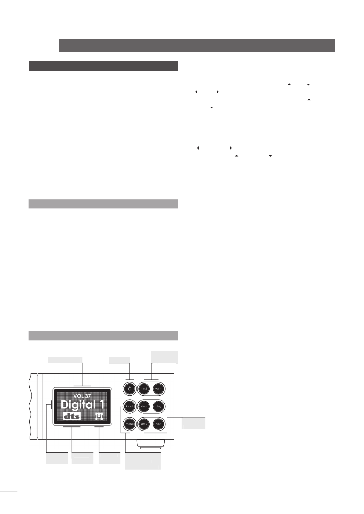
below and illustrated in the diagram.
The handset navigation keys can also be used for Front
Panel setup.
Switches the n-Vi in and out of standby mode.
Decreases volume
vol+:
Increases volume
Selects next signal input
Selects next AV decode mode
Stops playback. Press while stopped opens drawer.
Starts playback. Press while in play pauses play.
Press while drawer open closes drawer.
Selects previous chapter or track.
Selects next chapter or track.
The n-Vi front panel display provides feedback of volume level,
input selection, decode mode, channel scheme and, if the
optional DAB/FM tuner is fitted, radio station identity and data.
The front panel display will switch off after two minutes of
inactivity.
transport
transport
Volume
Diagram 6.1.2
Front panel controls and display.
Page 9
The term “channel scheme” describes the array of speakers in
use. The channel scheme operating at any time is linked to the
input signal, speaker setup and decode mode and is illustrated
on the n-Vi front panel display by an icon in the bottom right
hand corner (See Diagram 6.1.3). The icon changes as different
input signals and decode modes are selected (either manually
or automatically) or speaker setups are specified.
The icon represents a listening room with front left, centre,
front right, surround left, surround right and subwoofer
speakers. Each speaker element within the icon shows or hides
to denote presence in the speaker setup, grows or shrinks to
reflect “large” or “small” specification (see Paragraph 7.6.1),
or is filled or empty to denote its presence or absence in the
channel scheme.
n-Vi
Control and Setup
Diagram 6.1.3
Front panel display channel scheme icon
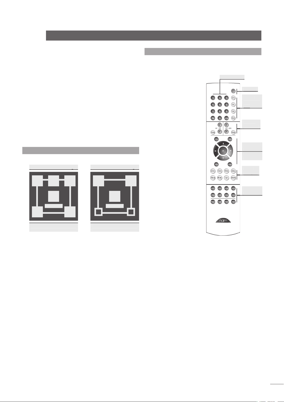
6.2 The NARCOM DV Handset
The NARCOM DV is a dedicated remote handset for the n-Vi,
DVD5 and AV2. It will also operate the core functions of a Naim
CD player, preamplifier or
integrated amplifier.
The
keys switch the handset
mode of operation as
appropriate to different
components (preamplifier,
CD, AV, DVD, n-Vi).
Switches the action of
appropriate keys to operate
a preamplifier or integrated
amplifier.
Switches the action of
appropriate keys to operate
a CD player.
Switches the action
of appropriate keys to
operate an AV2 audio-visual
processor or n-Vi system
(including DAB/FM module).
Switches the action of
appropriate keys to operate
a DVD player or n-Vi system
(including DAB/FM module).
An audio CD played
in a DVD/n-Vi player would
still be controlled with the
handset in DVD mode.
Depending on the System Component setting and, in some
cases signal input selected, the
keys select disc titles,
groups, tracks or chapters or tuner presets.
To select DVD titles or DVD-A groups place a leading zero
before the required title or group number.
The twin sets of
Volume
and
keys remain available to
either an AV processor (or n-Vi) or preamplifier regardless of the
setting of the System Component keys.
The
keys will switch between CD and DVD
player operation depending on the
key
selection. If preamplifier or AV is selected the Player Transport
keys will operate the last component type selected.
Volume
transport
transport
Example of a channel
scheme icon illustrating
a 5.1 system with large
front, centre and surround
speakers and a subwoofer.
Example of a channel
scheme icon illustrating a
4.1 system with large front
speakers, a subwoofer and
inactive small surround
speakers.
As a stereo signal has
no native subwoofer content
Bass Mix has been enabled
to generate subwoofer
information.
Page 10

n-Vi
Control and Setup
6.3 Recommended Initial Setup
The n-Vi incorporates numerous features and facilities, many
of which may initially be left at their default settings until later
preferences have been established.
Six setup stages are however necessary to establish a basic
setup for satisfactory video and multi-channel audio playback of
audio and audio-visual programme material. These stages, with
their owner’s manual section numbers, are listed below. Each
is also accompanied in the body of the owner’s manual by an
exclamation mark graphic:
Setting the Video System and Output Format ensures that the
n-Vi is configured correctly for the display connected. Can be
set from either the On Screen or Front Panel menus.
The default setting is auto.
Sets the video output aspect ratio appropriately for the display
connected.
The default setting is 16:9.
Sets the video output colour format (RGB, YPbPr) appropriately
for the display connected.
The default setting is YPbPr.
Defines the size of each speaker (small, large or none)
connected to the n-Vi.
The default setting is 5.1 with large speakers.
Defines the distance of each speaker from the listening
position.
The default setting is 0.
Sets the relative volume level of each speaker in the system.
The default setting is 0.
!
Page 11

n-Vi
On Screen Setup
7 On Screen Setup
On Screen Setup configures parameters that apply
to system-wide setup, DVD playback and video
display.
To begin the setup procedure insert a DVD and, after waiting for
the n-Vi to read the disc contents, press the remote handset
key. The top level setup menu will be displayed.
If nothing is displayed when the n-Vi and display are first
switched on some Front Panel Setup video output options may
need to be changed. See Section 8.1.
The top level setup menu provides access to
Audio Setup
and
options.
On Screen Setup help text can be accessed by pressing the
handset menu key.
7.1 DVD Playback Setup
Selection of
from the top level menu generates
a second level menu comprising the options described and
illustrated below. The availability of some options in the second
level menu is dependent on the content of the DVD.
Enables the selection of alternative DVD audio tracks if any are
present on the disc. The alternatives may include sound-track
languages and audio encoding format (Dolby*, DTS, etc.). If no
alternative is available no options will be displayed. The disc
must be playing for audio track selection to be available.
Audio tracks can also be directly selected during playback by
pressing the handset audio key. Not all discs offer direct selection.
Enables the selection of alternative camera angles if any are
present on the disc. If no alternative is available no options
will be displayed. The disc must be playing for camera angle
options to be available.
Camera angles can also be directly selected during playback
by pressing the handset angle key.
Enables the display and selection of alternative DVD subtitles
if any are present on the disc. If no alternative is available no
options will be displayed. The disc must be playing for subtitle
options to be available.
Subtitles can also be directly selected during playback by
pressing the handset subt key.
Sets the n-Vi to begin playback as soon as the drawer is
closed. Select from
or
.
Closing the drawer with the front panel stop button overides
Auto Play. The n-Vi will remain stopped.
Selects the preferred subtitle language. When subtitles are
switched on from either the handset
button or from the
n-Vi menu the subtitle preference language will be shown
if ‘preference’ is selected. If the preferred language is not
available the disc default will be shown.
Selects the disc-independent
Audio Language Preference
.
Auto
will select the disc default. If a disc is loaded that does
not carry the selected preference the audio output will switch to
the disc default. The audio track preference will automatically
play if a preference is set and available.
Selects the disc-independent
Audio Format Preference
.
Auto
will select the disc default. If a disc is loaded that does not
carry the selected preference the audio output will switch to the
disc default. The audio track preference will automatically play
if a preference is set and available.
7.2 System Setup
Selection of
from the top level menu generates
a second level menu described and illustrated below.
Sets the system
to display on screen when player
adjustments are made.
Sets the volume
to display on screen when volume
adjustments are made.
MENU
DVD playback
system setup
video setup
prog. scan setup
audio setup
speaker setup
parental control
exit menu
audio track
camera angle
subtitle
DVD auto play
subtitle pref.
audio lang. pref.
audio fmt. pref.
1 English AC-3
up/down to select
ok to confirm
left or return to go
back with no change
menu for help
4
5
6
MENU
DVD playback
system setup
video setup
prog. scan setup
audio setup
speaker setup
parental control
exit menu
status bar
status bar volume
status bar decode
status bar delay
screen saver
on
up/down to select
ok to confirm
left or return to go
back with no change
menu for help
4
5
6
Page 12

n-Vi
On Screen Setup
Sets the decode mode
to display on screen when
mode changes are made.
Sets the length of time, from one to ten seconds, that the
remains visible following a control command.
Sets a
to operate after five minutes of display
inactivity. Select from
and
.
Only disable the Screen Saver if the display is not sensitive
to “burn-in”.
7.3 Video Setup
Selection of
Video Setup
from the top level menu generates a
second level menu described and illustrated below.
output. This menu overrides the Front Panel video set up
described in Section 8.1
If the display is working satisfactorily this setup stage may
not be required.
The selection of
,
or
depends on the capability
of the display device connected. Many displays are limited
either to PAL or NTSC and if this is the case for your display
the appropriate option should be selected. The n-Vi will convert
PAL encoded programme material to NTSC if NTSC is selected,
or convert NTSC to PAL if PAL is selected - display quality may
however suffer.
If the display supports both
and
the
option
should be used. Auto switches the DVD output to NTSC or PAL
depending on the disc format. The combination of a multi-
standard display and the
option ensures the highest video
quality as no format conversion need take place.
If Auto is selected the On Screen Display will show “Auto”
folllowed by the currently selected format.
A black and white picture is often a sign that a PAL only
display is being fed an NTSC signal.
adjustment is effective when
output is
selected. Black Level defines the brightness level at which
image information will be displayed as black. A video brightness
signal is measured in IRE units on a scale from 0 (black) to
100 (white). In American NTSC encoding the value of 7.5 IRE is
the “black level cutoff”.
Black level adjustment only affects NTSC material.
The player’s
output connector carries video signals
in both
and
forms with two alternate
varieties of the component format -
or
YPbPr
- available.
If using component video from the SCART connector, select the
variety appropriate to the display connected.
Composite and component video and the various signal
formats are explained in Section 10.
Provides three display
Test Patterns
intended to help calibrate
the player and display combination and ensure optimum
performance. The Test Patterns are primarily intended for
advanced users or video service engineers. Make a note of all
display and n-Vi settings prior to making any adjustments, and
ensure the display user manual is available for reference.
It is not always necessary to make calibration adjustments
based on the test patterns. The n-Vi and display default settings
will in the majority of cases provide excellent results.
Help text for each test pattern is available by pressing the
handset menu key.
The player must be in stop mode to display the test
patterns.
Adjust the display’s
horizontal, vertical, aspect
ratio and zoom controls until
the test pattern is central
and spills over the edge of
the display by approximately 5%. On a wide-screen display the
circle labelled 16:9 should appear undistorted.
Adjust the display’s
brightness until the 0%
box looks black. Adjust the
display’s contrast until the
100% box is a clear bright,
MENU
DVD playback
system setup
video setup
prog. scan setup
audio setup
speaker setup
parental control
exit menu
output format
black level
SCART settings
test patterns
lip sync
aspect ratio
video outputs off
auto (PAL)
up/down to select
ok to confirm
left or return to go
back with no change
menu for help
4
5
6
!
Page 13

n-Vi
On Screen Setup
The display must be viewed
using a 47b blue separation
filter. Adjust the display’s
colour and tint/hue control
until the four large boxes (1, 2, 3 and 4) appear the same
shade of blue.
DVD video and audio can sometimes appear to be a little out of
synchronisation.
provides adjustment in 10mS steps
to compensate for any apparent error. Use the handset
key
to delay the audio and
key to delay the video.
The default value for lip sync is -10 which ensures correct
audio/video synchronisation on the DVI and BNC video outputs. For
correct synchronisation with interlaced video outputs (SCART and
S-Video) lip sync should be set to 0.
For 16:9 (widescreen) displays, non-widescreen programme
material will be accommodated by leaving a proportion of the
display either side of the picture unused. Widescreen material
on 4:3 (conventional) displays can be accommodated by
selecting either the
or
options. The
option uses the full height of the display but dynamically
pans the material to ensure that the important information is
always displayed. The
option displays the material’s
full width but leaves a proportion of the display above and
below the picture unused.
Enables unused video sockets to be selectively switched off
during playback. Switching off the video sockets will improve
sound quality of audio CD and DVD-A material.
All video outputs will operate when player is in stop mode or
when the OSD menu is displayed.
7.4 Progressive Scan Setup
Selection of
from the top level
menu generates a second level menu described and illustrated
below.
The
menus enable selection of the
signal format to be output from the player’s
sockets.
The signals available from the BNC sockets provide improved
quality over the SCART and S-Video outputs.
The
signal
(RGB, YPbPr).
YPbPr is the appropriate selection for most programme
material. Video colour formats are explained in Section 10.
Three separate
sub-menus are available. One for
adjustment of the player’s
output, one
for adjustment of the player’s
YPbPr (YUV)
output and one that is common to both.
Each signal channel of the
outputs can be independently
adjusted. For example, to emphasise red, green or blue tones
in an
picture boost the R, G or B channels respectively.
YPbPr
adjustment covers luminance and saturation only.
The picture adjustments common to
outputs
are
Vertical Offset
,
and
YC Delay
.
The
adjustments enable the picture to be properly
centred in the display screen.
YC Delay
adjustment provides compensation for the timing
errors that can occur between the colour and brightness
elements of a video signal. YC Delay is best left at its default
adjustment unless picture abnormalities that cannot be
corrected by any other means are apparent.
Offset and YC Delay adjustment made from this menu will
also be reflected in the DVI output.
No picture adjustment is available on the player’s SCART
and S-Video outputs.
MENU
DVD playback
system setup
video setup
prog. scan setup
audio setup
speaker setup
parental control
exit menu
output format
black level
SCART settings
test patterns
lip sync
aspect ratio
video outputs off
16:9 widescreen
up/down to select
ok to confirm
left or return to go
back with no change
menu for help
4
5
6
MENU
DVD playback
system setup
video setup
prog. scan setup
audio setup
speaker setup
parental control
exit menu
colour format
picture adjust
YPbPr
up/down to select
ok to confirm
left or return to go
back with no change
menu for help
4
5
6
!
!
Page 14

Midnight Mode is not available with analogue material.
Midnight Mode can also be selected directly during normal
operation from the remote handset.
enables a descriptive label to be assigned to each
numbered n-Vi input socket. Inputs can also be disabled (set
to OFF) from this menu. The n-Vi’s internal “inputs” - Disc, DAB
and FM cannot be assigned alternative names.
It is not necessary to assign labels to the inputs but doing
so helps make n-Vi operation more intuitive.
Two labels can be assigned to Analogue Input 3, one for
its rear panel socket and one for its front panel socket. The front
panel input will only be available for selection when a connector is
plugged-in.
7.6 Speaker Setup
Selection of
from the top level menu generates
a second level menu described and illustrated below.
Speaker Size
to be defined. Generally a “small” speaker is an element of a
satellite/subwoofer package, while a “large” speaker is a full-
range type. The “small” left/right option is unavailable if no
subwoofer is present.
Ext (External) Large or Small should be selected if the front
speakers are connected to the n-Vi via an external power amplifier.
enables the preferred distance measurement
units (feet or metres) for the Speaker Distance menu to be set.
n-Vi
On Screen Setup
7.5 Audio Setup
Selection of
Audio Setup
from the top level menu generates a
second level menu described and illustrated below.
Selects the player’s
format from
(i.e Dolby Digital, DTS, etc.) or
(PCM stereo)
options.
The n-Vi must be in stop mode to select audio outputs.
Selection of
routes the front left and right speaker
low frequency signals additionally to the subwoofer channel.
Bass Mix will have no effect when a low frequency effects
(LFE) channel is encoded in the programme material.
Bass Mix is not available on analogue source material.
Selection of
Options provides adjustment of the
,
and
parameters.
“ON” diverts a proportion of the front stereo signal
to the surround channels.
adjustment varies the relative strength of the
centre and front channels, a higher value increasing the
strength of the front channels.
adjustment varies the relative strength of the
surround and front signals, a higher value increasing the
strength of the surround channels.
Pro Logic II Options are only effective when Dolby* Pro Logic
II Music Mode is selected.
Selection of
provides independent
adjustment of the centre channel volume level.
Neo:6 Centre Gain is only effective when DTS Neo:6 Music
Mode is selected.
Selection of
compresses the audio signal and
reduces its bass content to reduce the disturbance of late-night
listening.
MENU
DVD playback
system setup
video setup
prog. scan setup
audio setup
speaker setup
parental control
exit menu
digital audio output
bass mix
Pro Logic II
Neo:6 centre gain
midnight mode
input labels
multi-channel
up/down to select
ok to confirm
left or return to go
back with no change
menu for help
4
5
6
MENU
DVD playback
system setup
video setup
prog. scan setup
audio setup
speaker setup
parental control
exit menu
speaker size
units
speaker distance
test signal
speaker level
front: large
left/right to select
speakers
up/down to select size
ok to confirm
return to go back with
no change
menu for help
4
5
6
!
MENU
DVD playback
system setup
video setup
prog. scan setup
audio setup
speaker setup
parental control
exit menu
digital audio output
bass mix
Pro Logic II
Neo:6 centre gain
midnight mode
input labels
A1 : Analogue 1
left/right to select input
up/down to select label
ok to confirm
left or return to go
back with no change
menu for help
4
5
6
Page 15

7.7 Parental Control Setup
Selection of
from the top level menu
generates a second level menu described and illustrated below
that enables a
to be set in order to restrict access to
unsuitable programme material.
Enter the existing or a new four digit passcode using the
handset
to gain access to the following
Parental Control menus. Ensure you keep a record of the
passcode.
Enter a new
if you wish to change the existing one.
Ensure you keep a record of the new pass code.
Select either
or
. With Parental Control enabled,
the Parental Control options defined in the following two menu
stages are operational. Parental Control disabled switches off
all restricted access features.
Selects the rating level above which a Parental Control
passcode is required before a DVD can be viewed.
Some DVDs do not have a rating level encoded. Select
to restrict such DVDs with the Parental Control passcode.
7.8 Exit On Screen Setup
Setting the Parental Control options completes On Screen
Setup. Use the
key or
key to exit On Screen
Setup.
n-Vi
On Screen Setup
MENU
DVD playback
system setup
video setup
prog. scan setup
audio setup
speaker setup
parental control
exit menu
enter passcode
change passcode
parental controls
allowed ratings
unrated titles
_
type passcode
up/down to select size
ok to confirm
return to go back with
no change
menu for help
4
Speaker Distance
speaker from the primary listening position to be defined.
Distance definition is only available for speakers previously
specified (in 7.6.1) as present.
The distances need not be defined accurately. Plus or minus
300mm (1 foot) is adequate.
The centre speaker should be no further away from the
listening position than either front speaker.
Test Signal
switches the n-Vi into the speaker
test mode. Ensure that the n-Vi speaker outputs are connected
correctly and that any subwoofer is connected, switched on and
appropriately set up.
n-Vi must be in stop mode with the disc input selected and
no disc loaded.
(after switching on the
Test Signal)
enables subjective matching of the volume level
of each speaker channel. Begin with the Centre speaker level
set to O then select each speaker channel in turn and, seated
at the listening position, adjust each volume level so that the
speakers sound approximately equally loud.
If the test signal is either too loud or too quiet the overall
system volume can be adjusted with the handset volume keys.
The adjustment level for the subwoofer output on the n-Vi
should be set somewhere between the maximum and minimum
settings needed for the other loudspeakers in the system. The
volume control on the subwoofer itself should then be adjusted to
give the best results.
MENU
DVD playback
system setup
video setup
prog. scan setup
audio setup
speaker setup
parental control
exit menu
speaker size
units
speaker distance
test signal
speaker level
left: 0’
left/right to select
speakers
up/down to adjust distance
ok to confirm
return to go back with
no change
menu for help
4
5
6
!
MENU
DVD playback
system setup
video setup
prog. scan setup
audio setup
speaker setup
parental control
exit menu
speaker size
units
speaker distance
test signal
speaker level
centre: 0
left/right to select
speakers
up/down to adjust level
ok to confirm
return to go back with
no change
menu for help
4
5
6
!
Page 16

n-Vi
Front Panel Setup
8 Front Panel Setup
Front Panel Setup provides an alternative setup
routine for some parameters and provides access
to Video System and Format parameters should
these need adjustment before the n-Vi and display
combination will operate correctly. Front Panel
Setup also provides access to a number of setup
parameters that are not available via On Screen
Setup.
To enter Front Panel Setup either press and hold the handset
key or press and hold the front panel
button.
On Screen and Front Panel setup modes cannot be used
simultaneously.
8.1 Video System and Output Format
If nothing is displayed when the n-Vi and display are first
switched on, two video output options on the n-Vi may need
to be changed. These options select between the
,
or
, and between
Video Colour Format
options. The
Video Colour Format
options apply only to the
n-Vi
output sockets, the choices being
To change the options proceed as described in the following
paragraph.
Press and hold the handset
key to put the n-Vi into
mode. Use the handset or front panel menu
buttons (see Paragraph 6.1.2) to select
Video
from
the main menu. Select
from the next menu and then
,
or
depending on the format required by the
display.
NTSC/PAL selection is only likely to require a specific choice
(i.e not auto) if the display is not capable of displaying both.
Use the
buttons to return to the previous menu and
select
followed by either
YPbPr
or
as required by
the display. Use the navigation buttons to return to the main
menu.
A
logo visible in the centre of the display screen confirms
that the Initial Video Options are set correctly.
8.2 Speaker, Input and Audio Setup
Front Panel Setup provides Speaker, Input Label and Audio
setup routines. If these setup stages have been completed
through On Screen Setup it is not necessary to repeat them.
Size
followed by
Select
either
or
Use the front panel
buttons to return to the previous
menu and select
followed by
,
or
.
Continue by selecting
,
or
for the surround
speakers and
or
for the subwoofer.
Return to the Speaker menu and select
followed by
followed by
or
. Selection of
or
defines the distance measurement units used. Return to the
Distance menu and select each speaker in turn specifying the
approximate distance of each one from the listening position.
Return to the Speaker menu and select
Test Signal
to switch
the test signal
then access the level adjustment menu for
each speaker channel. Begin with the Centre speaker level
set to O then select each speaker channel in turn and, seated
at the listening position, adjust each volume level so that the
speakers sound approximately equally loud.
If the test signal is either too loud or too quiet the overall
system volume can be adjusted with the handset volume keys.
When all the speaker levels have been set use the
keys to switch the test signal
and return to the Main menu.
Select
from the main menu and use the
keys to select each input in turn and then to select
from the presented list of label options.
Select
Audio
from the Main menu to enter the audio menu.
routes front left and right loudspeaker bass
information additionally to the subwoofer.
diverts a proportion of the front stereo signal to the
surround channels.
Width
adjusts the balance between the centre channel and the
left and right channels. Selection of a higher value increases
the volume of the left and right channels.
adjusts the balance between the front and surround
channels. Selection of a higher value increases the relative
strength of the surround channels.
provides independent adjustment of the
centre channel volume level.
compresses the volume and reduces the bass level of
movie soundtrack material and can help reduce disturbance to
others from late night listening.
Width, Panorama Dimension and Midnight functions are
only effective with Dolby Pro Logic II Music encoded material.
Midnight can also be selected directly during normal
operation from the remote handset.
Neo:6 Centre Gain is only effective when DTS Neo:6 Music
Mode is selected.
!
!
!
!
Page 17

n-Vi
Front Panel Setup
8.3 Miscellaneous Setup
Select
from the main menu to enter the other
settings menu.
The other settings menu provides access to two further display
interface options -
and
.
Selecting
switches on a temporary status bar
indication of volume on the display screen.
Selecting
switches on a temporary status
bar indication of the audio-visual decode mode on the display
screen.
Return to the previous menu after each selection and then
back to the main menu when each option is set.
8.4 Clock Setup
Clock functions are only available if the FM/DAB tuner
module is fitted.
Select
from the Main menu to enter the clock menu.
The n-Vi internal clock can be set manually or take its time
automatically from the digital radio signal.
To set the clock manually select
from the Clock menu
and use the
keys to select and adjust the date, day,
hours and minutes.
To set the time using the DAB signal select
from the
Clock menu and
then use the
keys
to select
Yes
or
.
Return to the previous menu after each selection and then
back to the main menu when the clock options are set.
8.5 Alarm Setup
Alarm functions are only available if the FM/DAB tuner
module is fitted.
Select
Alarm
from the Main menu to enter the alarm setup
routine.
The alarm function switches the n-Vi out of standby mode
and selects a signal source at a specified time. Five different
alarm points can be set, as can alarm
(Daily, Day,
Weekdays, Weekends),
,
,
,
Volume
,
Volume Ramp
and
. Use the
keys to
select the required alarm (1 to 5), the required options for each
one and finally to select
or
.
An alarm symbol will show in the n-Vi front panel display at
all times while an alarm is set.
8.6 Exit Front Panel Setup
Setting the Alarm options completes Front Panel Setup. Use the
(clear) key, or press
to exit Front Panel Setup.
Page 18

n-Vi
9 Operation
Once all the system setup options described in
Section 7 and 8 are selected the n-Vi is ready
for use. Control of disc transport and selection
of disc dependent display options can be carried
out from either the player front panel or from the
handset. The following paragraphs describe both the
control functions and the front panel and handset
operations.
The n-Vi supports NTSC and PAL DVD, “Red Book” Audio CD,
DVD-A Stereo, DVD-A multi-channel, DVD±R, DVD±RW, CD-R,
CD-RW and most copy protected Audio Discs.
Use the front panel stop button to open the drawer.
The large variety of disc manufacturing processes and
formats available means that on rare occasions a disc apparently
falling into the one of the above categories may not play correctly.
You should return the disc to the retailer if this occurs.
DVD region coding is sales territory dependent and is
specified on the rear panel of the n-Vi.
The front panel display will switch off after two minutes of
inactivity.
9.1 Input Selection and Volume Control
To select an input use the handset
key. The front panel
button will also sequentially select inputs. When a
new input is selected the n-Vi display will sequentially show
the input source and the current decode mode settings if
appropriate.
The n-Vi may take a moment to display inputs and decode
modes when new inputs are selected as it locks-on to and
identifies any signals.
To adjust the overall volume use the handset
vol
and
vol
keys or front panel
vol+
and -
vol
buttons.
9.2 Playback Control
Press the
button once.
Press the
key once.
Press the
button once.
Press the
key once.
Play will normally re-start from the point at which a disc
was last stopped. Pressing stop while a disc is already stopped
will clear this “resume” memory for the specific disc. The resume
memory holds “stop point” data for the last 10 discs played.
Press the
button once.
Press the
key once.
Press the
button once.
Press the
key once.
Press the
button (while play is underway).
Press the
key once.
Press the
key once while player is paused.
For 2 X speed press and hold the
button
while
is underway. Further presses of the
button will
cycle through 4 X, 8 X, 16 X, 30 X, 60 X (for DVDs) or 4 X, 8
X, 16 X and (for CDs). To resume normal play scroll through to
play speed or press
on the front panel or handset.
Press the
ffwd
(
) key once for 2 X speed. Further
presses generate fast forward speeds as described above.
For 2 X speed press and hold the
button
while
is underway. Further presses will cycle through 4 X,
8 X, 16 X, 30 X, 60 X (for DVDs) or 4 X, 8 X, 16 X (for CDs). To
resume normal play scroll through to play speed or press
on the front panel or handset.
Press the
frwd
(
) key once for 2 X speed. Further
presses generate fast reverse speeds as described above.
Press the
key once for half speed playback
followed by the
ffwd
(
) and
frwd
(
) keys to select further
slow forward or reverse speed options.
To open the drawer press the
button when
the player is stopped. When open, press the
or
buttons to close the drawer.
Press the
key to open or close the drawer, or
the
or
keys to close the drawer.
Press the
key to set a repeat start point
and again at the desired time to set a repeat end point. The
player will continuously repeat the programme between the
two selected points. Press
a third time to cancel. Press
Operation
Page 19

n-Vi
and hold the
key to access the
mode. While
the repeat disc status bar is showing press the
key to
cycle through and select
,
and
functions.
To select a specific track or chapter while a disc
is loaded simply press the appropriate handset
key. To
select a title or group add a zero before the number.
The mem function allows the user to store and
recall a specific point on a maximum of five discs.
To store a mem bookmark press and hold the handset
key
at the desired time point.
To recall a bookmark, with the bookmarked DVD loaded, press
the handset
key. The DVD will jump to the bookmark.
9.3 Playback Options
Press the
key to scroll through the
available camera angle options.
This function can also be found in the main setup menu.
Press the
key to scroll through the available
subtitle options.
This function can also be found in the main setup menu.
Press the
key to scroll through the
available audio tracks.
This function can also be found in the main setup menu.
Press the
zoom
key to scroll through the
available zoom levels. Use the arrow keys (
) to
navigate around the picture.
9.4 Accessory Functions
The n-Vi has four accessory functions accessible at all times
from the handset. The display will temporarily indicate selection
or de-selection of these functions.
The
key immediately reduces the volume to zero. A
second operation restores the volume to its previous level.
The volume can also be restored after a mute command by
turning the front panel volume control to zero and then up to a
normal listening level.
Operation
The
key switches the n-Vi front panel display off. When
switched off the display will temporarily flash information when
changes are made. A second operation will restore the display.
The
key compresses the signal and reduces the bass
content. It can help reduce disturbance to others from late
night listening.
Midnight Mode is not available with analogue material.
The
key returns the n-Vi to standby mode. The standby
button only will remain illuminated.
9.5 Decode Modes - Selection and Availability
The signal decoding behaviour and options of the n-Vi are
dependent on both the source programme material and
the speaker setup. With some digital programme material,
decoding options are user definable - although the results of
processing for example, music material with movie decoding
mode are unpredictable. In other cases however the n-Vi will
automatically identify encoded material and only make available
the appropriate decoding option or options. The n-Vi front panel
and on screen display will show each decoding mode selected
or imposed.
Stereo analogue inputs to the n-Vi are always routed direct to
the front left and right speaker outputs and cannot be decoded.
To select a decode mode use the handset
key or the
front panel
button. The n-Vi will store the last selected
decode mode for each type of signal and for each input. The
decoding options and display for each type of programme
material, and the speaker channel schemes for each are
detailed in Tables 9.5 and 9.6
9.6 Channel Schemes and Speakers
The term “channel scheme” describes the array of speakers in
use. The channel scheme operating at any time is linked to the
input signal, speaker setup and decode mode and is illustrated
on the n-Vi front panel display by an icon in the bottom right
hand corner (See Diagram 6.1.3). The icon changes as different
input signals and decode modes are selected (either manually or
automatically) or speaker setups are specified.
The icon represents a listening room with front left, centre,
front right, surround left, surround right and subwoofer
speakers. Each speaker element within the icon shows or hides
to denote presence in the speaker setup, grows or shrinks to
reflect “large” or “small” specification (see Paragraph 7.6.1),
or is filled or empty to denote its presence or absence in the
channel scheme.
Page 20

Analogue
Yes
Yes
Yes
Yes
Yes
Yes
Yes
Yes
Yes
Yes
Yes
Yes
Yes
Yes
Yes
Yes
Yes
Yes
Yes
Yes
Yes
Decode
Modes
Analogue Direct
Mono
Stereo
Dolby PL II Music
Dolby PL II Movie
DTS Neo:6 Cinema
DTS Neo:6 Music
Auto
Table 9.6
Decode Modes - Availability with Programme Material Types
n-Vi
Operation
Channel schemes are also expressed by terms such as
“5.1” or “3/2.1” Taking 5.1 as an example, the “5” refers to the
number of conventional speaker channels and the “.1” refers to a
subwoofer. In 3/2.1 the “3” refers to the number of front channels
employed (in this case, left, right and centre), the “2” refers to the
number of surround channels and the “.1” refers to a subwoofer.
Tables 9.5 and 9.6 refer to channel schemes in this manner.
Yes
Yes
Yes
Yes (“small” or Bass Mix selected)**
Yes
Yes
Yes (“small” or Bass Mix selected)**
Yes
Yes
Yes
Yes
Yes
Yes (“small” or Bass Mix selected)**
Yes
Yes
Yes
Yes
Yes
Yes (“small” or Bass Mix selected)**
Yes
Yes
Yes
Yes
Yes
Yes (“small” or Bass Mix selected)**
Yes
Yes
Yes
Yes
Yes
Yes (“small” or Bass Mix selected)**
Yes
Yes
Yes
Yes
Yes
Yes
The subwoofer
channel will only operate
if Bass Mix (Paragraph
7.5.3) or “small” speakers
(Paragraph 7.6.1) are
selected.
Source
Format
Analogue
Digital Stereo
Digital Stereo
Digital Stereo
Digital Stereo
Digital Stereo
Digital Stereo
Dolby Digital/DTS 5.1
Table 9.5
Source Material, Decode Modes and Channel Schemes
Decode
Mode
Analogue Direct
Mono
Stereo
Dolby PL II Music
Dolby PL II Movie
DTS Neo:6 Cinema
DTS Neo:6 Music
Auto (5.1 source)
An alternative
dedicated subwoofer (or dual
input subwoofer) can be
connected via the analogue
output or speaker output
sockets if required.
Page 21

9.7 Surround Encoding Technology
Some feature films have carried the multi-channel sound
tracks necessary for “surround sound” since the 1950s. But
only since the mid 80’s has surround sound been available to
domestic consumers. The technology that first enabled four
channels of audio to be decoded from the stereo soundtrack of
consumer media such as video cassette is Dolby Surround Pro
Logic. Since Dolby Surround Pro Logic, and especially following
the introduction of digital products such as DVD, enhanced
encode and decode technologies have been introduced that
enable a greater number of higher quality channels of audio to
be encoded. With digital encoding techniques such as Dolby
Digital and DTS Surround, appropriately encoded feature films,
music and even computer games can be reproduced in full-
bandwidth surround sound with up to eight audio channels (left,
right, centre, surround left, surround right, surround extra, low-
frequency effects).
The following few paragraphs provide a short description
and explanation of encoding technologies. Further
technical information can be found at www.dolby.com and
www.dtsonline.com.
Dolby Surround Pro Logic is a matrix decoding process that
generates four output signals (left, right, centre, surround)
from a Dolby Surround encoded stereo input signal. It is built
into virtually every home theatre audio system. The nature of
Pro Logic decoding constrains the single surround channel to
relatively narrow bandwidth.
Dolby Surround Pro Logic II is an improved analogue matrix
technology that provides improved surround performance
on Dolby Surround encoded program material. While earlier
surround programme material is fully compatible with Pro Logic
II, appropriately encoded soundtracks can take full advantage
of its enhancements - which include full bandwidth left and
right surround channels. Pro Logic II also features two distinct
decoding options for “music” and “movie” programme material.
Dolby Digital is a fully digital decoding technology that provides
three full bandwidth front channels, two full bandwidth surround
channels, and one low-frequency effects channel - a channel
scheme known generically as “3/2.1” (or “5.1”). The encoding
technique for Dolby Digital, known as Dolby AC-3, has since
1995 been used on many Video Laser Discs and more recently
on DVD. Dolby AC-3 encoding can also be found on digital
television services. In addition to encoding audio for six channel
replay, Dolby AC-3 incorporates compression techniques that
ease audio data storage and transmission demands and can
enable, for example, a single DVD to carry a complete movie.
A variation of Dolby Digital 3/2.1 is Dolby Digital 2/0. Dolby
Digital 2/0 takes advantage of Dolby AC-3 data compression
in order to reduce the data storage demands of stereo
programme material. The “2/0” denotes the use of just two
main audio channels with no low frequency effects channel.
Programme material encoded for a “2.1” (two main channels
with one subwoofer channel) scheme is also available and can
be handled within Dolby 2/0 decoding.
DTS Surround is an alternative digital audio encoding format
that has become popular with feature film producers and can
therefore be found on many DVDs. The first feature film to
be DTS encoded was Jurassic Park in 1993. DTS Surround
provides a similar 3/2.1 channel scheme to Dolby Digital with
the encoding technology also providing data compression. The
DTS data compression ratio is lower than that in AC-3 however
and it is argued that DTS can provide better audio quality. The
downside of any quality improvement over AC-3 is however
higher data storage requirements.
n-Vi
Operation
Page 22

10 Video Formats Explained
In the early days of domestic video and home
theatre the issue of different video formats and
interfaces did not really arise. There was only one
way of connecting a VCR to a TV - via the aerial
cable. However the growth in domestic high quality
video, along with the introduction of widescreen and
non-CRT displays has meant that video interface
issues, once of concern only to professionals, have
become significant in domestic systems.
The following few paragraphs provide an explanation of some
of the issues and technologies that impinge on the n-Vi, its
installation and operation.
10.1 Interlaced and Progressive Scan Video
Video is nothing more than a series of still pictures displayed
sequentially at such a rate that the brain perceives continuous
motion. A video signal comprises elements that describe the
colour and brightness of each individual display pixel and
an element that describes the necessary timing information
required to create an image. Each picture is “drawn”, pixel by
pixel and line by line, across and down the screen - again at
a rate such that the brain does not distinguish the segmented
nature of the information.
In conventional “interlaced” video, each still picture is drawn
half a screen at a time in two sections (or scans) constructed
from sets of alternate lines. This technique is used to reduce
the amount of information required for each frame. In
“progressive scan” video, rather than being constructed from
two sections, pictures are constructed in a single top to bottom
scan. The result is a significantly sharper, more detailed and
more stable image.
10.2 Video Interface Formats
Table 5.3 lists the video interface formats supported by the
n-Vi in order of preference defined by the display quality
potential of each. There are fundamental technical reasons why
alternative formats can provide different levels of display quality
and an explanation of these provides a useful introduction
to the techniques and technologies of video. The formats are
described, in reverse quality order, over the following paragraphs.
The SCART (Syndicat des Constructeurs d’Appareils
Radiorécepteurs et Téléviseurs) connector first became familiar
on the introduction of high quality domestic video recorders.
These recorders were able to generate both “composite”
and “component” video signals and both, along with stereo
analogue audio, are carried by the SCART. Component video
generally describes those formats that carry the various
elements of the signal on separate cables - sometimes known
as channels.
Composite video is a signal that encodes the three elements
of a moving image - colour, brightness and timing - in a single
signal carried by a single cable. Two different encoding formats
are common - NTSC generally in America and the Far East,
and PAL in Europe. Encoding the signal brings the advantages
of single-wire simplicity and convenience, but the necessary
downstream decoding produces unavoidable and visible
artifacts. Composite video thus offers the lowest display quality
of the options available and should be used if there is really no
other option. Very few contemporary displays or TVs will offer a
composite video input only.
The S-Video format offers the next higher quality video
connection. S-Video is a two channel based connection with the
colour and brightness information separated, and the timing
signal combined with the brightness signal. The separation
of colour and brightness reduces the need for downstream
processing to decode the signals and results in potentially a
sharper image.
In addition to carrying a composite video signal the SCART
interface also carries a set of “RGB” or “YPbPr” video signals
selectable via the video setup menu. RGB denotes the
fundamental Red, Green and Blue components that define
a colour image. A timing signal is combined with the Green
signal. YPbPr is mathematically derived from RGB and denotes
brightness (Y) and two colour difference signals (Pb & Pr). The
video timing signal for the YPbPr format is combined with the
brightness signal. YPbPr carries the same information as RGB
but does so with reduced bandwidth demands. Both RGB and
YPbPr offer a further potential quality increase over S-Video
by again reducing the demands on downstream decoding. It is
marginally preferable to use RGB over YPbPr.
The first connection interface from which a Progressive Scan
signal is available. YPbPr Progressive Scan can be selected for
the BNC interface via the video setup menu.
A Progressive Scan RGB signal is also selectable via the video
setup OSD menu and available from the same three BNC
connectors described in paragraph 10.2.4. RGB is the native
video format of most displays and potentially provides better
quality than YPbPr thanks to reduced demands for downstream
signal processing. As with the SCART RGB interface, the video
timing signal is combined with Green signal.
RGB progressive scan output is disabled (and the screen will
appear blank) when replaying Macrovision encoded material.
n-Vi
Video Formats
Page 23

The DVI interface provides the greatest potential video
quality. DVI is a direct digital connection for digital displays
(LCD, Plasma etc.) and analogue displays with internal digital
to analogue converters. With DVI and a digital display, no
downstream decoding or signal conversion is required so the
display quality potentially matches that inherent in the source
material. The DVI output is HDCP (High-bandwidth Digital
Content Protection) encrypted and only compatible with HDCP
capable displays (the majority of computer DVI displays are not
HDCP capable). HDMI (High Definition Multimedia Interface)
compatible displays can be used with the n-Vi via an adaptor
cable.
11 DAB/FM Tuner
The optional n-Vi DAB/FM radio tuner module
provides access to DAB and FM radio broadcasts.
An appropriate aerial (or aerials) must be connected
to the aerial input before using the DAB/FM module.
See Section 5.7 for advice on aerials.
DAB radio broadcasts are not available in all territories.
The n-Vi treats DAB/FM radio as an internal digital audio source
therefore any appropriately encoded programme material can
be decoded for multi-channel reproduction.
DAB and FM setup and operational menus are only available
through the n-Vi Front Panel display.
With the DAB/FM module installed, clock and alarm functions
become available. These are set up within the Front Panel
Setup routine. See Sections 8.4 and 8.5.
A total of 30 stations, split between DAB and FM, can be stored
as presets.
11.1 DAB Menu and Operation
With the DAB/FM module installed the n-Vi input list will include
a DAB option. Use the handset
key to select this option.
If the DAB/FM module has not been used before the display
will request “scan for stations?” Use the handset
key to
commence the scan (or
key to decline). The n-Vi will
proceed to scan through the DAB radio band searching for
“live” stations. This may take a few minutes.
If the display does not request “scan for stations?” but the n-Vi
has been physically relocated it is advisable to re-scan anyway
by pressing the handset
key (while the DAB input is
selected) and selecting
Press the
key
to begin the scan. The scan may take a few minutes.
Always re-scan if the n-Vi has been moved to a different
location.
n-Vi
DAB/FM Tuner
When the station scan is complete the DAB menu provides
options to select either
tune mode
or
. In tune
mode stations are selected simply by scrolling through the full
list using the handset
(left) or
(right) keys.
In
stations previously stored as presets can be
selected either from the handset
keys, from the
(left) or
(right) keys or the
and
keys.
Some DAB stations do not broadcast at all times and may
be listed as unavailable.
To store a station as a preset select the station followed by
from the DAB menu. Input a preset number from
the handset
keys. Alternatively, presets 1-9 can be
assigned to a station at any time by pressing and holding
the desired handset
key number while the station is
selected. Any station (DAB or FM) previously assigned to that
number will be overwritten.
To delete a station preset select
from the DAB
menu and input the preset number from the handset
keys followed by the
key.
The DAB menu can be selected at any time by pressing the
handset menu key while the DAB input is selected.
With the DAB input selected the handset
(up) or
(down)
keys scroll through the display options of Preset Number,
Station Name, Scrolling Station Info, Programme Genre, Bit-
rate and Signal Strength.
11.2 FM Menu and Operation
With the DAB/FM module installed the n-Vi input list will include
an FM option. Use the handset
key to select this option.
With the FM input selected use the handset
key to enter
the FM menu.
The FM menu can be selected at any time by pressing the
handset menu key while the FM input is selected.
The FM menu provides options to select either
tune mode
or
. In tune mode stations are tuned by scrolling
through the FM band using the handset
(left) or
(right)
keys or entering a frequency using the
keys.
In
selection, storing and deletion of presets works
in exactly the same way as described above in Section 11.2
(DAB menu and Operation).
With the FM input selected the handset
(up) or
(down)
keys scroll through the display options of Preset Number (in
preset mode), Frequency (in tune mode), Station Name (RDS),
Scrolling Station Info (RDS), Programme Genre (RDS) and
Signal Strength.
Page 24

n-Vi
System Connections
12 System Connections
Connection of the n-Vi in a stand-alone AV system
is straightforward. Each speaker output should
be connected to the appropriate speaker, the
subwoofer output connected to an active subwoofer
and a video display connected to the appropriate
video output. (See Diagram 5.7).
Integration of the n-Vi in an existing Naim system requires
a little more care and thought however. The diagram below
shows an n-Vi integrated in a system comprising a NAC252
preamplifier, Supercap power supply and NAP250 power
amplifier. The principles applied in this connection scheme are
similarly appropriate in any alternative systems but, if there
is any doubt, your local retailer or distributor will be able to
advise.
The preamplifier input must be set to unity gain mode. See
the preamplifier Owner’s Manual for further information.
12.1 n-Vi with NAC252, Supercap and NAP250
To subwoofer
Page 25

n-Vi
Trouble-shooting
13 Trouble-shooting
The following list of typical problems and solutions
will help ensure trouble-free n-Vi installation and
use.
13.1 Video and Disc Playback
The n-Vi is set to YPbPr mode and the display is set to RGB
mode. See Section 7.4.1
The n-Vi is set to RGB mode and the display is set to YPbPr
mode. See Section 7.4.1
The n-Vi is converting from PAL to NTSC or NTSC to PAL. Set
n-Vi video output to auto or PAL/NTSC to match the format
recorded on the DVD in use. See Section 7.3.1
Handset is set to the wrong mode. Press the handset
key.
Handset batteries flat?
Fluorescent lights, reflective surfaces (rooms with lots of
windows) and LCD display panels can interfere with remote
control infrared signals. Switch off lights and display panels to
determine the cause. Re-positioning the n-Vi may be necessary
to cure the problem.
Handset has been inadvertently re-configured to work on a
different remote channel;
Press handset
key. While simultaneously holding the
and
keys press
key.
Press handset
key. While simultaneously holding the
and
keys press
key.
Video quality is poor using SCART.
SCART has two video signals, composite and YPbPr/RGB. The
display may be set to composite.
Progressive scan video is only available via the BNC or DVI
connections.
The n-Vi is set to NTSC and the display is set to PAL. See
Section 7.3.1
DVI to HDMI adapters are available from accessory retailers.
Optical DVI leads up to 500 metres long are available.
The display is not HDCP compliant. To meet DVD licensing
requirements the n-Vi DVI output is content protected using
HDCP. The display will need updating.
The picture disappears when “play” is selected.
The n-Vi video outputs are switched off. See Section 7.3.7
A Macrovision encoded disc is loaded and the display is
connected via RGB.
The image is not centred.
Check both the display and n-Vi alignment controls. See
Sections 77.3.4 and 7.4.2
The n-Vi remembers the last 10 discs played and the playback
position when they were ejected. To start from the beginning
load the disc, ensure the n-Vi is in stop mode then press
on the handset.
When in stop mode press the front panel
button.
The fan comes on.
When the unit becomes warm the fan switches on to regulate
the temperature. Ensure the unit is well ventilated and not
directly stacked on top of any other equipment.
13.2 Audio
The only formats that have native subwoofer information are
Dolby Digital and DTS 5.1 soundtracks. If you require sound
from the subwoofer enable bass mix from the on-screen or
front panel menu. See Section 7.5.2
Processing modes including bass mix cannot be applied to
analogue inputs. To generate subwoofer information from an
analogue source the subwoofer can either be connected at
line level to the n-Vi left and right output socket (line level)
or directly to the loudspeaker terminals (speaker level). The
subwoofer’s low pass filter will have to be set manually.
Page 26

n-Vi
Trouble-shooting
Dolby Pro Logic II or Neo:6 surround mode is probably enabled.
Use the handset
key to select Stereo or auto.
Ensure test signal is switched on then select a speaker in the
level setup menu. See Sections 7.6.4 and 7.6.5
Ensure the master volume is not set to zero. Use the the
handset volume keys to adjust.
Player must be in stop mode with the disc input selected and
no disc loaded.
Test signal too quiet.
Use the handset volume keys to adjust the overall volume level
Ensure all speakers are correctly connected and defined in the
On Screen Setup.
Tip:
Press stop and listen for a very quiet hiss
from each speaker. You will need to be very near the speaker to
hear this. If a speaker has no hiss check the connections and
the On Screen Setup.
Ensure the n-Vi is not in stereo mode.
Check the disc has a 5.1 soundtrack (normally shown on the
back of the cover).
Press the audio button on the remote to cycle through the
available audio tracks. Some discs prohibit change of audio
format from the handset. In these cases the audio track must
be changed from the DVD menu. Access the DVD menu with
the handset
key.
Ensure centre and surround speakers are switched off in the On
Screen Setup. See Section 7.6.1
Check they are set to ‘large’ or ‘small’ and not to external. See
Section 7.6.1
Check the front panel display channel scheme icon. See
Diagram 6.1.3
when using an external amplifier.
Check the preamplifier or integrated amplifier AV input is set to
unity gain mode.
The front input can only be selected when a plug is inserted.
Audio from front panel input is mixed with input A3.
This is normal. The front input is a duplicate of input A3.
Either stop playback of the equipment attached to input A3 or
disconnect it. Having equipment connected to input A3 and the
front input simultaneously will not damage either the n-Vi or
source equipment.
Audio cuts-out at high levels.
The n-Vi will automatically protect its amplifier circuits if the
output exceeds safe levels. If this happens the sound will
momentarily be muted and a warning message displayed on the
front panel. If protection occurs at low volume levels contact
your local retailer or distributor for advice.
Page 27

Declaration of Conformity
Manufacturer Naim Audio Limited, Southampton Road,
Salisbury, England, SP1 2LN
Products n-Vi
Safety EN 60065 - Audio video and similar
electronic apparatus. Safety requirements.
EMC EN 55013 - Sound and television broadcast
receivers and associated equipment.
EN55020 - Electromagnetic immunity
of broadcast receivers and associated
equipment.
EN 61000-3-2 - Limits for harmonic current
emissions.
EN 61000-4-2 - Testing and measurement.
Electrostatic discharge immunity.
Licence Notes
Manufactured under license from Dolby Laboratories.
“Dolby”, “Pro Logic”, “MLP Lossless”, and the double-D symbol are trademarks of Dolby Laboratories. Confidential unpublished works.
Copyrights 1992-1998 Dolby Laboratories. All rights reserved.
“DTS” and “Neo:6” are trademarks of Digital Theater Systems, Inc.
This product incorporates copyright protection technology that is protected by method claims of certain U.S. patents and other intellectual
property rights owned by Macrovision Corporation and other rights owners. Use of this copyright protection technology must be authorized
by Macrovision Corporation and is intended for home and other limited viewing uses only unless otherwise authorized by Macrovision
Corporation. Reverse engineering or disassembly is prohibited.
waste disposal helps conserve resources and
14 Specification
NTSC and PAL DVD Video, DVD Audio, “Red
Book” Audio CD, most copy protected Audio Discs, DVD±R,
DVD±RW, CD-R, CD-RW.
Video Outputs:
Digital Visual Interface (DVI) with HDCP content
protection. RGB (for non-macrovision encoded discs) via BNC,
(75Ω). YPbPr via BNC, (75Ω). RGB/YPbPr interlaced via SCART,
(75Ω). S-Video via 4-pin DIN, (75Ω). Composite via SCART,
(75Ω).
Audio Outputs:
5 speaker outputs, 5 x 50W in to 8Ω or 5 x
90W in to 4Ω. 1 x digital coax (SPDIF). Analogue stereo (2V)
from 192kHz re-clocked DACS via 5-pin DIN socket. Subwoofer
analogue line level via RCA-phono.
Audio inputs:
1 x digital optical, 2 x digital coaxial, 1 x analogue,
via 5 pin DIN, 2 x analogue via stereo RCA-phono, 1x analogue
via stereo 3.5mm jack.
(not available in all territories) 174MHz - 240MHz (Band
III), 1452MHz - 1490MHz (L-Band).
87.5MHz -108MHz.
RS232 control for custom install and home
automation. RC5 input for external control via RCA-phono.
87 x 432 x 314mm.
100-120V or 220-240V, 50/60Hz 600VA. Max 2W
standby.
n-Vi
Specification
Page 28

 Loading...