

Page 1
OPERATING INSTRUCTIONS
AND
REFERENCE MANUAL
(PN 2031 001 150)
NAGRA-V
Page 2

GUARANTEE
NAGRA/KUDELSKI certifies that this instrument was thoroughly inspected and tested prior to leaving our
factory and is in accordance with the data given in the accompanying test sheet.
We guarantee the NAGRA V products of our own manufacture against any defect arising from faulty
manufacture for a period of THREE years from the date of delivery.
This guarantee covers the repair of confirmed defects or, if necessary, the replacement of the faulty parts,
excluding all other indemnities.
All freight costs, as well as customs duty and other possible charges, is at the customer's expense.
Our guarantee remains valid in the event of emergency repairs or modification being made by the user.
However we reserve the right to invoice the customer for any damage caused by an unqualified person or a
false manoeuvre by the operator.
We decline any responsibility for any and all damages resulting, directly or indirectly, from the use of our
products.
Other products sold by KUDELSKI S.A. are covered by the guarantee clauses of their respective
manufacturers.
We decline any responsibility for damages resulting from the use of these products.
We reserve the right to modify the product, and / or the specifications without notice.
Page 3

ABOUT THIS MANUAL
This instruction manual is broken down into several sections. Each section covers different aspects of the
machine, the settings, actual use of the machine, eventual problem localisation and technical specifications.
They are divided into different chapters listed below.
All words or acronyms in this manual written in Bold Italic are all relating to the menus of the NAGRA V.
Chapter 1 Parts of the machine (Buttons, switches and connectors)
Chapter 2 The menu mode and menu structure
Chapter 3 Time code system and use
Chapter 4 Operating the NAGRA V (Settings, recording, playback etc)
Chapter 5 Post-production
Chapter 6 Problem solving and accessory explanation
Chapter 7 Technical specifications
NAGRA would like to give special thanks to all those who have contributed to the elaboration of this manual.
Various different organisations, companies and individuals have been very helpful in giving advice and
technical information in different fields of expertise.
A.E.S.
Denecke Inc.
Peter Weibel Audio.
Merging technologies.
Page 4

CHAPTER I
PARTS OF THE MACHINE
INTRODUCTION ......................................................................................................................................................2
EXPLANATION OF THE PARTS OF THE MACHINE............................................................................................3
LEFT SIDE PANEL...............................................................................................................................................3
Extension Connector (1) ...................................................................................................................................3
RS 422 Connector (2).......................................................................................................................................4
Microphone Input Connectors (3) ....................................................................................................................4
Microphone Powering Selectors (4).................................................................................................................4
FRONT PANEL.....................................................................................................................................................5
Light / Battery Switch (1)...................................................................................................................................5
Meter (2) ............................................................................................................................................................6
Meter Selection Switch (3)................................................................................................................................6
Mem / Norm / Reset Switch (4) ........................................................................................................................6
Mike Level Potentiometers (5)..........................................................................................................................6
Sensitivity Selectors (6) ....................................................................................................................................7
LFA / Speech / Flat (8)......................................................................................................................................7
Reference Switch (9) ........................................................................................................................................8
Aux In and Line Out Potentiometer (10)...........................................................................................................8
EE / Auto / Tape (11) .......................................................................................................................................8
Main Function Selector (12) .............................................................................................................................8
Shift Key (13).....................................................................................................................................................9
LCD Display (14).............................................................................................................................................10
RIGHT SIDE PANEL...........................................................................................................................................11
Banana Output Connectors (1) ......................................................................................................................11
Line Output Connectors (2) ............................................................................................................................11
AES Output Connector (3)..............................................................................................................................11
Headphone Output Jack (4) ...........................................................................................................................12
Headphone and Speaker Level Control (5)...................................................................................................12
External Sync. or Video Input (6) ...................................................................................................................12
Time Code In/Out Lemo Connector (7)..........................................................................................................12
Camera Monitor Return (8).............................................................................................................................12
TOP DECK..........................................................................................................................................................13
Internal Speaker (1) ........................................................................................................................................13
Front of the HDD drawer (2) ...........................................................................................................................13
Chapter I 1 May 2003
Page 5

INTRODUCTION
The NAGRA-V is a 24 bit solid state audio recorder / player using a removable hard drive as its storage
medium (HDD). The information is stored as a digital linear FAT16/32 Broadcast Wave Format. Also equipped
with an AES input and output as well as M/S technology and weighing less than 3.5 kg (including batteries),
makes the NAGRA-V the most versatile tool available.
The front panel, metal chassis and features were all designed using the experience of previous NAGRA
recorders which render the NAGRA-V easy to operate even in harsh environmental conditions. It is powered
by a Lithium Ion rechargeable pack, NiCd, Ni Metal Hydride or eight standard "D" cells. The record autonomy
with a Lithium Ion pack is approximately 10 hours. With two 7Ah Ni Metal Hydride packs, it is 6 hours and with
8 standard D cells, it runs approximately 5 hours.
A set of software menus allows the configuration of the machine for selections such as Analogue or AES or
input or output routing, Time Code settings and machine configuration etc. Equipped with switchable
microphone pre-amplifiers and built-in monitoring speaker and headphone output the NAGRA-V resembles a
conventional NAGRA.
A full RS 422 communication port gives access to diagnostics for technical service, as well as PC
communication using the NV-Com Software.
Chapter I 2 May 2003
Page 6
EXPLANATION OF THE PARTS OF THE MACHINE
LEFT SIDE PANEL
4
1 2
Extension Connector (1)
option.
The connection details printed on the side panel are not entirely accurate the correct pinning of the
connector is as follows:
3
This 15 pin "D" type connector serves several purposes. It has a symmetrical
transformerless Line Input (AUX), an external digital input used by the NAGRA-V as
a digital audio input (special AES input cable required: P/N 7031 140 000), left and
right IN / OUT connections for additional direct inputs and is wired for start stop
Pin # Connection
1 Ground
2 Not presently used
3 Not presently used
4 Not presently used
5 Start / Stop - connect this pin to ground to stop
6 Digital input (AES bus using a special cable P/N 7031 140 000)
7 External NRS Right channel IN
8 AUX IN right channel High
9 External NRS right channel OUT
10 AUX IN right channel Low
11 Ground
12 AUX IN left channel Low
13 External NRS left channel OUT
14 AUX IN left channel High
15 External NRS left channel IN
NOTE: If an external noise reduction system is connected to the NAGRA V then the two
switches inside the machine need to be moved. These two switches S1 / S2 are on
either side of the connector J12 on the box motherboard behind the modulometer.
The normal operating position of these switches is that both are towards the exterior
of the machine. That is to say S1 to the left and S2 to the right.
Chapter I 3 May 2002
Page 7
RS 422 Connector (2)
This is a standard 9-pin RS 422 symmetrical serial communication port for
connection to the external world. The factory for test purposes uses this connector.
For remote controlling the Nagra-V by PC or laptop, the same connector can also
be used using the NV-COM software # 7031100000.
NOTE: A "lap-top" style PC is not always fitted with an RS 422 port. A converter RS 232 / RS
422 must in this case be fitted to the cable to allow the communication. (ND-PCA #
7010 540 000).
Microphone Input Connectors (3)
Any type of microphone can be connected to these XLR female input connectors.
The sensitivity of the microphone inputs is selected on the front panel by the switches
#6 and the levels can be controlled by the two potentiometers #5. They are wired
according to DIN standard.
Pin # Connection
1 Ground
2 Audio signal High
3 Audio signal Low
Microphone Powering Selectors (4)
Each of the microphone inputs can be switched using the switches #4 on the left
side panel of the machine, according to the type of microphone to be used. The
possible selections are Dynamic, +12V "T" power or Phantom +48V. These
switches are especially short to avoid accidental modification and need to be operated with a small
screwdriver or pen.
NOTE: The powering requirements of any particular microphone can be found in their
respective documentation.
Chapter I 4 Jan 2003
Page 8
FRONT PANEL
2
1
3 4
Light / Battery Switch (1)
This three position switch has several functions which are depending on how it is used:
Cloud position means modulometer and display backlights are ON
Sun positon means modulometer and display backlights are OFF
BATT. Position can have several operations:
5
6
7
8 9
10
11
14
12
13
The meter will indicate the state of the batteries in the battery box. The green area on the
meter gives the corresponding power indication assuming the correct type of batteries is
selected in the menu.
Temporary backlight of the modulometer and display.
Selection of MONO in the headphones while held down.
If pressed during power-up of the machine, the type of batteries or external power
selected will be automatically set to lowest acceptable input voltage. (See Battery menu)
The LCD display will scroll through the presently selected menu settings, the default
settings are:
MASTER Reference frequency is the internal master clock
48 KHZ Sampling rate selected
BWF 24 Record format and bit rate on the HDD
ANALOG Analogue input selection
POT OUT Aux IN / Line pot selection set for Line Output
LEV AUTO Modulometer selection in automatic (not present if modulo is set
before line out).
LINE OUT Monitoring via Line Output
SPK AUTO Loudspeaker mode selection in automatic
If the BATT position is pressed twice then the LCD display will scroll through the Time Code settings.
The default TC settings are:
25 FPS Selected Time Code frame rate
INT. GEN. Record source
TC. EXT. Reference for chase mode
FIX. CLK Internal clock for sync mode
.
Chapter I 5 Jan 2003
Page 9
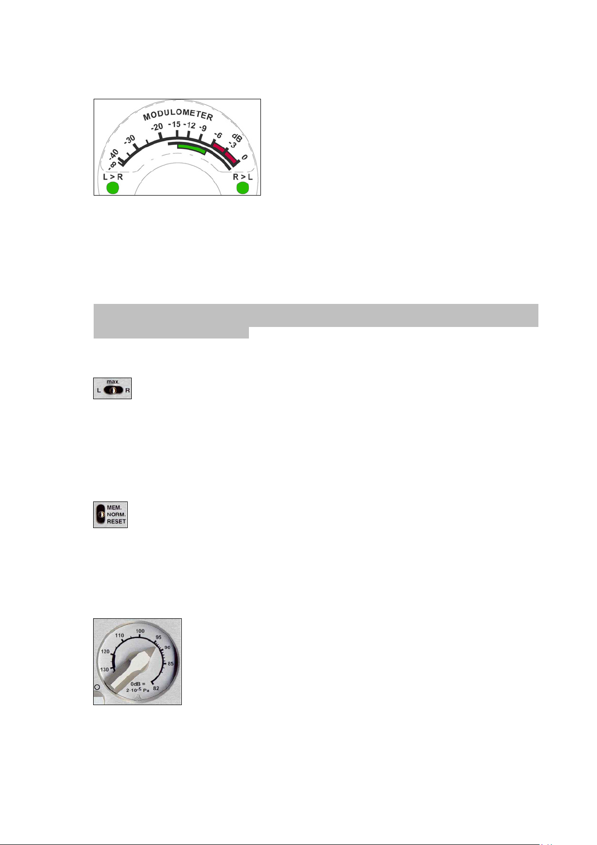
Meter (2)
setting or the Highest when set to the Stereo mode.
The meter scale is calibrated from - to 0 in dB however, if the meter is selected to monitor the input
signal (internal jumpers) and there is an indication above the 0dB point, this means that the A/D
converter will be overloaded. The red area (-6 to 0 dB) is the headroom area. When the BATT switch
is pressed, the green area gives information about the power status. See more information in chapter
4.
The channel being indicated depends on the position of the meter selection switch #3 on machines
fitted with the single pointer version.
Attention: From the box motherboard 9131 300 000 B, when moving the 2 internal jumpers, the
meter can be set before or after the Line Output potentiometer. This can only be done by a Nagra
Service Center. See also chapter 4.
Meter Selection Switch (3)
The NAGRA V can be supplied with either a single or double
pointer modulometer. The double meter is greatly
appreciated in Cinema or two track applications while in
Music or broadcast applications the single pointer instrument
is often preferred. In both cases, the meter is microprocessor
controlled, and has ballistics similar to those of a
modulometer. It can also be used to indicate the condition of
the power source. Fitted with two leds, it will also show the
level of the corresponding channel in the 2 Channel menu
The meter selection switch allows the operator to decide which channel, Left, Right or
MAX, will be displayed on the meter. The MAX position will indicate the highest level
obtained between the two channels and the leds will indicate which channel this corresponds to. From
the box motherboard 9131 300 000 B, the switch will monitor the selected channel in the headphones
in Solo mode (mono). Older boards can be modified to obtain this function. In the case that the
machine is equipped with a double modulometer, the switch #3 does not influence the modulometer
but only the solo selection for the headphones.
Mem / Norm / Reset Switch (4)
This is a three-position switch. In the NORM position the meter will indicate in the normal
manner according to the signal on the input or output (depending on the selection). In the
MEM position the highest obtained level (since the last reset) will be indicated. The reset
position is a snap-switch position and is used to reset the MEM mode. This switch can be moved freely
at any time without affecting the recording. In stereo operation of the machine the function of this
switch is linked to switch #3.
Mike Level Potentiometers (5)
indicates that the input signal is so strong that the microphone pre-amplifiers are overloaded. Above
the 120 dB mark indicating 0 dB on the meter will not cause the input stages to overload but the preamp noise will increase.
These two potentiometers are used to finely control the sensitivity of the
microphone inputs. If the sensitivity selector is set to 0.2 mV/hPa and the level
potentiometer is set to 82 dB (maximum gain) and the modulometer shows 0
dB, this corresponds to an acoustic level of 82 dBspl.
The bold black area on the scale from 120 to 130 dB is an important indication.
If the potentiometer is set inside this area for the meter to indicate 0 dB, it
means that a 100 dB dynamic range is present. If the potentiometer needs to be
adjusted between 130 dB and 150 dB for the meter to indicate 0 dB, then this
Chapter I 6 May 2003
Page 10

Sensitivity Selectors (6)
switches must be set to the corresponding sensitivity. These switches are especially short to avoid
accidental modification and need to be operated with a small screwdriver or pen.
Rotary Lock (7)
Used to lock the two mike pots mechanically together. When the button is in the horizontal
position "" then the two potentiometers are mechanically locked together irrespective of
their individual positions. In the vertical position " " the potentiometers are totally
independent. In order for the button to be moved to the horizontal position it must be slightly
depressed.
LFA / Speech / Flat (8)
+5
+0
d
B
F
S
-5
-10
-15
-20
These two switches are used to select the desired sensitivity of the microphones
connected to the microphone inputs. The possible selections are 1 mV/hPa, 4
mV/hPa and 0.2 mV/hPa. Depending on the type of microphones used, those
This is the filter selection switch. The filters available are the same as those on other
NAGRA models and act on both the microphone and Line Inputs. The corresponding
curves for the filters are shown:
FLAT filter response curve
(Measurement at AES bus output)
-25
-30
20 30k50 100 200 500 1k 2k 5k 10k
+5
+0
d
B
F
S
d
B
F
S
-5
-10
-15
-20
-25
-30
20 30k50 100 200 500 1k 2k 5k 10k
+5
+0
-5
-10
-15
-20
Hz
LFA filter curve
(Measurement at AES bus output)
Hz
Speech filter curve (Measurement
at AES bus output)
-25
-30
20 30k50 100 200 500 1k 2k 5k 10 k
Chapter I 7 Oct 2002
Hz
Page 11
Reference Switch (9)
By pushing the switch upwards, the internal reference generator can be activated. As long as
the switch is held in this position, a sine wave of 1 kHz (at 48/96 kHz, 919 Hz at 44.1/88.2
kHz), will be present at the outputs, if the NAGRA-V is in the test position. When the
reference switch is held in the upper position during record, this signal will be recorded. No indication
is given on the modulometer. While the reference signal is activated, the input signals are muted. The
reference level is factory set to 18 dB.
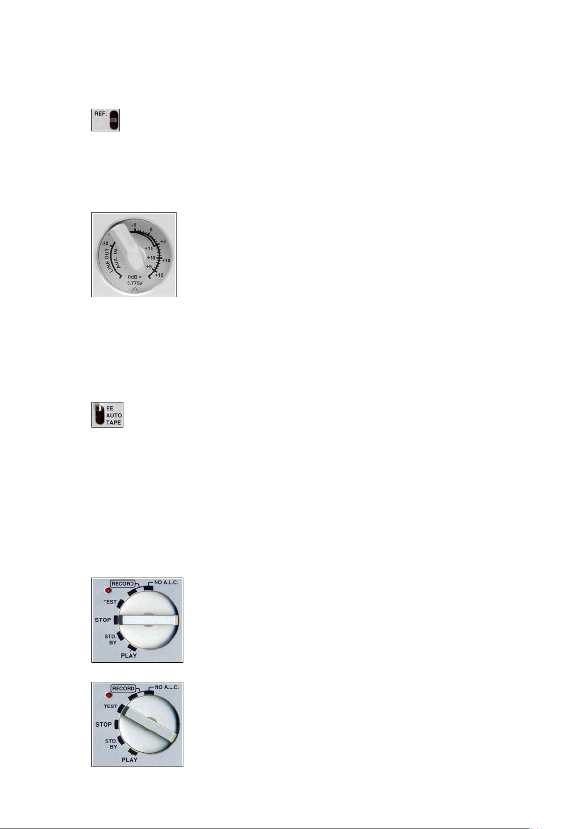
Aux In and Line Out Potentiometer (10)
This potentiometer has two different functions according to the choice made in
the menu mode. If the menu is selected to LINE OUT then this pot will adjust the
Line Output level of both channels simultaneously, as well as the headphone
and loudspeaker level. Its position is memorised by the microprocessor of the
machine. That is to say, if the pot is set to the +6 dB position, then 0dB on the
meter will give a Line Output of 1.55 V or +6 dBm. If the menu is now changed to
use this pot to control the AUX IN input then the initial output setting will be stored
in the memory of the machine and will remain at 1.55V. Once the menu is set to
the AUX IN mode then this pot serves to adjust the level of the AUX Line Input coming from the 15
pole "D" type EXTENSION connector. Equally if the user changes the use of this pot back to LINE
OUT, then the previously set off the AUX IN level will be stored in the memory. These modes can be
reached using a shortcut by pressing the SHIFT key to go rapidly to input or output adjustment
(depending on the settings made in the menus).
EE / Auto / Tape (11)
EE position: Only the input signals will be available at the outputs (EE means Electronic-
Electronic). TAPE position: This position simulates the behaviour of a tape transport. The
output signals are sounds coming from the disk, the input signals when in the record mode
or in test mode, the recorded sounds when playing back, rewinding, etc.... and muted in stop. AUTO
position: This position will automatically select the EE mode or TAPE mode depending on the status
of the transport. Note: When CAM. RET (camera return) is selected, the camera return signal is
available on the speaker and headphones only in TAPE position. Switching between TAPE and AUTO
position is a fast way to select CAM.RET. or LINE OUT as monitoring source
Main Function Selector (12)
The rotary main function selector is the principle-operating switch for the NAGRA-V. It is a six position
rotary selector. Operation of each position is explained below. The present settings of the menus of
the machine will be scrolled through on the front panel display each time the machine is switched ON.
STOP. This is the main OFF position of the machine. None of the circuits of
the machine are powered in this position. When this position is selected the
machine will switch off after a few seconds if in the Power Delay menu,
Manual is not set.
If Manual is selected, the PC will remain operational. To stop the machine in
this mode the SHIFT button should be pressed and held for minimum 2
seconds while the Main selector is set to STOP.
TEST. In this position all the circuits are powered allowing the adjustment of
levels and signal monitoring. This can be considered as a "stand-by before
record" position. All menu verification and settings can be made in this position.
If the PREREC is set to ON, the record led will start blinking, and meaning that
the closed loop recording (into memory) is active.
Chapter I 8 Jan 2003
Page 12
RECORD. The record position, marked RECORD is the standard position
used for recording and the internal limiters (if fitted) NV-LIM #7031 130 000 will
be active and turned on (in the limiter sub-menu). When recording, the red led
beside the main function selector will be alight.
When recording, pressing the grey STOP key will automatically create a new
take number without interruption in the recording process. The position "No
A.L.C." is the position for recording without the internal limiters (if fitted).
STD. BY. In this position the grey push-button switches are activated and will
act for rewind, fast forward, skip then stop in both directions and STOP
features.
Access to all the menus & settings of the machine is also enabled.
Rewind at 80 times nominal speed.
Fast Forward at 80 times nominal speed
Skip back by one take and then STOP. The first time this is pressed it will skip
to the beginning of the current take.
Skip forward by one take and STOP.
STOP during rewind or fast forward.
Shift Key (13)
Menu mode. The SHIFT key must be pressed (and kept pressed) in order to move through the
This is the normal PLAYBACK position. The NAGRA V will go into playback
mode either from where the machine was after the previous play, or from the
beginning of the last recorded take if the machine had previously been in
record mode. Once the play mode has been selected the five grey push-button
switches below the display also become active (see below).
Rewind at four times nominal speed.
Forward at four times nominal speed
Skip back followed by PLAY by one take each time it is pressed.
The first time this is pressed it will skip to the beginning of the current take.
Skip forward followed by PLAY by one take each time it is pressed.
Toggles between Play and Pause.
menus on the LCD display on the front panel of the NAGRA V. When it is pressed
the five grey transport keys operate using their shifted ARROW features. As soon as
the SHIFT key is released then it will act as an ESC and the display will return to the
main display screen chosen. While in the menu mode the STOP key becomes the
EXECUTE function. When the shift key is pressed rapidly twice, it stays in the menu
mode (Flag 1 on the display is on). To remove the menu mode, press the SHIFT
key once again or move the main rotary selector to another position. A full
description of the menus is explained later in this manual.
Chapter I 9 Jan 2003
Page 13
Sync mode. When the shift key is pressed and held while moving the rotary selector to the PLAY
position, the machine turns on the SYNCHRONIZER. The sync mode turns off by
moving the rotary selector.
Power delay. In the case that the POW. DELAY menu is set to MANUAL, press and hold the shift
key while turning the rotary selector to the STOP position. Keep the shift key still
pressed for 2 seconds until the machine turns OFF.
Speaker. Turning ON, OFF or selecting AUTO switching the speaker without going into the
menus, can be made by keeping the shift key pressed while pushing the BATT
switch. Every time this function is executed, it will scroll on the display through the 3
different possibilities.
In/Out pot. This give access to the mode of operation of the third potentiometer on the front
panel of the machine (AUX IN & LINE OUT) in the case that in the menu, the line
potentiometer of the NAGRA V is set to the POT.SHIFT position. That is to say that it
will adjust the input signal if the SHIFT key is kept pressed and it will adjust the
OUTPUT signal if the SHIFT key is not pressed.
Recall 1 Shortcut: When the shift key is pressed and also the left arrow key, the template
recall menus are immediately displayed.
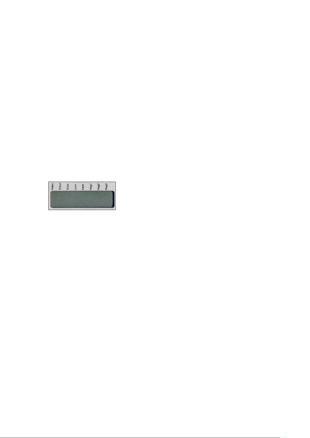
LCD Display (14)
This is a 14 segment 8 digit back lit LCD display, permitting alphanumeric indication of a large quantity of different information and
allowing internal settings of the machine to be made in the MENU
mode. In normal operation it will indicate the current take number and
time from the beginning of it. It is also used to display the internal
STATUS of the machine, remaining time available on the cartridge to be recorded etc. The display will
be illuminated if the illumination switch # 1 is put in the "cloud" position.
It can be used to display the following:
Menu Tree
Take Number and time from start of take
Remaining Time on the cartridge/HDD (related to bit & sampling rates)
Time Code
Error codes
Flags on top of the display:
Video If a valid video versus TC format is connected
Tcext If external time code is present
Tcint If during playback the time code is accurate
Lock If the machine is locked in chase mode
PWR If the batt. or ext. voltage drops below limit
Flag 1 If the SHIFT button was pressed twice (menu lock)
Flag 2 Not used
Flag 3 Not used
Chapter I 10 Jan 2003
Page 14
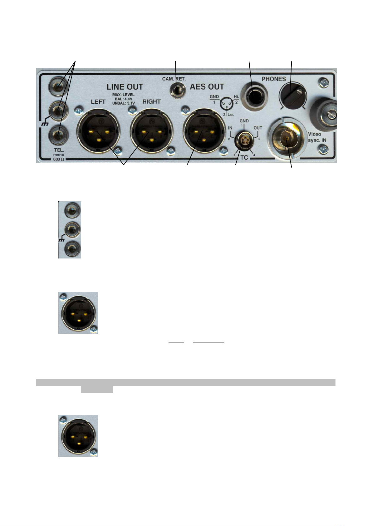
RIGHT SIDE PANEL
1
Banana Output Connectors (1)
This is the telephone output connection. It is a mono output fitted with a transformer with
output impedance of 600 from 300 Hz to 5 kHz, and is used for connection to a standard
switched telephone line. The output level of this connection can be selected in the TEL
LEVEL position of the menu mode to be either 1.55V or 4.4V. When in operation, the return
feed from the telephone can be heard in the headphones or on the internal loudspeaker if
selected.
8
2 3
4 5
67
Line Output Connectors (2)
These two 3 pole XLR female connectors are the standard analog audio
transformer-less outputs. The level of which can be controlled by the Line Output
potentiometer on the front panel (providing it has been previously selected). The
nominal output level on these connectors is 1.55V for 0 dB on the meter.
Pin # Connection
1 Ground
2 Audio signal High
3 Audio signal Low
WARNING: Be sure not to connect these outputs to a mixer supplying 48V phantom as this will damage
the outputs.
AES Output Connector (3)
The 3 pole male XLR AES output connector is a digital output corresponding to the
format of the AES bus used throughout the professional audio industry. The
resolution is of 16 bits or 24 bits depending of the output settings. This connection
allows direct connection to any other digital equipment equipped with an AES
interface
Chapter I 11 May 2002
Page 15
Headphone Output Jack (4)
This is a standard ¼" Stereo Jack connector. The level of the headphone output can be
adjusted using the headphone level control. When the NAGRA-V is connected to a
standard telephone line the return feed of the line is always available in the headphones.
The output pot will also affect the headphone level.
Headphone and Speaker Level Control (5)
Rotary volume control for the headphones. This potentiometer acts as if it is in series with
the output level potentiometer.
External Sync. or Video Input (6)
If the NAGRA-V is fitted with the internal Time Code option then this is the connector
where a video signal (PAL, NTSC, NTSC B/W, 75 Ohms internally loaded) or an
external work clock can be imported. The external sync input is yet another way to
synchronise the internal clocks of the NAGRA-V. The advantage of this 5V logic input is
that it can be used to control the VCXO (Voltage Controlled Crystal Oscillator) from an
external source. The input can be 44.1 kHz, 48 kHz, 88.2 kHz or 96 kHz with a logic voltage level
from min. 0.5 V to 5.0 V. This signal can be fed to the machine through the BNC connector.
Operation of the Time Code is covered in detail in CHAPTER 3 of this manual.
Time Code In/Out Lemo Connector (7)
The time code input and output is located on a 5 pole LEMO connector, the pinning of
which corresponds to that of the IV-STC, the NAGRA-D and T-Audio-TC. The time code
system of the NAGRA-V is more versatile than that of the IV-STC or NAGRA T-Audio. It
offers possibilities that were not previously available and also requires care on the part of
the operator to ensure that the correct information is being recorded and displayed at all
times.
Operation of the Time Code is covered in detail in CHAPTER 3 of this manual.
(QCTCU cable # 7016909000 LEMO to open-ended TC cable)
Camera Monitor Return (8)
This input can be used to return the audio signal from a camera to the headphones (or
speaker) of the Nagra-V. If in the menu CAMERA RETURN is set, the selection between
the return signal or the Nagra-V inputs or playback signals is made by the EE/AUTO/TAPE
selector. In the TAPE position, only the camera return signal goes to the speaker (headphones). This
return signal can not be recorded on the disk.
The return level can only be adjusted via the menu settings. See chapter 2.
Note: Early Nagra-Vs have MON. instead off CAM. RET.printed on the panel
Chapter I 12 May 2002
Page 16
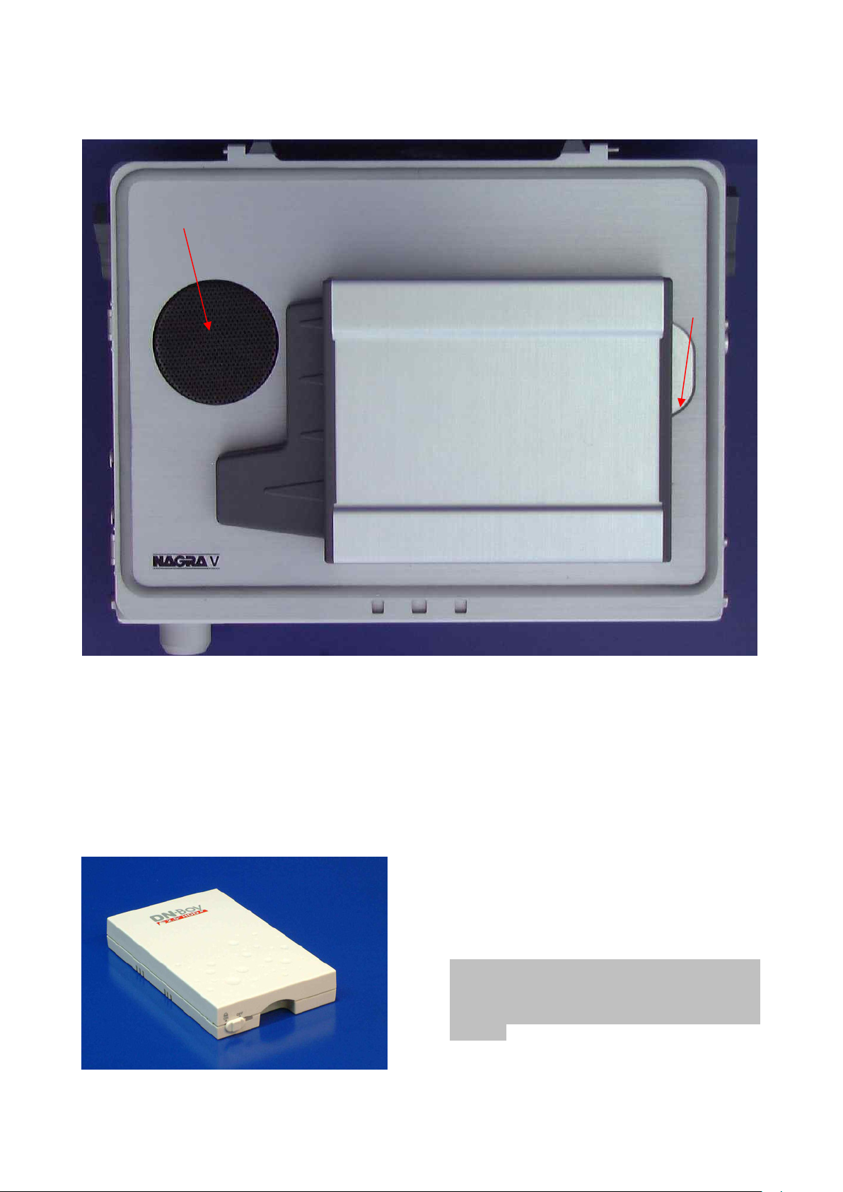
TOP DECK
1
2
Internal Speaker (1)
This small built-in loudspeaker can be used to listen to the recordings. The Line Out level
potentiometer controls the volume of the internal loudspeaker on the front panel of the machine and
in conjunction with the headphone level pot. The speaker can be switched ON, OFF or AUTOMATIC
in the menu mode or with the combination of the SHIFT button & the BATT switch.
Front of the HDD drawer (2)
A little switch permits the powering of the HDD
drawer. In the power on position, on the left side of
the drawer, a little bracket will appear and locks it
mechannically inside the carrying bay of the
Nagra-V.
Attention: Never remove or insert the HDD from
a Nagra-V if it is in the power on mode. Always
shut down the machine, change the drive, put the
power swicth on the drawer to on and turn on the
Nagra-V.
Chapter I 13 May 2003
Page 17

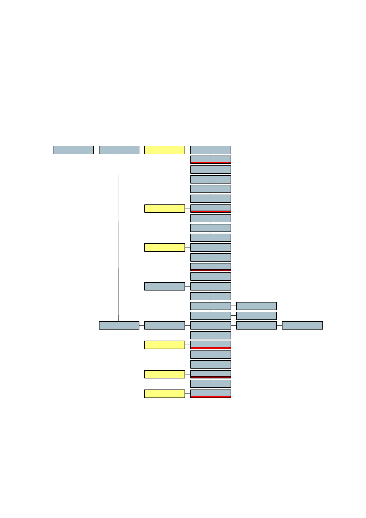
CHAPTER 2
MENU STRUCTURE AND USE
MENU MODE.................................................................................................................................... 3
GENERAL STRUCTURE OF THE MENUS.................................................................................... 3
NAVIGATION THROUGH THE MENUS......................................................................................... 3
DISPLAYING AND ACTIVATING MENUS...................................................................................... 3
SCROLLING THROUGH THE SETTINGS ..................................................................................... 3
TREE ................................................................................................................................................ 4
MENU SHORTCUTS ..................................................................................................................... 7
Template shortcut....................................................................................................................... 7
Sc / Tk shortcut........................................................................................................................... 7
Reset TC.................................................................................................................................... 7
Speaker On, Off, Automatic ........................................................................................................ 7
Go to mark ................................................................................................................................. 7
Battery selection forced to OTHER ............................................................................................. 7
DISPLAY SELECTION................................................................................................................... 8
Index .......................................................................................................................................... 8
Remain....................................................................................................................................... 8
Sc & Tk ...................................................................................................................................... 8
Time Code.................................................................................................................................. 8
TC Delta..................................................................................................................................... 8
Display 2........................................................................................................................................ 8
TIME CODE SELECTION .............................................................................................................. 9
Gen ............................................................................................................................................ 9
Format...................................................................................................................................... 10
Rec SRC .................................................................................................................................. 10
User Mode................................................................................................................................ 10
Set Gen.................................................................................................................................... 11
Sync......................................................................................................................................... 11
Offset ....................................................................................................................................... 11
Chase Ref ................................................................................................................................ 11
Syncmode ................................................................................................................................ 12
Fix Clk ................................................................................................................................................ 12
Var Clk................................................................................................................................................12
Reactime.................................................................................................................................. 12
DIRECTORY MENU .................................................................................................................... 13
PLAY........................................................................................................................................ 13
COPY....................................................................................................................................... 13
FOLDERS. ...................................................................................................................................... 14
WORKING FOLDER.................................................................................................................... 14
CHANGING WORKING FOLDER. ............................................................................................... 15
NEW FOLDER............................................................................................................................. 15
RENAMING A FOLDER. .............................................................................................................. 15
DELETING / ERASING A FOLDER.............................................................................................. 16
DELETING / ERASING AN ENTIRE DISK.................................................................................... 16
DISK FREE SPACE AND DISK CAPACITY. ................................................................................ 16
TWIN-DRIVE................................................................................................................................... 17
WORKING DRIVE........................................................................................................................ 17
CHANGE WORKING DRIVE........................................................................................................ 17
COPY FUNCTION........................................................................................................................... 18
HOW THE COPY WORKS........................................................................................................... 18
COPYING ONE OR SEVERAL INDEXES.................................................................................... 18
COPYING A FOLDER.................................................................................................................. 19
AUTOMATIC COPYING............................................................................................................... 19
Chapter 2 1 March 2005
Page 18

COPY ERROR............................................................................................................................. 19
COPY STATUS............................................................................................................................ 19
OPERATIONAL MESSAGES....................................................................................................... 19
Idle ........................................................................................................................................... 19
Copying.................................................................................................................................... 19
Suspend................................................................................................................................... 20
Aborting.................................................................................................................................... 20
COPY ERROR MESSAGES ........................................................................................................ 20
DiskFull .................................................................................................................................... 20
ExistErr..................................................................................................................................... 20
Pow. Lost ................................................................................................................................. 20
Fold. Err. .................................................................................................................................. 20
Read Err................................................................................................................................... 20
WriteErr.................................................................................................................................... 20
Open Err................................................................................................................................... 20
NotFound. ................................................................................................................................ 20
Del.Err...................................................................................................................................... 20
WHAT TO DO IN CASE OF AN ERROR...................................................................................... 20
RETRY..................................................................................................................................... 21
ABORT..................................................................................................................................... 21
SKIP......................................................................................................................................... 21
SKIP ALL.................................................................................................................................. 21
OVERWRITE............................................................................................................................ 21
OVERW.ALL ............................................................................................................................ 21
RETRIEVE ............................................................................................................................... 21
SOLUTIONS TO DIFFERENT PROBLEMS DURING COPY........................................................ 21
Solutions in case of Disk Full .................................................................................................... 21
Solutions in case of Exist Err .................................................................................................... 21
Solution in case of Pow. Lost.................................................................................................... 22
Solution in case of Fold. Err...................................................................................................... 22
Solution in case of Read Err. .................................................................................................... 22
Solution in case of WriteErr....................................................................................................... 22
Solution in case of Open Err. .................................................................................................... 22
Solution in case of Not Found................................................................................................... 22
Solution in case of Del. Err........................................................................................................ 22
COPY LIST.................................................................................................................................. 23
ABORT ALL MENU...................................................................................................................... 23
STOPPING A COPY.................................................................................................................... 23
COPY AND POWER OFF............................................................................................................ 23
OTHER ERROR MESSAGES...................................................................................................... 24
Copying.................................................................................................................................... 24
List Full..................................................................................................................................... 24
In Use....................................................................................................................................... 24
Copy Err................................................................................................................................... 24
MONITOR MENU ........................................................................................................................ 25
MODULOMETER MENU ............................................................................................................. 26
BATTERY RESERVE DISPLAY................................................................................................... 26
TITLING....................................................................................................................................... 27
CUE............................................................................................................................................. 27
TEMPLATE MENU....................................................................................................................... 28
REFERENCE FREQUENCY SELECTION................................................................................... 28
SAMPLING FREQUENCY SELECTION....................................................................................... 29
FORMAT MENU .......................................................................................................................... 29
INPUT MENU .............................................................................................................................. 30
OUTPUT MENU........................................................................................................................... 31
LINE POTENTIOMETER MENU .................................................................................................. 31
PRE-RECORD MENU.................................................................................................................. 32
DISK MENU................................................................................................................................. 34
REEL NB. MENU......................................................................................................................... 34
OTHER SETTINGS...................................................................................................................... 35
Chapter 2 2 March 2005
Page 19
MENU MODE
Power
GENERAL STRUCTURE OF THE MENUS
The NAGRA V incorporates a system of menus similar to the "tree" of directories and subdirectories on the hard disk of a PC. The functions that are available via the menu mode are
in principle settings of the NAGRA V rather than operations that need to be done frequently
during normal use of the machine in the field. Menu viewing and modification is made using
shift + the grey push-button keys located on the front panel, and the 8 digit LCD display.
In this manual, all terms referring to MENUS will be written in BOLD ITALIC PRINT. For
example: select MANUAL in the Pow. Delay menu.
NAVIGATION THROUGH THE MENUS
To move up
To move down
Navigation through the menus is relatively straightforward.
There are 22 principal menus, each of which has its submenus, which will be explained below.
The SHIFT key needs to be
Video
TCExt
TCInt
Lock
Flag 1
held down to navigate through
Flag 3
Flag 2
the menus. If it is pressed
000 000
.
.
twice in quick succession then
EXE
Folder_A
To move left
To move right
To execute a menu
Stored in template
Default settings
after SET LOST
Sample text
the FLAG 1 comma will light
on the display to indicate that the shift key is locked on and need
EXE
not be held down. Pressing the shift key again or moving the main
function selector will release it. Once the menu is displayed,
navigation through the menus is made by using the transport keys combined with the signs
above the keys.
When the user accesses a menu position using the right arrow key, the display will indicate
the currently selected setting / value. To choose an alternative, simply display the desired
choice using the UP / DOWN arrow keys, and press the EXE key to confirm the selection.
Note:
EXE
means press the EXE key. All text in blue print i.e.
2.40 GB C*2.40 GB C*Folder_A
must be
considerated as sample text.
DISPLAYING AND ACTIVATING MENUS
Menus written in CAPITAL letters may be executed. All menus written in lower case
characters (or a mix of upper and lower case) are menu tree positions that are not
executable. Example: The Template cannot be executed, but the RECALL X can be
executed. When the EXE key has been pressed a "beep" will be heard (either on the speaker
or on the headphones depending on the present setting of the beep function) to indicate that
the selection has been correctly accepted and executed.
If the display remains on the selected choice after EXE has been pressed, this indicates that
the feature has NOT been executed for some reason. This could be because it is not an
executable function or that the machine will not allow it to be selected due to other settings.
SCROLLING THROUGH THE SETTINGS
Pushing down the BAT switch briefly will scroll through the current menu settings of the
machine. If the BAT selector is briefly pushed down twice then the time code and
synchroniser settings will be shown assuming the machine is equipped with the internal time
code option.
Chapter 2 3 March 2005
Page 20
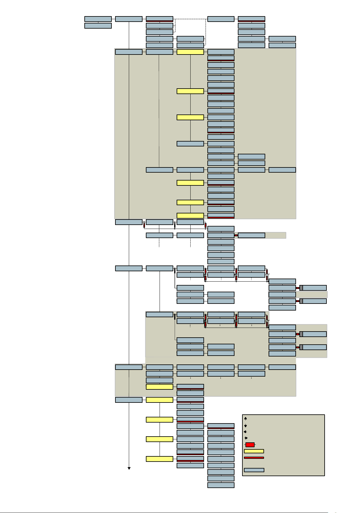
Template
Sc / Tk
TREE
Software version
V3.10
000 00.00 INDEX
REMAIN
SC & TK SC & TK
TIMECODE
DELTA TC
TimeCode Gen
TIME
USER
Format
Rec. Src. INT. GEN
User Mode
Set Gen. FROM EXT.
Chase Ref.
Sync. Mode
Folder_2 A* 22 Fil. B* 2.40 GB C*
Folder_2 A* 22 Fil. B* 2.40 GB C*
Dir 001. 3.22 48K / 24
E
E
E
X
X
X
E
E
E
E
E
E
X
X
X
E
E
E
44K1 / 16002. 5.48
Folders Ext. Drive
Int. Drive
Int. Drive
Int. Drive
Folder_1 A* 16 Fil. B* 1.50 GB C*
Folder_1 A* 16 Fil. B* 1.50 GB C*
Folder_C 18 Fil. 1.90 GB
E
E
E
X
X
X
E
E
E
Folder_2 A* 22 Fil. B* 2.40 GB C*
Folder_2 A* 22 Fil. B* 2.40 GB C*
Folder_D 26 Fil. 2.80 GB
SELECT
SELECT
SELECT
CAPACITY
CAPACITY
CAPACITY
FREE SPACE
FREE SPACE
FREE SPACE
Folder_1 A* 16 Fil. B* 1.50 GB C*
Folder_1 A* 16 Fil. B* 1.50 GB C*
Folder_A 16 Fil. 1.50 GB
E
E
E
X
X
X
E
E
E
Folder_2 A* 22 Fil. B* 2.40 GB C*
Folder_2 A* 22 Fil. B* 2.40 GB C*
Folder_B 22 Fil. 2.40 GB
SELECT
SELECT
SELECT
CAPACITY
CAPACITY
CAPACITY
FREE SPACE
FREE SPACE
FREE SPACE
Display 2 INDEX
REMAIN
TIMECODE
DELTA TC
24 FPS
25 FPS
29.97 DF
29.97 FF
30 DF
30 FF
JAM SYNC.
EXTERNAL
ASSEMBLE
DATE
DATE INC.
FREE
FREE INC.
RESET TC
Set Time
00.00.00.00
Set User 00.00.00.00
Set + H00 M00 + S00F00.00OffsetSync
RESET
TC EXT.
TC INC.
VIDEO
FIX. CLK.
VAR. CLK.
015 FRAMReac. time
E
E
E
X
X
X
E
E
E
SELECT
SELECT
PLAY
COPY
EXE
COPYCOPYC 001 -- 006
DELETE
DEL. TO END
RENUMBER
REN. ALL
E
E
E
X
X
X
E
E
E
E
E
E
X
X
X
E
E
E
55.87 GB D*
55.87 GB D*
55.87 GB
51.97 GB D*
51.97 GB D*
51.97 GB
E
E
E
X
X
X
E
E
E
E
E
E
X
X
X
E
E
E
55.87 GB D*
55.87 GB D*
55.87 GB
51.97 GB D*
51.97 GB D*
51.17 GB
E
E
E
X
X
X
E
E
E
E
E
E
X
X
X
E
E
E
E
E
E
X
X
X
E
E
E
E
E
E
X
X
X
E
E
E
Twin Option
TIME
USER
TC Option
Twin Option
E
E
E
X
X
X
E
E
E
E
E
E
X
X
X
E
E
E
SELECT
SELECT
SELECT
COPY
COPY
NEW
NEW
NEW
COPY
RENAME
RENAME
RENAME
ERASE
ERASE
ERASE
E
E
E
X
X
X
E
E
E
E
E
E
X
X
X
E
E
E
SELECT
SELECT
SELECT
COPY
COPY
NEW
NEW
NEW
COPY
RENAME
RENAME
RENAME
ERASE
ERASE
ERASE
EXE
16 Index D*16 Index D*
A
Twin Option
EXE
A
16 Index D*16 Index D*
EXE
A
16 Index D*16 Index D*
EXE
A
16 Index D*16 Index D*
Copy Status
Copy list
16 Index D*16 Index D*Copying 16 Index D*16 Index D*Int. Drive 16 Index D*16 Index D*Folder_A 55.87 GB D*55.87 GB D*Index 001
16 Index D*16 Index D*1 - Int. 16 Index D*16 Index D*Folder_A 16 Index D*16 Index D*001 - 999
ABORT ALL
Autocopy OFF
ON
Monitor
STEREOMode
MONO
TOGGLE
Source
Loud. Spk.
Beep
LINE OUT
CAM. RET. 0 DB
TEL.
SPK. ON
SPK. OFF
SPK. AUTO
ON
OFF
+ 2 DB
+ 4 DB
+ 6 DB
- 12 DB
- 10 DB
- 8 DB
- 6 DB
EXE
Folder_A
To move up
To move down
To move left
To move right
To execute a menu
Stored in template
Default settings
after SET LOST
Sample text
- 4 DB
- 2 DB
Chapter 2 4 March 2005
Page 21
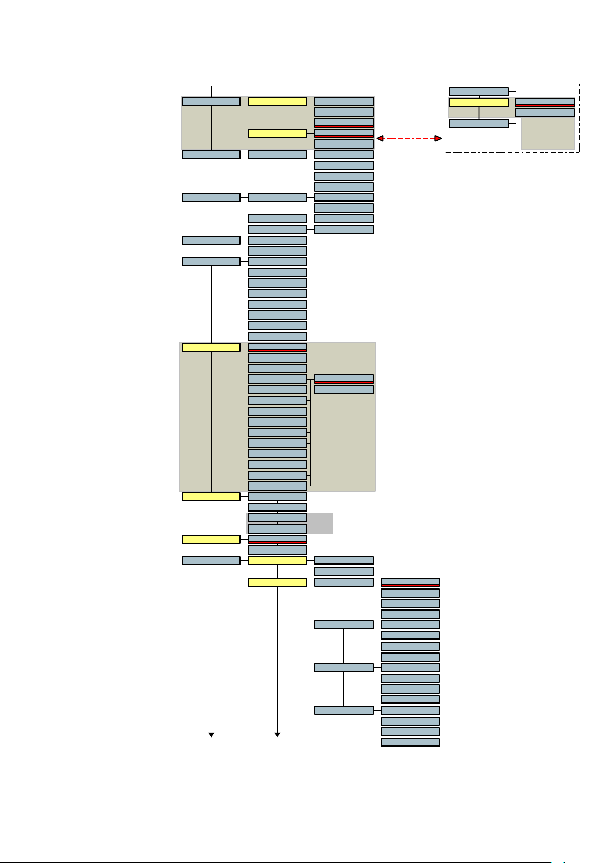
* A p p ea rs if th e
m od u lo m et er is se t
b eh in d t he o ut pu t
p ote n tio m e te r
S ee a ls o * *
M o d u . L e d
R E S E TB a t. X .X X
M o d eT it li n g
S ce n e
M o d eT a k e
S ou rc eM o du lo m .
C u e
M A R K
G O TO M A R K
R E C A L L 1T em p l a t e
R E C A L L 2
R E C A L L 3
R E C A L L 4
S TO R E 1
S TO R E 2
S TO R E 3
S TO R E 4
M A ST E RR ef. F re q.
M A S. + 0. 1%
M A S. - 0 .1 %
A E S 4 4. 1
A E S 4 8
A E S 8 8. 2
A E S 9 6
P A L
N TS C
N TS C 6 0
W C K 4 4 .1
W C K 4 8
W C K 8 8 .2
W C K 9 6
S a m . F re q. 4 4 .1 K H Z
4 8 K H Z
8 8. 2 K H Z
9 6 K H Z
F o rm a t
B W F 24
B W F 16
S ou rc eIn p u t A N AL O G
L E V . I N
L E V . O U T
L E V . A U T O
S TE R E O
2 C H .
L I . I O N
N I- C D / M H
D R Y C E LL S
O T H E R
O F F
O N
S c. _ _ _ _ 1
T k . 0 1
C R YS T A L
V C OV C O
T C O pt ion
N V- 96 K
O p tio n
A E S
M ik e L.M a t ri x L EF T
M ik e R . L EF T
A u x . L . L E F T
A u x . R . L E FT
R IG H T
B O T H
O F F
R IG H T
B O T H
O F F
R IG H T
B O T H
O F F
R IG H T
B O T H
O F F
M o n ito r
M o d u. L e d
B at . X . X X
S TE R E O
2 C H .
** A pp e ar s i f t he
m od u lo m et er is se t
b efo re t he o ut pu t
p ote n tio m e te r
S ee a ls o *
Chapter 2 5 March 2005
Page 22
Disk
OFFMike Lim.
Limiter Option
LEFT
RIGHT
BOTH
24 BITSW. LengthOutput
16B. DITH
MS Dec. OFF
ON Mid. Gain 0 DB
POT. OUTLine Pot.
POT. IN
POT. IN - L
POT. IN - R
POT. OUT + S
POT. IN + S
POT. OFF
OFFPrerec.
ON 1 SEC.
3 SEC.
5 SEC.
10 SEC.
15 SEC.
20 SEC.
OFFAuto Rec.
ON
Threshld
Trig. Dly 0.0 SEC
Stop Dly NONSTOP
Ext. DriveReformat
Twin Option
Int. Drive
ModeReel Nb. ON
OFF
Current Curr. XXX
Next Next XXX
TimeDate TimeOther T XX.XX.XX
Pow. Delay
MANUAL
2 SEC
5 SEC
PTT lev.
4.4 VOLT
1.55 VOLT
Software
V X.XX
DD-MM-YY
RESET
-1 DB
-2 DB
-3 DB
-4 DB
-5 DB
-6 DB
Side Gain 0 DB
-1 DB
-2 DB
-3 DB
-4 DB
-5 DB
-6 DB
-6 dB
-12 dB
-18 dB
-24 dB
-30 dB
-36 dB
0.1 SEC
0.3 SEC
1.0 SEC
5 SEC
15 SEC
30 SEC
1 MIN
2 MIN
5 MIN
15 MIN
FAT 32
FAT 16
FAT 32
FAT 16
XX.XX.20XXDate
DV V X.XX TC V X.XX
Chapter 2 6 March 2005
Page 23
MENU SHORTCUTS
000 00.00Template
Sc / Tk
Pressing the left arrow key, from the main display position, will give immediately access to the
Template menu or the Sc / Tk menu.
Template shortcut
RECALL 1Template
RECALL 2
From this position moving to the right will go directly to RECALL X menus. See also the
Template paragraph.
Sc / Tk shortcut
Sc / TkMode Tk. 01Sc. _ _ _ _1
From the main display, move left (Template) and then down to access the Sc / Tk menu.
Moving left or right from here gives access to the Scene or Take number respectively.
Once attempted the Sc or Tk menu, the first digit starts flashing. Pressing the up arrow key
gives directly access to number selection. Pressing the down arrow key gives directly access
to character selection.
Note: If a Sc / Tk name, number is entered using the spaces, once executed, they will
disappear. Example: Entering for Sc A_12_ and execute will show afterwards A12.
Reset TC
Moving to the Time Code menu and pressing the EXE key selects automatically the RESET
TC. Once RESET TC. Is on the display, press again the EXE key to reset.
Speaker On, Off, Automatic
By holding the SHIFT key and pressing the BATT. switch will change the status of the
speaker.
Go to mark
From the main display, hold the SHIFT key and press the EXE key returns to the mark
position of the index.
Battery selection forced to OTHER
Hold the BATT. switch an turn on the machine.
This solution can be used in the case that the machine doesnt switch due to the voltage level
of the battery or external power. The machine ignores the settings in the Bat. X.XX menu and
automatically selects the OTHER position which gives the largest possible voltage range.
Switching off an on again (without pressing the BATT. switch) selects again the standard
setting.
Chapter 2 7 March 2005
Page 24

DISPLAY SELECTION
This is the first line of the status display, and will always indicate the pre-selected mode.
Moving to the right and scrolling, the user can see and select the different display modes
possible. This selection is automatically displayed when the machine is switched on or after a
scrolling of the selected settings has been completed. The possible selections are INDEX,
REMAIN, SC & TK, TIMECODE, and TC DELTA (the TC displays are only available if NV-TC
option is installed).
000 00.00 INDEX
REMAIN
SC & TK SC & TK
TIMECODE
DELTA TC
Index
When this position is selected, the display will indicate the current index
number followed by the time from the beginning of the present index, which is
indicated in h.mm.ss. The index number will automatically be incremented by
"1" each time the machine is put into record mode. This display can be used
when the machine is in all operational modes. The index number may be
incremented without coming out of record by simply pressing the EXE key
during the recording to create a new index number.
Remain
This indicates, in hours and minutes, the remaining recording time available
on the HDD according to the current settings of the machine (Sampling
frequency, bit rate etc).
Sc & Tk
When Titling is turned on, the Scene and Take naming are automatically
added in the Meta-Data of the recorded file. Every time a new record is made,
the Tk will increment by 1. If during record, the EXE key is pressed this to
start immediately a new record, the Tk will not be incremented. This is in the
case that the previous recording was considered as a false start.
Once attempted the Sc or Tk menu, the first digit starts flashing. Pressing the
up arrow key gives directly access to number selection. Pressing the down
arrow key gives directly access to character selection.
TIME
USER
Display 2 INDEX
REMAIN
TIMECODE
DELTA TC
TIME
USER
Time Code
This gives access to the time code displays (only if the machine is fitted with
the NV-TC option). When moving to the right from this display, the time or
user portion can be chosen for display.
TC Delta
This is the dynamic difference between the external time code reference and
the time code of an index while the machine is in the chase synchronise
mode.
Display 2
The second display section allows the user to program alternative display
information that can be briefly accessed each time the "SHIFT" key is
pressed. For example if INDEX is the standard display, the remaining time
may be briefly seen at any time. Releasing the "SHIFT" key returns to the
initial display.
Chapter 2 8 March 2005
Page 25
TIME CODE SELECTION
(The Time code menus display will only be indicated if the machine is fitted with the NV-TC
time code option # 70 31120 000)
This menu allows the access and setting of all the time code options of the machine. It
permits the setting of the internal time code generator, for both TIME and USER data, as well
as frame rate selection and the time code mode. It also allows the choice of the time code to
be recorded, as well as access to the internal time code synchroniser features, including
modes of operation as well as external references to be used.
The currently selected time code menu settings can be seen on the display by pressing the
BAT switch twice in quick succession.
TimeCode Gen Format 24 FPS
25 FPS
29.97 DF
29.97 FF
30 DF
30 FF
Rec. Src. INT. GEN
JAM SYNC.
EXTERNAL
ASSEMBLE
User Mode
Set Gen. FROM EXT.
Chase Ref.
Sync. Mode
DATE
DATE INC.
FREE
FREE INC.
RESET TC
Set Time
Set User 00.00.00.00
Set + H00 M00 + S00F00.00OffsetSync
RESET
TC EXT.
TC INC.
VIDEO
FIX. CLK.
VAR. CLK.
015 FRAMReac. time
00.00.00.00
Gen
When the right arrow is pressed from the TIMECODE position, access is
given to all the internal generator features. Hence "in-the-field" access to
setting of all features concerning the internal time code generator.
If the down arrow is pressed from this point, the display will change to SYNC,
which allows access to all the settings of the internal time code synchroniser.
Pressing the right arrow from the GEN position will move to FORMAT
allowing all the different operating modes and features of the internal
generator to be set.
Chapter 2 9 March 2005
Page 26

Format
Rec SRC
When the right arrow is pressed from the Gen. position the operator can
select the frame rate of the internal time code generator. The internal time
code generator can generate all presently used formats i.e. 24, 25, 29.97 and
30 (the latter two either with or without drop frame). The first value indicated
is the presently selected choice. The default value, automatically selected if
the memory has been lost, is 25 frames per second.
If the down arrow is pressed from the Format position the display will show
Rec.Src. This is the source selection for the time code to be recorded on the
disk. It can be set between INTERNAL, JAM SYNC, EXTERNAL or
ASSEMBLE. If set to the external position, then a longitudinal SMPTE/EBU
time code must be fed to the time code LEMO connector on the right side of
the machine in order to be recorded. The TC.EXT. flag will light on the
display as soon as an external time code is present on this connector.
If INTERNAL is selected then the internal time code generator of the
machine will be recorded.
In the JAM SYNC position, the internal time code generator of the NAGRA V
will automatically be set as soon as a valid time code is connected to the time
code input connector. If the cable providing the external time code signal is
left connected to the machine, a new jam sync will be performed
automatically as soon as the machine detects a difference between the
internal time code generator and the external signal of more than 2 ms. In
order for the jam sync function to operate when the cable is connected,
certain conditions are verified before the set is made. The incoming TC must
be at the correct speed (± 1%) for 10 consecutive frames. Frozen or reverse
time code will prevent a jam of the generator from occurring.
User Mode
If ASSEMBLE is selected each time the machine is put into REC mode a full
time code assemble will be performed. This is done by calculating the time
code value of the last frame of the previous index (taking into account the
sampling frequency) and using the next consecutive frame number as the
time stamp for the beginning of the next index. There will be no time code
discontinuity between indexes.
This menu selects the operating mode of the user bits portion of the time
code generator.
The possible modes can be either, date mode or free mode. In the DATE
position, the date in the DD.MM.YY.xx format must be used. The date will be
automatically updated at midnight (except when running 29.97 non-drop or
30 drop frame).
In the FREE mode, each digit of the user bits can be any value in
hexadecimal (0 to F).
Both of these modes also have an INC (Increment) feature meaning that the
last two right-most positions (xx) will automatically be increased by "1" each
time a new index is made in record, starting from 00 up to a maximum value
of 99.
Chapter 2 10 March 2005
Page 27

Set Gen
Sync
This sub-menu gives access to the value of the internal time code generator.
FROM EXT indicates that the internal generator will be set from the external
time code on the LEMO connector, if the "EXE" key is pressed. From this
position pressing the down arrow will indicate RESET TC which will reset the
time portion of the time code system to zero, and will put the current date of
the internal clock into the user bits. If the user bits are in the free mode then
they will not be altered by the reset function. In the SET TIME menu, if the
right arrow is pressed the display will indicate 00.00.00.00 and the left most
digit will flash. Pressing the arrow keys modifies of the values of each digit as
required. Press EXE to store the new values into generator. The SET USER
position accesses the values of the user bits to be set in the same manner as
for the time code. If the generator is in the date mode then the numbers
entered must correspond to the DD.MM.YY.xx format. If they are in the FREE
mode then any value from 0 to F (hex) can be entered in each position.
If the Rec Src. menu is set to the ASSEMBLE position, then the Set Gen.
command will allow the time code recording to start from a given value once
the recording is started. It will effectively inhibit the assemble command for
the next recording.
This gives access to the selections affecting the internal time code chase
synchroniser of the NAGRA V. The synchroniser is activated by pressing the
SHIFT key while moving the main function selector to the play position. Be
sure that an external reference is supplied.
Offset
Chase Ref
The Offset position allows the operator to have access to the time code
offset between the "off disk" time code and the time code reference. If the
right arrow is pressed then the display will show Set meaning that the
operator has the possibility to press the right arrow again and set the offset in
hours and minutes, and then automatically the seconds, frames and bits
afterwards. This has to be done on two different display screens as there are
only eight digits and it is not possible to indicate the hours portion and the bits
of offset at the same time. Once the offset has been set, if the "EXE" key is
pressed it will be stored in the offset register. Any offset stored in the memory
of the machine will be lost as soon as the machine is powered OFF.
The RESET command will remove any previously stored offset from the
memory.
The Chase ReF. selects of the manner of synchronisation of the NAGRA V.
In the normal SYNC mode (Shift while selecting PLAY on the main selector)
the time code coming from the HDD corresponds exactly to that of the
external reference.
TC INC (incremental) means that there is an unknown time code offset
between the external reference and the time code coming from the disk.
When the machine is put into the TC INC mode the offset between the two
time codes at that exact moment is stored in the offset register automatically.
The final possibility is the VIDEO selection. In this mode the machine will lock
the time code from the HDD to the external video signal on the BNC
connector on the side of the machine.
Chapter 2 11 March 2005
Page 28

Syncmode
Fix Clk
Var Clk
The NAGRA V has two possible clock references that affect the operation of
the synchroniser.
In the FIX CLK mode the machine will always follow the external reference.
Once the machine is in the LOCKED state the internal synchroniser will no
longer influence the transport and the transport speed is controlled entirely by
the reference frequency (REF FREQ menu). If however the synchroniser of
the NAGRA V sees an error of more than 1 frame, it will re-engage itself to
correct the synchronisation error. This is the recommended operating
mode.
This mode is designed to allow the machine, using the internal synchroniser,
to follow an external reference that is not the same as the reference
frequency selected in the menu. This setting allows the internal synchroniser
to modify the internal clocks in such a way as to follow this reference (for
example NTSC / NTSC 60). In this mode the digital output is not available
and the quality of the analogue outputs may be slightly degraded. Such a
situation arises when the recording has 30FF time code and the external
reference is NTSC (59.94). The machine will slow down to 29.97 FPS. There
will be an increase in jitter in the clocks in this mode, and should be avoided
unless absolutely necessary.
Reactime
This feature gives access to the reaction time of the internal synchroniser.
This is the number of incorrect consecutive frames that will be accepted
during the SYNC mode before the NAGRA V will drop out of the LOCKED
state. The default setting for this is 15 frames, and can be set to any value
from 15 to 999 frames (33 seconds at 30 fps or 42 seconds at 24 fps). This is
used to handle time code drop-outs during post production. The reaction time
of the internal synchroniser can be stored in a template.
Chapter 2 12 March 2005
Page 29

DIRECTORY MENU
Folder_2 A* 22 Fil. B* 2.40 GB C*
Folder_2 A* 22 Fil. B* 2.40 GB C*
Dir 001. 3.22 48K / 24
E
E
E
X
X
X
E
E
E
E
E
E
X
X
X
E
E
E
E
E
E
X
X
X
E
E
E
SELECT
SELECT
PLAY
44K1 / 16002. 5.48 COPY
EXE
COPYCOPYC 001 -- 006
Twin Option
DELETE
DEL. TO END
RENUMBER
REN. ALL
IMPORTANT: THE DIRECTORY ONLY DISPLAYS INDEXES FROM THE WORKING
FOLDER. If another directory needs to be shown, first select this other directory as the
working directory.
Moving to the right in this menu will first indicate the index (file) numbers, which can be
scrolled through. Moving to the right again will indicate the recording format of the selected
file. By pressing the EXE key a sub menu appears allowing:
PLAY
Play back the selected index, even if the sampling frequency is different from
the current settings of the NAGRA V.
COPY
Permits to copy from that index number one or more indexes to the other
drive.
DELETE
DEL TO END
RENUMBER
REN. ALL
Delete current index. This command is followed by SURE? which requires
confirmation by pressing EXE again. An accidentally deleted index can be
reconstructed using a PC in the same way as a computer file is retrieved,
assuming NO recording OR renumbering has been performed since the
erasure took place. However this cannot be guaranteed as it depends on the
fragmentation / usage of the disk in the same way as a computer file may
not always be successfully retrieved.
Delete from the start of the current index to the end of the disk. This
command is followed by SURE? which requires confirmation by pressing
EXE again.
Executing this function will renumber all the indexes from this point onwards
consecutively. This will only have effect if indexes have been erased from the
disk after this index number. Index numbers prior to this index will not be
effected. This command is followed by SURE? which requires confirmation
by pressing EXE again.
Renumber all the indexes on the disk consecutively starting from 1. This
command is followed by SURE? which requires confirmation by pressing
EXE again.
Attention: If during record the file size reaches 2 GB, the file will automatically be closed
and a new file will start without loosing any sound. This to prevent any
problems when transferring the file to an editing system, as most
workstations do not like to deal with files exceding 2GB.
(2 GB represents 2 hours of 24 bit 48 kHz, or 1 hour at 96 kHz)
Chapter 2 13 March 2005
Page 30

FOLDERS.
Today, high drive capacity allows backup of several jobs on the same disk, thanks to this new
feature, the NAGRA V can now handle multiple folders. This lets you organize your work by
storing different jobs in different folders on the same disk. The NAGRA V works with one
folder at a time, which is called the working folder. The default working folder is NAGRAV.
All transport operations (record, playback, ) are done on indexes located in the working
folder. Each folder can contain up to 999 indexes. The NAGRA V can manage up to 100
folders per disk.
In the folder menu, you can explore your folders in alphabetical order. With the right arrow key
you can scroll through the folder information which gives you the number of files and the
number of gigabytes used by each folder.
Note: The number (quantity) of files viewed in the folder menu is the total number of ALL
types of file found in the folder. This number can be higher than the number of
NAGRA indexes if another machine (PC, MAC, ) has stored some other file types
in the folder. (for example a .doc or .xls file)
Each disk can contain several Folders. Seen via a PC by Explorer, it looks as follows:
A folder is a directory into which audio recordings are stored.
This makes it easy to classify the different recordings into different folders, for instance one
folder name per day. The above example shows 3 folders. The NAGRAV.INI file is only used
by the NAGRA V to remember the last selected working folder.
When opening the FOLDER_A it shows that 4 audio files are present.
WORKING FOLDER.
The working folder is shown on the menu scrolling display (press the batt./solo key once).
When entering the Folder menu, the first folder shown is the working folder. In the Dir menu
you can see and manage the indexes of the working folder. To record and playback indexes
from any other folder you must first select it as the new working folder.
Note: The name of the working folder is not stored in the NAGRA V but on the disk itself. So
this setting will follow the disk and not the NAGRA V. This setting is stored in a file
called "nagrav.ini" in the directory of the disk. If no nagrav.ini file is found, the NAGRA
V will use "NAGRAV" as the working folder automatically.
Chapter 2 14 March 2005
Page 31

CHANGING WORKING FOLDER.
Folders Int. Drive SELECTFolder_1 A* SELECTFolder_1 A* SELECTFolder_A
EXE EXE
To change the working folder, in the Folders menu go to the new folder that you want to work
with, press the EXE key and choose the SELECT function. The NAGRA V shows briefly the
Reading message followed by the number of indexes located in this folder. The NAGRA V is
now ready to work with this folder.
NEW FOLDER.
Folders Int. Drive SELECT
Folder_1 A* SELECT
Folder_1 A* SELECT
Folder_A
EXE
COPY
COPY
NEW
NEW
NEW
COPY
EXE
A
16 Index D*16 Index D*
This sub-menu gives the possibility to create folders on the disk.
Maximum 8 characters can be entered.
To create a new folder, go to the folder name and press the EXE key.
Scroll down until NEW appears and press the EXE key again and the display shows a
blinking A. The characters can now be selected by pushing the up or down arrow keys. To
advance to the next character, press the right arrow key. Once the new folder name is
entered, press the EXE key to validate. The NAGRA V will show the message 0 index which
means that this new empty folder has been created. The NAGRA V is now ready to work in
this new folder. This becomes the working folder automatically.
Note: If after entering a new folder name the message shows a number of index other than 0,
this means that the folder already exists and it is not empty.
RENAMING A FOLDER.
Folders Int. Drive SELECT
Folder_1 A* SELECT
Folder_1 A* SELECT
Folder_A
EXE
COPY
COPY
NEW
NEW
NEW
COPY
RENAMERENAMERENAME
EXE
A
16 Index D*16 Index D*
To rename a folder, in the Folders menu move to the folder name which you wish to change.
Press EXE key and select the RENAME function. Enter the new name and press EXE.
Note: The working folder cant be renamed, to do so you must first select another folder as
the working folder.
Chapter 2 15 March 2005
Page 32

DELETING / ERASING A FOLDER.
Folders Int. Drive SELECT
Folder_1 A* SELECT
Folder_1 A* SELECT
Folder_A
EXE
COPY
COPY
NEW
NEW
NEW
COPY
RENAMERENAMERENAME
ERASEERASEERASE 16 Index D*16 Index D*SURE ? 16 Index D*16 Index D*Erasing
EXE EXE
To delete an entire folder, in the Folders menu go to the folder name you want to delete.
Press the EXE key and select the ERASE function. The message SURE? gives you a last a
chance to cancel your request .
Press EXE key again and the folder AND ALL files and indexes inside are definitively deleted.
Note: The working folder cant be erased. To do so, you must first select another folder as
the working folder or use the DELETE function in the Dir menu to delete all the
indexes.
DELETING / ERASING AN ENTIRE DISK.
To delete all folders on a disk, use the reformat command (see Reformat menu). This is the
speediest and the safest way to do it. Reformatting a disk guarantees that it is error free and
formatted with an optimal cluster size for the NAGRA V.
Note: This command will erase ALL files stored on the disk.
DISK FREE SPACE AND DISK CAPACITY.
Folders Ext. Drive SELECTSELECTSELECT
EXE
CAPACITY FREE SPACECAPACITY FREE SPACEFREE SPACE 18.62 GB
EXE
To know the free disk space or the disk capacity, in the Folders menu press EXE on the
desired drive (ie Ext. Drive) select FREE SPC. or CAPACITY. This will show you the
selected value in gigabytes.
Folders Ext. Drive SELECTSELECTSELECT
EXE
CAPACITY
CAPACITY
FREE SPACE
CAPACITYCAPACITYCAPACITY
EXE
FREE SPACE
FREE SPACE
55.87 GB
Note: To know the remaining recording time which depends on the file format and the
sampling frequency, use REMAIN in the main display menu instead.
Chapter 2 16 March 2005
Page 33

TWIN-DRIVE.
Folders Ext. Drive
Int. Drive
Int. Drive
Int. Drive
Folder_1 A* 16 Fil. B* 1.50 GB C*
Folder_1 A* 16 Fil. B* 1.50 GB C*
Folder_C 18 Fil. 1.90 GB
E
E
E
X
X
X
E
E
E
Folder_2 A* 22 Fil. B* 2.40 GB C*
Folder_2 A* 22 Fil. B* 2.40 GB C*
Folder_D 26 Fil. 2.80 GB
SELECT
SELECT
SELECT
CAPACITY
CAPACITY
CAPACITY
FREE SPACE
FREE SPACE
FREE SPACE
Folder_1 A* 16 Fil. B* 1.50 GB C*
Folder_1 A* 16 Fil. B* 1.50 GB C*
Folder_A 16 Fil. 1.50 GB
E
E
E
X
X
X
E
E
E
Folder_2 A* 22 Fil. B* 2.40 GB C*
Folder_2 A* 22 Fil. B* 2.40 GB C*
Folder_B 22 Fil. 2.40 GB
SELECT
SELECT
SELECT
CAPACITY
CAPACITY
CAPACITY
FREE SPACE
FREE SPACE
FREE SPACE
E
E
E
X
X
X
E
E
E
E
E
E
X
X
X
E
E
E
55.87 GB D*
55.87 GB D*
55.87 GB
51.97 GB D*
51.97 GB D*
51.97 GB
E
E
E
X
X
X
E
E
E
E
E
E
X
X
X
E
E
E
55.87 GB D*
55.87 GB D*
55.87 GB
51.97 GB D*
51.97 GB D*
51.17 GB
E
E
E
X
X
X
E
E
E
E
E
E
X
X
X
E
E
E
E
E
E
X
X
X
E
E
E
E
E
E
X
X
X
E
E
E
E
E
E
X
X
X
E
E
E
E
E
E
X
X
X
E
E
E
SELECT
SELECT
SELECT
COPY
COPY
COPY
NEW
NEW
NEW
RENAME
RENAME
RENAME
ERASE
ERASE
ERASE
E
E
E
X
X
X
E
E
E
E
E
E
X
X
X
E
E
E
SELECT
SELECT
SELECT
COPY
COPY
COPY
NEW
NEW
NEW
RENAME
RENAME
RENAME
ERASE
ERASE
ERASE
EXE
16 Index D*16 Index D*
A
EXE
A
16 Index D*16 Index D*
EXE
16 Index D*16 Index D*
A
EXE
A
16 Index D*16 Index D*
With the Twin-Drive option you have an internal drive in addition to the external drive. This
lets you choose the working disk. Furthermore you have the possibility to copy indexes or
even entire folders from one disk to the other.
WORKING DRIVE.
The working drive can be seen on the scrolling menu settings (press the batt./solo key), it is
the first setting shown, followed by the working folder. When entering in the Folders menu
the drive is displayed first (i.e. Int.Drive or Ext.Drive) indicating that this is the working drive.
All transport operations (record, playback, ) are made on the working folder of the working
drive, the other drive is not used.
CHANGE WORKING DRIVE.
Folders Int. Drive SELECTFolder_1 A* SELECTFolder_1 A* SELECTFolder_A
EXE EXE
When you select a working folder, the working drive is selected at the same time. In the
Folders menu, if you select or create a folder on the internal drive (Int.Drive) as working
folder, the internal drive becomes implicitly the working drive. Likewise, selecting a folder of
the external drive (Ext.Drive) as working folder, selects the external drive as the working
drive.
Folders Int. Drive SELECTSELECTSELECT
EXE EXE
You can also select a drive as working drive by pressing EXE on the drive itself and choosing
the SELECT function. In this case the NAGRA V looks for the working folder name stored on
this disk (saved in the nagrav.ini file) and will select it as the working folder. If no nagrav.ini
file is found, the NAGRA V will use "NAGRAV" as the working folder automatically.
Chapter 2 17 March 2005
Page 34

COPY FUNCTION.
Copy Status
Copy list
16 Index D*16 Index D*Copying 16 Index D*16 Index D*Int. Drive 16 Index D*16 Index D*Folder_A 55.87 GB D*55.87 GB D*
16 Index D*16 Index D*1 - Int. 16 Index D*16 Index D*Folder_A 16 Index D*16 Index D*001 - 999
Index 001
ABORT ALL
Autocopy OFF
ON
With the Twin-Drive option, the need to copy indexes between the two drive becomes
obvious. The NAGRA V makes it possible thanks to its powerful background copy process.
You are able to copy indexes and folders even while recording.
HOW THE COPY WORKS.
The NAGRA V manages a Copy List, which can contain up to 20 items. Each index or folder
to be copied is added to this list as a copy item. A list item contains the drive, the folder
name and the index range to be copied.
As soon as an item appears in this list, the NAGRA V starts the copy process automatically.
The indexes are copied to the other drive maintaining the same index number and using the
same folder name. If the folder doesn't exist on the destination disk, it is automatically
created.
Note: It may be possible that some index numbers, in the index range chosen to be copied,
do not exist. This doesn't generate an error. These index numbers are simply ignored
by the copy process.
Example of a simple copy of several indexes from the directory:
Copy Status
Copy list 1 -- Int. Folder_A 003 -- 006
This means that the indexes from 003 to 006 (i.e. 4 indexes) in the folder named Folder_A on
the internal drive will be copied to the external drive. After the copy you will find these indexes
on the external drive in a folder with the same name.
If, for example, the index 005 doesn't exist, indexes 003, 004 and 006 only will be copied.
COPYING ONE OR SEVERAL INDEXES.
Folder_2 A* 22 Fil. B* 2.40 GB C*
Folder_2 A* 22 Fil. B* 2.40 GB C*
Dir 001. 3.22 48K / 24
E
E
E
X
X
X
E
E
E
E
E
E
X
X
X
E
E
E
E
E
E
X
X
X
E
E
E
SELECT
SELECT
PLAY
COPY
COPY
COPY
EXE
COPYCOPYC 001 -- 006
EXE
To copy one or several indexes of the working folder, in the Dir menu go to the index you
want to copy. Press the EXE key and select the COPY function. Then the display will show
the selected index number twice, separated by a hyphen -: This is the index range to copy. If
you want to copy more than one index edit the second number to extend the range. Pressing
EXE will add this copy command to the copy list and begin the copy process.
To copy all indexes of a folder see next section.
Chapter 2 18 March 2005
Page 35

COPYING A FOLDER.
Folders Int. Drive
Folder_1 A*
Folder_1 A*
Folder_A
Folder_2 A* 22 Fil. B* 2.40 GB C*
Folder_2 A* 22 Fil. B* 2.40 GB C*
Folder_B 22 Fil. 2.40 GB
E
E
E
X
X
X
E
E
E
E
E
E
X
X
X
E
E
E
E
E
E
X
X
X
E
E
E
SELECT
SELECT
SELECT
COPY
COPY
COPY
To copy all indexes within a folder as well as the folder itself, in the Folders menu go to the
folder name you want to copy. Press EXE and choose the COPY function. This will add this
copy command to the Copy List.
If you don't want to copy all indexes of a folder but just a few, you must select this folder as
working folder first and use the method described in the previous section to copy individual
indexes or ranges.
AUTOMATIC COPYING.
Copy Status
Copy list
ABORT ALL
Autocopy OFF
ON
In the AutoCopy menu you can choose to enable the auto-copy function. This handy feature
makes copy of your new indexes automatically. Each time an index is finished recording, it
will be added to the Copy List.
EXE
Note: In the event of a copy error, the auto copy will not be executed until the copy error is
resolved as the copy process is stopped.
COPY ERROR.
While a copy is running in the background, you may be alerted by the error message Copy
Err. This tells you that copy process has stopped and needs your intervention. Refer to the
"Copy Status" section to resolve this situation.
COPY STATUS.
Copy Status Copying Int. Drive Folder_A Index 002
In the Copy menu, the Status sub-menu lets you see what the copy process is doing. Except
in the Idle mode, by pressing the right key, you can access the index number that the copy
process is currently dealing with.
OPERATIONAL MESSAGES
Idle
Copy Status Idle
The copy list is empty, no copies are running, no errors on previous copy.
Copying
The copy process is running.
Chapter 2 19 March 2005
Page 36

Suspend
You are in record mode and the current copy destination is the same drive as
the working folder. The copy is suspended to avoid file fragmentation on disk
and to guarantee you a reliable remaining recording time.
Aborting
The copy process was asked to stop, cleaning of the partially copied index.
COPY ERROR MESSAGES
In case of errors the possible messages are:
DiskFull
The destination disk for the copy is full.
ExistErr.
The next index to be copied in the copy list already exists on the destination
disk.
Pow. Lost
The copy was stopped due to a loss of power.
Fold. Err.
Unable to create the destination folder for the copy file.
Read Err.
Error reading source index file.
WriteErr.
Error while writing destination index / file.
Open Err.
Unable to create destination index / file.
NotFound.
Unable to access source index / file.
Del.Err.
Unable to delete an index / file (overwrite mode).
WHAT TO DO IN CASE OF AN ERROR.
Status Exist Err.Copy
22 Fil. B* 2.40 GB C*
22 Fil. B* 2.40 GB C*
Int. Drive Folder_A
E
E
E
X
X
X
E
E
E
E
E
E
X
X
X
E
E
E
2.40 GB C*
2.40 GB C*
Index 001
E
E
E
X
X
X
E
E
E
E
E
E
X
X
X
E
E
E
SELECT
SELECT
RETRY
COPY
COPY
ABORT
COPYCOPYSKIP
COPYCOPYSKIP ALL
COPYCOPYOVERWRITE
COPYCOPYOVERW. ALL
Chapter 2 20 March 2005
Page 37

In the case of an error, pressing EXE in the Status menu gives you a list of possible
functions:
RETRY
Try to copy this index again.
ABORT
Remove the current copy list item (item number 1) and start copying with the
next copy list item if any.
SKIP
Skip this index and continue with the next index.
SKIP ALL
Skip this index and continue with next index. If another subsequent index of
the current copy list item generates an error, it will be automatically skipped
without warning.
The next two functions are only possible in event of ExistErr.
OVERWRITE
Overwrite this index. The existing index on the destination disk is deleted
before the copy.
OVERW.ALL
Overwrite this index. The existing index on the destination disk is deleted
before the copy. If another index of the current list item already exists on the
destination drive, it will be automatically deleted without warning.
The next function is available when the NAGRA V was powered down without finishing a
copy. This is the only function possible in this case (see copy and power off section).
RETRIEVE
Status Exist Err.Copy RETRIEVE
EXE EXE
Retrieve the uncompleted copy list items prior to power off. This function
doesn't clear the error. You have to press EXE again to have the function list
describe above.
SOLUTIONS TO DIFFERENT PROBLEMS DURING COPY.
Solutions in case of Disk Full
Delete unnecessary indexes on your destination disk (see Folders menu).
Then execute the RETRY function.
Change the destination disk. Power off the machine to do it! Power up the
NAGRA V with another disk. Execute the RETRIEVE function and execute
the RETRY function. The copies will continue on this new disk.
Solutions in case of Exist Err
In the Folders menu, delete or rename the existing folder on the
destination drive and execute the RETRY function.
Use the SKIP, SKIP ALL, OVERWRITE or OVERW.ALL function. Be
careful with these functions because you may find a mix of previous and
new indexes in the destination disk!
Chapter 2 21 March 2005
Page 38

Solution in case of Pow. Lost
Execute the RETRIEVE function then execute the RETRY function to
continue the copy.
Solution in case of Fold. Err.
Your disk is certainly not present or not formatted, or not switched on (Ext.
disk only). Verify it!
Solution in case of Read Err.
Initially use the RETRY function. The copy process is unable to manage
the disk while under shock conditions. If the error re-appears your index or
your disk may be damaged.
Solution in case of WriteErr.
Initially use the RETRY function. The copy process is unable to manage
the disk while under shock conditions. If the error re-appears your disk
may be damaged.
Solution in case of Open Err.
Initially use the RETRY function. The copy process is unable to manage
the disk while under shock conditions. If the error re-appears your index or
your disk may be damaged.
Index with file attribute set to hidden or read-only can cause this error; this
problem must be resolved with a PC and cannot be changed on the
NAGRA V.
Solution in case of Not Found
Initially use the RETRY function. The copy process is unable to manage
the disk under shock conditions. If the error re-appears your index or your
disk may be damaged.
Solution in case of Del. Err.
Initially use the RETRY function. The copy process is unable to manage
the disk while under shock conditions. If the error re-appears your disk
may be damaged.
Index with file attributes set to read-only can cause this error; this problem
must be resolved with a PC.
Chapter 2 22 March 2005
Page 39

COPY LIST.
Copy
Status
Copy list
1 -- Int. 22 Fil. B* 2.40 GB C*
22 Fil. B* 2.40 GB C*
Folder_A 001 999
E
E
E
X
X
X
E
E
E
E
E
E
X
X
X
E
E
E
E
E
E
X
X
X
E
E
E
SELECT
SELECT
REMOVE
In the CopyList menu, you can see all the copy list items not yet executed. They are
numbered from 1 to n (n = the number of copy list items). They are in the order that they will
be executed . The item number 1 is the item that the copy process is currently dealing with.
When the copy specified by an item is finished, the item is deleted and the following items are
renumbered starting from 1.
You can see all the fields of the item by scrolling with the right key. Pressing the EXE key on
an item allows you to REMOVE it from the list.
Removing the first item in the list is possible, stopping the copy of the current index, but the
indexes that have already been copied entirely are not removed. If the copy was stopped by
an error, removing the first item will clear it and restart the copy on the next item.
Note: To avoid selecting a wrong item for removal, this list is not automatically refreshed. To
refresh it just scroll up or down. To follow the copy process in real time, use the copy
Status menu instead.
ABORT ALL MENU.
Copy Status
Copy list
ABORT ALL
This command stops the copy process, empties the copy list and clears all types of copy
errors.
STOPPING A COPY.
To stop a copy, go to CopyList menu and remove the item you want to stop execution (see
Copy list section). You can use also the ABORTALL command, this command remove all the
copy list items (see ABORTALL section).
COPY AND POWER OFF.
If the NAGRA V is still copying and you don't want to wait for the process to finish. No
problem! Put it in power off, it will display the message Copying. The NAGRA V will finish all
the copies in the list before powering off.
Later you can verify if the copy was done. Power-up the machine and look for copy status
(see Copy status section). The Idle status tells you that the copy was entirely completed
without problem.
In the event of an error, the status will show it, as well as the number of the index being
copied at the moment the error occurred. In this case the copy list is empty but not lost. Press
EXE in the Status menu and execute the RETRIEVE function, this retrieves the undone copy
list item when the NAGRA V was powered off. You can now resolve the error in a normal way
(see copy status section).
Note: After power off, the possibility to retrieve the copy list remains as long as no new copies
are added to the copy list. When a new copy is added the retrievable copy list is lost and the
error is cleared. So you don't have to worry about possible incomplete copy of a previous job
when you power up the machine to start a new job.
Chapter 2 23 March 2005
Page 40

OTHER ERROR MESSAGES.
Copying
Attempt to DELETE or RENUMBER indexes or SELECT, RENAME or
ERASE a folder while the selected indexes or folder is still in the copy list.
You have put the NAGRA V in power off and it has not yet finished to copy,
this is not an error message in this case (see copy and power off section).
List Full
The copy list can contain up to 20 items. This list is full and you can't add
another copy at this time.
In Use
Folder destination in use. Attempt to copy to the working folder, this is not
allowed.
Copy Err.
A copy was stopped because an error occurred. See Copy error section.
Chapter 2 24 March 2005
Page 41

MONITOR MENU
STEREOModeMonitor
MONO
TOGGLE
Source
Loud. Spk.
Beep
The monitoring menu gives access to the audio monitoring of the NAGRA V.
In the Mode menu, the user can select whether the headphone monitoring is stereo or mono.
In the toggle position it will alternate between stereo and mono each time the BATT switch is
pressed.
The Source menu permits the source of the headphone signal to be selected. It can be set to
monitor the signal which is available on the line output of the machine, the signal coming back
from the camera (connected to the camera return jack on the side of the machine) or the
telephone output on the banana connectors.
The level in the headphones of the signal coming to the camera return socket can be adjusted
by moving to the right in this menu and adjusting the level using the arrow keys. The level
may be adjusted from 12dB to +6 dB in 2 dB steps (this does not adjust the signal level on
the input but only the headphone level). The camera return signal is monitored by moving the
EE / AUTO / TAPE switch to the TAPE position. In AUTO and EE the operation of the
monitoring is the same as under normal operation.
LINE OUT
CAM. RET. 0 DB
TEL.
SPK. ON
SPK. OFF
SPK. AUTO
ON
OFF
+ 2 DB
+ 4 DB
+ 6 DB
- 12 DB
- 10 DB
- 8 DB
- 6 DB
- 4 DB
- 2 DB
The Loudspeaker selection enables the user to turn the speaker On and Off or to select
Automatic. In the AUTO position the speaker is ON in playback and inhibited during test and
record modes of the machine. The speaker selection can also be toggled rapidly directly from
the front panel if desired by pressing SHIFT and then pressing the BAT selector next to the
modulometer.
The Beep menu activates or deactivates the beep warning signal. When activated, a Beep
signal can be heard in the headphones to confirm certain information or as a warning.
Chapter 2 25 March 2005
Page 42

MODULOMETER MENU
Monitor
Modu. Led
STEREO
2 CH.
Bat. X.XX
Appears if the
modulometer is set
before the output
potentiometer
The Modu.Led menu allows the user to select the two different modes of operation for the
green leds located in the front face of the modulometer. In the stereo position, the leds will
indicate which of the two channels is the strongest. When set to the 2CH. Position, each led
corresponds to its dedicated channel.
Earlier machines (serial number < 3100400) had a different motherboard and the
modulometer was located (electrically speaking) after the line potentiometer. This meant that
it a menu was needed in order to select it to indicate Input or Output levels correctly.
This selection is still possible but is made using 2 jumpers on the box motherboard and a
code change via the NV-COM software.
On earlier machines, if the modulometer is set after the line output potentiometer (only on
non-modified boards 9131 300 000 A or from box motherboard 9131 300 000 B), the
modulometer of the NAGRA V can be set to the LEV. AUTO position in which case it will
behave as on a standard NAGRA. That is to say in TEST and REC it will indicate the input
signal and in playback it will indicate the output signal. It is also possible to select either
LEVEL IN or LEVEL OUT and it will only indicate this position irrespective of the selected
operating mode of the machine.
On earlier machines the menu tree was like this:
LEV. IN
LEV. OUT
LEV. AUTO
STEREO
Appears if the
modulometer is set
behind the output
potentiometer
SourceModulom.
Modu. Led
2 CH.
BATTERY RESERVE DISPLAY
RESETBat. X.XX
LI. ION
This sub-menu is very important to
NI-CD / MH
DRY CELLS
OTHER
obtain the correct Low Bat
warning as well as preventing the
eventual destruction of the battery
pack.
BAT X.XX displays a simple timer, which indicates in hours and minutes the time since it was
last reset. The user can reset this when the internal batteries are replaced. It gives the user
an idea of how much time remains. It will only count while the machine is ON.
Moving to the right allows the type of power supply being used to be selected. Although this
selection has no bearing on the operation of the machine it changes certain indications (such
as the LOW BAT warning) which changes for different cells. Equally the correct selection of
this menu means that the BAT indication on the modulometer will be in the correct portion of
the green zone when the switch is pressed. For example, eight D cells when fully charged
will have 12V and the meter pointer will be at the right-hand end of the green zone. Fully
charged Nickel Cadmium cells will only be 9.6 volts and the pointer would be in the middle of
the green zone. This selection will correct this offset.
Selection of a specific battery type will automatically reset the counter to zero under the
Chapter 2 26 March 2005
Page 43

assumption that a new battery is being installed. The type of battery selected will be ignored
by the machine if, during power ON, the BAT switch is held down while the main selector
switch is moved from the STOP position. This allows the machine to be powered up if the
supplied voltage to the external connector is lower than that of the selected menu.
TITLING
ModeTitling
Scene
ModeTake
OFF
ON
Sc. _ _ _ _1
Tk. 01
The titling feature allows information in the pseudo standard format to be added to each index
during recording. This information can then be read by the postproduction workstation
directly. Any text of NOTE information needs to be entered using a PC and the NV-COM
software. When the Titling Mode is OFF, nothing will be automatically added to the
description area in the chunk of each recorded file.
When the Titling Mode is ON, important information will automatically be added to the
description area:
nSCENE=X gives the scene number automatically
nTAKE=X automatically increments at each new record session
nNOTE=X the text in this area can only be manually added via the NV-COM
software.
nTAPE=X will automatically increment if a new formatted empty HDD is inserted
if the Reel Number Mode on the NAGRA V is ON
nUBITS=X will automatically introduce the user bits if the machine is equipped
with TC
nFRAMRATE=X will automatically introduce the frame rate if the machine is equipped
with TC
The Scene number as well as the Take number can be pre-set. Starting a new record will
automatically increment the Take number (Index).
CUE
Cue
MARK
GOTOMARK
This menu allows a marker to be entered during record or playback. Select Cue followed by
MARK and enter the position by pressing the EXE key.
To return during playback to the Cue position, select Cue again followed by GOTOMARK and
press the EXE key.
The shortcut of Shift+Stop can be used to access the GOTO MARK rapidly without using the
menu.
Chapter 2 27 March 2005
Page 44

TEMPLATE MENU
RECALL 1Template
RECALL 2
RECALL 3
RECALL 4
STORE 1
STORE 2
STORE 3
STORE 4
Various settings of the machine can be stored for rapid access to avoid having to go through
the menus to reset the machine for different applications.
The settings that can be stored are indicated in grey on the main menu sheet. To use this
feature simply set the machine to all the required settings in the menu mode and then store in
one of the four registers. To recall these settings at a future time simply execute the
corresponding recall register. This feature may be especially useful after the machine has
been left for a long time without power.
Shortcut: Holding the SHIFT key and pressing the left arrow key will jump to the Template
menu at once. Continue to hold the SHIFT key and pressing now the right arrow key will jump
to RECALL 1 at once.
REFERENCE FREQUENCY SELECTION
(PAL, NTSC etc. menu will only appear if the internal time code option NV-TC is installed)
MASTERRef. Freq.
MAS. +0.1%
MAS. - 0.1%
AES 44.1
AES 48
AES 88.2
AES 96
PAL
NTSC
NTSC 60
WCK 44.1
WCK 48
WCK 88.2
WCK 96
CRYSTAL
VCOVCO
TC Option
This is the reference frequency
selection that tells the machine to
which signal the internal clocks of
the machine are to be
synchronised. Generally the
machine will be synchronised to
its internal crystals (MASTER
position), which will guarantee the
correct sampling frequency and
the full dynamic range. It is
however possible to select
another external reference, by
moving through the possible
choices using the arrow keys. If
an external reference is being
used then this signal must be
stable. Pressing EXE on any of
these positions will select the
displayed choice as reference,
and a single beep will be heard.
These selections can be stored in
a template.
MASTER Machine is set to be master, the internal clocks are synchronised using the
internal crystals.
MAS + 0.1% As master but accelerated by 0.1% for NTSC applications.
MAS - 0.1% As master but slowed down by 0.1% for NTSC applications.
Chapter 2 28 March 2005
Page 45

AES 44.1 External ref to be used is arriving on the digital input at 44.1 kHz
AES 48 External ref to be used is arriving on the digital input at 48 kHz
AES 88.2 External ref to be used is arriving on the digital input at 88.2 kHz
AES 96 External ref to be used is arriving on the digital input at 96 kHz
PAL External reference is on the BNC connector in PAL 25 fps
NTSC External reference is on the BNC connector in NTSC 29.97 fps
NTSC 60 External reference is on the BNC connector in NTSC 30 fps
WCK 44.1 External word clock on the BNC connector at 44.1 kHz
WCK 48 External word clock on the BNC connector at 48 kHz
WCK 88.2 External word clock on the BNC connector at 88.2 kHz
WCK 96 External word clock on the BNC connector at 96 kHz
Moving to the right the choice between CRYSTAL and VCO can be made for all positions
except the three master selections. CRYSTAL is the normal operating position and will allow
a variation of ± 100ppm in the reference signal this is the recommended position as the clock
jitter is better in this mode. In the VCO position variations of up to ± 4% in the external
reference are permitted. (4% is the difference between 24fps and 25fps time code).
Alarm: If the red record led starts blinking, it indicates that a wrong Ref. Freq. was selected.
Simultaneously, the message Unlock appears on the display.
SAMPLING FREQUENCY SELECTION
Sam. Freq. 44.1 KHZ
48 KHZ
88.2 KHZ
96 KHZ
NV-96K
Option
The sampling frequency selection is used to select the sampling frequency of the internal A/D
converters, and to select the necessary internal clock frequencies.
If the right arrow is pressed then the display will indicate the presently selected sampling
frequency (i.e. 48 kHz) the down arrow will then move through the other options which are
44.1 kHz, 96 kHz and 88.2 kHz (if option installed). If execute is pressed while one of these is
on the display then that value will be selected as the digital sampling frequency for the
incoming analogue audio signals.
NOTE: The 96 kHz and 88.2 options will only appear in the menu if the NV-96K option
is installed.
FORMAT MENU
Format
BWF 24
BWF 16
The format menu allows the user to decide the recording file format of the HDD. This means
that it can be set to either 16 or 24 bits Broadcast Wave file format. This means that if the
post production stage is only equipped with 16 bit equipment this will avoid the additional step
of re-dithering (or even truncating) later on.
In the BWF 16 position the A/D converter still operates at 24 bits per sample, however the
signal actually recorded on the disk is re-dithered to 16 bits.
Chapter 2 29 March 2005
Page 46

INPUT MENU
SourceInput ANALOG
AES
Mike L.Matrix LEFT
RIGHT
BOTH
OFF
Mike R. LEFT
RIGHT
BOTH
OFF
Aux. L. LEFT
RIGHT
BOTH
OFF
Aux. R. LEFT
RIGHT
BOTH
OFF
OFFMike Lim.
LEFT
Limiter Option
RIGHT
BOTH
The Input menu not only allows the operator to select whether the input signal is Digital (Via
the digital input cable) or analogue using the Source menu, but also allows the matrix
switching of all the inputs to either channel as well as the enabling or disabling the limiters.
There are 4 possible analogue inputs to the NAGRA V. Two are on the standard microphone
input connectors and the other two are on the 15 pin miniature D extension connector.
The Matrix menu allows each of the four inputs to be independently sent to either the left
channel, right channel or both (mono). Each channel can also be turned off which will avoid
spurious noise from open-ended microphone pre-amplifiers affecting the signal-to-noise ratio.
The Mike Lim menu permits to enable or disable each channel individually. This menu only
appears if the limiter option is installed.
Note: Be aware when using an AES input, if the machine is equipped with the Time Code
option, that also the corresponding Ref. Freq. must be selected. Machines not equipped with
the Time Code option will automatically lock to the incoming AES bus clock.
Alarm: If the AES input is selected without a digital input signal connected, the red record led
starts blinking (ON-OFF-ON-OFF-OFF-ON-OFF-ON-OFF-OFF etc.). This means that the
internal clock can not synchronise with the external clock.
Chapter 2 30 March 2005
Page 47

OUTPUT MENU
24 BITSW. LengthOutput
16B. DITH
MS Dec. OFF
ON Mid. Gain 0 DB
-1 DB
-2 DB
-3 DB
-4 DB
-5 DB
-6 DB
Side Gain 0 DB
-1 DB
-2 DB
-3 DB
-4 DB
-5 DB
-6 DB
The output menu selection has two principal functions. It allows the user to decide what digital
audio word length should be sent to the outputs, either the standard 24 bits or alternatively a
16 bit re-dithered signal. In the 16 bit re-dithered position the D/A converters will also be
operating at 16 bits of quantization.
Note: This option detects automatically if the sound is already 16 bits coded, in this case this
sound will not be re-dithered.
The other option gives access to the MS Dec. decoder settings. The MS decoder of the
NAGRA V acts not only on the headphones but also on the outputs. It cannot be used while
working with AES bus input signals. Apart from being able to switch it on or off, it is also
possible to adjust the Mid. Gain and the Side gain independently to adjust the MS stereo
image width.
LINE POTENTIOMETER MENU
POT. OUTLine Pot.
POT. IN
POT. IN - L
POT. IN - R
POT. OUT + S
POT. IN + S
POT. OFF
This menu gives access to the mode of operation of the third potentiometer on the front panel
of the machine (AUX IN & LINE OUT).
It is possible to adjust either the AUX. input POT. IN or LINE output POT. OUT.
Chapter 2 31 March 2005
Page 48

If the POT. IN L mode is selected the potentiometer will only adjust the left aux. Input. In the
same manner POT. IN R acts on the right input. In both cases the unaffected input retains
its previus setting.
In the POT. OUT + S mode it will adjust the input signal if the SHIFT key is kept pressed
otherwise it acts on the output signal.
In the POT. IN + S mode it will adjust the output signal if the SHIFT key is kept pressed
otherwise it acts on the input signal.
These values are stored in the memory of the machine.
When changing this selection, the previous potentiometer position will be kept in memory
even if the machine is switched off, assuming there is power available. When POT. OFF is
selected, the last known position for input and output adjustment will be kept in memory and
the potentiometer is no longer active.
PRE-RECORD MENU
OFFPrerec.
ON 1 SEC.
3 SEC.
5 SEC.
10 SEC.
15 SEC.
20 SEC.
The Prerec. menu gives the user the possibility to turn on or off the pre-recording buffer of the
NAGRA V. This buffer is programmable up to 20 seconds. This is the period to be recorded to
HDD as soon as it is set to record.
The buffer is filled to its maximum in the TEST position (Record LED will flash), in such a way
that when the main selector is put into the RECORD position, the previous n seconds of
audio are also recorded.
Chapter 2 32 March 2005
Page 49
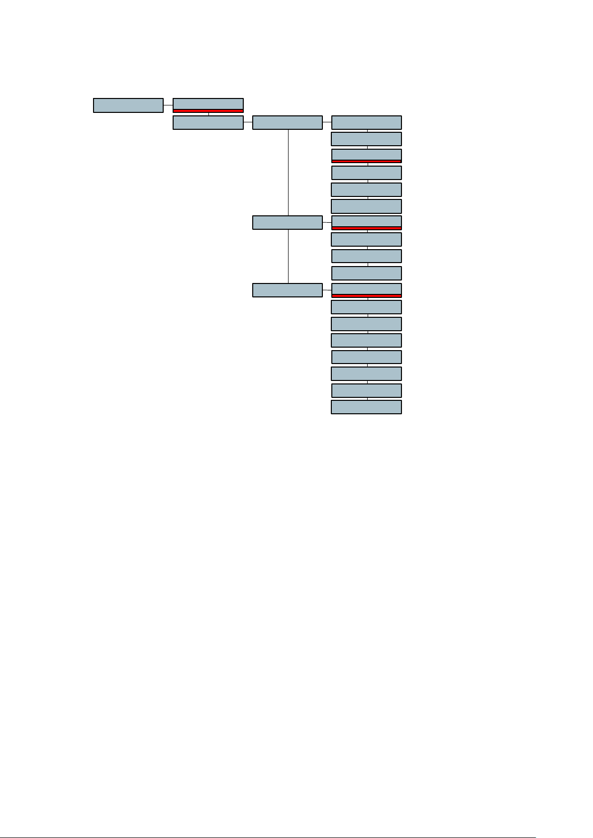
AUTO RECORD MENU
OFFAuto Rec.
ON -6 dB
Threshld
-12 dB
-18 dB
-24 dB
-30 dB
-36 dB
Trig. Dly 0.0 SEC
0.1 SEC
0.3 SEC
1.0 SEC
Stop Dly
NONSTOP
5 SEC
15 SEC
30 SEC
1 MIN
2 MIN
5 MIN
15 MIN
The Auto Rec. menu permits to turn on or off the auto record mode. This mode of recording
permits to start automatically a recording depending on the settings of the different
parameters described below. Once the parameters set, put the machine in the record mode.
The recording will start once the requested level and length of any incoming sound is
obtained. This mode can also be combined with the pre-record buffer.
The Threshld sub-menu permits to adjust the level detection to start the recording and can
be set in steps of 6 dB from 6 dB to -36 dB.
The Trig. Dly (trigger delay) menu permits to adjust the continuous duration or length of the
sound level before the recording starts. It can be set from 0.0 seconds to 1 second. Example:
if you clap your hands a single time and the start delay is set to 0.1 second, the recording will
not start, as the handclap was shorter than 0.1 seconds.
The Stop Dly (stop delay) permits to adjust the duration of recording once the sound level
drops below the threshold level and can be set from 5 seconds up to 15 minutes or nonstop.
Chapter 2 33 March 2005
Page 50

DISK MENU
Disk FAT 32
Ext. DriveReformat
Twin Option
Int. Drive
FAT 16
FAT 32
FAT 16
The Reformat menu permits to format the recording media into a FAT 16 or Fat 32 mode.
Beware that recording media bigger than 2 GB must be formatted in Fat 32. FAT 16 allows
max. 2 GB.
REEL NB. MENU
ModeReel Nb. ON
OFF
Current Curr. XXX
Next Next XXX
The Reel Nb. Allows you to manage the first 3 digits of the file names in the folder. The
generic sound file name is rrrnnn.wav where rrr is the reel number and nnn is the index
number. The reel number is also used for the "TAPE" keyword in the metadata (see titling
menu). All files in a folder have the same reel number.
With the Mode set to ON this feature allows the auto numbering of the reel number so that
each folder has a different reel number automatically. When selecting a new or empty folder
as working folder the Nagra V uses the Next reel number.
The Next value is not immediately incremented by 1 to prevent holes in the numbering. It is
done when leaving the working folder either by selecting another folder or by powering off the
Nagra V. In this case and if the folder is not empty (it has at least 1 sound file), the reel
number is considered as used and the Next value is incremented.
The Next value can be modified to start the reel numbering from a specific value. When
modified, the next value is frozen, waiting to be assigned to an empty folder. The maximum
reel number value is 999.
With the Mode set to OFF, the Next value is not used and all new empty folders has a default
reel number of 000.
When selecting a non-empty folder as working folder, no reel number is assigned. The reel
number is extracted from the existing sound files name (the last index) in order to avoid mixed
reel numbers in the folder. This behaviour does not depend on Mode value.
The current reel number value of the working folder can be checked in the Current menu.
Changing the current reel number modifies all sound file names of the working folder in
accordance with the new value. The file metadata ("TAPE" keyword) is not modified.
Chapter 2 34 March 2005
Page 51

OTHER SETTINGS
TimeDate TimeOther T XX.XX.XX
XX.XX.20XXDate
Pow. Delay
PTT lev.
Software
RESET
The Other settings menu relates to various other selections within the machine that do not fall
easily into any of the other categories. There are several settings that are rarely accessed but
may be needed occasionally.
The Date Time menu is the internal clock of the machine and will be recorded in the directory
of the HDD. It is totally independent of the time code setting. It is set in the same way as a
time code, by moving to the desired digit using the arrow keys and changing its value with the
Up and Down keys.
The Pow.Delay is a very useful feature for the NAGRA V. Under normal circumstances the
machine will automatically switch Off when the main function selector is set to the STOP
position. When it is turned on again the user must wait about 20 seconds for the BOOT
process to finish. This menu allows the user to program the delay before the power is cut
totally, which should avoid inadvertently stopping the machine completely. It can be
programmed for 2 seconds or 5 seconds, or even manual. In the MANUAL position, the
machine will remain switched on permanently until there is no longer sufficient power fed to
the machine. The ONLY way to stop the machine in this case is to hold the SHIFT key while
turning the main function selector to the STOP position and then keeping the SHIFT key
pressed for an additional 2 seconds. Then the machine will power off completely.
MANUAL
2 SEC
5 SEC
4.4 VOLT
1.55 VOLT
V X.XX
DD-MM-YY
DV V X.XX TC V X.XX
The PTT lev. selection permits the selection of the output voltage on the banana connectors
on the right side of the machine, used when connecting to a telephone line.
The Software menu gives the user access to the different versions of software installed in the
NAGRA V. The first position shows the version V X.XX of the software in the lower half of the
machine. The DV X.XX indicates the deck version number, and the last position is the version
of the time code software.
The RESET position of the menus is used to reset the menus of the machine to the default
settings. This can be used if the user needs to be sure that no peculiar settings remain in the
memory, from previous users settings. However this will perform a POWER OFF of the
machine in order to reset everything. The reset function will only work if the machine is in the
STD.BY mode.
The RESET function does not erase the templates.
Chapter 2 35 March 2005
Page 52

CHAPTER 3
TIME CODE and SYNCHRONIZATION
GENERAL ..................................................................................................................................................... 2
THE TIME CODE FORMAT....................................................................................................................... 2
TIME CODE IN / OUT CONNECTION ...................................................................................................... 3
DISPLAYING A TIME CODE ..................................................................................................................... 3
TIME CODE SETTINGS............................................................................................................................ 3
SETTING OF THE INTERNAL GENERATOR ......................................................................................... 4
Time Code Format Selection ................................................................................................................. 4
Setting The Time .................................................................................................................................... 4
Setting The User Bits ............................................................................................................................. 4
SELECTING THE RECORDING SOURCE .............................................................................................. 4
JAM SYNC ................................................................................................................................................. 5
SELECTING THE OPERATING MODE OF THE USER BITS ................................................................. 5
TIME CODE ASSEMBLE MODE............................................................................................................... 5
SETTING TIME/USER DATA FROM EXTERNAL.................................................................................... 5
TIME CODE SYNCHRONIZATION........................................................................................................... 6
OffSet...................................................................................................................................................... 6
Chase Reference ................................................................................................................................... 6
Sync Mode.............................................................................................................................................. 6
OPERATIONAL THEORY IN TIME CODE ............................................................................................... 7
CONVERTING 24 FPS TO 30 FPS............................................................................................................ 7
THE 3:2 PULL DOWN ............................................................................................................................... 7
HD AND 23.976 FPS ................................................................................................................................. 7
WHAT ALL THIS MEANS .......................................................................................................................... 8
WHAT SHOULD MY NAGRA V BE SET TO?............................................................................................. 8
Chapter 3 1 Jan 2002
Page 53

(The NV-TC option must be installed for the time code system to operate)
GENERAL
Up until now the audio / video domain has always related the word SYNCHRONISATION with the speed
and direction of a tape transport, as is the case with an analogue machine using centre track time code.
That is to say that the speed of the transport is directly controlled with respect to an incoming time code
signal, and if this time code were to be reversed then the machine itself will reverse. In modern digital
recorders, especially computer based formats the notion of time code as a whole is different. In the
case of the NAGRA V the term synchronisation possibilities, covers aspects of time code, external
references, and the effects upon the outputs, clocks etc. In addition, features such as the pre-recording
buffer, and different sampling rates all have their own effect on the time code system and its operation.
THE TIME CODE FORMAT
Unlike previous time code NAGRA recorders, the NAGRA V does not record a continuous time code
signal, as is the case with traditional longitudinal formats. The NAGRA V simply records a time stamp
at the start of each recording and according to the selected frame rate and sampling frequency, the
time code value at any given point after that stamp is simply calculated by counting the number of
samples of digital audio.
This time stamp is recorded in the header of the .WAV file, which is in fact the BWF or broadcast wave
file format. This time code information is then readable by any computer device capable of reading a
Broadcast wave file format.
The time code system of the NAGRA V can be set to record all the currently accepted standard time
code frame rates which are as follows:
24 FPS -Film applications
25 FPS -PAL/SECAM Video and film to video applications
29.97 FPS -NTSC black and white television
29.97 DF -NTSC colour television
30 FPS -Film applications (NTSC)
30 DF -Film to video (NTSC)
In addition the NAGRA V can record any of the above frame rates either accelerated or retarded by
0.1% in order to deal with all the possible anomalies of the NTSC Pull up / down which means:
Frame rate 0.1% Actual frame rate Frame rate + 0.1%
23.976 24 24.024
24.975 25 25.025
29.940 29.97 30
29.97 30 30.03
These different frequencies are recorded when the selection is made in the Ref. Freq menu.
IMPORTANT: When the reference frequency menu is set to master +0.1% (or 0.1%) the entire
machine will speed up (or slow down). That is to say the time code AND the sampling
frequency of the audio. For example, setting the machine to 29.97 at 48 kHz sampling
frequency, and then selecting MASTER + 0.1% in the reference frequency menu
means that the machine will actually accelerate by 0.1% and the result would be 30
frame time code at a sampling frequency of 48.048 kHz. The ± 0.1% will be stored in
the memory of the machine when the power is turned off and will remain accurate for
one week.
Chapter 3 2 Jan 2002
Page 54

The time code system of the NAGRA V will also accommodate the traditional USER BITS modes of
DATE and FREE according to needs. All the settings and different selections concerning the internal
time code system of the NAGRA V are made using the MENU system. (See TIME CODE MENU). Each
of the time code operations is explained in detail below.
TIME CODE IN / OUT CONNECTION
The time code input and output is located on a 5 pole LEMO connector on the right side of the machine.
The pin connections correspond to that of the IV-STC, T-Audio-TC, NAGRA-D.
Pin # Connection
1 Ground
2 Time code input
5 Time code output
DISPLAYING A TIME CODE
The display on the front panel of the NAGRA V is used to display time code. Various different time code
indications can be displayed according to the selection made in the display menu. The chosen time
code (Internal Generator or External time code) can be displayed in either TIME or USER format.
DELTA TC, which is the changing difference between the external reference and the time code on the
index during the synchronising process, can also be displayed.
TIME CODE SETTINGS
If the modulometer illumination switch is moved briefly to the BAT position twice in quick succession the
display will scroll through the presently selected time code generator and synchroniser settings, the
default values are as follows:
25 fps (Generator format)
INT. GEN. (Record source)
TC EXT (Chase reference)
FIX. CLK. (Sync mode)
Chapter 3 3 Oct 2002
Page 55

SETTING OF THE INTERNAL GENERATOR
Time Code Format Selection
Go to the Time Code menu (see menus) and move to the right using the arrow keys to the Format
menu which will indicate the currently selected frame rate. Pressing the vertical arrow keys will scroll
through the different formats. Once the desired format is shown on the display press the EXE key and
the new selection will be made. A single beep will be heard to indicate that the command has been
accepted and the display will return to previously displayed option (Take, Remain etc.)
The accepted time code formats of the internal generator are as follows:
24fps
25fps
29.97fps
29.97df
30fps
30df
The internal generator will count across midnight at all frame rates and keep perfect time. However the
date will not change in the USER bits on the stroke of midnight when the generator is set to 29.97FPS
or at 30df as neither of these two frame rates are coherent with real time. At these two frame rates the
memory will continue counting for a week accurately. After that time a re-jam of the internal generator
should be performed.
Setting The Time
The internal generator of the NAGRA V can be set either using the arrow keys on the front panel, or
from an external time code source. Once the internal generator has been set from the EXT source the
counting is continued by means of the internal generator, hence there is no need to have a cable link
permanently. Jam sync is also possible and will be discussed later.
Move to the Time Code menu and press the right arrow to move the display to Gen display, allowing
access to all the settings of the internal generator. Move to the right to Format and then scroll through
the possible choices until Set Gen. is displayed. Move to the right and then scroll through the options to
the Set Time position. Moving right from here will display the time code digits, which can be modified
using the arrow keys. When the desired time is set press the EXE key.
Simply pressing the EXE key when FROM EXT is displayed in the Gen. menu sets the time code from
an external reference.
Setting The User Bits
The user bits are set in exactly the same manner as the TIME portion of the time code via the Set User
menu. Each digit is then set using the arrow keys. The user bits can be set to any value from 0 to F
(Hex) if they are in Free User mode. Alternatively they must correspond to the DD.MM.YY.xx format if in
the DATE mode.
SELECTING THE RECORDING SOURCE
From the format display, press the down arrow and the display will indicate Rec. Src. allowing the
selection of the time code source to be recorded. The options are, INTERNAL, JAM SYNC, EXTERNAL
or ASSEMBLE. Simply press EXE to select the desired source when displayed. When the ASSEMBLE
is selected and the machine is set to record, a seamless time code assemble will be performed each
time a new take is started.
Chapter 3 4 Oct 2002
Page 56

JAM SYNC
In the JAM sync position, the internal time code generator of the NAGRA V will automatically be set as
soon as a VALID time code is connected to the time code input connector. If the cable providing the
external time code signal is left connected to the machine, a new JAM SYNC will be performed
automatically as soon as the machine detects a difference between the internal time code generator
and the external signal of more than 2 mS. An automatic JAM SYNC will also occur if a difference in the
USER information is detected between the incoming signal and the information in the internal generator
of the machine. For the JAM sync function to operate when the cable is connected, certain conditions
are verified before the set is made and these are: The incoming TC must be VALID and at the correct
speed (± 1%) for 10 consecutive frames. Frozen or Reverse time code will not provoke a JAM to occur.
This means that connecting the external signal to the machine for one second is largely long enough
for the machine to check all the parameters and set the generator.
SELECTING THE OPERATING MODE OF THE USER BITS
From the FORMAT position press the down arrow twice and the display will show USER MODE. When
pressing the right arrow now, the operator can select the operating mode of the internal generator for
the user portion of the time code signal. There are four different modes that can be selected. The most
important selection here is between the DATE or FREE positions. The user bits must be in the same
format as the external source if setting is to be made in either direction. The other two possibilities for
the user bits are FREE INC or DATE INC. These two are essentially the same as the normal date and
free modes except the right-most two digits are automatically incremented by one, from 00 to 99, each
time the machine is put into the record mode.
TIME CODE ASSEMBLE MODE
Each time the machine is put into REC mode a full time code assemble will be performed. This is done
by calculating the time code value of the last frame of the previous take (taking into account the
sampling frequency) and using the next consecutive frame number as the time stamp for the beginning
of the next index. The index number will also be incremented at the same time. Pressing the STOP key
to create a new index during recording will also perform a time code assemble irrespective of the time
code setting.
SETTING TIME/USER DATA FROM EXTERNAL
From the FORMAT position scroll through the menu to the Set Gen. position and then move to the right
and select FROM EXT. This will immediately take the next correct, valid moving time code which arrives
on the LEMO connector and will set the internal generator. The internal generator will then continue to
count from this value irrespective of the external time code arriving.
Chapter 3 5 Oct 2002
Page 57

TIME CODE SYNCHRONIZATION
The time code system of the NAGRA V is fitted with an internal time code chase synchroniser. The
synchroniser performs in much the same way as the internal synchroniser of the NAGRA T-AUDIO TC.
It has the possibility to synchronise the machine either to an external time code that is fed to the LEMO
connector on the side of the machine, or to lock it to a video sync reference fed to the BNC connector.
Chase synchronisers in the digital domain are different from those used in analogue machines. If, for
example, the machine is synchronised to a reference that is not at the correct speed, then the entire
machine will change speed accordingly and digital output of the machine will not be at the correct
sampling frequency which will cause problems during digital transfers.
The internal synchroniser of the NAGRA V is activated, by pressing SHIFT while selecting the PLAY
position of the main function switch. While the machine is in the sync mode, if the STOP key is pressed
then the machine will pause and upon the next press of the STOP key the synchronisation process will
be resumed. The internal synchroniser of the NAGRA V has various different parameters and operating
modes. The four principal sections are OFFSET, CHASE REFERENCE, SYNC MODE and REACTION
TIME, each of which is described below:
OffSet
The offset is the programmable difference between the time code reference and the time code coming
from the recorder. This can be set in the same manner as the time code values, by using the arrow
keys to set the value followed by the EXE key. An offset can be reset to zero at any time by executing
the RESET function in the menu.
Chase Reference
The chase reference menu has three choices, TC EXT, TC INC and VIDEO. In the TC EXT position the
internal synchroniser will lock to the incoming time code exactly. In the TC INC position, as soon as the
SYNC function is activated, the synchroniser will read the external time code reference value and the
value of the time code on the take to be synchronised and will immediately calculate the difference
between them. This difference is then stored in the OFFSET register and remains a fixed offset until the
next time the SYNC operation is activated.
In the VIDEO position the time code will be locked to the incoming video signal connected to the BNC
connector on the side of the machine. The synchroniser will lock the 0 frame of the time code to the
rising edge of the sync pulse in the video signal.
Sync Mode
There are two different modes in which the internal synchroniser can operate. One is called the VAR
CLK (variable clock) mode and the other is the FIX CLK (fixed clock).
Fix Clk
In the FIX CLK mode the machine will always follow the external reference.
Once the machine is in the LOCKED state the internal synchroniser will no
longer influence the transport and the playback speed is controlled entirely
by the reference frequency (REF FREQ menu). If however the
synchroniser of the NAGRA V sees an error of more than 1 frame, it will reengage itself to correct the synchronisation error. This is the recommended
operating mode. In this mode the maximum variation accepted is 100ppm.
Var Clk
This mode is designed to allow the machine to follow an external reference
that is not the same as the REF FREQ using the internal synchroniser. This
setting allows the internal synchroniser to modify the internal clocks in such
a way as to follow this REF FREQ (for example NTSC / NTSC 60). In this
mode, the digital output is not available and the quality of the analogue
outputs may be slightly degraded. In this mode variations of up to ± 4% in
the reference signal will be tolerated.
Chapter 3 6 Jan 2002
Page 58

OPERATIONAL THEORY IN TIME CODE
CONVERTING 24 FPS to 30 FPS
30 fps Time Code is used when transferring film to 29.97 fps video for video/workstation editing or when
transferring to magnetic (Sprocket) film. The following chart shows the frames that are coincident
between 30 fps and 24 fps.
24fps 30fps Real Time
Frame # 0 0 Start of the Second
Frame # 4 5 166.6667 mS
Frame # 8 10 333.3333 mS
Frame # 12 15 500 ms (Half a Second)
Frame # 16 20 666.6667 mS
Frame # 20 25 833.3333 mS
As shown in the chart above, every fourth frame at 24 fps matches every fifth frame at 30 fps. The film
transfers at a rate of 23.976 fps when converted to video at 29.97 fps during the 3-2 pull down. At the
same time the audio is also slowed down from 30 fps to 29.97 fps. This results in an exact match in the
video transfer. Recording 30 fps time code at 48 kHz means that the transfer house has to sample your
tape at 47.952 kHz (using special decks) to achieve the 0.1% pull down if the audio signal is to remain
in the digital domain. If the audio recorder supports the 48.048 kHz sampling rate then the tape can be
played back at 48KHz, which produces the same 0.1% pull down using the standard available decks
while keeping the audio in the digital domain.
THE 3:2 PULL DOWN
NTSC video frames are composed of two interlaced fields, each containing half the picture information.
One field contains all the odd scan lines, the other all the even scan lines. When 24 frame film is
transferred to NTSC, the first film image is placed in three successive video fields and the second frame
image is placed in the next two successive video fields. This process is repeated until the end of the
film. Artefacts of this process can be seen if you play the videotape in very slow motion. This process is
needed in order to transform the 24 frames of film into 30 complete video images. In order to make this
compatible with the NTSC video format the 24 frames of film are slowed down by the Telecine by 0.1%
(to 23.976 fps) and the resulting video signal is no longer 30 fps but 29.97fps.
HD AND 23.976 FPS
High Definition Cameras are capable of running 24 fps progressive scan (24P). This is different to
NTSC, which is 29.970 interlaced. If you use 24P, it must be converted to 29.97 fps NTSC for video
assist or editing on an Avid. When running 24P HD video, the audio TC must run at 30 fps. Currently the
down conversion from 24P is not practical. A solution is to run the HD camera at 23.976. The High
Definition conversion to NTSC video can then use the available standards converters. The following
chart shows the frames that are coincident between 23.976 and 29.97 NTSC.
23.976fps 29.97fps Real Time
Frame # 0 0 Start of the Second
Frame # 4 5 166.8333 mS
Frame # 8 10 333.6667 mS
Frame # 12 15 500.5 ms (Half a Second)
Frame # 16 20 667.3333 mS
Frame # 20 25 834.1667 mS
Again, every fourth frame at 23.976 fps matches every fifth frame at 29.970 fps. What does this mean
to the audio Time Code? Just run it at 29.97 fps! The same sync relation from the 3-2 pull down chart
holds true. The difference being that there is no speed change on the audio or video and the sampling
rate can stay at 48KHz.
Chapter 3 7 Jan 2002
Page 59

WHAT ALL THIS MEANS
Understanding the 3-2 pull down and how 24 fps and 30 fps relate it is easy to see how 23.976 fps and
29.970 fps relate as well. Don't be confused by these "new" numbers. 23.976 fps is used so that down
conversion for contemporary video assist is a simple real time matter. The good news is that there really
is nothing new.
WHAT SHOULD MY NAGRA V BE SET TO?
As a rule one should always check with the post production facility first to see how the next stage in the
production is going to be handled. Below is a table for your guidance.
APPLICATION TC Frame
Rate (fps)
Shooting Video in PAL / SECAM countries 25 44.1 / 48 Master
Shooting Film in PAL / SECAM countries 25 44.1 / 48 Master
Shooting Film in NTSC countries 29.97 44.1 / 48 Master
Shooting Video in NTSC countries 29.97df 44.1 / 48 Master
Shooting 24P HD video 29.97 44.1 / 48 Master
(To be continued)
Sampling
Frequency
(kHz)
Reference
Frequency
+0.1%
Chapter 3 8 Jan 2002
Page 60

CHAPTER 4
OPERATING THE NAGRA V
PREPARATION OF THE MACHINE...................................................................................... 2
FORMAT OF A HDD.......................................................................................................... 2
SETTING THE INTERNAL CLOCK.................................................................................... 2
TIME AND DATE............................................................................................................... 2
POWERING OF THE MACHINE ........................................................................................... 3
GENERAL ......................................................................................................................... 3
NV-LIB (Lithium Ion battery box/charger)............................................................................ 3
DRY CELLS.......................................................................................................................4
NA-DC2(NiCd or NiMH battery box / charger) .................................................................... 4
EXTERNAL POWER ......................................................................................................... 4
INDICATIONS....................................................................................................................... 5
BATTERY MENU............................................................................................................... 5
MODULOMETER .............................................................................................................. 5
BEEP WARNING...............................................................................................................5
THE POWER DELAY MODE................................................................................................. 5
USING THE NAGRA V.......................................................................................................... 6
INSTALLING THE HDD DRAWER..................................................................................... 6
Removing the HDD drawer............................................................................................. 6
RECORDING ........................................................................................................................7
SETTINGS PRIOR TO RECORDING.................................................................................7
TIME CODE.......................................................................................................................7
SAMPLING FREQUENCY / REFERENCE FREQUENCY .................................................. 7
RECORDING FORMAT ..................................................................................................... 7
INPUT SETTINGS............................................................................................................. 7
PRE-RECORDING MEMORY............................................................................................ 8
MICROPHONE SELECTION ............................................................................................. 8
MAKING THE RECORDING .............................................................................................. 8
RECORDING AN ANALOGUE LINE INPUT SIGNAL......................................................... 9
RECORDING A DIGITAL INPUT SIGNAL..........................................................................9
MONITORING THE AUDIO SIGNALS................................................................................... 9
AUDIO MONITORING ON HEADPHONES........................................................................ 9
AUDIO MONITORING ON THE INTERNAL SPEAKER......................................................9
VISUAL MONITORING ON THE MODULOMETER............................................................9
CAMERA RETURN MONITOR FEATURE....................................................................... 10
REPLAYING RECORDINGS............................................................................................... 10
ERASING RECORDINGS ................................................................................................... 11
RENUMBERING TAKES..................................................................................................... 11
Chapter 4 1 May 2003
Page 61

PREPARATION OF THE MACHINE
FORMAT OF A HDD
The HDD is already formatted when purchased. The format is actually FAT 32 and is
compatible with all PCs. HDD's should generally be formatted FAT 32 as formatting to FAT
16 will limit their size to 2GB of usable space.
Once used on a Nagra-V, a NAGRAV folder will be automatically created.
The other information in the root are not necessarily needed but will not affect the Nagra-V.
Inside the NAGRAV folder, the following information is stored:
Each file is recorded as a nnnxxx.wav Broadcast Wave Format file. nnn stands for the or
HDD number, xxx stands for the index number. All information such as record date and
time, Time Code stamp, 24 or 16 bit, sampling rate etc. are stored in the chunk of the file.
SETTING THE INTERNAL CLOCK
When the NAGRA V is first powered on, certain settings need to be made, namely those of
the date and time. This information will be used to stamp the files recorded to the HDD in the
same way a PC does for a diskette. These settings have no bearing on the internal time code
system (if fitted).
TIME AND DATE
The NAGRA V is equipped with a lithium battery (Type CR2032), which keeps the date and
time of the machine in memory. Naturally this needs to be changed if you change time zones.
It is also important to set this from time to time as such clocks tend to drift a bit. In order to set
the time and date, in the menu mode move to the Other settings menu and into the DateTime
menu. From here moving to the right makes it possible to set the Date and Time using the
arrow keys to select the correct values and Execute to store them.
Chapter 4 2 May 2003
Page 62

POWERING OF THE MACHINE
(-Ve is ground)
GENERAL
The NAGRA V is designed as a portable recorder for in the field On-Location sound
acquisition. Therefore it is designed to operate using autonomous battery powering. Today
there are many different types of batteries or accumulators available and the NAGRA V can
be powered in various different configurations.
Lithium Ion Pack (NV-LIB # 70 31110 000)
External power
Dry cells (NA-BB8B # 70 19111 000)
Other rechargeable cells
This section is designed to cover all aspects of the different powering possibilities, indications
and precautions that should be observed.
NV-LIB (Lithium Ion battery box/charger)
This accessory can only be used with a Nagra Lithium Ion pack (NV-LISET # 2098260000).
Which gives 65Wh of power. This powering solution is the lightest possible solution will give
an autonomy of approximately 7 hours. The NV-LIB is equipped with a charger circuit for the
NV-LISET cells and can be connected to an AC power supply (NV-PSU) via a standard DC
connector. The charge time is approximately 7 hours because Lithium Ion cells do not like to
be charged rapidly in the way Nickel Cadmium cells can. The charger can be connected while
the machine is being used which will prevent the power in the battery pack from being
consumed. It will power the machine AND charge the battery pack at the same time, but the
charging will be at a reduced rate.
Releasing the two plastic clamps towards the rear of the recorder allows the battery pack to
be changed very quickly. The memory of the internal time code generator will be kept for a
few minutes while the battery pack is being replaced. However the machine will need to be
Re-Booted once the new battery pack is installed.
NOTE: Only a NAGRA certified Lithium Ion pack should be used.
Chapter 4 3 Oct 2002
Page 63

DRY CELLS
The NAGRA V can also be operated using standard D cells which can be found all over the
world. However if D cells are to be used the machine needs to be equipped with the 8 cells
box (NA-BB8B # 70 19111 000). This option naturally adds quite a lot of weight to the
machine. In this event the user should select DRY CELLS in the battery menu.
To install the batteries remove the battery box on the rear of the machine by lifting the plastic
battery box clamps on each side of the rear of the machine and remove the battery box. Open
the upper lid of the battery box by squeezing the closing mechanism. When installing
batteries into the battery case, be sure that they are installed with the correct polarity
according to the sticker inside the battery case (+ve terminals towards the right-hand side of
the machine).
NA-DC2(NiCd or NiMH battery box / charger)
This accessory can be used with either 8 individual "D" size NiCd / NiMH cells or alternatively
the NA-ACC (#98253) accumulator sticks. If the NA-DC2 is connected to the external
transformer, but the NAGRA-V is either OFF or totally disconnected then the cells inside the
NA-DC2 will be recharged if the voltage is below minimum or if the white button is pressed.
The charging time for eight cells (or 2 sticks) is approximately 6 Hours (Charge current 0.8A).
Charging is automatically stopped when the internal temperature of the cells increases by 6C
with respect to the ambient temperature.
If the NAGRA-V is switched on while the batteries are connected to the external supply, then
the power will be supplied by the cells and not by the external supply. When the cells become
flat the charger will switch on but in this case will only charge the cells slowly as most of the
power being supplied to them will be used by the machine. If the machine is then turned OFF,
normal charging will resume.
The green LED on the end of the case indicates that the external DC supply is present. When
both the green led and the red led are alight the internal cells are being recharged.
EXTERNAL POWER
The NAGRA V is equipped with a 4 pole male XLR connector, which can be accessed by
removing the battery box. The pinning of this connector is between pins 1 (-ve) and 4 (+ve)
corresponding to the standard XLR powering configuration. This input will accept from 9 to
14.8 volts. The NV-PSU power supply will power the NAGRA V but an adapter needs to be
used.
Standard Camera battery belts can be connected directly to this point assuming their
voltage is within the accepted range.
Chapter 4 4 Jan 2002
Page 64

INDICATIONS
BATTERY MENU
In the menu mode of the machine there is a menu called BAT. This indication is purely a
counter, which counts in Hours and minutes since the last time it was reset. It will only count
while the machine is powered. It is designed to give the user a method of monitoring how long
the current battery pack has been used. The user can reset this each time the external battery
pack is replaced. It will also be reset whenever the selection of the type of battery is changed.
MODULOMETER
Indication of the state of the batteries / cells installed in the removable battery compartment
can be seen at any time by selecting BATT on the meter on the front panel of the machine. It
is important to select the correct battery type in the Battery menu so that the modulometer
indication and the low battery warnings are correctly adapted to the type of batteries installed.
The Green portion of the modulometer scale
indicates a fuel gauge and will approximately
indicate the current state of the supply. When
the supply becomes exhausted, a LOW BAT
indication will appear on the display and a beep
will be heard on the headphones.
This will be repeated every minute until the
machine cuts off. The cut off point varies
depending on the type of batteries selected in
the Battery menu.
BEEP WARNING
When the batteries of the NAGRA V get flat, a double beep will be heard in the headphones
(or on speaker if selected) once per minute. This will start when the supply voltage drops to
the lower limit according to the battery type selected. The beep warning is also accompanied
by a Low Bat indication on the LCD display on the front panel of the machine as well as the
POWER flag on the top of the display.
NOTE: Before power is cut off completely the machine will stop the current recording and
close the file correctly before switching off.
THE POWER DELAY MODE
Because the NAGRA V has a PC aboard, it needs to boot each time the power is turned on.
This process takes a little less than 30 seconds and can be a nuisance if the machine is
accidentally switched to the STOP position. To avoid this potential inconvenience, the
POWER DELAY menu in the OTHER settings menu allows the user to pre-programme how
long the machine will remain in the stop position before a complete power down is performed.
If the MANUAL position is selected then the machine will remain powered up indefinitely until
there is insufficient power supplied to the unit. In this position the only way to manually stop
the machine is to press the SHIFT key while moving the main function selector to the STOP
position and then keeping the SHIFT key pressed for an additional 2 seconds. The machine
will then shut down completely.
Chapter 4 5 Oct 2002
Page 65
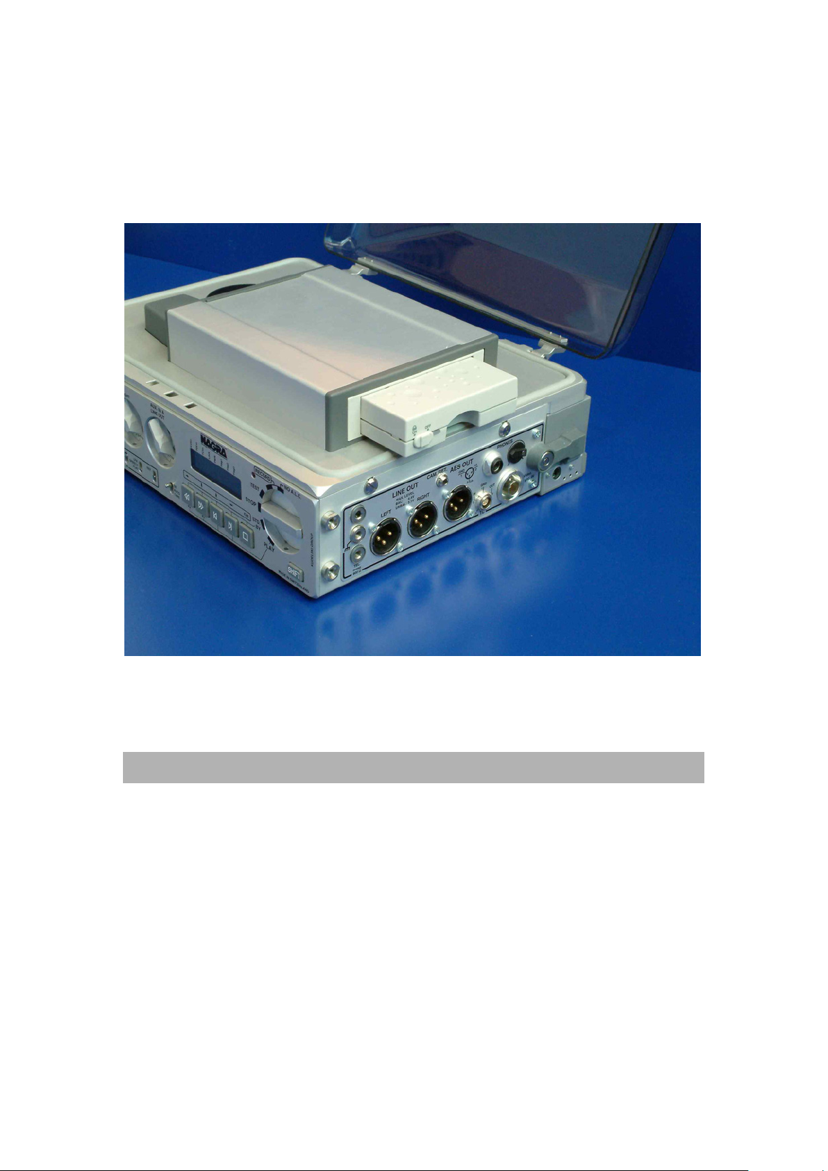
USING THE NAGRA V
New HDDs need to be formatted before use. Hard disks supplied from the factory are already
formatted FAT 32.
INSTALLING THE HDD DRAWER
Keep the machine switched off and insert the drawer into the machine as shown in the
photograph above. Before inserting completely, verify that the little switch on the drawer is in
the off position, insert fully and put the little switch to on. The switch also mechannically locks
the drawer in the bay.
ATTENTION: NEVER REMOVE A HDD WHEN THE MACHINE IS SWITCHED ON. HOT
SWAP IS NOT POSSIBLE.
Removing the HDD drawer
Always turn off the machine before removing the drawer. Put the little switch on the drawer to
the off position and remove the drawer.
Chapter 4 6 May 2003
Page 66

RECORDING
SETTINGS PRIOR TO RECORDING
Various settings of the machine should be made before the recording starts. Naturally these
settings are stored in memory but they may need to be checked before a recording is started.
The most important settings to be made are:
Time code
Sampling Frequency
Reference Frequency
Recording Format
Input selection
Pre-recording time
All of the above settings are made in the MENU mode of the machine.
TIME CODE
The time code should be set according to the required frame rate, recording source and user
bits mode. See Time Code chapter for full explanations of all these different settings.
SAMPLING FREQUENCY / REFERENCE FREQUENCY
Sampling frequency NV-96K can be set to either 44.1kHz or 48kHz (or 88.2kHz or 96kHz if
the High Sampling option is installed). The sampling frequency can be increased/decreased
by 0.1% (e.g. to record 48.048 kHz) by setting the reference frequency to the MASTER +0.1%
position. Otherwise, during the recording process the reference frequency must be set to the
MASTER position. (The reference frequency selections are only available for machines fitted
with the time code option NV-TC).
RECORDING FORMAT
The NAGRA V normally records a 24 bit digital word length. However in certain
circumstances, it may be necessary to record only 16 bits so as to remain compatible with
digital post production equipment which cannot handle the full 24 bit signal. In this case, the
signal on the HDD will be a true 16 bit signal. (It is also possible to re-dither a 24 bit signal
during playback to transform it to 16 bits see Output menu). Recording at 16 bits will
increase the recording time respectively.
INPUT SETTINGS
Before making a recording it may be necessary to select the audio input menu to change the
desired configuration. The most important selection here is the choice between ANALOGUE
or DIGITAL. If the input is a digital input then the special cable NV-CDI # 7031140000 must
be used.
In the analogue mode, there are 4 possible signal inputs. The first two are the standard
microphone inputs and there are two auxiliary inputs located on the 15 pole miniature D
connector. In the input menu it is also possible to select to which channel of the HDD each of
these four inputs is directed. Each can be set to Left, Right or Both channels as required.
Also the optional limiters can be disabled or enabled via the menus. The ganging of the two
limiters is only possible by setting the switch S3 to the corresponding position.
Chapter 4 7 May 2003
Page 67

The switches S1 and S2 must stay in the ON position. Only in this way can they be disabled
or enabled via the menus. If both switches are in the OFF position, the limiters will not be
enabled, even if in the menus, they were selected ON.
PRE-RECORDING MEMORY
The pre-recording memory can be set to record into RAM memory a pre-set length of time
while the machine is in the TEST position. This means that when the machine is put into
RECORD the previous X seconds prior to the recording function being operated, will
automatically be recorded to the HDD, with the corresponding time code. This eliminates the
need to worry about pre-rolls as they will be recorded automatically. This time can be set to 1,
3, 5, 10, 15 or 20 seconds.
MICROPHONE SELECTION
The NAGRA V allows Dynamic, Phantom +48V or T power microphones to be selected by
means of the toggle switch above each input connector. The sensitivity of the microphone can
also be selected using the two sensitivity switches located on the front panel of the machine.
The level is then adjusted for each microphone independently with the potentiometers on the
front of the machine.
MAKING THE RECORDING
The procedure described below covers the important steps necessary in order to record using
the NAGRA V. It does not give indications as to the type of microphones or their placement
but purely the steps that should be followed.
Initially ensure that the machine is either connected to an external power source or that the
battery box is fitted. Verify that the HDD drawer is inserted and turned on.
Select the desired powering using the selectors above the connectors according to the
microphones being used. Connect the microphone(s) to the input connectors on the left-hand
side of the machine. Once this is done set the microphone sensitivity selectors, located under
the microphone potentiometers on the front panel according to the type of microphone being
used. The sensitivity selections for a specific microphone are indicated in the documentation
of the microphone. (0.2V for dynamic and 1 and 4mV for condenser microphones).
At this point the selection of one of the three filters can be selected if required. The three
filters are LFA (Low Frequency Attenuation), SPEECH and FLAT, the curves for these are all
indicated in chapter I of this manual.
Verify the settings listed above concerning the sampling frequency, time code etc.
Verify also if there is a need to use the limiters (optional).
Set the EE / AUTO / TAPE selector to the AUTO position to allow monitoring of the audio on
the headphones.
Set the main function selector of the NAGRA V to the TEST position. The RED led will flash to
indicate that the machine is in the record mode (Pre-record) assuming this has been
programmed. If the pre-record is not programmed then the led will remain off.
Adjust the microphone input potentiometer (Left and / or Right) on the front panel until an
indication is shown on the modulometer. If no indication is shown when speaking into the
microphone refer to chapter V "Problem Solving" of this manual. Check that the AUX. IN /
LINE OUT potentiometer is not in the fully counter clockwise position or in the OFF mode
(menus). Adjust the headphone level using the headphone output level potentiometer located
to the right of the headphone connector.
Once audio is heard in the headphones and is correctly indicated on the modulometer simply
move the main function selector to the RECORD position. The contents of the pre-record
memory will then immediately be recorded to the HDD along with the corresponding time
code according to the selected time code settings.
Pressing the STOP "" key at any time during the recording will cause a new INDEX to be
created on the HDD, although there will be no audible break in the audio signal. This is very
useful for locating special events after the recording has taken place. When the recording is
completed return the main function selector to the TEST or STOP position.
Chapter 4 8 May 2003
Page 68

RECORDING AN ANALOGUE LINE INPUT SIGNAL
Recording a line input signal is performed in exactly the same manner, except the signal is
fed to the miniature 15-pole D connector and the level is adjusted using the AUX pot on the
front of the machine. A NAGRA made line input cable is available with either female or male
XLR connectors.
RECORDING A DIGITAL INPUT SIGNAL
Set the input menu to the AES position. Connect the special digital input cable to the 15 pole
miniature D connector. Set the reference frequency menu according to the digital input
supplied. If this is not set then the internal clocks will not be synchronised to the incoming
AES signal and there will be clicks in the audio due to missed samples. (The Red LED will
flash as a warning if this is the case).
MONITORING THE AUDIO SIGNALS
AUDIO MONITORING ON HEADPHONES
Headphones having an impedance from 4Ω to 100Ω are ideal for operation with the NAGRA
V. They should be connected to the headphone socket on the right side of the machine and
the audio level is adjusted using the potentiometer next to the connector.
NOTE: The line input potentiometer on the front of the machine is electronically in series with
the headphone level pot. Therefore if it is set to the ZERO position then there will be
no signal on the headphone output.
During recording the headphones will monitor the incoming audio signal on the selected
inputs.
Pressing the BAT switch at any time will feed the audio signals to the headphones in the
mono mode while the switch is activated as long as the monitoring menu is set to the
STEREO position. If the monitor menu is set to the TOGGLE position then the headphone
monitoring will switch from MONO to STEREO each time the switch is pressed. In the MONO
position then the monitoring will be in MONO all the time. When in STEREO position, the
inputs can also be monitored as SOLO. Pushing the switch L max. R to L or to R will
reproduce on the headphones only the left channel or the right channel in mono. This is only
possible on machines equipped with a box motherboard 9131 300 000 B or higher. If needed,
the older board 91 31 300 000 A can be modified by your local agent.
AUDIO MONITORING ON THE INTERNAL SPEAKER
The NAGRA V is fitted with an internal speaker that enables the user to listen to the
recordings on the drive. The internal speaker can be turned ON or OFF in the Monitor menu
as required. It is also possible to select the AUTO position. In this mode the speaker will be in
the ON position during playback and will be muted in the TEST and RECORD positions.
A shortcut has been implemented to allow the user to rapidly change the speaker operation
mode. Pressing the SHIFT key and simultaneously pressing the BAT switch will toggle
between the three possible operating modes of the loudspeaker consecutively.
VISUAL MONITORING ON THE MODULOMETER
The modulometer of the NAGRA V has several different operating modes and can indicate
different readings. These are chosen partially in the menus of the machine and partially using
the selector switches next to the modulometer. Equally the modulometer is fitted with two
LEDS which also can be selected to have different operating modes.
Machines equipped with a box motherboard 9131 300 000 B have the possibility to set the
modulometer before or behind the line output potentiometer (electronically speaking).
Machines with the previous board 9131 300 000 A if needed can be modified by your local
agent. In the case that the modulometer is set before the line output potentiometer, the menu
selection LEV.IN & LEV.OUT no longer exist. The changing of the jumpers can only be made
Chapter 4 9 May 2003
Page 69

by your local agent as some hardware options need to be enabled or disabled, otherwise the
modulometer reading will be wrong.
First of all, in the menus, the source of the modulometer can be selected to indicate the Input
or output signal level. In the AUTO position it is set to show the input level during TEST and
RECORD and the output level during PLAYBACK.
The operating mode of the two leds can also be selected to either STEREO or TWO
CHANNEL operation. In the stereo mode the leds indicate which channel has the highest
signal level. In the two channel operation the leds indicate the actual level on the left and right
channel respectively allowing verification that the signal arrives on the respective input.
The three position switch L / MAX / R below the modulometer will force the pointer to
indicate the selected channel. In the MAX position it will always indicate the greatest signal
level of the two channels (which is identified by the corresponding led, when set to the stereo
mode.)
This is not anymore the case if you have purchased a NAGRA-V with double modulometer.
The same switch will only select the headphone outputs between Stereo, Solo left or Solo
right.
The pointer can also indicate the highest level achieved since the last reset by setting the
MEM / NORM / RESET switch to the MEM position. In the NORM position the modulometer
indicates as above and in the RESET position the highest level in memory will be reset to
zero.
CAMERA RETURN MONITOR FEATURE
When sound engineers are recording in video applications, the audio is frequently recorded
directly onto the audio tracks of the video camera. In this case the engineer has no feedback
from the camera to verify that the recording is being made correctly. The Camera return input
on the right side of the NAGRA V allows the headphone output (or line output) of the camera
to be connected back into the NAGRA V so that the sound engineer can verify the recording
quality on the video camera.
In this case the NAGRA V is being used principally in the role of a small mixer, but of course
can still record the audio in full 24 bits if required to the HDD.
If the camera return monitoring input is to be used, it must be selected in the MONITOR
menu, by executing the CAM RET position. Moving to the right gives the operator the
possibility to adjust the headphone level for this input by +6dB to -12dB.
The camera return signal will be fed to the headphones whenever the user selects the TAPE
position of the EE / AUTO / TAPE switch.
REPLAYING RECORDINGS
If the replay function is chosen immediately after a recording, then the machine will
immediately play back the last recorded take. If PLAY is selected once the data has been
read the machine will automatically start playing back the first take on the HDD which was
recorded in the same format as the machine is currently set.
That is to say if the machine is set to 24 bit 48kHz sampling, and the first track to be replayed
will be the first track on the HDD which was recorded at 24 / 48 kHz. If there are no takes
recorded at the same bit rate as the machine is currently set then the machine will just sit in
the same place.
When the main function selector is set to the play position, the fast forwards, fast rewind and
skip keys are all activated. (See full description of each function in chapter 1)
Chapter 4 10 May 2003
Page 70

ERASING RECORDINGS
It is possible to erase either individual takes, or from any point to the end of the HDD using
the directory menu.
In the directory menu, all the current recordings are displayed one after the other in a list, in
the same way as files are listed on the directory of a diskette. If the EXE key is pressed while
in this menu a sub-menu will appear and gives the user the possibility to delete the current
take, or to the end of the HDD. It also allows the takes to be renumbered if desired (See
Renumbering Takes). Pressing execute on any of these choices will prompt the SURE?
question to avoid accidents. Executing the ABORT position returns to the directory menu.
RENUMBERING TAKES
If takes have been erased from the HDD it may be useful to renumber the takes so that all
the numbers run consecutively. If necessary go to the directory menu and display the take
number from which the renumbering is to start. Press the EXECUTE key and then choose the
option RENUMBER to start renumbering from the current position to the end. The REN. ALL.
Function will automatically renumber all the recorded takes. Naturally this operation will have
no effect on the time code of the recordings.
Chapter 4 11 May 2003
Page 71

Chapter 5
POST-PRODUCTION
POST PRODUCTION............................................................................................................ 2
GENERAL ......................................................................................................................... 2
SYNCHRONISING WITH THE INTERNAL CHASE SYNCHRONISER............................... 2
ACTIVATING THE INTERNAL SYNCHRONISER .............................................................. 2
SYNCHRONISER MODES (CHASE REFERENCE)........................................................... 2
CLOCK REFERENCES.....................................................................................................3
POST PRODUCTION WITHOUT NAGRA V ...................................................................... 3
HDD IN POST PRODUCTION ........................................................................................... 3
Chapter 5 1 May 2003
Page 72

POST PRODUCTION
GENERAL
Being a computer based format, and a perfectly standard Broadcast wave FAT 16 or FAT 32
file format, post production, as we know it, will generally not be performed using the NAGRA
V in any way.
Naturally the concept of the format means that the HDD is removed from the NAGRA V and is
sent to post-production which is entirely performed using digital workstations etc. However,
there may be certain circumstances where the NAGRA V is needed for the transfer process.
This section explains how to use the NAGRA V in post-production, the necessary settings of
the NAGRA V during production so that the post-production becomes as simple as possible
and finally the principle post-production procedures concerning the NAGRA V audio material.
SYNCHRONISING WITH THE INTERNAL CHASE SYNCHRONISER
The NAGRA V is equipped with an internal time code chase synchroniser that allows the
machine to chase and follow any external time code reference.
The external time code reference must be connected to the 5-pin LEMO socket on the right
side of the machine.
ACTIVATING THE INTERNAL SYNCHRONISER
Pressing the SHIFT key while selecting the PLAY position of the main function selector
activates the chase synchroniser.
SYNCHRONISER MODES (CHASE REFERENCE)
The synchroniser can operate in various different modes, which are chosen in the
synchroniser part of the time code menu.
TC EXT In this mode the time code of the take on the HDD is locked perfectly
to bit accuracy with the external time code fed to the LEMO
connector. The machine will remain perfectly in sync and will copy
the speed of the external signal perfectly.
TC INC In this mode the time code fed to the machine and that of the file to
be synchronised are not the same. At the moment the synchroniser is
activated the exact difference between the two values is calculated
and stored in the offset register. This offset then remains constant
until the next synchronisation command.
VIDEO This is the position which should be selected if the machine is to be
locked to an external PAL or NTSC video signal. In this mode the 0
frame of the time code second is locked to the leading edge of the
video frame pulse signal fed to the BNC connector.
Chapter 5 2 May 2003
Page 73

CLOCK REFERENCES
Fix Clk In the FIX CLK mode the machine will always follow the external
reference. Once the machine is in the LOCKED state the internal
synchroniser will no longer influence the transport and the transport
speed is controlled entirely by the reference frequency (REF FREQ
menu). If however the synchroniser of the NAGRA V sees an error of
more than 1 frame, it will re-engage itself to correct the
synchronisation error. This is the recommended operating mode.
Var Clk This mode is designed to allow the machine to follow an external
reference that is not the same as the REF FREQ using the internal
synchroniser. This setting allows the internal synchroniser to modify
the internal clocks in such a way as to follow this REF FREQ (for
example NTSC / NTSC 60). In this mode, the digital output is not
available and the quality of the analogue outputs may be slightly
degraded. Such a situation arises when the take has 30FF time code
and the external reference is NTSC (59.94). The machine will slow
the audio down to 29.97fps.
POST PRODUCTION WITHOUT NAGRA V
Under normal circumstances the post production of the audio files recorded on the NAGRA V
will performed entirely in the post production facility. In this case it is important to know how
the post production is going to be done before starting the production, and thus the NAGRA V
can be set in the correct manner from the start.
Important points to verify are the Time Code frame rate being used and the digital audio
sampling frequency and word length that the post production facility is going to use.
If the frame rate is incorrectly set during the recording it may be impossible to sync up the
audio afterwards. If the incorrect sampling frequency is used the signal will either need to be
fed through a sample rate converter, or alternatively the audio will need to be taken out of the
digital domain via a D/A converter during transfer. In both cases there will be an unnecessary
lowering of the audio quality. Equally if the post production chain cannot deal with the full 24
bit word length, it may be advisable to make the initial recordings with the NAGRA V set to
16bit configuration. This avoids undesirable truncation during post production of the digital
signal, or alternatively standard conversion.
In the ideal situation the recordings will be made at 48 kHz 24 bits with time code according to
the standard frame rates. In this case the HDD is sent for post production and the user starts
afresh with a new one the following day.The machine my require a spare drive or two in order
to cycle the drives through Post.
HDD IN POST PRODUCTION
The post production house must be equipped with a HDD IDE adapter in order to be able to
replay the HDD coming from the field that were recorded on the NAGRA V.
The HDD adapters are available in the following formats.
IDE/USB2 adapter #2097 937 000
IDE/Fire Wire adapter #2097 939 000
IDE/PCMCIA adapter #2097 935 000
Each of the above is delivered with the necessary drivers on CD-ROM for the installation.
Once installed, the HDD drive appears as an additional drive to the editing system. The audio
can be downloaded directly from the master into the system. We have tested the HDD
adapters with various different operating systems (Mac, Windows 98SE, 2000, XP and NT4)
without any problems.
Chapter 5 3 May 2003
Page 74

Chapter 6
PROBLEM SOLVING
DISPLAY MESSAGES .......................................................................................................... 2
PROBLEM LOCATION.......................................................................................................... 3
ACCESSORIES AND CODE NUMBERS............................................................................... 4
Chapter 6 1 May 2003
Page 75

DISPLAY MESSAGES
Low Bat. Batterie voltage too low
Unlock No or wrong external sync available or clock failure
Cmd. Fail Error coming from the lower box, unable to execute a transport command
Deck err. Upper deck not responding (booting or frozen)
Disk err. Something went wrong with the HDD
Booting During startup of the machine
UpdateOk When the machine has finished to install a new software
Ver. Error When during an update 2 different none compatible version are present
No Disk If the HDD is not present or not switched on
Bad Disk Unknown format or unformatted HDD
Dir.Error Directory error. Cannot create the nagrav directory (file name conflict)
Reading The machine is reading the HDD directory (after booting)
DiskBusy The HDD is finnishing a job
DiskFull No more disk space
Disk Jam Electrical or mechanical HDD problem
Dir. Full The highest file number reached the index 999
DateLost Due too long storage or no battery, date and time is lost
WaitTrig. Before starting recording in the Auto Rec mode.
The machine is waiting for the trigger to start recording
Stopped Recording stopped by the remote connector input
(start/stop signal for record or play).
.
Chapter 6 2 May 2003
Page 76

PROBLEM LOCATION
PROBLEM REASON REMEDY
No signal on the modulometer in
Test /Record positions
There is something on this HDD but
my NAGRA V wont see it
No signal on the headphones
No signal on the internal speaker
Only hear the audio on one channel Channel matrix incorrectly set Verify the INPUT menu and check
Record LED Flashing during record
The REC led is flashing in the TEST
position.
Record led flashing while recording a
digital input
Unable to switch the machine OFF Power delay set to MANUAL Hold shift while selecting STOP and
Unable to switch the machine on
although power is connected to the
4 pin XLR connector
No disk displayed when HDD is
installed
No audio in playback Disk read error Probably due to shocks keep
Modulometer menu set to LEV. OUT Select either AUTO or LEV IN in
Inputs set to AES Set SOURCE in the input menu to
Inputs set to Analogue when trying
to record a digital input
Internal channel routing switches
incorrectly set
Matrix menu has all inputs set to the
OFF position
Wrong bit rate / sampling frequency
selected
Headphone potentiometer turned
fully counter clockwise
Line output pot turned fully counterclockwise.
Incorrect position of EE/AUTO/TAPE
switch
Line potentiometer turned fully
counter-clockwise
Speaker set to OFF Set the LOUD SPK. Menu to the
Headphone potentiometer turned
fully counter-clockwise
An external reference has been
selected but is not present on the
BNC connector. (Fast flash)
AES Inputs selected and no digital
signal present. (Double flash)
Recording is being made into
memory. (Slow flashing)
Clock problem (Fast flash) Verify external reference
This is normal if the PRE-RECORD
function has been set
Clocks not locked to incoming digital
signal
The power available is lower in
voltage than the current BAT setting
will allow (e.g. external 9V)
Disk has errors on it and cannot be
read correctly
HDD is not formatted FAT Reformat HDD or replace it
modulometer menu
ANALOGUE
Set SOURCE in the input menu to
AES
Verify the switch positions on the
main mother board
Select the desired inputs to Left,
Right or Both positions.
Verify the bit rate / sampling
frequency of the take in the
DIRECTORY menu and set the
machine accordingly
Increase the headphone level
potentiometer
Verify and adjust potentiometer
position.
Set switch to the AUTO position
Increase level of Line potentiometer
AUTO position.
Increase level of headphone
potentiometer
that the inputs are switched to the
correct channels
Connect correct reference to the
BNC connector or select MASTER in
the Reference Frequency menu
Apply digital signal to inputs or set
inputs to analogue
HDD may be faulty. Replace HDD.
Ignore it, or switch off the Pre-record
function in the menu mode
Check REF FREQ setting is set to
the same position as the incoming
signal. (e.g. 48 kHz)
keep shift pressed for 2 secs.
Press the BAT switch while turning
the main selector and then verify the
setting of the battery menu. If
necessary select the OTHER
position.
Replace with a new HDD.The machine will not accept a HDD.
Verify that the HDD switch is on
machine still.
Chapter 6 3 May 2003
Page 77

ACCESSORIES AND CODE NUMBERS
Description of the different accessories for the NAGRA V along with their code numbers
7031003000 NAGRA VH
7031004000 NAGRA VHT
7031120000 NV-TC Time code option for NAGRA V, delivered with:
7031130000 NV-LIM Internal audio limiter circuit
7031145000 NV-96K High Sampling frequency option for NAGRA V
7031162000 IHD Internal HDD option for NAGRA V (incl. 60 GB disk)
7031152000 HD-40G Removable drawer including miniature Hard Disk Drive 40 GB
7031153000 HD-60G Removable drawer including miniature Hard Disk Drive 60 GB
7010540000 ND-PCA
7031110000 NV-LIB Battery box with lithium Ion battery pack 65W, with charger circuit.
7019111000 NA-BB8B Battery Box for 8 "D" cells
7031100000 NV-COM PC Software for NAGRA V
2031150000 NV-PSU Mains power supply for NV-LIB
2031155000 NV-CH Metal Carrying handle for NAGRA-V / ARES-C
2097940000 NV-NTA Ambient external NP-1 battery pack adaptor
2098260000 NV-LISET Replacement set of Lithium Ion battery pack 65W for NV-LIB
2099185000 NV-SCC Soft carrying case for NAGRA V equipped with NV-LIB battery box
2097230000 NV-DRAW Removable drawer for miniature Hard Disk (Empty)
NAGRA V, 24 bit portable linear digital HDD recorder,
Equipped with SINGLE modulometer
(Without battery compartment or hard disk drawer) delivered with:
Carrying strap,
Instruction manual (English edition)
NAGRA V, 24 bit portable linear digital HDD recorder,
Equipped with DOUBLE modulometer
(Without battery compartment or hard disk drawer) delivered with:
Carrying strap,
Instruction manual (English edition)
INTERNAL OPTIONS
QCTCU Time code cable
EXTERNAL ACCESSORIES
Adaptor RS232 (PC) / RS422 (N-D) for serial PC connection
for the operation of the NADCOM softwares
CABLES
2097935000 HD-PCM PCMCIA / IDE adapter from HDD to PC
2097937000 HD-USB USB2 / IDE adapter from HDD to PC
2097939000 HD-FW FIREWIRE / IDE adapter from HDD to PC
2095970000 CXLR-FM 3-pin XLR Cable male-female 1.5 m (5 ft)
2095971000 CXLR-FF 3-pin XLR Cable female-female 1.5 m (5 ft)
2095972000 ECXLR-FM 3-pin XLR Cable male-female 10 m (33 ft)
7010901000 DCR Microphone input cable DIN 3F-XLR M 1.5 m (5 ft)
7016908000 QCTC Time code cable Lemo-Lemo
7031140000 NV-CDI Digital input cable 15-pin mini D XLR 3-pin female 1.5m (5 ft)
2095974000 C-LIN-FF Line input cable 15-pin mini D 2 XLR 3-pin female 1.5m (5 ft)
2095973000 C-LIN-MM Line input cable 15-pin mini D 2 XLR 3-pin male 1.5m (5 ft)
Chapter 6 4 July 2004
Page 78

CHAPTER 7
SPECIFICATIONS
TECHNICAL SPECIFICATIONS.......................................................................................................... 2
RECORDING...................................................................................................................................2
INPUTS ...........................................................................................................................................2
OUTPUTS .......................................................................................................................................2
GENERAL .......................................................................................................................................2
SAFETY/COMPLIANCE...................................................................................................................... 3
Chapter 7 1 Jan 2002
Page 79

TECHNICAL SPECIFICATIONS
RECORDING
Data Storage medium Removable HDD (removable hard disk)
Recording method Linear PCM
File Format Broadcast Wave File
A/D and D/A conversion 24 bit Sigma Delta (16 bit or 24 bit word length)
Sampling Frequencies 44.1 kHz, 48 kHz (88.2 kHz and 96 kHz with option)
Recording capacity 1hr of 24 bit 48 kHz per GB of disk space
Level meter Analogue modulometer(s)
INPUTS
Microphone inputs 2 x XLR (Dynamic, T Powering and +48 Phantom)
Microphone input sensitivity 0.2, 1 and 4 mV/hPa
Line inputs 15 pin miniature D connector
Line input sensitivity Uin min. for 0 dB = 1.55V
Uin max for 0 dB = 4.0V
Input filters Flat, LFA and SPEECH
AES input 15 pin miniature D connector using special cable
External reference 15 pin miniature D connector or BNC.
OUTPUTS
Analogue line output 2 x XLR (0.775V for 0 dB)
U
max balanced = 4.4V
out
U
max Unbalanced = 3.2V
out
THD at 1 kHz 0.1%
Dynamic range Typ. > 100 dB
Frequency response 30Hz to 40 kHz +0 3dB
Headphones Stereo ¼ Jack
Tel output Banana connectors
AES output XLR
Time code IN/OUT 5 pin LEMO
GENERAL
Dimensions: 290 x 220 x 115mm (11.4 x 8.6 x 4.5)
Weight 2.75 kg (6 lbs) without battery box
Operating temperature From 10°C to + 60°C
Relative humidity From 10% to 99% (non condensing)
Power Consumption 10W typ.
Chapter 7 2 May 2003
Page 80

SAFETY/COMPLIANCE
DECLARATION DE CONFORMITE
DECLARATION OF CONFORMITY
FABRICANT: NAGRAVISION S.A. KUDELSKI GROUP, 1033 Cheseaux, SUISSE
MANUFACTURER: NAGRAVISION S.A. KUDELSKI GROUP, 1033 Cheseaux, SWITZERLAND
APPAREIL : Nagra V
MODEL: Nagra V
NORMES GENERIQUES APPLICABLES :
APPLICABLE GENERIC NORMS:
EN 55022 Cl. B Champ électromagnétique rayonné
EN 55022 Cl. B Radiated electromagnetic field
EN 55022 Cl. B Perturbations conduites sur secteur
EN 55022 Cl. B Disturbance voltage on mains terminal
EN 61000-4-3 Immunité aux champs électromagnétique
EN 61000-4-3 Immunity to electromagnetic fields
EN 61000-4-2 Immunité aux décharges électrostatiques
EN 61000-4-2 Immunity to electrostatic discharges
Par la présente nous déclarons l'équipement conforme aux exigences de protection de la
Directive européenne 89/336/CEE relative à la compatibilité électromagnétique pour
lenvironnement commercial et l'industrie légère.
We hereby declare that the equipment conforms to the requirements of the European
guidelines 89/336/CEE referring to the electromagnetic compatibility for commerce and light
industry.
Cheseaux 1er trimestre 2002
Cheseaux 1st quarter 2002
Chapter 7 3 Jan 2002
Page 81

QUICK START
THIS QUICK GUIDE IS DIVIDED INTO TWO PARTS: ............................................................................... 2
FIRST TIME OPERATION / RECORDING.................................................................................................. 2
POWERING ............................................................................................................................................ 2
THE DISK................................................................................................................................................ 2
SWITCH-ON............................................................................................................................................ 2
RECORDING........................................................................................................................................... 3
PLAYBACK.............................................................................................................................................. 3
ACCESSORIES, SETTINGS AND THINGS TO BE AWARE OF................................................................. 4
1.0 DELIVERED WITH................................................................................................................................ 4
2.0 OPTIONS NOT INCLUDED WITH THE BASIC NAGRA-V .................................................................... 4
3.0 FIRST REQUIREMENTS ...................................................................................................................... 5
3.1 IF THE NA-BB8B BATTERY BOX IS AVAILABLE ............................................................................. 5
3.2 IF THE NV-LIB (Lithium Ion) POWER PACK AND THE AC SUPPLY NV-PSU ARE AVAILABLE ...... 5
3.2 IF ONLY A 4 PIN EXTERNAL DC SUPPLY IS AVAILABLE................................................................... 5
4.0 SWITCHING ON FOR THE FIRST TIME .............................................................................................. 5
5.0 SETTING TIME AND DATE OF THE REAL TIME CLOCK (RTC) ......................................................... 6
6.0 INSTALLING THE HDD FOR THE FIRST TIME .................................................................................... 7
6.1 HDD DRAWER .................................................................................................................................. 7
7.0 MAKING THE FIRST RECORDING USING 1 MICROPHONE .............................................................. 7
7.1 MICROPHONE CONNECTION CONFIGURATION ........................................................................... 7
7.2 MICROPHONE INPUT CONFIGURATION ........................................................................................ 7
MATRIX (ROUTING) SELECTION ....................................................................................................... 8
REFERENCE FREQUENCY (internal clock generator)......................................................................... 8
SAMPLING FREQUENCY.................................................................................................................... 8
MODULOMETER ................................................................................................................................. 8
LINE POT. ASSIGN SELECTION......................................................................................................... 9
MONITORING SELECTION ................................................................................................................. 9
FORMAT.............................................................................................................................................. 9
TAKE NUMBER AND TAKE LENGTH INDICATION ............................................................................ 9
7.3 SETTINGS CHECK ........................................................................................................................... 9
7.4 MICROPHONE LEVEL ADJUSTMENT IN TEST MODE.................................................................. 10
7.5 HEADPHONE CONTROL................................................................................................................ 10
7.6 RECORD ......................................................................................................................................... 10
7.7 RECORD WITH MARKERS............................................................................................................. 10
8.0 PLAYING BACK FROM THE FRONT PANEL ..................................................................................... 10
9.0 STARTING THE NEXT RECORDING AFTER PLAYBACK ................................................................. 11
QUICK START 1 May 2003
Page 82

THIS QUICK GUIDE IS DIVIDED INTO TWO PARTS:
A quick start for a first time recording on a new NAGRA V
A rapid explanation of accessories, settings and things to be aware of upon receiving your NAGRA V.
All the points covered here are explained in great detail in the reference manual.
FIRST TIME OPERATION / RECORDING
POWERING
Depending on the power options available, one of the following must be done first:
- Charge the Lithium Ion NV-LIB using the NV-PSU charger
- Install 8 D cells into the NA-BB8B battery box
- Connect a 12V supply to the 4-pin XLR on the rear of the machine
THE DISK
If delivered by NAGRA, the HDD inside the DN-BOY will already be formatted and ready to go. If purchased
elsewhere, please format the disk (chapter 4 Page 2).
Slide the DN-BOY into the slot on the right side and move the power / locking switch of the drawer to the
ON position.
SWITCH-ON
Move the main function selector to the TEST position. The machine will perform the BOOT procedure
(about 25 seconds). Once the booting is complete the front display will indicate SET LOST meaning that
the default factory settings are going to be restored, Press SHIFT to remove this display. Scroll through
the current settings of the machine by pressing the BATT switch by the modulometer briefly. The default
factory settings are:
MASTER Reference frequency is the internal master clock
48 KHZ Sampling rate selected
BWF 24 Record format and bit rate on the cartridge
ANALOG Analogue input selection
POT OUT Aux IN / Line pot selection set for Line Output
LEV AUTO Modulometer selection in automatic (Single modulometer machines
only)
LINE OUT Monitoring via Line Output
SPK AUTO Loudspeaker mode selection in automatic
If the BATT position is pressed twice then the LCD display will scroll through the Time Code
settings. The default TC settings are:
25 FPS Selected Time Code frame rate
INT. GEN. Record source
TC. EXT. Reference for chase mode
FIX. CLK Internal clock for sync mode
After this scrolling the machine will be in the stand-by mode, and the display will indicate the number of
indexes on the disk (000 indexes) on a new disk. If any of the above settings need to be changed, make
the necessary changes in the MENU mode.
QUICK START 2 May 2003
Page 83

In the TEST position all the circuits of the machine are powered and levels can be adjusted. Connect the
microphone(s) to the input connectors and adjust the powering accordingly. Using the sensitivity switches
on the front panel, select the sensitivity according to the microphone type. Adjust the levels using the
potentiometers on the front panel. The potentiometers can be ganged together using the mechanical clutch
if needed.
Connect a pair of headphones and adjust the level.
RECORDING
Move the main function selector to one of the two record positions. If the NV-LIM internal limiters are
installed then they will be activated in the first record position only. On machines without the limiter option
both record positions are the same.
The recording will begin immediately and the track / take number will be automatically recorded along with
the time code from the internal time code generator (if fitted)
Select TEST or STOP at the end of the recording.
PLAYBACK
Select PLAYBACK with the main function selector and the last recorded take will immediately be played
back. Selecting RECORD again during playback will start a new recording at the end of the first take without
damage to the track being played back.
The following is a quick reference to the relevant location in this manual to change / activate urgent
features. All other settings can be found as required once a certain experience with the machine is
acquired:
Front panel display selection Chapter 4 page 4
Audio Inputs selection and matrixing Chapter 4 page 15
Time code / synchronizer settings Chapter 4 page 5
Sampling frequency selection Chapter 4 page 14
File format selection Chapter 4 page 14
Pre-record settings Chapter 4 page 17
Real time clock settings Chapter 4 page 18
QUICK START 3 May 2003
Page 84

ACCESSORIES, SETTINGS AND THINGS TO BE AWARE OF
1.0 DELIVERED WITH
One Nagra-V without battery box (3 different choices are available)
One user manual (English or French version depending on country)
One carrying strap
2.0 OPTIONS NOT INCLUDED WITH THE BASIC NAGRA-V
-7031 130 000 NV-TC: Time code option
(delivered with universal time code cable)
-7019 111 000 NA-BB8B: Battery box for 8 D
cells
- 7031 110 000 NV-LIB: Battery box with Lithium Ion pack
(with operating manual in English)
-2031 150 000 NV-PSU: Mains power supply for NV-LIB
- 2099 185 000 NV-SCC: Soft carrying case for Nagra-V
with NV-LIB
- 7031 004 000 Nagra-VHT: Nagra- V
equipped with double modulometer
QUICK START 4 May 2003
Page 85
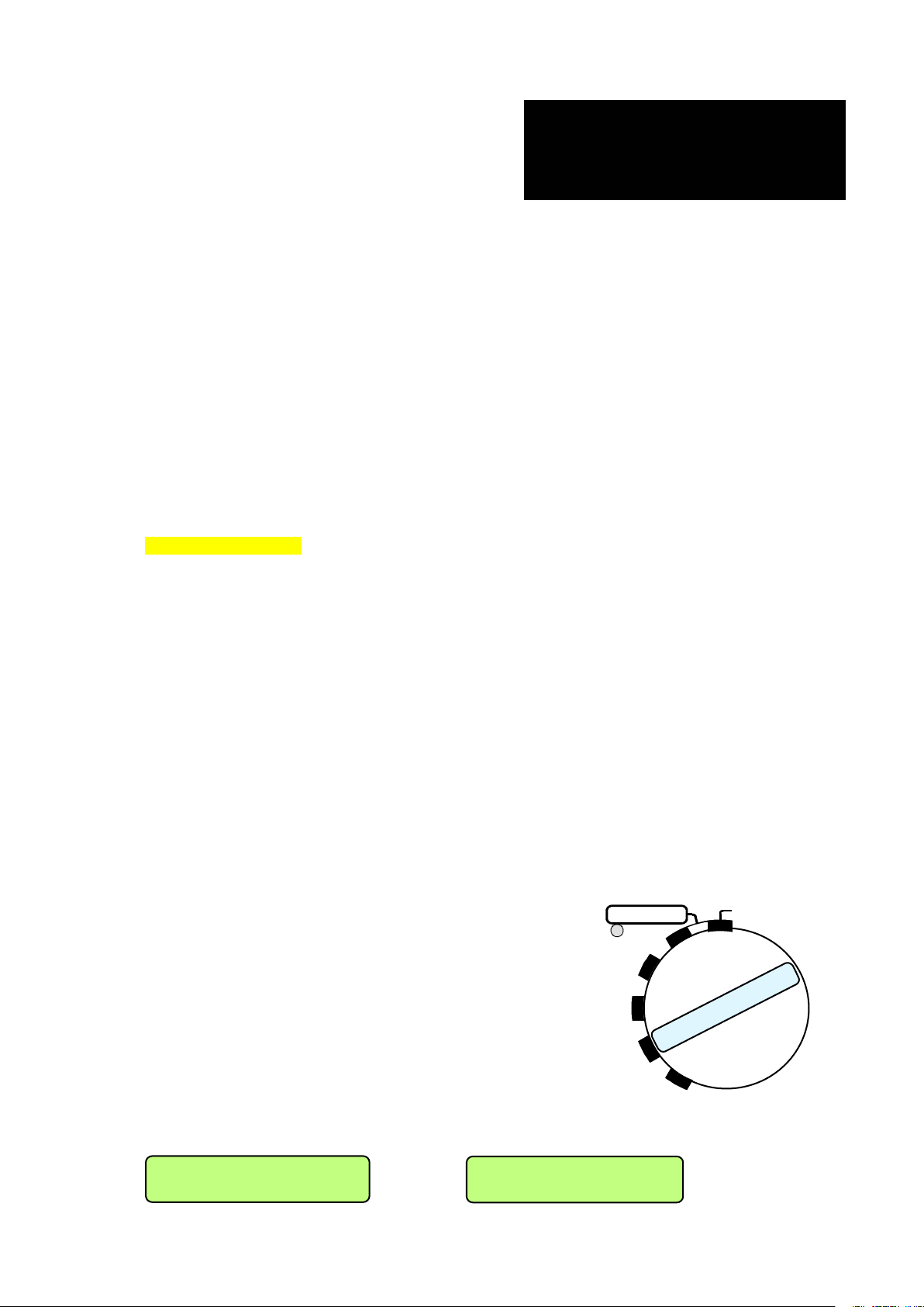
- 7031 130 000 NV-LIM: Internal audio limiter for mike
OR
Set L o s t
inputs
- 7031 145 000 NV-96K: High sampling frequency option
- 7031 100 000 NV-COM: PC software for Nagra-V
(requires ND-PCA RS 232 / 422 adapter # 7010 540 000)
A full list of available accessories can be found at the end of chapter 6 of this manual.
3.0 FIRST REQUIREMENTS
3.1 IF THE NA-BB8B BATTERY BOX IS AVAILABLE
Remove the battery box (type 8 D cells) from the NAGRA-V by lifting the two grey side levers upwards on
the left and right rear sides.
Open the battery box by pushing together the two finger shape plastic clamps and remove the top cover.
Install 8 dry cells type D or 8 fully charged NiCd or NimH type D cells taking care of the polarity indicated
and refit the cover.
Re-install the battery box on the rear of the NAGRA-V and lock the two grey levers.
Jump to paragraph 4.0
3.2 IF THE NV-LIB (Lithium Ion) POWER PACK AND THE AC SUPPLY NV-PSU ARE
AVAILABLE
Install the Lithium Ion box with or without the Lithium Ion pack on the Nagra-V and lock the two grey levers.
Connect the DC connector. Connect the AC power supply to the AC outlet. Once this is done, a green led
must light on the NiCd power pack, indicating that a correct DC voltage is received from the AC power
supply. If the red light comes on, disconnect the battery compartment from the NAGRA v and the red light
will go off and the green light will come on.
3.2 IF ONLY A 4 PIN EXTERNAL DC SUPPLY IS AVAILABLE
Connect the external 12V supply to the four pin XLR connector located behind the battery box on the rear of
the machine.
4.0 SWITCHING ON FOR THE FIRST TIME
Verify that the MAIN selector knob on the front right side of the
NAGRA-V is set to STOP (horizontal position).
The NAGRA-V will not switch on if new batteries have been installed
and the main selector was not in the STOP position. Set to
STOP after changing the batteries, then wait a few seconds before
switching ON again.
This is also valid if a Lithium Ion battery pack was used in place of
the standard battery box.
After a few seconds, set the MAIN selector to TEST. The display
of the NAGRA-V will show Booting for about 20 seconds. After this,
if a HDD was already inserted, the display will scroll through the
main settings of the NAGRA-V.
RECOR D
TE S T
STOP
STD.
BY
PLA Y
NOA.L.C./LIM.
If no HDD was inserted in the NAGRA-V, the display will show Set Lost or No Disk (see paragraph 6.0).
QUICK START 5 May 2003
N o D i s k
Page 86
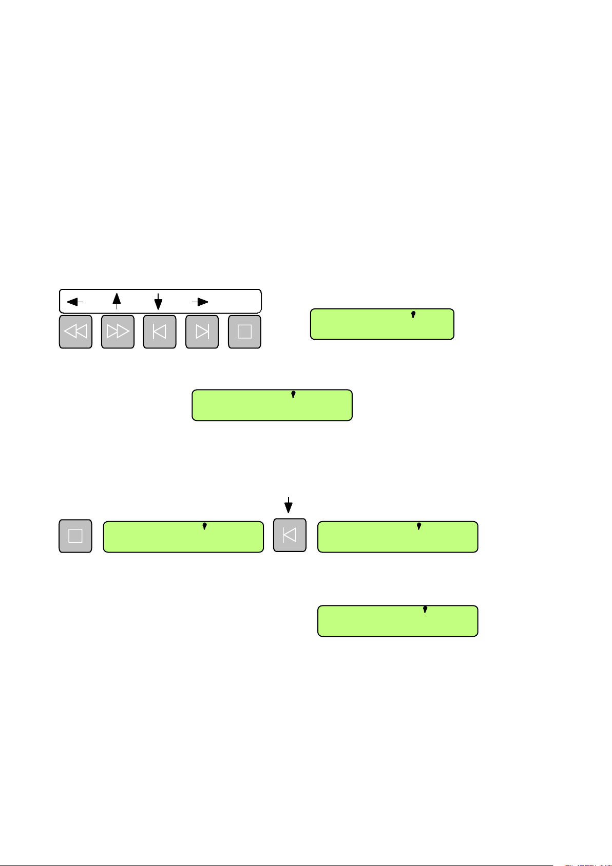
Set Lost appears when the machine was stored without a battery connected to it for a long time. In this
Power
case, the machine has lost all internal user selected settings.
By pushing the BATT switch, located on the bottom left corner of the front panel, the modulometer will
indicate the voltage level (the needle must be in the green area). If this voltage drops below the minimum
voltage, the NAGRA-V will automatically switch off.
5.0 SETTING TIME AND DATE OF THE REAL TIME CLOCK (RTC)
Set the Main function selector on the front panel to the STD.BY position. The Nagra-V must have a HDD
drawer inserted before power ON.
Press the shift key twice and verify that the Flag 1 is lit.
This activates the menu mode to go through the settings of the machine using the arrows above the scroll
keys.
EXE
Start to scroll downwards until OTHER appears on the display. Scroll once to the right until Date Time
appears. The next scroll to the right side shows Time. Again one step to the right shows the following
display: (example)
Video
TCExt
TCInt
Lock
000 000
.
Flag 1
.
Flag 2
Flag 3
T 00.02.34
The RTC will be incrementing. Do not confuse this clock with the optional Time Code clock. The format of
the RTC is according to the international 24Hr format of HH.MM.SS
The first digit starts blinking. By using the up or down arrow keys the correct hour can be adjusted.
By using the right arrow key the next digit starts blinking. Continue the adjustments until the seconds are
entered and press the EXE key. The following display appears again:
EXE
T ime Date
To find the Date menu, push the down arrow key once. Repeat the same principals as for the time
settings.
As an example this display shows June 26th, 2002
26.06.2002
Please note that the date format corresponds to the DD.MM.YYYY format.
QUICK START 6 May 2003
Page 87
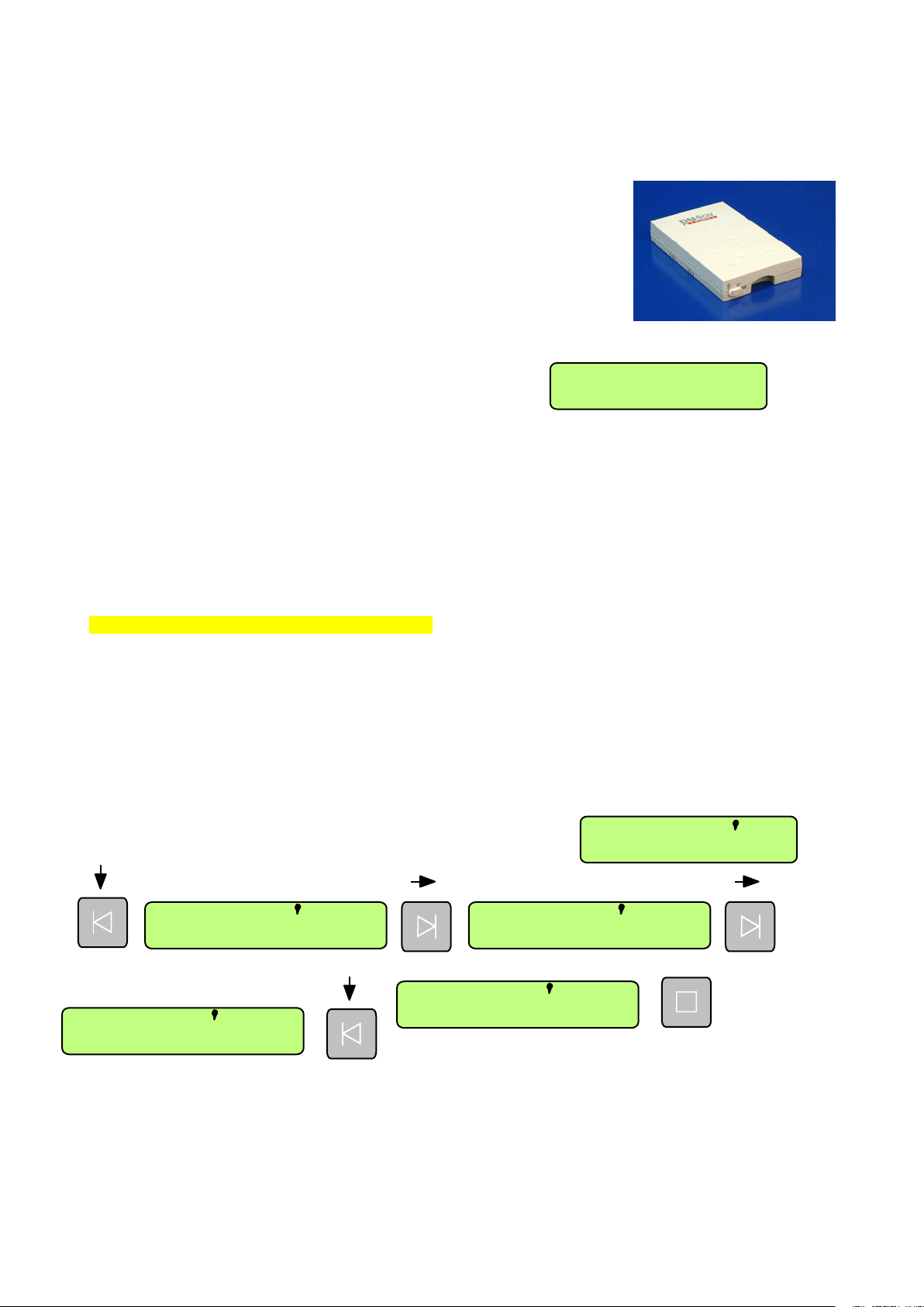
6.0 INSTALLING THE HDD FOR THE FIRST TIME
Power
6.1 HDD DRAWER
Insert the HDD drawer, taking care that the Nagra-V as well as the power
switch on the drawer is OFF. Once fully inserted, turn ON the drawer power
switch. This automatically secures mechanically the drawer inside the bay
and turn ON the Nagra-V.
Attention: The HDD must be formatted FAT 16 (Max. 1GB) or FAT 32 DOS.
All other formats are not accepted.
Once the cartridge is inserted and the machine is switched ON, the led on
the drive starts blinking red, green. After about approximately 30 seconds, the led should become green
and the No Disk on display will be replaced by:
This indicates actually 0 recordings on the cartridge.
000 000
.
.
7.0 MAKING THE FIRST RECORDING USING 1 MICROPHONE
If it is preferable to go through the settings later and the machine showed Date Lost, the Nagra-V has the
following factory settings:
MASTER, 48 KHZ, BWF 24, ANALOG, POT. OUT, LEV. AUTO, LINE OUT, SPK. AUTO.
LEV. AUTO will not appear if the modulometer was set before the line output potentiometer (factory
standard setting for the box motherboard 9131 300 000 B)
In this case when making a recording with one microphone, only the left or the right channel will be
recorded.
For recording immediately, jump to paragraph 7.4.
7.1 MICROPHONE CONNECTION CONFIGURATION
Connect a microphone to the left Mike input. Depending on the type of microphones used, select with the
switch above the Mike connector the corresponding power supply (dyn., T12 or Ph+48).
7.2 MICROPHONE INPUT CONFIGURATION
SOURCE selection.
Double click the SHIFT button and verify that Flag 1 is highlighted.
Click the down arrow key several times until Input appears etc.
Video
TCExt
TCInt
Lock
000 000
.
Flag 1
Flag 2
.
Flag 3
Input Source
EXE
ANALOG
AES
QUICK START 7 May 2003
Page 88
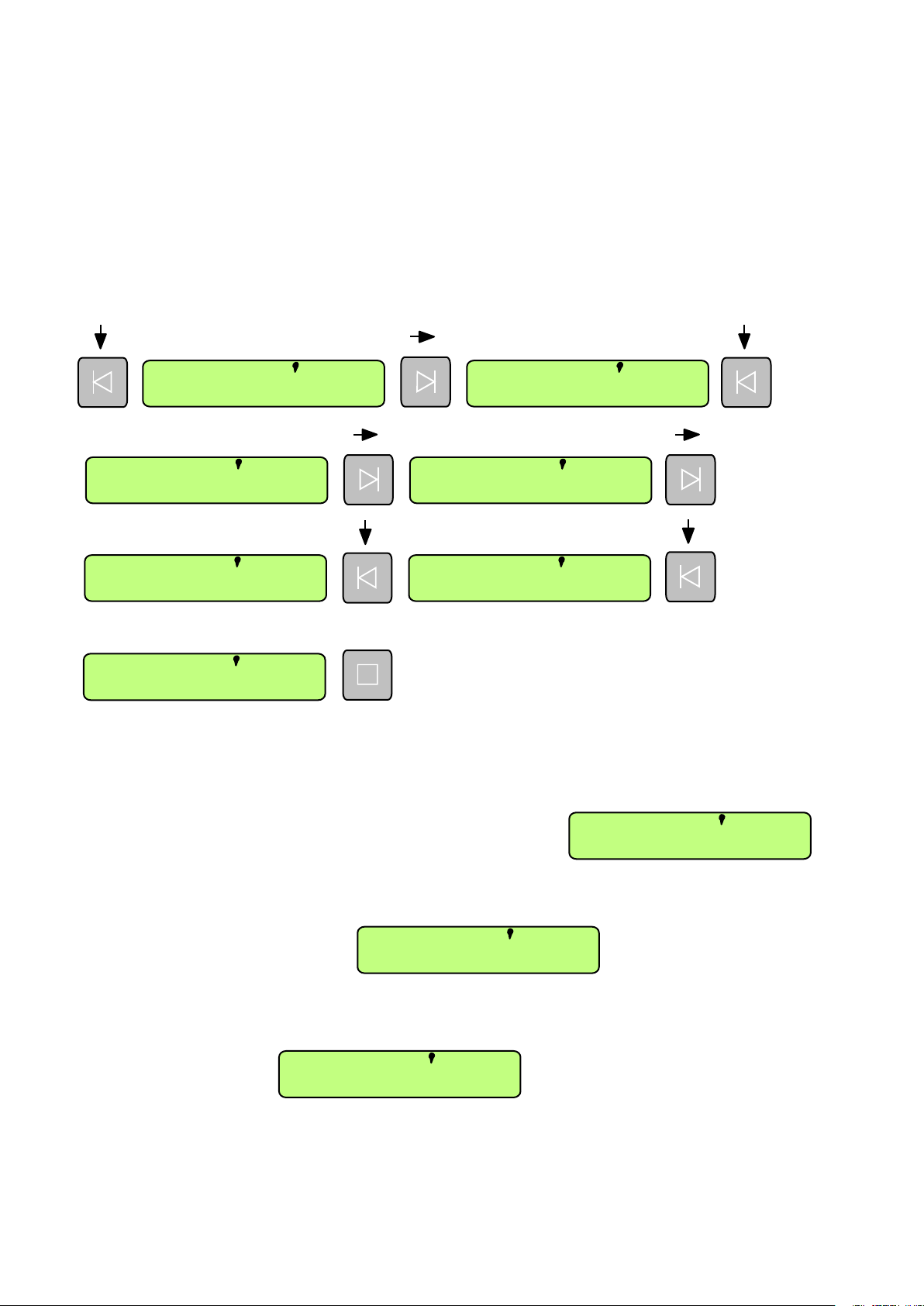
Once ANALOG found, push the EXE button.
Important: ONLY displays appearing in CAPITAL LETTERS can be executed.
Depending upon previous settings, the first executable display that appears is the one for which the NagraV was already set. Example: In the case above, the AES display came first, so the machine was set to
AES input.
To go backwards in the scrolling use the left, up and down arrow keys.
To leave the menus, press the SHIFT key or move the main selector.
MATRIX (ROUTING) SELECTION
As the microphone is connected to the left Mike input, the routing should be that left and right channel will
record the left Mike. Follow next steps. Click the down arrow key until Input is displayed:
Input Source
Matrix Mike L
LEFT RIGHT
EXE
BOTH
Repeat the same steps for the Mike R and select this time OFF followed by execute.
Also in the Matrix menu, repeat the same steps for the line input Aux L and Aux R and also select
OFF followed by execute.
REFERENCE FREQUENCY (internal clock generator)
Scroll through the menu until Ref. Freq appears, scroll one step to the right and by scrolling up or down,
select MASTER and execute.
SAMPLING FREQUENCY
Scroll through the menu until Sam. Freq appears, scroll one step to the right and by scrolling up or down,
select 48 kHz and execute.
48 KHZ
MASTER
MODULOMETER
The modulometer indication can be selected to be active for the input level or for the output level. In the
case of recording a signal, it is advised to set this selection to automatic. If the Modulom. is not
appearing, it is because the machine is equipped with the box motherboard 9131 300 000 B and the
modulometer is by hardware configured before the line output potentiometer.
QUICK START 8 May 2003
LEV. AUTO
Page 89

Scroll through the menu until Modulom, appears, scroll one step to the right and by scrolling up or down,
STEREO
.
.
select LEV. AUTO followed by execute.
LINE POT. ASSIGN SELECTION
The next selection that needs to be made is the choice for the AUX. IN & LINE OUT potentiometer. As the
Line input is not used, the selection can be output adjustment only or selective combined with the SHIFT
key.
Scroll through the menu until Line Pot appears, scroll one step to the right and by scrollling up or down,
select POT. OUT and execute.
MONITORING SELECTION
Scroll through the menu until Monitor appears, scroll one step to
the right and by scrolling up or down, select Mode followed by
STEREO and execute.
Scroll through the menu until Monitor appears, scroll one step to
the right and by scrolling up or down, select Source followed by
LINE OUT and execute.
Scroll through the menu until Monitor appears, scroll one step to
the right and by scrolling up or down, select Loud. Spk followed by
SPK. AUTO and execute.
This selection is simular to the modulometer. During record or test, the speaker is automatically switched
off and durng play or edit, it is switched on.
POT. OUT
LINE OUT
SPK. AUTO
FORMAT
Scroll through the menu until Format appears, scroll one step to the right and by scrolling up or down,
select BWF 16 and execute.
TAKE NUMBER AND TAKE LENGTH INDICATION
BWF 16
000 000
Once leaving the menus, by pushing the SHIFT key once, the main
display can show different types of information. Time Code, remaining time, take number and delta TC.
To select one push twice the SHIFT key to highlight the flag 1. Push the right or left arrow key untilTAKE
appears and execute.
7.3 SETTINGS CHECK
To check if all main settings just executed are correct, it is easy to recall them by just pushing the
modulometer switch BATT a single time downwards and the display will scrollthrough them.
The list appearing on the display will be the following:
MASTER, 48 KHZ, BWF 16, ANALOG, POT. OUT, LEV. AUTO, LINE OUT, SPK. AUTO
LEV. AUTO will not appear if the modulometer was set before the line output potentiometer (factory
standard setting for the box motherboard 9131 300 000 B)
QUICK START 9 May 2003
Page 90

7.4 MICROPHONE LEVEL ADJUSTMENT IN TEST MODE
Verify that the EE, AUTO, TAPE selector is in the AUTO position.
Verify first of all that the modulometer selector (below the meter) is in the middle position (max.) and the
next selector to the right is in the NORM position.
While speaking into the microphone, adjust the left MIKE LEVEL
potentiometer until the meter is oscillating close to the -6dB mark.
If this is not possible, change the position of the corresponding
SENSITIVITY (1mV/hPa, 4mV/hPa, 0.2mV/hPa) selector below
the potentiometer. The sector from -6 dB to 0 dB is the
headroom area for the AD converter. This means that the input
signal may be increased with max. 6 dB before the AD converter
starts to saturate.
7.5 HEADPHONE CONTROL
Connect a stereo headphone to the jack connector. Adjust the front AUX. IN & LINE OUT potentiometer to
approx. 0dB on the potentiometer scale. While speaking in the microphone, adjust the phones level
potentiometer (next to the headphone jack connector) to obtain a correct headphone level.
7.6 RECORD
Put the main selector in the RECORD position. Automatically the red led on the front display will light.
This indicates that the NAGRA-V is in the record mode. The display shows the number 001 on the left side
which indicates the take number and on the right side an increments counter indicating in minutes and
seconds the instantaneous length of the recording in progress.
To stop the recording, set the main selector back to the TEST position. The display now shows the take
number 001 on the left side and 000 on the right side (beginning of take when starting playback).
7.7 RECORD WITH MARKERS
Now that the first recording has been made, let us try a second one in which a marker will be inserted. Set
the main selector back to RECORD and observe that the take number on the display now indicates 2
instead of 1. Simultaneously, on the right side of the front display, the counter restarted from 000. At the
moment that a marker needs to be inserted during record, just push the button once (below the EXE
sign) and automatically take 3 starts. During playback of take 2 and 3 afterwards, no interruption will be
detected.
8.0 PLAYING BACK FROM THE FRONT PANEL
During a record session, it happens sometimes that a short playback of the last part of a take or a previous
take is asked.
Once the recording has been finished, the main selector can be immediately set to the PLAY mode.
Instantaneously, the last recorded take will be played back
from the beginning (counter 000). By using the function keys,
it becomes possible to start the same take over, to skip to
previous takes as well as playing back at four times the nominal speed forwards or backwards. This time,
the function keys themselves, are active rather than the features indicated in the rectangular box above the
keys.
The single left arrow button permits, if briefly pushed, to start the play of the same take from the beginning.
The single left arrow button also permits, if pushed twice, to skip to the beginning of the previous take and
playing back immediately.
The single right arrow button permits, if pushed briefly, to skip to the next take and play back immediately.
The double right arrow button permits to playback the take at 4 times the nominal speed.
The double left arrow button permits to reverse playback the take at 4 times the nominal speed.
QUICK START 10 May 2003
Page 91

If a PAUSE is needed during playback, just put the main selector to the STB.BY position or push the
STOP button once. The playback stops automatically and will restart from the same point once the main
selector is set back to the PLAY mode or the "STOP button is pressed again.
9.0 STARTING THE NEXT RECORDING AFTER PLAYBACK
If suddenly during playback of any recorded take, a new recording needs to be started immediately, just put
the main selector back to RECORD without worrying were the playback was located. No previous
recordings can be accidentally erased by doing this. The new recording will start from the end of the last
recorded take located on the card.
QUICK START 11 Oct 2002
 Loading...