


IV-SJ
I
I
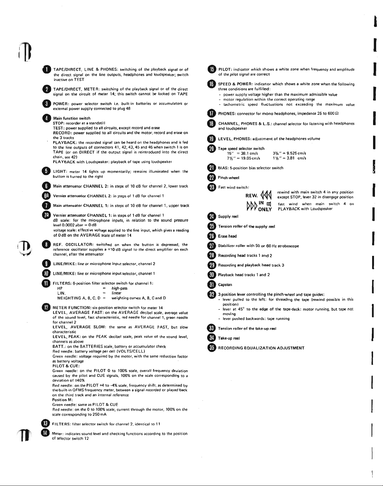
• TAPE/DIRECT, LINE&PHONES: switching of the playback signal o~ of
the direct signal on the line outputs, headphones and loudspeaker; switch
inactive on TEST
• TAPE/DIRECT, METER: switching of the playback signal or of the direct
signal on the circuit of rIleter 14; this switch cannot be locked on TAPE
• POWER: power selector switch i.e. built-in batteries or accumulators or
external power supply connected to plug 48
• Main function switch
STOP: recorder at • standstill
TEST: power sopplied to all circuits, except record and erase
RECORD: power supplied to all circuits and the motor; record and erase on
the 3 tracks
PLAYBACK: the recorded signal can be heard on the headphones and is fed
to the line outputs of connectors 41, 42,43,45 and 46 when switch 1 is on
TAPE (or on DIRECT if the output signal is reintroduced into the direct
chain. see 42)
PLA YBACK with Loudspeaker: playback of tape using loudspeaker
LIGHT; meter 14 lights up momentarily: remains illuminated when the
button is turned to the right
•
o
Main attenuator CHANNEL 2: in steps of 10 dB for channel 2,Iower track
• Vernier attenuator CHANNE L 2; in steps of 1dB for channel 1
• Main attenuator CHANN.E L 1: in steps of 10 dB for channel I, upper track
• Vernier attenuator CHANNE L 1: in steps of 1 dB for channel 1
dB scale: for the microphone inputs, in relation to the sound pressure
level 0.OOO2pbar=0 dB
voltage scale; effective voltage applied to the line input, which gives a reading
of OdB on the AVERAGE scale of meter 14
REF. OSCILLATOR: switched on when the button is depressed, the
reference oscillator supplies a +10 dB signal to the direct amplifier on each
channel, after the attenuator
•
LINE/MIKE: line or microphone input selector, channel 2
LINE/MIKE: line or microphone input selector, channell
•
FI LTERS: 6-position filter selector switch for channell:
•
HP high·pass
L1N. linear
•
WE IGHTING A, B, C, D weighting curves A, B, C and D
METER FUNCTION: six-position selector switch for meter 14
lEVEL. AVERAGE FAST: on the AVERAGE decibel scale, average value
of the sound level, fast characteristic, red needle for channel I, green needle
for channel 2
lEVEL. AVERAGE SLOW; the same as AVERAGE FAST, but slow
characteristic
LEVEL, PEAK: on the PEAK decibel scale, peak value of the sound level,
channels as above
BATT.: on the BATTERIES scale, battery or accumulator check
Red needle: battery voltage per cell (VOLTS/CELL)
Green needle: voltage required by the motor, with the same reduction factor
as battery voltage
PILOT8o CUE:
Green needle: on the PILOT 0 to 100% scale, overall frequency deviation
caused by the pilot and CUE signals, 100% on the scale corresponding to a
deviation of ±40%
Red needle: on the PILOT +4 to -4% scale, frequency shift, as determined by
the built-in OFMS frequency meter, between a signal recorded or played back
on the third track and an internal reference
Position M:
Green needle: same as PILOT&CUE
Red needle: on the 0 to 100% scale, current through the motor, 100% on the
scale corresponding to 250 mA
Fll TERS: filter selector switch for channel 2. identical to II
CD
Meter: indicates sound level and checking functions according to the position
of selector switch 12
•
• PILOT: indicator which shows a white lone when frequency and amplitude
of the pilot signal are correct
SPEED&POWER: indicator which shows a white lone when the following
three conditions are fulfilled:
- power supply voltage higher than the maximum admissible value
- motor regulation within the correct operating range
tachometric speed fluctuations not exceedinq the maximum value
«I»
PHONES: connector for mono headphones, impedance 25 to 600n
• CHANNEL, PHONES&L.S.: channel selector for listening with headphones
and loudspeaker
• LEVEL, PHONES: adjustment of the headphones volume
• Tape speed selector switch
• BIAS: 5'position bias selector switch
• Pinch-wheel
IS"=38.1 cmls
7'/,"
=
19.05cm/s
6)Fast wind switch:
REW.
• Supply reel
• Tension roller of the supplV reel
• Erase head
•• Stabilizer roller with 50 or 60 Hz stroboscope
• Recording head tracks 1 and 2
e.
Recording and playback head track 3
•• Playback head tracks 1 and 2
CD
Capstan
• 3'position lever controlling the pinch-wheel and tape guicles:
. - lever pulled to the left: for threading the tape (rewind possible in this
position)
- lever at 45° to the edge of the tape-deck: motor running, but tape not
moving
- lever pushed backwards: tape running
•• Tension roller of the take-up reel
• Take·up reel
3% .•=9.525 cm/s
1
'h"
=
3.81 ·cm/s
rewind with main switch 4 in any position
except STOP, lever 32 in disengage position
fast wind when main switch 4 on
PLAYBACK with Loudspeaker
6)RECORDING EOUALIZA TION ADJUSTMENT
I
I
I
I
I
I
I
I
I
I
I
I
I
I
L-J
l-j
I
[ J
I
~]
[I~
~J
[[=
~~
.--
.L
J
]
J
J
]
Direct analysis of sound signals
Used solely as an amplifier the NAGRA IV-SJ is a
precision sound level meter, which operates with
any calibrated microphone cartridge. The sound
pressure measurements must be taken in relation to
the
0
dB reference level, which corresponds to a
pressure of 0.0002 ubar, i.e. 20
This level coincides in practice with the audibility
threshold of the human ear at
quency, the sound level can be expressed in phones,
the phones value being equal to the dB value read
in relation to the 0.0002 /-Ibarreference.
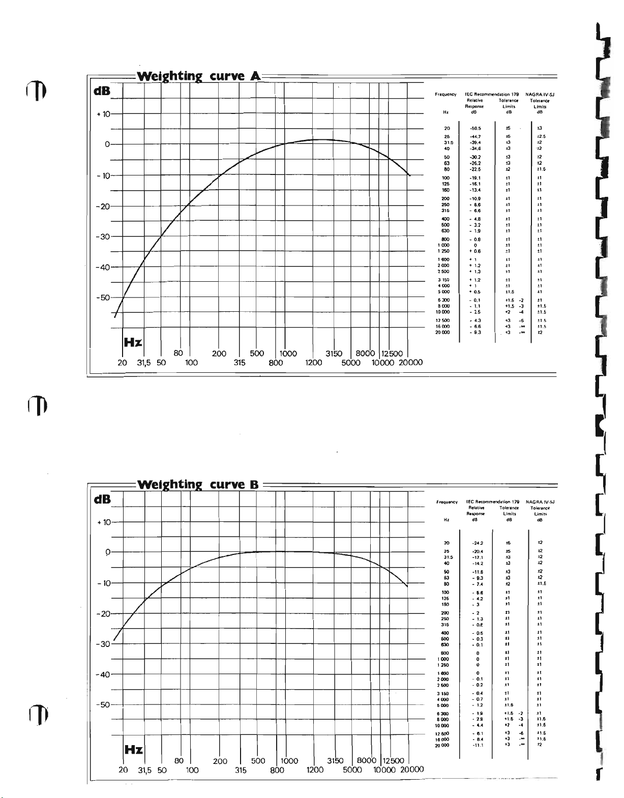
'.The frequency response of the human ear is not
linear and depends very much on the sound level; a
sound level meter must therefore include weighting
filters which modify the values measured in accordance with certain criteria, so that they can be
interpreted in relation to the subjective impression
felt by the human ear. There are three standard
weighting curves, A, Band C. Curve A is used for
low and medium sound levels, which are the subject of most analyses; curves Band C relate to
higher levels. Curve D relates to contour-lines of·
perceived noisiness, in particular with noise pro-
duced by aviation: this weighting is used for the
measurement of sounds which cause annoyance
in general. Curves A, B, G and D are shown after
the specifications.
The sound level measured is shown on a dual
galvanometer. with one needle per channel. Its
measuring circuit determines the average value of
the signal on RMS and its peak value on
PEAK, with different dynamic characteristics in
relation to the integration time. On RMS
FAST integration time is 200 ms: a signal at
lasting 200 ms gives a reading
which would correspond to the steady signal. On
RMS SLOW, integration time is 500 ms and
a signal lasting 500 ms gives a reading 4 dB below
that which would correspond to the steady signal.
These two integration times are in accordance with
J.lN/m2or 20 J.lPa.
1 kHz; at this fre-
1 kHz
1 dB lower than that
INSTRUCTION MANUAL
I
the GEl standard 179 for
meters. Naturally, any signal which is shorter than
the integration time will be shown below its real
value. For analysis of pulse signals or strong
transients a more useful reading is obtained on
PEAK, i.e. peak value with an integration time of
5
only
because it causes visual fatigue: in order to overcome this disadvantage the measuring circuit holds
the signal for about one second, thereby increasing
the fall time of the needle.
Recording and playback of the sound signals
In all cases where direct. measurement is not
sufficient for studying the signals picked up by the
microphone, these signals can be recorded on magnetic tape and analyzed later in the laboratory.
While the two tracks used for direct recording are
in use, the third track
synchronization, a commentary, or a measuringsignal from D.C. up to 4 kHz. The three tracks
thus store signals in fully-synchronized form, which
is an important factor for analysis.
However, this storage is restricted to some extent
due to the limitations of present magnetic tapes.
These limitations concern the following charac-
teristics in particular:
the response curve
Attenuation at the upper and lower extremes of
the spectrum depends on the speed used. Very low
frequency signals, which are difficult to play back
with a small reproduce head, should be analyzed
by frequency transposition.
distortion
This increases very rapidly as soon as the maximum
recording level is exceeded, and tape saturation
occurs, generating harmonic frequencies (in
ticular 2nd and 3rd harmonics), which falsify the
analysis of the signals.
ms. This very fast reading cannot be used
Measurements
precrsion
C'IO
record F M signals for
sound level
par
I
crosstalk
The juxtaposition of the two channels inside the
recording head and the playback head produces
crosstalk. This is the ratio, at a playback amplifier
output. between the wanted signal and the unwanted signal from the other channel. Crosstalk
increases at high frequencies.
The maximum peak level, which corresponds to a
tape flux of 32 mM/mm, is reached when the
measuring instrument shows
RMS scale and +20 dB on the PEAK scale.
These two values are given in relation to the sound
·pressure reference level 0 dB
0.0002J.1bar.
On RMS the integration time of the
measuring circuit is long enough not to indicate
short pulses at their exact value and risk exceeding
the maximum recording level, thereby saturating
the tape. That is why, on RMS , the maxi-
+
10
mum level is given at
the signals with strong pulse content saturating the
tape too Quickly.
In all cases where the nature of a signal is not
obvious it should be recorded with the measuring
circuit on PEAK, which is the only way to make
the peak value of very short pulses visible and to
avoid their exceeding the maximum recording level.
Frequency transposition
Playback speed may be different from recording
speed: this produces a frequency transposition of
the signals recorded within the ratio of these two
speeds. Since the response curve in the low frequencies is limited to
possible, if the tape transport speed is ten times
faster on playback than on recording, to play back
frequencies which are ten times. lower. Thus, a
2.5 Hz signal recorded at 1.5 ips will have a fre·
quency of
(transposition
conventional equipment. In the same way, the
time needed to analyze signals which vary very
slowly is reduced in the same ratio by this process.
Conversely. it is possible to analyze in more detail
a signal which varies rapidly by playing it back
more slowly than it was recorded. However, in
both cases, care must be taken that the transposition does not alter the signals in any way, taking
into account the limitations of the frequency res-
ponse at the speeds used.
25 Hz if it is played back at 15 ips
1: 1
0), and can be analyzed easily by
dB: the10dB lead avoids
25 Hz on playback only, it is
+10 dB on the
=
20 pPa or
I
I
I
I
I
I
I
I
I
I
I
I
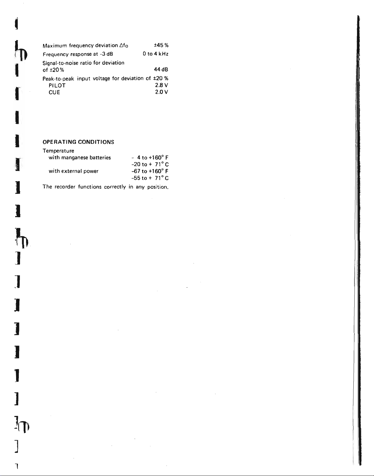
Maximum frequency deviation t>fo
Frequency response at
Signal-to-noise ratio for deviation
of ±20%
Peak-to-peak input voltage for deviation of ±20
PILOT
CUE 2.0 V
-3 dB
o
to 4 kHz
±45%
44dB
2_8 V
%
I
I
I
I
]
]
J
OPERATING CONDITIONS
Temperature
with manganese batteries
with external power
The recorder functions correctly in any position.
- 4to+160°F
-20to+ 71°C
-67 to +160
-55 to
+
0
71 °C
F
]
I
)
]
1
dB
+10
-10
-20
-30
-40
-50
Wei21
ht'
0
.I
/
I
/
/
/
J
I
In2
V
curve
/
A
Ffequency lEe Recommendation 179
/
./
./
.•...•.
!'-..
<,
10000
'2500
'6000 - 6.6 +3
20000
Rt'I.tI~
Respome
H,
20
25
31,5
40
SO
63
80
'00
'25
'60
200
250
3'5
"""
500
630
800
1000
1250
1600 + I
2000
2500
3150
4000 + 1
5000
6300
8000
dB
·50.5
-" •. 7
-39.4
-34.6
-30.2
-26.2
-22.5
-'9.1
-16.1
-13.4
-10.9
- •. 6
- 6.6
- ".8
- 3.2
- 1.9
- O.S
.•. 0.6
+ 1.2
.• 1.3
+ 1.2
-+
- 0.1
-1.1
- 2.5
- 4.3
- 9.3
0
0.5
Tolrnn~
limitl
dB dB
,.
••
oJ
oJ
oJ
±3
12
11
t'
.,
.,
11 11
11
11
±,
.,
.,
±1
"
"
.,
"
et
et
!.1.S
+1.5
+1.5
+2
+3 -6
+3
N"GRAIV.sJ
-2
-3
..
_M
_M
Toler.nee
lImln
!3
:!:2.S
.,
.
.,
.,
t2
11,5
t,
11
11
l'
.,
t,
11
11
11
11
11
et
11
.,
.,
11
11
.,
%1.5
11.5
11.5
1:1.5
t2
Hz
20
80
50 100 315
31,5
200
500
1000 3150 8000 12500
800
1200
5000 10000
20000
dB
+10
-10
-20
-30/
-40
-50
Wet21 n2
hti
0
./
/
/
V
20
Hz
31,5 50
80
./
100
»>
curve
~
200
B
500 1000
315
800
-r---.
.•...•.
8000
3150
12500
1200 5000 10000
<,
20000
frequency
H,
20
25
31.5
40 -14.2
SO
63
eo
100
120
ISO
200
260
316
"""
600
830
800
, GOD
1260
1e00
2000
2500
3160
4000
6000
8_
8000
10000
12500
18000
20000
tEe Aecommmdation 1N
A.I.live
Response
Toleranoe
limits
d8
·242
-20.4
-17.1
-u.s
- 9.3
- 7.4
- 5.e
- 42
- 3
- 2
- 1.3
- D.e
- 0.5
- 0.3
- 0.1
- O.t
- D.2
- 0."
- 0.7
- 12
o
-a
- 4."
- 6.1
- 8.4
-11.1
_.-._--------_.
0
0
0
0
1.8
dB dB
••
15
13 12
03
03
03
12
., .,
.,
"
.,
11
.,
11 11
.,
.,
tI
at
.,
.,
"
.,
11 11
"
.11.5
.1.5
1-t.fI
'2
+3
+3
+3
NAGAAIV·SJ
-2
-3
-4
-6
--
--
To~nlnce
limite
12
12
12
t2
12
:1:1.6
11
"
et
"
11
.,
11
11
11
.,
.,
11
11
11
11
.,
.11.5
i1.6
11.6
il,6
"
---
r
t
ln
I
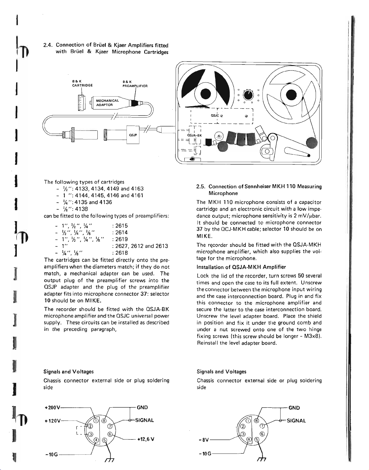
2.4. Connection of Brliel&Kjaer Amplifiers fitted
with Brliel
&
Kjaer Microphone Cartridges
I
I
I
J
I
I
I
J
]
I
]
I
B&K
CARTRIDGE
~
The following types of cartridges
- 'h";4133,4134,4149and4163
- 1 ";4144,4145,4146and4161
- 1,4";
- 1/8";
can be fitted to the following types of preamplifiers:
- 1",
- '12
- 1",
- 1" : 2627, 2612 and 2613
- 1,4",
The cartridges can be fitted directly onto the preamplifiers when the diameters match; if they do not
match, a mechanical adapter can be used. The
output plug of the preamplifier screws into the
OSJP adapter and the plug of the preamplifier
adapter fits into microphone connector
10 should be on MI KE.
The recorder should be fitted with the QSJA-BK
microphone amplifier and the QSJC universal power
supply. These circuits can be installed as described
in the preceding paragraph,
4135 and 4136
4 138
1/2",
1,4" :
",1,4 ",
1/8" :
'12",
1,4",
1/8" :
%" : 2618
B&K
PREAMPLIFIER
261 5
2614
2619
37:
selector
---1
QJ
I
L --l:o... .1
~T-'
=-=1
I
I
QSJA-BK
I
I
='iJJ
==[J
~
2.5. Connection of Sennheiser MKH 110 Measuring
Microphone
The MKH 110 microphone consists of a capacitor
cartridge and an electronic circuit with a low impedance output; microphone sensitivity is 2 mV
It should be connected to microphone connector
37
by the QCJ-MKH cable; selector 10 should be on
MIKE_
The recorder should be fitted with the QSJA-MKH
microphone amplifier, which also supplies the vol-·
tage for the microphone.
Installation of aSJA-MKH Amplifier
Lock the lid of the recorder, turn screws 50 several
times and open the case to its full extent. Unscrew
the connector between the microphone input wiring
and the case interconnection board. Plug in and fix
this connector to the microphone amplifier and
secure the latter to the case interconnection board.
Unscrew the level adapter board. Place the shield
in position and fix it under tile ground comb and
under a nut screwed onto one of the two hinge
fixing screws (this screw should be longer - M3x8).
Reinstall the level adapter board.
IMbar.
I
J
.J
,
Signals and Voltages
Chassis connector external side or plug soldering
side
+200Y
+120V
r -
L_
-10G
,-----r-GND
+12,6V
Signals and Voltages
Chassis connector external side or plug soldering
side
~--..,.-- GNO
SIGNAL
-8Y------
-10G----~
,
,
I
,
3. DIRECT MEASUREMENT OF SIGNALS
3.1.
Position of the Controls
Set switch 1 on DIRECT: switch 2, which cannot
be locked in position, remains on DIRECT. Turn
main selector switch 4 to TEST: the circuits are
then switched on and will stabilize after about 10
seconds.
3.4.3. Low·level Signals on the Microphone Input
QSJA-BK AMPLIFIER
With selector
7A
on0dB
Turn the cartridge type selector 40 to the position
which corresponds to the diameter of the cartridge
used. On
become +40. +60 and +90dB, values inscribed in a
circle.
10
on MIKE, set vernier attenuator
1f.t ••
the positions of gain selector 39
3.2. Selection of Measuring Circuit
Set the METER FUNCTION switch on one of the
LEVEL positions:
- RMS FAST : average valu~ of the sig·
nal on the RMS' scale of meter 14,
integration time 200 ms.
I
I
I
- RMS SLOW : average value of the
signal on the same scale, but integration
time 500 ms.
- PEAK: peak value of the signal, on the
PEAK scale of meter 14, integration time
5 ms, with a memory circuit holding the
signal for about
The measuring circuit of the recorder should be
selected in accordance with the criteria given in
Section
3.3. Adjustment of the Monitoring Circuit
The signals can be monitored on the headphones
with switch
loudspeaker on PLAYBACK with Loudspeaker
(see 6.).
The mono headphones, impedance 50 to 600
plug into jack 17. The required channel can be
selected with switch
by potentiometer
screwdriver.
3.
4
in any position and with the built-in
1 second.
18
and the loudness regulated
19,
which can be adjusted with a
n.
I
3.4.
Choice of Sensitivity
3.4.1.
I
Set selector 10 on LINE, turn main attenuator 7
fully to the left, or on GND, set vernier attenuator
7A on 0 dB (CAL.),
High·level Signals on the Line Input
I
Switch on the signal source connected to the line
input. While watching meter 14, turn main attenuator 7 to the right until the red needle makes a
visible movement. Calculate the value measured as
described in paragraph 3.6.1.
3.4.2. High-level Signals on the Microphone Input
Same procedure as in the preceding paragraph, but
with selector
10
on MIKE.
Turn attenuator
If the needle moves noticeably beyond +20 dB
PEAK or +10 dB RMS , turn switch 39 to
+80 dB. If the needle is clearly below 0 dB, turn
switch 39 to +40 dB. Calculate the value measured
and take into account the restrictions described in
paragraph
QSJA-MKH AMPLIFIER
This amplifier has no gain selector or cartridge type
selector. The sensitivity can be determined by main
attenuator
AMPLIFIER FOR GENERAL
RADIO MICROPHONE
The amplifier for use with the GENERAL RADIO
microphone is the QSJA-BK; please refer to the
above instructions for using this amplifier.
3.5. Choice of Filter
When filter selector switch 11 is on LlN, the
quency response of the direct chainislinear at
:to.3 dB from 2.5 Hz to 35 kHz. Selector switch
should be set on one of the following positions
according to the kind of measurements being taken:
HP: high-pass filter, attenuation
WEIGHTING A, B, C, D: weighting of the
The HP position should be used systematically when
the measurement of signals is not extended to very
low frequencies: in fact, since these are inaudible,
they are likely to falsify results and, in some cases,
saturate the amplifiers. Furthermore, this position
eliminates very low frequency noise from the cartridge itself.
The weighting positions A, B, C and D are used, in
the case of noise measurement, to obtain a value
corresponding to the subjective impression felt by
the human ear (see Section 1).
7 to +20 dB and watch meter 14.
3.6.3.
7
only.
fre-
3
dB at
20 Hz, 12 dB per octave
frequency response as determined by
international standards, the exact value
of which is given at the end of the section
entitled Specifications.
11
/
I-I
i-
II
J
I-
The arrowhead opposite the +40 dB position on
attenuator
restrictions must be observed in order to avoid
saturation of the input circuits, when measurements
are taken by microphone, preamplifier and ampli-
fier.
The performance of the microphone cartridges and
input amplifier circuits is restricted by the occur-
rence of saturation phenomena which are produced
when the sound level measured becomes very high.
These phenomena may be detected by a trained ear
if measurements are being taken and monitored
simultaneously (see
exposed acoustically to the sound source. If the
phenomena pass unnoticed the measurement will
be incorrect. The only sure way to avoid saturation
and its consequences is to impose a limit on the
attenuator which directly follows the input circuits; when the attenuator is at this limit, any sound
signal which makes the needle of meter
to the right to its fullest extent, saturates the input
circuits and cannot be measured. In this case, the
amplifier gain must be reduced by turning its selec-
tor from +40 dB to +60 dB or from +60 dB to
+80 dB; if saturation still occurs on this position it
means that the output level of the transducer used
is too high. A less sensitive transducer should then
be used or an attenuator inserted between the transducer and the preamplifier.
7
is to remind the user that certain
3.3.).
and if the operator is not
14
deviate
3.6.3.1. Limits and Corrections with theOJPA
Preamplifier and
Same as below
G (preamplifier gain) same as for Brtiel
2619 preamplifier.
3.6.3.2.
When main attenuator
at +40 dB, there is no risk of saturation as long as
the needle of meter
+20 dB PEAK, with gain selector 39 on +40 or
+GOdB; when the latter is on +80dB (+90 dB fora
~" cartridge), the main attenuator may be set
beyond the +40 dB position as saturation then
depends only on the cartridge used and the corresponding preamplifier.
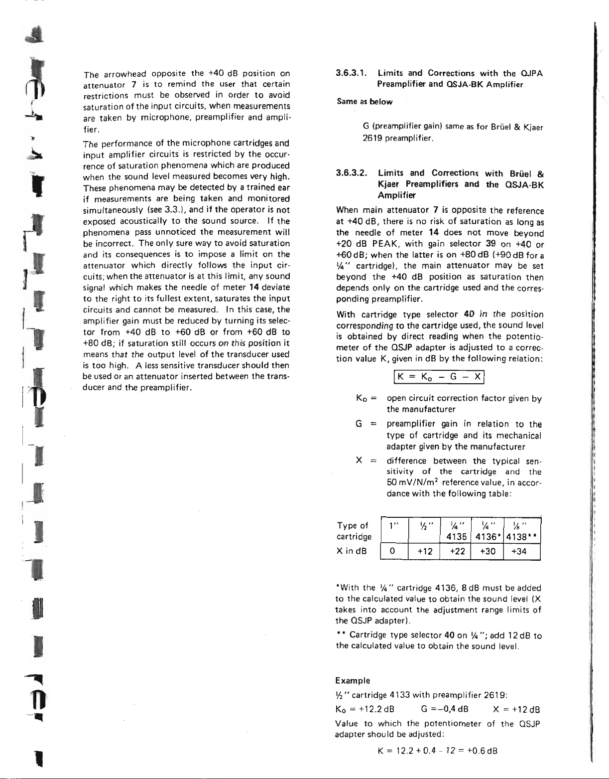
With cartridge type selector
corresponding to the cartridge used, the sound level
is obtained by direct reading when the potentiometer of the QSJP adapter is adjusted to a correction value K, given in dB by the following relation:
limits and Corrections with Brfiel
Kjaer Preamplifiers and the QSJA-BK
Amplifier
I
K=Ko - G - X
Ko==open circuit correction factor given by
the manufacturer
G
==
preamplifier gain in relation to the
type of cartridge and its mechanical
adapter given by the manufacturer
X difference between the typical sen-
sitivity of the cartridge and the
50 mV/N/m1reference value, in accor-
dance with the following table:
OSJA-BK Amplifier
7
is opposite the reference
14
does not move beyond
40
in the position
I
&
Kjaer
&
J
I
,
Type of
cartridge
X
in dB
*With the 1/4" cartridge 4136, 8 dB must be added
to the calculated value to obtain the sound level
takes into account the adjustment range limits of
the QSJP adapter).
**
Cartridge type selector 40 on 1/4 ": add 12 dB to
the calculated value to obtain the sound level.
Example
Ih"
cartridge 4133 with preamplifier 2619:
Ko=+12.2dB G=-O,4dB X=+12dB
Value to which the potentiometer of the QSJP
adapter shou Id be adjusted:
1"
K
=
'12 "
+12
0
12.2+0.4 - 12=+O.6d8
1,4 ••
4135 4136*
+22
'14"
+30
I/~"
4138"
+34
(X
t
p"-
-l
I
I
I
I
I
I
4. RECORDING OF SIGNALS
4.1. Choice of Tape
It is essential to use the type of magnetic tape for
which the recorder was adjusted at the factory; it is
only in this way that the values indicated in the
technical specifications {Section 2) can be obtained.
It is possible to use another type of tape by reo
adjusting the bias, equalization and recording level
. The performance obtained may
differ from the values shown in the test report
issued with each recorder; it is necessary to check
the results obtained with a new tape before using
the recorder for taking accurate measurements.
The positions of bias selector switch 21 correspond
to steps of 10%.
The length of the recording to be made is also a
determining factor in choosing the tape speed.
Place speed selector 20 on the position corresponding to the wanted speed; the speed can be switched
while the tape is running without damaging the
recorder.
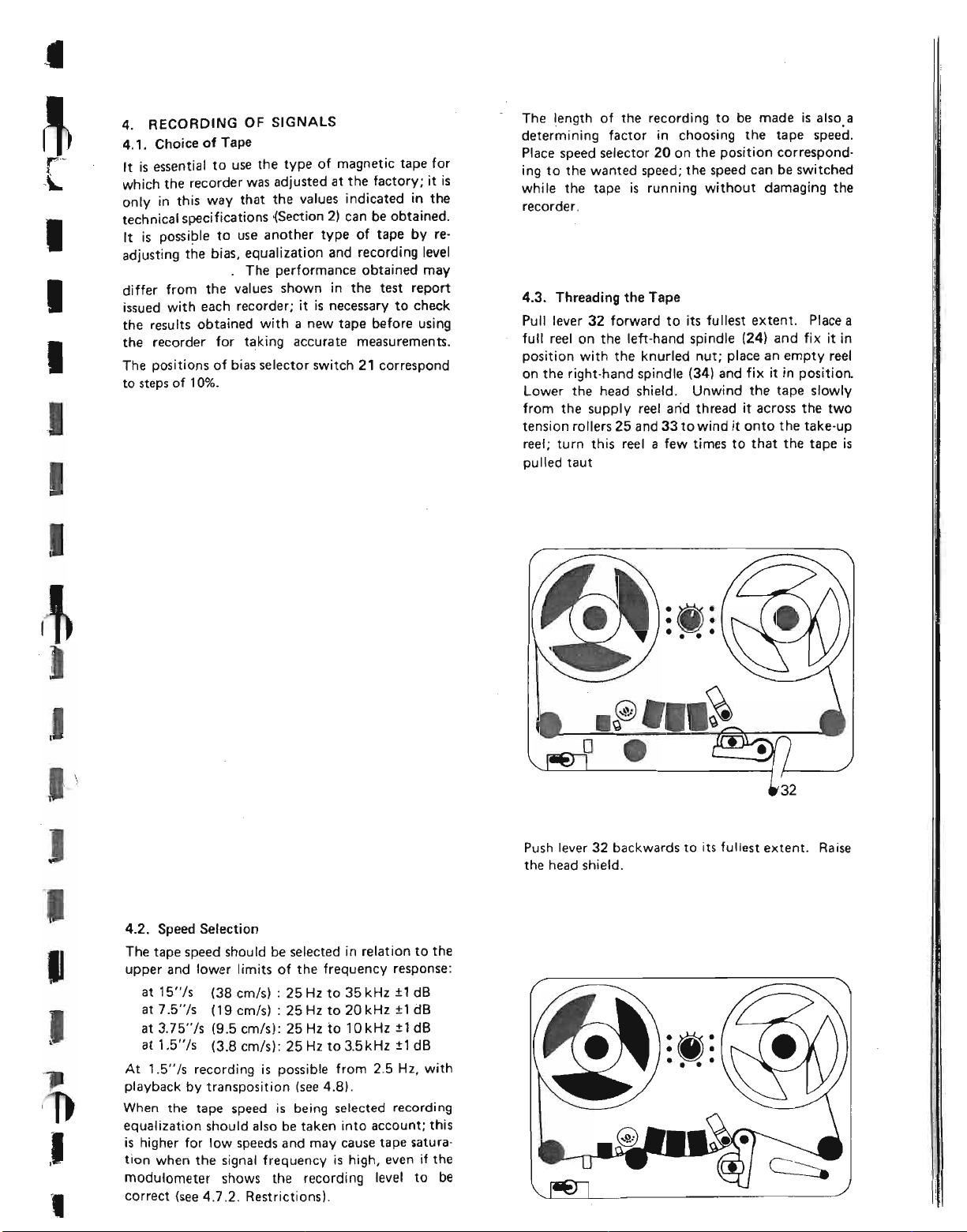
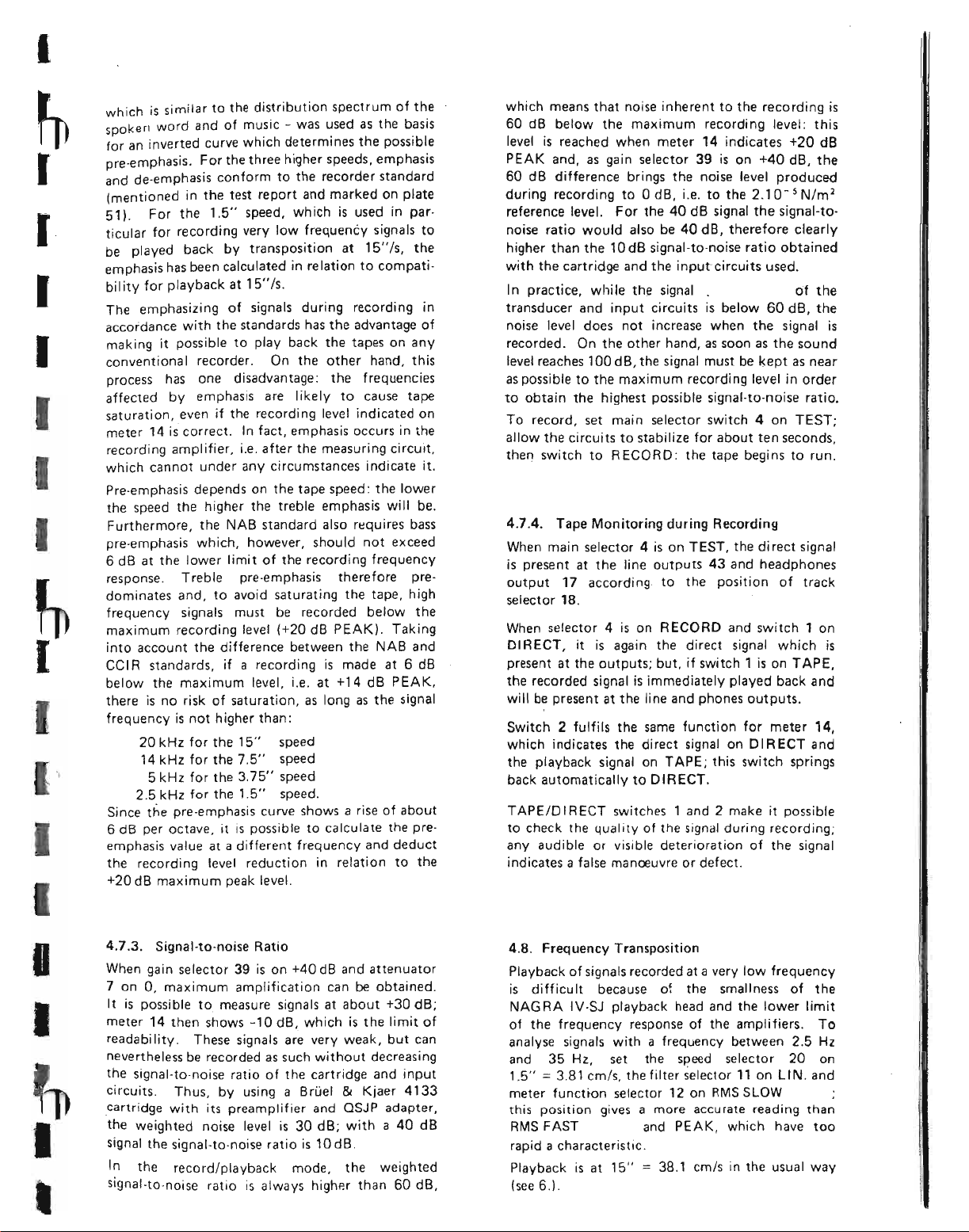
4.3. Threading the Tape
Pull lever 32 forward to its fullest extent. Place a
full reel on the left-hand spindle (24) and fix it in
position with the knurled nut; place an empty reel
on the right-hand spindle (34) and fix it in position.
Lower the head shield. Unwind the tape slowly
from the supply reel arid thread it across the two
tension rollers 25 and 33 to wind it onto the take-up
reel; turn this reel a few times to that the tape is
pulled taut
J
I
J
,
4.2. Speed Selection
The tape speed should be selected in relation to the
upper and lower limits of the frequency response:
at 15"/s (38 cm/s) : 25 Hz to 35 kHz ±1 dB
at 7.5"/s (19 cm/s) : 25 Hz to 20 kHz ±1 dB
at 3.75"/s (9.5 cm/s): 25 Hz to 10kHz ±1 dB
±
at 1.5"/5 (3.8 crn/sl: 25 Hz to 3.5 kHz
At 1.5"/s recording is possible from 2.5 Hz, with
playback by transposition (see 4.8).
When the tape speed is being selected recording
equalization should also be taken into account; this
is higher for low speeds and may cause tape saturation when the signal frequency is high, even if the
modulometer shows the recording level to be
correct (see 4.7.2. Restrictions).
1dB
:w:
••••
o •
Push lever 32 backwards to its fullest extent. Raise
the head shield.
I
I
I
I
I
~
I
I
I
which is similar to the distribution spectrum of the
spoken word and of music - was used as the basis
for an inverted curve which determi nes the possible
pre-emphasis. For the three higher speeds, emphasis
and de-emphasis conform to the recorder standard
(mentioned in the test report and marked on plate
51).
For the
I
I
ticular for recording very low frequency signals to
be played back by transposition at
emphasis has been calculated in relation to compatibility for playback at
The emphasizing of signals during recording in
accordance with the standards has the advantage of
making it possible to play back the tapes on any
conventional recorder. On the other hand, this
process has one disadvantage: the frequencies
affected by emphasis are likely to cause tape
saturation, even if the recording level indicated on
meter 14 is correct. In fact, emphasis occurs in the
recording amplifier, i.e. after the measuring circuit,
which cannot under any circumstances indicate it.
Pre-emphasis depends on the tape speed: the lower
the speed the higher the treble emphasis will be.
Furthermore, the NAB standard also requires bass
pre-emphasis which, however, should not exceed
6
dB at the lower limit of the recording frequency
response. Treble pre-emphasis therefore predominates and, to avoid saturating the tape, high
frequency signals must be recorded below the
maximum recording level (+20 dB PEAK). Taking
into account the difference between the NAB and
cel R standards, ifarecording is made at 6 dB
below the maximum level, i.e. at +14 dB PEAK,
there is no risk of saturation, as long as the signal
frequency is not higher than:
20
kHz for the
14 kHz for the 7.5" speed
5 kHz for the 3.75" speed
2.5
kHz for the
Since the pre-emphasis curve shows a rise of about
6 dB per octave. it is possible to calculate the pre-
emphasis value at a different frequency and deduct
the recording level reduction in relation to the
+20 dB maximum peak level.
1.5"
speed, which is used in par-
15"/5.
15"
speed
1.5"
speed.
15"
Is,
the
which means that noise inherent to the recording is
60 dB below the maximum recording level: this
level is reached when meter 14 indicates +20 dB
PEAK and, as gain selector 39 is on +40 dB, the
60
dB difference brings the noise level produced
during recording to 0 dB, i.e. to the 2.10- 5 Nlm
reference level. For the 40 dB signal the signal-tonoise ratio would also be 40 dB, therefore clearly
higher than the 10 dB signal-to-noise ratio obtained
with the cartridge and the input circuits used.
I
n practice, whi Ie the signal . of the
transducer and input circuits is below
noise level does not increase when the signal is
recorded. On the other hand, as soon as the sound
level reaches 100 dB, the signal must be kept as near
as possible to the maximum recording level in order
to obtain the highest possible signal·to-noise ratio.
To record, set main selector switch4on TEST;
allow the circuits to stabilize for about t~n seconds,
then
switch to RECORD: the tape begins to run.
4.7.4. Tape Monitoring during Recording
When main selector4is on TEST, the di rect signal
is present at the line outputs 43 and headphones
output
selector
When selector
DIRECT, it is again the direct signal which is
present at the outputs; but, if switch 1 is on TAPE,
the recorded signal is immediately played back and
will be present at the line and phones outputs.
Switch 2 fulfils the same function for meter 14,
which indicates the direct signal on DIRECT and
the playback signal on TAPE; this switch springs
back automatically to DIRECT.
TAPE/D IR ECT switches 1 and 2 make it possible
to check the quality of the signal during recording;
any audible or visible deterioration of the signal
indicates a false manoeuvre or defect.
17
according to the position of track
18.
4
is on RECORD and switch1on
60
dB, the
2
I
I
I
~
I
,
4.7.3.
When gain selector 39 is on +40 dB and attenuator
7 on 0, maximum amplification can be obtained.
It
meter 14 then shows -10 dB, which is the limit of
readability. These signals are very weak, but can
nevertheless be recorded as such without decreasing
the signal·to-noise ratio of the cartridge and input
circuits. Thus, by using a BrLiel&Kjaer 4133
cartridge with its preamplifier and QSJP adapter,
the weighted noise level is 30 dB; with a 40 dB
signal the signal-to-noise ratio is 1OdB.
signal-to-noise ratio is always higher than 60 dB,
Signal·to·noise Ratio
is possible to measure signals at about +30 dB;
In the record/playback mode, the weighted
4.8. Frequency Transposition
Playback of signals recorded at a very low frequency
is difficult because of the smallness of the
NAG RA
of the frequency response of the amplifiers. To
analyse signals withafrequency between
and 35 Hz, set the speed selector 20 on
1.5"=3.81
meter function selector 12 on RMS SLOW
this position gives a more accurate reading than
RMS FAST and PEAK, which have too
rapid a characteristic.
Playback is at
(see 6.).
IV -SJ
playback head and the lower limit
crn/s, the filter selector
15"=38.1
em/s
in the usual way
11
on LI N. and
2.5
Hz
6.3. Interpretation of the Recorded Signals
It is necessary to fix a reference during recording
so that, when the recorded signals are analysed,
the exact value of the sound level can be
determined.
I
6.3.1. Written or Recorded Reference
I
I
I
I
I
I
I
I
I
I
Before recording is begun, the position of the microphone amplifier gain selector
attenuator
or7A) should be noted on the recording data sheet,
or dictated on the third track using the QSCM
microphone. On playback, with METER switch 2
and LINE
will indicate the same value as during recording
and the output voltage will be in proportion to the
meter reading. If the tape is analysed on the recorder itself, it is sufficient to add, in the usual way,
the value shown by the meter to the attenuator
and gain selector readings, which were taken during
recording. If analysis is done with the recorder
connected to exter.nal analysing equipment, the out·
put voltage can be compared with the 0 dB
references given in paragraph 6.1., thus making it
possible to determine the fraction of the sound
level given by the meter reading and to calibrate
the equipment. Finally, if analysis is done on a
recorder other than the NAGRA IV-SJ, the same
fraction of the sound level will be deducted from
the tape flux, the 0 dB meter reading corresponding
to 32 nWb/m on the tape.
In all cases, the position of the attenuators and that
of the microphone amplifier gain selector must be
known in order to determine the sound level at the
time of recording.
The accuracy of the meter reading on playback
depends on the quality of the tape used; even if it
is the kind of tape for which the recorder was
adjusted, the difference between the reading on
TAPE and on DIRECT may reach 2dB.
6.3.2. Recorded Internal Reference Signal
This method is more rapid and more accurate, but
still requires written notes or commentary on the
third track; it can be used to eliminate the playback
level inaccuracy due to the dispersion of the charac-
teristics of a tape of the same type. The reference
·generator built into the recorder applies a calibration signal to the output of the direct amplifier,
without passing through the attenuators. When the
microphone amplifier gain selector and the
attenuators are adjusted to obtain a correct recording, the reference signal must be recorded at the
beginning of the tape and note taken of the sound
level to which it corresponds. This signal will be
used on playback for finding the sound level again
by conversion.
(6 or 7) and the vernier attenuator (6A
&
PHONES switch 1 on TAPE, meter 14
(38 or 39), the main
Example: the gain selector of the microphone
amplifier is on +60 dB, the main attenuator on
+30 dB and the vernier attenuator on 0 dB; record
the reference signal: the meter shows +10 dB; the
reference signal therefore corresponds to a sound
=
level of 60 + 30 + 10
the equipment will be calibrated at +100 dB when
the reference signal is played back.
6.3.3. Recorded External Signal Reference
An acoustic signal with a known sound level can be
used as a reference during recording. The B
pistonphone supplies a 250 Hz signal at 124 dB
±O.2
dB, and the B &Kcalibrator a 1 kHz signal at
94 dB ±0.3 dB.
Insert the microphone into the sound source and
check the calibration of the recorder by trying to
obtain a deviation on the meter between 0 and
+10 dB, then record this signal noting the position
of the microphone amplifier gain selector and that
of the attenuators. On playback this signal will
rep resent a reference at +124 or +94 dB.
If the signal to be analysed is at a very different
sound level, after calibration has been checked, the
gain selector and the attenuators must be reset in a
position which allows correct recording, and the
positions noted again. On playback the level of the
recorded reference signal no longer corresponds to
+124 or +94 dB; it should be calculated by adding
the difference in decibels between the first and
second reading to these values.
Example: the gain selector is on +80 dB, the main
attenuator on +40 dB and the vernier attenuator
on 0 dB; using the pistonphone, the reference signal
will be indicated at +4 dB (80 + 40 + 0 + 4
+124 dB) and recorded. The signal to be ana lysed
must be recorded with the gain selector on +60 dB,
the main attenuator on +30 dB, the vernier
attenuator on 0 dB, and it gives a reading of +10 dB;
its level is therefore 60 + 30 + 0 + 10=+100dB.
Attenuation indication for the reference signal:
80 + 40 + 0=120 dB
Attenuation indication for the signal to be analysed:
60 + 30 + 0
Difference: 90 - 120=-30 dB
Apparent level of the reference signal on playback:
124 - 30=+94 dB
=
+100 dB. During analysis
&
90 dB
K
=
I
I
I
I
I
I
I
I
INSTRUCTION MANUAL
~
I
I
Batteries and Accumulators
I
4
I
The NAGRA IV-SJ or IV-SJS has space for .12
1.5 V cells (nominal voltage). Batteries conforming
I
to CE I (e.g. R20 type) or ASA (e.q. D or L90 type)
standards are suitable; their diameter should not
exceed 1
ween 21
The central electrode is positive and the can
negative, with a few exceptions; polarity is generally
shown byEBandesigns. If the batteries do not fit
securely in the box, the cells can be packed with
cotton wool, which will prevent them from producing unwanted noise while the recorder is in use.
If the batteries are too short and do not produce
the required contact, nickel or bronze (not aluminium) coins can be inserted between the cells. A
mechanical adapter is available for use with NAGRA
recorders; this can be fixed to the contacts when
cells shorter than the minimum length are used
consistently.
1. Power Supply Voltage
New carbon-zinc batteries supply a total voltage of
18 V. The recorder will still function correctly
with 12 V at 15 ips (38 cm/s) and 11 V at the three
low speeds, when it is in perfect condition and wor-
king at a normal temperature. The built-in voltage
stabil izer means that the functioning of the recorder
does not depend on the unstabilized supply voltage,
except during fast wind which is at a speed in
direct proportion to the supply voltage.
2. Danger of Polarity Inversion
A diode connected in parallel on the power supply
will short circuit it if polarity inversion occurs.
The discharge current may overheat the wiring
insulation, which disintegrates and produces cor-
rosive agents. 2,5A fuses inserted in the battery box
5
/
" (33.5 mm) and they should be bet-
16
\132"
(59.5 mm) and 2
breaks the circuit; this fuse should be replaced
j
5/
" (62.5 mm) long.
32
if the recorder still does not work after the cells
have been replaced in the correct order.
3. Check on Supply Voltage and Condition of
the Batteries or Accumulators
Set meter function switch 12 on BATT. and main
switch 4 on RECORD. The red needle of meter 14
shows the unstabilized voltage expressed for one
cell (VOLTS/CELL); the total voltage is obtained
by multiplying this reading by 12. Simultaneously
the green needle indicates the voltage required by
the motor, with the same reduction factor; the
wider the angle between the two needles, the greater
the voltage reserve.
The index at 1.25 V on the scale marks the mini-
mum voltage at which manganese dioxide batteries
should be recharged so that the discharge/recharge
cycle can be repeated several dozen times.
SPEED
signal when the recorder is in operation: it shows a
white segment when voltage and speed are correct,
but turns black as soon as the supply voltage falls
below the minimum admissible value.
4. Operating Conditions
The following data have been extracted from docu-
mentation obtained from various suppliers. The list
of makes quoted here is not exclusive; the manu-
facturers mentioned are those which provide the
most accurate and readily-available information.
KUDELSKI S.A. does not accept any responsibility
for the degree of accuracy of the values indicated.
In general, thr, performance of a battery cell or
accumulator depends largely on the conditions and
length of storage before use. Care should therefore
be taken when suppliers are selected
&
POWER indicator 16 gives a warning
•
L
5. Leclanche Standard Batteries (carbon-zinc)
These batteries are light, inexpensive and sold every-
where. Their capacity varies considerably, depend-
ing on how they are used: it is high with low current,
but low with high current and acceptable with an
average current of about 350 mA, if periods of use
are interspersed with rest periods during which the
cells can depolarize (e.g. 4 hours use every 24 hours).
Normally the batteries can be used at temperatures
from 32° F (0° C) to 122
special types can be used at a lower temperature.
If batteries are stored at or below 68
their shelf life should be more than 12 months,
with remaining energy content 75 to 90%. This is
reduced to three months when the storage temperature is "04° F (+40° C). Above 122
batteries deteriorate rapidly. Cold storage produces
excellent results and certain cells retain their full
capacity if deep-frozen.
A carbon-zinc battery is considered to be completely discharged when the voltage at its terminals
falls to 0.9 V with normal current flow.
6. Manganese Dioxide Alkaline Batteries
Of more recent design, these batteries have a higher
capacity, with the same current, than carbon-zinc
batteries. They can be used between 4
and 158
24 months at 68° F (+20° C) and even for more
than 12 months at 113° F (+45° C) according to
MALLORY. The discharge current is constant and
does not require rest periods as there is no need to
depolarize. However, these batteries are about 50%
heavier and cost more than the standard type. They
are suitable for use when:
0
F (+710C) and stored for more than
- the temperature is unfavourable for carbonzinc batteries
- a long storage period is required
- the ratio of weight or volume to recording
hour must be as low as possible (ease of trans-
port and forwarding)
- the recorder is used for long uninterrupted
periods
there is high power consumption using
measurement microphones and preamplifiers
with a heating circuit.
0
F (+50°
CI,
and certain
0
F (+20° C)
0
F (+50° C)
0
f
(_20° C)
charging the cells beyond this limit, thus shortening
their life. A completely discharged cell can also be
recharged, but only once or twice.
Warning
WONDE R recommend recharging their battery
cells: MALLORY forbid it and warn the user of the
danger of explosion. EVEREADY produce a
special cell which can be recharged.
Before recharging manganese batteries it is absolutely essential to consult the manufacturer or supplier
to make sure that the type used lends itself to this
procedure.
7. Mercury Cells
The capacity and shelf life of these cells are greater
than for manganese batteries. However, they are
heavier and more expensive and they do not perform so well at low temperatures, their lower limit
being 50
types.
In the majority of cases polarity is inverted - the
can is the positive pole - and a mechanical adapter
is required for using the batteries with a NAGRA
recorder; the only known exception is WONDE R
Pilat which has conventional polarity. As there is a
high risk of inversion, the polarity of mercury
batteries should be determined very carefully.
The voltage at the terminals of mercury cells
remains almost constant at 1.2 V during discharge;
it istherefore impossible to estimate their remaining
capacity by measuring their voltage.
8. Danger of Leakage
Electrical energy is liberated through a chemical reaction which fundamentally alters the constituants
of the battery cell and, in particular, attacks the
can. When the cell is completely discharged, it may
leak a corrosive liquid which can cause serious
damage to the inside of the recorder. The batteries
should therefore be checked frequently; if the
recorder is not going to be used for several weeks,
the batteries should be removed.
Leak-proof batteries are available which almost
completely eliminate the risk of leakage.
0
F (+100C]. except for certain special
[
r
[
I
I
I
I
Some manufacturers indicate that it is possible to
recharge their manganese batteries under certain
conditions; WONDE R sanctions recharging their
manganese batteries when their charge falls to 80%
of their total capacity. Voltage per cell is then
1.25 V and this value is indicated by an arrow on
the VOL TS/CELL scale of meter 14.
Recharging can be done with a maximum current
equivalent to one fifteenth of the nominal capacity,
i.e. 0.5 A fora 7.5 A cell; charging should be stopped
when the voltage at the cell terminals reaches
1 fiR to 1.7 V. It is important not to continue
9. Nickel-cadmium Accumulators
The information below is again based on docurnen-
tation obtained from manufacturers and is an
indication only, as the evaluation criteria used are
different in each case.
Length of Life
The essential advantage of accumulators is that they
have a long life. Even if only 100 charge/discharge
cycles can be obtained, the cost per hour of operation is approximately one-tenth that of battery
12. Conclusion
Generally, since battery or accumulator cells are
chosen according to the power consumption of a
given recorder, the following uses are possible:
- NAG RA IV S-J plus accessories, with .accumulators or with mercury or dioxyde manganese batteries
- NAGRA IV S-J without accessories or
NAGRA IV S-JS, possibility of using carbonzinc battery cells.
Leak-proof battery cells are preferable. A PAR
charger is recommended for recharging accumulators as they do not have to be removed from the
if
recorder
this accessory is used.
m
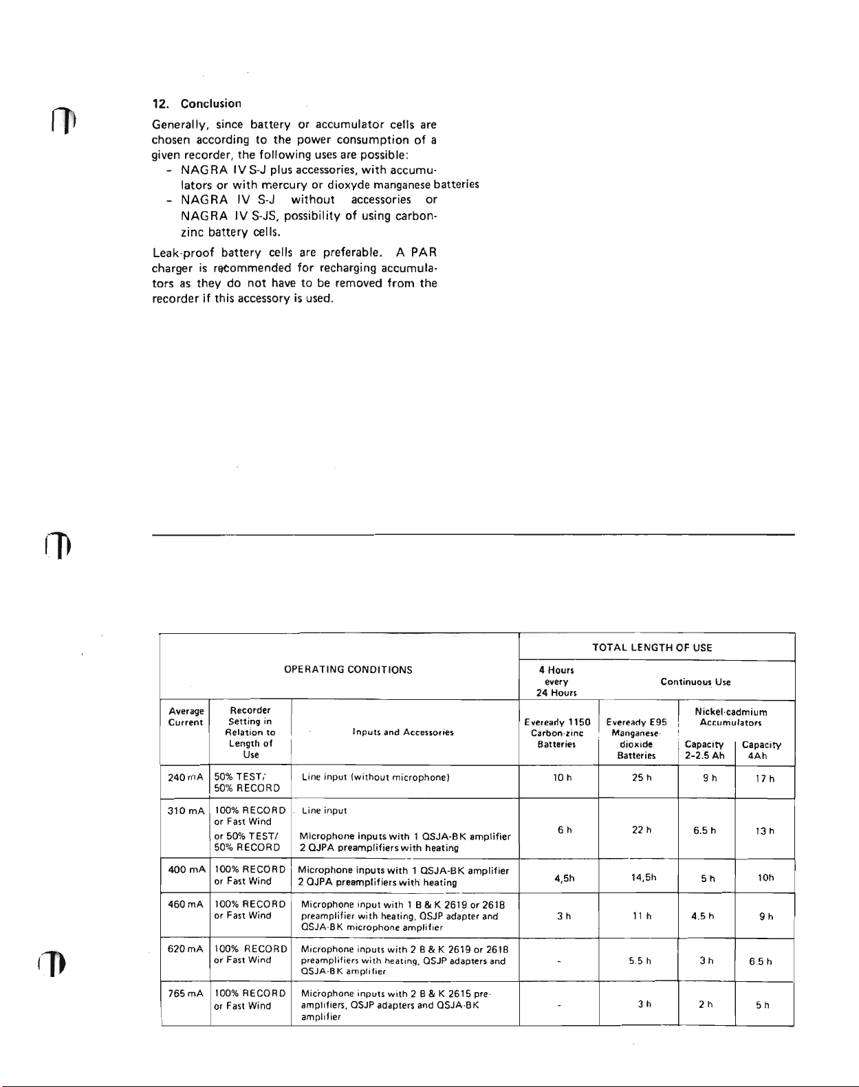
Average
Current
240mA
310mA
400mA
460mA 100% RECORD
620mA 100% RECORD
765mA
Recorder
Setting in
Relation to
Length of
Use
50% TEST; Line input (without microphone)
50% RECORD
100% RECORD line input
lor Fast Wind
or 50% TEST! Microphone inputs with 1 OSJA-B K amplifier
50% RECORD 2 QJPA preamplifiers with heating
100% RECORD
or Fast Wind
or Fast Wind
or Fast Wind
100% RECORD
or Fast Wind
TOTAL LENGTH OF
OPERATING CONDITIONS
Inputs and Accessories
4 Hours
every
24 Hours
Eveready 1150IEveready E95 Accumulators
Carbon· zinc : Manganese·
Batteries dioxide Capacity
10 h 25 h
6h 22 h
-
Microphone inputs with 1 QSJA-BK amplifier
2 QJPA preamplifiers with heating
Microphone input with 1 B & K 2619 or 2618
preamplifier with heating, QSJP adapter and 3h 11 h
QSJA·BK microphone amplifier
Microphone inputs with 2 B & K 26 19 or 261 B
preamplifiers with heatinq, QSJP adapters and
QSJA·BK amplifier
Microphone inputs with 2 B&K 2615 preamplifiers, QSJP adapters and OSJA·BK
amplifier
4.5h 5h
-
-
use
Continuous Use
Nickel·cadmium
I
I
Batteries 2-2.5 Ah
9h
6.5 h
14,5h
4.5 h
5.5 h
3h
3h
2h
Capacity
4Ah
17 h
13 h
10h
9h
6.5 h
5h
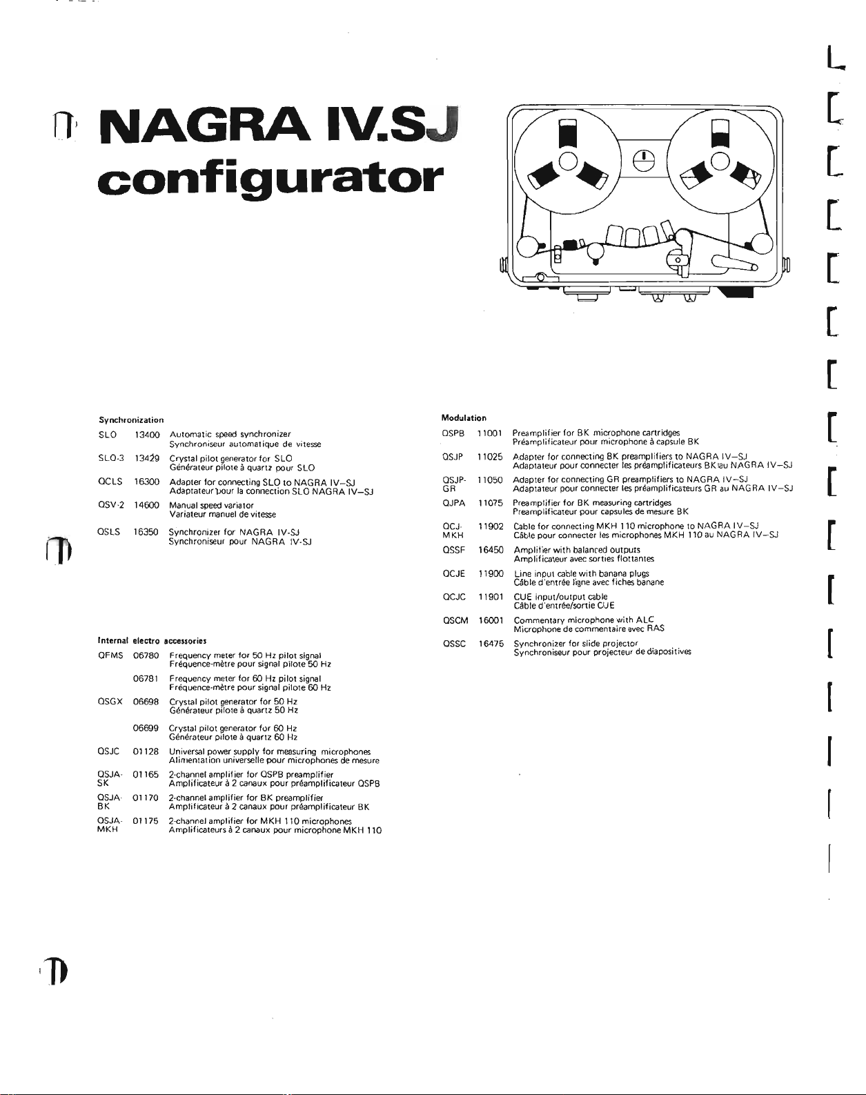
NAGRAIY.SJ
configurator
L
[
[
[
[
[
[
Synchronization
SlO 13400
SlO-3
GClS 16300
OSV-2
OSlS 16350
Automatic speed synchronizer
Synchroniseur automatique de vitesse
13419
Crystal pilot generator for SlO
Generateur piloteaquartz pour SlO
Adapter for connecting SlO to NAGRA IV-SJ
Adaotateur
14600
Manual speedvariator
Variateur manuel de vitesse
Synchronizer for NAG RA IV-SJ
Synchroniseur pour NAGRA IV-SJ
pour
la connection SlO NAGRA IV-SJ
f
Internal electro accessories
OFMS 06780 Frequency meter for 50 Hz pilot signal
QSGX
QSJC 01128 Universal power supply for measuring microphones
QSJASK Amplificateura2 canaux pour prearnpliticateur QSPB
OSJA
BK Amplificateura2 canaux pour preamplificateur BK
OSJAMKH
Frequence-rnetre pour signal pilote 50 Hz
Frequency meter for 60 Hz pilot signal
06781
Frequence-rnetre pour signal pitote 60 Hz
06698 Crystal pilot generator for 50 Hz
Generateur piloteaquartz 50 Hz
Crystal pilot generator for 60 Hz
06699
Generateur oitoteaquartz 60 Hz
Alimentation universelle pour microphones de mesure
2-channel amplifier for QSPB preamplifier
01165
2-channel amplifier for BK preamplifier
01170
01175 2-channel amplifier for MKH 110 microphones
Amplificateurs il2 canaux pour microphone MKH 110
Modulation
OSPB 11001
QSJP 11025
QSJP- 11050
GR
QJPA
11075
QCJ-
11902
MKH
16450
QSSF
OCJE 11900
QCJC
11901
16001
QSCM
16475
OSSC
Preamplifier for BK microphone cartridges
Preamplificateur pour microphoneacapsule BK
Adapter for connecting BK preamplifiers to NAGRA IV-SJ
Adaptateur pour connecter les preamptlficateurs Bk
Adapter for connecting GR preamplifiers to NAGRA IV-SJ
Adaotateur pour connecter les prearnplificateurs GR au NAGRA IV-SJ
Preamplifier for BK measuring cartridges
Preamplificateur pour capsulesde mesure BK
Cable for connecting MKH 110 microphone to NAGRA IV-SJ
Cable pour connecter les microphones MKH 110 au NAGRA IV-SJ
Amplifier with balanced outputs
Amplificateur avec sorties tlottantes
Line input cable with banana plugs
Cable d'entres ligne avec fiches banane
CUE input/output cable
Cable d'entree/sortie CUE
Commentary microphone with AlC
Microphone de commentaire avec RAS
Synchronizer for slide projector
Synchroniseur pour projecteur de diapositives
iau
NAGRA IV-SJ
[
[
[
[
[
(
I

NAGRAI\l..SJ
configurator
[
[
Power supply
ATN-2
OCAS 98001
OCAW
PAR
PPO
PO
PA-R 98251
PA-4 98254
AST
Carrying eases
OHP 14120
OHC 14125
OHTP 99009 Standard carrying casewith pocket
OHTRC 99220 Leather cover for OSET
Mains power supply 110-250 V with pilot signal output
14350
Alimentation secteur 110-250 V avecsortie signal pilote
Mains cable with Swissplug
Cable d'alimentation secteur avec fiche suisse
98003 Mains cable without mains plug
Cable d'alimentation secteur sansfiche secteur
13200
Charger for PA type rechargeable cells
Chargeur pour accumulateurs du type PA
14150 Multiple connection box
Bolte de derivation
98202 Set of 12 standard cells
Jeu de 12 piles standard
Set of 15 rechargeablecells withextension 2,5 Ah
Jeu de 15 accumulateurs avec rallonge 2,5 Ah
Set of 12
Jeu de 12 accumulateurs 4 Ah
Stabilized power supply for measurements
90400
Alimentation stabilisee de laborataire
Carrying handle
Poignee
Spare carrying strap for NAGRA IV-SJ
Courraie de rechange pour porter Ie NAGRA IV-SJ
Saooche standard avec poche
Cauvercle de sacachepour OSET
4 Ah rechargeable cells
E)(ternal electro accessories
OGB 14001 10 1/2" reel adapter
OCA
OGBC 14005
OGBN 14006
OGBA 14007 AEG-type hub holder
OSM 14700
IACC 17910
OCAS 98001 Mains cable with Swiss-type plug
OCAW 98003 Mains cable without mains plug
Mechanical accessories
OTIM 14650 Tape driven timer
OLEN
OAAC 06260 Tape cleaning blade
MAG
OSH
Adaotateur grande bobine 267 mm
Start-stop cable for remote controt
14102
Cable start-stop pour commandeadistance
Normal 8 mm cinespool holder
Parte-bobine cinema (standard I
NAB-type hub holder
Porte noyau type NAB
Porte noyau type AEG
Field monitor and amplifier
Maniteur-amplificateur de reportage
Removable cell compartment for OSM and IS
Magasin arnovible d'accumulateurs pour OSM et IS
Cable d'alimentatian secteur avec fiche suisse
Cable d'alimentatian secteur sansfiche secteur
Compteur temps eruralne par la bande
14655 Tape driven metrical counter
Compteur rnetrique entralne par la bande
A.deur de bande
9OBOI
90802 Electronically-controlled degausser 110 - 117 V
14130 Lid when using 7" reels
,
Electranically-contralled degausser220 - 240 V
Demagnetiseur Acommande electronique 220 - 240 V
Demagnetiseuracommande electronique 110 - 117 V
Couvercle pour I'emploi de babines 178 mm
[
[
[
I
I
I
 Loading...