

Page 1
OPERATING INSTRUCTIONS
AND
REFERENCE MANUAL
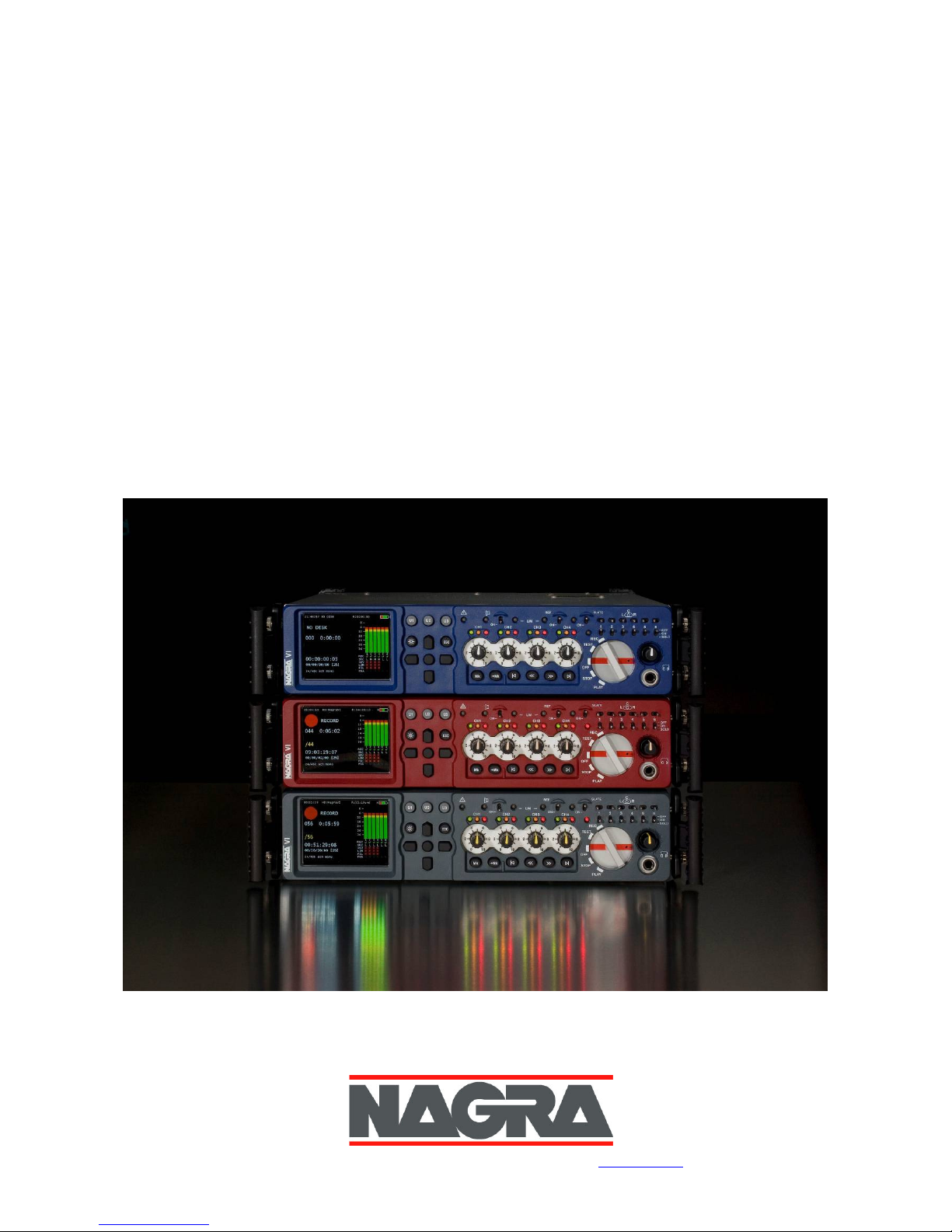
NAGRA-VI
NAGRAVISION SA, Kudelski Group, Rte. de Genè ve 22, 1033 Cheseaux, Switzerland. Tel :+41 21 732 0101 W eb : www.nagraaudio.com e-mail: audio_pro@n agra.com
Page 2

GUARANTEE / WARRANTY
NAGRA/KUDELSKI certifies that this instrument was thoroughly inspected and tested prior to leaving our
factory and is in accordance with the data given in the accompanying test sheet.
We guarantee the Nagra VI products of our own manufacture against any defect arising from faulty
manufacture for a period of TWO years from the date of delivery.
This guarantee covers the repair of confirmed defects or, if necessary, the replacement of the faulty parts,
excluding all other indemnities.
All freight costs, as well as customs duty and other possible charges, are at the customer's expense.
Our guarantee remains valid in the event of emergency repairs or modification being made by the user.
However we reserve the right to invoice the customer for any damage caused by an unqualified person or a
false manoeuvre by the operator.
We decline any responsibility for any and all damages resulting, directly or indirectly, from the use of our
products.
Other products sold by NAGRAVISION / KUDELSKI S.A. are covered by the guarantee clauses of their
respective manufacturers. We decline any responsibility for damages resulting from the use of these products.
We reserve the right to modify the product, and / or the specifications without notice.
Page 3

ABOUT THIS MANUAL
This instruction manual is broken down into several chapters. Each chapter covers different aspects of the
Nagra VI recorder, the settings, actual use, eventual problem localisation and technical specifications.
The operation section is divided into five different parts, the contents of each is listed below.
GUARANTEE / WARRANTY
ABOUT THIS MANUAL
INTRODUCTION TO THE NAGRA VI
Chapter I
Battery packs, charging and external DC power
Chapter II
keys, switches, connectors and more
Chapter III
Part 1
Part 2
Filters, Internal Mixer, Reference Generator,
M/S decoders, Outputs AES In / Out, Monitoring Page 22
Part 3
Working drive, Directory functions, Index / take
iXML METADATA, False start, Wild track, Pick-up
COPY functions, Autocopy and copy manager Page 32
Part 4
clock ref., sampling freq., File type, File name / size,
Screen settings, Beep, Speaker, Auto skip,
Start stop polarity User keys, Meter programming. Page 49
Part 5
(RTC), Auto folders, Name, Keyboard Selection,
Software Updates and Default settings, TEMPLATES Page 57
Chapter IV
Chapter V
Chapter VI
ANNEX I - Recording times Page 74
ANNEX II - iXML implementation Page 75
ANNEX III - The entire menu tree Page 76
ANNEX IV - Report example Page 84
ANNEX V - Template model Page 85
ANNEX VI - USB keyboard template Page 89
ANNEX VII - Conformity certificate CE Page 90
INDEX - Alphabetical index Page 91
Note: In addition to the alphabetical index at the end of this manual, the “footer” on the lower left
corner of each page indicates the section of the machine covered by the particular page.
This helps the reader navigate through the important areas.
The “POWER”
The “EXTERIOR”
The “INTERIOR”
The “MENUS”
The “AUDIO”
The “MEDIA”
The “SET-UP”
The “TOOLS”
TIME CODE
SOLUTIONS
SPECIFICATIONS
You need power first Page 5
Panels Left (input), Front, Right (output) and Back Page 9
– OPERATION
Menu tree structure and menu navigation Page 20
Settings > AUDIO, Inputs and input matrix, Limiters
DRIVES, FOLDERS, FILES, DIRECTORY
SETTINGS > pots assignment, Pre-record,
Media speed test, Re-formatting, Date / Time
Time code system, Internal Chase synchronizer Page 64
Error messages and problem solving Page 71
Full technical specifications Page 73
Page 4

Introduction to the Nagra VI
The Nagra-VI is a 24-bit solid-state 8-track digital audio recorder / player with built-in mixing functions
designed for classical music and film / TV location recording. It uses a 120GB internal hard drive (HDD) as
its principal storage medium and a removable Compact Flash card (CF) as a secondary media and file
transportation format. It is designed and built as an “on-location” recorder with the traditional Nagra
ruggedness. The audio information is stored as a digital linear Broadcast Wave file, and the recorded files
are iXML compatible. Equipped as standard with SMPTE/EBU time code generator and synchronizer, audio
limiters and filters (integrated into the microphone pre-amplifiers), high-speed USB-2.0 interface, a sunlight
readable 3 ½” TFT colour display and a detachable lithium-ion battery pack.
The front panel, chassis and features were all designed using the experience of previous NAGRA recorders
which render the Nagra-VI to very user-friendly and comfortable to operate even in harsh environmental
conditions. It is powered by a Lithium-Ion rechargeable pack (4.6 or 13.8 Ah). The record autonomy with the
standard 4.6 Ah pack is approximately 4 hours. With the optional high capacity pack this is increased to
more than 12 hours. It is equipped with two Hirose connectors allowing external RF receivers or digital
microphones to be powered from the battery box of the machine while on location.
The Nagra VI has six analogue inputs on XLR connectors, four of which are equipped with extremely high
quality microphone pre-amplifiers. They include, as one expects, +48V phantom powering and in-house
wound NAGRA transformers offering an improvement of +6dB in the noise floor when set to the 2.8mV/Pa
(for dynamic microphones) position. The other two connectors double up as AES A and B inputs for
connection to digital signal sources.
A system of user-friendly software menus are used for general machine configuation and for all internal
selections such as input sources, time code settings and the metadata entry or editing. Software updates
will be made available, from time to time, on our web site www.nagraaudio.com offerring additional features.
Explanations concerning the procedure for updating the software and the new features is covered under
“SOFTWARE UPDATES” in this manual.
Any questions you may have concerning the Nagra VI can be sent to us through the “Contact us” form on
the professional side of our web site www.nagraaudio.com
KUDELSKI GROUP
NAGRAVISION
Route de Genève, 22
CH-1033 CHESEAUX
SWITZERLAND
Tel : +41 21 732 0101
Fax : +41 21 732 0212
audio@nagra.com
www.nagraaudio.com
We would like to offer our special thanks to Peter Weibel, Los Angeles, USA for his assistance in the realization of this manual, and his
various inputs into the software ergonomics.
We’ve made it user
We’ve made it user----friendly!
We’ve made it userWe’ve made it user
friendly!
friendly!friendly!
Page 5
CHAPTER I THE P O W E R
YOU NEED POWER FIRST
Introduction
The Nagra-VI can be powered from one of the detachable Lithium-Ion battery packs or external DC through
the 4 pole XLR connector on the left side. It can also supply power to external equipment, such as RF
microphone receivers or a digital microphone, through the two Hirose connectors, each of which can supply
up to 500 mA at 12V.
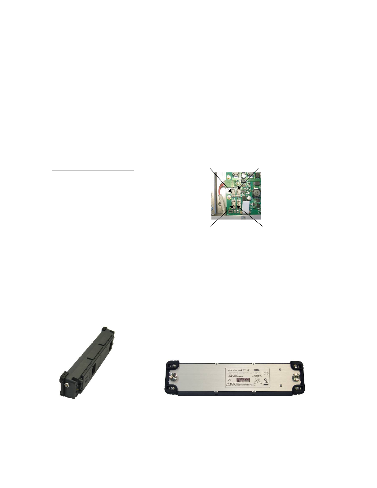
Fuses
The power supply board is accessible in the bottom of the recorder by removing the lower panel and is
equipped with 4 fuses to protect various elements. These fuses are of the OMF 63 type and manufactured
by Schulter and do not require soldering. A pack of 4 fuses (2 of each) is included with each new recorder
and additional replacement fuses are available through your Nagra agent
Fuse Value Protects
F1: 5A 4 pole XLR DC input connector
F2: 5A Detachable battery pack
F3: 500mA Hirose connector
F4: 500mA Hirose connector
Replacement fuse part numbers:
F1 & F2 # 54 82001 500
F3 & F4 # 54 82000 500
F4 F3
F2 F1
.
Detachable battery packs
The Nagra VI is delivered with a 4.6 Ah Lithium-Ion battery pack NVI-BB1 (KSA# 70 32110 000) weighing
800g (1.75 lb), it will power the recorder for approximately 4 hours of continuous operation. This pack will
take about 3 hours to be fully charged, and it is strongly recommended to fully charge the battery before
using the recorder for the first time.
As an option a heavier 13.8 Ah high capacity Lithium-Ion battery pack NVI-BB2 (KSA# 70 32115 000)
weighing 1.3 kg (2.8 lbs) is available as an option and this will power the recorder for up to 12 hours of
continuous operation. This pack will take around 5 hours to be fully recharged.
Both battery packs have identical external physical dimensions. However
the larger capacity pack with more internal Lithium-Ion blocks is heavier
and has a different identification label.
Chapter I
(Power, batteries and charging…)
July 2010 5
Page 6

Mains power unit
The NVI-PSU (KSA# 20 32250 000) external mains power unit supplied with the Nagra VI is a 100 - 240V
50/60Hz supply rated at 5A. It is fitted with a three pole LEMO connector and should only be connected to
the Nagra VI battery packs. As soon as the power supply is connected to the mains, the green LED on the
top of the supply will light.
The Nagra VI can be operated while the mains power is connected to the battery box on the rear of the
machine without danger, and it will supply enough energy to power the recorder and recharge the attached
pack at the same time.
Charging of the battery packs
The detachable battery boxes are fitted with two LEDs on the rear side. The green LED will light when the
external power supply is present, and the yellow LED will light to indicate that the internal Lithium-Ion battery
pack is being charged. No harm will be caused to the lithium packs if the external charger is left connected
as they cannot be “Overcharged”.
The detachable battery packs WILL ONLY BE CHARGED if the external mains power supply (supplied with
the recorder) is connected directly to the battery box (The battery pack can be attached to the recorder or
not).
The battery pack WILL NOT BE CHARGED from an external DC source connected to the 4 pole XLR
connector on the left side panel of the recorder.
Charging times
NVI-BB1 4.6 Ah pack is approximately 3 hours
NVI-BB2 13.8 Ah pack is approximately 5 hours
Power indication
The top right corner of the main display shows a “fuel gauge” type charge indication of a battery at all times.
The right portion (green in the picture) corresponds approximately to the remaining operating time for the
machine. This means with the 4.6Ah battery pack a half-full battery indication represents about 2 hours
running time remaining, and three times more with the larger 13.8Ah pack.
The RED section should be considered as “reserve” and represents “Low Battery”. This portion corresponds
to about 10-15 minutes on the standard pack and 25-30 minutes on the larger one.
When the yellow zig-zag “flash” is present, this indicates that external DC power is present on the 4 pole DC
connector and the coloured fuel gauge battery will now indicate the external voltage supplied to the XLR
connector rather than remaining time. This means that with 16V applied the battery symbol will be “full” and
with 9V applied then it shows empty. This feature allows the user to monitor the condition of external
batteries (in voltage terms).
- Half-full battery
- Battery full
- External DC connected to the 4-pole XLR connector
- External Mains power connected to the battery box (Lithium-Ion is charging)
Note: All times and durations indicated in this section assume that the phantom powering is OFF and that
no external equipment is connected to the Hirose connectors. In addition it is assumed that the
battery packs are in good condition and are fully charged where necessary.
Chapter I
(Power, batteries and charging…)
July 2010 6
Page 7

Time Code and Real Time Clock (RTC) powering.
A “super capacitor” will keep the time code and real time clock running for about 3 minutes if the battery box
is removed from the machine and no external DC is present on the 4 pole XLR connector. This ensures that
the time code will remain accurate while the battery pack is replaced. If the date and time is lost, then it will
automatically be requested when the next power on is made.
External DC powering
The Nagra VI may be powered through the 4-pole XLR connector on the left side of the chassis with a DC
supply ranging from 9 to 16V and is designed to power the recorder from car batteries and so on. As soon
as an external DC supply is connected the recorder will switch seamlessly to this supply and the battery
pack on the rear will no longer be consumed. It may even be removed entirely from the recorder if
necessary.
With external DC power present on the 4 pole DC connector, the battery indicator on the main display will
show the yellow “flash” across it to indicate that sufficient external DC is available and the red “Low battery”
portion is eliminated. This means that with 16V supplied the battery symbol will be “full” and with only 9V
applied the indicator would be at the left end.
- No external DC present with a full battery pack attached
- External DC connected with about 13V applied
Note: The external DC supply can be connected and disconnected at any time without any interference to
the machine even during recording as long as a charged battery pack is fitted to the rear of the
recorder.
Chapter I
(Power, batteries and charging…)
July 2010 7
Page 8

Lithium-Ion battery life and care
Lithium-Ion battery packs will last for between 500 and 1’000 charge cycles before being replaced, which if
correctly cared for, in the case of a Nagra VI would represents about 5 years or so. However there are some
important points to be made concerning the “housekeeping” of such packs.
Contrary to NiCd packs, the most damaging event that can happen to a Lithium pack is for it to discharge
completely. If this happens it is very likely that the pack will be irreparably damaged. In the Nagra VI the
software will close the machine down well before the battery pack gets to a critical charge point thus
protecting the cells. In addition, a security circuit inside the pack itself will also cut-in should the pack get too
drained, however in any event running the battery flat is strongly inadvisable.
It should be remembered that even with the recorder turned OFF, the Time Code circuit WILL CONTINUE
TO DRAW POWER from the pack. The time code circuit will completely drain a fully charged 4.6 Ah battery
pack in about 1 month, and a 13.8 Ah pack in about 3 months.
A Lithium-Ion pack will have a longer lifetime if it is regularly recharged (even when half full) and it is not
possible to “overcharge” the pack. Unlike a NiCd battery, the “memory” effect does not exist with Lithium-Ion
packs.
A charged Nagra VI battery pack, in good condition, can be stored, disconnected from the recorder, for a
period of 1 year without risk. If one wishes to store a Lithium pack for an extended period at room
temperature (a year or more) then ideally it should be charged to about 50% before storage (suggested by
the manufacturer). In such a case, after 1 year the pack will have lost about 4% of its total capacity, whereas
if the pack is charged to 100% before storage, after 1 year it will have lost nearly 20% of its total capacity.
(At lower storage temperatures, this effect is minimized). One should always verify from time to time that the
pack remains at around 50% and recharge a little as necessary.
So remember:
- DO NOT store the Nagra VI for long periods with the battery box attached.
- NEVER allow the pack to be drained completely.
- ALWAYS keep the battery charged as no harm will occur.
Chapter I
(Power, batteries and charging…)
July 2010 8
Page 9
CHAPTER II THE EXTERIOR
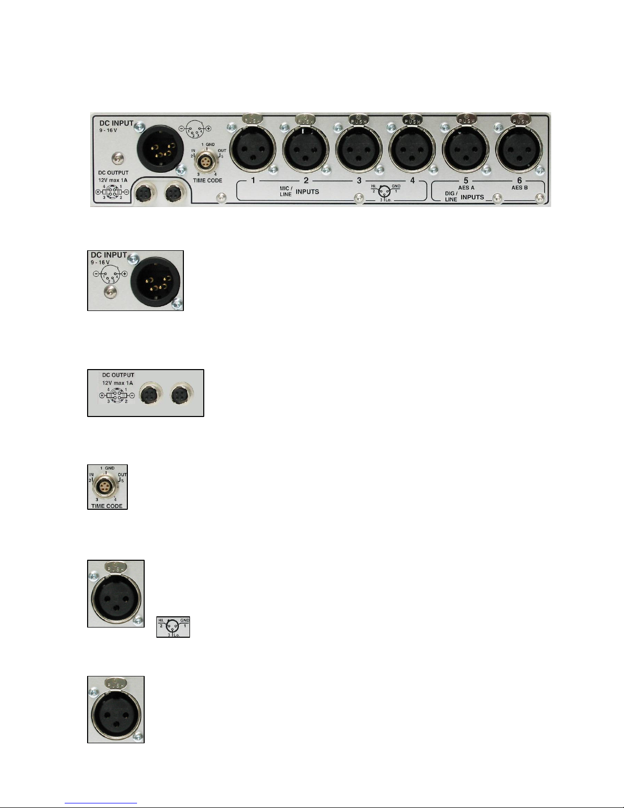
LEFT SIDE “Input” PANEL
External DC Input Connector
A standard 4-pole XLR connector: Pin 1 is ground, pin 4 is the +ve pole
(pins 2 and 3 are not connected). The input voltage range is from 9-16 Vdc
(max) and the recorder requires a minimum 3.3 A.
This connector delivers power to the machine, as well as to the 2 Hirose
outputs, and will NOT charge any attached Lithium-Ion battery pack.
DC Output Connectors
Two Hirose connectors: 12 Vdc output, maximum current drain for each
connector is 500 mA. These connectors are suitable for supplying power to
RF receivers or external digital microphones, or even external USB drives.
Time Code Lemo Connector
The time code input and output is located on a traditional 5-pole LEMO
connector, the pinning of which corresponds to that of the IV-STC, the
NAGRA-D and T-Audio-TC as indicated.
(QCTCU cable # 70 16909 000 – LEMO to “open-ended” TC cable)
Input Connectors 1 to 4 (Mic / Line)
These inputs can be used for dynamic or condenser mics or as analogue
line inputs. The sensitivity for the different microphone input sources is
selectable from 2.8 mV/pa to 30 mV/pa (10 mV/pa on version 1 audio
cards) in the audio settings menu. When used for line inputs, they will
accept up to +24 dB.
Input Connectors 5 and 6 (Line / Digital)
The input connectors 5 and 6 (Line / Digital) can be used as the two
additional analogue line inputs or as the digital AES “A” & “B” inputs. This
selection, as well as the analogue line input level pre-set, is made in the
menus. The AES inputs are standard AES 31 stereo audio inputs.
Chapter II
(Exterior of the recorder – Left side)
July 2010 9
Page 10

The FRONT “Operational” PANEL
MAIN DISPLAY SCREEN
The main screen of the Nagra VI is a 3½” TFT display and is used to show the status as well as levels and
menus of the recorder. It was specially chosen for extremely wide “sunlight readable” viewing angle as well
as its performance over a wide temperature range.
1. Internal Real Time Clock set in the Date & Time menu.
2. Selected working drive (HD / CF / USB) followed by selected working folder name.
3. Remaining time for the selected drive in HH:MM:SS according to the current file type selection.
4. Battery status. The example shows a fully charged pack.
5. Previous peak position for the modulometer.
6. Modulometer 8 tracks. The display is darker when not armed for recording (e.g. 3 + 4 here).
7. Track numbers.
8. Indicates the tracks that are active “armed” and will be recorded. In this example: tracks 1,2, and 5 - 8.
9. Indicates the input source. In this example: 1 & 2 are Mikes, 3, 4, 5 & 6 are Line, 7 & 8 have no input but
the modulometer is active meaning that a down-mix is being made to tracks 7 + 8.
10. Indicates + 48V phantom power. In this example: 1 & 2 only have +48V.
11. Indicates audio limiter. In this example: No limiters are activated.
12. Indicates vortex filter. In this example: No filters active.
13. Phase indication. “N” (grey) indicates normal and “I” (yellow) for inverted phase of the channels.
14. File type to be recorded. In this example, the files are 24 bits 48 kHz, 6 channel recording in polyphonic
format, and the auto copy feature is activated.
15. Time code user bits and current frame rate selection.
16. Time code time information.
17. Metadata Scene and take number. In the example the wild track has been chosen ( -W)
18. Metadata project name.
19. Actual index number and timer position.
20. Function icon and status.
21. “H” / “C” / “U” indicator of hard disk, CF or USB drive access.
Chapter II
(Front panel)
July 2010 10
Page 11
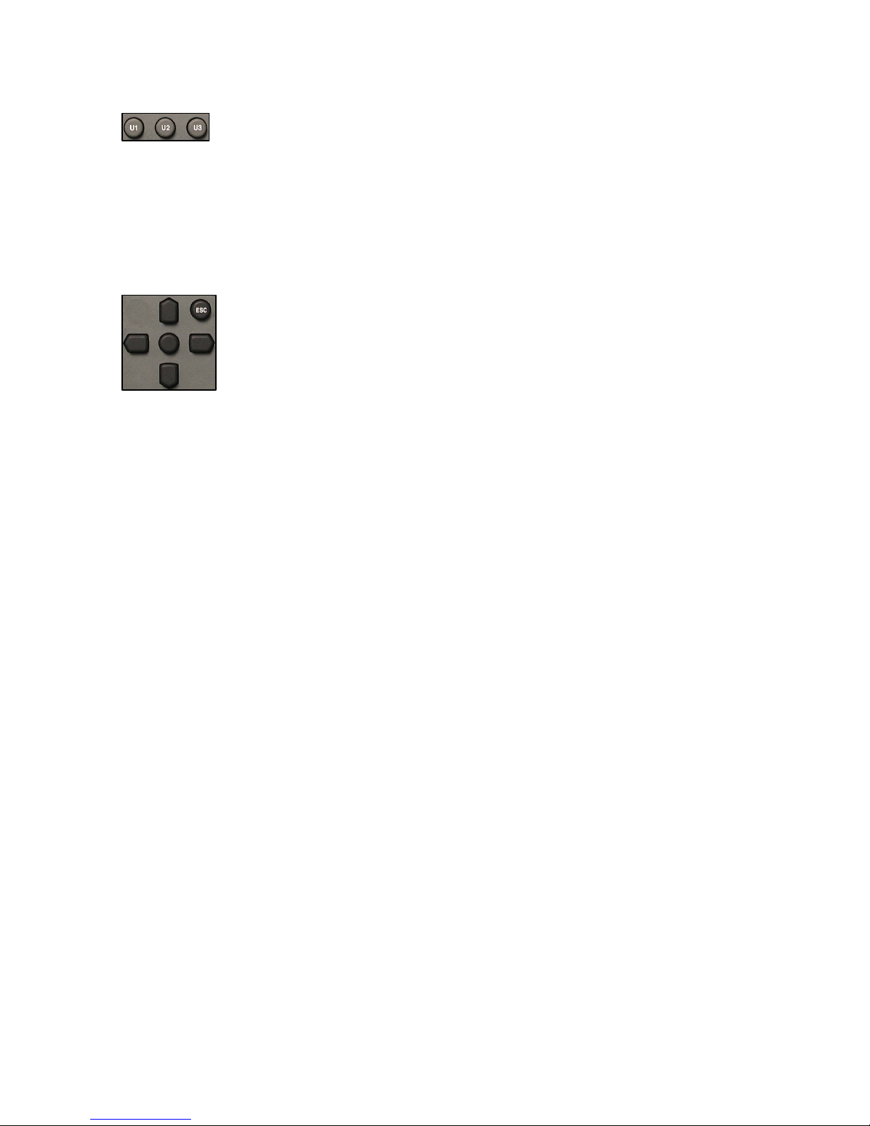
User Programmable Keys
The keys U1, U2, U3, are “short-cut” keys and are USER pre-programmed via the
menus, they give rapid access or short-cut to different menu positions.
Programming of the keys is covered in the menus section of this manual under the
User keys programming screen in the “Settings” section of chapter III part 4. The
chosen programming for these keys is stored in the internal machine templates, if
they are being used. Thus, each template can have three different sets of functions
on the user keys if desired. These user keys are duplicated on an external USB
keyboard on the function keys F1, F2 and F3.
Menu Navigation keys
Access, navigation and excecution of the menus.
Pressing the center key accesses the main menu and serves as the “Select” key.
The Up/Down and Left/Right keys navigate through all the sub-menus and settings.
The ESC key moves one step backwards through the menu tree. If ESC is held,
the cursor will jump completely out of the menu mode. These keys are duplicated
on the arrow keys of an external USB keyboard when connected.
Additional functions depending on the current operating mode (or menu position):
Screen / Mode Key(s) Function
Default / Main Up Indicates the highest audio level on the bar graph display,
since the last time its memory was reset
Up+Down Reset the highest audio level memory.
Right Display the Modulometers screen while the key is pressed.
Left Display the default “status” screen while the key is pressed.
Left + Right Temporarily return all pots to their analogue input and
headphones for the monitoring pot.
Mixer Up Increase the fader position.
Down Decrease the fader position.
Up+Down Toggle from Maximum to Minimum fader positions.
Left Pan to the left
Right Pan to the right
Left + Right Toggle between full left, centre and full right for the pan pot.
Mixer out Left + Right Jump to 0dB position
Up+Down Toggle from OFF to +12dB output gain.
Character / data entry Up Step to the next character in the alphabet.
Down Step back one character in the alphabet.
Up+Down Delete a character (metadata, directories, naming…).
Right Move one position to the right.
Left Move one position to the left.
Right+Left Insert a blank space character (metadata, directories, naming…).
Pot. Assign Offsets Up Increase the pot offset by 0.1 dB per press.
Down Decrease the pot offset by 0.1 dB per press.
Up+Down Reset a selected pot offset to zero.
Chapter II
(Front panel)
July 2010 11
Page 12

Light key
When pressed, the display illumination and led brightness will
alter. The display will start to “dim” to its minimum position. If
pressed again it will start to increase to its maximum illumination.
The setting of this illumination intensity is stored in the internal
memory of the recorder, however this is not saved in the
templates.
Alarm / Warning Led
This is a warning indicator. Different errors are indicated by various
blinking combinations.
Rapid blinking: Clock unlock error (Clock reference menu)
Double blink: AES error (No AES present on inputs)
Loudspeaker switch
Used to switch ON or OFF the built-in monitoring loudspeaker on
the top panel. Depending on the menu settings, the speaker can
be automatically turned OFF when not in PLAYBACK. The signal
fed to the loudspeaker is selected using the monitoring selector
switches and the volume is adjusted with the headphone level
control.
REF, Reference Generator
This momentary snap-switch activates the internal reference tone
generator on all channels. The signal level, desired frequency and
operating mode can be pre-set in the reference generator menu.
This switch can be set to toggle ON/OFF upon each consecutive
press in the reference generator menu, allowing long reference
tones to be recorded without holding the switch down.
SLT, Slate mic (built-in)
This momentary snap-switch activates the internal “slate”
microphone located behind the main selector knob. The signal will
be fed to all channels.
Monitoring Matrix
This group of switches determines the matrixing of the audio
channels to the headphone outputs and built-in loudspeaker.
The top row of switches allows Left / Centre / Right for each
input, and the lower row selects On / Off or Solo (Mono centre) for
each input.
If all 6 switches are set to the upper OFF position two additional
monitoring possibilities are available “Mix if mon off” will monitor
the mix and “7-8 if mon off” will set the monitoring to channels 7
and 8. Both these selections are made in the monitoring menu.
These will also affect the audio outputs if this feature is selected in
the Line / AES out menu, in which case the audio outputs will
follow the monitoring matrix selections. If the mix has been
recorded on 7 & 8 then both positions will be the same
except during playback.
Momentary mono can be achieved by pressing the headphone
level pot.
Chapter II
(Front panel)
July 2010 12
Page 13
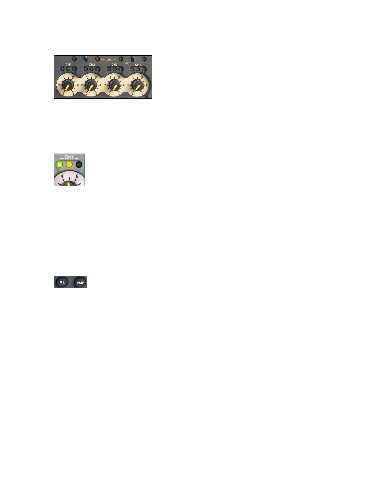
Potentiometer Panel
These four programmable potentiometers are used to finely trim
the input sensitivity of the four microphone inputs when in their
default mode.
In the Potentiometer Assignment menu, each of the four
potentiometers can be assigned to one or more microphone or
line inputs, one or more mixer gain controls or left unassigned (no
action, locked). The corresponding input level is automatically
memorized as soon as it no longer has a potentiometer assigned
to it.
The levels and assignments can all be saved in the templates.
The default setting for all four potentiometers is for the
microphone input sensitivity.
LED level indicators
The 3 led’s above each potentiometer indicate signal presence for
each microphone pre-amplifier. They indicate in parallel with the
bar graph displays of the main screen.
The first green led indicates a signal level above -40dB
The centre yellow led will light for a signal above -12 dB
The right (red) led will indicate a level above -1 dB. (These
illumination levels / points can be programmed in the meter
programming menu)
Limiter indications
The 4 yellow led’s above the level indication leds show the activity
of the audio input limiters. (Menu selectable individually or in pairs)
The limiters start to activate at a signal level of -8 dBFs and from
the range of -8 dB to -2 dB they compress the audio by 36dB (max
+ 36dB for -2dBFs).
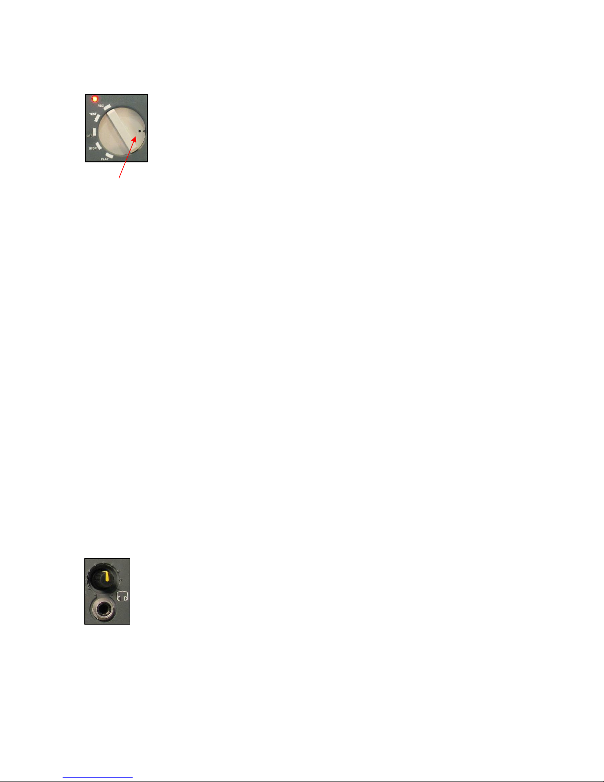
Marker Keys
During record and playback, the “Mk” key adds a marker
position to the recording. During playback, the “➨Mk” key will jump
to the marker position. These two features could be considered
as “Reset counter” and “Goto Zero” as used in analogue
recorders. This marker is not saved in the file headder and will be
reset when the machine is switched off.
Chapter II
(Front panel)
July 2010 13
Page 14

Forward, Rewind Skip Keys
These transport keys have the similar functions as a CD player.
The recorder will always return to its previous operating mode after
use, ie Playback, SYNC (Chase) or Stop.
From left to right:
I< Skip to the beginning of the current take. (Ctrl + F1 on external
USB keyboard)
Each consecutive press will jump back by 1 further take.
If held, the skip back command will auto repeat.
<< Reverse search at 4x nominal speed in playback (Ctrl + F2 on
external USB keyboard) and rapid rewind at 127x in STOP (Alt
+ F2 on external USB keyboard).
>> Forward search at 4x nominal speed in playback (Ctrl + F3 on
external USB keyboard) and fast forward at 127x in STOP (Alt +
F3 on an external USB keyboard.
>I Skip to the beginning of the next take.
If held, the skip forward command will auto repeat.
(Ctrl +F4 on external USB keyboard)
Additional functions:
>I Pressing this during record will increment the index number by 1.
Each press during record will start a new file (not a new take).
Pressing while in chase mode will momentarily skip forward then
return to chase mode.
I< Pressing this key while selecting REC with the main selector will
activate the “False Start” command in the metadata.
Pressing while in chase mode will momentarily skip back then
return to chase mode.
<< + >> If pressed while moving the main function selector to PLAY the
internal time code chase synchronizer will be activated according
to its programmed mode of operation. (Alt + F5 on external USB
keyboard).
Chapter II
(Front panel)
July 2010 14
Page 15
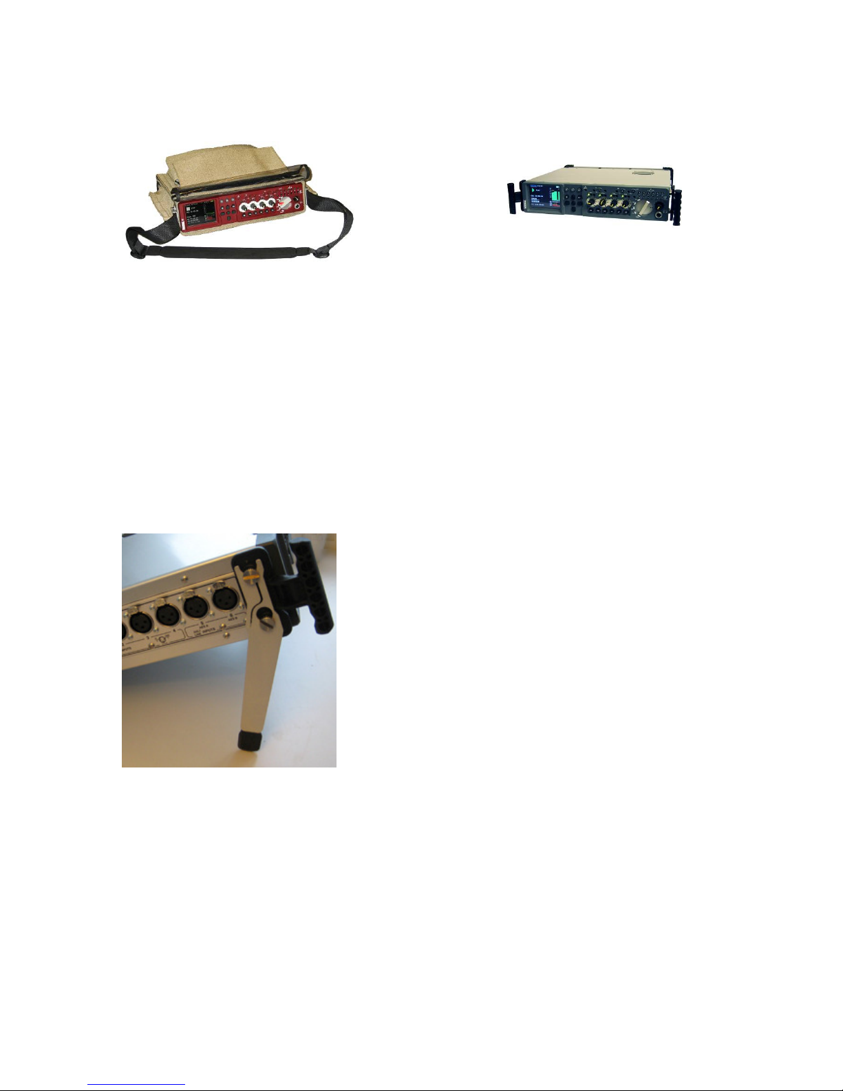
Main Function Selector
The rotary main function selector is the principle operating and ON / OFF switch for
the Nagra-VI. It is a five position rotary selector. Each position is explained below.
OFF: This is the main power OFF position of the Nagra VI. None of the circuits
of the machine are powered in this position except the real time clock and
the time code generator.
When OFF is selected the main display will show “POW OFF” while all the
machine settings are being saved. Moving the selector during this phase
Int / Slate Mic. will prevent the machine from stopping but will save all the internal settings
of the recorder.
Power OFF is completed 3 seconds after selection but will NOT occur
while the machine is copying files, only once the copy procedure is
completed.
TEST: In this position all the circuits are powered allowing recording level, audio
monitoring adjustments, menu verification and alteration. This can be
considered as a "stand-by before record" position. If the Pre-record
function (Ctrl + F11 on external USB keyboard) is active the REC led
flashes and some menu alterations are prohibited. In this position the time
code to be recorded will be fed to the time code lemo output.
REC: This is the standard position used for recording. When recording, the red
led beside the main function selector will be alight. Recording will only
occur on the pre-selected channels. Always remember to select or “arm”
the channels to be recorded. (Ctrl + F12 on external USB keyboard)
STOP: In this position the push-button transport keys are active for rewind, fast
forward and skip functions. Access to all menus and machine settings is
also enabled. (Ctrl + F6 or Ctrl + Space bar on external USB keyboard).
In this position the time code output will be frozen at the last value read.
In this position the audio inputs are not fed to the outputs.
PLAY: This is the PLAYBACK position. The Nagra VI will start playback from
either from its current position, or from the beginning of the last recorded
take if the machine had previously been in record mode. (Ctrl + F5 on
external USB keyboard).
In this mode the push-button transport keys for play and search (4x) are
active.
In this position the time code from the take being played will be fed to the
time code lemo output.
Headphone Jack & Level adjustment
The potentiometer adjusts the output level for both headphone outputs (front and
right side panel) as well as for the loudspeaker on the top panel.
Pressing and holding the potentiometer will make the selected audio signal(s)
available in mono on both channels.
In the POT ASSSIGNMENT menu it can be programmed to adjust the line output
level or the output level of the internal mixer if desired. Whenever a new attribution
is chosen for the potentiometer, the previous setting will be stored in the memory of
the recorder.
Pressing the Left and Right arrow keys simultaneously will temporarily
return the pot assignment to the headphone level control mode.
Chapter II
(Front panel)
July 2010 15
Page 16
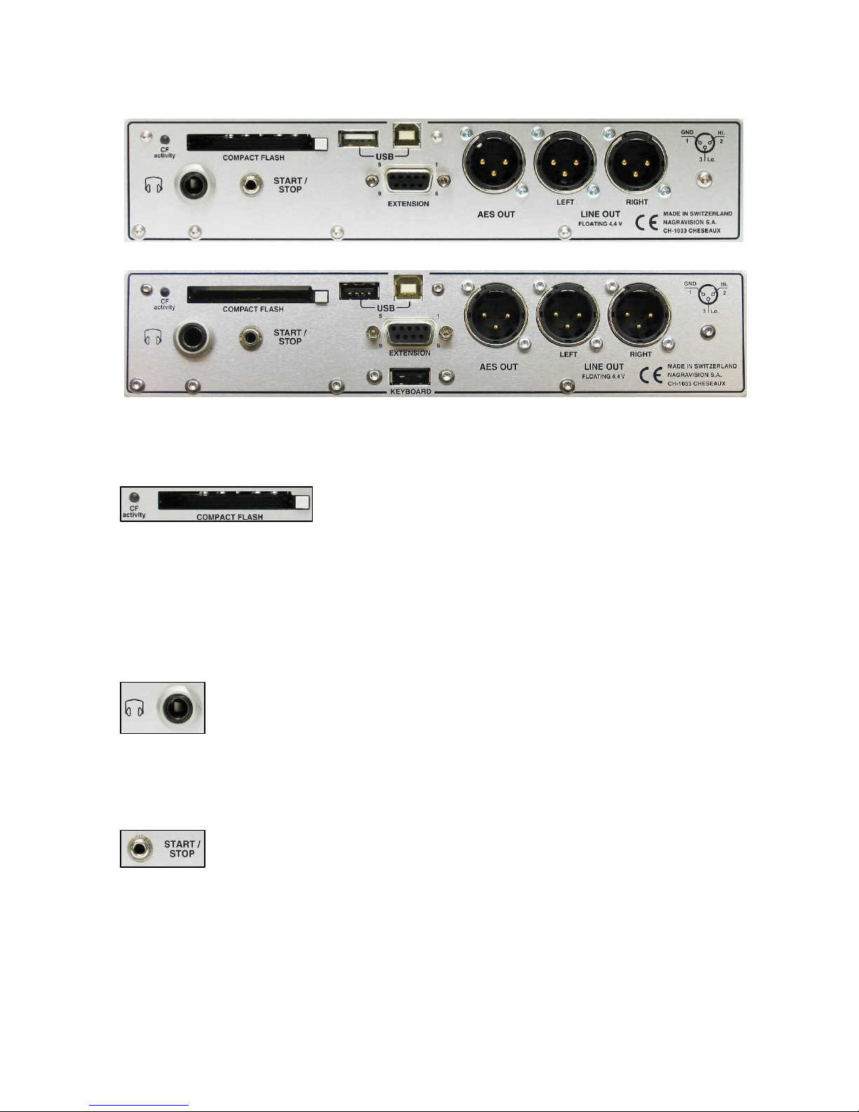
CARRYING CASE, STRAP and HANDLES
The red-fronted Nagra VI in the carrying case shows the shoulder strap attached, and a grey machine is
fitted with the supplied carrying handles.
The front sides of the recorder are fitted with 4 screw threads, into which either a shoulder strap or carrying
handles can be attached. The carrying handles also serve to protect the front panel of the Nagra VI and to
support if it is up-ended while changing the battery pack.
Supporting legs
The Nagra VI is supplied with two metal supports that can be easily attached to each of the handles without
removing the fastening screws. They lift the front of the recorder by about 10cm (4 inches) to make tabletop
operation more comfortable. Replacement feet can be ordered from your nearest NAGRA dealer using the
part number 01.32050.028
Chapter II
(Case, strap and handles)
July 2010 16
Page 17
RIGHT SIDE “Output” PANEL
(Standard panel)
(Panel showing the optional second USB host connector)
Compact Flash Slot
This slot permits the use of removable compact flash memory
cards type I & II. To remove the CF card, press the white button
once to unlock / release the button, then press it in fully and the
card will eject. If the CF activity led is alight continiously or
blinking, this indicates that the CF card is being accessed, so
removing it at that moment may result in errors. If the led is alight
and the main selector is set to OFF then the machine will only
switch off once it has completed the operation in progress (for
e an auto-copy instruction).
Headphone Jack
This is a standard ¼" (6.3 mm) stereo jack connector and is in
parallel with the jack on the front panel. The level of both
headphone outputs is adjusted using the headphone level control
on the front panel. The audio supplied to the two headphone
connectors depends on the menu settings and the monitoring
switches.
Start / Stop Mini Jack
This miniature 3.5mm jack is a remote start / stop connection or
“fader start”. It is a simple contact closure and activation is
achieved by making a short-circuit between the terminals. The
“polarity” can be selected in the menus, and if the position
“Inverted” is selected, then the function will be activated when the
connection is shorted out rather than “open”. The function depends
on the position of the main function switch. In the record position, it
will switch between record and test. If the pre-record function is
active then the start / stop will switch between record and Pre record. In playback it will switch between play and stop.
Chapter II
(Exterior of the recorder –Right side)
July 2010 17
Page 18
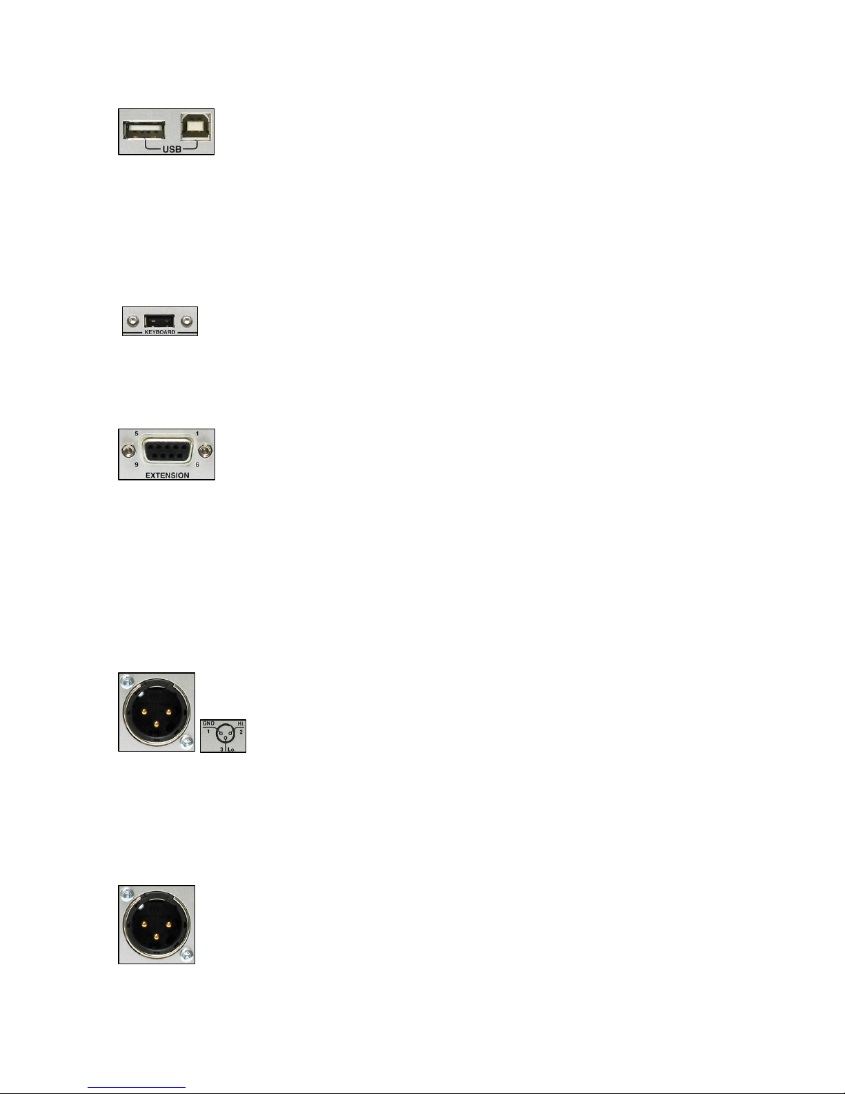
USB connectors Host / Device
These USB connectors are high speed USB 2.0 ports.
The HOST port (left connector in the picture) can be used to
connect an external USB keyboard, USB memory key, external
hard drive or even a DVD-RAM burner.
The device port (right side of the picture) connector links the Nagra
VI to a PC or MAC and will be recognized as two generic external
disk devices (the Hard drive and the CF card will both be shown),
allowing rapid file transfer from the internal HDD. An external USB
drive connected to the HOST port will not be seen by the computer
via the device port.
USB keyboard
This is an optional second USB host connector that allows a USB
keyboard to be connected to the Nagra VI while the main host
port (above) is being used by another USB device (USB key,
External Hard Drive….). Contact your Nagra agent to find out
about the installation of this option.
Extension Connector
This female miniature “D” type 9-pole connector has two AES
outputs (tracks 1-2, & 3-4), Word clock In/Out video reference.
Pin# Connnection
1 MIDI (low) (future)
2 AES 1 + 2 Out (low)
3 Ground
4 AES 3 + 4 Out (low)
5 External Word clock / sync IN
6 MIDI (high) (future)
7 AES 1 + 2 Out (high)
8 AES 3 + 4 Out (high)
9 Word clock OUT
AES Output connector
The 3-pole male XLR AES output connector is a digital output
corresponding to the format of the AES bus used throughout the
professional audio industry. The resolution is of 16 or 24 bits
depending of the current machine settings, and if the machine is in
24 bit mode this output can be redithered to 16 bits to feed a
lower resolution output. In the default mode, it will correspond to
the digital outputs of channels 1 and 2 although it can be set to
other channels in the menu mode in the AES out source menu.
This liason allows direct connection to any other digital equipment
fitted with an AES interface.
Line Output Connectors
These two 3-pole XLR connectors are the standard analogue
audio transformerless symmetrical floating outputs. The output
level on these connectors is adjustable from -6 to +15 dBu for
0dBFS on the meters. It can also be adjusted using the
headphones pot if assigned to do so. The audio signals fed to this
output is selectable in the Line out source menu.
Chapter II
(Exterior of the recorder –Right side)
July 2010 18
Page 19
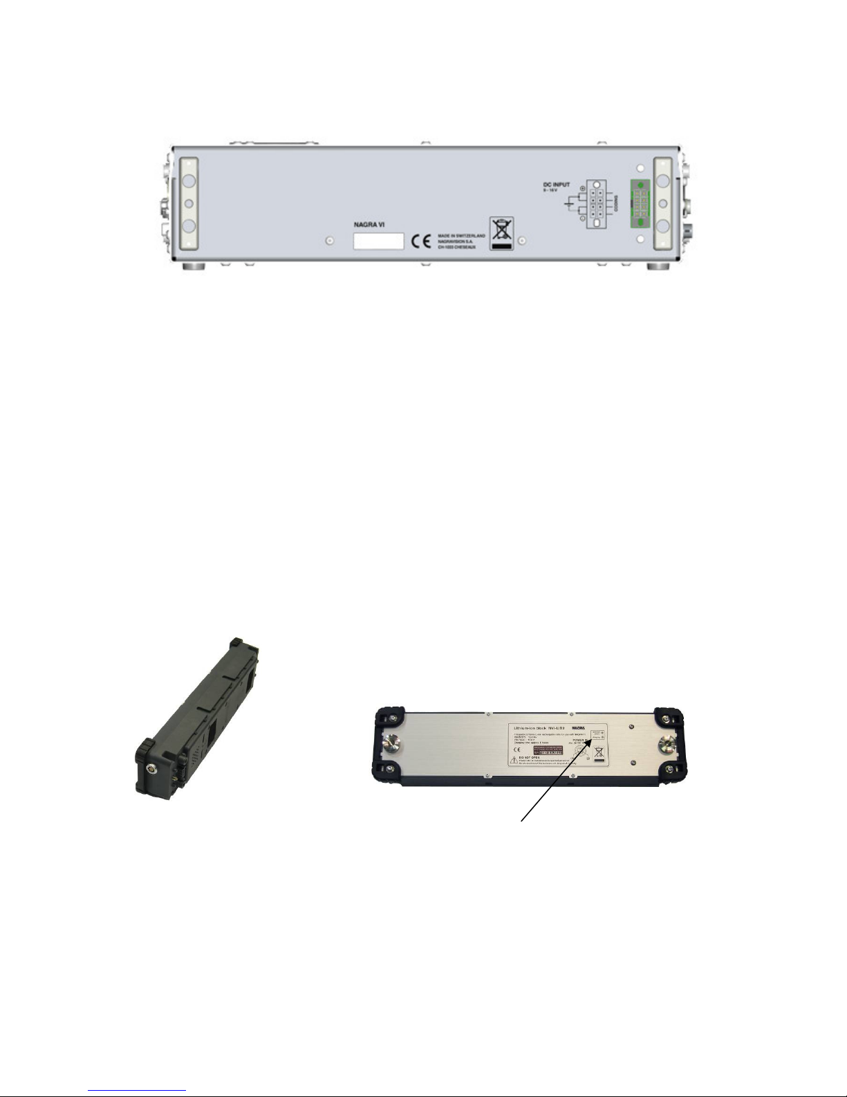
The BACK and BATTERIES
Rear view of the Nagra VI showing the two battery support brackets.
On the right side the eight pin connector where the external batteries are connected.
Serial number
The serial number is also burned into the internal memory of the recorder and cannot be altered or erased.
The serial number can be seen in the “Tools / software / about” menu screen and can also be found on the
sticker on the rear panel.
Battery packs
The Nagra VI comes with a 4.6 Ah Lithium-Ion battery pack NVI-BB1 (KSA# 70 32110 000) weighing 800g
(1.75 lb) that will power the recorder for approximately 4 hours of continuous operation. This pack will take
about 3 hours to be fully charged and it is strongly recommended to fully charge the battery before using the
recorder for the first time.
As an option a heavier 13.8 Ah Lithium-Ion battery pack weighing 1.3 kg (2.8 lbs) NVI-BB2 (KSA 70 32115
000) is available and will power the recorder for more than 12 hours of continuous operation. This pack will
take around 5 hours to be fully recharged.
Both battery packs have identical external physical dimensions.
However the larger capacity pack however with more lithium-ion blocks
is heavier and has a different identification label.
Power and charging indication leds.
Chapter II
(Exterior of the recorder - Rear side)
July 2010 19
Page 20
CHAPTER III (Part 1) The M E N U S
A POWERFUL SOFTWARE-BASED MENU STRUCTURE
General structure of the menus
The Nagra VI incorporates a system of menus similar to the "tree" of directories and sub-directories on the
hard disk of a computer. The functions that are available through the menus are, in principle, settings of the
Nagra VI rather than operations that need to be done frequently during normal use of the recorder. The
menu mode access is achieved using the centre key, and viewing and modification is made by using the
navigation keys located on the front panel. If an external USB keyboard is connected, then access to the
menu mode is achieved by pressing the “Return” key.
User-friendly menu software
Navigation through the menus is straightforward and couldn’t be easier.
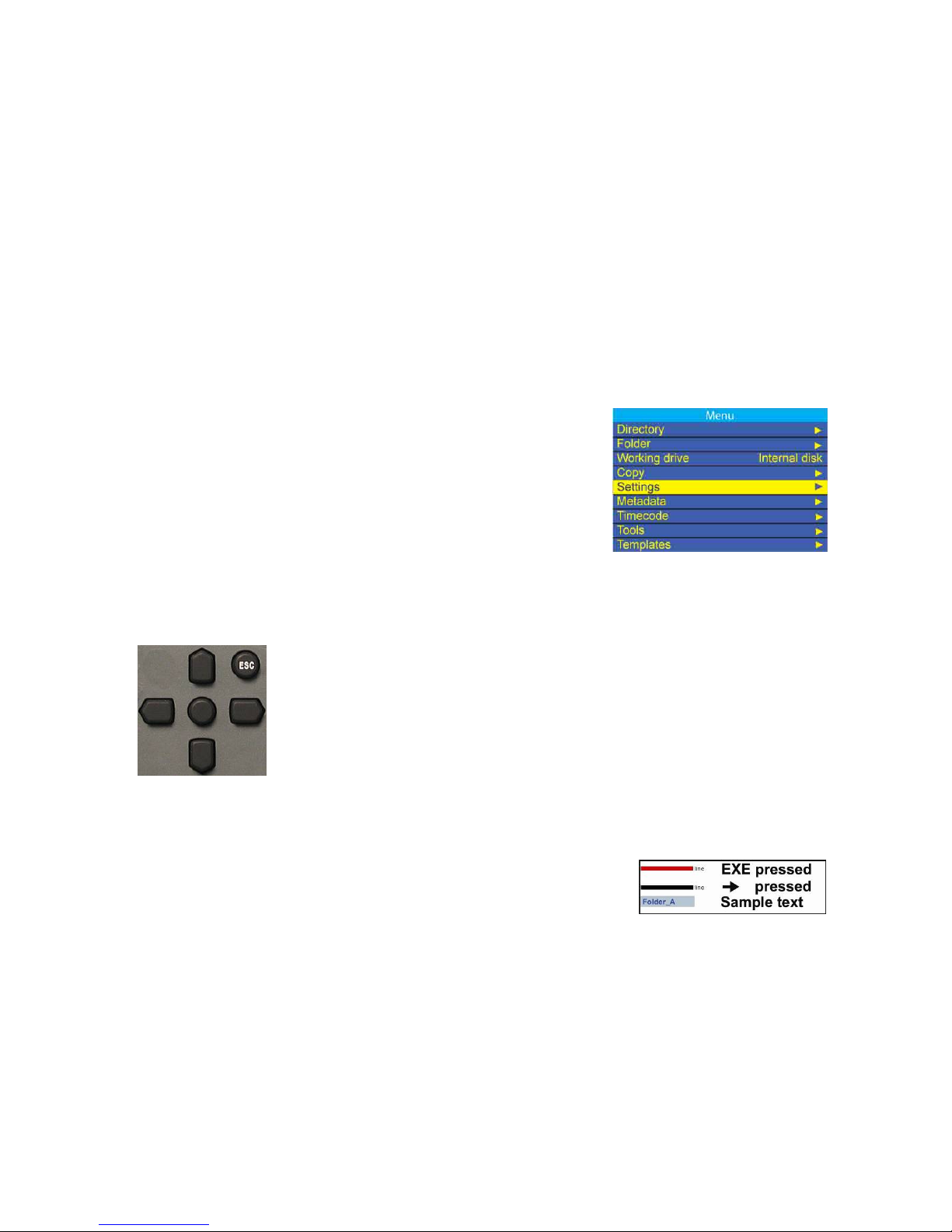
To enter into the menus, press the centre cursor key, and the “root” menu below will be displayed.
The ROOT menu
The current position (Settings) is highlighted in yellow.
Current selections for each menu are indicated on the right side of the
list wherever possible. In the example, one can see that the Internal disk
(HDD) is selected as the working drive. If a setting is not standard (i.e.
line output level has been set using the headphones pot, or a value
defined in an external template) then no value will be indicated on the
right side of the display.
Navigation through the various menus is made using the Up, Down, Left and
Right cursor keys.
To move one step backwards or to quit the menu mode, press the Escape
key. Holding the ESC key pressed will jump completely out of the menus to
the status screen.
Access any menu position with the right arrow key and the display will
indicate the currently selected setting / value. To choose an alternative, either
use the up or down arrow keys, or press the right key to display the sub-
menu of the selection.
Pressing the centre “EXE” key will activate the selection.
Note: In the menu illustrations of this manual, the horizontal black lines
between the menus shows that the right key was pressed to go to
the next sub-window, the red lines shows that the drop-down
window was obtained by pressing the EXE key.
Note: Certain parameters cannot be changed while the machine is in the “PRE-RECORD” mode (i.e. the
TEST position of the main selector). Such settings can only be changed when the main selector is
in the STOP position or the pre-record buffer is turned off.
Saving menu settings
All machine/menu settings are saved at the moment the machine is powered down. If the battery is
removed before the power OFF procedure is completed settings may be lost. To save the settings, select
OFF, and as soon as the indication “POW OFF” appears on the main display, select TEST or STOP and
the settings will be saved without stopping the recorder.
Chapter III
(Part 2 – The Audio)
July 2010 20
Page 21

Menu tree
The complete menu tree can be seen in Annex III at the end of this manual.
There are several menus, some with one or more sub-menus as shown in the overview version below. In
the list, the actual selections possible are not shown.
Directory-------- (Index list of recordings)
Folder------------ W here to record files
Working drive-- Internal HDD, CF card or USB drive
Copy------------- Manager and set-up
Settings--------- Audio settings----------------------------------------------Inputs
Pot. Assignment ---------------Channel offsets Mixer
Pre-record Mic display scale
Clock reference Line in level
Sampling frequency Reference generator
File type M/S decoder 1-2 and 3-4
File Naming Monitoring mode / boost
Max File Size Output Matrix
Colour theme (screens) Line / AES out source
Screen templates (display) AES out word length
Beep level Line out level
Loudspeaker
Automatic Skip
Start/ Stop polarity
User Key programming
Meter programming
Metadata-------- (Entry and editing)
Timecode------- Generator (TC settings)
Synchronizer
Tools ------------ Media speed test
Reformat (USB drive, CF or HDD)
Date and time
Automatic folder
Machine name
Keyboard layout (USB keyboard)
Software (defaults and updates)
Templates ------ 1 to 6 (store, name and recall)
The indications in the lower corners of some of the screen illustrations are not actually shown on the display
of the Nagra VI but are used in this manual to indicate the possibilities available to the user in each position:
“” means that the left / right arrow keys can be used
“” means that the up / down arrow keys can be used
“EXE” means that the centre key can be pressed
“ESC” means that the escape key can be pressed
User Programmable Keys
Menu shortcuts can be made using the programmable user keys U1, U2 and U3. (see Set-up)
Templates
Six templates which store complete recorder setup profiles of all the menu settings (except metadata,
working drive and working folder) are available. (Refer to page 63 for a full explanation of the templates and
Annex V shows a complete template file in text format)
Chapter III
(Part 2 – The Audio)
July 2010 21
Page 22
CHAPTER III (Part 2) THE A U D I O
SETTINGS >> AUDIO
This section covers all aspects of the audio chain of the
Nagra VI from the explanation of the different set-up options
to the operation of the microphone inputs, limiters etc.
The menu explanations below are grouped together by theme
rather than a step-by-step path through the consecutive
menus.
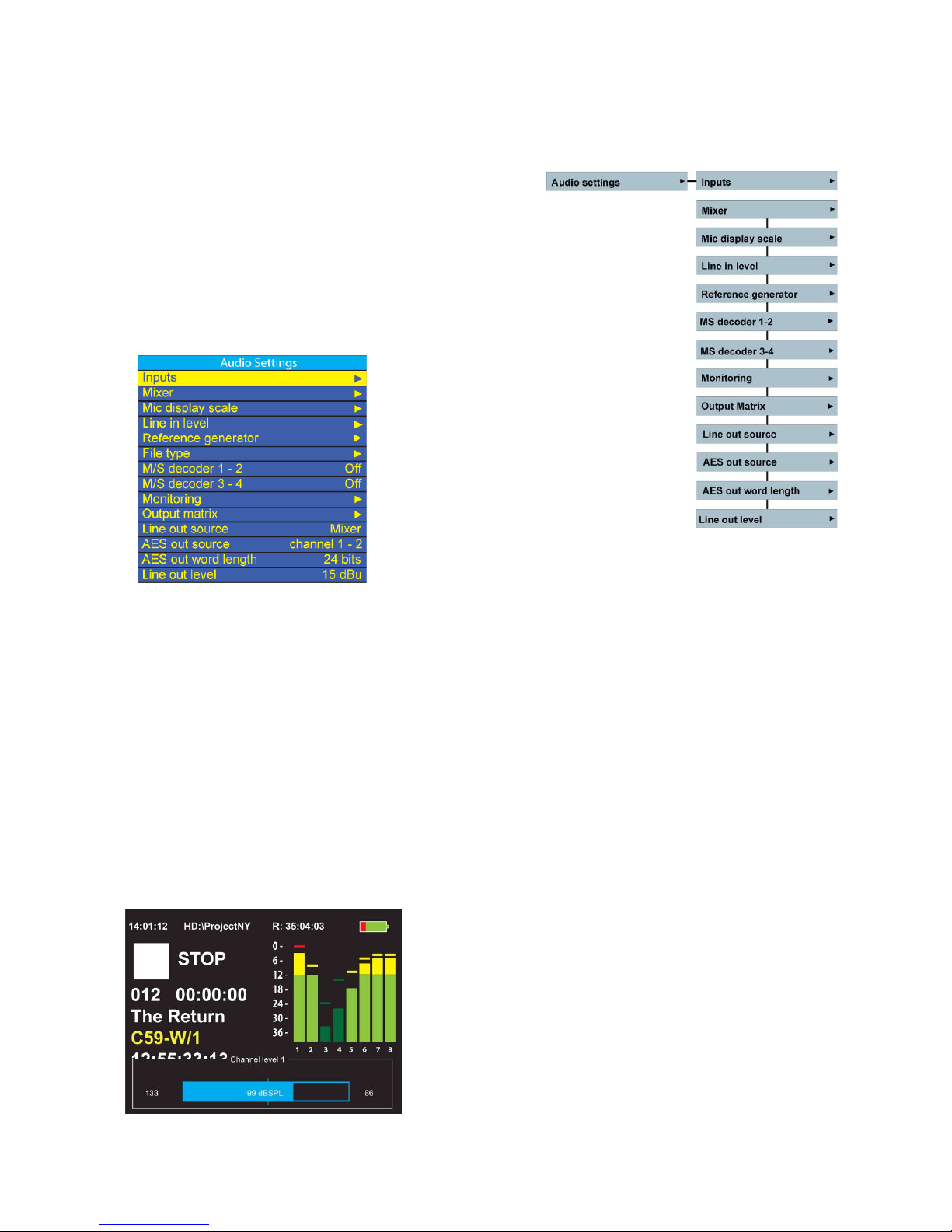
The audio settings
screen will show
currently selected
values wherever
possible.
The Audio menu
The audio menu gives access to all the principal features that will have a direct effect on the recordings.
This covers all the set-up possibilities for the inputs and outputs, as well as additional mixer facilities and
certain monitoring options. Each of the different sub-menus is covered below in more detail. Once a basic
grasp of the menu system has been achieved the overall understanding becomes very straightforward.
Audio level Adjustment and indications
The audio levels are indicated on the main display on the vertical bar graphs. In the picture below, channels
2 and 3 are in a darker shade because they are NOT armed for recording. The ballistics of the level meters
corresponds to those of a modulometer as on previous Nagra models. As soon as a potentiometer is
moved, the signal level is instantly displayed on the bottom of the TFT display as a blue “fuel gauge” with
the corresponding input number and audio sensitivity in dB SPL clearly indicated.
The scale of this display is changed according to the sensitivity
selection made in the Mic display scale menu, to give an
accurate sound pressure level indication according to the
specific microphone being used. The left end of the fuel gauge
is a digital fade area, and no dBSPL indication is shown in this
region.
While the potentiometer is being adjusted, two small vertical
lines on the outside edges of the fuel gauge can be seen to
indicate the position the potentiometer was in prior to being
touched. This indication is very useful to return the pot to the
previous position, especially if it was moved accidentally.
Chapter III
(Part 2 – The Audio)
July 2010 22
Page 23

The audio input signals for the 4 microphone pre-amplifiers are also indicated on the three LED’s mounted
above each of the input pots. The first led comes on at a signal level above -40 dB.
The yellow led will light when a signal of -12 dB is attained and the red led will indicate a level of -1 dB or
above.
The maximum levels (hold MAX) can be seen at any time by pressing the UP arrow key.
The maximum value can be reset by pressing the UP and DN keys simultaneously.
It is possible to record 0dBFS throughout the whole range of the potentiometer without risk of saturation
while the dBSPL value is displayed (Not in the digital fade area).
AUDIO INPUTS, OUTPUTS AND MIXING
The Nagra VI has six independent audio line inputs labeled 1 through 6.
Inputs 1 – 4 are equipped with high quality dynamic and condenser microphone pre-amplifiers.
Inputs 5 – 6 also double up as two digital inputs marked AES A and B.
The audio chain of the Nagra VI will accept audio frequencies up to 45 kHz, and this can be recorded
assuming the 96 kHz sampling frequency is used.
6 Line inputs
The inputs are selected to LINE operation in the Audio Settings menu. The six line inputs of the Nagra VI
will accept up to +24 dBu signal levels, and the input level is adjusted in the Line in level menu screen in 3
dB steps from – 6 to + 24 dB. The potentiometers on the front panel can also be used to adjust the line
input levels, but they need to be defined for this function in the pot assign menu first. The currently selected
input source selection “L” for line or “M” for microphone is clearly shown on the machine status display.
4 Microphone inputs
The four microphone inputs can be selected to one of three different sensitivity settings, of 2.8 mV/Pa,
10mV/Pa or 30 mV/Pa (Version 1 audio circuit only has the first two of these sensitivity settings available) in
the inputs settings menu via the main screen, depending on the sensitivity of the microphones being used.
Changing this selection will automatically change not only the input sensitivity selection, but will also switch
in and out the high quality dynamic transformers used to increase the signal-to-noise ratio when using
dynamic microphones in the 2.8mV/Pa position. It is also possible to turn on a +48V phantom power supply
on each of the four microphone pre-amplifiers.
Once the corresponding microphone type selection has been made, the input sensitivity of the pre-amplifier
is adjusted using the corresponding potentiometer on the front panel. The potentiometers, although digital,
use a special zipper noise suppression system, and behave in the same manner as traditional analogue
potentiometers.
The indications 2.8, 10 and 30 mV/Pa correspond to the sensitivity of the pre-amplifier, and this is an
international norm. If a microphone having the same sensitivity (i.e. 10mV/pa) is connected to the input set
to 10 mV/Pa this means that -9dBFS will be indicated on the meter when the pot turned fully clockwise for a
level of 74 dBSPL (which = 1µBar or 0.1 Pa) on the diaphragm of the capsule in the microphone.
Do not confuse the sensitivity of the input of the pre-amplifier with the sensitivity of a particular microphone.
The input of the Nagra VI has a sensitivity of 2.8, 10 or 30 mV/Pa depending on the setting.
For some examples:
A microphone with a sensitivity of 10mV/Pa connected to the Nagra VI set to the same sensitivity:
at 0.1 Pa (1 µBar) will show -9 dBFS corresponding to 74 dBSPL
at 0.282 Pa (2.82 µBar) will show 0 dBFS corresponding to 83 dBSPL
at 1 Pa (10 µBar) will saturate the input by 11 dB and corresponds to 94 dBSPL
Chapter III
(Part 2 – The Audio)
July 2010 23
Page 24

2 Digital AES inputs
The two AES inputs are available and designated AES “A” and AES “B” and use the input connectors for
inputs 5 and 6 on the left hand side of the recorder. In the input setting menu either of the two AES inputs
can be allocated to any of the four pairs of audio tracks (1+2, 3+4, 5+6 or 7+8).
This is achieved by menu selections SETTINGS > AUDIO > INPUTS. Use the down arrow key to highlight
one track of the pair of tracks that you wish to route the AES inputs to. Press the centre key and the
CHOOSE INPUT menu will appear. Now select either AES A or AES B and press the centre key and the
selected pair of tracks will record the AES signal fed into input socket 5 or 6 depending whether AES A or B
has been selected. As soon as the selection is made the recorder will expect an AES signal at the
appropriate input connector. If it is not present then the yellow error LED will double flash.
It is very important to remember when using an AES input to set the reference frequency of the recorder to
the incoming AES signal. If the Nagra VI and the incoming AES signal are not in perfect sync then “slipped”
sample errors will occur.
To do this go to the SETTINGS menu CLOCK REFERENCE and select the AES input in use (A or B) and
select the sampling frequency of the incoming AES signal. Otherwise the internal clocks of the Nagra VI will
not be synchronous with the incoming AES signal causing clicks on the recordings.
If both AES inputs are being used at the same time it is necessary that both sources are set to the same
sampling frequency and the clocks of the two AES devices are locked together, as the Nagra VI can only
synchronise to one AES signal. Most AES devices have the facility to both output a clock signal, and, accept
an external clock signal. The AES device connected to the AES input of the Nagra VI must be selected as
the reference for the Nagra VI. The clock signal of this external device should also be fed to the clock signal
input of the other AES device in use. That way the two AES signals and the recorder will be synchronous.
Selection of these inputs to AES will cause the letter “D” (digital) to be shown below the modulometer
display for the channels selected to digital inputs.
Chapter III
(Part 2 – The Audio)
July 2010 24
Page 25
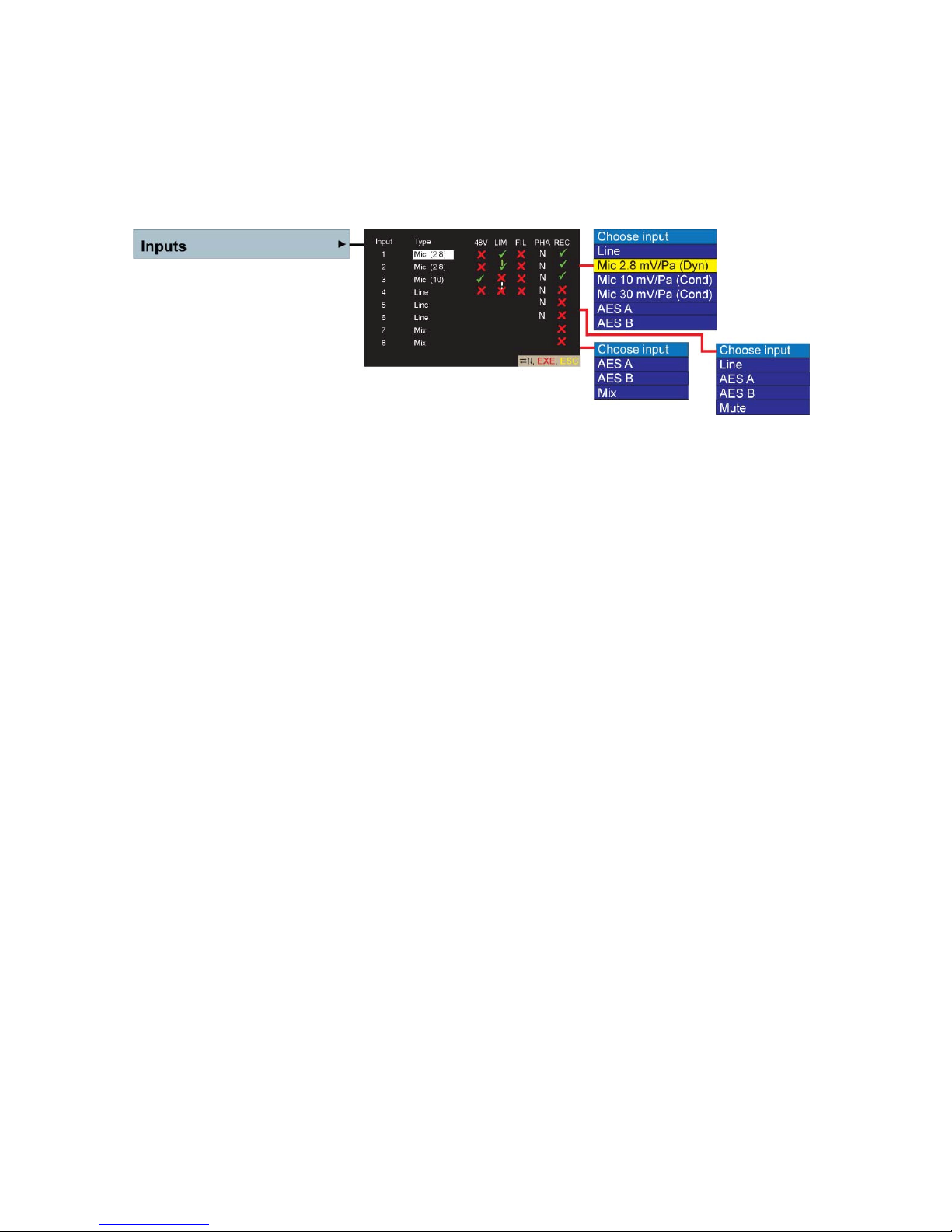
The Input configuration screen (Matrix)
The inputs screen (matrix) is used for the configuration of the audio inputs. The channel-to-track
relationship is such that, when in the analogue mode, each of the inputs is fed to its own track carrying the
same number as the input, thus allowing microphones 1, 2, 3 and 4 to be recorded on tracks 1, 2, 3 and 4
and the additional line inputs 5 + 6 to be fed to tracks 5 + 6. Channels 7 and 8 are principally used to record
the mix (of 1 to 6) but they can be used as additional digital inputs is a mix is not being made.
Use the up / down / left / right and centre EXE keys to move around the display and make the selections.
Highlight the input type and press the EXE key to display the sub-window shown above.
For inputs 1 to 4:
Analogue Line, Microphone or AES digital signals can be chosen. If microphones are chosen, then
Phantom +48V powering, the use of limiters (ganged or not), the low cut filter activation as well as the
normal or inverted signal phase can also be selected..
If digital inputs are to be selected then each pair of inputs can be selected to either AES “A” or “B” as
desired.
Warning: If an input is connected asymmetrically while the +48V phantom supply is active in the
2.8mV/Pa position this will cause the input to burn out. For this reason the +48V is
automatically disabled when the 2.8mV/Pa position is selected as a safety precaution. It
can subsequently be reselected if needed.
48V: This is the Phantom +48V powering of the chosen microphone input. Press the centre key
to turn ON (√) or OFF(X). This mode will cancel automatically if the 2.8mv/Pa (transformer)
sensitivity is selected, but can be reselected if desired. This is to prevent accidental
damage to the inputs if an asymmetrical connection is made. It can be re-selected to allow
use of a very low output condenser microphone in the 2.8mV/Pa dynamic position if
desired.
LIM: Analogue limiters are selected in the same manner and can be ganged (1+2) or (3+4) by
selecting the “¦” sign between the 2 channels in the limiter column. A solid green line means
that the inputs are ganged, and an interrupted red line means not ganged.
FIL: Turns the vortex (Wind) filter located in the preamplifier on or off.
PHA: The phase of an input can be inverted and is indicted by “N” for normal and “I” for inverted.
If the channels 5+6 are set to the mix position then the phase selection is no longer
relevant and turns grey on the display.
REC: This is the channel “arming” selection. It is in parallel with the selections in the file format
menu and indicates which channels will be recorded on the Nagra VI.
For inputs 5 and 6:
Only analogue Line or AES inputs can be chosen. A mute position is added in the event that the user has
already used input 5 or 6 for an AES signal for another pair of channels, allowing the “unused” channel to
be muted.
Chapter III
(Part 2 – The Audio)
July 2010 25
Page 26

For inputs 7 and 8:
On inputs 7 and 8 the “MIX” option is added to the list of choices in the drop-down menu, allowing the
output of the internal mixer of channels 1 – 6 to be recorded.
In the above picture, inputs 1, 2 and 3 will be recorded and they are set to the dynamic microphone mode
and the audio limiters activated and “ganged” together on inputs 1 and 2, meaning that if one of the
microphone input limiters is activated then the other will react in exactly the same manner limiting the
second input, to maintain the stereo image. Input 3 is set to the sensitivity of 10 mV/Pa with the +48 V
phantom power supply applied.
Note: If the symbols below 48V, LIM, FIL and PHA appear in grey colour (X) on this screen, it indicates
that the mode can not be changed due to the input type selection. (Example: 48V cannot be
switched on when the input is set to Line mode).
Microphone input limiters
All four microphone inputs are equipped with audio limiters. These limiters can be turned ON and OFF in
the audio settings menu in the same manner as the phantom power supplies and filters. These audio
limiters are embedded in the microphone pre-amplifier and are designed to limit the audio gently without
causing the side effects often inherent in audio limiters. The limiters for channels 1 + 2 and 3 + 4 can be
ganged together as pairs so that if one limiter is activated the other one in the pair will be activated
automatically in the same manner. Below the operational point of the limiter, the quality of the audio will not
be affected in any way. The audio limiters and indication led start to operate at -8 dB, and from the range of
-8 dB to -2 dB they compress the audio by 36dB.
The activation of the limiters is shown by the yellow led on the front panel above each of the input
potentiometers. When the limiters are ganged, then a green link line is shown between the two indications
on the main status display and inputs screen.
Input filters
Unlike most other pieces of equipment, the filter in the Nagra VI is embedded in the very front-end of the
microphone pre-amplifier. It is a vortex filter specifically designed to give ultimate protection against wind /
boom microphone noise. This filter is designed to allow the Nagra VI to be used in the most difficult
conditions on location.
The input filter on the Nagra VI is a hardware filter and is therefore not software programmable. The reason
for this choice is simple. A software programmable filter is a digital filter in the heart of the digital part of the
audio chain. Wind noise coming into the pre-amplifier will already have done its distortion and overloading
directly in the pre-amplifier long before it gets to the digital filtering stage. The filters in the Nagra VI roll off 3db at 250 Hz and then at 12 dB per octave. If an alternative curve is required, then provision is made on
the input circuit board to add capacitors accordingly and the necessary values can be supplied if necessary.
The filter can be activated for each pre-amplifier in the input settings menu and this activation is indicated
on the status screen by a green “Tick” below the bar graph level displays.
Chapter III
(Part 2 – The Audio)
July 2010 26
Page 27
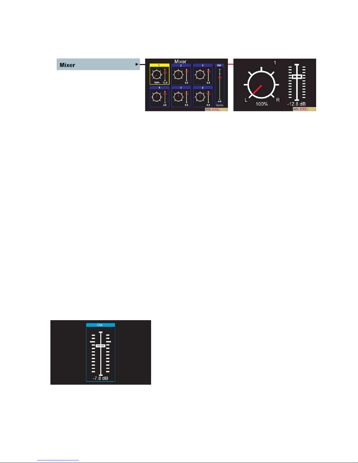
The Mixer menu
The internal mixer of the Nagra VI is designed as a 6 to 2 mixer where the inputs of channels 1 to 6 can be
mixed and then sent to the outputs or recorded on tracks 7 and 8.
In the Audio Mixer display the inputs can be selected one by one, and the level and pan position for each of
the inputs can be adjusted as desired using the up / down + left / right keys respectively.
Pressing the L/R keys simultaneously will toggle the pan to the fully left, fully right and center positions.
Likewise, pressing the Up + Dn keys will reset the fader to the maximum position at the top of the scale,
and a second press will go to the bottom of the scale.
It is possible to assign any of the four pots to control the mix in the pot assign menu. In this case, the
Up/Down keys are no longer active.
To record the mix onto the Compact Flash card, simply select the channels 7 + 8 in the copy menu to (√)
and channels 1 – 6 to the (X) then only the mix will be copied to the CF card. Of course, this mix will also
remain on the hard disk along with the primary or “ISO” tracks.
Beneath the output level slider, the mixer can be set to Stereo (as shown) or MONO operation by pressing
the execute key. In the mono position the pan feature is deactivated.
Playback mixing
The Nagra VI offers the possibility to mix 6 audio tracks using the internal mixer during playback. The
resulting mix can be fed to the audio outputs for recording onto another two channel device.
Audio monitoring of the mix output (to the line / AES outputs) can be selected by setting all the headphone
monitoring switches to the OFF position as long as “Mix if mon. off” has been selected in the monitoring
menu.
Mixer Output Level
The output level of the internal mixer can be adjusted using the “fader” on the right of each of the mixer
screens. The output gain can vary from +12dB to -46dB. This gain control fader can be attributed to the
headphone potentiometer using the pot assignment menu.
A small white horizontal line shows the “0 dB” point. If the
headphone pot is not attributed to this function then the level is
altered using the Up / Down arrow keys. Pressing them
simultaneously will toggle between MAX, MIN and pressing the
Left / Right keys simultaneously will jump from the current
position to 0 dB. The current output level of the mixer is shown
at the bottom of the fader.
Chapter III
(Part 2 – The Audio)
July 2010 27
Page 28
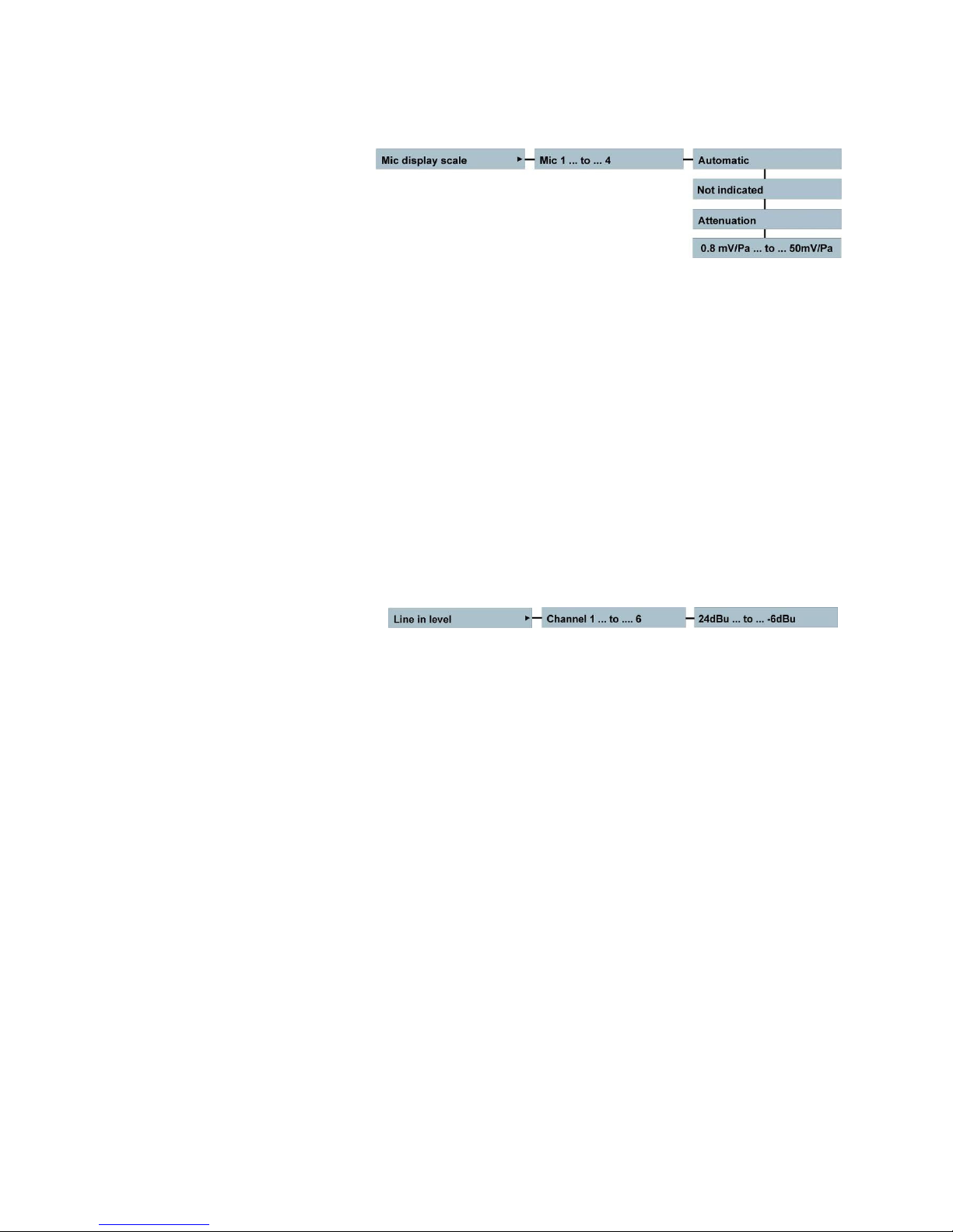
Microphone display scale selection
The microphone display scale menu permits to adjust the scale of the level indication “fuel gauge” so that it
will correspond to the actual dBSPL value according to the specific sensitivity of the microphone being
used. If the sensitivity of the microphone is known (supplied by the manufacturer in the technical
specifications of the microphone), select the corresponding sensitivity for the microphone. The correct
dBSPL indication will now be shown as soon as a potentiometer is touched. If the microphone sensitivity is
unknown, select “Not indicated”, and the “fuel gauge” will no longer appear when the potentiometer is
touched.
In the Automatic position, the sensitivity selected in the inputs menu will be used as the scale for the fuel
gauge.
If Attenuation is selected, then the indication will be in dB’s from 0 when the pot is touched.
If a particular potentiometer is assigned to more than one input gain, then when the blue fuel gauge is
indicated it will only show the corresponding level in “dB” rather than “dB SPL” if their sensitivity settings are
different.
Note: This selection will NOT alter the actual sensitivity of the pre-amplifier which is adjusted using the
potentiometer for the corresponding input.
Line input level adjustment
The analogue line input level for each input can be adjusted via the menus in fixed 3 dB steps or
continuously variable using one of the pots on the front of the recorder assuming it has been assigned in
the pot assign menu. The available range from the menu is 30 dB from 24 dBu to -6 dBu in steps of 3 dB.
Chapter III
(Part 2 – The Audio)
July 2010 28
Page 29
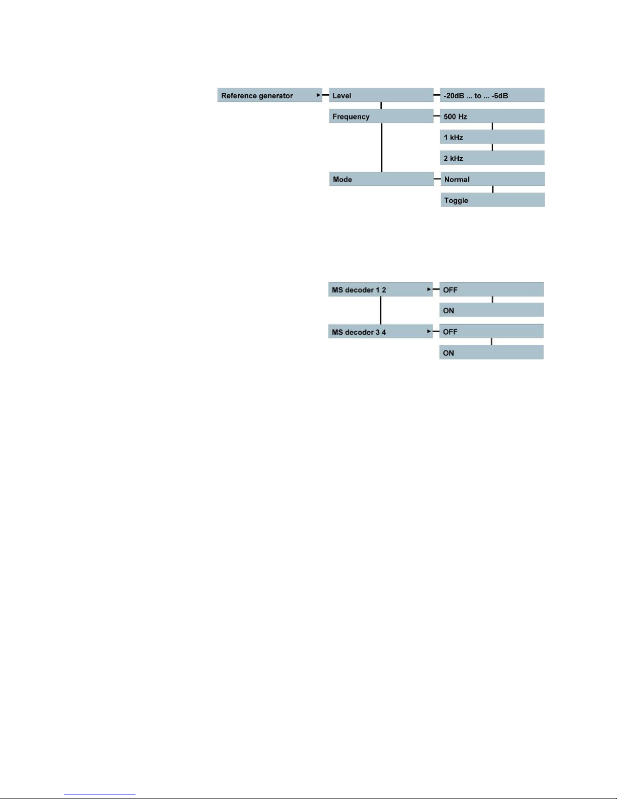
Reference generator menu
If the REF snap-switch is pushed down, the reference signal will be activated. In the REC position of the
main selector switch, this signal will be recorded on all selected “armed” channels. The level can be
adjusted from -20 dB up to -6 dB. The reference frequency can be selected to 500 Hz, 1 kHz or 2 kHz. The
operational mode of the REF switch can be set to Toggle ON and OFF upon each consecutive press. In the
NORMAL position the reference signal will only be present while the button is held down.
M/S Decoders
As the Nagra VI has 4 microphone inputs, two M/S decoders are available. The M/S decoder only acts on
the headphones and not on the outputs (unless the outputs have been set to the monitoring output mode in
which case the M/S decoder will also affect the outputs). This is used to decode an M/S microphone signal
into normal left / right signals for stereo monitoring.
Chapter III
(Part 2 – The Audio)
July 2010 29
Page 30

Headphone outputs
The Nagra VI is equipped with two parallel headphone outputs. The signals fed to these outputs, depends
on the positions of the monitoring matrix switches above the main function selector. The headphone level of
both outputs is adjusted using the headphone level pot on the front panel.
The gain of the headphone output and loudspeaker can be digitally increased by +6 dB or +12 dB if required
in the monitoring boost menu.
This is a digital amplification and therefore if set to +6dB the headphone amplifier will start to be overloaded
for signals reaching a level of -6 dB and likewise -12 dB if the +12 dB selection is made.
Pressing the headphone volume control button will give a mono signal centered on the headphones for as
long as the button is pressed.
The monitoring mode allows the user to select the Mixer as the monitoring source or channels 7 and 8 if a
mix is not being made. (in a mix situation these two outputs will be identical.)
Note: Increasing this audio level may cause hearing damage and is entirely at the users’
responsibility.
Output Matrix
The output matrix allows the user to define which of the 6 tracks is fed to the XLR (and AES) outputs, and
on to which channel of the output. This enables the user to feed out a signal different from that of the
headphone outputs. For this to be enabled the ANALOGUE and AES outputs selection (below) must be set
to the OUTPUT MATRIX position.
Line and AES output sources
Chapter III
(Part 2 – The Audio)
July 2010 30
Page 31

A high quality analogue output is located on the right side of the recorder on the two XLR connectors. It can
be set to feed out channels 1 + 2, 3 + 4, 5 + 6, 7 + 8, Monitoring output, the output matrix and the mixer
output as desired, using the menu. The principal AES output can also be set in the same manner. When in
the monitoring position, the signal on the line output XLR connectors is in parallel with the headphone
outputs, and the audio feed depends on the position of the headphone monitoring switches located above
the main function selector on the front panel. When set to the Output matrix, the XLR outputs will
correspond to the settings made in the Output matrix menu above. Finally in the Mixer position the output
will be the resulting output of the on-board mixer.
AES output word length menu
The AES outputs can be set to 16 bits dithered if a recording or a playback was made in 24 bits allowing
copying of the files to another piece of digital equipment with a lower resolution. If the recording was already
16 bits, the output stays 16 bits, and the unnecessary dither is automatically switched off.
The XLR AES output will feed out a digital version of the analogue line output. That is to say it will switch
according to the setting of the line output menu in the audio settings. Two additional fixed digital outputs,
corresponding to channels 1 + 2 and 3 + 4, are available on the 9 pin extension connector.
Line output level adjustment
The line output level can be adjusted through the range of 21 dB in steps of 3 dB from 15 dBu to -6 dBu.
In the POT ASSIGNMENT menu it is possible to assign the headphone level control potentiometer on the
front panel to adjust the line output level.
Chapter III
(Part 2 – The Audio)
July 2010 31
Page 32

CHAPTER III (Part 3) THE M E D I A
DRIVES, FOLDERS, FILES, DIRECTORY Indexes / Takes
Definition of terms
This is an area which although logical and straight-forward can lead to some confusion if not clearly
understood. This section aims to clarify the different areas and explain the use of the different terms.
Term Definitions
Working Drive : The storage media where the recorded files are to be saved (or read in the event of
playback). This may be either the internal hard disk OR the removable compact
flash card.
USB drive : Any generic mass storage USB device which is connected to the USB host port on
the right side of the recorder.
Folders : Different “sub-directories” on a drive into which files can be recorded or played
back.
Working folder : The “sub-directory” name into which the recorded files will be saved on the chosen
media.
Directory : The list of recordings (indexes) in a folder
File : A broadcast wave format audio recording (multiple for monophonic)
File type : The recording format of the file to be recorded (Poly / Monophonic)
File name : The alpha-numeric name of the file to be recorded
Index : An entry in the directory of the folder
Index number : The actual ascending numerical number of the recording in a given folder
Take : A recording that will create one or several files (Poly / mono) and an index
Take number : The ascending number of the take associated to a specific film scene
Chapter III
(Part 3 – The Media)
July 2010 32
Page 33

The INTERNAL HARD DISK
The Nagra VI is delivered with an internal 120GB Hard disk. This can be replaced if desired but the new
disk must be a 2 ½” Parallel ATA type (PATA) of any size up to a maximum of 2 Terabytes. Equally the
internal disk may be completely removed (physically disconnected) if the machine is to work in extreme
conditions (for example at -30°C) or perhaps under severe vibration, and hence only the CF slot (or USB
drive) will be used for recording. The internal drive may also be replaced by a solid state drive if desired.
The internal drive is considered as the “safest and fastest” media, and we recommend that it should be
used as the working drive whenever possible. Using the external drives as the principal media runs risks of
lower quality media, accidental disconnection, climatic variations and lower communication speed, which
can bring all sorts of possible real time problems. The official identification number of the internal drive can
be seen in the Tools/Software/About menu. The id number of the Western Digital internal 120GB drive
supplied in the machine is WDC 1200BEVE-00UYT0.
Compact Flash Slot
The compact flash slot on the Nagra VI can read any size compact flash card, but only cards larger than
128MB can be formatted in the Nagra VI. Certain compact flash cards, particularly the cheaper brands, may
run too slowly for the Nagra VI depending on the recording mode being used. It is recommended to always
test a new card type, using the media speed test menu, before starting an important recording session. The
official identification number of a compact flash card can be seen in the Tools/Software/About menu.
We recommend formatting the CF cards with the Nagra VI to ensure that the cluster size is 32kB which will
render them faster.
Beware of “Clone” cards on the market which are often cheaper cards branded illegally.
The USB Drive
The USB drive can be a generic USB mass storage device (External hard disk, USB key, or even a DVDRAM burner). It should be mentioned that there are hundreds of different types, makes and sizes of such
devices and the user should test the device first to be sure that it meets the necessary requirements for the
Nagra VI. Certain external USB Hard drives can consume too much power and are outside the official
specification of the USB norm. Such drives may cause the internal disk to crash when plugged in so it is
strongly recommended NOT to connect such a device during a recording, and to make trials beforehand to
be sure that the external disk works.
The DVD-RAM drive that we have used for the development tests is the model LG GE201U10 and is
commonly available for around $ 65.-
We have tested several different USB keys of varying sizes, without any problems, some however are quite
slow in operational terms. As a rule we do not recommend using the USB drive as the working directory for
principal recording as such devices are certainly less reliable than the internal Hard Disk of the Nagra VI.
The Media Speed test mode in the tools menu can be used to check the operating speed of all recording
media.
The WORKING DRIVE
The primary recording media is known as the “Working drive”. The Nagra VI is equipped with a built-in
120GB hard disk, and can also record to a removable compact flash card, both of which are considered as
“drives”. It cannot record “simultaneously” to both media. Either media can be selected as the working drive
in the “Working drive” menu. Once the working drive has been selected all recordings will be sent to this
drive and any playbacks will be made from this drive.
It is strongly recommended to use the internal drive as the working drive during recording, as it is faster and
safer than compact flash. Certain CF cards may not perform as well as others. If the CF card is to be used
then we suggest making several minutes of a trial recording first, to be sure that the card will perform well.
Selection of the CF and USB drive as the working drive is mainly for playing back files.
Chapter III
(Part 3 – The Media)
July 2010 33
Page 34

The FOLDERS
Today, high drive capacities allow backup of several jobs on the same disk, thanks to this feature, the
Nagra VI can handle multiple folders. This lets you organize your work by storing different jobs in different
folders on the same disk. The Nagra VI works with one folder at a time, which is called the “working folder”.
The default working folder is named “NAGRAVI”. All transport operations (record, playback, …) are done on
indexes located within the working folder. Each folder can contain up to 299 indexes. The Nagra VI can
manage up to 1000 folders per disk.
The Folders menu
In the folder menu, you can explore your folders in alphabetical order. With the right arrow key you can
scroll through the folder information which gives you the number of files and the size in gigabytes used by
each folder.
Note: The number of files viewed in the folder menu is the total number of ALL types of files found in the
folder. This number can be higher than the number of NAGRA indexes if another machine (PC,
MAC, …) has stored some other file types in the folder. (for example a .doc or .xls file)
Working Folder
The working folder or “sub-directory” is the location on the selected working drive where the recordings
(broadcast wave files) will be saved. Equally, any files to be played back must be located in the working
folder.
The working folder can only be chosen when the main function selector is in the STOP position. It cannot be
changed in PRE-RECORD, RECORD or PLAYBACK.
The default working folder is named “NAGRA VI” and is automatically created on the internal hard drive the
first time the recorder is powered up.
The working folder (on HD, CF or USB drive) is stored on the working disk (in the NagraVI.ini file). Thus, as
an example, if a certain working folder is used on a CF, and this card is put into another Nagra VI and CF is
selected as the working drive, the recorder will automatically find the correct working folder on the card.
Note: The working folder cannot be renamed or erased.
To erase or rename this folder, another working folder must first be selected.
Chapter III
(Part 3 – The Media)
July 2010 34
Page 35

Creating a new folder manually
To create a new folder, select the drive, press the centre key and select “Create”. A maximum of 31
characters can be entered.
A blank sub-window appears and using the up / down keys select the first character of the new folder name.
Use the right / left keys to jump to the next character position. When the full name is entered press the
centre key to validate.
Note: If after entering a new folder name the message “Create Error” appears, either the folder already
exists, or that the Nagra VI is currently connected via USB to a PC.
Creating a new folder automatically
The Nagra VI has the possibility to create a new working folder automatically each new day. The moment of
“New Day” is determined by the passage over midnight of the internal real time clock (RTC). The automatic
folder creation mode is activated in the Tools menu. Once activated, a new working folder will be created
automatically and seamlessly when the recorder is powered for the first time on the new day. If however the
recorder is switched on between midnight and 06:00 a.m. then the main display will ask the user whether a
new folder is to be created or not, in the event that a night shoot is happening and a new folder is no
needed. If the recorder is turned on after 06:00 a.m. then the folder will be created without asking the user.
If the function is deactivated, then all recordings will continue to be made into the same working directory.
An automatically created folder will be generated with the current DATE as the folder name in the format
YYYYMMDD. This can of course be modified by the user later if desired. Please also refer to the Tools
section where this menu is located.
Changing the working folder
To change the working folder, in the folder menu select the internal disk or Compact flash card, press the
right key and choose a folder. The Nagra VI is now ready to work with this folder. The currently selected
working folder has the sign “>” in front of the folder name. An error message “Used for Copy” will be
displayed if this is attempted during the copy process.
Copying a folder
To copy a folder, highlight the folder to be copied to the other drive, select Copy and press the centre key
and the copy starts. Copying a folder means that all indexes included in the folder will be copied. The
display will jump to the copy manager.
Rename a folder
To rename a folder, in the folder menu move to the folder name which you wish to change.
Press the centre key and select the RENAME function. Enter the new name and press the centre key to
validate.
Note: The working folder can’t be renamed: the message “Error folder in use” will appear, to do so, select
first another folder as the working folder. An error message “Used for Copy” will be displayed if this
is attempted during the copy process.
Erase a folder
To delete an entire folder, in the folder menu go to the folder name you want to delete. Press the centre key
and select the ERASE function. The message “Press Right to confirm” gives you a last chance to cancel
your request. If confirmed, the folder and ALL files and indexes inside are definitively deleted, however subfolders within the folder to be deleted will not be erased (an error message will be displayed as the folder
cannot be deleted as it is not empty).
Note: The working folder cannot be erased. To erase such a folder another working folder must be
selected. An error message “Used for Copy” will be displayed if this is attempted during the copy
process.
Chapter III
(Part 3 – The Media)
July 2010 35
Page 36

Viewing folders on PC via USB
If the Nagra VI is connected via USB to a PC then seen via a PC Explorer, it will immediately be recognized
as an external generic drive called “NAGRA_SOUND” of the computer, the following can be seen on the PC
screen:
Two removable storage devices will be detected (internal 120GB drive and the removable CF card (if
inserted)).
Selecting the internal HDD (in this example G:) the following appears:
The above example shows that 3 folders are present as well as a NagraVI.ini file. The NagraVI.ini file only
contains the information about the currently selected working folder.
Opening the “Nagra VI” folder shows the following:
This example below shows 2 monophonic recordings, each containing 6 channels.
Like a computer, the Nagra VI can create, copy, rename and erase folders on either the internal or external
drives. A folder name can contain up to a maximum of 31 characters in upper or lower case letters and / or
numbers from 0 – 9. Spaces are also accepted. All functions corresponding to the folders are made in the
menus.
Chapter III
(Part 3 – The Media)
July 2010 36
Page 37

The FILES
FILE TYPES
This should not be confused with the file format which is ALWAYS a Broadcast Wave file format with the file
extension “.WAV”
The Nagra VI can record either a single polyphonic file containing any (or all) of the eight tracks for each
.wav file, or it will record up to eight individual monophonic files – one for each track for every recording.
Both of the file types are standard .WAV files.
Polyphonic file recordings
Each time a recording is made a single “.wav” file will be created, and will include all the tracks
previously selected. This method of recording tends to be used in music recording applications and
generally when only a two track or “stereo” file is to be produced. The Nagra VI will create a
new file as soon as any file size reaches 2GB and when recording a polyphonic format, this will
occur every 13 minutes at 96 kHz 24 bit 8 track. It should be noted that certain audio post
production playback systems cannot handle polyphonic audio files. When copying polyphonic files
between drives on the Nagra VI all the tracks of a polyphonic file will be copied.
Monophonic file recordings
This method will record an individual file for each track selected, each of which is denoted by “_#”
at the end of the file name. This method tends to be the most popular recording format for cinema
applications, and has several advantages. Firstly virtually any playback system can read the files,
and secondly the maximum file size of 2 GB will only be reached only after 2 hours continuous
recording. When copying monophonic files between drives of the Nagra VI, individual tracks can be
copied if desired, by simply selecting the files in the copy menu.
The choice of one format or the other will have no effect on the amount of disk space used for a particular
recording. The file size does not change when recording monophonic or polyphonic file types. An eight track
polyphonic file will be the same size as eight individual monophonic files of the same recording.
(Monophonic or Polyphonic)
File type selection screen
The file type sub menu permits to select the channels that are to be recorded, the selection of 16/24 bit
resolution and whether the file format should be polyphonic or monophonic. The recording track selection
can also be made in the inputs menu along with the +48V, filter, limiter and phase selections.
Use the up down left right keys to highlight the channel, the bits or the phonic selection. By pressing the
centre key, the status can be changed. Once the changes have been made, press the ESC key.
Chapter III
(Part 3 – The Media)
July 2010 37
Page 38

File Sizes
The Nagra VI records audio using the standard FAT 32 (File Allocation Table) file format that allows the
audio files to be read by either MAC or PC. The FAT system limits any file to a maximum size of 4 GB
although many computer programs will not accept audio files larger than 2 GB. The Nagra VI will
automatically, and seamlessly, create a new file (or index) up to a maximum of 299, when the file size
reaches 2GB during any recording.
The Nagra VI can record 8 channels of 24 bits per sample audio at sampling frequencies up to 96 kHz and
this represents approximately 1 GB in 9 minutes. This means that a new file will be created about every 18
minutes. If a long duration recording is to be made, then it is strongly recommended to use the monophonic
file mode, and this will allow each track to have its own file each of which can go up to 2 GB. This calculates
approximately to 57 minutes per track of mono for 2 GB of memory space.
File naming selection
The file name is the alpha-numeric name given to each recorded file. The file name changes depending on
whether a monophonic or a polyphonic file is being made. The file name format can be selected from a predefined list of “name formats” made up of different combinations of data which are selected in the ”File
Naming” menu
When recording monophonic files the above name formats will all end with “_#” (# = track number) for
example Tape_XXX_1.wav (for the file corresponding to channel 1) and Tape_XXX_2.wav for the file of
channel 2 and so forth.
The “MachName” can be programmed by the user in the menu mode. The date and time settings depend
upon the settings of the real time clock and NOT the time code information. The “X” symbols above
correspond to the index number in numeric digits from 0 to 9.
The Index numbers
The index number is the ascending numeric number (or simple counter) associated to each recording in a
given folder. This can be from 001 – 299 maximum. Each recording will have a new index number, which is
automatically the one higher than the highest existing index number in the folder. If six channel monophonic
files are being recorded, then when index 299 is reached, there will be 1’794 .WAV files located in the
directory (6 x 299 = 1’794).
Note: It is not possible to record an index higher than 299 the machine will not go into record even if the
disk is not full. Even if index # 299 is the ONLY recording in the folder, the Nagra VI will still inhibit
additional recordings (“Directory full” will be displayed).
The Take numbers
The take number is the number of the actual “take” on the film set and is directly related to a scene number
of the production. In cinema applications scene and take numbers are often referred to as the “Metadata”.
The metadata entry of a new scene number automatically resets the take number to “001”. On the cinema
and default status screens of the Nagra VI scene and take numbers are clearly marked in yellow.
Example:
Chapter III
1A999XYZ/999
(Part 3 – The Media)
July 2010 38
Page 39

THE DIRECTORY is a list of Index numbers for all recorded files
This shows all the indexes (recorded files) in the selected working folder. The right side of the display gives
details of the highlighted index. Once an index is highlighted and the centre key is pressed, various actions
can be performed such as playback, copy, edit metadata delete or delete from this file up to …., renumber
or report creation, each of which is explained below.
Play Play back the selected index. To stop the playback, press the centre key once more and
the sub-window will show STOP instead of Play.
If playback of a track recorded at a sampling frequency other than the currently selected
frequency is attempted then Nagra VI will temporarily change to this sampling frequency.
It will automatically revert to the internally selected frequency if TEST or PRE-REC or REC
are selected.
Copy to CF Will copy an index from the working directory to the compact flash card or USB drive.
/ USB The same folder name will also be created on the receiving media if it does not already
exist. To copy multiple indexes, select the first index # to be copied and press the centre
key. A new window appears allowing entry of the last index # to be copied. Use the up /
down and right keys to enter the index #.
If no changes are made on the second entry #, only the selected index will be copied.
Example: “Copy from 002 to 002” will copy index 002.
Press the centre key to start copying and go to the Copy manager to watch the copy status.
The copy function is also authorized during recording.
Note: If the message “Copy error” appears, a problem has occurred during the copy
process. For example, the index(es) already exist on the destination drive or the
other device is not present. Refer to the “COPY” menu for more details.
Edit Metadata Pressing the centre key will jump to the metadata screen and allow metadata notes of up to
64 characters and modification corresponding to this index to be modified.
The metadata of the copy (if the autocopy function is active) will also be altered.
Delete Index Delete current index. Press the centre “EXE” key to activate the command. This command
is followed by “Press right to confirm”.
An accidentally deleted index can be reconstructed using a PC in the same way as a
computer file is retrieved, assuming NO recording OR renumbering has been performed
since the erasure took place. However this cannot be guaranteed as it depends on the
fragmentation / usage of the disk – in the same way as a lost computer file may not always
be successfully retrieved. The delete function is also authorized during recording, in case
that more space is suddenly needed on the disk during a recording.
Delete… To delete multiple indexes, select the first index to be deleted and press the centre key. A
window appears allowing the entry of the last index # to be deleted. Use the up / down and
right keys to enter the index number and press the centre EXE key to delete.
This command is also followed by “Press right to confirm”.
Renum. Executing this function will renumber all the indexes from this point onwards
from here consecutively. This will only have effect if indexes have been erased from the disk
after this index number. Index numbers prior to this index will not be affected. This
command is followed by “Press right to confirm”.
Chapter III
(Part 3 – The Media)
July 2010 39
Page 40

Renumber all Renumber all the indexes in the directory consecutively starting from “001”.
This command is followed by “Press right to confirm”.
Note: The functions “Renumber”, “Renumber all”, and “delete…..” are NOT authorized
during recording, although “Copy” and “Delete” (a single take) are allowed.
Create report W ill generate a list containing all the directory information concerning the current working
directory. This information will be saved as a text file in the current working directory. The
file is in text format so that it can easily be edited on a computer. Moreover, “TAB”
delimitations have been used so it can be “Drag n’ Dropped” into a spreadsheet (such as
Excel) and the user can easily create a sound report with all the time code and metadata
information about each index.
The following information is generated in the report:
Index #
Duration of the index
Date and time of recording
Project name
Scene #
Take #
Time code start value
Time code user bits
Time code frame rate
Audio sampling frequency
Digital word length
# of channels recorded
Track names 1 - 8
Notes
A printed copy of a sample report is shown at the end of this manual under Annex IV.
Chapter III
(Part 3 – The Media)
July 2010 40
Page 41

THE METADATA
Metadata is the term that has been given to the additional information recorded in connection with a
particular file, in conformity with the iXML agreed standard. Generally metadata is used in cinema
productions and allows a whole host of additional information such as the Production name, Scene
number/name, take number….. and a lot more to be recorded. (See Annex II at the end of this manual for a
list of the implemented iXML features).
Each portion of this data (Scene, names etc) can be edited using the main display of the Nagra VI. This
additional information is recorded at the “head” of each file which is an additional “Chunk” of information and
is interpreted along with the audio file. It should be noted that post production systems or digital
workstations that cannot read the BWF file format will simply ignore this additional metadata information.
This sub-menu is used to enter all the metadata for a project. By using the up / down / left / right keys,
highlight the desired area and press the centre key to show the editing window. Use the up / down keys to
select a character or number. Pressing the centre key will make the “Choose action” drop-down appear
when in the editing window.
Metadata entry
The Metadata can be entered either using a USB keyboard connected to the host USB port or using the
keys on the front panel of the machine.
Key (on Nagra) Function
Right Move to the next position in character chain
Left Move to the previous position in the character chain
Right + Left Insert a space/character in the chain
Up + Down Delete the highlighted character from the chain
Centre Confirm data entry
The following Metadata items can be user accessed:
Project name: Up to 32 alpha-numeric characters
Scene number: Up to 12 alpha-numeric characters (in yellow on Cinema and status screen)
Take number: 3 digits, auto-resets for new scene (in yellow on Cinema and status screen)
Track name: Up to 8 alpha-numeric characters for each track
False start: Will show “-F” following the scene number of the previous take
Pick-up scene: When activated will show “-P” following the scene number
Wild track: When active will show “-W” following the scene number
Note: Up to 64 alpha-numeric characters (Edit metadata mode from directory)
Accepted characters
The Nagra VI includes the following character set for file, project, directory, folder and template naming:
ABCDEFGHIJKLMNOPQRSTUVWXYZabcdefghijklmnopqrstuvwxyz!”#$%'()*+-=,./:;?0123456789
Other characters are not permitted.
Chapter III
(Part 3 – The Metadata)
July 2010
41
Page 42

Modifying the metadata
The metadata information can be “set” in the Generic data screen and modified during or after the recording
if desired in the “Current index data” screen. Alternatively, in the directory, highlight the index where the
metadata is to be altered and press the centre key. Select “Edit Metadata” and all the desired alterations
can be made. If the metadata is in grey (un-modifiable) text this is because the file was originally recorded
without this metadata “tag”.
Making alterations in the Generic metadata screen will change the global metadata settings that will be
recorded on the NEXT take and all consecutive indexes. To make alterations to the take currently being
recorded, simply select “edit metadata” from the directory display for the current recording and the changes
will be immediately taken into consideration while still in record mode. Modifications can also be made by
selecting the “Current index data” screen and making the modifications. This screen can be attributed to
one of the user keys for quick access if desired.
Note: If METADATA is modified and the Nagra VI is in “AUTOCOPY” mode then the copy will also be
modified under the condition that the copy is of exactly the same file size and number of channels
as the updated version.
False start
A false start of a take in cinema production is unfortunately all too common. If this happens, the recording
needs to start using the previous take number, and this is accomplished on the Nagra VI by simply pressing
the “Skip Backwards” key while moving the main selector to the record position. The metadata of the
previous take will then have the “-F” indication following the scene number to indicate that a false start was
made. This indication takes priority over the “-W” wild track information although both bits of information are
indeed written into the metadata.
If Metadata is altered or a False Start is made while the autocopy is active, the modifications will be taken
into consideration on the copy.
Wild track
A wild track is the term used for a recording that is not linked to any pictures but is generally linked to the
actual scene currently being shot. If “wild track” is checked, the suffix “-W” will be indicated after the scene
number. This cannot be combined with a Pick-up only one OR the other can be selected. When a wild track
recording is made the take number will increase on each new recording if multiple wild tracks are being
made.
Pick-up scene
A pick-up scene is the term used for the recording of a partial segment of a scene. If “pick-up” is checked
then “-P” will be indicated after the scene number. When a pick-up recording is made the take number will
increase as this can be considered as a take except it is only a partial scene.
This cannot be combined with a Wild-track, only one or the other can be selected.
Note: The Pick-up scene tag is not a formal iXML flag and is simply added by the Nagra VI to the end of
the scene name. If the scene name already consists of 12 characters then the last two characters
will be replaced by “-P” if a pick-up is selected.
Chapter III
(Part 3 – The Metadata)
July 2010
42
Page 43

The COPY FUNCTION
The copy function has two principal functions which will be covered independently. The first is the
“AUTOCOPY” feature for making a simultaneous back-up of each recording, and the second is the copying
of files or folders at a later stage from one place to another.
With multi-media features of the Nagra VI, the need to copy indexes between the drives becomes obvious.
The Nagra VI makes this possible thanks to its powerful background copy process that can copy indexes
and folders even while recording.
How the copy function works
The Nagra VI uses its copy manager to manage a “copy list”, which can contain up to 20 items. Each index
or folder to be copied is added to this list as a copy “item”. A list item contains the drive, the folder name
and the index range to be copied. The copy list can be viewed and managed using the copy manager menu
and display screen.
As soon as an item appears in this list, the Nagra VI starts the copy process automatically in the
background and should require no further intervention by the user.
The items are copied to the destination drive maintaining the same index number and folder name. If the
folder doesn't exist on the destination drive, it is automatically created.
Copy menu and display
On the lower portion of the copy setup screen the tracks that are to be copied can be selected. In
Polyphonic recording mode ALL tracks will be copied regardless. In Monophonic recording mode any
combination can be selected. When a recording is started and an index with the same name exists in the
destination folder an error message will be displayed. In addition the destination of the autocopy can also be
chosen, to be the Internal disk, CF or USB drive.
Note: If the destination is set to the same media as the current working drive (i.e. HD when the internal
disk is selected) then the message “Copy Set-up Error” will be displayed as soon as the machine is
set to record.
Chapter III
(Part 3 – The Copy function)
July 2010
43
Page 44

Auto copy
The Auto copy feature can also be considered as an automatic back-up of the current recordings, and once
activated, requires no further user input.
The copy menu offers two options, Copy manager and Copy setup. Select Copy setup and move the cursor
to the Auto copy position and check the “autocopy” box by pressing the centre key. This will enable the
automatic copying of all recordings, into a folder bearing the same name as the current working folder on
the working drive. This folder will be automatically created on the destination, also selected on the copy set
up screen, if it does not already exist.
Note: In the event of a copy error, the auto copy will not be executed until the copy error has been
resolved, as the copy process has been interrupted. A corresponding error message will be
displayed.
If alterations are made to the metadata, or a false start is made, then the metadata will automatically be
corrected on the copy. This may even be done after the event on the condition that the destination file exists
on the drive and that it is of identical size as the new file and that it contains the same number of tracks.
Automatic copy of the MIX
If the mix feature is being used on channels 7 + 8 (8 only if set to mono) and only this mix is to be copied to
the compact flash card, then only channels 7 + 8 should be set to copy (as shown in the above picture). In
this mode the internal disk will maintain all 6 individual inputs and the mix and the CF card will only hold the
mix which may be useful for dailies in cinema applications.
Copying indexes
To copy one or more indexes from the working folder, go to the index you want to copy in the directory
menu using the arrow keys. Press the centre key and select the “Copy….” function. The left side of the
directory display will show the message “Copy from xxx to xxx” This is the index range to copy. For a single
index (example 002) it should be set to read “Copy from 002 to 002” If you want to copy more than one
index, edit the second number to extend the range. Pressing EXE will add this copy item to the copy list and
begin the copy process immediately. The display will simultaneously jump to the copy manager display so
that the status of the copy in process can be monitored. Once completed, the screen will mark “Idle”. Press
ESC to return to the directory display. To leave the copy manager while the copy is being performed, simply
press the ESC key to return to the main display. This will not interfere with the copy process which will
continue in the background.
Note: It may be possible that some index numbers, in the index range chosen to be copied, do not exist (if
files have been deleted). This does not generate an error. These index numbers are simply ignored
by the copy process.
Copying a folder
To copy a folder (and all the indexes within it), go to the folder name you want to copy in the folders menu.
Press EXE and choose the “Copy…” function. This will add this copy item to the copy list. The display will
simultaneously jump to the copy manager display so that the status of the copy in process can be
monitored. Once completed, the screen will mark “Idle”. Press ESC to return to the folder display. To leave
the copy manager while the copy is being performed, simply press the ESC key to return to the main
display. This will not interfere with the copy process which will continue in the background.
If you do not want to copy all indexes of a folder but just a few, you must first select this folder as working
folder and use the method described in the previous section to copy individual indexes or a range of
indexes.
Chapter III
(Part 3 – The Copy function)
July 2010
44
Page 45

Copy list
In the copy manager menu, all the un-executed copy items in the list are shown. They are listed in the order
that they will be executed. The top item is the copy process which is currently being dealt with. When the
copy item has been completed successfully it will be deleted and the following will move up the list.
Pressing the EXE key on an item allows you to REMOVE it from the list.
Removing the first item in the list is possible, stopping the copy of the current index, but the indexes that
have already been copied entirely are not removed. If the copy was stopped due to an error, removing the
first item will clear it and restart the copy on the next item.
COPY MANAGER
The copy manager display shows what the copy process is doing.
This example shows the copy manager screen currently copying a range of
indexes (004 to 010) from a folder named “ProjectNY” on the internal hard
disk to the compact flash card. There is only one “item” in this copy list.
Pressing the ESC key from here will jump back to the screen prior to entering
the copy manager display. Pressing the centre key will show the function
menu list with the different available operational options.
Operational modes of the copy manager
MODE DESCRIPTION
IDLE The copy list is empty, no copies are running, no errors on previous copy.
COPYING The copy process is running.
SUSPENDED The Nagra VI is in record mode and the current copy destination is the same drive
as the working folder (copy will always go to the other drive). The copy is
suspended to avoid file fragmentation on the disk and to guarantee you a reliable
remaining recording time.
Copy manager commands
This drop down menu appears when in the copy manager and the centre key is pressed giving
the user a choice of various different copy related operations to be performed.
Oops… Oops will remove the drop down menu and return to the copy
manager screen, following an accidental pressing of the EXE
key.
Retry Try to repeat this copy command again. This may be
necessary after creating space on a previously full disk /
card.
Remove Delete an item from the copy list
Abort Remove the current copy list item and continue copying the
next copy list item (if any).
Abort all Stop the copy action and remove all additional items from
the copy list.
Skip Skip this index and continue with the next index.
Skip all Skip this index and all subsequent indexes in this copy item.
The next two functions are only possible in event of the message “File already exists”
Overwrite Overwrite this index. The existing index on the destination disk is deleted
before the copy.
Overwrite all Overwrite this index. The existing index on the destination disk is deleted
before the copy. If another index of the current list item already exists on
the destination drive, it will be automatically deleted and overwritten
without warning.
Chapter III
(Part 3 – The Copy function)
July 2010
45
Page 46

The next function is available when the power to the Nagra VI was lost prior to finishing a copy. This is the
only function possible in this case.
Retrieve Retrieve the uncompleted copy list items prior to power off. This function
does not clear the error. Press EXE again to display the copy function list
describe above.
Copy error messages
While a copy is running in the background, you may be alerted by the error message “Copy Error” on the
bottom of the main display. This tells you that copy process has stopped and needs your intervention. The
copy manager screen will give you an explanation of the reason for the error. Error messages are displayed
as “Error: xxxxxxxx”: on the copy manager screen.
MESSAGE DESCRIPTION
Disk full The destination disk for the copy is full.
Card Full The CF card is full.
File already exists The next index to be copied in the copy list already exists on the
destination disk.
Power lost The copy was stopped due to a loss of power.
Creating folder Unable to create the destination folder.
Reading file Error reading source index / file.
Writing file Error while writing destination index / file.
Creating new file Unable to create destination index / file.
Deleting file Unable to delete an index / file (overwrite mode).
Copy set up error Destination for autocopy is the same as the working drive.
If an error is displayed, go into the copy manager display screen and the reason behind the error will be
indicated. Press the centre key and a selection of possible choices will be displayed:
General error messages
Certain short messages may appear on the bottom of the main display when an incorrect command is
executed. The message will explain the reason.
Example: the message “Error: must be in stop” will be displayed if an attempt to change the sampling
frequency is made while the Pre-record is active in the TEST position.
Chapter III
(Part 3 – The Copy function)
July 2010
46
Page 47

Solving specific copy problems
PROBLEM SOLUTION
“Disk full” Delete unnecessary folders/indexes on your destination disk. Then execute
the RETRY function.
“Card Full” Change the compact flash card. Execute the RETRY function. The
incomplete copy items will continue on this new card.
“File already exists” An index with the same number exists on the destination disk. Use either
the Skip function or Overwrite.
“Power lost” Execute the RETRY function to continue the copy process.
“Creating error” The destination disk is certainly either not present or not formatted. Insert a
formatted compact flash card.
“Reading Error” Initially use the RETRY function. If the error re-appears your index or your
disk may be damaged.
“Writing Error” Initially use the RETRY function. If the error re-appears your disk may be
damaged.
“Deleting Error” Initially use the RETRY function. If the error re-appears your disk may be
damaged.
Index with file attributes set to read-only can cause this error; this problem
must be resolved with a PC as file attributes cannot be altered using the
Nagra VI.
Other copy related messages
“Copying” Attempt to DELETE or RENUMBER indexes or SELECT, RENAME or
ERASE a folder while the selected indexes or folder is still in the copy list.
You have put the Nagra VI in power off and it has not yet finished to
copy, this is not an error message in this case (see copy and power off
section).
“List Full” The copy list can contain up to 20 items. This list is full and you can't add
another copy at this time.
“In Use” Folder destination in use. Attempt to copy to the working folder, this is not
allowed.
“Copy Error” A copy was stopped because an error occurred. See Copy error section.
“Copy set up error” The destination for the copy is the same as the current working drive. This
is not permitted.
Chapter III
(Part 3 – The Copy function)
July 2010
47
Page 48

Stopping a copy
To stop a copy, go to copy manager menu and press EXE to stop execution and use the “Abort” or “Abort
all” commands.
Copy and power off
If the Nagra VI is still copying and you don't want to wait for the process to finish. No problem! Put the main
selector to the OFF position, it will display the message Copying. The Nagra VI will finish all the copies in
the list, and will then power off automatically.
Later, it is possible to verify that the copy was completed correctly. Power-up the machine and select the
copy manager display. The “Idle” status tells you that the copy was completed without problem.
In the event of an error, the status will show it, as well as the number of the index being copied at the
moment the error occurred. In this case the copy list contains the remaining items. Press EXE and execute
the RETRIEVE function, this retrieves the incomplete copy list item when the Nagra VI was powered off.
You can now resolve the error in a normal way.
Note: After power off, the possibility to retrieve the copy list remains, as long as no new copies are added
to the copy list. When a new copy is added, the retrievable copy list is lost and the error is cleared.
Chapter III
(Part 3 – The Copy function)
July 2010
48
Page 49

CHAPTER III (Part 4) THE S E T- U P
The OTHER SETTINGS
All the other settings apart from AUDIO are covered below. They
correspond to the personalization parameters of the recorder, and are
all functions and features that can be stored in the templates.
The settings screen is shown below. Each of the sub-menus is
explained individually.
>>>>
The POTENTIOMETER ASSIGNMENT FEATURE
The pot. assignment menu makes it possible to assign any of the 4 principal potentiometers on the front
panel to one or more microphone inputs, to one or more mixer gain (Attenuator) controls, line input level or
to be unassigned and therefore have no action. The default setting for the potentiometer assign is to the
microphone sensitivity control of the inputs 1 to 4 with the corresponding pre-amplifier. The operation of the
headphone / loudspeaker potentiometer can also be attributed to either headphones, Line output level or
mixer output gain.
What the potentiometer assignment does
What this feature allows is to assign the function of each of the four potentiometers on the front panel. Each
pot can have a specific “function” such as Microphone sensitivity, line input level or mix gain and can also
be attributed to any particular input. For example, to pre-set the input sensitivity of each input and then use
a single potentiometer to control the mix without affecting the actual signal being recorded on the six master
tracks they can be considered as the “ISO” tracks and tracks 7+8 will be the mix. There are many different
combinations that can be used in this mode depending on the application and inputs being used.
The Pot. assignment screen
The different selections are made by simply pressing the centre key and if necessary selecting the desired
feature from the drop-down list.
Chapter III
(Part 4 – The Set-up)
July 2010
49
Page 50

In the example above: They are set such that potentiometer #1 controls the microphone input sensitivity of
microphone 1 potentiometer #2 is set to control the microphone sensitivity of microphone 2 and
potentiometer #3 is set to be the mixer gain control for 1 and 2 together. Potentiometer #4 is not assigned
and will have no action if turned. In this situation, displaying the mixer display and moving potentiometer # 3
will show the two mixer “faders” move together on the mixer display.
If no potentiometer is set to Mic, Mix gain or Line in, and no input is assigned to this potentiometer, then it
will automatically be set to “Not assigned” when leaving the display. When not assigned is selected the
indication is in grey.
The pot assignment selections can be made at any time even during record, making it possible to switch
between Mic input sensitivity and mix gain during recording. However it is important to remember that
making such a switch may cause sudden level jumps depending on the relative positions of the two pots.
The “MON” position is for the assignment of the operation for the monitoring output (headphone level)
potentiometer. This pot can be assigned to either “Phones & Speaker”, “Line Out” or “Mixer Output”. The
previous setting of the potentiometer will be memorized.
Pressing the Left and Right arrows keys simultaneously will momentarily set the potentiometer assignments
to the analogue inputs according to their selection in the inputs menu, allowing an input to be quickly
“trimmed” when the pots have been allocated to mixer functions without re-assigning them. This function is
not available when in the menu mode – as the L/R keys are used for other functions in the menu mode.
Note: The pots assignment selections are saved in the templates, and can be recalled as desired for
different applications.
Potentiometer offsets
When a single potentiometer is assigned to control two (or more) input sensitivity levels at the same time, it
is very likely that there is an offset in levels which, under normal circumstances will disappear when a single
pot is attributed to multiple inputs – all the channels will “jump” to the same level according to the pot
position. The Nagra VI allows offsets to be programmed in order to maintain the balance between each
input channel, so that differences in sensitivity settings for the different inputs will be kept when a particular
potentiometer is used to control more than one channel at the same time.
Once an offset is programmed between two pots, then this offset will be maintained when the master pot is
adjusted. If an offset has been programmed then a “*” will be shown next to the relevant channel on the
main display when the pot is moved.
The potentiometer offset screen is reached by moving to the right (arrow) on the pot assign display and
then pressing the EXE key. The offsets can be set for each potentiometer in steps of 0.1 dB. To reset a
specific offset to zero rapidly, simply press the UP and DOWN menu keys simultaneously when the
particular offset is highlighted. On an external USB keyboard the letter “R” will reset the specific value and
Ctrl + R will reset ALL offset values.
Pre-record function
The pre-record function stores audio in a closed loop file prior to recording, indicated by the flashing REC
led. When the main selector is moved from TEST to REC, the contents of the buffer will immediately be
recorded at the beginning of the recording as if the Nagra VI were already in record prior to the moment the
actual recording is activated. The pre-record time can be set from 1 second up to 20 seconds (max to 10
seconds at sampling frequencies of 88.2 – 96 kHz).
This feature is particularly useful while recording sound effects, where it is never certain of the exact
moment a particular sound will occur (Example: Thunder). With the pre-record active, the Nagra VI can be
switched to record as soon as the sound is heard, and it will still be recorded from the buffer memory.
Note: Certain operations are not possible when the Pre-record function is active. For example you cannot
change the working drive, working folder, sampling frequency…etc while in pre-record mode,
Chapter III
(Part 4 – The Set-up)
July 2010
50
Page 51

because as far as the recorder is concerned, it is already in the RECORD mode albeit “loop
recording” to the buffer, and such changes are not permitted in the record mode.
Chapter III
(Part 4 – The Set-up)
July 2010
51
Page 52

Clock reference
This is the reference frequency selection that tells the machine to which signal the internal clocks of the
machine are to be synchronised.
Generally the machine will be synchronised to its internal high stability stratum III crystal (MASTER
position), which will guarantee the correct sampling frequency. It is however possible to select another
external reference, by moving through the possible choices using the up / down keys.
If an external reference is being used then this signal must be stable. Pressing the centre key on any of
these positions will select the displayed choice as reference.
Selection Signal explanation
MASTER Machine is set to be “master”, all clocks are synchronised using the internal
stratum III high stability crystal.
MAS +0.1% As master but accelerated by 0.1% for NTSC applications
MAS -0.1% As master but slowed down by 0.1% for NTSC applications
EXT 44.1 External word clock on the extension connector at 44.1 kHz
EXT 48 External word clock on the extension connector at 48 kHz
EXT 88.2 External word clock on the extension connector at 88.2 kHz
EXT 96 External word clock on the extension connector at 96 kHz
AES A 44.1 External ref to be used is arriving on the digital input “A” at 44.1 kHz
AES A 48 External ref to be used is arriving on the digital input “A” at 48 kHz
AES A 88.2 External ref to be used is arriving on the digital input “A” at 88.2 kHz
AES A 96 External ref to be used is arriving on the digital input “A” at 96 kHz
AES B 44.1 External ref to be used is arriving on the digital input “B” at 44.1 kHz
AES B 48 External ref to be used is arriving on the digital input “B” at 48 kHz
AES B 88.2 External ref to be used is arriving on the digital input “B” at 88.2 kHz
AES B 96 External ref to be used is arriving on the digital input “B” at 96 kHz
PAL External video reference is on the extension connector in PAL 25 fps
NTSC External video reference is on the extension connector in NTSC 29.97 fps
NTSC 60 Hz External video reference is on the extension connector in NTSC 30 fps
Note: If any setting is wrong or outside the limit of ± 4%, the alarm LED starts blinking.
Chapter III
(Part 4 – The Set-up)
July 2010
52
Page 53

Sampling frequency
This selection is used to select the sampling frequency of the internal audio A/D converters, and to select
the necessary internal clock frequencies.
If a sample frequency such as 48’048 is to be recorded then simply set the sampling frequency to 48 kHz
and then set the Clock reference to Master + 0.1%. The same will occur for all other combinations.
File type selection screen
The file type sub menu permits to select the channels that are to be recorded, the selection of 16/24 bit
resolution and whether the file format should be polyphonic or monophonic. The recording track selection
can also be made in the inputs menu along with the +48V, filter, limiter and phase selections.
Use the up down left right keys to highlight the channel, the bits or the phonic selection. By pressing the
centre key, the status can be changed. Once the changes have been made, press the ESC key.
File naming selection
The file name is the alpha-numeric name given to each recorded file. The file name changes depending on
whether a monophonic or a polyphonic file is being made. The file name format can be selected from a predefined list of “name formats” made up of different combinations of data which are selected in the ”File
Naming” menu as follows:
MachNameXXX.wav TapeYYYYMMDDHHMMSS_XXX.wav
MachNameHHMMSS_XXX.wav Tape_Scene_Take_XXX.wav
MachNameYYYYMMDDHHMMSS_XXX.wav Scene_Take_XXX.wav
Tape_XXX.wav YYMMDD_HHMMSS_XXX.WAV
TapeHHMMSS_XXX.wav
When recording monophonic files the above name formats will all end with “_#” (# = track number) for
example Tape_XXX_1.wav (for the file corresponding to channel 1) and Tape_XXX_2.wav for the file of
channel 2 and so forth.
The “MachName” can be programmed by the user in the menu mode. The date and time settings depend
upon the settings of the real time clock and NOT the time code information. The “X” symbols above
correspond to the index number in numeric digits from 0 to 9.
If the iXML metadata of a file is altered, then the file name will be changed accordingly.
Chapter III
(Part 4 – The Set-up)
July 2010
53
Page 54

Max file size
This menu selection allows the user to determine the maximum size that any particular file will have. When
a file (or “files” in monophonic mode) reaches the selected maximum the Nagra VI will automatically create
a new index seamlessly. It should be pointed out that although the Nagra VI can handle files up to 4 Gb
(max. authorized in FAT 32) many editors, and other post-production devices will not handle them. This
feature enables recordings to be broken into portions suitable for other media.
Colour themes
The display of the Nagra VI can be set to various different display colour themes depending on individual
taste. The default colour is as shown in the four pictures on the “Screen templates” below. The night screen
turns all text blue and the second possibility is black and white, and the grey / red screen turns the menus to
grey and red.
Chapter III
(Part 4 – The Set-up)
July 2010
54
Page 55

The Screen templates
Four different displays can be selected for the standby (Status), recording and playback screens. The
“Standby” screen is the screen displayed when the Nagra VI is NOT in record mode (i.e. Stop, Test of Play).
When the main selector switch is moved from the TEST to the REC position the screen will change to the
pre-set selection.
The default screen is shown in picture 1 below and gives the most information.
The “Cinema” screen (2) has larger modulometers, and indicates all the information relevant to cinema
applications (Scene / take #, time code, etc.).
The meter screen (3) shows the modulometers only, over the entire width of the display.
The “music” screen (4) shows the modulometers, index number and duration only.
Pressing the “left” key will always show the default screen #1 temporarily.
Pressing the “right” key will always show the Meters screen # 3 temporarily.
The current operating mode, the file format, working drive / directory, remaining time, and battery / power
status are shown on all screens.
#1 (Default “Status” screen) #2 (Cinema screen)
#3 (Meter screen) #4 (Music screen)
Chapter III
(Part 4 – The Set-up)
July 2010
55
Page 56

The Beep function
The beep function of the Nagra VI can be used to alert the user to certain events. It consists of two musical
tones of “C” and “G” (“do” and “sol”) and is set to a level of -18dB. The following beep indications are
implemented:
do / sol = “OK” Function correctly executed and accepted
sol / do = Not “OK” Function NOT or PARTIALLY executed
do / do = Error (shown on main display)
do = New record command (including new take)
The beep signal will be heard on the headphone output and the internal speaker. It will also be present on
the line and AES outputs if they are set to follow the monitoring selections. The beep signal can be turned
OFF and be set to a level from -6 dB down to -36 dB using the menu.
The Loudspeaker
The internal loudspeaker on the top of the recorder can be turned on and off using the switch on the front
panel. Activation of the speaker depends on the menu setting. The audio signal to the speaker depends on
the settings of the monitoring matrix.
The loudspeaker menu has two positions: “Always ON” even during recording
“On play” playback only.
The level of the loudspeaker is adjusted using the headphone potentiometer, the gain of which can be
increased by +6 dB or +12 dB in the monitoring boost menu. This is a digital amplification meaning that the
signal will overload the amplifier if levels of -6db and -12 dB respectively are attained.
Automatic skip function
In the playback mode when the end of an index is reached, the automatic skip function will instruct the
Nagra VI to jump to the next index of the same sampling frequency in the selected folder and continue
playing back. When turned OFF the Nagra VI will simply stop once it reaches the end of the selected index
being played back.
START / STOP remote polarity
Permits to reverse the activation polarity on the 3.5 mm jack remote START / STOP connector. In the
“Normal” position, when the terminals are NOT short-circuit (open contact), the machine starts in record,
playback or chase depending on the position of the main selector, when the terminals are short-circuited
(contact closed), the machine will stop. Therefore changing this selection to the Inverted position will simply
reverse the operations above.
Chapter III
(Part 4 – The Set-up)
July 2010
56
Page 57

User Programmable Keys
The Nagra VI has three user definable keys U1, U2 and U3 on the front panel. These keys can be
programmed to short-cut the path to any of the menu positions. This allows the user to access three
different menu positions at the simple press of a button. Three additional programmable keys are available
when an external USB keyboard is connected. On the external keyboard, U1, U2 and U3 are attributed to
the function keys F1, F2 and F3 respectively and F4, F5 and F6 can also be programmed giving a total of 6
user programmable shortcut keys.
In the above illustration U1 is programmed to jump to the Inputs screen and U2 to the (generic) Metadata
entry, and U3 has been left unassigned, and on the external keyboard F4 is assigned to the Time code F5
to the mixer and F6 for rapid access to the metadata of the current index.
Programming user keys
On the user key programming screen, move the highlighted cursor to the user key to be programmed.
Press the centre key and the sub-menu will appear. Select the “Menu Short cut” position. The display will
change to read “Short cut to…”
Use the ESC key to exit and then enter the menus until the desired point is reached. Press the User key to
be programmed. From now on each time the user key is pressed the display will jump immediately to this
position.
The programming of the user keys is remembered when the power is lost and they are also saved in the
templates.
To clear a setting from a user key simply select “not assigned” and no action will occur when it is
subsequently pressed.
Note: While programming the User keys, it is possible to pre-set all short-cut keys to the “Short cut to…”
position and then navigate through the menus pressing the U1, U2 and U3 as desired on the
appropriate menu. It is not necessary to return to the programming menu for each key.
Meter Programming
The Meter programming feature allows the operator to set the parameters of both the bar graph meters on
the main display and the three LEDs above each of the microphone sensitivity potentiometers. The range or
“Scale” of the meters can be set to indicate from 0 to -30, -40 or -50 dB.
The red and yellow levels settings define at what level they are active. In the default position the red level is
set to -1dB and the yellow level is set to -12 dB and the scale range is 40 dB.
The Meter programming settings will be stored in the templates.
Chapter III
(Part 4 – The Set-up)
July 2010
57
Page 58

CHAPTER III (Part 5) THE T O O L S
The TOOLS SELECTION
The tools menu gives access to various different “utilities” within
the Nagra VI. These settings will not have any direct effect on the
recording. All settings relating to the audio portion of the recorder
are covered under the settings menu.
The different possibilities in the tools menu are described below:
MEDIA SPEED TEST
Many different manufacturers and types of media exist today, and they are of varying quality and price.
Some are marked as “rapid” or “High speed” etc. but this does not always mean that they are well suited to
Audio recording in real time. These “speed” related terms may sometimes actually only refer to the read
speed rather than the write speed. If a CF card is to slow, then it will create a disk error during the
recording. There are indeed also many clone copies of more expensive cards available on the internet,
which in most cases are poor quality slow speed cards. It is for this reason that we have implemented the
Media Speed Test mode, to allow the user to test different media to verify its suitability for use with the
Nagra VI, and to indicate the electronic digital “id” of the CF card being used. In the picture above the CF
card is a Sandisk SDCFM-1024, this is very useful to be sure that the CF card being used is not a low cost
“clone” or “fake” of a more expensive card.
Use the UP / DN key to toggle between the Media type and the Start position. When the media is highlighted, press the centre key to select the desired media to be tested. Press the centre key to start the
media test. The time taken for the test varies from one media to another and will take about 10 seconds for
the internal drive, but may take up to 1 minute for an external USB key. A card / device to be tested MUST
have at least 64 Mb of “free space” available for the test to be performed.
The results of the test indicate the RAW read and write speed of the device, which indicates the highest
communication speed achieved during the trial. However this value cannot be calculated directly into record
communication speed as the Nagra VI performs many other tasks during the recording process that require
calculation speed. The indication of REC Capability on the bottom line of the display shows the maximum
guaranteed number of channels that can be recorded at the selected sampling frequency and bit rate on the
media under test. In the example above, the write speed is 4.30Mbits/sec which is perfectly adequate for 8
channels of 24 bit 96 kHz audio recording.
NOTE: This does NOT guarantee the perfect operation of a particular media, nor does it perform an entire
“disk test” or total memory verification of the media. It only tests a fixed portion of the storage area.
If the media has defective sectors, clusters etc. elsewhere within its memory area this may still
cause recording errors.
If the media is only to be used as a back-up copy (copy manager or auto-copy) the speed is of no
consequence as it will simply take longer on a slower card.
Chapter III
(Part 5 –Media Test )
June 2009
57
Page 59

RE-FORMATTING A DRIVE
To format the compact flash or the HDD, select the corresponding drive in the format menu, press the
center key and confirm with the right key. The formatting uses FAT 32. By default, the internal disk will be
formatted with the name “NAGRA VI” and any external device which is formatted will be baptized as
“NAGRA_SOUND”
Compact flash cards can be formatted on a PC, however to ensure that the cluster size is optimized for use
in the Nagra VI is strongly recommended to format the CF cards in the Nagra VI rather than using a
computer. Compact flash cards smaller than 256Mb cannot be formatted on the Nagra VI.
Formatting a drive will permanently erase all folders and files on the drive. A new folder “NAGRA VI” will be
created when the formatting is complete if this is selected as the working drive. The main display will show
the message “Formatting” during this operation followed by the message “Done / Failed” once completed.
Chapter III
(Part 5 – The R.T.C.)
July 2010 58
Page 60

REAL TIME CLOCK (R.T.C)
The RTC generates the data used for the date and time stamp for the file names only and has no bearing
on the internal time code system. The RTC will maintain the correct time for three minutes if no power is
available. If a battery pack is fitted to the machine, the time and date will be maintained until the battery
pack is exhausted. On power-up, this menu will only appear if the date and time has been lost.
Time & date setting
This menu is used to set the internal clock. It will appear automatically when the machine is switched on if
the internal memory has been lost through lack of power. Select date (format=dd:mm:yy) or time
(format=hh:mm:ss), press the centre key and use the up / down keys to enter the corresponding number.
Use the right or left keys to go to the next digit. Once all numbers are entered, press the centre key to
confirm. It is also possible to use the RTC to set the internal time code generator (see “Set from…” in the
time code section of this manual). US date format (MM.DD.YY) can also be selected if desired, which
changes not only the setting method and display, but also the directory entries into the US date format.
Automatic (New) folder
The Nagra VI has the possibility to create a new working folder automatically each new day. The moment of
“New Day” is determined by the passage over midnight of the internal real time clock (RTC). If the internal
RTC is not correct, then it will ask the operator to set the time and date prior to deciding whether a new
directory is to be created or not.
The automatic folder creation mode is activated in the Tools menu. Once activated, a new working folder
will be created automatically and seamlessly when the recorder is powered for the first time on the new day.
If however the recorder is switched on (powered up) between midnight and 06:00 a.m. then the main
display will ask the user whether a new folder is to be created or not, in the event that a night shoot is
happening and a new folder is not needed.
If the recorder is turned on after 06:00 a.m. then the folder will be created
without asking the user. If the function is deactivated, then all recordings will
continue to be made into the same working directory.
An automatically created folder will be generated with the current DATE as the
folder name in the format YYYYMMDD The name for the new folder is also
indicated. This can of course be modified by the user later if desired.
This feature allows each new production day to be stored in a separate directory
or folder for easier management of the recorded files.
If a transport function (i.e. record) is selected while the NAGRA is asking the question whether to create a
new folder (mode active and power up between midnight and 06:00 a.m.) then it will assume that “ESC” has
been pressed and will immediately pass into record and continue in the previously selected working folder.
Machine name
This is used to enter a name for the Nagra VI to be used in the file name (if selected). To change the name,
press the centre key to enter in the editing mode. Use the up / down keys to select a character. Use the
right / left key to jump to the next character position. Press the centre key to confirm the new name, when
editing is completed.
Chapter III
(Part 5 – The R.T.C.)
July 2010 59
Page 61

USB Keyboard Layout
The Nagra VI will allow an external USB keyboard to be connected to the USB “Host” connector. An
external keyboard makes the introduction and modification of data (TC, METADATA etc) much easier.
Connection of a USB keyboard also allows navigation throughout the menus of the machine, as well as
machine transport functions to remotely control the Nagra VI. The internal software of the recorder will
accept three different keyboards which can be chosen in this menu (English / US: QWERTY, French:
AZERTY and Swiss French: QWERTZ). Some special keys and functions are also activated, but only
characters (listed on page 37 under “Accepted characters” in the metadata chapter of this manual).
Additional keys / Functions:
On USB Keyboard On Nagra VI
RETURN - Same function as the “CENTER” key – Enter menu mode and accept a
command or character entry
keys - Same functions as the UP / DN / L and R on the front panel of the machine
ESC key - ESC
Insert - Toggle between Insert and Overwrite modes while typing characters
Home, Ctrl + H - Goto start of line / character string
End, Ctrl + E - Goto end of line / character string
Delete - Delete character
Backspace - Delete previous character
Ctrl + C - Copy entire line while text editing
Ctrl + V - Paste entire line while text editing
Ctrl + Delete - Delete to end of current line
Ctrl + D - Delete entire line / character string
Ctrl + Backspace - Delete to beginning of current line
Ctrl + R - Reset Modulometer max position (main display mode)
F1 - User key U1
F2 - User key U2
F3 - User key U3
F4 - User key # 4
F5 - User key # 5
F6 - User key # 6
Transport functions:
Ctrl + F1 - ι« Skip backwards
Ctrl + F2 - « Reverse search at 4x nominal speed
Ctrl + F3 - » Forward search at 4x nominal speed
Ctrl + F4 - »ι Skip forwards
Ctrl + F5 - Playback (TC Play OUT)
Ctrl + F6 - Stop (TEST if coming from REC)
Ctrl + F10 - Test (TC Generator OUT)
Ctrl + F11 - Pre-Record
Ctrl + F12 - Record (TC Rec. OUT)
Ctrl + Space - Stop (Toggle Play / Stop )
Alt + F2 - « Rapid rewind
Alt + F3 - » Fast forward
Alt + F5 - Chase synchronize
Alt + F12 - Record with False Start command
Chapter III
(Part 5 - The Software)
July 2010 60
Page 62

SOFTWARE
Serial number and hardware and software information
This sub menu shows some important information about the recorder. The first line shows the serial
number of the Nagra VI which is burned into the software and cannot be erased.
The hardware version corresponds to the electronic circuits which are installed in the machine. The
currently installed software version is also indicated.
Disk information
The lowest line indicates some important disk information. The identification numbers / names of the
internal hard drive are shown. In the example above one can clearly see that the machine is equipped with
a Western Digital 120 GB hard disk.
Default settings
The default settings are the original factory settings for all the user adjustable parameters of the recorder.
WARNING!
made, reset the time code generator, metadata and markers, and will restore
the original factory presets.
The factory default settings are:
48 kHz sampling monophonic 24 bit 6 channel files
Internal drive
Metadata – empty and take number 001
Time code 25 fps with free user bits
Mixer level -6db pan centered
Line inputs (Channels 1 – 6) Mix for channels 7 + 8
Input level +24 dBu and Output level +15 dBu
Phantom power, filter, limiters OFF and phase in the Normal position
Master reference frequency
Templates cleared
User keys un-programmed
Executing the reset command will erase ALL internal settings that have been
Chapter III
(Part 5 - The Software)
July 2010 61
Page 63

Software updates
Updating software of the Nagra VI is very straightforward, although a simple procedure needs to be strictly
followed.
To update the version of internal software, use a blank compact flash card or USB key of minimum 256 MB.
(We suggest reformatting the media before starting, although this is not obligatory)
1. Copy the new software file named “NVI_xxxx_yyy.nbu” in to the root directory of the CF card, from
our web site www.nagraaudio.com under the Pro\Support\Nagra VI selection.
The four xxx characters indicate the hardware version for the software and the three characters
“yyy” in the file name correspond to the software version of the new file.
2. Switch ON the Nagra VI in the STOP position using the main function selector. When booting is
completed press “ESC” until you see the standby display on the screen (NOT the Date / Time
setting screen).
3. Insert the CF card or USB key containing the update file. The machine will automatically recognize
the new file on the card and will display the update message on the main display requesting:
“Valid version xxx available”
“Press Right to update or ESC to cancel”
4. Press the Right key and the update will be performed automatically and this process takes about 15
seconds. Do NOT remove the CF card while the update is in progress.
5. Once completed you will be prompted to REMOVE the CF card and switch the Nagra VI OFF.
Upon restart the new software version will be installed.
IMPORTANT: CF cards with the “xxxx_xxx.nbu” file in the root directory cannot be used for recording until
the card has been reformatted or the .nbu file erased.
If power is lost during the update process, the machine will use its internal recovery system
and will ask for the update compact flash to be inserted at power up.
WARNING
software modifications of the update.
: Personal settings and template settings may be lost during this process, depending on the
Chapter III
(Part 5 - The Software)
July 2010 62
Page 64

THE TEMPLATES
Templates are “memories” that can store a complete machine set-up. They enable rapid changing of all the
recorders parameters by activating a single menu. Each of the six templates available can be named by the
operator for easy identification.
The templates “drop-down” list allows storing the machine set-up, naming of the template, erasure and
recall of a previously saved template. Templates can be stored on and recalled from either the internal
memory or one of the removable media as desired. Six different templates can be stored on EACH media.
To store a particular set-up in a template for future use in the Nagra VI, firstly set up the entire menu
structure of the recorder, according to your specific operational requirements. Then select an “empty”
template, press the centre key and select “store”. Afterwards, a name can be attributed to this template and
the letters are introduced in the same way as entering other alpha-numeric values using the up / down / left
/ right keys, or external USB keyboard.
An existing template may also be “overwritten” if desired, simply select the template to be overwritten and
choose the STORE function.
The settings of the user programmable keys and potentiometer assignments are all stored in the templates
which are saved in the internal memory of the Nagra VI.
The templates will NOT be lost if the battery is removed from the recorder.
Templates store all the selections in the “settings” part of the menu tree of the machine. Other selections
such as metadata, the working drive, working folder, etc. are not stored.
From software version V 2.0 onwards, the external templates are written as a text file which offers several
useful advantages. Firstly a “Partial template” can be created, allowing the user to modify a single item in
the template without changing the rest. Secondly the templates can be created or modified on a PC and
then recalled into the Nagra VI which is a very fast and simple way to operate. They can be edited with a
text editor (such as Notepad / Wordpad). In addition, this feature allows the user to select certain values
that are not possible using the machine alone. For example, it is possible to set the level of the reference
generator to a level not listed in the machine’s menu. This can only be done by editing the text template
using a computer and then restoring the saved template to the recorder.
This feature allows the user to store templates alongside audio files on a removable media, or even to have
several different media each with six different templates stored for rapid recall depending on the
requirement.
Templates stored on an external media will be stored in alphanumeric order as they are just text files and
therefore their position in the Nagra VI “List of templates” may change according to their name.
If a field in the text file is not present (line has been erased in the template), then this value will not be taken
into account in the templates. ANNEX V of this manual shows the full list of positions stored in a template
along with their explanation and the possible settings. Please refer to this annex when modifying a template
using a computer. If an incorrect value is used in a template setting then the error message “Error in line xx”
will be displayed when loading the template and the value will be ignored.
Resetting Templates
Resetting the default values (Tools/Software/Default settings) will clear / reset all the templates stored
internally in the Nagra VI to the “Empty” positions. This will have no effect on templates stored on external
removable media.
Chapter III
(Part 5 - The Software)
July 2010 63
Page 65

CHAPTER IV The T I M E C O D E
Time code introduction
The Nagra VI is delivered as standard with an internal time code system. Time code is used for two
principal operations; Synchronizing the audio recordings to the corresponding video / film images in post
production and secondly for localizing events during recording. The time code system in the Nagra VI
corresponds to all the internationally recognized formats defined by the SMPTE and EBU. This manual
does not cover the generalities of the time code format as this is covered in detail in many other
publications.
The settings of the different parameters of the time code system is covered in the “Menus” chapter of this
manual. This section covers more of the global aspects of the time code system covering the following
subjects:
Time code in digital recorders
Time code frame rates
The internal time code generator
Time code playback / conversion
Displaying time code
Time code recording
Time code in digital recorders
When time code was first introduced to audio recorders in the Nagra IV-STC back in 1984, the time code
signal was longitudinally recorded along the centre of the analogue tape, and the official audio time code
format stipulated that the time code value recorded on the tape at any given time was coincident with the
corresponding audio so as to maintain inter-machine compatibility.
Time code in a file based digital recorder is managed in a totally different manner. At the start moment of a
given recording, the time code value at that instant is “calculated” by the time code system and this value is
known as the time code “stamp” and is recorded in the “header” of the broadcast wave file. This time code
value is calculated based on several criteria, namely the presently selected frame rate, the sampling
frequency in use, the duration of the pre-recording buffer and the time code mode (Time of day or not).
During playback, or post production this time code stamp is read and calculated as if it were a normal
longitudinal time code throughout the recoding.
This explanation helps understand why certain common features used in longitudinal tape based formats
cannot be used in a file based system. For example, the recording of external time code in the past was
relatively simple, the incoming time code was simply re-generated and put on the tape. Therefore, time
code jumps or changes were all copied “blindly”. In a file based format, once the external time code has
been “grabbed” at the instance that the recording starts, the external incoming time code becomes
“irrelevant” until the end of the current recording, because no further time code is recorded until the next
record start on a new file. The time code during playback of the file is calculated from the time code stamp
in the file header.
It is thus technically possible to playback a file and re-create time code at any frame rate irrespective of the
original recorded format. It is important to understand these basic concepts to avoid making mistakes while
using the time code system, and selecting the correct parameters for your recordings.
Chapter IV -
(Time code)
July 2010 64
Page 66

Frame rates
Time code frame rates that can be internally generated directly by the Nagra VI are as follows:
23.976 fps: High definition rate, and is most commonly used with high definition video cameras.
At this frame rate, the count is 0.1% slower than real time.
24 fps: Standard frame rate for film. Also occasionally used for high definition video
production.
25 fps: PAL Video Frame rate, generally the norm in countries with 50Hz mains frequency.
(Typically European countries)
29.97 fps: NTSC colour video frame rate. At this frame rate, the count is 0.1% slower than
real time. Used for production in NTSC countries (typically North America and
Japan).
29.97 df: NTSC frame rate with drop frame. Drop frame is the compensation system used in
NTSC to match the standard 29.97 frame rate to real time. Used in television
production in NTSC countries. (typically North America and Japan)
30 fps: NTSC black and white frame rate (typically countries with 60 Hz mains supply). It
should be used if the audio (and pictures) are to be transferred to NTSC video for
editing purposes.
30 df: This frame rate uses the drop frame compensation system at 30 frames per
second. It allows audio to be slowed down by 0.1% and remain compatible with the
NTSC colour television system. It is not often used and the count is 0.1% faster
than real time.
In Cinema applications always verify with the post production facilities which frame rate should be used
prior to recording.
It is important to know, that inside the Nagra VI the time code system is locked to the sampling frequency
selected for the digital recording. The sampling frequency depends on the reference frequency selection
(usually “Master” in a stand-alone situation). This means, for example, that if the sampling frequency is set
to 48 kHz and the reference frequency is set to “Master + 0.1%”, and the time code is set to the 23.976
frame rate then the result will be a file with a sampling frequency of 48’048 kHz and a time code of 24 fps,
which is suitable for slow-down from 30 fps to 29.97 to render a sampling frequency of 48 kHz for NTSC
applications.
If the machine is clocked by an external digital clock frequency, then the internal time code generator will
follow this external clock and this guarantees a perfect coherence between the audio sampling frequency
and the time code. The time code system of the Nagra VI is able to follow variations in the external clock of
up to ±4%
When using an external clock this coherence will remain perfect as long as the machine is still powered. If
the machine is switched off, then when restarted, it will take the time code from the internal RTC based on
its internal reference.
Time code can be recorded in either the “Time of day” mode or can be set to any arbitrary value by the
user. All the time code settings are made in the menu mode.
The internal time code generator
The internal time code generator is clocked by the main master clock of the Nagra VI which runs from a
crystal which is a "Stratum III" TCXO that has been artificially aged in an oven to maintain stability. This
crystal gives a guaranteed overall stability better than ± 4.6ppm over a period of 15 years throughout a
temperature range from -20°C to +70°C. The drift due to temperature changes is less than 0.28ppm. This is
the most accurate crystal ever used in an NAGRA recorder. This means that the time code generator of the
Nagra VI would only be re jammed about once per day, but this may be more frequent if other equipment is
used as a gen lock.
The Time and User portions of the time code can be set either manually, using the up / down / left / right
keys as explained in the menu chapter, or alternatively from an external time code source, by executing the
“Set from External” function (Jam sync). This operation will instantaneously “grab” the time code on the 5
pin LEMO connector assuming it is a valid format, and that it is moving (not a stationary time code).
Note: The Stratum III TCXO is precise even if the Nagra VI is powered down. If upon power up, the
Chapter IV -
(Time code)
July 2010 65
Page 67

Nagra VI does NOT ask for the date and time to be set by the user (Not TC date and time) then this
guarantees that the TC is still accurate as both the TC and RTC use the same crystal.
Time code playback and time code conversion
When a file is played back the time code on the output will be regenerated according to the current time
code settings of the Nagra VI. Thus a recording originally made with 25 frame TC can be played back at any
time code frame rate by simply changing the settings of the internal generator.
Time code Pull-up / down
The Nagra VI time code system is very powerful and allows a lot of possibilities but should be used with a
lot of care and consideration to avoid unexpected surprises! The notion of “pull-up” is referred to when
talking about the time code in film and television in countries where the NTSC colour television system is
used (typically North America and Japan). In these countries, the television frame rate is 29.97 fps and the
film rate is 30 fps. Slowing down a 30 frame film by 0.1% will give a speed of 29.97 fps compatible with the
TV system. This mode of speed alteration implemented in the NAGRA VI allows many possibilities, some of
which if incorrectly used will render the audio unusable.
In the Nagra VI, the time code rate is slave to the main audio clock. This means that if audio clock runs
slower, then the time code runs slower too.
As an example, if the clock reference of the Nagra VI is set to master -0.1% and the time code rate of the
internal time code generator set to 30 ND, the resulting time code recorded is 29.97 ND (= 30 - 0.1%)
Never : use master -0.1% and 29.97 frame rate because this will create an unusable frame rate of
29.94 (29.97 - 0.1%)!!!
Some examples: For a playback shoot:
If the audio track to be played back was initially recorded at 95.904 kHz (96 - 0.1%), you should set the
Nagra VI to master -0.1% and the time code to 30 ND
If the audio track to be played back was initially recorded at 95.904 kHz and you the Nagra VI is slaved from
a 95.904 external clock, you should set the Nagra VI to “ext. 96” kHz and the time code to 30 ND (the time
code will run at the external frequency speed)
If the audio track to be played back was initially recorded at 96 KHz (trans-sampled from 95.904 kHz to
96.000 kHz) you should set the Nagra VI to master and the time code to 29.97 ND
Note: Changing the clock ref from master to master-0.1% doesn't change the playback time code, only
the record time code.
Displaying time code
Time code is always in the HH.MM.SS.FF format and the user bits correspond to either the “date” format of
DD.MM.YY.xx or the “Free” format of xx.xx.xx.xx
The time code is displayed on the main screen of the Nagra VI. If the main function selector is in the TEST
(pre-record) position then the time code and user bits which are displayed on the screen are the values that
are to be recorded. This may be the internal generator or an external source depending on the menu
selection.
In the STOP position of the main function selector, the display will show the time code and user bits of the
file current take. If the machine was previously in RECORD then this will correspond to the last time code
value of the last take recorded.
In the PLAYBACK mode, the displayed time code and user bits correspond to the selected take being
played back.
Time code recording
Recording of time code is completely automatic and will record time code according to the settings of the
time code menus. Time code on the Nagra VI is recorded in the header of the audio file (as opposed to
Chapter IV -
(Time code)
July 2010 66
Page 68

longitudinally in parallel with the audio as in analogue recorders). This does mean that for the time code to
be read by another device (for example a PC) the program reading the file must be capable of interpreting
the header information, otherwise only the audio will be played back.
At the moment a recording is started the time code to be recorded is corrected according to the pre-record
buffer duration setting, thus keeping the time code coincident with the audio start point.
Time code “Assemble” recording can be selected in the menu. If so, the new take recorded will have a time
code stamp corresponding to the consecutive frame number of the last frame from the last recorded take in
the currently selected working directory.
If a new “take” is created during recording by pressing the “Skip right” key then the time code system will
always make an assemble edit.
Chapter IV -
(Time code)
July 2010 67
Page 69

TIME CODE MENU
This menu allows the access and setting of all the time code options of the machine. It permits the setting of
the internal time code generator, for both TIME and USER data, as well as frame rate selection and the
time code mode. It also allows the choice of the time code to be recorded, as well as access to the internal
time code synchroniser features, including modes of operation as well as external references to be used.
THE INTERNAL TIME CODE GENERATOR
Source
By using the arrow keys, highlight the position next to source, press the
centre key and a sub-window appears. If an external time code is present on
the LEMO connector, external time code can be selected by using the up or
down arrow key.
Int. Gen: The Nagra VI will record TC from the internal
generator.
External: The Nagra VI will record TC from an external source.
Assemble: If Assemble is selected each time the machine is put into REC
mode a full time code assemble will be performed. This is done by
calculating the time code value of the last frame of the previous
index (taking into account the sampling frequency) and using the
next consecutive frame number as the time stamp for the
beginning of the new. There will be no time code discontinuity
between indexes.
Jam Sync: In the Jam Sync position, the internal time code generator will
automatically be set as soon as a valid time code is connected to
the time code input connector. If the cable providing the external
time code signal is left connected to the machine, a new jam sync
will be performed automatically as soon as the machine detects a
difference between the internal time code generator and the
external signal of more than 2 ms. In order for the jam sync
function to operate when the cable is connected, certain
conditions are verified before the set is made. The incoming TC
must be at the correct speed (± 1%) for 10 consecutive frames.
Frozen or reverse time code will prevent a jam of the generator
from occurring.
Chapter IV -
(Time code)
July 2010 68
Page 70

Time
To enter a new time, first highlight the time position by using the arrow keys, press the
centre key and the first digit becomes highlighted. Use the up down keys to select the digit
to be changed. To go to the next position, use the right key. Once the new time code is
entered, press the centre key and the time code starts running.
User bits
Entering the user bits and or date is made in the same way as for the time.
Format
Selects the frame rate of the internal time code generator. The internal time code generator
can generate all presently used formats i.e. 23.976, 24, 25, 29.97 and 30 (the latter two
either with or without drop frame). The first value indicated is the presently selected choice.
User mode
This menu selects the operating mode of the user bits portion of the time code
generator.
In the FREE mode, each digit of the user bits can be any value in hexadecimal
(0 to F).
In the Free AutoInc. Mode Inc = Increment), the last two digits will be increased by "1"
each time a new index is made in record, starting from 00 up to a maximum value of 99.
In the DATE position, the date in the DD.MM.YY.xx format must be used. The date will be
automatically updated at midnight (except when running 29.97 non-drop or 30 drop frame).
In the Date AutoInc. Mode Inc = Increment), the last two digits will be increased by "1"
each time a new index is made in record, starting from 00 up to a maximum value of 99.
Set from Ext. / RTC
Selecting set from Ext. and pressing the centre key sets the internal time code generator of
the Nagra VI to the external time code signal connected to the LEMO connector. Selecting
RTC and pressing the centre key will set the time code hours, minutes and seconds from
the internal real time clock of the recorder, allowing a very rapid TC setting. Naturally, it is
assumed that the internal real time clock of the machine is also correctly set.
Reset TC
Selecting and executing “Reset” sets the time code to 00:00:00:00. This will not reset the
user bits of the time code generator.
Chapter IV -
(Time code)
July 2010 69
Page 71

THE INTERNAL CHASE SYNCHRONIZER
The internal chase synchronizer allows the Nagra VI to follow or “Chase” an external
incoming time code, in the same manner as an analogue recorder. For the chase
synchronizer to operate, a valid external time code must be fed to the LEMO connector.
Repro: Playback time code from the file
External: Incoming external time code
Offset: The offset is the difference between the two time codes. This value
can be programmed in the usual manner using the up/dn keys. To
the right of this indication the letters “F” (Frames) and “B” (bits) can
also be selected to fine tune the offset. (Once in the LOCK status,
changing the offset while in fixed clock mode will have no effect
until a difference greater than 1 TC frame is introduced.)
Delta: The delta is the changing difference between the TC repro and the
external signal including the offset if programmed. When the delta
indication is at 00.00.00.00 the sync is achieved.
Chase mode
The synchronizer can be activated either by pressing the centre key when the CHASE
command is highlighted (it will toggle between chase and stop), on the synchronizer screen
or by pressing the << + >> keys while moving the main function switch to play.
Sync Mode
The sync mode can be set to Fix clock or Var(iable) clock.
Fixed clock: Once the chase synchronizer has brought the two time codes
together, the display will indicate SYNC in green. At this moment
the machine will switch to playback clocked by the chosen clock
reference, like normal playback. However if an error greater than 1
time code frame is detected, then the synchronizer will re-engage
automatically to correct the synchronization error. This is the
recommended mode. In this mode the digital outputs are available.
To avoid such a drift between the Nagra VI and the external time
code over a long take, the external time code source must be
clocked by the same external clock reference (if this is not possible
then the Var.clock position should be selected).
Var. clock: In this position, once sync is achieved, the Nagra VI will
continuously follow the incoming time code up to ± 4%. To achieve
this, the Nagra VI uses a digital PLL which will lock the internal
clocks to the time code signal. Therefore the external clock
reference will no longer be taken into consideration, and the
reference can be left in the master position.
Only the analogue outputs should be used in this mode.
Goto
The Goto feature is used to locate a known time code position. The time code location is
entered using the arrow keys and as soon as the centre key is pressed the machine will go
to the desired location.
Note: If the synchronizer (or goto function) are sent to a “gap” in the time code, the Nagra VI will oscillate
between the two “ends” of the gap and the chase / goto function will be aborted after a short time.
Chapter IV -
(Synchronizer)
July 2010 70
Page 72

CHAPTER V SOLUTIONS
Error Messages
Message Reason and solution
“Copying” Attempt to DELETE or RENUMBER indexes or SELECT, RENAME or ERASE a
folder while the selected indexes or folder is still in the copy list.
You have put the Nagra VI in power off and it has not yet finished to copy, this is
not really an error message in this case. (see copy section).
“List Full” The copy list can contain up to 20 items. This list is full and you can't add another
copy at this time.
“In Use” The destination folder is in use. Attempt to copy to the working folder has been
requested which is not allowed.
“Copy Error” A copy was stopped because a copy error occurred. (See Copy section).
“Disk full” Destination media (containing the current working folder) is full. Delete
unnecessary folders/indexes on your destination media. Then execute the RETRY
function.
Change the media. Execute the RETRY function. The incomplete copy items will
continue on this new card.
“File already exists” An index with the same number exists on the destination disk. There are two
solutions. Use the skip function to ignore this index, or Abort to stop the copy
process. If the index MUST be copied, then the index in the destination folder
needs be removed. To delete the file in the destination folder, it must be set to be
the working folder on the working drive temporarily and then the delete function can
be executed in the directory menu. This cannot be done without aborting the copy
process first, because the copy destination folder cannot be the working folder and
hence the delete function is not possible.
“Power lost” Execute the RETRY function to continue the copy process.
“Creating error” The destination disk is certainly either not present or not formatted. Insert a
formatted compact flash card.
“Reading Error” Initially use the RETRY function. If the error re-appears your index or your disk may
be damaged.
“Writing Error” Initially use the RETRY function. If the error re-appears your disk may be
damaged.
“Deleting Error” Initially use the RETRY function. If the error re-appears your disk may be
damaged.
Index with file attributes set to read-only can cause this error; this problem must be
resolved with a PC as file attributes cannot be altered using the Nagra VI.
“Idle” The copy list is empty, no copies are running, no errors on previous copy.
“Copying” The copy process is running.
“Copy Destination The destination media for the copy manager is full.
Full”
“Suspended” The Nagra VI is in record mode and the current copy destination is the same drive
as the working folder (Copy will always go to the other drive). The copy is
suspended to avoid file fragmentation on the disk and to guarantee you a reliable
remaining recording time.
Chapter V -
(Error messages / problem solving)
July 2010 71
Page 73

“Aborted” The copy process was requested to stop by the user, cleaning of the partially
copied index.
Problem solving
This table is not aimed to cover every single eventuality that may occur. However it is designed to cover the
most frequent situations that may occur in daily use, which are generally due to a simple setting error that
may take a long time to locate otherwise.
Problem Reason Solution
Cannot modify a menu setting Main function selector is in
TEST position and pre-record is
active. (Certain settings such
as working drive / folder etc.
cannot be changed during prerecord)
Cannot erase a folder The currently selected working
folder cannot be erased or used
for copy
Alarm led flashing Digital inputs selected and no
signal present on the selected
input
External reference selected and
not present
Cannot adjust microphone levels
using the potentiometers
No signal from a condenser
microphone
Recorder will not power “on” /
External Hirose not powered
Cannot adjust headphone /
Speaker volume
Pot assign menu has assigned
the pots to another operation
+48v phantom supply OFF
Level pots not assigned
Input set to LINE position
Internal fuses blown Replace fuses as show in
Headphone pot assigned to
another function
Turn off the pre-record function, or
select STOP position to make the
desired changes.
Change to a different working
folder then erase the previous one.
Connect an AES signal to the
selected AES input “A” or “B”
Set the REFERENCE selection to
MASTER or supply the selected
reference to the Extension
connector
Re-assign pots in the menu, or
restore machine default settings.
Select +48v in the inputs menu
screen
Assign pots to mike level in pot
assign menu
Set input to microphone position
Chapter1 “POWER” of this manual
Select Phones and Spk. In the pot
assignment menu
Chapter V -
(Error messages / problem solving)
July 2010 72
Page 74

CHAPTER VI TECHNICAL SPECIFICATIONS
Recording
Data storage medium 120 GB Internal hard disk
Removable media Compact Flash type I / II (Hot Swappable)
Disk format FAT 32
Recording Method Linear digital PCM
File type 16 / 24 bit Broadcast Wave File BWF (WAV), iXML, AES 31
compatible
A/D & D/A conversion 24 Bit Sigma-Delta
Tracks 8 individual
Sampling Rate 44.1, 48 kHz, 88.2 and 96 kHz (with 0.1% pull up / down)
Recording capacity 20 mins of 6 track 24 bit 48 kHz per GB of disk / memory
Mono / polyphonic Selectable
Pre-recording buffer Up to 20 seconds @ 48 kHz 24 bit on 6 tracks.
Display 3.5 inch colour LCD TFT
Level meters On colour display AND by LED for microphone inputs
Inputs
Digital inputs 2 x XLR AES-3 shared with analogue inputs 5+6
Analogue inputs 4 x symmetrical XLR Microphone (Dynamic, +48V Phantom) / line
Microphone input sensitivity 2.8, 10 and 30 mV/Pa selectable
Limiters Selectable on microphone inputs, individual or in pairs.
active at -7.6dBFS, max +40dB for -2 dBFS
Line input sensitivity Adjustable from -6 dBm up to +24 dBm for 0 dBFS recording
THD at 1 kHz <0.1% Mic, <0.01% line (measured on AES out)
Frequency response Mic, 10Hz - 48 kHz ± 0.5 dB, Line ±0.2 dB (measured on AES out)
Input noise with condenser mic 0.88 µV (-119 dBm)
Input noise with dynamic mic 4 dB (measured ASA "A" loaded 200Ω)
Signal-to-noise ratio >114 dB
Input level adjustment range 50 dB Mic and from -6 to +24 dB Line
Input filters LFA (with vortex filtering)
Slate microphone Electret behind the front panel
Outputs
Analogue line output 2 x XLR 4.4V max (+15 dBm)
Digital output XLR AES-3 (24 bit or 16 bit dithered)
Headphones 2 x Stereo 6.3mm (¼”) Jack 50 Ω
Internal speaker 1W
Other
USB Host USB 2.0 connector type "A"
USB Device USB 2.0 connector type "B"
Time code IN/OUT 5 pin LEMO (SMPTE / EBU)
M/S Decoder Switchable
Word Clock 9-pole "D" type connector
Dither Menu selectable 24/16bits on Inputs and/or Outputs
General
Dimensions 320 x 74 x 305mm (W x H x D) (Incl. battery box)
12½ x 3 x 12” (W x H x D) (Incl. battery box)
Weight 3.8 kg (8.3 lbs) (with std. battery box)
4.3 kg (9.5 lbs) (with large capacity battery pack)
Power supply Lithium-Ion, or external 9 - 16V (XLR 4 pole)
Power Consumption Approximately 10W
Charge time ~3 hours (with 4.5 Ah Lithium-Ion pack)
~5 hours (with 13.8 Ah Lithium-Ion pack)
Ext. power out 2 Hirose 12V (max 1A)
Relative humidity From 10% to 99% (non condensing)
Chapter VI (Technical specifications) July 2010 73
Page 75

ANNEX 1 RECORDING TIMES
Recording durations of audio files on the Nagra VI depend on many criteria such as number of channels, bit
depth and sampling frequency selected for the recording. Below is a small table indicating the recording
times available on the internal hard disk, as well as on a 4GB removable CF card, from which you can
calculate the respective times for any other card sizes.
The internal 120 GB drive will allow the following recording times:
S.Freq
Bits
2 tracks 188h56m 125h58m 173h36m 115h44m 86h48m 57h52m
4 tracks 94h28m 62h59m 86h48m 57h52m 43h24m 28h56m
6 tracks 62h58m 41h58m 57h52m 38h34m 28h56m 19h17m
8 tracks 47h14m 31h29m 43h24m 28h56m 21h42m 14h28m
An External 4 GB compact flash cards will give:
S.Freq
Bits
2 tracks 6h17m 4h11m 5h47m 3h51m 2h53m 1h55m
4 tracks 3h08m 2h05m 2h53m 1h55m 1h26m 57m
6 tracks 2h05m 1h23m 1h55m 1h17m 57m 38m
8 tracks 1h34m 1h02m 1h26m 57m 43m 28m
DATA TRANSFER RATES
File transfers in the digital domain are of critical importance, and the time taken to make such transfers can
be a fairly costly matter. Many factors influence the transfer speed of digital material from one media to
another so it is very difficult to accurately predict exact times.
It is not sufficient to say “USB-2” and assume that the transfer will be made at 480 Mbits/second because
this will not be the case. The speed is governed by three principal factors, the speed which the source
device can supply the data, and the speed that the receptor can accept the data and the USB link speed
between the two devices.
In recent tests the Nagra VI transfers data either through USB-2 or from the internal hard drive to the
computer at a rate of approximately 7.5 Mbytes per second. This means that the transfer of 1GB of data
from the Nagra VI will take approximately 2 minutes 15 seconds. This means that 1 hour of stereo 2
channels 48 kHz will transfer at approximately 25 times faster than real time. Neither the type of file
(monophonic or polyphonic) nor the number of recorded tracks, will make any difference to the transfer
speed.
Using a Sandisk Extreme IV 8GB compact flash card the same 1GB transfer takes approximately 2 minutes
and 40 seconds to complete.
The transfer rate to a DVD-RAM burner is performed at a data speed of 1.5 Mbits/s meaning that it will take
about 52 minutes to copy a complete DVD-RAM of 4.7Gb.
44.1 kHz 48 kHz 96 kHz
16 24 16 24 16 24
44.1 kHz 48 Khz 96 Khz
16 24 16 24 16 24
Annex I (Recording times transfer rates) July 2010 74
Page 76

ANNEX II iXML Metadata implementation
VENDOR
Nagra
DATE
19/12/2008
MODEL
Nagra VI
VERSION
v1.52
IXML MASTER TAG
IXML SUB TAGS
WRITTEN
READ
REMARKS
<PROJECT>
✓
✓
Max 32 chars (EDIT)
<SCENE>
✓
✓
Max 12 chars (EDIT)
<TAKE>
✓
✓
(EDIT)
<TAPE>
✓
✓
= Work. Folder (max 32)
<CIRCLED>
✗
✗
<FALSE_START>
✓
✓
<WILD_TRACK>
✓
✓
(EDIT)
<FILE_UID>
✓
✗
= Orig. Reference (BEXT)
<UBITS>
✓
✓
= UBITS (BEXT)
<NOTE>
✓
✓
Max 64 chars (EDIT)
<BEXT>
✓
✓
= BEXT Chunk (BEXT)
<USER>
✗
✗
<SPEED>
✓
✓
<SPEED>
<NOTE>
✗
✗
<SPEED>
<MASTER_SPEED>
✗
✗
<SPEED>
<CURRENT_SPEED>
✗
✗
<SPEED>
<TIMECODE_RATE>
✓
✓
= Frame Rate
<SPEED>
<TIMECODE_FLAG>
✓
✓
= DF or NDF
<SPEED>
<FILE_SAMPLE_RATE>
✓
✓
= Sample Rate
<SPEED>
<AUDIO_BIT_DEPTH>
✓
✓
= 16 or 24
<SPEED>
<DIGITIZER_SAMPLE_RATE>
✓
✗
= Sample Rate
<SPEED>
<TIMESTAMP_SAMPLES_SINCE_MIDNIGHT_HI>
✓
✓
= SMPTE Hi (BEXT)
<SPEED>
<TIMESTAMP_SAMPLES_SINCE_MIDNIGHT_LO>
✓
✓
= SMPTE Lo (BEXT)
<SPEED>
<TIMESTAMP_SAMPLE_RATE>
✓
✓
= SMPTE Rate
<SYNC_POINT_LIST>
✗
✗
<SYNC_POINT>
<SYNC_POINT_TYPE>
✗
✗
<SYNC_POINT>
<SYNC_POINT_FUNCTION>
✗
✗
<SYNC_POINT>
<SYNC_POINT_COMMENT>
✗
✗
<SYNC_POINT>
<SYNC_POINT_LOW>
✗
✗
<SYNC_POINT>
<SYNC_POINT_HIGH>
✗
✗
<SYNC_POINT>
<SYNC_POINT_EVENT_DURATION>
✗
✗
<HISTORY>
✓
✓
<HISTORY>
<ORIGINAL_FILENAME>
✓
✓
= Original Filename
<HISTORY>
<PARENT_FILENAME>
✗
✗
<HISTORY>
<PARENT_UID>
✗
✗
<FILE_SET>
✓
✗
<FILE_SET>
<TOTAL_FILES>
✓
✗
<FILE_SET>
<FAMILY_UID>
✓
✗
= OriginatorReference
<FILE_SET>
<FAMILY_NAME>
✓
✗
= Scene/Take
<FILE_SET>
<FILE_SET_INDEX>
✗
✗
<TRACK_LIST>
✓
✓
<TRACK_LIST>
<TRACK_COUNT>
✓
✓
<TRACK>
<CHANNEL_INDEX>
✓
✓
<TRACK>
<INTERLEAVE_INDEX>
✓
✓
<TRACK>
<NAME>
✓
✓
<TRACK>
<FUNCTION>
✗
✗
NOTES:
(BEXT) = same as in BEXT chunk
✓
= YES
(EDIT) = user editable
✗
= NO
The Nagra VI records Broadcast Wave Files which include the iXML metadata in the header chunk. This
information will be ignored by equipment not able to interpret the data. The table below shows the
implementation of the data within the Nagra VI.
iXML Metadata Implementation
Annex II (iXML implementation) July 2010 75
Page 77

Annex III - Menu tree V 3.0 July 2010 76
ANNEX III MENU TREE SOFTWARE V 3.0
Page 78

Annex III - Menu tree V 3.0 July 2010 77
Page 79

Annex III - Menu tree V 3.0 July 2010 78
Page 80

Annex III - Menu tree V 3.0 July 2010 79
Page 81

Annex III - Menu tree V 3.0 July 2010 80
Page 82

Annex III - Menu tree V 3.0 July 2010 81
Page 83

Annex III - Menu tree V 3.0 July 2010 82
Page 84

Annex III - Menu tree V 3.0 July 2010 83
Page 85

Annex IV – Report example July 2010 84
ANNEX IV
Directory report example
Report created on Nagra VI #3200212289035
Printed: 08.07.2010 11:44
Folder: NagraVI
Index count: 14
Index Duration Date Time Project Sc Tk Timecode User TCrate Freq Bits Ch Track1 Track2 Track3 Track4 Track5 Track6 Track7 Track8 Note
1 00:00:48 06.07.2010 11:13:40
Defender
10 14A 1 11:13:40 05:07:10:BD 25 48000 24 8 Boom
Radio 1 Radio
2 Main 1
FX
Mic1
Car
Rad1 Mix L Mix R
Aircraft
close
2 00:00:34 06.07.2010 11:14:43
Defender
10 14A 2 11:14:43 05:07:10:BD 25 48000 24 8 Boom
Radio 1 Radio
2 Main 1
FX
Mic1
Car
Rad1 Mix L Mix R
3 00:00:07 06.07.2010 11:15:29
Defender
10
14AF 3 11:15:29 05:07:10:BD 25 48000 24 8 Boom
Radio 1 Radio
2 Main 1
FX
Mic1
Car
Rad1 Mix L Mix R
4 00:00:38 06.07.2010 11:15:37
Defender
10 14A 3 11:15:37 05:07:10:BD 25 48000 24 8 Boom
Radio 1 Radio
2 Main 1
FX
Mic1
Car
Rad1 Mix L Mix R
5 00:00:37 06.07.2010 11:16:27
Defender
10 14A 4 11:16:26 05:07:10:BD 25 48000 24 8 Boom
Radio 1 Radio
2 Main 1
FX
Mic1
Car
Rad1 Mix L Mix R
6 00:00:27 06.07.2010 11:17:20
Defender
10 14B 1 11:17:20 05:07:10:BD 25 48000 24 8 Boom
Radio 1 Radio
2 Main 1
FX
Mic1
Car
Rad1 Mix L Mix R
7 00:00:18 06.07.2010 11:17:50
Defender
10 14B 2 11:17:50 05:07:10:BD 25 48000 24 8 Boom
Radio 1 Radio
2 Main 1
FX
Mic1
Car
Rad1 Mix L Mix R
8 00:00:06 06.07.2010 11:19:07
Defender
10
15AF 1 11:19:07 05:07:10:BD 25 48000 24 6
Radio
2 Main 1
FX
Mic1
Car
Rad1 Mix L Mix R
9 00:00:15 06.07.2010 11:19:40
Defender
10 15A 1 11:19:40 05:07:10:BD 25 48000 24 6
Radio
2 Main 1
FX
Mic1
Car
Rad1 Mix L Mix R
Car reverse
stunt
10 00:00:25 06.07.2010 11:20:35
Defender
10 15A 2 11:20:35 05:07:10:BD 25 48000 24 6
Radio
2 Main 1
FX
Mic1
Car
Rad1 Mix L Mix R
Car reverse
Crash
11 00:00:42 06.07.2010 11:23:29
Defender
10
15AW 3 11:23:28 05:07:10:BD 25 48000 24 6
Radio
2 Main 1
FX
Mic1
Car
Rad1 Mix L Mix R W ild river
12 00:00:14 06.07.2010 11:24:35
Defender
10
15AW 4 11:24:35 05:07:10:BD 25 48000 24 6
Radio
2 Main 1
FX
Mic1
Car
Rad1 Mix L Mix R
Wild boat
horn
13 00:00:06 06.07.2010 11:25:31
Defender
10
16AF 1 11:25:30 05:07:10:BD 25 48000 24 6
Radio
2 Main 1
FX
Mic1
Car
Rad1 Mix L Mix R
14 00:00:13 06.07.2010 11:26:05
Defender
10 16A 1 11:26:05 05:07:10:BD 25 48000 24 8 Boom
Radio 1 Radio
2 Main 1
FX
Mic1
Car
Rad1 Mix L Mix R
Page 86

85
ANNEX V TEMPLATE MODEL
A saved template is written in a simple “text” format and has the name with the extension “.tpl” can be
modified by the user with a PC by means of a simple text editor (Notepad etc). Once saved, the Nagra VI
will apply the saved settings when the template is recalled. The advantage of this is that in certain template
positions, specific values can be introduced that cannot be set on the Nagra VI itself (as an example, one
could set the “beep level” to -17.5 dB which is not possible on the recorder itself). In the list below each
template position has a descriptive title followed by a line that starts with a “#” sign. These do not actually
appear on the saved template but indicate the possible choices for the particular template setting. The
actual value stored in the template is written in
included next to some of the possible settings.
# Channel12 | Channel34 | Channel56 | Channel78 | Monitoring | OutputMatrix | Mixer
AESOutSource=Channel12
# 1 | 1,2 | … | 1,2,3,4,5,6,7,8 (individually)
ArmedTracks=1,2,3,4,5,6,7,8
# InternalDisk | CompactFlash | USBDrive
AutocopyDestination=CompactFlash
# On | Off
AutocopyMode=Off
# 1 | 1,2 | … | 1,2,3,4,5,6,7,8 (individually)
AutocopyTracks=1,2,3,4,5,6,7,8
# On | Off
AutomaticSkip=On
# Off | -60dB..0dB
BeepLevel=-18.00dB
# Mic2.8mV/Pa | Mic10mV/Pa | Mic30mV/Pa | Line | AESA | AESB | Mix | Mute
ChannelSource1=Mic2.8mV/Pa
ChannelSource2=Mic2.8mV/Pa
ChannelSource3=Mic10mV/Pa
ChannelSource4=Mic10mV/Pa
ChannelSource5=Line
ChannelSource6=Line
Channelsource7=Mix
Channelsource8=Mix
# Master | Master+0.1% | Master-0.1% | Ext44k1 | Ext48k | Ext88k2 | Ext96k | AESA44k1 | AESA48k | AESA88k2 |
AESA96k | AESB44k1 | AESB48k | AESB88k2 | AESB96k | PAL | NTSC | NTSC60Hz
ClockReference=Master
# Default | Night | BlackWhite | GreyRed
ColourTheme=Default
# MachineName | MachineNameHHMMSS | MachineNameYYYYMMDDHHMMSS | Tape | TapeHHMMSS |
TapeYYYYMMDDHHMMSS | Tape_Scene_Take | Scene_Take | YYMMDD_HHMMSS
FileName=MachineName
# Monophonic | Polyphonic
FileType=Monophonic
# On | Off
Limiter1=On
Limiter2=On
Limiter3=Off
Limiter4=Off
# On | Off
LimiterLink12=On
LimiterLink34=Off
# -6dBu..-24dBu, -24dBu..84dBu = 24dBU with digital attenuation
LineInLevel1=24.0dBu
LineInLevel2=24.0dBu
LineInLevel3=15.0dBu
Annex V – Template model July 2010
Courier
Type Font. Some additional remarks are also
Page 87

86
LineInLevel4=15.0dBu
LineInLevel5=32.5dBu
LineInLevel6=32.5dBu
# -45dB..15dB
LineOutLevel=-3.0dBu
# Channel12 | Channel34 | Channel56 | Channel78 | Monitoring | OutputMatrix | Mixer
LineOutSource=Channel12
# AlwaysOn | OnPlay
LoudspeakerMode=OnPlay
# On | Off
LowCut1=Off
LowCut2=Off
LowCut3=Off
LowCut4=Off
# 100MB..4096MB
MaximumFileSize=2048MB
# On | Off
Mic48V1=Off
Mic48V2=Off
Mic48V3=Off
Mic48V4=Off
# 0.8mv/Pa..50mV/Pa | Auto | Off | Attenuation
MicDisplayScale1=Auto
MicDisplayScale2=Auto
MicDisplayScale3=Auto
MicDisplayScale4=Auto
# -60dB..0dB if not assigned to pot
MicLevel1=-45.6dB
MicLevel2=-46.0dB
MicLevel3=-12.7dB
MicLevel4=-12.7dB
# -60dB..0dB if not assigned to pot
MixerGain1=-25.7dB
# L100%..R100%
MixerPan1=L100%
MixerGain2=-26.7dB
MixerPan2=R100%
MixerGain3=-27.7dB
MixerPan3=L50%
MixerGain4=-28.7dB
MixerPan4=R10%
MixerGain5=-29.7dB
MixerPan5=L0%
MixerGain6=-30.7dB
MixerPan6=R0%
# Off | -48dB..+12dB
MixerGainOut=0.0dB
# Stereo | Mono
Mixermode=Stereo
# -50dB..0dB
ModuloRange=-40.0dB
# -50dB..0dB
ModuloRedLevel=-1.0dB
# -50dB..0dB
ModuloYellowLevel=-12.0dB
# Off | 6dB | 12dB
MonitoringBoost=Off
# -50dB..0dB
MonitoringLevel=-24.8dB
Annex V – Template model July 2010
Page 88

87
# Normal | MixIfMonOff | Ch78IfmonOff
MonitoringMode=Normal
# On | Off
MS12=Off
MS34=Off
# Off | 16bits
OutputDithering=Off
# 1 | 1,2 | … | 1,2,3,4,5,6,7,8 (individually)
OutputMatrixLeft=1,2,3,4,5,6,7,8
OutputMatrixRight=1,2,3,4,5,6,7,8
# Normal | Inverted
Phase1=Normal
Phase2=Normal
Phase3=Normal
Phase4=Normal
Phase5=Normal
Phase6=Normal
# None | Mike 1,..,6 | MixGain 1,..,6 | LineIn 1,..,6
PotAssign1=Mic 1,2
PotAssign2=LineIn 1,2,3,4,5,6
PotAssign3=MixGain 1,2,3,4,5,6
PotAssign4=Mic 3,4
# Phones+Speaker | Lineout | MixerOut
PotAssignPhones=Phones+Speaker
# -40dB..40dB?
PotOffsets1=0.0,-1.2,0.0,0.0,0.0,0.0
PotOffsets2=0.0,0.0,0.0,0.0,0.0,0.0
PotOffsets3=-1.0,0.0,-3.0,-4.0,-5.0,-6.0
PotOffsets4=0.0,0.0,3.0,0.0,0.0,0.0
# On | Off
Prerecord=Off
# 1s..20s
PrerecordTime=5s
# 500Hz-20000Hz
RefGeneratorFrequency=1000Hz
# -60dB-0dB
RefGeneratorLevel=-18.0dB
# Normal | Toggle
RefGeneratorMode=Normal
# 44.1kHz | 48kHz | 88.2kHz | 96kHz
SampleFrequency=48kHz
# 16bits | 24bits
SampleSize=24bits
# Default | Cinema | Music | Meters
ScreenMain=Default
ScreenRecord=Default
ScreenPlay=Default
# Normal | Inverted
StartStopPolarity=Normal
# FixedClock | VariableClock
SyncMode=FixedClock
# 23.976 | 24 | 25 | 29.97 | 29.97DF | 30 | 30DF
TimecodeFormat=25
# Internal | External | Assemble | JamSync
TimecodeSource=Internal
Annex V – Template model July 2010
Page 89

88
# Free | FreeAutoInc | Date | DateAutoInc
TimecodeUser=Free
# UserKey short cut are not editable, don't try to change the values, use only value generated by the record template
function,
# UserKey values may be different from one version to another, values from an incompatible version are ignored
without error.
UserKey1=1:67174402:4
UserKey2=1:67174413:11
UserKey3=1:0:0
UserKey4=1:83951629:11
UserKey5=1:83951630:308
UserKey6=1:83951644:272
Annex V – Template model July 2010
Page 90

Annex VI – USB keyboard template July 2010 89
ANNEX VI – USB keyboard function template
« REW FF »
Alt
SYNC
Alt
Rec - F
Search Search
ι« « 4x 4x » »ι
Ctrl
PLAY STOP
Ctrl
Gen Out Pre-Rec
REC
This template can be printed and cut-out along the dotted lines and placed above the function keys of a standard IBM style keyboard. It saves memorizing all the
different key functions. It may also be useful to keep the list below handy for the other short-cuts.
Other USB Keyboard functions:
RETURN - Enter menu mode and EXE function
keys - UP / Down / Left and Right
ESC key - ESC
Insert - Toggle between Insert and Overwrite
Home, Ctrl + H - Goto start of line / character string
End, Ctrl + E - Goto end of line / character string
Delete - Delete character
Backspace - Delete previous character
Ctrl + C - Copy entire line while text editing
Ctrl + V - Paste entire line while text editing
Ctrl + Delete - Delete to end of current line
Ctrl + D - Delete entire line / character string
Ctrl + Backspace - Delete to beginning of current line
Ctrl + R - Reset Modulometer max position
F1 - User key U1
F2 - User key U2
F3 - User key U3
Page 91

90
DECLARATION DE CONFORMITE CE
DECLARATION OF CONFORMITY CE
FABRICANT: NAGRAVISION S.A. KUDELSKI GROUP, 1033 Cheseaux SUISSE
MANUFACTURER: NAGRAVISION S.A. KUDELSKI GROUP, 1033 Cheseaux, SWITZERLAND
APPAREIL : Nagra VI, NVI-LIB, NVI-LIB2, NVI-PSU
MODEL: Nagra VI, NVI-LIB, NVI-LIB2, NVI-PSU
NORMES APPLICABLES :
APPLICABLE NORMS:
Champ électromagnétique rayonné EN 55022 Cl. B
Radiated electromagnetic field EN 55022 Cl. B
Perturbations conduites sur secteur EN 55022 Cl. B
Disturbance voltage on mains terminal EN 55022 Cl. B
Immunité aux champs électromagnétiques EN 61000-4-3
Immunity to electromagnetic fields EN 61000-4-3
Immunité aux décharges électrostatiques EN 61000-4-2
Immunity to electrostatic discharges EN 61000-4-2
Immunité aux transitoires électriques rapides en salves sur
câble d’alimentation EN 61000-4-4 level 2 (1000V)
Immunity to burst on mains line EN 61000-4-4 level 2 (1000V)
Immunité aux aux transitoires électriques rapides en salves sur câbles d’entrées/sorties
signaux EN 61000-4-4 level 1 (500V)
Immunity to burst on input/output signal line EN 61000-4-4 level 1 (500V)
Immunité aux ondes de choc EN 61000-4-5 level 2 (1000V)
Immunity to surge EN 61000-4-5 level 2 (1000V)
Cheseaux 3ème trimestre 2008
Cheseaux 3rd quarter 2008
Paul Rebmann
Gestion des déchets d’équipements électriques et éléctroniques
Regulation on waste electrical and electronic equipment
En fin de vie de l’appareil, amener à un centre de récupération des déchets.
Please dispose off through an appropriate recycling centre.
Annex VII – CE Conformity certificate July 2010
Page 92

91
INDEX
A
Aes inputs..........................................................24
Aes output connector ........................................18
Aes output menu ...............................................31
Alarm / warning led............................................12
Audio level adjustment ...................................... 22
Audio settings menu..........................................22
Automatic skip...................................................55
B
Battery charging ..................................................6
Battery life and care ............................................8
Battery packs.....................................................19
Beep function ....................................................55
C
Carrying handles ...............................................16
Changing the working folder..............................35
Characters accepted .........................................41
Charging..............................................................6
Charging times ....................................................6
Chase mode......................................................70
Clock reference .................................................51
Colour themes...................................................53
Compact flash slot.......................................17, 33
Copy and power off ...........................................48
Copy automatic .................................................44
Copy error messages........................................47
Copy function ....................................................43
Copy list.............................................................45
Copy manager...................................................45
Copy manager commands ................................ 45
Copy menu and display.....................................43
Copy of the mix .................................................44
Copy problems ..................................................47
Copy stopping ...................................................48
Copy… ..............................................................39
Copying a folder ..........................................35, 44
Copying indexes................................................44
E
Edit metadata.................................................... 39
Erase a folder ................................................... 35
Error messages (copy function only) ................ 46
Error messages (full list)................................... 71
Error messages (general)................................. 46
Extension connector ......................................... 18
External dc input connector ................................ 9
External dc powering .......................................... 7
External reference signal.................................. 51
F
False start ......................................................... 42
File naming ................................................. 38, 52
File size............................................................. 53
File sizes........................................................... 38
File type ............................................................ 37
File type menu ............................................ 37, 52
Folder copying .................................................. 44
Folder copying .................................................. 35
Folder creation - automatic............................... 59
Folder erasing................................................... 35
Folder renaming................................................ 35
Folders.............................................................. 34
Formatting a drive............................................. 58
Forward, rewind skip keys ................................ 14
Frame rates ...................................................... 65
Fuses .................................................................. 5
G
Goto time code ................................................. 70
Guarantee........................................................... 1
H
Hard disk........................................................... 33
Headphone jack.......................................... 15, 17
Headphone level adjustment ............................ 15
Headphone outputs .......................................... 30
D
Data transfer rates ............................................74
Date & time setting (rtc) ....................................59
Dc output connectors ..........................................9
Declaration of conformity
...................................90
Default settings..................................................61
Definition of terms .............................................32
Delete index ......................................................39
Delete onwards .................................................39
Delta..................................................................70
Detachable battery packs....................................5
Digital input connectors.......................................9
Digital inputs......................................................24
Directory definition.............................................32
Directory of recorded files .................................39
Directory report..................................................40
Directory report example...................................84
Disk information ................................................61
Display screen...................................................10
Alphabetical index July 2010
I
Index number.................................................... 38
Input configuration ............................................ 25
Input connectors ................................................. 9
Input filters ........................................................ 26
Internal tc generator.......................................... 65
Ixml metadata implementation.......................... 75
J
Jam sync........................................................... 68
K
Keyboard type selection.................................... 60
L
Led level indicators........................................... 13
Level adjustment............................................... 13
Level indications ............................................... 22
Page 93

92
Light key............................................................12
Limiter indications..............................................13
Limiters..............................................................26
Line / aes outputs..............................................30
Line input level adjustment................................28
Line inputs.........................................................23
Line output connectors......................................18
Line output level adjustment..............................31
Lithium-ion battery life and care.......................... 8
Loudspeaker .....................................................55
Loudspeaker switch ..........................................12
M
M/s decoders.....................................................29
Machine name...................................................59
Main display.......................................................10
Main function selector .......................................15
Mains power........................................................6
Marker keys.......................................................13
Media speed test...............................................57
Menu mode .......................................................20
Menu navigation................................................20
Menu navigation keys........................................11
Menu tree ....................................................21, 76
Metadata ...........................................................41
Metadata editing................................................39
Metadata entry ..................................................41
Metadata modification ....................................... 42
Meter programming...........................................56
Microphone display scale..................................28
Microphone inputs.............................................23
Mixer menu .......................................................27
Mixer output level ..............................................27
Monitoring matrix...............................................12
Monophonic file .................................................37
N
New folder creation automatically .....................35
New folder creation manually............................35
O
Offset.................................................................70
Output matrix.....................................................30
Output word length............................................31
P
Phantom +48v powering ...................................25
Phase inversion.................................................25
Pick-up scene....................................................42
Play....................................................................15
Play index..........................................................39
Playback mixing ................................................27
Polyphonic file ...................................................37
Potentiometer assign ........................................49
Potentiometer offsets ........................................50
Potentiometer panel ..........................................13
Power indication..................................................6
Power off ...........................................................15
Pre-record function............................................50
Problem solving.................................................72
R
Real time clock ................................................. 59
Rear panel ........................................................ 19
Record .............................................................. 15
Recording times................................................ 74
Reference generator......................................... 29
Reference generator......................................... 12
Reference signals............................................. 51
Remote start / stop polarity............................... 55
Rename a folder ............................................... 35
Renumber ......................................................... 39
Renumber all .................................................... 40
Repro ................................................................ 70
Resetting / clearing templates .......................... 63
Root menu ........................................................ 20
S
Sampling frequency selection........................... 52
Saving menu settings ....................................... 20
Screen templates.............................................. 54
Serial number ................................................... 61
Serial number location...................................... 19
Set from ext / rtc ............................................... 69
Slate microphone.............................................. 12
Software............................................................ 61
Software updates.............................................. 62
Start / stop mini jack ......................................... 17
Stop .................................................................. 15
Supporting legs................................................. 16
Sync mode........................................................ 70
Synchronizer ..................................................... 70
T
Take number .................................................... 38
Tc format .......................................................... 69
Tc generator ..................................................... 68
Tc reset............................................................. 69
Tc user bits ....................................................... 69
Tc user mode.................................................... 69
Technical specifications.................................... 73
Template model................................................ 85
Templates ......................................................... 63
Test position ..................................................... 15
Time code and real time clock (rtc) powering..... 7
Time code assemble ........................................ 68
Time code displays........................................... 66
Time code external ........................................... 68
Time code in digital recorders .......................... 64
Time code jam sync.......................................... 68
Time code lemo connector ................................. 9
Time code menu............................................... 68
Time code playback.......................................... 66
Time code pull-up / down.................................. 66
Time code recording......................................... 67
Time code source ............................................. 68
Time setting ...................................................... 69
U
Updating software............................................. 62
Us date format .................................................. 59
Usb connectors................................................. 18
Alphabetical index July 2010
Page 94

93
Usb drive ...........................................................33
Usb keyboard connector ...................................18
Usb keyboard function template........................89
Usb keyboard short-cuts ...................................60
User key programming......................................56
User programmable keys ............................ 11, 56
V
Viewing folders on pc ........................................ 36
Vortex (wind) filter .............................................25
W
Warning led ...................................................... 12
Warranty ............................................................. 1
Wild track .......................................................... 42
Working drive.................................................... 33
Working drive definition .................................... 32
Working folder .................................................. 34
Working folder definition ................................... 32
Alphabetical index July 2010
 Loading...