

Page 1
Page 2
I
I
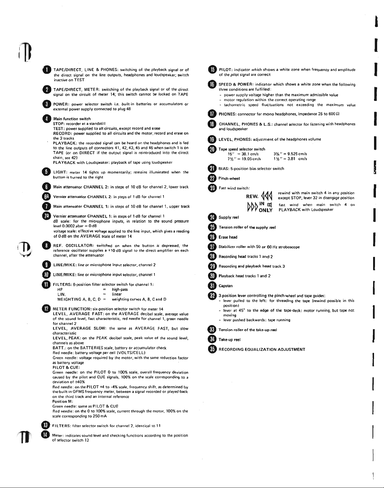
• TAPE/DIRECT, LINE&PHONES: switching of the playback signal o~ of
the direct signal on the line outputs, headphones and loudspeaker; switch
inactive on TEST
• TAPE/DIRECT, METER: switching of the playback signal or of the direct
signal on the circuit of rIleter 14; this switch cannot be locked on TAPE
• POWER: power selector switch i.e. built-in batteries or accumulators or
external power supply connected to plug 48
• Main function switch
STOP: recorder at • standstill
TEST: power sopplied to all circuits, except record and erase
RECORD: power supplied to all circuits and the motor; record and erase on
the 3 tracks
PLAYBACK: the recorded signal can be heard on the headphones and is fed
to the line outputs of connectors 41, 42,43,45 and 46 when switch 1 is on
TAPE (or on DIRECT if the output signal is reintroduced into the direct
chain. see 42)
PLA YBACK with Loudspeaker: playback of tape using loudspeaker
LIGHT; meter 14 lights up momentarily: remains illuminated when the
button is turned to the right
•
o
Main attenuator CHANNEL 2: in steps of 10 dB for channel 2,Iower track
• Vernier attenuator CHANNE L 2; in steps of 1dB for channel 1
• Main attenuator CHANN.E L 1: in steps of 10 dB for channel I, upper track
• Vernier attenuator CHANNE L 1: in steps of 1 dB for channel 1
dB scale: for the microphone inputs, in relation to the sound pressure
level 0.OOO2pbar=0 dB
voltage scale; effective voltage applied to the line input, which gives a reading
of OdB on the AVERAGE scale of meter 14
REF. OSCILLATOR: switched on when the button is depressed, the
reference oscillator supplies a +10 dB signal to the direct amplifier on each
channel, after the attenuator
•
LINE/MIKE: line or microphone input selector, channel 2
LINE/MIKE: line or microphone input selector, channell
•
FI LTERS: 6-position filter selector switch for channell:
•
HP high·pass
L1N. linear
•
WE IGHTING A, B, C, D weighting curves A, B, C and D
METER FUNCTION: six-position selector switch for meter 14
lEVEL. AVERAGE FAST: on the AVERAGE decibel scale, average value
of the sound level, fast characteristic, red needle for channel I, green needle
for channel 2
lEVEL. AVERAGE SLOW; the same as AVERAGE FAST, but slow
characteristic
LEVEL, PEAK: on the PEAK decibel scale, peak value of the sound level,
channels as above
BATT.: on the BATTERIES scale, battery or accumulator check
Red needle: battery voltage per cell (VOLTS/CELL)
Green needle: voltage required by the motor, with the same reduction factor
as battery voltage
PILOT8o CUE:
Green needle: on the PILOT 0 to 100% scale, overall frequency deviation
caused by the pilot and CUE signals, 100% on the scale corresponding to a
deviation of ±40%
Red needle: on the PILOT +4 to -4% scale, frequency shift, as determined by
the built-in OFMS frequency meter, between a signal recorded or played back
on the third track and an internal reference
Position M:
Green needle: same as PILOT&CUE
Red needle: on the 0 to 100% scale, current through the motor, 100% on the
scale corresponding to 250 mA
Fll TERS: filter selector switch for channel 2. identical to II
CD
Meter: indicates sound level and checking functions according to the position
of selector switch 12
•
• PILOT: indicator which shows a white lone when frequency and amplitude
of the pilot signal are correct
SPEED&POWER: indicator which shows a white lone when the following
three conditions are fulfilled:
- power supply voltage higher than the maximum admissible value
- motor regulation within the correct operating range
tachometric speed fluctuations not exceedinq the maximum value
«I»
PHONES: connector for mono headphones, impedance 25 to 600n
• CHANNEL, PHONES&L.S.: channel selector for listening with headphones
and loudspeaker
• LEVEL, PHONES: adjustment of the headphones volume
• Tape speed selector switch
• BIAS: 5'position bias selector switch
• Pinch-wheel
IS"=38.1 cmls
7'/,"
=
19.05cm/s
6)Fast wind switch:
REW.
• Supply reel
• Tension roller of the supplV reel
• Erase head
•• Stabilizer roller with 50 or 60 Hz stroboscope
• Recording head tracks 1 and 2
e.
Recording and playback head track 3
•• Playback head tracks 1 and 2
CD
Capstan
• 3'position lever controlling the pinch-wheel and tape guicles:
. - lever pulled to the left: for threading the tape (rewind possible in this
position)
- lever at 45° to the edge of the tape-deck: motor running, but tape not
moving
- lever pushed backwards: tape running
•• Tension roller of the take-up reel
• Take·up reel
3% .•=9.525 cm/s
1
'h"
=
3.81 ·cm/s
rewind with main switch 4 in any position
except STOP, lever 32 in disengage position
fast wind when main switch 4 on
PLAYBACK with Loudspeaker
6)RECORDING EOUALIZA TION ADJUSTMENT
I
I
I
I
I
I
I
I
I
I
I
I
I
I
Page 3
L-J
l-j
I
[ J
I
~]
[I~
~J
[[=
~~
.--
.L
J
]
J
J
]
Direct analysis of sound signals
Used solely as an amplifier the NAGRA IV-SJ is a
precision sound level meter, which operates with
any calibrated microphone cartridge. The sound
pressure measurements must be taken in relation to
the
0
dB reference level, which corresponds to a
pressure of 0.0002 ubar, i.e. 20
This level coincides in practice with the audibility
threshold of the human ear at
quency, the sound level can be expressed in phones,
the phones value being equal to the dB value read
in relation to the 0.0002 /-Ibarreference.
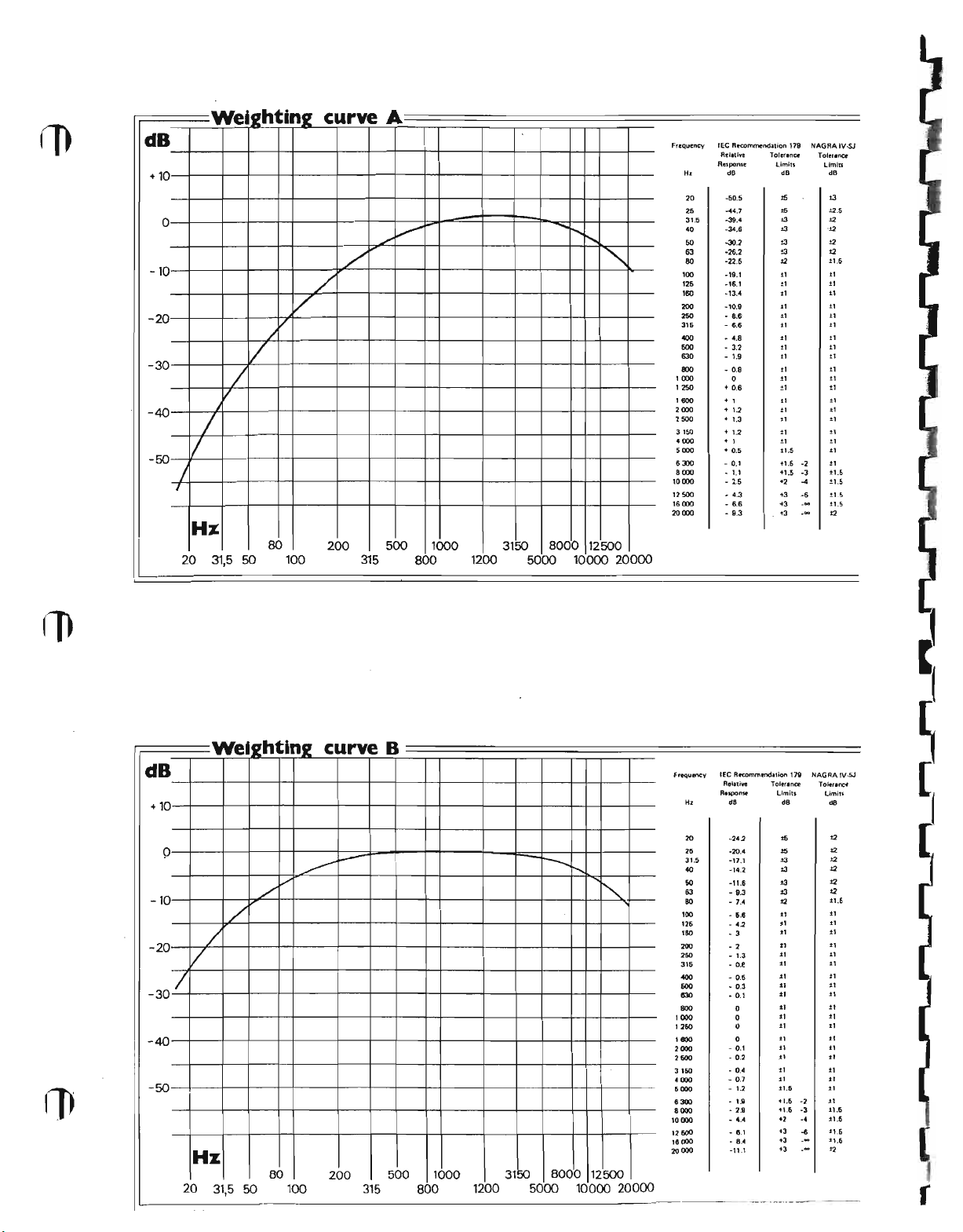
'.The frequency response of the human ear is not
linear and depends very much on the sound level; a
sound level meter must therefore include weighting
filters which modify the values measured in accordance with certain criteria, so that they can be
interpreted in relation to the subjective impression
felt by the human ear. There are three standard
weighting curves, A, Band C. Curve A is used for
low and medium sound levels, which are the subject of most analyses; curves Band C relate to
higher levels. Curve D relates to contour-lines of·
perceived noisiness, in particular with noise pro-
duced by aviation: this weighting is used for the
measurement of sounds which cause annoyance
in general. Curves A, B, G and D are shown after
the specifications.
The sound level measured is shown on a dual
galvanometer. with one needle per channel. Its
measuring circuit determines the average value of
the signal on RMS and its peak value on
PEAK, with different dynamic characteristics in
relation to the integration time. On RMS
FAST integration time is 200 ms: a signal at
lasting 200 ms gives a reading
which would correspond to the steady signal. On
RMS SLOW, integration time is 500 ms and
a signal lasting 500 ms gives a reading 4 dB below
that which would correspond to the steady signal.
These two integration times are in accordance with
J.lN/m2or 20 J.lPa.
1 kHz; at this fre-
1 kHz
1 dB lower than that
INSTRUCTION MANUAL
I
the GEl standard 179 for
meters. Naturally, any signal which is shorter than
the integration time will be shown below its real
value. For analysis of pulse signals or strong
transients a more useful reading is obtained on
PEAK, i.e. peak value with an integration time of
5
only
because it causes visual fatigue: in order to overcome this disadvantage the measuring circuit holds
the signal for about one second, thereby increasing
the fall time of the needle.
Recording and playback of the sound signals
In all cases where direct. measurement is not
sufficient for studying the signals picked up by the
microphone, these signals can be recorded on magnetic tape and analyzed later in the laboratory.
While the two tracks used for direct recording are
in use, the third track
synchronization, a commentary, or a measuringsignal from D.C. up to 4 kHz. The three tracks
thus store signals in fully-synchronized form, which
is an important factor for analysis.
However, this storage is restricted to some extent
due to the limitations of present magnetic tapes.
These limitations concern the following charac-
teristics in particular:
the response curve
Attenuation at the upper and lower extremes of
the spectrum depends on the speed used. Very low
frequency signals, which are difficult to play back
with a small reproduce head, should be analyzed
by frequency transposition.
distortion
This increases very rapidly as soon as the maximum
recording level is exceeded, and tape saturation
occurs, generating harmonic frequencies (in
ticular 2nd and 3rd harmonics), which falsify the
analysis of the signals.
ms. This very fast reading cannot be used
Measurements
precrsion
C'IO
record F M signals for
sound level
par
Page 4
I
crosstalk
The juxtaposition of the two channels inside the
recording head and the playback head produces
crosstalk. This is the ratio, at a playback amplifier
output. between the wanted signal and the unwanted signal from the other channel. Crosstalk
increases at high frequencies.
The maximum peak level, which corresponds to a
tape flux of 32 mM/mm, is reached when the
measuring instrument shows
RMS scale and +20 dB on the PEAK scale.
These two values are given in relation to the sound
·pressure reference level 0 dB
0.0002J.1bar.
On RMS the integration time of the
measuring circuit is long enough not to indicate
short pulses at their exact value and risk exceeding
the maximum recording level, thereby saturating
the tape. That is why, on RMS , the maxi-
+
10
mum level is given at
the signals with strong pulse content saturating the
tape too Quickly.
In all cases where the nature of a signal is not
obvious it should be recorded with the measuring
circuit on PEAK, which is the only way to make
the peak value of very short pulses visible and to
avoid their exceeding the maximum recording level.
Frequency transposition
Playback speed may be different from recording
speed: this produces a frequency transposition of
the signals recorded within the ratio of these two
speeds. Since the response curve in the low frequencies is limited to
possible, if the tape transport speed is ten times
faster on playback than on recording, to play back
frequencies which are ten times. lower. Thus, a
2.5 Hz signal recorded at 1.5 ips will have a fre·
quency of
(transposition
conventional equipment. In the same way, the
time needed to analyze signals which vary very
slowly is reduced in the same ratio by this process.
Conversely. it is possible to analyze in more detail
a signal which varies rapidly by playing it back
more slowly than it was recorded. However, in
both cases, care must be taken that the transposition does not alter the signals in any way, taking
into account the limitations of the frequency res-
ponse at the speeds used.
25 Hz if it is played back at 15 ips
1: 1
0), and can be analyzed easily by
dB: the10dB lead avoids
25 Hz on playback only, it is
+10 dB on the
=
20 pPa or
I
I
I
I
I
I
I
I
I
I
Page 5
I
I
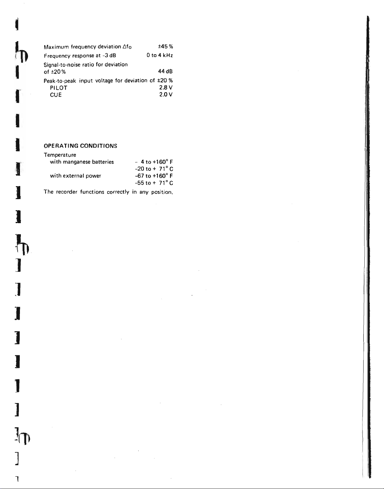
Maximum frequency deviation t>fo
Frequency response at
Signal-to-noise ratio for deviation
of ±20%
Peak-to-peak input voltage for deviation of ±20
PILOT
CUE 2.0 V
-3 dB
o
to 4 kHz
±45%
44dB
2_8 V
%
I
I
I
I
]
]
J
OPERATING CONDITIONS
Temperature
with manganese batteries
with external power
The recorder functions correctly in any position.
- 4to+160°F
-20to+ 71°C
-67 to +160
-55 to
+
0
71 °C
F
]
I
)
]
1
Page 6
dB
+10
-10
-20
-30
-40
-50
Wei21
ht'
0
.I
/
I
/
/
/
J
I
In2
V
curve
/
A
Ffequency lEe Recommendation 179
/
./
./
.•...•.
!'-..
<,
10000
'2500
'6000 - 6.6 +3
20000
Rt'I.tI~
Respome
H,
20
25
31,5
40
SO
63
80
'00
'25
'60
200
250
3'5
"""
500
630
800
1000
1250
1600 + I
2000
2500
3150
4000 + 1
5000
6300
8000
dB
·50.5
-" •. 7
-39.4
-34.6
-30.2
-26.2
-22.5
-'9.1
-16.1
-13.4
-10.9
- •. 6
- 6.6
- ".8
- 3.2
- 1.9
- O.S
.•. 0.6
+ 1.2
.• 1.3
+ 1.2
-+
- 0.1
-1.1
- 2.5
- 4.3
- 9.3
0
0.5
Tolrnn~
limitl
dB dB
,.
••
oJ
oJ
oJ
±3
12
11
t'
.,
.,
11 11
11
11
±,
.,
.,
±1
"
"
.,
"
et
et
!.1.S
+1.5
+1.5
+2
+3 -6
+3
N"GRAIV.sJ
-2
-3
..
_M
_M
Toler.nee
lImln
!3
:!:2.S
.,
.
.,
.,
t2
11,5
t,
11
11
l'
.,
t,
11
11
11
11
11
et
11
.,
.,
11
11
.,
%1.5
11.5
11.5
1:1.5
t2
Hz
20
80
50 100 315
31,5
200
500
1000 3150 8000 12500
800
1200
5000 10000
20000
dB
+10
-10
-20
-30/
-40
-50
Wet21 n2
hti
0
./
/
/
V
20
Hz
31,5 50
80
./
100
»>
curve
~
200
B
500 1000
315
800
-r---.
.•...•.
8000
3150
12500
1200 5000 10000
<,
20000
frequency
H,
20
25
31.5
40 -14.2
SO
63
eo
100
120
ISO
200
260
316
"""
600
830
800
, GOD
1260
1e00
2000
2500
3160
4000
6000
8_
8000
10000
12500
18000
20000
tEe Aecommmdation 1N
A.I.live
Response
Toleranoe
limits
d8
·242
-20.4
-17.1
-u.s
- 9.3
- 7.4
- 5.e
- 42
- 3
- 2
- 1.3
- D.e
- 0.5
- 0.3
- 0.1
- O.t
- D.2
- 0."
- 0.7
- 12
o
-a
- 4."
- 6.1
- 8.4
-11.1
_.-._--------_.
0
0
0
0
1.8
dB dB
••
15
13 12
03
03
03
12
., .,
.,
"
.,
11
.,
11 11
.,
.,
tI
at
.,
.,
"
.,
11 11
"
.11.5
.1.5
1-t.fI
'2
+3
+3
+3
NAGAAIV·SJ
-2
-3
-4
-6
--
--
To~nlnce
limite
12
12
12
t2
12
:1:1.6
11
"
et
"
11
.,
11
11
11
.,
.,
11
11
11
11
.,
.11.5
i1.6
11.6
il,6
"
---
r
Page 7
t
ln
I
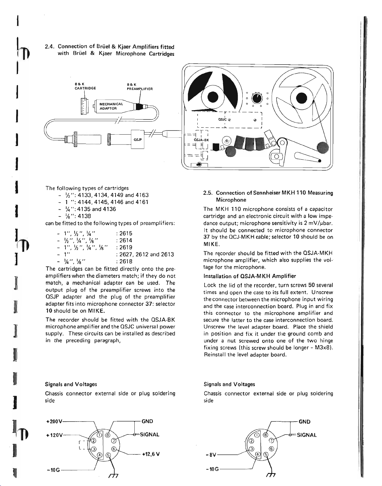
2.4. Connection of Brliel&Kjaer Amplifiers fitted
with Brliel
&
Kjaer Microphone Cartridges
I
I
I
J
I
I
I
J
]
I
]
I
B&K
CARTRIDGE
~
The following types of cartridges
- 'h";4133,4134,4149and4163
- 1 ";4144,4145,4146and4161
- 1,4";
- 1/8";
can be fitted to the following types of preamplifiers:
- 1",
- '12
- 1",
- 1" : 2627, 2612 and 2613
- 1,4",
The cartridges can be fitted directly onto the preamplifiers when the diameters match; if they do not
match, a mechanical adapter can be used. The
output plug of the preamplifier screws into the
OSJP adapter and the plug of the preamplifier
adapter fits into microphone connector
10 should be on MI KE.
The recorder should be fitted with the QSJA-BK
microphone amplifier and the QSJC universal power
supply. These circuits can be installed as described
in the preceding paragraph,
4135 and 4136
4 138
1/2",
1,4" :
",1,4 ",
1/8" :
'12",
1,4",
1/8" :
%" : 2618
B&K
PREAMPLIFIER
261 5
2614
2619
37:
selector
---1
QJ
I
L --l:o... .1
~T-'
=-=1
I
I
QSJA-BK
I
I
='iJJ
==[J
~
2.5. Connection of Sennheiser MKH 110 Measuring
Microphone
The MKH 110 microphone consists of a capacitor
cartridge and an electronic circuit with a low impedance output; microphone sensitivity is 2 mV
It should be connected to microphone connector
37
by the QCJ-MKH cable; selector 10 should be on
MIKE_
The recorder should be fitted with the QSJA-MKH
microphone amplifier, which also supplies the vol-·
tage for the microphone.
Installation of aSJA-MKH Amplifier
Lock the lid of the recorder, turn screws 50 several
times and open the case to its full extent. Unscrew
the connector between the microphone input wiring
and the case interconnection board. Plug in and fix
this connector to the microphone amplifier and
secure the latter to the case interconnection board.
Unscrew the level adapter board. Place the shield
in position and fix it under tile ground comb and
under a nut screwed onto one of the two hinge
fixing screws (this screw should be longer - M3x8).
Reinstall the level adapter board.
IMbar.
I
J
.J
,
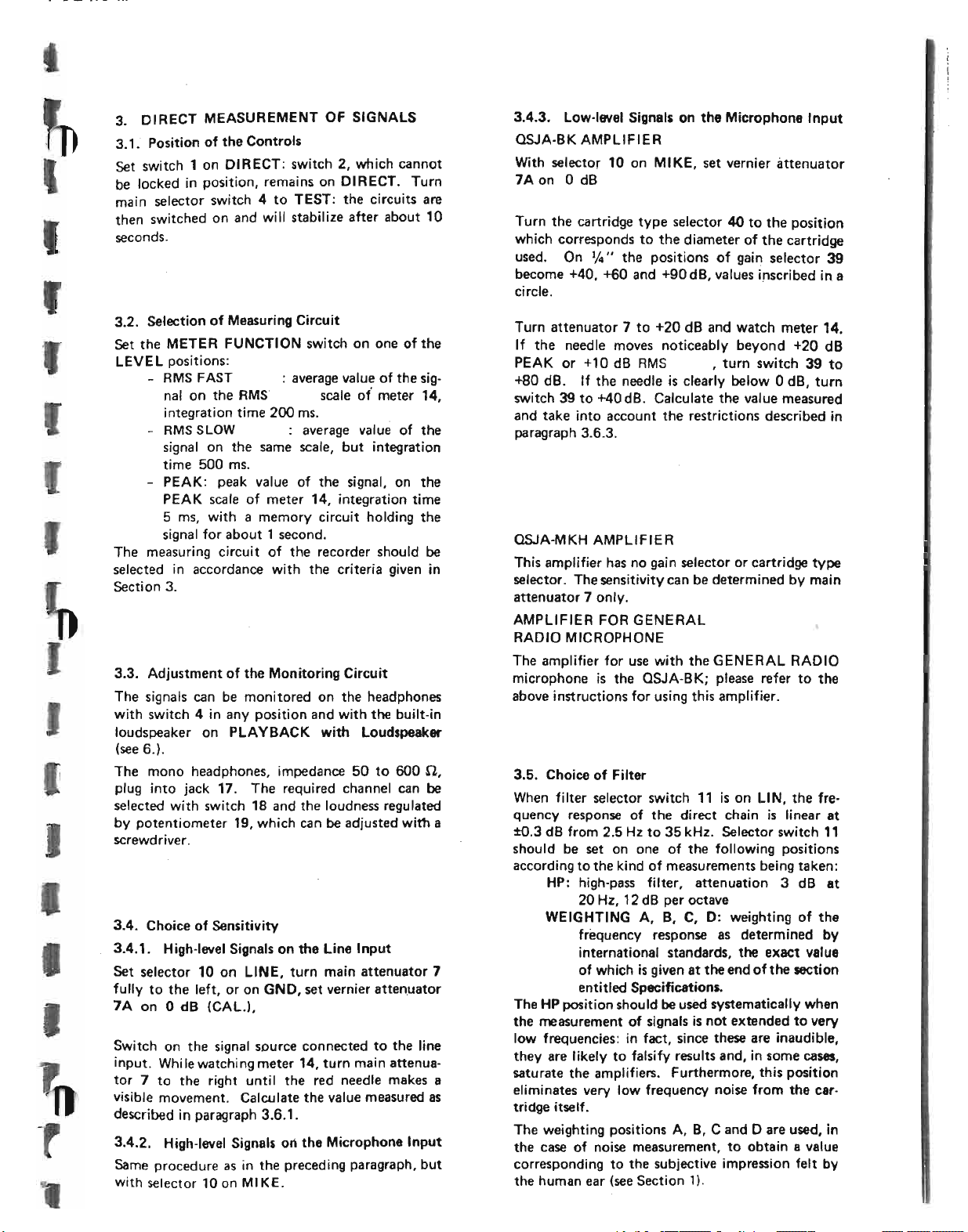
Signals and Voltages
Chassis connector external side or plug soldering
side
+200Y
+120V
r -
L_
-10G
,-----r-GND
+12,6V
Signals and Voltages
Chassis connector external side or plug soldering
side
~--..,.-- GNO
SIGNAL
-8Y------
-10G----~
Page 8
,
,
I
,
3. DIRECT MEASUREMENT OF SIGNALS
3.1.
Position of the Controls
Set switch 1 on DIRECT: switch 2, which cannot
be locked in position, remains on DIRECT. Turn
main selector switch 4 to TEST: the circuits are
then switched on and will stabilize after about 10
seconds.
3.4.3. Low·level Signals on the Microphone Input
QSJA-BK AMPLIFIER
With selector
7A
on0dB
Turn the cartridge type selector 40 to the position
which corresponds to the diameter of the cartridge
used. On
become +40. +60 and +90dB, values inscribed in a
circle.
10
on MIKE, set vernier attenuator
1f.t ••
the positions of gain selector 39
3.2. Selection of Measuring Circuit
Set the METER FUNCTION switch on one of the
LEVEL positions:
- RMS FAST : average valu~ of the sig·
nal on the RMS' scale of meter 14,
integration time 200 ms.
I
I
I
- RMS SLOW : average value of the
signal on the same scale, but integration
time 500 ms.
- PEAK: peak value of the signal, on the
PEAK scale of meter 14, integration time
5 ms, with a memory circuit holding the
signal for about
The measuring circuit of the recorder should be
selected in accordance with the criteria given in
Section
3.3. Adjustment of the Monitoring Circuit
The signals can be monitored on the headphones
with switch
loudspeaker on PLAYBACK with Loudspeaker
(see 6.).
The mono headphones, impedance 50 to 600
plug into jack 17. The required channel can be
selected with switch
by potentiometer
screwdriver.
3.
4
in any position and with the built-in
1 second.
18
and the loudness regulated
19,
which can be adjusted with a
n.
I
3.4.
Choice of Sensitivity
3.4.1.
I
Set selector 10 on LINE, turn main attenuator 7
fully to the left, or on GND, set vernier attenuator
7A on 0 dB (CAL.),
High·level Signals on the Line Input
I
Switch on the signal source connected to the line
input. While watching meter 14, turn main attenuator 7 to the right until the red needle makes a
visible movement. Calculate the value measured as
described in paragraph 3.6.1.
3.4.2. High-level Signals on the Microphone Input
Same procedure as in the preceding paragraph, but
with selector
10
on MIKE.
Turn attenuator
If the needle moves noticeably beyond +20 dB
PEAK or +10 dB RMS , turn switch 39 to
+80 dB. If the needle is clearly below 0 dB, turn
switch 39 to +40 dB. Calculate the value measured
and take into account the restrictions described in
paragraph
QSJA-MKH AMPLIFIER
This amplifier has no gain selector or cartridge type
selector. The sensitivity can be determined by main
attenuator
AMPLIFIER FOR GENERAL
RADIO MICROPHONE
The amplifier for use with the GENERAL RADIO
microphone is the QSJA-BK; please refer to the
above instructions for using this amplifier.
3.5. Choice of Filter
When filter selector switch 11 is on LlN, the
quency response of the direct chainislinear at
:to.3 dB from 2.5 Hz to 35 kHz. Selector switch
should be set on one of the following positions
according to the kind of measurements being taken:
HP: high-pass filter, attenuation
WEIGHTING A, B, C, D: weighting of the
The HP position should be used systematically when
the measurement of signals is not extended to very
low frequencies: in fact, since these are inaudible,
they are likely to falsify results and, in some cases,
saturate the amplifiers. Furthermore, this position
eliminates very low frequency noise from the cartridge itself.
The weighting positions A, B, C and D are used, in
the case of noise measurement, to obtain a value
corresponding to the subjective impression felt by
the human ear (see Section 1).
7 to +20 dB and watch meter 14.
3.6.3.
7
only.
fre-
3
dB at
20 Hz, 12 dB per octave
frequency response as determined by
international standards, the exact value
of which is given at the end of the section
entitled Specifications.
11
Page 9
/
I-I
i-
II
J
I-
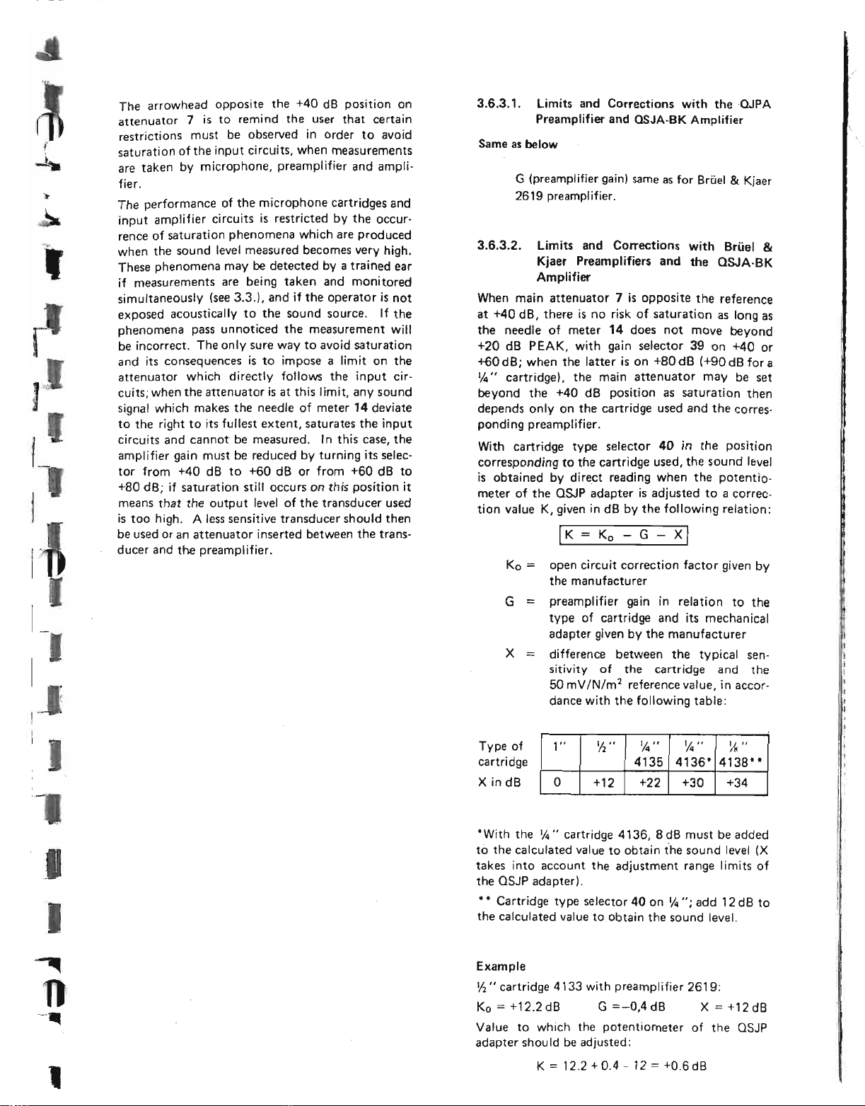
The arrowhead opposite the +40 dB position on
attenuator
restrictions must be observed in order to avoid
saturation of the input circuits, when measurements
are taken by microphone, preamplifier and ampli-
fier.
The performance of the microphone cartridges and
input amplifier circuits is restricted by the occur-
rence of saturation phenomena which are produced
when the sound level measured becomes very high.
These phenomena may be detected by a trained ear
if measurements are being taken and monitored
simultaneously (see
exposed acoustically to the sound source. If the
phenomena pass unnoticed the measurement will
be incorrect. The only sure way to avoid saturation
and its consequences is to impose a limit on the
attenuator which directly follows the input circuits; when the attenuator is at this limit, any sound
signal which makes the needle of meter
to the right to its fullest extent, saturates the input
circuits and cannot be measured. In this case, the
amplifier gain must be reduced by turning its selec-
tor from +40 dB to +60 dB or from +60 dB to
+80 dB; if saturation still occurs on this position it
means that the output level of the transducer used
is too high. A less sensitive transducer should then
be used or an attenuator inserted between the transducer and the preamplifier.
7
is to remind the user that certain
3.3.).
and if the operator is not
14
deviate
3.6.3.1. Limits and Corrections with theOJPA
Preamplifier and
Same as below
G (preamplifier gain) same as for Brtiel
2619 preamplifier.
3.6.3.2.
When main attenuator
at +40 dB, there is no risk of saturation as long as
the needle of meter
+20 dB PEAK, with gain selector 39 on +40 or
+GOdB; when the latter is on +80dB (+90 dB fora
~" cartridge), the main attenuator may be set
beyond the +40 dB position as saturation then
depends only on the cartridge used and the corresponding preamplifier.
With cartridge type selector
corresponding to the cartridge used, the sound level
is obtained by direct reading when the potentiometer of the QSJP adapter is adjusted to a correction value K, given in dB by the following relation:
limits and Corrections with Brfiel
Kjaer Preamplifiers and the QSJA-BK
Amplifier
I
K=Ko - G - X
Ko==open circuit correction factor given by
the manufacturer
G
==
preamplifier gain in relation to the
type of cartridge and its mechanical
adapter given by the manufacturer
X difference between the typical sen-
sitivity of the cartridge and the
50 mV/N/m1reference value, in accor-
dance with the following table:
OSJA-BK Amplifier
7
is opposite the reference
14
does not move beyond
40
in the position
I
&
Kjaer
&
J
I
,
Type of
cartridge
X
in dB
*With the 1/4" cartridge 4136, 8 dB must be added
to the calculated value to obtain the sound level
takes into account the adjustment range limits of
the QSJP adapter).
**
Cartridge type selector 40 on 1/4 ": add 12 dB to
the calculated value to obtain the sound level.
Example
Ih"
cartridge 4133 with preamplifier 2619:
Ko=+12.2dB G=-O,4dB X=+12dB
Value to which the potentiometer of the QSJP
adapter shou Id be adjusted:
1"
K
=
'12 "
+12
0
12.2+0.4 - 12=+O.6d8
1,4 ••
4135 4136*
+22
'14"
+30
I/~"
4138"
+34
(X
Page 10
t
p"-
-l
I
I
I
I
I
I
4. RECORDING OF SIGNALS
4.1. Choice of Tape
It is essential to use the type of magnetic tape for
which the recorder was adjusted at the factory; it is
only in this way that the values indicated in the
technical specifications {Section 2) can be obtained.
It is possible to use another type of tape by reo
adjusting the bias, equalization and recording level
. The performance obtained may
differ from the values shown in the test report
issued with each recorder; it is necessary to check
the results obtained with a new tape before using
the recorder for taking accurate measurements.
The positions of bias selector switch 21 correspond
to steps of 10%.
The length of the recording to be made is also a
determining factor in choosing the tape speed.
Place speed selector 20 on the position corresponding to the wanted speed; the speed can be switched
while the tape is running without damaging the
recorder.
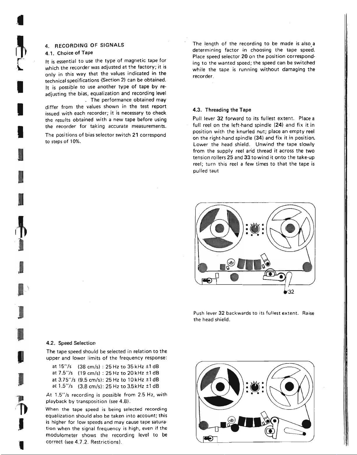
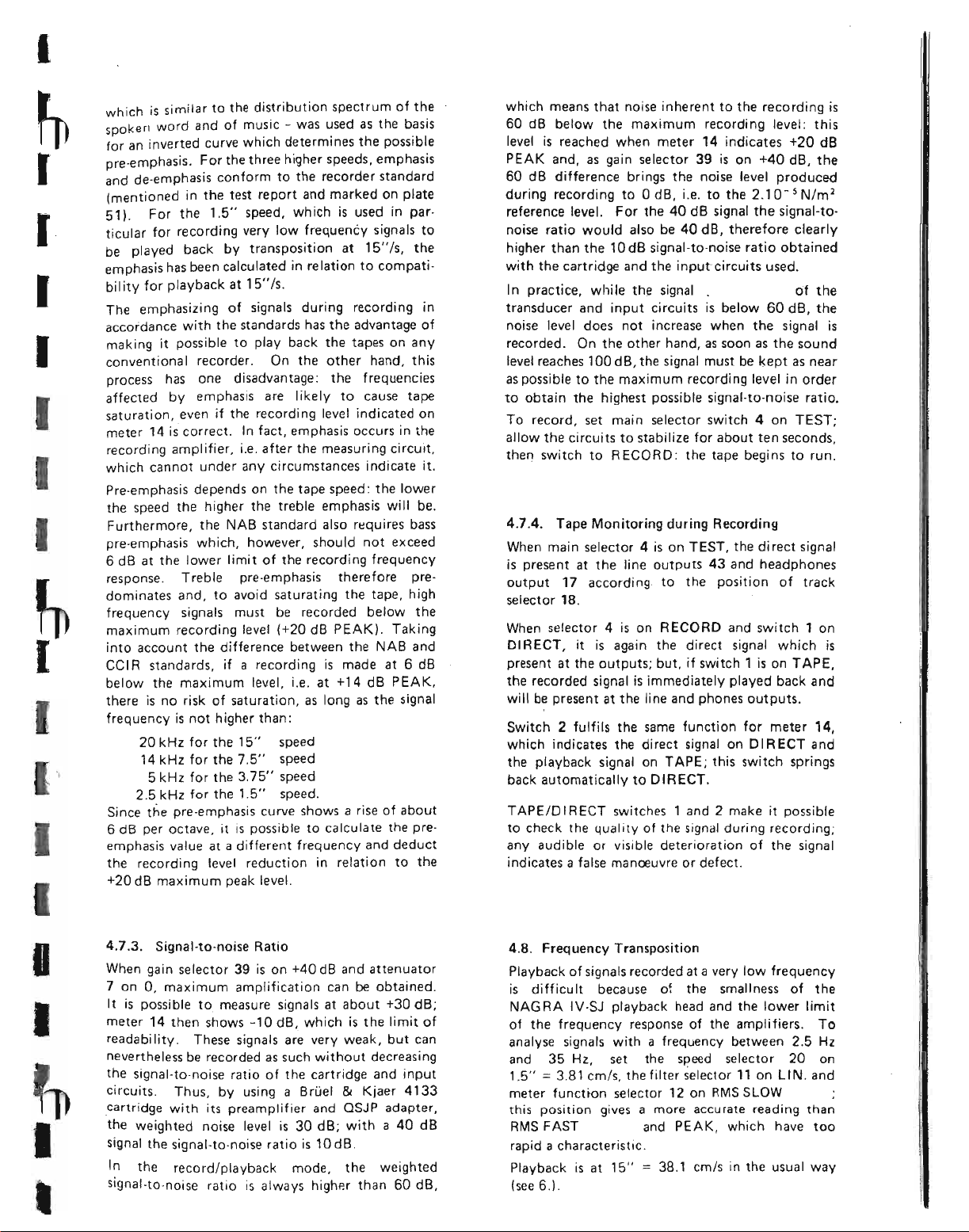
4.3. Threading the Tape
Pull lever 32 forward to its fullest extent. Place a
full reel on the left-hand spindle (24) and fix it in
position with the knurled nut; place an empty reel
on the right-hand spindle (34) and fix it in position.
Lower the head shield. Unwind the tape slowly
from the supply reel arid thread it across the two
tension rollers 25 and 33 to wind it onto the take-up
reel; turn this reel a few times to that the tape is
pulled taut
J
I
J
,
4.2. Speed Selection
The tape speed should be selected in relation to the
upper and lower limits of the frequency response:
at 15"/s (38 cm/s) : 25 Hz to 35 kHz ±1 dB
at 7.5"/s (19 cm/s) : 25 Hz to 20 kHz ±1 dB
at 3.75"/s (9.5 cm/s): 25 Hz to 10kHz ±1 dB
±
at 1.5"/5 (3.8 crn/sl: 25 Hz to 3.5 kHz
At 1.5"/s recording is possible from 2.5 Hz, with
playback by transposition (see 4.8).
When the tape speed is being selected recording
equalization should also be taken into account; this
is higher for low speeds and may cause tape saturation when the signal frequency is high, even if the
modulometer shows the recording level to be
correct (see 4.7.2. Restrictions).
1dB
:w:
••••
o •
Push lever 32 backwards to its fullest extent. Raise
the head shield.
Page 11
I
I
I
I
I
~
I
I
I
which is similar to the distribution spectrum of the
spoken word and of music - was used as the basis
for an inverted curve which determi nes the possible
pre-emphasis. For the three higher speeds, emphasis
and de-emphasis conform to the recorder standard
(mentioned in the test report and marked on plate
51).
For the
I
I
ticular for recording very low frequency signals to
be played back by transposition at
emphasis has been calculated in relation to compatibility for playback at
The emphasizing of signals during recording in
accordance with the standards has the advantage of
making it possible to play back the tapes on any
conventional recorder. On the other hand, this
process has one disadvantage: the frequencies
affected by emphasis are likely to cause tape
saturation, even if the recording level indicated on
meter 14 is correct. In fact, emphasis occurs in the
recording amplifier, i.e. after the measuring circuit,
which cannot under any circumstances indicate it.
Pre-emphasis depends on the tape speed: the lower
the speed the higher the treble emphasis will be.
Furthermore, the NAB standard also requires bass
pre-emphasis which, however, should not exceed
6
dB at the lower limit of the recording frequency
response. Treble pre-emphasis therefore predominates and, to avoid saturating the tape, high
frequency signals must be recorded below the
maximum recording level (+20 dB PEAK). Taking
into account the difference between the NAB and
cel R standards, ifarecording is made at 6 dB
below the maximum level, i.e. at +14 dB PEAK,
there is no risk of saturation, as long as the signal
frequency is not higher than:
20
kHz for the
14 kHz for the 7.5" speed
5 kHz for the 3.75" speed
2.5
kHz for the
Since the pre-emphasis curve shows a rise of about
6 dB per octave. it is possible to calculate the pre-
emphasis value at a different frequency and deduct
the recording level reduction in relation to the
+20 dB maximum peak level.
1.5"
speed, which is used in par-
15"/5.
15"
speed
1.5"
speed.
15"
Is,
the
which means that noise inherent to the recording is
60 dB below the maximum recording level: this
level is reached when meter 14 indicates +20 dB
PEAK and, as gain selector 39 is on +40 dB, the
60
dB difference brings the noise level produced
during recording to 0 dB, i.e. to the 2.10- 5 Nlm
reference level. For the 40 dB signal the signal-tonoise ratio would also be 40 dB, therefore clearly
higher than the 10 dB signal-to-noise ratio obtained
with the cartridge and the input circuits used.
I
n practice, whi Ie the signal . of the
transducer and input circuits is below
noise level does not increase when the signal is
recorded. On the other hand, as soon as the sound
level reaches 100 dB, the signal must be kept as near
as possible to the maximum recording level in order
to obtain the highest possible signal·to-noise ratio.
To record, set main selector switch4on TEST;
allow the circuits to stabilize for about t~n seconds,
then
switch to RECORD: the tape begins to run.
4.7.4. Tape Monitoring during Recording
When main selector4is on TEST, the di rect signal
is present at the line outputs 43 and headphones
output
selector
When selector
DIRECT, it is again the direct signal which is
present at the outputs; but, if switch 1 is on TAPE,
the recorded signal is immediately played back and
will be present at the line and phones outputs.
Switch 2 fulfils the same function for meter 14,
which indicates the direct signal on DIRECT and
the playback signal on TAPE; this switch springs
back automatically to DIRECT.
TAPE/D IR ECT switches 1 and 2 make it possible
to check the quality of the signal during recording;
any audible or visible deterioration of the signal
indicates a false manoeuvre or defect.
17
according to the position of track
18.
4
is on RECORD and switch1on
60
dB, the
2
I
I
I
~
I
,
4.7.3.
When gain selector 39 is on +40 dB and attenuator
7 on 0, maximum amplification can be obtained.
It
meter 14 then shows -10 dB, which is the limit of
readability. These signals are very weak, but can
nevertheless be recorded as such without decreasing
the signal·to-noise ratio of the cartridge and input
circuits. Thus, by using a BrLiel&Kjaer 4133
cartridge with its preamplifier and QSJP adapter,
the weighted noise level is 30 dB; with a 40 dB
signal the signal-to-noise ratio is 1OdB.
signal-to-noise ratio is always higher than 60 dB,
Signal·to·noise Ratio
is possible to measure signals at about +30 dB;
In the record/playback mode, the weighted
4.8. Frequency Transposition
Playback of signals recorded at a very low frequency
is difficult because of the smallness of the
NAG RA
of the frequency response of the amplifiers. To
analyse signals withafrequency between
and 35 Hz, set the speed selector 20 on
1.5"=3.81
meter function selector 12 on RMS SLOW
this position gives a more accurate reading than
RMS FAST and PEAK, which have too
rapid a characteristic.
Playback is at
(see 6.).
IV -SJ
playback head and the lower limit
crn/s, the filter selector
15"=38.1
em/s
in the usual way
11
on LI N. and
2.5
Hz
Page 12
6.3. Interpretation of the Recorded Signals
It is necessary to fix a reference during recording
so that, when the recorded signals are analysed,
the exact value of the sound level can be
determined.
I
6.3.1. Written or Recorded Reference
I
I
I
I
I
I
I
I
I
I
Before recording is begun, the position of the microphone amplifier gain selector
attenuator
or7A) should be noted on the recording data sheet,
or dictated on the third track using the QSCM
microphone. On playback, with METER switch 2
and LINE
will indicate the same value as during recording
and the output voltage will be in proportion to the
meter reading. If the tape is analysed on the recorder itself, it is sufficient to add, in the usual way,
the value shown by the meter to the attenuator
and gain selector readings, which were taken during
recording. If analysis is done with the recorder
connected to exter.nal analysing equipment, the out·
put voltage can be compared with the 0 dB
references given in paragraph 6.1., thus making it
possible to determine the fraction of the sound
level given by the meter reading and to calibrate
the equipment. Finally, if analysis is done on a
recorder other than the NAGRA IV-SJ, the same
fraction of the sound level will be deducted from
the tape flux, the 0 dB meter reading corresponding
to 32 nWb/m on the tape.
In all cases, the position of the attenuators and that
of the microphone amplifier gain selector must be
known in order to determine the sound level at the
time of recording.
The accuracy of the meter reading on playback
depends on the quality of the tape used; even if it
is the kind of tape for which the recorder was
adjusted, the difference between the reading on
TAPE and on DIRECT may reach 2dB.
6.3.2. Recorded Internal Reference Signal
This method is more rapid and more accurate, but
still requires written notes or commentary on the
third track; it can be used to eliminate the playback
level inaccuracy due to the dispersion of the charac-
teristics of a tape of the same type. The reference
·generator built into the recorder applies a calibration signal to the output of the direct amplifier,
without passing through the attenuators. When the
microphone amplifier gain selector and the
attenuators are adjusted to obtain a correct recording, the reference signal must be recorded at the
beginning of the tape and note taken of the sound
level to which it corresponds. This signal will be
used on playback for finding the sound level again
by conversion.
(6 or 7) and the vernier attenuator (6A
&
PHONES switch 1 on TAPE, meter 14
(38 or 39), the main
Example: the gain selector of the microphone
amplifier is on +60 dB, the main attenuator on
+30 dB and the vernier attenuator on 0 dB; record
the reference signal: the meter shows +10 dB; the
reference signal therefore corresponds to a sound
=
level of 60 + 30 + 10
the equipment will be calibrated at +100 dB when
the reference signal is played back.
6.3.3. Recorded External Signal Reference
An acoustic signal with a known sound level can be
used as a reference during recording. The B
pistonphone supplies a 250 Hz signal at 124 dB
±O.2
dB, and the B &Kcalibrator a 1 kHz signal at
94 dB ±0.3 dB.
Insert the microphone into the sound source and
check the calibration of the recorder by trying to
obtain a deviation on the meter between 0 and
+10 dB, then record this signal noting the position
of the microphone amplifier gain selector and that
of the attenuators. On playback this signal will
rep resent a reference at +124 or +94 dB.
If the signal to be analysed is at a very different
sound level, after calibration has been checked, the
gain selector and the attenuators must be reset in a
position which allows correct recording, and the
positions noted again. On playback the level of the
recorded reference signal no longer corresponds to
+124 or +94 dB; it should be calculated by adding
the difference in decibels between the first and
second reading to these values.
Example: the gain selector is on +80 dB, the main
attenuator on +40 dB and the vernier attenuator
on 0 dB; using the pistonphone, the reference signal
will be indicated at +4 dB (80 + 40 + 0 + 4
+124 dB) and recorded. The signal to be ana lysed
must be recorded with the gain selector on +60 dB,
the main attenuator on +30 dB, the vernier
attenuator on 0 dB, and it gives a reading of +10 dB;
its level is therefore 60 + 30 + 0 + 10=+100dB.
Attenuation indication for the reference signal:
80 + 40 + 0=120 dB
Attenuation indication for the signal to be analysed:
60 + 30 + 0
Difference: 90 - 120=-30 dB
Apparent level of the reference signal on playback:
124 - 30=+94 dB
=
+100 dB. During analysis
&
90 dB
K
=
Page 13
I
I
I
I
I
I
I
I
INSTRUCTION MANUAL
~
I
I
Batteries and Accumulators
I
4
I
The NAGRA IV-SJ or IV-SJS has space for .12
1.5 V cells (nominal voltage). Batteries conforming
I
to CE I (e.g. R20 type) or ASA (e.q. D or L90 type)
standards are suitable; their diameter should not
exceed 1
ween 21
The central electrode is positive and the can
negative, with a few exceptions; polarity is generally
shown byEBandesigns. If the batteries do not fit
securely in the box, the cells can be packed with
cotton wool, which will prevent them from producing unwanted noise while the recorder is in use.
If the batteries are too short and do not produce
the required contact, nickel or bronze (not aluminium) coins can be inserted between the cells. A
mechanical adapter is available for use with NAGRA
recorders; this can be fixed to the contacts when
cells shorter than the minimum length are used
consistently.
1. Power Supply Voltage
New carbon-zinc batteries supply a total voltage of
18 V. The recorder will still function correctly
with 12 V at 15 ips (38 cm/s) and 11 V at the three
low speeds, when it is in perfect condition and wor-
king at a normal temperature. The built-in voltage
stabil izer means that the functioning of the recorder
does not depend on the unstabilized supply voltage,
except during fast wind which is at a speed in
direct proportion to the supply voltage.
2. Danger of Polarity Inversion
A diode connected in parallel on the power supply
will short circuit it if polarity inversion occurs.
The discharge current may overheat the wiring
insulation, which disintegrates and produces cor-
rosive agents. 2,5A fuses inserted in the battery box
5
/
" (33.5 mm) and they should be bet-
16
\132"
(59.5 mm) and 2
breaks the circuit; this fuse should be replaced
j
5/
" (62.5 mm) long.
32
if the recorder still does not work after the cells
have been replaced in the correct order.
3. Check on Supply Voltage and Condition of
the Batteries or Accumulators
Set meter function switch 12 on BATT. and main
switch 4 on RECORD. The red needle of meter 14
shows the unstabilized voltage expressed for one
cell (VOLTS/CELL); the total voltage is obtained
by multiplying this reading by 12. Simultaneously
the green needle indicates the voltage required by
the motor, with the same reduction factor; the
wider the angle between the two needles, the greater
the voltage reserve.
The index at 1.25 V on the scale marks the mini-
mum voltage at which manganese dioxide batteries
should be recharged so that the discharge/recharge
cycle can be repeated several dozen times.
SPEED
signal when the recorder is in operation: it shows a
white segment when voltage and speed are correct,
but turns black as soon as the supply voltage falls
below the minimum admissible value.
4. Operating Conditions
The following data have been extracted from docu-
mentation obtained from various suppliers. The list
of makes quoted here is not exclusive; the manu-
facturers mentioned are those which provide the
most accurate and readily-available information.
KUDELSKI S.A. does not accept any responsibility
for the degree of accuracy of the values indicated.
In general, thr, performance of a battery cell or
accumulator depends largely on the conditions and
length of storage before use. Care should therefore
be taken when suppliers are selected
&
POWER indicator 16 gives a warning
•
Page 14
L
5. Leclanche Standard Batteries (carbon-zinc)
These batteries are light, inexpensive and sold every-
where. Their capacity varies considerably, depend-
ing on how they are used: it is high with low current,
but low with high current and acceptable with an
average current of about 350 mA, if periods of use
are interspersed with rest periods during which the
cells can depolarize (e.g. 4 hours use every 24 hours).
Normally the batteries can be used at temperatures
from 32° F (0° C) to 122
special types can be used at a lower temperature.
If batteries are stored at or below 68
their shelf life should be more than 12 months,
with remaining energy content 75 to 90%. This is
reduced to three months when the storage temperature is "04° F (+40° C). Above 122
batteries deteriorate rapidly. Cold storage produces
excellent results and certain cells retain their full
capacity if deep-frozen.
A carbon-zinc battery is considered to be completely discharged when the voltage at its terminals
falls to 0.9 V with normal current flow.
6. Manganese Dioxide Alkaline Batteries
Of more recent design, these batteries have a higher
capacity, with the same current, than carbon-zinc
batteries. They can be used between 4
and 158
24 months at 68° F (+20° C) and even for more
than 12 months at 113° F (+45° C) according to
MALLORY. The discharge current is constant and
does not require rest periods as there is no need to
depolarize. However, these batteries are about 50%
heavier and cost more than the standard type. They
are suitable for use when:
0
F (+710C) and stored for more than
- the temperature is unfavourable for carbonzinc batteries
- a long storage period is required
- the ratio of weight or volume to recording
hour must be as low as possible (ease of trans-
port and forwarding)
- the recorder is used for long uninterrupted
periods
there is high power consumption using
measurement microphones and preamplifiers
with a heating circuit.
0
F (+50°
CI,
and certain
0
F (+20° C)
0
F (+50° C)
0
f
(_20° C)
charging the cells beyond this limit, thus shortening
their life. A completely discharged cell can also be
recharged, but only once or twice.
Warning
WONDE R recommend recharging their battery
cells: MALLORY forbid it and warn the user of the
danger of explosion. EVEREADY produce a
special cell which can be recharged.
Before recharging manganese batteries it is absolutely essential to consult the manufacturer or supplier
to make sure that the type used lends itself to this
procedure.
7. Mercury Cells
The capacity and shelf life of these cells are greater
than for manganese batteries. However, they are
heavier and more expensive and they do not perform so well at low temperatures, their lower limit
being 50
types.
In the majority of cases polarity is inverted - the
can is the positive pole - and a mechanical adapter
is required for using the batteries with a NAGRA
recorder; the only known exception is WONDE R
Pilat which has conventional polarity. As there is a
high risk of inversion, the polarity of mercury
batteries should be determined very carefully.
The voltage at the terminals of mercury cells
remains almost constant at 1.2 V during discharge;
it istherefore impossible to estimate their remaining
capacity by measuring their voltage.
8. Danger of Leakage
Electrical energy is liberated through a chemical reaction which fundamentally alters the constituants
of the battery cell and, in particular, attacks the
can. When the cell is completely discharged, it may
leak a corrosive liquid which can cause serious
damage to the inside of the recorder. The batteries
should therefore be checked frequently; if the
recorder is not going to be used for several weeks,
the batteries should be removed.
Leak-proof batteries are available which almost
completely eliminate the risk of leakage.
0
F (+100C]. except for certain special
[
r
[
I
I
I
I
Some manufacturers indicate that it is possible to
recharge their manganese batteries under certain
conditions; WONDE R sanctions recharging their
manganese batteries when their charge falls to 80%
of their total capacity. Voltage per cell is then
1.25 V and this value is indicated by an arrow on
the VOL TS/CELL scale of meter 14.
Recharging can be done with a maximum current
equivalent to one fifteenth of the nominal capacity,
i.e. 0.5 A fora 7.5 A cell; charging should be stopped
when the voltage at the cell terminals reaches
1 fiR to 1.7 V. It is important not to continue
9. Nickel-cadmium Accumulators
The information below is again based on docurnen-
tation obtained from manufacturers and is an
indication only, as the evaluation criteria used are
different in each case.
Length of Life
The essential advantage of accumulators is that they
have a long life. Even if only 100 charge/discharge
cycles can be obtained, the cost per hour of operation is approximately one-tenth that of battery
Page 15
12. Conclusion
Generally, since battery or accumulator cells are
chosen according to the power consumption of a
given recorder, the following uses are possible:
- NAG RA IV S-J plus accessories, with .accumulators or with mercury or dioxyde manganese batteries
- NAGRA IV S-J without accessories or
NAGRA IV S-JS, possibility of using carbonzinc battery cells.
Leak-proof battery cells are preferable. A PAR
charger is recommended for recharging accumulators as they do not have to be removed from the
if
recorder
this accessory is used.
m
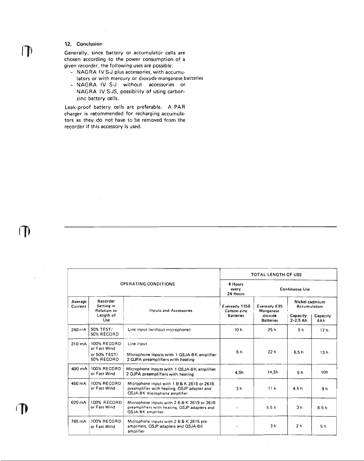
Average
Current
240mA
310mA
400mA
460mA 100% RECORD
620mA 100% RECORD
765mA
Recorder
Setting in
Relation to
Length of
Use
50% TEST; Line input (without microphone)
50% RECORD
100% RECORD line input
lor Fast Wind
or 50% TEST! Microphone inputs with 1 OSJA-B K amplifier
50% RECORD 2 QJPA preamplifiers with heating
100% RECORD
or Fast Wind
or Fast Wind
or Fast Wind
100% RECORD
or Fast Wind
TOTAL LENGTH OF
OPERATING CONDITIONS
Inputs and Accessories
4 Hours
every
24 Hours
Eveready 1150IEveready E95 Accumulators
Carbon· zinc : Manganese·
Batteries dioxide Capacity
10 h 25 h
6h 22 h
-
Microphone inputs with 1 QSJA-BK amplifier
2 QJPA preamplifiers with heating
Microphone input with 1 B & K 2619 or 2618
preamplifier with heating, QSJP adapter and 3h 11 h
QSJA·BK microphone amplifier
Microphone inputs with 2 B & K 26 19 or 261 B
preamplifiers with heatinq, QSJP adapters and
QSJA·BK amplifier
Microphone inputs with 2 B&K 2615 preamplifiers, QSJP adapters and OSJA·BK
amplifier
4.5h 5h
-
-
use
Continuous Use
Nickel·cadmium
I
I
Batteries 2-2.5 Ah
9h
6.5 h
14,5h
4.5 h
5.5 h
3h
3h
2h
Capacity
4Ah
17 h
13 h
10h
9h
6.5 h
5h
Page 16
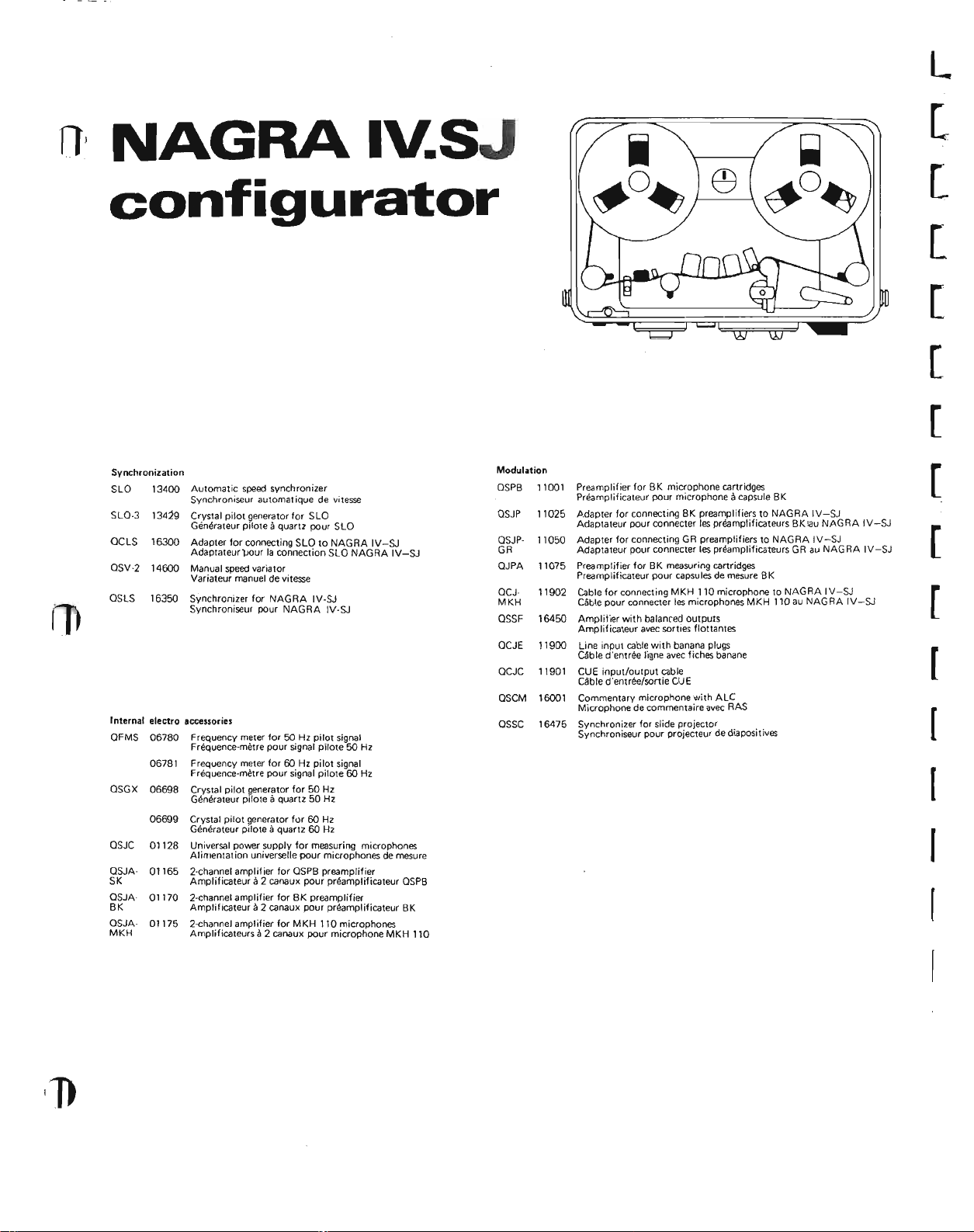
NAGRAIY.SJ
configurator
L
[
[
[
[
[
[
Synchronization
SlO 13400
SlO-3
GClS 16300
OSV-2
OSlS 16350
Automatic speed synchronizer
Synchroniseur automatique de vitesse
13419
Crystal pilot generator for SlO
Generateur piloteaquartz pour SlO
Adapter for connecting SlO to NAGRA IV-SJ
Adaotateur
14600
Manual speedvariator
Variateur manuel de vitesse
Synchronizer for NAG RA IV-SJ
Synchroniseur pour NAGRA IV-SJ
pour
la connection SlO NAGRA IV-SJ
f
Internal electro accessories
OFMS 06780 Frequency meter for 50 Hz pilot signal
QSGX
QSJC 01128 Universal power supply for measuring microphones
QSJASK Amplificateura2 canaux pour prearnpliticateur QSPB
OSJA
BK Amplificateura2 canaux pour preamplificateur BK
OSJAMKH
Frequence-rnetre pour signal pilote 50 Hz
Frequency meter for 60 Hz pilot signal
06781
Frequence-rnetre pour signal pitote 60 Hz
06698 Crystal pilot generator for 50 Hz
Generateur piloteaquartz 50 Hz
Crystal pilot generator for 60 Hz
06699
Generateur oitoteaquartz 60 Hz
Alimentation universelle pour microphones de mesure
2-channel amplifier for QSPB preamplifier
01165
2-channel amplifier for BK preamplifier
01170
01175 2-channel amplifier for MKH 110 microphones
Amplificateurs il2 canaux pour microphone MKH 110
Modulation
OSPB 11001
QSJP 11025
QSJP- 11050
GR
QJPA
11075
QCJ-
11902
MKH
16450
QSSF
OCJE 11900
QCJC
11901
16001
QSCM
16475
OSSC
Preamplifier for BK microphone cartridges
Preamplificateur pour microphoneacapsule BK
Adapter for connecting BK preamplifiers to NAGRA IV-SJ
Adaptateur pour connecter les preamptlficateurs Bk
Adapter for connecting GR preamplifiers to NAGRA IV-SJ
Adaotateur pour connecter les prearnplificateurs GR au NAGRA IV-SJ
Preamplifier for BK measuring cartridges
Preamplificateur pour capsulesde mesure BK
Cable for connecting MKH 110 microphone to NAGRA IV-SJ
Cable pour connecter les microphones MKH 110 au NAGRA IV-SJ
Amplifier with balanced outputs
Amplificateur avec sorties tlottantes
Line input cable with banana plugs
Cable d'entres ligne avec fiches banane
CUE input/output cable
Cable d'entree/sortie CUE
Commentary microphone with AlC
Microphone de commentaire avec RAS
Synchronizer for slide projector
Synchroniseur pour projecteur de diapositives
iau
NAGRA IV-SJ
[
[
[
[
[
(
I
Page 17

NAGRAI\l..SJ
configurator
[
[
Power supply
ATN-2
OCAS 98001
OCAW
PAR
PPO
PO
PA-R 98251
PA-4 98254
AST
Carrying eases
OHP 14120
OHC 14125
OHTP 99009 Standard carrying casewith pocket
OHTRC 99220 Leather cover for OSET
Mains power supply 110-250 V with pilot signal output
14350
Alimentation secteur 110-250 V avecsortie signal pilote
Mains cable with Swissplug
Cable d'alimentation secteur avec fiche suisse
98003 Mains cable without mains plug
Cable d'alimentation secteur sansfiche secteur
13200
Charger for PA type rechargeable cells
Chargeur pour accumulateurs du type PA
14150 Multiple connection box
Bolte de derivation
98202 Set of 12 standard cells
Jeu de 12 piles standard
Set of 15 rechargeablecells withextension 2,5 Ah
Jeu de 15 accumulateurs avec rallonge 2,5 Ah
Set of 12
Jeu de 12 accumulateurs 4 Ah
Stabilized power supply for measurements
90400
Alimentation stabilisee de laborataire
Carrying handle
Poignee
Spare carrying strap for NAGRA IV-SJ
Courraie de rechange pour porter Ie NAGRA IV-SJ
Saooche standard avec poche
Cauvercle de sacachepour OSET
4 Ah rechargeable cells
E)(ternal electro accessories
OGB 14001 10 1/2" reel adapter
OCA
OGBC 14005
OGBN 14006
OGBA 14007 AEG-type hub holder
OSM 14700
IACC 17910
OCAS 98001 Mains cable with Swiss-type plug
OCAW 98003 Mains cable without mains plug
Mechanical accessories
OTIM 14650 Tape driven timer
OLEN
OAAC 06260 Tape cleaning blade
MAG
OSH
Adaotateur grande bobine 267 mm
Start-stop cable for remote controt
14102
Cable start-stop pour commandeadistance
Normal 8 mm cinespool holder
Parte-bobine cinema (standard I
NAB-type hub holder
Porte noyau type NAB
Porte noyau type AEG
Field monitor and amplifier
Maniteur-amplificateur de reportage
Removable cell compartment for OSM and IS
Magasin arnovible d'accumulateurs pour OSM et IS
Cable d'alimentatian secteur avec fiche suisse
Cable d'alimentatian secteur sansfiche secteur
Compteur temps eruralne par la bande
14655 Tape driven metrical counter
Compteur rnetrique entralne par la bande
A.deur de bande
9OBOI
90802 Electronically-controlled degausser 110 - 117 V
14130 Lid when using 7" reels
,
Electranically-contralled degausser220 - 240 V
Demagnetiseur Acommande electronique 220 - 240 V
Demagnetiseuracommande electronique 110 - 117 V
Couvercle pour I'emploi de babines 178 mm
[
[
[
I
I
I
Page 18

I
BACKGROUND NOISE
Corresponding level with
Bruel&Kjaer cartridge
,
J
I
I
Potentiometer position "K"-------------
Linear measurement
20 Hz - 200 kHz
Measurement weighted
according to ASA A
BRUIT DE FOND
Position du potentiornetre "K"
Mesure lineaire
20 Hz - 200 kHz 38~ V
Mesure ponderee
selon ASA A
10J..!V
1/2" 1"
+4 dB +4dB
44 dB 20 dB
32 dB 10 dB
Niveau correspondant avec
capsules Brliel&Kjaer
1/2"
+4 dB
44 dB
32 dB
+4 dB
20 dB 22 dB
10 dB
1"
OdB
22 dB
14 dB
o
dB
14 dB
STOE RSPAN NUNG
"K" Potentiometer position -------------
Linearmessung
20 Hz - 200 kHz
Gediimpfte Messung
nach ASA A
11.
I
The QJPA preamplifier is calibrated
in order to obtain an average frequency response for 1/2" and 1"
cartridges (R10LF
possible, for a given measuring cartridge to better the very low fre-
quency range by adjusting an internal
element of the QJPA. In this case,
the frequency response will not be
as good with other cartridges.
=
2,7kU). It is
1/2"
+4 dB +4 dB
44 dB 20dB
32 dB
Le QJPA est regie de sorteaobtenir
une courbe de reponse moyenne pour
les capsu les 1/2" et 1" (R lOlF
2,7kn). II est possible, pour une
capsule de mesure donnee, d'arneliorer la partie TBF du spectre en ajustant un et.~ment interne du QJPA.
Dans ce cas, la courbe de reponse
sera evidemment moins bonne pour
une capsule differente.
Entsprechender Pegel mit
Kapseln Brliel&Kjaer
10 dB
Der QJPA ist zur Verwendung von
112"
und l"-Kapseln fur einen mittle-
=
ren Frequenzgang eingestellt. (R10lF
=
2,7kn). Fur Kapseln mit gegebenen Messwerten ist es moglich. den
sehr tiefen Frequenzbereich durch
Anpassung eines internen Elementes
des QJPA zu verbessern. In diesem
Fall wird [edoch bei Verwendung
einer andern als der gemessenen Kap-
1"
OdB
22 dB
14 dB
Page 19

L
I
I
QSJP
Adapter for Bru
et
& Kjeer Preamplifiers
I
ENGLISH
The OSJP is an external accessory for the NAGRA IV-SJ which
connects the Bruel
type preamplifier, as well as the
2615 and, if desired, the 2618 and
2627, to the recorder; the latter
should be equipped with the
OSJA-BK microphone amplifier and
the OSJC power supply.
The adapter is fitted with a plug
which can be connected to a microphone input of the NAG RA and a
Connector corresponding to the plug
of the Bruel
The K factor of the Bruel & Kjaer
cartridge used can be directly com-
pensated using the potentiometer
with a
&
-2 dB to +4 dB scale.
&
Kjaer 2619
Kjaer preamplifiers.
FRAN~AfS
Le QSJP est un accessoire externe du NAGRA IV-SJ qui permet
d'utiliser Ie prearnplificateur type
2619, ainsi que Ie type 2615 et, Ie
cas echeant, les types 2618 et 2627
avec I'enregistreur. Celui-ci doit
etre equipe de I'amplificateur de
microphone OSJA-BK et de l'alimentation QSJC.
Cet adaptateur est muni d'une fiche
qui se branche
phone du NAGRA et d'une prise
correspondant
amplificateurs
Un potentia metre gradue de
+4 dB permet de campenser directe-
ment Ie facteur K de la capsule
Bruel&Kjaer utilisee.
a
une entree micro-
Ii
la fiche des pre-
Bruet
&
Kjaer.
-2
DEUTSCH
Oer QSJP ist ein externes Zubeher zum NAGRA IV-SJ, mit welchem der Bruel&Kjaer Vorverstarker Typ 2619, sowie der Typ 2615
und gegebenenfalls die Typen 2618
und 2627 an das Bandgedit anzuschliessen sind. Dieses muss mit dem
Mikrophon-Verstarker OSJA-BK und
der Speisung QSJC ausqerustet sein.
Der Adapter ist versehen mit einem
Stecker, passend zur Mikrophoneingangsbuchse des Bandqerates und
mit einer Buchse passend zum
Stecker des Bruel
starker.
a
Ein van
tentiometer errnoqlicht die direkte
Anpassung an den K-Faktor der verwendeten Briiel & Kjaer Kapsel.
-2
&
bis +4 dB geeichtes Po-
Kjaer Vorver-
Page 20

I
I
Plug-in Module for
Microphone Amplifier
QSJA-BI<
NAG RA
IV-SJ
I
I
I
I
I
I
I
n
I
I
,
I
,
ENGLISH
The QSJA-BK is a switchable gain
amplifier, for capacitor measuring
microphones, which can be plugged
in inside the NAG RA. This acces-
sory makes it possible to use
&
Kjaer 2619, as well as 2615 and,
if desired, 2618 and 2627 type pre-
amplifiers with the QSJP adapter, or
the General Radio 1560
amplifier with the QSJP·GR adapter.
The amplifier, preamplifiers, adap-
ters and cartridges can function only
when the QSJG microphone power
supply is installed in the recorder.
P42
Bruel
pre-
FRANCAIS
Le QSJA-BK est un amplificateur
gain commutable pour microphone
de mesure
chableal'interieur
accessoire permet
amplificateur
2619, ainsi que Ie type 2615
cas echeant, les types 2618 et 2627
avec l'adaptateur QSJP, ou Ie
prearnplificateur General Radio
1560 P42 avec I'adaptateur
QSJP·GR.
L'amplificateur, les prearnplificateurs, adaptateurs et capsules ne
peuvent fonctionner que si I'alimentation de microphone QSJG est
mantee
streur.
a
condensateur, enfi-
du NAGRA. Get
d'utiliser
Bruel
&
Kjaer type
a
l'interieur de l'enregi-
Ie
pre-
et,
DEUTSCH
a
Der QSJA·BK ist ein Verstarker mit
schaltbarer Verstarkunq fUr Konden-
sator-Messrnlkrophone und ist im
Inneren des NAG RA eingesteckt.
Mit diesem
gende Einheiten verwendet werden:
BrLiel & Kjaer Vorverstiirker Typ
Ie
2619. sowie auch 2615 und gegebenenfalls 2618 und 2627 mit dem
Adapter QSJP. oder General Radio
Vorverstarker Typ 1560 P42 mit
dem Adapter QSJp·G R.
Der Verstarker, die Vorverstiirker,
Adapter und Mikrophonkapseln
werden durch die Mikrophonspeise-
Einheit QSJC gespeist, die in das
Innere des Tonbandgeriites einge-
steckt wird.
Zubehor konnen fol-
Page 21

Equivalent input noise
A. Linear 20 Hz to 20 kHz
B. ASA A weighted
A
Noise level on
+40 dB and 1/
Corresponding
sound level with
a
12.5mV/N/m
cartridge 24dB 17 dB
Saturation level on
C. Maximum input voltage
D. Corresponding sound level
+80 dB position
+60 dB position
+40 dB position
" 2.5/lV 1.1 /lV
2
2
1f2"
C
28
0.4
40mV
POSition
V
V
B
D
165dB
128dB
108dB
Bruit de fond
A. mesure lineaire de 20 Hza20 kHz
B. mesure ponderee ASA A
A
Tension de bruit
rarnenee
en position +40 dB
et
Niveau sonore
correspondant
avec une capsule
de 12,5 mV/N/m
de sensibitite 24dB 17dB
Niveau de saturation en position
\11"
C. tension d'entree maximale
D. niveau sonore correspondant
a
l'entree,
1f2"
pos. +80 dB
pas. +60dB
pos. +40dB
2,5/lV 1,1 JlV
2
C
28
V
0,4 V
40mV
B
D
165dB
128dB
108dB
Rauschen
A.
linear von 20 Hz bis 20 kHz
B. ASA A bewertet
A
Rauschspannung
auf den Eingang
bezogen, in Stetlunq
+40dB und Ih" der
Schalter 2,5/lV 1,1 JlV
Entsprechender
akustischer Pegel
mit einer Kapselempfindlichkeit von
12,5mV/N/m2 24dB
Ubersteuerungspegel in
!f2"
C. maximale Spannung
D. Entsprechender akustischer Pegel
C
St. +80 dB
St. +60dB
St. +40 dB
28
0,4
40mV
V
V
B
17 dB
Stellung
D
165dB
128dB
108dB
I
I
n
1
(
Dimensions: 2%" x 1%"x1"
67x58x28 mm
Weight: 3 oz - 80 9
CARTRIDGE
CAPSULE
KAPSELN
BK 1/8"
MECHANICAL ADAPTER
ADAPTATEUR MECANIOUE
MECHANISCHE ADAPTER
[IDlI]
BK
1/4"
4136
BK
1/4"
!IDID
BK 1/2"
~ 4134
4149 4163
Dimensions: 67 x 58x28 mm
Poids: 80g
PREAMPLIFIER
PREAMPLIFICATEUR
VORVERSTARKER
BK 2618
BK 2615
BK 2619
Abmessungen: 67x58 x 28 mm
Gewicht: 80 9
ELECTRICAL ADAPTER
AOAPTATEUR ELECTRIOUE
ELEKTR ISCHER ADAPTER
t-+-t--I
QSJP-BK
II
1/
II
t--:I'-I....-t
II
II
NAGRA IV-SJ
QSJA-B K
f
(
II
II
l
Page 22

f
f
r
J
I
I
Amplifier for Sennheiser
M KH
QSJA-MI<H
110
Microphone
I
J
I
n
I
I
I
,
1
ENGLISH
The OSJA-MKH is an amplifier
which can be plugged in inside
the NAGRA IV-SJ so that
Sennheiser MKH 110 and 110-1
measuring microphones can be used.
This accessory has two fixed gain
amplifier channels. The sound level
is obtained by adding 60 dB for the
MKH 110 and 80 dB for the
MKH 110-1 to the readings given by
the NAGRA. The amplifier also
makes it possible to supply power
direct to the microphone from the
NAG RA without using the OSJC
power supply. The dynamic of the
microphone is not affected by the
use of the amplifier.
FRAN9AIS
Le OSJA-MKH est un amplificateur enfichable
NAGRA IV-SJ qui permet d'utiliser
les microphones de mesure
Sennheiser MKH 110 et 110·1.
Cet accessoire comporte deux
canaux d'amplification
Le niveau sonore s'obtient en ajoutant 60 dB aux indications du
NAGRA pour Ie MKH 110 et 80dB
pour Ie MKH 110-1. II permet
d'autre part d'alirnenter directement
Ie microphoneapartir du NAGRA
sans utiliser I'alimentation OSJC.
La dynamique du microphone
pas alteree par les performances de
I'amplificateur.
a
l'interieur du
a
gain fixe.
ri'est
DEUTSCH
Der
OSJA-MKH ist ein Verstarker,
im Innern des NAG RA IV-SJ einsteckbar, der fur die Verwendung
der Messmikrophone MKH 110 und
MKH 110·1 von Sennheiser vorge-
sehen ist.
Dieses Zubehor enthalt zwei Kanale
mit einer festen Verstarkunq.
akustischen Pegel erhalt man durch
Addition von 60 dB fur MKH 110
und 80 dB fur MKH 110·1 zur An-
zeige des NAGRA Gerates. Die
Mikrophone werden mit diesem Ver-
starker vom NAGRA IV-SJ ohne
Verwendung der Speiseeinheit QSJC
gespiesen. Die Dynamik des Mikro-
phons wird in keiner Weise vom
Verstarker beeintrachtiqt.
Den
,
Page 23

The MKH 110 preamplifier can be
connected to the microphone inputs
by means of the QCJ·M KH input
cable.
Le microphone MKH 110sebranche
a
une entree microphoneaI'aide du
cable QCJ-MKH.
Das Mikrophon MKH 110 wird an
eine Mikrophoneingangsbuchse mit· .
tels des Kabels QCJ-MKH anqeschlossen.
SPECIFICATIONS
Current consumption unloaded
11 mA
Current consumption with 1 microphone 19mA
Frequency response
2.5 Hz-35 kHz ±0.2 dB
Equivalent input noise
A. linear from 20 Hz to 20 kHz
B. ASA A weighted
A
Noise level
Corresponding sound
level with M KH 110
microphone, referred
to 2.1O-sN/m
Saturation sound level
with MKH 110
with MKH 110-
QCJ·MKH connecting cable
Dimensions:
Weight: 1oz - 22 9
2
length
2
Y4"x21h"
60x67mm
12.uV
30dB 25dB
i
41h
ft -
7pV
130dB
150dB
1.50 m
SPECIFICATIONS
Consommationitvide 11 mA
Consommation en charge
avec 1 miero phone 19 mA
Bande passante
2,5 Hz-35 kHz ±O,2 dB
Bruit de fond
A. mesure lineaire de 20 Hzit20 kHz
B.
rnesureponderee ASA
B
Tension de bruit
rarnenee
de
Niveau sonore cor-
respondant avec
microphone MKH
110,
2.1O-sN/m2 30dB 25dB
Niveau sonore de saturation
avec MKH 110 130dB
avec MK H 110-1 150 dB
Cable de raccordement QCJ-MKH
Dimensions: 60x67 mm
Poids: 22g
it
l'entree
l'amplificateur
rapporte
a
A
A B
12/N
longueur 1,50 m
7
pV
TECHNISCHE DATEN
Stromverbrauch ohne Mikrophon
11 mA
Stromverbrauch mit einem Mikrophon 19mA
Frequenzgang
2.5 Hz bis 35 kHz bei ±O,2 dB
Rauschen
A. linear von 20 Hz bis 20 kHz
B . bewertet ASA A
A
Rauschspannung
auf den Verstarker-
eingang bezogen 12J.1V
Entsprechender
akustischer Pegel
mit dem Mikrophon
MKH-l10, auf
2.10-5N/m
bezogen 30 dB
Obersteueru ngspege
mit MKH 110
mitMKH 110-1
Anschlusskabel QCJ·MKH
Abmessungen: 60 x 67 mm
Gewicht: 22 9
2
I
Lange 1,50 m
7pV
25dB
130dB
150dB
B
Page 24

••
The NAGRA IV-S and IV-SJ tape recorders may be fitted with a third
track for the recording and playback of
a pilot signal which will permit subsequent synchronization. In addition to
the pilot signal, or in its place, the
third track can receive a commentary
for identifying the sequences recorded
on the two modulation tracks, or gi·
ving directives for the setting up of
these sequences; for instrumentation
application, the commentary could include instructions in order to analyze
the recordings.
The QSCM microphone is connected
to the CUE socket of the tape recorder.
A commentary can be recorded at two
different stages:
- during the recording of the modulation tracks, with or without simulta-
neous pilot signal, all previous information being erased on the three
tracks,
- during the playback of the modulation tracks, with partial erasing of the
signals previously recorded on the pi-
lot track.
The microphone system is mounted on
the housing which contains the preamplifier and the automatic level control;
the latter ensuresapractica lIy constant
output voltage when the input level varies from -20 to +10 dB in relation to
the nominal sensitivity. A high-pass filter cuts the frequencies below 250 Hz
to avoid any influence on the pilot si-
gnal in case of simultaneous recording.
In spite of the relatively low carrier
used for the FM recording, the upper
limit of the bandwidth enables excellent speech reproduction. The pushbutton connects the output of the preamplifier to the corresponding terminal of the Tuchel plug and turns on
the FM modulator of the third track
by connecting it to the tape recorder
supply.
Les rnaqnetophones NAGRA IV-S et
IV-SJ disposent d'une trolsisrne piste
pour I'enregistrement et la lecture d'un
signal pilote, qui permettra une synchronisation
gnal pilote, ou a sa place, la troisierne
piste peut recevoir un commentaire
destineaidentifier les sequences enre-
qistrees sur les deux pistes de modula-
tion, ouadonner des directives pour
Ie montage de ces sequences; en metrologie, Ie commentaire pourra cornporter des instructions pour Ie depouille-
ment des enregistrements.
Le micro QSCM se branche ala prise
CUE du rnaqnetophone. L'enregistrement du commentaire peut se faire a
deux stades differents :
- pendant I'enregistrement des pistes
de modulation, avec ou sans signal
pilote sirnultane, toute information
anterieu re etant effacee su r les trois
pistes.
- pendant la lecture des pistes de modulation, avec effacement partiel des
signaux enreqistres anterieurernent
sur la piste pilote.
La capsule microphonique est montee
sur Ie boitier qui contient Ie preamp
ficateur et Ie regulateur automatique
de sensibilite: ce dernier assure une ten-
sion de sortie pratiquement constante
lorsque Ie niveau d'errtree varie de
ulterieure.
En plus du si-
ll-
-20 a +10 dB par rapport ala sensibili-
te nomina Ie. Un filtre passe-haut coupe
les frequencss inferieures a 250 Hz,
pour
eviter
toute influence sur Ie si-
gnal pilote en cas d'enregistrement si-
rnultane, Malgre la porteuse relativement basse utilisee pour I'enregistrement en modulation de frequence, la
limite superieure de la bande passante
permet une excellente reproduction
de la parole. Le bouton-poussoir connecte la sortie du prearnplificateurala
broche correspondante de la fiche
Tuchel, et met en service Ie modulateur FM de la troisierne piste en Ie
cordant a I'alimentation du magnetophone.
rac-
Fur die Aufzeichnung und Wiedergabe
eines zur spateren Synchronisation bestimmten Pilotsignales, steht bei den
Tonbandqeraten IV-S und IV-SJ eine
dritte Spur zur Verfuqunq. Auf dieser
Spur kann, zusatzlich zum Pilotsignal
oder an dessen Stelle, ein Kommentar
aufgenommen werden, welcher die aufgezeichneten Sequenzen identifiziert
oder fur die spatere Montage bezeich-
net; bei Messdaten-Aufnahmen kon-
nen Anweisungen fUr die Auswertung
aufgenommen werden.
Das QSCM-Mikrophon wird an der
CUE-Buchse des Tonbandqerates angeschlossen. Die Aufzeichnung eines
Kommentares kann zu den zwei folgenden Zeitpunkten stattfinden :
- bei der Aufnahme der Tonspuren,
mit oder ohne Pilotsignal; dabei werden aile fruher aufgenommenen Si-
gnale auf den drei Spuren geloscht;
- bei der Wiedergabe der Tonspuren,
wobei die auf der Pilotspur vorhande-
nen Signale teilweise geloscht werden.
Die Mikrophonkapsel ist auf dem
hause
montiert, das den Vorverstiirker
und den automatischen Empfindlichkeitsregler enthalt. Dieser Ernpfindlichkeitsregler ergibt eine praktisch
konstante Ausgangsspannung, wenn
der Eingangspegel in Bezug auf die
nominale Empfindlichkeit von - 20 dB
bis +10 dB variiert. Ein Hochpassfilter
sperrt die tiefen Frequenzen unterhalb
von
250
Hz, damit bei gleichzeitiger
Aufzeichnung das Pilotsignal nicht beeinflusst wird. Trotz des relativ niedrigen Traqers bei der FM-Aufzeichnung,
ist die obere Grenzfrequenz
ausgezeichnete Sprachwiedergabe
reichend. Durch die Drucktaste wird der
Ausgang des Vorverstarkers an den ent-
sprechenden Anschluss der Tuchel-
Buchse gelegt, und dem FM-Modulator
der dritten Spur wird die Speisespannung des Tonbandqerates zuqefuhrt.
fur
Ge-
eine
aus-
SPECI FICA TlONS
Normal output voltage with automatic level control 700 mV, determining a frequency deviation of ±20
Operating range of the automatic level
control from 3 to 100 ,ubar
Stabilized supply voltage -10 V,
sumption 2.5 mA
Dimensions
cable length 4' 8"
Weight with cable and plug 7 oz
4 3/4x1 5/8x1 1/8 ",
%
con-
SPECIFICATIONS
Tension nominale de sortie avec
glage automatique de sensibilite
700 mV, determinant une excursion
de
frequence
Plage de regulation automatique de la
sensibi lite de3a 100 IJbar
Tension d'alimentation stabilisee -10V,
consommation 2,5 mA
Dimensions 120x40x28 mm, cable
de 140 cm
de ±20
%
re-
TECHNISCHE DATEN
Nominale Ausgangsspannung mit
automatischem Empfindlichkeitsregler
700 mV; diese Spannung ergibt einen
Frequenzhub von ±20%.Regelbereich
des automatischen Empfindlichkeitsre·
gler: 3 bis 100 pbar. Stabilisierte
Speisespannung
2,5mA
Aomessungen 120 x 40 x 28 mm,
Kabel 140 cm
-10
V, Stromverbrauch
Page 25

recorded, with about 0.001 % accuracy.
The QSV2 speed varier can be connected to the SPEED VARIER
INPUT when it is necessary to
extend the synchronization range
(±12%).
The meter gives two readings:
- if the NAGRA SPEED switch is
on FREE, i.e. without speed slaving,
it indicates the frequency error between the playback pilot signal frequency and that of the svnchronization signal. One complete oscilla-
tion of the needle left/right/left, in
two seconds, indicates a speed
ference of 1%.
- if the same switch is set on
SLAVE, the synchronizer adjusts
the tape speed, slaving the playback
pi lot signal to the reference signal.
The meter needle then shows the
phase difference between the two
signals and should not oscillate.
If the desired speed correction is
beyond the slaving capability of the
device (±3%), the meter needle
begins to oscillate; use of the QSV2
speed varier will extend the slaving
range by ±12%.
The PILOT LEVEL indicator
becomes black if there is no pilot
signal or it is not sufficient for good
synchronization.
dif-
egale la
precision de I'ordre de 0,001%.
La deuxierne prise d'entree SPEED
VARIER INPUT est destinee
voir
lorsqu'il est necessaire d'elarqir la
plage de synchronisation (± 12%).
Le qalvanornetre donne deux indio
cations:
- en position FREE du commuteteur NAGRA SPEED, c'est-a-dire
sans asservissement de vitesse, il
affiche t'ecart entre la frequence du
signal pilote lu et celie du signal de
synchronisation. Une oscillation
complete de I'aiguille gauche/droite/
gauche en deux secondes correspond
a
une ecart de vitesse de 1%.
- en position SLAVE du rnerne
commutateur, Ie synchronisateur
regie la vitesse de defilement de la
bande, en asservissant Ie signal pi-
lote lu au signal de reference.
L'aiguille du qalvanometre indique
alors I'ecart de phase entre les deux
signaux; elle ne
Au cas
corriger excede les possibilites
d'asservissement du dispositif (±3%),
I'aiguille du galvanometre se met
osciller; le variateur de vitesse QSV2
permit d'elarqir cette plage d'asser-
vissement de ± 12%.
Le voyant PILOT LEVEL devient
noir si le signal pilote est absent ou
insuffisant pour une bonne svnchro-
nisation.
vitesse
Ie variateur de vitesse QSV2,
originale avec une
doit
au
I'
ecart de vitesse
a
rece-
plus osciller.
einer Genauigkeit van etwa 0,001%
abzuspielen.
Die zweite Eingangsbuchse SPEED
VARIER INPUT dient zum Anschluss des Geschwindigkeitsreglers
QSV2, falls der Regelbereich auf
±12% erweitert werden muss.
Das Instrument gibt zwei verschie-
dene Anzeigen:
- in
Stellunq
NAGRA SPEED, das heisst ohne
Geschwi ndig kei tsnach rege lung, ze igt
es den Unterschied zwischen dem
abgetasteten Pi lotsignal und dem
Bezugssignal an. Eine volle Schwing-
ung links/rechts/links in zwei Sekun-
den entspricht einem Geschwindig-
keitsunterschied van 1%.
- in Stellung SLAVE des gleichen
Schalters regelt der Synchronisator
die Bandgeschwindigkeit, indem es
das abgetastete Pilotsignal mit dem
Bezugssignal synchronisiert. Der
strumentenzeiger gibt in diesem
Faile den Phasenunterschied der
beiden Signale an; er dart nicht
schwingen.
a
zugleichende Geschwindigkeits·
unterschied die Nachsteuerunqsrnoq-
lichkeit der Vorrichtung (±3%), so
a
beginnt der Zeiger zu schwingen; der
Geschwindigkeitsregler QSV2 erweitert diesen Bereich
Das Schauzeichen PILOT LEVEL
wird schwarz, wenn das Pilotsignal
nicht vorhanden oder zu schwach
fur gute Synchron isation ist.
FREE des Schalters
Uberschreitet
urn
±12%.
der
In-
aus-
Applications
- Filming on playback
- Transfer of sound recorded on a
NAG RA to a film or perforated
tape, facsimiles
- Correlation of signals recorded
on several recorders
- Synchronous measurements etc.
SPECIFICATIONS
Nominal synchronization range
±3%
Current consumption
Dimensions:
Weight: 13 oz - 360 9
5V2"
x 3
140x82x30 mm
8.8mA
1
/4"
x
1
V4"
Applications
- Tournage en playback
- Transfert du son NAG RA sur film
ou bande perforee, utilisation
pour fac-similes
- Correlation des signaux enreqi-
stres Sur plusieurs appareils
- Mesures synchrones etc.
SPEC IF ICATIONS
Plage de synchronisation propre
±3%
Consommation
Dimensions: 140 x 82 x 30 mm
Poids: 360g
8,8
mA
Anwendungsbeispiele:
- Filmen in Playbackverfahren
Uberspielen des Tons vom
NAGRA·Gerat auf Film, perforiertes Tonband sowie fur
simile
Korrelation yon auf mehreren
Gersten aufgezeichneten Si-
gnalen, synchrone Messungen.
TECHNISCHE DATEN
Eigener Nachsteuerungsbereich der
Synchronisation ±3 %
Stromverbrauch 8,8 mA
Abmessungen: 140 x 82 x 30 mm
Gewicht: 360g
Fak-
Page 26

CHANNEL
I
LINE
!?i ~
~ I
""<.
CHANNEl
2
L".
-
--
~---
IOKE
--,
I
8S3a
81
dB .8W·cO
noPESr~
"
1I2"\III.~
96
J;1.5nF
aC4
aJ8
CHANNELl
-lOG
61
P\. •••V84CK
OUTPUT
CHANNEL 2
-lOG
"
PlAYUO<
OUTPUT
UNE
;~
I
MIKE
I
I
,
I
I
I
:~
I MIKE
,
I
I
I
I
act
lSnF
E.I,"",@- _
-lOR
dB '1O~ •
1
WITHOUT
L - -
-PILOT VERSION
J
ONLY
I"
L _
@}~EYEl
"
.o
:n
0;>
I
RECORD
T1
~
STOP"; I
hL~-
PLAYBACK;
I
loll POWER
CAlLE COLOUR
1 •
2 •
l •
4 •
I
..
7 •
..
I
o
I •
At
I MICROPHg::
1: NICROPH&DUtECT AMPLlFI£R
: ATltHU' "'PUT AMPLIFIER R CHAHNEL I
AI DlRECf OUTPUT
A.
A7 PE.' LEVELvEl IHOICATOR5
.1 AV£RAGE LE NES AMPltFtER
.1 UNf&.PHO AMPLI'IER
A. 10
~ ~ AEI"EAE:~~TfA
: ~ ~~E;ES s~~n't«~G
AI5
::~ ~~LTAG£ •• SPfE
COPE
BROWN
RtO
ORANGE
YEllOW
GREEN
OLUE
VIOLET
GREY
WHIT[
BLACK
PINk
MPL1FIEfI
AlTfHUA~g:&D4RECT PM:
~~::g
lOUOSPE.A.I<E~5CILl'&TOR
NE~~R
~NPllFiER ~~::PllFIER
.MPlFIE
OUTPUT
tHDI~~~~~flf
TEMPORIZf: STA8t1IZER
CH4N:~ ~
CHAHHEl
R CHANNEL 1
8'
51
-nv •
r~~
TO
1.16
,&
1
BDSI~
SPEED & POWER
TACHO
HEAD~
T:\.
aS1
:
... b
- - - - __ a
~
~
CRYSTAL
I
:l-~
I
r
I
L:
Al5
FR
1
I
•
I
I
I
I
I
L
Page 27

J
.....J
1
1
5=
6=:
ExTERNAL VIEW
OF CHASSIS
CONNECTOR OR
PLUG FROM THE
SOLDERING SIDE
MICROPHONE CHANNEL1:channell microphone input connector, identical to 36
Gain selector for channel 2 microphone amplifier, 3 positions, -1-40•
+60 and +80 dB
Gain selector for channel 1 microphone amplifier, identical to 38
MICROPHONE TYPES: B
7=
8
=
&
K cartridge type selector
G
CHANNEL 2: channel 2 multiple connector
(.;\ 1=VAR. LEVEL IN: line input, input impe-
o
0
o
3
<2)
CD
1 2=
®
dance 100 kn, input voltage> 1 mV
-10G:stabilizedvoltage-l0V
4=Playback output: output voltage 10 mV at
® OdB, loed >47 kn
7=ground
EXTERNAL VIEW
Of CHASSIS
CONNECTOR OR
PLUG FROM THE
SOLDERING stOe
CD
CHANNEL1:Channell connector, identical to 41, shown with
strap plug to reintroduce the playback signal into the di rect chain
(switch 10mustbeon LINE)
e
OUTPUTS: line output connector
o
0 CD
'7'
o
\V
®
=
LINE OUT 2: line output, channel 2, out-
1
put voltage 100 mV at 0 dB in a load greater
than 10kn
2
= -lOG: stabilized output voltage -10 V
® 3 = LINE OUT 1: line output channell, out-
put voltage 100 mV at 10 dB in a load
greater than 10 kn
4 = unstabilized negative supply voltage
EXTERNAL VIEW
OF CHASSIS
CONNECTOR OR
PLUG FROM THE
SOLDERING SIDE
5 = -10 R: stabilized voltage -10 V available
only during recording
6 = STOP: motor stop control terminal (con-
nect to -10 V to stop)
=
ground
7
c
c:
PILOT: pilot signal input for the 3rd track
1 = ground
=
CLAPPER: reference oscillator or crystal
2
pilot generator control terminal
EXTERNAL VIEW
OF CHASSIS
CONNECTOR OR
PLUG FROM THE
'SOLDERING SIDE
LINE OUTPUT 2: channel 2 line output on banana jacks
LINE OUTPUT 1: channell line output on banana jacks
CUE: connector for recording and playback on the third track
EXTERNAL
VIEW
OF CHASSIS
CONNECTOR OR
PLUG FROM THE.
SOLDERING SIDE
3 = Xtal: 50 or 60 Hz internal crystal pilot
generator output
=
PILOT IN: pilot signal input
4
1=CUE IN: modulation signal input
2= -lOG: -10Vstabilizedvoltage
=
PILOT OUT: pilot signal output
3
=
-10 V: stabilized voltage available only
4
during recording
=
-10 V
FM:
5
FM modulator
= CUE OUT: signal output (direct or recorded)
6
7
=
ground
voltage terminal to activate the
G
POWER PACK: connector for external power supply
EXTERNAL VIEW
OF CHASSIS
CONNECTOR OR
PLUG FROM THE
SOLDERING
SIDE
e
Fixture for handle or strap
e
Case fixing screw
o
Plate showing recording and playback equalization
1 = -BATT.: negative pole of the battery box
=
+BATT.: positive pole of the battery box
2
and ground
3 = STOP: motor stop control terminal (con-
nect to -10 V to stop)
=
SPEED CORRECTION: tape speed correc-
4
tion signal input
5 = EXTERNAL -12 V to -30 V: 12 to 30 V
external power input, negative pole
=
-10 G: -10 V stabilized voltage
6
r-
Page 28

· 1033 CHESEAUX LAUSANNE
SWITZERLAND
I
TEL.(021) 91 21 21
TELEX: 24 392
I
I
I
I
I
I
I
~,,~.(;t~
~,'·:·t.':.:~;r:~;~·;·\;:i'·~~
,<PRINTED IN SWITZERLAND BY KUDEI.SKI SA.
I
I
I
••
Page 29

CONTINUATION
CALffiRATION DATA SHEET
WORK ORDER/CERT. NUMBER CYCLE
A-1
MANUFACTURER
CONTROL NUMBER
NAGRA
MODEL NUMBER
IV-SJ
I
DESCRIPTION
MAG. TAPE RECORDER
I
CAL DATE
I
DUE DATE
I
ASSET NUMBER
I
REPCODE
SHIP TO ADDRESS
SIKORSKY AIRCRAFT
6900 NORTH MAIN ST.
STRATFORD, CT. 06497
I~~-'
.}. . PARAME1'ERTESTED TESTSPECIFICATIONS STANDARDIAPPLIED BEFOREADJUSTMENT AFTERA_
FREQUENCY RESPONSE 25hz-35Khz
DIRECT CH1
.,:n'.~.
DIRECTCH2
DIRECT CH1
DIRECT CH2
SIGNAL TO NOISE
+-O.3db
+-O.3db
GAIN
+-1.0db
+-1.0db
>66db 1Vrms@1Khz
@15ips
Odb1Khz @15ips
If}
~'
','
0.
lBER
;
r~.
.
'
{.,
,
.
-
'.'
,
,
TID-S-1201-01 (12/96)
-
...
.'
,
Page 30

E :
E ~
co co
It) .-
..•
358
mm
14.1 "
E :
E
co
It)~
,.:c:>
•..
~ci
E
E
It)
N
• on
Go
E
E
..,
,..
E _
E ;...
•••• "!
~
•••
N
..
..,
E
co
.'
':(-
E
•..
c:>
N
E •
E~
C\.. •
0>'"
E
E ;.,
Page 31

G-- .
Page 32

CHANNEL(j]
CIiANNELffi
FILTERS
BOX
~
TAPE
DECK
•
/
'
..ll
,
-, 0'"
,
,
.•.
5 .,..,0
\
.,!
;
.1
co!
.JI) ( j)'I.20
·~if
.I, ,,-. )
'PPt', track):
I ,
.1
, I
','o'~'
.10 .•
I , \
"r(m'j
eo ~
y!
• ~ 00' /
s /'
.lr~.4~
.e .,
'f!)\
,10
'-. I
o/c..al
61
51
BIAS
J .
e
®
I
t
I
,
,
,
.I
~l~
I
LIGHT
: TO A24
I
I
,
,
18
,
I
~--,---
-lOV
-lOR
A17 A18
RECORD
HEAD
3,75" 7,S"
ERASE
HEAD
\ I
---~~
O,-lAPE-
,
...
CUE
(PHONE)
-~'----4------,
our
A21
LIGHT
TEMP,
"ov4J
~'---~-----------~--~~~-UVR,
l ~ ,
. ..:B:;::S~IC4-__
_,O:J
°
BCR2
1N1,14$
...!8!!.)
°
••
8 : )
I
0..>6L7"
s - 'o--'-~!!-_!!<...-<>
E3
;;>
I
85
89
51
(f
'
BS9 '
Q)
A 16 RECOROING PREAtr.4PLlFrER
A 17 RECORDING AMPLIFIER CHANNEL T&2
• BIAS OSCILLATOA
A 16 BIAS OSCillATOR COil
A 19 PLAVBACK AMPLIfIER CHANNEl 1&2
~S!J_- - ,
CR3B2 ~
IN4'''' • IN
REW~ONLY
....rt
e
PLAYBACK
HEAD
4II1II
e
I
.•••. PILOT
e
CHANNEL
UPPER
TRACk
CHANNEL
LOWER
TRACK
III
CHANNEL 3
HEAD
Q.AP .6'1 TO .U.V
'TF-I<r-UNCTION
PiLOT IN
.
.........
"1IAIO A9
'<0 ••••••••••
:,.,12:••••....•• '
AS A6 ,.7
BOX INTERCONNECTION
"0
ALL CONNEC10RS VIEWED FROM THE OUTSIDE
KUOElSKI SA. O""'.NAOR. ••. "''''G''''
CH· 1033 CHUE,t,UX HE'llYORt(.
TAPE DECK INTERCONNECTION
,,"GNElIC
SootiU"~nd __ ._ .....•~'~~~'. ~'_
.,.
"CWMOO'S IN(:
N't
lOCUli
Page 33

QSV2
SPEED VARIER
J
QSV2
for
NAGRA 4.2, IV-S and IV-SJ
QSV2
,.-.....
.c
j'
ENGLISH
When connected to the Nagra, the
Speed Varier allows all 3 speeds
15"/s - 7.5"/s - 3.75"/s to be varied
manually up to
Sound transfer applications:
- To adjust the pilot signal
frequency to a reference.
- To compensate for a missing
pilot signal or to adjust the syn-
chronization when the pilot
signal frequency fluctuates.
Dimensions: 5 %"
Weight: 1 Ib(0.450 kg)
±12%
1
x 2
/z"
X 1 %"
(142 x 62 x 38 rnrn]
FRANCAIS
Le variateur de vitesse permet de
faire varier manuellement la vitesse
de defilement du Nagra de±12 %
II est utillsableato utes les vitesses
(38,1 cm/s; 19,05 cm/s; 9,525
Applications:
Transfert d'un ruban dont Ie
signal pilote provenait d'une cameraavitesse hors tolerance.
Transfert d'un ruban dont Ie
signal pilote
interruptions.
Dimensions: 142x62x38 mm
Poids :
comporte
0,450 kg
cm/s).
des
DEUTSCH
Das QSV Zubehor welches am Nagra
angeschlossen wird, erlaubt die
3 Band-Geschwindigkeiten
(38,1 cm/s; 19,05 cm/s; 9,525 cm/s)
von Hand um±12
Anwendung bei Oberspielungen :
Anpassen der Pilotton-F requenz
an die Referenz Frequenz.
- Ausgleichen schwanker.der oder
fehlender Pilotton Signale.
Abmessungen: 142x62
Gewicht:
0,450
%
x
38 mm
kg
Page 34

••••••
I
I
I
QSLS
External Synchronizer for
...•
,
.
.~
NAG RA
IV-S and IV-SJ
ENGLISH
External synchronization accessory
for varying the tape speed of the
NAGRA to make the playback pilot
signal synchronous with the pilot
reference signal received by the
recorder.
I
The OSLS can be connected to the
PILOT
hand side of the NAGRA IV-S or
IV-SJ.
The synchronization signal must be
applied to the PILOT INPUT con-
nector which also carries the
reference signal from the internal
crystal pilot generator of the
NAG RA; this signal can be used tor
synchronization. This offers the
possibility of playing back the signal at the speed at which it was -
&
CUE inputs on the right-
Accessoire externe de synchronisation qui permet de modifier la
vitesse de defilement du NAGRA
pour rendre Ie signal pilote lu synchrone avec Ie signal pilate de
reference entrant dans l'appareil.
Le OSLS se raccorde aux prises
PILOT et CUE situees sur Ie cote
droit du NAGRA IV-S au IV-SJ.
Le signal de synchronisation doit
etre introduit par la prise PILOT
INPUT sur laquelJe arrive egalement
Ie signal de reference du generateur
a
quartz interne du NAGRA, qui
peut etre utilise comme signal de
synchronisation. Cette possibilite
permet d'obtenir
signal dont la vitesse de defilement
FRAN~AIS
a
la lecture un
DEUTSCH
Externer Synchron isator, welcher
erlaubt die Bandlaufgeschwindigkeit
des NAG RA-Gerates zu verandem,
urn das abgetastete Pilotsignal mit
einem externen Bezugssignal zu synchronisieren.
Der QSLS wird an den Buchsen
PILOT und CUE auf der rechten
Seite des NAGRA IV-S und IV-SJ
angeschlossen.
Das abgetastete Synchronisationssignal wird uber den Stecker PI LOTINPUT eingefUhrt; am gleichen
Stecker erscheint das Bezugssignal
des im NAGRA Tonbandgeriites eingebauten Ouarzgenerators. Dies er-
moglicht es, das Band mit der Originalaufnahmegeschwindigkeit bei
'I
I
Page 35

QSCM
Commentary Microphone
for NAGRA IV-S and IV-SJ
ENGLISH
Hand microphone for recording a commentary on the pilot track of the
NAGRA IV-S and IV-SJ tape recor-
ders,
FEATURES
Capacitor microphone system: intelligibility of the message is heiqhtened.
Sintered bronze acoustical screen effectively protecting the diaphragm.
Built-in preamplifier which gives out a
strong useful signal.
Automatic level control: optimum
modulation without any manual
adjustment.
Filters determining a bandwidth adapted to the speech reproduction.
Operation hv
lockinq nush-hut
ton
FRAN~AIS
Microphone manuel pour I'enregistrement d'un commentaire sur la piste
pilote des rnaqnetophones NAGRA
IV-S et lV-SJ_
CARACTER ISTIQUES
Capsule microphoniqueacondensateur :
l'intelliqibilite du message est accrue.
Ecran acoustique en bronze tritte, protegeant efficacement la membrane.
Prearnptificateur incorpore, qui delivre
un signal utile important.
Regulateur automatique de sensibilite :
modulation optimale sans aucun regiage manuel.
Fi Itres determinant une bande passante
adapteeala reproduction de la parole.
Mise en service par bouronpoussov
DEUTSCH
Handmikrophon fur die Aufzeichnung
eines gesprochenen Kommentares auf
der Pilot-Spur der NAGRA Tonbandqerate IV-S und IV-SJ.
MERKMALE
Kondensator-M ikrophonkapsel fur
eine bessere Sprachverstiind lichkeit.
Nahbesprechungsschutz aus Sinterbronze.
Eingebauter Vorverstiirker mit hohem
Ausgangspegel.
Automatischer Empfindlichkeitsregler
zur optimalen Aussteuerung.
Filter zur Bestimmung eines, fur die
Sprache geeigneten, Frequenzganges.
Ein- und Ausschalten rnitte ls verriegelbarer Drucktaste .
Page 36

The QSJA-BK amplifier has two
channels with switchable sensitivity,
on three positions: +40, +60 and
+80 dB.
The sound level measured using the
microphone is obtained by adding
the setting of the amplifier gain
selector to that of the attenuator
and to the reading on the measuring
instrument.
L'amplificateur QSJA-BK
deux canaux d'amplification dont
Ie gain est commutable, separernent,
sur trois positions: +40, +60 et
+SOdB.
Le niveau sonore rnesureaI'aide du
microphone s'obtient en additionnant I'indication du selecteur de gain
de I'amplificateur de microphone
avec celles de l'attenuateur et de
I'instrument de mesure de I'enregi-
streur.
possede
Der Verstiirker QSJA-BK ist zweikanalig, mit
kungseinstellung durch je einen drei-
stelligen Schalter, mit den Stel-
lungen +40, +60 und +80 dB.
Den mit dem Mikrophon gemes-
senen akustischen Pegel erhiilt man
durch Addition der eingestellten
Werte an diesem dreistelligen Schalter und an dem
mit dem vom Messinstrument angezeigten Wert.
unabhanqiqer Verstar-
Heuptabschwecher
r
I
L
,..
I
[
When the QSJA-BK amplifier is used
care should be taken that the main
attenuator is not set higher than the
+40 dB position which is indicated
by a triangular index. Beyond this
position there is a risk of saturating
the input stages and the microphone
amplifier gain should be reduced
using the three-position switch. In
the +80 dB position the input level
is no longer limited, except by the
performance of the microphone car-
tridge. With.a third switch, com-
mon to both channels, the gain can
be selected according to the
meter of the cartridge used. The
exact sound level is thus obtained
direct in relation to the sensitivity
of the cartridge. This is valid for the
following
%":
1j2": 4133, 4134, 4149 and 4163
1 ": 4144, 4145, 4146 and 416.1-
With the
correction must be made to account
for its sensitivity difference.
4135
Bruel
&
Kjaer cartridges:
I/.;"
4136 type cartridge a
dia-
En utilisant cet amplificateur, il taut
veillerane pas depasser la position
+40 dB de l'attenuateur principal du
NAG RA, position reperee par un
index triangulaire. Au-dela de cette
position, il y a risque de saturation
des etaqes d'entree, et il faut alors
reduire Ie gain de I'amplificateur de
microphone
tateuratrois positions. Sur la position +SO dB, Ie niveau
plus limite, si ce
performances de la capsule micro-
phonique. Un troisieme selecteur,
commun aux deux canaux, com-
mute Ie gain suivant Ie diarnetre de
la capsule utllisee, Le niveau sonore
exact est ainsi obtenu directement,
en fonction de la sensibilite de la
capsule. Ceci est valable pour les
capsules Bruel
%":
4135
% ":
4133, 4134, 4149 et 41 63
1 ": 4144, 4145, 4146 et 4161.
Avec la capsule
necessaire d'effectuer une correc-
tion qui tient compte de sa sensi-
bilite differente
Ie niveau sonore reel.
a
I'aide de son cornrnu-
d'entree n'est
n'est
que par les
&
Kjaer suivantes:
%"
type 4136, if est
pour obtenir
Bei der Verwendung dieses Verstar-
kers muss darauf geachtet werden,
dass die +40 dB Stellung des
NAGRA-Hauptabschwiichers - durch
ein Dreieck gekennzeichnet - nicht
uberschritten wird. Bei hoheren
Stellungen besteht die Gefahr einer
Ubersteuerung der Eingangsstufe; in
diesem Faile muss der
regler des Mikrophonverstarkers in
eine andere Stellung gebracht werden. 1st die Stellung +80 dB
erreicht, so ist der Eingangspegel
nur noch durch die Mikrophondynamik begrenzt. Ein dritter Schalter,
gemeinsam fur beide
die
Verstarkunq
Kapseldurchmesser an. Der richtige
akustische Pegel wird somit der Kapselempfindlichkeit entsprechend,
fur folgende Bruel&Kjaer Kapseln
direkt erhalten:
'A ":
4135
'h":
4133, 4134,4149 und 4163
1 ":
4144, 4145, 4146 und 4161.
Bei Verwendung der. 1/4 "-Kapsel
4136 muss die erhaltene Ablesung
unter
Beriicksichtlqunq
chenden Kapselempfindlichkeit kor-
rigiert werden.
Verstarkunqs-
Kanale,
an den verwendeten
passt
der abwei-
[
[
[
[
r
I
I
SPECIFICATIONS
Power consumption
O.S mA on -10 V
0.3 mA on +120V
Sensitivity of the microphone inputs
for which a direct reading is obtained
1 "position 50
1j2" position 12.5
'/4"
position 4mV/N/m
Frequency response
2.5 Hz to 35 kHz ±0.3dB
Attenuator accuracy ±0.2 dB
mV IN/m
mV/N/m2
I
SPECIFICATIONS
Consommation
O,S mA sur Ie -10 V
0,3 mA sur Ie +120 V
2
2
Sensibitite des entrees microphone
pour laquelle une lecture directe est
obtenue
position 1 "
position
position 1/4
Sande passante
'h"
II
') 1'1H
50 mVIN/m
12,5
4mV/N/m2
7 ::.
11'1I<H'r+0 1 rl R
2
mV/N/m2
TECHNISCHE DATEN
Stromverbrauch 0,8 mA auf -10 V
0,3 mA auf +120 V
Empfindlichkeit der Mikrophoneingiinge bei denen die Ablesung direkt
erhalten wird
Stellung 1
Stellung
Stellung
Frequenzgang
II
%
II
'/4
II
2,5 Hz bis 35 kHz bei ±O,3 dB
50 mV/N/m
12,5
4 mV/N/m
mVIN/m
2
2
2
Page 37

L
SPECIFICATIONS (Typical Values)
Power consumption on 120V
1.3mA
Frequency response
±0.2 dB from 2.5 Hz to 35 kHz
Equivalent input noise
Measurement taken with
QSJA-BK preamplifier, with
adjustment potentiometer set on
+ldB
A. linear from 20 Hz to 20 kHz
B. ASA A weighted
A
Noise level
Corresponding
sound level with
a lh" cartridge,
sensitivity
12.5 mV/N/m
Input saturation level (potentiometer on +1 dB) 37 Veff
Corresponding sound level for a
lh" cartridge, sensitivity
12.5 mV/N/m
Dimensions: 31h" x 1
Weight: 4 oz - 110 9
10JlV
2
31 dB
2
80 x 40mm
%"
the-
B
4JlV
23dB
165dB
SP~CIFICATIONS
(valeurs typiques)
Consommation sur 120
Bande passante
2,5 Hz-35 kHz ±0,2 dB
Bruit de fond
Mesure effectuee avec un prearnpli-
a-
ficateur QSJA-B K, potentiornetre
de reglage en position rnediane
(+1 dB)
A. mesure
B. mesure ponderee ASA A
Tension de bruit
rarnenee
Niveau sonore cor-
respondant avec une
capsule lh" d'une
sensibilite de
12,5 mV
Niveau de saturation
(poterrtiornetre de reglage en position rnediane +1 dB) 37 Veff
Niveau sonore correspondant avec
une capsule lh" d'une senslbilite de
12,5 mV/N/m
Dimensions: 80 x 40 mm
Poids: 110g
lineaire de 20 Hz
a
l'entree 10
2
IN/m
2
31 dB 23 dB
V
1,3 mA
a
20 kHz
A B
IlV
4
a
l'entree
165dB
JlV
TECHNISCHE DATEN
(Typische Werte)
Stromverbrauch 120 V 1,3 mA
Frequenzgang
von 2,5 Hz bis 35 kHz ±0,2 dB
Rauschen
Messungen vorgenommen mit Vor-
verstarker QSJA-B K, Potentiometer
in Mittelstel1ung
A. linear von 20 Hz bis 20 kHz
B.
ASA A bewertet
Rauschspannung
auf den Eingang
bezogen 10
Entsprechender
akustischer Pegel
unter Verwendung
einer1h"-Kapsel mit
der Empfindlichkeit
12,5 mV
Ubersteuerungspegel des Eingangs
(Potentiometer in Mittelstel1ung
+1
Entsprechender akustischer Pegel
unter Verwendung einer
mit der Empfindlichkeit
12,5mV/N/m2
Abmessungen: 80 x 40 mm
Gewicht: 110 9
IN/m
dB) 37 Veff
(+1
dB)
A B
Jl
V
4
JlV
2
31 dB 23 dB
1h
"-Kapsel
165dB
l
[
[
[
[
[
CARTRIDGE
CAPSULE
KAPSELN
BK 1/8"
[ID8]
BK
4136
BK
~
BK
[ID3J
1/4"
1/4"
1/2"
4134
4149~4163
MECHANICAL ADAPTER
ADAPTATEUR M~CANIQUE
MECHANISCHE ADAPTER
PREAMPLIFIER
PREAMPLIFICATEUR
VORVERSTARKER
BK 2618
BK 2615
BK
2619
ELECTRICAL ADAPTER
ADAPTATEUR ELECTRIQUE
ELEKTRISCHER ADAPTER
•...•.+--1
QSJP-BK
1--
II
NAGRA IV-SJ
II
1\
--&--1
OSJA
11
II
II
II
[
"
r
Page 38

Results obtained on a NAG RA IV-SJ with different values of R 10LF comp according to the used cartridge.
Resultats obtenus sur un NAGRA IV-SJ avec differentes valeurs de Rl0LF comp suivant les capsules utilisees,
Auf einem NAGRA IV-SJ erhaltene Ergebnisse, bei verschiedenen Werten yon Rl0LF comp fUr 1/2" und l"-Kapseln.
8
d
-
5
R,o
LF cornp,
=
3,3 1<0.
I I I I
I I
I I I
/SOPF(I"")
~
/
,
'lapF
3L5 6 8
Rio
LF cornp.
=
2,7 kfl
!"'.
II
-
...•.
/
I I I II
J
SOpF (1""
,.
18pF
_.
-
dB
I'/,
-i.,
-
I
I'-
I
I
o
I
I
f-~
i/
-
_.
!
I
I--
10 Hz 3 4 5 6 8 10 Hz
2
I I
J
('1,"1-
f-
-3
-5
-8
-1
-2
-L
-6
-7
R,o
LF cornp.
=
-
3
2
o
'"
r
"\.
I
r
I
I
II
-
-
2,21<0.
I
J J
I
J J
J J
I I
1'/,')
I
f-
I
I
I
l-
i
I
/SOpFWI
..•.•..
,,-
<,
,8pF
I
I
I
3 , 5 6 8 10 Hz
I
o
dB
I
I
1/
V
I
I
I
I
/
I
I
I..
[
r
.
[
[
I
r
CARTRIDGE
CAPSULE
KAPSELN
BK 1/8"
[IDB]
BK
4136
BK
@1351
BK
!m3J
4134
4149~4163
BK 1"
4144
4146
1/4"
1/4"
1/2"
rmsJ
4161
MECHANICAL ADAPTER
ADAPTATEUR MECANIQUE
MECHANISCHE ADAPTER
PREAMPLIFIER
PREAMPLIFICATEUR
VORVERSTARKER
_Q_J_PA_ ...•.•
I !!_I
II
II
NAGRA IV-SJ
II
QSJA·BK
II
~DJU:CTO
AJUSTE A+16V
,
t
II
+
16V EINGESTELL T
AUF
+
16V
Page 39

The QJPA is a measurement microphone preamplifier for noise analysis
using the NAGRA IV-SJ. It acts as a
low noise impedance adapter and
connects directly to one of the microphone inputs of the NAGRA IV-SJ
recorder. The latter must compulsorily be fitted with the plug-in QSJABK microphone amplifier. Bruel
. Kjaer 1/2" cartridges can be screwed
directly onto the QJPA, while 1/8",
1/4"
and 1" cartridges can be fitted
with the appropriate
adapters. The preamplifier includes a
heating circuit which prevents condensation from affecting the cartridge.
Bruel&Kjaer
Le QJPA est un prearnpl ificateur de
mesure utilise pour I'analyse des
bruits avec Ie NAGRA IV-SJ. II fonctionne en tant qu'adaptateur
danceafaible bruit et se branche
directement
crophone du NAGRA IV-SJ: celui-ci
doit obligatoirement etre
&
I'amplificateur de microphone
chable QSJA-B K. Les capsulesacon-
densateur Brliel
vissent directement sur Ie QJPA, tan-
dis que les capsules 1/8",
peuvent etre rnontees
adaptateurs
cet effet. Ce prearnplificateur est dote
d'un circuit de chauffage permettant
d'eviter
l'inter ieur de la capsule.
a
I'une des entrees mi-
& Kjaer
Bruel
&
les effets de condensation
a
Kjaer
d'impe-
equipe
enfi-'
1/2" se
1/4"
et 1"
I'aide des
prevus
de
a
it
Oer QJPA ist ein Mess-Vorverstarker
fur die Geriiuschanalyse mit dem
NAGRA IV-SJ. Er wirkt als Impe-
danzadapter mit schwachem Rau-
schen und wird direkt an eine del
Mikrophonbuchsen von NAGRA IV-
SJ angeschlossen, welches obligato-
risch mit dem Mikrophonverstarker
QSJA-BK
1/2" Kondensatormikrophonkapseln
Bruel&Kjaer werden direkt an den
QJPA angeschraubt; die
und 1" Kapseln
diesen Zweck von
gesehenen Adaptern verwendet werden. Oer Vorverstarker ist mit einer
He izung versehen, urn Kondensationserscheinungen im Innern der Kapsel zu verhuten.
ausqerustet
konnen
sein muss. Die
1/8",114"
mit den fur
Bruel
&
Kjaer
vor-
[
[
[
[
l
L
The -10V power necessary for this
preamplifier is directly supplied by
the regulated power supply of the
NAGRA. The+200V cartridge
larisation is supplied through the
QJPA by the QSJC plug-in microphone power supply, which must be
set to 16V.
SPECIFICATIONS (Typical values)
Cartridges to be used (Bruel&Kjaer) without mechanical adapter
Capsules utilisables
Anwendbare Mikrophonkapseln
With mechanical adaptor
Avec adaptateur rnecanique
Mit mechanischem Adapter
Preamplifier gain G in relation to the type of cartridge
Gain Gduprearnpllflcateur en fonction du type de capsule
G Verstiirkung des Vorverstiirkers in Funktion des Kapseltypes
Input impedance
Impedance
Eingangsimpedanz
. Maximum allowable capacitive load
Charge capacitive maximale admise
Maximale kapazitive Last
Power consumption, -10V of the NAGRA
Consommation sur I'alimentation -10V du NAGRA
Belastung der -10V Speisung des NAGRA
With heating
sans chauffage
ohne Heizung
Without heating
avec chauffage
mit Heizung
Frequency response • at±1 dB
Courbe de
Frequenzgang •. bei±1 dB
d'entree
reponse
(Bruel
*
po-
&
Kjaer) sans adaptateur rnecanique
(Bruel &
a
±
1 dB
L' alimentation -10V necessaire au
prearnplificateur est d irectement
fournie par I'alimentation regu!ee du
NAGRA. La polarisation
la capsule est
QJPA par I'alimentation de micro-
phone QSJC enfichable dans Ie
NAGRA, qui doit prealablernent etre
ajuste
SPECIFICATIONS (valeurs typiques) TECHNISCHE DATEN (Typische Werte)
Kjaer) ohne mechanischen Adapter
Die
notiqe
starkers
regulierten Speisung des NAGRA
+
200V de
assureeatravers Ie
a
+
16V.
qefuhrt.
spannung der Mikrophonkapsel wird
uber
speisung zugesichert, das auf+16V
eingestellt
NAGRA
1/2" Types 4133, 4134, 4149, 4163
1/8"
Type 4138
1/4"
Types 4135, 4136
1"
Types 4144, 4145, 4146, 4161
'"
-0,1
2
GnlO,8 pF
2
nF
Versorgung des Vorver-
mit -10V wird direkt von der
Die+200 V Polarisations-
den QJPA von der Mikrophon-
ist,
mit welcher das
ausqerustet
'/2"
-0,4
1/4"
-1,1
sein muss.
1/8"
-2
[
zu-
[
[
I
L
[
L
33mA
70mA
3 Hz - 35 kHz
I
,
Maximum allowable input level with
Niveau maximal admissible
it
l'entree
1/2"
cartridge
avec caosule
1/2"
150 dB
I
Page 40

I
I
I
I
Measuring preamplifier for Brliel
Kjaer condenser cartridges. Contra-
ry to the former model (OSPB), this
,I
preamplifier is interchangeable with
&
Brliel
2619,2615,
in switch enables the adaptation of
I
the used cartridge K factor, in a -
dB to+4
SPECI FICAT IONS
. low noise and high input impe-
I
dance
wide dynamic range for noise mea-
surement
- usable with cartridges of different
J
diameter
- K factor adaptation
- compact
- low power consumption
Kjaer preamplifiers No.
etc. Moreover, a built-
dB range.
iNAGRAi
"'i-1il
!-l3!
1
• \ } II
'JIRt==S ~
ZUBEHOR
B..JPA
EXTERNAL MICROPHONE PREAMPLIFIER
FOR USE OF BRUEL
&
2
Preernplificateur de mesure pour
capsules
Kjaer. Contrairement
version (OSPBl. ce
est interchangeable avec
Brliel
De plus, un reglage
met I'adaptation du facteur K de la
capsule utilisee dans une plage de
- 2
SPECIFICATIONS
- faible bruit et haute impedance
dentree
- dynamique elevee pour les mesu-
res de bruit
- utilisable pour differents diametres de capsu Ie
- reglage d'adaptation du facteur K
- faible encombrement
- faible consommation
&
a
+ 4 dB.
a
condensateur Bruel
preemplificateur
Kjaer No.
2619, 2615,
incorpore
a
I'ancienne
les
rnodeles
etc.
per-
&
&
KJAER CARTRIDGES
WITH NAGRA IV-SJ
Mess-Vorverstiirker zur Anpassung
von Bruel&Kjaer-Kondensatormi-
krophonkapseln. Entgegen der ehemaligen Version (OSPB) ist dieser
Mess - Vorverstiirker auswechselbar
mit den Modellen
Nr.
2615, 2619,
erlaubt eine eingebaute Regelung
die Anpassung des Faktors K der
verwendeten Kapsel im Bereich von
- 2 bis
+
4 dB.
MERKMALE
- Vorverstiirker mit schwachem Rauschen und hoher Eingangsimpe-
danz
- Grosse Dynamik fUr Gersuschrnes-
sungen
- Verwendbar fUr verschiedene Mi-
krophonkapseldurchmesser
- Anpassungs - Regelung des Fak-
tors K
- Kompakte Bauweise
- Geringer Leistungsverbrauch
Bruel
&
Kjaer
u.s.w. Ueberdies
,0
I
,
I
I
Page 41

,
,
,
INAGRA~
CH-l033 CheseauxILausanne
NAGRA IV·SJ
Configurator
,
,
I
I
••
fill!
~
fi120I
~
14130
OSET
OLEN
••
\l
~mechanical accessories
\l
{\~
..
90801-2 1
M~
~
~
~
Y
14650
OTIM ORAC
v
OCA
r;p
CJ
\l
I
Power supply and accessories
<l
<l
IOGBA I
r14006
OGBN
14005
OGBC
114001
LQGB
I
I~
I
• power supply
=.
~
14350
ATN-2
~~CAS
I
IOCAWln
f9aOo3l
r------\.-~I-----.
982f"=l 198254
PD
I-t--i
OSV-2
I
PA-4
I
I
r;J1
PA-R
14700
DSM
T
17910
IACC
f
/98001
OCAS
f98003l
\OCAWr-
I--(
or
KEY
Electro connections
I
Page 42

I
INAGRA~
CH-l033 Cheseaux/ Lausanne
I
I
13429
SLQ-3
13400
SLO
synchronization
NAGRA IV·SJ
Configurator
Modulation and synchronization
I
I
I
I
I
I
I
~
16300
QCLS
I
Internal electro accessories
I
01165
16350
OSLS
1-
14600
QSV·2
I
16450
QSSF OCJE
lin~lout
01128
OSJC
01110
11900 11901 16001
line in CUE
OCJC
06780-1 06698-9
QFMS
OSGX
OSCM
~
I
16415
OSSC
I
QSJABK
OSJAMKH
,
.
I
I
n
I
tl
I
I
I
,
'I
I
I
11001
_ on special order only
replacedbyQJPA
4~
r
I
11001
QSPS-
~
~
11025
QSJP
~
-
QJPA
1050
r
QSJP GR
~
I
~
~
GR GR
QSJP GR
4
t
B&K
1050
r
Bruel et Kjaer
QJPAQSJP
I
4t
1902
r
OCJ MKH aCJ MKH
MKH110 MKHll0
""'-KEY
Electro connection
Operating requisites
Cartridge B&K
Preamplifier B&K
I
r
1902
I
-.
•
6.
I
Page 43

r
It
1ft
1ft
o
.,
•••
It
1ft
-
z
.
~
-t
. ::I
~
-t
-
o
Z
3
~
Z
C
~
,.
__ ~ ~ __ •••). ~~~_3!",!!,,", ...
_4~...
23!!3!'!!!'.~22§ __. ~~~~~ ~~-
Page 44

,
I
,
-,
I
·-1
fa
,.
I
-,.
I
cells. The manufacturer of NIFE accumulators
estimates that 1,000 charge cycles can be obtained.
Temperature
Excellent performance at high or low temperatures:
EVEREADY indicate: normal discharge between
0
F (_20° C) and 104° F (+40° C) and possibly up
4
to 1580F (+71° C) for short periods. NIFE indicate use at 22° F (_30° C) and authorise storage
between _40
all manufacturers are agreed that storage at above
68° F (+20
Recharging
Basically, an accumulator should be recharged with
a current equal to one-tenth of its nominal capacity,
i.e. 0.2 A for a 2 Ah cell. The PAR charger supplies,
with an ATN or ATN2 power supply, a charge of
0.25 A. sufficient for recharging a medium-capacity
accumulator in 12 to
if the charge continues after the accumulator has
regained its normal capacity, there is no risk of
deterioration. Some accumulators can be charged
rapidly on the condition that they are completely
discharged beforehand; a NIFE RC40 accumulator
can thus be recharged in one hour with 4 A. In this
case it is essential to stop charging as soon as the
accumulator is completely recharged in order to
prevent serious damage.
Danger of Polarity Inversion
In NAG RA recorders the 12 cells are connected in
series. Anyone cell which has a slightly lower
capacity than the others will be the first to become
completely discharged. The current from the other
cells will then flow through this cell and invert its
polarity, which may seriously damage it. Certain
types of cell are protected against inversion: for
instance, the EVEREADY C2 can take an inverse
current of 200 mA for 5 hours without any ill
effects. The inversion of one cell produces a total
voltage reduction of about 1.2 V. i.e. 0.1 V per cell.
If discharge is stopped systematically whenever the
meter shows 1.1 Vlcell, there is practically no risk
of inversion.
WARNING
Well-charged accumulators must never be mixed
with partly or fully discharged ones in the same
recorder as this will make it difficult to estimate
how long they can be used or recharged. and also
increase the risk of polarity inversion. A set of
12 accumulator cells is to. be considered as a single
unit which should always be charged and discharged
as such. If necessary, unmatched cells can be used
if each one is discharged beforehand through a
resistor of a few ohms or a bulb; the cells should be
recharged as one unit.
Storage
Some manufacturers advise the storage of nickel-
cadmium accumulators in a state of discharge, as a
chemical reaction may shorten their life if they are
left to discharge by themselves. EVEREADY advise
0
F (-400C) and 122° F (+50
0
C) shortens the life of accumulators.
14
hours. With this current,
0
ci.
but
the following procedure for charging cells which
have been left to discharge themselves: beyin by
accelerating the discharge with a current between
one-tenth and one-half the nominal capacity in Ah,
then recharge at half the normal charging current,
i.e. one-twentieth of the capacity in Ah. Charging
time should be between 28 and 30 hours. After
this first recharging phase the total capacity cannot
be reached and a second discharge/recharge cycle
is necessary. By analogy NIF E accumulators will
be rechargeable with 0.25 A, the normal current of
the PAR charger.
In general, storage at below 70° F (+20° C) is
recommended, as the cold slows down all chemical
reactions. A refrigerator would seem to be the
ideal storage place.
Danger of Explosion
Even though most cells are fitted with a safety
valve to evacuate gases which may be produced
inside them. there is still a risk of explosion. Three
basic rules should be observed in order to eliminate
this risk:
- never recharge with a current higher than onetenth of the nominal capacity in Ah (higher
than 0.35 A for NI FE, 0.25 A for
LECLANCHE and 0.2 A for EVEREADY)
- never recharge with inverted polarity caused
either by an error in connecting the cells or by
spontaneous inversion (see above)
- never throw used cells into a fire.
10.
Length of Useaccording to Type of Cells Used
(See table overleaf)
11.
Equivalent Types of Cells
Carbon-zinc batteries:
EVEREADY 1150
WONDER (Export and Marin)
PERTRIX 222 and 232
LECLANCHE Suisse no. 800
Manganese dioxide batteries:
EVEREADY E95
MALLORY Mn-1300
WONDER Amiro 1.5and Judit 1.5
Nickel-cadmium accumulators:
2-2.5 Ah: EVEREADY C2
LECLANCH~ 32 A 60
3.5-4 Ah: EVEREADY NH4
SAFT VR 4 D
PHILIPS
NIFE RC 40
Page 45

L
5. REWIND AND RAPID ADVANCE
After completing a recording turn main switch 4
back to TEST; if the series of recordings and
measurements is finished. turn the switch to STOP.
5.1. Rewind
Pull down the head shield, pull lever 32 fully to the
left and place main selector switch 4 on TEST. then
push switch 23 to the left onto REW.: the tape
rewinds onto supply reel 24. After rewinding the
tape, reset switch 23 in the vertical position, put
main switch 4 on STOP and remove the reel. In
the case of partial rewind, wait for the tape to stop
running, push lever 32 to the right to its fullest
extent and raise the head shield; the recorder is then
ready for playback or to make a new recording.
The tape can be rewound when main switch 4 is in
any position except STOP. This means, for example,
that the tape can be monitored during rewind to
pinpoint the beginning of a sequence: the main
selector must then be on PLAYBACK with Loudspeaker and the head shield must be raised
before switch 23 is turned to REW.: the recorded
signals, played back rapidly and backwards, are
transmitted through the loudspeaker. To monitor
on the headphones only, rewind with the main
selector switch on PLA YBACK.
5.2. Rapid Wind
It is possible to increase the winding speed of the
tape, to find a particular sequence, for example.
The tape can be wound rapidly on PLAYBACK with
Loudspeaker only: with lever 32 pushed to the
right to its fullest extent, set main switch 4 on
PLAYBACK with Loudspeaker; the tape winds at
its normal speed. Flick switch 23 to the right: the
tape winds rapidly. When the required spot on the
tape is reached set switch 23 in the vertical position
and quickly turn the main selector switch to STOP.
6. PLAYBACK OF RECORDED SIGNALS
6.1. Direct Playback
With lever 32 pushed back to the right to its fullest
extent, set switch 1 on TAPE and mai n selector
switch 4 on PLAYBACK. The tape begins to move
and the recorded signals are present at the outputs:
Connector 43: 100 mV line output voltage for a
recording level of
level indicated on PEAK): the input impedance of
the accessories connected to this output must be
higher than 10 kil.
Banana jacks 45 and 46: same characteristics as for
connector 43.
MUltiple connectors 41 and 42: playback output
voltage 10 mV for a 0 dB recording level, on con-
tact 4, ground on contact 7; the input impedance of
accessories connected to this output must be higher
than 47 kil.
For simultaneous monitoring on the headphones,
use selector 18 to select the channel; adjust the
loudness with potentiometer 19. For loudspeaker
monitoring set main selector switch 4 on PLAY-
BACK with Loudspeaker and use selector 18 to
select the channel; the loudness is not adjustable.
Care should be taken that switch 23 is not flicked
to the right, which would put the tape on rapid
wind (see 5:2.).
The output level reading can be obtained by holding switch 2 on TAPE during playback; as during
recording, selector 12 determines the type at" reading, PEAK or RMS
6.2. To Reintroduce a Signal into the Direct Chain
On playback. the recorded signal can be reintro-
duced into the line input of the corresponding
channel by screwing a strap plug onto the multiple
connector (41 or 42) of the channel, which connects
contacts 4 (output) and 1 (input) to each other.
Input selector 9 or 10 must be on LINE and switch
1 on 01 RECT. In fact, the recorded signal passes
through the whole direct chain, attenuator and
filter again and is present at the line outputs,
connector 43 and banana jacks 45 or 46: it can
therefore be attenuated and filtered a second time.
At the line output the playback level (switch 1 on
TAPE) is equivalent to the level after reintroduction into the direct chain (switch 1 on 0 IREeT)
when attenuator 6 or 7 is on +20 dB or 0.01 V. and
vernier attenuator 6A or 7A is onO.A signal recor-
ded at 0 dB produces a 10 mV voltage at the output
of multiple connector 41 or 42; this voltage reintro-
duced at the line input gives a reading of 0 dB
attenuator is on 0.01 V.
a
dB (20 dB below the maximum
if
the
(
[
[
[
[
[
[
[
[
[
[
r
Page 46

4.4. To Check the Tape Transport Mechanism:
Set switch
PLAYBACK: the tape begins to run.
SPEED
when three conditions are fulfilled simultaneously.
i.e. when
1. the power supply voltage is not below the
2. the motor speed corresponds to a nominal
3. the tachymetric speed fluctuation is not
Indicator
parameters does not remain within the admissible
tolerances.
The red needle of meter 14 indicates, on the lowest
scale, the unstabilized battery voltage expressed for
one cell; the total voltage is obtained by multiply-
ing this reading by 12.
The green needle shows the voltage across the motor
on the same scale. The difference between the two
readings corresponds to the reserve of voltage
available.
Set switch
then shows the current through the motor on the
0-100% scale. 100% corresponds to a motor
current of 250 mA; the nominal current is about
30 to 40%.
If possible, a lamp supplied from the a.c. mains
should be shone on stroboscope 27; the mains
frequency must correspond to the value marked on
the stroboscope. Observe the serrated discs: for
each of the three higher speeds one of the discs
should appear to be stationary, thus showing that
the tape speed is correct; however, this reading
depends on the accuracy of the mains frequency,
the tolerance of which may reach ±1%.
4.5. Meter Selection
Refer to the instructions given in Section 1 concern-
ing the two methods of indication' RMS and
PEAK. The peak voltage reading on the PEAK
scale is the most valid during recording, as it makes
it possible to avoid tape saturation, whatever kind
of signal is recorded.
4.6. Recording of the Reference Signal
Before recording a signal which is to be analyzed
later it is advisable to record a known signal so that
the equipment used for analysis can be calibrated
accurately, The built-in oscillator supplies a
reference signal calibrated at +10 dB, which is
applied, after the attenuator, to the direct ampli-
12
on BATT. and the main switch on
&
POWER indicator16shows a white zone
minimum admissible value
tape speed
exceeding its maximum value.
16
becomes black if one of the above
12
on M. The red needle of meter
14
fier and which will be mixed with the input signal;
the latter should be sufficiently attenuated not to
interfere with the measurement.
Turn main selector switch 4 to TEST; allow the cir-
cuits to be stabilized for about ten seconds, then
switch to RECORD; the tape begins to run. Press
button
gives a reading of +10 dB on PEAK or on RMS
according to the position of switch
reference signal can be monitored on the headphones; adjust potentiometer
ness in relation to the meter reading.
While pressing button 8, push switch 2 to the left
and hold on TAPE. Meter 14 must give a reading of
+10 dB at
±1 dB for the other three speeds, if the tape used is
the one for which the recorder has been adjusted.
Release switch
selector switch14on STOP.
Note: The reference generator can be used to
record beeps which, superimposed on the signals to
be analyzed, will make it easier to identify sequences
or locate certain phases in the measuring process.
The beeps can be generated using a remote control
cable connected to PILOT connector 44: a positive
voltage, between +5 and +30 V, applied to terminal
2 (CLAPPER) switches on the generator. If certain
parts of circuit A24 are modified (3rd track), the
beeps can be controlled by the supply voltage of
the recorder (-10V), applied to terminal 2.
4.7. Recording of Signals for Analysis
4.7.1. Recording Level
In order to obtain the best possible siqnal-to-nolse
ratio, the recording level must be very close to the
+20 dB maximum level on PEAK and +10 dB on
AVERAGE. This 'maximum level, which corresponds to a' tape flux of 320nWb/m, should not be
exceeded as this will cause considerable distortion
of the signal due to tape saturation. The reading
given on PEAK, which corresponds to the peak
value of the sig'nal whatever its shape, makes it
possible to avoid saturation completely.
4.7.2. Recording Equalization
Another factor which could cause tape saturation
should also be taken into account: treble preemphasis.
Magnetic tape is used for recording and playback
following the same procedure as with a conventional sound recorder. Signals are pre-emphasized
on recording and de-emphasized on playback, according to their frequency: this considerably improves
the signal-to-noise ratio. The distribution soectrurn
of signals encountered during noise measurement -
8
of the reference oscillator. Meter 14
12.
19
to obtain a loud-
+0.5
dB for a tape speed of 15"/s and at
2
and button
8
and reset main
The
(
r
,
I
[
[
..
,
~
[
[
r
Page 47

L
3.6.3.3. Limits and Corrections with the MKH 110
Microphone and the QSJA-MKH
Amplifier
The QSJA·M KH amplifier does not in any way alter
the performance of the microphone and its elec-
tronic circuit'; reference should be made to the
sound level limits indicated by the manufacturer
for saturation and background noise.
Correction: With the MKH
60
decibels to the value set on main attenuator
and to the value shown by meter
MKH
110-1
microphone add80dB.
3.6.3.4.
As the QSJA-BK amplifier is being used, the same
limits and corrections as those given in paragraph
3.6.3.2.
TheGvalue, which represents preamplifier gain in
relation
following table.
Limits and Corrections with the
1560-P42
are valid.
to
the type of cartridge, is shown in the
Type of cartridge
GENERAL RADIO Amplifier
110
microphone add
14.
With the
[
(
(
7
(
I
I
I
G
in dB
IMPORTANT
In all cases where there is uncertainty about the
sensitivity, the K correction factor of the cartridge,
or the gain of the input circuits, we recommend the
useof a calibration device. This device is applied to
the cartridge and produces a calibrated sound level
of a precisely known value. The Bruel&Kjaer
pistonphone and the acoustic calibrator produce a
fixed frequency signal; with calibration equipment
using an electrostatic actuator for condenser microphones it is possible to calibrate at different
frequencies.
-2.5
-6
Page 48

I
3.6. Calculation of the value Measured
3.6.1. Measurement of High-level Signals by the
Line Input
A 1 mV sine wave signal applied to the line input
gives a reading of OdB on the PEAK scale or on the
RMS scale, when main attenuator 7 is on
V or 0 dB.
0.001
Meter 14 is graduated in decibels only; since the
value indicated by main attenuator 7 corresponds
to a reading of 0 dB on the meter, the exact value
of the signal - in decibels in relation to the 0 dB
reference level - is obtained by adding algebraically
the value shown on meter 14 to the value shown on
main attenuator 7 and, when necessary, on vernier
attenuator 7A. The number of decibels obtained
should then be converted into a voltage ratio, and
the line input voltage deducted from the 1 mV
reference voltage.
It is a convention in electro-acoustics to express
measurements taken at peak value in terms of the
RMS value which would be given by a sine wave
signal with the same peak value; the input sensitivity
and the output voltage of the recorder are therefore
expressed in terms of their RMS value, assuming the
signals are sine wave.
On RMS the measuring circuit of the recorder responds to the average value of the signal and
indicates, after decibel/voltage conversion, the RMS
value which would be given by a sine wave signal of
the same average value.
On PEAK, the measuring circuit of the recorder
responds to the peak value of the signal and
indicates, after decibel/voltage conversion, a value
which is the AMS value of the signal only if it is a
pure sine wave; the actual peak value, whatever the
form of the signal, is obtained by multiplvinq the
value indicated by 1.414.
A 1 mV RMS sine wave signal applied to the line
input, with the attenuators on 0 dB, gives an identical reading on PEAK and on RMS ,which
is equal to 0 dB, i.e. the 1 mV AMS reference
voltage.
A signal without a well-defined form, applied to
the line input, gives the following values after
decibel/voltage conversion of the reading:
- on PEAK, peak value divided by 1.414
- on RMS average value multiplied by
1.11·; in practice, this reading differs from
the RMS value reading only in the signal form
factor; the margin of error can reach 1 dB for
gaussian noise.
The line input impedance is 100 kf2. On the maxi-
(9
mum sensitivity position
in input noise as long as the sound source irnpedance remains low in relation to the 100 kf2 input
impedance.
_1_.~=1."
.fi.
2
dB) there is no increase
Select the attenuator position for which the needle
of the meter shows the closest possible value to
+10 dB RMS or +20 dB PEAK, without
exceeding this limit. The attenuator knob then
indicates a decibel value which, when added to the
value shown by the needle, makes it possible to
determine the voltage applied to the input, i.e. for
xdB:
.!.
input voltage in millivolts
Basically, vernier attenuator 7A remains on 0 dB
(GAL.). With this attenuator it is possible to make
a fine adjustment, if necessary, in steps of 1 dB: the
value shown by its switch should be added to that
of main attenuator 7.
The graduations in dB of attenuators 7 and 7A and
meter 14 are also usable for relative measurements
without pinpointing the reference.
3.6.2.
Proceed in the same way as described in the preceding paragraph, but with selector
3.6.3. Measurement of Low-level Signals by the
The sound level, measured in decibels, in relation
to the
algebraic sum of the values indicated by gain selector 39, main attenuator 7, vernier attenuator 7A,
the reading on meter 14 and a specific correction
value given according to the cartridge and amplifier
circuits used.
The correction value includes, amongst other things,
a correction factor Ko. This is the difference,
expressed in decibels, between the sensitivity of a
standard cartridge (50 mV/N/m
sensitivity measured in the laboratory by the manu-
facturer. The Ko factor is given in the calibration
chart issued with each Bruel
cartridge.
To facilitate the reading of meter 14 the needle
should be as near as possible to the
or +10 dB RMS values, without exceeding
them. If the signal is too weak when attenuator 7
is on +20 dB, turn the knob to the right; if the
reading is still too low when the attenuator is on
o
'If necessary, readjust main attenuator 7.
Measurement of High-level Signals by the
Microphone Input
Microphone Input
2.10-5N/m2reference level, is equal to the
dB, turn gain selector 39 from +60 dB to +40 dB.
It
the signal is too strong when attenuator 7 is on
+20 dB, turn its knob to the left; if the reading is
still too high when the attenuator is on
(marked with an arrowhead), move gain selector 39
from +60 dB to +80 dB.
=
10
20
10
on MIKE.
2
)
and the actual
&
Kjaer microphone
+20 dB PEAK
+40 dB
I
I
I
Page 49

2.6. Connection of General Radio 1560-P42
Preamplifier fitted with a Microphone
Cartridge
This preamplifier can be fitted with the same cartridges and mechanical adapters asthe Bruel&Kiaer
2619 preamplifier. Its output plug fits into the
input connector of the QSJP-GR adapter; the output connector of this adapter must be plugged into
microphone connector
on MIKE.
Preamplifier 1560-P42 can also be fitted with
GR 1" and GR
When Brliel&Kjaer cartridges are being used the
recorder should be fitted with the QSJA·BK
amplifier and QSJC-power supply, version 2 only,
which should be modified to supply the +16 V
voltage required for the GENERAL RADIO preamplifier.
Version 2 of the QSJC power supply differs from
version 1 (which can supply only +12 V) in the
value of certain components, e.g. resistances R24
and R25:
1/2"
37;
selector 10 should be
ceramic microphone cartridges.
R24
L
(
[
[
[
l
[
R25
@
@
@
o
@
@
R26
Version 1: R24=33
no modification possible
Version 2: R24=47
modification possible
It is not possible to transform a version 1 circuit
into version 2, as the oscillator coil of the converter
is different in each case.
Before modifying a version 2 circuit, it is essential
to measure the negative voltage available at terminal
6 of connector CUE 47, in relation to the ground
(terminal 7) with no modulation. Bridge terminals
5 and 2 and set main switch 4 on TEST; note the
value of the negative voltage at terminal 6 (seeparagraph 7.6 for the meaning of this value).
To obtain a +16 V voltage, remove resistance R26
(180
kill.
which is soldered to two pins;itis not
necessary to dismantle the circuit.
After this modification has been made, the voltage
available at terminal 6 of connector CUE 47 should
be adjusted to the value noted before the modifice-
tion was made: this can be done bv adiust ino
k!1,
k!1,
R25=27
R25=33
R27
k!1
k!1
o
potentiometer R83 of circuit A24 (TH I RD TRACK
CI RCUITS). If it is impossible to.obtain the value
noted, replace resistance R82 of this circuit by a
10knresistance and adjustable potentiometer R83
by a 2.2knmodel.
Signals and Voltages
Chassis connector external side or plug soldering
side
r----.,..-
-10G-----'
GND
SIGNAL
"'---+16V
[
[
Page 50

2.3. Connection of the QJPA Preamplifier fitted
&
with a Bruel
Kjaer Microphone Cartridge
Bruel&Kjaer W' 4133, 4134, 4149 and 4163
microphone cartridges screw directly onto the QJPA
preamplifier, and the preamplifier output plug fits
into microphone connector 37. Other cartridges
can be screwed on using a mechanical adapter, i.e.
-1 ":
4144,4145,4146 and 4161 type
- % ":
4135 and 4136 type
- lAl":
4138 type.
The 25 or 50m. QCPA extension cable can be
inserted between the output plug of the QJPA preamplifier and the microphone connector.
Set selector switch 10 on MIKE. The recorder must
be fitted with the OSJA BK microphone amplifier
and the QSJC universal power supply.
Installation of aSJA-BK Amplifier
Lock the lid of the recorder, turn screws 50 several
times and open the case to its full extent. Unscrew
the connector between the microphone input wiring
and the case interconnection board. Plug in and fix
this connector to the microphone amplifier and
secure the latter to the case interconnection board.
Unscrew the level adapter board A. Carefully
position the metal ground strap B and slip it under
the ground comb C. The-three switch spindles D
should be passed through the corresponding holes
in the box, then the blocking rings E threaded on.
Introduce the spindle into the switches, press the
rings against the ground strap and tighten them.
Place the shield in position and fix it under the
ground comb and under a nut screwed onto one of
the two hinge fixing screws (this screw should be
longer - M3x8). Reinstall the level adapter
board A.
Installation of OSJC Power Supply
Plug in the power supply circuit and fix it with
screw G to the connector. Pass a M2x6 flat head
screw through from the inside of the battery box
and through the bracket of the metal box, and fix
with a nut.
o ~
: _ 0
o
0
::
..
:
.~--;-
c ~~.
Signals and Voltages
Chassis connector external
side.
+200V·---- ...•
+
120V-- _
-10G
..t::
:It·
..-:
,-'"
~
.
A
F
----J
0
side or plug soldering
,..-----T-GND
SIGNAL
+12,11V
M2x6
[
[
[
[
Ii
'I
[
[
,
[
•
r
Page 51

1. BASIC EQUIPMENT
1.1. Installation of Batteries or Accumulators
Select the type of battety or accumulator according to the expected working conditions for the
recorder (see Section 4) . Turn the recorder over so
that it is resting on its lid; turn the screws marked
A and remove the cover of the battery compartment. Insert the 12 cells in the position shown,
+ +
~
INSTRUCTION MANUAL
Directions for use
1.4. To Check the Power Supply:
Turn METER FUNCTION switch 12 to BATT.
and main selector switch 4 to TEST: the red needle
of meter 14 indicates on the lowest scale the unstabilized battery voltage expressed for one cell:
the total voltage is therefore obtained by multiplying the meter reading by 12. The pointer at 1.25 V
indicates the minimum voltage at which the manganese dioxide batteries should be recharged so that
they are able to go through the discharge/charge
cycle several dozen times (see Section 4). Turn
main selector switch 4 back to STOP.
o
~A
0
0
then replace the cover and secure it by turning the
screws marked A. Set POWE R switch 3 on Batt.
1.2. Connection of an External D.C. Source
Connect the 12-30 V voltage source to the POWER
PACK connector 48, with the negative pole to pin 5.
Set POWER switch 3 on External.
1.3. Connection of Mains Power Supply
Connect an ATN 2 mains
power supply to the POWER PACK connector 48.
If necessary, check the position of the voltage selec-
tor. Set POWE R switch 3 on External.
I.
Ar::9
2. CONNECTION OF SIGNAL SOURCES
Since the two direct recording channels are iden-
tical. instructions are given for channell only, but
they are also valid for channel 2.
2.1. Connection of a High Level Line
The recorder can be connected to an appliance or a
measuring instrument, the output voltage of which
is equal to or higher than 1mV RMS: input is direct
on the main attenuator and input impedance is
100kU.
The lower the output impedance of the signal
source, the better the signal to noise ratio is.
The external signal source is connected to connector 42: the wiring of the corresponding plug is
shown in General View " on the inside cover.
Selector 10 will then be on LINE.
2.2. Connection of a High Level Microphone or
Transducer
Input identical to 2_1., but using connector 37,
with selector 10 on MIKE. The wiring of the plug
is shown in General View II: only contacts 4, 5, 7
and 8 can be used; contact 3 supplies a
stabilized voltage which can feed an external preamplifier, if desired.
-10
V
Page 52

I
I
I
I
I
I
'I
I
I
dB
.10
-10
-20
-30
-40
-50
WeI.htIM curve C
I
0
/'"
/
-
---
-.....
......
..••."'-
Hz
3150
20
31,5
80
50 100
200
315
500
800
1000
1200
5000
8000
10000 20000
12500
',,,,,,*,,,"y
H.
2C
:II
3"1
..,
10
13
10
•00
'2&
•to
2CO
2SO
3••
500
"'"
130
100 0
1000
"'"
t
100
, 000
"""
"'"
• GOO
• OOD
e300
eooo
10000
17500
10000
20000
IIC "~tlon
"-I"lve
oil
-
-
.~
- •. 4
- 3
- 2
-,.3
- 0.•
- 0.1
- 0.:1
- 0.2
- 0.1
0
0
0
0
0
0
0
0
- 0.1
- 0.2
- 0.3
- O.~
- 0.'
- 1.3
-
,
-l
-41.3
-1.2
- 8.'
-11.2
To~,tnOt
L1mlu
••
15
15
Il
Il
Il
t3
t2
II
"
"
••
"
••
t1
••
••
t1
t1
t1
t1
t1
t1
t1
t1
11.5
+I,S -2
"1.6 -3
.,
'3
.3
.3
l1t
,.,,,O'U,IV·IJ
-.
...
--
--
To*1I"ICII
Umlu
III
".1
••
••
.,
t1
"
••
••
••
••
"
"
"
"
••
••
t1
t1
e
,.
"
t1
t1
"
"
••
t1.1
iLS
21.!I
11.5
t2
t
I
I
1
I
)
I
I
)
]
dB
+10
-10
-20
-30
-40
-50
Wel2htan2
0
/'
,
",,/
Hz
20
31,5
80
50 100
curve
L--
/'
V
V
200
315
D
500
800
V
1000
I--..
--
V"
/
3150
1200 5000
<,
8000
-,
f\.
'\
12500
10000 20000
Frtquf'f'ICY
H,
125
200
]1'
-
500
-
1130
100
1000
.-
.
-
'000
liOO
"5O
• 000
.000
I_
e-
'OODO
,,.00
,._
20_
'"
""
3' •
'0
50
13
to
100
'10
Rel-'i" Anoo,*
••
".
·1I1t
.".
.,
...
_12.1
-11.'
- '.41
- J.e
- e
_ 4.4
- 3.1
- 1.111
-I
- 0.3
0
- 0.1
- O.
0
".11
.5.4
'
.
••0
."
+'0.8
"0
•••
•e
•l
- 0.•
o ••
4
- 1.1
NAGAA IV·S)
Toleunc.
lilNU
d.
-,
."
:1S
:1 !I
fl.1
,,.
It.1
••
,I
"
t1
"
,I
.,
t1
t1
,I
.,
,1
,
.
••
,I
tI
.'
"
,1
,,.
,7
"
.2.5
to
I
Page 53

I.
unweighted RMS value, in accordance with NAB
standard:
15 ips
7lh ips
33f4
ips
11h
ips
Starting time
DIRECT RECORDING TRACKS
Amplifier chain (without microphone amplifiers)
Input impedance 100 kn
Overall accuracy of the attenuator ±0.1 dB
Frequency response
from 2.5 Hz to 35 kHz ±0.3 dB
Input voltage for recording at Maximum Peak
Level, maximum sensitivity 10 mV
Maximum admissible level for a distortion of 1 %
in relation to the Maximum Peak Level +8 dB
Signal-to-noise ratio
linear 66dB
ASA A weighted 74 dB
Crosstalk attenuation at 1 kHz 80 dB
Weighting curve accuracy better than CEI179 and
ISO 1761 (for exact curve see diagrams)
High pass filter
attenuation
Control Instrument
PEAK indication
semi-logarithmic scale, usable from -10 to
+23dB
frequency response
from 10 Hz to 35 kHz
integration time for 2 dB
below reference deviation
RMS (sonometer) indication
normalised scale, usable
frequency response
from 10 Hz to 35 kHz
FAST integration time,
200 ms for 1 dB
below reference deviation
SLOW integration time,
500 ms for 4 dB
below reference deviation
FAST integration time,
200 ms for - 1dB
reading accuracy below 0 dB
3 dB at 20 Hz, 12 dB per octave
2,5
kHz
from -10 to +12dB
above OdB
±0.06%
±O.08%
±0.13%
±O.19
3
seconds
-3
±0.5dB
5 ms ±20
±0.5 dB
±0.5 dB
±0.5 dB
iO.5 dB
±O.5dB
-o.zee
dB
Recording
Nominal recording level, identical to Maximum
Peak Level (M.P.L.1
Bias frequency 150 kHz
%
Bias switchable according to the tape used, with
five possible values
Tape used for testing for CCIR
Erase efficiency in relation to M.P.L.
Frequency response, recording at 20dB below M.P.l.
15
7lj2
3%
* 1 ~ ips - 3.8 crn/s 25 Hz to 3.5kHz
*recording possible from 2.5 Hz and transposition
to 15 ips for restitution
Third harmonic distortion at M.P.l.
Signal-to-noise ratio
15 ips - 38 cm/s
71h
Crosstalk attenuation
at 1 kHz
at 10 kHz
Phase fluctuation between tracks
at7
and
Plavback
=
320 nWb/m for NAB
405 nWb/m for
. for NAB
ips-38 cm/s 25Hz to 35kHz
ips - 19 cm/s 25 Hz to 20 kHz ±1.0 dB
ips -
9.5
cm/s
ips -
19
cm/s
1
/
ips (19 cm/s] and 10 kHz
z
25 Hz to 10 kHz ±1.5 dB
NAB
CCIR
NAB
CCIR
linear
55 dB
57 dB
59dB
59 dB
eel
R
3M 177
LPR 35LH
BOdB
ASA A
Weighted
62dB
64dB
64dB
61dB
60dB
50dS
1.5
I
I
I
I
I
%
I
I
I
I
Outputs
2.5 V
o
to
17 kHz
1 V
I
1 V
(
lW
(
2%
I
Output voltage at M.P.l. on 10 kfl
%
Output voltage for 1%distortion at 1 kHz
Output voltage for 200 n headphones,
adjustable
Built-in loudspeaker,
power output of amplifier
Reference signal level
RMS
FM TRACK
Working speeds, 15 and 71h .ps - 38 and19cm/s
Carrier frequency
Static linearity
+10dB ±0.1 dB
Page 54

J
INSTRUCTION MANUAL
2
Specifications
J
]
]
DIMENSIONS AND WEIGHT
Dimensions of the box as such with the lid closed,
without knobs, feet, handle or handle mounts
12.6 x B.8 x 4.4" - 318 x 222 x 110 mm
]
]
]
Overall dimensions without the removable handle
13.2 x 9.6 x 4.S" - 333 x 242 x 113mm
Thickness of the Anticorodal sheet used for the box
.OBO" -
Thickness of the tape deck .120" -3mm
Empty weight, without batteries or tape
141bs - 6.150 kg
Weight with ordinary batteries,
5"
reels and tape
16 Ibs - 7.300 kg
2mm
MAGNETIC TAPE
Nominal width
Admissible thickness 0.5 to 2 mils - 12 to 50 lAm
Maximum reel diameter with lid open
Recording time at
Maximum reel diameter with lid closed
Recording time under the same conditions
Rewind time with S" reel and 35 lAm (1.S mils)
tape 2 min.
71h
ips with35lAm (1.5 mils) tape
V-I" -
6.25 mm
7" - 178mm
45 min.
5" - 127mm
22 min.
]
]
]
-
POWER SUPPLY
Supply voltage, direct current, positive to the
ground 12 to 30
Current consumption
on Test
on Line Playback
on Record direct
mic. (1 BK 2619)
on Rapid Rewind
Type of batteries used (12 cells)
CEIstandard
ASA standard
Approximate length of battery life with Eveready
E95 manganese dioxide alcaline batteries
Continuous use, recording
direct
with mic. and 2619 preamp.
120mA
20SmA
260mA
465mA
305mA
R20
o and L 90
26 hours
11Yohours
TAPE TRANSPORT
Switchable nominal speeds:
15 ips 38.1 cm/s
71h
V
Stability of the nominal speed in relation to the
temperature (within the specified rangel. the position of the recorder, the distribution of the tape
between the reels, and the supply voltage (except
on , Ih ips] ±0.1
Wow and flutter
weighted peak-to-peak value, in accordance with
DIN 45 507 standard:
ips 19.05 cm/s
3% ips
,1/
2
15 ips
71h
3% ips
llh ips
=
9.525 cm/s
ips 3.81 cm/s
ips
%
100.05%
±D.Ol
±0.12
±D.25 %
%
%
Page 55

.l
INSTRUCTION MANUAL
I .,..
]
o
]
]
MEASUREMENTS
]
]
]
SPECIFICATIONS
DIRECTIONS FOR USE
BATTERIES AND
ACCUMULATORS
ACCESSORIES
chapter 1
chapter 2
chapter 3
chapter 4
chapter 5
-
"'-../
....•
...•
NAGRA Tape-recorders Manufacture
KUDELSKI SA
1033 CheseauxILausanne
Switzerland
Phones: 021 9121 21
Telex: 24392
Printed in Switzerland
new edition, october 1978.
NAGRA. KUDELSKI. NEOPILOT. NEOPILOTTON,
I\ll\rr)
"f"''T"''"T.r~ ••,
by
KUDELSKI S.A.
/'0
ron" r ~~;
Page 56

ee -
,e.
-
-'
e.
8
 Loading...