

Nagra 5 Service manual
JUN 2004 ELECTRONIC SERVICE BULLETIN TIE 31-08
TC option
TWIN DRIVE OPTION
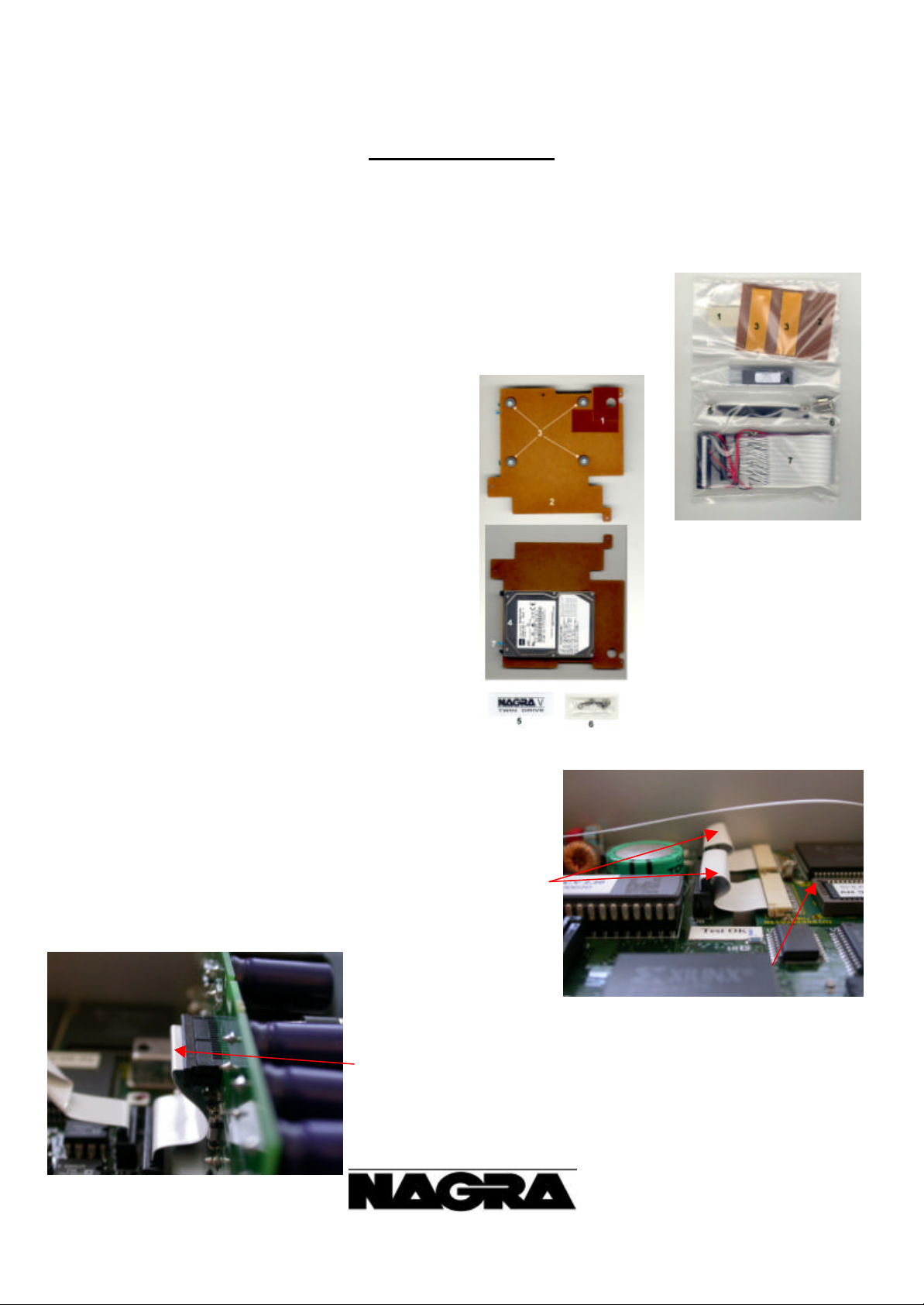
Twin drive kit P/N 7131 115 000
Parts: Description Qty
Part I
1) 4289 004 616 Linen single sided glue tape (fixed on a plastic bag)
2) 0131 030 009 Insulator for PC104 1
3) 4289 055 733 Double-sided glue tape (premounted)
4) 9131 300 020 Eprom V3.00 or higher 1
5) 0131 030 008 EDI cable guide 1
6) 3606 320 100 Spacer nut 10 mm 8
7) 8131 405 000 EDI ribbon cable 1
Part 2 (7031 162 000) Partially pre-mounted
1) 0131 030 010 Insulator for coil 1
2) 0131 030 007 HDD support 1
3) 3831 400 116 Alpha-Gel suspension 4
3251 043 034 Shim D 4.3 mm 4
3000 301 004 Screw M3 10mm Cyl. 4
4) 2097 238 000 HDD 60 GB 1
5) 0131 030 006 Twin drive label 1
6) 3606 320 050 Spacer nut 5 mm 3
3311 102 036 Spring loaded shim 2.2 mm 4
3000 200 404 Screw M2 4 mm Cyl. 1
7) 4020 420 060 Jumper for HDD 1
Procedure:
Preparation
Before installing the internal HDD, a few modifications need to be
made, this to secure the NAGRA -V before the machine is closed once
the option is installed.
Bend to 2 ribbon cables of the Time Code option (if installed) as close
as possible to the bottom of the Nagra-V. This to prevent that they
would be smashed by the internal HDD option.
For the same reason, bend the ribbon cable between the box motherboard
and the LF output PCB as close as possible to the LF output PCB.
KUDELSKI GROUP
NAGRAVISION
CH-1033-CHESEAUX
TEL 021/732-0101 1
FAX 021/732-0100
JUN 2004 ELECTRONIC SERVICE BULLETIN TIE 31-08
2 layers
2
layers
Move the camera return cable so that it sits downward to the bottom
of the machine and as most as possible behind the LF output PCB.
Reduce the pin size to maximum 1 mm versus the LF output PCB. Add
some solder to remove any sharp edges.
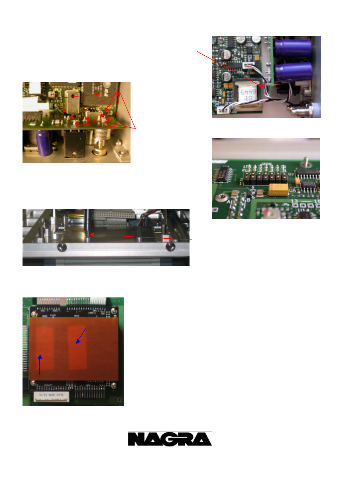
If on the upper deck
motherboard, the connector J2 is installed, cut all the pins as short as
possible or unsolder the connector. Disconnect the speaker connector.
By removing 10 nuts and 1 screw, remove the upper deck motherboard by
also removing the EDI ribbon cable from the PC104 PCB and the external
HDD as well as the HDD power connector.
On the deck, remove the left 10 mm spacer this
to install afterwards easily the ribbon cable.
Installation
By using double-sided glue tape, add the insulator (0131 030 009) on the
PC104 PCB
KUDELSKI GROUP
NAGRAVISION
CH-1033-CHESEAUX
TEL 021/732-0101 2
FAX 021/732-0100
 Loading...