

Page 1
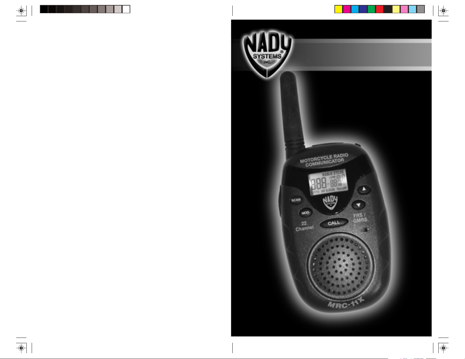
MRC-11X
Motorcycle Radio Communicator
OWNER’S MANUAL
Page 2

CONTENTS
Introduction and General Description ......................................................................... 3
Advanced Features Summary.....................................................................................4
Standard Features Summary ......................................................................................4
Warnings ..................................................................................................................... 4
To Be Safe ................................................................................................................... 5
Care and Maintenance ................................................................................................ 6
Exposure to Radio Frequency Energy ........................................................................ 6
Included and Optional Accessories ............................................................................ 7
Installing Batteries ...................................................................................................... 7
Recharging Ni-CAD or Ni-MH Batteries ..................................................................... 8
A Quick Look at Your Radio ........................................................................................ 9
Controls .................................................................................................................... 10
LCD Display Description ...........................................................................................11
Low Batteries Power Indication ................................................................................ 12
Using the Belt Clip .................................................................................................... 12
Using External Microphone/Speaker Headsets ........................................................ 12
Operation Manual ..................................................................................................... 13
Turning On with the PWR/SET Key ................................................................. 13
Setting Volume level with the UP and DOWN Keys........................................ 13
Receiving an Incoming Call (Standby Mode) .................................................. 13
Transmitting a Signal Using the PTT Key ....................................................... 13
Calling Another Party with the CALL Key ....................................................... 13
Dual Channels Receiver and Transmit (Dual Watch Mode) ............................ 13
Radio & Intercom/Intercom ............................................................................. 14
VOX (voice-activated hands-free operation) ................................................... 14
Key Lock ......................................................................................................... 14
Scan (Auto Monitor) ........................................................................................ 14
CTCSS code set ............................................................................................. 15
Auto Squelch .................................................................................................. 15
Stopwatch ....................................................................................................... 15
AUD (Stereo Auxiliary Audio Input) Jack ........................................................ 15
Driver / Passenger + charger jacks with external PTT .................................... 15
Setting Functions ............................................................................................16
Setting Calling Tone Type ............................................................................... 17
Optimizing Range ........................................................................................... 17
General Specifications .............................................................................................. 18
Troubleshooting ........................................................................................................ 19
CTCSS Codes ........................................................................................................... 20
FRS / GMRS 22 Channel Chart ................................................................................ 20
Channel Cross Reference Chart ............................................................................... 21
Licensing Information ............................................................................................... 22
Service ...................................................................................................................... 22
Navigating Menu .......................................................................................................23
Call Tone Setting ....................................................................................................... 23
INTRODUCTION AND GENERAL DESCRIPTION
Introduction:
Congratulations for your purchase of the MRC-11X bike-to-bike radio communicator
with driver/passenger intercom. Designed with special features for motorcycle,
snowmobile and other helmet/hard hat applications, the Nady MRC-11X offers the
most advanced portable communication technology available to allow you to stay
connected on the road. Offering several times the range of previous generation
motorcycle communicators, the MRC-11X provides maximum clarity and effortless
communication in the real world of motorcycle riding environments. Because the
MRC-11X operates with higher power on the special new uncluttered UHF FRS/
GMRS (U.S.) frequencies, you can now speak with another cyclist up to 7 miles away
(depending on the terrain) without interference.
Welcome to the next generation of personal communication: FRS & GMRS.
The FCC (Federal Communication Commission) has created 14 license free
frequency bands, or channels, called Family Radio Service (FRS) frequencies, and 15
licensed channels for General Mobile Radio Service (GMRS). These channels are in
the UHF (Ultra High Frequency) band, which virtually assures crystal clear reception
even in crowded noisy environments. This two-way, short-range voice radio service
lets families and groups keep in touch with each other on specific service channels.
The MRC-11X is compatible with other brands utilizing the same frequency band
(operating in the frequency range from 462.563MHz to 467.713MHz).
General Description:
Your MRC-11X includes a basic FRS and GMRS radio with 38 CTCSS tones and 22
channels (FRS & GMRS-7 channels FRS only, 8 channels GMRS only, & 7 channels
shared GMRS/FRS frequencies), and crystal clear communication range of up to 7
miles on the GMRS only channels. It provides excellent communication range and
voice quality, and user-friendly features. With special features for use with
motorcycles, the MRC-11X is designed to maximize your on-the-road
communications. The two-way radio can be voice-operated by either the driver or
passenger (VOX) or operated manually by either a remote PTT button mounted on
the handlebar or the large push-to-talk button (PTT) on the unit. The radio operates
simplex (one-way-at-a-time) mode for use by any number of riders on separate
motorcycles. The deriver/passenger intercom is full duplex (simultaneous two-way).
Auxiliary stereo input allows you and your passenger to listen to CD, tape players, or
other external music sources.
To assure the maximum performance of your unit, read these instructions
carefully and retain them for future reference.
2
3
Page 3

ADVANCED FEATURES SUMMARY
• FRS, GMRS, & shared FRS/GMRS (22 channels total / 462-467MHz)
• Choice of 6 distinct Call tones for calling each of 6 other parties individually
• 38 CTCSS privacy (lockout) tones
• VOX (hands-free) transmission with 4-level sensitivity adjust user selectable for
optimizing accurate triggering with varying background noise
• Driver/Passenger Full duplex intercom (Simultaneous two-way)
• AUX. (Stereo Audio Input)
• Two-level transmit power automatically selected:
FRS channels: Low=0.5W, up to 2 mile range
GMRS channels: High=3.0W, up to 7 mile range
• Software Set key for all controls
• Auto dual channel monitoring (receive and transmit)
• Special noise reduction circuitry for quieter operation
• Stopwatch
STANDARD FEATURES SUMMARY
• Battery power low indication on LCD
• Six-level digital speaker volume select
• Auto squelch
• Auto Scan and Manual Monitor
• Power on beep tone
• Beep tone for confirmation of key
• Key lock on/off selectable
• Back light LCD with 18 function
readout
• Dual channel or basic channel
selectable
• Max 1.3 Minute per time for transmit (for
Protect)
• Page / Calling button
• Monitor / Scan button
• Internal EEPROM for automatically
saving data entered
• Auto save of last settings when unit is
shut off
• All channels can store different CTCSS
code.
• Auto power save (standby mode)
WARNINGS
• While this unit has been designed for ruggedness, it is a precision piece of
electronic equipment that should not be exposed to water or handled carelessly.
Normal care should result in years of trouble-free operation.
• Do not leave batteries installed over a long period of time as leakage may occur,
which can destroy the unit. All batteries can cause property damage and/or bodily
injury, such as burns, if conductive material such as jewelry, keys or beaded chains
touch exposed terminals. The material may complete an electrical circuit (short
circuit) and become quite hot. Exercise care in handling any charged battery,
particularly when placing it inside a pocket, purse or other container with metal
objects.
• The antenna is permanently attached to the unit. Never attempt to remove it. Do
not use any unit that has a damaged antenna. If a damaged antenna comes in
contact with the skin, It may cause a minor burn.
• For vehicles with an air bag: Do not place your unit in the area over an air bag or in
the airbag deployment area. Air bags inflate with great force. If a unit is placed in
the air bag deployment area and the air bag inflates, the unit may be propelled with
great force and cause serious injury to the occupants of the vehicle.
WARNINGS
• Potentially Explosive Atmospheres: Turn your unit OFF when in any area with a
potentially explosive atmosphere, such as at a gasoline station filling area. Sparks
in such areas could cause an explosion or fire, resulting in bodily injury or even
death. Do not replace or charge batteries in a potentially explosive atmosphere.
Contact sparking may occur while installing or removing batteries and cause an
explosion. NOTE: Areas with potentially explosive atmospheres are often but not
always, clearly marked. They include fueling areas such as below deck on boats,
fuel or chemical transfer or storage facilities: areas where the air contains chemicals
or particles, such as grain, dust, or metal powders: and any other area where you
would normally be advised to turn off your vehicle engine.
• Blasting Areas: To avoid possible interference with blasting operations, turn your
unit OFF near electrical blasting caps or in a blasting area or in areas posted. Obey
all signs and instructions.
• Never connect this unit to more than 7.5 volts as will seriously damage the unit and
void the warranty. Never, for example, attempt to hook up external power to the
CHG (charger) power input from the motorcycle’s cigarette lighter or other source of
12V. You cannot operate the unit on external power.
• Do not open your radio to make any internal adjustments. Your radio is set up to
transmit a regulated signal on one of the 22 assigned frequencies (FRS/GMRS). It is
against the law to alter or adjust the setting inside the radio to exceed those
limitations. Any adjustment to your radio must be made by a qualified technician
using the proper test equipment. Note that such tampering will void the warranty.
• Always save your receipt as you will need it to establish proof-of-purchase date if
your unit ever needs service under the warranty.
TO BE SAFE
Never open your radio’s case. Modifying or tampering with the radio’s internal
components can cause a malfunction and invalidate its warranty and void your FCC
authorization to operate it. If your radio it not performing as it should, call the NADY
Service department (see page 22).
Never change or replace anything in your radio except the batteries
Your radio might cause TV or radio interference even when it is operating properly. To
determine whether your radio is causing the interference, turn it off. If the interference
goes away, your radio is causing it. Eliminate the interference by moving your radio
away from the receiver.
If you cannot eliminate the interference, the FCC requires that you stop using the
radio.
This device complies with part 15 of the FCC Rules. Operation is subject to the
following two conditions:
• This device may not cause harmful interference.
• This device must accept any interference received, including interference that may
cause undesired operation.
4
5
Page 4

EXPOSURE TO RADIO FREQUENCY ENERGY
The design of your MRC-11X, which generates radio frequency (RF) electromagnetic
energy (EME), complies with the following national and international standards and
guidelines.
• FCC Report and Order FCC 96- 326 ( August, 1996)
• American National Standards Institute ( C95- 1- 1992)
• National Council on Radiation Protection and Measurements (NCRP - 1986 )
• International Commission on Non- lonizing Radiation Protection ( ICNRP - 1986)
To ensure optimal unit performance and to ensure that exposure to RF energy is
within the guidelines in the above standards, the following operating procedures
should be observed:
For Portable Two-Way Communicators
• When transmitting with a handheld MRC-11X, hold the unit in a vertical position
with its microphone 1 to 2 inches ( 2. 5 to 5.0 cm ) away from your mouth. Keep the
antenna at least 1 inch (2.5cm) from your head and body.
• If you wear the unit on your body, ensure that the antenna is at least one inch
(2.5cm) from your body when transmitting.
Electromagnetic Interference/ Compatibility
Nearly every electronic device is susceptible to electromagnetic interference
(EMI) of inadequately shielded, designed or otherwise configured for electromagnetic
compatibility.
• Turn your unit OFF in any facilities where posted notices instruct you to do so.
Hospitals or health care facilities may be using equipment that is sensitive to
external RF energy.
• Turn your unit OFF when on board an aircraft when instructed to do so. Any use of
the unit must be in accordance with airline regulations or crew instructions.
CARE AND MAINTENANCE
To enjoy your radio for a long time:
• Keep the radio dry. If the unit gets wet, turn it off and remove the batteries
immediately. Dry the battery compartment with a soft cloth to minimize potential
water damage. Leave cover off the battery compartment overnight or until
completely dry. Do not use the unit until completely dry.
• Use and store the radio only in normal temperature environments.
• Handle the radio gently and carefully. Do not drop it.
• Keep the radio away from dust and dirt.
• Wipe the radio with a damp cloth occasionally to keep it looking new.
• Don’t use cleaners or solvents on the unit; they can harm the case and leak inside,
causing permanent damage. Battery contacts may be wiped with a dry, lint- free
cloth.
6
INCLUDED AND OPTIONAL ACCESSORIES
The following is included in each package:
• MRC-11X Motorcycle Communicator
• MHS-11XO premium open-face helmet-mount headset with microphone for driver
and ext. PTT button
• User Manual
• Warranty Card
• Optional Accessories Ordering Form
The following are optional accessories (see also included Optional Accessories
Ordering Form):
• MHS-11XO premium open-face helmet-mount headset with microphone for driver
or passenger and ext. PTT button
• MHS-11XC premium closed-face helmet-mount headset with microphone for
driver or passenger and ext. PTT button
• MO-1 standard open-face helmet-mount headset with microphone for passenger
• MC-1 standard closed-face helmet-mount headset with microphone for driver or
passenger
• BC-11X battery charger (for 100-240V ~ 50/60Hz input) for internally charging the
MRC-11X batteries (plugs into the PSG/CHG jack)
INSTALLING BATTERIES
Your radio requires four AAA alkaline or NiCad or NiMH Rechargeable batteries for
power. For the best performance and longest life, please note the following cautions:
• Use only fresh batteries of the
required size and recommended
type.
• Do not mix old and new batteries,
different type of batteries (alkaline
or rechargeable), or rechargeable
batteries of different capacity.
• Follow these steps to install
batteries.
1) Turn off the radio. Remove belt
clip and slide off the battery
compartment cover.
2) Install four AAA batteries
according to the polarity symbols
(+ and -) marked inside.
3) Replace the cover and belt clip.
Note:
1) Dispose of old batteries promptly and properly. Do not burn them.
2) If you do not plan to use the unit for a month or longer, remove the batteries.
Batteries can leak chemicals that can destroy electronic parts. The warranty does not
cover damage caused by leaking batteries.
7
Page 5

RECHARGING NI-CAD OR NI-MH BATTERIES
See Low Batteries Power Indication section on page 12, for instructions for
determining when batteries are low.
Warning:
• Do not attempt to charge alkaline batteries. Non-rechargeable batteries can get
hot or explode if you try to recharge them. Never attempt to charge non-
rechargeable batteries.
• If you use rechargeable Ni-CAD or Ni-MH batteries, you can recharge them
between uses externally in any appropriate commercially available charger or
you can recharge them internally (in the unit) using the optional BC-11X adapter
(see Optional Accessories Ordering Form included).
Please note: (1) Do not attempt to use any other adapter than the optional
BC-11X for charging the batteries as they can damage the unit. (2) You cannot
power the unit with the optional BC-11X as the unit can only be powered for
operation with the internal batteries.
• Internally charging the batteries with the optional BC-11X charger:
1) Use the PWR/SET button to turn off the MRC-11X (the unit can not be charged
when it is on)
2) Slide off the battery compartment cover, and install the batteries.
3) Connect the charger’s RS (Ring-Sleeve) plug to the radio’s PSG/CHG jack and
plug its other end to a standard AC outlet.
4) A complete charge takes about 7 hours.
A QUICK LOOK AT YOUR RADIO
1
23
15
13
14
12
4
5
6
7
(Note: do not charge for longer periods as overcharging can damage the batteries)
8
10
11
1. Antenna
2. DRV (driver headset) jack
3. PSG/CHG (passenger headset/internal charging) jack
4. PWR/SET (on-off/mode selected set) button (key)
5. LCD display
6. AUX (auxiliary music source input) jack
7. UP/DOWN (select) buttons (keys)
8. Internal microphone
9. Internal speaker
10. CALL button (key)
11. Battery compartment (on back)
12. MOD (mode select) button (key)
13. SCAN (scan/monitor select) button (key)
14. PTT (push-to-talk) button (key)
15. TX (Transmit) LED indicator
9
8
9
Page 6

CONTROLS
LCD DISPLAY DESCRIPTION
• PWR/SET key
1. Press and hold key for over 3 seconds to turn the power on/off
2. Press momentarily to set data selected and to exit to standby after setting mode
• DOWN key
1. Press key momentarily to set channel when in the channel set mode
2. Press and hold key for over 2 seconds in standby to turn VOX on/off
3. Press key momentarily in standby to turn volume level down
• UP key
1. Press key momentarily to set channel when in the channel set mode
2. Press and hold key for over 2 seconds in standby to set key lock or key unlock
3. Press key momentarily in standby to turn volume level up
• PTT key
Press and hold to transmit (talk)
• CALL key
1. Press momentarily in standby to call other parties with preset call tone in standby
2. Press and hold for over 2 seconds in standby to switch into stopwatch mode
• SCAN key
1. Press momentarily in standby to defeat autosquelch for monitoring
2. Press and hold in standby for 2 seconds to auto scan all channels
• MODE key
1. Press and hold key in standby for over 2 seconds to enter set mode.
2. Press key in set mode to select the next mode.
• BACK-LIGHT will turn on if any keys are pressed and turn off 5 seconds after
pressing the last key
Note: If you already have experience in operating such radios, after familiarizing
yourself with the controls of the MRC-11X you may wish to just go directly to the
Navigation Menu on page 23.
A
F H
E
G
B
I
J
C M L K
D
A) Channel Number. Changes from 1 to 22 as selected by user.
B) Displays either an L (for FRS low power mode) or an H (for GMRS high
power mode).
C) Battery power level indicator. Displays the current battery level charge.
D) Displays the current CTCSS code.
E) RADIO ON indicator
F) Key Lock ON indicator
G) Transmit mode, Receive mode indicators
H) CTCSS ON indicator
I) Volume level indicator. Changes from 1 to 6 as selected by user.
J) Dual Watch monitoring mode (dual channel)
K) Voice level sensitivity indicator for VOX hands-free operation. Displays the current
VOX level selected (1-4).
L) Basic Channel Mode indicator
M) Displays “INT” when in intercom mode
DISPLAY DESCRIPTION
Key lock ON
10
Transmit mode
Battery power level indicator
Intercom
Basic channel mode
Voice level for VOX hand-free
Dual channel mode
CTCSS on
RADIO mode
Stopwatch mode: for minute of clock
FRS mode: for channel number
Receive mode
for second of clock, for mil-second
for CTCSS number
11
Page 7

LOW BATTERIES POWER INDICATION
As you use the unit, the battery icon’s elements will disappear
one by one to show the remaining power. When only one
element remains, replace alkaline batteries or recharge NiCad or
Ni-MH batteries as soon as possible.
USING THE BELT CLIP
To use the supplied belt clip, insert the clip fully
into the slot at the back of the radio unit. To
remove the clip, press the top of the clip and slide
it out. The belt clip needs to be removed before
changing/installing the batteries for full access to
the battery compartment.
USING EXTERNAL MICROPHONE/SPEAKER
HEADSETS
The MRC-11X is supplied with an MHS-11XO headset for the driver. If the unit will
also be used for driver/passenger communications, an optional second headset can
be purchased for the passenger (see the Optional Accessories Ordering Form
enclosed for more info re the choice of the premium MHS-11XC/O or the standard
MO-1/MC-1 headsets). When the driver headset is plugged into the DRV jack on the
unit’s top panel, it automatically disables the MRC-11X’s built-in Mic and speaker,
and the headset must be used for all communication.
(Note: Always make sure the unit is off or the volume at minimum before plugging in
the headsets and placing them on the head.)
LOW BATTERIES POWER INDICATIONOPERATION MANUAL
Turning On with the PWR/SET Key
Press and hold the PWR/SET key for over 3 seconds to turn the unit on/off. The unit
will “beep” when turning the unit on/off and the LCD screen will light when unit is on.
Setting Volume level with the UP and DOWN Keys
Press either the UP or DOWN keys once momentarily to enter volume setting mode.
Press the UP key or DOWN key again to increase or decrease volume level from 1 to
6 as shown on the volume icon of the LCD display. Press the PWR/SET key
momentarily to set or it will automatically set in 15 seconds. A beep will sound to
confirm this setting.
Receiving an Incoming Call (Standby Mode)
In standby mode (not programming or selecting functions), the unit automatically will
receive incoming calls from any other unit on the same channel and CTCSS code
whenever you are not talking/transmitting. When you receive a signal, the ( ) icon
appears on the display.
Transmitting a Signal Using the PTT Key
Check the channel activity by pressing and holding the SCAN button. You will hear
static if the channel is unoccupied. Do not TRANSMIT if someone is talking on the
channel. Press and hold the PTT button to TRANSMIT. The ( ) icon is displayed. The
TX LED indicator will light up in red. Hold the unit in a vertical position with the
MICROPHONE 1 to 2 inches from the mouth. While holding the PTT button, speak
into the unit using a normal tone of voice. Release the PTT button when you have
finished transmitting. The automatic end-of-message “Roger” tone will sound and
you can then listen for another party’s response.
NOTE: In order for other people to receive your transmission, they must also be on
the same channel you are currently using. Refer to the Changing Channels section for
more information.
MHS-11XC
MHS-11XO
12
MO-1
MC-1
After you hold down the TALK key continuously for about 80 seconds, the unit will
automatically stop your transmission to save power. If necessary to continue
transmitting, wait a few seconds before proceeding.
Calling Another Party with the CALL Key
Use the CALL key to alert another party you wish to communicate with them. Both
units must be set to the same channel and CTCSS code. Momentarily press and
release the CALL key to call the other party with a 3-second calling alert tone. Wait
for the party’s response or proceed to “Talking to Another Party using the PTT Key”.
See pg. 17 for instructions on how to select one of 6 different call tones for individual
paging when using your unit with a group. You can also use the CALL Tones to signal
the beginning or the end of a transmission.
Dual Channels Receiver and Transmit (Dual Watch Mode)
Dual channels reception: If the dual channels setting is OFF, the ( ) icon
appears on the display and you only have the basic single channel reception. If the
13
Page 8

OPERATION MANUAL
LOW BATTERIES POWER INDICATIONOPERATION MANUAL
dual channels setting is selected ON, the ( ) icon appears on the display and the
unit will receive one either of the dual channel selected (basic channel and second
channel). This Dual Watch monitor mode is especially useful when the signal you
want to hear is consistently weak
Dual channels transmission: If the dual channels in on, the ( ) icon appears on the
display and the unit can transmit on either of dual channels (basic channel and
second channel). Hold down the TALK key to the transmit on the basic channel, and
press and release the MODE key and then hold down the TALK key to transmit on the
second channel (the second channel number will then appear on the display).
Radio & Intercom / Intercom
Intercom only: In the Intercom mode ( ) icon, insert the driver and passenger
headsets into the appropriate jacks on the top panel as marked on the rubber cover
plug. The driver and the passenger can then communicate with each other
simultaneously (full duplex).
Radio & intercom: In the Radio & Intercom mode ( ) icon, when the driver and
the passenger headsets are connected, the unit will automatically also be in the
Intercom mode. Both headsets will hear any received audio and both of the
microphones are able to transmit audio and trigger the VOX.
VOX (voice-activated hands-free operation)
In standby mode, press and hold the DOWN key for over 2 seconds to turn the VOX
on/off. The VOX ( ) icon appears on the display whenever the VOX mode is
turned on. To optimize the VOX operation, you can select 1 of 4 different input volume
levels for triggering the VOX, depending on the background ambient noise and your
speaking level. See “ Setting Functions”, pg. 16, for instructions for choosing the
VOX level desired.
Key Lock
The purpose of the Lock function is to lock most keys to avoid accidental operation.
In standby mode, press and hold the UP key for over 2 seconds to turn on the key
lock. The ( ) icon appears on the display. Press and hold the UP key again to turn
off the key lock. While the unit is set to the key lock status, only the TALK, UP and
SCAN keys will have any response.
Scan (Auto Monitor)
Auto Monitor: When the signal you want to hear is consistently weak, you may place
the radio in monitor mode, which will defeat the auto squelch, and thus prevent the
muting of weak signals. However, between receptions you will then also hear the
normal loud radio hiss, since the auto squelch is off. Press the SCAN key
momentarily to enter monitor mode. To return to normal operation, press any key. See
also “ Auto Squelch”.
Scan: Press and hold SCAN key for over 2 seconds to start scanning all the channels
in the up direction. To exit the scan mode and select the channel being displayed at
any point to be the basic channel, press any other key.
CTCSS code set
You can select any one of the 38 available CTCSS privacy (lockout) codes for each of
the 22 channels while the CTCSS icon is flashing. See pg. 16, “ Setting Functions” for
instructions for how to enter CTCSS Select mode to get CTCSS icon to flash. Press
the UP or DOWN key to select the desired code number for that channel. Press the
MOD key again to save the CTCSS number selected. Press the PWR/SET key
momentarily to exit.
Auto Squelch
This unit is equipped with an auto squelch that we’ll automatically shut off weak
transmissions and unwanted noise due to terrain conditions or if you reach the
operating range limit. It can be defeated (turned off) by pressing the SCAN key. See
also “Scan (Auto Monitoring) pg 14.
Stopwatch
To enter the stopwatch mode, press and hold the CALL key for over 2 seconds.
In stopwatch mode, press the TALK key to start count, and press the TALK key again
to stop. While the watch is stopped, press the CALL key to reset the counter, press
the TALK key to restart the watch. To freeze the LCD display while counting, press the
CALL key once momentarily. To pick up the current count, press the CALL key once
again momentarily. Press any of the other keys to exit stopwatch mode at any time
and set the unit into standby mode.
AUX (Stereo Auxiliary Audio Input) Jack
A tape player, radio or CD (or any other external music source) can be connected to
the AUX (Auxiliary In) stereo jack to allow both the driver and passenger (if any) to
also hear music while either conversing with each other or with other bikes. This
function works in any mode, and the AUX audio will not be transmitted or heard by
the other parties you are communicating with. The audio level heard needs to be
adjusted with the volume adjust knob of the music source.
Driver / Passenger + charger jacks with external PTT
The MRC-11X is specially designed with DRV/PSG+CHG jacks with external PTT
(push-to-talk) capability. Both the DRV and PSG jacks accept the MHS-11X (C or O)
headset/microphone for motorcycle, with external PTT mounting on the handlebar
(one headset is supplied with the unit). If the unit will also be used for driver/
passenger communications, an optional MO-1 or MC-1 headset for the PSG jack is
needed (see the enclosed Optional Ordering Form for Accessories). When the driver
headset is plugged into the DRV jack on the unit’s top panel, it automatically disables
the MRC-11X’s built-in Mic and speaker, and the headset must be used for all
communication. The PSG jack also accepts the external optional BC-11X battery
charger to charge the Ni-CAD or Ni-MH rechargeable batteries internally. For charging
instruction see pg. 8, “Recharging Ni-CAD or Ni-MH Batteries”.
14
15
Page 9

OPERATION MANUAL
Setting Functions
For all the function set modes:
• Press the MODE key to save the set number selected and enter the next set mode.
Press the PWR/SET key to save the set number and exit the set mode. Press the UP
key or DOWN key to change the set number or status. Press any other keys to exit
the set mode.
• While the unit is in standby mode, press the MOD key for 2 seconds (till unit beeps)
to enter the set mode. This allows a choice of seven different sequential modes to
set: (1) Basic channel select, (2) Basic CTCSS code number selected, (3) VOX level
select, (4) Dual channel scan, (5) Second channel select, (6) Second CTCSS code
number select, (7) Radio/Intercom or Intercom select. Press PWR/SET key anytime to
set selection and return to standby mode.
OPERATION MANUAL
Setting Calling Tone Type
When the unit is off, press and hold the PWR/SET key and the SCAN key
simultaneously till the unit beeps. The unit’s full LCD display, showing all icons, will
light up. You can now select the call tone type.
Press the CALL key to sound the first choice of 6 different call tones available. You
can either press the CALL button again in sequence to select and sound the other
available tones or scroll through them all with the UP and DOWN buttons. When you
have the call you wish to transmit selected, press either the MOD or the SET key to
save. This tone will now be transmitted whenever you press the CALL button in
standby mode until you select another tone. Press SET key again to turn the power
off.
• (1) Basic channel select: While the unit in set mode, press the UP key to increase
the channel, press the DOWN key to decrease the channel. Press the MODE key
momentarily (unit will beep) to save the selected basic channel and to set the CTCSS
code for the basic channel selected.
• (2) Basic CTCSS code number selected: Press the DOWN key or the UP key to
change the CTCSS code. Press the MODE key again to save the CTCSS number
selected and to set the VOX level.
• (3) VOX level select: Press the UP key or the DOWN key to select one of the 4
different VOX sensitivity levels. Press the MODE key to save the VOX level selected
and to set the dual channel mode on or off.
• (4) Dual channel scan: Press either the UP or the DOWN key to turn the dual
channel scan on or off. Press the MODE key to save channel status and enter next
mode. When the dual channel mode is set to on, and the ( ) icon is displayed, you
can set the second channel. When the dual channel scan is set to off, proceed to (7)
Radio/Intercom mode.
• (5) Second channel select: Press the UP or DOWN key to select the channel and
the MODE key again to save the second channel and to set the second channel
CTCSS code.
• (6) Second CTCSS code number select: Press the UP or DOWN key to select the
CTCSS code and the MODE key again to save second channel CTCSS code and to
set the Radio/Intercom on/off.
• (7) Radio/Intercom or Intercom select: Press either the UP or DOWN key to
select between Radio/Intercom (both and icons displayed) or intercom (
icon) only. Press either the MODE or PWR/SET key again to save all status and exit
set mode back to standby.
See also the section Call Tone Setting in the Navigating Menu, page 23
Optimizing Range
Your MRC-11X radio has a range of up to 2 miles for 0.5 watts, up to 7 miles for 3.0
watts under the most ideal conditions such as wide, open flat terrain. This effective
range can be shortened by signal attenuation caused by buildings, vehicles, and
other obstructions such as dense foliage and hilly terrain.
• UHF operation allows the MRC-11X to provide communication that is virtually free
of the atmospheric interference that is often common with lower frequency bands.
Additionally, higher power and an antenna system that is very efficient as compared
to other unlicensed radio bands (such as 49MHz) often used for motorcycle
communicators, further enable the farther operating range of the MRC-11X.
• Often the limits to maximum possible range are environment factors such as
blockage caused by trees, buildings, hills or other obstructions. Sometimes you may
find communication suddenly not possible (localized dropout zone), and this can
almost always be overcome by moving only a few feet to a new location. Be aware
that the range may be greatly reduced while operating in a vehicle or metal building.
• Battery condition also effects range, with fresher batteries providing greater
transmitted output power. The MRC-11X operates on rechargeable Ni-CAD or Ni-MH
batteries or ordinary alkaline batteries.
• Since the body absorbs some radiated energy, thus reducing range, note that
holding the unit in your hand, or mounting it on your bike’s handlebars (so the unit is
away from your body) will ultimately maximize range under all conditions. However,
normal mounting on your belt or clothing is often more convenient and should
provide sufficient range for most bike-to-bike communications. If maximum range is
needed, experiment with the unit placement for best performance.
Note: This unit cannot ensure privacy in communications.
16
17
Page 10

GENERAL SPECIFICATIONS
TROUBLESHOOTING
Operating Frequency Range ............................................... 462.563MHz-467.713MHz
Number of Channels ........................................................... 22 total/GMRS + FRS
Effective Radiated Power ................................................... GMRS channels: 3W @ 6.0VDC
FRS channels: 500mW @ 6.0VDC
(power automatically selected for
channels as required by FCC)
Range .................................................................................. Up to 7 miles (11Km) line-of-sight,
3/4 to 2 miles typical
Modulation .......................................................................... FM, +/-1.5kHz
Carrier Frequency stability .................................................. +/- 2PPM
Harmonic Suppression ....................................................... >50dB
Carrier Attack Time ............................................................. 30ms
Receiver I.F. Frequencies .................................................... 1st: 21.6MHz, 2nd: 455KHz
Receiver Sensitivity (12 dB Sinad) ...................................... 0.4uV
Receiver Selectivity ............................................................. 50dB
Max S/N ratio @-60dBm RF input ...................................... 50dB
Squelch sensitivity .............................................................. -118dBm
Attack time ..........................................................................120ms
Closing time ........................................................................ 200ms
Nominal Audio Output ........................................................ 200mW
Audio Frequency Response ................................................ 300-3000Hz
Audio distortion .................................................................. <1% (@1KHz deviation and 1mV RF input)
Max. Audio Output @10% THD .......................................... 350mW
Internal Speaker (deactivated when using headset) ........... 8 ohm/0.25W
Internal Microphone (deactivated when using headset) ..... Electret condenser
Microphone Sensitivity ....................................................... 10mV @ 1.5KHz deviation
Low Battery Display Threshold ........................................... 4.3-4.6VDC
Transmit Current (4.6VDC High Power) .............................. <0.8A (TX); <30mA (STBY); <100mA (RX)
Current Drain (Intercom) ..................................................... <100mA
Standby Current (4.6VDC) .................................................. <30mA
Power Required .................................................................. 4 Ni-Cad, NiMH
or Alkaline AAA batteries (4.6-6.0 VDC)
Battery Life 4.6VDC (4xAAA) ............................................... >48 HR (RX)
Max. Audio output @ 10% THD Current ............................. <200mA
Dimensions/Weight ............................................................. 2.5" X 4.0" X 1.0" (63.4 X 101.6 X 25.4mm)
5.1oz / 143g (without batteries)
SYMPTOM — No Power
SOLUTION
• Check batteries. Ensure that the batteries are installed correctly
• The batteries may be weak.
• Replace old batteries with four (4) new AAA alkaline or fully charged Ni- MH or
NiCad rechargeable batteries.
SYMPTOM — Weak Reception
SOLUTION
• Press the UP button to increase VOLUME.
• The receiving signal may be weak and/ or out of range. If this happens press the
SCAN button to defeat the AutoSquelch .
SYMPTOM — Can Not Change Channels
SOLUTION
• To change channels, press the MOD button until the Channel number flashes on the
LCD Screen. Press the UP or DOWN button to change channels.
• Batteries may be weak and need replacement. Replace with new batteries if the
BATTERY CHARGE LEVEL indicator is low.
SYMPTOM — Limited Range
SOLUTION
• Batteries may be weak and need replacement. Replace with new batteries if the
BATTERY CHARGE LEVEL indicator is low.
• The maximum range will vary depending on terrain and environment. Open fields
provide the maximum range, while structures, heavy foliage and use in buildings
and in vehicles may limit the range significantly.
• Wearing the radio close to the body, such as in a pocket or on a belt, will decrease
range. Change the location of the radio away from the body for optimum range
under any conditions.
SYMPTOM — Sound Distortion Problems
SOLUTION
• If you are transmitting, speak in a normal tone of voice, 1 to 2 inches away from the
MICROPHONE.
• If you are receiving, lower the VOLUME to a comfortable level.
• Radios may be too close. Radios must be at least 5 feet apart. Increase your
separation distance.
• Radios too far apart. Obstacles may be interfering with transmission. Shorten your
operating distance.
18
19
Page 11

CTCSS CODES
CHANNEL CROSS REFERENCE CHART
CODE NO.
10 94.8 23 146.2 36 233.6
11 97.4 24 151.4 37 241.8
12 100.0 25 156.7 38 250.3
ASSIGNMENT
FREQ (HZ)
0 No Code 13 103.5 26 162.2
1 67.0 14 107.2 27 167.9
2 71.9 15 110.9 28 173.8
3 74.4 16 114.8 29 179.9
4 77.0 17 118.8 30 186.2
5 79.7 18 123.0 31 192.8
6 82.5 19 127.0 32 203.5
7 85.4 20 131.8 33 210.7
8 88.5 21 136.5 34 218.1
9 91.5 22 141.3 35 225.7
CODE NO. CODE NO.
ASSIGNMENT
FREQ (HZ)
FRS / GMRS 22 CHANNEL CHART
NO.
1 462.563 9 467.588 17 462.600
2 462.588 10 467.613 18 462.625
3 462.613 11 467.638 19 462.650
4 462.638 12 467.663 20 462.675
5 462.663 13 467.688 21 462.700
6 462.688 14 467.713 22 462.725
7 462.713 15 462.550
8 467.563 16 462.575
FREQ (HZ)
NO.
FREQ (HZ)
NO.
ASSIGNMENT
FREQ (HZ)
FREQ (HZ)
15 CHANNEL GMRS 22 CHANNEL FRS/GMRS 14 CHANNEL FRS
111
222
333
444
555
666
777
CHANNEL NOT
AVAILABLE
11 15
816
12 17
918
13 19
10 20
14 21
15 22
88
99
10 10
11 11
12 12
13 13
14 14
CHANNEL NOT
AVAILABLE
20
21
Page 12

LICENSING INFORMATION
NAVIGATING MENU
FRS (Family Radio Service) channels operation-none required.
GMRS (General Mobile Radio Service) channels operation-requires operator
licensing, call sign etc. For further information, contact the FCC at www.fcc.gov
GMRS Licensing Eligibility: An individual 18 years of age or older, who is not a
representative of a foreign government, is eligible to apply for a GMRS system
license. Individual family members are all ages are subsequently eligible to operate
GMRS stations and units within the licensed system.
This device complies with Part 15 of the FCC rules. Operation is subject to the
following two conditions: (1) this device may not cause harmful interference, and (2)
this device must accept any interference received, including interference that mat
cause undesired operation.
SERVICE
(U.S.) Should your unit require service, please contact the Nady Service Department
via phone at (510) 652-2411 or E-mail at service@nady.com
Any installation or operating questions should be directed to our service department.
Do not return the unit to the store before calling us. We can probably help you with
one short phone call or E-mail.
(International) For service or questions, please contact the Nady MRC-11X
motorcycle accessories distributor in your country through the dealer from whom
you purchased this product.
MONITOR/
SCAN
MENUSET BACKLIGHT
VOLUME
UP/DOWN
CALL CTCSS 0-38 CODE
MONITOR/
SCAN
KEY LOCK
ON/OFF
VOX
ON/OFF
PTT CTCSS 0-38 CODE
POWER
OFF
CHANNEL 1-22 CH
VOX 1-4 LEVEL
B.SCAN DW
CHANNEL 1-22 CH
RADIO INTERCOM
22
CALL TONE SETTING
SET + SCAN
TEST
SCREEN
SET
CALL
POWER
OFF
23
1-6 TONE SET
Page 13

NADY SYSTEMS, INC.
nady.com
 Loading...