

OWNER’S MANUAL
OWNER’S MANUAL
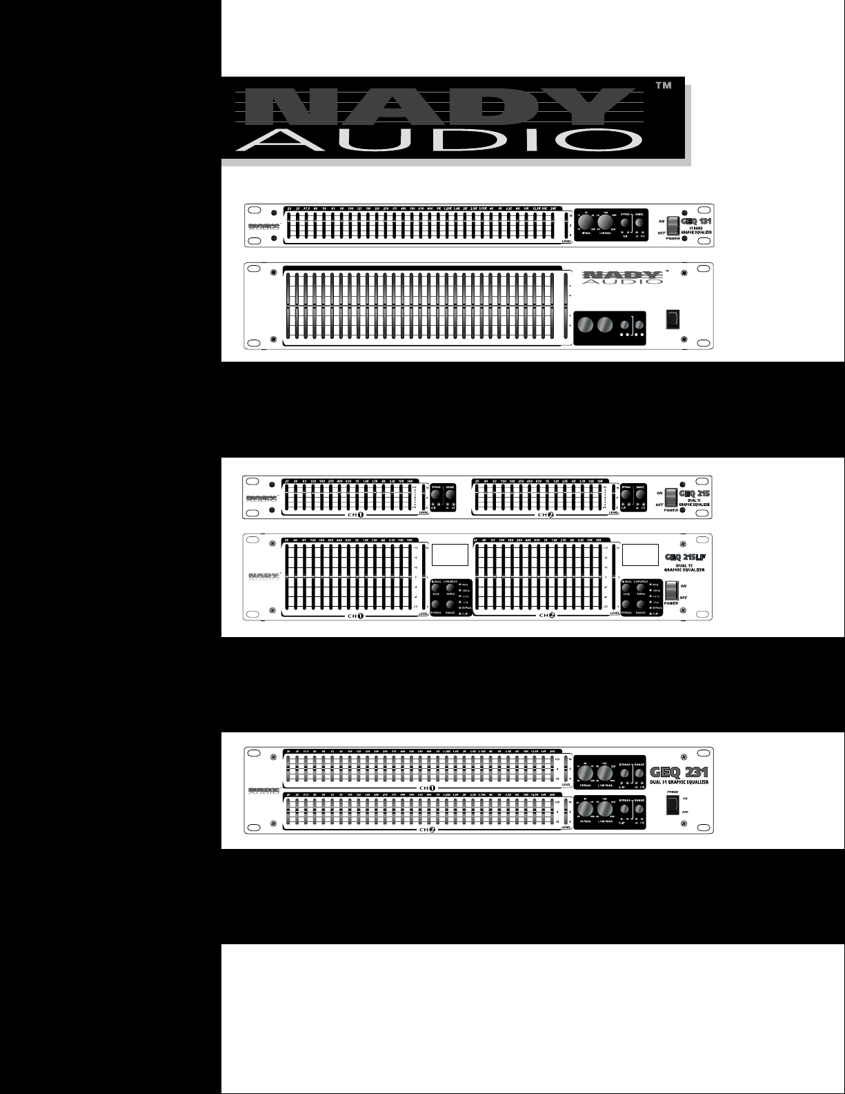
GEQ 131/ 131LF
Single Channel 31 Band Graphic Equalizer
GEQ 215/ 215LF
2 Channel 15 Band Graphic Equalizer
GEQ 231
2 Channel 31 Band Graphic Equalizer
GEQ 131LF
20 31.5 50 100 200 500 1.25K 2.5K 6.3K 12.5K25 40 80 160 400 1K 2K 5K 10K63 125 315 800250 630 1.6K 4K3.15K 8K 16K 20K
10
+12
+6
+3
5
0
40
-3
15
-6
0
-12
HI PASS
LEVEL
GEQ 131LF
31 BAND GRAPHIC EQUALIZER
15K
BYPASS
3K 50K
LOW PASS
22K7K
RANGE
CLIP –6 –12
60
25010
POWER
ON
OFF

Contents
GGEEQQ--SSeerriieess
GRAPHIC EQUALIZER SERIES
Congratulations!
You have just purchased one of the finest graphic
equalizers on the market today. This EQ was developed using the expertise of professional sound engineers and working musicians. You will find your new
NADY AUDIO EQ has superior performance and
greater flexibility than any other graphic equalizer in its
price range.
Read this manual carefully to get the most out of your
new EQ. Thanks for selecting NADY AUDIO for your
choice in graphic equalizers.
Date of Purchase__________________________
Dealer’s Name____________________________
City_____________________________________
State___________ Zip______________________
Model#__________________________________
Serial #__________________________________
FEATURES............................................................................................................................................3
WARNING..............................................................................................................................................3
INSTALLATION......................................................................................................................................4
Input/Output Connections ............................................................................................................4
Power Connection ......................................................................................................................4
Precautions..................................................................................................................................5
Signal Levels ..............................................................................................................................5
Chassis Grounding......................................................................................................................5
OPERATING INSTRUCTIONS..............................................................................................................5
FRONT P ANEL CONTROLS AND CONNECTIONS ............................................................................6
REAR PANEL CONTROLS AND CONNECTIONS ..............................................................................7
TYPICAL SET-UP..................................................................................................................................8
Sound Reinforcement Applications..............................................................................................8
Musical Instrument Application................................................................................................. ...8
Studio Applications......................................................................................................................8
SPECIFICATIONS ................................................................................................................................9
• GEQ 131: 1 Channel, Single Rack Space, 31—1/3rd Octave
Bands
• GEQ 131LF: 1 Channel, Double Rack Space, 31—1/3rd
Octave Bands, Long Throw Faders (60mm travel)
• GEQ 215: 2 Channel, Single Rack Space, 15—2/3rd Octave
Bands Each Channel
• GEQ 215LF: 2 Channel, Double Rack Space, 15—2/3rd
Octave Bands Each Channel, Long Throw Faders (60mm
travel)
• GEQ 231: 2 Channel, Double Rack Space, 31—1/3rd Octave
Bands Each Channel
• Active balanced (XLR and 1/4" TRS) and unbalanced (RCA)
input/output connectors
• Constant Q bandwidth from each filter with a 3% center
frequency accuracy
• Parallel filter design for minimal phase distortion
• Ultra low-noise circuitry
• Variable low-cut and low pass filters, 12dB/octave (GEQ 131/
131LF/GEQ 231), switchable filters (GEQ 215LF)
• Selectable range 6dB or 12dB
• Variable input level control
• Equalizer ON/OFF bypass switch
• Peak (overload threshold) LED
• Internal power supply with AC input and selectable line
voltage (110-240VAC, 50/60Hz)
• Ground lift switch
• Power off automatic bypass function
FEATURES WARNING
An equilateral triangle enclosing a
lightening flash/arrowhead symbol is
intended to alert the user to the
presence of uninsulated "dangerous
voltage" within the product’s enclosure, which may be of sufficient
magnitude to constitute a risk of
electric shock.
An equilateral triangle enclosing an
exclamation point is intended to alert
the user to the presence of
important operating and service instructions in the literature enclosed
with this unit.
CAUTION! TO REDUCE THE RISK OF FIRE, RE
PLACE ONLY WITH SAME TYPE FUSE.
ATTENTION! UTILISER UN FUSIBLE DE RECHANGE DE
MEME TYPE.
WARNING! TO REDUCE THE RISK OF FIRE OR
ELECTRIC SHOCK. DO NOT EXPOSE
THIS PRODUCT TO RAIN OR MOISTURE.
DO NOT REMOVE CHASSIS (OR BACK).
NO USER-SERVICEABLE PARTS INSIDE.
REFER SERVICING TO QUALIFIED
PERSONNEL.
3
GEQ 131/131LF
Single Channel 31 Band Graphic Equalizers
GEQ 215/215LF
2 Channel 15 Band Graphic Equalizers
GEQ 231
2 Channel 31 Band Graphic Equalizer
Graphic Equalizer GEQ Series
POWER
10
+12
+6
-6
+3
-3
0
-12
0
LEVEL
5
31 BAND GRAPHIC EQUALIZER
GEQ 131LFGEQ 131LF
OFF
ON
BYPASS
CLIP –6 –12
RANGE
40
60
15
25010
HI PASS
15K
22K7K
3K 50K
LOW PASS
20 31.5 50 100 200 500 1.25K 2.5K 6.3K 12.5K25 40 80 160 400 1K 2K 5K 10K63 125 315 800250 630 1.6K 4K3.15K 8K 16K 20K
To ensure years of enjoyment from your NADYAUDIO graphic equalizer, please read and understand
this manual thoroughly before using the unit.
These five equalizer models are each designed for
mounting in a standard 19" equipment rack or one of
the many rack type portable cases available on the
market. The units are either single rack (1.75") or
double rack (3.5") as noted. All five models are 8.66
inches deep.
Install the equalizer in a rack with the rack screws
provided. Route the A.C. power cord to a convenient
power outlet away from audio lines. The unit may be
turned on and off from the front panel power switch or
a master equipment power switch. Since the unit
draws a relatively small amount of current during idle,
the unit may be left on continuously. NADY AUDIO
equalizers do not generate an unduly large amount of
heat and do not need to be specially ventilated or
cooled. The units should not be subjected, however,
to high heat environments.
Although the unit’s chassis is shielded against radio
frequency (RF) and electromagnetic interference
(EMI), extremely high fields of RF and EMI should be
avoided.
Paralleling inputs and outputs may be accomplished
by using any of the 3 connectors.
Note: The 1/4" TRS are normally used for this
function.
INSTALLATION
4
VOLTAGE SELECTOR
Europe (except UK): 230V, 50Hz
UK and Australia: 240V, 50Hz
USA and Canada: 120V, 60 Hz
For other areas, please check with
local authorities.
If the voltage selector is not set for your area:
Confirm that the power cord is not plugged into a wall
outlet. Move the voltage selector switch with a small
screwdriver so that the marker is set to the voltage
for your area.
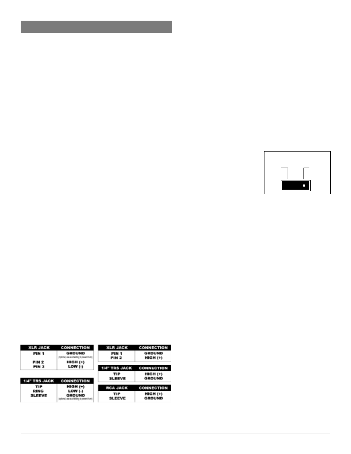
The 1/4" phone jack, RCA jack, and XLR connector
inputs and outputs can be used for balanced and
unbalanced connections. CAUTION: Using more
than one connector at a time for the INPUT/OUTPUT
pair could unbalance balanced lines, cause phase
cancellation, short a conductor to ground, or cause
damage to the other equipment connected to the
equalizer.
Input/Output Connections
For unbalanced operation,
wire the connectors as follows:
Each of these five NADY AUDIO graphic equalizers is
designed for operation from 120-240 volts, 50-60 Hz
AC supplies. Power requirements for electrical
equipment differ from area to area. In new installations and portable sound systems, or any situation in
which the AC power is in question, it is wise to
confirm the voltage and select the appropriate line
voltage switch before connecting the instrument to
power sources.
Check to see that the unit is set to the voltage for
your area by referring to the table below:
Power Connection
115V 230V
120V 240V
For balanced connection,
wire the connectors as follows:

Before starting to equalize your sound system there
is some information you should know and procedures
you should follow:
• These NADY AUDIO equalizers are equipped
with a BYPASS switch with an LED indicator. If
you disable the BYPASS switch, the LED will turn
off and all equalization settings will be restored. In
bypass mode, the audio signal will flow through
at unity gain.
• Use the range selection switch to select between
a 6db or 12dB level adjust range. The dual color
range LED will indicate green for 6dB and red for
12dB.
• The input level control allows adjustment between
OFF (center detent) and +/-6dB. Note: The unit is
equipped with a red overload LED, which
illuminates when the signal reaches 5dB prior to
clipping. It is normal for the overload LED to flash
occasionally, but if the overload LED is on steady
you must readjust the level control. Below are
some tips to follow while doing the initial set-up.
1. Set channel levels to the center detent (0dB-unity
gain) on the front panel.
2. Enable the BYPASS switch (Note: The red LED is
ON).
3. Set all slide controls to the center detent or 0dB
(unity gain) position.
4. Select the 6dB range switch (green LED ON).
5. Apply signal to the system.
6. Disable the BYPASS switch, red LED OFF.
7. If the CLIP (overload) LED is on you must turn
down the level control.
8. You may now start equalizing your system.
9. Switch the range switch to 12dB (red LED is lit) if
the 6dB range does not provide sufficient gain.
5
Precautions
Protecting yourself from electric shock:
• Never touch the plug with wet hands.
• Always pull out by the plug and never the cord.
• Only let a qualified professional repair the
equipment. An unauthorized person might touch the
internal parts and receive a serious electric shock.
• Never allow a child to put anything, especially
metal, into the equipment.
Protecting your NADY AUDIO Graphic Equalizer:
• Use only a household AC power source. Never use
a DC power source.
• If water is spilled on or in the unit, unplug it and call
for service.
• Make sure that the equipment is well ventilated and
away from direct sunlight
• Avoid damage to the internal circuits and the
external surface by keeping the unit away from
sources of high heat.
• Avoid using spray type insecticide or solvents
near the equipment. It can damage the finish an
might ignite suddenly
• To avoid damaging the finish, never use denatured
alcohol, paint thinner or other similar chemicals to
clean 6 the equipment.
• Place the unit on a flat and solid surface or in a
rack.
• To enjoy your NADYAUDIO graphic equalizer for a
long time, please read this owner’s manual
thoroughly.
Signal Levels
Signal levels from -18dBu to +18dBu are considered
normal. Do not directly connect microphones into the
equalizers. Microphones require a pre amp.
Chassis Grounding
NADY AUDIO equalizers are equipped with a rear
panel ground lift switch. If, after setting up your
system, the system exhibits excessive hum or
buzzing, the problem may be that there is a ground
incompatibility between your equalizer the other
equipment in the same system. There are several
combinations that can be attempted. Note: ALWAYS
TURN YOUR AMPLIFIERS DOWN BEFORE
CHANGING YOUR GROUNDS AROUND. Try
different combinations of lifting grounds with the
ground lift switches or make sure all chassis are
connected to earth ground, either through the A.C.
power cord ground or by the front panel rack mount
screws.
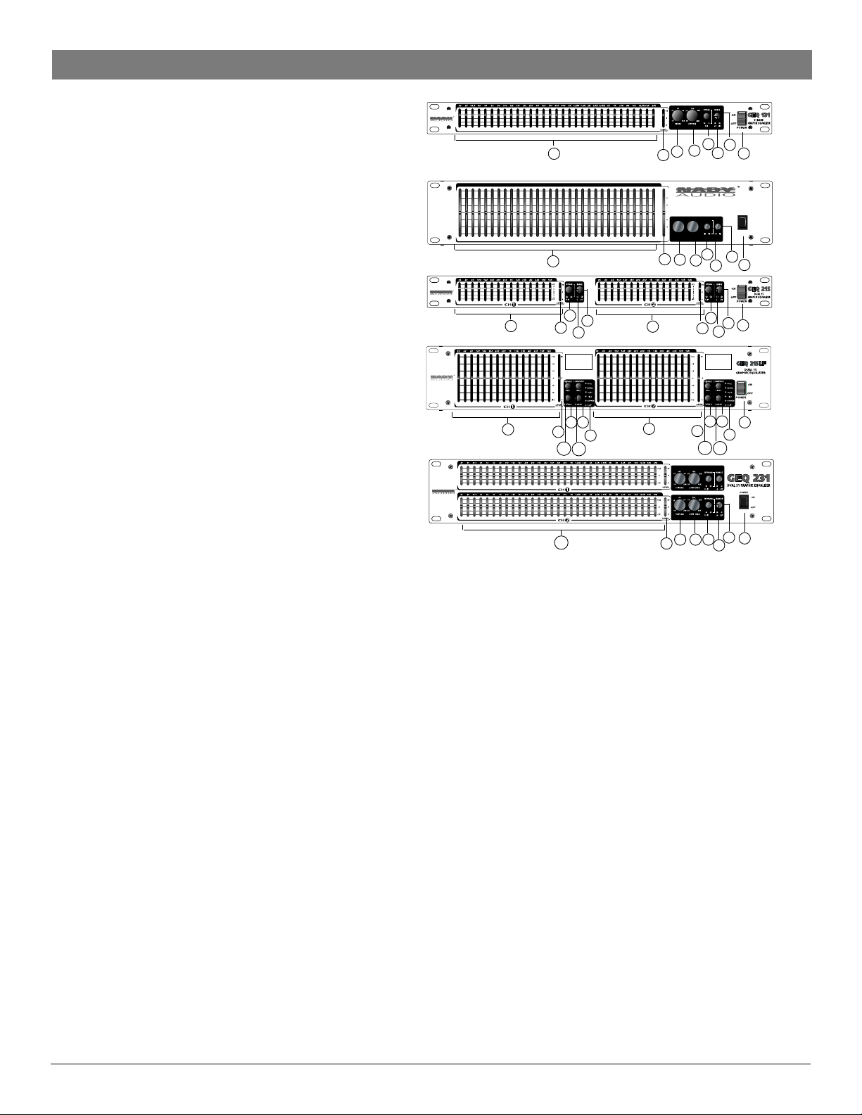
1. Power Switch
To turn the equalizer ON or OFF, press the upper or lower
portion of this button.
CAUTION: Always turn on your equalizer BEFORE your
power amplifiers are turned on, and always turn off your
equalizer AFTER your power amplifiers have been turned
off.
2. Input Level Control
This controls the level of signal to the equalizer. It is capable
of +/- 6dB of gain.
This control is used to adjust for variation in input level to the
equalizer channel, or to compensate for the equalization
applied to the input signal. Turn this control down if the CLIP
LED illuminates steady (meaning too strong an input signal).
Unity gain can be set by turning this knob to its center detent
position.
3. Low-Cut/High-Pass Filter (GEQ 131/131LF/231)
These equalizers are equipped with a 10Hz, 12dB/octave,
variable Low Cut/High-Pass Filter (HPF) to cut down unwanted
low frequency signal. Because of its high roll-off slope, the HPF
can be efficiently used to attenuate the "HUM" noise from preceding instruments, or to prevent the low frequency resonance that
can occur when speakers are installed in an enclosed acoustic
environment.
3A. High-pass Filter Switch and Indicator (GEQ 215/215LF)
40 Hz, 12dB/octave HPF. LED lights when activated.
4. Filter Range Switch & Indicators
The gain range of the filter sliders is switchable (as a group) from
+/-6dB to +/-12dB for maximum boost/cut capability. At 6dB the
green LED will illuminate and at 12 dB the red LED will illuminate.
5. In/Out Bypass Switch & Indicator
This switch inserts or removes the equalizer channel from the
signal path. The red LED lights when the switch is depressed to
indicate that the unit or channel is in the equalizing mode. In the
bypass mode, the signal is routed from the input directly to the
output. The bypass function is FET switched to prevent switching
transients when inserting the equalizer into the circuit path. Use
this switch to compare equalized and unequalized material. When
there is no power to the unit, the equalizer automatically reverts
to bypass.
6. Peak/Clip Indicator
This red LED illuminates if any section of the equalizer is within
5dB of clipping. Occasional blinking of this LED is acceptable,
but if it remains on more than intermittently you should turn down
either the equalizer’s level controls or reduce the output level of
the preceding component to avoid audible distortion.
7. Filter Level Slider Controls
Each one of these linear potentiometers will boost or cut its noted
frequency by either +/-6dB or +/-12dB depending on the filter
range selected. When all of the sliders are in center detented
position, the output of the equalizer is flat. Each slider is marked
with the center frequency of its band pass filter.
8. Low-Pass/High-Cut Filter (GEQ 131/131LF/231)
This filter rolls off higher frequencies. This is useful for reducing
hiss or sibilance from a signal. Its range is adjustable from 3KHz
to 50KHz.from 3KHz to 50KHz.
8A. Low-Pass Filter Switch and Indicator (GEQ 215/215LF)
16KHz, 12 dB/octave LPF. LED lights when activated.
FRONT PANEL CONTROLS AND CONNECTIONS
GEQ 131/131LF
Single Channel 31 Band Graphic Equalizers
GEQ 215/215LF
2 Channel 15 Band Graphic Equalizers
GEQ 231
2 Channel 31 Band Graphic Equalizer
7
2
3
8
6
5
1
4
6
POWER
10
+12
+6
-6
+3
-3
0
-12
0
LEVEL
5
31 BAND GRAPHIC EQUALIZER
GEQ 131LFGEQ 131LF
OFF
ON
BYPASS
CLIP –6 –12
RANGE
40
60
15
25010
HI PASS
15K
22K7K
3K 50K
LOW PASS
20 31.5 50 100 200 500 1.25K 2.5K 6.3K 12.5K25 40 80 160 400 1K 2K 5K 10K63 125 315 800250 630 1.6K 4K3.15K 8K 16K 20K
7
7
7
2
6
5
4
2
3
8
6
5
4
1
3A
8A
7
2
5
6
4
1
7
2
5
4
6
7
2
5
4
6
3A
8A
1
3
8
4
6
5
2
1

9. IEC Power Cord Receptacle
This is used to connect the AC power source to your equalizer.
Power requirements: 115/230VAC, 50/60Hz
10. AC Voltage Selector
Set this slide switch to match your line voltage supply.
CAUTION: For new installations and portable sound systems, or
in any situation in which the AC power is suspect, it is wise to
confirm appropriate voltage and line polarity BEFORE connecting
the instrument to the power source.
11. Fuse Holder
This fuse holder contains an AC primary fuse. This fuse should
be replaced with the same type fuse when this is blown out. If
they continuously blow, stop replacing the fuse and refer
servicing to qualified personnel.
CAUTION: After checking the AC supply voltage, be sure that
the correct fuse is in the fuse holder: 0.5 Amp for 100-130VAC
and for 220-240V AC.
12. Ground-Lift Switch
This switch is used to disconnect the signal ground from the AC
power and chassis earth ground. This switch should be put in the
LIFT position if the speakers produce humming sounds caused
by a ground loop.
13. Input/Output Connectors
See INPUT/OUTPUT CONNECTIONS section (page 2) for
proper wiring of the XLR, 1/4" TRS and RCA connectors for
desired active balanced or unbalanced operation.
Paralleling inputs and outputs may be accomplished by using any
of the 3 connectors. Note: The 1/4" TRS connectors are normally
used for this function.
Note: while you can use any input connector with any output connector, only one of these connectors is to be used at a time.
REAR PANEL CONTROLS AND CONNECTIONS
7
GEQ 131/131LF
Single Channel 31 Band Graphic Equalizers
GEQ 215/215LF
2 Channel 15 Band Graphic Equalizers
GEQ 231
2 Channel 31 Band Graphic Equalizer
9
10
12
11
13
13
13
13
13
13
13
9
10
12
11
9
10
12
11
9
10
12
11
9
10
12
11

By routing the signal from the mixer to the main
power amplifiers (or crossover), the overall frequency
of the mix may be altered to do a number of things.
A. Through the use of a real-time audio spectrum
analyzer, a calibrated microphone, and a pink
noise source, the audio system may be "TUNED"
to make the overall audio spectrum response of
the audio reinforcement system and the room
environment flatter in its frequency response.
B. By turning up the audio reinforcement system to
the feedback point, then attenuating the oscillating
frequency (1/3 octave resolution), then turning
the system up to attenuate the 2nd oscillating
frequency, and then the 3rd, and so on, you can
enable the entire audio system to have much
more gain before feedback.
C. Amplifiers and speakers may be protected by the
use of the LOW CUT feature of the equalizer.
Wind noise or the loud percussive sound of
dropped microphones, etc., could potentially
cause damage to the amps and/or speakers. By
rolling off the extreme LOW frequencies with the
LOW CUT filter, a measure of protection is added
to the system without severely affecting the overall
sound quality.
D. In noisy environments, the audio signal may be
tailored for better intelligibility and penetration.
This is especially useful for public address
systems.
E. Creative use of the equalizer allows shaping of the
signal for a more pleasing sound or for special
effects. The only limits are those of taste and
imagiation.
TYPICAL SETUP
INSTALLATION
TYPICAL SET-UP
8
NADY AUDIO graphic equalizers may be used wherever modification of the frequency contour of a sound
system is needed. Agraphic equalizer is a solution to
any number of sound problems or creative urges.
Sound Reinforcement Applications
Musical Instrument Applications
A. Putting an equalizer in line with a musical
instrument allows you to modify the sound of the
instrument. You can brighten the sound, or add
body to a thin sounding instrument, or even give
the sound a totally different character.
B. An equalizer will allow you to eliminate unwanted
sounds, like a 60-cycle HUM from a badly
grounded amplifier.
A graphic equalizer is one of the most useful tools in
the sound engineer’s bag. NADY AUDIO equalizers
offer the features and flexibility to perform where it
counts in the studio.
A. Fix a track that doesn’t sound quite right. Put the
equalizer in an effects send and return it to the
MIX bus.
B. Create an artificial stereo by splitting a monaural
signal and equalizing the split signals differently,
then panning one equalized signal to the right and
the other signal to the left.
C. Shape the sound by changing the frequency
response of the track.
D. Special effects, like a telephone sound, can be
created by cutting off the LOW end to 200Hz and
the HIGH end to 6KHz.
E. Also when you use the equalizer with other pieces
of equipment, such as the NADY AUDIO CL-5000
Compressor Limiter with Gate, you can do real
signal processing magic. Emphasizing the HIGH
frequencies of a signal and feeding the modified
signal to the side chain of the compressor makes
the compressor a DE-ESSER; or, emphasizing the
LOW frequencies and putting that through the side
chain, makes the compressor a "DE-THUMPER".
Also, you can reduce unwanted frequencydependent noise in a signal by cutting the
offending frequencies with an equalizer and letting
the noise gate of the CL-5000 "KEY" on the
modified signal, while letting the original signal
pass and gating the unwanted sounds. (See the
instruction manual for the NADY AUDIO CL-5000
for more ideas and detail on methods to utilize
your equalizer in the fullest).
Studio Applications

Equalizer:
Equalizer Control Bands
1X31, 1/3 Octave ISO Spacing From 20Hz to 20KHz
2X31, 1/3 Octave ISO Spacing From 20Hz to 20KHz
2X15, 2/3 Octave ISO Spacing From 25Hz to 16KHz
Filter Type
Constant Q
Slider Travel
20mm (Center Detent) for GEQ 131/215/231
60mm (Center Detent) for GEQ 131LF/215LF
Level Control Range
+/-6dB or +/-12dB (Selectable)
Inputs:
Type
Active Balanced/Unbalanced
Connectors
3-P XLR, 1/4" TRS (Balanced), RCA (Unbalanced)
Impedance
20K Ohms Balanced; 15K Ohms Unbalanced
Maximum Level
+/-18dBV
Outputs:
Type
Active Balanced/Unbalanced
Connectors
3-P XLR, 1/4" TRS (Balanced). RCA (Unbalanced)
Impedance
Typically < 600 Ohms
Maximum Level
+/-16dBV
Clip LED Threshold
5dB (Below Clipping)
Low Cut (High Pass) Filter
(GEQ 131/131LF/231)
10Hz to 250Hz (12dB/Octave), variable
(GEQ 215LF)
40Hz (12dB/Octave), switchable
Low Pass (High Cut) Filter
(GEQ 131/131LF/231)
3KHz to 50KHz (12dB/Octave), variable
(GEQ 215LF)
16KHz (12dB/Octave), switchable
Frequency Response
20Hz – 20KHz, +/- 1dB
THD + Noise
<0.02% (@ 1KHz, all faders at mid position)
Signal to Noise Ratio
93dB (@ 1KHz)
Channel Separation
60dB (1KHz)
Line Voltage
100-130V AC, 50/60Hz
200-240V AC, 50Hz
Power Consumption
Maximum: 15 watts
Size:
19"W X 3.5"H X 8.66"D (2U)
(48.2cm X 8.8cm X 22.0cm) For GEQ 131LF/
215LF/231
19"W X 1.75"H X 8.66"D (1U)
(48.2cm X 4.4cm X 22.0cm) For GEQ 131/215
Weight:
6.16lbs. (2.8Kg.) GEQ 215
6.38lbs. (2.9Kg.) GEQ 131
7.04lbs. (3.2Kg.) GEQ 131LF
7.7lbs. (3.5Kg.) GEQ 215LF
11.44 lbs. (5.2Kg.) GEQ 231
For improvement purposes, all specifications and
design are subject to change without notice
SPECIFICATIONS
9

NOTES

SERVICE FOR YOUR NADY AUDIO PRODUCT
(U.S.) Should your NADY AUDIO Product require service,
please contact the Nady Service Department via phone at
(510) 652-2411 or E-mail at service@nadywireless.com.
(INTERNATIONAL) For service, please contact the NADY
AUDIO distributor in your country through the dealer from
whom you purchased this product.
DO NOT ATTEMPT TO SERVICE
THIS UNIT YOURSELF AS IT CAN
BE DANGEROUS AND ALSO WILL
VOID THE WARRANTY.
NADY SYSTEMS, INC. • 6701 SHELLMOUND STREET EMERYVILLE, CA 94608
Tel: 510.652.2411 • Fax: 510.652.5075 • www.nadywireless.com
 Loading...