

Page 1
®
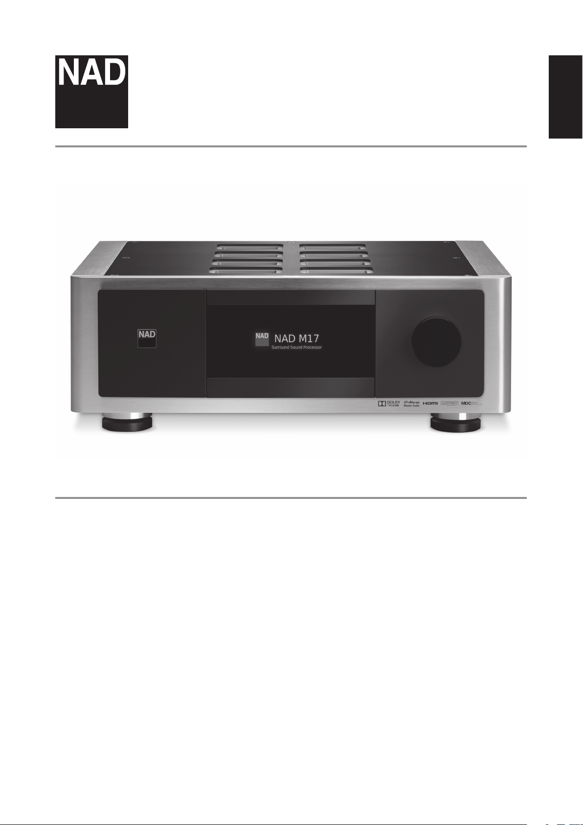
M17
AV Surround Sound Preamp Processor
ENGLISHFRANÇAISESPAÑOLITALIANODEUTSCHNEDERLANDSSVENSKAРУССКИЙ
Owner’s Manual
Page 2
IMPORTANT SAFETY INSTRUCTIONS
ENGLISH FRANÇAIS ESPAÑOL ITALIANO DEUTSCH NEDERLANDS SVENSKA РУССКИЙ
1. Read instructions - All the safety and operating instructions should be
read before the product is operated.
2. Retain instructions - The safety and operating instructions should be
retained for future reference.
3. Heed Warnings - All warnings on the product and in the operating
instructions should be adhered to.
4. Follow Instructions - All operating and use instructions should be
followed.
5. Cleaning - Unplug this product from the wall outlet before cleaning.
Do not use liquid cleaners or aerosol cleaners. Use a damp cloth for
cleaning.
6. Attachments - Do not use attachments not recommended by the
product manufacturer as they may cause hazards.
7. Water and Moisture - Do not use this product near water-for example,
near a bath tub, wash bowl, kitchen sink, or laundry tub; in a wet
basement; or near a swimming pool; and the like.
8. Accessories - Do not place this product on an unstable cart, stand,
tripod, bracket, or table. The product may fall, causing serious injury
to a child or adult and serious damage to the product. Use only with a
cart, stand, tripod, bracket, or table recommended by the manufacturer,
or sold with the product. Any mounting of the product should follow
the manufacturer’s instructions, and should use a mounting accessory
recommended by the manufacturer.
9. Cart - A product and cart combination should be moved
with care. Quick stops, excessive force, and uneven surfaces
may cause the product and cart combination to overturn.
10. Ventilation - Slots and openings in the cabinet are provided for
ventilation to ensure reliable operation of the product and to protect it
from overheating. These openings must not be blocked or covered. The
openings should never be blocked by placing the product on a bed,
sofa, rug, or other similar surface. This product should not be placed in a
built-in installation such as a bookcase or rack unless proper ventilation
is provided or the manufacturer’s instructions have been adhered to.
11. Power Sources - This product should be operated only from the type
of power source indicated on the marking label and connected to
a MAINS socket outlet with a protective earthing connection. If you
are not sure of the type of power supply to your home, consult your
product dealer or local power company.
12. Power-Cord Protection - Power-supply cords should be routed so that
they are not likely to be walked on or pinched by items placed upon or
against them, paying particular attention to cords at plugs, convenience
receptacles, and the point where they exit from the product.
13. Mains Plug - Where the mains plug or an appliance coupler is used
as the disconnect device, the disconnect device shall remain readily
operable.
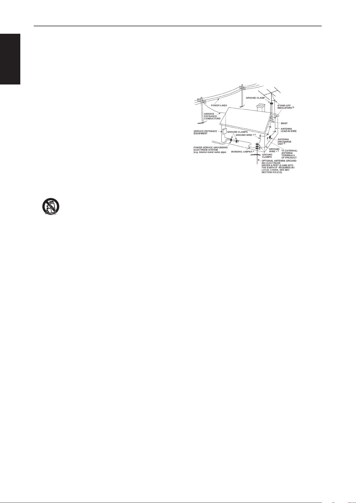
14. Outdoor Antenna Grounding - If an outside antenna or cable system
is connected to the product, be sure the antenna or cable system is
grounded so as to provide some protection against voltage surges
and built-up static charges. Article 810 of the National Electrical Code,
ANSI/NFPA 70, provides information with regard to proper grounding
of the mast and supporting structure, grounding of the lead-in wire
to an antenna discharge unit, size of grounding conductors, location
of antenna discharge unit, connection to grounding electrodes, and
requirements for the grounding electrode.
NOTE TO CATV SYSTEM INSTALLER
This reminder is provided to call the CATV system installer’s attention to Section 820-40 of
the NEC which provides guidelines for proper grounding and, in particular, specifies that
the cable ground shall be connected to the grounding system of the building, as close
to the point of cable entry as practical.
15. Lightning - For added protection for this product during a lightning
storm, or when it is left unattended and unused for long periods of
time, unplug it from the wall outlet and disconnect the antenna or
cable system. This will prevent damage to the product due to lightning
and power-line surges.
16. Power Lines - An outside antenna system should not be located in the
vicinity of overhead power lines or other electric light or power circuits,
or where it can fall into such power lines or circuits. When installing an
outside antenna system, extreme care should be taken to keep from
touching such power lines or circuits as contact with them might be
fatal.
17. Overloading - Do not overload wall outlets, extension cords, or
integral convenience receptacles as this can result in a risk of re or
electric shock.
18. Flame Sources - No naked ame sources, such as lighted candles,
should be placed on the product.
19. Object and Liquid Entry - Never push objects of any kind into this
product through openings as they may touch dangerous voltage points
or short-out parts that could result in a re or electric shock. Never spill
liquid of any kind on the product.
20. Headphones - Excessive sound pressure form earphones and
headphones can cause hearing loss.
21. Damage Requiring Service - Unplug this product from the wall outlet
and refer servicing to qualied service personnel under the following
conditions:
a. When the power-supply cord or plug is damaged.
b. If liquid has been spilled, or objects have fallen into the product.
c. If the product has been exposed to rain or water.
d. If the product does not operate normally by following the operating
instructions. Adjust only those controls that are covered by the
operating instructions as an improper adjustment of other controls
may result in damage and will often require extensive work by a
qualied technician to restore the product to its normal operation.
e. If the product has been dropped or damaged in any way.
f. When the product exhibits a distinct change in performance-this
indicates a need for service.
22. Replacement Parts - When replacement parts are required, be sure
the service technician has used replacement parts specied by the
manufacturer or have the same characteristics as the original part.
Unauthorized substitutions may result in re, electric shock, or other
hazards.
2
Page 3
IMPORTANT SAFETY INSTRUCTIONS
23. Battery Disposal - When disposing of used batteries, please comply
with governmental regulations or environmental public instruction’s
rules that apply in your country or area.
24. Safety Check - Upon completion of any service or repairs to this
product, ask the service technician to perform safety checks to
determine that the product is in proper operating condition.
25. Wall or Ceiling Mounting - The product should be mounted to a wall
or ceiling only as recommended by the manufacturer.
WARNING
The lightning ash with arrowhead symbol, within an
equilateral triangle, is intended to alert the user to the presence
of uninsulated “dangerous voltage” within the product’s
enclosure that may be of sucient magnitude to constitute a
risk of electric shock to persons
The exclamation point within an equilateral triangle is intended
to alert the user to the presence of important operating
and maintenance (servicing) instructions in the literature
accompanying the appliance.
CAUTION
Changes or modications to this equipment not expressly approved by
NAD Electronics for compliance could void the user’s authority to operate
this equipment.
CAUTION
To prevent electric shock, match wide blade of plug to wide slot, fully insert.
CAUTION
Marking and rating plate can be found at the rear panel of the apparatus.
WARNING
To reduce the risk of re or electric shock, do not expose this apparatus to
rain or moisture.
The apparatus shall not be exposed to dripping or splashing and that no
objects lled with liquids, such as vases, shall be placed on apparatus.
Mains plug is used as disconnect device and it should remain readily
operable during intended use. In order to disconnect the apparatus from
the mains completely, the mains plug should be disconnected from the
mains socket outlet completely.
Battery shall not be exposed to excessive heat such as sunshine, re or the like.
CAUTION
Danger of explosion if battery is incorrectly replaced. Replace only with the
same or equivalent type.
ENGLISHFRANÇAISESPAÑOLITALIANODEUTSCHNEDERLANDSSVENSKAРУССКИЙ
THE EQUIPMENT MUST BE CONNECTED TO AN EARTHED MAINS SOCKET-OUTLET.
CAUTION REGARDING PLACEMENT
To maintain proper ventilation, be sure to leave a space around the unit
(from the largest outer dimensions including projections) than is equal to,
or greater than shown below.
Left and Right Panels: 10 cm
Rear Panel: 10 cm
Top Panel: 10 cm
FCC STATEMENT
This equipment has been tested and found to comply with the limits for Class
B digital device, pursuant to Part 15 of the FCC Rules. These limits are designed
to provide reasonable protection against harmful interference in a residential
installation. This equipment generates, uses, and can radiate radio frequency
energy and, if not installed and used in accordance with the instructions, may
cause harmful interference to radio communications. However, there is no
guarantee that interference will not occur in a particular installation. If this
equipment does cause harmful interference to radio or television reception, which
can be determined by turning the equipment o and on, the user is encouraged
to try to correct the interference by one or more of the following measures:
• Reorient or relocate the receiving antenna.
• Increase the separation between the equipment and receiver.
• Connect the equipment into an outlet on a circuit dierent from that to
which the receiver is connected.
• Consult the dealer or an experienced radio TV technician for help.
An appliance with a protective earth terminal should be connected to a
mains outlet with a protective earth connection.
IF IN DOUBT CONSULT A COMPETENT ELECTRICIAN.
This product is manufactured to comply with the radio
interference requirements of EEC DIRECTIVE 2004/108/EC.
NOTES ON ENVIRONMENTAL PROTECTION
At the end of its useful life, this product must not be disposed
of with regular household waste but must be returned to a
collection point for the recycling of electrical and electronic
equipment. The symbol on the product, user’s manual and
packaging point this out.
The materials can be reused in accordance with their markings. Through
re-use, recycling of raw materials, or other forms of recycling of old
products, you are making an important contribution to the protection of
our environment.
Your local administrative oce can advise you of the responsible waste
disposal point.
RECORD YOUR MODEL NUMBER NOW, WHILE YOU CAN SEE IT
The model and serial number of your new M17 are located on the back of
the cabinet. For your future convenience, we suggest that you record these
numbers here:
Model number : . . . . . . . . . . . . . . . . . . . . . . . . . . . . . . . . . . . . . .
Serial number : ......................................
NAD is a trademark of NAD Electronics International, a division of Lenbrook Industries Limited
Copyright 2015, NAD Electronics International, a division of Lenbrook Industries Limited
3
Page 4

INTRODUCTION
TABLE OF CONTENTS
ENGLISH FRANÇAIS ESPAÑOL ITALIANO DEUTSCH NEDERLANDS SVENSKA РУССКИЙ
IMPORTANT SAFETY INSTRUCTIONS .........................2
INTRODUCTION
GETTING STARTED ...............................................5
WHAT’S IN THE BOX ..................................................5
CHOOSING A LOCATION .............................................5
DEFAULT SOURCE SETTINGS .........................................5
RESTORING M17 TO ITS FACTORY DEFAULT SET TINGS ................5
IDENTIFICATION OF CONTROLS
FRONT PANEL ....................................................6
REAR PANEL .....................................................8
OPERATION
USING THE M17 – MAIN MENU ...................................11
ABOUT THE ONSCREEN DISPLAY OSD ............................ 11
MAIN MENU ........................................................ 11
LISTENING MODE .................................................. 11
ADJUSTING LISTENING MODES .................................... 12
DSP OPTIONS ......................................................13
TONE CONTROLS ................................................... 14
ZONE CONTROLS. . . . . . . . . . . . . . . . . . . . . . . . . . . . . . . . . . . . . . . . . . . . . . . . . . . 14
USING THE M17 – SETUP MENU ..................................15
SETUP MENU ....................................................... 15
CONTROL SETUP ................................................... 15
SOURCE SETUP .................................................... 16
SOURCE SETUP NORMAL VIEW ...................................16
SOURCE SETUP TABLE VIEW ....................................... 17
SPEAKER SETUP .................................................... 18
AUDYSSEY AUTO CALIBRATION .................................... 18
SPEAKER CONFIGURATION ......................................... 20
SPEAKER LEVELS .................................................... 20
SPEAKER DISTANCE ................................................21
ADJUSTING THE VOLUME ..........................................21
ADJUSTING CHANNEL LEVELS “ON THE FLY’ ........................ 22
ZONE SETUP ....................................................... 22
TRIGGER SETUP ....................................................23
LISTENING MODE SETUP ........................................... 23
DOLBY SETUP ...................................................... 25
DTS SETUP .........................................................25
DTS SURROUND MODES ........................................... 25
ENHANCED STEREO ................................................ 26
DISPLAY SETUP ..................................................... 26
A/V PRESETS ........................................................ 26
USING THE HTRM 2 REMOTE CONTROL ..........................30
CONTROLLING THE M17 ............................................30
LEARNING CODES FROM OTHER REMOTES ......................... 31
PUNCH THROUGH .................................................. 31
COPY A COMMAND FROM ANOTHER KEY .......................... 31
MACRO COMMANDS ............................................... 31
KEY ILLUMINATION TIMEOUT ....................................... 32
CONFIGURING KEY ILLUMINATION ................................. 32
FACTORY RESET .................................................... 32
DELETE MODE ...................................................... 32
LOADING CODELIBRARIES ......................................... 33
SEARCH MODE ..................................................... 33
CHECKING CODELIBRARY NUMBER ................................ 33
SUMMARY OF THE HTRM 2 MODES ................................34
USING THE ZR 7 REMOTE CONTROL ................................ 34
REFERENCE
TROUBLESHOOTING ............................................35
SPECIFICATIONS ................................................36
THANK YOU FOR CHOOSING NAD.
The M17 AV Surround Sound Preamp Processor is a technologically advanced
and highly capable product — yet we have invested great eort in making it
simple and easy to use. The M17 delivers a range of genuinely useful options
for surround sound and stereo listening alike, using powerful digital signal
processing and superbly accurate digital-audio circuitry. However, we have also
been careful to ensure that the M17 is as musically transparent, faithful to every
video detail and spatially accurate as possible, incorporating much of what
we’ve learned from a quarter-century’s experience designing audio, video and
home-theater components. As with all our products, NAD’s “Music First” design
philosophy guided the M17’s design, such that it can condently promise you
both state-of-the-art surround home-theater and audiophile-quality music
listening for years to come.
NAD SHALL NOT BE HELD LIABLE FOR ANY TECHNICAL OR USER INTERFACE DISCREPANCIES IN THIS MANUAL. THE M17 OWNER’S
MANUAL MAY BE SUBJECT TO CHANGE WITHOUT PRIOR NOTICE. CHECK OUT THE NAD WEBSITE FOR THE LATEST VERSION OF THE M17
OWNER’S MANUAL.
We encourage you to take a few minutes now to read right through this
manual. Investing a little time here at the outset might save you a good
deal of time later, and is by far the best way to ensure that you make the
most of your investment in the M17, and get the most from this powerful
and exible home-theater component.
One more thing: We urge you to register your M17 ownership on the NAD
Worldwide Web site:
http://NADelectronics.com/salon
For warranty information contact your local distributor.
4
Page 5
INTRODUCTION
GETTING STARTED
WHAT’S IN THE BOX
Packed with your M17 you will nd
• A detachable mains power cord
• Audyssey microphone
• 3.5mm female jack to RCA plug Adapter for Audyssey microphone input
• HTRM 2 remote control with 4 AA batteries
• ZR 7 zone remote control with 3V CR2025 battery
• Four pieces of magnetic feet
• Cleaning cloth
• USB ash drive
• Quick Setup Guide
SAVE THE PACKAGING
Please save the box and all of the packaging in which your M17 arrived.
Should you move or otherwise need to transport your M17, this is by far the
safest container in which to do so. We’ve seen too many otherwise perfect
components damaged in transit for lack of a proper shipping carton, so
please: Save that box!
CHOOSING A LOCATION
Choose a location that is well ventilated (with at least several inches to
both sides and behind), and that will provide a clear line of sight, within
25 feet / 8meters, between the M17’s front panel and your primary
listening/viewing position—this will ensure reliable infrared remote control
communications. The M17 generates a modest amount of heat, but
nothing that should trouble adjacent components.
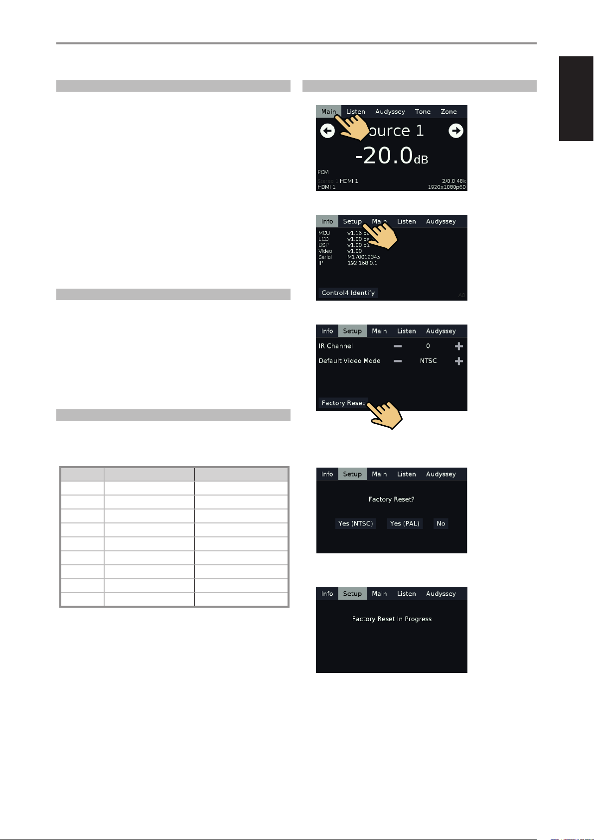
RESTORING M17 TO ITS FACTORY DEFAULT SETTINGS
1 Press and hold front panel’s “Main” display.
ENGLISHFRANÇAISESPAÑOLITALIANODEUTSCHNEDERLANDSSVENSKAРУССКИЙ
2 Select “Setup” display option.
3 Select “Factory Reset” display option.
It is perfectly possible to stack the M17 on top of other components, but
the reverse usually should be avoided.
DEFAULT SOURCE SETTINGS
The following table lists the default SOURCE settings. Note that the Audio
input settings show both digital and analog audio input. Digital input will
always take precedence over analog audio input even if both are present.
Source Audio Input Video Input
Source 1 HDMI 1/Audio 1 IN HDMI 1
Source 2 HDMI 2/Audio 2 IN HDMI 2
Source 3 HDMI 3/Audio 3 IN HDMI 3
Source 4 HDMI 4/Audio 4 IN HDMI 4
Source 5 Optical 1 IN/Audio 5 IN Video 1 IN
Source 6 Optical 2 IN/Audio 6 IN Video 2 IN
Source 7 Coaxial 1 IN/Audio 6 IN Video 3 IN
Source 8 Optical 3 IN Component Video Input 1
Source 9 Coaxial 2 IN Component Video Input 2
To modify the above default settings and for a better understanding of
source setting and combinations, please refer to the item about “SOURCE
SETUP” in the “USING THE M17 - SETUP MENU” segment of the “OPERATION”
section.
4 Select between “Yes (NTSC)” and “Yes (PAL) to select video mode after
Factory Reset. Select “No” if you decide not to reset your M17.
5 Factory reset is complete after the display below and the M17 going to
standby mode.
5
Page 6

ENGLISH FRANÇAIS ESPAÑOL ITALIANO DEUTSCH NEDERLANDS SVENSKA РУССКИЙ
IDENTIFICATION OF CONTROLS
FRONT PANEL
1
av surround sound preamp processor
1 o (STANDBY)
• Press o (Standby) button for the M17 to be switched ON from
standby mode. The Power indicator will turn from amber to bright/
white color.
• Pressing o (Standby) button again switches back M17 to standby
mode. The Power indicator will illuminate to amber color at standby
mode.
• The o (Standby) button cannot activate the M17 with the rear
panel POWER switched o.
IMPORTANT NOTES
• Refer also to +12V TRIGGER IN (OFF/AUTO) of IDENTIFICATION OF
CONTROLS - REAR PANEL.
• For the o (Standby) button to activate, two conditions must be
completed.
a Plug-in the supplied mains power cord to a mains power source.
Connect corresponding end of the mains power cord to the AC mains
input of M17 and the plug connected to a mains power source.
b The rear panel POWER switch must be set to ON position.
M17
© NAD M17
4 52 3
4 DISPLAY
• Show visual and menu information according to the display settings
selected.
• There are four display options – Main, Listen, Audyssey, Tone and
Zone.
• Use your nger to press and select any of these display options to
show their corresponding menu options or settings.
The following are sample screenshots of the four display options with
corresponding description of the information shown.
MAIN
2 POWER INDICATOR
• This indicator will light up amber when the M17 is at standby mode.
• When the M17 is powered up from standby mode, this indicator will
turn from amber to bright/white color.
3 REMOTE SENSOR
• Point the HTRM 2 remote control at the remote sensor and press the
buttons.
• Do not expose the remote sensor of the M17 to a strong light
source such as direct sunlight or illumination. If you do so, you may
not be able to operate the M17 with the remote control.
Distance: About 23ft (7m) from the front of the remote sensor.
Angle: About 30o in each direction of the front of the remote sensor.
6
Source 1: Current Source.
-20.0 dB: Volume level.
: Go to previous or next Source.
DTS-HD Master Audio: Audio Codec - Detected audio stream format.
HDMI 1/HDMI 1: Audio and video input source.
3/2.1 192k: Audio Source format; sample rate.
1920x1080p60: Video mode - Video resolution of current source with
frame rate.
Page 7
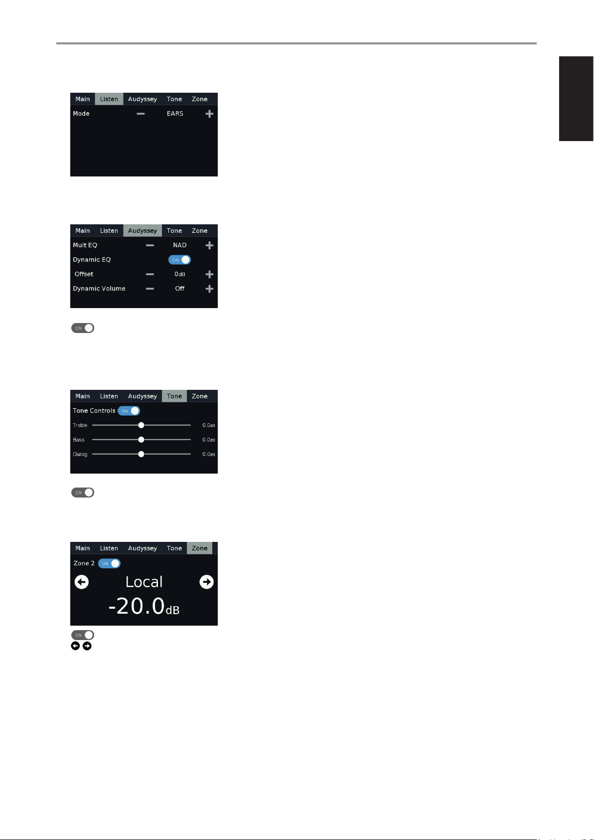
LISTEN
EARS: Listening mode.
- +: Go to previous or next Listening mode.
AUDYSSEY
-/+: Go to previous or next option.
: Slide to turn ON or OFF Dynamic EQ.
IDENTIFICATION OF CONTROLS
FRONT PANEL
ENGLISHFRANÇAISESPAÑOLITALIANODEUTSCHNEDERLANDSSVENSKAРУССКИЙ
For descriptions of the above item, refer to sections about DSP OPTIONS
and AUDYSSEY CALIBRATION.
TONE
: Slide to turn ON or OFF Tone Controls. At OFF setting, tone
controls are disabled or defeated.
h : Slide to adjust treble, bass or dialog level.
ZONE
: Slide to turn ON or OFF Zone 2.
: Go to previous or next Source.
5 VOLUME
• Use this control to adjust the overall loudness of the signal output at
AUDIO PRE-OUT.
• The default volume level is -20dB.
7
Page 8
ENGLISH FRANÇAIS ESPAÑOL ITALIANO DEUTSCH NEDERLANDS SVENSKA РУССКИЙ
IDENTIFICATION OF CONTROLS
REAR PANEL
1 2 3 4 5
© NAD M17
R L R L R L
FRONT SURR SURR-B CENTER SUBW
IN ININ IN
OUT
L
R
AUDIO 1
1 2 3
IN
ZONE 3
AUDIO 2 AUDIO 3 AUDIO 4 AUDIO 5 AUDIO 6 AUDIO 7 ZONE 2
VIDEO INPUT
VIDEO OUT
OUT
IN
ZONE 4
COMPONENT VIDEO INPUT 1
Y
CB/PB CR/PR
COMPONENT VIDEO INPUT 2
IN
MONITOR OUT
ZONE 2
Y CB/PB CR/PR
MONITOR OUT
OUT
8
IN ININ IN
OUT
L
6
R
AUDIO 1
IN
ZONE 3
AUDIO 2 AUDIO 3 AUDIO 4 AUDIO 5 AUDIO 6 AUDIO 7
7
1 2 3
VIDEO INPUT
VIDEO OUT
OUT
IN
ZONE 4
COMPONENT VIDEO INPUT 1
Y
CB/PB CR/PR
COMPONENT VIDEO INPUT 2
IN
MONITOR OUT
ZONE 2
Y CB/PB CR/PR
MONIT
OR OUT
OUT
ZONE 2
AUDIO PRE-OUT BALANCED
1
3
COAXIAL IN
MONITOR OUT 1 MONITOR OUT 2
10 11
9
AUDIO PRE-OUT
L
R
SURR SURR-B
FRONT
DIGITAL AUDIO IN DIGITAL AUDIO OUT
2
1 2 3 4
4
OPTICAL IN
LAN
HDMI 4
HDMI, the HDMI logo and High-Definition Multimedia Interface are trademarks
or registered trademarks of HDMI Licensing LLC.
HDMI 1
CENTER
L
R
SUBW1
1
2
COAXIAL OUT OPTICAL OUT
HDMI 6
HDMI 5
HDMI 3
HDMI 2
SUBW2
1 2
12 13 14 15
+12V TRIGGER IN
OFF AUTO
RS232
UNSWITCHED AC OUTLET
120V~60Hz 120W 1A MAX
IN
IR
OUT 2
OUT 1
OUT 4 OUT 3
OUT 1
POWER
120V~60Hz
+12V TRIGGER
IN
ON
OUT 2
OUT 3
ATTENTION!
Please make sure that the M17 is powered o or unplugged from the mains power source before making any connections. It is also advisable to power
down or unplug all associated components while making or breaking any signal or AC power connections.
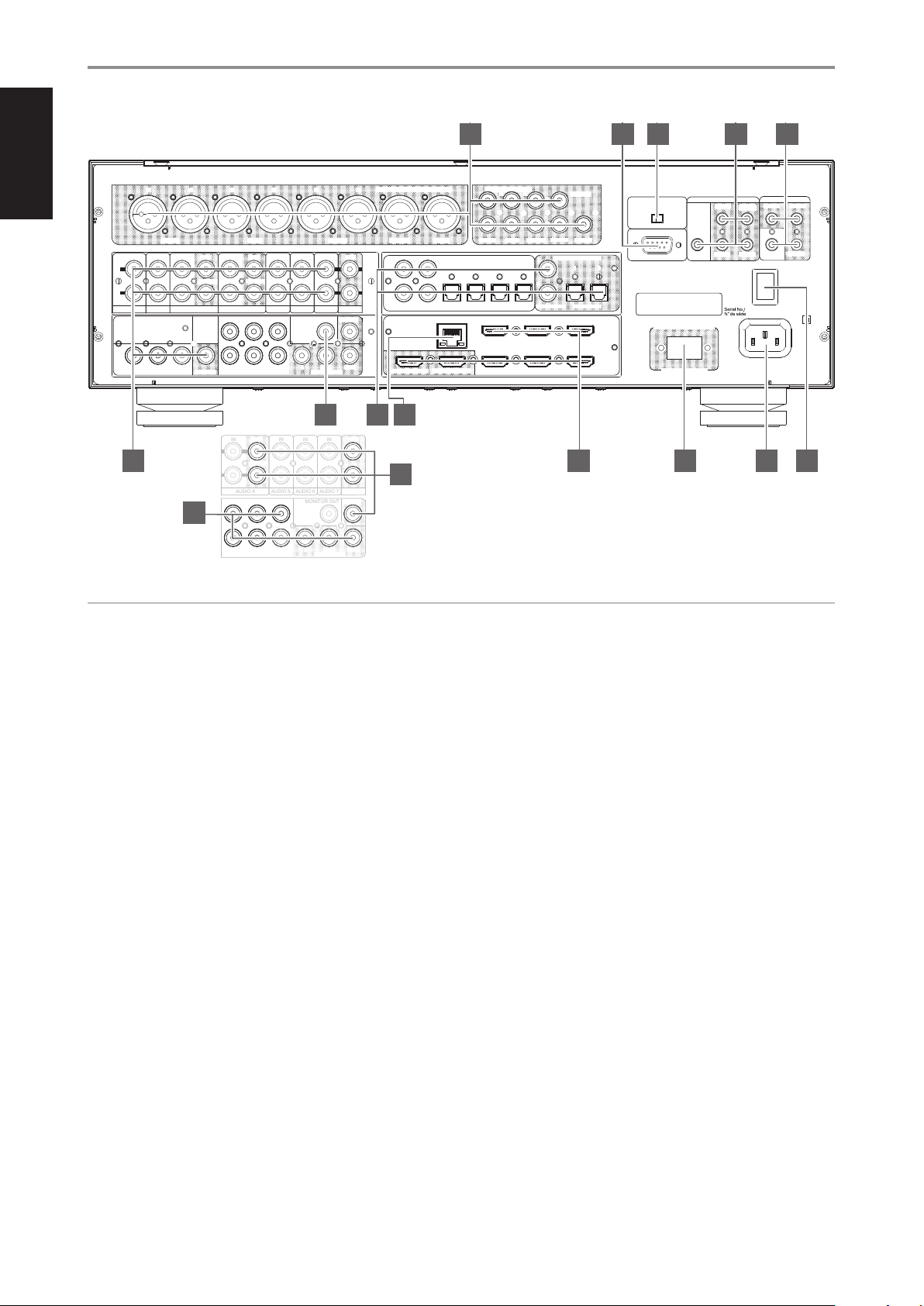
1 AUDIO PRE-OUT (BALANCED)
• The AUDIO PRE-OUT makes it possible to use the M17 as a pre-
amplier to external power ampliers for some or all channels.
• Depending upon the source’s conguration, analog audio
output connection can be made up to seven channels either via
BALANCED or SINGLE-ENDED output ports.
• Use the AUDIO PRE OUT (BALANCED) if the external source to be
connected has BALANCED audio input. Superior audio quality
is ensured with the distinctive noise reduction capability of
BALANCED connection with XLR jacks.
• Connect FRONT L, FRONT R, CENTER, SURR R, SURR L, SURR-BL and
SURR-BR to the respective channel input of a power amplier or
ampliers driving the corresponding applicable speakers.
• Connect the SUBW output to powered (“active”) subwoofers or to
power amplier channels driving a passive system.
AUDIO PRE OUT (SINGLE-ENDED)
• Use single-ended AUDIO PRE OUT for sources that are not equipped
with BALANCED analog audio input.
2 RS 232
NAD is a certied partner of AMX and Crestron and fully supports
these external devices. Check out the NAD website for information
about AMX and Crestron compatibility with NAD. See your NAD audio
specialist for more information.
• Connect this interface using RS-232 serial cable (not supplied) to
any Windows compatible PC to allow remote control of the M17 via
compatible external controllers.
• Refer to the NAD website for information about RS232 Protocol
documents and PC interface program.
3 +12V TRIGGER IN (OFF/AUTO)
• The settings of +12V TRIGGER IN (OFF/AUTO) together with +12V
TRIGGER (IN) (item 5) aect the manner on how the M17 can be
switched ON from standby mode or back to standby mode.
+12V TRIGGER IN (AUTO)
• If +12V TRIGGER IN (OFF/AUTO) is set to AUTO, pressing the front
panel o (Standby) button or HTRM 2’s ON/OFF button cannot
switch ON the M17 from standby mode and vice-versa. Both
control buttons are eectively disabled thereby handling the
function of powering up the M17 to an external controller.
• If +12V TRIGGER IN (OFF/AUTO) is set to AUTO, powering up the
M17 is dependent upon the “Auto Trigger In” setting at the “Trigger
Setup” menu as well as the absence or presence of +12V at +12V
TRIGGER (IN)(item 5).
+12V TRIGGER IN (OFF)
• Slide the +12V TRIGGER IN (OFF/AUTO) switch to OFF for the M17 to
be normally switched ON from standby mode and vice-versa using
the front panel o (Standby) button or HTRM 2’s ON/OFF button.
• The +12V TRIGGER (IN) (item 5) is disabled with +12V TRIGGER IN
(OFF/AUTO) set to OFF.
8
Page 9
IDENTIFICATION OF CONTROLS
REAR PANEL
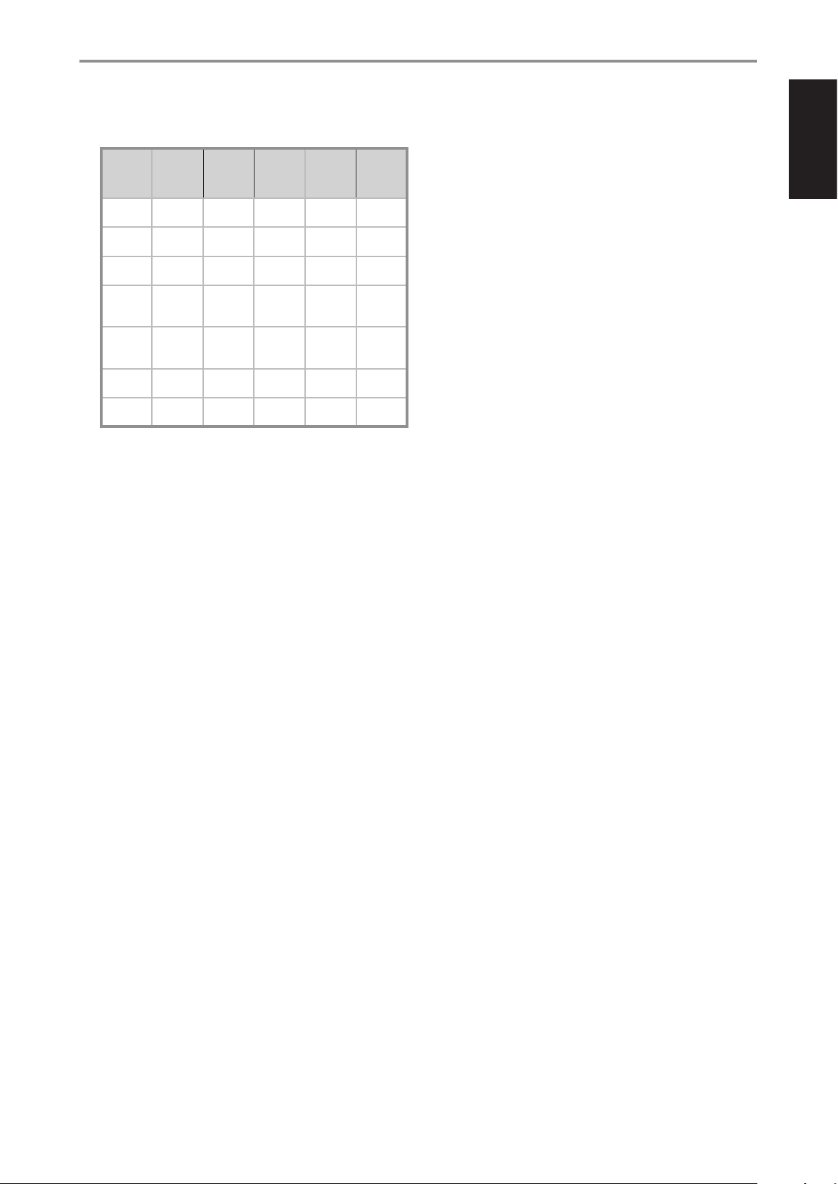
Below is a table of sample combination settings with respect to
switching ON the M17 from standby mode and vice versa.
+12V
TRIGGER IN
(OFF/AUTO)
AUTO +12V Main, All ON ON Operating
AUTO +12V Main, All OFF OFF Operating
AUTO 0V Main, All ON/OFF ON/OFF Standby
AUTO 0V Zone 2,
AUTO 0V Zone 2,
OFF +12V
OFF +12V
4 IR IN/IR OUT 1-4
These mini-jacks accept and output remote-controlled codes in
electrical format, using industry-standard protocols, for use with “IRrepeater” and multi-room systems and related technologies.
• All NAD products with IR IN/IR OUT features are fully compatible
IR IN
• This input is connected to the output of an IR (infrared) repeater
+12V
TRIGGER(IN)
(item 5)
or 0V
or 0V
with the M17. For non-NAD models, please check with your other
product’s service specialists with respect to their compatibility to
the M17’s IR features.
(Xantech or similar) or the IR output of another compatible device
to allow control of the M17 from a remote location.
AUTO
TRIGGER IN
Zone 3 or
Zone 4
Zone 3 or
Zone 4
Any
setting
Any
setting
FRONT
PANEL
o (STANDBY)
ON ON Operating
OFF OFF Standby
ON ON Operating
OFF OFF Standby
HTRM 2 (ON/
OFF)
M17 POWER
MODE STATE
mode
mode
mode
mode
mode
mode
mode
5 +12V TRIGGER OUT1/OUT2/OUT3
The M17 has three +12V TRIGGER OUT ports (OUT 1, OUT2 and OUT3)
that can be congured to supply +12V DC to a linked component or
system. See discussion on “Trigger Setup” at the “Setup Menu” literature
for guidelines on how to congure +12V TRIGGER IN/OUT.
• Use a 3.5mm mini-jack connector to pass +12 volts at a maximum
current of 50 milliamps to an auxiliary equipment such as a
multichannel amplier or subwoofer. The center conductor (hot) of
the 3.5mm jack is the control signal. The outside conductor (shield)
is the ground return-path.
• This output will be 12V when the M17 is ON and 0V when the unit is
either OFF or in standby mode.
+12V TRIGGER IN
With this input triggered by a 12V DC supply, the M17 can be switched
ON remotely from standby mode by compatible devices such as
ampliers, preampliers, receivers, etc. If the 12V DC supply is cut o,
the M17 will return to standby mode.
• Connect this +12V TRIGGER INPUT to the remote device’s
corresponding +12V DC output jack using a mono cable with
3.5mm male plug. The controlling device must be equipped with a
+12V trigger output to use this feature.
6 AUDIO 1-7 IN/VIDEO INPUT 1-3
• These comprise the M17’s other sets of principal input. Connect
these audio and video input ports to corresponding output ports of
compatible source components such as DVD players, CD players or
cable/satellite boxes.
• AUDIO 5 IN, AUDIO 6 IN and AUDIO 7 IN are ideal for the connection
of the analog output of line-level audio sources like a CD player or
Stereo tuner.
• The Left Channel of AUDIO 1 IN is the assigned port where the
supplied 3.5mm female jack to RCA plug Adapter can be connected.
Plug in the Audyssey microphone into the adapter for Audyssey
Auto Calibration.
ENGLISHFRANÇAISESPAÑOLITALIANODEUTSCHNEDERLANDSSVENSKAРУССКИЙ
IR OUT 1- 4
• Connect IR OUT 1 (or IR OUT 2/IR OUT 3/IR OUT 4) to the IR IN jack of
a compatible device.
• Command and control the linked compatible device by directing its
own remote control to M17’s infrared receiver.
IR IN and IR OUT 1/IR OUT 2/IR OUT 3/IR OUT 4
• Connect the M17’s IR IN to the IR OUT of a compatible device.
Connect also the M17’s IR OUT 1 (or IR OUT 2/IR OUT 3/IR OUT 4) to
the IR IN of a compatible device.
• With this setup, the M17 acts as an “IR-repeater” allowing the device
connected to the M17’ s IR IN control or command of the other
device linked to M17’s IR OUT 1 (or IR OUT 2/IR OUT 3/IR OUT 4).
AUDIO 3-4 OUT/VIDEO OUT
• Connect AUDIO 3 OUT (and/or AUDIO 4 OUT) to corresponding
recording components or audio/video input ports of compatible
sources like cassette deck, CD/DVD recorder or outboard audio
processors.
• The signal present at AUDIO 3 OUT is determined by the current
source selected. There will be no output at AUDIO 3 OUT when
AUDIO 3 is selected. Likewise, there will be no output at AUDIO
4 OUT when AUDIO 4 is the active source input. This prevents
feedback through the recording component thereby preventing
possible damage to your speakers.
• When congured, AUDIO 3 OUT and AUDIO 4 OUT are the same
assigned ports for Zone 3 and Zone 4 respectively. See also Zone
output description below.
7 COMPONENT VIDEO INPUT 1-2,
COMPONENT VIDEO MONITOR OUT
• Connect the Component Video Input to Component Video output
of compatible source components, typically a DVD player, BD
player, digital cable box or other applicable components. Connect
Component Video Monitor Out to the Component Video input of a
compatible video monitor/TV.
• Be sure to observe consistency in connecting the Y/Pb/Pr jacks
to the corresponding sources/inputs. The routing of the two
component video input is fully congurable via the Source Setup
item of the Setup Menu OSD.
• The M17’s sets of component video input and output are fully
wideband and compatible with allowable HDTV formats.
9
Page 10
ENGLISH FRANÇAIS ESPAÑOL ITALIANO DEUTSCH NEDERLANDS SVENSKA РУССКИЙ
IDENTIFICATION OF CONTROLS
REAR PANEL
8 MONITOR OUT (COMPOSITE VIDEO)
• Connect to the video input of a monitor/television using quality
dual-RCA connectors designed for video signals.
9 ZONE 2-3-4
• The M17 has three congurable Zones – Zone 2, Zone 3 and Zone
4. The Zone feature allows one to simultaneously experience in
a dierent zone or location of the house a Source assigned to a
particular zone.
• Send zone selected audio and video output to the corresponding
audio and video input of another zone. Use high quality patch
cables to reduce noise pickup over long distance runs.
• For a better understanding of zone settings, study below the section
about “Zone Controls” of the “Main Menu” discussion as well as the
item about “Zone Setup” under the “Setup Menu” literatures.
NOTES
• “Zone 4” is audio only and not associated with any video input sources.
• Zone 2 and Zone 3 video output are available only if the corresponding
zone’s video source is composite video.
10 DIGITAL AUDIO IN (COAXIAL IN 1-4, OPTICAL IN 1-4)
• Connect to the corresponding optical or coaxial digital output of
sources such as CD or BD/DVD players, digital cable box, digital
tuners and other applicable components.
• Coaxial and Optical digital input association is congurable via the
Source Setup item of the Setup Menu OSD.
DIGITAL AUDIO OUT (COAXIAL OUT 1-2, OPTICAL OUT 1-2)
• Connect the optical or coaxial DIGITAL AUDIO OUT to the
corresponding digital audio input of compatible devices such as
receivers, computer soundcard or other digital processors.
11 ETHERNET/LOCAL AREA NETWORK (LAN) PORT
LAN connection must be setup for wired connection to be established.
Set up a Wired Ethernet broadband router with broadband internet
connection. Your router or home network should have a built-in DHCP
server to consummate the connection.
• With Ethernet connection established, you can now control the
M17 using the NAD AVR Remote App that can be downloaded
from the Apple App store to your iOS device (iPhone, iPad or iPod
Touch). Ensure that your iOS device with the NAD AVR Remote App
is connected to the same network as the M17.
• The NAD AVR Remote App automatically discovers your network-
connected M17 and walks you through controlling and adjusting
fundamental functions including power, volume, source selection
and other basic setup features.
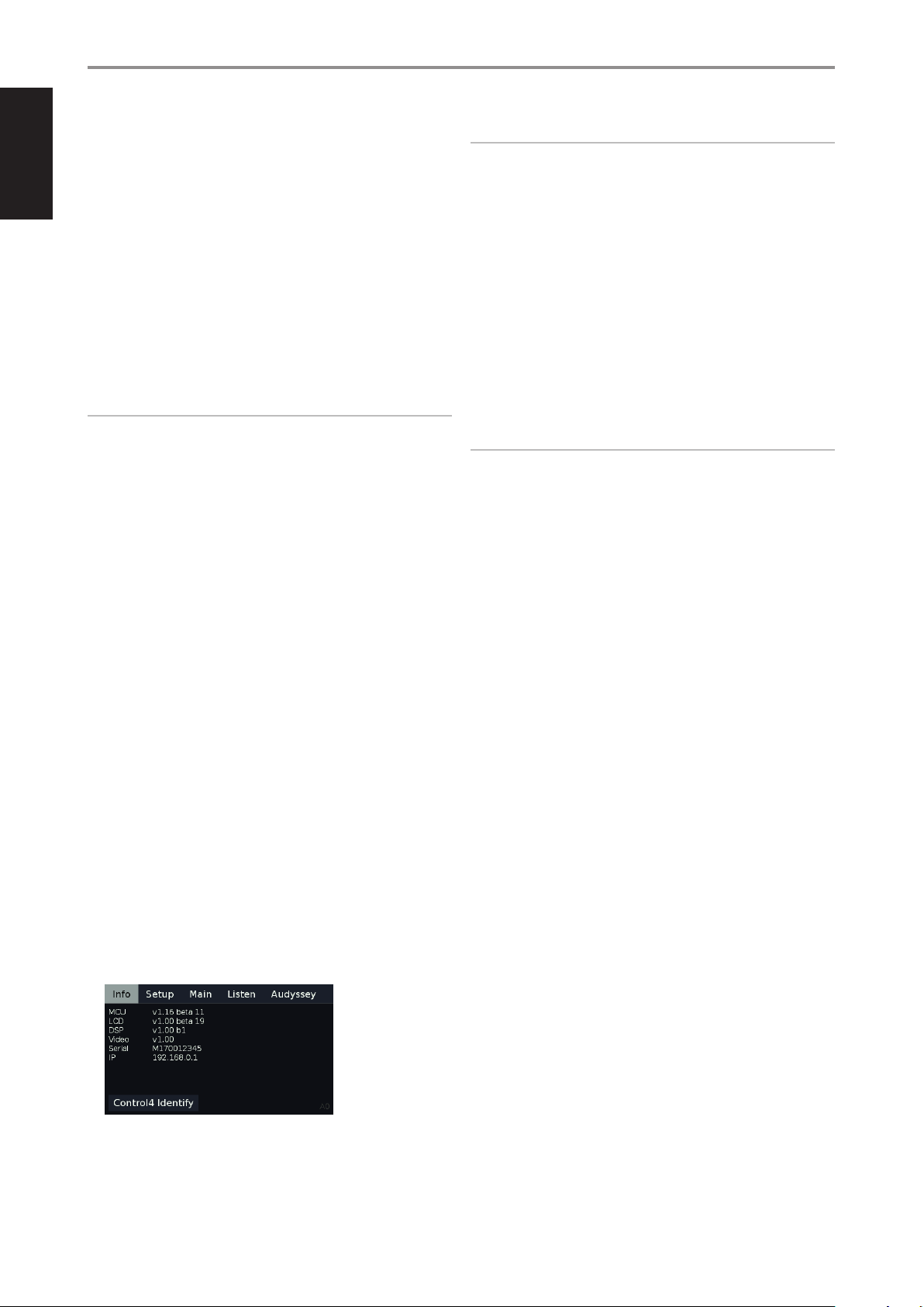
• The IP address of your network-connected M17 can be obtained.
Press and hold “Main” item in the front panel display menu until
below information is displayed.
NOTES
• NAD is not responsible for any malfunction of the M17 and/or the
internet connection due to communication errors or malfunctions
associated with your broadband internet connection or other connected
equipment. Contact your Internet Service Provider (ISP) for assistance or
the service bureau of your other equipment.
• Contact your ISP for policies, charges, content restrictions, service
limitations, bandwidth, repair and other related issues pertinent to
internet connectivity pertinent to internet connectivity.
12 HDMI (HDMI IN 1-6, HDMI MONITOR OUT 1-2)
• Connect the sets of HDMI input to the HDMI OUT connectors of
source components such as DVD player, BD player or HDTV satellite/
cable box.
• Connect the HDMI MONITOR OUT 1 and/or HMDI MONITOR OUT
2 to compatible HDTV or projector with HDMI input. Both HDMI
output ports display simultaneously the same audio/video source.
WARNING
Before connecting and disconnecting any HDMI cables, both the M17
and the ancillary source must be powered OFF and unplugged from the
AC outlet. Failure to observe this practice may cause permanent damage
to all equipment connected via HDMI sockets.
13 UNSWITCHED AC OUTLET (120V version model only)
• With M17 switched ON or at standby mode, mains power is always
available at this outlet.
• This outlet can be used for components that may require
continuous supply of AC mains; some tuners require uninterrupted
mains supply to retain preset memory, for instance.
• The total draw of all devices connected to this outlet must not
exceed 120 watts.
• Mains power at this outlet can be shut down by switching OFF the
M17 via the rear panel POWER switch.
14 AC MAINS INPUT
• The M17 comes supplied with a separate detachable mains power
cord. Before connecting the plug to the mains power source,
connect rmly rst the other end to M17’s AC Mains input socket.
• Always disconnect the mains power plug from the mains power
source rst, before disconnecting the cable from the M17’s AC
Mains input socket.
• Connect only to the prescribed AC outlet, i.e., 120V 60 Hz (for 120V
version models only) or 230V 50 Hz (for 230V version models only).
15 POWER
• Supply the AC mains power to the M17.
• When the POWER switch is set to ON position, the M17 goes to
standby mode as shown by the amber status condition of the front
panel Power indicator. Press the front panel o (Standby) button or
HTRM 2 remote control’s [ON] button to switch ON the M17 from
standby mode.
• If you intend not to use the M17 for long periods of time (such
as when on vacation), switch o the POWER switch. With POWER
switched o, neither the front panel o (Standby) button nor
HTRM2 remote control’s [ON] button can activate the M17.
10
Page 11
OPERATION
USING THE M17 MAIN MENU
ABOUT THE ON-SCREEN DISPLAY (OSD)
The M17 employs a simple, self-explanatory system of on-screen display
“menus” that will appear on the connected video monitor/TV. These are
required during the setup process (and are useful in day-to-day operation),
so be sure to connect the monitor/TV before proceeding with setup.
DISPLAY THE OSD
Press [E] or [ENTER] buttons of the HTRM 2 remote control to display the
M17’s Main Menu on your video monitor/TV. If the OSD does not appear,
check your MONITOR OUT connections.
NAVIGATING THE OSD AND MAKING CHANGES
To navigate through the OSD menu options, please do the following using
the HTRM 2 buttons:
1 Press [E] to select a menu item. Use [R/T] or in some cases, [ENTER],
to move up or down the Menu selections. Repeatedly press [E] to
advance or go further into the sub-menu of desired menu item.
2 Use [R/T] to set or change the parameter value (setting) of a menu
item.
3 Press [W] to save the settings or changes done on the current menu or
sub-menu. Pressing [W] will also return the user to the previous menu
or exit from a particular menu.
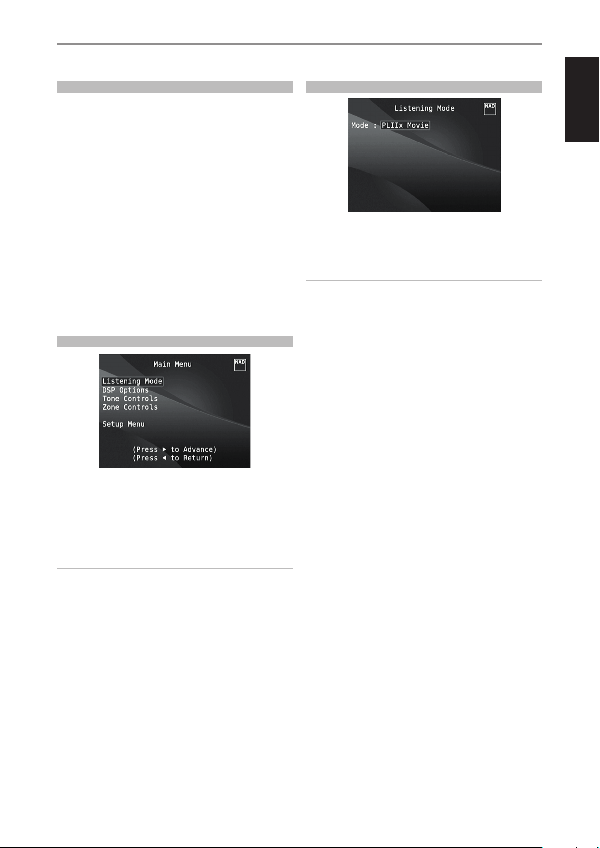
MAIN MENU
LISTENING MODE
ENGLISHFRANÇAISESPAÑOLITALIANODEUTSCHNEDERLANDSSVENSKAРУССКИЙ
The M17 oers distinct listening modes, tailored for dierent types of
recording or program material. With a two-channel (Stereo) source, the
following listening modes can be selected.
IMPORTANT NOTICE
The M17 is an AV Surround Sound Preamplier and therefore has no
speakers. The mention of “Speaker(s)” in this manual refers to the
speakers of your external amplier as interfaced with the M17.
STEREO
All output is directed to the front left/right channels. Low frequencies are
directed to the subwoofer if one is present in the Speaker settings. Select
“Stereo” when you wish to listen to a stereo (or monaural) production, such
as music CD or FM broadcast, without surround enhancement. Stereo
recordings whether in PCM/digital or analog form and whether surroundencoded or not encoded, are reproduced as recorded. Multi-channel digital
recordings (Dolby Digital and DTS) are reproduced in “Stereo Downmix”
mode via the front left/right channels only as Lt/Rt (left/right-total) signals.
The Main Menu contains the menu options for “Listening Mode”, “DSP
Options”, “Tone Controls”, “Zone Controls” and access to “Setup Menu”.
Follow the guidelines about “DISPLAY THE OSD” and “NAVIGATING THE OSD
AND MAKING CHANGES” to navigate through the menu options and their
sub-menu selections.
NOTE
The individual congurations set forth at “Listening Mode”, “DSP
Options” and “Tone Controls” are carried over whenever they are
enabled at A/V Presets setting. Please see the section “AV PRESETS” for
reference.
DIRECT
Analog or digital sources are automatically played in their native formats.
All the source’s audio channels are reproduced directly. This mode recreates
the original sound most faithfully thereby producing outstandingly high
quality audio.
DIRECT listening mode is selectable only during source playback. In order
to setup DIRECT as preferred listening mode, the following steps have to be
undertaken.
1 Go to LISTENING MODE SETUP under SETUP MENU. Select LISTENING
MODES. Under LISTENING MODES menu, set to “None” all the
parameter settings for Dolby, DTS, PCM and Analog.
2 Then, go to A/V PRESETS items under SETUP MENU. Scroll to LISTENING
MODE item and set to “Yes”. Store this LISTENING MODE setting to Preset
1 along with the other parameter settings by clicking “Save Current
Setup to Preset”.
3 This saved “Preset 1” setting can now be associated to any Source. Below
is a sample association.
a Under SOURCE SETUP (Normal View), go to SOURCE 1 and scroll
down to A/V Preset and set “A/V Preset” to “Preset 1”.
b Now, whenever SOURCE 1 is recalled with “Preset 1” associated to it,
the LISTENING MODE setting will always be DIRECT.
PRO LOGIC
Two-channel recordings, whether stereo or surround-encoded, are
reproduced with Dolby Pro Logic surround processing, yielding output to
front left/right, center and discrete left/right surround channels (assuming
these are present in the current “Speaker Conguration”). The surround
channel is monophonic, but it is reproduced in both surround speakers.
11
Page 12
ENGLISH FRANÇAIS ESPAÑOL ITALIANO DEUTSCH NEDERLANDS SVENSKA РУССКИЙ
OPERATION
USING THE M17 MAIN MENU
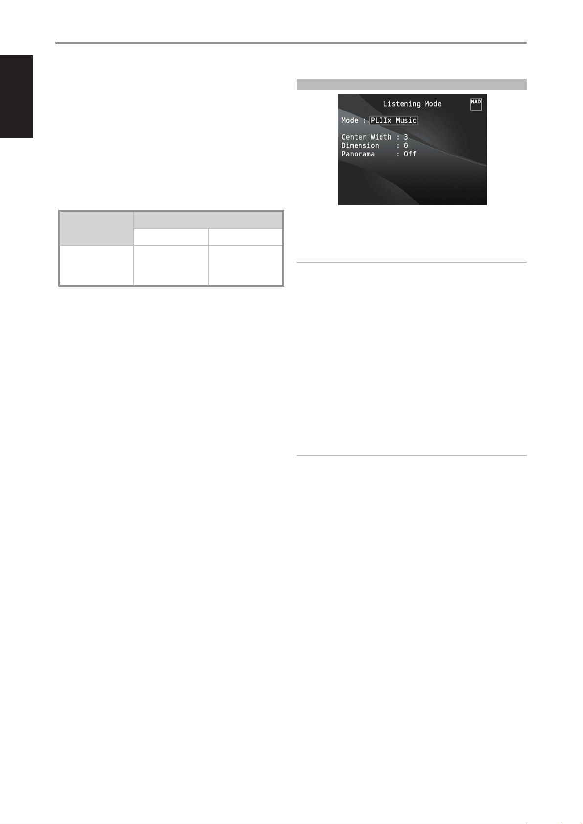
DOLBY PRO LOGIC IIx
Dolby Pro Logic IIx processes both stereo and 5.1 signals into a 6.1 or 7.1
channel output. At Dolby Pro Logic IIx, you can choose PLIIx Movie or PLIIx
Music modes to tailor your listening experience to the source material.
Dolby Pro Logic IIx surround processing yields more stable imaging and full
bandwidth sound to the rear channels in Movie mode oering sound that is
more similar to Dolby Digital decoding. For two channel signals, PLIIx Music
mode also features three additional user controls - Dimension, Center Width,
and Panorama. See also section about “Adjusting Listening Modes” below.
The following chart shows the channels available assuming they are
enabled in the “Speaker Conguration” menu:
Listening Mode
Two-Channel Sources
PLIIx Music
PLIIx Movie
DTS NEO: 6
Two-channel recordings, whether stereo or surround-encoded, are
reproduced with Neo: 6 surround with output to front left/right, center and
discrete left/right surround channels plus subwoofer (assuming these are
present in the current “Speaker Conguration”). The M17 provides two DTS
Neo: 6 variations - NEO:6 Cinema and NEO:6 Music. See also section about
“Adjusting Listening Modes” below.
EARS
Two-channel recordings, whether stereo or surround-encoded, are
reproduced with proprietary NAD surround processing with signals output
to the front left/right, center and discrete left/right surround channels,
plus subwoofer (assuming these are present in the current “Speaker
Conguration”). EARS does not employ the surround back speakers (if any).
EARS extracts the natural ambience present in nearly all well-produced
stereo recordings. It does not synthesize any ambience or other sonic
elements and thus remains truer to the sound of the original musical
performance than most other music-surround options.
Select EARS for listening to stereo music recordings and broadcasts.
EARS produces a subtle but highly natural and believable ambience from
nearly all “natural-acoustic” stereo recordings. Typically, these include
classical, jazz, and folk genres as well as numerous examples from others.
Its virtues include realistic, stable “front-stage” sonic imaging and spacious
but unexaggerated ambient “virtual acoustics” that remain faithful to the
original recording.
Active Decoded Output Channels
6.1 Speaker System 7.1 Speaker System
Front (left, right),
Center, Surround (left,
right), Back Surround,
Subwoofer
Front (left, right), Center,
Surround (left, right)
and Back Surround (left,
right), Subwoofer
ADJUSTING LISTENING MODES
Several of the M17’s listening modes have one or more selectable variations
and adjustable parameters that you can modify to suit your system or
personal preferences.
NOTE
Listening Mode parameter changes are maintained when you change
listening modes. You may also save a modied Listening Mode for easy
recall by saving it to a Preset (See “A/V Presets” below under Setup Menu
discussions).
PRO LOGIC IIx
PLIIx MOVIE is optimized for lm soundtracks.
PLIIx MUSIC for music recordings
Center Width (0 to 7): Modies the “hard-centeredness” of the center
image, by gradually mixing mono center content to the Front left/right
speakers as well. A setting of 0 retains the center-channel-only default
while a setting of 7 yields a fully phantom center channel.
Dimension (-7 to +7): Adjusts front-rear emphasis of the surround
eect independently from the relative channel levels.
Panorama (On/O): Adds a “wraparound” eect by extending some
stereo content into the surround channels.
NOTE
Pro Logic IIx mode will decode as PLII mode when the BACK surround
speakers are set to “OFF” from “Speaker Conguration” menu. See also
section about “Speaker Conguration” under “Speaker Setup” of the
Setup Menu.
DTS NEO: 6
NEO: 6 Cinema is optimized for lm soundtracks.
NEO: 6 Music for music recordings
Center Gain (0 to 0.5): Adjust for better center image in relation to the
surround sound channels.
ENHANCED STEREO
All recordings are reproduced in stereo via the maximum speaker
complement congured in the current “Speaker Conguration”. Enhanced
stereo can be useful for maximum volume from all channels or for multispeaker background music (cocktail party) listening. For this mode, Front,
Center, Surround and Back speakers can be turned ON/OFF as desired.
12
Page 13
OPERATION
USING THE M17 MAIN MENU
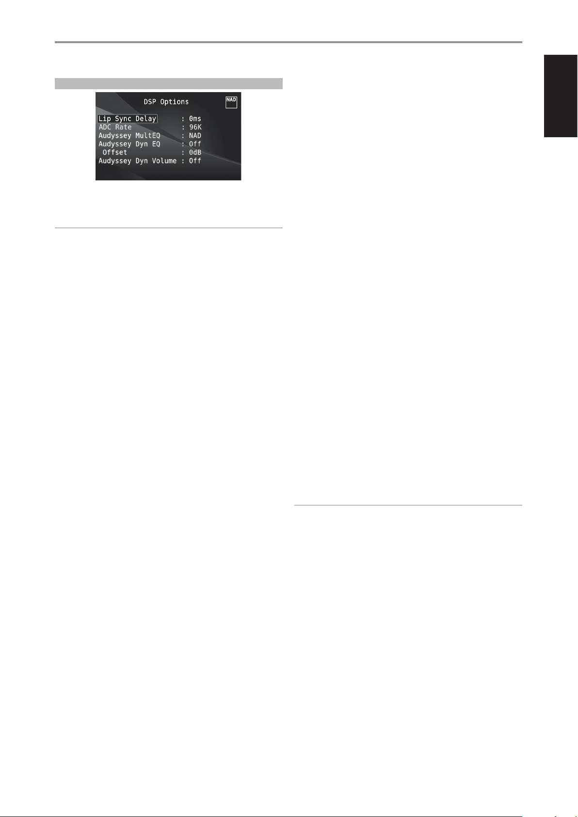
DSP OPTIONS
The following signal processing parameters can be setup under the DSP
(Digital Signal Processing) Options menu.
IMPORTANT NOTICE
The M17 is an AV Surround Sound Preamplier and therefore has no
speakers. The mention of “Speaker(s)” in this manual refers to the
speakers of your external amplier as interfaced with the M17.
LIP SYNC DELAY
DSP Options has the feature “Lip Sync Delay” whose function is to match
any delay that may occur in the picture relative to the audio.
By varying “Lip Sync Delay” from 0ms to 120ms, one can delay the audio
output in order to synchronize it with the video image.
ADC ANALOGTODIGITAL CONVERTER RATE
An analog audio input is converted to digital signal by making use of M17’s
superb circuitry called analog-to-digital converter (ADC).
Using this ADC Rate feature, the sampling rate of the resulting digital audio
signal (available at the digital output ports) can be converted into three
levels – 48K, 96K and 192K. Make sure that the associated equipment will
be able to handle the applicable digital audio signal level.
AUDYSSEY MultEQ
Audyssey MultEQ becomes available among the DSP options only after
successfully completing Audyssey Auto Calibration (accessible through
the Setup Menu). Refer also to Audyssey Auto Calibration segment of the
Speaker Setup under Operation - Using the M17 - Setup Menu.
Audyssey MultEQ can be set to the following levels
Audyssey: Audyssey developed target curve.
Flat: This setting is appropriate for very small or highly treated rooms
in which the listener is seated quite close to the loudspeakers. MultEQ
lters are used in the same way as the Audyssey curve, but it does not
apply a high frequency roll-o.
NAD: Ideal “in room” response developed by NAD engineers along with
Audyssey Engineers.
O: MultEQ lters are not used or no measurement process at all.
AUDYSSEY DYN EQ AUDYSSEY DYNAMIC EQ
Audyssey Dynamic EQ solves the problem of deteriorating sound quality as
volume is decreased by taking into account human perception and room
acoustics. By carefully combining information from incoming source levels
with actual output sound levels in the room, Audyssey Dynamic EQ delivers
unprecedented sound reproduction at all volume levels.
Audyssey Dynamic EQ is designed to work in conjunction with Audyssey
MultEQ. Dynamic EQ determines the proper loudness compensation based
on the sound pressure level measurements MultEQ provides. Audyssey
Dynamic EQ working in tandem with Audyssey MultEQ provides the right
listening conditions for every listener at any volume level.
On: Activate Audyssey Dynamic EQ function.
O: Defeat Audyssey Dynamic EQ function.
Oset: Adding a Volume Oset will have the eect of reducing the
amount of boost applied by Dynamic EQ, for any given volume setting.
As a consequence, the amount of overall digital attenuation required
is also reduced. For example, with the Oset set to 10dB, and a volume
setting of -30.0dB, the loudness curve selected will be for a volume level
of -20.0dB.
The oset level can be set from 0dB to 15dB.
AUDYSSEY DYNAMIC VOLUME
Audyssey Dynamic Volume delivers consistent volume playback levels,
anticipating sudden spikes and dips in volume and compensating for them
in real time. Audyssey Dynamic Volume monitors the volume of program
material moment-by-moment, maintaining the desired listening level for all
content while optimizing the dynamic range to preserve the impact.
Audyssey Dynamic Volume includes Audyssey Dynamic EQ, which
compensates for deteriorating sound quality as volume is decreased
by taking into account human perception and room acoustics. These
two technologies enable the full frequency response of the source at its
original level to be reproduced at any listening level. Even at lower listening
volumes, Dynamic Volume ensures that the richness and dynamics of the
response are maintained.
Audyssey Dynamic Volume can be set to the following levels
Light: Provide the least adjustment to the loudest or softest sound
level.
Medium: Setting that prevents loud and soft sound from being much
louder than their respective average sound levels.
Heavy: Aect volume the most by causing all sound to be of equal
loudness.
IMPORTANT NOTES
• Audyssey Dynamic EQ must be set to “On” to activate Audyssey Dynamic
Volume. If Audyssey Dynamic EQ is set to “O”, Audyssey Dynamic
Volume will also remain “O”.
• If Audyssey Auto Calibration is not set up, the relative balance of your
system’s loudspeakers has to be manually adjusted (with the aid of a SPL
meter) for Audyssey Dynamic Volume and Audyssey Dynamic EQ to be
eective. If the speakers are not properly calibrated, the corresponding
Audyssey Dynamic Volume and Audyssey Dynamic EQ responses could
be distorted. Refer also to the item about “USING SPL METER” in the
SPEAKER LEVELS section below.
ENGLISHFRANÇAISESPAÑOLITALIANODEUTSCHNEDERLANDSSVENSKAРУССКИЙ
Audyssey Dynamic EQ selects the correct frequency response and surround
volume levels moment-by-moment. The resulting bass response, octaveto-octave balance and surround impression remained the same despite
changes in volume.
13
Page 14
ENGLISH FRANÇAIS ESPAÑOL ITALIANO DEUTSCH NEDERLANDS SVENSKA РУССКИЙ
OPERATION
USING THE M17 MAIN MENU
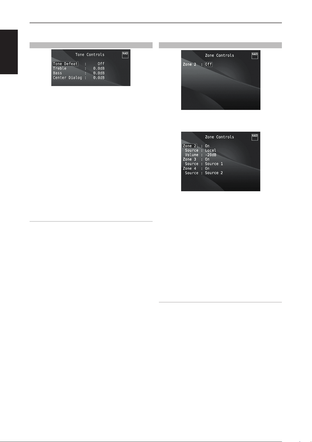
TONE CONTROLS
The M17 has three Tone Control levels – Treble, Bass and Center Dialog. Bass
and Treble controls only aect the low bass and high treble leaving the
critical midrange frequencies free of coloration. The Center Dialog (“Dialog”
in the VFD) control boosts the “presence” of the midrange region improving
intelligibility of speech.
These controls allow one to tweak on-the-y, the frequency response
of the source during playback. The control setting could be adjusted by
navigating through the Tone Controls’ OSD menu via a combination of
[ENTER] and [W/E/R/T] keys. The same can be managed directly by
pressing the front panel’s “Tone” display and then press and slide “h“ to
adjust treble, bass or dialog level.
Maximum and minimum values for all three Tone Control levels are ±10 dB.
ZONE CONTROLS
Depending on the settings made at the separate “Zone Setup” menu
under the “Setup Menu”’ section discussion, the applicable Zone can be
congured and managed via this “Zone Controls” window.
“Tone Defeat” gives one the choice of varying or completely bypassing the
tone control section of the M17. If “O” (“Tone Active” in the VFD) is selected,
the Tone Control circuits are active.
Select “On” (“Tone Defeat” in the VFD) to bypass the Tone Controls eectively
defeating the eect of the tone control circuits.
NOTE
Tone Controls options can be directly selected or changed using
HTRM2’s TONE button with DEVICE SELECTOR set to AMP mode. Toggle
TONE button to select “Treble”, “Bass” or “Dialog” and then use the
[R/T] to adjust their respective levels. Press TONE again to save the
settings and at the same time move on to the next parameter or exit the
parameter setting altogether.
Select “On” to activate the applicable Zone. When activated, the Source
input for the particular Zone can be allocated by selecting through the
following inputs – All enabled Sources and Local.
Select “Local” as your selected Zone’s Source input if you wish to enjoy the
same source as the main Zone and allow simultaneous listening, but with
full separate volume levels.
If a Zone is set to “O”, it is deactivated or powered o.
“Volume” refers to the adjustable secondary Zone 2 Volume level that can
be increased or decreased using the [R/T] buttons of the HTRM 2.
Zone 2 is always available to be congured at “Zone Controls” menu. For
Zone 3 and Zone 4 to become available at the “Zone Controls” window,
their corresponding “Mode” in the “Zone Setup” menu under the “Setup
Menu” section should be set to “Zone (Audio Only)”.
NOTES
• The ZR 7 remote control will only control Zone 2 applications. Zone 3
and Zone 4 could be congured and managed at the appropriate Zone
OSD menu using the corresponding keys on the HTRM 2 remote control.
• “Zone 4” is audio only and not associated with any video input sources.
14
Page 15
OPERATION
USING THE M17 SETUP MENU
SETUP MENU
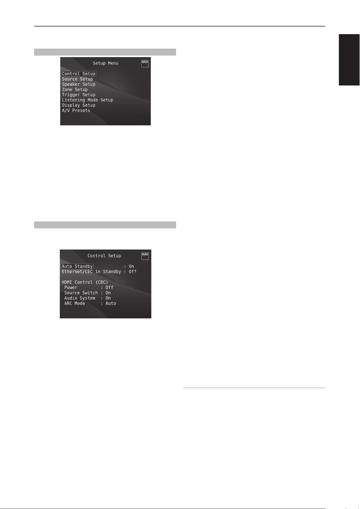
The Setup Menu allows one to customize the operation of the M17 to the
ancillary equipment used in one’s specic AV system. Unless your system
exactly matches the factory defaults as shown in the accompanying Quick
Setup Guide, you will need to use the setup menu to congure the inputs
of the M17.
At Setup Menu, the following are congurable – Control Setup, Source
Setup, Speaker Setup, Zone Setup, Trigger Setup, Listening Mode Setup,
Display Setup and A/V Presets.
To access and navigate through Setup Menu and its sub-menu selections,
please follow the directions stated in the sections “DISPLAY THE OSD” and
“NAVIGATING THE OSD AND MAKING CHANGES”.
CONTROL SETUP
The M17 supports HDMI Control (CEC) and Audio Return Channel (ARC)
functions. Both functions are possible if external devices that also support
both features are interconnected with the M17 via HDMI connection.
AUTO STANDBY
On: M17 will go to standby mode automatically if there is no user interface
interaction within 30 minutes.
O: M17 remains active even if there is no user interface interaction is
detected.
ETHERNET/CEC IN STANDBY
O : M17 will not pass through any CEC message. Audio and video will not
be streamed from a CEC-enabled HDMI source to a CEC-enabled TV (with
both devices connected via M17). CEC feature is eectively defeated.
On: Enable HDMI Control (CEC) feature. Audio and video will continuously
stream from a CEC-enabled HDMI source to a CEC-enabled TV (with both
devices connected via M17).
HDMI CONTROL CEC
Consumer Electronics Control (CEC) is a set of commands that utilizes
HDMI’s two- way communication to allow for single remote control of any
CEC-enabled devices connected with HDMI. A CEC command will trigger
the necessary commands over HDMI for an entire system to auto-congure
itself to respond to the command.
When devices that support HDMI Control (CEC) are connected, the
following modes of operation can be executed via the M17 or the external
device using any of the device’s remote control.
O: Applies to all CEC options below. At “O” setting, particular CEC feature
is defeated.
Power: At “On” setting, the M17 will automatically go to standby mode
if it receives a CEC standby command. On the other hand, if the M17
receives a CEC power up command, the M17 will correspondingly
switch ON from standby mode.
Source Switch: At “On” setting, the M17 will automatically switch
sources if another CEC device requests a Source change.
For example, if PLAY is pressed on a BD Player with CEC, the M17 and TV
with CEC will automatically switch to their respective input connections
- the M17 switching to the HDMI input where the BD Player is
connected while the TV will switch to its input where the M17’s HDMI
MONITOR OUT is connected. This completes the auto-conguration the BD Player is automatically played back using the M17 and TV.
Audio System: At “On” setting, the M17 will broadcast a CEC message
indicating it is an active audio system. A CEC compatible TV will usually
mute its audio output when this happens. When this option is enabled,
the M17 will also respond to CEC volume and mute commands. For
example, a CEC TV may forward the volume commands from its remote
to the M17.
ARC Mode: Audio Return Channel (ARC) enables an ARC-enabled TV
to send audio data “upstream” to M17.
This option has three choices: O, Auto or Source Setup.
Auto: When set to Auto, the M17 will automatically attempt an ARC
audio connection to the TV whenever the TV announces over CEC
that it has become the active source. If an ARC connection can be
established, the M17 will output the ARC audio signal no matter
what source is selected on the M17. The Auto option tends to work
best when all your devices support CEC and the Source Switch
option is set to On.
Source Setup: When set to Source Setup, you can select “ARC” for
the digital audio input in the source setup screen. When you select
a source on the M17 which is set for ARC, the M17 will attempt to
initiate an ARC connection with the TV. When using this option,
you would probably also want to make sure Source Switch is o
otherwise other CEC devices may keep changing the M17 source
when you want it to remain on the ARC source.
IMPORTANT NOTES
• “Audio System” must be set to “On” for “ARC mode” to manifest as an
option.
• Audio and video will continuously stream from the HDMI source with
CEC to the TV with CEC even if the M17 is at standby mode.
ENGLISHFRANÇAISESPAÑOLITALIANODEUTSCHNEDERLANDSSVENSKAРУССКИЙ
Ethernet connection is established when the NAD AVR Remote App is
activated and connected to the same network as the M17. Under this
condition, “Ethernet/CEC in Standby” will automatically turn from “O”
to “On”, will remain “On” and cannot be changed from “On” to “O”. The
On/O options of “Ethernet/CEC in Standby” can be selectable again by
deactivating or disconnecting the NAD AVR Remote App from the network.
15
Page 16
ENGLISH FRANÇAIS ESPAÑOL ITALIANO DEUTSCH NEDERLANDS SVENSKA РУССКИЙ
OPERATION
USING THE M17 SETUP MENU
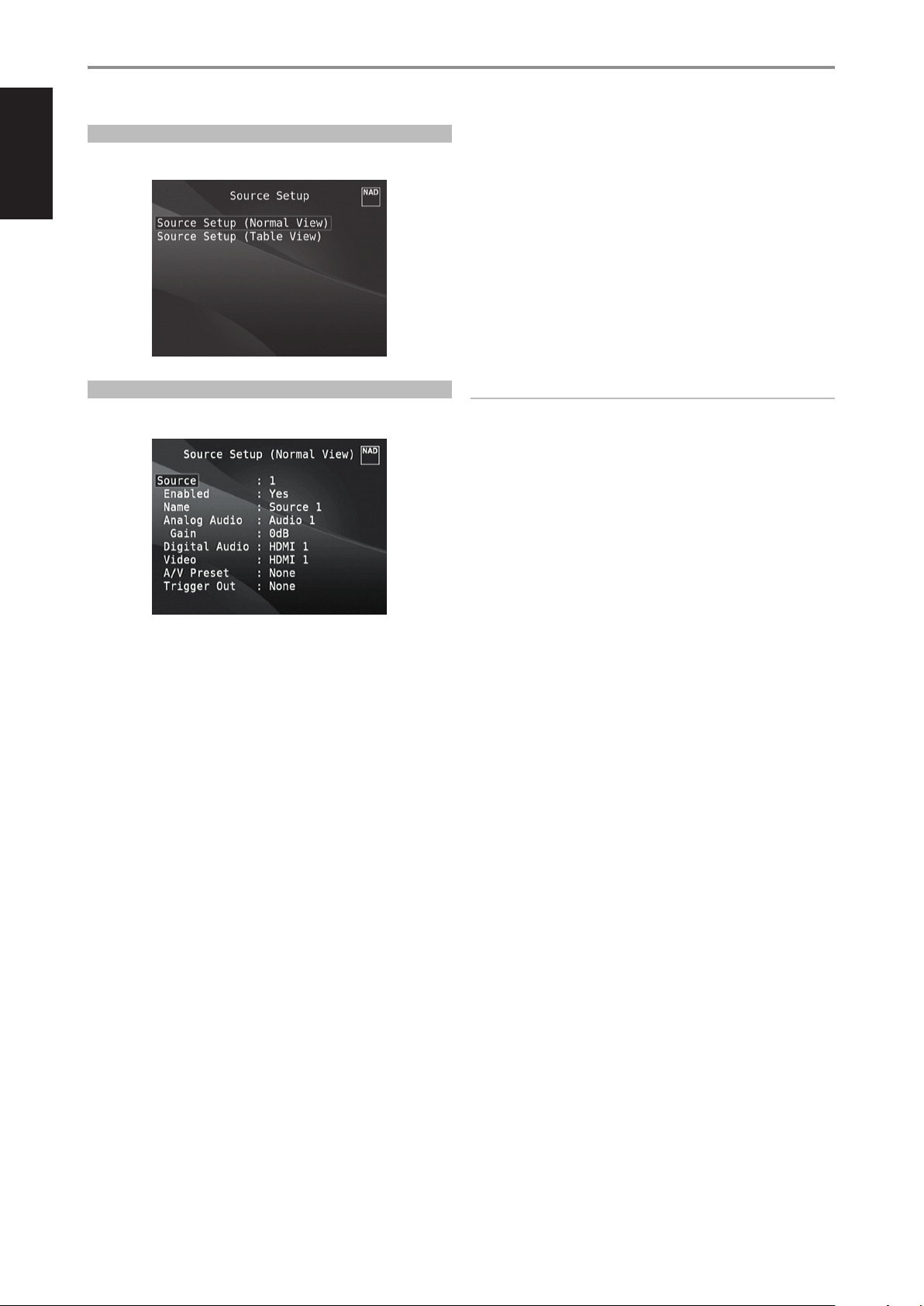
SOURCE SETUP
There are two sub-menu items under Source Setup. These are Source
Setup (Normal View) and Source Setup (Table View).
ANALOG AUDIO
All available analog audio input can be variably assigned to any of the
Sources.
Scroll to “Analog Audio”, press [E] and then [R/T] to select and assign an
analog audio input to the particular Source. There are two choices - Audio
or O.
When “Audio” is chosen, press [E] and then [R/T] to select and assign the
desired audio input -1 to 7.
If “O” is selected, no incoming analog audio signal is selected by the
particular Source. Note that when “Analog Audio” is set to “O ”, “Gain” will
not be enabled as an option.
SOURCE SETUP (NORMAL VIEW)
The Source Setup (Normal View) menu makes it possible to set, allocate or
change the following settings.
SOURCE
All available Sources are congurable. A particular Source can be enabled
or disabled, renamed, assigned analog and digital audio sources, video
sources, A/V Presets, Trigger settings among other settings.
These settings can be implemented through the following parameters.
ENABLED
One can enable/disable a Source via this option. This is particularly useful
if only few Sources are used and one directly selects the Source from the
front panel display options, bypassing unused sources.
NOTE
An incoming digital signal present at the assigned digital input will
always take precedence over the assigned analog audio input, even if
both are present. To maintain the analog audio input for the particular
Source, select “O” at the “Digital Audio” setting of the same “Source”
menu.
GAIN
Gain adjustment allows all sources to play back at the same volume level so
you don’t need to adjust the volume every time a new source is selected. It
is generally preferable to reduce the level of the loudest source rather than
making louder the softer sources.
Scroll to “Gain”, press [E] and then [R/T] to step through the desired level
from -12dB to 12dB.
Note that when “Analog Audio” is set to “O ”, “Gain” will not be enabled as
an option.
Select “Yes” to enable the particular Source or “No” to disable the Source.
NAME
A new Name maybe assigned to a Source label. For example, if your BD
player is attached to “Source 1”, it is possible to rename “Source 1” to “BD”.
In order to rename the Source label, scroll to the “Name” parameter. Press
[E] to go to the rst character. Then, press [R/T] to pick through the
alphanumeric selections.
Press [E] to move to the next character and at the same time save the
changes done on the current character. The name can be as long as twelve
characters.
The new Name will be shown in the VFD as well as on the OSD.
16
Page 17
OPERATION
USING THE M17 SETUP MENU
DIGITAL AUDIO
To take advantage of the M17’s high performance surround and digital
audio circuitry, it is advisable that its sets of Digital Audio input are selected.
There are three types of Digital Audio input for the M17. These are HDMI,
Optical and Coaxial digital input. A fourth option is “O” whereby no
incoming digital audio signal is selected by the particular Source.
The desired digital audio input for a particular Source can be selected by
scrolling to “Digital Audio”, press [E] and then [R/T] to step through the
desired digital input source. After nalizing the desired type of Digital Audio
input, press [E] and then [R/T] again to select the specic Digital Audio
input.
The following are the sets of assignable Digital Audio input:
HDMI $ HDMI 1- 6
Optical $ Optical 1-4
Coaxial $ Coaxial 1-4
NOTE
An incoming digital signal present at the assigned digital input will
always take precedence over the assigned analog audio input, even if
both are present. To maintain the analog audio input for the particular
Source, select “O” at the “Digital Audio” setting of the same “Source”
menu.
VIDEO
There are three types of video input a particular Source could be assigned.
These are HDMI, Component and Video input. Another option is “O”. Select
“O” if it is intended not to assign any video input to a particular Source.
Navigate through the Video input selections by pressing [E] and then
[R/T] to step through the selections. The following are the sets of
assignable Video input.
TRIGGER OUT
Trigger Out feature for a particular Source is dependent upon the
congurations done in a separate menu on Trigger Setup (See “Trigger
Setup” below). If “Source Setup” is assigned to all three Trigger output
(Trigger Out 1-3) in the separate “Trigger Setup” menu window, a particular
Source can have the following Trigger Out combinations
Trigger Out: 1 $ 2 $ 1 + 2 $ 3 $ 1 + 3 $ 2 + 3 $ 1+2+ 3
These combinations are dependent upon the assignment of “Source Setup”
for Trigger 1 Out, Trigger 2 Out or Trigger 3 Out at the “Trigger Setup” menu.
Another option is “None” whereby the particular Source is not assigned any
Trigger Out.
For “Trigger Out” to become enabled and assignable at “Source Setup
(Normal View)” menu, make sure to carry out or note the following
beforehand
• In the separate “Trigger Setup” menu, assign Trigger 1 Out, Trigger 2 Out
or Trigger 3 Out to “Source Setup.”
• “Trigger Out” will not appear as an option at the Source Setup (Normal
View) menu if at the separate “ Trigger Setup” menu, Trigger 1 Out,
Trigger 2 Out or Trigger 3 Out are all assigned to “Main, Zone 2, Zone3,
Zone 4, Zone 2+3+4, Main + Zone 2, Main + Zone 3, Main + Zone 4
or Main + Zone 234”; with not even one “Trigger Out” port allocated to
“Source Setup.”
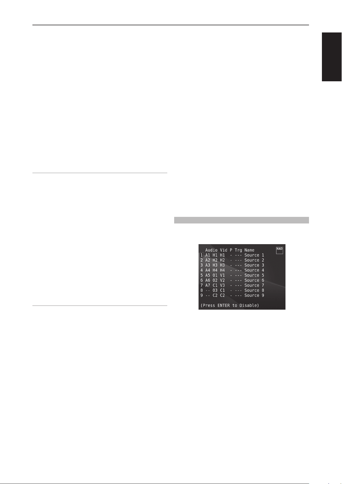
SOURCE SETUP (TABLE VIEW)
The Source Setup (Table View) reects the settings made in the Source
Setup (Normal View) menu. All the Source settings are summarized and
displayed in tabulated form in the Source Setup (Table View).
ENGLISHFRANÇAISESPAÑOLITALIANODEUTSCHNEDERLANDSSVENSKAРУССКИЙ
HDMI $ HDMI 1-6
Component Video $ Component 1 - 2
Video $ Video 1 - 3
Previous $ Display or retain preceding video.
IMPORTANT NOTE ABOUT THE VIDEO PERFORMANCE OF M17
The M17 utilizes an NAD-engineered eld-programmable gate array
(FPGA) that is capable of enabling the conversion of analog video to
digital video. This allows a single cable connection to your TV for all
sources while maintaining the source’s native resolution. Interlaced
video is converted to progressive scan over HDMI allowing complete
compatibility with latest HD TVs.
The M17 also supports HDMI 1.4a features that include compatibility with a
broad range of 3D and HD digital video sources and displays.
A/V PRESET
A particular Source can be assigned a stored Preset. The parameters set up
in the selected Preset number will be adopted into the particular Source it
is assigned (Please refer to the separate section on “A/V Presets” for further
understanding of Preset settings).
Scrolling to “A/V Preset” and by pressing [E] and then [R/T], a Source
could be assigned a Preset number ranging from Preset 1 to 5.
If it is desired not to assign the particular Source a Preset setting, select
“None”.
Navigating through the Source Setup (Table View) via a combination
of [W/E] and then [R/T] buttons, one will have the benet of directly
changing the settings for “Audio”, “Video”, “Preset”, “Trigger” and “Name”
without going back to the Source Setup (Normal View) menu.
Highlight a particular Source number and then, toggle [ENTER] button to
enable or disable said Source number.
17
Page 18
ENGLISH FRANÇAIS ESPAÑOL ITALIANO DEUTSCH NEDERLANDS SVENSKA РУССКИЙ
OPERATION
USING THE M17 SETUP MENU
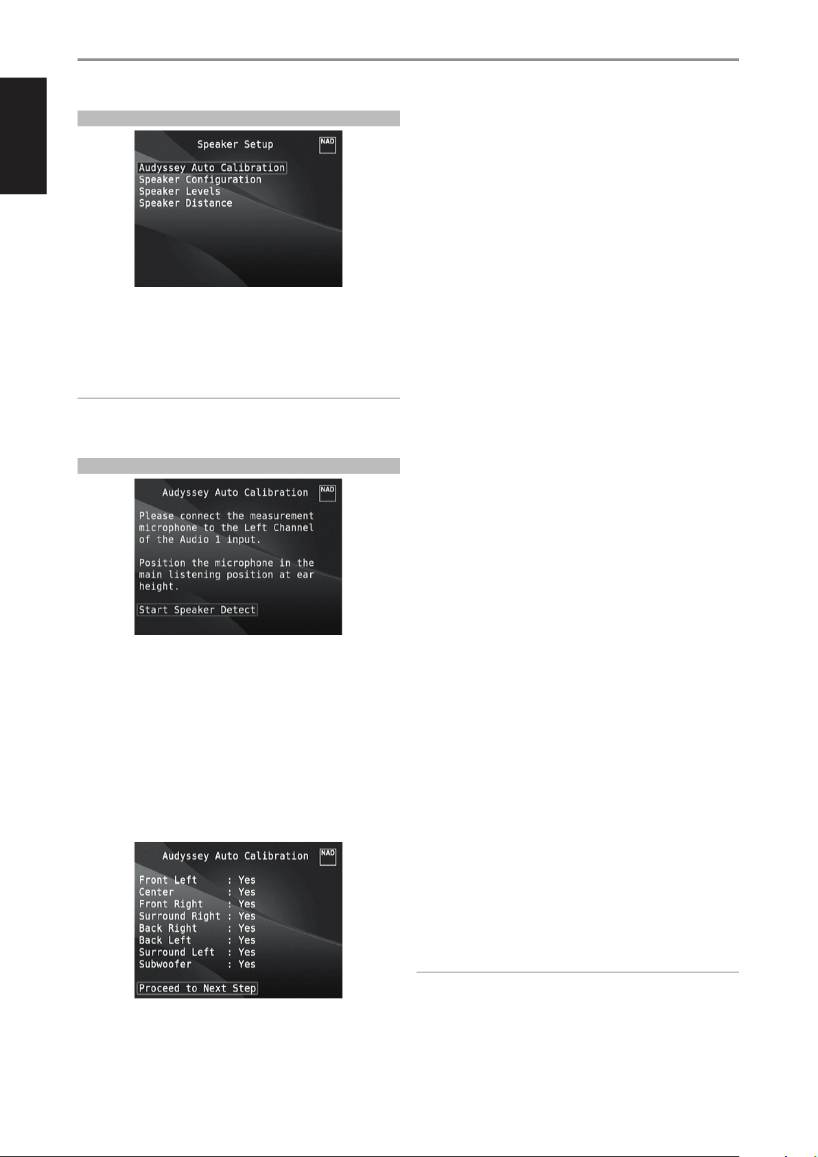
SPEAKER SETUP
After connecting all ancillary sources and other combinations, the Speaker
Setup menu will guide you on how to manage and setup your speakers in
order to achieve optimum sound acoustics in your listening environment.
The following are the Speaker Setup Menu sections.
IMPORTANT NOTICE
The M17 is an AV Surround Sound Preamplier and therefore has no
speakers. The mention of “Speaker(s)” in this manual refers to the
speakers of your external amplier as interfaced with the M17.
AUDYSSEY AUTO CALIBRATION
The following measurements are performed:
• Detection: Speaker conguration is detected including number of
surround speakers and whether a subwoofer and center channel is
connected.
• Size: M17 crossover is set based on each channel’s signal handling
capability and the subwoofer crossover is automatically set.
• Level: SPL of each speaker is matched within 1dB at the microphone
position.
• Distance: This is accurately set to within 1 foot (30 centimeters) of the
microphone for each speaker position.
• Polarity: The setup program will detect and notify the user if any
speakers are connected improperly. Incorrect polarity can ruin the
illusion of realism oered by surround sound.
This is a one-time set up, unless speakers are moved or changed, in which
case the calibration should be performed again.
AUDYSSEY MultEQ XT ROOM ACOUSTICS CORRECTION
Sound reecting from room boundaries can disturb the spatial illusion
of surround sound, and can also distort the tonal balance of the system.
Professional Acoustical Engineers often add wall treatments and even move
walls and relocate speakers to improve system performance, but for the
average Home Theatre, this is either too expensive or just not a practical
solution.
It has been shown that many, if not most, surround sound systems are not
accurately setup and calibrated. To conduct properly, calibration requires
special knowledge and instrumentation that the average person probably
doesn’t possess.
The Audyssey Auto Setup and Calibration featured in M17 uses a
microphone, along with sophisticated digital electronics built into your
M17, to automatically setup and calibrate the M17 to the exact speakers
and speaker placement of your own unique Home Theatre.
The Left Channel of AUDIO 1 IN is the assigned port where the supplied
3.5mm female jack to RCA plug Adapter can be connected. Plug in the
Audyssey microphone into the adapter for Audyssey Auto Calibration.
Audyssey MultEQ XT features adaptive low-frequency correction and uses
16x high-resolution equalization lters for satellites and subwoofers. Using
multiple measurements from actual listening positions, and processing
this information with sophisticated digital signal processing, Audyssey
MultEQ XT is able to “precondition” the signal to eectively make the walls
disappear. This creates a “family size” sweet spot where the sound and
spatial cues are very accurately reproduced.
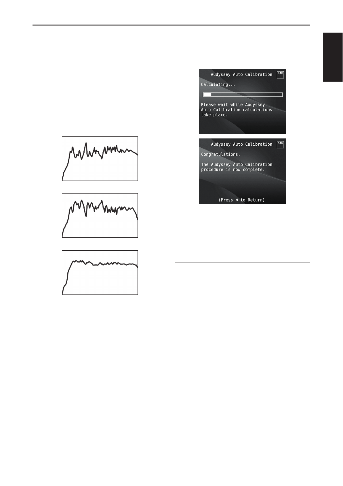
The Audyssey Auto Calibration wizard will guide you through a simple
step-by-step conguration. Once setup and calibrated, the next greatest
improvement in performance is obtained by eliminating the acoustic
interference caused by room boundaries interacting with your speakers.
MEASUREMENT IS THE FIRST STEP
The sound at each listening position (up to 8 positions) is calibrated using
the same microphone used during the setup phase.
A special test tone is sent to each speaker and the data is memorized by
the M17. The duration of calibration may take some time depending on
the number of speakers as well as the number of measuring points. After
all positions are measured, the DSP calculates the ideal system response for
your particular room and speaker setup.
If some inconsistencies or discrepancies are detected during the Audyssey
calibration, the process maybe interrupted or the problem is shown in the
particular setup window. A notice screen is correspondingly displayed.
After following and undertaking the displayed instructions, re-start the
Audyssey calibration again. When the measurements are nalized, Audyssey
calculates the ideal system response for your particular room and speaker
setup.
18
NOTE
The test tone emitted during measurement is loud. If you cannot
withstand the test tone level, it is advisable that you stay away from
the room or location where the speakers are being calibrated. Return to
the room or location after each calibration to change the microphone’s
position or to nalize the calibration.
Page 19
OPERATION
USING THE M17 SETUP MENU
NEXT A TARGET CURVE MUST BE CHOSEN
Because loudspeaker designers assume that their products will be used in
typical domestic rooms, they are “voiced” to work in this environment. It is
assumed that the room will add some bass reinforcement and will absorb
some treble energy. Thus if we eectively “remove the walls” with room
correction, and set the speakers for at response, you may nd this sounds
too bright in the treble and too weak in the bass region.
NAD engineers have done extensive research in this area of room acoustics,
and along with Audyssey engineers developed what we believe is the ideal
‘“in room” response curve. We include this NAD EQ, along with an Audyssey
developed EQ as the two best choices. The response curves shown below
typify NAD EQ room correction process.
Room Response measured by Audyssey microphone
Inverse Correction Filter calculated by NAD M17
Select the Target Curve you nd to be most satisfactory by pressing the
Audyssey key of the remote. The MultEQ XT corrected response can also be
bypassed if you wish.
It is recommended that you take full advantage of the M17’s Audyssey Auto
Calibration feature for your speaker setup. However, if you desire to setup
your speakers manually or if you already had run Audyssey Auto Calibration
but would like to make adjustments, the following sections on Speaker
Conguration, Speaker Levels and Speaker Distance can also be followed
and implemented.
ENGLISHFRANÇAISESPAÑOLITALIANODEUTSCHNEDERLANDSSVENSKAРУССКИЙ
Corrected Room Response
Flat EQ is a third option, but not one that we recommend for listening
(it is useful for verifying system performance when using external
instrumentation).
NOTE
During manual setting of your speakers, previously calibrated
Audyssey settings could be retrieved by re-adjusting back the altered
congurations as highlighted by an asterisk.
19
Page 20
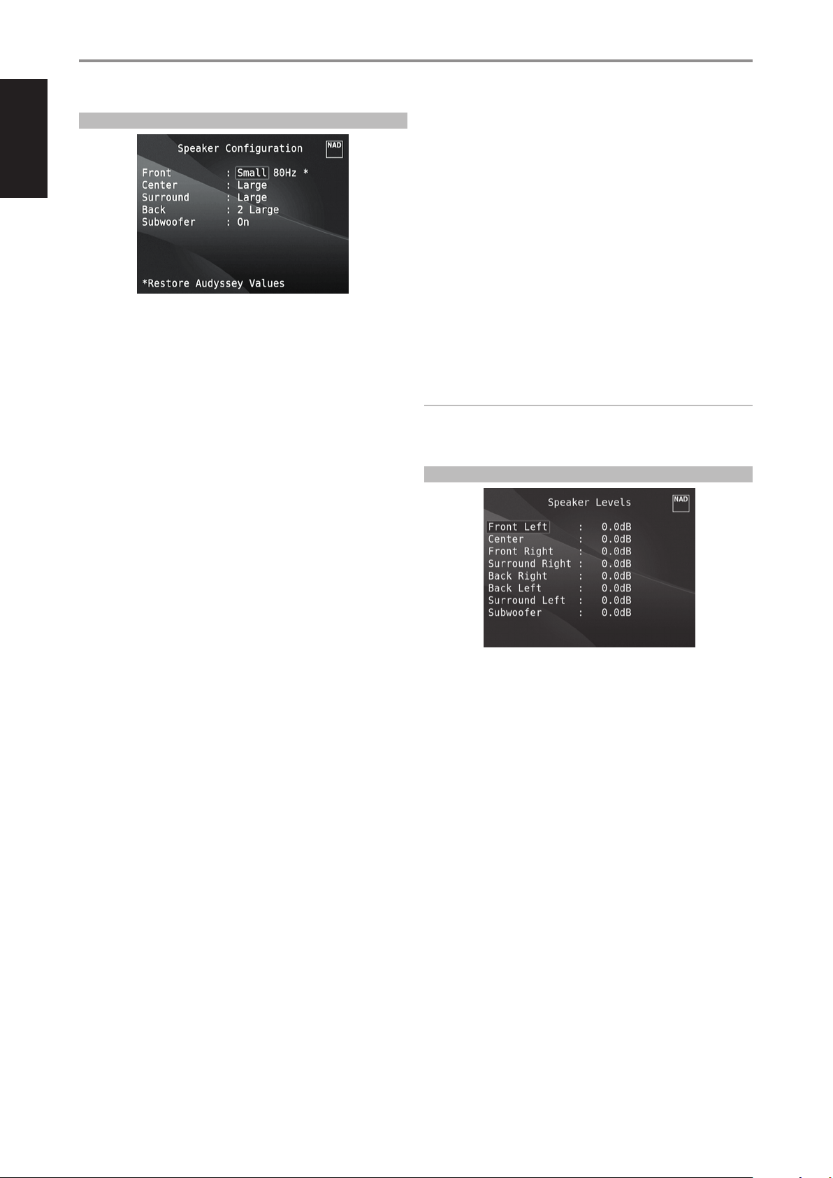
ENGLISH FRANÇAIS ESPAÑOL ITALIANO DEUTSCH NEDERLANDS SVENSKA РУССКИЙ
OPERATION
USING THE M17 SETUP MENU
SPEAKER CONFIGURATION
Every surround-sound system requires “bass-management” to direct lowfrequency content from any or all channels to the speakers best able to
reproduce it. For this function to operate correctly, it is important that you
correctly identify your speakers’ capabilities. We use the terms “Small” and
“Large” (and “O”) but note that physical size may be irrelevant.
• A “Small” speaker is any model, regardless of physical size, that lacks
signicant deep-bass response, that is, below about 200 Hz.
• A “Large” speaker is any full-range model; that is, one with deep-bass
response
• An “O ” speaker is one that is not present in your system. For example,
you might not have any surround-back speakers installed; in that case,
you would set the “Surround” setup item to “O”.
ENHANCED BASS
When the subwoofer is set to “On” and “Front” is set to “Large”, the option
“Enhanced Bass” becomes available. Normally, with speakers set to “Large”
the subwoofer is not active. The Enhanced Bass option allows full range
operation of the speakers with the additional bass contribution of the
subwoofer. This feature is particularly useful when one wants to experience
maximum bass output. Please note that due to acoustic cancellation
eects, the bass response may be uneven when using this setting.
You can set Subwoofer to “On” even with “Large” front speakers, in which
case bass content from any channels set to “Small” will be routed to both
the subwoofer and to the front speakers; LFE-channel signal will pass only
to the sub. In most subwoofer-equipped systems, setting front speakers to
“Small” is usually the better option.
All the speakers’ low frequency content can be directly adjusted within the
range 40Hz to 200Hz.
NOTE
The congurations set forth at ‘Speaker Setup’ are carried over whenever
it is enabled during A/V Preset setting. Please see also the section “AV
Presets” for reference.
SPEAKER LEVELS
The Speaker Conguration is “global”; that is, it remains in force with all
input and listening modes. However, speaker settings are part of the M17’s
Preset system. Consequently, multiple speaker settings can be stored for
easy recall as dierent types of recordings or listening modes require.
Speaker Conguration can be managed and adjusted by pressing
a combination of [E] and then [R/T] keys. Set “Front”, “Center” and
“Surround” to “Large”, “Small”(40Hz to 200Hz) or “O” as your subsystem’s
speakers require.
The “Back” speakers can either be one or two speakers. Set “Back” to either
1 or 2 speakers as per availability. Set “Subwoofer” to “On” or “O” selecting
“On” only if you have a subwoofer connected to the M17’s SUBW1 or SUBW2
output jack. If “Subwoofer” is set to “O”, “Front” speakers will automatically
be set to “Large”.
Adjusting the relative balance of your system’s loudspeakers ensures that
surround-sound recordings, whether music or lm, will present the balance
of eects, music, and dialog that the artists intended. Additionally, if your
system incorporates a subwoofer it establishes a correct relationship
between the volume of the subwoofer and the other speakers, and thus of
low-frequencies (bass) to other sonic elements.
USING AN SPL METER
It is quite practical to perform the M17 level setup routines “by ear,” and
careful work will produce acceptably accurate results. However, the use
of an inexpensive sound-pressure level (SPL) meter, such as Radio Shack
part number 33-2050, makes this task easier, more accurate and more
repeatable. Ownership of such a meter could prove a valuable audio tool.
The SPL meter should be placed at the primary listening position, at
approximately the height of the seated listener’s head. A tripod is helpful
but with a little duct tape almost anything - a pole lamp, music-stand,
or ladder-backed chair, for example -can do as well. Just be sure that no
large acoustically reective surfaces obstruct or are near the microphone
element.
20
Orient the meter with its microphone (usually at one end) pointing straight
up toward the ceiling (not toward the speakers) and ensure that “C”
weighting scale is selected. Set the meter to display 75 dB SPL. On Radio
Shack meters, this necessitates either setting the meter to its 80 dB range
and taking your readings at the -5 point or selecting the 70 dB range and
reading at the +5 point.
Page 21
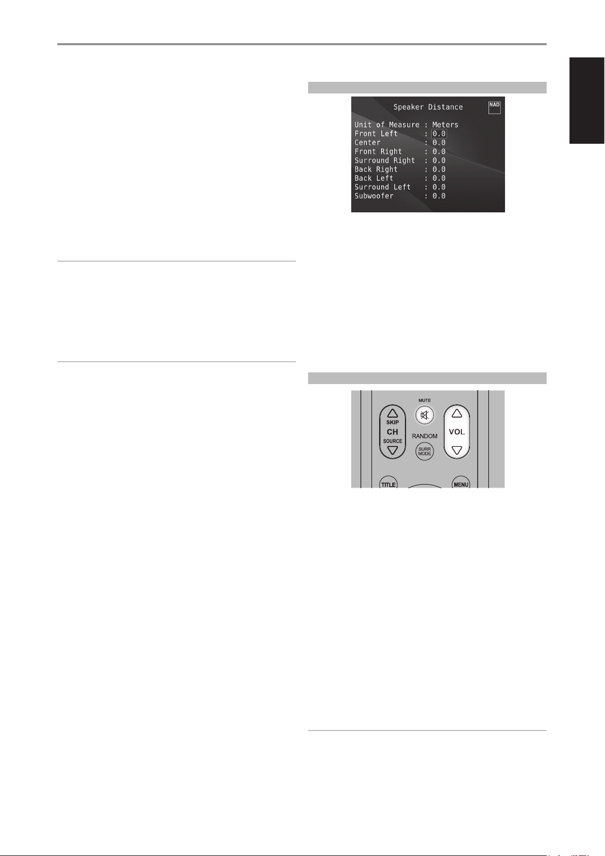
OPERATION
ON
OFF
SOURCE
MMUUTTEE
DAC
DEVICE SELECTOR
MP
USING THE M17 SETUP MENU
SETTING SPEAKER LEVELS AT TEST MODE
While at “Speaker Levels” menu, press the HTRM 2 remote’s [TEST] key
activating the M17’s Speaker Levels balancing test signal. You will hear a
“surf” sound as you step through your speakers (“test” appears to the right
side of the current speaker), beginning with the Front Left. If you do not
hear the test signal, check your speaker connections or your “Speaker Setup”
OSD menu settings.
Use the remote’s [R/T] keys to adjust the loudness of the noise output
from the currently playing channel to the required level (it’s usually
simplest to begin with the Front Left). As you cycle the test signal around
the speakers, the OSD will highlight the currently playing channel. The
“level oset” reading on the right will change by 0.5dB increments; ±12 dB
adjustment is available. Press “ENTER” to adjust the next speaker.
NOTE
If you are balancing levels “by ear”, choose one speaker—usually the
center—as a reference and adjust each of the others in turn to “sound as
loud” as the reference. Be sure that you remain in the primary listening
position while balancing all channels.
To produce the same SPL meter reading (or subjective loudness), use the
remote’s [R/T] keys to adjust each speaker.
NOTES
• All speakers must be in their nal locations before level-setting.
• Your subwoofer (if any) should be set with its integral crossover defeated,
or if undefeatable, set to its highest-possible frequency if you are using
the M17’s Subwoofer output. Final subwoofer-level adjustment “by-ear,”
using music and lm sound material, is frequently useful.
• Due to the eects of room acoustics, matched-pair speakers (front;
surround; back) will not always calibrate to exactly the same level oset
readings.
SPEAKER DISTANCE
ENGLISHFRANÇAISESPAÑOLITALIANODEUTSCHNEDERLANDSSVENSKAРУССКИЙ
Your system’s speaker distance settings are a subtle but important
renement of your setup. Informing the M17 of the loudspeaker-to-listener
dimensions of each speaker automatically imposes the correct delays,
optimizing imaging, intelligibility and surround-sound ambience. Enter your
dimensions with precision within about 1 foot (30 cm).
SETTING SPEAKER DISTANCE
While at “Speaker Distance” menu, use the [R/T] keys to individually
set Front Left, Center, Front Right, Surround Right, Back Right, Back Left,
Surround Left and Subwoofer to the distance measuring from your
principal listening position to the front surface of their corresponding
loudspeakers. Distance can be set up to 30 feet or 9.1 meters Distance can
be displayed as feet or meters selectable at the “Unit of Measure” item.
ADJUSTING THE VOLUME
You can exit “Test” mode at any time by pressing [W] key, bringing you back
to “Speaker Setup” menu. You can also press the [TEST] key to discontinue
the “Test” mode.
In addition to the Volume knob, use the HTRM 2’s [ VOL R/T] to adjust the
“master volume” of the M17 raising or lowering the channels altogether. A
momentary key press will change the master volume by 0.5dB increments.
If you hold down [VOL R/T], the master-volume change will “run-on” until
the key is released.
Since recordings vary considerably in overall average level, there is no
imperative to listen at any particular master-volume setting. A setting of
-20.0 dB may sound “as loud” from one CD or DVD as -10.0 dB does from
another.
The M17 will power-up from Standby mode at whatever master volume
setting was last used; however, if the prior setting was greater than -20.0 dB,
the M17 will power up at -20.0 dB. This prevents inadvertently beginning a
session at excessive volume.
MUTING THE SOUND
Use the HTRM 2’s [MUTE] key to silence all channels completely. Muting is
always available regardless of the source or listening mode selections.
NOTES
• Changing input or listening-mode selections does not release muting.
• Pressing HTRM 2’s [ VOL R] or rotating the front panel volume knob
clockwise will automatically release the mute function.
21
Page 22
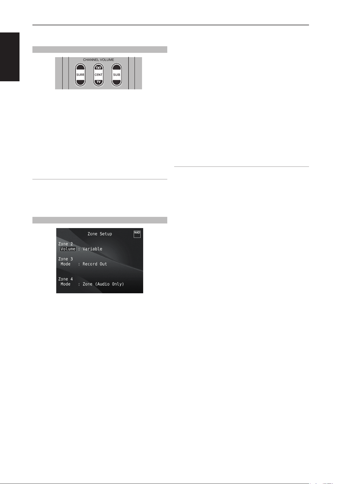
ON
OFF
SOURCE
10
IN
SSEETTUUPP DDEELLAAYY // PPIICCTTUURREE TTEESSTT // ZZOOOOMM
EEQQ TTOONNEE LL..NNIITTEE
DDIIMMMMEERR
CHANNEL VOLUME
8
IN
MMUUTTEE
PPRROOGGRRAAMM CCLLEEAARR RREEPPEEAATT
DAC
DEVICE SELECTOR
MP
SSLLEEEEPP
ENGLISH FRANÇAIS ESPAÑOL ITALIANO DEUTSCH NEDERLANDS SVENSKA РУССКИЙ
OPERATION
USING THE M17 SETUP MENU
ADJUSTING CHANNEL LEVELS “ON THE FLY’
You can make changes to the relative levels of center, surround and
subwoofer outputs without having to go into the
“Speaker Levels” menu. This is very convenient in circumstances like
increasing (or tone down) a lm’s dialog level by raising (lowering) the
center channel or reducing excessive deep bass (or enhance deep bass) by
lowering (raising) the subwoofer level.
Use the HTRM 2’s “SURR”, “CENT” and “SUB” keys for direct-access level
adjustment of these channels over a range of ±6 dB.
The surround back channels (if any) adjust in lockstep with the surround
channels.
NOTE
Level settings adjusted “On the Fly” are added or subtracted to the setup
levels established at the M17 level-calibration routine as invoked by the
HTRM 2 [Test] key. However, selecting any Preset will revert the channel
levels to those stored in the preset. It will also take M17 o the levels set
via Audyssey Auto Calibration.
VOLUME
Zone 2 have Fixed and Variable volume control. When set to “ Variable” and
while at the “Zone Controls” menu OSD, the Zone 2 Volume level can be
adjusted using the HTRM 2’s [R/T] or directly via ZR 7’s [ VOL d/f].
On the other hand, if Volume is set to “Fixed”, the Zone 2 Volume is set to
a preset dB level and thereafter the Zone’s volume can be varied via the
volume control of the separate amplier it is fed into.
MODE
Zone 3 and Zone 4 can be congured into two modes - Record Out and
Zone (Audio Only). If the selected mode is “Record Out”, the audio of the
assigned Source is directly sent out to the applicable Audio output. When
Zone 3 or Zone 4 is set to “Record Out” mode, they will not be available at
the “Zone Controls’ section of the Main Menu window.
See discussion also on “Zone Controls” at the Main Menu.
NOTE
The ZR 7 remote control will only control Zone 2 applications.
ZONE SETUP
The Zone feature allows one to simultaneously experience in dierent
zones of the house multiple sound sources from all enabled Sources.
The M17 has three congurable Zones – Zone 2, Zone 3 and Zone 4. Use
a combination of [W/E/R/T] and [ENTER] keys to navigate through the
Zone Setup menu parameters.
22
Page 23
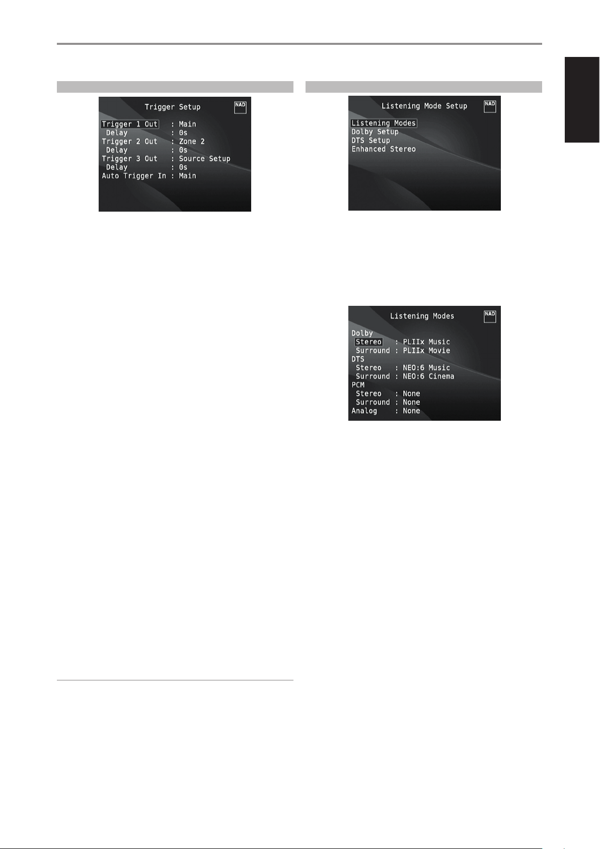
OPERATION
USING THE M17 SETUP MENU
TRIGGER SETUP
The M17 features three congurable +12V DC Trigger Output that can be
used to activate a component or system it is fed into. A Trigger Input is also
available to turn on the applicable link it is associated to. Use a combination
of [W/E/R/T] and [ENTER] keys to navigate through the Trigger Setup
menu parameters.
TRIGGER OUT
Triggers are low voltage signal used to turn on/o other compliant devices.
The M17’s three +12V DC Trigger Output (Trigger 1 Out, Trigger 2 Out and
Trigger 3 Out) are dependent upon the mode they are associated with. The
following are the choices where +12V DC output can be assigned.
Main: +12V DC is available at the assigned Trigger Out when the M17 is
at powered state.
Zone 2, Zone 3, Zone 4, Zone 2+3+4: When the applicable Zone is at
powered state, +12V DC is available at the assigned Trigger Out.
Main+Zone 2, Main+Zone 3, Main+Zone 4, Main+Zone 234:
+12V DC is available from Trigger Out when either the M17 or the
applicable Zone is powered up.
Source Setup: If Trigger Output is linked to “Source Setup”, +12V DC
is available at Trigger Out whenever the particular assigned Source is
selected. Please see also separate discussion about “ Trigger Out” under
the Source Setup (Normal View) section.
DELAY
The availability of +12V DC at Trigger Out can be regulated. If it is desired
that +12V DC is available without delay the moment Trigger Out is linked
to its assigned setting, set Delay to 0s. Otherwise, one can select through a
delay time of 1s to 15s.
AUTO TRIGGER IN
Auto Trigger IN allows external system controllers to toggle the associated
section of the M17 from “Standby” to “On” and vice versa. When the +12V
TRIGGER IN switch at the rear panel is set to AUTO, a +12V DC input at
Trigger IN will power ON the section where Trigger IN is assigned.
Main: From standby mode, the M17 is powered ON when +12V DC is
applied at Trigger IN.
Zone 2, Zone 3, Zone 4: Applicable Zone is turned ON whenever
+12V DC is present at Trigger IN.
All: Main, Zone 2, Zone 3 and Zone 4 as described above will all be
activated given a +12V DC input at Trigger IN.
LISTENING MODE SETUP
ENGLISHFRANÇAISESPAÑOLITALIANODEUTSCHNEDERLANDSSVENSKAРУССКИЙ
The M17 has various listening mode options and is mostly congurable.
These are provided to reproduce a variety of sound eects depending upon
the content of the source to be played. Use a combination of [W/E/R/T]
and [ENTER] keys to congure the following settings.
LISTENING MODES
The audio format as detected by the selected Source can be automatically
congured and processed through the following options:
DOLBY
Dolby Digital is the multi-channel digital signal format developed in the
Dolby laboratories. Discs bearing the Dolby Digital (double-D symbol) logo
were recorded with up to 5.1 channels of digital signals, reproducing a
much better sound quality, with dynamic and spatial sound sensations that
are much better than in the previous Dolby Surround.
A Dolby Digital audio input can be congured relative to its format as
follows
Stereo: If the detected audio is of Dolby stereo format, you can default
it to one of the following settings - Pro Logic, PLIIx Movie, PLIIx Music or
None.
Surround: If the detected audio is of Dolby Surround format, you can
default it to one of the following settings - Surround EX, PLIIx Movie,
and PLIIx Music, Stereo Downmix or None.
None: If “None” is selected, the Dolby Digital signal will be defaulted
to the “Stereo” or “Surround” settings set forth at the “PCM” option. See
discussion below about “PCM”
WARNING
If “Auto Trigger In” at Trigger Setup menu is assigned to “Main” or “All”
and the +12V TRIGGER IN switch is set to “AUTO” mode, the (Standby)
button in the front panel as well as the corresponding ON/OFF function
keys in the HTRM 2 remote control will be disabled eectively handling
this function to an external controller. Slide to “OFF” the +12V TRIGGER
IN switch to maintain normal power ON/OFF function procedures.
23
Page 24

ENGLISH FRANÇAIS ESPAÑOL ITALIANO DEUTSCH NEDERLANDS SVENSKA РУССКИЙ
OPERATION
USING THE M17 SETUP MENU
DOLBY DIGITAL PLUS
Dolby Digital Plus is the next-generation audio technology for all highdenition programming and media. It combines the eciency to meet
future broadcast demands with the power and exibility to realize the full
audio potential expected in the upcoming high-denition era.
Dolby Digital Plus delivers multi-channel audio programs of up to 7.1
channels and supports multiple programs in a single encoded bit stream
with the maximum bit rate potential of up to 6 Mbps and the maximum bit
rate performance of up to 3 Mbps on HD DVD and 1.7 Mbps on Blu-ray Disc.
It output Dolby Digital bit stream for playback on existing Dolby Digital
systems. Dolby Digital Plus can accurately reproduce the sound originally
intended by directors and producers.
It also features multi-channel sound with discrete channel output,
interactive mixing and streaming capability in advanced systems.
Supported by High-Denition Media Interface (HDMI), a single-cable digital
connection is possible for high-denition audio and video.
DOLBY TrueHD
Dolby TrueHD is a lossless encoding technology developed for highdenition optical discs in the upcoming era. Dolby TrueHD delivers
tantalizing sound that is bit-for-bit identical to the studio master, unlocking
the true high-denition entertainment experience on high-denition
optical discs in the next generation. When coupled with high-denition
video, Dolby TrueHD oers an unprecedented home theater experience
with stunning sound and high-denition picture.
It supports bit rates of up to 18 Mbps and records up to 8 full-range
channels individually with 24-bit/96 kHz audio. It also features extensive
metadata including dialogue normalization and dynamic range control.
Supported by High-Denition Media Interface (HDMI), a single-cable digital
connection is possible for high-denition audio and video. HD DVD and
Blu-ray Disc standards currently limit their maximum number of audio
channels to eight, whereas Dolby Digital Plus and Dolby TrueHD support
more than eight audio channels. Note that the M17 only supports 7.1
channel.
DOLBY DIGITAL EX
Using a Matrix decoder, this method creates the back channel (sometimes
also called the “surround center”) by means of signals on the left and
right surround channels recorded in Dolby Digital 5.1, reproduction being
provided in Surround 6.1. This method should be selected with sources
bearing the “Dolby Digital (double-D symbol)-EX” symbol, recorded in Dolby
Digital Surround EX.
DTS
The Digital Theater System Digital Surround (simply called DTS) is a multichannel digital signal format that can process higher data rates than with
Dolby Digital. Although both Dolby Digital and DTS are 5.1 channel media
formats, discs bearing the “DTS” symbol are thought to provide better sound
quality due to the lower audio compression required. It also oers a broader
dynamic, producing magnicent sound quality.
A DTS audio input can be congured relative to its format as follows
Stereo: If the detected audio is of DTS format, you can default it to one
of the following settings - NEO:6 Cinema, NEO:6 Music or None.
Surround: If the detected audio is of DTS Surround format, you can
default it to one of the following settings - NEO:6 Cinema, NEO:6 Music,
Stereo Downmix or None.
None: If “None” is selected, the DTS signal will be defaulted to the
“Stereo” or “Surround” settings set forth at the “PCM” option. See
discussion below about “PCM”.
NOTE
Please refer to the section “Listening Mode” at the Main Menu
discussions for a description of Stereo Downmix and DTS NEO:6
surround modes.
PCM
PCM (Pulse Code Modulation) is the digital representation of a standard
audio signal converted with little or no compression. If “None” is selected
for any of the Dolby or DTS settings, this “PCM” section will default the audio
signal as follows
Stereo: The detected stereo audio format will be congured into one
of the following options - Pro Logic, PLIIx Movie, PLIIx Music, NEO:6
Cinema, NEO:6 Music, EARS, Enhanced Stereo or None.
Surround: The detected surround audio format will be congured into
one of the following options - PLIIx Movie, PLIIx Music, NEO:6 Music,
NEO:6 Cinema, Stereo Downmix or None.
ANALOG
If the audio input is an analog signal, the following are the surround modes
the input can be defaulted - Pro Logic, PLIIx Movie, PLIIx Music, NEO: 6
Cinema, NEO: 6 Music, EARS, Enhanced Stereo and None.
With this additional channel you will experience improved dynamics and
a better sensation of movement within the sound eld. If media sources
recorded in Dolby Digital EX are decoded with a Digital EX decoder,
the format is detected automatically, and the Dolby Digital EX mode is
selected. However, some media sources recorded in Dolby Digital EX can be
detected as simple Dolby Digital media sources. In this case Dolby Digital
EX should be selected manually.
NOTE
Please refer to the section “Listening Mode” at the Main Menu
discussions for a description of Pro Logic, PLIIx Movie, PLIIx Music and
Stereo Downmix modes.
24
Page 25
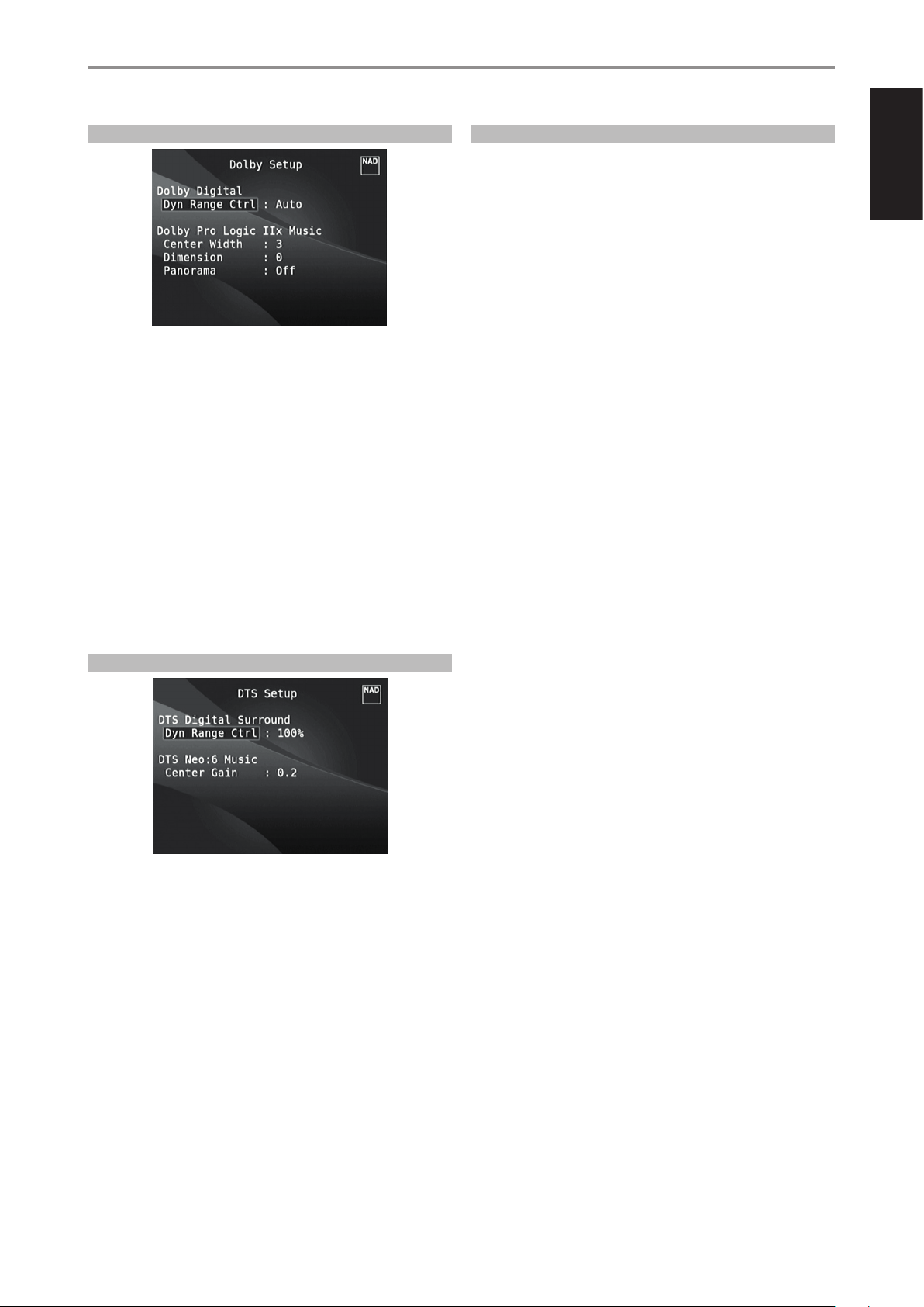
OPERATION
USING THE M17 SETUP MENU
DOLBY SETUP
Under this menu, the Dolby Digital’s Dynamic Range Control can be
adjusted as well as the settings for Dolby Digital Pro Logic IIx Music.
Dyn Range Ctrl: You can select the eective dynamic range (subjective
range from soft to loud) for playback of Dolby Digital soundtracks. For
fully cinematic eect, always select 100%, the default. Settings of 75%,
50%, and 25% progressively reduce dynamic range, making soft sounds
comparatively louder while limiting the peak loudness of loud ones.
The 25% setting will yield the least dynamic range and is best for latenight sessions or other times when you wish to retain maximum dialog
intelligibility while minimizing overall volume levels.
For Dolby TrueHD sources, set the Dynamic Range Control to “Auto”.
DTS SURROUND MODES
The following are further descriptions about the DTS surround modes.
DTSHD MASTER AUDIO
DTS-HD Master Audio is a technology that delivers master audio sources
recorded in a professional studio to listeners without any loss of data,
preserving audio quality. DTS-HD Master Audio adopts variable data
transfer rates, facilitating data transfer to the maximum rate of 24.5 Mbps
in the Blu-ray disc format, 18.0 Mbps in the HD-DVD format, which by
far exceeds that of a standard DVD. These high data transfer rates enable
lossless transmission of 96 kHz/24-bit 7.1-channel audio sources without
deteriorating the quality of the original sound. DTS-HD Master Audio is an
irreplaceable technology that can reproduce sound faithfully as intended
by the creator of music or movies.
DTS ES EXTENDED SURROUND ™ DTS ES
This is a new multi-channel digital format which greatly improves the 360°
spatial sensation of the Surround impression thanks to the greater space
expansion of the surround signals, providing high compatibility with the
conventional DTS format.
In addition to the 5.1 channels, the expanded DTS-ES Surround also
oers the back surround (also sometimes called the “surround center”)
in reproduction, providing a total of 6.1 channels. The expanded DTS-ES
Surround includes two formats, with two dierent methods of surround
signal recording, as follows:
ENGLISHFRANÇAISESPAÑOLITALIANODEUTSCHNEDERLANDSSVENSKAРУССКИЙ
Dolby Pro Logic IIx Music: Please refer to the same description of
“PLIIx Music” under the “ADJUSTING LISTENING MODES” segment of the
“OPERATION - USING THE M17 - MAIN MENU”.
DTS SETUP
Under this menu, the Dynamic Range Control of DTS Digital Surround can
be adjusted as well as the settings for DTS Neo: 6 Music.
Dyn Range Ctrl: This is the same congurable Dynamic Range Control
feature as described above at Dolby Setup, the only dierence being
the soundtrack is now in DTS format.
DTS Neo: 6 Music: Please refer to the same description of “NEO 6:
Music” under the “ADJUSTING LISTENING MODES” segment of the
“OPERATION - USING THE M17 - MAIN MENU”.
DTSES™ DISCRETE 6.1
Since the signals of the 6.1 Surround channels (including the back channel)
are completely independent, it is possible to achieve the sensation that the
acoustic image is moving about freely among the background sounds, 360
degrees surrounding the listener.
Although maximum quality is achieved with sound tracks recorded using
this system and reproduced using the DTS-ES decoder, when played with
a conventional DTS decoder, the back surround channel is automatically
down mixed in the surround right and surround left channels of the
surround system, in such a way that none of the signal components are
lost.
DTS ES™ MATRIX 6.1
In this format, the additional signals of the back channel receive a matrix
encoding and are inputted into the right and left surround channels.
During reproduction they are decoded to the right, left and back surround
channels.
Since this bit-stream format is 100% compatible with conventional DTS
signals, the DTS-ES Matrix 6.1 format eect can also be achieved from
sources with DTS-ES 5.1 signals.
Naturally, it is also possible to reproduce from a DTS 5.1 channel decoder,
signals recorded in DTS-ES 6.1.
When a DTS-ES decoder processes a discrete DTS-ES 6.1 or in Matrix 6.1,
these formats are automatically detected and the Optimum Surround
mode is selected. However, some DTS-ES Matrix 6.1 sources may be
detected as DTS. In this case the DTS-ES Matrix mode should be selected
manually in order to reproduce them.
25
Page 26
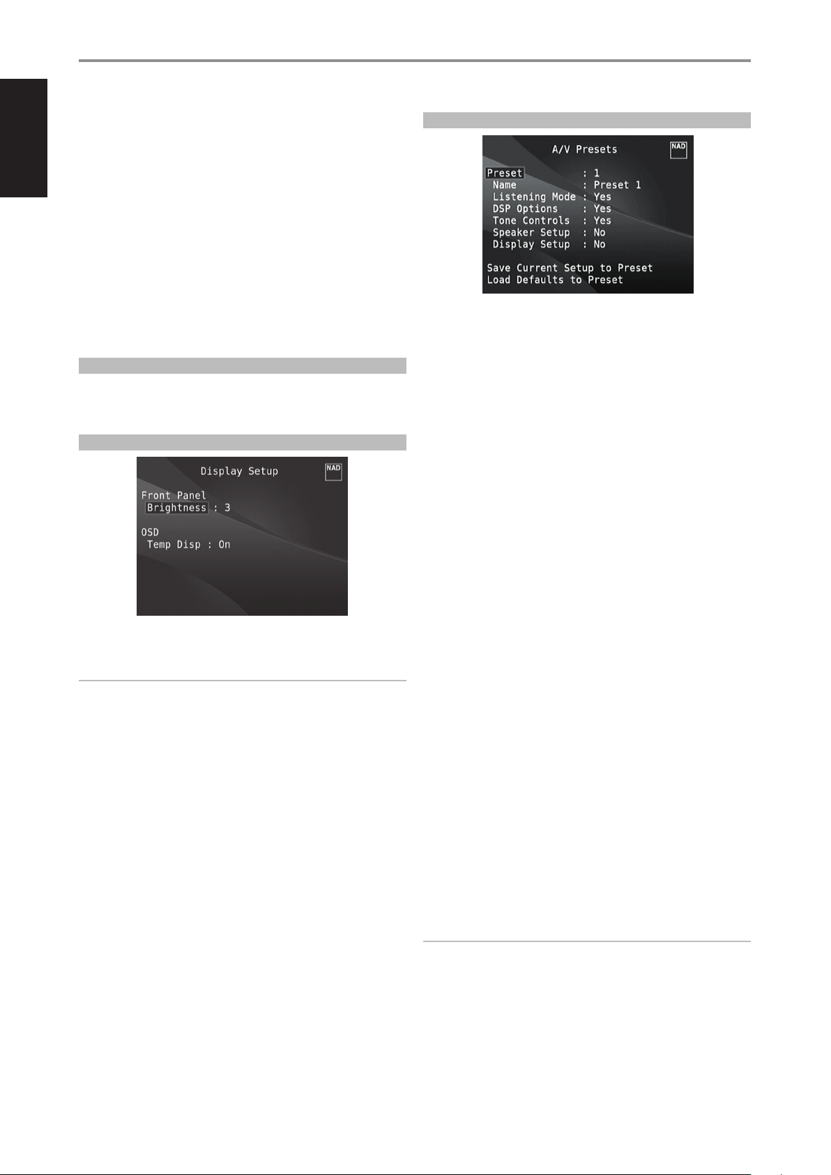
ENGLISH FRANÇAIS ESPAÑOL ITALIANO DEUTSCH NEDERLANDS SVENSKA РУССКИЙ
OPERATION
USING THE M17 SETUP MENU
DTS NEO: 6™ SURROUND
This mode applies the conventional 2-channel signals such as digital PCM
or analog stereo signals to the high precision digital matrix decoder used
for DTS-ES Matrix 6.1 to achieve 6.1-channel surround playback. DTS Neo: 6
surround includes two modes for selecting the optimum decoding of the
signal sources:
DTS NEO: 6 CINEMA: This method is ideal for the reproduction of
movies. The decoding takes place by emphasizing the separation
in order to achieve the same atmosphere with 2-channel, as with
6.1-channel sources.
DTS NEO: 6 MUSIC: Mainly recommended for music reproduction. The
right and left front channels do not pass through the decoder and are
reproduced directly so there is no loss in sound quality, and the eects
of the right surround, left surround, central and back surround channels
add a natural sensation of expansion of the sound eld.
ENHANCED STEREO
Please refer to the same description of “ENHANCED STEREO” under the
“LISTENING MODES” segment of the “OPERATION - USING THE M17 - MAIN
MENU”.
DISPLAY SETUP
A/V PRESETS
The M17’s simple but powerfully exible system of “A/V Presets” allows
you to customize virtually every aspect of your audio-video playback, and
recall them with a single key-press. The parameters “Listening Mode”, “DSP
Options” and “Tone Controls” accessible via the “Main Menu” together with
“Speaker Setup” and “Display Setup” congurable through “Setup Menu” are
stored together as a single A/V Preset.
You might create one A/V Preset optimized for pop music and another for
classical. One more A/V Preset can be set up to recall each family member’s
favorite setting or one for fully cinematic home-theater playback and yet
another one for late-night movies, with each A/V Preset ne-tuned to a
particular scenario or preference.
The “Display Setup” menu allows adjusting the brightness of the Vacuum
Fluorescent Display (VFD) and availability of On-Screen Display (OSD).
NOTE
The congurations set forth at “Display Setup” are carried over whenever
it is enabled during A/V Preset setting. Please see also the section below
about “AV Presets”.
Brightness: Reduce or increase brightness level of the VFD. “1” is the
lowest brightness level and “3” the highest brightness setting.
Temp Disp: This applies to the OSD that is temporarily shown at video out
whenever any of the front panel controls or their corresponding keys in the
remote control is activated. Set to “On” if it is desired to show the applicable
OSD at the monitor/TV; otherwise, select “O”.
CREATING PRESETS
Creating an A/V Preset consists simply of storing a complete set of the
parameters set forth in “Listening Mode”, “DSP Options” and “Tone Controls”
accessible via the “Main Menu” together with “Speaker Setup” and “Display
Setup” congurable through “Setup Menu”.
Scroll to “A/V Presets” using the [R/T] keys to save a collection of said
parameter settings to a Preset. Select a Preset number and by pressing the
[R/T] keys, you can selectively include in the particular A/V Preset any of
the above-mentioned parameter settings by choosing “Yes”. If you decide
not to include in the particular A/V Preset a certain parameter setting, select
“No”.
Now in order to save the settings chosen for the particular A/V Preset
number, scroll down to “Save Current Setup to Preset” and press the [E]
key. If you chose to load instead the default settings, scroll down to “Load
Defaults to Preset” and press the [E] key to restore the default settings.
In addition to the parameter settings, the A/V Preset label itself can be
assigned a new name. This new Name will be shown in the VFD as well as
on the OSD.
To rename the A/V Preset label, scroll to “Name” and press [E] to go the rst
character. Then, press [R/T] to pick and select through the alphanumeric
selections. Press [W/E] to move to the next character or back to the
previous character and at the same time save the changes done on the
current character.
26
NOTE
The selected A/V Preset remains in force until you select a dierent A/V
Preset.
Page 27
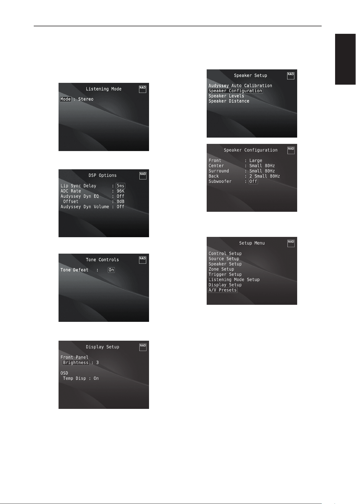
OPERATION
USING THE M17 SETUP MENU
SAMPLE PROCEDURE FOR SETTING UP A/V PRESETS
1 Setup rst your preferred settings for the following options (access
them through their respective menu page).
Listening Mode: Stereo
DSP Options: 5ms
Speaker Setup: from the Speaker Setup menu, go to “Speaker
Conguration” sub-menu and change “Subwoofer” from “On” to “O”:
“Front” becomes “Large”
2 With the above settings, scroll to “A/V Presets” from the SETUP MENU
page. Use [E] to access “A/V Presets” menu.
ENGLISHFRANÇAISESPAÑOLITALIANODEUTSCHNEDERLANDSSVENSKAРУССКИЙ
Tone Controls: Tone Defeat: On
Display Setup: Set “Brightness” to “3”
27
Page 28
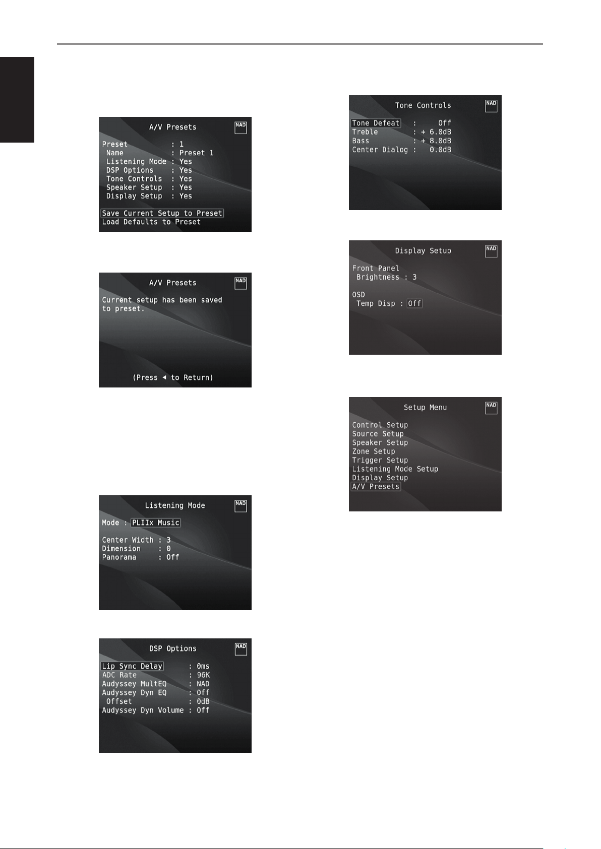
ENGLISH FRANÇAIS ESPAÑOL ITALIANO DEUTSCH NEDERLANDS SVENSKA РУССКИЙ
OPERATION
USING THE M17 SETUP MENU
3 At “A/V Presets” page, set “Preset: 1” to the following conditions - use
[R/T] to select “Yes” or “No” and press [ENTER] to conrm selection and
move on to the next setting.
While at “Save Current Setup to Preset” menu line, use [E] to save the
above settings to Preset 1. Below OSD will be shown, arming that the
above settings are now saved to “Preset 1”.
Tone Controls: Tone Defeat: O
Display Setup: Set “Temp Disp” to “O”
When you recall “Preset 1” using the remote control (for HTRM 2, “A/V
PSET” + “1”), the above preset values allocated at “Preset 1” (preset
settings as shown in the OSD captures at Step 1) will be recalled and
implemented at the current source.
4 Now, repeat again Step 1 above but this time with the following
settings
Listening Mode: PLIIx Music
DSP Options: 0ms
5 With the above settings, scroll to “A/V Presets” from the SETUP MENU
page. Use [E] to access “A/V Presets” menu.
28
Page 29
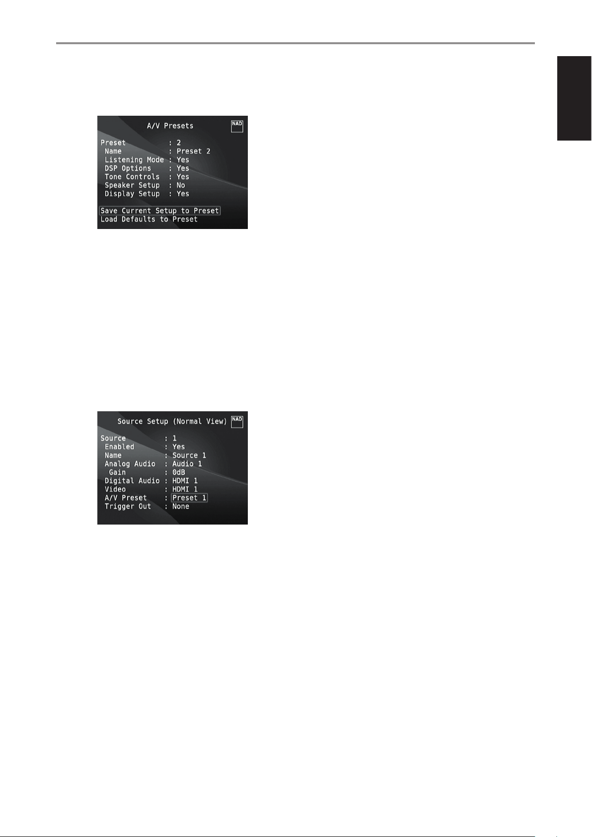
6 At “A/V Presets” page, set “Preset: 2” to the following conditions - use
[R/T] to select “Yes” or “No” and press [ENTER] to conrm selection and
move to the next setting.
While at “Save Current Setup to Preset” menu line, use [E] to save the
settings above to “Preset 2”. When you recall “Preset 2” using the remote
control (for HTRM 2, “A/V PSET” + “2”), the above preset values allocated
at “Preset 2” (preset settings as shown in the OSD captures at Step 4) will
be recalled and implemented at the current source.
Note that “Speaker Setup” is set to “No”. At this condition, there will be
no “Speaker Setup” values that will be implemented at “Preset 2”. The
“Speaker Setup” settings that will be applied at “Preset 2” will be the last
or current “Speaker Setup” settings which in this sample are the same
“Speaker Setup” settings shown above in Step 1.
OPERATION
USING THE M17 SETUP MENU
ENGLISHFRANÇAISESPAÑOLITALIANODEUTSCHNEDERLANDSSVENSKAРУССКИЙ
7 You can setup up to 5 A/V Presets. These same A/V Presets can also
be associated/defaulted to each Source in the “Source Setup (Normal
View)” window as below.
In the above example, “Preset 1” settings are allocated for Source 1.
Whenever Source 1 is accessed, the “Preset 1” settings will be applied
to Source 1. You can still manually override the assigned A/V Preset
allocation in a specic Source with another Preset setting/number by
way of pressing the appropriate remote control buttons.
RECALLING PRESETS
You may recall an A/V Preset number at any time using the HTRM 2 remote
control. Press the HTRM 2’s A/V PSET key and then the numeric key 1-5
corresponding to the desired A/V Preset number. The newly recalled A/V
Preset will then manifest or replace the previous A/V Preset (if any).
29
Page 30
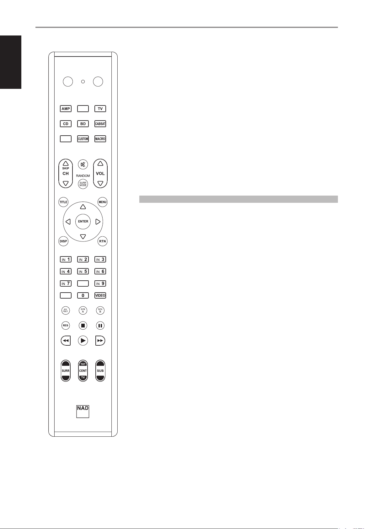
ENGLISH FRANÇAIS ESPAÑOL ITALIANO DEUTSCH NEDERLANDS SVENSKA РУССКИЙ
OPERATION
USING THE HTRM 2 REMOTE CONTROL
The NAD HTRM 2 is ready to operate the M17 right out of the box, but it is really eight remotes in one.
Each of the 8 Device Selector keys at the top of the handset can call up a new “page” of remote control
codes to be transmitted by the remaining keys. You may “teach” codes from any infrared-remote
ON
DEVICE SELECTOR
DAC
OFF
MP
MMUUTTEE
controlled component, regardless of brand, to any or all of these.
Obviously, the most logical system is that you teach the codes from your BD player to the [BD] Device
Selector “page,” your television’s codes to the [TV ] “page,” and so on, but there is no required scheme:
You may load any commands to any key on any page (see “Learning Codes From Other Remotes,”
below).
The HTRM 2 is already preprogrammed with a full complement of commands for the M17 on its
[AMP] Device Selector page, and as well as with library commands to operate most NAD-brand CD,
BD or DAC components on the corresponding Device Selector “pages.” These default commands are
permanent: Even if you teach the HTRM 2 new commands to take their place, the underlying library
commands remain in place and can easily be recalled should you add an NAD component to your
system later (see “Delete Mode”, below).
SOURCE
SSLLEEEEPP
IN
8
SSEETTUUPP DDEELLAAYY // PPIICCTTUURREE TTEESSTT // ZZOOOOMM
IN
10
PPRROOGGRRAAMM CCLLEEAARR RREEPPEEAATT
EEQQ TTOONNEE LL..NNIITTEE
DDIIMMMMEERR
Note: For use with the M17, it should not be necessary to re-program any keys on the HTRM 2 [AMP]
page. However, in order for the HTRM 2 to control your specic NAD-brand components you may
need to load one or more dierent code-libraries (see “Loading Code Libraries,” below).
CONTROLLING THE M17
The HTRM 2 is divided into two main sections. Eight Device Selector keys at the top—[AMP], [MP,]
[TV,] and so on—set the handset’s remaining keys to a “page” of commands to control a particular
component. A Device Select key determines only what component the HTRM 2 will command; it
does not perform any function on the M17. All of the remaining keys are function keys that can “learn”
control codes from virtually any infrared remote controller, allowing you to teach the codes of your
equipment, regardless of brand, to the HTRM 2.
However, the HTRM 2 is already preprogrammed to operate the M17. All of the function keys on the
[AMP] Device Selector “page” perform M17 functions. (The HTRM 2 can also command many other
NAD components, from its [CD], [BD], [DAC] and [CUSTOM] pages.)
It is important to note that certain HTRM 2 keys perform dierent functions depending on the selected
Device Selector “page.”
30
CHANNEL VOLUME
HTRM 2
Page 31

OPERATION
USING THE HTRM 2 REMOTE CONTROL
LEARNING CODES FROM OTHER REMOTES
Begin by positioning the HTRM 2 “nose-to-nose” with the source remote so
the two devices’ infrared windows are about 2 inches apart.
• Enter Learning Mode: On the HTRM 2, simultaneously press-and-hold
for 3 seconds both a Device Selector key and the [RES] key until the
Learn LED (located between HTRM 2’s ON and OFF buttons) turns
steady green.
• Press the HTRM 2’s function key you wish to teach a command; the
Learn LED will turn amber.
• Press-and-hold the function key on the source remote: The HTRM 2’s
Learn LED will icker amber for a second or two, then turn solid green.
The command is learned.
• Press the HTRM 2’s Device Selector key again to exit the learning mode.
If the Learn LED does not icker amber you may need to vary the distance
between the remotes. If the Learn LED turns red rather than green, that
particular command of that source remote command could not be learned.
Example: Learning “BD Pause”
Position the HTRM 2 and your BD player’s remote as described above.
• On the HTRM 2, simultaneously press-and-hold [BD] and [RES]; the Learn
LED turns steady green.
• Press the HTRM 2’s Pause [ j ] key; the Learn LED turns amber.
• Press-and-hold the corresponding Pause key of your BD player’s remote
control; the HTRM 2’s Learn LED ickers amber and then turns solid
green. The command is learned.
• Press [BD] again to exit the learning mode.
NOTES
• The DEVICE SELECTOR keys can themselves be congured to learn a command.
• Press and hold a congured DEVICE SELECTOR for at least 2 seconds to
execute a function assigned to the particular DEVICE SELECTOR key.
• Shor t press of a congured DEVICE SELECTOR will just switch the active
device.
CANCEL OPERATION
You can cancel conguring a key, by pressing the active Device Selector key
before the learn process is complete; the Learn LED will turn red.
PUNCH THROUGH
The HTRM 2’s “punch-through” function allows you to retain a function key
from one Device Select “page” to another, so that, for example, the AMP
[SURR MODE] function might still control the M17 when the BD Device
Selector page is active.
NOTE
The HTRM 2’s [VOL R/T] keys are pre-programmed as “punched-
through” for all Device Selector pages: [VOL R/T] will operate the
M17’s master-volume regardless of the currently selected device. The
[SURR] [CENT] and [SUB] Channel Volume controls similarly are preprogrammed as punched-through.
To set a punch through, after entering the Learning Mode, and pressing the
desired key to be punched through, simply press the device key twice of
the device to punch through to. The status LED will turn green; press the
Device Selector key again to exit Learning Mode.
COPY A COMMAND FROM ANOTHER KEY
You may copy a command from any HTRM 2 key to any other. To copy a key
function, after entering the Learning Mode, and pressing the desired key
to be copied to, simply press the device key from which you wish to copy,
having rst pressed its Device Selector key if it resides on another “page.”
The status LED will turn green; press the Device Selector key again to exit
Learning Mode.
Example: Copy the Pause command from the CD page to the AMP [ j ]
button:
• On the HTRM 2, simultaneously press-and-hold [AMP] and [RES]; the
Learn LED turns steady green.
• Press Pause [ j ] ; the Learn LED turns amber.
• Press [CD]; press Pause [ j ] ; the Learn LED turns green.
• Press [AMP] again to exit the learning mode.
NOTE
The copy and punch-through functions are similar. However, if you
copy a command and then subsequently delete, or over-write the
original (source-key) command , the copied-to key’s command remains
unchanged. If you punch-through to a command and then delete or
over-write the original key, the punched-through functions also change
accordingly.
MACRO COMMANDS
A “macro” command is a series of two or more remote codes issued
automatically from a single keypress. You might use a macro to automate a
simple command sequence, such as, “ Turn on the BD player and then press
PLAY”. Or you might compose an elaborate macro to power up an entire
system, select a source, choose a Listening Mode, and begin playback—
again, all from a single keypress. Each DEVICE SELECTOR and function keys
of the HTRM 2 can be stored one macro.
NOTE
Macros are independent of the currently selected device.
RECORDING MACROS
To record a macro, simultaneously press-and-hold for 3 seconds both the
[MACRO] key and the HTRM 2 function key to which you wish to assign the
macro, until the status LED turns green. The macro button will also light up.
Press the sequence of function keys to be recorded into the macro, being
sure to rst press the requisite Device Selector key for each function (you
may switch devices while recording the macro as many times as necessary),
allowing you to create macro containing commands from more than one
Device Selector “page.”
When you have nished entering the desired command sequence, press
[MACRO] again to store the macro; the Learn LED and [MACRO] key
illumination will turn o.
NOTE
Each macro can store a maximum of 64 command steps. If you exceed
this number, the macro will be stored automatically after the 64th
command is added.
ENGLISHFRANÇAISESPAÑOLITALIANODEUTSCHNEDERLANDSSVENSKAРУССКИЙ
Example: Punch-through AMP [SURR MODE] key to the BD “page”
• On the HTRM 2, simultaneously press-and-hold [BD] and [RES]; the Learn
LED turns steady green.
• Press [SURR MODE]; the Learn LED turns amber.
• Press [AMP] twice; the Learn LED turns green.
• Press [BD] again to exit the learning mode.
31
Page 32
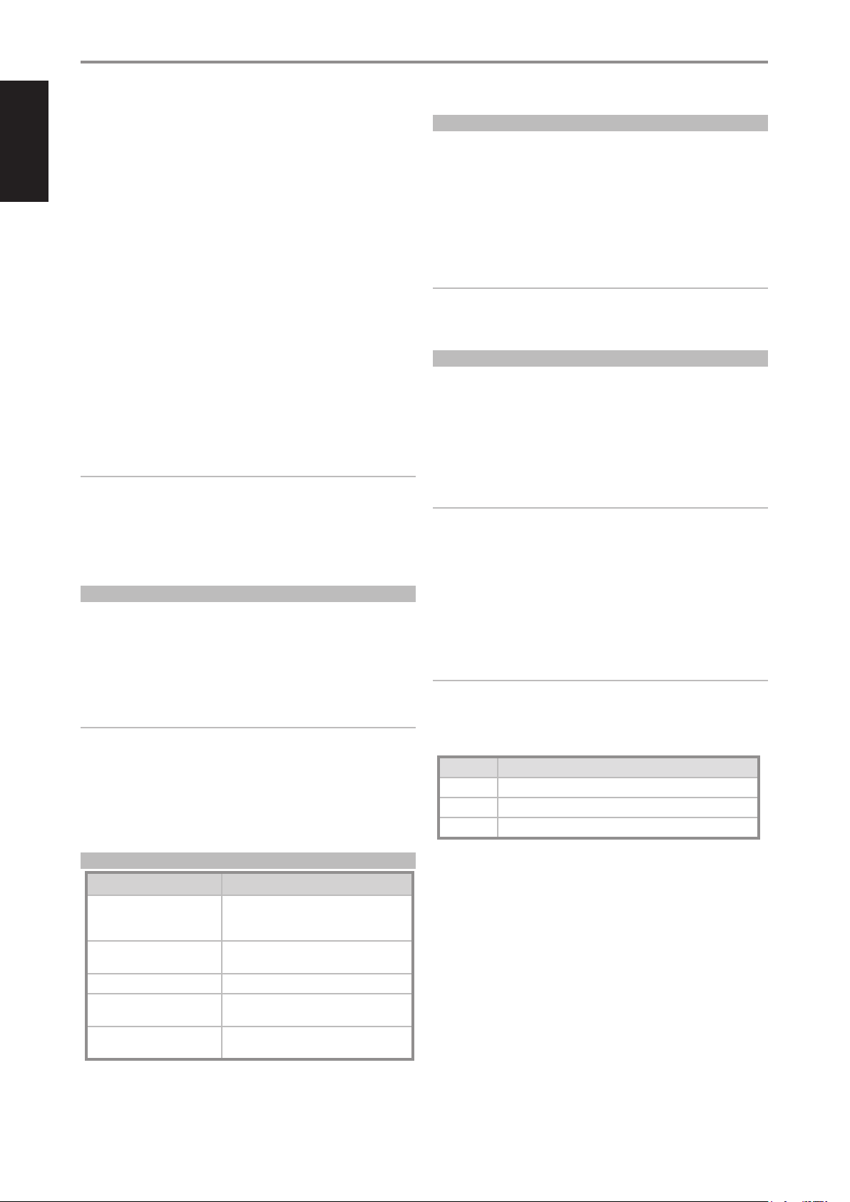
ENGLISH FRANÇAIS ESPAÑOL ITALIANO DEUTSCH NEDERLANDS SVENSKA РУССКИЙ
OPERATION
USING THE HTRM 2 REMOTE CONTROL
Example: Record a Macro to the [0] key to Turn on the M17, Select “Input1”
(Source 1), and Commence Playback of connected Source 1 device (as in
BD player):
• On the HTRM 2, simultaneously press-and-hold [MACRO] and
[0](numeric zero); the Learn LED turns steady green.
• Press [AMP]; press [ON]; press [1] (“Input or Source 1”); press [BD];
press[4] (Play) - the Learn LED blinks as each step is added.
• Press [MACRO] again to exit the macro-record mode.
To clear a macro, perform the above steps without entering any functions.
EXECUTING MACROS
To execute a macro, press and release [MACRO]; its key illumination lights
for 5 seconds. While it remains lit, press an HTRM 2 key to which a macro
has previously been stored.
The corresponding macro will run; as each step executes, its “parent” Device
Selector’s key ashes lights briey; when execution is nished, the [MACRO]
key illumination goes out. Pressing any other HTRM 2 key while a macro is
executing will abort the macro. Remember that you must hold the HTRM 2
so that its infrared emitter can activate the target components.
NOTE
When a macro executes, a 1 second delay is automatically inserted
between its commands. If you need more than a 1 second delay between
particular commands—for example, to permit a component to power
up completely—you can record “empty” steps into the macro by
changing Device Selector “pages” without entering actual command
functions.
KEY ILLUMINATION TIMEOUT
The HTRM 2’s key-illumination can be set to remain lit for 0-9 seconds. The
default value is 2 seconds. To set the illumination timeout, simultaneously
press-and-hold for 3 seconds both the HTRM 2’s [DISP] and the [0-9] key,
with the digit corresponding to the desired timeout duration; the Learn
LED will ash twice to conrm the new setting. When set to zero, the
illumination will not turn on at all.
NOTES
• Key illumination is activated when one presses any HTRM 2 key.
• If HTRM 2 senses movement, key illumination is activated without
having to press a key. If HTRM 2 is shaken, key illumination is also
activated.
• Key illumination is the biggest drain on the HTRM 2’s batteries. A short
key illumination timeout will extend battery life appreciably; turning it
o altogether (set it to 0 seconds) will lengthen it still further.
FACTORY RESET
The HTRM 2 can be reset to its factory state, deleting all learned commands,
copied and punched-through keys, macros, and other setup information,
reverting all keys to their pre-programmed library commands.
To perform a factory reset simultaneously press-and-hold for 10 seconds
the HTRM 2’s [ON] and [RTN] keys; the Learn LED will start to ash green.
Release [ON] and [RTN] before the second ash is complete; the Learn LED
will turn red, indicating the remote has been reset.
NOTE
You must release [ON] and [RTN] before the second ash goes out,
otherwise the unit will not reset; should this occur, repeat the full
procedure.
DELETE MODE
The HTRM 2 can store learned, copied, and “default library” commands on
any single key (The default library commands are the pre-programmed
NAD codes, such as the native M17 commands on the [AMP] “page.”).
You can delete commands by layers back “down” to the default library
command on any key, removing learned commands, punched-through
functions, and copied keys.
NOTE
The default library commands cannot be deleted, so you need not worry
that using Delete Mode might cause irreparable changes.
To enter Delete Mode, simultaneously press-and-hold for 3 seconds both
the desired key’s Device Selector key and the [RTN] key, until the Learn LED
turns green. Press the function key whose command you wish to delete;
the Learn LED ashes; the number of times indicates which type of function
has become active - see the table below. Press the active Device Selector
key again to exit Delete Mode.
NOTE
You may delete multiple function-key commands on the same Device
Selector “page,” but to delete from more than one Device Selector page
you must exit Delete Mode and then re-enter it on the required page.
Flashes Command Type
1 Default Librar y Command
2 Copied Library Command
3 Learned Command
CONFIGURING KEY ILLUMINATION
Keys to Press (for 3 seconds) Mode
DISP + Digit Key (0-9) Set key illumination timeout to number of
DISP + OFF Disable light sensor. Key illumination will turn
DISP + ON Enable light sensor.
DISP + ENTER Set the light sensor threshold to the current
DISP + RTN Restore all key illumination settings to the
seconds corresponding to digit key. Zero turns o
the key illumination entirely.
on with any key press.
light level.
defaults.
32
Page 33
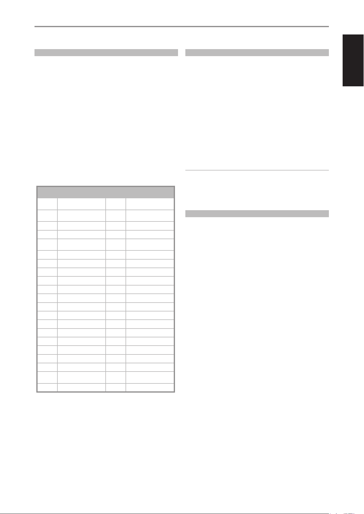
OPERATION
USING THE HTRM 2 REMOTE CONTROL
LOADING CODE-LIBRARIES
The HTRM 2 can store a dierent library of default NAD codes for each of
its Device Selector “pages.” If the original default library does not control
your NAD CD player, tape deck, BD player, or other component, follow the
procedure below to change the code-library.
Begin by ensuring that the component you wish the HTRM 2 to control
is plugged in and powered-up (“on,” not merely in standby). To enter the
HTRM 2s Library Mode, simultaneously press-and-hold for 3 seconds both
the desired Device Selector key and the [A/V PSET] key, until the Learn LED
turns green.
While keeping the HTRM 2 pointed toward the component, enter the rst
appropriate three-digit code-library number from the table below. Press
[OFF]. If the component turns o, press [ENTER] to accept that code-library
number and exit the Library Mode. If the component does not turn o,
enter the next three-digit code-library number from the table.
When you enter the correct number the component will turn o; press
[ENTER] to accept that code library number and exit the Library Mode.
LIBRARY
CODE
100
101
102 S170 302 L70 Tuner
103 L75 303 L53 Tuner
104
3112 Zone 3 305 C425
4112 Zone 4 306 C445
105 L70 307 Txx5 Series Tuner
106 L76 400 Tape Deck B
107 118 401 TAPE Deck A
108 L53 500 TV 280
109 L73 501 MR13
110 Stereo Receiver / Amplier 502 MR20
111 Stereo Second Zone 503 PMR45
112 Txx5 Series 600 T535, T562, T585, M55
200 CD Player 601 T550, L55
201 CD Player (old) 602 T512, T531, T532, T571, T572
202 5170, 5240, 5340 603 L70, L73 BD
203 5325 604 L56
204 5060 605
205 M5 606 L53 BD
NAD PRODUCT
DESCRIPTION
Receiver/Processor (Discrete
ON/OFF)
Receiver/Processor (Toggle
ON/OFF)
Second Zone Commands
(Zone 2)
LIBRARY
CODE
300 Tuner
301 L75, L76 Tuner
304 L73 Tuner
NAD PRODUCT
DESCRIPTION
T513, T514, T515, T517,
T524, T533, T534
SEARCH MODE
If none of the codes from the table, when entered, turns on the
component, and if you are quite sure you have followed the above
procedure completely and carefully, you may want to try the “search”
method as follows:
Enter Library Mode by simultaneously pressing-and-holding for 3 seconds
both the desired Device Selector key and the [A/V PSET] key, until the Learn
LED turns green. Now press-and-hold the HTRM 2’s [R] or [T]) key; the
remote will step through all the available codes at a rate of approximately
1 per second.
When the component turns o, immediately release the cursor key; press
[ENTER] to accept that code-library and exit the Library Mode. Try a few
commands; should you prove to have stepped past the needed codelibrary, re-enter the Library Mode and use the cursor key to step back to it.
NOTE
It is possible that search mode will nd code-libraries that operate, at
least partially, some other brand (non-NAD) components. You may
certainly exploit such capabilities as you nd them. However, since we
can only ensure the completeness or accuracy of NAD code-libraries, we
cannot support the HTRM 2’s operation with other-brand components.
CHECKING CODE-LIBRARY NUMBER
You can check the current code-library on any Device Selector key as
follows. Enter Library Mode by simultaneously pressing-and-holding for
3 seconds both the desired component’s Device Selector key and the
[A/VPSET] key, until the Learn LED turns green. Press the [DISP] key; the
HTRM 2 indicates the current code-library by ashing its [DAC], [CUSTOM],
and [MACRO] keys.
For example, to indicate code-library #501, the HTRM 2 will ash [DAC] 5
times, pause, and then ash [MACRO] once. You might wish to make a note
of your components’ code-library numbers.
ENGLISHFRANÇAISESPAÑOLITALIANODEUTSCHNEDERLANDSSVENSKAРУССКИЙ
33
Page 34
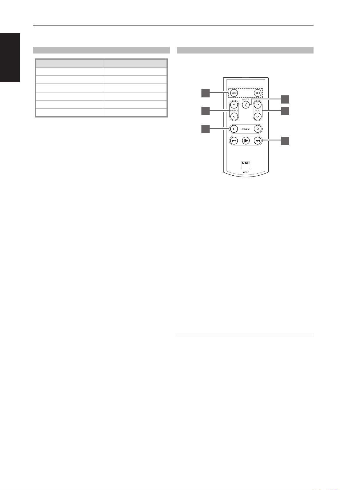
ENGLISH FRANÇAIS ESPAÑOL ITALIANO DEUTSCH NEDERLANDS SVENSKA РУССКИЙ
OPERATION
USING THE HTRM 2 REMOTE CONTROL
SUMMARY OF THE HTRM 2 MODES
Mode Keys To Press (for 3 seconds)
Learn/Copy/Punch Through Device Key + RES Key
Delete Mode Device Key + RTN Key
Macro Record Macro Key + Function Key
Library Mode Device Key + [A/V PSET] Key
Back Light Timeout DISP Key + Digit Key
Factory Reset See “Factory Reset” above
USING THE ZR 7 REMOTE CONTROL
The ZR 7 is a discrete compact remote for controlling the Zone 2 feature of the
M17. Irrespective of the main room/zone settings, the ZR 7 allows full separate
control of the Zone 2 source selection among other applicable features.
1
3
2
4
SLEEP MODE
The Sleep Mode timer will switch the M17 to Standby mode automatically
after a preset number of minutes. Pressing the HTRM 2’s SLEEP button once
will display the setting of the sleep time increment. Pressing the HTRM 2’s
SLEEP button a second time within a 3-second period will change the
sleep time increment in 15-minute intervals, after which time the M17 will
automatically switch into Standby mode.
To adjust the sleep delay, press the HTRM 2’s SLEEP button twice; rst
to display the sleep time increment, and a second time to change the
sleep time increment. The sleep time increment and a “SLEEP” icon will
continuously display on the M17’s front panel Vacuum Fluorescent Display
(VFD). Each consecutive press increases the sleep time in 15-minute
increments from 15 to 90 minutes. To cancel the sleep mode, continue
pressing the HTRM 2’s SLEEP button until “Sleep O” displays on the VFD.
Switching the M17 to standby from either the HTRM 2’s OFF or the M17’s
STANDBY button will also cancel the sleep mode
5
6
1 ON/OFF: Switch ON/OFF Zone 2.
2 SOURCE [ d/f ]: Select the active input of the NAD M17 that will be
sent out to the corresponding rear panel ZONE 2 output port.
3 MUTE: Temporarily switch OFF or restore the Zone Volume level.
4 VOLUME [ d/f ]: Increase or decrease the loudness level of selected
Zone source. This is possible only if the VOLUME setting of ZONE 2
CONTROLS is set to VARIABLE.
5 PRESET [ a/s ]: Step up or down between stored radio presets. This
control button is possible if the selected Zone is “ TUNER” and the active
tuner section has stored presets. This control button is not applicable to
M17.
6 The following CD Player Zone buttons can control a compatible CD
Player. The CD Player has to be powered ON and disc loaded.
SKIP [ 9 ]: Go to the beginning of a track/le or previous track/le.
SKIP [ 0 ]: Go to the next track/le.
[ 4 ]: Start playback.
34
NOTE
The ZR 7 remote control will only control Zone 2 applications. Zone3
and Zone 4 could be congured and managed at the appropriate
Zone OSD menu using the front panel navigations keys as well as
the corresponding keys on the HTRM 2 remote control. The HTRM 2’s
‘CUSTOM’ device is also defaulted to Zone 2 remote control codes.
Page 35
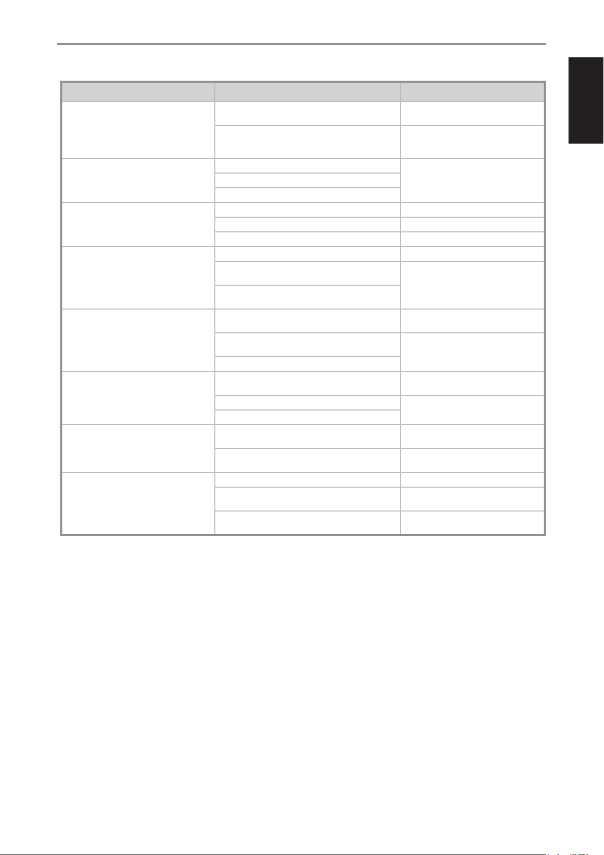
REFERENCE
TROUBLESHOOTING
CONDITION POSSIBLE CAUSES POSSIBLE SOLUTIONS
Cannot power up M17, always at standby
mode.
No sound from all channels. • AC power unplugged. • Check AC cable connection and outlet.
No sound from some channels. • Faulty/missing cables. • Check cables.
No sound from surround channels. • No surround listening mode is engaged. • Select appropriate listening mode.
No sound from Subwoofer. • Subwoofer is o, not powered or improperly
No sound from Center channel. • Source is a 2/0 (etc.). Dolby Digital or DTS recording
No Dolby Digital/DTS. • Source’s digital output is not connected to a M17
M17 does not respond to HTRM 2 remote
control commands.
• +12V TRIGGER IN (OFF/AUTO) switch is set to AUTO. • Set +12V TRIGGER IN (OFF/AUTO) switch
• With +12V TRIGGER IN (OFF/AUTO) switch set to
AUTO, “Auto Trigger In” at “Trigger Setup” menu is set
to “Main” or “All”.
• Power not switched on.
• Outlet has no power.
• “Speaker Conguration” channel (s) set to “OFF”. • Check “Speaker Conguration” menu.
• Power-amp connections faulty. • Check power amplier and cabling.
• Surround-channels set to “OFF” on “Speaker
Conguration” menu.
• Surround-channels level set too low on “Speaker
Levels” menu.
connected.
• Subwoofer set to “OFF” on “Speaker Conguration”
menu.
• Sub level set too low on “Speaker Levels” menu.
without center channel.
• Center set to “OFF” on “Speaker Conguration” menu. • Correct “Speaker Conguration” or
• Center level set too low on “Speaker Levels” menu.
digital input.
• Source component not congured for multichannel
digital output.
• Batteries are at or incorrectly inserted. • Check batteries.
• IR transmitter window on remote or IR A/V Receiver
window on M17 is obstructed.
• M17 front panel is in very bright sunlight or ambient
light.
to OFF.
• Set “Auto Trigger In” to Zone 2, Zone 3
or Zone 4.
• Correct “Speaker Conguration” or
“Speaker Levels” settings.
• Power-up subwoofer, check Sub’s AC
outlet or check connections.
• Correct “Speaker Conguration” or
“Speaker Levels” settings.
• Play a known 5.1-channel recording or
select Dolby Pro Logic IIx Music mode.
“Speaker Levels” settings.
• Check connections.
• Check source component setup.
• Check IR windows and ensure clear lineof-sight from remote to M17.
• Reduce sunlight/room lighting.
ENGLISHFRANÇAISESPAÑOLITALIANODEUTSCHNEDERLANDSSVENSKAРУССКИЙ
35
Page 36

ENGLISH FRANÇAIS ESPAÑOL ITALIANO DEUTSCH NEDERLANDS SVENSKA РУССКИЙ
REFERENCE
SPECIFICATIONS
OVERALL SPECIFICATIONS
Line Level Input
Input impedance (R and C) 56 kΩ + 220 pF
Input sensitivity 40 mV (ref. 500 mV out)
Maximum input signal >8 Vrms
Signal/Noise ratio, A-weighted >90 dB (ref. 500 mV in 500 mV out, volume set to unity gain)
>80 dB (ref. 2 V out, Volume maximum)
Channel Separation >70 dB (ref. 1 kHz/10 kHz)
Frequency response ±0.3 dB (ref. 20 Hz - 20 kHz, Tone Active)
±0.3 dB (ref. 20 Hz - 20 kHz, Tone Defeat)
Frequency response (subwoofer out) 10 - 200H z (ref. -3 dB)
Output
Maximum output level >8 Vrms into 600 Ω
THD (CCIF IMD, DIM 100) <0.005% (ref. 20 Hz - 20 kHz, 2 V out)
XLR >2 Vrms
Standby mode <0.5 W
Tone Controls
Treble ±10 dB at 10 kHz (ref. 2V in 2V out)
Bass ±10 dB at 100 Hz (ref. 2V in 2V out)
Connections
HDMI Up to 1080p
Optical 3 Vpp
Coaxial 0.5 Vpp
Ethernet RJ45 10/100 Ethernet Tx
DIMENSION AND WEIGHT
Unit dimensions (W x H x D) * 435 x 156 x 386 mm
17 / x 6 / x 15 / inches
Shipping weight 17.5 kg (38.6 lbs)
* - Gross dimension includes feet, volume knob and extended rear panel terminals.
Specifications are subject to change without notice. For updated documentation and features, please check out www.NADelectronics.com for the latest information about M17.
Manufactured under license under U.S. Patent #’s: 5,451,942; 5,956,674; 5,974,380;5,978,762; 6,226,616; 6,487,535; 7,212,872; 7,333,929; 7,392,195; 7,272,567 & other U.S. and worldwide patents issued & pending. DTS is a
registered trademark and the DTS logos, Symbol, DTS-HD and DTS-HD Master Audio are trademarks of DTS, Inc. © 1996-2008 DTS, Inc. All Rights Reserved.
Manufactured under license from Dolby Laboratories.
“Dolby”, “Pro Logic”, and the double-D symbol are registered trademarks of Dolby Laboratories.
HDMI, the HDMI logo and High-Definition Multimedia Interface are trademarks or registered trademarks of HDMI Licensing LLC.
Manufactured under license from Audyssey Laboratories. U.S. and foreign patents pending. Audyssey MultEQ XT is a trade-mark of Audyssey Laboratories.
This product incorporates copyright protection technology that is protected by method claims of certain U.S. patents and other intellectual property rights owned by Macrovision Corporation and other rights owners.
Use of this copyright protection technology must be authorized by Macrovision Corporation, and is intended for home and other limited viewing uses only unless otherwise authorized by Macrovision Corporation.
Reverse engineering or disassembly is prohibited.
36
Page 37

ENGLISHFRANÇAISESPAÑOLITALIANODEUTSCHNEDERLANDSSVENSKAРУССКИЙ
37
Page 38

www.NADelectronics.com
©2015 NAD ELECTRONICS INTERNATIONAL
A DIVISION OF LENBROOK INDUSTRIES LIMITED
All rights reserved. NAD and the NAD logo are trademarks of NAD Electronics International, a division of Lenbrook Industries Limited.
No part of this publication may be reproduced, stored or transmitted in any form without the written permission of NAD Electronics International.
While every effort has been made to ensure the contents are accurate at the time of publication, features and specifications may be subject to change without prior notice.
M17_ENG_OM_V10 JAN 2015
 Loading...