

NAD 3140 Owners manual
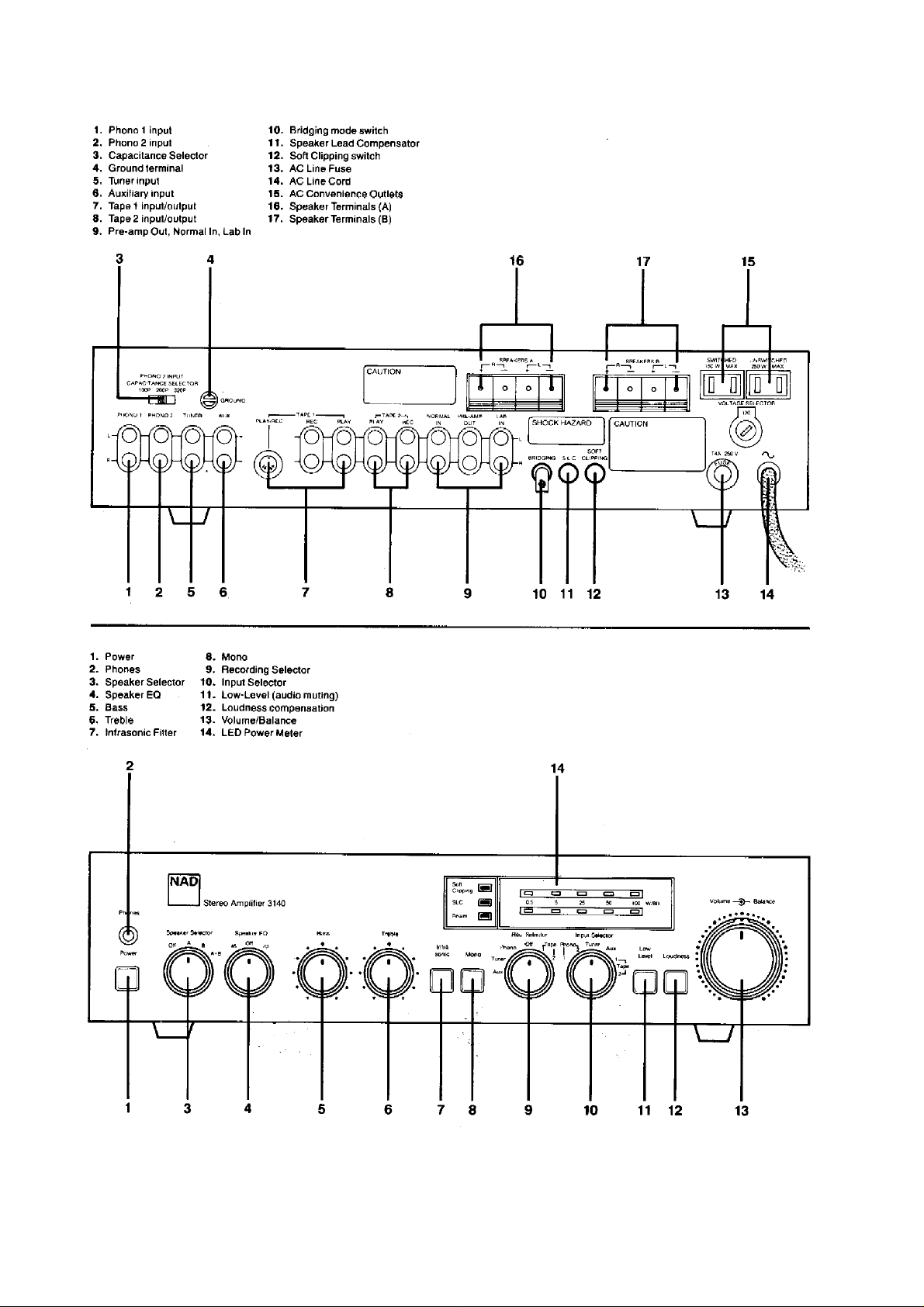

REAR PANEL CONNECTIONS
1. PHON011NPUT.
moving-coil cartridges such as the NAD 9000, Dynavector
and 10X, Satin M18 and M117, Adcom XC/LT, et al.
This input may also be used with cartridges of other types which
have lower-than-normal output voltage, such as the B&O
and Audio-Technica models AT-22 through AT-25. The
has a standard input i m pédance (47K ohms résistance, 100 pF
capacitance) but is 10 dB more sensitive than the
Moving-coil pickups with low output voltage should be used with
an external transformer or pre-preamp. The output from the step-up
device may then be connected to either Phono 1 or Phono
2. CAUTION: Some step-up devices may produce a high enough
output level to overload the Phono 1 input, yielding distortion; in
of doubt, use Phono 2. Here’s one way t o t el l: if yo u f ind that
amplifier is driven to full power (as indicated by the peak-reading
front-panel LED display) with a volume-control setting of 12 o'clock or
lower, then you should switch to the less sensitive Phono 2 input.
Conversely, if you must turn the volume control up beyond the 3 o'clock
position in order to drive the amp to full peak power, then the extra gain
of the Phono 1 input will be beneficial.
2. PHONO 2 INPUT.
phono cartridges of the moving magnet, induced magnet, moving flux,
and moving iron (variable reluctance) types.
Plug the signal cables from your turntable into these jacks. If the
cables or plugs are color-coded, refer to your turntable's in
manual to learn which cable or plug is for the Left channel and which for
the Right. Be careful to insert each plug fully into the
plug's metal skirt fits tightly over the exte rior of the socke t. If necessary,
carefully crimp the plug's metal skirt
with the socket.
3. CAPACITANCE SELECTOR.
capacitance for PHONO 2 on/y. It enables you to optimise the load
capacitance for those cartridges whose frequency response is affe cted
by this parameter.
If you are using a low-inductance pickup (such as a Grado or
Micro-Acoustics), or a moving-coil cartridge with a transformer or
pre-preamp, then the setting of the Capacitance Selector is
unimportant. But with many high-inductance magnetic pickups, the
capacitance setting will audibly alter the sound of the pickup.
In order to select the best value of preamp input capacitance you
must first determine the total capacitance recommended for the
cartridge. This will usually be included in the maker's specificat
and may also be mentioned in magazine reviews of the
subtract the capacitance of your turntable's tonecables. (Check the specifications supplied with the tonearm, or write to
the manufacturer of the tonearm, or as a last resort assume a typical
value of 150 pF.) After this subt raction, what remains is the desired
value of preamp input capacitance. Set the Capacitance Selector to the
nearest value. It is not necessary to match the computed value exactly :
with most phono cartridges a variation of 50 pF one way or the other will
produce only a very slight change in frequency response.
Example: suppose you are using a Stanton 881S pickup car
in a Pioneer turntable. Stanton specifies a recommended load
capacitance of 275 pF for the cartridge, and the Pioneer turn
cable capacitance of about 100 pF. 275 minus 100 equals 175 pF, so
you should set’ the Capacitance Selector to the
It you prefer, you may simply set the Capacitance Selector by ear
while listening to recordings which are strong in high-frequency
overtones. Typically, when the capacitance is too low the
upper-midrange (the soprano voice range) will be softened and the response at the highest frequencies will be peaky, leading to edgy
This input is designed for use with "high-output"
Phono 1 input
Phono 2 input.
This input is intended for the majority of
socket so that the
slightly so as to obtain a tight fit
This switch selects the input
cartridge. Next,
arm wiring and signal
nearest value, 200 pF.
(Ultimo) 10A
MMC series
case
the
struction
ions,
tridge
table has a
violin tone and increased surface noise. Too high a value of capacitance will bring the upper-midrange forward while rolling off the
extreme highs.
4. GROUND.
(usually a green wire terminating in a U-shaped spade lug),
to this terminal. Turn the thumb-nut counter-clockwise,
lug under the nut, and tighten the thumb-nut clock-wise to secure the
lug. If the grounding wire has no terminal lug, strip off a half-inch (1 to 2
cm) of insulation to expose the bare wire, twist the wire strands tightly
together, insert the wire through the small hole in the shaft of the
Ground terminal, and tighten the
5. TUNER.
jacks. As with ail of the other input/output jacks, the upper
pair is for the left channel and the lower jack is for the
6. AUX. These auxiliary input jacks are for any "line level"
source—such as a spare tape player, a television sound tuner, the
audio line output from a videocassette or videodisc
record player containing a high-output ceramic pickup cartridge.
7. TAPE 1 REC/PLAY.
use with a stereo tape recorder: separate pairs of RECORD and PLAY
phono jacks, and a five-pin DIN socket. If your recorder has only
DIN-type plugs, use the DIN connecter. If your recorder has both a DIN
plug and pairs of phono jacks, it is preferable to use the phono plug
connections. (Do not use both the phono plugs and the DIN plug
simultaneously.)
The TAPE 1 connections may be used with tape recorders of ail
types: cassette, micro-cassette, open-reel, eight-track, digital, etc.
To make recordings, connect a stereo patch cord from the RECord
jacks to the LINE or RADIO input jacks on the recorder (not to ils
microphone inputs). To play back tapes, connect a stereo patch cord
from the recorder's LINE output jacks to the amplifier's PLAY
jacks.
8. TAPE 2 REC/PLAY.
tape recorder of any type, and the amplifier is wired to permit copying
tapes from one recorder to the other. Connect a cable from the RECord
jacks to the tape deck's LINE or RADIO input jacks, and another cable
from the amplifier's P LA Y ja ck s to the recorder's LINE outputs. The
upper jack is for the left channel and the lower jack for the right channel.
The TAPE 2 jacks may be used for a signal-processing accessory
instead of a second tape machine. Examples of such accessories
include a dynamic range processor, a dynamic noise filter, an impulse
noise ("tick and pop") suppressor, and any other processor whose
operation depends on the setting of a signal threshold. Connect a patch
cord from the REC jacks to the processor's inputs, and another patch
cord from the PLAY jacks to the
Other signal processors, such as a graphic equalizer or
equalizer supplied for use with some loudspea ke rs (e.g . Bo se ,
Electro-Voice, KLM), may be connected either to the tape jacks or at
the output of the preamp. The choice is a matter
9. PRE-AMP OUT, NORMAL IN, LAB IN. Each channel of
amplifier is comprised of two independent sections or stages: the
control preamplifier (including the phono preamp and most front-panel
controls), and the power amplifier (which provides the power to drive
loudspeakers). In normal operation the preamp and power amp are
connected together via U-shaped metal jumpers; check to be sure that
they are fully inserted into the jacks and that nothing is touching them.
Two sets of power amp inputs are provided. The LAB inputs
wideband frequency response extending uniformly from low in f raso nic
to high ultrasonic frequencies, and may be used for laboratory tests
and special app l ic a tions. The NORMAL inp uts are equipped with
infrasonic and ultrasonic filters; these reject any
If your turntable is equipped with a grounding wire
thumb-nut to fasten the wire in place.
Connect the signal cable from a radio tuner to these
connect it
place the spade
one in each
right channel.
signal
player, or a child's
Two types of connectors are provided
input
These jacks enable connection of a
processor's outputs.
of convenience.
second
the special
have
for
the

interference which occurs outside of the audible frequency range, in
order to prevent intermodulation distortion and preserve the
amplifier's power for music.
For conventional operation the PRE-AMP OUTjacks are
connected to the NORMAL IN jacks by means of the metal jumpers.
Removal of the jumpers (with the POWER switched OFF)
various signal-processing accessories to be connected in
path between preamp and power amp: an equalizer, a
ambience reproducer, a stereo image enhancer, etc. To
processor, connec t a stereo pa tch cord fro m the PRE
the processor's line-level input jacks, and a
processor's output jacks to the
any signal processor whose
threshold, such as a dynamic noise filter or a DBX decoder, should be
connected to one of the
signal levels are unaffected by volume and tone controls—rather than to
the PRE-AMP
If you remove the metal jumpers, save them in case you may
to disconnect the signal processor and return to normal operation at a
later time. If the jumpers should be lost, a conventional
cord can be used to connect PRE-AMP OUT to NOR
The NAD 3140 can be used as the heart of an elaborate audiophile
sound System. For example the PRE-AMP OUT jacks
connected via a stereo patch cord to any high-quality
amplifier. To use a separate high-power amplifier
loudspeakers while continuing to use the NAD 3140's
amp for headphones or another set of loudspeakers, simply install
Y-connector adapters to split the signal from the PRE-AMP OUTjacks.
The preamp stage is capable of driving
parallel, or driving the long signal cables required to connect to power
amps which are located near the
loudspeakers with built-in power amps. The preamp output can also be
fed to a time-delay ambience sys-tem, with the 3140's built-in power
amp used to drive either the main stereo speakers or the time-delayed
ambience speakers. In a bi-amplified System the preamp output is fed
to the input of an electronic crossover; the low-frequency output of the
crossover unit is fed to the amplifier which drives the woofers, while the
high-frequency output of the crossover unit is fed to the 3140's
NORMAL IN or LAB IN jacks, and the speakers' tweeters are
connected directly to the 3140's SPEAKER terminals.
10. BRIDGING MODE SWITCH.
3140's two power amplifier channels to form a monophonic amplifier
with more than double the output power. To convert to
operation, the following procedure should be followed.
(1) Disconnect the metal jumper or signal cable from the
left-channel input to the power amplifier section of the 3140. In the
bridged (monophonic) mode the amplifier is driven through its
right-channel input only (either the NORMAL or LAB input socket).
you need stereophony reproduction, the left-channel PRE-AMP OUT
signal can be used to drive a second, separate power ampli
loudspeaker, (If another 3140 in bridged mode is used for the second
channel, it too will be driven through its right channel
regardless of whether it is used for the right or left speaker.)
(2) Disconnect any speaker wires from both the SPEAKERS A and
SPEAKERS B terminals. From the speaker which is to be driven by the
3140, connect its positive lead to the red R+ terminal, and its negative
lead to the red L+ terminal, in the SPEAKERS A
NOTE; do not connect any wires to the black
If you wan t to d r ive t wo s p ea k er s in p a r a ll e l, co n ne ct t he s e cond
speaker's leads to the red (R+ and L+) terminals in the
group; make no connection to the black (R- and
the bridged monophonic mode, the loudspeaker's impedance appears
to be halved as "seen" by the amplifier. An 8-ohm load looks like 4
ohms, a 4-ohm load looks like
OUTjacks.)
enables
the signal
time-delay
use a signal
amplifier's NORMAL IN jacks. (Note:
second patch cord from the
operation depends on the setting of a
sets of TAPE REC/PLAY jacks—where the
several power amplifiers in
speakers, or to "powered"
AMP OUT jacks to
stereo patch
MAL IN or LAB IN.
may be
separate power
for one set of
built-in power
This switch "bridges" the
bridged
NAD
fier and
power amp input
group of terminals.
(R- and L-) terminals.
SPEAKERS B
L-) terminals. NOTE: in
want
If
2 ohms, and a pair of 4-ohm speakers operated in parallel will look
Iikea1-ohm load. Driving a pair of such speakers to high levels
cause the amplifier to overheat, activating its
CAUTION:
"floating" with respect to ground. Do NOT connect the speake r
anything which shares a common ground between stereo channels
(such as a headphone adapter) nor a common ground
inputs (such as a switching comparator or a
(3) After the preceding conditions have been satisfied, use the
bridging switch. It is normally covered by a metal bracket to prevent its
accidental use. Loosen the screw which holds the bracket in
swing it out of the way or remove it altogether. Press and release the
BRIDGING button. The button has two settings:
IN—normal stéréo mode
OUT—bridged monophonic mode
To return the 3140 to normal stereo operation at a later date, simply
depress the BRIDGING button to engage the normal stereo mode,
fasten the metal bracket in place over the button to prevent accidental
re-setting of the switch, feed stereo signals into the left and right
channel power amp inputs, and connect loudspeakers to the
appropriate terminals as described below under SPEAKERS A and
SPEAKERSB.
11. SPEAKER LEAD COMPENSATOR (SLC™*). When a
speaker is connected to an amplifier through a length of wire, the
résistance of the wire will affect the signal reaching the speaker
terminals. If the wire is suff iciently sho rt or suffi ciently la rge in diameter,
its résistance will be negligible. As a general rule, 18wire should be used for lengths of up to 20 feet (6 meters) and 16-gauge
or heavier wire for lengths of up to 30 feet
thinner wire, or greater lengths, the wire résistance may have a directly
audible effect on the speaker's sound—especially with low-impedance
speakers, or pairs of speakers wired in parallel. This effect is of four
kinds:
(1) Some power is dissipated in the wires, and the signal delive
to the speaker is slightly reduced in level.
(2) Since the speaker's impedance varies with frequency, the
reduction in signal level varies in proportion; i.e. the tonal balance
the signal is altered.
(3) Typical speaker impedances are complex, varying with signal
level (for example, the voice-coil inductance varies as the coil moves in
and out of the magnet gap), and may become non-linear at high volume
levels. The resulting non-linear current flow produces a non-linear (i.e.
distorted) voltage across the résistance
audio signal may be completely
terminals, yet exhibit sev
leads where they
(4) Finally, the wire résistance reduces the amplifier's
damping factor.
The Speaker Lead Compensator (SLC) cancels the effects of the
wire résistance, eliminating the distortion and restoring
performance which would be obtained if the wire had no
SLC is calibrated for a specific amount of wire résistance,
corresponding to the following lengths of standard
In the bridged mode the speaker wires must be
distortion-free at the amplifier's output
eral percent of distortion at the far end of the
connect to the speaker terminals.
GAUGE FEET METERS
1
4
16
18
20
22
24
26
97
61
38
24
15
1
2
10
30
19
12
protection circuits.
with the 3140's
distortion analyzer).
gauge or heavier
(10 meters). But if you use
of the speaker leads. Thus the
the
résistance. The
wire sizes:
7
5
4
3
2
may
wires to
place and
red
of
 Loading...