

Page 1

PCI RAID Controller
Installation Guide
DAC960PG
PCI to Ultra-SCSI
P/N: 771971-D01
Page 2

Page 3

DAC960PG
PCI to Ultra-SCSI
RAID Controller
Installation Guide
Part Number 771971-D01
© Copyright 1997 Mylex Corporation.
All Rights Reserved.
All contents of this manual are copyrighted by Mylex
Corporation. The information contained herein is the
exclusive property of Mylex Corporation and shall not be
copied, transfe rred, phot ocopied, translate d on paper , film,
electronic media, or computer-readable form; or otherwise
reproduced in any way, without the express written
permission of Mylex Corporation.
Page 4

Notice
This Manual describes the Mylex DAC960PG.
Although reasonable efforts have been made to assure the accuracy of the inf ormation
contained herein, this publication could include technical inaccuracies or typographical
errors. Mylex Corporation expressly disclaims liability for any error in this information,
and for damages, whether direct, indirect, special, exemplary, consequential or otherwise,
that may result from such error, including but not limited to loss of profits resulting from
the use or misuse of the manual or information contained therein (even if Mylex
Corporation has been advised of the possibility of such damages). Any questions or
comments regard i ng this document or it s contents should be a ddressed to Mylex
Corporation at the address shown on the cover.
The following paragraph does not apply to the United Kingdom or any country where
such provisions are inconsistent with local law:
MYLEX CORPORATION PROVIDES THIS PUBLICATION “AS IS” WITHOUT
WARRANTY OF ANY KIND, EITHER EXPRESS OR IMPLIED, INCLUDING, BUT
NOT LIMITED TO, THE IMPLIED WARRANTIES OF MERCHANTABILITY OR
FITNESS FOR A PARTICULAR PURPOSE.
Some states do not allow disclaimer of express or implied warranties or the limitation or
exclusion of liab ility f or in di rect , spec ial, e xemp lar y, in ci dental o r co nseq uen tial d amages
in certain transactions ; therefore , this statemen t may not apply to you. Also, you may have
other rights which vary from jurisdiction to jurisdiction.
Information in this publication is subject to change without notice and does not represent a
commitment on the part of Mylex Corporation. Changes may be made periodically to the
information herein; thes e ch an ge s wi ll be inc or po ra ted in new editions of the publication.
Mylex Corporation reserv es the right to make improve ments and/or ch anges at a ny time in
the product(s) and/or program(s) described in this publication.
It is possible that this publication may contain reference to, or information about, Mylex
Corporation prod uct s (machines and programs), progra mming or services th at are not
announced in your country. Such references or information must not be construed to mean
that Mylex Corporation intends to announce, provide, or make available such Mylex
products, programming, or services in your jurisdiction.
Requests for technical information about Myl ex Corporation products should be made to
your Mylex authorized reseller or Mylex marketing representative.
Mylex is a registered trademark of Mylex Corporation. DAC960 is a trademark of Mylex
Corporation.
Microsoft and MS-D O S are registered tradem arks of Microsoft Cor poration. Windows,
Windows 95, and Wi ndows NT are trademarks of Microsoft Corporation.
SCO and UnixWare are registered trademarks of The Santa Cruz Operation, Ltd.
Novell and NetWare are registered trademarks of Novell, Inc.
OS/2 and IBM are registered trademarks of Internati onal Business Machines Corporation.
Intel and i960 are registered trademarks of Intel Corporation.
Unless otherwise no te d, companies, names and data used in examples herein are fictitious.
Page 5

Class B Compliance
THIS DEVICE COMPLIES WITH PART 15 OF THE FCC RULES. OPERATION
IS SUBJECT TO THE FOLLOWING TWO CONDITIONS:
1. THIS DEVICE MAY NOT CAUSE HARMFUL INTERFERENCE, AND
2. THIS DEVICE MUST ACCEPT ANY INTERFERENCE RECEIVED,
INCLUDING INTERFERENCE THAT MAY CAUSE UNDESIRED
OPERATION.
This equipment has been tested and found to comply with the limits for a Class B
digital device, pursuant to Part 15 of the FCC rules. These limits are designed to
provide reasonable protection against harmful interference in re sidential installation s.
This equipment generates, uses, and can radiate radio frequency energy, and if not
installed and used in accordance with the instruc tions, may cause harmful interfere nce
to radio communications. However, there is not guarantee that interference will not
occur in a particular installation.
If this equipme nt doe s cau se interference to radio or te lev i si o n eq uipment reception,
which can be determined by turning the equipment off and on, the user is encouraged
to try to correct the interference by one or more of the following measures:
1. Reorient or relocate the receiving antenna
2. Move the equipment away from the receiver
3. Plug the equipment into an outlet on a circuit different from that to which the
receiver is powered.
If necessary, the user should consult the dealer or an experienced radio/television
technician for additional sugge st ion s.
All external connections should be made using shielded cables.
m
Caution
Only equipment certified to comp ly with Class B
(computer input/output devices, terminals, printers ,
etc.) should be attached to this equipment.
Finally, any changes or modifications to the
equipment by the user not expressly approved by the
grantee or manufacturer could void the user’s
authority to operate such equipment.
Page 6

Declaration of Conformity
Manufacturer’s Name: Mylex Corpora tion
Manufacturer’s Address: 34551 Ardenwood Blvd.
Fremont, CA94555-3607
USA
Declares that the product:
Product Name: 1, 2, and 3 Channel RAID Controller
Model Number(s): DAC960PG, Fab. 550107 Rev. A
Year of Manufacture: 1997
Conforms to the following Product Specification(s) :
EMC: EN 50081-1:1992/EN 55022:1992 Class B
EN 50082-1:1992 - Generic Immunity
EN 61000-4-2:1995,4kV CD, 8kV AD
EN 50140:1995, 3 V/m, 80 - 1000 MHz, 80%
EN 61000-4-4:1995, 0.5kV I/O, 1kV Power
Supplementary Information:
The product herewith complies with the requirements to the EMC Directive
89/336/EEC
Declaration that the equipment specified above conforms to the above
directive(s) and standard(s) is on file and available for inspection at the
manufacturer’s address cited above.
Page 7

Community of Europe
CE mark is rated for the DAC960PG as follows:
CISPR 22 Radiated Emission
EN55022, EN5082 -1 Generic immunity standard for the following:
IEC 801-2 ESD, IEC 801-3 Radiated, and IEC 801-4 EFT/Burst
Warning!
This is a Class B prod uc t. In a r esidential environme nt this product may cause radio
interference, in which case the user may be required to take adequate measures.
Achtung!
Dieses ist ein Gerät der Funkstörgren zwertklasse B. In Wohnbereichen können bei
Betrieb dieses Gerätes Rundfunkstörungen aufreten, in wel c hen Fällen der Benut zer
für entsprechende Gegenmaßnahmen verantwortlich ist.
Avertissement!
Cet appareil est un appareil de Classe B. Dans un environnement résidentiel cet
appareil peut provoquer des brouillages radioélectriq ues. Dans ce cas, il peut êt re
demandé à l’utilisateur de prendre des mésure s appropriées.
Page 8

About This Manual
This installation guide covers hardware set-up and configurati o n pro cedures
necessary for the installation of a DAC960PG PCI to Ultra-SCSI Raid
controller.
Chapter 1 is an introduction to the DAC960PG, providing an overview of
what the product is, operating system platforms that are supported, and the
prerequisites for product installation.
Chapter 2 is a functional description of the DAC960PG. This section also
provides detaile d confi gu rat i on in formation, and discusses options.
Chapter 3 explains installation procedures in detail, and includes an
installation checklist.
Chapter 4 gives information regarding firmware, BIOS start-sequences,
BIOS set-up options, and error messages.
Appendix A discusses enclosure management capability.
Appendix B (not included in the Beta version of this document) Describes
the Intelligent Battery Backup Unit (IBBU) and provides information on
how to install it.
The glossary defines the RAID terminology used in this manual.
Page 9

Conventions
Throughout the manual, the following conventions are used to describe user
interaction with the product:
bold
↵
Enter
File, Run
The user must enter the bold text exactly as shown
Press the Enter key
Press the key labeled “Enter” (or “Delete”, etc.)
Select the Run option from the pull-down menu
activated when the File menu pad is selected
☛
Note
Supplementary information that can have an effect on
system performance
m
Caution
Notification that a proscribed action has the
to adversely affect equipment operation, system
performance, or data integrity
,
WARNING
Notification that a proscribed action will
result in equipment damage, data loss, or personal
injury
potential
definitely
Page 10

Page 11

Contents
Chapter 1
Introduction
Product Description ...........................................................................1-1
Standard Package Contents ............................... ..... ...... ...... .............1-4
Options ....................................................................................... 1-4
User-Supplied Items ...................................................................1-4
Controller Functions and Features .................................................... 1-5
Key Features ..............................................................................1-5
DAC960PG Specifications ................................................................1-8
Specifications (continued) ..........................................................1-9
Chapter 2
Functional Description
Overview ...........................................................................................2-1
Controller Components ..................................................................... 2-1
SCSI Functions ............................................. ...... ..... .........................2- 6
Multiple SCSI Format Support ...................................................2-6
SCSI Cabling and Termination Conventions ..............................2-6
SCSI Address (Target ID) Selection ........................................... 2-7
Drive Organization ............................................................................. 2-8
Physical Drives (Drive Groups or Packs) ...................................2-8
Logical Drives (System Drives) ..................................................2-8
Configuration on Disk .................................................................2-9
RAID Management .................................. ...... ...... ............................2-12
RAID Techniques and Terms ...................................................2-13
Striping Terminology ......................................... ...... ...... ...........2-17
Drive Management ..........................................................................2-18
Controlling Physical Drive States .............................................2-18
Controlling Logical Unit States .................................................2-19
Controlling Standby Replacement Drives (Hot Spares) ...........2-20
Hot-Swap Drive Replacement ................................. ...... ..... ......2-21
Disk Failure Detection ..............................................................2-21
Disk Media Error Management .................................................2-21
Checking Disk Consistency ......................................................2-22
Cache Management ........................................................................2-23
Read Cache .............................................................................2-23
Write-Back Cache ....................................................................2-23
Write-Through Cache ...............................................................2-23
Cache Battery Backup .............................................................2-23
Manual No. 771971 ix
Page 12

Chapter 3
Installation
Installation Overview .........................................................................3-1
Requirements ....................................................................................3-1
Optional Requirements .................................. ...... .......................3-1
Before You Begin . . . ........................................................................3-2
DAC960PG Installation Checklist ...............................................3-6
Connectors and Jumpers ................................................................. .3-7
External LED Connector .............................................................3-8
SCSI Termination ................................................. ...... ..... ...... ...... ......3-9
Terminating Internal Disk Arrays ................................................3-9
Terminating External Disk Arrays .............................................3-11
Terminating Combined Internal and External Disk Arrays ........3-12
Selecting the Correct Terminator ..............................................3-12
Configuring the SCSI Devices .........................................................3-13
Setting Device Termination Power ...........................................3-13
Setting Drive Spin-up & Parity Jumpers ...................................3-13
SCSI Cabling ................................................................... ................3-14
Cable Lengths ..........................................................................3-15
Connecting Non-Disk Devices ..................................................3-16
Using a UPS ....................................................................................3-17
Cache Battery Backup Option .........................................................3-18
Battery Backup Module Connector ...........................................3-18
Chapter 4
Start-up Sequences
Introduction ........................................................................................ 4-1
System Power-Up Sequence .............................................................4-1
BIOS Start-up Sequence ............................................................4-1
Setting BIOS Options ........................................................................4-2
Invoking the BIOS Options Menu ......................................... ..... .4-2
BIOS Enable or Disable .............................................................4-5
CD-ROM Boot Disable or Enable ...............................................4-5
Enable 8 GByte or 2 GByte Drives .............................................4-6
Error Messages ................................................................................. 4-6
Start-up Error Messages ............................................................4-6
Drive Check Error Messages ......................................................4-7
Aborted Installation ............................................................................4-9
NVRAM Error .............................................................................4-9
System Reboot or Power Down .........................................................4-9
x DAC960PG Installation Guide
Page 13

Appendix A
Enclosure Management
Introduction ........................................................................................A-1
SAF-TE ..............................................................................................A-1
Appendix B
Intelligent Battery Backup Unit
Product Description ...........................................................................B-1
Features .....................................................................................B-1
IBBU Components ....................................... ..... ...... ...................B-1
IBBU Specifications .............................................................. ..... ........B-2
Electrical .....................................................................................B-2
On-board Battery ........................................................................B-2
Battery Charge Life ....................................................................B-2
External Battery ..........................................................................B-2
Module Dimensions ....................................................................B-2
Environmental ............................................................................B-2
Functional Description .......................................................................B-3
General Operational Description ................................................B-3
Status Indication .........................................................................B-3
Battery and Charge Circuit .........................................................B-4
Installation .........................................................................................B-5
Mechanical Installation Procedure .............................................B-5
Operation ...........................................................................................B-7
Battery Conditioning Prior to Use ...............................................B-7
Set-up – Enabling the Write-Back Cache ...................................B-7
Maintenance ...............................................................................B-7
Battery Backup Capacity ...................................................................B-8
Calculations for Battery Duration ...............................................B-8
Removing the Battery Backup Module .......................................B-9
Recycling the Battery ...............................................................B-10
Glossary
Battery Backup Unit .............................................................................. 1
Cache ................................................................................................... 1
Cache Flush .........................................................................................1
Cache Line Size ...................................................................................1
Channel ................................................................................................ 1
Consistency Check .................................. ...... ...... ..... ...... ...... ................ 1
Disk Failure Detection ..........................................................................2
Disk Media Error Management .............................................................2
Drive Groups (or Drive Packs) .............................................................. 2
Manual No. 771971 xi
Page 14

Hot Replacement of Disks (“Hot Swap”) ...............................................3
IBBU ..................................................................................................... 3
Intelligent Battery Backup Unit .............................................................3
Logical Drive States ..............................................................................3
Logical Drives .......................................................................................4
Mirroring ...............................................................................................4
Pack ......................................................................................................4
Parity ....................................................................................................4
RAID ..................................................................................................... 5
Replacement Table ..............................................................................6
Rotated XOR Redundancy ...................................................................6
SCSI Drive ................................................. ...........................................6
SCSI Drive States ....................................................... ..... ...... ...............6
Segment Size .......................................................................................7
Session ................................................................................................. 8
Standard Disk Drive .............................................. ...... ..........................8
Standby Replacement of Disks (“Hot Spare”) .......................................8
Stripe Order ..........................................................................................9
Stripe Size ............................................................................................9
Stripe Width ........................................................................................10
Striping ...............................................................................................10
System Drives ....................................................................................10
Target ID .............................................................................................10
Write Back Cache ...............................................................................11
Write Through Cache .........................................................................11
xii DAC960PG Installation Guide
Page 15
Product Description
Chapter 1
Introduction
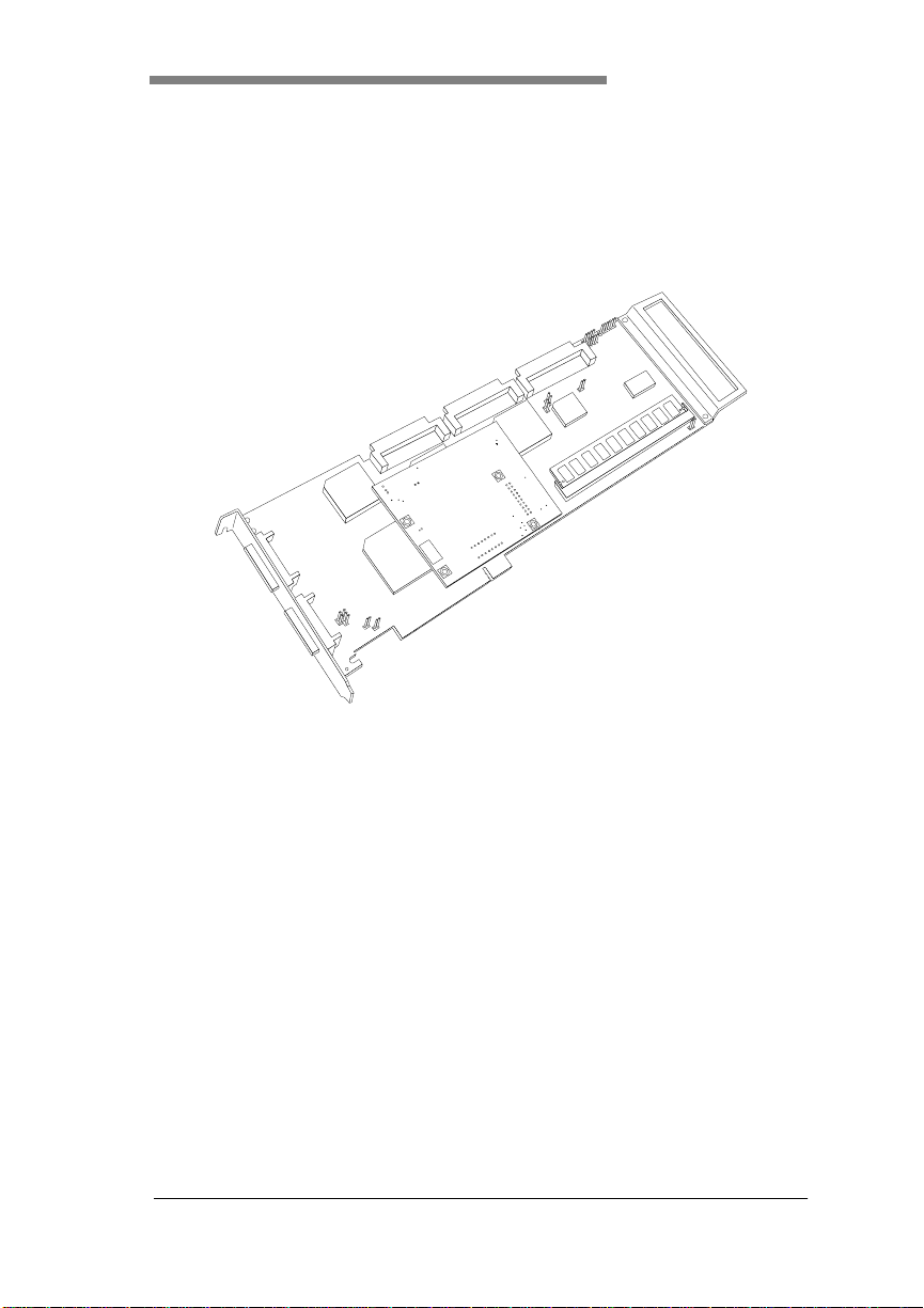
Figure 1-1. DAC960PG Three-channel RAID Controller
The DAC960PG is a 1, 2, or 3-channel, high performance, PCI to UltraSCSI RAID controller. Some of the features which are supported by the
DAC960PG controller include:
• The ability to add capacity on-line while maintaining continuous
access to data
• Automatic error recovery
• Intelligent cache battery backup option to monitor and maintain
optimum battery condition
• Mixed SCSI implementations per channel (8 and 16 bit, fast and
Ultra-SCSI)
• Disconnect/reconnect to optimize SCSI efficiency
• Tagged command queuing for improved multitasking I/O
performance
Manual No. 771971 1-1
Page 16

Product Description
• Scatter/gather for additional command efficiency
• Hot standby disk support— a drive is ready to take over if a drive in
the array should fail
• Automatic sector remapping for recovery of and protection against
defective media
• User definable rebuild priority
• SMART capable drive support for predictive failure analysis
• SAF-TE fault/status management support
• Support for tape and CDROM devices
This controller supports 1, 2, or 3 wide Ultra-SCSI channels and uses a
Mylex BA-81C15 SCSI interface chip on each channel. A 33Mhz Intel
80960 RP processor is used to off-load on-board CPU functions from the
host computer’s main CPU. The RP version of the i960 contains a bridge
between the host (primary) PCI bus and a secondary PCI bus, which
interfaces with up to 3 SCSI buses via the BA-81C15 chip(s).
The DAC960PG firmware resides in flash EEPROM. When the system is
started, the firmware is copied into RAM and executed from there. The
firmware supports RAID levels 0, 1, 0+1, 3, 5, and JBOD (Mylex RAID 7).
The DAC960PG supports disk caching with up to 128 MB of Extended Data
Out (EDO) RAM. The cache is controlled by a MYL-86138 RAID
Coprocessor ASIC, which handles ECC (Error Correction Code).
m
Caution
The only cache memory supported on the DAC960PG
is EDO ECC RAM. The EDO ECC RAM module
used must be from a Mylex quali fied vendor li st. NonMylex supplied RAM modules are not supported.
1-2 DAC960PG Installation Guide
Page 17
Introduction
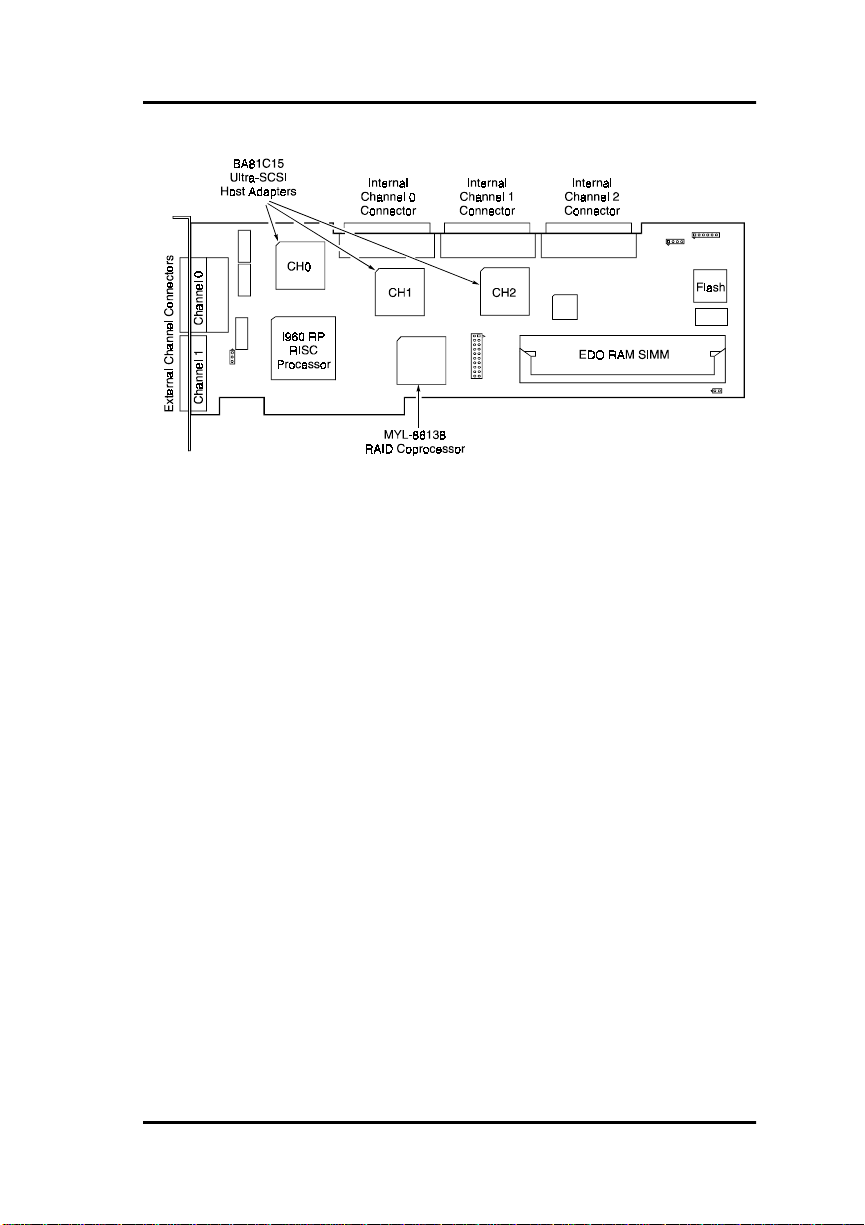
Figure 1-2. DAC960PG Con troller Component Layo ut
1, 2, or 3 connectors on the top ed ge of the DAC960PG prov ide the interf ace
for internal SCSI devices. SCSI Channel 0 (and Channe l 1 if installed) is
also available on the end of the card for connecting to external disk array
enclosures or other SCSI devices.
The DAC960PG controller uses a 32-bit RISC-based microprocessor, ASIC
logic arrays, and dedicated read/write cache memory to reduce the host
system’s CPU load and to increase disk I/O throughput (up to a 50 MB/
second sustained PCI transfer rate).
On-board memory required for operation is an EDO ECC (72 pin, 40 bit)
SIMM module. DAC960PG controllers equipped with EDO ECC RAM
deliver enhanced performance through zero wait-state CPU/SIOP burstcycle transfers between the DAC960PG cache and the host system. The
memory configuration on DAC960 PG cont rollers may be 4, 8, 1 6, 32, 64 , or
128 MB (60 ns, 0 wait states).
Manual No. 771971 1-3
Page 18
Standard Package Contents
Standard Package Contents
• DAC960PG PCI to Ultra-SCSI RAID controller with cache memory
and Installation Guide manual
Note
☛
A minimum of 4MB of memory is required for
operation of the DAC960PG.
• Configuration and Utilities software (DACCF 4.70 or g reater)
diskette and manual for controllers using firmware 4.x.
• DAC Software Kit (NOS driver software version 1.06 or greater)
diskettes and manual
• Global Array Manager (GUI sof tware v2.10 or greater ) diskettes and
manual
Options
• Intelligent Battery Backup Unit (IBBU)
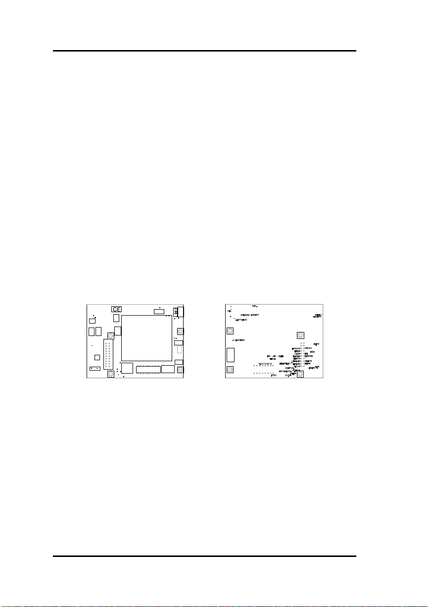
Figure 1-3. Intelligent Battery Backup Unit (IBBU)
User-Supplied Items
• SCSI cables (internal), one per channel
• SCSI cables (external) as required
• 68-pin to 50-pin SCSI adapters as required
• Terminators (internal and/or external), as required
1-4 DAC960PG Installation Guide
Page 19

Introduction
Controller Functions and Features
Key Features
The key features of the DAC960PG include:
• Configuration on Disk (COD)
• Add Capacity
• RAID/SCSI Disk Array Management
• Automatic RAID Functions
• Automatic On-board SCSI Termination
• Enhanced System Performance
• Increased System Availability
• Multiple Operating System Support
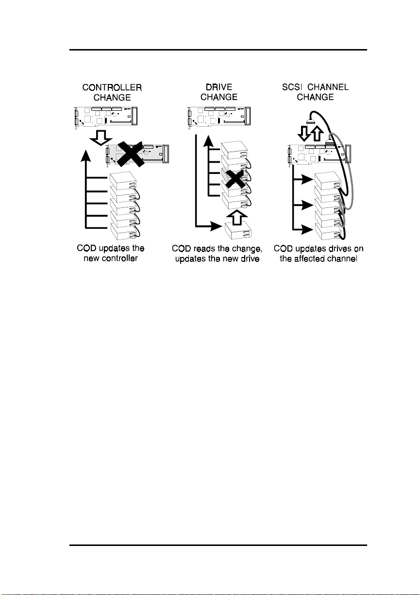
Configuration On Disk
Disks and controllers will automatically reconfigure if the system is powered
off and any of the following changes are made, and the system is
subsequently restarted. Operator intervention is not needed, unless a major
change such as RAID level, stripe size, or array size is made.
Any combination of the following changes can be performed.
1. Drives in an array can be removed and reinstalled in any order (target
IDs can be switched within an array).
2. The drives’ SCSI channel assignments can be changed.
3. A DAC960PG controller can be exchanged with another DAC960
controller as long as both controllers have 4.x or higher firmware.
Add Capacity
Add Capacity allows the user to add one or more drives to an existing array
to expand the capacity of the array. This will not increase the size of a
logical drive, but will create additional space in which to add a new logical
drive. The user is not required to take the array off-line or reformat the array.
Performing a backup as a normal operation is always recommended prior to
adding capacity.
Manual No. 771971 1-5
Page 20

Controller Functions and Features
RAID/SCSI Disk Array Management
• Supports multiple RAID levels (0, 1, 3, 5, and 0 + 1) allowing the
user to select the desired combination of storage capacity, data
availability (redundancy) and I/O transfer performance for any data
application
• Connects up to 45 SCSI drives that can be grouped and managed as
a single, large-capacity logical drive (up to 2 TeraBytes), as multiple
large-capacity drive groups, or as individual drives (with a
maximum of 32 system drives)
• Up to eight DAC960PG cont rollers per host co nnect up to 180 SCS I
devices
• Industry-standard Fast/Wide Ultra-SCSI interface supports most
SCSI drives
Automatic RAID Functions
• Automatic failed drive detection
• Automatic rebuild of the array using stand-by (ho t spare) disk after a
drive failure
• Transparent drive rebuild permits automatic rebuild of failed drives
during normal operation without having to take the array off-line
• Automatic error detection/correction of parity errors, bad blocks,
etc.
• Automatic sector remapping recovers defective media and corrects
data errors
Automatic On-board SCSI Termination
• No jumpers to set
• Automatic internal and external bus detection on each channel
• On-board termination automatically enabled or disabled
• Improved ease of hardware configuration allows reconfiguration of
channels without removing DAC960 P G from host
1-6 DAC960PG Installation Guide
Page 21

Enhance SCSI Performance
• Fast/Wide Ultra-SCSI channels provide high-performance data
transfers at up to 40 MB/second/channel
• PCI bus mastering provides up to 132 MB/second burst data rates
• Tag-queuing to the drives allows processing of up to 64
simultaneous multi-thread system commands or data requests
• User-defined performance-tuning through selectable cache write
policy, variable stripe width, and rebuild priority to optimize
controller performance during rebu il d
• Disconnect/reconnect capability for enhanced performance and
SCSI bus optimiza tion
Increase System Availability
• Built-in diagnostics provide controller and drive fault monitoring
during power-on and continuous operation
• Status alerts notify the administrator or user of critical conditions
• Supports SCSI Accessed Fault-Tolerant Enclosures (SAF-TE)
protocol for integrated monitoring of enclosure power supplies, fans
and temperature
Introduction
• Battery backup option protects data in the controller cache in the
event of a power interruption
Operating System Support
• Microsoft Windows NT 3.51 and NT 4.0
• Novell NetWare 3.12 or 4.xx
• IBM OS/2 3.0 (WARP), and SMP
• SCO UNIX 3.2.4, ODT, and OSR 5.0
• SCO UnixWare v2.1
• MS-DOS 5.x, 6.x, and above
• Microsoft Windows 95 — for client Global Array Manager (GAM)
only
Manual No. 771971 1-7
Page 22

DAC960PG Specifications
DAC960PG Specifications
Controller
CPU Intel i960 RP® RISC 32-bit microprocessor, 33MHz
Memory
Module Type EDO ECC RAM, 60ns, 72-pin SIMM,
Size Minimum: 4 MB
Cache
Write: Selectable, Write Through or Write Back
Read: Always enabled
Error Protection Error Correction Code (with 40-bit EDO RAM)
Firmware
ROM Type Flash EEPROM, 256K x 8
PCI
I/O Processor Imbedded in Intel i960 RP microprocessor
Transfer Rate Up to 50 MBytes/second (synchronous)
SCSI
I/O Processors Mylex BA-81C15, one per channel
(Levels supported) RAID 0, Striping
RAID
DAC960PG
n
qualified vendor list - contact customer service for a list
of approved memory components)
Optional: 8, 16, 32, 64, or 128 MB
RAID 1, Mirroring
RAID 3, Parity
RAID 5, Parity
RAID 0 + 1, Striping and Mirroring (Mylex RAID 6)
JBOD, Single-drive control (Mylex RAID 7)
x 40 (from a
1-8 DAC960PG Installation Guide
Page 23

Specifications (continued)
Electrical requirements
5V ± 5% @ 3.5 Amp (Max. plus cable termination power)
Environmental
Temperature Operating: 0°C to +55°C
(+32°F to +131°F)
Storage: -20°C to +70°C
(-4°F to +158°F)
Humidity Operating: 10% to 90% rh
(non-condensing) Non-operating 10% to 90% rh
Altitude Operating: Up to 10,000 ft. (3,048 m)
Non-operating Up to 50,000 ft. (15,240 m)
Form Factor
Length 12.283 inches
Width 4.2 inches
Maximum Component Height
.105 inches
Board Width with IBBU
Will not exceed the width of one PCI slot
Introduction
Manual No. 771971 1-9
Page 24

DAC960PG Specifications
1-10 DAC960PG Installation Guide
Page 25
Overview
Chapter 2
Functional Description
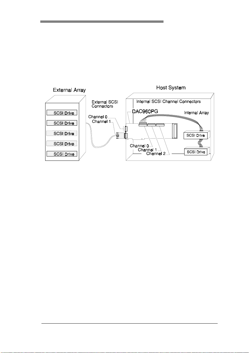
Figure 2-1. System Diagram
Controller Components
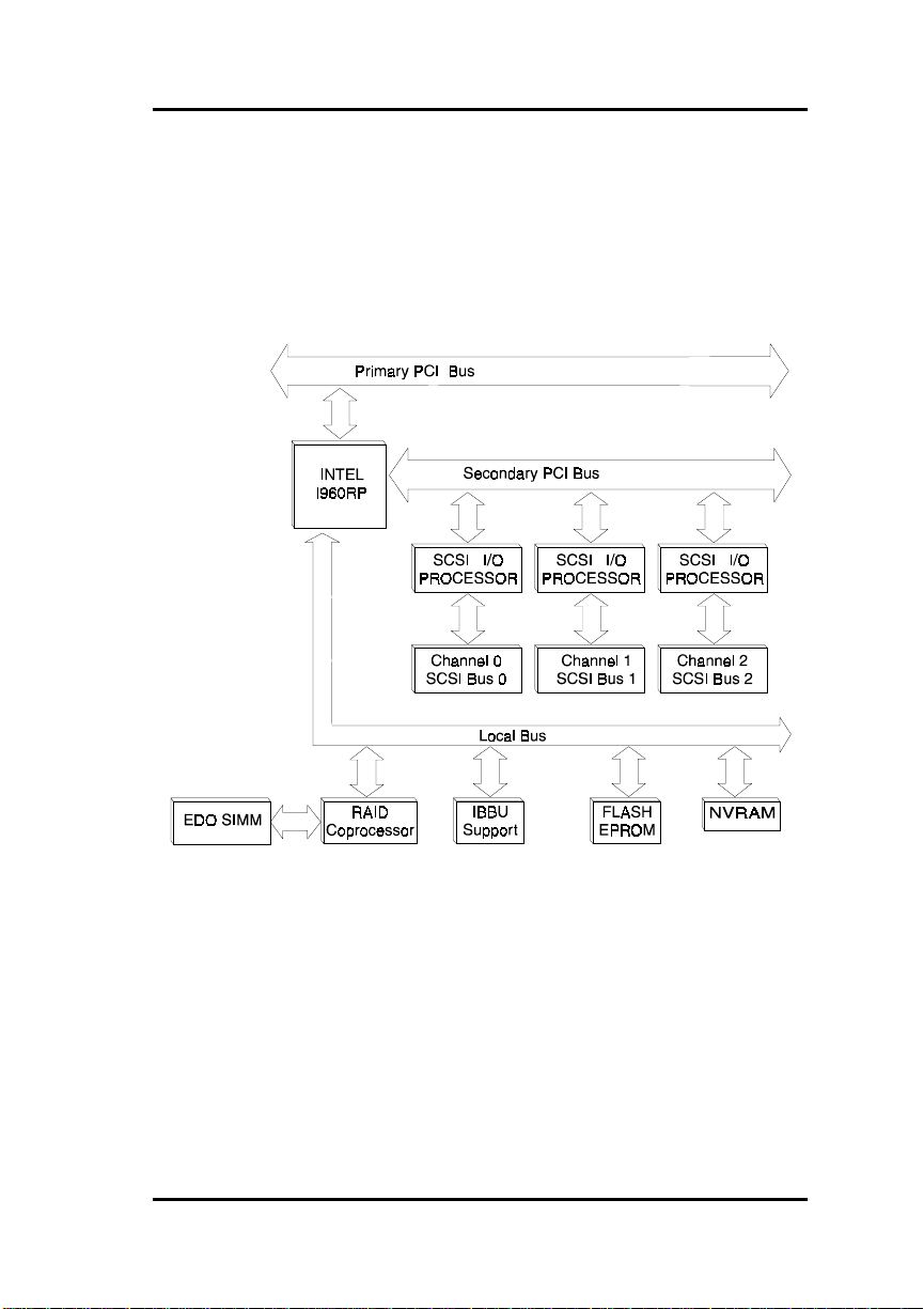
The I960 RP Processor
The Intel 80960RP processor chip is the heart of the DAC960PG controller.
The i960 RP is a CPU that arbitrates the primary and secondary PCI busses,
the Ultra-SCSI interface, cache memory control, firmware control, and
NVRAM data; thereby freeing the host’s CPU for other tasks.
The RP of the
contains an interface between the primary PCI bus (PCI connection to host)
and the secondary PCI bus. The secondary PCI bus is routed to one, two, or
three Mylex BA-81C15 PCI to Ultra SCSI Host Adapter Chips (one chip for
each Ultra-SCSI channel).
The i960 RP contains a memory controller that is used to control the
firmware flash EEPROM and the NVRAM. The i960’s memory c ontroller is
not used to control the cache memory in this application.
Manual No. 771971 2-1
i960 RP
designation represents the part of the chip that
Page 26

Controller Components
Cache Memory Subsystem
The DAC960PG requires a
to operate and up to 128 MB of memory can be installed. The physical
memory configuration for the DAC960PG is one 72-pin SIMM.
The DAC960PG supports EDO (Extended Data Out) RAM. EDO RAM is a
type of DRAM that has a performance level approaching that of Static RAM.
The maximum amount of EDO RAM is 128 MB.
The memory subsystem supports the ECC (Error Correction Code) form of
error protection. ECC requires the use of 40-bit EDO RAM SIMMs.
The cache memory is controlled by a Mylex MYL-86138 RAID
Coprocessor ASIC.
Cache memory write policy can be configured by software as either Write
Through or as Write Back.
Cache memory data can be protected in the event of a power outage by an
optional battery backup unit.
,
WARNING
Do not attempt to install, remove, or change a
cache SIMM on the DAC960PG with the IBBU
installed. Serious damage to the S IMM and/or the
battery backup unit will occur if this precaution is
not followed.
minimum of 4 MB
of on-board cache memory
Controlle r Firmware
The DAC960PG firmware contains the programs executed by the i960RP
CPU. The Firmware resides in the on-board Flash EEPROM and operates
from DRAM after the firmware is uncompressed and downloaded from the
EEPROM. The EEPROM retains information after power is off and can also
be re-written, to allow the controller firmware to be upgraded without the
need to replace any hardware chips.
2-2 DAC960PG Installation Guide
Page 27
Functional Description
The NVRAM stores data on the current configuration of the controller and
its attached disk drives, and lists of pending write operation s issued to any
redundant drives. As the configurations change (for example, when a drive
fails), the NVRAM keeps a record of the changes. These data are checksum
protected so that after a power failure, the controller will recall the
configuration and will restore consiste ncy for all outstanding writes on
restart.
Figure 2-2. DAC960PG Controller Block Diagram
PCI Bus Interface
The PCI bus interface is contained in the Intel 80960RP intelligent I/O
processor, and conforms to PCI Specification Rev 2.1. The RP in the
designation specifically means that such an interface is included on the
RP
i960
chip (as opposed to other i960s). The i960 RP connects directly to the
primary PCI bus and is a bridge to the secondary PCI bus. The primary and
secondary PCI busses are clocked at PCI bus speed. The secondary PCI bus
interfaces with up to three Mylex BA81C15 PCI to Ultra-SCSI host adapter
ASICs. Each BA81C15 is dedicated to one Ultra-SCSI channel.
Manual No. 771971 2-3
Page 28

Controller Components
Ultra-SCSI Bus Interface
The three Ultra-SCSI channels can be simultaneously accessed by dedicated
BA81C15 PCI to Ultra-SCSI ASICs. Each channel supports up to 15
physical SCSI drives. The DAC960PG suppo rts Wide Ult ra- SCSI as well as
earlier SCSI standards. The DAC960PG delivers SCSI data transfer rates up
to 40 MB per second per channel.
Configuration on Disk
Firmware 4.x provides Configuration on Disk (COD). COD allows a RAID
equipped computer to detect certain hardware changes when they occur, and
automatically reconfigure accordingly. Automatic reconfiguration occurs
after hardware changes such as:
• Change of controller card in the event of a controller failure, or if a
controller with more channels is needed
• Change of target IDs (relocating drives) or replacement of drives
• Interchange of cables
The configuration information is stored in the last 128 sectors of every
working physical hard disk This area is reserved by Mylex for this purpose.
Management of Bad Data
Firmware 4.x supports the handling of data that cannot be reconstructed at
the time of a rebuild. A Bad Data Table is maintained in memory. Whenever
a change is made to the table, the table is saved on all disks in the
configuration.
Bad Data Table entries are made during the rebuild and add capacity
processes. If a bad sector is encountered, a sector-by-sector scan is initiated
on the stripe in which the error occurred. The corresponding system sector
number is inserted into the Bad Data Table, and the sector is immediately
overwritten with an arbitrarily selected pattern, making it invalid for reading.
Subsequent read operations check the Bad Data Table to determine whether
any of the blocks about to be read are bad data blocks. If this is the case, an
error condition is returned.
Subsequent write operations check the Bad Data Table to determine wheth er
any of the blocks about to be overwritten are bad data blocks. If this is th e
case, the blocks are deleted from the Bad Data Table and the data is written
to the disk.
2-4 DAC960PG Installation Guide
Page 29

Functional Description
Separate Disk-stripe Size and C ache-line Size
Firmware 4.x supports the configuration of disk-stripe sizing and cache-line
sizing independently. This g ives the user more flexibility in adjusting
performance. This can be set using the DACCF utility version 4.7 or greater.
System Drive Size Extensions
Firmware 4.x supports system disk drive sizes of up to 2 TeraBytes.
Support for Additi onal Target IDs per Channel
Firmware 4.x supports up to 15 target IDs per channel. The IDs must range
from 0-6, and 8-15. Target ID 7 on each channel is reserved for the
controller.
Support for up to 32 Syst em Drives per Controller
Firmware 4.x supports up to 32 system drives that can be configured on up
to 45 physical drives per controller (assuming the controller has three
channels).
Manual No. 771971 2-5
Page 30

SCSI Functions
SCSI Functions
The DAC960PG manages and controls the SCSI bu s arbitration b etween th e
controller and its connected devices, and all SCSI activity of the connected
devices.
Multiple SCSI Format Support
The standard DAC960PG provides at least one, and optionally up to three,
SCSI channels for connecting disk drives or other d evices, such as CD-ROM
and tape drives. With the correct cabling, these devices may be any
combination of Narrow or Wide, standard or FAST SCSI or Ultra-SCSI
formats (see Table 2-1).
Table 2-1. Supported SCSI Types
SCSI Type Clock Rate Data Rate
Ultra-SCSI
(16-bit)
Ultra-SCSI
(8-bit)
Wide SCSI-2
(16-bit)
Narrow SCSI-2
(8-bit)
SCSI-1 (8-bit) 5Mhz 5MB/sec
20 Mhz 40 MB/sec
20 Mhz 20 MB/sec
10 Mhz
5 Mhz
10 Mhz
5 Mhz
20 MB/sec
10 MB/sec
10 MB/sec
5 MB/sec
SCSI Cabling and Termination Conventions
Disk drives equipped with a SCSI interface should be connected to the
controller by means of cables that comply with standard SCSI data-rate,
pinout, and cable-length conventions (including all internal wiring). Up to
15 SCSI devices can be connected to each of the controller’s drive channels.
Disk drives at the end of each SCSI bus on a channel must be terminated.
There are no termination jumpers on the DAC960PG. If the DAC960PG is
situated at one end of the channel, it will automatically sense a termination
requirement and properly set its own termination. If the DAC960PG is
located between an internal and external SCSI bus on a channel, it will not
install termination for itself. The DAC960PG supports active termination
(alternative-2, or ALT-2).
2-6 DAC960PG Installation Guide
Page 31

Functional Description
SCSI Address (Target ID) Selection
Each drive or device on a specific SCSI channel must be configured for a
target address (or target ID) that is different from all other devices on that
channel. The target ID, a SCSI address number from 0 to 15, is assigned to
each device attached to a SCSI channel during installation.
The default SCSI address for the DAC960PG controller is target ID 7.
Subsequently, you must assign to each connected disk drive a different
(unique) SCSI address, ty pically a target ID nu mber from 0 throu gh 15 (with
the exception 7, which is reserved on each channel for the controller).
Manual No. 771971 2-7
Page 32

Drive Organization
Drive Organization
The DAC960PG controller organizes the SCSI drives connected to it as
physical drives and logical units.
Physical Drives (Drive Groups or Packs)
Using the DAC960PG up to eight indivi dual disk drives can be used together
to form a pack or
the array’s logical unit capacity.
☛
To determine the total size of a drive group, multiply the size of the smallest
drive in the drive group by the number of disk drives in the group.
For example, if there are four drives of 4 GB each, and one drive of 2 GB
comprising a drive group, the effective capacity available for use is 10 GB
(5 x 2),
The DAC960PG supports up to eight (8) drive groups.
not
drive group
Note
If all of the disks in a drive group are not the same
size, the drive group has the effective capacity of the
smallest drive in the group times the number of
drives.
18 GB.
of physical drives that will be used to comprise
Logical Drives (System Drives)
A logical drive (or system drive) is that portion of a drive group (or a
combination of up to eight drive groups) seen by the host system as a single
logical device. The maximum addressable size of a single logical drive is
2TB.
Note
☛
Use the DACCF software utility or the Global Array
Manager (GAM) to configure the logical drives
(system drives).
2-8 DAC960PG Installation Guide
Page 33
Functional Description
Configuration on Disk
Figure 2-3. Configuration on Disk Examples
Firmware 4.x provides Configurat ion on Disk (C OD), which allows a RAID
equipped computer to detect certain hardware changes on power-up or reset
and automatically reconfigure accordingly.
Mylex Format
The necessary configuration information is stor ed in NVRAM on the
controller as well as on the last 128 sectors on every hard disk that is
currently part of the controller’s configuration. This format with
configuration information stored in the last 128 sectors of a disk is a unique
Mylex format.
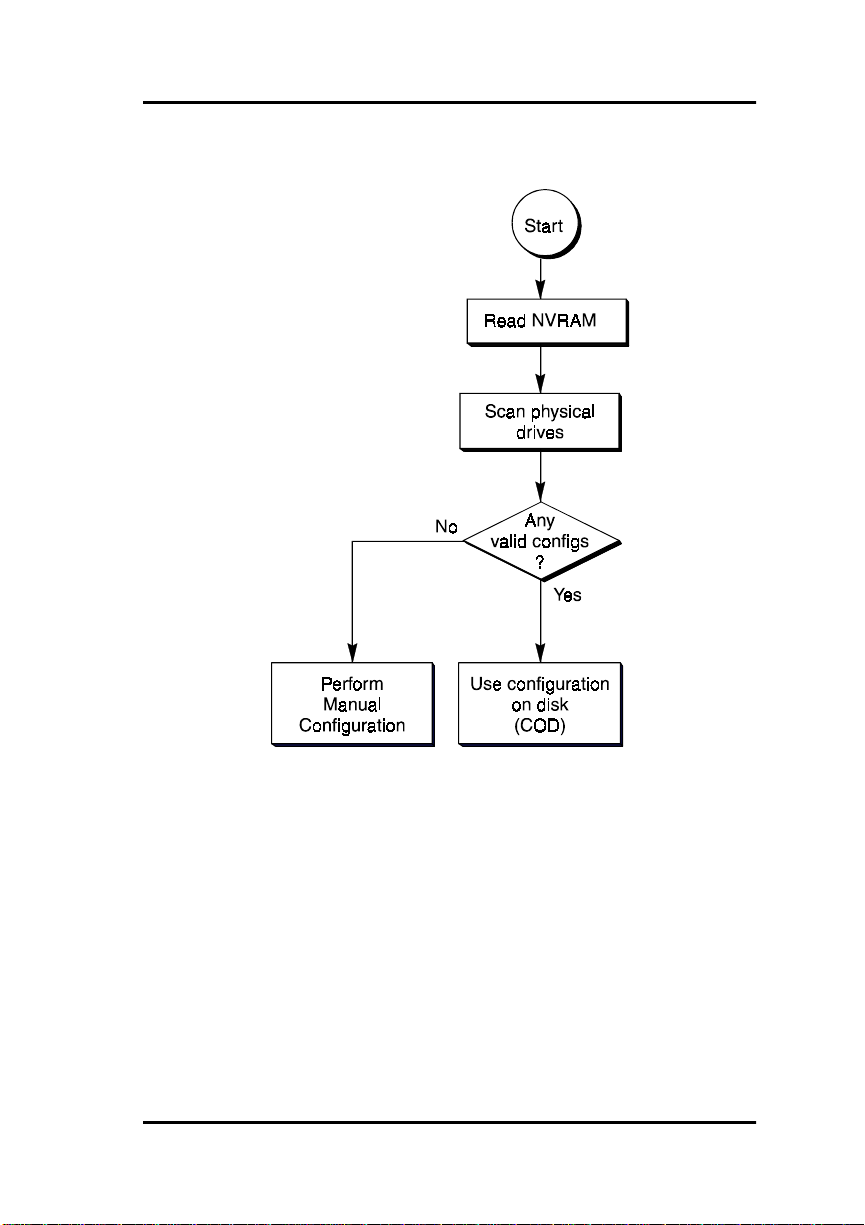
Determining the Configuration to be Used
On start-up, the configuration information is read from NVRAM on the
controller. This information is used to detect all physically connected and
responding drives during a drive scan. The disk configuration header read
from each drive is compared with the reference configuration header in
NVRAM.
Manual No. 771971 2-9
Page 34

Drive Organization
If there is a mismatch, it means the device just read is an unidentified device.
If a configuration header is not in the Mylex format, the correspon ding drive
is assumed to be new. Such a drive is also unidentified. If all drives
connected to the controller are unidentified, the configuration is assumed to
be new, and the controller initializes all drives as Mylex COD compat ible
drives.
After the controller scans all possible drives, the header information from all
drives exists in memory. The headers are scanned to determine if there is a
valid configuration. If a configuration matches the controller’s NVRAM, it
is selected for use. If a configuration matches the NVRAM, but the sequence
number is different, then the configuration with the highest sequence num ber
is used. If no configuration matches the controller’s NVRAM , then the
configuration (if any) that occurs the greatest number of times is the
configuration that is used. If no valid disk configurations can be found, then
the configuration in NVRAM is used, and the Bad Data Table is cleared. A
configuration is selected from disk in all oth er cases, and the Bad Data Table
is read from a disk with the selected configuration.
Device Translation Table
The selected configuration becomes the basis for a device translation table.
This table is generated during the verification scan. Configuration headers
are read at this time to determine if any drive slot (target ID) changes, cable
swaps, or controller changes have occurred since the last verification scan.
At this time it is also determined whether or not any drives are missing. An
attempt is made to map any missing drives to their original slots. If the
present controller determines that the present physical configuration makes
this illegal, then the affected missing drive is assig ned the first free slot
(either a non-responding slot or a slot with a non-Mylex drive in it).
If a legal configuration cannot be created, an installation abort condition
occurs, and the DAC configuration utility needs to be invoked. For more
information, refer to the
Manual
2-10 DAC960PG Installation Guide
.
DACCF Utilities Installation Guide and User
Page 35
Functional Description
Figure 2-4. Configuration on Disk Flowcha rt
Manual No. 771971 2-11
Page 36

RAID Management
RAID Management
RAID is an acronym for Redundant Array of Independent Disks. The
DAC960PG controller implements several different versions of the Berkeley
RAID technology, and two special versions that are specific only to the
DAC960 family of RAID controllers. Each version (referred to as a RAID
Level) that is supported by the DAC960PG is shown in Table 2-2.
An appropriate RAID level is selected when the logical drives are defined or
using a configuration software utility such as
created
DACCF
which RAID level to use is based on the following priorities:
An appropriate RAID level is selected when the logical units are defined or
created. This decision is based on disk capacity, data availability (fault
tolerance or redundancy), and disk performance.
The DAC960PG makes the RAID implementation and the disks’ physical
configuration transparent to the host operating system. This means that the
host operating system drivers and software utilities are not affected,
regardles s of th e RAI D le v e l se le c t ed.
Correct installation of the disk array and the DAC960PG requires a proper
understanding of RAID technology and the concepts described in this
chapter and in the DACCF Utilities documentation.
. Deciding
Table 2-2.
RAID
Level
JBOD “Just a Bunch of Disks (Mylex RAID 7).” Each drive
2-12 DAC960PG Installation Guide
Description
0 Block striping is provided, which yields higher perform-
ance than with individual drives. There is no
redundancy.
1 Drives are paired and mirrored. All data is 100% dupli-
cated on an equivalent drive (fully redundant).
3 Data is striped across several physical drives. Parity
protection is used for data redundancy.
5 Data is striped across several physical drives. Parity
protection is used for data redundancy.
0+1 Combination of RAID levels 0 and 1 (Mylex RAID 6).
Provides striping and redundancy through mirroring.
operates independently like with a common host bus
adapter. No redundancy is provided.
Supported RAID Levels
Drives/Group
Min Max
2 8
2 2
3 8
3 8
3 8
1 1
Page 37
Functional Description
RAID Techniques and Terms
The techniques of disk striping, mirroring, and parity (redundancy) are
fundamental elements of RAID technology performed by the DAC960PG.
More detailed information on how to apply these techn iques can be fou nd in
the
DACCF Utilities Installation Guide and User Manual
manual.
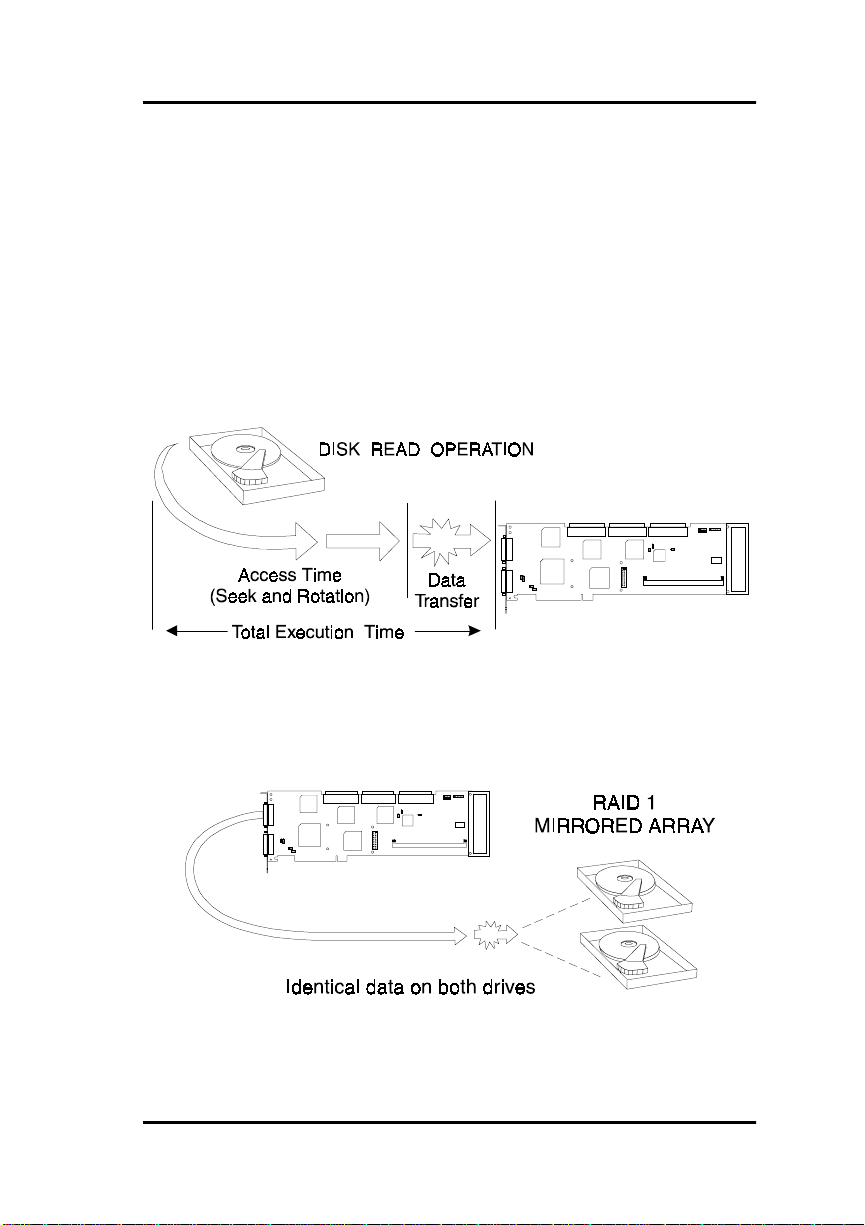
JBOD (No RAID)
JBOD is an acronym for Just a Bun c h Of Disks. The disks function
independently of one another, just as they would on a non-RAID SCSI
controller.
Figure 2-5. Typical JBOD Disk I/O Activity
. or the
GAM
Mirroring (RAID 1)
Mirroring refers to the 100% duplication of data from one disk drive onto
another. Each disk contains the mirror image of the data on the other drive.
Figure 2-6. A Mirrored Drive Group
Manual No. 771971 2-13
Page 38

RAID Management
Striping (RAID 0)
Striping refers to the storing of a sequential block of incoming data across
multiple drives in a drive group. For example, if there are three drives in a
drive group (or pack), the data will be separated into blocks. Block o ne of
the data will be stored on drive one, blo c k two on drive two, block three on
drive three. Drive one will again be the location o f the next block (block
four); then, block five is stored on drive two, block six on drive three, and
so on. This method can significantly increase disk system throughput,
particularly for transferring large, sequential data blocks.
Figure 2-7. Block Striping
Figure 2-8. Drive Group Mapped for Block Striping
2-14 DAC960PG Installation Guide
Page 39
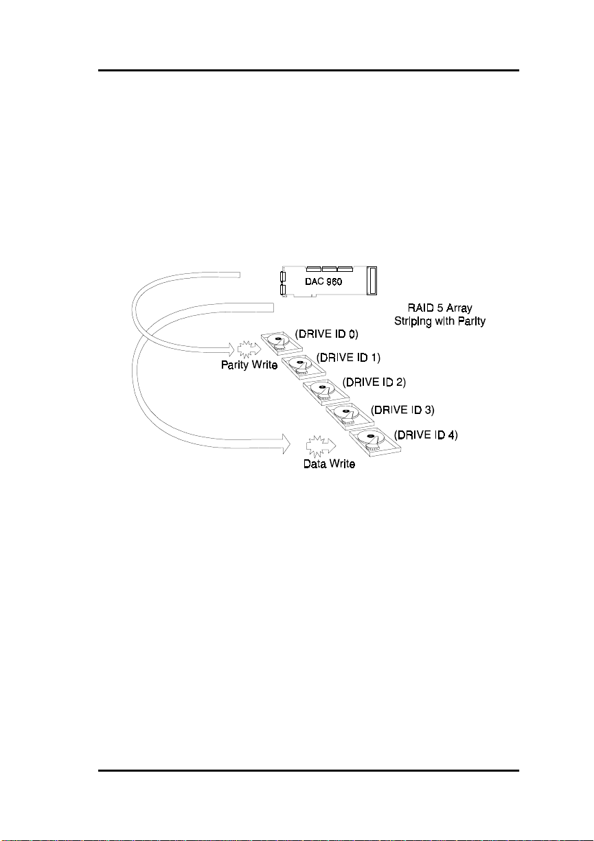
Functional Description
Striping with Parity (RAID 3 and RAID 5)
Striping with parity (rotated XOR redundancy) is a method of providing
complete data redundancy that requires only a fraction of the storage
capacity than mirroring for storing redundant information.
In a system configured under RAID 3 or RAID 5 (which requires at least
three SCSI drives), all data and parity blocks are divided between the drives
in such a way that if any single drive is removed (or fails), the data on the
missing drive can be regenerated using the data on the remaining drives
(XOR refers to the Boolean “Exclusive-OR” operator).
Figure 2-9. Drive Group Mapped for Block Striping with Parity
Manual No. 771971 2-15
Page 40
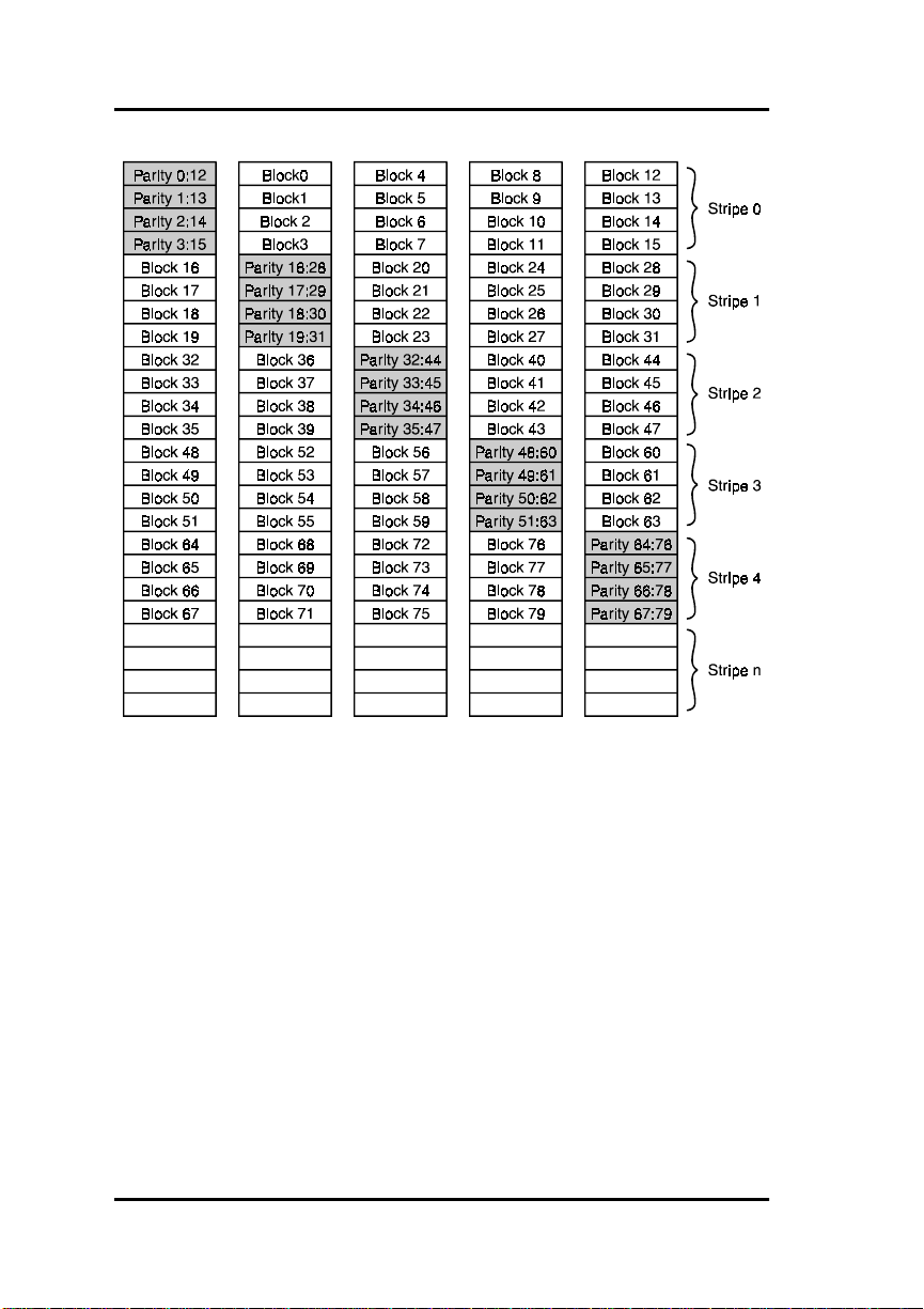
RAID Management
Figure 2-10. Block Striping with Parity (RAID 5 standard)
2-16 DAC960PG Installation Guide
Page 41

Functional Description
Striping with Mirroring (RAID 0+1)
RAID 0+1 (Mylex RAID 6) is a combination of RAID 0 (striping) and
RAID 1 (mirroring).
The advantages of RAID 0+1 are ful ly mirro red data and bette r perfor mance
than RAID 1. The disadvantage of RAID 0+1 is its 50% utilization capacity
(if all drives are the same size).
Disk 0 Disk 1 Disk 2
Stripe 0
Sectors 0-F
Stripe 2
Sectors 20-2F
Stripe 3
Sectors 30-3F
Stripe 5
Sectors 50-5F
Stripe 1
Sectors 10-1F
Stripe 0
Sectors 0-F
Stripe 4
Sectos 40-4F
Stripe 3
Sectors 30-3F
Stripe 2
Sectors 20-2F
Stripe 1
Sectors 10-1F
Stripe 5
Sectors 50-5F
Stripe 4
Sectos 40-4F
Striping Terminology
Stripe Width
The number of drives within a drive group is referred to as the stripe width.
Stripe Order
The order in which SCSI drives appear within a drive group is the stripe
order. It is critical that the selected stripe order is always maintained, to
assure data integrity and the controller's ability to rebuild failed drives.
Stripe Size
The size of the logically contiguous data block recorded on each drive within
a logical unit is the stripe size. The default is 8 KBytes. Other choices are 16,
32, or 64 KBytes, which may be selected from the DACCF configuration
utility (Advanced Functions menu, Physical Parameters option), or from the
GAM.
Larger stripe size ensures better performance for large sequential data
transfers. Smaller stripe size is best suited for small random data transfers.
Manual No. 771971 2-17
Page 42

Drive Management
Drive Management
The DAC960PG functions that monitor and control the operation of the
physical drives and logical units are instrumental to the controller’s ability to
perform RAID management and automated error recovery tasks.
Controlling Physical Drive States
The
status. At any given time, a SCSI drive can be in one of several states: ONLINE, STANDBY, READY, DEAD, REBUILD, or WRITE-ONLY.
The controller stores the state of the attached SCSI drives in its non-volatile
memory. This information is retained even after power-off. If a SCSI disk is
labeled DEAD in one session, it will stay in the dead st ate until a change is
made either by using a system level uti lity or after a maintenance/rebuild
procedure is performed.
of a physical drive refers to a SCSI drive's current operational
state
On-line (ONL)
A SCSI drive (physical drive) is
1. Is power ed on
2. Has been defined as a member of a drive group
3. Is operating properly.
on-line
if it:
Standby (SBY)
A SCSI disk drive is in a
1. Is power ed on
2. Is able to operate properly
3. Has
4. Has been defined as a standby
been defined as part of any drive group.
not
standby
state if it:
Dead (DED)
A drive is
1. Is not present
2. Is present, but not powered on
3. Failed to operate properly and was kill ed by the controller
2-18 DAC960PG Installation Guide
if it was previously configured, but:
dead
Page 43

Functional Description
When the controller detects a failure on a disk, it
its state to dead. A SCSI drive that is in the dead state does not participate in
any I/O activity. No commands are issued to dead drives.
that disk by changing
kills
Write-Only (WOL)
A SCSI drive is in a
that is ...
• During a RAID 1 rebuild process, data is copied from the mirrored
drive to the replacement drive.
• During a RAID 3, RAID 5, or RAID 0+1 rebui ld, data is regenerated
via the XOR redundancy algorithm and written to the replacement
drive.
... and the rebuild was terminated abnormally before it completed.
write-only
state if it was in the process of being rebuilt,
Ready (RDY)
A SCSI disk drive may be identified by the DACCF utility as
1. Is power ed on
2. Is able to operate properly
3. Has
4. Has
Ready
drive will change from RDY to SBY (standby) when the configuration is
saved to memory.
been defined as part of any drive group.
not
been defined as a standby
not
is not an actual drive state or command issued by the controller. The
ready
if it:
Controlling Logical Unit States
The state of a logical unit on a DAC960PG can be ON-LINE, CRITICAL, or
OFF-LINE. Notice that the same term
drives and logical units.
Note
☛
I/O operations can be performed only with logical
units that are either
on-line
On-line
A logical unit is
Manual No. 771971 2-19
if all of its participating physical drives are on-line.
on-line
is used for both physical
on-line
or
critical
.
Page 44

Drive Management
Critical
A logical unit is considered
when any failure of another of its
critical
physical drives may result in a loss of data.
A logical unit is
if it meets both of the following conditio ns:
critical
1. It is configured for RAID 1, RAID 3, RAID 5 or RAID 0+1
2. One (and no more than one) of its physical drives is
(refer to the description of
Off-line
, below.
not
on-line
Off-line
An
logical unit is one on which no data can be read or written. No
off-line
operations can be performed on off-line logical units. System commands
issued to off-line logical units are returned with an error status.
1. A logical unit can be off-line under one of two conditions :
2. It is configured with a redundant RAID lev el (1, 5, or 0+1) and two or
more of its SCSI drives are
not
on-line
3. It is configured as RAID 0 or JBOD (or in a spanned set) and one or
more of its SCSI drives are
not
on-line.
Controlling Standby Replacement Drives (Hot Spares)
The
standby replacement
features the DAC960PG provides to achieve automatic, non-stop service
with a high degree of fault-tolerance. With the standby rebuild function, the
controller performs a rebuild operation automatically when a SCSI disk
drive fails and both of the following conditions are true:
drive, or
hot spare
, is one of the most important
1. A standby SCSI disk drive of identical or larger size is found attached
to the same controller;
2. All of the system drives that are dependent on the failed disk are
redundant system drives, e.g., RAID 1, RAID 3, RAID 5, or
RAID 0+1.
During the automatic rebuild process, system activity continues as normal.
System performance may degrade slightly, however, during a rebuild.
2-20 DAC960PG Installation Guide
Page 45

Functional Description
Using Standby Rebuild
To use the automatic standby rebuild feature, it is necessary to always
maintain a standby disk in the system.
A
standby
disk can be created when the DAC960 PG configur ation is cr eated
or changed using the DACCF software utility, all d isks attached to the
controller that are
On-line
and not assigned to a drive group will be
automatically labeled as standby disks.
Hot-Swap Drive Replacement
The DAC960PG supports the ability of certain drive enclosures to perform a
hot-swap
drive replacement while the system is on-line. A disk can be
disconnected, removed, or replaced with a different disk without taking the
system off-line. The SCSI bus termination must be arranged so that a drive
can be removed without disrupting the termination scheme.
Disk Failure Detection
The DAC960PG automatically detects SCSI disk failures. A monitoring
process running on the controller checks, among other things, elapsed time
on all commands issued to disks. A time-out will cause the d isk to be reset
and the command will be retried. If the command time-out occurs again, the
disk could be killed by the controller (that is, its state changed to dead).
The DAC960PG also monitors SCSI bus parity errors and other potential
problems. Any disk with too many errors will be killed by the controller.
Disk Media Error Management
The DAC960PG manages SCSI disk media errors in a manner tran sparent to
the user.
Disks are programmed to report errors. When a disk reports a media error
during a read, the controller reads the data f rom the mirror ( RAID 1 or RAID
0+1), or computes the data from the other blocks (RAID 3 or RAID 5), and
writes the data back to the disk that encountered the error. If the
or the following
verify-of-data
fails (media error on write), the controller
write
fails,
issues a REASSIGN command to the disk, and then writes the data to a new
location. Since the problem has been resolved, no error is reported to the
system.
Manual No. 771971 2-21
Page 46

Drive Management
When a disk reports a media error during a write, the controller issues a
REASSIGN command to the disk, and writes the data out to a new lo cation
on the disk.
Checking Disk Consistency
A consistency check is a pr ocess th at verifi es the inte grity of r edun dant dat a.
For example, performing a consistency check of a mirrored drive assures
that the data on both drives of the mirrored pair are exactly the same. To
verify RAID 3 or RAID 5 redundancy, a consistency check reads all
associated data blocks, computes parity, reads parity, and verifies that the
computed parity matches the read parity.
2-22 DAC960PG Installation Guide
Page 47

Functional Description
Cache Management
The DAC960PG provides performance enhancement of data transfers
through its on-board cache memory. The controller supports cache memory
sizes from 4 MB (minimum) to 128 MB (maximum). Cache memory is
allocated by the controller memory management functions for Read Cache
and Write Cache. Write cache policy is user-selectable for each logical unit
to achieve optimum performance within specific applications.
Read Cache
Read cache is always enabled by the controller. Its operation is transparent
and requires no user intervention.
Write-Back Cache
Write-Back Cache refers to a caching strategy whereby write operations
result in a completion status being sent to the host operating system as soon
as the cache (not the disk drive) receives the data to be written. The target
SCSI Drive will receive the data at a more appropriate time in order to
increase controller performance.
Write-Through Cache
Write-Through Cache refers to a cache writing strategy whereby data is
written to the SCSI Drive before a completion status is returned to the host
operating system. This caching strategy is considered more secure, since a
power failure will be less likely to cause loss o f data. However, a WriteThrough cache results in a slightly lower performance in most applications.
Cache Battery Backup
An optional cache battery backup is available that can be used to protect
against cache data loss in the event of a power failure.
Manual No. 771971 2-23
Page 48

Cache Management
2-24 DAC960PG Installation Guide
Page 49

Chapter 3
Installation
Installation Overview
This chapter describes the installation of the DAC960PG PCI to Ultra-SCSI
RAID controller hardware and th e proper connection and configuration of its
attached SCSI devices
Requirements
The following items are required to perform the installation:
• DAC960PG PCI to Ultra-SCSI RAID controller with memory
installed
• Host system with an available PCI slot
• Configuration & Utilities disk ette containing the DACCF utility
• SCSI cable(s) to interconnect the controller and the drives/devices
• Narrow or Wide; and Standard, Fast, or Ultra-SCSI compliant disk
drives
• SCSI termination device( s) as requi red
Refer to the Configuration & Utilities diskette file DISKLIST.TXT for a list
of disk drives and other devices that are compatible with the DAC960PG.
Optional Requirements
The following optional items also may be required, depending on your
application or the type of installation:
• SCSI cable to interconnect the controller and external devices
• Battery back-up option for controller cache memory
Manual No. 771971 3-1
Page 50

Before You Begin . . .
Before You Begin . . .
Installing the DAC960PG PCI to Ultra-SCSI RAID controller is no more
difficult than installing any PCI adapter card. Just follow these commonsense rules and the installation procedures should go flawlessly:
,
WARNING
Working with the covers off and power applied to
the system can result in shock and serious injury.
1. REMOVE POWER from the system before starting.
2. Read all of the instructions in this manual through co mpletely before
proceeding, and observe the Notes, Cautions, and Warnings.
3. Determine the system’s SCSI ID requirements and set the controller’s
NVRAM as needed before installing it.
4. Make sure that all of the cabling Pin 1 locations are correct.
5. Make sure all SCSI conventions (cable type, cable length, termination,
etc.) are correct.
6. Safety check the installation before powering-on the system.
You may copy the DAC960PG Installation Notes and Installation Checklist
in this manual to use as a quick reference guide during the installation and
configuration procedures.
3-2 DAC960PG Installation Guide
Page 51

Installation
Installation Notes:
DAC960PG PCI to Ultra-SCSI RAID Controller Setup:
There are no jumper settings on the DAC960PG to b e confi gur ed by the
user. Controller termination is automatic as long as the end o f the SCSI bus
away from the controller is properly terminated. If there are devices
connected only to an internal connector or only to an external connector of a
channel, on board termination for that channel will be au tomatically
enabled
. If there are devices connected to both the internal and external
connectors of the same channel, on board termination fo r that ch annel will
automatically be
SCSI Devices Installed:
Drive Channel 0
disabled
.
SCSI
ID
0 ___________________ ________ ______
1 ___________________ ________ ______
2 ___________________ ________ ______
3 ___________________ ________ ______
4 ___________________ ________ ______
5 ___________________ ________ ______
6 ___________________ ________ ______
7 Reserved for DAC 960PG N/A N/A
8 ___________________ ________ ______
9 ___________________ ________ ______
10 ___________________ ________ ______
11 ___________________ ________ ______
12 ___________________ ________ ______
13 ___________________ ________ ______
14 ___________________ ________ ______
15 ___________________ ________ ______
Device Description Termination
Enabled
Drive
Group
Manual No. 771971 3-3
Page 52

Before You Begin . . .
Drive Channel 1
SCSI
ID
Device Description Termination
Enabled
Drive
Group
0 ___________________ ________ ______
1 ___________________ ________ ______
2 ___________________ ________ ______
3 ___________________ ________ ______
4 ___________________ ________ ______
5 ___________________ ________ ______
6 ___________________ ________ ______
7 Reserved for DAC 960PG N/A N/A
8 ___________________ ________ ______
9 ___________________ ________ ______
10 ___________________ ________ ______
11 ___________________ ________ ______
12 ___________________ ________ ______
13 ___________________ ________ ______
14 ___________________ ________ ______
15 ___________________ ________ ______
3-4 DAC960PG Installation Guide
Page 53

Drive Channel 2
Installation
SCSI
ID
Device Description Termination
Enabled
Drive
Group
0 ___________________ ________ ______
1 ___________________ ________ ______
2 ___________________ ________ ______
3 ___________________ ________ ______
4 ___________________ ________ ______
5 ___________________ ________ ______
6 ___________________ ________ ______
7 Reserved for DAC 960PG N/A N/A
8 ___________________ ________ ______
9 ___________________ ________ ______
10 ___________________ ________ ______
11 ___________________ ________ ______
12 ___________________ ________ ______
13 ___________________ ________ ______
14 ___________________ ________ ______
15 ___________________ ________ ______
Manual No. 771971 3-5
Page 54

Before You Begin . . .
DAC960PG Installation Checklist
____ 1. POWER-OFF all enclosure and system components.
____ 2 Prepar e the host system according to its documentation.
____ 3. Determine the SCSI ID and termination requirements.
____ 4. Check the DAC960PG jumper settings (only pins 1 & 2 on JP12 should have
____ 5. Mount the controller into the system; connect the cables and terminators.
____ 6. Identify the capacities of each of the connected drives (<2 GB size?).
____ 7.
____ 8. If necessary, run the BIOS Options (Alt-M) at the prompt to match BIOS disk
____ 9. Load the DACCF configuration utilities software.
____10. Format the drives (use the DACCF Tools
____11. Configure the Drive Groups (packs) and the logical units (System Drives).
____12. Initialize the logical units.
____13. Install any required network operating system drivers (from Software Kit).
____14. (Optional) Install the Global Array Manager array monitoring software.
a jumper).
Safety check
size setting to boot disk size geometry.
the installation, then power-on the system.
Format Drive
utility).
3-6 DAC960PG Installation Guide
Page 55
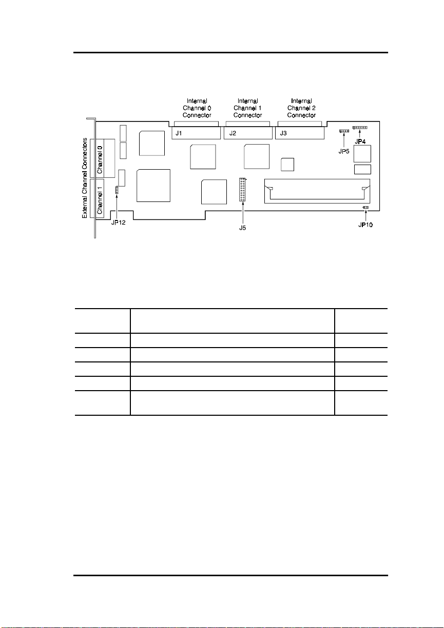
Installation
Connectors and Jumpers
Figure 3-1. DAC960PG Component Locations
Table 3-1. Jumper Blocks and Connectors
Component Description Default
Setting
JP4 Connector for harness to front panel LEDs (optional) -
JP5 Not used JP10 Select manufacturing diagnostics - Do Not Install Jumper Off
JP12 Jumper pins 1&2 for +5V RP - Leave at Default Pins 1&2
J5 Battery Backup Connector - If Battery Backup is not
installed, a loopback plug must be installed.
Loopback
Installed
Manual No. 771971 3-7
Page 56
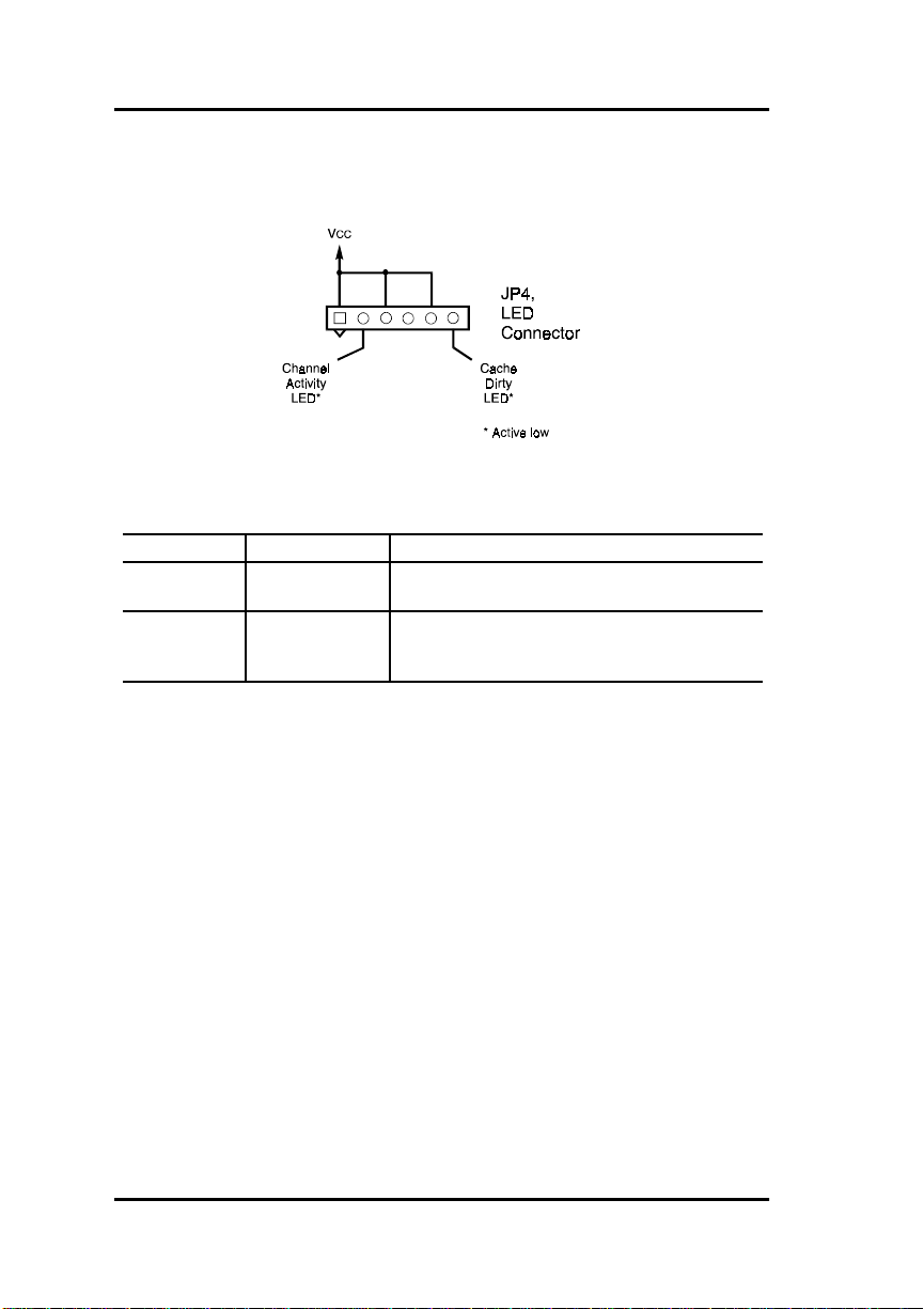
Connectors and Jumpers
External LED Connector
Figure 3-2. Pinout of Connector J4
Table 3-2. Status LED Indicators (from JP4)
Connector Indicator Meaning if ON
JP4, Pin 2 SCSI Activity One or more of the SCSI channels on the
JP4, Pin 6 Cache Dirty
(Write Pending)
controller is transmitting or receiving data.
The cache memory on the DAC960PG
contains data that is more current than the data
on the hard drive(s).
WARNING
,
DATA WILL BE LOST if the system either loses
power or is reset while the Cache Dirty LED is ON
(indicating the cache contains data not yet written
to the disk). To prevent data loss, install the
optional intelligent cache battery backup module
(IBBU).
3-8 DAC960PG Installation Guide
Page 57

Installation
SCSI Termination
Terminating a SCSI chain is accomplished either by adding a terminator to
the each end of the SCSI bus, or by terminating the devices closest to each of
the two ends of the SCSI bus.
Note
☛
The use of an external terminal at the end of the SCSI
bus away from the DAC960PG is preferred to
terminating the SCSI device at that end, as this allows
devices to be added to or removed from the SCSI bus
without having to add or remove termination.
The DAC960PG controller has on board ALT-2 type SCSI ter minators on all
drive channels. The on board termination logic will detect the presence of a
SCSI bus connected to the external connector and the internal connector of
each channel, and will enable or disable the on board termination as
required.
Terminating Internal Disk Arrays
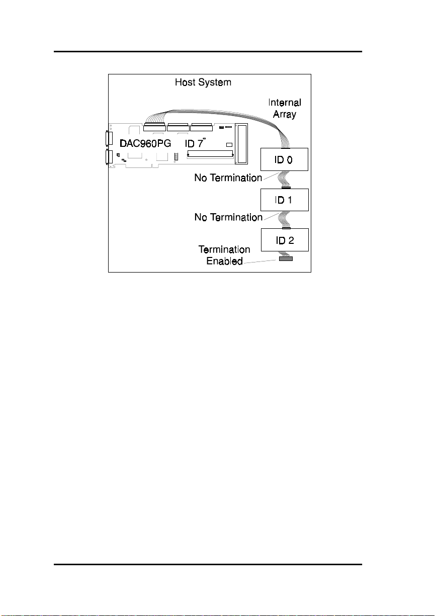
If the all the SCSI devices on a channel are connected to the internal
connector of a channel, the end of the SCSI bus farthest from the controller
must have a terminator installed.
The DAC960PG will automatically
the SCSI bus.
m
Caution
The internal connector of the DAC960PG must only
be connected to the end of a SCSI bus, not anywhere
in between the ends, or proper termination cannot be
ensured.
Manual No. 771971 3-9
on board terminat ion at its end of
enable
Page 58
SCSI Termination
Figure 3-3. Internal Disk Array, Single-ended SCSI Termination
3-10 DAC960PG Installation Guide
Page 59
Installation
Terminating External Disk Arrays
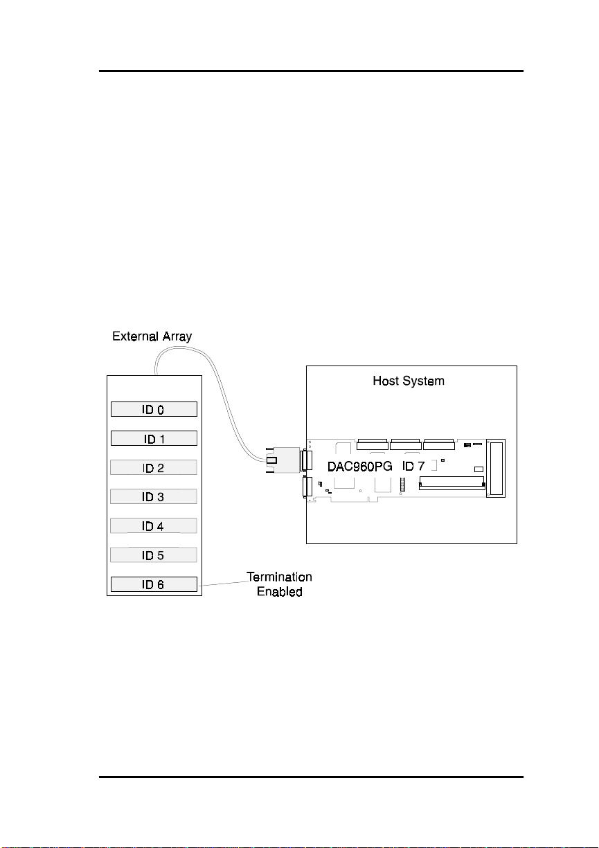
If the all the SCSI devices on a channel are connected to the external
connector of a channel, the end of the SCSI bus farthest from the controller
must have a terminator installed.
The DAC960PG will automatically
the SCSI bus.
m
Caution
The external connector of the DAC960PG must only
be connected to the end of a SCSI bus, not anywhere
in between the ends, or proper termination cannot be
ensured.
on board terminat ion at its end of
enable
Figure 3-4. External Disk Array, Single-ended SCSI Termination
Manual No. 771971 3-11
Page 60
SCSI Termination
Terminating Combined Internal and External Disk Arrays
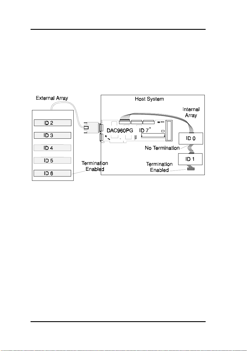
If some SCSI devices are connected to the internal connector of a channel,
and some SCSI devices are connected to the external connector of the same
channel, the two ends of the SCSI bus f arthest fro m th e con troller mu st each
be terminated.
The DAC960PG will automatically
Figure 3-5. Combination External/Internal Disk Array, SCSI Termination
its on board SCSI termination.
disable
Selecting the Correct Terminator
Use ALT-2 type external SCSI terminators for operating a SCSI channel at
10M Bytes/second (or faster) synchronous transfer rates. Use ALT-1 type
external SCSI terminators, for operating a SCSI channel at 5M Bytes/second
synchronous or asynchronous transfer rate. The DACCF Configuration
Utility can be used to set the transfer rate and mode for each channel.
3-12 DAC960PG Installation Guide
Page 61

Installation
Configuring the SCSI Devices
SCSI disk drives and other devices that will be connected to the controller
will need a certain amount of preparation before they are installed. This may
include setting jumpers to control term ination power on the bus, drive spinup order, and parity protoco ls
Setting Device Termination Power
SCSI backplanes and cables connected to the DAC960PG should be
configured to apply SCSI terminator power. SCSI backplanes frequently
have this feature enabled. If not, SCSI disks can be configured to enable
terminator power, bu t be s ure to enabl e SCSI t ermi nation power on the d isks
only if termination power is not already supplied by the cabinet.
Refer to the documentation supplied with your SCSI cabinets and disk
drives.
The same rules also apply to ‘non di sk’ SCSI devices connected to any of the
DAC960PG SCSI channels.
Setting Drive Spin-up & Parity Jumpers
If all of the SCSI drives are connected to a single power supply, or if the
power supply cannot supply the power needed to spin-up all of the drive
motors simultaneously, then the controller should be configured to spin-up
the drives separately. By spinning up th e hard drives separately, the power
supply is not unnecessarily loaded by the large starting current required to
spin-up drives simultan eously. If drives are to be spun- up individuall y by the
controller, they may need to be shunted to spin-up on command, not at
power-on. See the specifications accompanying the SCSI drive for proper
jumper settings.
Also, the DAC960PG should be configured to spin-up the drives at regular
intervals by giving each drive a spin-up command. See the
Installation Guide and User Manual
spin-up options. Tape and CD-ROM spin-up options should be left at the
factory defaults.
The drive parity jumpers, if any, should be set to always
SCSI data coming in, and to
Manual No. 771971 3-13
send
for more information on the disk drive
parity with the data sent to the controller.
DACCF Utilities
parity on the
enable
Page 62

SCSI Cabling
SCSI Cabling
Three things must be kept in mind while cabling the controller to the drives:
• SCSI Bus Termination
• System Performance
• SCSI Cable Length.
Every SCSI channel needs to be properly terminated with an appropriate
SCSI terminator, as previously mentioned. In general, no drives should be
terminated, and all drives must be shunted to supply TERMPWR on the
SCSI bus.
Note
☛
When connecting a Narrow SCSI (8-bit) cable to any
DAC960PG channel, the controller must be at one
end of the bus and
for that channel.
To get the best performance from the controller, the SCSI drives should be
equally distributed across the SCSI channels, and the controller’s data
transfer rate should be set to the optimum rate for the drives being used.
Termination Enabled
must be set
Note
☛
The SCSI transfer rate can be individually selected for
each of the three channels on the DAC960PG. For
more information, refer to the
Installation Guide and User Manual
Figure 3-6 shows disk drives connected to two channels and grouped across
channels. The drive not included in a group can be a standby drive available
to either group. The tape drive is connected to a separate channel from the
disk drives.
Figure 3-6. Drive Grouping Example
3-14 DAC960PG Installation Guide
DACCF Utilities
.
Page 63

Installation
Cable Lengths
Generally speaking, as SCSI data transfer rates increase, maximum
allowable cable lengths decrease. Transfer rates of 5 MB/sec for 8-bit SCSI
or 10 MB/sec for 16-bit SCSI will normally allow a 6 meter (20 foot)
maximum cable length on a channel. Transfer rates of 40 MB/sec for 16-bit
Ultra SCSI permit a maximum cable length of only 1.5 meters, if more than
4 devices are on the channel.
Note
☛
Strict adherence to guidelines for over-all cable length
is necessary when connecting Ultra-SCSI drives that
will operate at the higher data transfer rates of the
Fast-20 standard (refer to ANSI STD X3.131 for
information on SCSI cabling requirements).
Table 3-3. Supported SCSI Formats and Cable Lengths
SCSI Type Clock Rate Data Rate Connector Cable Length
Ultra-SCSI
(16-bit)
Ultra-SCSI
(8-bit)
Wide SCSI-2
(16-bit)
Narrow SCSI-2
(8-bit)
SCSI-1 (8-bit) 5 Mhz 5 MB/sec 50-pin* 6 m (20 ft)
* 50-pin to 68-pin adapter required
† 3 meters with up to 4 SCSI devices or 1.5 meters with more than 4 SCSI devices
20 Mhz 40MB/sec 68-pin 3m (10 ft)†
20 Mhz 20MB/sec 68-pin or
10 Mhz
5 Mhz
10 Mhz
5 Mhz
20 MB/sec
10 MB/sec
10 MB/sec
5 MB/sec
50-pin*
68-pin 3 m (10 ft)
68-pin or
50-pin*
3m (10 ft)†
6 m (20 ft)
3 m (10 ft)
6 m (20 ft)
Manual No. 771971 3-15
Page 64
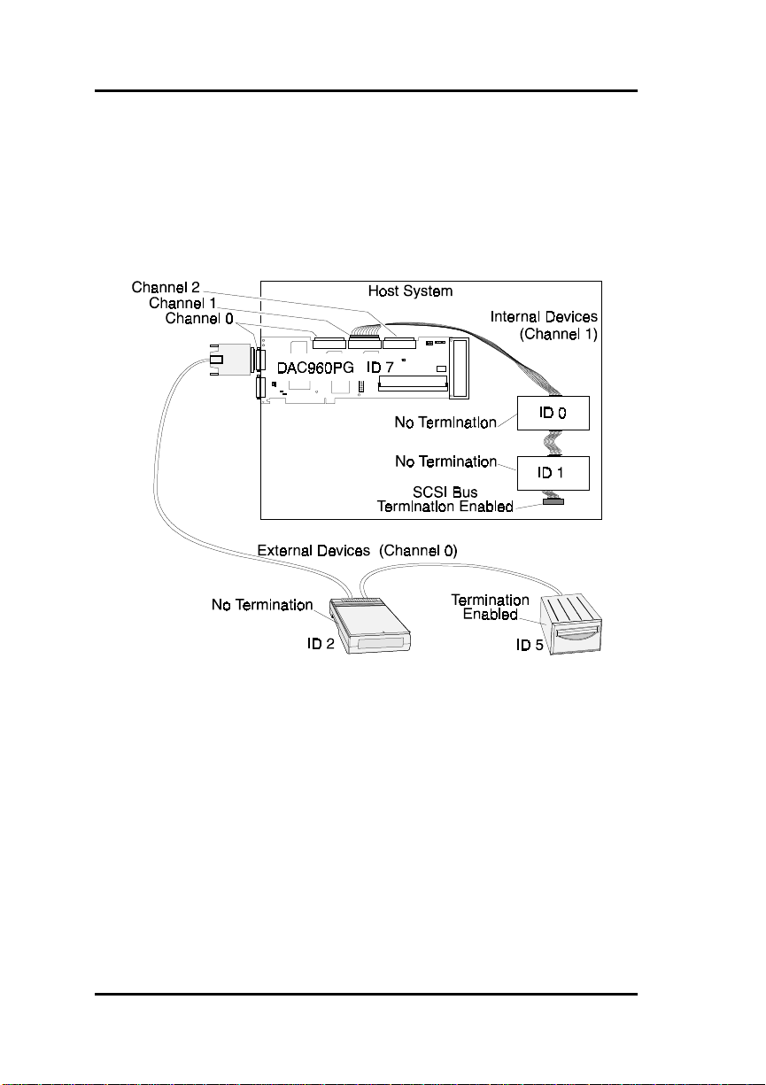
SCSI Cabling
Connecting Non-Disk Devices
Non-disk SCSI devices, such as a tape drives or CD-ROM drives, will need
to have their own unique SCSI ID, regardless of the channel of the
DAC960PG to which they are connected. For instance, the general rule for
UNIX systems is to set the tape to SCSI ID 2, the CD-ROM to SCSI ID 5,
with both devices connected to channel 0.
Figure 3-7. Connecting Non-disk Devices
m
Caution
Connecting non-disk devices to DAC960PG drive
channels can result in disk drive performance loss.
While the DAC960PG does support non-disk devices, their use on SCSI
channels containing disk drives is not recommended. The affect these
devices have is to slow the controller’s performance on that channel
to the I/O transfer rate of the tape or CD-ROM drive, instead of the much
faster rates supported by most hard drives.
3-16 DAC960PG Installation Guide
Page 65

Installation
You can work around this problem by connecting the non-disk devices to
one channel of the DAC960PG, while connecting the har d drives to the other
channels. However, most people do not wish to give up one channel of a
high-performance, caching disk arr ay contro ller for this p urpose. Th e simple
solution is to use a dedicated Bus Logic SCSI host bus adapter for
connecting all non-disk devices.
For more information on configuring the DAC960PG, be sure to read the
DACCF Utilities Installation Gu ide and User Manual
Configuration Strategies
.
, Chapter 2,
Using a UPS
If write-back caching is enabled, installation of an uninterruptable power
supply (UPS) is highly recommended on systems that use a DAC960P G not
equipped with the battery backup option. Loss of power to the contro ller
during system activity can result in loss of data; because data in the
controller cache that is waiting to be written to disk will be lost unless the
controller has the optional cache battery backup installed.
Installation of a UPS may eliminate this situation co mpletely. If properly
installed, the UPS will supply uninterrupted power to the host system and its
drives and allow the operating system to properly shut down before power is
removed from the system.
Manual No. 771971 3-17
Page 66

Cache Battery Backup Option
Cache Battery Backup Option
The optional cache battery backup provides temporary protection for
unwritten data in the controller’s cache memory in the event of a system
reset or power loss. Data maintained in the cache will be written to disk after
power is restored.
The optional cache battery backup module is available for the DAC960PG to
provide, in the event of a power failure, battery backup to the SIMM mo dule
installed on the controller.
Battery Backup Module Connector
Connector J5 is available for the optional cache battery backup module. If
the optional cache battery backup module is not installed, the loop-back plug
must be present on connector J5 for proper controller operation.
,
WARNING
Be careful to observe proper orientation when
inserting a battery backup module or the loopback plug in connector J5. Check to make sure
that Pin 1 on the module corresponds to Pin 1 on
connector J5, and that all pins are mating properly
before full insertion. Improper insertion may
result in physical damage to the controller.
3-18 DAC960PG Installation Guide
Page 67

Chapter 4
Start-up Sequences
Introduction
This chapter describes the DAC960PG start-up procedures and messages
produced by the BIOS during start-up or re-boot. This chapter also explains
three BIOS options to be considered: BIOS enable/disable, CD-ROM boot
enable/disable, and a 2 or 8 Gigabyte Disk Drive Geometry settin g.
The DAC960PG BIOS provides a single threaded interface to access up to
eight logical units (system drives) on each controller.
The Firmware 4.x BIOS presents physical drives to the host as large disk
drives with either 2 MB per cylinder or with 8 MB per cylinder. An
allowable number of up to 1024 cylinders allows a physical drive of up to
8GB to be accessed through th e BIOS. An operating system specific driver is
required to access data beyond this limit.
Refer to the documentation for the DAC960 Software Kit for more
information on installing and using the various network operating system
drivers with the DAC960PG.
Instructions on using the DOS driver and creating a DOS-bootable disk are
located in the DACCF Configu r ation & Utilities diskette DOS subdirectory
in the file
README.TXT
.
System Power-Up Sequence
If the SCSI drives are powered up separately from the system, you should
always power up the SCSI drives before the host system. The drives an d the
host system can power up simultaneously, as they would when there is a
common power switch for both.
BIOS Start-up Sequence
When invoked during power up, the BIOS will display a sign-on message
with its version number and date. The sign-on message looks similar to the
following:
DAC960 BIOS Version n.nn--
Manual No. 771971 4-1
Page 68

Setting BIOS Options
This will be followed by:
Spinning up drives....
DAC960PG Firmware Version 4.nn-n-n
DAC960PG Memory = xMbytes (DRAM)
Press Alt-M for BIOS options
At this point, the user has the option of holding down the
key and
Alt
pressing the M key to go into the BIOS options menu (see the following
subsection
Setting BIOS Options
). If the user does nothing, the sequence
continues.
Next, the BIOS tries to locate the DAC960PG. Once the DAC960PG
controller is located, it determines if the controller firmware is operational.
Setting BIOS Options
There are three DAC960PG BIOS options that need to be considered and
possibly change d during install ation of the DAC960PG. This is usually a
one-time requirement. The BIOS options are:
• BIOS enabled/disabled
• CD-ROM boot disabled/enabled
• 8/2 GB drives enabled
Invoking the BIOS Options Menu
When starting the system with a DAC960PG installed, the start-up sequence
displays a series of messages that confirm or deny successful SCSI device
installation. These messages are followed by the next prompt:
Press Alt-M for BIOS options
There will be a pause for approximately two seconds in which this option
can be invoked. To examine or change the BIOS options, press and hold the
key and then press M.
Alt
The following menu will appear:
4-2 DAC960PG Installation Guide
Page 69
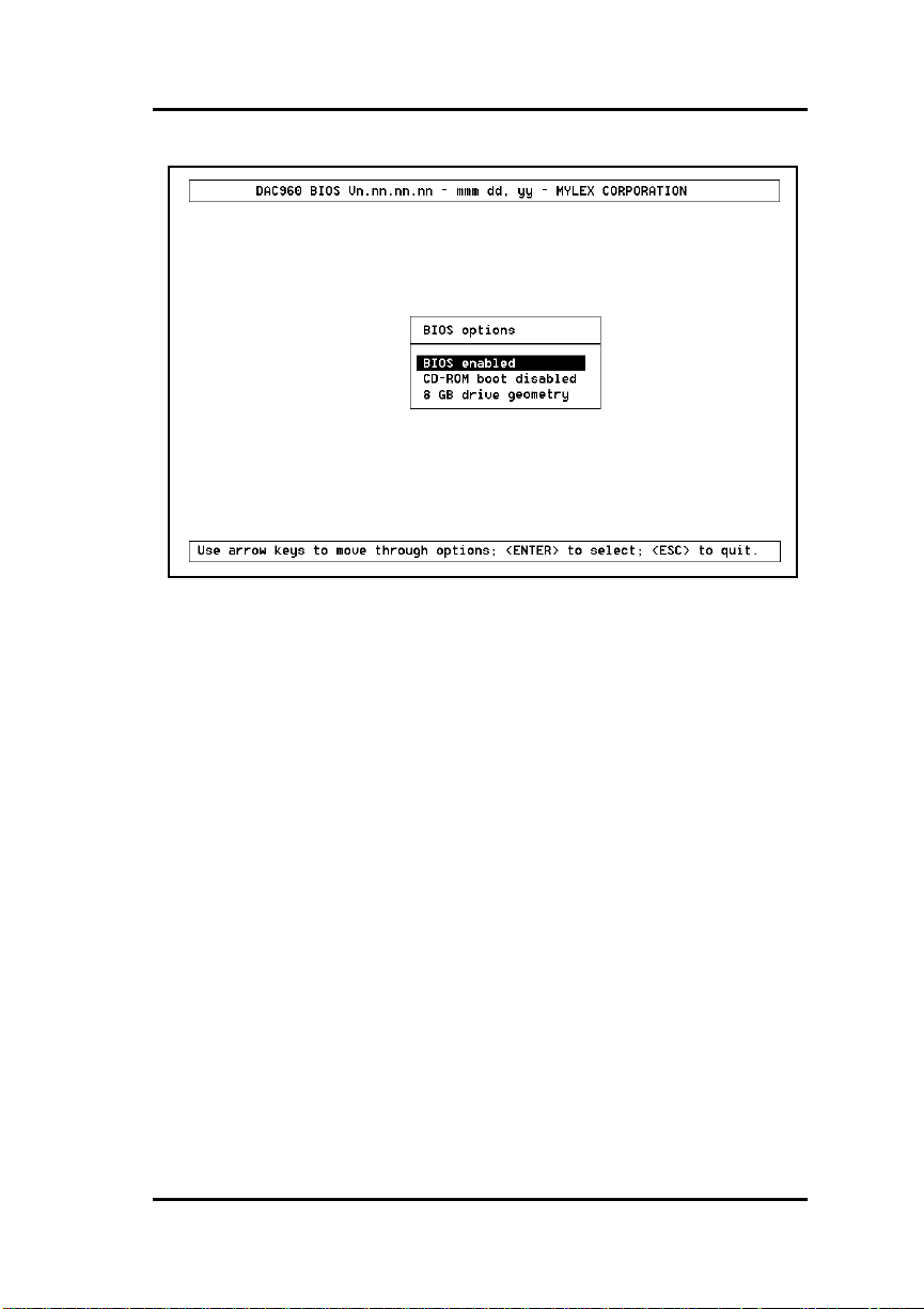
Start-up Sequences
Figure 4-1. BIOS options Menu
Use the up and down arr ow keys to highligh t the BIOS optio ns to be toggled.
While a desired option is highlighted, press the
option.
key to toggle the
Enter
Note
☛
If the BIOS is disabled, it will not be possible to
change the other options.
If the boot driv e is on a DAC960PG, t hen drive g eometry changes should not
be attempted unless the boot drive is going to be reformatted. The option to
change the disk drive geometry between 8 gigabytes and 2 gigabytes stops
and generates a warning about the potential of data loss before the change
proceeds.
Manual No. 771971 4-3
Page 70
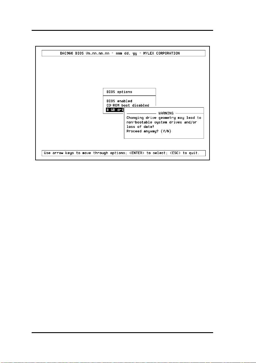
Setting BIOS Options
Figure 4-2. BIOS Options Menu when Drive Geometry Option is Selected
Press the
key to exit the BIOS options menu. The following message
Esc
will be displayed:
4-4 DAC960PG Installation Guide
Page 71
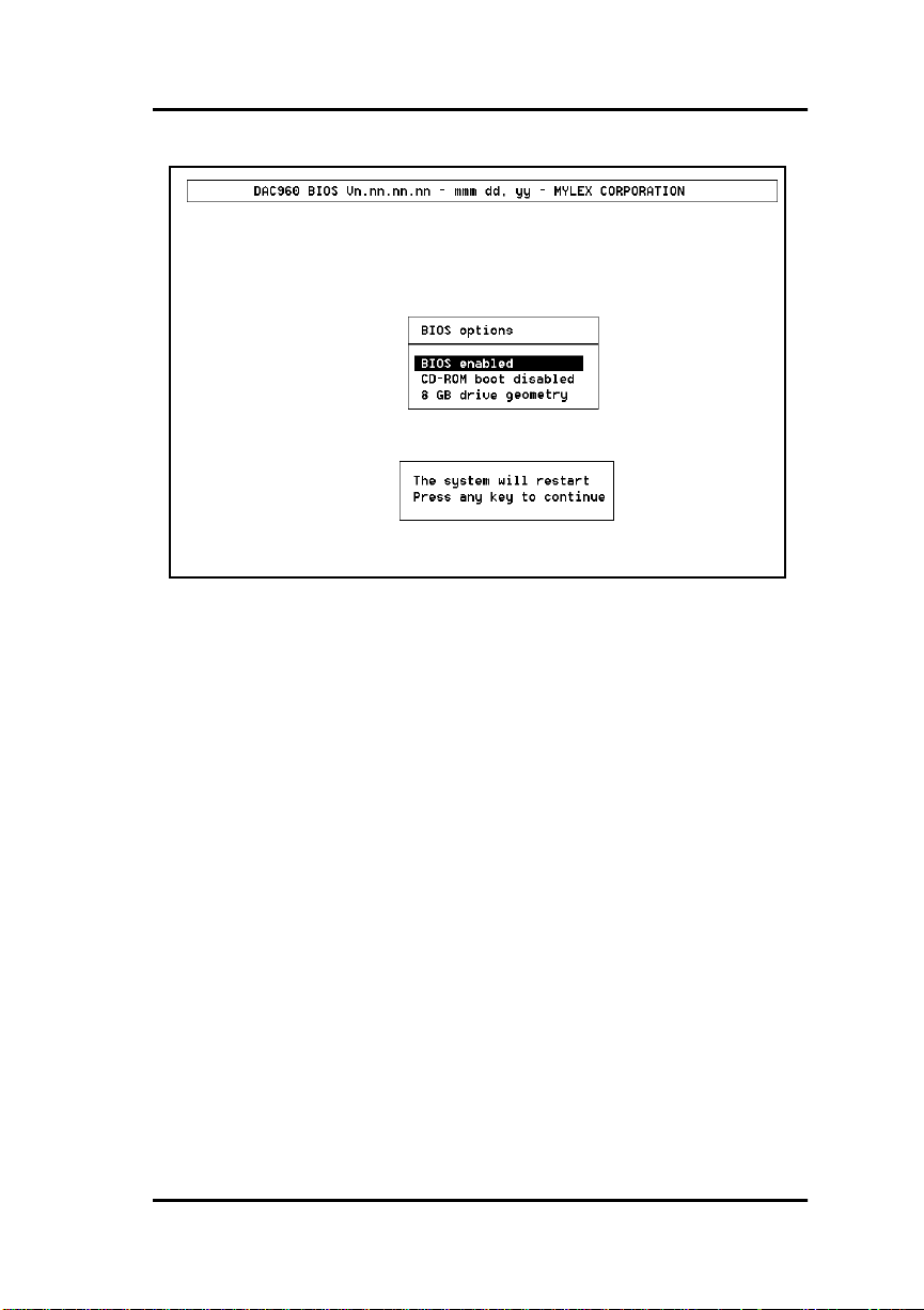
Start-up Sequences
Figure 4-3. BIOS Options Menu Prior to Exit
BIOS Enable or Disable
The default for this option is for the BIOS to be enabled. Disabl ing the
BIOS prevents the DAC960PG from being the boot controller. While the
BIOS is disabled, it will not be possible to make chan ges to the other BIOS
options.
CD-ROM Boot Disable or Enable
The default for this option is for the CD-ROM boot to be disabled (e.g., the
system will boot from a hard drive. If a bootable CD is installed in the CDROM drive, the system can boot from the CD if this option is set to enabled.
If the CD-ROM boot option is enabled, the CD-ROM will take priority over
the disk drives. For example, under MS-D OS, the disk drive that is normally
Drive C: will become Drive D. All subsequent drive IDs will similarly be
moved down.
Manual No. 771971 4-5
Page 72

Error Messages
Enable 8 GByte or 2 GByte Drives
This option can be toggled between 8 gigabyte and 2 GB drive geometries.
The default is 2 GB. This setting affects how the BIOS reads the disk drives.
The drive geometry must be set and then the drive must be formatted (or
reformatted).
The DAC960PG ships with the default BIOS geometry set to 2 GB . This
means that the BIOS will only be able to see the firsst 2 gigabytes of any
drive that has been configured on the DAC960PG. This is adequate in most
applications since BIOS is only used to boot the operating system.
However, it does mean the operating system must be installed somewhere in
the first 2 GB of the configured drive’s capacity. If for some reason this is
not adequate, the BIOS geometry can be changed to 8 GB. This will allow
the BIOS to see the first 8 GB of capacity.
m
Caution
If you have already configured your array and have
stored data, you should
Changing this setting after data has been stored will
have an effect similar to changing your stripe size. It
will make your stored data unreadable.
change this setting.
not
Error Messages
Start-up Error Messages
The BIOS also looks for any initialization message that may be posted by the
firmware during the start-up sequence. If it finds a message, it displays one
of the following errors on the screen and aborts the installation process.
DAC960PG fatal error--memory test failed
DAC960PG fatal error--command interface test failed
DAC960PG hardware error--run diagnostics to pinpoint error
DAC960PG firmware checksum error--reload firmware
4-6 DAC960PG Installation Guide
Page 73

Start-up Sequences
Drive Check Error Messages
If the firmware finds a valid DAC960PG con figuration, but it doesn't match
the SCSI drives currently installed, one or more of the following messages
will be displayed:
Unidentified device found at channel x....
Device identified for chn x, tgt y found at chn x', tgt y'
SCSI device at chn x, tgt y not responding
If any of the above messages are displayed, the firmware will not proceed
any further in the initialization process, except to find other mismatches.
Then, the BIOS will print out the following:
DAC960PG Configuration Checksum error--run configuration
utility
Mismatch between NVRAM and Flash EEPROM configuration
At the next stage the following message may appear:
Recovery from mirror race in progress
This will be displayed if the firmware detects that during the last power
cycle, the system was turned off abruptly, leaving some incomplete write
operations.
The following messages may also appear:
Adapter cannot recover from mirror race!
Some system drives are inconsistent!
During the initialization, if the firmware fails to respond to the BIOS inquiry
within two minutes, the following me ssage will be displayed:
DAC960PG not responding--no drives installed.
The BIOS then inquires the firmware for its version number and oth er
information, and prints out the following message:
DAC960PG firmware version x.xx
One or more of the following messages will be displayed if the firmware
reports the following conditions:
Warning: X system drives are offline
Warning: X system drives are critical
Warning: The following SCSI devices are dead--chn
Manual No. 771971 4-7
Page 74

Error Messages
x, tgt y...
No system drives found: None installed
X system drives installed
The BIOS repeats the same process for additional DAC960P G controllers
present in the system. Then it proceeds to boot, if possible, from the first
system drive on the first DAC960PG controller.
4-8 DAC960PG Installation Guide
Page 75

Start-up Sequences
Aborted Installation
With Firmware 4.x, the installation aborted message is displayed when the
BIOS finds that the configuration of the disk drives, as stored in the
NVRAM and configuration on disk, is different from what it sees at boot
time. When this happens, (and a brand new installation is not being
attempted) the cause is often a faulty cable or drive, or a loose connection.
Check all of the connectors, cables, drives, and try to boot. If the error
persists, it most likely indicates a genuine failure and needs to be corrected.
To correct it, boot DOS and run the configuration utility. For more
information, refer to the
Manual
.
DACCF Utilities Installation Guide and User
NVRAM Error
With Firmware 4.x, if the BIOS displays a mismatch between the NVRAM
and the COD, no drives will be installed. Normally this error will not be
displayed. If it is, boot DOS and run the configuration utility to recover
from the error. For more information, refer to the
Installation Guide and User Manual
.
DACCF Utilities
System Reboot or Power Down
Status messages may also be available from LED indicators connected to the
DAC960PG. The ‘Write Pending’ indicator is especially important when
preparing to power-down the system.
The DAC960PG is a caching controller with up to 12 8MB of cache me mory,
data may still be in the cache, waiting to be written to the disk drives, when
the system reports that a write command was completed. It is
important
or powering down the system, or you may lose data. It is always a good idea
to wait for 15 seconds before any resetting/rebooting of the system.
If using the 'Write P e nd ing' LED indicator, wait for 3 second s aft er the LED
has gone off before resetting or rebooting the system (the optional cache
battery backup may also be used to prevent data loss).
Manual No. 771971 4-9
to make sure that all data is written to the disk before rebooting
very
Page 76

System Reboot or Power Down
4-10 DAC960PG Installation Guide
Page 77

Appendix A
Enclosure Management
Introduction
The DAC960PG supports enclosure management protocols. This feature
allows the host to monitor drive enclosures and detect certain faults or
operating environment conditions. The host can make a decision to shut
down the system or issue a warning based on the type of fault detected.
The DAC960PG supports the industry standard enclosure management
protocol
SCSI Accessed Fault-Tolerant Enclosures
SAF-TE
The SAF-TE protocol follows a specification jointly worked out by Conner
Peripherals and Intel Corporation. Enclosures that are compliant with this
protocol are known as SCSI Access ed F ault -To ler a nt En clo su res (SAF-T E).
The protocol is compatible with standard SCSI buses and cabling.
The SAFE-TE interface standard’s objective is to provide a non-proprietary
means of allowing third-party disks and controllers to be automatically
integrated with peripheral enclosures that support:
(SAF-TE).
• Status Signals (LEDs, audible alarms, LCDs, etc.)
• Hot swapping of drives
• Monitoring of fans, power supplies, and enclosure temperature
SCSI is the underlying transport mechanism for communicating enclosure
information. All standard SCSI host adapters will work. There is no need to
consider reserved signals or special cabling.
Manual No. 771971 A-1
Page 78

SAF-TE
A-2 DAC960PG Installation Guide
Page 79
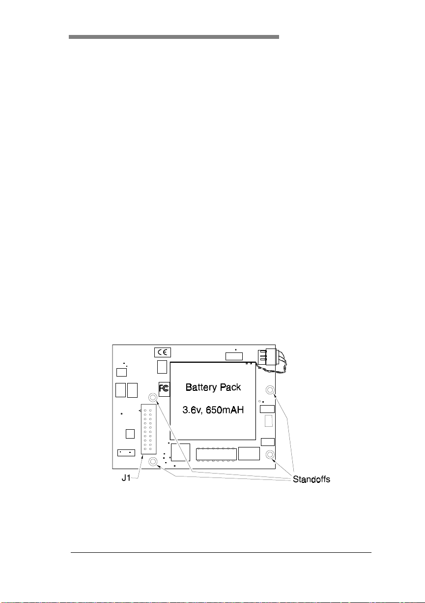
Appendix B
Intelligent Battery Backup Unit
Product Description
The Intelligent Battery Backup Unit (IBBU) is an add - on module that
provides power to the DAC960PG PCI to Ultra-SCSI RAID Controller
cache memory in the event of a power failure. The battery backup module
monitors the write back cache on the DAC960PG, and provides power to the
cache if it contains data not yet written to the drives when power is lost.
The DAC960PG controller, with the IBBU installed, together occupy only
one PCI slot on the host backplane.
Features
Some of the new features of the IBBU include:
• Gas gauge circuit for battery charge monitoring
• Quick charge to replenish a drained battery
• Support for low-power EDO ECC RAM modules
IBBU Components
Figure B-1. IBBU Components
Manual No. 771971 B-1
Page 80

IBBU Specifications
IBBU Specifications
Electrical
On-board Battery
Electrical Properties
• 3 NiCd 1.2 V, 650 mAH cells, connected in series for a total of 3 .6V
at 650mAH
Physical Description
• Nominal pack size (in inches): 1.89(L) X 2.01(W) X 0.33 (H)
Battery Charge Life
Depends upon memory in use
External Battery
Not supported
Module Dimensions
Length: 3.75 inches
Width: 2.875 inches
Environmental
Temperature Operating: 0ºC to +40ºC
(+32ºF to 104ºF)
Storage: -40ºC to +60ºC
(-40ºF to +140ºF)
Humidity Operating: 45% to 85%
relative humidity
Non-operating: 45% to 85%
relative humidity
B-2 DAC960PG Installation Guide
Page 81

Functional Description
General Operational Description
The IBBU consists of the following five blocks
Intelligent Battery Backup Unit
1. Electronic switches that connect between V
converter output to V
(actual voltage being applied).
BB
2. Power fail (PF) detector that detects the presence or absence of V
and the DC-DC
CC
CC
.
3. Charger and battery block
4. DC-DC converter to convert 3.6 vdc from the battery to 5 vdc for
backup power.
5. Refresh generator to generate Column Address Strobe (CAS
Address Strobe (RAS
) signals for refresh cycles.
) and Row
Whenever the system is running, the IBBU is standing by, monitoring the
voltage level of VCC. In the event of a power failure, the VCC vo ltage level
will begin to drop. When the IBBU detects this voltage drop, it checks the
status of the disk cache. If the cache is empty, the IBBU does nothing.
If the cache contains data during a power failure, it means that there was not
enough time for the cache contents to be written to the disk array. If this is
the case, the data in the cache needs to be preserved. The IBBU immediately
disconnects VCC and connects its own power output to the cache. At the
same time the memory control unit’s RAS
from the cache and are replaced by RAS
and CAS signals are disconnected
and CAS signals of its own.
The IBBU will maintain cache data integrity until the power is restored.
When power is restored and the system finishes the bootstrap process, the
cache contents will be written to the disk array. The cache contents will then
be flushed from the cache.
Status Indication
The status of the battery can be checked with the gas gauge feature that can
be accessed in GAM (version 2.1x or greater is needed). The gas gauge
appears on the screen as two meters— a battery power meter and a charge
level meter— each calibrated from 0 to 100.
Manual No. 771971 B-3
Page 82

Functional Description
The battery power meter indicates the battery capacity in hours. It will
indicate a charge duration of up to 100 hours. The firmware will detect the
Mylex supplied SIMM and assig n a value based up on the charge le vel of the
battery and the power consumption rate of the SIMM.
m
Caution
Do not use SIMMs which are not supplied by Mylex
without first contacting Mylex T echnical Suppor t .
The charge level meter displays the charge state of the battery expressed in
percent. A fully charged battery will cause the charge level meter to indicate
100%.
When the meter on the right indicates the battery is fully charged, the meter
on the left will indicate the maximum time in hours that the b a ttery can be
expected to maintain cache data integrity. This value will vary depending
upon which Mylex supplied SIMM is being used (see Tabe 4-1).
Note
☛
When the charge level is 100%, the
and
hours
below the left dial) will be equal.
maximum number of hours
current number of
(printed out
Battery and Charge Circuit
On-board Battery
The on-board battery is rated at 3.6 v with a capacity of 650 mAH. The
IBBU has a DC-DC converter that co nver ts the 3 .6 v fro m th e battery to 5 v,
which is the nominal voltage needed to replace V
occur.
Battery Charger
Battery charging and conditioning are automatically handled by the IBBU.
No manual preconditioning needs to be performed by the user.
The battery charger uses the input of the +12 vdc from the PCI bus to ch arge
the battery. Internal current-limiting circuitry along with the IBBU ’s gas
gauge circuitry are used to control the battery’s rate of charge for maximum
efficiency. If the battery capacity falls below a predetermined level (which
is likely to happen during a power failure), the battery charger goes into a
quick charge mode. If the battery is fully charged, the charger goes into a
trickle charge mode.
B-4 DAC960PG Installation Guide
if a power failure should
CC
Page 83
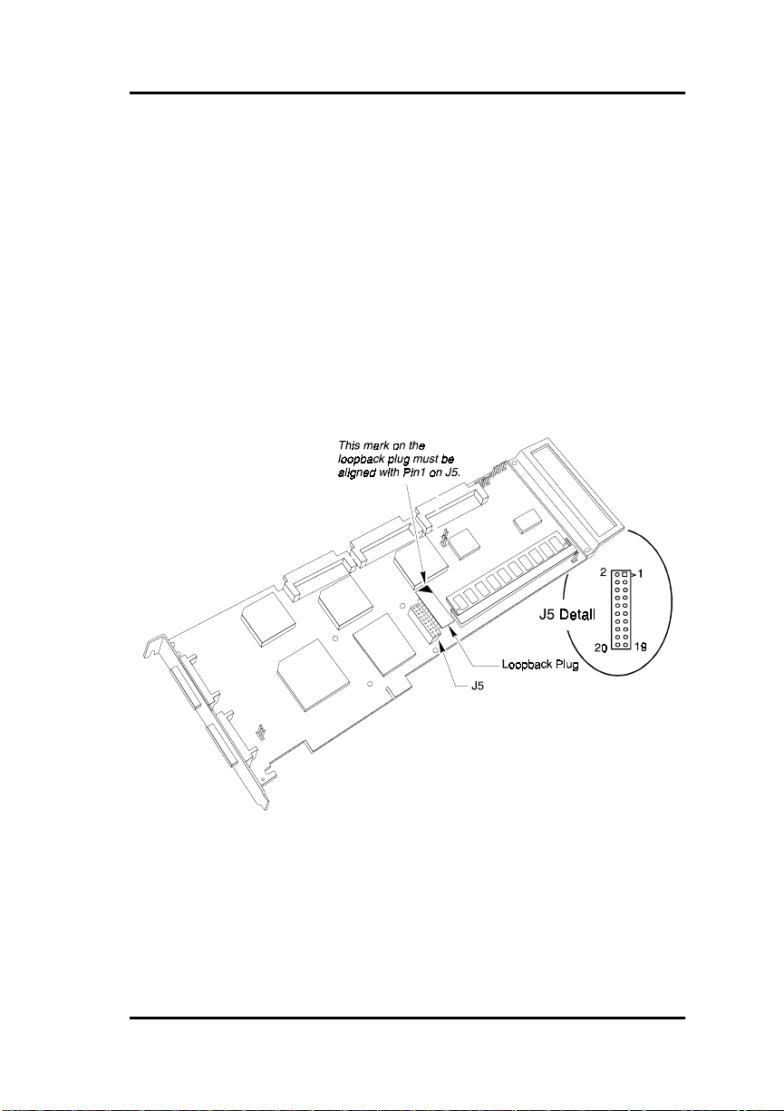
Intelligent Battery Backup Unit
Installation
Mechanical Installation Procedure
Tools Needed
The only tool needed for the installation is a small, flat-blade screwdriver
Procedure
1. If the DAC960PG is not already removed from the system, power the
system down and then remove the DAC960PG.
2. Remove the loopback plug from J5 on the DAC960PG. Keep the
loopback plug in a safe place, in case the IBBU needs to be removed at
a later time.
Figure B-2. Removing the Loopback Plug from J5 on the DAC960PG
Manual No. 771971 B-5
Page 84
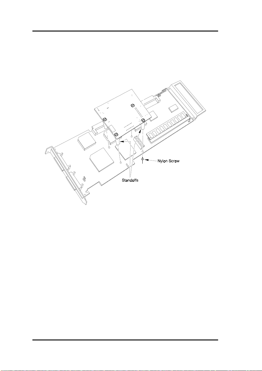
Installation
3. Remove the protective pin cover and peel-off label from J1 on the
IBBU.
4. Leaving the 4 standoffs attached to the IBBU, remove a nylon screw
from the free end of each nylon standoff.
Figure B-3. Installing the IBBU onto the DAC960PG
5. Install the IBBU so that J1 on the IBBU connects to J5 on the
DAC960PG. P i n 1 on the IBBU’s J1 must connec t to hole 1 on the
DAC960PG’s J5. The mounting holes on the IBBU will line u p with
the mounting holes on the DAC960 PG if th e connecto rs are plugged in
correctly.
6. Be sure the 4 standoffs line up with the 4 holes in the DAC960P G .
Place a nylon screw through a hole from the back of the DAC960PG
into a standoff, and turn the screw to the right un til it is snug (not too
tight). Repeat this step with the remaining 3 standoff screws.
B-6 DAC960PG Installation Guide
Page 85

Intelligent Battery Backup Unit
Operation
Battery Conditioning Prior to Use
Battery conditioning is automati c. There are no manu al procedures for
battery conditioning or preconditioning to be performed by the user.
Set-up – Enabling the Write-Back Cache
The write-back cache is enabled by toggling the write-back/write-through
mode switch. The write-back/write-through mode switch is accessed in
either DACCF or in GAM. Refer to the
and User Manual
Manual
for instructions on how to examine and change the mode switch.
or the
Global Array Manager Inst allati on Gui de and User
Maintenance
No maintenance is required. It is recommended that the IBBU charge level
be periodically checked using the Gas Gau ge function in GAM 2 .10 (see th e
Global Array Manager Installation Guide and User Manual
DACCF Utilities Installation Guide
).
Manual No. 771971 B-7
Page 86

Battery Backup Capacity
Battery Backup Capacity
Battery backup capacity is defined as the maximum duration of a power
failure for which data in the cache can be maintained by the battery. The
IBBU’s backup capacity varies with the memory configuration installed on
the DAC960PG. Battery backup capacity can be reasonably expected
according to Tabe 4-1
Table 4-1. IBBU Capacity vs. Cache Memory Configuration
Capacity Mem Type Battery Backup
4 MB EDO ECC RAM 50 hours
8 MB EDO ECC RAM 25 hours
16 MB EDO ECC RAM 35 hours
32 MB EDO ECC RAM 15 hours
64 MB EDO ECC RAM 25 hours
128 MB EDO ECC RAM 15 hours
Duration (Min)
Calculations for Battery Duration
The backup capacity of the battery (in hours) on the IBBU module is
calculated using the following formula:
Duration in hours = B / (I
Where:
B = battery capacity in mAh (= 600 for the battery on the IBBU)
= SIMM current in mA @ 5V
I
SIMM
This is derived from the average of I
RAS @ 130ns / 16
battery voltage (= 3.6V) times the DC-DC effieicncy coefficient (= .85).
or:
=(I
I
SIMM
I
P
Therefore the Duration in hours = 600 / (I
x .008125 x 5) / (3.6 x .85)
CBR
=(I
x .040625) / 3.06
CBR
= IB BU current (2mA max) @ 3.6V
µs (= .008125) times SIMM voltage (= 5V), all divided by
SIMM
+ IP)
, or SIMM current during CAS before
CBR
+ 2)
SIMM
B-8 DAC960PG Installation Guide
Page 87

Intelligent Battery Backup Unit
Removing the Battery Backup Module
The battery backup module will need to be removed for one of the following
reasons:
1. The NiCd battery will no longer accept a charge properly (NiCd battery
life expectancy is approximately 5 years).
2. The cache memory needs to be removed from the DAC960PG for
replacement or upgrade.
,
WARNING
Do not attempt to install, remove, or change a
cache SIMM on the DAC960PG with the IBBU
installed. Serious damage to the SIMM and/or the
battery backup unit will occur if this precaution is
not followed.
Manual No. 771971 B-9
Page 88
Battery Backup Capacity
m
Caution
If you plan to operate your DAC960PG without the
IBBU, be sure to reinstall the loopback plug (see the
“Mechanical Installation Procedure” section and
Figure B-2).
Recycling the Battery
The on-board battery that comes with the IBBU has the logo of the
Rechargeable Battery Recycling Corporation (RBRC) stamped on it. The
recycling fees have been prepaid on this battery pack.
m
Caution
Do not dispose of a rechargeable battery with regular
trash in a landfill. Rechargeable batteries contain
toxic chemicals and metals that are harmful to the
environment. Improperly disposing of rechargeable
batteries is also illegal.
Figure B-4. RBRC Logo
The RBRC logo on a battery is a verification that recycling fees have been
prepaid to the RBRC and such a battery can be r ecycled at no ad ditional cost
to the user. The RBRC is a non-profit corporation that promotes the
recycling of rechargeable batteries, including nickel-cadmium batteries.
B-10 DAC960PG Installation Guide
Page 89

Intelligent Battery Backup Unit
Information on the RBRC program and the locations of particip ating
recycling centers can be obtained by telephoning 1–800–8–BATTERY (in
the USA), and following the recorded instructions. The infor mation obtained
from this telephone number is updated frequently, since the RBRC program
is growing, and new recycling locations are being added regularly.
Manual No. 771971 B-11
Page 90

Battery Backup Capacity
B-12 DAC960PG Installation Guide
Page 91

Glossary
Battery Backup Unit
See “Intelligent Battery Backup Unit.”
Cache
Controller memory used to speed up data transfer to and from a disk.
Cache Flush
Refers to an operation where all unwritten blocks in a Write-Back Cache are
written to the target disk. This operation is necessary before powering down
the system.
Cache Line Size
See “Segment Size.”
Channel
Refers to one SCSI bus on a DAC960 Series controller. Each DAC960PG
provides at least one channel, or additional channels with optional upgrades.
Consistency Check
Refers to a process where the integrity of redundant data is verified. For
example, a consistency check of a mirrored drive will make sure that the data
on both drives of the mirrored pair is exactly the same. Fo r RAID Level 5
redundancy, a consistency “connect” is a function that allows a target SCSI
device (typically a disk drive that received a request to perform a relatively
long I/O operation) to release the SCSI bus so that the controller can send
commands to other devices. When the operation is complete and the SCSI
bus is needed by the disconnected target again, it is “reconnected.”
Manual No. 771971 Glossary-1
Page 92

Glossary
Disk Failure Detection
The controller automatically detects SCSI disk failures. A m onitoring
process running on the controller checks, among other things, elapsed time
on all commands issued to disks. A time-out causes the disk to be “reset”
and the command to be retried. If the command times out again, the disk
could be “killed” (taken “offline”) by the controller (its state changed to
“dead”). DAC960PG controllers also monitor SCSI bus parity errors and
other potential probl ems. Any dis k with too many errors will al so be ‘kil led’.
Disk Media Error Management
DAC960PG controllers transparently manage SCSI disk media errors. Disks
are programmed to repor t errors, even ECC-recov erable error s. If ECC EDO
RAM is installed, the controller will correct ECC errors.
When a disk reports a media error during a read, the co ntroller reads the data
from the mirror (RAID 1 or 0+1), o r computes the dat a from the oth er blocks
(RAID 3, RAID 5), and writes the data back to the disk that encountered the
error. If the write fails (media error on write), the controller issues a
“reassign” command to the disk, and then writes the data to a new location.
Since the problem has been resolved, no error is reported to the system.
When a disk reports a media error during a write, the controller issues a
“reassign” command to the disk, and writes the data out to a new location on
the disk.
Drive Groups (or Drive Packs)
A group of individual disk driv es (preferabl y identical) that are log ically tied
to each other and are addressed as a single unit. In some cases this may be
called a drive “pack” when referring to just the physical devices. Up to eight
(8) drives can be configured together as one drive group.
All the physical devices in a drive group should have the same size,
otherwise each of the disks in the group will effectively have the capacity of
the smallest member. The total size of the drive group will be the size of the
smallest disk in the group multiplied by the number of disk s in the group.
For example, if you have 4 disks of 400MB each, and 1 disk of 200MB in a
pack, the effective capacity available for use is only 1000MB (4*200), not
1800MB.
Glossary-2 DAC960PG Installation Guide
Page 93

Glossary
Hot Replacement of Disks (“Hot Swap”)
The design of the DAC960 Series controllers allows for the replacement of
failed hard disk drives without interruption of system service. In the event of
a SCSI drive failure on a properly configured system (where the data
redundancy features of the controller are used), system service continues
without interruption. A message is generated by the sy stem to alert the
system operator.
When a replacement drive becomes available, the system operator can
remove the failed disk drive, install a new disk drive, and instruct the
controller to “rebuild” the data on the new drive, all without interrupting
system operations.
Once the rebuild is complete, the controller will be brought back into a fault
tolerant state.
IBBU
See “Intelligent Battery Backup Unit.”
Intelligent Battery Backup Unit
The Intelligent Battery Backup Unit (IBBU) is an add - on module that
provides power to a DAC960PG PCI to Ultra-SCSI RAID Controller cache
memory in the event of a power failure. The battery backup module monitors
the write back cache on the DAC960PG, and provides power to the cache if
it contains data not yet written to the drives when power is lost.
The DAC960PG controller, with the IBBU installed, together occupy only
one PCI slot on the host backplane.
Logical Drive States
The state of a logical (system) drive can be either ONLINE, CRITICAL, or
OFFLINE. Notice that the same term “online” is used for both physical and
logical drives.
Online: A Logical Drive is in an “online” state if...
All of its participating SCSI drives are “online.”
Manual No. 771971 Glossary-3
Page 94

Glossary
Critical: A Logical Drive is in a “critical” state if...
It has been configured at RAID level 1, 3, 5, or 0+1; and
One (and only one) of its SCSI drives is not “online.”
A logical drive is considered “critical” because any failure of another of its
SCSI drives may result in a loss of data.
Note
☛
I/O operation can only be performed with system
drives that are online or critical.
Offline: A Logical Drive is in an “offline” state if...
No data can be read from it or written to it.
System commands issued to offline logical drives are returned with an error
status: no operations can be performed on offline logical drives. A logical
drive can be “offline” under one of two situations described below:
• It is configured with a redundant RAID level (1, 3, 5, or 0+1), and two
or more of its SCSI drives are not “online”; or
• It is configured at RAID level 0, JBOD, or in a spann e d set, and one o r
more of its SCSI drives are not “online.”
Logical Drives
See “System Drives.”
Mirroring
Refers to the 100% duplication of data on one disk dr ive to another di sk
drive. Each disk will be the mirror image of the other.
Pack
See “Drive Groups (or Drive Packs).”
Parity
See “Rotated XOR Redundancy.”
Glossary-4 DAC960PG Installation Guide
Page 95

Glossary
RAID
RAID stands for Redundant Array of Independent Disks. The DAC960PG
controllers implement this technology to connect up to 15 SCSI devices per
channel. Several different forms of RAID implementation have been
defined. Each form is usually referred to as a “RAID level.” All the RAID
levels supported by DAC960 Series controllers are shown below.
The appropriate RAID level for a system is selected by the system manager
or integrator. This decision will be based on which of the following are to be
emphasized:
Disk Capacity
Data Availability (redundancy or fault tolerance)
Disk Performance
RAID Levels
The disk array controllers monitored by this utility support four RAID
Advisory Board-approved (RAID 0, RAID 1, RAID 3, RAID 5) and two
special RAID levels (RAID 0+1, and JBOD).
Level 0.
Block “striping” across multiple drives is provided, yielding higher
performance than is possible with individual drives. This level d oes not
provide any redundancy.
Level 1.
Drives are paired and mirrored. All data is 100% duplicated on a
drive of equivalent size.
Level 3.
Data is “striped” across several physical drives. Maintains parity
information which can be used for data recovery.
Level 5.
Data is “striped” across several physical drives. For data
redundancy, drives are encoded with rotated XOR redundancy.
Level 0+1.
Combines RAID 0 striping and RAID 1 mirroring. This level
provides redundancy through mirroring. (Mylex RAID 6)
JBOD.
Sometimes referred to as “Just a Bunch of Drives.” Each drive is
operated independently like a normal disk controller, or drives may be
spanned and seen as a single drive. This level does not provide data
redundancy. (Mylex RAID 7)
Manual No. 771971 Glossary-5
Page 96

Glossary
Note
☛
The host operating system drivers and software
utilities remain unchanged regardless of the level of
RAID installed. The controller makes the physical
configuration and RAID level implementation
Replacement Table
A replacement table contains information regarding which SCSI devices
have been replaced by others through standby replacement.
Rotated XOR Redundancy
This term (also known as “parity”) refers to a method of providing complete
data redundancy while requiring only a fraction of the storage capacity of
mirroring. In a system configured under RAID 3 or RAID 5 (which require
at least three SCSI drives), all data and parity blocks are divided between the
drives in such a way that if any single drive is removed (or fails), the data on
it can be reconstructed using the data on the remaining dri ves . (XOR refers
to the Boolean “Exclusive-OR” operator.) In any RAID 3 or RAID 5 array,
the capacity allocated to redundancy is the equivalent of one drive.
SCSI Drive
A disk drive equipped with a SCSI interface (sometimes referred to as a
SCSI Disk). Each disk drive will be assigned a SCSI address (or SCSI ID),
which is a number from 0 to 7 (0 to 15 under Wide or Ul tra SCSI). The SC SI
address uniquely identifies the drive on the SCSI bus or channel.
SCSI Drive States
Refers to a SCSI drive’s current operational status. At any given time, a
SCSI drive can be in one of five states: READY, ONLINE, STANDBY,
DEAD, or REBUILD.
The controller stores the state of the attached SCSI drives in its non-volatile
memory. This information is retained even after p ower-off. Hence, if a SCSI
disk is labeled DEAD in one session, it will stay in the DEAD state un til a
change is made either by using a system level uti lity or after a rebuild. Each
of the states is described below:
Glossary-6 DAC960PG Installation Guide
Page 97

Ready: A SCSI disk drive is in a “ready” state if it...
Is powered on; and
Is available to be configured during the current session but remains
unconfigured.
Online: A SCSI disk drive is in an “online” state if it...
Is powered on; and
Has been defined as a member of a drive group; and
Is operating properly.
Standby: A SCSI disk drive is in a “standby” state if it...
Is powered on; and
Is able to operate properly; and
Was NOT defined as part of any drive group.
Dead: A SCSI disk drive is in a “dead” state if it...
Is not present; or
If it is present but not powered on; or
Glossary
If it failed to operate properly and was ‘killed’ by the controller.
When the controller detects a failure on a disk, it “kills” that disk by
changing its state to “dead.” A SCSI drive in a dead state does no t participate
in any I/O activity. No commands are issued to dead drives.
Rebuild: A SCSI disk drive is in a “rebuild” state...
While it is in the process of being rebuilt. During this process, data is
regenerated and written to the disk drive. This state is also referred to as
‘Write-Only’ (WRO).
Segment Size
The Segment Size function is set in conjunction with st ri pe size and
represents the size of the data “chunk” that will be read or written at one
time. Under DACCF, the segment size (also known as “cache line size”)
should be based on the stripe size you selected. The default segment size for
Mylex DAC960PG controllers is 8K.
Manual No. 771971 Glossary-7
Page 98

Glossary
Session
Refers to the period of time between any two consecutive system shutdowns.
System shutdown may be eithe r a power off/on, or a hardwa re reset.
Standard Disk Drive
This term refers to a hard disk drive with SCSI, IDE, or other interface, that
is attached to the host system through a standard disk controller.
Standby Replacement of Disks (“Hot Spare”)
The “Standby Replacement” (or “Hot Spare”) is one of the most important
features the controller provides to achieve automatic, non-stop service with a
high degree of fault-tolerance. The rebuild operation will be carried out by
the controller automatically when a SCSI disk drive fails and both of the
following conditions are tru e:
• A “standby” SCSI disk drive of identical size is found attached to the
same controller;
• All of the system drives that are dependent on the failed disk are
redundant system drives, e.g., RAID 1, RAID 3, RAID 5, RAID 0+1.
Note
☛
The standby rebuild will only happen on the SAME
DAC960 controller, never across DAC960
controllers.
A “Standby” disk can be created in one of two ways:
3. When a user runs DACCF utility, all disks attached to the controller
that are NOT configured into any drive group will be automati cally
labeled as “standby” drives.
4. A disk may also be added (attached at a later time) to a r unn ing system
and labeled as standby by using the “DAC960 Software Kit” (see
appropriate chapters for DAC960 utilities for a particular operating
system).
Glossary-8 DAC960PG Installation Guide
Page 99

Glossary
During the automatic rebuild process, system activity continues as normal.
System performance may degrade slightly during the rebuild process.
To use the standby rebuild feature, you should always maintain a standby
SCSI disk in your system. When a disk fails, the standb y disk will
automatically replace the failed drive and the data will be rebuilt. The system
administrator can disconnect and remove the bad disk and replace it with a
new disk. The administrator can then make this new disk a standby.
The standby replacement table has a limit of 8 automatic replacements in
any session (from power-on/reset to the next power-off/reset). When the
limit of 8 is reached and a disk failure occurs, the standby replacement will
occur but will not be recorded in the replacement table.
To clear the ‘standby replacement’ table, reboot the system from a DOS
bootable floppy, run the configuration utility and select th e option ‘view/
update configuration’ from th e main menu . A red box labe led ‘Drive R emap
List’ will be displayed. Selecting the box will allow you to con tinue. You
should save the configuration without making any changes, and exit the
configuration utility. This will clear the replacement table. You may now
proceed to boot your system and continue normal operations.
In normal use, the replacement table limit of 8 should not cause any
problems. Assuming that a disk fails about once a year (drives we support
generally come with a 5-year warranty), the system would run continuously
for a minimum of 8 years before the table would need to be cleared.
Stripe Order
The order in which SC SI dis k dri ves ap pear wit hin a drive group. This order
must be maintained, and is critical to the controller’s ability to ‘Rebuild’
failed drives.
Stripe Size
The stripe size is defined as the size, in kilobytes (1024 bytes) of a single I/O
operation. A stripe of data (data residing in actual physical disk sectors,
which are logically ordered first to last) is divided over all disks in the drive
group.
Manual No. 771971 Glossary-9
Page 100

Glossary
Stripe Width
The number of striped SCSI drives within a drive group.
Striping
Refers to the storing of a sequential block of incoming data across multiple
SCSI drives in a group. For example, if there are 3 SCSI drives in a group,
the data will be separated into blocks and block 1 of the data will be stored
on SCSI drive 1, block 2 on SCSI drive 2, block 3 on SCSI drive 3, block 4
on SCSI drive 1, block 5 on SCSI drive 2 and so on. This storage method
increases the disk system throughput by ensuring a balanced load among all
drives.
System Drives
A system drive is equivalent to a “logical” drive. System drives are
presented to the operating system as available disk drives, each with a
capacity specified by the DAC960 Series controller.
Target ID
A target ID is the SCSI ID of a device attached to a DAC960PG
controller. Each SCSI channel can have up to 15 attached SCSI devices
(target ID from 0 to 6, and 8 to 15).
Glossary-10 DAC960PG Installation Guide
 Loading...