

Page 1
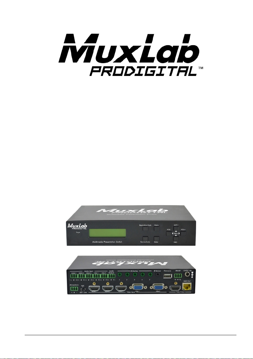
5x1 HDMI / HDBT
Multimedia Presentation
Switch
Installation Guide
500435
© MuxLab Inc. 2015 94-000798-A / SE-000798-A
Page 2

5x1 HDMI / HDBT Multimedia Presentation Switch Installation Guide
SAFETY PRECAUTIONS
To insure the best from the product, please read all instructions carefully before using
the device. Save this manual for further reference.
Follow basic safety precautions to reduce the risk of fire, electrical shock and injury
to persons.
Do not dismantle the housing or modify the module. It may result in electrical shock
or burn.
To prevent f ire or s ho ck haz ar d, do not expose the unit to rain, moisture or i nst all this
product near water. Keep the product away from liquids.
Spillage into the housing m ay resul t in fire, electrical sho ck, or equip me nt damage. If
an object or liquid falls or spills on to the housing, unplug the module immediately.
Do not use liquid or aerosol cleaners to clean this unit. Always unplug the power to
the device before cleaning.
Using supplies or parts not meeting the product’s specifications may cause damage,
deterioration or malfunction.
Refer all servicing to qualified service personnel.
Install the device in a place with good ventilation to avoid damage caused by
overheat.
Unplug the power cord when left unused for a long period of time.
Do not put any heavy items on the unit or on extension cable.
Do not remove the housing of the device as you may be exposed you to dangerous
voltage or other hazards.
Do not twist or pull by force ends of the UTP cable. It can cause malfun ctio n.
Information on disposal of devices: do not burn or mix with general h ouseho ld w aste,
please treat them as norm al electrical wastes.
Unpack the equipment carefully and save the original box and packing material for
possible future shipment
NOTICE:
1. Please read this user manual carefully before using this product.
2. The “far-end” item is the device (e.g. display device, 3
connected via the 500435.
rd
party RS232 device etc.)
© MuxLab Inc. 2015 2
Page 3

5x1 HDMI / HDBT Multimedia Presentation Switch Installation Guide
Contents
1. Introduction ................................................................................................................. 5
1.1 Introduction to the 500435 ................................................................................. 5
1.2 Features ............................................................................................................ 5
1.3 Package Contents ............................................................................................. 5
2. Specification ............................................................................................................... 6
3. Panel Description ........................................................................................................ 8
3.1 The 500435 Front Panel .................................................................................... 8
3.2 The 500435 Rear Panel ................................................................................... 10
4. System Connection ................................................................................................... 11
4.1 Safety Precautions .......................................................................................... 11
4.2 System Diag ram .............................................................................................. 11
4.3 Connection Procedure ..................................................................................... 12
4.4 Connection of Microphone ............................................................................... 12
4.5 Application ....................................................................................................... 14
5. Operations ................................................................................................................ 15
5.1 Operations of Front Panel Buttons .................................................................. 15
5.1.1 Adjusting Resolution .............................................................................. 15
5.1.2 Switching Operations ............................................................................. 15
5.1.3 Adjusting the Volume ............................................................................. 16
5.1.4 On-Screen Display (OSD) Menu ........................................................... 17
5.1.5 Software update: ................................................................................... 17
5.2 Operations of IR .............................................................................................. 18
5.2.1 IR Remote ............................................................................................. 18
5.2.2 IR Operations ........................................................................................ 19
5.3 Operations of CEC Function ............................................................................ 20
5.4 Operations of RS232 Control ........................................................................... 21
5.4.1 RS232 Communication Commands ...................................................... 21
5.4.2 Control the 500435 or 3rd Party Device locally...................................... 29
5.4.3 Control the 500435 l ocally or remotely .................................................. 30
5.5 Operations in OSD Menu................................................................................. 31
5.5.1 Option .................................................................................................... 31
© MuxLab Inc. 2015 3
Page 4

5x1 HDMI / HDBT Multimedia Presentation Switch Installation Guide
5.5.2 Picture ................................................................................................... 32
5.5.3 Sound .................................................................................................... 33
5.5.4 Setup ..................................................................................................... 33
5.6 Instructions of VGA Converting Cable ............................................................. 34
6. Panel Drawing .......................................................................................................... 36
7. Troubles hooting & Maintenance ............................................................................... 37
Regulatory Compliance ................................................................................................ 40
© MuxLab Inc. 2015 4
Page 5

5x1 HDMI / HDBT Multimedia Presentation Switch Installation Guide
1. Introduction
1.1 Introduction to the 500435
The 500435 is a compact scaler switcher with 5 video inputs (3 HDMI, 2 VGA) and 6
audio inputs (3 HDMI audio & 2 VGA audio switched following the video; 1 MIC audio
input). The VGA input supports VGA, Component Video (YPbPr) and Composite Video.
The 500435 scales & switches any vid eo signal to HDMI output and HDBa seT output for
a transmission up to 70 m over a Cat5e/6 with PoC support.
With 1 IR Sensor, 5 IR Emitters and 1 RS232 ports, bidirectional IR & RS232 signals
can be transmitted simultaneously between the 500435 and the HDMI Extender
PoC/PoE Receiver.
1.2 Features
• Supports video source auto-switching function
• Bi-directional IR & RS232 control
• Supports HDMI, VGA, Composite V id eo, and Component Video (YPbPr)
• Output resolutions selectable (1920x1200, 1920x1080, 1600x1200, 1360x768,
1280x800, 1280x720, 1024x768)
• Supports CEC, with commands to enable/disable this function
• Compliant with HDCP
• Supports online software upgrading
• MIC port supports balance/ unbalance signal, and suppresses the external
noise effectively
• 48V phantom power option to support condenser microphone
• 3-level MIC input, supports condenser microphone, dynamic microphone and
wireless microphone
• Controllable via button, IR & RS232
• Powerful OSD function
1.3 Package Contents
• One (1) 5x1 HDMI / HDBT Multimedia Presentation Switch
• Two (2) Mounting wall brackets
• Four (4) Black screws
• Seven (7) Captive screw c onnectors
• One (1) IR Sensor (with carrier wave)
• One (1) IR Emitter
• Two (2) VGA to Component Video (YPbPr) or Composite Video cables
© MuxLab Inc. 2015 5
Page 6
5x1 HDMI / HDBT Multimedia Presentation Switch Installation Guide
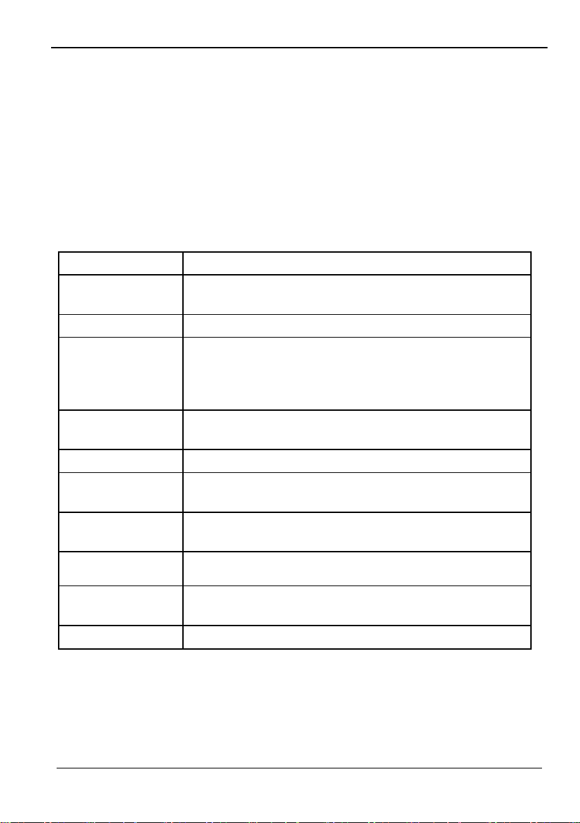
Environment
HDMI 1.3
Devices
DVD, plasma, pr oje ctor s, moni tor s, TV, PC, laptops , serv er s
Transmission
Video Bandwidth
HDMI: 4.96 G b ps
Maximum Pix el
165 MHz
Video Resolution
1920x1200, 1920x1080, 1600x1200, 1360x768, 1280x800,
Audio Impedance
Output: 70 Ω
Stereo Channel
>80dB @1KHz
Signals
HDMI 1.3 protocol an d HDC P
• Two (2) RS232 cable
• Four (4) Plastic cushions with black screws
• One (1) IR remote (T wo AAA batteries needed, not included)
• One (1) 12VDC, 2A Power Adapter with interchangeable blades
• One (1) User Manual
Notes: Please confirm if the product and the accessories are all included, if not,
please contact your dealer.
2. Specification
supporting HDMI
Transpa r e nt t o t he user
Composite Video:150MHz
Component Video (YPbPr): 170MHz
VGA: 375MHz
Clock
Video Impedance
75 Ω
1280x720, 1024x768
Audio Frequency
Response
Separation
© MuxLab Inc. 2015 6
20Hz to 20KHz
Input: >10kΩ
Page 7
5x1 HDMI / HDBT Multimedia Presentation Switch Installation Guide
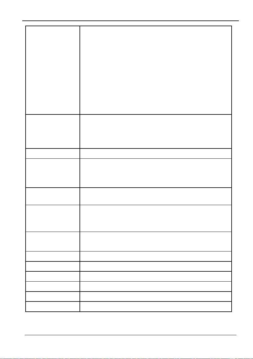
Connectors
Four (4) HDMI recept acl es; T hree ( 3) Inp ut s & One (1) Output.
Note: HDMI cables not included.
Maximum Dis tance
Cat 5e/6: 230 ft (70 m) up to 1080 p
Cable
One (1) Cat 5e /6 or better twisted pair cable required
Compatible
500451-RX (No Se ri al Po rt, No PoE)
Power Supply
Power
8 Watts for the 500435 alone.
Enclosure
Metal
Dimensions
8.66” x 1.73” x 5.83” (220 x 44 x 148 mm)
Weight
Compliance
Regulatory: FCC, CE, RoHS
Warranty
2 years
Order Information
Two (2) VGA HD-15 receptacles (Inputs).
One (1) RJ45 for HDB T (output).
Six (6) 3-pin term ina l bloc k (3.81 mm) for Audio; Five (5) Inputs
& one (1) O ut put.
One (1) 3-pin terminal block (3.81 mm) for the mic roph on e.
Five (5) IR Em itt er 3 .5 m m Mono jacks.
One (1) IR Sensor 3.5m m Ster eo ja ck.
One (1) 3-pin terminal block (3.81 mm) for RS232.
One (1) 2.1mm barrel jack for Power.
One (1) USB Type A.
Based on a maximum
length of 6.6 ft. (2 m) of
HDMI cable per end.
Receiver
Note: When installed in an electrically noisy environment, an STP
cable must be used. Also, cross-connection reduces the
effective distance depending on the grade o f twisted cable used.
500454-RX (With Seri a l Port, No PoE)
500454-POE-RX (With Ser i al Port and PoE)
One (1) 110-240V/12VDC pow er sup ply w ith in te rcha nge ab le
blades
Consumption
16 Watts w he n the 500435 provides PoE power to the HDMI
Extender Re ce iv ers.
Temperature Operating: 0° to 40°C Storage: -20° to 85°C
Humidity: Up to 9 5% non-condensing
0.65 kg
500435 5x1 HDMI / HDBT Multimedia Presentation Switch
© MuxLab Inc. 2015 7
Page 8
5x1 HDMI / HDBT Multimedia Presentation Switch Installation Guide
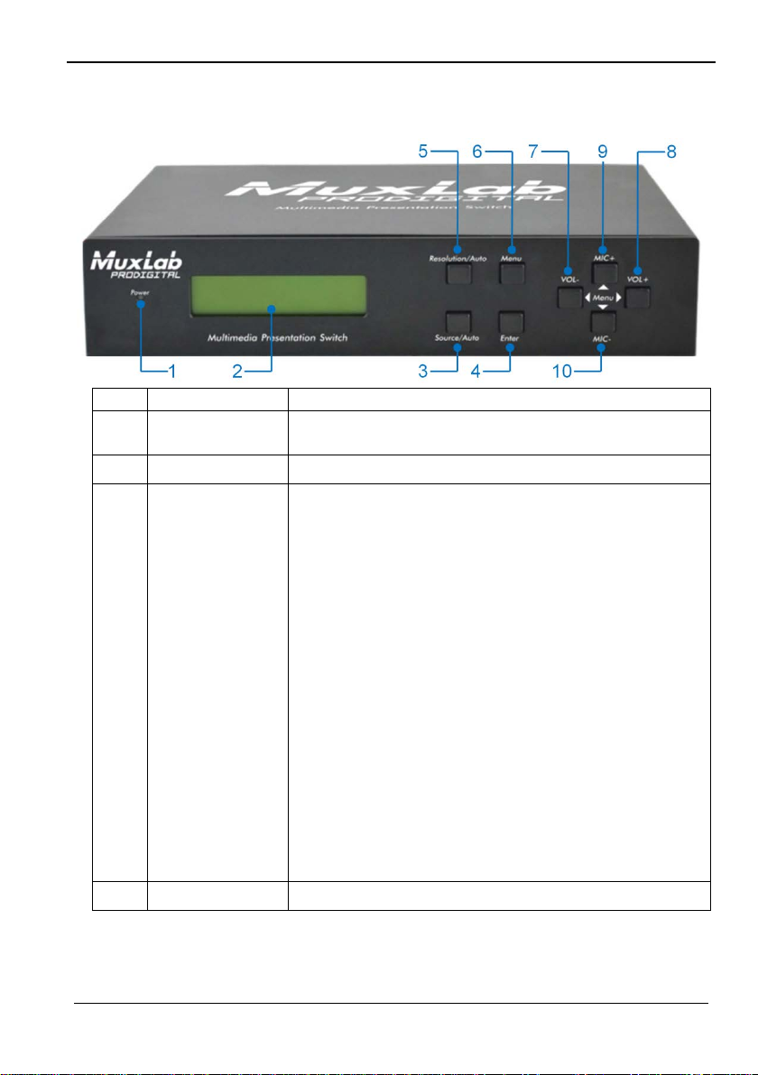
No.
Name
Description
1
Power indicator
Turns on red when power is on, turns green in standby
mode.
3
Source/Auto
• Used as video source selection button, press to
4
Enter
Confirm selection in menu.
3. Panel Description
3.1 The 500435 Front Panel
2 LCD screen
Shows real-time system working status.
select one source, press again to select next source,
switching circularly between HDMI1, HDMI2, HDMI3,
VGA1 and VGA2. The LCD screen will show the
name of selected source.
• Used as switching mode selection button, press and
hold for 7 seconds or more to enter the
Auto-switching mode, press and hold for 7 seconds
or more again to enter the Manual-switchi ng mode.
Note: When setting any VGA port to AV or YPbPr in
Manual-switching mode, the system will not be able
detect video and to enter the Auto-switching mode.
While in Auto-switching mode, setting any VGA port
to AV or YPbPr will automatically revert to
Manual-switching mode, and the LCD screen and
RS232 control software will prompt “Not supported!”.
© MuxLab Inc. 2015 8
Page 9
5x1 HDMI / HDBT Multimedia Presentation Switch Installation Guide
No.
Name
Description
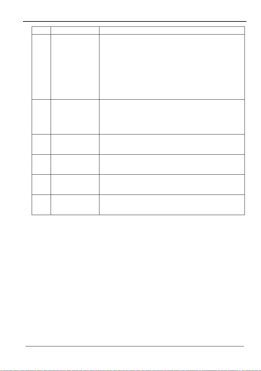
5
Resolution/Auto
• Used as output resolution manual switching button,
• Used as menu button, press to enter the OSD menu.
8
MIC+
• Used as MIC volume up button.
• Used as volume up button.
select among 1920x1200, 1920x1080, 1600x1200,
1360x768, 1280x800, 1280x720, 1024x768.
• Used as output resolution switching mode selection
button, press and hold for 7 seconds or more to
enter in Auto-switching mode, press and hold for 7
seconds or more again to ent er the
Manual-switching mode.
6 Menu
• Used as software updating button, press and hold for
7 seconds or more to enter the software updating
procedure.
7 VOL-
9 VOL+
10
MIC-
• Used as volume down button.
• Used as direction button NEXT in m enus.
• Used as direction button MOVE UP in menus.
• Used as direction button PREVIOUS in menus.
• Used as MIC volume down button.
• Used as direction button MOVE DOWN in menus.
© MuxLab Inc. 2015 9
Page 10
5x1 HDMI / HDBT Multimedia Presentation Switch Installation Guide
No.
Name
Description
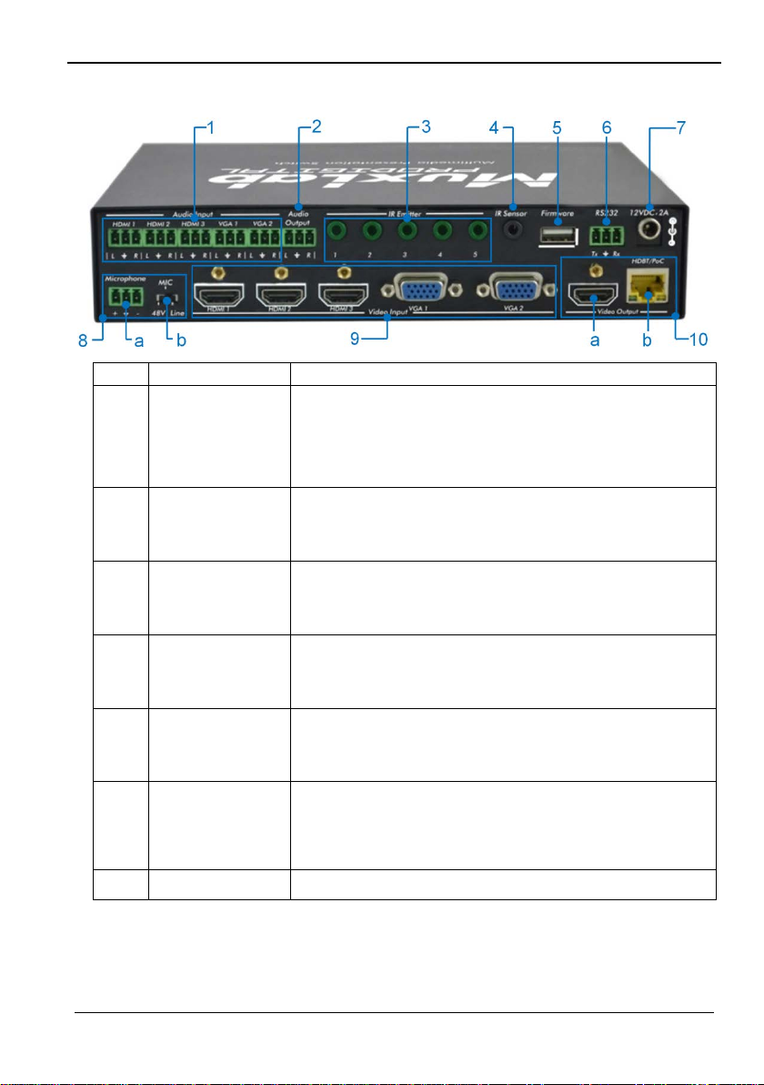
Includes 3 HDMI audio & 2 VGA audio inputs
3
IR Emitter
Five IR Emitter ports connect with IR emitters to control
5
Firmware
This USB port connects with USB flash disk or other
6
RS232
This Serial c ontrol port, 3-pin term inal block connector,
or other devices connected with
HDMI Extender Receivers.
3.2 The 500435 Rear Panel
1 Audio Input
User can choose embedded HDMI audio or external
input audio for HDMI audio input. It is controllable by
RS232 commands.
2 Audio Output Audio output port, the audio comes from the input audio
corresponding to the selected video source and mixed
with MIC audio.
local source devices or the 500435 from remote,
switched along with the corresponding video source.
4 IR Sensor Connects with IR Sensor (with carrier wave only), to
receive IR signal sent by the IR remote or remote
controller of other input/output dev ice.
storage device loaded with the firmware update file, to
update the system firmware.
connects to a control device (such as a computer) to
control the 500435
7 12VDC, 2A
© MuxLab Inc. 2015 10
Power port, connects with 12V DC power adapter.
Page 11
5x1 HDMI / HDBT Multimedia Presentation Switch Installation Guide
No.
Name
Description
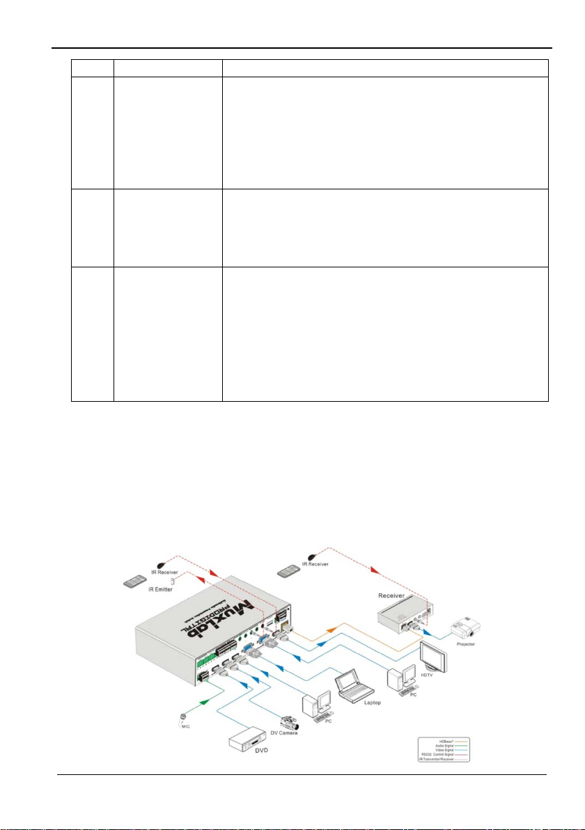
8
Microphone
a) Microphone port: Connects to a microphone
b) Switch that Includes 3 levels: (1) 48V phantom power
mode (connect with condenser microphone),
(2) MIC mode (connect with dynamic microphone)
and (3) LINE mode (connect with wireless
microphone or line audio).
9 Video Input Video input ports, include 3 HD MI inputs & 2 VGA
inputs.
VGA ports suppor t YPbPr, Composite video and VGA
format. Factory default is VGA format.
10
Video Output
a) HDMI local output
b) HDBaseT output, support PoC/PoE.
Both HDMI and HDBT ports share the same audio
signal. The audio signal is mixed with MIC audio and
HDMI embedded audio (output audio). If the HDMI
embedded audio output is disabled, then t here w ill be no
audio present on these ports.
4. System Connection
4.1 Safety Precautions
1) System should be installed in a clean environment with temperature and hum idity
within the operating levels.
2) All devices should be connected before power on.
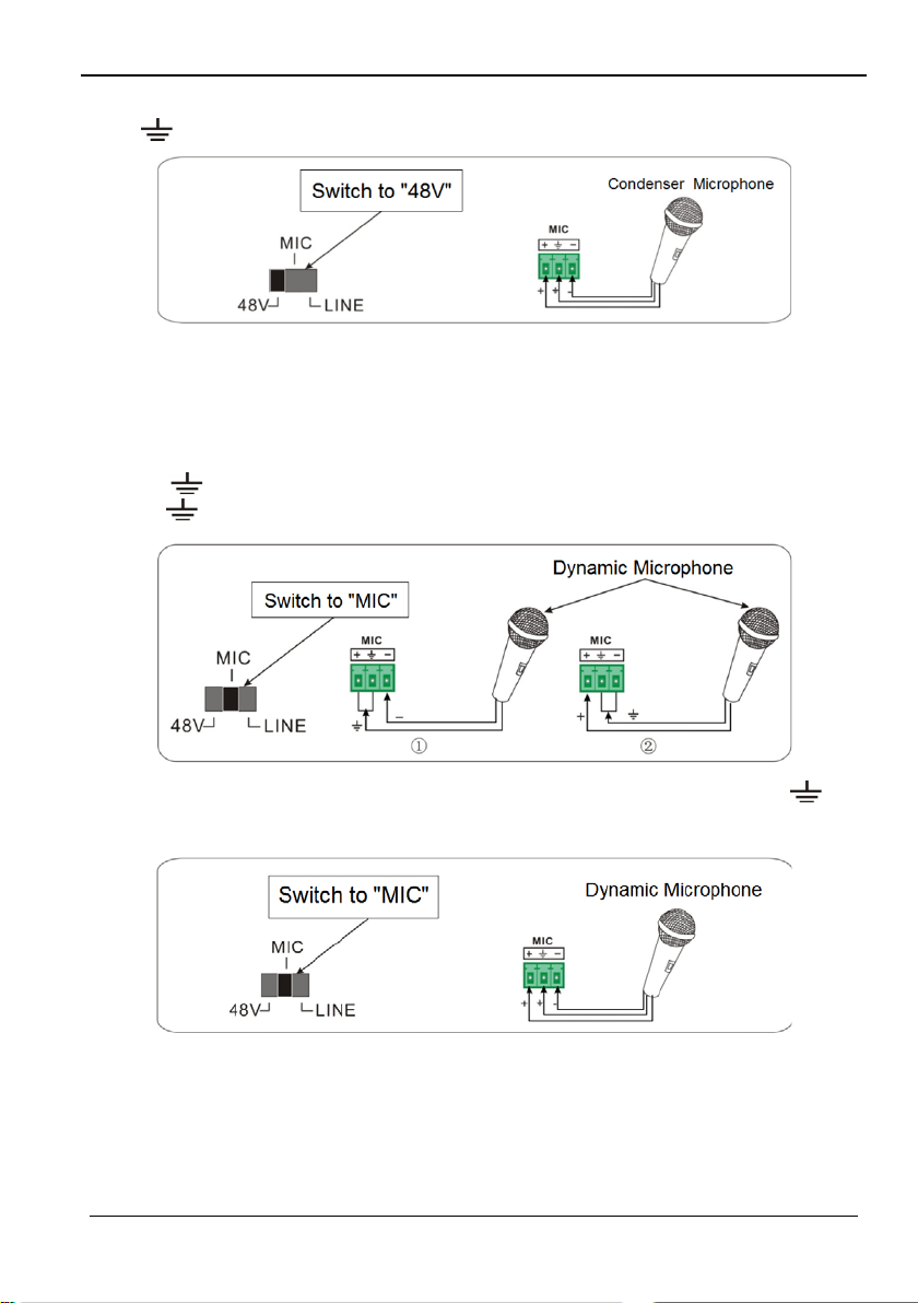
4.2 System Diagram
© MuxLab Inc. 2015 11
Page 12

5x1 HDMI / HDBT Multimedia Presentation Switch Installation Guide
•
•
4.3 Connection Procedure
a) Connect HDMI source devices (e.g. Blue-ray DVD) to HDMI input ports of the
500435 with HDMI cables. Connect VGA source devices (e.g. PC) to VGA input
ports of the 500435 with VGA cables.
b) Connect audio sou rce s to corresponding Audio Input ports on the 500435 with
audio cable. The audio of HDMI can be selected from the embedded audio or from
the external audio.
c) Connect an HDMI display device to the HDMI output port of the 500435 with HDMI
cable.
d) Connect HDMI Extender PoC/PoE Receiver to the HDBaseT output port of the
500435 with a twisted pair Cat5e/6 cable.
e) Connect speakers, headphones or an amplifier to the Audio Output port of the
500435.
f) Connect control device (e.g. PC) to the RS232 port of the 500435; or to the HDMI
Extender PoC/PoE Receiver (with bidirectional RS232 contr ol).
g) Both the 500435 and the HDMI Extender PoC/PoE Receiver have IR sensors and
emitters. When one end is connected with IR sensor, the other end should be
connected with an IR emitter.
For example: When an “IR Sensor” of the 500435 connects to an IR Sensor,
the IR Emitter must be connected to IR Emitter port of HDMI Extender
PoC/PoE Receiver.
The IR signal c an be transmitted in both directions simultane ously between the
500435 and the HDMI Extender PoC/PoE Receiver.
h) Select MIC level and connect the right microphone to Microphone input port. MIC
audio will be transmitted to Audio Output port and mixed with the audio source.
i) Connect 12V DC power to the power port. The HDMI Extender PoC/PoE Receiver
will get power from the 500435 via PoC/PoE function.
4.4 Connection of Microphone
The 500435 provides with 3-level microphone input port, to accommodate different
microphone input modes, including 48V phantom power mode, MIC mode & LINE mode.
48V phantom power input:
The 48V phantom power input has a good frequency characteristic, high input
impedance and high sensitivity.
When switching to “48V”, the MIC input will provide a 48V phantom power. This is only
used for condenser microphones.
© MuxLab Inc. 2015 12
Page 13
5x1 HDMI / HDBT Multimedia Presentation Switch Installation Guide
Connect the microphone as follows: “+” connects to positive, “-” connects to negative
and “ ” to ground.
MIC input
MIC input has a low frequency characteristic, and a wide frequency response.
When switched to “MIC”, the microphone input is us ed for connecting with a dynamic
microphone. There are two different connection methods:
1) Unbalanced connection:
“+” and “ ” connect to ground, and “-” connects to signal.
“-” and “ ” connect to ground, and “+” connects to signal.
2) Balanced connection: “+” connects to positive, “-” connects to negative and “ ”
connects to ground.
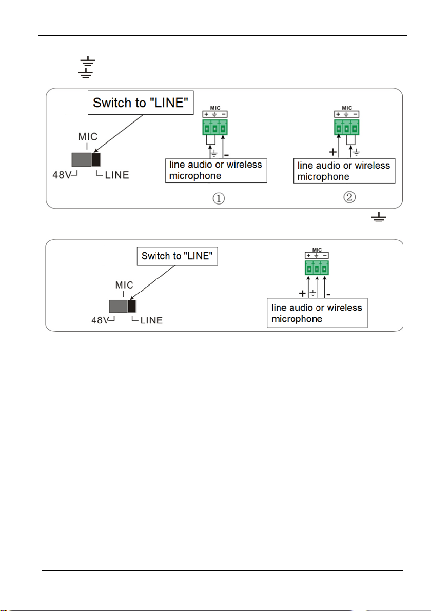
LINE input
LINE input has a low frequency characteristic, and a wide frequency response.
When switched to “LINE”, the microphone input is used for connecting with line audio or
wireless microphone output. There are two different connection methods:
© MuxLab Inc. 2015 13
Page 14
5x1 HDMI / HDBT Multimedia Presentation Switch Installation Guide
1) Unbalanced connection:
“+” and “ ” connect to ground, and “-” connects to signal.
“-” and “ ” connect to ground, and “+” connects to signal.
2) Balanced connection: “+” connects to positive, “-” connects to negative and “ ”
connects to ground.
4.5 Application
The 500435 product can be used in multiple applications, such as computer realm,
monitoring, conference room, big screen display, television education, command &
control center, smart home, etc.
© MuxLab Inc. 2015 14
Page 15

5x1 HDMI / HDBT Multimedia Presentation Switch Installation Guide
IN: HDMI1 MANUAL
IN: HDMI1 AUTO
5. Operations
5.1 Operations of Front Panel Buttons
Front panel buttons can be used for adjusting output resolution, switching operations,
software updating, volume adjusting and other operations in the menus.
5.1.1 Adjusting Resolution
There are two modes available: auto-adjust and manual-adjust. Press and hold the
Resolution/Auto button for 7 seconds or more to switch between auto-adjust and
manual-adjust modes.
Note:
1) In auto-adjust mode, the 500435 will choose the res olution of the display device at
the far-end as the preferred resolution. If you need to choose the res olution of a
local HDMI display device, follow the steps below:
• Turn off the p ower of the 500435 and disconnect the HDMI Extender PoC/PoE
Receiver.
• Turn on the power of the 500435.
• The 500435 gets the resolution of the local HDMI output device.
• Connect the HDMI Extender PoC/PoE Receiver to the 500435.
2) In auto-switch mode, the front panel but t on c ontrol is not active, but it is possible to
switch modes from the IR or RS232 controls.
5.1.2 Switching Operations
Video signals support auto-switching and manual-switching. Press and hold
Source/Auto button for 7 seconds or more to enter the auto-switching or the
manual-switching mode.
The display result is showed as below :
1280 X 720
1280 X 720
The display result will be showed for 2 seconds.
© MuxLab Inc. 2015 15
Page 16

5x1 HDMI / HDBT Multimedia Presentation Switch Installation Guide
Auto-switching function:
The auto-switching functi on w orks as fol lows:
New input
When a new input signal is detected, the 500435 will switch to this new signal
automatically.
Signal loss
When the current display signal is lost, the 500435 will detect other input signals with
priority from INPUT 1 to INPUT 5. It will detect the first signal and switch it to the
output devices.
Power reboot
The 500435 offers the function to remember the last displayed signal when
rebooting. Once rebooted, the 500435 will automatically enter auto-switching mode,
and then detect all inputs and memorize their connection status for future rebooting.
If the last displayed signal is still available, the 500435 will output that signal. If not,
there will be no signal on output devices.
Note: Auto-sw itch ing fun ctio n w orks only when a new signal is detected, when a
signal lost or when rebooting the unit. When any VGA input port is set to AV
or YPbPr, the system will always stay in Manual-switching mode.
Operation Examples:
• Connect Input 2, Input 4, and Input 5 ports with source devices, select Input 4.
• Press and hold Source/Auto button for 7 seconds or more to enter the
auto-switching mode.
• The 500435 i s now in auto-switching mode. If there is no signal loss or no new input,
the Output will still be connected to Input 4.
• Connect Input 3 w ith an act ive source device; the outputs will automatically connect
to Input 3.
• Remove the signal of Input 3; the 500435 will detect from Input 1 to Input 5, and will
automatically switch to Input 2.
• Turn off the power of the 500435. As the 500435 is in auto-switching mode, it will
choose Input 2 to output when power is restored.
5.1.3 Adjusting the Volume
When not in OSD menu, press VOL – to decrease line volume, VOL + to increase line
volume; press MIC – to decrease MIC volume, MIC + to increase MIC volume.
© MuxLab Inc. 2015 16
Page 17

5x1 HDMI / HDBT Multimedia Presentation Switch Installation Guide
5.1.4 On-Screen Display (OSD) Menu
Press Menu button to enter the OSD menu. Use Up, Down, Left, Right buttons to
navigate, and press Enter to confirm your selection. The Menu button also can be used
to exit present menu and go to the previous menu level by level until you exit the OSD.
5.1.5 Software update:
The firmware of the 500435 can be updated via USB flash disk.
Procedures:
1) Copy the file “MERGE_51T.bin” to the root directory of a U S B flash dis k. (Make sure
the file is copied to the root directory for normal use. The “MERGE_51T.bin” f ile is
provided by MuxLab and is available on our website: http://www.muxlab.com
2) Plug the USB flash disk to the 500435 USB port on its front panel.
3) Press the Menu button for 7 s econds or more to update the software automatically.
You can also press the Menu button for 1 second to enter the OSD menu, go to
“Option” Select “Software Update” to enter the update procedure.
Or you can send the command 50689% via the RS232 port to update the software.
).
© MuxLab Inc. 2015 17
Page 18
5x1 HDMI / HDBT Multimedia Presentation Switch Installation Guide
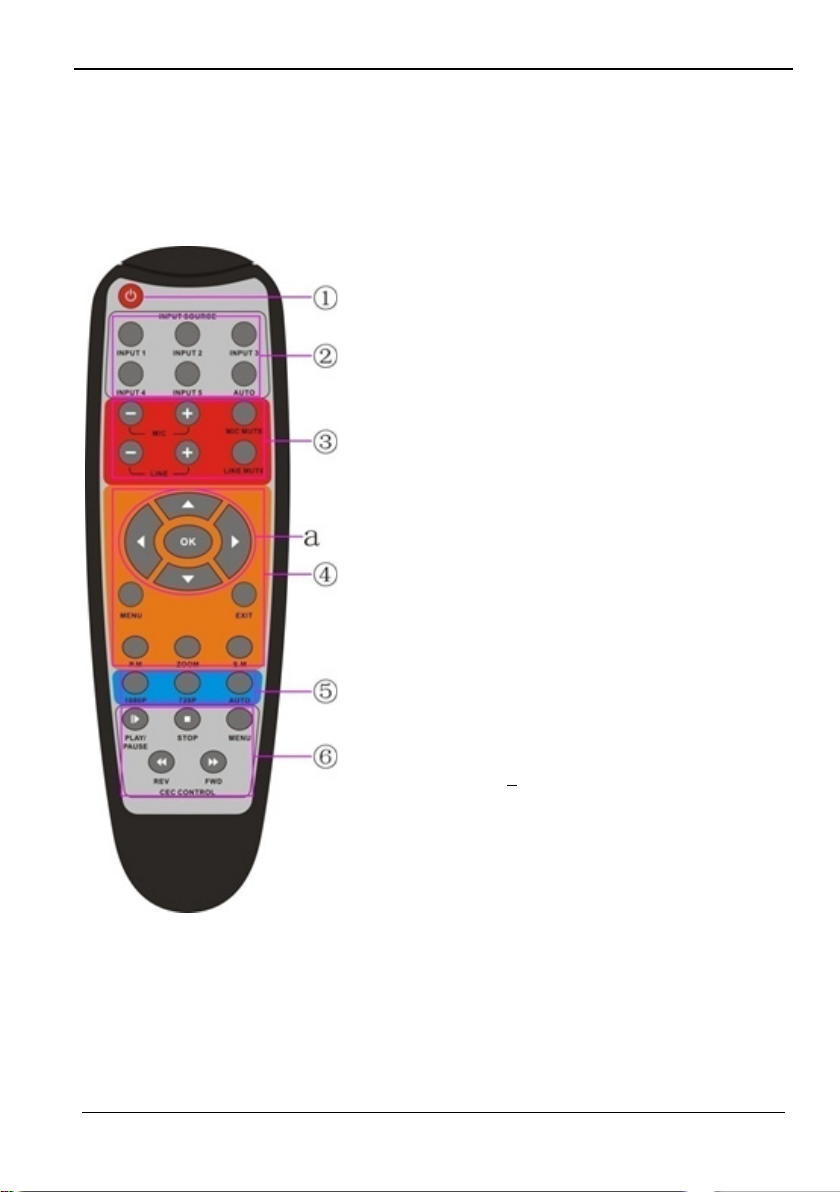
1. Power button
2.
3.
4.
5.
6.
FWD (forward).
5.2 Operations of IR
5.2.1 IR Remote
As IR signal can be transmitted in both directions between the 500435 and the HDMI
Extender PoC/PoE Receiver, it is able to use the IR remote at the far-end to control the
500435 or HDMI source devices (via CEC function buttons).
Enter/exit power standby mode
Input channel selection buttons
Input 1 is for HDMI1, Input 2 for HDMI2…and
Input 5 for VGA2.
AUTO: Enable/ disable auto-switching mode.
Volume adjusting buttons
MIC-/+: increase/ decrease MIC volume
LINE-/+: increase/ decrease line volume
MIC MUTE: mute/ unmute MIC audio
LINE MUTE: mute/ unmute line audio
Menu operation buttons
MENU: press to enter the OSD menu or to return
to previous menu.
EXIT: exit OSD menu.
OK: confirm button.
,,, : UP/DOWN/LEFT/ RIGHT buttons, for
value setting or page-turn.
Buttons in area “a” are also used in CEC mode to
enter the menu of the HDMI source device.
P.P, ZOOM, S.M: shortcut button, to select display
mode.
Resolution selection buttons
Select resolution by pres sing the corresponding
button.
AUTO: Enable / disable auto-switching mode.
CEC function buttons
For HDMI devices which supports CEC. It includes
PLAY, PAUSE, STOP, MENU, REV (reverse) and
© MuxLab Inc. 2015 18
Page 19
5x1 HDMI / HDBT Multimedia Presentation Switch Installation Guide
5.2.2 IR Operations
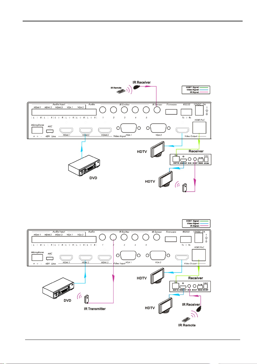
The 5 IR Emitter ports correspond to the 5 video inputs respectively, and the IR signals
are switched following the corresponding video source.
1) Control far-end device from local
From the 500435, you can control the far-end display dev ice locally with the
corresponding IR remote.
2) Control local device from remote
You can control the source device or the 500435 locally with corresponding IR remote.
© MuxLab Inc. 2015 19
Page 20
5x1 HDMI / HDBT Multimedia Presentation Switch Installation Guide
Situation
Working Status
devices also exit the standby mode.
CEC: on,
Standby: off
Press STANDBY button on the IR remote, The 500435 enters
the Standby mode, HDMI1~3 source devices stay On.
control the HDMI source devices
CEC: off
Disables all CEC functions.
5.3 Operations of CEC Function
The 500435 supports CEC f un ctio n. This function can be turned on/ off by software
commands (RS232) or by OSD menu operations. The factory default setting is ON.
Software CEC commands are: “50686%” (enable CEC) and “50687%” (disable CEC).
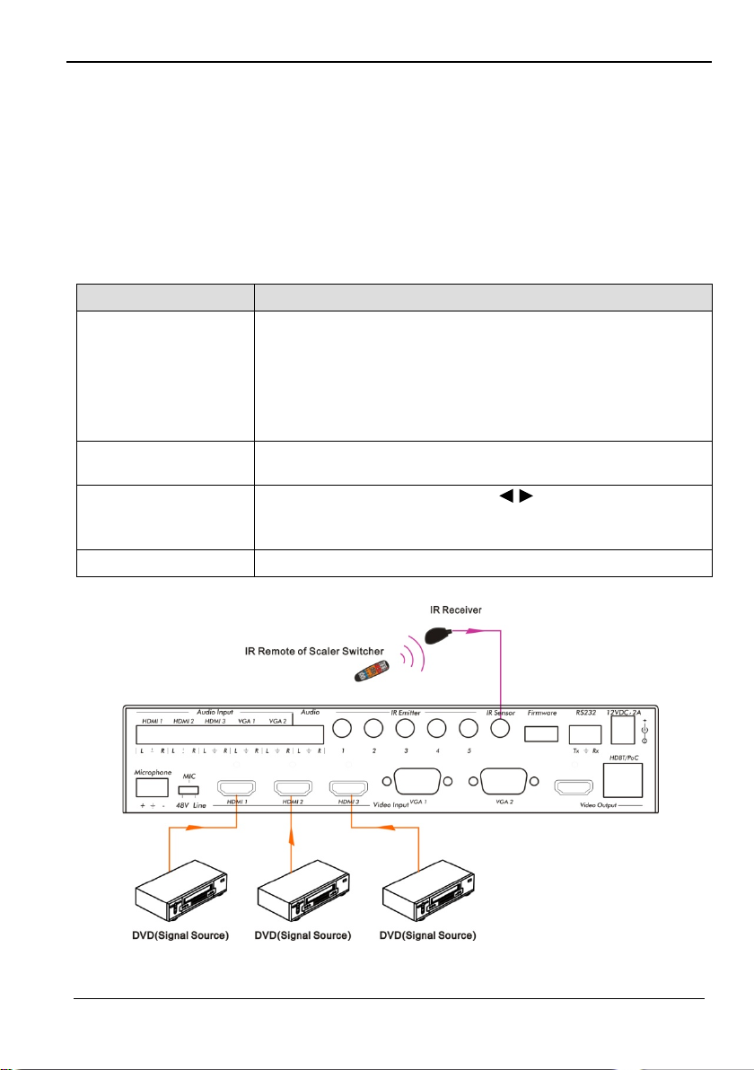
HDMI Input ports 1~3 support CEC, if the connected source devices also support CEC
and their CEC functions are enabled, you can control the source device via the IR
remote of the 500435.
The working status related to CEC and STANDBY is showed as below:
Press STANDBY button on the IR remote, the 500435 enters
the Standby mode, so do all the CEC enabled HDMI source
CEC: on,
Standby: on
devices.
Press STANDBY button again on the IR remote, the 500435
exits the standby mode, the CEC enabled HDMI source
Use CEC function buttons,
CEC: on
CEC: Control HDMI source devices by IR remote
© MuxLab Inc. 2015 20
Fast Forward, and Reverse buttons on the IR remote to
▲,▼, , , OK, Play, Pause,
Page 21
5x1 HDMI / HDBT Multimedia Presentation Switch Installation Guide
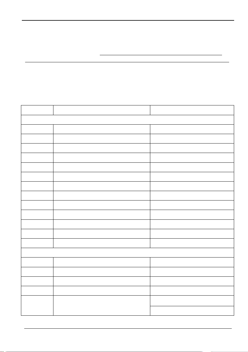
5.4 Operations of RS232 Control
Since RS232 can be transmitted in both directions between the 500435 and the HDMI
Extender PoC/PoE Receiver, you are able to control a third party RS232 device locally
or control the 500435 remotely. For compatibility with third party RS232 devices, the
baud rate of the devices should be 2400, 4800, 9600, 19200, 38400, 57600 or 115200.
You can use a terminal software to control 500435. Please set the parameters of the
COM Port (baud rate, data bit, stop bi t and the parity bit) to 9600, 8, 1, none.
5.4.1 RS232 Communication Commands Communication protocol: RS232 Communication Protocol
(Baud rate: 9600, Data bit: 8, Stop bit: 1, Parity bit: none)
Command Function Feedback Example
Switch Commands
50701%
50702%
50703%
50704%
50705%
50680%
50681%
50682%
50683%
50684%
50685%
50785%
50786%
50600%
50601%
50602%
50603%
50720%
Switch to HDMI 1 input Switch to HDMI 1
Switch to HDMI 2 input Switch to HDMI 2
Switch to HDMI 3 input Switch to HDMI 3
Switch to VGA 1/YPbPr 1/AV 1 input Switch to VGA 1/YPbPr 1/AV 1
Switch to VGA 2/YPbPr 2/AV 2 input Switch to VGA 2/YPbPr 2/AV 2
Select VGA 1 for INPUT 4 Input 4 Set & Switch to VGA 1
Select YPbPr 1 for INPUT 4 Input 4 Set & Switch to YPbPr1
Select AV 1 for INPUT 4 Input 4 Set & Switch to AV 1
Select VGA 2 for INPUT 5 Input 5 Set & Switch to VGA 2
Select YPbPr 2 for INPUT 5 Input 5 Set & Switch to YPbPr 2
Select AV 2 for INPUT 5 Input 5 Set & Switch to AV 2
Enable auto-switching Auto Switching
Disable auto-switching Manual Switching
Audio Commands
MUTE line audio LINE Mute
Unmute line audio LINE Unmute
Line audio volume up LINE Volume: xx (xx=0~60)
Line audio volume down LINE Volume: xx (xx=0~60)
LINE Mute
Mute LINE audio & MIC audio
MIC Mute
© MuxLab Inc. 2015 21
Page 22
5x1 HDMI / HDBT Multimedia Presentation Switch Installation Guide
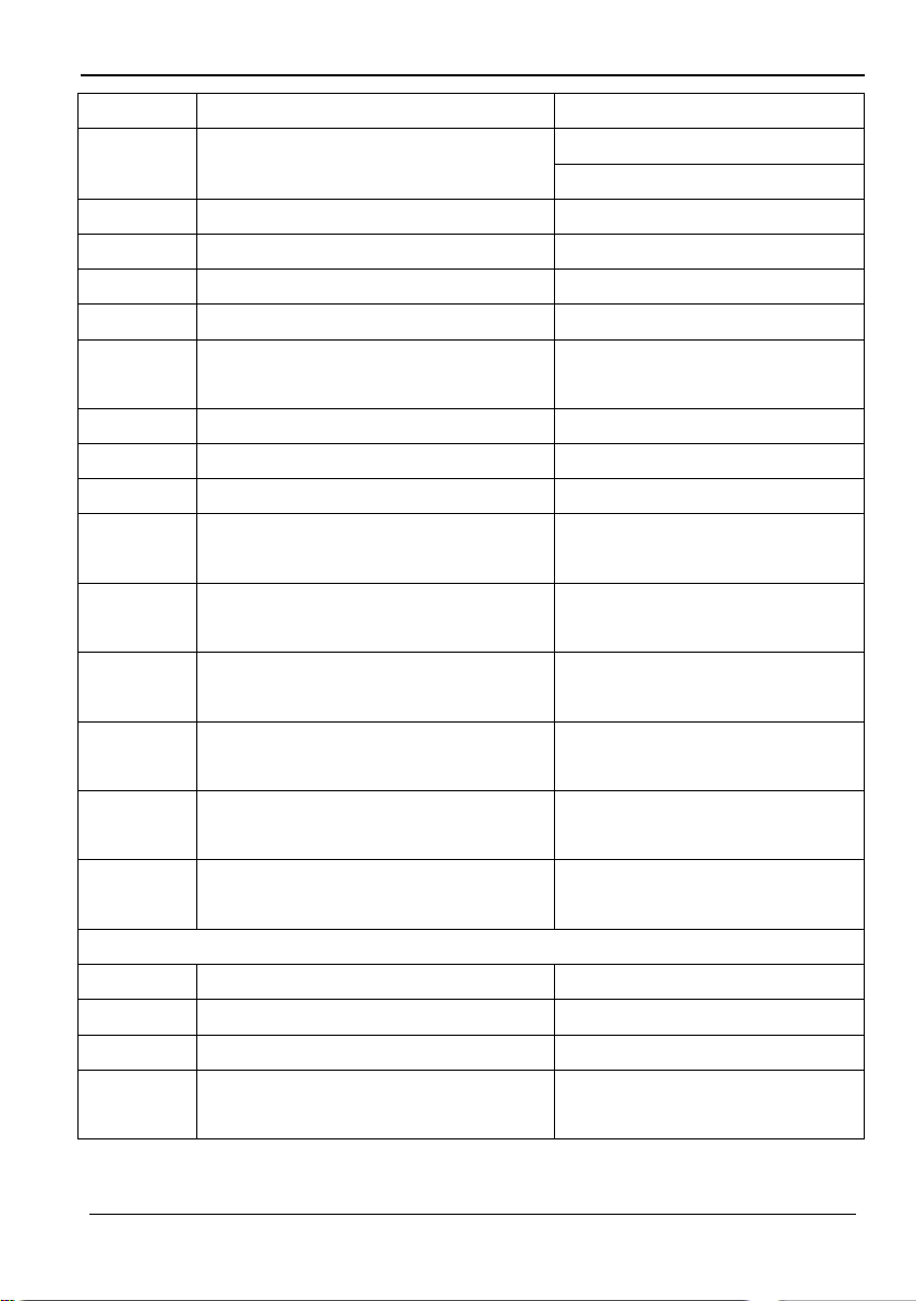
Command Function Feedback Example
50721%
50722%
50723%
50694%
50695%
50696%
50724%
50725%
508xx%
50706%
50707%
50708%
50709%
50710%
50711%
50619%
50626%
50627%
50628%
Unmute LINE audio & MIC audio
Mute MIC audio MIC Mute
Unmute MIC audio MIC Unmute
Enable MIC precedence MIC precedence: enable
Disable MIC precedence MIC precedence: disable
Check MIC precedence status
MIC volume up MIC Volume: xx (xx=0~60)
MIC volume down MIC Volume: xx (xx=0~60)
Set MIC volume MIC Volume: xx (xx=0~60)
Choose embedded audio as HDMI 1
audio input
Choose external audio as HDMI 1
audio input
Choose embedded audio as HDMI 2
audio input
Choose external audio as HDMI 2
audio input
Choose embedded audio as HDMI 3
audio input
Choose external audio as HDMI 3
audio input
Resolution Commands
Change resolution to 1360x768 HD Resolution: 1360x768
Change resolution to 1024x768 XGA Resolution: 1024x768
Change resolution to 1280x720 720p Resolution: 1280x720
Change resolution to 1280x800
WXGA
LINE Unmute
MIC Unmute
MIC precedence: XXXX (XXXX=
enable / disable)
HDMI 1 Audio from Embedded
HDMI 1 Audio from LINE
HDMI 2 Audio from Embedded
HDMI 2 Audio from LINE
HDMI 3 Audio from Embedded
HDMI 3 Audio from LINE
Resolution: 1280x800
© MuxLab Inc. 2015 22
Page 23
5x1 HDMI / HDBT Multimedia Presentation Switch Installation Guide
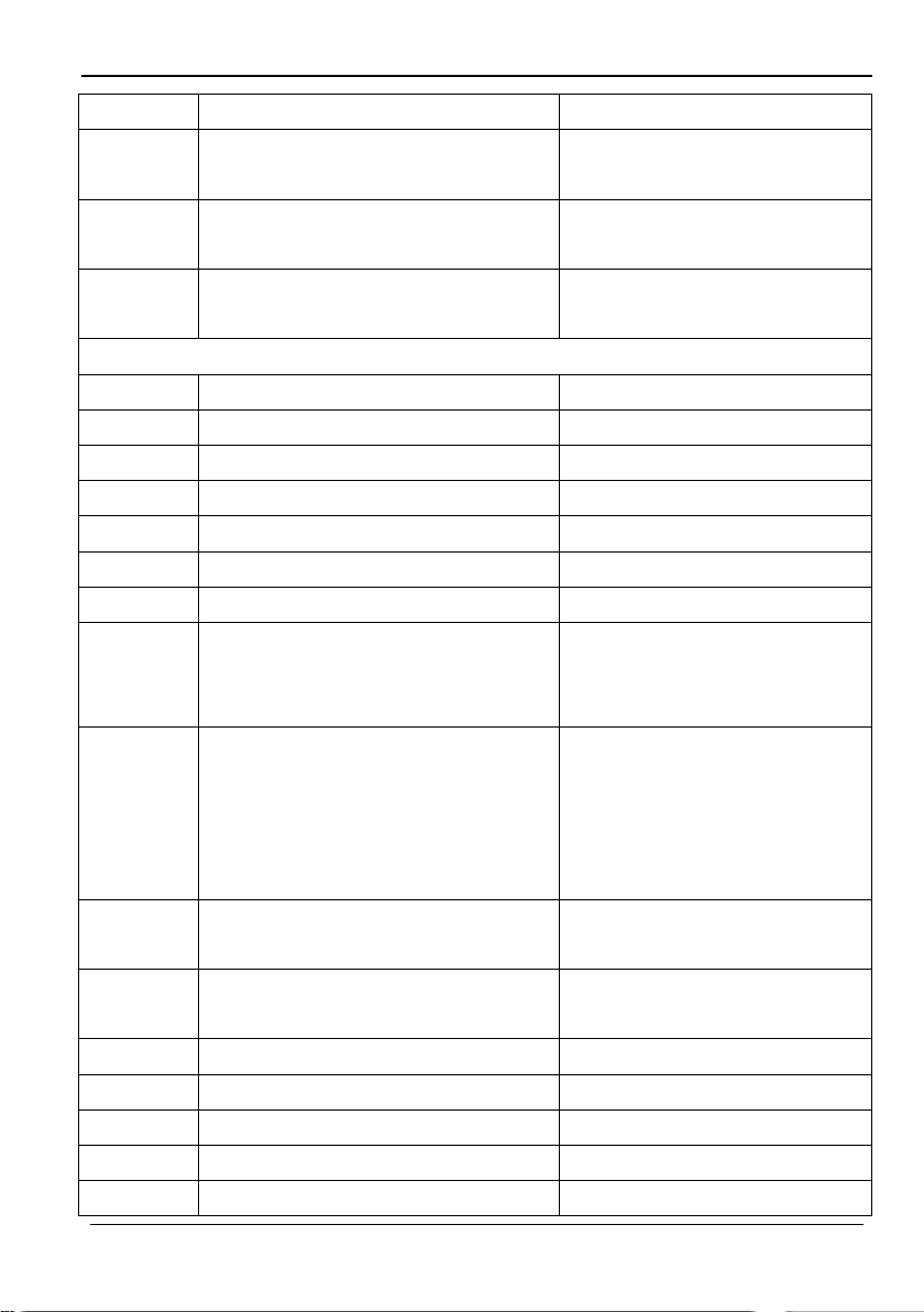
Command Function Feedback Example
50629%
50620%
50621%
50604%
50605%
501xx%
502xx%
503xx%
504xx%
505xx%
50607%
50608%
50614%
50615%
50655%
50656%
50646%
50647%
50648%
Change resolution to 1920x1080
1080p
Change resolution to1920x1200
WUXGA
Change resolution to1600x1200
UXGA
Setup Commands
Lock the front panel buttons Front Panel lock
Unlock the front panel buttons Front Panel Unlock
Set the volume to xx. LINE Volume: xx (xx=0~60)
Set the brightness to xx. Brightness: xx (xx=0~99)
Set the contrast to xx. Contrast: xx (xx=0~99)
Set the saturation to xx. Saturation: xx (xx=0~99)
Set the sharpness to xx. Sharpness: xx (xx=0~99)
Adjust the color temperature
Set the aspect ratio
Set the picture mode
Set SM audio mode
Freeze output image Freeze: enable
Cancel the freezing of output image Freeze: disable
Enable MIC Volume Icon display Volume Icon: enable
Disable MI C Volume Icon display Volume Icon: disable
Enable HDMI embedded audio output Embedded Audio Output: enable
Resolution: 1920x1080
Resolution: 1920x1200
Resolution: 1600x1200
Color Temperature: xx
(xx= Cool/ Medium/ Warm/
User.)
Aspect Ratio: xx (xx= 16:9/ 4:3/
auto/ panorama/ justscan/
zoom1/ zoom2, when the input
source is VGA format, xx can
only be 4:3, 16:9 or Panorama)
Picture Mode: xx (xx= Dynamic/
Standard/ Mild/ User)
Sound Mode: xx (xx= Standard/
Music/ Movie/ Sports/ Us er)
© MuxLab Inc. 2015 23
Page 24
5x1 HDMI / HDBT Multimedia Presentation Switch Installation Guide
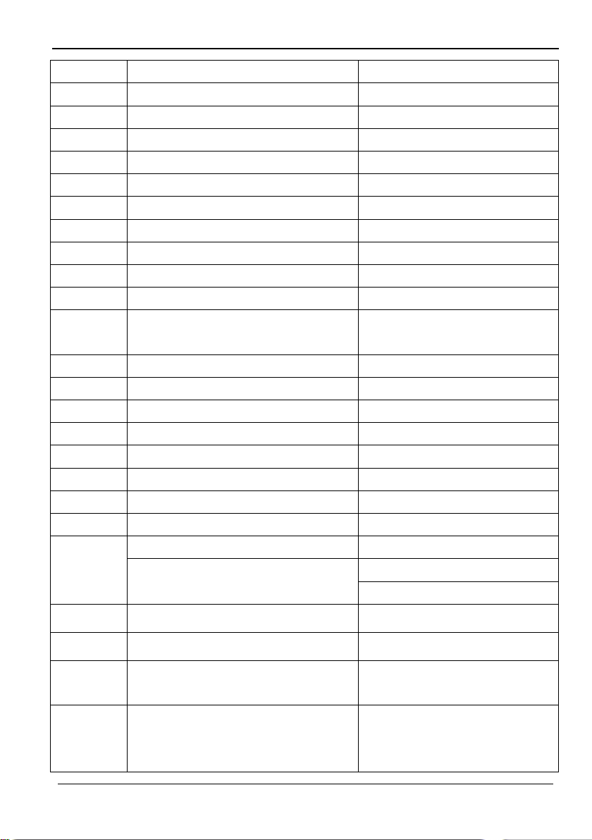
Command Function Feedback Example
50649%
50761%
50762%
50763%
50764%
50765%
50766%
50644%
50645%
50650%
50606%
50699%
50688%
50689%
50690%
50791%
50792%
50793%
50794%
50795%
50767%
Disable HDMI embedded audio output Embedded Audio Output: disable
Not display mute icon of LINE audio LINE Mute Icon: disable
Display mute icon of LINE audio LINE Mute Icon: enable
Not display mute icon of MIC audio MIC Mute Icon: disable
Display mute icon of MIC audio MIC Mute Icon: enable
Display freeze icon Freeze Icon: enable
Not display freeze icon Freeze Icon: disable
Display channel status Input Icon: enable
Not display channel status Input Icon: disable
Check the channel status Input Icon: xx
Auto-adjust the input parameter
(VGA only)
Check the system version Version Vx.x.x
Enable MIC noise detecting MIC detect: enable
Disable MIC noise detecting MIC detect: disable
Check MIC noise detecting status MIC detect: XXXX
HDCP Active HDCP Active
HDCP Manual HDCP Manual
Enable HDCP output HDCP ON
Disable HDCP output HDCP OFF
Inquire HDCP/ Active HDCP HDCP Active
Inquire HDCP/ Manual HDCP
Restore default EDID EDID: initial
VGA Input Auto
HDCP Manual
HDCP OFF/ON
50768%
50769%
50770%
© MuxLab Inc. 2015 24
Bypass EDID data from output to input EDID: bypass
Upload custom EDID data to the
switcher
Inquire EDID status
EDID: user
EDID: initial
EDID: bypass
EDID: user
Page 25
5x1 HDMI / HDBT Multimedia Presentation Switch Installation Guide
Command Function Feedback Example
Manage HDMI input with
preferred timing
Resolution:1920x1080
RS232 Mode 1: RS232 Control
Scaler & Remote
RS232 Mode 2: RS232 &
Remote Control Scaler
50782%
50787%
50788%
50697%
50797%
EDID management, copy the best
resolution data of one output to HDMI
input
Enable serial control mode 1: control
product& far-end from local RS232
Enable serial control mode 2: control
product from local RS232 and far-end)
Exit standby mode Wake up!
Enter standby mode Go to standby!
50698%
50617%
50609%
50610%
50611%
50612%
50613%
50616%
50618%
50630%
50631%
50632%
Software update
Reset to factory defaults Factory Reset
Menu Commands
OK for OSD selection Key: ok
LEFT button Key: left
RIGHT button Key: right
UP button Key: up
DOWN button Key: down
MENU button (enter OSD) OSD: Enter
EXIT button (exit OSD) OSD: Exi t
Inquire Commands
Check the volume level
Check the input source
Check the output resolution
LINE Volume: xx (xx=0~66)
MIC Volume: xx (xx=0~66)
Input: xx (xx=HDMI1/ HDMI2/
HDMI3/ VGA1/ VGA2/ YPbPr1/
YPbPr2/ AV1/ AV2)
Resolution: xx (xx=1920×1200/
1920×1080/ 1600×1200/
1360×768/ 1280×800/
1280×720/ 1024×768
© MuxLab Inc. 2015 25
Page 26
5x1 HDMI / HDBT Multimedia Presentation Switch Installation Guide
Command Function Feedback Example
50633%
50634%
50635%
50636%
50637%
50638%
50639%
50640%
50651%
50652%
50712%
50751%
50752%
50753%
50754%
Check the image mode
Check the audio mode
Check the image aspect ratio
Check the brightness Brightness: xx (xx=0~99)
Check the contrast Contrast: xx (xx=0~99)
Check the saturation Saturation: xx (xx=0~99)
Check sharpness Sharpness: xx (xx=0~99)
Check the color temperature
Check Volume Icon display status Volume Icon: xxxx
Check Digital audio output status
Check the audio input sources for
HDMI 1, 2, 3
Check whether the LINE audio is mute
or not
Check whether the MIC audio is mute
or not
Check the freeze status Freeze: enable/disable
Check the panel lock status Front Panel Lock/UnLock
Picture Mode: xx (xx= Dynamic/
Standard/ Mild/ User)
Sound Mode: xx (xx= Standard/
Music/ Movie/ Sports/ Us er)
Aspect Ratio: xx (xx= 16:9/ 4:3/
auto/ panorama/ justscan/
zoom1/ zoom2, when the input
source is VGA format, xx can
only be 4:3, 16:9 or Panorama)
Color Temperature: xx
(xx= Cool/Medium/Warm/User.)
Embedded Audio Output:
enable/disable
HDMI1 Audio from XXXX port
HDMI2 Audio from XXXX port
HDMI3 Audio from XXXX port
LINE Mute/Unmute
MIC Mute/Unmute
© MuxLab Inc. 2015 26
Page 27
5x1 HDMI / HDBT Multimedia Presentation Switch Installation Guide
Command Function Feedback Example
Line Volume:XX
Mic Volume:XX
Input:XXXX
Resolution:XXXX
Digital Sound Ouput: XXXX
Switch status: XXXX
Output Width Adjust xx
Output Width Adjust xx
Output Height Adjust xx
50783%
50678%
50679%
50670%
50671%
50672%
50673%
50674%
50675%
50676%
Display status including MIC, LINE
audio, Resolution, Output Audio
on/off, Manual/ Auto-switching modes
Adjustment Commands
Enable screen output adjus ting Enter Output Position Adjust
Disable screen output adjusting Exit Output Position Adjust
Move the image to left Output Position Adjust X xx
Move the image to right Output Position Adjust X xx
Move the image up Output Position Adjust Y XX
Move the image down Output Position Adjust Y xx
Stretch left from left side
(increase image width)
Pull right from left side
(decrease image width)
Stretch upwards from bottom side
(decrease image height)
50677%
50687%
50686%
50901%
50902%
50903%
50904%
50905%
50906%
© MuxLab Inc. 2015 27
Stretch downwards from bottom side
(increase image height)
CEC Commands
Disable CEC HDMI CEC OFF
Enable CEC HDMI CEC ON
Play&pause CEC cmd: play&pause
Stop CEC cmd: stop
Menu CEC cmd: menu
Retreat CEC cmd: rev
Forward CEC cmd: fwd
Up CEC cmd: up
Output Height Adjust xx
Page 28
5x1 HDMI / HDBT Multimedia Presentation Switch Installation Guide
Command Function Feedback Example
50907%
50908%
50909%
50910%
50911%
Note:
1. Turn on/ off HDCP auto-manageme nt by send ing seri al co m mand s.
a) When HDCP is set to Active, the output HDCP status follows the input source. If
b) When HDCP is set to Manual, the output HDCP status follows the status of
2. Screen output adjusting is available only when the screen output adjusting is on.
Send command 50678% to turn on.
3. CEC commands with grey background are available only when CEC is on.
4. MIC precedence: In Mute mode, if the MIC noise detecting is on, the device will
unmute MIC automatically given the outer noise exceeds the limit of noise detect ing.
Send the 50696% command to enable MIC precedence; then the device will not be
able to change the mute mode no matter how loud the noise is.
Down CEC cmd: down
Left CEC cmd: left
Right CEC cmd: right
Confirm command CEC cmd: select
Exit command CEC cmd: exit
the input source is with HDCP, so is the output and vice versa.
HDCP. If the HDCP is turned off, then the output is without HDCP.
© MuxLab Inc. 2015 28
Page 29
5x1 HDMI / HDBT Multimedia Presentation Switch Installation Guide
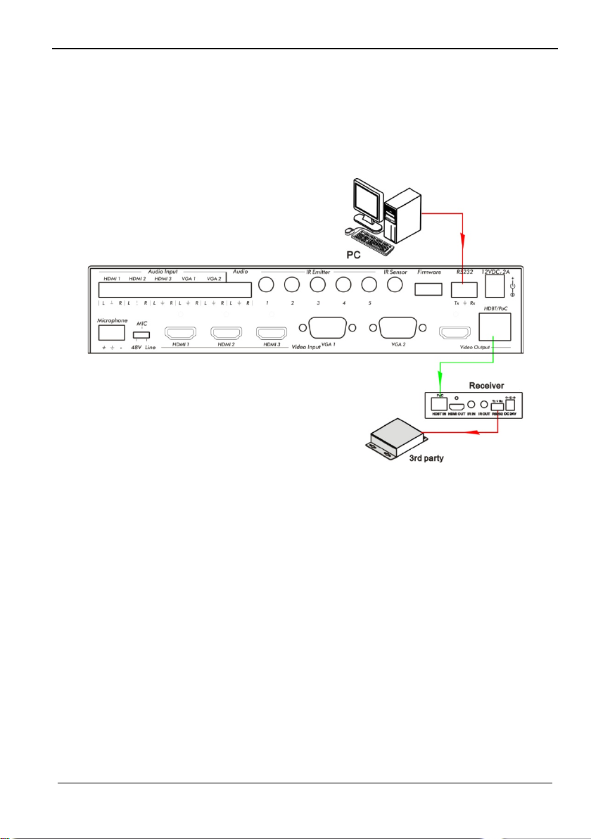
5.4.2 Control the 500435 or 3rd Party Device locally
First, connect the RS232 port of the 500435 to the RS232 port of the PC.
Then, send the 50787% command (Serial control mode 1, factory default) via RS232
communication software.
Finally, send a command to the 500435 or to other remote RS232 device connec ted in
the system. Connect as below:
Control the 500435 or 3rd party device from local
© MuxLab Inc. 2015 29
Page 30
5x1 HDMI / HDBT Multimedia Presentation Switch Installation Guide
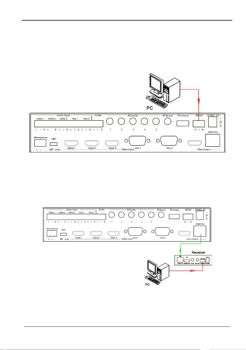
5.4.3 Control the 500435 locally or remotely
1. Control the 500435 locally
First, connect the RS232 port of the 500435 to the RS232 port of the PC.
Then, send the 50788% command via the RS2 32 com mun ic a tion software.
Finally, send a command to control the 500435. Connect as below:
Control the 500435 from local
2. Control the 500435 remotely
First, connect the RS232 port of the far-end RS232 device to the RS232 port of the PC.
Then, send the 50788% command via the RS2 32 com mun ic a tion software.
Finally, send a command to control the 500435. Connect as below:
Control the 500435 from remote
© MuxLab Inc. 2015 30
Page 31
5x1 HDMI / HDBT Multimedia Presentation Switch Installation Guide
5.5 Operations in OSD Menu
The 500435 provides a powerful OSD operation menu that contains 4 sections:
(1) Option settings, (2) Picture settings, (3) Sound settings and (4) System setup.
Press the MENU button on the front panel (or the MENU button on the IR remote, or
send the 50616% RS232 command) to enter the OSD menu.
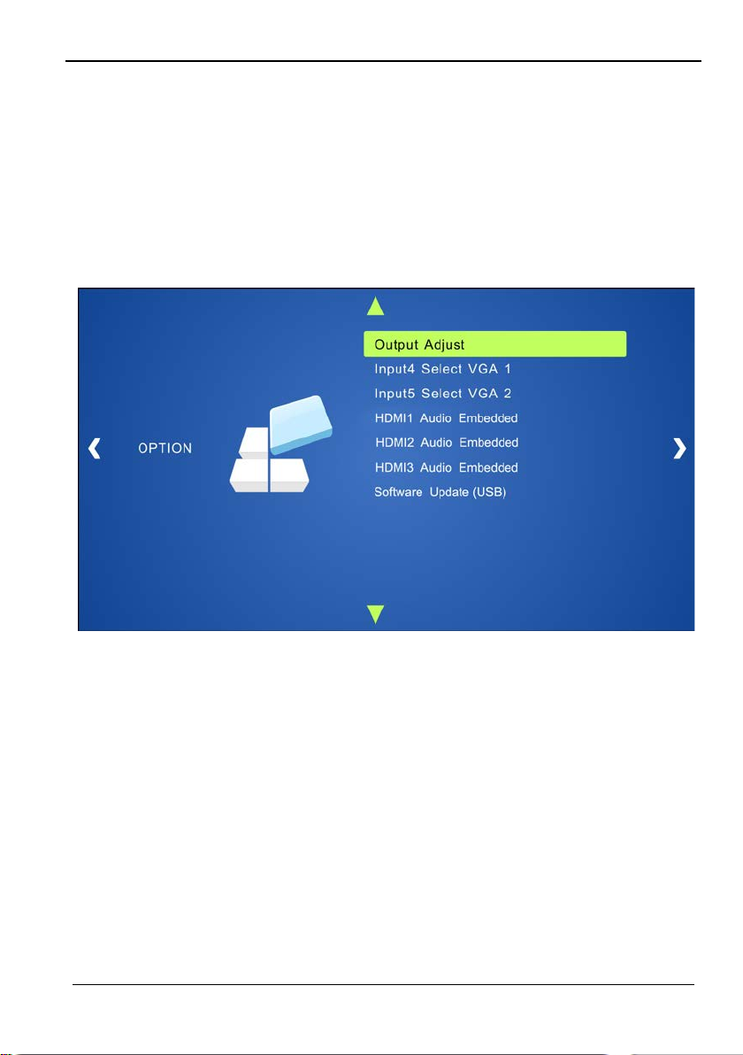
5.5.1 Option
Includes Output Adjust, Input4/5 Select, HDMI1/2/3 Audio select, and Software Update
(USB)
Output Adjust: Adjust output image position (X: horizontal direction and Y: vertical
direction), ratio aspect (width and height), polarity adjustment (H Polarity and V Polarity)
and output setting (HDMI on/off and HDBT on/off).
Input4 Select: Selec t v ide o so ur ce for mat for VGA input, includes AV 1 (C-vid eo signal) ,
VGA 1 (VGA signal) and YPbPr 1 (Component video signal). Press ENTER to switch
among the options, and pr es s Input 4 on the IR remote t o co nfirm the sel ect ion .
Input5 Select: Select video source for VGA input, includes AV 2 (C-video signal), VGA 2
(VGA signal) and YPbPr 2 (Component video signal). Press ENTER to switch among
the options, and press Input 5 on the IR remote to confirm the selection.
For INPUT4 & INPUT5, when change for new format signal:
1. First, please select a format through this menu (the signal format changed whi le the
video source is still the s ame).
2. Then, switch off the present signal channel (e.g. s witch to another channel).
3. Finally, switch to channel INPUT4/INPUT5 again.
© MuxLab Inc. 2015 31
Page 32
5x1 HDMI / HDBT Multimedia Presentation Switch Installation Guide
HDMI1 Audio Select: switch between Embedded and Line to choose the desired audio
output port for HDMI1.
HDMI2 Audio Select: switch between Embedded and Line to choose the desired audio
output port for HDMI2.
HDMI3 Audio Select: switch between Embedded and Line to choose the desired audio
output port for HDMI3.
Software Update (USB): Insert the USB flash disk with updating file to USB port of
500435, to update the software.
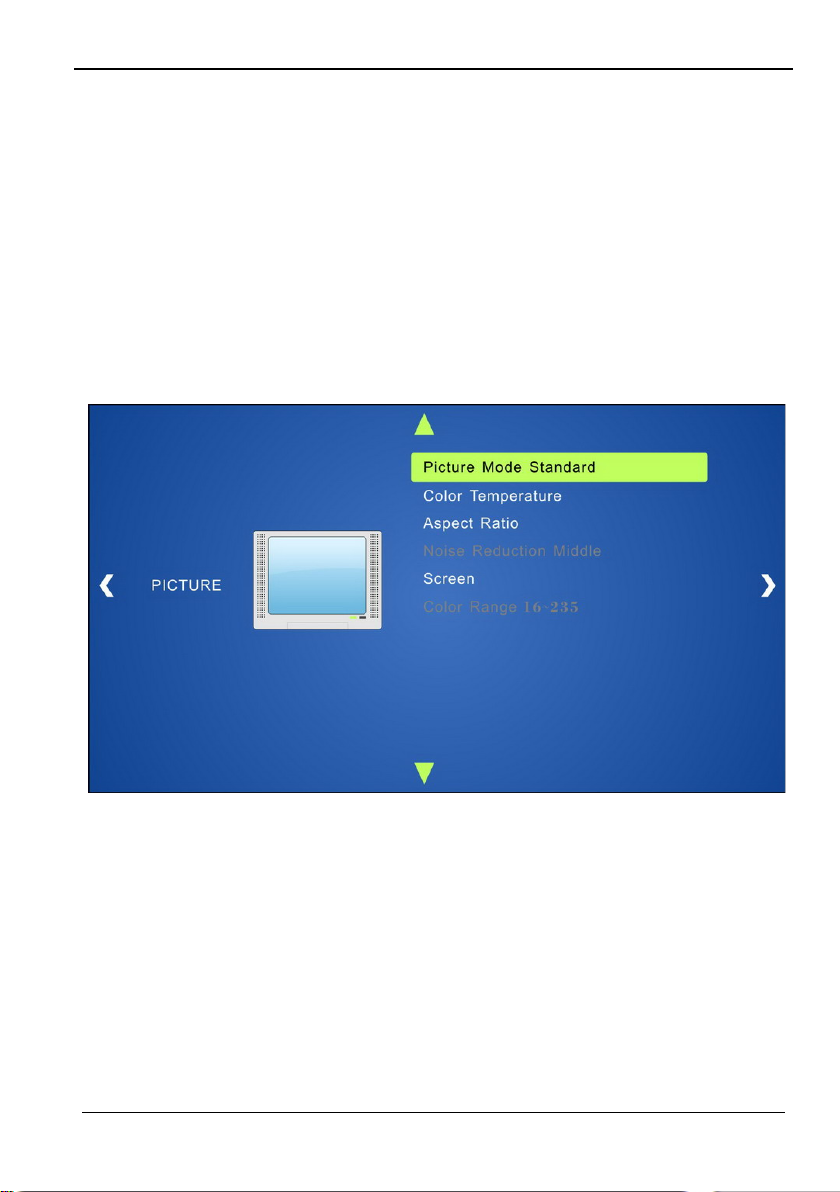
5.5.2 Picture
Includes Picture Mode, Color Temperature, Aspect Ratio, Noise Reduction, Screen and
Color Range
Picture mode: Includes Dynamic, Standard, Mild, and User. Only in User mode, will it
be able to set the image contrast, brightness, color a nd shar pnes s.
Color Temperature: Includes Cool, Medium, W arm and User mode. Only in User mode,
you can set values for Red, Green and Blue (RGB).
Aspect Ratio: Includes Native, 4:3, 16:9, Zoom1, Zoom2, Just Scan, and Panorama.
VGA format only supp or ts 4:3, 16:9 and Panorama.
Noise Reduction (not for VGA format): Includes Off, Low, Middle, High and Default.
Screen (not for HDMI s ource): Includes Auto Adjust, Horizontal, Vertical, Size, and
Phase.
Color Range (not for HDMI format): 16~235 or 0~255, use ENTER button to s elect the
desired color range.
© MuxLab Inc. 2015 32
Page 33
5x1 HDMI / HDBT Multimedia Presentation Switch Installation Guide
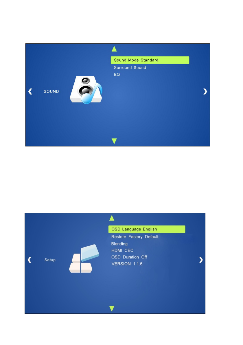
5.5.3 Sound
Includes Sound Mode, Surround Sound and EQ
Sound mode: Includes Standard, Music, Movie, Sports and User. Only in User
mode you can set treble and bass.
Surround Sound: Includes Off, Surround and SRS Trusurround XT.
EQ: To adjust the sound balance.
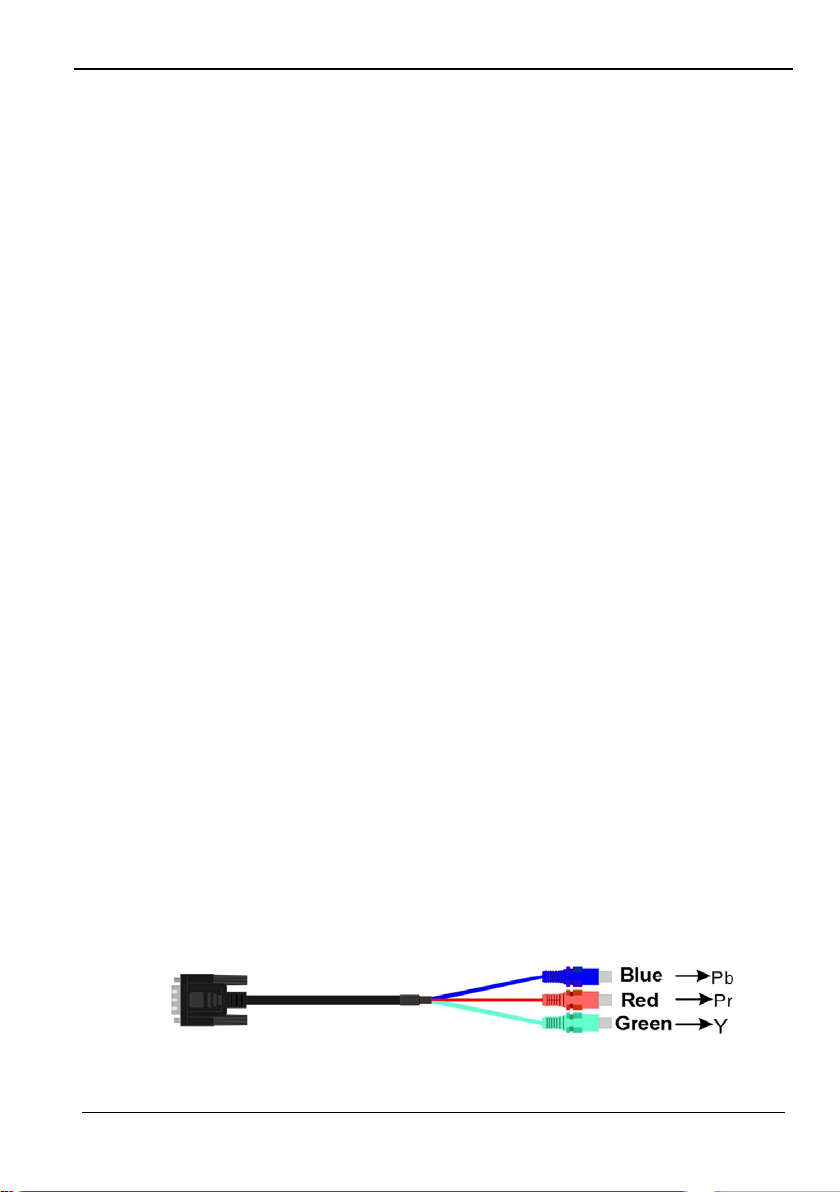
5.5.4 Setup
Includes OSD Language, Restore Factory Default, Blending, HDMI CEC, OSD Duration
and version inquiry
© MuxLab Inc. 2015 33
Page 34
5x1 HDMI / HDBT Multimedia Presentation Switch Installation Guide
OSD Language: Supports 7 languages, including English (default), Chines e etc.
Restore Factory Default: Restores to original system state .
Blending: Includes Low, Middle, High and Off. Use ENTER button to select.
HDMI CEC: Enable/disable CEC and auto-standby function. Default: CEC on,
STANDBY on. Only when CEC is on, will it be able to set auto-standby status.
OSD Duration: can be set to 5 s, 10 s, 15 s and Off. “s” is for Second.
VERSION: Displays software version.
5.6 Instructions of VGA Converting Cable
As VGA source supports YPbPr and Composite video source, the 500435 provides with
2 VGA converting cables to comply with these signals.
When you need to select these signals as input sources, please switch to channel
INPUT 4 or INPUT 5, and then set the signal type in the OSD menu. Then switch to
another input channel and connect INPUT 4 or INPUT 5 with corresponding source
device. Finally, switch to INPUT4 or INPUT 5 again.
Connect with Component Video (YPbPr) Source
There are three different ways to connect a Component Video source:
1. From the front panel buttons & OSD
Press the Menu button on the front panel to enter the OSD, and then enter the
OPTION setting menu: set “INPUT 4 Select” to YPbPr1, and “INPUT 5 Select” to
YPbPr2. Then, press Source/Auto button on the front pan el to switch to YPbPr1
or YPbPr2 source.
2. Via RS232 commands
Send command 50681% (or 50684%) to switch to YPbPr1 (or YPbPr2) source.
3. Via IR remote & OSD
Press Menu button on IR remo te to ent er the OSD menu, then enter the OPTION
setting menu: set “INPUT 4 Select” to YPbPr1, and “INPUT 5 Select” to YPbPr2.
After setting, press INPUT 4 (or INPUT 5) button to switch to YPbPr1 (or YPbPr2)
source.
The VGA cable used to convert the VGA signal to Component Video looks like this:
© MuxLab Inc. 2015 34
Page 35
5x1 HDMI / HDBT Multimedia Presentation Switch Installation Guide
Connect with Composite Video Source
There are three different ways to connect a Composite Video source:
1. From front panel buttons & OSD
Press the Menu button on the front panel to enter the OSD menu, then enter the
OPTION setting menu: set “INPUT 4 Select” to AV1, and “INPUT 5 Select” to
AV2. Finally, press Source/Auto button on the front p anel t o sw it ch to the AV1 or
the AV2 source.
2. Via RS232 commands
Send command 50682% (or 50685%) to switch to AV1 (or AV2) source.
3. Via IR remote & OSD
Press the Menu button on the IR remote to enter the OSD menu, then ent er the
OPTION setting menu: set “INPUT 4 Select” to AV1, and “INPUT 5 Select” to
AV2. Finally, press INPUT 4 (or INPUT 5) button to switch to AV1 (or AV2)
source.
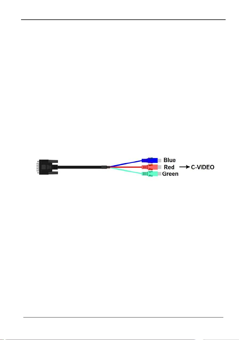
The VGA c able used to convert the VGA signal to Composite Video looks like this:
© MuxLab Inc. 2015 35
Page 36
5x1 HDMI / HDBT Multimedia Presentation Switch Installation Guide
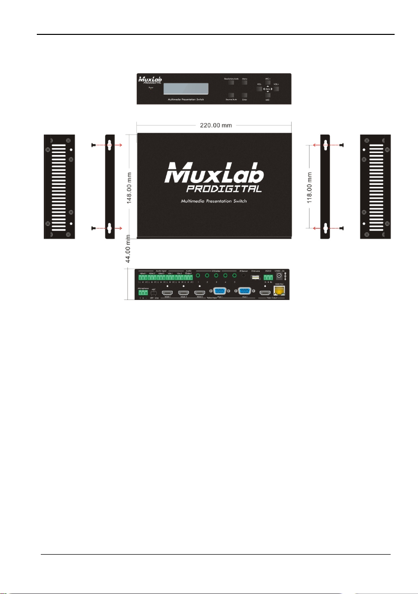
6. Panel Drawing
© MuxLab Inc. 2015 36
Page 37
5x1 HDMI / HDBT Multimedia Presentation Switch Installation Guide
Failed or loose
Make sure the connection is
Failed or loose connection
Make sure the connection is
POWER indicator doesn’t
Failed connection of power
Make sure the power cord
There is a blank screen
The display does not
Switch again.
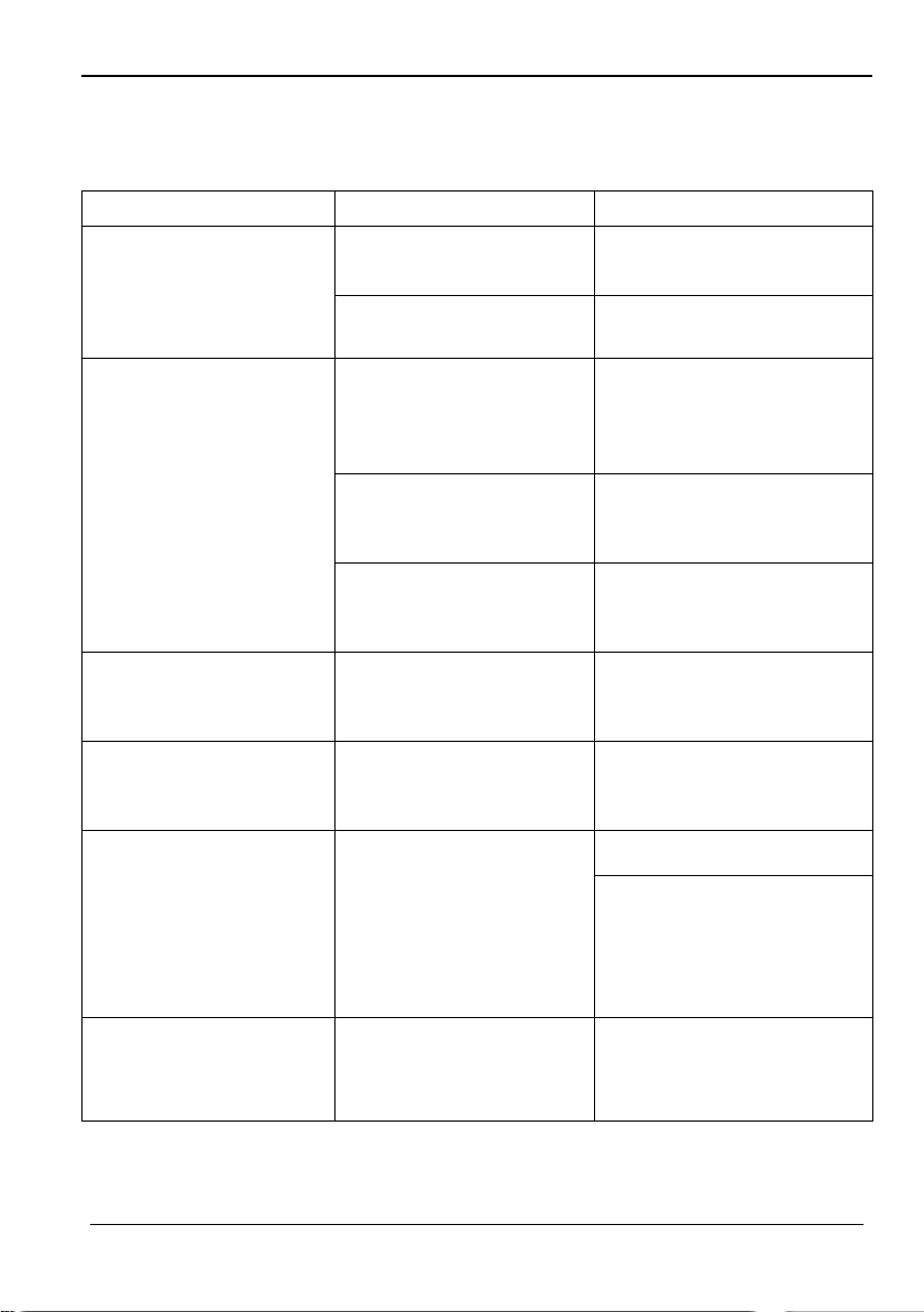
7. Troubleshooting & Maintenance
The following table describes some of the symptoms, probable causes and possible
solutions in respect to the installation of the 500435.
Problems Causes Solutions
Output image with
snowflakes
Bad quality of the
connecting cable
Try another high quality
cable.
No output image when
switching
work or doesn’t respond
to any operation
EDID management does
not work normally
on the display when
switching
connections
No signal at the input /
output end
The product is broken
cord.
The HDMI cable is broken
at the output end.
support the resolution of
the video source.
good
Check with oscilloscope or
multi-meter if there is any
signal at the input/ output
end.
good
Send it to authorized dealer
for repairing.
connection is good.
Change for another HDMI
cable which is in good
working condition.
Manage the EDID data
manually to make the
resolution of the video
source compliant with the
output resolution.
Static becomes stronger
when connecting the
video connectors
© MuxLab Inc. 2015 37
Bad grounding Check the grounding and
make sure it is well
connected.
Page 38
5x1 HDMI / HDBT Multimedia Presentation Switch Installation Guide
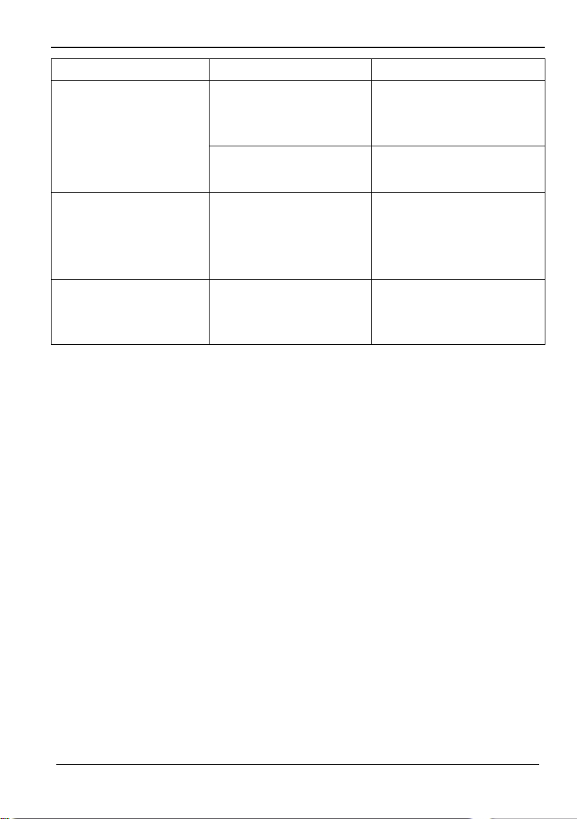
Problems Causes Solutions
Cannot control the device
through RS232 port
Wrong
RS232communication
parameters
Broken RS232 port Send it to authorized dealer
Type in
correctRS232communication
parameters
for checking.
Cannot control the
devicefrom thefront panel
buttons, but can control it
through RS232 port
Cannot control the device
by RS232, IR remote, or
front panel buttons
If you still cannot diagnose the problem, please call MuxLab Customer Technical
Support at 877-689-5228 (toll-free in North America) or (+1) 514-905-0588
(International).
The front panel buttons are
locked
The device has already
been broken.
Send command 50605% to
unlock the front panel
buttons.
Send it to authorized dealer
for repair.
© MuxLab Inc. 2015 38
Page 39

5x1 HDMI / HDBT Multimedia Presentation Switch Installation Guide
© MuxLab Inc. 2015 39
Page 40
5x1 HDMI / HDBT Multimedia Presentation Switch Installation Guide
E-mail: [email protected] URL: www.muxlab.com
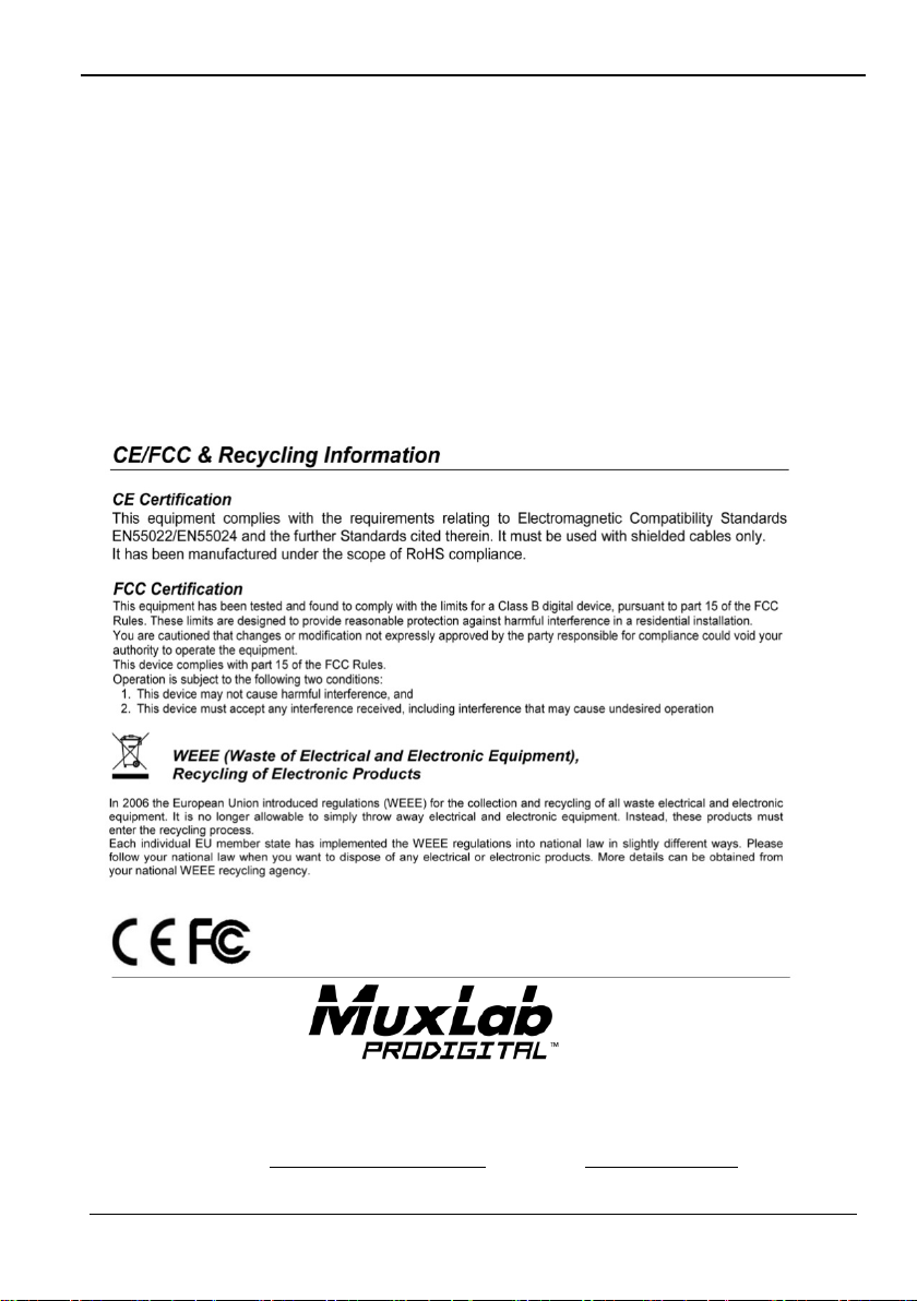
Regulatory Compliance
Disclaimer
Information in this document is subject to change without notice. The manufacturer does not make
any representations or warranties (implied or otherwise) regarding the accuracy and completeness
of this document and shall in no event be liable for any loss of profit or any ot her commercial
damage, including but not limited to special, incidental, consequential, or other damages.
No part of this document may be reproduced or transmitted in any form by any means, electronic or
mechanical, including photocopying, recording or information recording and retrieval systems
without the express written permission of the manufacturer.
All brand names and product names used in this document are trademarks, or registered
trademarks of their respective holders.
8495 Dalton Road, Mount Royal, Quebec, Canada. H4T 1V5
Tel: (514) 905-0588 Fax: (514) 905-0589
Toll Free (North America): (877) 689-5228
© MuxLab Inc. 2015 40
 Loading...