

Page 1
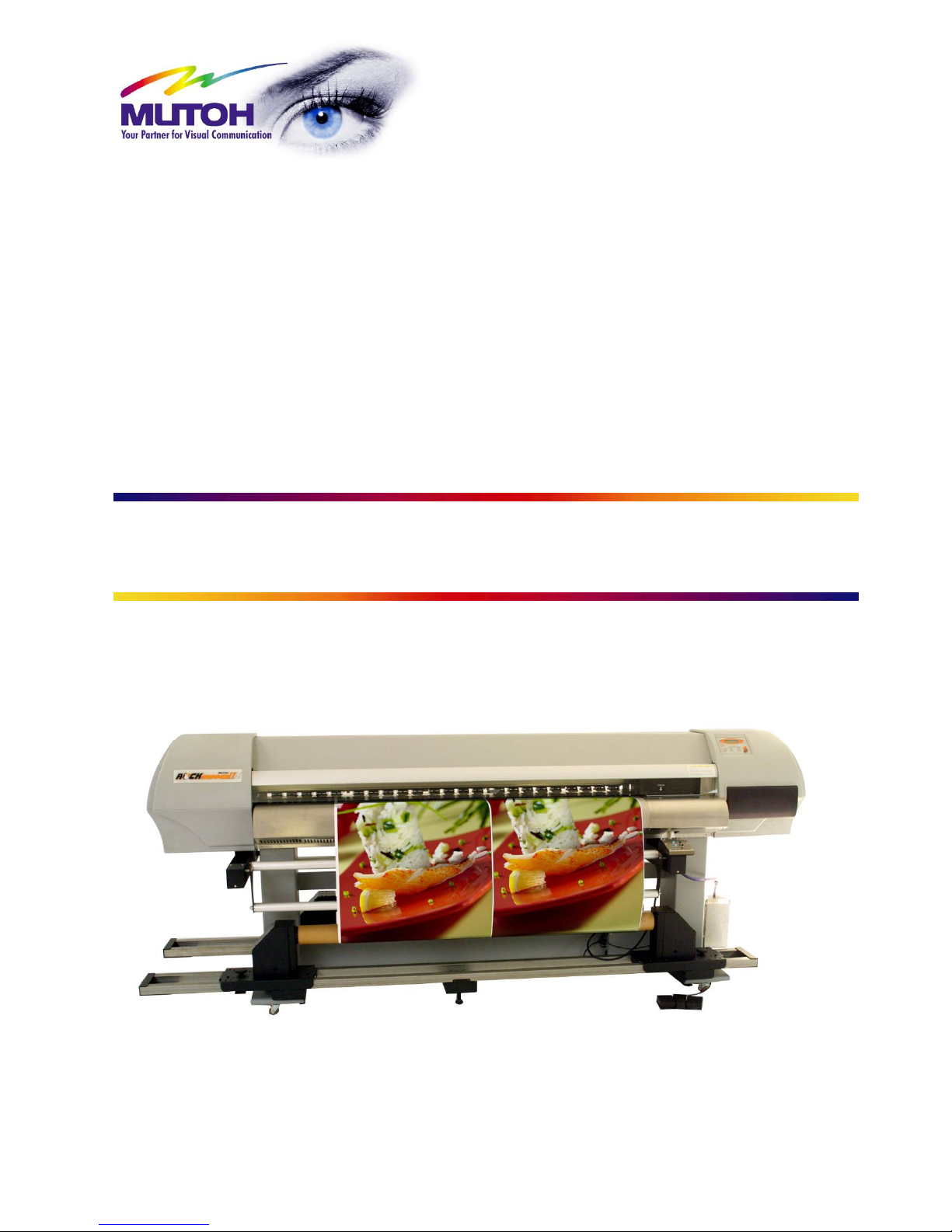
Mutoh’s Roll Systems
Unwinder / Winder 100
Winder 30
Maintenance Manual
MUTOH EUROPE N.V.
AP-74100, Rev : 2.0, 13/01/2005
Page 2

Roll systems – Maintenance Manual
2
AP-74100, Rev. 2.0, 12/01/05
Page 3

Roll systems – Maintenance Manual
3
AP-74100, Rev. 2.0, 12/01/05
COPYRIGHT NOTICE
COPYRIGHT © 2005 Mutoh Europe N.V. All rights reserved.
This document may not be reproduced by any means, in whole or in part, without written permission of the
copyright owner.
This document is furnished to support the Mutoh’s Unwinder / Winder 100, Unwinder 100 / Winder 30. In
consideration of the furnishing of the information contained in this document, the party to whom it is given,
assumes its custody and control and agrees to the following:
The information herein contained is given in confidence, and any part thereof shall not be copied or
reproduced without written consent of Mutoh Europe N.V.
This document or the contents herein under no circumstances shall be used in the manufacture or
reproduction of the article shown and the delivery of this document shall not constitute any right or license to
do so.
January 2005
Published: Mutoh Europe N.V., Archimedesstraat 13, B-8400 Oostende, BELGIUM
Page 4

Roll systems – Maintenance Manual
4
AP-74100, Rev. 2.0, 12/01/05
Page 5

Roll systems – Maintenance Manual
5
AP-74100, Rev. 2.0, 12/01/05
Important Notice
This product has been tested and found to comply with the limits for a Class A digital device, pursuant to Part
15 of FCC Rules. These limits are designed to provide reasonable protection against harmful interference
when the product is operated in a commercial environment.
This product generates, uses, and can radiate radio frequency energy and if not installed and used in
accordance with this manual, may cause harmful interference to radio communications. Operation of this
product in a residential area is likely to cause harmful interference in which case the user will be required to
correct the interference at his expense.
1. Radio interfere
Product generates weak radio signals and may interfere with television reception and utilities. If a
product does interfere with radio or TV reception, try following:
¾ Change the direction of your radio and TV reception antenna or feeder.
¾ Change the direction of the product.
¾ Move either the product or the receiving antenna so there is more distance between them.
¾ Be sure the product and the receiving antenna are on separate power lines.
2. Trademark mentioned in this manual.
¾ MUTOH is a registered trademark or product name of MUTOH INDUSTRIES LTD.
¾ Centronics and Bitronics are registered trademarks or product names of Centronics Data Computer
Corporation.
¾ Other company and product names may be registered trademarks or product names.
No part of this product or publication may be reproduced, copied or transmitted in any form or by any means,
except for personal use, without the permission of MUTOH EUROPE N.V.
The product and the contents of this publication may be changed without prior notification.
MUTOH EUROPE N.V. has made the best efforts to keep this publication free from error, but if you find any
uncertainties or misprints, please call us or the shop where you bought this equipment.
MUTOH EUROPE N.V. shall not be liable for any damages or troubles resulting from the use of this
equipment or this manual.
Page 6

Roll systems – Maintenance Manual
6
AP-74100, Rev. 2.0, 12/01/05
Page 7

Roll systems – Maintenance Manual
7
AP-74100, Rev. 2.0, 12/01/05
TABLE OF CONTENTS
1. SAFETY INSTRUCTIONS............................................................................................................................. 9
1.1. INTRODUCTION .........................................................................................................................................9
1.2. WARNINGS, CAUTIONS AND NOTE.............................................................................................................. 9
1.3. IMPORTANT SAFETY INSTRUCTIONS............................................................................................................ 9
1.4. WARNING LABELS ................................................................................................................................... 10
2. PRODUCT OVERVIEW................................................................................................................................11
2.1. INTRODUCTION .......................................................................................................................................11
2.2. PART NAMES AND FUNCTIONS.................................................................................................................. 11
2.2.1. Unwinder / Winder 100.................................................................................................................................. 11
2.2.2. Operation panel unwinder/winder 100...........................................................................................................12
2.2.3 Winder 30 .......................................................................................................................................................13
2.2.4. Operation Panel Winder 30 ...........................................................................................................................14
2.2.5. Unwinder 100.................................................................................................................................................15
2.2.6. Operation Panel Unwinder 100...................................................................................................................... 16
3. PARTS REPLACEMENT ............................................................................................................................ 17
3.1. INTRODUCTION .......................................................................................................................................17
3.2. REMOVAL ON THE OPERATION PANEL ....................................................................................................... 18
3.2.1. Replace the operation panel cover................................................................................................................18
3.2.2. Replace the operation panel PCB box...........................................................................................................19
3.2.3. Connecting the PCB board operation panel with the operation panel............................................................20
3.3. REMOVAL OF THE PCB BOX OF THE UNWINDER/WINDER 100..................................................................... 21
3.3.1. How to replace the power supply board.........................................................................................................21
3.3.2. How to replace the PCB board of the PCB box .............................................................................................23
3.3.3. How to replace the power supply connector..................................................................................................24
3.3.4. Connections in the PCB box..........................................................................................................................26
3.4 REMOVAL OF THE PCB BOX OF THE WINDER 30......................................................................................... 27
3.5. REMOVAL ONTO THE TENSIONING SYSTEM ................................................................................................ 29
3.5.1 Replacing the sensor assy..............................................................................................................................29
3.5.2 Connecting the sensors..................................................................................................................................31
3.6. REMOVALS ONTO THE ROLL UNIT ............................................................................................................. 32
3.6.1. Replacing the core cone of the roll unit..........................................................................................................32
3.6.2. Replacing the core cone of the motorized roll unit.........................................................................................33
3.6.3. Replacing the motor in the motorized roll unit................................................................................................ 34
3.6.4. Connecting the motor ....................................................................................................................................35
3.7 REPLACEMENT OF THE SCROLLER ASSEMBLY ............................................................................................ 36
3.7.1. Replacing the scroller R assembly.................................................................................................................36
3.7.2. Replacing the scroller L assembly.................................................................................................................37
4. ADJUSTMENTS.......................................................................................................................................... 39
4.1. SENSOR (TENSION BAR) ADJUSTMENT UNWINDER/WINDER 100.................................................................. 39
(ONLY APPLICALBE FOR SYSTEMS MANUFACTURED BEFORE YEAR 2005)......................................................... 39
4.1.1. Understanding the principles of the sensors..................................................................................................39
4.1.2. Adjust the sensors of the front tensioning bar................................................................................................40
4.1.3. Adjust the sensors of the rear tensioning bar ................................................................................................42
4.1.4. Sensor disc and adjustment direction............................................................................................................45
4.1.5. Angle mark front tensioning system...............................................................................................................46
4.1.6. Stop Sensor Position..................................................................................................................................... 46
4.1.7. Start Sensor Position.....................................................................................................................................47
4.2. SENSOR (TENSION BAR) ADJUSTMENT UNWINDER 100 / WINDER 30........................................................... 48
(ONLY APPLICALBE FOR SYSTEMS MANUFACTURED BEFORE YEAR 2005)......................................................... 48
4.2.1. Understanding the principles of the sensors..................................................................................................48
4.2.2. Adjust the sensors of the rear tensioning bar ................................................................................................49
4.2.3. Sensor disc and adjustment direction............................................................................................................51
4.2.4. Stop Sensor Position..................................................................................................................................... 51
4.2.5. Start Sensor Position.....................................................................................................................................52
4.3 CALIBRATION OF THE UNWINDER 100 AND WINDER 100.............................................................................. 53
4.3.1 Calibration of the rear tensioning system........................................................................................................53
4.3.2 Calibration of the front and rear roll unit..........................................................................................................56
Page 8

Roll systems – Maintenance Manual
8
AP-74100, Rev. 2.0, 12/01/05
5. APPENDIX................................................................................................................................................... 59
5.1. INTRODUCTION .......................................................................................................................................59
5.2. WIRING DIAGRAM ................................................................................................................................... 59
5.3. EXPLODED VIEWS................................................................................................................................... 60
5.3.1 Assembling unwinder/winder 100................................................................................................................... 61
5.3.2 Assembling unwinder 100/winder 30..............................................................................................................78
5.3.3 Unwinder 30 ...................................................................................................................................................99
Page 9
Roll systems – Maintenance Manual
9
AP-74100, Rev. 2.0, 12/01/05
1. SAFETY INSTRUCTIONS
1.1. INTRODUCTION
This chapter explains the meaning of safety terms for personnel who operate this equipment and important
safety instructions.
Important :
• Be sure to follow all instructions and warnings in this manual when using the
equipment.
1.2. WARNINGS, CAUTIONS AND NOTE
Safety terms in this manual and the contents of warning labels attached to the printer are categorized into
the following three types depending on the degree of risk (or the scale of accident ).
Read the following explanations carefully, and follow the instructions in this manual.
Safety terms Details
Important Must be followed carefully to avoid death or serious bodily injury.
Caution Must be observed to avoid bodily injury (moderately or lightly) or damage to your
equipment.
Note Contains important information and useful tips on the operation of your printer.
1.3. IMPORTANT SAFETY INSTRUCTIONS
General safety instructions that must be observed to use the equipment safely are explained below.
¾ Do not stand on or place heavy objects on the unit. Doing so may result in the unit tipping or
falling over and causing injury.
¾ Do not attempt to plug in electrical plugs with wet hands. Doing so may result in electrical shock.
¾ Do not use thinner, benzene, alcohol or other active agents. Doing so may result in damage or
paint peeling from the casing.
¾ Be careful not to spill water inside the printer. Doing so may result in a short circuit.
¾ Never open the covers fixed with screws. Doing so may result in electrical shock or a
malfunctioning in the unit.
¾ When setting roll media, place it on top of a desk or other flat surface. Setting roll media with the
scroller standing up may damage them.
Page 10
Roll systems – Maintenance Manual
10
AP-74100, Rev. 2.0, 12/01/05
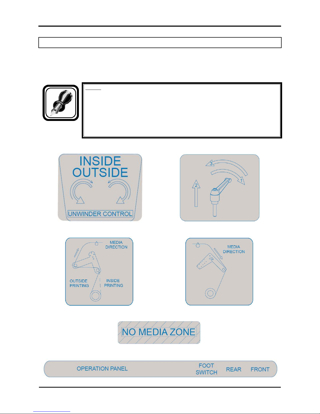
1.4. WARNING LABELS
The handling, attachment locations and types of warning labels are explained below.
Warning labels are attached on areas which require attention. Read and understand the po sitions and
contents thoroughly before performing your work.
Be sure to note the following when handling the labels.
Notes :
• Make sure that all labels can be recognized. If text or illustrations cannot be seen
clearly, either clean or replace the label.
• When cleaning labels, use a cloth with water or neutral detergent. Do not use a
solvent or gasoline.
• If a warning label is damaged, lost, or cannot be recognized, replace the label.
When replacing warning labels, contact your local MUTOH dealer.
Foot switch label unwinder 100
Roll unit handle label unwinder 100
Rear tensioning label unwinder 100
Front tensioning label unwinder 100
Paper guide label unwinder 100
PCB box label unwinder
Page 11

Roll systems – Maintenance Manual
11
AP-74100, Rev. 2.0, 12/01/05
2. PRODUCT OVERVIEW
2.1. INTRODUCTION
This chapter explains the features, part names and functions of the printer.
2.2. PART NAMES AND FUNCTIONS
Part names and functions are explained below.
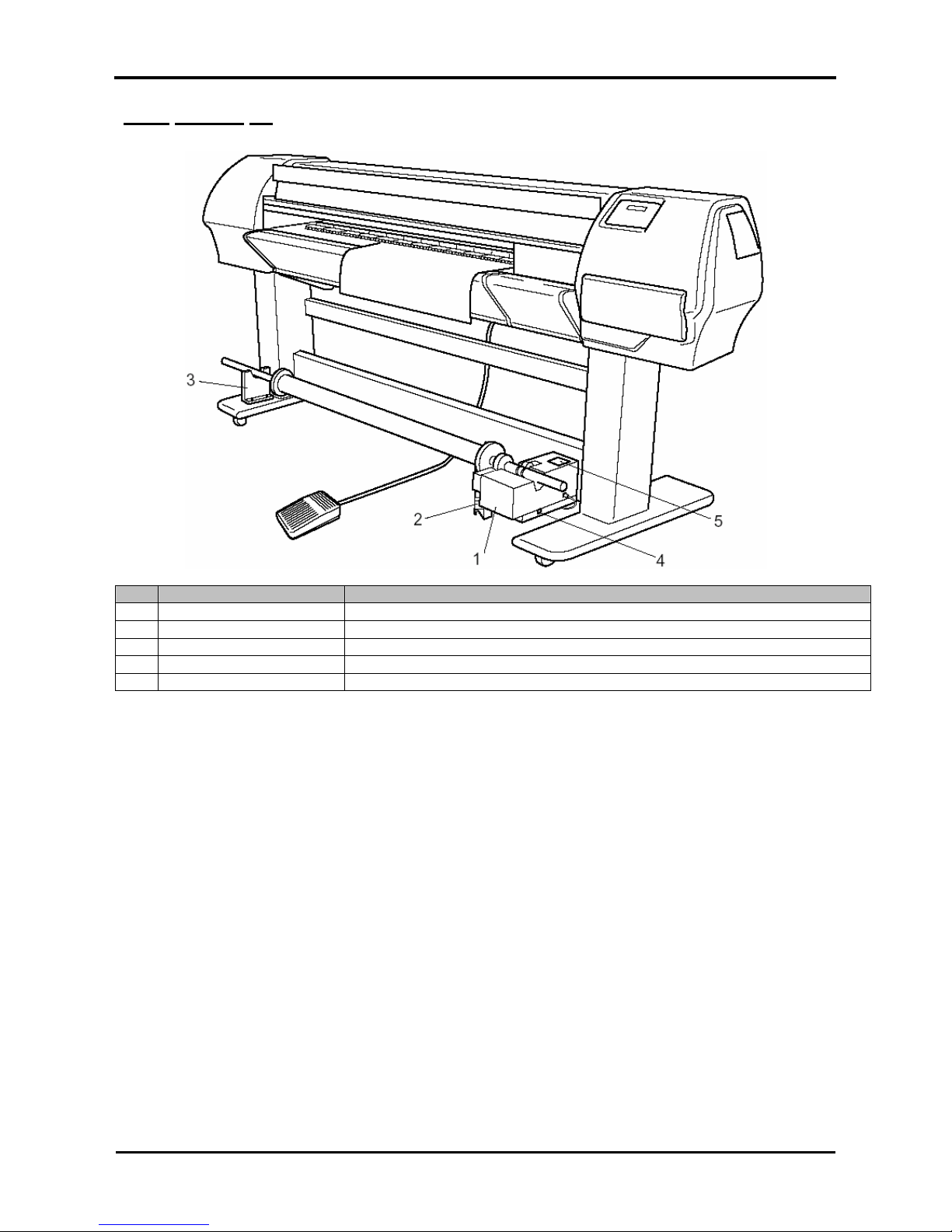
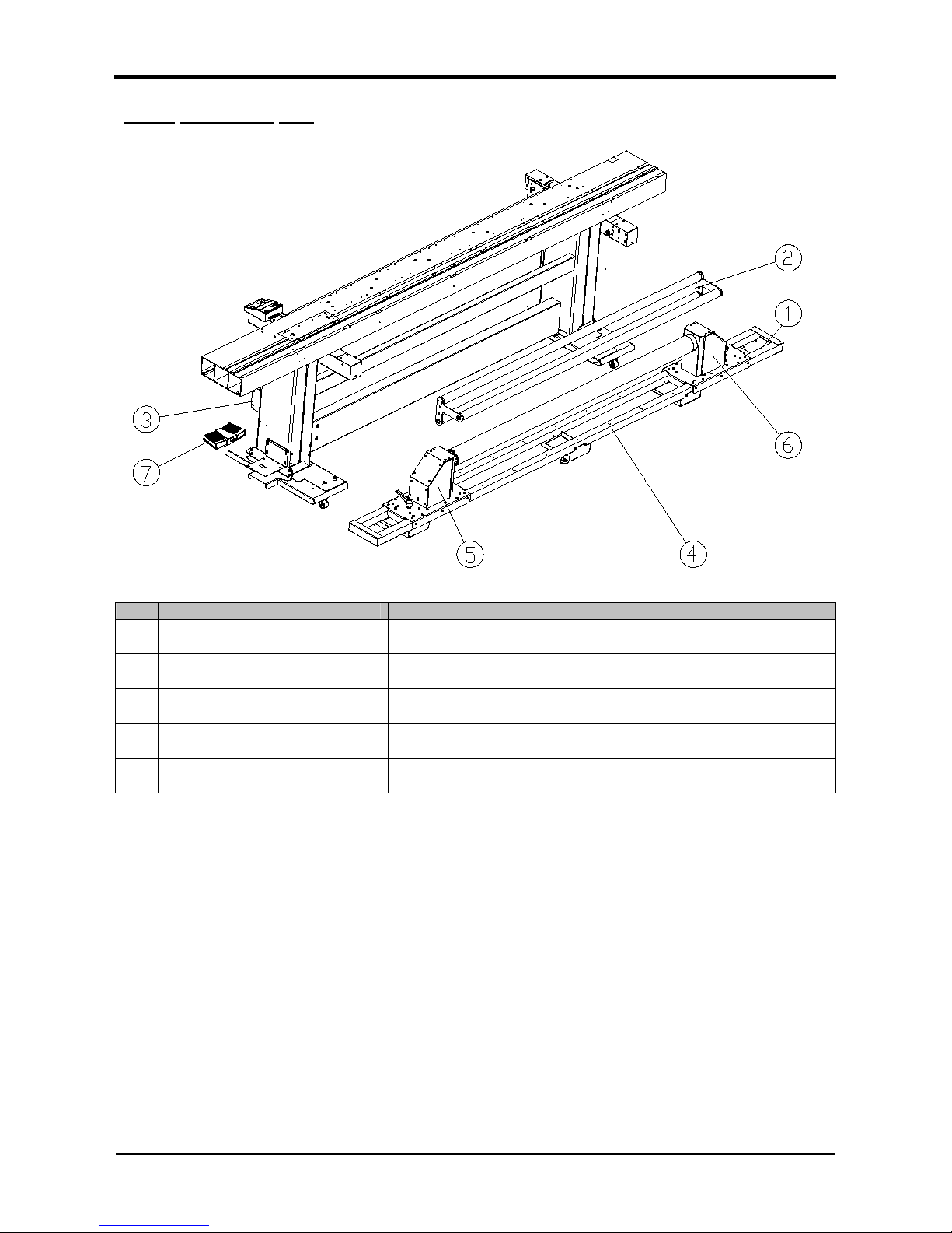
2.2.1. Unwinder / Winder 100
Part names and functions are explained below.
No. Name Function
1 Roll-Off System This is the device that sets the media when using roll media and feeds it to
the printing position.
2 Rear Tension system Adjust the tension of the media between the roll-off system and the media
feed slot.
3 PCB Box Contains the boards to control the unwinder / winder 100.
4 Rail Assembly Carries the roll units.
5 Motorized roll unit Supports the roll media.
6 Roll unit Supports the roll media.
7 Roll-off foot switch This switch is used to roll-up or roll-off roll media of the unwinder 100.
8 Front Tension System Adjust the tension of the media between the paper guide and the roll-up
system.
9 Roll-Up System This is the device that collects the media when using roll media.
10 Operation Panel This panel is used to set operational conditions, and the status of the product.
Page 12

Roll systems – Maintenance Manual
12
AP-74100, Rev. 2.0, 12/01/05
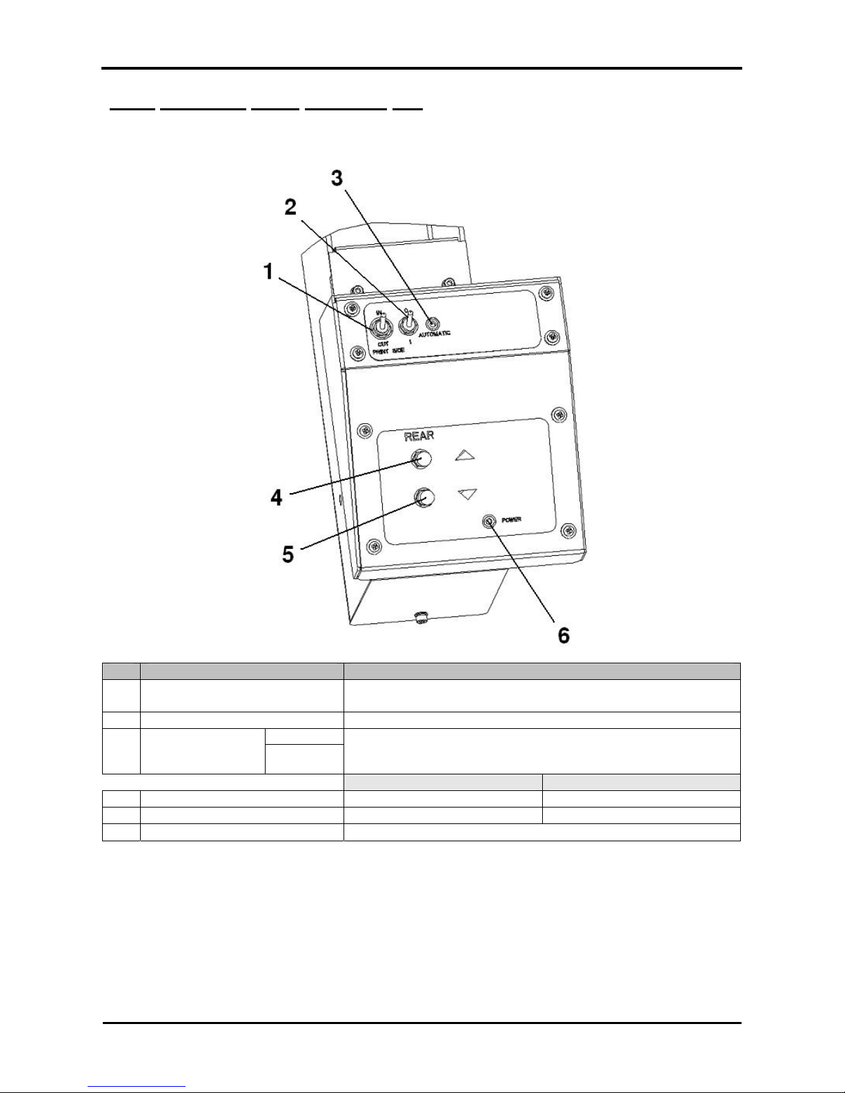
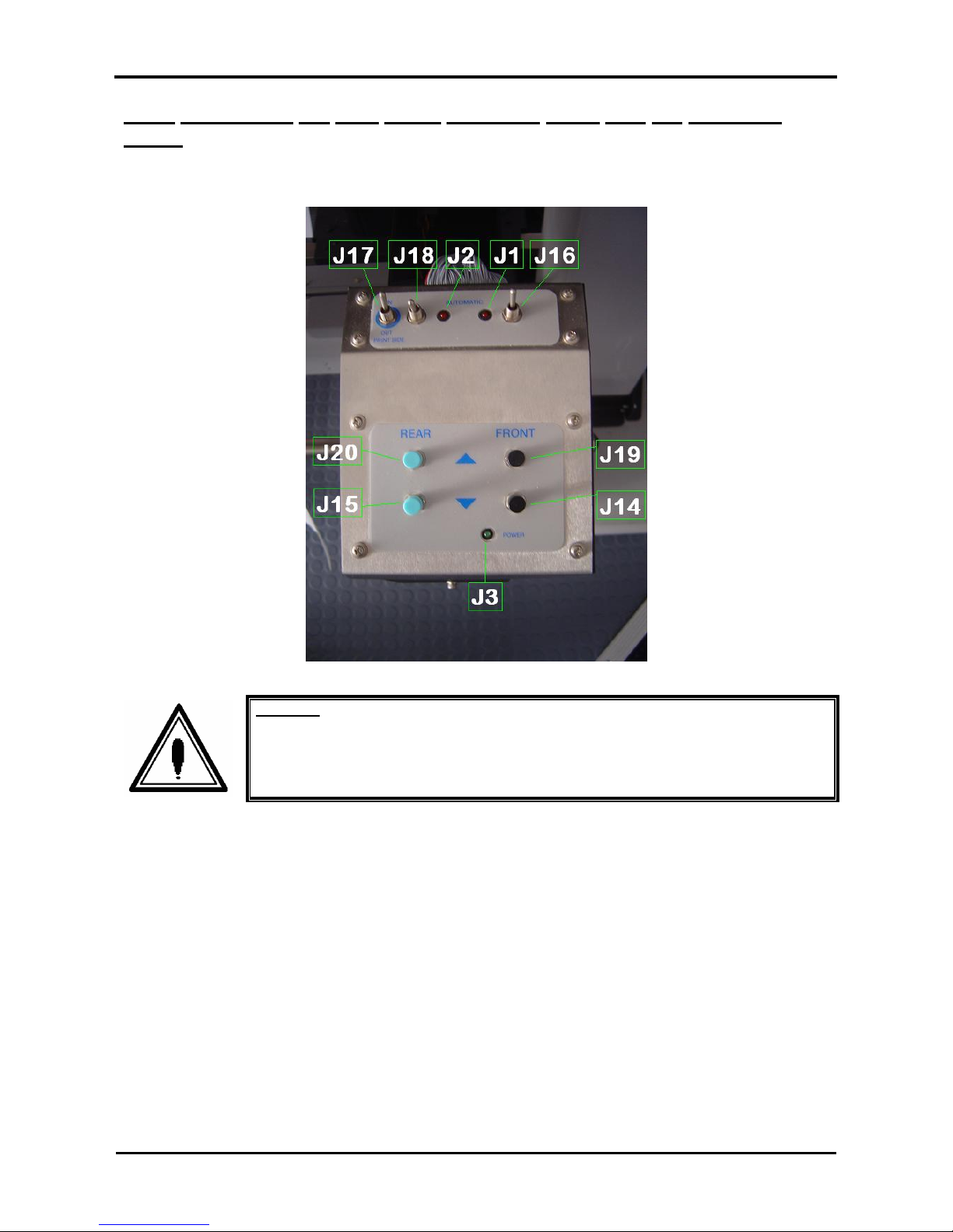
2.2.2. Operation panel unwinder/winder 100
The operation panel is used to set operational conditions.
No. Name Function
A / Part of the operation panel controlling the unwinder 100.
B / Part of the operation panel controlling the winder 100.
1 Print Side Selector
In case you loaded media with printed side on the outside select
‘OUT’, otherwise select ‘IN’.
2 Unwinder 100 power ON Toggle between Manual and Automatic mode.
Manual
3 Unwinder 100 LED
Automatic
LED lights up when pushing one of the buttons
Motor turns: LED flashes.
Motor is off : LED is out.
Outside printing Inside printing
4 Backwards button Roll-off unwinder Roll-up unwinder
5 Forwards button Roll-up unwinder Roll-off unwinder
6 Winder 100 power ON Power ON or OFF the winder 100.
Manual
7 Winder 100 LED
Automatic
LED lights up when pushing one of the buttons
Motor turns: LED flashes
Motor is off: LED is out.
Outside printing Inside printing
8 Backwards button Roll-off winder Roll-off winder
9 Forwards button Roll-up winder Roll-up winder
10 Power LED Lightens up the system is powered ON.
Page 13
Roll systems – Maintenance Manual
13
AP-74100, Rev. 2.0, 12/01/05
2.2.3 Winder 30
No. Name Function
1 Winder 30 motorized unit Winds and collects the printed roll media.
2 Media sensor Detects the printed media.
3 Scroller receiver Loads the scroller for the winding unit.
4 Power switch Turn the product ON and OFF.
5 Operation Panel This panel is used to set operational conditions, and the status of the product.
Page 14

Roll systems – Maintenance Manual
14
AP-74100, Rev. 2.0, 12/01/05
2.2.4. Operation Panel Winder 30
The operation panel is used to set operational conditions and to check / display the status of the product.
(1) Operation switches
No. Name Function
1 AUTO switch Used to automatically wind the roll media.
→ Forward : When the media sensor detects the media, the
scroller automatically rotates forward. The media is wound with
the printed side at the outside.
→ OFF : Used when operating the MANUAL switch.
→ Backward : When the media sensor detects the media, the
scroller automatically rotates backward. The media is wound with
the printed side at the inside.
2 MANUAL switch The winder system is manually operated.
→ Forward : The scroller rotates forward.
→ Backward : The scroller rotates backward.
(2) Status Lamp
No. Name Status Function
ON The product is ON.
Waiting
Flashing An error has occurred.
3 SENSOR lamp
OFF The product is winding the media.
The product is OFF.
Page 15
Roll systems – Maintenance Manual
15
AP-74100, Rev. 2.0, 12/01/05
2.2.5. Unwinder 100
No. Name Function
1 Roll-Off System This is the device that sets the media when using roll media and
feeds it to the printing position.
2 Rear Tension system Adjust the tension of the media between the roll-off system and
the media feed slot.
3 PCB Box Contains the boards to control the unwinder 100.
4 Rail Assembly Carries the roll units.
5 Motorized roll unit Supports the roll media.
6 Roll unit Supports the roll media.
7 Roll-off foot switch This switch is used to roll-up or roll-off roll media of the unwinder
100.
Page 16
Roll systems – Maintenance Manual
16
AP-74100, Rev. 2.0, 12/01/05
2.2.6. Operation Panel Unwinder 100
The operation panel is used to set operational conditions.
No. Name Function
1 Print Side Selector
In case you loaded media with printed side on the outside select
‘OUT’, otherwise select ‘IN’.
2 Unwinder 100 power ON Toggle between Manual and Automatic mode.
Manual
3 Unwinder 100 LED
Automatic
LED lights up when pushing one of the buttons
Motor turns: LED flashes.
Motor is off : LED is out.
Outside printing Inside printing
4 Backwards button Roll-off unwinder Roll-up unwinder
5 Forwards button Roll-up unwinder Roll-off unwinder
6 Power LED Lightens up once the system is powered ON
Page 17
Roll systems – Maintenance Manual
17
AP-74100, Rev. 2.0, 12/01/05
3. PARTS REPLACEMENT
3.1. INTRODUCTION
This chapter explains the procedures for replacing and removing maintenance parts.
Important :
¾ Before replacing parts, be sure to perform following operations.
Turn the power off. Make sure the printer is also powered off.
Remove the electrical cable from the socket. Otherwise, you may
suffer electric shock or the machine’s electric circuits may be
damaged.
Disconnect all cables from the machine. Not doing so could cause
damage to the printer.
Caution :
¾ Assembling and disassembling the unit are possible only for the parts for which
disassembling procedures are shown in the operation manual.
¾ Do not disassemble any frame parts or parts for which disassembling procedures
are not shown in the manual.
¾ Doing so may cause trouble that cannot be restored, as the unit is originally
assembled in the factory with a high accuracy of 1/100 mm.
Caution :
• In case you have replaced the front and/or rear media guide, always perform a
calibration of the front tensioning system and the roll-up systems. Because the new
media guide can have a slight different shape, thickness…
Notes :
¾ After replacing the parts, perform the adjustment of the unwinder / winder 100 as
described in the User’s Guide.
Page 18

Roll systems – Maintenance Manual
18
AP-74100, Rev. 2.0, 12/01/05
3.2. REMOVAL ON THE OPERATION PANEL
3.2.1. Replace the operation panel cover.
Step 1 : Remove the eight screws fixing the operation panel.
Caution :
Be sure not to damage the cables nor the connectors.
Step 2 : Carefully loosen the connectors.
Step 3 : Remove the operation panel.
Page 19
Roll systems – Maintenance Manual
19
AP-74100, Rev. 2.0, 12/01/05
3.2.2. Replace the operation panel PCB box
Step 1 : Remove the operation panel.
Step 2 : Loosen the sensor cables.
Step 3 : Remove the parallel connector cable.
Step 4 : Loosen the two screws fixing the parallel connector.
Step 5 : Loosen the four screws fixing the operation panel PCB box.
Step 6 : Remove the operation panel PCB box.
Page 20
Roll systems – Maintenance Manual
20
AP-74100, Rev. 2.0, 12/01/05
3.2.3. Connecting the PCB board operation panel with the operation
panel.
Connections at the operation panel are:
Caution :
Be sure not to damage the cables nor the connectors.
Page 21
Roll systems – Maintenance Manual
21
AP-74100, Rev. 2.0, 12/01/05
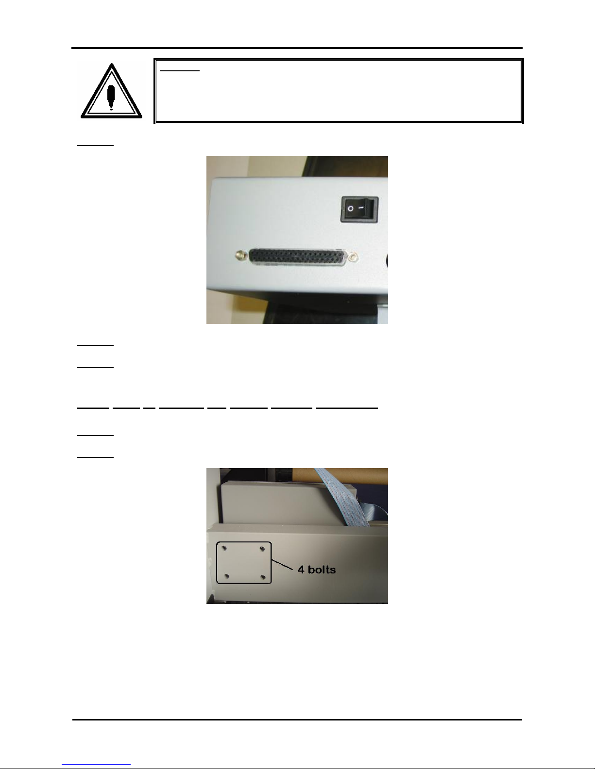
3.3. REMOVAL OF THE PCB BOX OF THE UNWINDER/WINDER
100
Important :
Before replacing parts, be sure to perform the following operations.
¾ Turn the machine power OFF.
¾ Remove the product's electrical plug from the socket. Otherwise, you may
suffer electric shock or the machine’s electric circuits may be damaged.
¾ Disconnect all cables from the machine. Not doing so could cause damage to
the printer.
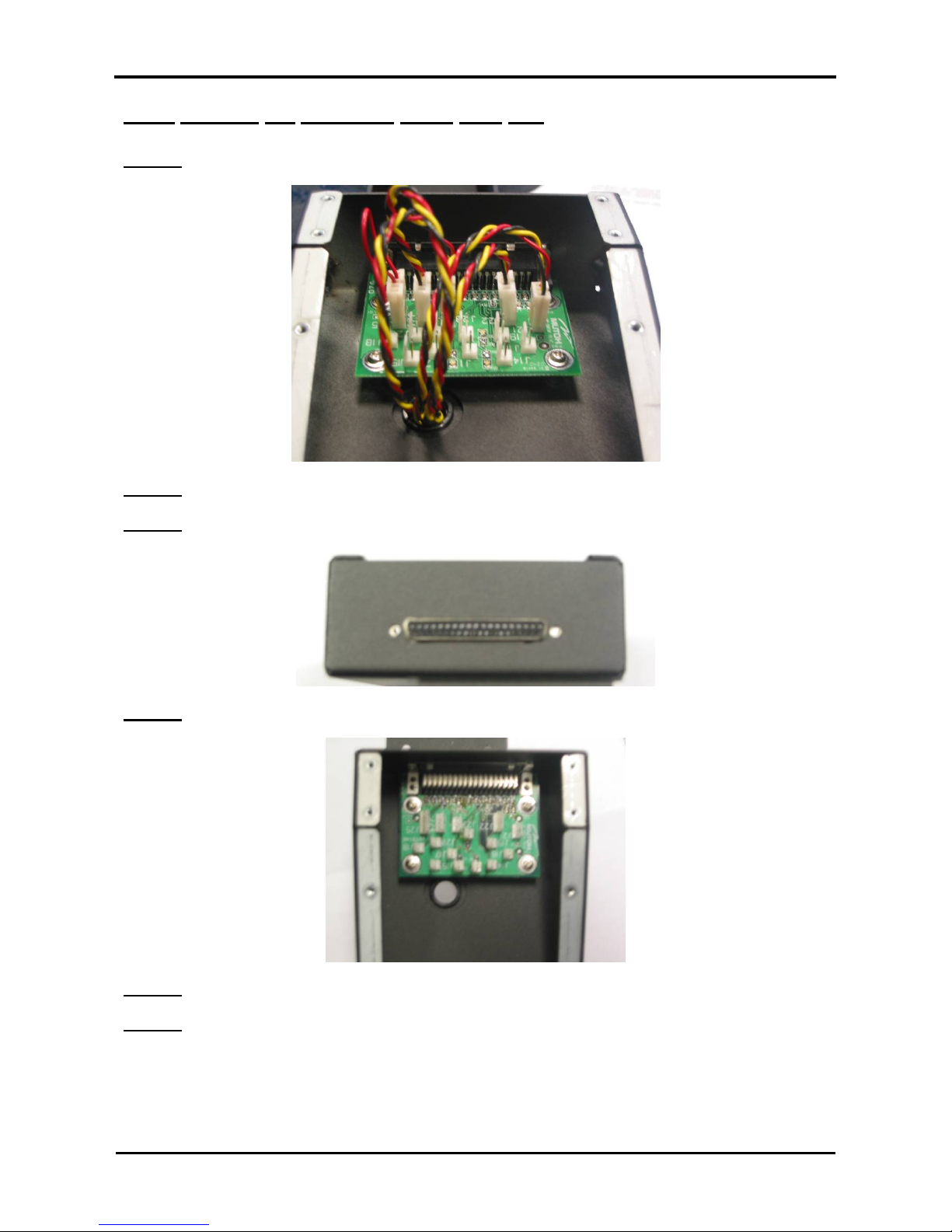
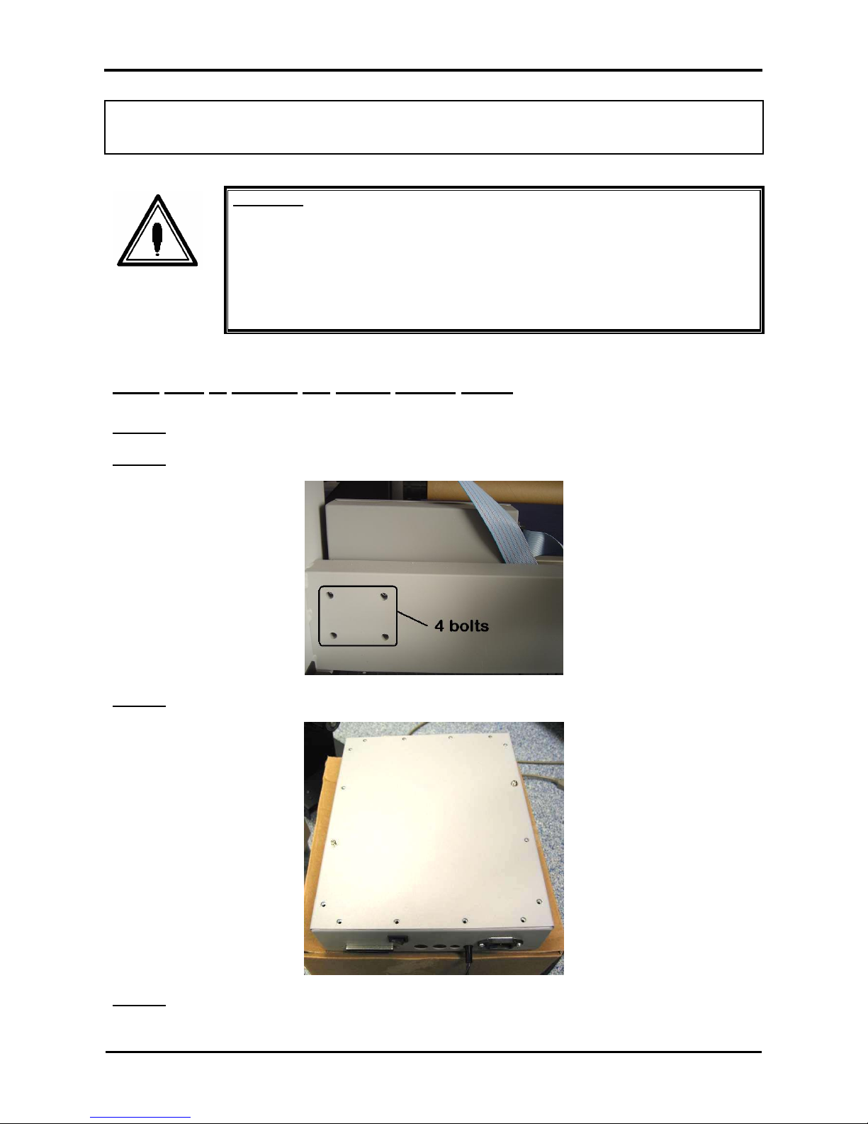
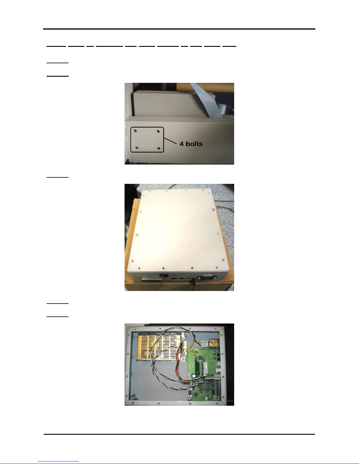
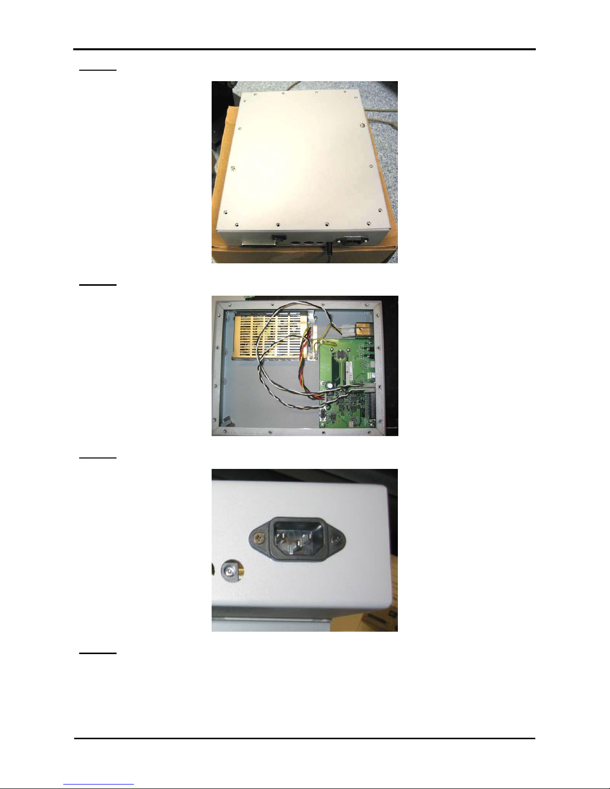
3.3.1. How to replace the power supply board
Step 1 : Remove all connectors from the PCB box.
Step 2 : Remove the PCB box from the beam.
Step 3 : Loosen the 16 screws fixing the cover of the PCB box.
Step 4 : Remove the cover of the PCB box.
Page 22
Roll systems – Maintenance Manual
22
AP-74100, Rev. 2.0, 12/01/05
Step 5 : Remove the connectors.
Caution :
Be sure not to damage the cables nor the connectors.
Step 6 : Remove the four screws fixing the power supply board.
Step 7 : Remove the power supply board.
Page 23
Roll systems – Maintenance Manual
23
AP-74100, Rev. 2.0, 12/01/05
3.3.2. How to replace the PCB board of the PCB box
Step 1 : Remove all connectors from the PCB box.
Step 2 : Remove the PCB box from the beam.
Step 3 : Loosen the 16 screws fixing the cover of the PCB box.
Step 4 : Remove the cover of the PCB box.
Step 5 : Remove the connectors.
Page 24
Roll systems – Maintenance Manual
24
AP-74100, Rev. 2.0, 12/01/05
Caution :
Be sure not to damage the cables nor the connectors.
Step 6 : Remove the two screws fixing the parallel connector.
Step 7 : Remove the six screws fixing the PCB board.
Step 8 : Remove the PCB board.
3.3.3. How to replace the power supply connector
Step 1 : Remove all connectors from the PCB box.
Step 2 : Remove the PCB box from the beam.
Page 25
Roll systems – Maintenance Manual
25
AP-74100, Rev. 2.0, 12/01/05
Step 3 : Loosen the 16 screws fixing the cover of the PCB box.
Step 4 : Remove the cover of the PCB box.
Step 5 : Remove the two screws fixing the power supply connector.
Step 6 : Remove the power supply connector
Page 26
Roll systems – Maintenance Manual
26
AP-74100, Rev. 2.0, 12/01/05
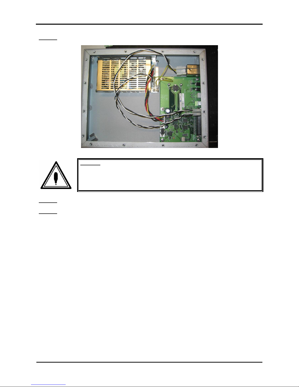
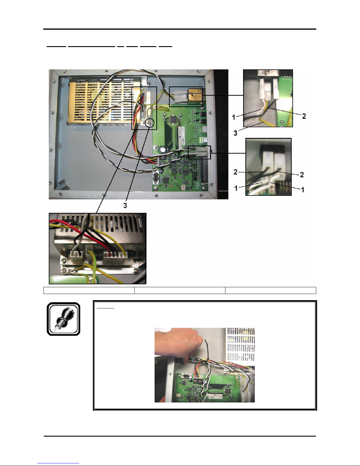
3.3.4. Connections in the PCB box
Please connect as shown in the picture below.
1 = white 2 = black 3 = green/yellow (grounding)
Notes :
¾ Please make sure to fix the cables together by using the cable clamp.
Page 27
Roll systems – Maintenance Manual
27
AP-74100, Rev. 2.0, 12/01/05
3.4 REMOVAL OF THE PCB BOX OF THE WINDER 30
To replace the PCB board, please follow the steps mentioned below:
Step 1 : Remove the five screws of the top cover of the take-up system and disconnect the power supply
cable.
No. Part
1 Top cover screws
2 Power supply cable
Step 2 : Remove the two screws of the switch board and disconnect the black flat cable connected to the
PCB board.
No. Part
1 Switch board attaching screws
Page 28

Roll systems – Maintenance Manual
28
AP-74100, Rev. 2.0, 12/01/05
Step 3 : Remove the screw and 3 spacers of the PCB board.
No. Part
1 Spacers
2 Screw
Step 4 : Replace the PCB board by a new one (EY-80579).
Step 5 : To re-install the removed components, reverse the removal procedure.
Page 29

Roll systems – Maintenance Manual
29
AP-74100, Rev. 2.0, 12/01/05
3.5. REMOVAL ONTO THE TENSIONING SYSTEM
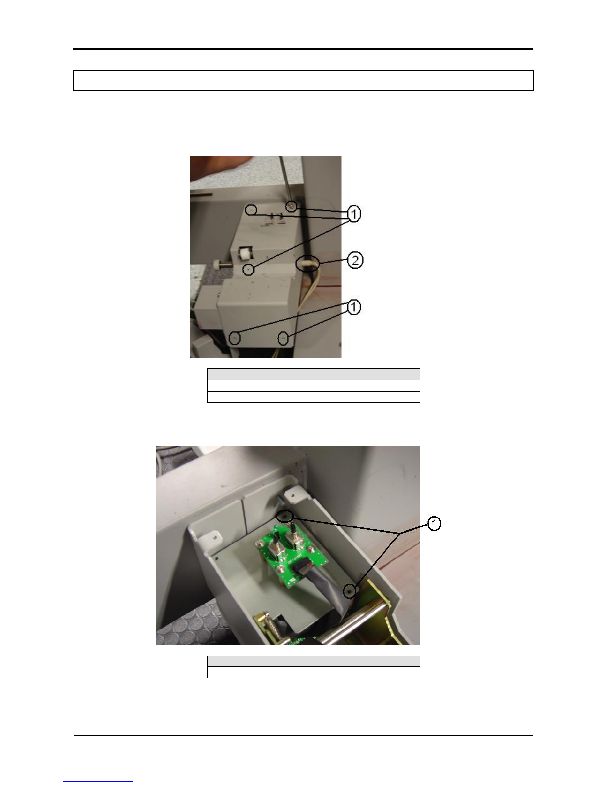
3.5.1 Replacing the sensor assy
Step 1 : Disconnect the power cable of the operation panel.
Step 2 : Loosen the three screws fixing the cover of the tensioning sensor bracket.
Step 3 : Remove the cover.
Step 4 : Loosen the connectors.
Caution :
Be sure not to damage the cables nor the connectors.
Step 5 : Loosen the two screws fixing the sensor bracket.
Page 30
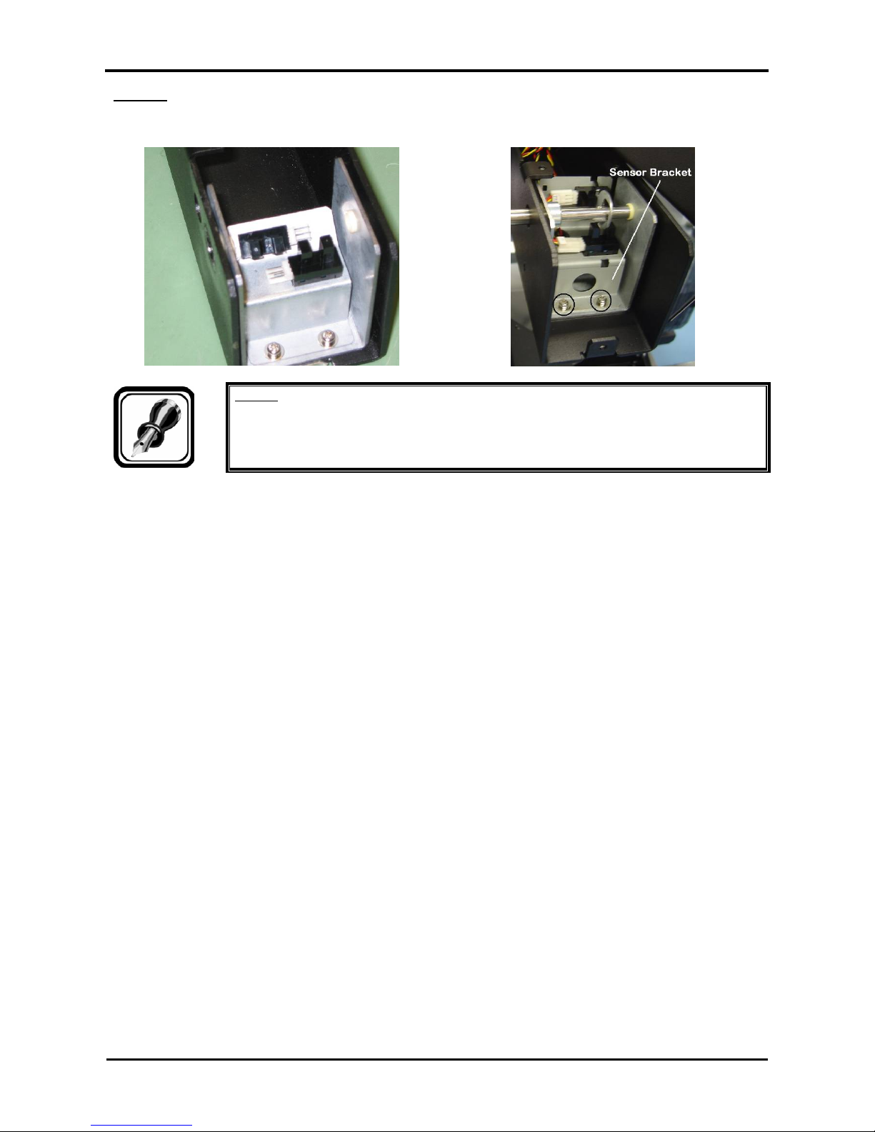
Roll systems – Maintenance Manual
30
AP-74100, Rev. 2.0, 12/01/05
Step 6 : Remove the sensor bracket.
Before manufacturing date 2005 As from manufacturing date 2005
Notes :
¾ Repeat the steps above to remove the rear side sensor bracket.
Page 31

Roll systems – Maintenance Manual
31
AP-74100, Rev. 2.0, 12/01/05
3.5.2 Connecting the sensors
Please find below the connections of the sensors in the tensioning system.
Before manufacturing date 2005
As from manufacturing date 2005
No Part
Number
Item Sensor
covered
Sensor
registration
Description
NO OFF Front motorized roll unit is turning – constant speed. 1 MK-51607 Front Stop
Sensor
YES ON The front motorized roll unit stops turning.
NO OFF No speed change 2 MK-51605 Front Start
Sensor
YES ON Front motorized roll unit starts turning faster. Speed-up
NO OFF Rear motorized roll unit is turning – constant speed. 3 MK-51609 Rear Stop
Sensor
YES ON The rear motorized roll unit stops turning.
NO OFF No speed change 4 MK-51608 Rear Start
Sensor
YES ON Rear motorized roll unit starts turning faster. Speed-up
Notes :
¾ Initial speed = very low (not visible). Feel the core cone to check movement.
¾ After speeding up, return to initial speed by switching the ‘active’ switch OFF and ON.
Caution :
Be sure not to damage the cables nor the connectors.
Page 32

Roll systems – Maintenance Manual
32
AP-74100, Rev. 2.0, 12/01/05
3.6. REMOVALS ONTO THE ROLL UNIT
3.6.1. Replacing the core cone of the roll unit
Step 1 : Remove the top cover of the roll unit.
Step 2 : Remove the front cover of the roll unit.
With front cover Without front cover
Step 3 : Loosen the screw fixing the core cone.
1 = screw fixing the core cone
Step 4 : Remove the core cone.
Step 5 : Slide the new core cone into the roll unit.
Page 33

Roll systems – Maintenance Manual
33
AP-74100, Rev. 2.0, 12/01/05
3.6.2. Replacing the core cone of the motorized roll unit
Step 1 : Loosen the cable-clip.
Step 2 : Remove the top cover of the motorized roll unit.
Step 3 : Remove the front cover of the motorized roll unit
With front cover Without front cover
Step 4 : Loosen the screw fixing the core cone.
1 = screw fixing the core cone
Step 5 : Remove the core cone.
Step 6 : Slide the new core cone into the motorized roll unit.
Page 34

Roll systems – Maintenance Manual
34
AP-74100, Rev. 2.0, 12/01/05
3.6.3. Replacing the motor in the motorized roll unit
Step 1 : Loosen the cable-clip.
Step 2 : Remove the top cover of the motorized roll unit.
Step 3 : Remove the front cover of the motorized roll unit.
Step 4 : Loosen the three screws fixing the gear.
1 = gear
Notes :
¾ Installation of the gear should be done onto the flat side of the shaft of the motor.
¾ Use some blue glue (Loctite 243) to fix the three screws holding the gear.
Step 5 : Loosen the four screws fixing the motor.
1 = screws fixing the motor
Step 6 : Remove the motor.
Notes :
¾ During installation of the motor, fix the screws diagonal.
Page 35

Roll systems – Maintenance Manual
35
AP-74100, Rev. 2.0, 12/01/05
3.6.4. Connecting the motor
Step 1 : Loosen the cable-clip.
Caution :
Be sure not to damage the cables nor the connectors.
Step 2 : Remove the top cover of the motorized roll unit.
Step 3 : Remove the cable from the motor connector.
1 = connection on the motor
Step 4 : Remove the cable.
Page 36

Roll systems – Maintenance Manual
36
AP-74100, Rev. 2.0, 12/01/05
3.7 REPLACEMENT OF THE SCROLLER ASSEMBLY
3.7.1. Replacing the scroller R assembly
(1) Replacing the scroller R assembly
Step 1 : Remove the 4 hexagon socket head springs fixing the scroller R assembly.
1 = Scroller R assembly 2 = Hexagon socket head springs
Step 2 : Replace the scroller R assembly.
Step 3 : Reinstall all parts in the opposite order of the removal procedure.
(2) Replacing the pressure roller, roller 1, and roller 2
Step 1 : Remove the 4 screws fixing scroller receptacle cover R.
1 = Scroller receptacle cover R 2 = Screws (M3x8) fixing scroller receptacle cover R
3 = Scroller R assembly
Step 2 : Remove the scroller receptacle cover R.
Page 37

Roll systems – Maintenance Manual
37
AP-74100, Rev. 2.0, 12/01/05
Step 3 : Remove the E ring fixing the axes of the rollers to be replaced.
1 = Pressure roller 2 = Roller 1
3 = Roller 2 4 = E ring (E-3)
5 = E ring (E-4)
Step 4 : Replace the rollers.
Step 5 : Reinstall all parts in the opposite order of the removal procedure.
3.7.2. Replacing the scroller L assembly
(1) Replacing the scroller L assembly
Step 1 : Remove the 4 hexagon socket head springs fixing the scroller L assembly.
1 = Scroller L assembly 2 = Hexagon socket head springs
Step 2 : Replace the scroller L assembly.
Step 3 : Reinstall all parts in the opposite order of the removal procedure.
Page 38

Roll systems – Maintenance Manual
38
AP-74100, Rev. 2.0, 12/01/05
(2) Replacing the pressure roller and roller 1
Step 1 : Remove the 4 screws fixing scroller receptacle cover R.
1 = Scroller receptacle cover R 2 = Screws (M3x8) fixing scroller receptacle cover R
3 = Scroller L assembly
Step 2 : Remove scroller receptacle cover R.
Step 3 : Remove the E ring fixing the axes of the rollers to be replaced.
1 = Pressure roller 2 = Roller 1
3 = E ring (E-3) 4 = E ring (E-4)
Step 4 : Replace the rollers.
Step 5 : Reinstall all parts in the opposite order of the removal procedure.
Page 39

Roll systems – Maintenance Manual
39
AP-74100, Rev. 2.0, 12/01/05
4. ADJUSTMENTS
4.1. SENSOR (TENSION BAR) ADJUSTMENT UNWINDER/WINDER 100
(ONLY APPLICALBE FOR SYSTEMS MANUFACTURED BEFORE YEAR 2005)
Caution :
• As from manufacturing date 2005, there is no need of adjusting the sensors because
of the new D-lock system.
A part of the adjustment is the adjustment of the sensors of the rear and front tensioning bar.
Please find below the procedures how to correctly adjust the sensors of the tensioning systems.
Notes :
For both the front and rear tensioning system :
• The start sensor (speed-up sensor) is the horizontal mounted sensor.
• The stop sensor (Slow-down sensor) is the sensor mounted in a 45° angle.
• Sensor open: Nothing between the sensor gap.
• Sensor covered: Lip is between the sensor gap.
4.1.1. Understanding the principles of the sensors.
The unwinder / winder 100 has an automatic speed regulating system, controlled by the start and stop
sensors.
• If the stop sensor is covered, the motor will stop completely.
• If the stop sensor is open, the motor will start turning a speed, slightly lower than the previous speed.
• When both the stop and start sensor are open, the turning speed will remain constant.
• If the start sensor is covered, the motor will start to accelerate as long as the start sensor is covered.
By using two sensors, the unwinder / winder 100 will automatically adjust the media feed / winder speed to
the printing speed of the printer.
Stop Sensor Start Sensor Motor Action AUTOMATIC LED status
Open Open Speed = constant Blinking
Covered Open Stop OFF
Open Covered Accelerate ON
Notes :
¾ Turning of the motor may not always be visible as the initial rotating speed is very
low. Feel the core cone or watch the “Automatic” LED to see if the motor is turning.
After acceleration, return to initial speed is possible by setting the Automatic switch to “manual” and back to
“Automatic”.
Page 40

Roll systems – Maintenance Manual
40
AP-74100, Rev. 2.0, 12/01/05
4.1.2. Adjust the sensors of the front tensioning bar
To adjust the sensors of the front tensioning system, please follow the instructions mentioned below.
Notes :
¾ To adjust the sensors, loosen the set screws on the adjustment lip, rotate the sensor
disc to the correct position and tighten the set screws. (Please refer to the section
“Sensor disc and adjustment direction”.)
¾ All front tensioning bar angles are compared to the vertical plane.
¾ First adjust the stop sensor, then the start sensor.
4.1.2.1. Adjust the stop sensor.
Step 1 : Make sure that the start sensor is not covered while adjusting the stop sensor.
Step 2 : Hold (or ask someone to hold) the front tensioning system in the 12° position. (Please see to the
angle markings on the front tensioning system. Please refer to the section “Angle mark front
tensioning system”.)
Step 3 : Make sure that the stop sensor is not covered.
Step 4 : Switch the Front to AUTOMATIC. (Toggle the switch down.)
¾ The “Automatic” LED will start blinking.
¾ The front motor will start turning at the initial speed (very low!).
Step 5 : Rotate (“downwards”) the adjustment lip carefully until the stop sensor is covered. (For the
adjustment direction, please refer to the section “Sensor disc and adjustment direction”.)
¾ The “Automatic” LED will stop blinking.
¾ The front motor will stop turning.
1 = Rear stop adjustment direction 2 = Rear start adjustment direction
3 = Front stop adjustment direction 4 = Front start adjustment direction
Step 6 : Tighten the stop screws on the adjustment lip.
Page 41

Roll systems – Maintenance Manual
41
AP-74100, Rev. 2.0, 12/01/05
4.1.2.2. Adjust the start sensor
Step 1 : Make sure that the start sensor is not covered and the “Automatic” switch is set to “Manual”.
(Switch in the up position.)
Step 2 : Hold (or ask someone to hold) the front tensioning system in the 25° position. (Please see to the
angle markings on the front tensioning system. Please refer to the section “Angle mark front
tensioning system”.)
Step 3 : Switch the Front to AUTOMATIC. (Toggle the switch down.)
¾ The “Automatic” LED will start blinking.
¾ The front motor will start turning at the initial speed (very low!).
Step 4 : Rotate (“upwards”) the adjustment lip carefully until the start sensor is covered. (For the
adjustment direction, please refer to the section “Sensor disc and adjustment direction”.)
¾ The “Automatic” LED will light continuously.
¾ The front motor will start accelerating.
1 = Rear stop adjustment direction 2 = Rear start adjustment direction
3 = Front stop adjustment direction 4 = Front start adjustment direction
Step 5 : Tighten the start screw on the adjustment lip.
Notes :
¾ If necessary during adjustment, return to the initial speed by toggling the “Automatic”
switch to manual and back.
Notes :
The stop sensor …
¾ … should be covered if the front tensioning system has an angle of less than
approx. 12°. (Front “Automatic” LED is OFF.)
¾ … should be open if the front tensioning system has an angle of more than approx.
12°. (Front “Automatic” LED is blinking.)
The start sensor …
¾ … should be open if the front tensioning system has an angle of less than approx.
25°. (Front “Automatic” LED is blinking.)
¾ … should be covered if the front tensioning system has an angle of more than
approx. 25°. (Front “Automatic” LED is ON.)
Page 42

Roll systems – Maintenance Manual
42
AP-74100, Rev. 2.0, 12/01/05
4.1.3. Adjust the sensors of the rear tensioning bar
To adjust the sensors of the rear tensioning system, please follow the instructions mentioned below.
Notes :
¾ All rear tensioning bar angles are compared to the horizontal plane.
¾ First adjust the stop sensor, then the start sensor.
4.1.3.1. Adjust the stop sensor.
Step 1 : Make sure that the start sensor is not covered while adjusting the stop sensor.
Step 2 : Hold (or ask someone to hold) the rear tensioning system in the horizontal position. (Please refer
to the section “Stop sensor system”. )
Step 3 : Make sure that the stop sensor is not covered.
Step 4 : Switch the Rear to AUTOMATIC. (Toggle the switch down.)
¾ The “Automatic” LED will start blinking.
¾ The rear motor will start turning at the initial speed (very low!).
Page 43

Roll systems – Maintenance Manual
43
AP-74100, Rev. 2.0, 12/01/05
Step 5 : Rotate (“downwards”) the adjustment lip carefully until the stop sensor is covered. (For the
adjustment direction, please refer to the section “Sensor disc and adjustment direction”.)
¾ The “Automatic” LED will stop blinking.
¾ The rear motor will stop turning.
1 = Rear stop adjustment direction 2 = Rear start adjustment direction
3 = Front stop adjustment direction 4 = Front start adjustment direction
Step 6 : Tighten the stop screw on the adjustment lip.
4.1.3.2. Adjust the start sensor
Step 1 : Make sure that the start sensor is not covered and the “Automatic” switch is set to “Manual”.
(Switch in the up position.)
Step 2 : Hold (or ask someone to hold) the rear tensioning system in an approx. 30° position. (Please
refer to the section “Start sensor system”.)
Step 3 : Switch the Rear to AUTOMATIC. (Toggle the switch down.)
¾ The “Automatic” LED will start blinking.
¾ The rear motor will start turning at the initial speed (very low!).
Page 44

Roll systems – Maintenance Manual
44
AP-74100, Rev. 2.0, 12/01/05
Step 4 : Rotate (“upwards”) the adjustment lip carefully until the start sensor is covered. (For the
adjustment direction, please refer to the section “Sensor disc and adjustment direction”.)
¾ The “Automatic” LED will light continuously.
¾ The rear motor will start accelerating.
1 = Rear stop adjustment direction 2 = Rear start adjustment direction
3 = Front stop adjustment direction 4 = Front start adjustment direction
Step 5 : Tighten the start screw on the adjustment lip.
Notes :
¾ If necessary during adjustment, return to the initial speed by toggling the “Automatic”
switch to manual and back.
Notes :
The stop sensor …
¾ … should be covered if the rear tensioning system is horizontal or lower. (Rear
“Automatic” LED is OFF.)
¾ … should be open if the rear tensioning system is horizontal or higher. (Rear
“Automatic” LED is blinking.)
The start sensor …
¾ … should be open if the rear tensioning system has an angle of less than approx.
30°. (Rear “Automatic” LED is blinking.)
¾ … should be covered if the rear tensioning system has an angle of more than
approx. 30°. (Rear “Automatic” LED is ON.)
Page 45

Roll systems – Maintenance Manual
45
AP-74100, Rev. 2.0, 12/01/05
4.1.4. Sensor disc and adjustment direction
1 = Rear stop sensor 2 = Rear start sensor
1 = Front stop sensor 2 = Front start sensor
3 = Set screw 4 = Sensor disc
1 = Rear stop adjustment direction 2 = Rear start adjustment direction
3 = Front stop adjustment direction 4 = Front start adjustment direction
Page 46

Roll systems – Maintenance Manual
46
AP-74100, Rev. 2.0, 12/01/05
4.1.5. Angle mark front tensioning system
4.1.6. Stop Sensor Position
A = Front Stop Sensor B = Rear Stop Sensor
Notes :
• The Front Stop Sensor should be covered if the front tension bar has an angle of
12° or less.
• The Rear Stop Sensor should be covered if the rear tension bar is horizontal or
lower.
Page 47

Roll systems – Maintenance Manual
47
AP-74100, Rev. 2.0, 12/01/05
4.1.7. Start Sensor Position
A = Front Start Sensor B = Rear Start Sensor
Notes :
• The Front Start Sensor should be covered if the front tension bar has an angle of
25° or more.
• The Rear Start Sensor should be covered if the rear tension bar has an angle of
30° or more.
Page 48

Roll systems – Maintenance Manual
48
AP-74100, Rev. 2.0, 12/01/05
4.2. SENSOR (TENSION BAR) ADJUSTMENT UNWINDER 100 /
WINDER 30
(ONLY APPLICALBE FOR SYSTEMS MANUFACTURED BEFORE YEAR 2005)
Caution :
• As from manufacturing date 2005, there is no need of adjusting the sensors because
of the new D-lock system.
A part of the adjustment is the adjustment of the sensors of the rear tensioning bar.
Please find below the procedures how to correctly adjust the sensors of the tensioning systems.
Notes :
For both the front and rear tensioning system :
• The start sensor (speed-up sensor) is the horizontal mounted sensor.
• The stop sensor (Slow-down sensor) is the sensor mounted in a 45° angle.
• Sensor open : Nothing between the sensor gap.
• Sensor covered : Lip is between the sensor gap.
4.2.1. Understanding the principles of the sensors.
The unwinder has an automatic speed regulating system, controlled by the start and stop sensor.
• If the stop sensor is covered, the motor will stop completely.
• If the stop sensor is open, the motor will start turning a speed, slightly lower than the previous speed.
• When both the stop and start sensor are open, the turning speed will remain constant.
• If the start sensor is covered, the motor will start to accelerate as long as the start sensor is covered.
By using two sensor, the unwinder will automatically adjust the media feed / winder speed to the printing
speed of the printer.
Stop Sensor Start Sensor Motor Action AUTOMATIC LED status
Open Open Speed = constant Blinking
Covered Open Stop OFF
Open Covered Accelerate ON
Notes :
¾ Turning of the motor may not always be visible as the initial rotating speed is very
low. Feel the core cone or watch the “Automatic” LED to see if the motor is turning.
After acceleration, return to initial speed is possible by setting the Automatic switch to “manual” and back to
“Automatic”.
Page 49

Roll systems – Maintenance Manual
49
AP-74100, Rev. 2.0, 12/01/05
4.2.2. Adjust the sensors of the rear tensioning bar
To adjust the sensors of the rear tensioning system, please follow the instructions mentioned below.
Notes :
¾ All rear tensioning bar angles are compared to the horizontal plane.
¾ First adjust the stop sensor, then the start sensor.
4.2.2.1. Adjust the stop sensor.
Step 1 : Make sure that the start sensor is not covered while adjusting the stop sensor.
Step 2 : Hold (or ask someone to hold) the rear tensioning system in the horizontal position. (Please refer
to the section “Stop sensor system”. )
Step 3 : Make sure that the stop sensor is not covered.
Step 4 : Switch the Rear to AUTOMATIC. (Toggle the switch down.)
¾ The “Automatic” LED will start blinking.
¾ The rear motor will start turning at the initial speed (very low!).
Step 5 : Rotate (“downwards”) the adjustment lip carefully until the stop sensor is covered. (For the
adjustment direction, please refer to the section “Sensor disc and adjustment direction”.)
¾ The “Automatic” LED will stop blinking.
¾ The rear motor will stop turning.
Step 6 : Tighten the stop screw on the adjustment lip.
Page 50

Roll systems – Maintenance Manual
50
AP-74100, Rev. 2.0, 12/01/05
4.2.2.2. Adjust the start sensor
Step 1 : Make sure that the start sensor is not covered and the “Automatic” switch is set to “Manual”.
(Switch in the up position.)
Step 2 : Hold (or ask someone to hold) the rear tensioning system in an approx. 30° position. (Please
refer to the section “Start sensor system”.)
Step 3 : Switch the Rear to AUTOMATIC. (Toggle the switch down.)
¾ The “Automatic” LED will start blinking.
¾ The rear motor will start turning at the initial speed (very low!).
Step 4 : Rotate (“upwards”) the adjustment lip carefully until the start sensor is covered. (For the
adjustment direction, please refer to the section “Sensor disc and adjustment direction”.)
¾ The “Automatic” LED will light continuously.
¾ The rear motor will start accelerating.
Step 5 : Tighten the start screw on the adjustment lip.
Notes :
¾ If necessary during adjustment, return to the initial speed by toggling the “Automatic”
switch to manual and back.
Notes :
The stop sensor …
¾ … should be covered if the rear tensioning system is horizontal or lower. (Rear
“Automatic” LED is OFF.)
¾ … should be open if the rear tensioning system is horizontal or higher. (Rear
“Automatic” LED is blinking.)
The start sensor …
¾ … should be open if the rear tensioning system has an angle of less than approx.
30°. (Rear “Automatic” LED is blinking.)
¾ … should be covered if the rear tensioning system has an angle of more than
approx. 30°. (Rear “Automatic” LED is ON.)
Page 51

Roll systems – Maintenance Manual
51
AP-74100, Rev. 2.0, 12/01/05
4.2.3. Sensor disc and adjustment direction
1 = Rear stop sensor 2 = Rear start sensor
4.2.4. Stop Sensor Position
A = Rear Stop Sensor
Notes :
• The Front Stop Sensor should be covered if the front tension bar has an angle of
12° or less.
• The Rear Stop Sensor should be covered if the rear tension bar is horizontal or
lower.
Page 52

Roll systems – Maintenance Manual
52
AP-74100, Rev. 2.0, 12/01/05
4.2.5. Start Sensor Position
A = Rear Start Sensor
Notes :
• The Front Start Sensor should be covered if the front tension bar has an angle of
25° or more.
• The Rear Start Sensor should be covered if the rear tension bar has an angle of
30° or more.
Page 53

Roll systems – Maintenance Manual
53
AP-74100, Rev. 2.0, 12/01/05
4.3 CALIBRATION OF THE UNWINDER 100 AND WINDER 100
Caution :
• In case you have replaced the front and/or rear media guide, always perform a
calibration of the front tensioning system and the roll-up systems. Because the new
media guide can have a slight different shape, thickness…
4.3.1 Calibration of the rear tensioning system
Step 1 : Standing on the rear side of the unit, use some tape to create a loop around the up-most left side
of one bar of the tension system.
Step 2 : Put the pressure rollers in the up position.
Step 3 : Slide the strip forwards.
Page 54

Roll systems – Maintenance Manual
54
AP-74100, Rev. 2.0, 12/01/05
Step 4 : Pull the strip so there is an equal tension.
Step 5 : Standing at the front side of the unit, place the adjustment plate onto the large strip and slide it
against the pressure rollers.
Step 6 : Manually draw a line.
Step 7 : Slide the strip to the left side of the unit. Pull the strip so there is an equal tension.
Step 8 : Manually draw a line. Check if both lines are overlapping.
Step 9 : If not, you have to perform the following adjustment procedure.
Page 55

Roll systems – Maintenance Manual
55
AP-74100, Rev. 2.0, 12/01/05
Step 10 : Standing at the rear side of the unit, loosen the 4 screws on the right tension bar bracket.
Step 11 : Use the 2 screws (1) in the tension bar bracket to adjust the tension system.
Important :
Make sure to turn both screws an equal amount of terms.
Step 12 : Repeat step 6 to step 12 until the lines overlaps each other.
Page 56

Roll systems – Maintenance Manual
56
AP-74100, Rev. 2.0, 12/01/05
4.3.2 Calibration of the front and rear roll unit.
Caution :
• In case you have replaced the front and/or rear media guide, always perform a
calibration of the front tensioning system and the roll-up systems. Because the new
media guide can have a slight different shape, thickness…
Step 1 : Install a core between the roll unit and the motorized roll unit.
Step 2 : Standing at the front of the unit, use some tape to create a loop with the synthetic paper.
Step 3 : Put the loop around the core installed on to the winder.
Step 4 : Put the pressure rollers in the up position.
Step 5 : Slide the strip forwards.
Step 6 : Standing at the front side of the unit, place the adjustment plate onto the large strip and slide it
against the pressure rollers.
Page 57

Roll systems – Maintenance Manual
57
AP-74100, Rev. 2.0, 12/01/05
Step 7 : Manually draw a line.
Step 8 : Slide the strip to the left side of the unit. Pull the strip so there is an equal tension.
Step 9 : Manually draw a line. Check if both lines are overlapping.
Step 10 : If not, you have to perform the following adjustment procedure.
Step 11 : Use the amount of adjustment brackets so it will cover the space between the lines.
Page 58

Roll systems – Maintenance Manual
58
AP-74100, Rev. 2.0, 12/01/05
Step 12 : Insert the adjustment brackets at the left or right side (depending on the deviation) of the wind er
system below the rail assembly.
Step 13 : If both lines overlap, calibrations is OK.
Step 14 : Now fix the screws with roll so the rail assy doesn’t move anymore.
Step 15 : Perform the same adjustment procedure for the unwinder at the rear unit.
Step 16 : If this is completed, your calibration of the unwinder/winder 100 is finished.
Page 59

59
AP-74100, Rev. 2.0, 12/01/05
5. APPENDIX
5.1. INTRODUCTION
This chapter provides referential information such as service data and exploded views.
5.2. WIRING DIAGRAM
Page 60

Roll systems – Maintenance Manual
60
AP-74100, Rev. 2.0, 12/01/05
5.3. EXPLODED VIEWS
This section includes the exploded views.
Notes :
¾ For the latest ‘exploded views’ and ‘part description’, please refer to the spare part
lists of the unit.
¾ For spare parts, please refer to the latest spare part list.
¾ Specifications are liable to changes without prior notice.
Each chapter is divided in two. This because there has to be made a difference between winding systems
manufactured before 2005 and systems manufactured as from 2005.
As from manufacturing date 2005
Before manufacturing date 2005
Page 61

Roll Systems – Maintenance Manual
61
AP-74100, Rev. 2.0, 11/01/05
5.3.1 Assembling unwinder/winder 100
5.3.1.1 As from manufacturing year 2005
If necessary, remove all parts of the current winder system.
Page 62

Roll Systems – Maintenance Manual
62
AP-74100, Rev. 2.0, 11/01/05
Step 1 :
Assemble the Foot Mounting Brackets with 8 bolts M6x12. Make sure the Waste-ink Tank Bracket is on the right hand side of the machine.
ITEM PART DESCRIPTION QUANTITY
1 DIN 912 Standard M6x12 ELVZ 8
2 Leg Clamp Part 1 Rollfeed Rockhopper II 2
3 Leg Clamp Part 2 Rollfeed Rockhopper II 1
4 Waste Ink Tank Bracket Assy Rollfeed Rockhopper II 1
Page 63

Roll Systems – Maintenance Manual
63
AP-74100, Rev. 2.0, 11/01/05
Step 2 :
Assemble the PCB-box, using 4 bolts M6x55 and 4 teeth washers M6..
ITEM PART DESCRIPTION QUANTITY
1 DIN912 standard M6x55 ELVZ 4
2 Lock Washer Internal Teeth M6 ELVZ 4
3 PCB Box Assy Rollfeed Rockhopper II 1
Page 64

Roll Systems – Maintenance Manual
64
AP-74100, Rev. 2.0, 11/01/05
Step 3 :
On the 87” printer, assemble the support brackets and adjusting feet on both ends of the rail.
Assemble the adjusting foot on the middle bracket of the rail.
Place the rail assembly on the leg clamps. Use the hole/slot hole combinations to position the rail.
Make sure the short side of the rail is on the right-hand side of the printer.
ITEM PART DESCRIPTION QUANTITY
1 Adjusting Foot Bracket Rollfeed Universal 4 (*1) (*1) Only for 87” printers
2 Hex Flange Button Head M5x8 ELVZ 16 (*1) (*2) 87” printers : 6 pcs, 50” & 64” : 2 pc
3 Levelling element M12 6 (*2)
4 Steel bar Assy Rockhopper 87 2
Page 65

Roll Systems – Maintenance Manual
65
AP-74100, Rev. 2.0, 11/01/05
Step 4 :
Assemble the Roll support Assemblies.
Make sure to driven roll support (with motor and cable) is on the right hand side of the machine.
Connect the motor cable to the PCB-box (Front motor: connector next to the power inlet, Rear motor: second connector next to the power inlet)
ITEM PART DESCRIPTION QUANTITY
1 Clamp Lever M10x40 4
2 Sledge Left Assy Rollfeed Universal 2
3 Sledge Bracket Part 2 Rollfeed Universal 4
4 Sledge Right Assy Rollfeed Universal 2
Page 66

Roll Systems – Maintenance Manual
66
AP-74100, Rev. 2.0, 11/01/05
Step 5 :
Assemble the left and right mounting brackets. Use 4 bolts M6x16 with a plain washer M6 on each bracket. Use 1 teeth washer M6 on the right bracket.
Do not tighten the bolts on the left bracket yet.
Only the 87” printer, use the most outer holes on the left side of the printer for assembling the left mounting bracket.
ITEM PART DESCRIPTION QUANTITY ITEM PART DESCRIPTION QUANTITY
1 DIN 912 Standard M6x16 ELVZ 8 5 Plain Washer DINI25-I A M6 8
2 Lock Washer Internal Teeth M6 ELVZ 1
3 Mounting Bracket Left Assy Rollfeed Rockhopper II 1
4 Mounting Bracket Right Assy Rollfeed Rockhopper II 1
Page 67

Roll Systems – Maintenance Manual
67
AP-74100, Rev. 2.0, 11/01/05
Step 6 :
Assemble the 2 shafts in the left Mounting bracket assembly.
Assemble the front and rear swingbar assembly.
Use the screws M4x10 to fix the assemblies
ITEM PART DESCRIPTION QUANTITY
1 Pan Head Screw 4
2 Shaft swingbar D-lock Rollfeed Rockhopper II 2
3 Swingbar Assy Rollfeed Rockhopper II 1
4 Swingbar Front Assy Rollfeed Rockhopper II 1
Page 68

Roll Systems – Maintenance Manual
68
AP-74100, Rev. 2.0, 11/01/05
Step 7 :
After alignment (and putting the spacer in place – if necessary) of the front and rear rolldrive assemblies, use the bolts M5x8 and white spacers to fix the rolldrive
assemblies.
ITEM PART DESCRIPTION QUANTITY
1 Hex Flange Buttonhead M5x8 ELVZ 8
2 Spacer PA D18 x d8.2 x H10 8
Page 69

Roll Systems – Maintenance Manual
69
AP-74100, Rev. 2.0, 11/01/05
5.3.1.2 Before manufacturing year 2005
If necessary, remove all parts of the current winder system.
Page 70

Roll Systems – Maintenance Manual
70
AP-74100, Rev. 2.0, 11/01/05
Step 1 :
Assemble the Foot Mounting Brackets with 8 bolts M6x12. Make sure the Waste-ink Tank Bracket is on the right hand side of the machine.
ITEM PART DESCRIPTION QUANTITY
1 DIN 912 Standard M6x12 ELVZ 8
2 Leg Clamp Part 1 Rollfeed Rockhopper II 2
3 Leg Clamp Part 2 Rollfeed Rockhopper II 1
4 Waste Ink Tank Bracket Assy Rollfeed Rockhopper II 1
Page 71

Roll Systems – Maintenance Manual
71
AP-74100, Rev. 2.0, 11/01/05
Step 2 :
Assemble the PCB-box, using 4 bolts M6x55 and 4 teeth washers M6..
ITEM PART DESCRIPTION QUANTITY
1 DIN912 standard M6x55 ELVZ 4
2 Lock Washer Internal Teeth M6 ELVZ 4
3 PCB Box Assy Rollfeed Rockhopper II 1
Page 72

Roll Systems – Maintenance Manual
72
AP-74100, Rev. 2.0, 11/01/05
Step 3 :
On the 87” printer, assemble the support brackets and adjusting feet on both ends of the rail.
Assemble the adjusting foot on the middle bracket of the rail.
Place the rail assembly on the leg clamps. Use the hole/slot hole combinations to position the rail.
Make sure the short side of the rail is on the right-hand side of the printer.
ITEM PART DESCRIPTION QUANTITY
1 Adjusting Foot Bracket Rollfeed Universal 4 (*1) (*1) Only for 87” printers
2 Hex Flange Button Head M5x8 ELVZ 16 (*1) (*2) 87” printers : 6 pcs, 50” & 64” : 2 pc
3 Levelling element M12 6 (*2)
4 Steel bar Assy Rockhopper 87 2
Page 73

Roll Systems – Maintenance Manual
73
AP-74100, Rev. 2.0, 11/01/05
Step 4 :
Assemble the Roll support Assemblies.
Make sure to driven roll support (with motor and cable) is on the right hand side of the machine.
Connect the motor cable to the PCB-box (Front motor: connector next to the power inlet, Rear motor: second connector next to the power inlet)
ITEM PART DESCRIPTION QUANTITY
1 Clamp Lever M10x40 4
2 Sledge Left Assy Rollfeed Universal 2
3 Sledge Bracket Part 2 Rollfeed Universal 4
4 Sledge Right Assy Rollfeed Universal 2
Page 74

Roll Systems – Maintenance Manual
74
AP-74100, Rev. 2.0, 11/01/05
Step 5 :
Assemble the left and right mounting brackets. Use 4 bolts M6x16 with a plain washer M6 on each bracket. Use 1 teeth washer M6 on the right bracket.
Do not tighten the bolts on the left bracket yet.
Only the 87” printer, use the most outer holes on the left side of the printer for assembling the left mounting bracket.
ITEM PART DESCRIPTION QUANTITY ITEM PART DESCRIPTION QUANTITY
1 DIN 912 Standard M6x16 ELVZ 8 5 Plain Washer DINI25-I A M6 8
2 Lock Washer Internal Teeth M6 ELVZ 1
3 Mounting Bracket Left Assy Rollfeed Rockhopper II 1
4 Mounting Bracket Right Assy Rollfeed Rockhopper II 1
Page 75

Roll Systems – Maintenance Manual
75
AP-74100, Rev. 2.0, 11/01/05
Step 6 :
Remove the rear cover on the right mounting bracket. Remove the 3 screws holding the operation panel. Put the operating panel aside.
BE CAREFUL NOT TO DAMAGE THE CABLES LEADING TO THE PANEL.
Assemble the 4 shafts. On the right hand side, assemble 2 detection lips on each shaft, each detection should be in the gap of the sensors. Do not tighten the set
screws on the sensor lips.
ITEM PART DESCRIPTION QUANTITY
1 Sensor Lip Assy Rollfeed Rockhopper II 4
2
Shaft tensioning system Rollfeed
Rockhopper II
4
Page 76

Roll Systems – Maintenance Manual
76
AP-74100, Rev. 2.0, 11/01/05
Step 7 :
Assemble the rear tensioning system, using 2 screws M4x10. Put a lock washer M5 between each screw and tensioning system shaft.
TIGHTEN THE SCREWS FIRMLY
After assembling the front and rear tensioning system, tighten the bolts on the left support bracket.
ITEM PART DESCRIPTION QUANTITY
1 Lock Washer External Teeth M5 ELVZ 4
2 Pan Head Screw M4x10 4
3 Rear tensioning system assy Rollfeed Rockhopper II 87” 1
4 Front tensioning system assy Rollfeed Rockhopper II 87” 1
Page 77

Roll Systems – Maintenance Manual
77
AP-74100, Rev. 2.0, 11/01/05
Step 8 :
Perform the alignment procedure. After inserting the adjusting spacers (if necessary), fix the Rail assembly with 2 spacers and 2 cap screws on each side.
Assemble the waste-ink tank holder. Assemble the cable connecting the operating panel to the PCB-box.
Connect the foot switch (third connector next to the power inlet)
ITEM PART DESCRIPTION QUANTITY
1 Foot switch KF2 – IS/IS 1
2 Hex Flange Button Head M5x8 ELVZ 4
3 Spacer PA D18xd8.2xH10 4
4 Waste bottle roll feed RH RJ-8164 1
Page 78

Roll Systems – Maintenance Manual
78
AP-74100, Rev. 2.0, 11/01/05
5.3.2 Assembling unwinder 100/winder 30.
5.3.2.1 As from manufacturing year 2005
Assembly information when combining winder 30 with unwinder 100
Replace the sensor assy delivered with the Winder 30 by the new Media Sensor Assy. Place the media sensor assy in the middle of the printing width of the printer.
Replace the scroller assembly delivered with the Winder 30 by the new Scroller Support Assembly.
For 87” only: Replace the interface plate on the Motor Box Assembly by the new Interface Plate
ITEM PART DESCRIPTION QUANTITY ITEM PART DESCRIPTION QUANTITY
1 Countersunk Screw M4x10 Nickel Coated 4 5 Pan Head Screw M4x10 6
2 Hex Flange Button head M4x10 ELVZ 4 6 Scroller Support Assy Rockhopper II 50” and 64“ 1
3 Interface Plate Rollfeed RHII 87” 1 7 Scroller Support Assy Rockhopper II 87” 1
4 Media Sensor Assembly Winder 30 1 8 Take-up Motor Box assy RJ-8000 2
Page 79

Roll Systems – Maintenance Manual
79
AP-74100, Rev. 2.0, 11/01/05
Step 1 :
If necessary, remove all parts of the current winder system and waste bottle.
Be careful not to spoil ink onto your system, avoid this by folding the tubes.
Waste Bottle Position on a Rockhopper II
Waste Bottle Position on a Falcon II
Page 80

Roll Systems – Maintenance Manual
80
AP-74100, Rev. 2.0, 11/01/05
Step 2 :
Assemble the Foot Mounting Brackets with 8 bolts M6x12. Make sure the Waste-ink Tank Bracket is on the right hand side of the machine.
ITEM PART DESCRIPTION QUANTITY
1 DIN 912 Standard M6x12 ELVZ 8
2 Leg Clamp Part 1 Rollfeed Rockhopper II 2
3 Leg Clamp Part 2 Rollfeed Rockhopper II 1
4 Waste Ink Tank Bracket Assy Rollfeed Rockhopper II 1
Page 81

Roll Systems – Maintenance Manual
81
AP-74100, Rev. 2.0, 11/01/05
Step 3 :
Reinstall the waste bottle on the place described below.
For a Falcon II For a Rockhopper II
Page 82

Roll Systems – Maintenance Manual
82
AP-74100, Rev. 2.0, 11/01/05
Step 4 :
Assemble the PCB-box bracket onto the PCB-box, using 6 bolts M5x8.
Hang the PCB-box assy on the Support Beam.
ITEM PART DESCRIPTION QUANTITY
1 Hex Flange Button head M5x8 ELVZ 6
2 PCB Box Assy Rollfeed Rockhopper II 1
3 PCB Box Bracket Rollfeed Rockhopper II 1
Page 83

Roll Systems – Maintenance Manual
83
AP-74100, Rev. 2.0, 11/01/05
Step 5 :
On the 87” printer, assemble the support brackets and adjusting feet on both ends of the rail.
Assemble the adjusting foot on the middle bracket of the rail.
Place the rail assembly on the leg clamps. Use the hole/slot hole combinations to position the rail.
Make sure the short side of the rail is on the right-hand side of the printer.
ITEM PART DESCRIPTION QUANTITY
1 Adjusting Foot Bracket Rollfeed Universal 2 (*1) (*1) Only for 87” printers
2 Hex Flange Button Head M5x8 ELVZ 8 (*1) (*2) 87” printers : 3 pcs, 50” & 64” : 1 pc
3 Levelling element M12 3 (*2)
4 Steel bar Assy Rockhopper 87 1
Page 84

Roll Systems – Maintenance Manual
84
AP-74100, Rev. 2.0, 11/01/05
Step 6 :
Assemble the Roll support Assemblies.
Make sure to driven roll support (with motor and cable) is on the right hand side of the machine.
Connect the motor cable to the PCB-box (second connector next to the power inlet)
ITEM PART DESCRIPTION QUANTITY
1 Clamp Lever M10x40 2
2 Sledge Left Assy Rollfeed Universal 1
3 Sledge Bracket Part 2 Rollfeed Universal 2
4 Sledge Right Assy Rollfeed Universal 1
Page 85

Roll Systems – Maintenance Manual
85
AP-74100, Rev. 2.0, 11/01/05
Step 7 :
Assemble the left and right mounting brackets. Use 4 bolts M6x16 with a plain washer M6 on each bracket. Use 1 teeth washer M6 on the right bracket.
Do not tighten the bolts on the left bracket yet.
Only the 87” printer, use the most outer holes on the left side of the printer for assembling the left mounting bracket.
ITEM PART DESCRIPTION QUANTITY ITEM PART DESCRIPTION QUANTITY
1 DIN 912 Standard M6x16 ELVZ 8 5 Plain Washer DINI25-I A M6 8
2 Lock Washer Internal Teeth M6 ELVZ 1
3 Mounting Bracket Left Assy Rollfeed Rockhopper II 1
4 Mounting Bracket Right Assy Rollfeed Rockhopper II 1
Page 86

Roll Systems – Maintenance Manual
86
AP-74100, Rev. 2.0, 11/01/05
Step 8 :
Put the shaft in the left-hand side mounting bracket. Assemble the tensioning bar assembly.
Fix the tensioning bar with 2 screws M4x10
ITEM PART DESCRIPTION QUANTITY
1 Pan Head Screw M4x10 2
2 Shaft tensioning bar D-lock Rollfeed 1
3 Tensioning bar Rollfeed 1
Page 87

Roll Systems – Maintenance Manual
87
AP-74100, Rev. 2.0, 11/01/05
Step 9 :
After alignment of the roll drive assembly (and putting the adjustment spacers in place of necessary), fix the rail from the roll drive assembly to the printer foot using
4 bolts M5x8 and 4 white spacers.
Connect the foot switch to the PCB box (Third connector next to the power inlet)
ITEM PART DESCRIPTION QUANTITY
1 Foot switch KF2 – 1S/1S – 1
2 Hex flange Buttonhead M5x8 ELVZ 4
3 Spacer PA D18 x d8.2 x H10 4
Page 88

Roll Systems – Maintenance Manual
88
AP-74100, Rev. 2.0, 11/01/05
5.3.2.2 Before manufacturing year 2005
Assembly information when combining winder 30 with unwinder 100
Replace the sensor assy delivered with the Winder 30 by the new Media Sensor Assy. Place the media sensor assy in the middle of the printing width of the printer.
Replace the scroller assembly delivered with the Winder 30 by the new Scroller Support Assembly.
For 87” only: Replace the interface plate on the Motor Box Assembly by the new Interface Plate
ITEM PART DESCRIPTION QUANTITY ITEM PART DESCRIPTION QUANTITY
1 Countersunk Screw M4x10 Nickel Coated 4 5 Pan Head Screw M4x10 6
2 Hex Flange Button head M4x10 ELVZ 4 6 Scroller Support Assy Rockhopper II 50” and 64“ 1
3 Interface Plate Rollfeed RHII 87” 1 7 Scroller Support Assy Rockhopper II 87” 1
4 Media Sensor Assembly Winder 30 1 8 Take-up Motor Box assy RJ-8000 2
Page 89

Roll Systems – Maintenance Manual
89
AP-74100, Rev. 2.0, 11/01/05
Step 1 :
If necessary, remove all parts of the current winder system and waste bottle.
Be careful not to spoil ink onto your system, avoid this by folding the tubes.
Waste Bottle Position on a Rockhopper II
Waste Bottle Position on a Falcon II
Page 90

Roll Systems – Maintenance Manual
90
AP-74100, Rev. 2.0, 11/01/05
Step 2 :
Assemble the Foot Mounting Brackets with 8 bolts M6x12. Make sure the Waste-ink Tank Bracket is on the right hand side of the machine.
ITEM PART DESCRIPTION QUANTITY
1 DIN 912 Standard M6x12 ELVZ 8
2 Leg Clamp Part 1 Rollfeed Rockhopper II 2
3 Leg Clamp Part 2 Rollfeed Rockhopper II 1
4 Waste Ink Tank Bracket Assy Rollfeed Rockhopper II 1
Page 91

Roll Systems – Maintenance Manual
91
AP-74100, Rev. 2.0, 11/01/05
Step 3 :
Reinstall the waste bottle on the place described below.
For a Falcon II For a Rockhopper II
Page 92

Roll Systems – Maintenance Manual
92
AP-74100, Rev. 2.0, 11/01/05
Step 4 :
Assemble the PCB-box bracket onto the PCB-box, using 6 bolts M5x8.
Hang the PCB-box assy on the Support Beam.
ITEM PART DESCRIPTION QUANTITY
1 Hex Flange Button head M5x8 ELVZ 6
2 PCB Box Assy Rollfeed Rockhopper II 1
3 PCB Box Bracket Rollfeed Rockhopper II 1
Page 93

Roll Systems – Maintenance Manual
93
AP-74100, Rev. 2.0, 11/01/05
Step 5 :
On the 87” printer, assemble the support brackets and adjusting feet on both ends of the rail.
Assemble the adjusting foot on the middle bracket of the rail.
Place the rail assembly on the leg clamps. Use the hole/slot hole combinations to position the rail.
Make sure the short side of the rail is on the right-hand side of the printer.
ITEM PART DESCRIPTION QUANTITY
1 Adjusting Foot Bracket Rollfeed Universal 2 (*1) (*1) Only for 87” printers
2 Hex Flange Button Head M5x8 ELVZ 8 (*1) (*2) 87” printers : 3 pcs, 50” & 64” : 1 pc
3 Levelling element M12 3 (*2)
4 Steel bar Assy Rockhopper 87 1
Page 94

Roll Systems – Maintenance Manual
94
AP-74100, Rev. 2.0, 11/01/05
Step 6 :
Assemble the Roll support Assemblies.
Make sure to driven roll support (with motor and cable) is on the right hand side of the machine.
Connect the motor cable to the PCB-box (second connector next to the power inlet)
ITEM PART DESCRIPTION QUANTITY
1 Clamp Lever M10x40 2
2 Sledge Left Assy Rollfeed Universal 1
3 Sledge Bracket Part 2 Rollfeed Universal 2
4 Sledge Right Assy Rollfeed Universal 1
Page 95

Roll Systems – Maintenance Manual
95
AP-74100, Rev. 2.0, 11/01/05
Step 7 :
Assemble the left and right mounting brackets. Use 4 bolts M6x16 with a plain washer M6 on each bracket. Use 1 teeth washer M6 on the right bracket.
Do not tighten the bolts on the left bracket yet.
Only the 87” printer, use the most outer holes on the left side of the printer for assembling the left mounting bracket.
ITEM PART DESCRIPTION QUANTITY ITEM PART DESCRIPTION QUANTITY
1 DIN 912 Standard M6x16 ELVZ 8 5 Plain Washer DINI25-I A M6 8
2 Lock Washer Internal Teeth M6 ELVZ 1
3 Mounting Bracket Left Assy Rollfeed Rockhopper II 1
4 Mounting Bracket Right Assy Rollfeed Rockhopper II 1
Page 96

Roll Systems – Maintenance Manual
96
AP-74100, Rev. 2.0, 11/01/05
Step 8 :
Remove the rear cover on the Right Mounting.
Assemble the 2 shafts. On the right hand side, assemble 2 sensor lips on the shaft. Make sure each sensor lip is in a sensor gap. Do not tighten the set screws in
the sensor lips.
Assemble the cable between the operating panel and the PCB-box.
ITEM PART DESCRIPTION QUANTITY
1 Sensor Lip Assy Rollfeed Rockhopper II 2
2 Shaft tensioning system Rollfeed Rockhopper II 2
Page 97

Roll Systems – Maintenance Manual
97
AP-74100, Rev. 2.0, 11/01/05
Step 9 :
Assemble the rear tensioning system, using 2 screws M4x10. Put a lock washer M5 between each screw and tensioning system shaft.
TIGHTEN THE SCREWS FIRMLY
After assembling the rear tensioning system, tighten the bolts on the left support bracket.
ITEM PART DESCRIPTION QUANTITY
1 Lock Washer External Teeth M5 ELVZ 2
2 Pan Head Screw M4x10 2
3 Rear tensioning system assy Rollfeed Rockhopper II 87” 1
Page 98

Roll Systems – Maintenance Manual
98
AP-74100, Rev. 2.0, 11/01/05
Step 10 :
Perform the alignment procedure. After inserting the adjusting spacers (if necessary), fix the Rail assembly with 2 spacers and 2 cap screws on each side.
Assemble the waste-ink tank holder. Connect the foot switch (third connector next to the power inlet)
ITEM PART DESCRIPTION QUANTITY
1 Foot switch KF2 – IS/IS 1
2 Hex Flange Button Head M5x8 ELVZ 4
3 Spacer PA D18xd8.2xH10 4
4 Waste bottle roll feed RH RJ-8164 1
Page 99

Roll Systems – Maintenance Manual
99
AP-74100, Rev. 2.0, 11/01/05
5.3.3 Unwinder 30
Scroller support L
Page 100

Roll Systems – Maintenance Manual
100
AP-74100, Rev. 2.0, 11/01/05
Scroller support R
 Loading...