


MAINTENANCE
MANUAL
Full-Color Inkjet Printer
VJ-1324
VJ1324E-M-02

General Table of Contents |
VJ1324E-M-02 |
1 Safety Instruction
1.1 Introduction . . . . . . . . . . . . . . . . . . . . . . . . . . . . . . . . . . . . 1-2
1.1.1 Types and Meanings of Warnings . . . . . . . . . . . . . . . . 1-2
1.2 Warning Labels . . . . . . . . . . . . . . . . . . . . . . . . . . . . . . . . . 1-2
1.2.1 Handling the Warning Labels. . . . . . . . . . . . . . . . . . . . 1-2
1.2.2 Location and Type of Warning Labels . . . . . . . . . . . . . 1-2
2 Trouble Shooting
2.1 Introduction . . . . . . . . . . . . . . . . . . . . . . . . . . . . . . . . . . . . 2-2
2.2 Troubleshooting with Error Messages. . . . . . . . . . . . . . . 2-7
2.2.1 Operation Status . . . . . . . . . . . . . . . . . . . . . . . . . . . . . 2-7 2.2.2 Errors with Message . . . . . . . . . . . . . . . . . . . . . . . . . . 2-9 2.2.3 Errors Requiring Reboot . . . . . . . . . . . . . . . . . . . . . . 2-15 2.2.4 Error Messages During File Transmission. . . . . . . . . 2-32
2.3 Troubleshooting Without Error Messages . . . . . . . . . . 2-35
2.3.1 Initial Operation Problems . . . . . . . . . . . . . . . . . . . . . 2-35
2.3.2 Media Feed Problems . . . . . . . . . . . . . . . . . . . . . . . . 2-41
2.3.3 Printing Problems . . . . . . . . . . . . . . . . . . . . . . . . . . . 2-44
2.3.4 Noise Problems . . . . . . . . . . . . . . . . . . . . . . . . . . . . . 2-57
2.3.5 Media Cutting Problems. . . . . . . . . . . . . . . . . . . . . . . . . . 2-60
2.3.6 Online Function Problems . . . . . . . . . . . . . . . . . . . . . 2-63
2.3.7 Other Problems . . . . . . . . . . . . . . . . . . . . . . . . . . . . . 2-65
2.3.8 Problems in Using MUTOH Service Assistance . . . . 2-67
3 Parts Replacement
3.1 Introduction . . . . . . . . . . . . . . . . . . . . . . . . . . . . . . . . . . . . 3-5
3.2 Removing Covers. . . . . . . . . . . . . . . . . . . . . . . . . . . . . . . . 3-6
3.2.1 Removing I/H Cover . . . . . . . . . . . . . . . . . . . . . . . . . . 3-7
3.2.2 Remove Side Cover R . . . . . . . . . . . . . . . . . . . . . . . . . 3-8
3.2.3Removing Side Cover L and Replacing Maintenance
Cover Holder 3-11
3.2.4Removing Front Cover and Replacing Front Cover Holder
3-13
3.2.5 Removing Paper Guide F(Upper) . . . . . . . . . . . . . . . 3-14
3.2.6 Removing Top Cover . . . . . . . . . . . . . . . . . . . . . . . . 3-16 3.2.7 Removing Paper Guide R2 . . . . . . . . . . . . . . . . . . . 3-17
3.2.8 Removing Scroller Holder (L, R) . . . . . . . . . . . . . . . . 3-18
3.2.9 Assembling of Scroller Holder L and R . . . . . . . . . . . 3-19
3.3 Replacing Cover Peripherals . . . . . . . . . . . . . . . . . . . . . 3-21
3.3.1 Replacing Panel Unit . . . . . . . . . . . . . . . . . . . . . . . . . 3-21
3.3.2 Replacing Panel FFC (Panel tape wires). . . . . . . . . . 3-22
3.3.3Replacing Cover Switch Assy Sensor Cover L Assy, Sensor Cover R Assy 3-25
3.3.4 Replacing Cover L Cable Assy . . . . . . . . . . . . . . . . . 3-32
3.3.5 Replacing Cover R Cable Assy. . . . . . . . . . . . . . . . . 3-35
3.4 Replacing Board Base . . . . . . . . . . . . . . . . . . . . . . . . . . . 3-36
3.4.1 Removing Connector Panel . . . . . . . . . . . . . . . . . . . . 3-37
3.4.2Replacing Cooling FAN 24V Assy (For MAIN Board) 3-38
3.4.3 Removing MAIN Board Bracket . . . . . . . . . . . . . . . . . 3-39
3.4.4 Replacing MAIN Board Assy . . . . . . . . . . . . . . . . . . . 3-42
3.4.5 Replacing SODIMM . . . . . . . . . . . . . . . . . . . . . . . . . . 3-43 3.4.6 Removing Controller Board Bracket . . . . . . . . . . . . . 3-44
3.4.7 Replacing HEATER CONT Board Assy. . . . . . . . . . . 3-46
3.4.8 Replacing HEATER RELAY Board Assy . . . . . . . . . . 3-47
3.4.9 Remove Power Board Bracket. . . . . . . . . . . . . . . . . . 3-48 3.4.10 Replacing Power Board Assy . . . . . . . . . . . . . . . . . . 3-50 3.4.11 Replacing JUNCTION Board Assy . . . . . . . . . . . . . . 3-51 3.4.12 Replacing JUNC_FFC . . . . . . . . . . . . . . . . . . . . . . . . 3-53
3.4.13 Replace JUNC_ID Cable Assy . . . . . . . . . . . . . . . . . 3-55
General Table of Contents |
P.1 |

General Table of Contents |
VJ1324E-M-02 |
3.4.14Cooling FAN (24V Assy Cooling Fan Cable Assy 3-56
3.4.15Replacing AC Inlet AC Cable Noise Filter-Fuse Assy
Noise Filter FG_Assy 3-58
3.4.16 Other Cable Assy and Serial Cable Assy . . . . . . . . . 3-59
3.4.17 Replace Power Cable CNT-RLY Assy. . . . . . . . . . . . 3-60
3.5 Replacement of PF Driving Section Components . . . . 3-61
3.5.1 Replace PF Motor Assy . . . . . . . . . . . . . . . . . . . . . . . 3-61
3.5.2 Replacing PF Motor Relay Assy . . . . . . . . . . . . . . . . 3-64 3.5.3 Replacing PF Encoder Assy . . . . . . . . . . . . . . . . . . . 3-65
3.5.4 Replacing PF Encoder Scale. . . . . . . . . . . . . . . . . . . 3-66
3.5.5Replacing X speed reduction belt Speed reduction
Pulley 3-67
3.5.6 Replacing Heater Section . . . . . . . . . . . . . . . . . . . . . 3-71
3.6 Replacing CR Driving Section Components . . . . . . . . . 3-86
3.6.1 Replacing CR Motor Assy . . . . . . . . . . . . . . . . . . . . . 3-86
3.6.2 Replacing CR Motor Cable Assy . . . . . . . . . . . . . . . . 3-88 3.6.3 Replacing CR_HP sensor . . . . . . . . . . . . . . . . . . . . . 3-89
3.6.4 Replacing CR Origin Sensor Cable Assy . . . . . . . . . 3-90
3.6.5 Replacing Lever Sensor . . . . . . . . . . . . . . . . . . . . . . 3-91
3.6.6 Replacing Lever Sensor Cable Assy . . . . . . . . . . . . . 3-92
3.6.7 Replacing T Fence, T Fence Spring Assy . . . . . . . . . 3-93
3.6.8Replacing CR Return Pulley Assy, CR Belt RJ13Assy . 3- 95
3.6.9 Replacing Pressure roller Arm Assy . . . . . . . . . . . . . 3-97
3.7 Replacing Carriage Peripherals . . . . . . . . . . . . . . . . . . . 3-98
3.7.1 How To Release Carriage Lock. . . . . . . . . . . . . . . . . 3-98
3.7.2 Removing Carriage Cover . . . . . . . . . . . . . . . . . . . . . 3-99
3.7.3 Removing CR Board Cover . . . . . . . . . . . . . . . . . . . 3-100
3.7.4 Replacing CR Board Assy . . . . . . . . . . . . . . . . . . . . 3-101
3.7.5 Replacing Carriage Assy . . . . . . . . . . . . . . . . . . . . . 3-102
3.7.6 Replacing Print Head . . . . . . . . . . . . . . . . . . . . . . . . 3-106
3.7.7 Replacing Solenoid Head Assy . . . . . . . . . . . . . . . . 3-111
3.7.8 Replacing Ink Tube . . . . . . . . . . . . . . . . . . . . . . . . . 3-116
3.7.9 Replacing Y Fitting. . . . . . . . . . . . . . . . . . . . . . . . . . 3-123
3.7.10 Replacing Head FFC . . . . . . . . . . . . . . . . . . . . . . . . 3-124
3.7.11 Replacing Cutter Solenoid Cable Assy . . . . . . . . . . 3-125
3.7.12 Replacing CR Encoder Assy . . . . . . . . . . . . . . . . . . 3-126
3.7.13 Replacing Photometer JUNCTION Board Assy. . . . 3-128
3.7.14 Removing Cutter Holder . . . . . . . . . . . . . . . . . . . . . 3-131
3.7.15Replacing Cutter Solenoid Assy, Cutter Solenoid Spring Assy 3-133
3.7.16 Replacing P_EDGE Sensor Assy . . . . . . . . . . . . . . 3-135
3.7.17 Replacing Head FG_Assy . . . . . . . . . . . . . . . . . . . . 3-137
3.8 Replacing Maintenance Section . . . . . . . . . . . . . . . . . . 3-138
3.8.1 Replacing Maintenance Assy. . . . . . . . . . . . . . . . . . 3-138 3.8.2 Replacing PumpMotor Relay Assy . . . . . . . . . . . . . 3-141 3.8.3 Replacing Cap Head Assy . . . . . . . . . . . . . . . . . . . . 3-142 3.8.4 Replacing Waste Fluid Sensor Cable Assy . . . . . . 3-143
3.8.5 Replacing Wiper Assy . . . . . . . . . . . . . . . . . . . . . . . 3-144
3.8.6 Replacing Wiper Origin Sensor Cable Assy . . . . . . 3-145
3.9 Replacing Ink Supply Section Components . . . . . . . . 3-146
3.9.1 Replacing Cartridge Holder Assy. . . . . . . . . . . . . . . 3-146
3.9.2Replacing Ink ID Board Assy Pressure Roller Holder
Spring Assy 3-148
3.10 Replacement of Frame Section Components . . . . . . . 3-149
3.10.1 Replacing Adsorption FAN. . . . . . . . . . . . . . . . . . . . 3-149
3.10.2 Replacing P_REAR Sensor . . . . . . . . . . . . . . . . . . 3-150
3.10.3Replacing Lock Arm Assy, Lock Arm Spring Assy, Arm Axis Assy 3-151
3.11 Replacing Cable Guide Section Components . . . . . . . 3-152
General Table of Contents |
P.2 |

General Table of Contents |
VJ1324E-M-02 |
3.11.1 Replacing Tube Fixing Clamp . . . . . . . . . . . . . . . . . 3-152
3.11.2 Replace Steel Bare . . . . . . . . . . . . . . . . . . . . . . . . . 3-153
3.11.3 Replacing CR_FFC. . . . . . . . . . . . . . . . . . . . . . . . . 3-154
3.11.4Replace Valve Solenoid (Exploded View CR Assy2) 3-158
3.11.5 Replace Solenoid Tube Assy. . . . . . . . . . . . . . . . . . 3-160
3.12 Replacing Accessory Unit. . . . . . . . . . . . . . . . . . . . . . . 3-161
3.12.1Replacing Waste Fluid Level Switch ,Waste Fluid Bottle
Assy 3-161
3.13 Replacing Take-Up Unit (Option) . . . . . . . . . . . . . . . . . 3-162
3.13.1 Removing Tension Arm . . . . . . . . . . . . . . . . . . . . . . 3-162
3.13.2 Removing Take-Up Unit . . . . . . . . . . . . . . . . . . . . . 3-164
3.13.3 Removing Take-Up Unit Cover . . . . . . . . . . . . . . . . 3-165
3.13.4 Replacing Scroller . . . . . . . . . . . . . . . . . . . . . . . . . . 3-166
3.13.5 Replacing Take-Up Unit Control Board Assy. . . . . . 3-169
3.13.6Replacing Take-Up ON Sensor and Take-Up OFF Sensor 3-176
3.13.7Replacing Peripheral Devices of VJ Take-Up Unit Motor
Assy 3-179
4 Adjustment
4.1 Introduction . . . . . . . . . . . . . . . . . . . . . . . . . . . . . . . . . . . . 4-2 4.2 Adjustment Item . . . . . . . . . . . . . . . . . . . . . . . . . . . . . . . . . 4-2 4.3 Working with MUTOH Service Assistance Software . . . 4-4
4.4 X Speed Reduction Belt Tension Adjustment . . . . . . . . . 4-5
4.4.1 Jigs and Tools . . . . . . . . . . . . . . . . . . . . . . . . . . . . . . . 4-5 4.4.2 Adjustment Procedure . . . . . . . . . . . . . . . . . . . . . . . . . 4-6
4.5 PF Encoder Assy Position Adjustment . . . . . . . . . . . . . . 4-8
4.5.1 Adjustment Procedure . . . . . . . . . . . . . . . . . . . . . . . . . 4-8
4.6 CR Belt Tension Adjustment. . . . . . . . . . . . . . . . . . . . . . 4-10
4.7 Head Accuracy Adjustment. . . . . . . . . . . . . . . . . . . . . . . 4-11
4.7.1 Head Alignment (Horizontal Height) . . . . . . . . . . . . . 4-11
4.7.2 Head Alignment (Vertical Slant). . . . . . . . . . . . . . . . . 4-13
4.8 Cutter Holder Height Adjustment . . . . . . . . . . . . . . . . . . 4-15
4.8.1 Jigs and Tools . . . . . . . . . . . . . . . . . . . . . . . . . . . . . . 4-15
4.8.2 Adjustment Procedure . . . . . . . . . . . . . . . . . . . . . . . . 4-15
4.9 Head Height Adjustment . . . . . . . . . . . . . . . . . . . . . . . . . 4-16
4.9.1 Jigs and Tools . . . . . . . . . . . . . . . . . . . . . . . . . . . . . . 4-16
4.9.2 Adjustment Procedure . . . . . . . . . . . . . . . . . . . . . . . . 4-16
4.10 Capping Position Adjustment . . . . . . . . . . . . . . . . . . . . . 4-18 4.11 Cover Switch Sensor Assy Position Adjustment. . . . . 4-20 4.12 Rear/ Edge Sensor Adjustment. . . . . . . . . . . . . . . . . . . . 4-21 4.13 Cutter position adjustment . . . . . . . . . . . . . . . . . . . . . . . 4-23
5 Self-Diagnosis Mode
5.1 Introduction. . . . . . . . . . . . . . . . . . . . . . . . . . . . . . . . . . . . . 5-3
5.2 Preparation . . . . . . . . . . . . . . . . . . . . . . . . . . . . . . . . . . . . . 5-3
5.2.1 Preparations on Machine . . . . . . . . . . . . . . . . . . . . . . . 5-3
5.2.2 Starting Up . . . . . . . . . . . . . . . . . . . . . . . . . . . . . . . . . . 5-3
5.3 Operations in Self-Diagnosis Mode . . . . . . . . . . . . . . . . . 5-4
5.3.1 Operating Self-Diagnosis Mode . . . . . . . . . . . . . . . . . . 5-4
5.3.2 Diagnosis Items in Self-Diagnosis Menu . . . . . . . . . . . 5-5
5.4 Platen Adjustment Menu . . . . . . . . . . . . . . . . . . . . . . . . . . 5-6
General Table of Contents |
P.3 |

General Table of Contents |
VJ1324E-M-02 |
5.5 Inspection Menu. . . . . . . . . . . . . . . . . . . . . . . . . . . . . . . . . 5-7
5.5.1 Ram Capacity Menu . . . . . . . . . . . . . . . . . . . . . . . . . . 5-9
5.5.2 Version Menu. . . . . . . . . . . . . . . . . . . . . . . . . . . . . . . 5-10
5.5.3 Panel Menu . . . . . . . . . . . . . . . . . . . . . . . . . . . . . . . . 5-11
5.5.4 Sensor Menu . . . . . . . . . . . . . . . . . . . . . . . . . . . . . . . 5-12
5.5.5 Cut Solenoid Menu . . . . . . . . . . . . . . . . . . . . . . . . . . 5-14
5.5.6 Choke Valve Menu . . . . . . . . . . . . . . . . . . . . . . . . . . 5-15
5.5.7 Encoder Menu . . . . . . . . . . . . . . . . . . . . . . . . . . . . . . 5-16
5.5.8 Fan Menu. . . . . . . . . . . . . . . . . . . . . . . . . . . . . . . . . . 5-17
5.5.9 Record Menu . . . . . . . . . . . . . . . . . . . . . . . . . . . . . . . 5-18
5.5.10 Head Signal Menu . . . . . . . . . . . . . . . . . . . . . . . . . . . 5-24
5.5.11 Spectro Vue Menu . . . . . . . . . . . . . . . . . . . . . . . . . . . 5-25
5.5.12 Time Check Menu . . . . . . . . . . . . . . . . . . . . . . . . . . . 5-26
5.6 Ink Charging Menu. . . . . . . . . . . . . . . . . . . . . . . . . . . . . . 5-27
5.7 Adjustment Menu . . . . . . . . . . . . . . . . . . . . . . . . . . . . . . . 5-28
5.7.1 Rear/ Edge Sensor Adjustment . . . . . . . . . . . . . . . . . 5-30 5.7.2 CR Return Position adjustment . . . . . . . . . . . . . . . . . 5-32 5.7.3 Head Nozzle Check Menu . . . . . . . . . . . . . . . . . . . . . 5-33
5.7.4 Skew Check Menu. . . . . . . . . . . . . . . . . . . . . . . . . . . 5-36 5.7.5 Head Slant Check Menu . . . . . . . . . . . . . . . . . . . . . . 5-37
5.7.6 Uni-D/Bi-D Adjustment Menu. . . . . . . . . . . . . . . . . . . 5-42
5.7.7 Bi-D Copy . . . . . . . . . . . . . . . . . . . . . . . . . . . . . . . . . 5-49 5.7.8 Top&Bottom adjustment Menu . . . . . . . . . . . . . . . . . 5-50
5.7.9 Test Printing Menu. . . . . . . . . . . . . . . . . . . . . . . . . . . 5-51
5.7.10 Longstore Menu. . . . . . . . . . . . . . . . . . . . . . . . . . . . . 5-53 5.7.11 Software Counter Initialization Menu . . . . . . . . . . . . . 5-54 5.7.12 Feed Pitch Check Menu . . . . . . . . . . . . . . . . . . . . . . 5-55 5.7.13 Solid Print Menu . . . . . . . . . . . . . . . . . . . . . . . . . . . . 5-56
5.8 Cleaning Menu. . . . . . . . . . . . . . . . . . . . . . . . . . . . . . . . . 5-57
5.9 Sample Printing Menu . . . . . . . . . . . . . . . . . . . . . . . . . . . 5-58
5.10 Parameter Menu . . . . . . . . . . . . . . . . . . . . . . . . . . . . . . . . 5-59
5.10.1 Parameter Initialization Menu . . . . . . . . . . . . . . . . . . 5-59
5.10.2 Parameter Update Menu . . . . . . . . . . . . . . . . . . . . . . 5-61
5.11 Servo Setting Menu . . . . . . . . . . . . . . . . . . . . . . . . . . . . . 5-70
5.12 Endurance Running Menu. . . . . . . . . . . . . . . . . . . . . . . . 5-71
5.12.1 CR Motor Assy Endurance Menu . . . . . . . . . . . . . . . 5-72
5.12.2 PF Motor Assy Endurance Menu . . . . . . . . . . . . . . . 5-73
5.12.3 Cutter Endurance Menu. . . . . . . . . . . . . . . . . . . . . . . 5-74
5.12.4 Pump Endurance Menu . . . . . . . . . . . . . . . . . . . . . . . 5-75
5.12.5 Head Lock Menu . . . . . . . . . . . . . . . . . . . . . . . . . . . . 5-76
5.12.6 Choke Valve Menu. . . . . . . . . . . . . . . . . . . . . . . . . . . 5-77
5.12.7 Print Head Endurance (Nozzle Print) Menu. . . . . . . . 5-78
5.12.8 General Endurance Menu . . . . . . . . . . . . . . . . . . . . . 5-79
5.12.9 Endurance Running Check Menu . . . . . . . . . . . . . . . 5-80
5.13 Media Feed Menu . . . . . . . . . . . . . . . . . . . . . . . . . . . . . . . 5-81
5.14 ExControl Menu . . . . . . . . . . . . . . . . . . . . . . . . . . . . . . . . 5-82
5.14.1 Version Menu. . . . . . . . . . . . . . . . . . . . . . . . . . . . . . . 5-83
5.14.2 Sensor Menu . . . . . . . . . . . . . . . . . . . . . . . . . . . . . . . 5-84
5.14.3 Heater Menu . . . . . . . . . . . . . . . . . . . . . . . . . . . . . . . 5-85
5.15 PaperInitial Menu . . . . . . . . . . . . . . . . . . . . . . . . . . . . . . . 5-86
6 Maintenance Mode 2
6.1 Introduction. . . . . . . . . . . . . . . . . . . . . . . . . . . . . . . . . . . . . 6-2
6.2 Operations in Maintenance Mode 2 . . . . . . . . . . . . . . . . . 6-2
6.2.1 Starting Up the Maintenance Mode 2 . . . . . . . . . . . . . 6-2
6.2.2 Operating Maintenance Mode 2. . . . . . . . . . . . . . . . . . 6-3
6.3 Maintenance Mode 2 Menu . . . . . . . . . . . . . . . . . . . . . . . . 6-4
General Table of Contents |
P.4 |

General Table of Contents |
VJ1324E-M-02 |
6.3.1 Counter Indication Menu . . . . . . . . . . . . . . . . . . . . . . . 6-5
6.3.2 Counter Initialization Menu . . . . . . . . . . . . . . . . . . . . 6-11
6.3.3 Counter Print Menu . . . . . . . . . . . . . . . . . . . . . . . . . . 6-12
6.3.4 Paper Feed Menu . . . . . . . . . . . . . . . . . . . . . . . . . . . 6-13
7 Maintenance
7.1 Introduction . . . . . . . . . . . . . . . . . . . . . . . . . . . . . . . . . . . . 7-2
7.2 Periodical Services . . . . . . . . . . . . . . . . . . . . . . . . . . . . . . 7-3
7.2.1 Periodic Replacement Parts . . . . . . . . . . . . . . . . . . . . 7-3
7.2.2 Parts Which Require Inspection/Replacement . . . . . . 7-4
7.3 Part Life Information . . . . . . . . . . . . . . . . . . . . . . . . . . . . . 7-5
7.4 Jigs and Tools . . . . . . . . . . . . . . . . . . . . . . . . . . . . . . . . . . 7-6
7.4.1 Required Tools . . . . . . . . . . . . . . . . . . . . . . . . . . . . . . 7-6
7.5 Lubrication/Bonding . . . . . . . . . . . . . . . . . . . . . . . . . . . . . 7-7
7.6 Transportation of Product. . . . . . . . . . . . . . . . . . . . . . . . . 7-8
8 Product Overview
8.1 Introduction . . . . . . . . . . . . . . . . . . . . . . . . . . . . . . . . . . . . 8-2
8.2 Part Names and Functions . . . . . . . . . . . . . . . . . . . . . . . . 8-2
8.2.1 Front Section . . . . . . . . . . . . . . . . . . . . . . . . . . . . . . . . 8-2
8.2.2 Rear Section . . . . . . . . . . . . . . . . . . . . . . . . . . . . . . . . 8-3
8.2.3 Operation Panel. . . . . . . . . . . . . . . . . . . . . . . . . . . . . . 8-4
8.3 Printer Status . . . . . . . . . . . . . . . . . . . . . . . . . . . . . . . . . . . 8-7
8.3.1 Operating Status Type. . . . . . . . . . . . . . . . . . . . . . . . . 8-7
8.3.2 Switching Operating Status . . . . . . . . . . . . . . . . . . . . . 8-8
8.3.3 Selecting Panel Language. . . . . . . . . . . . . . . . . . . . . 8-10
9 Specifications
9.1 Introduction. . . . . . . . . . . . . . . . . . . . . . . . . . . . . . . . . . . . . 9-2
9.2 Product Specifications. . . . . . . . . . . . . . . . . . . . . . . . . . . . 9-2
9.2.1 Main Unit Specifications . . . . . . . . . . . . . . . . . . . . . . . 9-2
9.3 Interface Specifications . . . . . . . . . . . . . . . . . . . . . . . . . . . 9-3
9.3.1 Network Interface Specifications . . . . . . . . . . . . . . . . . 9-3
9.4 Options/Supplies List. . . . . . . . . . . . . . . . . . . . . . . . . . . . . 9-3
9.4.1 Supplies . . . . . . . . . . . . . . . . . . . . . . . . . . . . . . . . . . . . 9-3
9.5 Choosing a Place for the Printer . . . . . . . . . . . . . . . . . . . 9-4
10 Appendix
10.1 Introduction. . . . . . . . . . . . . . . . . . . . . . . . . . . . . . . . . . . . 10-2
10.2 Maintenance Part List . . . . . . . . . . . . . . . . . . . . . . . . . . . 10-2
General Table of Contents |
P.5 |
Important Notice |
|
VJ1324E-M-02 |
||
|
|
Important Notice |
|
Warranty Limitations |
1. For Users in Europe |
1. |
MUTOH INDUSTRIES LTD. warrants part repair or replacement as a sole measure only if a |
||
|
|
|
|
failure is found in the system or in the materials and workmanship of the product the seller |
|
|
|
|
produced. |
|
|
Important: |
|
However, if the cause of failure is uncertain, decide the action after due mutual consultation. |
|
|
This is a Class A product approved for industrial environ- |
2. |
The warranty shall not apply to any direct or indirect loss, or compensation for the loss due to the |
|
|
ments. In a domestic environment this product may cause |
||
|
|
radio interference in which case you may be required to take |
|
product that has been subject to misuse, neglect, or improper alternation. |
|
|
adequate measures. |
|
|
|
|
|
3. |
The warranty period is described in the warranty certificate. |
|
|
|
||
2.For Users in the United States
This equipment has been tested and found to comply with the limits for a Class A digital device, pursuant to Part 15 of the FCC Rules. These limits are designed to provide reasonable protection against harmful interference when the equipment is operated in a commercial environment.
This equipment generates, uses, and can radiate radio frequency energy and, if not installed and used in accordance with the instruction manual, may cause harmful interference to radio communications. Operation of this equipment in a residential area is likely to cause harmful interference in which case the user will be required to correct the interference at his own expense.
3.Trademark Mentioned in this Manual
•MUTOH, ValueJet, VJ-1324 are registered trademarks or product names of MUTOH INDUSTRIES LTD.
•Windows95, Windows98, Windows98SE, Windows NT4.0, Windows2000, Windows XP, and MS-DOS are registered trademarks or product names of Microsoft Corporation.
•Intel and Pentium are trademarks or registered trademarks of Intel Corporation.
•Other company and product names may be registered trademarks or product names.
•No part of this product or publication may be reproduced, copied, or transmitted in any form or by any means, except for personal use, without the permission of MUTOH INDUSTRIES LTD.
•The product and the contents of this publication may be changed without prior notification.
•MUTOH INDUSTRIES LTD. has made the best efforts to keep this publication free from error, but if you find any uncertainties or misprints, please call us or the shop where you bought this equipment.
•MUTOH INDUSTRIES LTD. shall not be liable for any damages or troubles resulting from the use of this equipment or this manual.
P.1
|
About this Manual |
|
|
|
|
|
|
|
|
VJ1324E-M-02 |
|
|
|
About this Manual |
3. |
Manual Notation |
|
|
|||||
1. Purpose and Target Readers |
|
|
|
The following symbols are used in this manual for easier understanding of the information. |
|
||||||
|
|
|
|
|
|
|
|
|
|||
|
This manual explains preparations needed before maintaining and checking operations for |
|
|
|
|
Symbol |
Meaning |
|
|||
|
MUTOH Full Color Ink Jet Printer (VJ-1324). |
|
|
|
|
|
|
|
|
|
|
|
|
|
|
|
|
|
|
Must be followed carefully to avoid death or serious bodily injury |
|
||
|
This manual is prepared for the maintenance personnel of this printer. |
|
|
|
|
|
|
|
|
||
|
|
|
|
|
WARNING |
|
|
|
|
||
|
Before using this printer, fully understand the contents and directions in this manual. |
|
|
|
|
|
|
|
|
||
|
|
|
|
|
|
|
|
|
|
||
|
|
|
|
|
|
|
|
|
|
|
|
|
|
|
|
|
|
|
|
|
|
Must be observed to avoid slight or moderate bodily injury or damage |
|
2. |
Manual Configuration |
|
|
|
|
CAUTION |
|
|
to your equipment |
|
|
|
|
|
|
|
|
|
|
|
|
||
|
|
|
|
|
|
|
|
|
|
|
|
|
Section |
Contents |
|
|
|
NOTE |
|
Contains important information and useful tips on the operation of the |
|
||
1 |
Safety Instructions |
Explains types of warnings, cautions and warnings labeled on the printer |
|
|
|
|
product |
|
|||
|
|
for the both operators of the printer and maintenance personnel. |
|
|
|
|
|
|
|
|
|
|
|
|
|
|
|
|
|
|
|
Indicates useful tips for operating or understanding the equipment |
|
2 |
Troubleshooting |
Explains troubles that may occur when using the printer and how to solve |
|
|
|
|
T IP |
|
|
||
|
|
them. |
|
|
|
|
|
|
|
||
3 |
Parts Replacement |
Explains the procedures of replacement and removal of the service parts |
|
|
|
|
|
|
|
|
|
|
|
of the printer. |
|
|
|
|
|
|
|
Indicates reference pages in this manual |
|
|
|
|
|
|
|
|
|
|
|
|
|
4 |
Adjustment |
Explains the adjusting procedures of the printer parts. |
|
|
|
|
|
|
|
|
|
|
|
|
|
|
|
|
|
|
|||
|
|
|
|
|
|
|
|
|
|
|
|
5 |
Self-Diagnostic Mode |
Explains the self-diagnostic functions of the printer. |
4. |
Establishment Date of This Document |
|
||||||
|
|
|
|
||||||||
6 |
Maintenance Mode 2 |
Explains the maintenance mode2 of the printer. |
|
|
|
This document was established on Mar. 31, 2011. |
|
||||
|
|
|
|
|
|
|
|||||
7 |
Maintenance |
Explains daily maintenance of the printer. |
5. |
Firmware version covered by this document |
|
||||||
|
|
|
|
||||||||
8 |
Product Overview |
Explains the features, part names, and functions of the printer. |
|
||||||||
|
|
|
Firmware version: V.1.00 |
|
|
||||||
|
|
|
|
|
|
|
|
||||
9 |
Specifications |
Explains the specifications of the printer. |
|
|
|
|
|
||||
|
|
|
|
|
|
|
|
|
|||
|
|
|
|
|
|
|
|
|
|
|
|
10 Appendix |
Explains the maintenance information and the exploded views for this |
|
|
|
|
|
|
|
|
|
|
|
|
printer. |
|
|
|
|
|
|
|
|
|
|
|
|
|
|
|
|
|
|
|
|
|
Use the built-in self-diagnostic program to locate a defective part and adjust/check during maintenance.
P.2

Revision History |
|
|
|
|
|
VJ1324E-M-02 |
|
|
|
|
|
|
|
|
|
|
|
Revison |
Reason |
Chapter |
Section |
Contents |
Page No. |
Errata |
Remarks |
|
|
|
|
|
|
|
|
|
|
00 |
- |
- |
- |
new |
- |
- |
- |
|
|
|
|
|
|
|
|
|
|
01 |
Revising |
ALL |
ALL |
footer and header |
ALL |
- |
- |
|
|
|
|
|
|
|
|
|
|
|
misdescription |
2 |
2.2.3 |
Remove E080 |
P2-29 |
- |
- |
|
|
|
|
|
|
|
|
|
|
|
undocumented |
2 |
2.2.3 |
Add |
P2-29~31 |
- |
- |
|
|
|
|
|
E093,E146,E147,E140,E141,E142,E146,E147 |
|
|
|
|
|
|
|
|
|
|
|
|
|
|
misdescription |
3 |
3.3.2 |
Add directions to CAUTION. |
P3-22 |
- |
- |
|
|
|
|
|
|
|
|
|
|
|
misdescription |
3 |
3.3.2 |
Add illustration. |
P3-24 |
- |
- |
|
|
|
|
|
|
|
|
|
|
|
misdescription |
3 |
3.4.12 |
Add TIP. |
P3-53 |
- |
- |
|
|
|
|
|
|
|
|
|
|
|
misdescription |
3 |
3.4.14 |
Add TIP. |
P3-56 |
- |
- |
|
|
|
|
|
|
|
|
|
|
|
misdescription |
3 |
3.5.2 |
Add TIP. |
P3-64 |
- |
- |
|
|
|
|
|
|
|
|
|
|
|
misdescription |
3 |
3.5.5 |
Add TIP. |
P3-67 |
- |
- |
|
|
|
|
|
|
|
|
|
|
|
misdescription |
3 |
3.5.6 |
Modify the procedure in Replacing HEATER. |
P3-71~85 |
- |
- |
|
|
|
|
|
|
|
|
|
|
|
Working |
3 |
3.6.8 |
Modify the illustration in Step 12. |
P3-96 |
- |
- |
|
|
efficiency |
|
|
|
|
|
|
|
|
improvement |
|
|
|
|
|
|
|
|
|
|
|
|
|
|
|
|
|
Working |
3 |
3.7.5 |
Modify the procedure in Replacing Carriage |
P3-102~105 |
- |
- |
|
|
efficiency |
|
|
Assy.. |
|
|
|
|
|
improvement |
|
|
|
|
|
|
|
|
|
|
|
|
|
|
|
|
|
misdescription |
3 |
3.7.8 |
Modify the length in the Table. |
P3-116 |
- |
- |
|
|
|
|
|
|
|
|
|
|
|
undocumented |
3 |
3.7.9 |
Add the procedure of Replacing Y Fitting |
P3-123 |
- |
- |
|
|
|
|
|
|
|
|
|
|
|
misdescription |
3 |
3.8.3 |
Modify the directions in TIP. |
P3-142 |
- |
- |
|
|
|
|
|
|
|
|
|
|
|
Working |
3 |
3.8.5 |
Wiper Assy → Wiper |
P3-144 |
- |
- |
|
|
efficiency |
|
|
|
|
|
|
|
|
improvement |
|
|
|
|
|
|
|
|
|
|
|
|
|
|
|
|
|
misdescription |
3 |
3.11.1 |
Add NOTE. |
P3-152 |
- |
- |
|
|
|
|
|
|
|
|
|
|
|
changing |
3 |
3.11.2 |
Modify the directions in CAUTION. |
P3-153 |
- |
- |
|
|
specifications |
|
|
|
|
|
|
|
|
|
|
|
|
|
|
|
|
|
misdescription |
3 |
3.11.3 |
Modify the directions in CAUTION. |
P3-157 |
- |
- |
|
|
|
|
|
|
|
|
|
|
|
changing |
4 |
4.12 |
Add Rear/Edge Sensor Adjustment. |
P4-21~22 |
- |
- |
|
|
specifications |
|
|
|
|
|
|
|
|
|
|
|
|
|
|
|
|
Revision History |
P.3 |

Revision History |
|
|
|
|
|
VJ1324E-M-02 |
|
|
|
|
|
|
|
|
|
|
|
Revison |
Reason |
Chapter |
Section |
Contents |
Page No. |
Errata |
Remarks |
|
|
|
|
|
|
|
|
|
|
01 |
misdescription |
5 |
5.2.1 |
Modify the descriptions in NOTE. |
P5-3 |
- |
- |
|
|
|
|
|
|
|
|
|
|
|
changing |
5 |
5.3.2 |
Add S/C Log to Test Print Menu. |
P5-5 |
- |
- |
|
|
specifications |
|
|
|
|
|
|
|
|
5 |
5.3.2 |
Add Cut Function to Media Feed Menu. |
P5.5 |
- |
- |
|
|
|
|
|
||||||
|
|
|
|
|
|
|
|
|
|
|
5 |
5.5.9 |
Add Initiallizing S/C Log to Record Menu. |
P5-18 |
- |
- |
|
|
|
|
|
|
|
|
|
|
|
|
5 |
5.5.10 |
Modify the descriptions in NOTE. |
P5-24 |
- |
- |
|
|
|
|
|
|
|
|
|
|
|
|
5 |
5.7 |
Add Bi-D Copy to Adjustment Menu. |
P5-28 |
- |
- |
|
|
|
|
|
|
|
|
|
|
|
|
5 |
5.8.5 |
Modify the printing speed in Uni-D/Bi-D |
P5-42~49 |
- |
- |
|
|
|
|
|
Adjustment Menu. |
|
|
|
|
|
|
|
|
|
|
|
|
|
|
|
5 |
5.8.8 |
Add S/C Log info to Test Printing Menu. |
P5-51 |
- |
- |
|
|
|
|
|
|
|
|
|
|
|
|
5 |
5.8.8 |
Modify the Sample printings in TIP. |
P5-52 |
- |
- |
|
|
|
|
|
|
|
|
|
|
|
|
5 |
5.10 |
Add S/C Log info to Sample printing Menu. |
P5-58 |
- |
- |
|
|
|
|
|
|
|
|
|
|
|
|
5 |
5.11.2 |
Modify the Items and contents. |
P5-63 |
- |
- |
|
|
|
|
|
|
|
|
|
|
|
|
5 |
5.12 |
Modify the items in Servo Settine Menu. |
P5-69 |
- |
- |
|
|
|
|
|
|
|
|
|
|
|
|
5 |
5.13 |
Add Choke Valve endurance Menu. |
P5-70 |
- |
- |
|
|
|
|
|
|
|
|
|
|
|
|
5 |
5.13.1 |
Modify Carriage speed. |
P5-71 |
- |
- |
|
|
|
|
|
|
|
|
|
|
|
misdescription |
5 |
5.13 |
Modify the TIP. |
P5-73~78 |
- |
- |
|
|
|
|
|
|
|
|
|
|
|
misdescription |
7 |
7.4.1 |
Modify the Remarks in the 11 of Table 7-3. |
P7-6 |
- |
- |
|
|
|
|
|
|
|
|
|
|
|
changing |
7 |
7.4.1 |
Add Solenoid Head Washing Kit to the Tools for |
P7-6 |
- |
- |
|
|
specifications |
|
|
Adjustment. |
|
|
|
|
|
|
|
|
|
|
|
|
|
|
misdescription |
8 |
8.2.3 |
Modify the color of Status Lamp in the 9 of table |
P8-6 |
- |
- |
|
|
|
|
|
(2). |
|
|
|
|
|
|
|
|
|
|
|
|
|
|
misdescription |
8 |
8.3.2 |
Modify illustration in (2).. |
P8-8 |
- |
- |
|
|
|
|
|
|
|
|
|
|
|
changing |
8 |
8.3.3 |
Add length changing function. |
|
- |
- |
|
|
specifications |
|
|
|
|
|
|
|
|
|
|
|
|
|
|
|
|
|
misdescription |
10 |
10.2 |
Modify the contents of Platen Heater (100) |
P10-7 |
- |
- |
|
|
|
|
|
|
|
|
|
|
02 |
Revising |
ALL |
Header,Footer |
VJ1324-M-02 → VJ1324-M-03 |
- |
- |
- |
|
|
|
|
|
|
|
|
|
|
|
Revising |
4 |
4.2,4.3 |
VJ1324-M-02 or later to VJ1324-M-03 or later |
P4-2,P4-4 |
- |
- |
|
|
|
|
|
|
|
|
|
|
|
Omitted |
5 |
5.5 |
Add “S/C LogInit” to the contents in “Record” |
P5-7 |
- |
- |
|
|
|
|
|
|
|
|
|
|
|
Omitted |
5 |
5.5.9 |
Add “S/C LogInit” |
P5-18 |
- |
- |
|
|
|
|
|
|
|
|
|
|
Revision History |
P.4 |
Revision History |
|
|
|
|
|
VJ1324E-M-02 |
|
|
|
|
|
|
|
|
|
|
|
Revison |
Reason |
Chapter |
Section |
Contents |
Page No. |
Errata |
Remarks |
|
|
|
|
|
|
|
|
|
|
02 |
changing |
5 |
5.5.9 |
Add “(4-C) Effect” |
P5-21 |
- |
- |
|
|
specifications |
|
|
|
|
|
|
|
|
5 |
5.5.10 |
Modify Head wavwform |
P5-24 |
- |
- |
|
|
|
|
|
||||||
|
|
|
|
|
|
|
|
|
|
|
5 |
5.7.6 |
Modify speed and waveform |
P5-42 |
- |
- |
|
|
|
|
|
|
|
|
|
|
|
|
5 |
5.7.8 |
Modify adjusting range of margin values. |
P5-50 |
- |
- |
|
|
|
|
|
|
|
|
|
|
|
|
5 |
5.10.2 |
Modify (4) speed |
P5-64 |
- |
- |
|
|
|
|
|
|
|
|
|
|
|
|
5 |
5.10.2 |
Modify (5) Setting range of mechanical |
P5-66 |
- |
- |
|
|
|
|
|
parameters |
|
|
|
|
|
|
|
|
|
|
|
|
|
Revision History |
P.5 |

VJ1324E-M-02
1 Safety Instruction
1.1 |
Introduction .................................................................. |
1- 2 |
|
|
1.1.1 Types and Meanings of Warnings....................... |
1-2 |
|
1.2 |
Warning Labels............................................................. |
1- 2 |
|
|
1.2.1 |
Handling the Warning Labels .............................. |
1-2 |
|
1.2.2 |
Location and Type of Warning Labels................. |
1-2 |
P.1-1

1.1 Introduction |
VJ1324E-M-02 |
1.1Introduction
NOTE
This chapter explains the installation of this printer, the warning terms that operators need to know, the |
• Make sure that all warning labels can be recognized.If the text or illustrations cannot be |
|||||
caution items and warning labels on the main unit. |
||||||
seen clearly, clean or replace the label. |
||||||
|
|
|
|
|
||
|
|
|
|
|
• When cleaning warning labels, use a cloth with water or neutral detergent. Do not use a |
|
|
|
WARNING |
|
|
solvent or gasoline. |
|
|
|
|
|
|||
|
|
|
|
|
• If a warning label is damaged, lost, or cannot be recognized, replace the label. |
|
|
|
|
|
|
||
Make sure to follow all instructions and warnings on this manual when installing, operating, or maintaining the equipment.
1.1.1Types and Meanings of Warnings
Safety terms in this manual and the contents of warning labels attached to the printer
are categorized into the following five types depending on the degree of risk (or the scale of the accident).
Make sure to understand the meaning of the following warning terms, and follow the instruction in this manual
|
Safety terms |
Details |
|
|
|||
|
|
|
|
|
|
|
Must be followed carefully to avoid death or serious bodily injury. |
|
WARNING |
|
|
|
|
|
|
|
|
|
Must be observed to avoid slight or moderate bodily injury or damage to |
|
CAUTION |
|
|
|
|
the whole or each part of the product. |
|
|
|
|
|
|
NOTE |
Contains important information and useful tips on the operation of the |
|
|
product. |
||
|
|
|
|
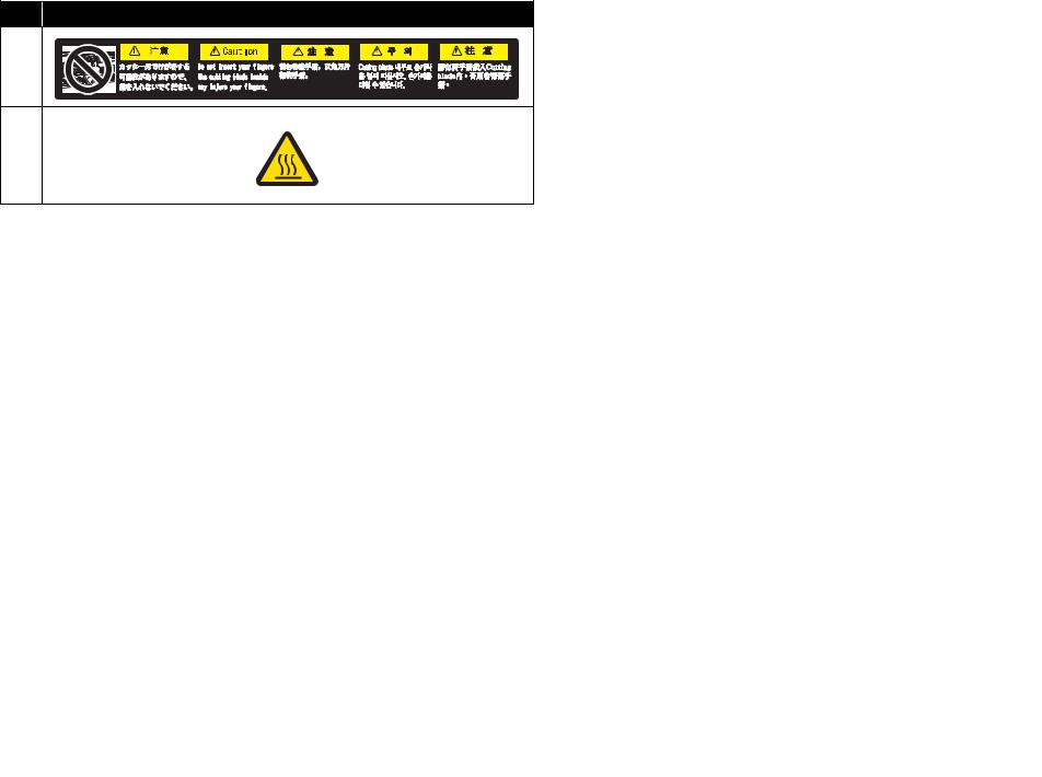
1.2.2Location and Type of Warning Labels
The locations of warning labels are shown in the following figure.
1
2
2
2
1.2Warning Labels
This section explains the handling of warning label, pasting location and types. Warning labels are attached to parts of the printer that need special caution. Understand the locations and the descriptions of the danger associated with each label before operating the printer.
1.2.1Handling the Warning Labels
Make sure to note the following when handling the warning labels.
1.1.1 Types and Meanings of Warnings |
P.1-2 |
1.2 Warning Labels |
VJ1324E-M-02 |
No. |
Types of Warning Labels |
1 |
|
2 |
|
1.2.2 Location and Type of Warning Labels |
P.1-3 |

VJ1324E-M-02
2 Trouble Shooting
2.1 Introduction .................................................................. |
2- 2 |
|
2.2 Troubleshooting with Error Messages....................... |
2- 7 |
|
2.2.1 |
Operation Status ................................................. |
2-7 |
2.2.2 |
Errors with Message ........................................... |
2-9 |
2.2.3 |
Errors Requiring Reboot ................................... |
2-15 |
2.2.4 Error Messages During File Transmission ........ |
2-32 |
|
2.3 Troubleshooting Without Error Messages............... |
2- 35 |
|
2.3.1 |
Initial Operation Problems................................. |
2-35 |
2.3.2 |
Media Feed Problems ....................................... |
2-41 |
2.3.3 |
Printing Problems.............................................. |
2-44 |
2.3.4 |
Noise Problems................................................. |
2-57 |
2.3.5 |
Media Cutting Problems ........................................ |
2-60 |
2.3.6 |
Online Function Problems................................. |
2-63 |
2.3.7 |
Other Problems ................................................. |
2-65 |
2.3.8 |
Problems in Using MUTOH Service Assistance 2-67 |
|
P.2-1
2.1 Introduction |
VJ1324E-M-02 |
2.1Introduction
This chapter provides information on possible causes of machine errors/damage and recovery actions.
If the machine is malfunctioning and an error message is displayed on Operation panel, refer to"2.2 Troubleshooting with Error Messages" p.2-7. If the machine is malfunctioning but no error messages are displayed, refer to"2.3 Troubleshooting Without Error Messages" p.2-35If cause of errors/damage and recovery actions are not found in this chapter, or the machine cannot restore to normal status, please contact the distributor you purchased the product from or our customer support center.
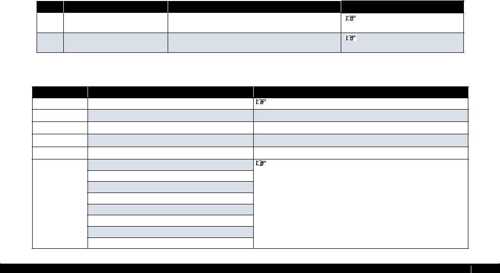
Table 2-1 Error type
No. |
Trouble |
Contents |
Reference |
1 |
When the message is displayed |
Trouble with an error message displayed on Operation panel when the |
"2.2 Troubleshooting with Error |
|
|
printer is malfunctioning. |
Messages" p.2-7 |
2 |
When the message is not displayed |
Trouble without an error message displayed on Operation panel even |
"2.3 Troubleshooting Without Error |
|
|
when the printer is malfunctioning. |
Messages" p.2-35 |
|
|
Table 2-2 When the message is displayed |
Message type |
Contents |
Reference |
Operation status |
Cover open |
"2.2.1 Operation Status" p.2-7 |
Mainte. Cover[*] Open (*L or R)
Set media
End of Roll
No media
Error with message Undefined Media |
"2.2.2 Errors with Message" p.2-9 |
Media Slant
Ink NearEnd
Ink End
NoCartridges
S/C Read Err
S/C Ink Err
S/C Code Err
P.2-2

2.1 Introduction |
|
VJ1324E-M-02 |
|
Table 2-2 When the message is displayed (Continued) |
|
Message type |
Contents |
Reference |
Error with message |
S/C Col. Err |
"2.2.2 Errors with Message" p.2-9 |
|
Full wasteInk Tank |
|
|
Media cut Err |
|
|
Smart/C End |
|
|
Broken Chip |
|
|
Check Life [Head ] |
|
|
Check Life [Pump] |
"2.2.2 Errors with Message" p.2-9 |
|
Check Life [CR Motor] |
|
|
Check Life [PF Motor] |
|
Error requiring restart |
E016 Error (CPU errors) [00] - [35] |
"2.2.3 Errors Requiring Reboot" p.2-15 |
|
E016 Errors (Mechanical errors) [065] - [152] |
|
Errors while |
Transfer failed ******. |
"2.2.4 Error Messages During File Transmission" p.2-32 |
transmitting/ |
Boot transfer failed ******. |
|
receiving data |
|
|
|
|
|
P.2-3
2.1 Introduction |
|
VJ1324E-M-02 |
||
|
|
Table 2-3 When the message is not displayed |
||
|
|
|
|
|
|
Message |
Symptoms |
Reference |
|
|
|
|||
|
|
|
|
|
|
Initial Operation |
Printer cannot be turned on |
"2.3.1 Initial Operation Problems" p.2-35 |
|
|
Problems |
|
|
|
|
|
|
|
|
|
|
LCD display malfunction |
|
|
|
|
|
|
|
|
|
Initial ink charge does not start |
|
|
|
|
|
|
|
|
|
Initial ink charge started, but ink does not reach Head |
|
|
|
|
|
|
|
|
|
Ink does not come out even after initial ink charge is completed |
|
|
|
|
|
|
|
|
|
The printer does not operate after turned on. |
|
|
|
|
|
|
|
|
|
The printer does not stop operation even when Front cover or |
|
|
|
|
Maintenance cover is opened. |
|
|
|
|
|
|
|
|
|
After the printer is turned on, "Initializing" is displayed and the |
|
|
|
|
printer resets |
|
|
|
|
Loading media does not start the initial operation |
|
|
|
|
|
|
|
|
|
The printer does not operate even when Front cover or Maintenance |
|
|
|
|
cover is closed. |
|
|
|
|
The printer does not recognize the installed ink cartridges |
|
|
|
|
|
|
|
|
|
Nothing can be input from Operation panel |
"2.3.1 Initial Operation Problems" p.2-35 |
|
|
|
|
|
|
|
|
Printing does not start even after receiving data. |
|
|
|
|
|
|
|
|
Media Feed Problems |
Media slips during media initialization or printing. |
"2.3.3 Printing Problems" p.2-44 |
|
Media skews or meanders during media initialization or printing.
Media wrinkles during media initialization or printing.
Media tears during media initialization or printing.
Media size is not correctly detected after media initialization.
LCD display malfunction
P.2-4
2.1 Introduction |
|
VJ1324E-M-02 |
|||
|
|
Table 2-3 When the message is not displayed (Continued) |
|||
|
|
|
|
|
|
|
Message |
Symptoms |
Reference |
|
|
|
|
|
|
|
|
|
Printing Problems |
The printer does not print continuously. |
"2.3.3 Printing Problems" p.2-44 |
||
|
|
|
|
|
|
|
|
After printing, the printer feeds an extra amount of media. |
|
|
|
|
|
|
|
|
|
|
|
Nozzles are clogged during printing |
|
|
|
|
|
|
|
|
|
|
|
Cleaning does not mend the clogged nozzles or skewed ink |
|
|
|
|
|
discharge. |
|
|
|
|
|
|
|
|
|
|
|
Cannot print at all, a specific color is missing |
|
|
|
|
|
|
|
|
|
|
|
The page is printed all black. |
|
|
|
|
|
|
|
|
|
|
|
The page is printed blocky. |
|
|
|
|
|
|
|
|
|
|
|
Images are printed unevenly. |
|
|
|
|
|
|
|
|
|
|
|
Lines in the CR direction look split. |
|
|
|
|
|
|
|
|
|
|
|
White or black lines appear on printed media |
|
|
|
|
|
|
|
|
|
|
|
The printed borders are blurred. |
|
|
|
|
|
|
|
|
|
|
|
There are unwanted dots (satellites). |
|
|
|
|
|
|
|
|
|
|
|
Characters with jagged edges are printed. |
|
|
|
|
|
|
|
|
|
|
|
Lines are printed blurry (messy printing result) |
"2.3.3 Printing Problems" p.2-44 |
||
Mixed color lines are not overlapped.
The printed results are uneven. (Vertical direction against the printer unit)
The printed results are uneven. (Horizontal direction against the printer unit)
Noise Problems Abnormal noise is heard when media is sucked 

 "2.3.4 Noise Problems" p.2-57
Abnormal noise is heard during waiting time
Abnormal noise is heard while Head is moving laterally
Abnormal noise is heard when feeding media
P.2-5
2.1 Introduction |
|
VJ1324E-M-02 |
||
|
|
Table 2-3 When the message is not displayed (Continued) |
||
|
|
|
|
|
|
Message |
Symptoms |
Reference |
|
|
|
|
|
|
|
Online Function |
Other functions do not work correctly |
"2.3.6 Online Function Problems" p.2-63 |
|
|
Problems |
|
|
|
|
|
|
|
|
|
|
Data or printing is garbled |
|
|
|
|
|
|
|
|
|
Part of the data is not printed (missing) |
|
|
|
|
|
|
|
|
Other Problems |
The printer hangs up |
"2.3.7 Other Problems" p.2-65 |
|
|
|
|
|
|
|
|
The power is shut down during printing |
|
|
|
|
|
|
|
|
|
Ink cartridges cannot be inserted |
|
|
|
|
|
|
|
|
|
Ink spills out of Waste fluid tank |
|
|
|
|
|
|
|
|
|
Ink spills out of Flushing box |
|
|
|
|
|
|
|
|
|
Ink spills around X rail |
|
|
|
|
|
|
|
|
Problems in Using |
MUTOH Service Assistance does not start up |
"2.3.8 Problems in Using MUTOH Service Assistance" p.2-67 |
|
|
MUTOH Service |
|
|
|
|
Assistance |
|
|
|
|
|
|
|
|
|
|
"Transfer failed (Data timeout)" is displayed during transfer. |
|
|
|
|
|
|
|
|
|
"Main F/W data is invalid" is displayed during firmware transfer. |
|
|
|
|
|
|
|
|
|
"No compatibility between main F/W data and printer" is displayed |
|
|
|
|
during firmware transfer. |
|
|
|
|
|
|
|
|
|
"F/W version downgrade is not available" is displayed during |
"2.3.8 Problems in Using MUTOH Service Assistance" p.2-67 |
|
|
|
firmware transfer. |
|
|
|
|
|
|
|
|
|
"Heater controller F/W data is invalid" is displayed during Heater |
|
|
|
|
controller firmware transfer. |
|
|
|
|
|
|
|
|
|
"No compatibility between Heater controller F/W data and printer is |
|
|
|
|
displayed during Heater controller firmware transfer. |
|
|
|
|
|
|
|
P.2-6
2.2 Troubleshooting with Error Messages |
VJ1324E-M-02 |
2.2Troubleshooting with Error Messages
This section describes the messages displayed in normal operation and upon an error occurrence as well as how to correct the error. The available messages are as follows.
2.2.1Operation Status
This section describes the message contents, check items, and recovery actions for normal operation.
|
|
|
|
Table 2-4 Events and Check Items for Operation Status Messages |
|
|
|
|
|
|
|
|
|
|
|
||
|
|
|
|
|
|
|
|
|
No. |
Message |
Event/symptom |
|
Check item |
Action |
|
|
Reference |
|
|
|
|
|
|
|
|
|
1 |
Cover open |
Front cover is |
1. |
Is Cover sensor Assy wobbly? |
Tighten the screw on Cover sensor Assy . |
|
|
"3.3.3 Replacing Cover Switch |
|
|
open. |
|
|
|
|
|
Assy Sensor Cover L Assy, Sensor |
|
|
2. |
Are the cables of F cover R sensor Assy and F cover L sensor |
Securely connect the cable of F cover R sensor |
|
|
||
|
|
|
|
|
||||
|
|
|
|
Assy securely connected? |
|
|
and |
Cover R Assy" p.3-25 |
|
|
|
|
|
Assy to MAIN board Assy connector J13) |
|
|
|
|
|
|
|
|
the cable of F cover L sensor Assy to MAIN board |
"3.3.4 Replacing Cover L Cable |
||
|
|
|
|
|
Assy connector J14). |
|
|
Assy" p.3-32 |
|
|
|
|
|
|
|
|
"3.3.5 Replacing Cover R Cable |
|
|
|
3. |
Are F cover R sensor Assy and F cover L sensor Assy |
Replace F cover R sensor Assy and F cover L sensor |
Assy" p.3-35 |
||
|
|
|
|
damaged? |
Assy . |
|
|
|
4.Check the operation of Cover sensor in “Sen 4: Lever” in the self-diagnosis function.
|
|
|
5. |
MAIN board Assy may be damaged. |
Replace MAIN board Assy . |
"3.4.4 Replacing MAIN Board |
|
|
|
|
|
|
Assy" p.3-42 |
2 |
Set media |
Media holding |
1. |
Does Pressurizing lever move smoothly? |
Lubricate pressure cam. |
"7.5 Lubrication/Bonding" p.7- |
|
|
lever is raised. |
|
|
|
7 |
|
|
|
|
|
|
|
|
|
|
2. |
Is Lever sensor Assy securely installed? |
Adjust the mounting position of Lever sensor Assy . |
"3.6.7 Replacing T Fence, T |
|
|
|
|
|
|
Fence Spring Assy" p.3-93 |
|
|
|
3. |
Is the sensor portion of Lever sensor Assy dirty? |
Clean the sensor portion with a cotton swab, etc. |
"3.6.5 Replacing Lever Sensor" |
|
|
|
|
|
|
p.3-91 |
|
|
|
4. |
Is Lever sensor Assy securely installed? |
Securely connect Lever sensor cable Assy to |
"3.6.6 Replacing Lever Sensor |
|
|
|
|
|
JUNCTION board Assy connector J15. |
Cable Assy" p.3-92 |
|
|
|
5. |
Check the operation of Lever sensor in “Sen 6: Lever” in the |
Replace Lever sensor Assy if it is not working |
"3.6.5 Replacing Lever Sensor" |
|
|
|
|
self-diagnosis function. |
properly. |
p.3-91 |
|
|
|
|
|
|
|
|
|
|
6. |
MAIN board Assy may be damaged. |
Replace MAIN board Assy . |
"3.4.4 Replacing MAIN Board |
|
|
|
|
|
|
Assy" p.3-42 |
2.2.1 Operation Status |
P.2-7 |
2.2 Troubleshooting with Error Messages |
VJ1324E-M-02 |
Table 2-4 Events and Check Items for Operation Status Messages(Continued)
No. |
Message |
Event/symptom |
|
Check item |
Action |
|
Reference |
|
3 |
No media |
Displayed in the |
1. |
Is media edge sensor Assy cable at the head section |
Securely connect it to CR board Assy connector. |
"3.7.4 Replacing CR Board |
||
|
|
following cases: |
|
connected correctly? |
|
|
Assy" p.3-101 |
|
|
|
• |
When media |
|
|
|
|
|
|
|
2. |
Is media rear sensor Assy under media guide R connected |
Securely connect it to MAIN board |
Assy connector. |
|
||
|
|
|
is not set |
"3.4.4 Replacing MAIN Board |
||||
|
|
• |
When |
|
correctly? |
|
|
Assy" p.3-42 |
|
|
|
printing |
3. |
Check sensor sensitivity from "Sen7: Edge AD" of self- |
Replace P_Edge sensor Assy . |
|
"3.7.16 Replacing P_EDGE |
|
|
|
finishes in |
|
||||
|
|
|
cut media |
|
diagnosis function. |
|
|
Sensor Assy" p.3-135 |
|
|
|
mode |
4. |
CR board Assy may be damaged. |
Replace CR board Assy . |
|
"3.7.4 Replacing CR Board |
|
|
|
|
|
||||
|
|
|
|
|
|
|
|
Assy" p.3-101 |
|
|
|
|
5. |
Check presence of media from "Sen8: Rear AD" of self- |
When "No media" is displayed even if media is set, |
"3.10.2 Replacing P_REAR |
|
|
|
|
|
|
diagnosis function. |
replace P_Rear sensor Assy . |
|
Sensor" p.3-150 |
|
|
|
|
|
|
|
|
|
|
|
|
|
6. |
CR_FFC may be damaged. |
Replace CR_FFC. |
|
"3.11.3 Replacing CR_FFC" |
|
|
|
|
|
|
|
|
p.3-154 |
|
|
|
|
7. |
MAIN board Assy may be damaged. |
Replace MAIN board Assy . |
|
"3.4.4 Replacing MAIN Board |
|
|
|
|
|
|
|
|
Assy" p.3-42 |
4 |
Maintenance |
Maintenance |
1. |
Is the maintenance cover open? |
Close maintenance cover. |
|
Operation Manual |
|
|
cover open |
cover is open. |
2. |
Is maintenance cover sensor Assy loose? |
Tighten the screws of maintenance cover sensor Assy |
"3.3.3 Replacing Cover Switch |
||
|
|
|
|
|||||
|
|
|
|
|
|
. |
|
Assy Sensor Cover L Assy, Sensor |
|
|
|
|
|
|
|
|
|
|
|
|
|
3. |
Is the cable of maintenance cover sensor Assy securely |
Securely connect the cable of maintenance cover |
Cover R Assy" p.3-25 |
|
|
|
|
|
|
connected? |
sensor Assy to MAIN board Assy. |
|
|
|
|
|
|
4. |
Is maintenance cover sensor Assy damaged? |
Replace maintenance cover sensor |
Assy . |
|
2.2.1 Operation Status |
P.2-8 |
2.2 Troubleshooting with Error Messages |
VJ1324E-M-02 |
2.2.2Errors with Message
This section describes the contents of errors with messages as well as the check items and recovery actions.
These messages are displayed when an abnormal condition occurs while the machine is running.
Upon an occurrence of an error with message, the machine stops its operation at the same time.
The error can be cancelled by removing the error causes. After that, the machine will restart its operation.
No. |
Message |
Event/ |
Check item |
Action |
Reference |
|
|
symptom |
|
|
|
1 |
Media detection |
Media detection 1. |
Is media edge sensor Assy cable at head connected correctly? |
Securely connect it to CR board Assy connector. |
"3.7.4 Replacing CR Board |
|
error |
failed |
|
|
Assy" p.3-101 |
|
|
|
|
|
|
|
|
2. |
Is media rear sensor Assy under media guide R connected |
Securely connect it to MAIN board Assy connector. |
"3.4.4 Replacing MAIN Board |
|
|
|
correctly? |
|
Assy" p.3-42 |
|
|
|
|
|
|
|
|
3. |
Check sensor sensitivity from "Sen8:Edge AD" of self- |
Replace P_Edge sensor Assy . |
"3.7.16 Replacing P_EDGE |
|
|
|
diagnosis function. |
|
Sensor Assy" p.3-135 |
|
|
|
|
|
|
|
|
4. |
Is CR_FFC cable inserted obliquely? |
Securely connect to MAIN board Assy and CR board |
"3.4.4 Replacing MAIN Board |
|
|
|
|
Assy |
Assy" p.3-42 |
|
|
|
|
|
|
|
|
|
|
|
"3.7.4 Replacing CR Board |
|
|
|
|
|
Assy" p.3-101 |
|
|
5. |
CR_FFC may be damaged. |
Replace CR_FFC. |
"3.11.3 Replacing CR_FFC" |
|
|
|
|
|
p.3-154 |
|
|
6. |
CR board Assy may be damaged. |
Replace CR board Assy . |
"3.7.4 Replacing CR Board |
|
|
|
|
|
Assy" p.3-101 |
|
|
7. |
Check presence of media from "Sen7:Rear AD" of self- |
When "No media" is displayed even if media is set, |
"3.10.2 Replacing P_REAR |
|
|
|
diagnosis function. |
replace P_Rear sensor. |
Sensor" p.3-150 |
|
|
|
|
|
|
|
|
8. |
MAIN board Assy may be damaged. |
Replace MAIN board Assy . |
"3.4.4 Replacing MAIN Board |
|
|
|
|
|
Assy" p.3-42 |
2.2.2 Errors with Message |
P.2-9 |

2.2 Troubleshooting with Error Messages VJ1324E-M-02
No. |
Message |
Event/ |
|
Check item |
|
Action |
|
|
Reference |
|
|
symptom |
|
|
|
|
|
|
|
|
|
|
|
|
|
|
|
|
|
2 |
Media skew |
Media is running |
1. |
Set media again and check reappearance. |
If this error is caused by user's inappropriate media |
― |
|||
|
error |
obliquely. |
|
|
setting, instruct correct media setting procedure. |
|
|
|
|
|
|
|
|
|
|
|
|
|
|
|
|
|
2. |
Is suction fan judged as normal when checked through "Test: |
Check the connection of following MAIN |
|
|
"3.10.1 Replacing Adsorption |
|
|
|
|
|
Fan" of self-diagnosis function? |
board Assy connectors. |
FAN" p.3-149 |
|||
|
|
|
|
|
• |
Suction fan relay Assy J27 |
|
|
|
|
|
|
|
|
• Replace cable of suction fan that does not |
|
|
|
|
|
|
|
|
|
|
operate normally. |
|
|
|
|
|
|
|
|
• |
Replace suction fan Assy . |
|
|
|
|
|
|
|
|
|
|
|
|
|
|
|
|
3. |
Is shielding material secured at specified position? |
Remount it at specified position. |
|
|||
|
|
|
|
|
|
|
|
|
|
|
|
|
4. |
Check pressure lever operation. |
Apply grease (G501) to pressure cam and make |
|
|
"7.5 Lubrication/Bonding" p.7- |
|
|
|
|
|
|
|||||
|
|
|
|
|
|||||
|
|
|
|
|
adjustment. |
7 |
|||
|
|
|
|
|
|
|
|||
|
|
|
|
|
|
|
|
|
|
3 |
Remove media |
Displayed if lever |
1. |
Does the same message appear if turning machine OFF and |
If the message appears, refer to the action in check |
― |
|||
|
|
is raised during |
|
turn it ON again? |
item No. 2. |
|
|
|
|
|
|
printing or cutting |
|
|
|
|
|
|
|
|
|
2. |
Is pressure lever detected as normal when checked through |
Check that LCD monitor does not display up/down as |
|
|
"5.5.4 Sensor Menu" p.5-12 |
||
|
|
media and then |
|
"Sen: Lever" of self-diagnosis function? |
chattering when slowly raising/lowering pressure |
|
|
|
|
|
|
lowered without |
|
|
|
|
|||
|
|
|
|
lever. |
|
|
|
||
|
|
removing media. |
|
|
|
|
|
||
|
|
|
|
|
|
|
|
|
|
|
|
|
3. |
Check contact of lever sensor Assy . |
• |
Reconnect MAIN board Assy connector |
|
|
"3.4.11 Replacing JUNCTION |
|
|
|
|
|
|
J15. |
Board Assy" p.3-51 |
||
|
|
|
|
|
• If LCD displays as chattering, sensor may |
|
|
"3.6.5 Replacing Lever Sensor" |
|
|
|
|
|
|
|
be damaged. Replace lever sensor Assy . |
p.3-91 |
||
|
|
|
|
|
|
|
|
|
|
|
|
|
4. |
Is media rear sensor Assy under media guide R connected |
Securely connect it to MAIN board Assy connector |
|
|
"3.4.4 Replacing MAIN Board |
|
|
|
|
|
correctly? |
J26. |
|
Assy" p.3-42 |
||
|
|
|
|
|
|
|
|||
|
|
|
|
|
|
|
|
|
|
|
|
|
5. |
Check presence of media from "Sen: Rear AD" of self- |
When "No media" is displayed even if media is set, |
|
|
"3.10.2 Replacing P_REAR |
|
|
|
|
|
diagnosis function. |
replace P_Rear sensor Assy . |
Sensor" p.3-150 |
|||
|
|
|
|
|
|
|
|||
|
|
|
|
|
|
|
|
|
|
|
|
|
6. |
MAIN board Assy may be damaged. |
Replace MAIN board Assy . |
|
|
"3.4.4 Replacing MAIN Board |
|
|
|
|
|
|
|
|
Assy" p.3-42 |
||
|
|
|
|
|
|
|
|
|
|
2.2.2 Errors with Message |
P.2-10 |
2.2 Troubleshooting with Error Messages VJ1324E-M-02
No. |
Message |
Event/ |
|
Check item |
|
Action |
|
|
Reference |
|
|
symptom |
|
|
|
|
|
|
|
|
|
|
|
|
|
|
|
|
|
4 |
Media cut error |
Even though |
1. |
Does media dust accumulate in cutter groove? |
Remove accumulated media dust along groove. |
|
|
Operation Manual |
|
|
|
cutting operation |
|
|
|
|
|
|
|
|
|
is performed, |
|
|
|
|
|
|
|
|
|
media is not cut |
|
|
|
|
|
|
|
|
|
off. |
|
|
|
|
|
|
|
|
|
|
|
|
|
|
|
||
|
|
|
2. Is cutter cap securely installed? |
Reinstall cutter cap securely. |
|
|
Operation Manual |
||
|
|
|
|
|
|
|
|
|
|
|
|
|
3. |
Check cutter sliding up/down operation. |
• When it does not rise: |
― |
|||
|
|
|
4. |
When setting cutter, lower cutter with finger and check that |
|
Refer to action in check item No. 4. |
|
|
|
|
|
|
• |
When it rises: |
|
|
|
||
|
|
|
|
cutter rises to upper end only by spring force. |
|
|
|
||
|
|
|
|
|
Refer to action in check item No. 5. |
|
|
|
|
|
|
|
|
|
|
|
|
|
|
|
|
|
|
|
|
|
|
|
|
|
|
|
5. When setting cutter after removing cutter spring, does cutter |
• |
When it lowers: |
|
|
"3.7.15 Replacing Cutter |
|
|
|
|
|
lower to lower end by its own weight? |
|
Cutter spring may be defective. Replace cutter |
Solenoid Assy, Cutter Solenoid |
||
|
|
|
|
|
|
spring referring to exploded views. |
|||
|
|
|
|
|
|
Spring Assy" p.3-133 |
|||
|
|
|
|
|
• When it does not lower: |
||||
|
|
|
|
|
|
|
|
||
|
|
|
|
|
|
Cutter may be defective. Replace cutter. |
|
|
|
|
|
|
|
|
|
|
|
|
|
|
|
|
6. Check if solenoid goes up/down from "Life: Cutter" |
- |
|
- |
|||
|
|
|
|
of self-diagnosis function. |
• |
OK: |
|
|
|
|
|
|
|
|
|
Operation Manual |
|||
|
|
|
|
a) Goes up/down: |
|
Cutter has reached the end of life or be damaged. |
|
|
|
|
|
|
|
|
|
|
|||
|
|
|
|
|
|
|
|
||
|
|
|
|
|
Replace cutter with new one. |
|
|
|
|
|
|
|
|
Check the position where cutter goes down to cutter |
|
|
|
"3.7.15 Replacing Cutter |
|
|
|
|
|
• |
NG: |
|
|
||
|
|
|
|
groove. |
|
Adjust cutter holder position. |
Solenoid Assy, Cutter Solenoid |
||
|
|
|
|
b) Does not go up/down: |
Connector may be poorly connected. |
Spring Assy" p.3-133 |
|||
|
|
|
|
|
|
|
|||
|
|
|
|
|
Check the connection of following connectors. |
|
|
"3.7.4 Replacing CR Board |
|
|
|
|
|
|
|
|
Assy" p.3-101 |
||
|
|
|
|
|
|
|
|
|
"3.4.4 Replacing MAIN Board |
|
|
|
|
|
|
|
Assy" p.3-42 |
||
|
|
|
|
|
|
|
|
|
|
|
|
|
7. |
CR_FFC may be broken, solenoid Assy may be |
If solenoid goes up/down, replace CR_FFC. |
|
|
"3.11.3 Replacing CR_FFC" |
|
|
|
|
|
defective, or each board Assy may be defective. |
|
|
p.3-154 |
||
a) Replace CR_FFC with new one.
2.2.2 Errors with Message |
P.2-11 |
2.2 Troubleshooting with Error Messages |
VJ1324E-M-02 |
No. |
Message |
Event/ |
|
|
symptom |
|
|
|
4 |
Media cut error |
Even though |
|
|
cutting |
|
|
operation is |
|
|
performed, |
|
|
media is not cut |
|
|
off. |
|
|
|
Check item |
Action |
Reference |
b)Replace solenoid Assy with new one. (Check by connecting connectors directly)
c)Replace CR board Assy .
d)Replace MAIN board Assy .
If solenoid goes up/down, replace solenoid Assy .
After replacement, adjust sensor reflection amount from "Sen: Edge AD" of "Test: Sensor" of selfdiagnosis function.
Before replacing MAIN board, back up parameters and recover to new MAIN board Assy . Then start operation check.


 "3.7.15 Replacing Cutter
Solenoid Assy, Cutter Solenoid
Spring Assy" p.3-133


 "3.7.4 Replacing CR Board
Assy" p.3-101


 "3.4.4 Replacing MAIN Board
Assy" p.3-42
2.2.2 Errors with Message |
P.2-12 |

2.2 Troubleshooting with Error Messages VJ1324E-M-02
No. |
|
Message |
|
Event/ |
|
Check item |
|
Action |
Reference |
|
|
|
|
symptom |
|
|
|
|
|
|
|
|
|
|
|
|
|
|
|
4 |
1. |
[KCMY] |
1. |
Ink is |
1. |
Check which cartridge has no ink from "Sen: Ink NOT" of |
Remove all cartridges and lightly push the black resin |
"5.5.4 Sensor Menu" p.5-12 |
|
|
|
Ink Near End |
|
running |
|
self-diagnosis function. |
lever of ink sensor Assy (K, C, M, Y) to check that |
|
|
|
2. |
[KCMY] |
|
short. |
|
|
the display of "Sen: Ink NOT" changes. |
|
|
|
|
Printing is |
|
|
|
|
|
||
|
|
Ink End |
|
|
|
|
|
|
|
|
|
|
possible. |
|
|
|
|
|
|
|
The ink color that |
|
2. |
Check contact of the ink sensor Assy . |
Reconnect following connectors. |
"3.4.4 Replacing MAIN Board |
|||
|
|
|
|||||||
|
is/are subject to |
2. |
Ink has run |
|
|
• |
connector18(K) |
Assy" p.3-42 |
|
|
this caution is/are |
|
out. Any |
|
|
• |
connectorJ9(C) |
|
|
|
displayed in the [ |
|
printing |
|
|
• |
connectorJ10(M) |
|
|
|
|
operation |
|
|
|
||||
|
]. |
|
|
|
|
• |
connectorJ11(Y) |
|
|
|
|
|
stops |
|
|
|
|||
|
|
|
|
|
|
|
|||
|
|
|
|
immediately. |
3. |
For the ink color that is displayed as "Ink Near End" or "Ink |
• |
If ink color display changes after |
"3.9.1 Replacing Cartridge |
|
|
|
|
|
|
End", switch ink sensor Assy connector with that of normally |
|
replacing connector: |
Holder Assy" p.3-146 |
|
|
|
|
|
|
displayed ink color. |
|
Ink sensor Assy is damaged. Replace ink |
|
|
|
|
|
|
|
|
|
sensor Assy . |
|
|
|
|
|
|
|
|
• |
If ink color display does not change after |
|
|
|
|
|
|
|
|
|
replacing connector: |
"3.4.4 Replacing MAIN Board |
|
|
|
|
|
|
|
|
MAIN board Assy may be |
Assy" p.3-42 |
|
|
|
|
|
|
|
|
damaged.Replace MAIN board Assy . |
|
|
|
|
|
|
|
|
|||
5 |
[KCMY] |
Cartridge is not |
1. |
Turn machine OFF. Turn it ON again and check if the same |
If message appears: Refer to action in check item No. |
― |
|||
|
No Cartridge |
installed. |
|
message appears. |
2. |
|
|
||
|
|
|
|
|
|
|
|
||
|
|
|
|
|
2. Check presence of ink cartridge from "Sen: Ink NOT" of self- |
Remove all cartridges and lightly push the switch of |
"5.5.4 Sensor Menu" p.5-12 |
||
|
|
|
|
|
|
diagnosis function. |
ink NOT sensor Assy (K, C, M, Y) with something |
|
|
|
|
|
|
|
|
|
with a flat tip such as ballpoint pen to check that the |
|
|
|
|
|
|
|
|
|
display of "Sen: Ink NOT" changes. |
|
|
|
|
|
|
|
|
|
|
|
|
|
|
|
|
|
3. |
Check contact of ink sensor Assy connector. |
Reconnect following connectors. |
"3.4.4 Replacing MAIN Board |
|
|
|
|
|
|
|
|
• |
connector 15(K) |
Assy" p.3-42 |
|
|
|
|
|
|
|
• |
connector J6(C) |
|
|
|
|
|
|
|
|
• |
connector J7(M) |
|
|
|
|
|
|
|
|
• |
connector J8(Y) |
|
|
|
|
|
|
|
|
|
||
|
|
|
|
|
4. For the ink color that is displayed as "No cartridge", switch |
If ink color displayed as "No cartridge" changes after |
"3.9.1 Replacing Cartridge |
||
|
|
|
|
|
|
ink sensor Assy connector with that of normally displayed |
replacing connector: |
Holder Assy" p.3-146 |
|
|
|
|
|
|
|
ink color. |
Ink sensor Assy is damaged. Replace ink |
||
|
|
|
|
|
|
|
|||
|
|
|
|
|
|
|
sensor Assy . |
|
|
|
|
|
|
|
|
|
|
|
|
2.2.2 Errors with Message |
P.2-13 |

2.2 Troubleshooting with Error Messages VJ1324E-M-02
No. |
Message |
Event/ |
Check item |
Action |
Reference |
|
|
symptom |
|
|
|
|
|
|
|
|
|
6 |
Life Times |
The operational |
Check the condition of Head. |
Replace Head as necessary. Clear the counter after |
"3.7.6 Replacing Print Head" |
|
[Head] |
life of Print head |
|
replacing it. |
p.3-106 |
|
|
has almost |
|
|
|
|
|
expired. |
|
|
|
|
|
|
|
|
|
7 |
Life Times [PF |
The operational |
The operational life of PF motor has almost expired. |
Replace PF motor as necessary. Clear the counter after |
"3.5.1 Replace PF Motor Assy" |
|
Motor] |
life of PF motor |
|
replacing it. |
p.3-61 |
|
|
has almost |
|
|
|
|
|
|
|
|
|
|
|
expired. |
|
|
|
|
|
|
|
|
|
8 |
Life Times [CR |
The operational |
Check the condition of CR motor. |
Replace CR motor as necessary. Clear the counter |
"3.6.1 Replacing CR Motor |
|
Motor] |
life of CR motor |
|
after replacing it. |
Assy" p.3-86 |
|
|
has almost |
|
|
|
|
|
expired. |
|
|
|
|
|
|
|
|
|
9 |
Life Times |
The operational |
Check the condition of Pump. |
Replace Pump as necessary. Clear the counter after |
"3.8.1 Replacing Maintenance |
|
[Pump] |
life of Pump has |
|
replacing it. |
Assy" p.3-138 |
|
|
almost expired. |
|
|
|
|
|
|
|
|
|
|
|
|
|
|
|
NOTE
•The square bracket pair in an error message indicates the applicable ink color.
•If no ink and no cartridge occur at the same time, no cartridge message has priority to be displayed.
|
|
|
|
|
|
|
|
|
2.2.2 Errors with Message |
P.2-14 |
|
|
|
|
|

2.2 Troubleshooting with Error Messages |
VJ1324E-M-02 |
2.2.3Errors Requiring Reboot
This section describes the contents of reboot-requiring errors as well as the check items and recovery actions.
These errors are issued when any of the following critical problems occur.
•Obstacle that prevents the machine's operation
•Damage of electric circuits (Boards, Motors, Sensors)
•Abnormal operation of control programs
When any of the above conditions occur, the machine follows the steps shown below before stopping its operation.
1.Turn OFF the driving system power automatically.
2.Flash all lamps on Operation panel and generate intermittent audible alarm.
3.Display the applicable error message on the LCD.
The error can be cancelled by removing the error causes and restarting the machine.
(1) CPU system serious error
No. |
Message |
Event/ |
Check item |
Action |
Reference |
|
|
symptom |
|
|
|
|
|
|
|
|
|
1 |
E 016Interrupt |
Interruption |
|
00 |
exception error: |
|
|
An anomaly is |
|
|
detected during |
|
|
interruption |
|
|
process. |
|
|
|
2 |
E016 TLB Modif |
Command border |
|
[01] |
exception/TLB |
|
|
exception (load or |
|
|
command fetch) |
|
|
error: |
|
|
An anomaly is |
|
|
detected in |
|
|
command border. |
|
|
Or TLB exception |
|
|
is detected while |
|
|
loading data or |
|
|
fetching data. |
1. Check AC power supply and printer peripherals. |
• Replace MAIN board Assy . |
2.Check whether the same error occurs. Even when there is no problem, turn off the printer and turn it back on a few times to check.
3.Check the serial number of the printer.
4.MAIN board Assy may be damaged.


 Operation Manual


 "3.4.4 Replacing MAIN Board
Assy" p.3-42
2.2.3 Errors Requiring Reboot |
P.2-15 |

2.2 Troubleshooting with Error Messages |
|
|
VJ1324E-M-02 |
||
|
|
|
|
|
|
No. |
Message |
Event/ |
Check item |
Action |
Reference |
|
|
symptom |
|
|
|
|
|
|
|
|
|
3 |
E 016 TLB-L/1 |
Data border |
1. |
Check AC power supply and printer peripherals. |
• Replace MAIN board Assy . |
|
02 |
exception/TLB |
2. |
Check whether the same error occurs. Even when there is no |
|
|
|
exception (store) |
|
||
|
|
|
problem, turn off the printer and turn it back on a few times to |
|
|
|
|
error: |
|
|
|
|
|
|
check. |
|
|
|
|
An anomaly is |
|
|
|
|
|
3. |
Check the serial number of the printer. |
|
|
|
|
detected in data |
|
||
|
|
border. |
4. |
MAIN board Assy may be damaged. |
|
|
|
Or TLB exception |
|
||
|
|
is detected while |
|
|
|
|
|
storing data. |
|
|
|
|
|
|
|
|
|
4 |
E 016 TLB-S |
Data border |
|
|
|
|
03 |
exception/TLB |
|
|
|
|
|
exception (store) |
|
|
|
|
|
error: |
|
|
|
|
|
An anomaly is |
|
|
|
|
|
detected in data |
|
|
|
|
|
border. |
|
|
|
|
|
Or TLB exception |
|
|
|
|
|
is detected while |
|
|
|
|
|
storing data. |
|
|
|
|
|
|
|
|
|
5 |
E 016 AddErr-L/l |
Address |
|
|
|
|
04 |
exception error |
|
|
|
|
|
(load or command |
|
|
|
|
|
fetch): |
|
|
|
|
|
Address error is |
|
|
|
|
|
detected while |
|
|
|
|
|
loading or |
|
|
|
|
|
fetching |
|
|
|
|
|
command. |
|
|
|
|
|
|
|
|
|
6 |
E 016 AddErr-S |
Address |
|
|
|
|
05 |
exception error |
|
|
|
|
|
(store): |
|
|
|
|
|
An address error |
|
|
|
|
|
is detected while |
|
|
|
|
|
escaping. |
|
|
|


 Operation Manual


 "3.4.4 Replacing MAIN Board
Assy" p.3-42
2.2.3 Errors Requiring Reboot |
P.2-16 |
 Loading...