

MUTOH VJ-1626UH Installation Manual
Please read this manual
before using
Thank you for purchasing a MUTOH product.
This manual explains the steps for unpacking,
mounting and basic installation before using the
MUTOH Full-color inkjet printer VJ-1626UH.
This manual is intended for owners, installers, and
users of this product.
Understand the contents and instructions in this
manual before installing this product.
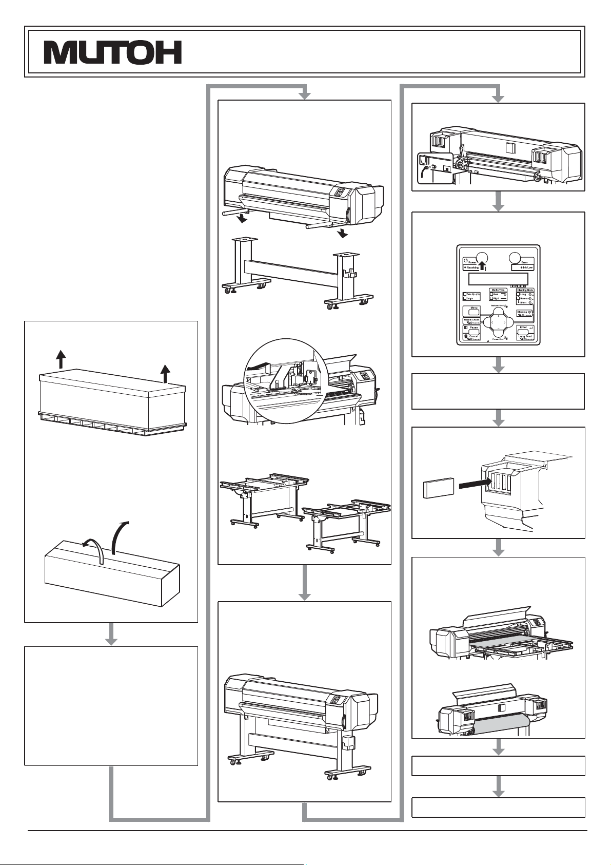
Installation flow chart
The broad steps for installation are shown below.
There are instructions for each section beginning on
the next page.
1 Unpacking boxes
VJ-1626UH INSTALLATION MANUAL
5
3 Assembling
3.1 Assembling the stand
3.2 Attaching the stand
Connecting the power cable
6
T urning the power ON/OFF
1.1 Unpacking the printer box
1.2 Unpacking the stand box and
the Media-feed table F and R
boxes
2
Confirming bundled items
3.3 Detaching fastening materials
3.5
Assembling the Media-feed table
(optional)
4 Installation
4.1 Installation environment
4.2 Installation procedure
7 Product activation
8 Initial ink filling
9
Loading media
9.1 Loading rigid media
2.1 Items in the printer box
2.2 Items in the accessory box
2.3 Items in the stand box
2.4 Items in the Media-feed
table
(optional)
box
9.2 Loading roll media
10
Checking the printing condition
11 Manual composition
1 VJ1626UHE-I-01
VJ-1626UH INSTALLATION MANUAL
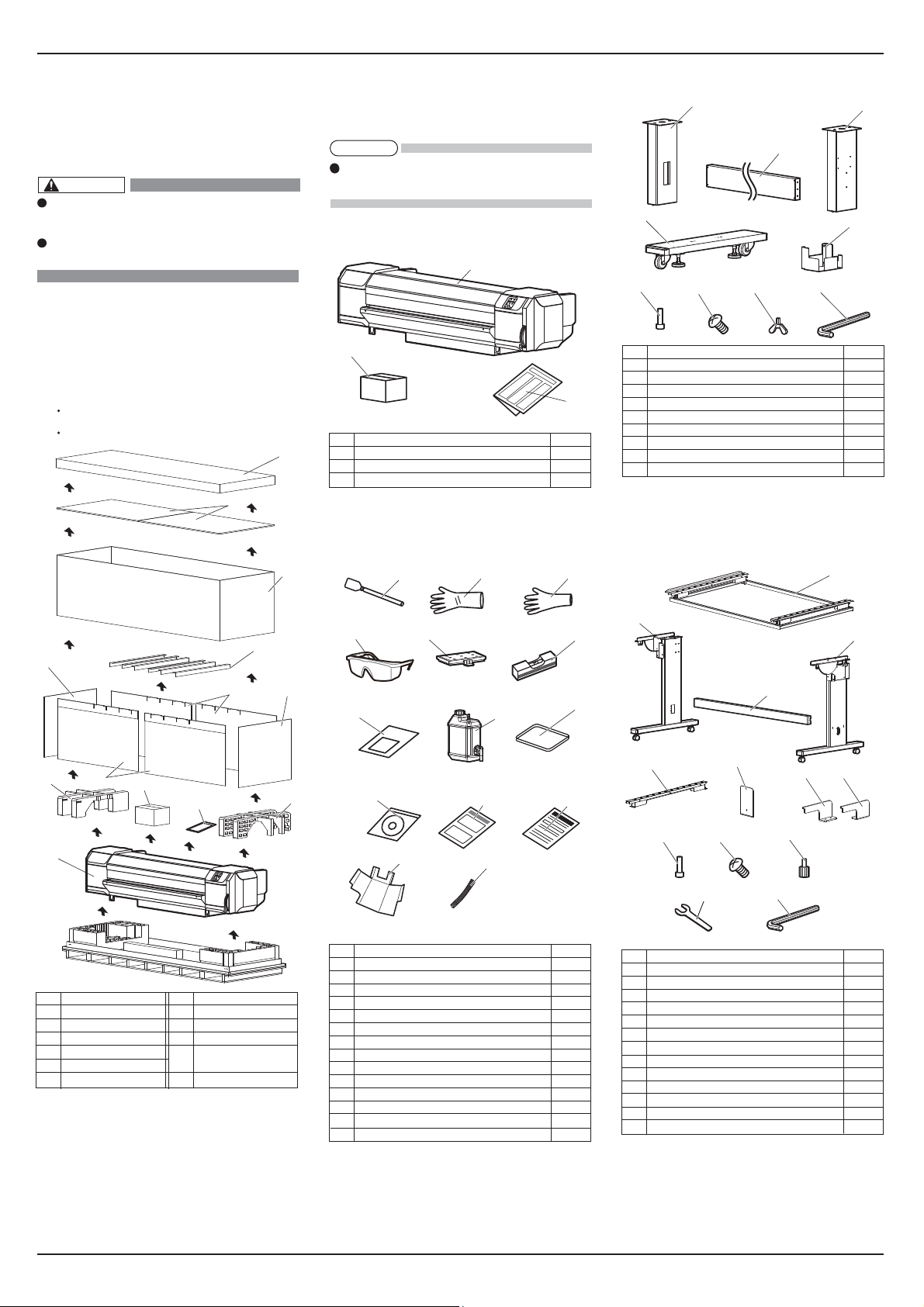
1 Unpacking boxes
Procedures for unpacking boxes are explained.
This printer package consists of four boxes: Main
body, Stands, and Media-feed table (two separate
optional boxes).
CAUTION
Make sure to unpack this product with
four persons or more.
While taking out the printer from the box,
make sure to remove the vinyl sheet.
1.1 Unpacking printer box
Unpack the printer box in accordance with the following steps.
1. Carry the box to where you will unpack it.
2. Remove the bands.
3. Open the box and take out the following components.
Printer main body
Accessory box
1
2
3
2
Confirming bundled items
After unpacking, please confirm that the product has
not damaged and no components are missing.
NOTE
If any items are damaged or missing, contact
MUTOH local dealer.
2.1
Items in the printer box
1
2
No. Name Q'ty
1 Printer main body 1 set
2 Accessory box 1
3 Installation Manual (this manual) 1
2.2
Items in the accessory box
12
2.3 Items in the stand box
1
3
4
6
No. Name Q'ty
1 Leg part (Right) 1
2 Leg part (Left) 1
3
3 Connector bar 1
4 Base parts 2
5 Waste fluid tank holder 1
6 Hexagon socket head cap screws 8
7 Waste fluid tank holder fixing screws 4
8 Butterfly screws 8
9 Hexagonal wrench 1
7
89
2
5
2.4 Contents of Media-feed table
(optional) box
3
(half side)
1
4
5
6
7
11
No. Name No. Name
1
2
3
4
5
6
6
Top cover
Top board
Outer board
Center board
Side board A
Side board B
9
10
7
Cushion (Left)
Cushion (Right)
8
Accessory box
9
Installation Manual
10
(this manual)
Printer main body
11
1.2 Unpacking Stand, Media-feed
table
Follow the procedure below to unpack the Stand,
Media-feed table F, and Media-feed table R.
*Media-feed tables F and R are optional.
1. Carry the box to where you will unpack it.
2. Open the box and take out the components.
4
5
7
8
10
No. Name Q'ty
1 Clean stick 10
2 Rubber gloves 100
3 Plastic gloves 100
4 Goggles 1
5 Flushing box sponge 10
6 Spirit level 1
7 Paper towel(Lint-free cloths) 5
8 Waste fluid tank 1
9 Tray 1
10 Operation Manual CD 1
11 Notes for using the dedicated ink 1
12 Notification sheet (Japanese/English) 1
13 Light-shielding cover 1
14 Light-shielding tube 1
5
13
6
8
11
14
9
12
2
3
4
5
9
No. Name Q'ty
1 Frames 1
2 Leg (left) 1
3 Leg (right) 1
4 Reinforcement 1
5 Rails (fixed) 1
6 Stopper 1
7 Installation plate (Left) 2
8 Installation plate (Right) 2
9 Hexagon socket head cap screw 8
10 Screw 8
11 Lug screw 1
12 Hexagonal spanner 2
13 Hexagonal wrench 1
6
10
12 13
7 8
11
VJ1626UHE-I-01 2

VJ-1626UH INSTALLATION MANUAL
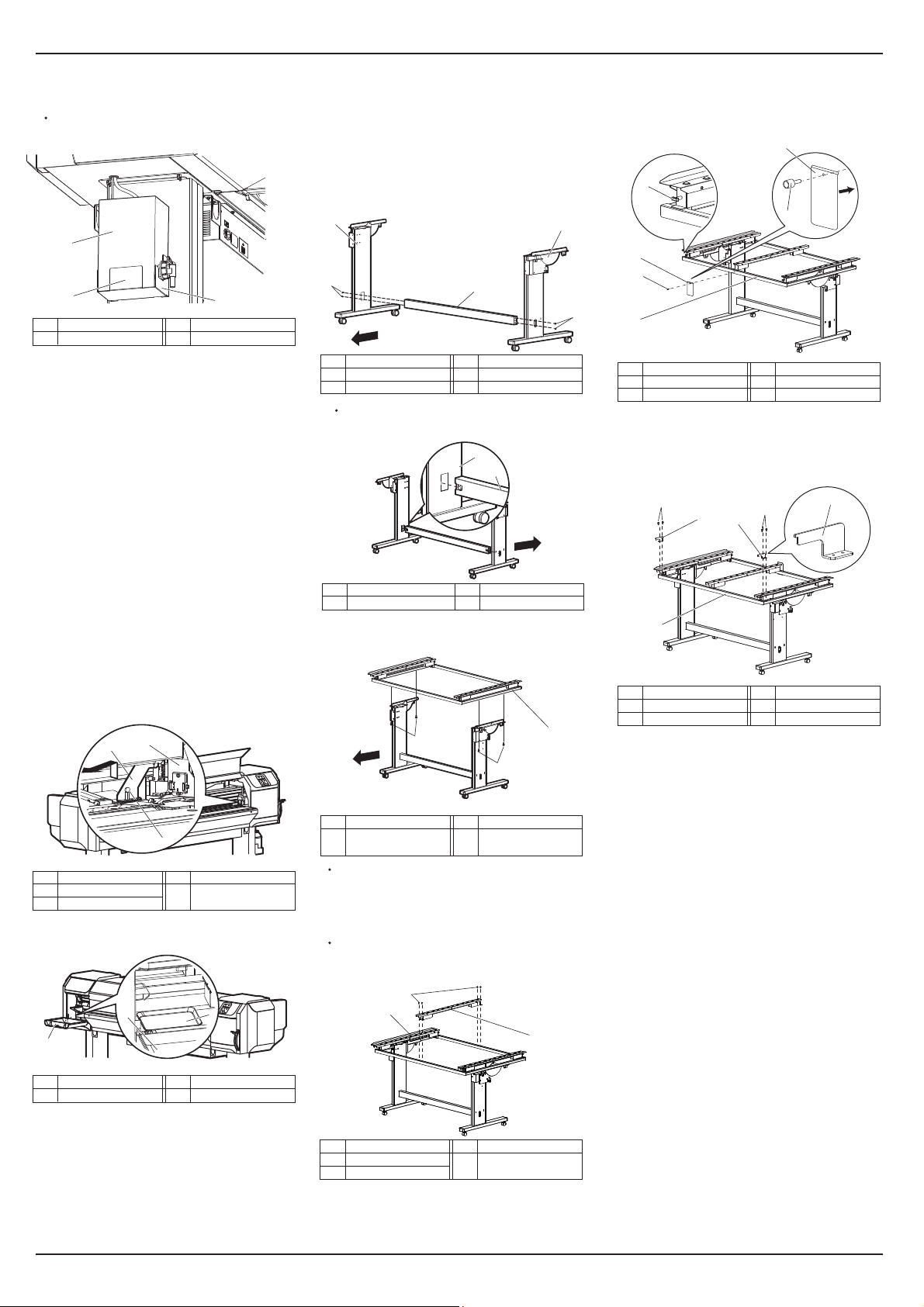
3 Assembling
This section explains how to assemble the printer.
CAUTION
Assemble this printer with 4 persons
or more.
3.1 Assembling the stand
Follow the procedure below to assemble the stand.
1. Follow the procedure below to assemble the right
stand.
a. Attach the right leg part to the right base part so
that four screw holes in the base part are at the front.
b.Tighten two hexagon socket head cap screws using a
hexagonal wrench.
1
Front
4
No. Name No. Name
1 Leg part (Right)
2 Base part
3
Hexagon socket head cap screws
4 Screw holes in base part
2. Assemble the left stand in the same way as in Step 1.
Front
4
2
3
1
2
4. Fasten the connector bar to the left stand in the
same way as in Step 3.
1
Front
3
No. Name No. Name
1 Stand (Left)
2 Connector bar
3 Hexagon socket head
2
cap screws
5. Attach the waste fluid tank holder to the right
stand using four waste fluid tank holder fixing
screws.
1
2
No. Name No. Name
1 Leg part (Right)
2 Waste fluid tank holde
3 Waste fluid tank holder
fixing screws
6. Shake the stand to make sure that each part is
firmly attached.
When the printer is wobbly, loosen the hexagon
socket head cap screws once and then tighten
them again.
3.2 Attaching the stand
Follow the procedure below to attach the stand to the
printer.
1. Turn the four adjusters as shown below to prevent
the stand from moving.
1
3. Remove the two transfer stays and fasten the
printer to the stand using eight butterfly screws.
1
2
3
3
No. Name No. Name
1 Transfer stays 3 Butterfly screws
2 Stand
1
3
2
3
3
2
3
4. Shape the light-shielding cover.
To shape the light-shielding cover, use doublesided adhesive tape (already attached to the
3
light-shielding cover) to glue each tab to the
corresponding side
2
2
1
No. Name No. Name
1 Light-shielding cover 3 Double-sided adhesive
tape (Flip side)
5. Attach the light-shielding tube to the waste fluid
tube.
Fix the light-shielding tube to the rubber bush.
3
2
2
1
1
1
3
No. Name No. Name
1 Leg part (Left)
2 Base part
Hexagon socket head cap screws
3
4 Screw holes in base part
3. Fasten the connector bar to the right stand using
No. Name No. Name
1 Adjusters
2 Stand
2. Insert the two transfer stays into the right and left
transfer brackets, lift the printer with four or more
people and place it on the stand.
two hexagon socket head cap screws.
Attach the connector bar with the groove facing
the rear as shown below.
1
2
Front
3
No. Name No. Name
1 Stand (Right)
2 Connector bar
3 VJ1626UHE-I-01
3
Hexagon socket head cap screws
4 Groove in connector bar
4
1
No. Name No. Name
1 Transfer stays
2 Transfer brackets
2
2
1
3
3 Stand
No. Name No. Name
1 Waste fluid tube 3 Rubber bush
2 Light-shielding tube
4. Follow the procedure below to attach the waste fluid
tank.
a. Place the waste fluid tank in the waste fluid tank
holder.
b. Attach the waste fluid tube to the tank.
c. Insert the waste fluid sensor cable into the
connector on the bottom of the printer.
3
5
4
2
1
No. Name No. Name
1 Waste fluid tank holder
2 Waste fluid tank
3 Waste fluid tube
4 Waste fluid sensor cable
Waste fluid sensor connector
5
VJ-1626UH INSTALLATION MANUAL
2
1
7. Attach the light-shielding cover to the waste fluid
tank.
Insert the light-shielding cover inside the waster
fluid tank holder.
1
2
No. Name No. Name
1 Light-shielding cover 2 Waste fluid tank holder
2
3.3 Detaching fastening materials
This printer has fastening materials in the place shown
below.
1. Remove all tapes from each cover.
3.4 Assembling the Media-feed table
(optional)
Follow the procedure below to assemble the
Media-feed table.
3.4.1
Assembling the Media-feed table
1. Use hexagon socket head cap screws (4 pieces) to
fix the reinforcement between the legs (right and
left).
1
4
3
Front
No. Name No. Name
1
2 Leg (right)
Leg (left)
4
Reinforcement
3
Hexagon socket head cap screws
Place the convex sections of the legs (right and left)
along the notch of the reinforcement to assemble.
2
Front
4. Use the lug screw to fix Stopper on Frame
・Install Stopper on the side of rail retaining screw.
・Install Stopper so that the curved part matches
Frame.
4
2
3
4
1
No. Name No. Name
1 Frame
2 Stopper
3 Lug screw
4 Rail retaining screw
5. Use the screws (2 pieces each) and fix Installation
plates (R and L) on Frame.
・Install Installation plates on the opposite side of rail
fixing screw.
3
1
3
2
2
3
1
2. Open the front cover and remove all protection
materials fixed with tape.
3. Open the right Maintenance cover, and remove all
the packing materials that are fixed with tape.
4. Remove a screw from the head unit fastening
material (metal plate) and remove the material.
1
3
2
No. Name No. Name
1
Head unit
2
Screw
Head unit fastening
3
material (metal plate)
5. Open the left maintenance cover, then place the tray.
1
1
2
No. Name No. Name
1 Leg (left), leg (right) 2 Reinforcement
2. Place the Frame on the legs and fix it with four
hexagon socket head cap screws.
1
Front
No. Name
1 Frame
2
2
No. Name
2 Hexagon socket head
cap screws
Firmly insert the protruding portions of the legs
to the holes of the Frame to fix it.
3. Use the screws (4 pieces) to fix Rails (fixed) on
the center of Frame.
When installing Rails (fixed), make sure that
the left and right rails are facing the same way.
3
2
1
3
No. Name No. Name
1 Installation plates (R)
2 Installation plates (L)
3 Frame
4 Screw
6. Assemble the other side of Media-feed table in the
same way
No. Name No. Name
1 Maintenance cover 2 Tray
1 Rails(fixed)
2 Frame
VJ1626UHE-I-01 4
No. Name No. Name
3 Screw
VJ-1626UH INSTALLATION MANUAL
4 Installation
Procedures and environment for installing this product
are explained.
4.1 Installation environment
Install this product to the appropriate place with
reference to the following.
WARNING
Do not install the printer in the
following places where there is a
possibility that the printer may be
damaged or might fall or be fallen by
chance.
On a shaky stand
Slanting location
Places where vibration of other
machines etc. is transmitted.
Do not step on the printer or place
heavy things on top of it.
It may cause an injury if the printer
falls down.
Do not block the vent by covering the
printer with cloths, such as a blanket or
tablecloth. If the vent is blocked, heat
may accumulate inside the printer and
it may cause fire.
Do not install the printer in a location
that has high humidity or is dusty.
It could lead to electric shock and fire.
4.1.1
Installation environmental condition
Select an installation location in accordance with the
table below.
Floor strength of
installation place
Power
Rated
voltage
Specification
Frequency
Range
Power
capacity
Operative
Environm-
condition
ental
conditions
Printing
accuracy
coverage
Change
rate within
warranty
NOTE
For temperature and humidity, avoid locations
such as the following. There is a possibility that
the print quality will be affected.
Places where temperature or humidity may
rapidly change, even though within the required
conditions.
Places that receive direct sunlight, increased
illumination or direct air, for example from an air
conditioner.
To keep the temperature and humidity constant,
install this product in a location where the air
condition is adjustable.
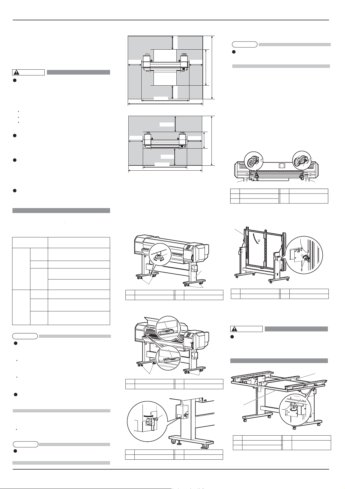
4.1.2 Installation space
Install on a level floor which meets the following condition.
It has enough strength to support the weight of the
printer and the stand.
NOTE
For the weight of the printer and the stand, refer to
the Operation Manual.
More than 2940 Pa (300 kg/m2)
AC100-240V
50/60Hz ± 1Hz
100V-120V: Total of 4.0A
200V-240V: Total of 2.0A
Temperature: 20 °C to 32 °C
Humidity: 40 % to 60 %, No Condensation
Temperature: 22 °C to 30 °C
Humidity: 40 % to 60 %
Without condensation
Temperature: within 2 °C per hour
Humidity: within 5 % per hour
(1) When using the Media-feed table
1,000mm 1,000mm
1,000mm1,000mm
2,698mm
4,698mm
When not using the Media-feed table
(2)
1,000mm
1,000mm
1,000mm
2,698mm
4,698mm
1,000mm
2,730mm
818mm
4.2 Installation procedure
Install this product to the installation place in
accordance with the list shown below.
4.2.1 Installing the printer main unit
1. Carry the printer to the installation place.
2. Turn the following adjusters in the direction as
shown below to prevent the printer from moving.
Stands: adjusters (4)
1
2
1
No. Name No. Name
1 Adjuster 2 Stand
3. Set the level on the right and left platens and
adjust so that the printer stays flat.
1
1
No. Name No. Name
1 Level 2 Adjuster
2
4. Confirm that the waste fluid valve is closed.
1
No. Name No. Name
1 Waste fluid valve
1
2
4.2.2 Installing the Media-feed tables
(optional)
NOTE
When Using the roll media for “10 Checking the
4,730mm
printing condition”, you do not need to install
Media-feed table.
When using rigid media on this printer, use
Media-feed table (optional).
Follow the procedure below to install Media-feed
table.
The following items are required for installing
Media-feed table:
• Spanner: Accessories for Media-feed table
• Level: provided with the printer
2,818mm
(1)Rear side
1. Loosen the fixing levers on the right and left side
of the rear. Set the distance between the roll media
holders wider than the roll media width.
3
1
1
No. Name No. Name
1 Roll media holder(L)
2 Roll media holder(R)
3 Fixing Lever
2. Loosen retaining screws of Media-feed table, and
slowly level the table.
1
No. Name No. Name
1 Media-feed table 2 Leveling screw
3. Tighten the leveling screws of Media-feed table (2
places, both sides), and fix the table.
WARNING
When fixing the leveling screws, hold
the frame while pressuring the rubber
foot, and then turn the
screw until it doesn't turn any further.
3
No. Name No. Name
1 Media-feed table
2 Leveling screw
3 Frame
2
3
2
2
1
2
5 VJ1626UHE-I-01
 Loading...