

Page 1
MAINTENANCE
MANUAL
Full-ColorInkjetPrinter
VJ-1324
VJ1324E-M-02
Page 2

General Table of Contents VJ1324E-M-02
1 Safety Instruction
1.1 Introduction . . . . . . . . . . . . . . . . . . . . . . . . . . . . . . . . . . . . 1-2
1.1.1 Types and Meanings of Warnings . . . . . . . . . . . . . . . . 1-2
1.2 Warning Labels . . . . . . . . . . . . . . . . . . . . . . . . . . . . . . . . . 1-2
1.2.1 Handling the Warning Labels. . . . . . . . . . . . . . . . . . . . 1-2
1.2.2 Location and Type of Warning Labels . . . . . . . . . . . . . 1-2
2 Trouble Shooting
2.1 Introduction . . . . . . . . . . . . . . . . . . . . . . . . . . . . . . . . . . . . 2-2
2.2 Troubleshooting with Error Messages. . . . . . . . . . . . . . . 2-7
2.2.1 Operation Status . . . . . . . . . . . . . . . . . . . . . . . . . . . . . 2-7
2.2.2 Errors with Message . . . . . . . . . . . . . . . . . . . . . . . . . . 2-9
2.2.3 Errors Requiring Reboot . . . . . . . . . . . . . . . . . . . . . . 2-15
2.2.4 Error Messages During File Transmission. . . . . . . . . 2-32
2.3 Troubleshooting Without Error Messages . . . . . . . . . . 2-35
2.3.1 Initial Operation Problems . . . . . . . . . . . . . . . . . . . . . 2-35
2.3.2 Media Feed Problems . . . . . . . . . . . . . . . . . . . . . . . . 2-41
2.3.3 Printing Problems . . . . . . . . . . . . . . . . . . . . . . . . . . . 2-44
2.3.4 Noise Problems . . . . . . . . . . . . . . . . . . . . . . . . . . . . . 2-57
2.3.5 Media Cutting Problems. . . . . . . . . . . . . . . . . . . . . . . . . . 2-60
2.3.6 Online Function Problems . . . . . . . . . . . . . . . . . . . . . 2-63
2.3.7 Other Problems . . . . . . . . . . . . . . . . . . . . . . . . . . . . . 2-65
2.3.8 Problems in Using MUTOH Service Assistance . . . . 2-67
3 Parts Replacement
3.1 Introduction . . . . . . . . . . . . . . . . . . . . . . . . . . . . . . . . . . . . 3-5
3.2 Removing Covers. . . . . . . . . . . . . . . . . . . . . . . . . . . . . . . . 3-6
3.2.1 Removing I/H Cover . . . . . . . . . . . . . . . . . . . . . . . . . . 3-7
3.2.2 Remove Side Cover R . . . . . . . . . . . . . . . . . . . . . . . . . 3-8
3.2.3 Removing Side Cover L and Replacing Maintenance
Cover Holder 3-11
3.2.4 Removing Front Cover and Replacing Front Cover Holder
3-13
3.2.5 Removing Paper Guide F(Upper) . . . . . . . . . . . . . . . 3-14
3.2.6 Removing Top Cover . . . . . . . . . . . . . . . . . . . . . . . . 3-16
3.2.7 Removing Paper Guide R2 . . . . . . . . . . . . . . . . . . . 3-17
3.2.8 Removing Scroller Holder (L, R) . . . . . . . . . . . . . . . . 3-18
3.2.9 Assembling of Scroller Holder L and R . . . . . . . . . . . 3-19
3.3 Replacing Cover Peripherals . . . . . . . . . . . . . . . . . . . . . 3-21
3.3.1 Replacing Panel Unit . . . . . . . . . . . . . . . . . . . . . . . . . 3-21
3.3.2 Replacing Panel FFC (Panel tape wires). . . . . . . . . . 3-22
3.3.3 Replacing Cover Switch Assy、 Sensor Cover L Assy,
Sensor Cover R Assy 3-25
3.3.4 Replacing Cover L Cable Assy . . . . . . . . . . . . . . . . . 3-32
3.3.5 Replacing Cover R Cable Assy. . . . . . . . . . . . . . . . . 3-35
3.4 Replacing Board Base . . . . . . . . . . . . . . . . . . . . . . . . . . . 3-36
3.4.1 Removing Connector Panel . . . . . . . . . . . . . . . . . . . . 3-37
3.4.2 Replacing Cooling FAN 24V Assy (For MAIN Board) 3-38
3.4.3 Removing MAIN Board Bracket . . . . . . . . . . . . . . . . . 3-39
3.4.4 Replacing MAIN Board Assy . . . . . . . . . . . . . . . . . . . 3-42
3.4.5 Replacing SODIMM . . . . . . . . . . . . . . . . . . . . . . . . . . 3-43
3.4.6 Removing Controller Board Bracket . . . . . . . . . . . . . 3-44
3.4.7 Replacing HEATER CONT Board Assy. . . . . . . . . . . 3-46
3.4.8 Replacing HEATER RELAY Board Assy . . . . . . . . . . 3-47
3.4.9 Remove Power Board Bracket. . . . . . . . . . . . . . . . . . 3-48
3.4.10 Replacing Power Board Assy . . . . . . . . . . . . . . . . . . 3-50
3.4.11 Replacing JUNCTION Board Assy . . . . . . . . . . . . . . 3-51
3.4.12 Replacing JUNC_FFC . . . . . . . . . . . . . . . . . . . . . . . . 3-53
3.4.13 Replace JUNC_ID Cable Assy . . . . . . . . . . . . . . . . . 3-55
General Table of Contents P.1
Page 3

General Table of Contents VJ1324E-M-02
3.4.14 Cooling FAN (24V) Assy、 Cooling Fan Cable Assy 3-56
3.4.15 Replacing AC Inlet、 AC Cable Noise Filter-Fuse Assy、
Noise Filter FG_Assy 3-58
3.4.16 Other Cable Assy and Serial Cable Assy . . . . . . . . . 3-59
3.4.17 Replace Power Cable CNT-RLY Assy. . . . . . . . . . . . 3-60
3.5 Replacement of PF Driving Section Components . . . . 3-61
3.5.1 Replace PF Motor Assy . . . . . . . . . . . . . . . . . . . . . . . 3-61
3.5.2 Replacing PF Motor Relay Assy . . . . . . . . . . . . . . . . 3-64
3.5.3 Replacing PF Encoder Assy . . . . . . . . . . . . . . . . . . . 3-65
3.5.4 Replacing PF Encoder Scale. . . . . . . . . . . . . . . . . . . 3-66
3.5.5 Replacing X speed reduction belt 、 Speed reduction
Pulley 3-67
3.5.6 Replacing Heater Section . . . . . . . . . . . . . . . . . . . . . 3-71
3.6 Replacing CR Driving Section Components . . . . . . . . . 3-86
3.6.1 Replacing CR Motor Assy . . . . . . . . . . . . . . . . . . . . . 3-86
3.6.2 Replacing CR Motor Cable Assy . . . . . . . . . . . . . . . . 3-88
3.6.3 Replacing CR_HP sensor . . . . . . . . . . . . . . . . . . . . . 3-89
3.6.4 Replacing CR Origin Sensor Cable Assy . . . . . . . . . 3-90
3.6.5 Replacing Lever Sensor . . . . . . . . . . . . . . . . . . . . . . 3-91
3.6.6 Replacing Lever Sensor Cable Assy . . . . . . . . . . . . . 3-92
3.6.7 Replacing T Fence, T Fence Spring Assy . . . . . . . . . 3-93
3.6.8 Replacing CR Return Pulley Assy, CR Belt RJ13Assy . 395
3.6.9 Replacing Pressure roller Arm Assy . . . . . . . . . . . . . 3-97
3.7.6 Replacing Print Head . . . . . . . . . . . . . . . . . . . . . . . . 3-106
3.7.7 Replacing Solenoid Head Assy . . . . . . . . . . . . . . . . 3-111
3.7.8 Replacing Ink Tube . . . . . . . . . . . . . . . . . . . . . . . . . 3-116
3.7.9 Replacing Y Fitting. . . . . . . . . . . . . . . . . . . . . . . . . . 3-123
3.7.10 Replacing Head FFC . . . . . . . . . . . . . . . . . . . . . . . . 3-124
3.7.11 Replacing Cutter Solenoid Cable Assy . . . . . . . . . . 3-125
3.7.12 Replacing CR Encoder Assy . . . . . . . . . . . . . . . . . . 3-126
3.7.13 Replacing Photometer JUNCTION Board Assy. . . . 3-128
3.7.14 Removing Cutter Holder . . . . . . . . . . . . . . . . . . . . . 3-131
3.7.15 Replacing Cutter Solenoid Assy, Cutter Solenoid Spring
Assy 3-133
3.7.16 Replacing P_EDGE Sensor Assy . . . . . . . . . . . . . . 3-135
3.7.17 Replacing Head FG_Assy . . . . . . . . . . . . . . . . . . . . 3-137
3.8 Replacing Maintenance Section . . . . . . . . . . . . . . . . . . 3-138
3.8.1 Replacing Maintenance Assy. . . . . . . . . . . . . . . . . . 3-138
3.8.2 Replacing PumpMotor Relay Assy . . . . . . . . . . . . . 3-141
3.8.3 Replacing Cap Head Assy . . . . . . . . . . . . . . . . . . . . 3-142
3.8.4 Replacing Waste Fluid Sensor Cable Assy . . . . . . 3-143
3.8.5 Replacing Wiper Assy . . . . . . . . . . . . . . . . . . . . . . . 3-144
3.8.6 Replacing Wiper Origin Sensor Cable Assy . . . . . . 3-145
3.9 Replacing Ink Supply Section Components . . . . . . . . 3-146
3.9.1 Replacing Cartridge Holder Assy. . . . . . . . . . . . . . . 3-146
3.9.2 Replacing Ink ID Board Assy、 Pressure Roller Holder
Spring Assy 3-148
3.7 Replacing Carriage Peripherals . . . . . . . . . . . . . . . . . . . 3-98
3.7.1 How To Release Carriage Lock. . . . . . . . . . . . . . . . . 3-98
3.7.2 Removing Carriage Cover . . . . . . . . . . . . . . . . . . . . . 3-99
3.7.3 Removing CR Board Cover . . . . . . . . . . . . . . . . . . . 3-100
3.7.4 Replacing CR Board Assy . . . . . . . . . . . . . . . . . . . . 3-101
3.10 Replacement of Frame Section Components . . . . . . . 3-149
3.10.1 Replacing Adsorption FAN. . . . . . . . . . . . . . . . . . . . 3-149
3.10.2 Replacing P_REAR Sensor . . . . . . . . . . . . . . . . . . 3-150
3.10.3 Replacing Lock Arm Assy, Lock Arm Spring Assy, Arm
Axis Assy 3-151
3.7.5 Replacing Carriage Assy . . . . . . . . . . . . . . . . . . . . . 3-102
3.11 Replacing Cable Guide Section Components . . . . . . . 3-152
General Table of Contents P.2
Page 4

General Table of Contents VJ1324E-M-02
3.11.1 Replacing Tube Fixing Clamp . . . . . . . . . . . . . . . . . 3-152
3.11.2 Replace Steel Bare . . . . . . . . . . . . . . . . . . . . . . . . . 3-153
3.11.3 Replacing CR_FFC. . . . . . . . . . . . . . . . . . . . . . . . . 3-154
3.11.4 Replace Valve Solenoid
(Exploded View CR Assy2) 3-158
3.11.5 Replace Solenoid Tube Assy. . . . . . . . . . . . . . . . . . 3-160
3.12 Replacing Accessory Unit . . . . . . . . . . . . . . . . . . . . . . . 3-161
3.12.1 Replacing Waste Fluid Level Switch ,Waste Fluid Bottle
Assy 3-161
3.13 Replacing Take-Up Unit (Option) . . . . . . . . . . . . . . . . . 3-162
3.13.1 Removing Tension Arm . . . . . . . . . . . . . . . . . . . . . . 3-162
3.13.2 Removing Take-Up Unit . . . . . . . . . . . . . . . . . . . . . 3-164
3.13.3 Removing Take-Up Unit Cover . . . . . . . . . . . . . . . . 3-165
3.13.4 Replacing Scroller . . . . . . . . . . . . . . . . . . . . . . . . . . 3-166
3.13.5 Replacing Take-Up Unit Control Board Assy. . . . . . 3-169
3.13.6 Replacing Take-Up ON Sensor and Take-Up OFF Sensor
3-176
3.13.7 Replacing Peripheral Devices of VJ Take-Up Unit Motor
Assy 3-179
4.5.1 Adjustment Procedure . . . . . . . . . . . . . . . . . . . . . . . . . 4-8
4.6 CR Belt Tension Adjustment. . . . . . . . . . . . . . . . . . . . . . 4-10
4.7 Head Accuracy Adjustment. . . . . . . . . . . . . . . . . . . . . . . 4-11
4.7.1 Head Alignment (Horizontal Height) . . . . . . . . . . . . . 4-11
4.7.2 Head Alignment (Vertical Slant). . . . . . . . . . . . . . . . . 4-13
4.8 Cutter Holder Height Adjustment . . . . . . . . . . . . . . . . . . 4-15
4.8.1 Jigs and Tools . . . . . . . . . . . . . . . . . . . . . . . . . . . . . . 4-15
4.8.2 Adjustment Procedure . . . . . . . . . . . . . . . . . . . . . . . . 4-15
4.9 Head Height Adjustment . . . . . . . . . . . . . . . . . . . . . . . . . 4-16
4.9.1 Jigs and Tools . . . . . . . . . . . . . . . . . . . . . . . . . . . . . . 4-16
4.9.2 Adjustment Procedure . . . . . . . . . . . . . . . . . . . . . . . . 4-16
4.10 Capping Position Adjustment . . . . . . . . . . . . . . . . . . . . . 4-18
4.11 Cover Switch Sensor Assy Position Adjustment . . . . . 4-20
4.12 Rear/ Edge Sensor Adjustment. . . . . . . . . . . . . . . . . . . . 4-21
4.13 Cutter position adjustment . . . . . . . . . . . . . . . . . . . . . . . 4-23
4 Adjustment
4.1 Introduction . . . . . . . . . . . . . . . . . . . . . . . . . . . . . . . . . . . . 4-2
4.2 Adjustment Item . . . . . . . . . . . . . . . . . . . . . . . . . . . . . . . . . 4-2
5 Self-Diagnosis Mode
5.1 Introduction. . . . . . . . . . . . . . . . . . . . . . . . . . . . . . . . . . . . . 5-3
5.2 Preparation . . . . . . . . . . . . . . . . . . . . . . . . . . . . . . . . . . . . . 5-3
5.2.1 Preparations on Machine . . . . . . . . . . . . . . . . . . . . . . . 5-3
4.3 Working with MUTOH Service Assistance Software . . . 4-4
4.4 X Speed Reduction Belt Tension Adjustment . . . . . . . . . 4-5
4.4.1 Jigs and Tools . . . . . . . . . . . . . . . . . . . . . . . . . . . . . . . 4-5
4.4.2 Adjustment Procedure . . . . . . . . . . . . . . . . . . . . . . . . . 4-6
4.5 PF Encoder Assy Position Adjustment . . . . . . . . . . . . . . 4-8
General Table of Contents P.3
5.2.2 Starting Up . . . . . . . . . . . . . . . . . . . . . . . . . . . . . . . . . . 5-3
5.3 Operations in Self-Diagnosis Mode . . . . . . . . . . . . . . . . . 5-4
5.3.1 Operating Self-Diagnosis Mode. . . . . . . . . . . . . . . . . . 5-4
5.3.2 Diagnosis Items in Self-Diagnosis Menu . . . . . . . . . . . 5-5
5.4 Platen Adjustment Menu . . . . . . . . . . . . . . . . . . . . . . . . . . 5-6
Page 5

General Table of Contents VJ1324E-M-02
5.5 Inspection Menu. . . . . . . . . . . . . . . . . . . . . . . . . . . . . . . . . 5-7
5.5.1 Ram Capacity Menu . . . . . . . . . . . . . . . . . . . . . . . . . . 5-9
5.5.2 Version Menu. . . . . . . . . . . . . . . . . . . . . . . . . . . . . . . 5-10
5.5.3 Panel Menu . . . . . . . . . . . . . . . . . . . . . . . . . . . . . . . . 5-11
5.5.4 Sensor Menu . . . . . . . . . . . . . . . . . . . . . . . . . . . . . . . 5-12
5.5.5 Cut Solenoid Menu . . . . . . . . . . . . . . . . . . . . . . . . . . 5-14
5.5.6 Choke Valve Menu . . . . . . . . . . . . . . . . . . . . . . . . . . 5-15
5.5.7 Encoder Menu . . . . . . . . . . . . . . . . . . . . . . . . . . . . . . 5-16
5.5.8 Fan Menu. . . . . . . . . . . . . . . . . . . . . . . . . . . . . . . . . . 5-17
5.5.9 Record Menu . . . . . . . . . . . . . . . . . . . . . . . . . . . . . . . 5-18
5.5.10 Head Signal Menu . . . . . . . . . . . . . . . . . . . . . . . . . . . 5-24
5.5.11 Spectro Vue Menu . . . . . . . . . . . . . . . . . . . . . . . . . . . 5-25
5.5.12 Time Check Menu . . . . . . . . . . . . . . . . . . . . . . . . . . . 5-26
5.6 Ink Charging Menu. . . . . . . . . . . . . . . . . . . . . . . . . . . . . . 5-27
5.7 Adjustment Menu . . . . . . . . . . . . . . . . . . . . . . . . . . . . . . . 5-28
5.7.1 Rear/ Edge Sensor Adjustment . . . . . . . . . . . . . . . . . 5-30
5.7.2 CR Return Position adjustment . . . . . . . . . . . . . . . . . 5-32
5.7.3 Head Nozzle Check Menu . . . . . . . . . . . . . . . . . . . . . 5-33
5.7.4 Skew Check Menu. . . . . . . . . . . . . . . . . . . . . . . . . . . 5-36
5.7.5 Head Slant Check Menu . . . . . . . . . . . . . . . . . . . . . . 5-37
5.7.6 Uni-D/Bi-D Adjustment Menu. . . . . . . . . . . . . . . . . . . 5-42
5.7.7 Bi-D Copy . . . . . . . . . . . . . . . . . . . . . . . . . . . . . . . . . 5-49
5.7.8 Top&Bottom adjustment Menu . . . . . . . . . . . . . . . . . 5-50
5.7.9 Test Printing Menu. . . . . . . . . . . . . . . . . . . . . . . . . . . 5-51
5.7.10 Longstore Menu. . . . . . . . . . . . . . . . . . . . . . . . . . . . . 5-53
5.7.11 Software Counter Initialization Menu . . . . . . . . . . . . . 5-54
5.7.12 Feed Pitch Check Menu . . . . . . . . . . . . . . . . . . . . . . 5-55
5.7.13 Solid Print Menu . . . . . . . . . . . . . . . . . . . . . . . . . . . . 5-56
5.8 Cleaning Menu. . . . . . . . . . . . . . . . . . . . . . . . . . . . . . . . . 5-57
5.9 Sample Printing Menu . . . . . . . . . . . . . . . . . . . . . . . . . . . 5-58
5.10 Parameter Menu . . . . . . . . . . . . . . . . . . . . . . . . . . . . . . . . 5-59
5.10.1 Parameter Initialization Menu . . . . . . . . . . . . . . . . . . 5-59
5.10.2 Parameter Update Menu . . . . . . . . . . . . . . . . . . . . . . 5-61
5.11 Servo Setting Menu . . . . . . . . . . . . . . . . . . . . . . . . . . . . . 5-70
5.12 Endurance Running Menu . . . . . . . . . . . . . . . . . . . . . . . . 5-71
5.12.1 CR Motor Assy Endurance Menu . . . . . . . . . . . . . . . 5-72
5.12.2 PF Motor Assy Endurance Menu . . . . . . . . . . . . . . . 5-73
5.12.3 Cutter Endurance Menu. . . . . . . . . . . . . . . . . . . . . . . 5-74
5.12.4 Pump Endurance Menu . . . . . . . . . . . . . . . . . . . . . . . 5-75
5.12.5 Head Lock Menu . . . . . . . . . . . . . . . . . . . . . . . . . . . . 5-76
5.12.6 Choke Valve Menu. . . . . . . . . . . . . . . . . . . . . . . . . . . 5-77
5.12.7 Print Head Endurance (Nozzle Print) Menu. . . . . . . . 5-78
5.12.8 General Endurance Menu . . . . . . . . . . . . . . . . . . . . . 5-79
5.12.9 Endurance Running Check Menu . . . . . . . . . . . . . . . 5-80
5.13 Media Feed Menu . . . . . . . . . . . . . . . . . . . . . . . . . . . . . . . 5-81
5.14 ExControl Menu . . . . . . . . . . . . . . . . . . . . . . . . . . . . . . . . 5-82
5.14.1 Version Menu. . . . . . . . . . . . . . . . . . . . . . . . . . . . . . . 5-83
5.14.2 Sensor Menu . . . . . . . . . . . . . . . . . . . . . . . . . . . . . . . 5-84
5.14.3 Heater Menu . . . . . . . . . . . . . . . . . . . . . . . . . . . . . . . 5-85
5.15 PaperInitial Menu . . . . . . . . . . . . . . . . . . . . . . . . . . . . . . . 5-86
6 Maintenance Mode 2
6.1 Introduction. . . . . . . . . . . . . . . . . . . . . . . . . . . . . . . . . . . . . 6-2
6.2 Operations in Maintenance Mode 2 . . . . . . . . . . . . . . . . . 6-2
6.2.1 Starting Up the Maintenance Mode 2 . . . . . . . . . . . . . 6-2
6.2.2 Operating Maintenance Mode 2. . . . . . . . . . . . . . . . . . 6-3
6.3 Maintenance Mode 2 Menu . . . . . . . . . . . . . . . . . . . . . . . . 6-4
General Table of Contents P.4
Page 6

General Table of Contents VJ1324E-M-02
6.3.1 Counter Indication Menu . . . . . . . . . . . . . . . . . . . . . . . 6-5
6.3.2 Counter Initialization Menu . . . . . . . . . . . . . . . . . . . . 6-11
6.3.3 Counter Print Menu . . . . . . . . . . . . . . . . . . . . . . . . . . 6-12
6.3.4 Paper Feed Menu . . . . . . . . . . . . . . . . . . . . . . . . . . . 6-13
7 Maintenance
7.1 Introduction . . . . . . . . . . . . . . . . . . . . . . . . . . . . . . . . . . . . 7-2
7.2 Periodical Services . . . . . . . . . . . . . . . . . . . . . . . . . . . . . . 7-3
7.2.1 Periodic Replacement Parts . . . . . . . . . . . . . . . . . . . . 7-3
7.2.2 Parts Which Require Inspection/Replacement . . . . . . 7-4
7.3 Part Life Information . . . . . . . . . . . . . . . . . . . . . . . . . . . . . 7-5
7.4 Jigs and Tools . . . . . . . . . . . . . . . . . . . . . . . . . . . . . . . . . . 7-6
7.4.1 Required Tools . . . . . . . . . . . . . . . . . . . . . . . . . . . . . . 7-6
7.5 Lubrication/Bonding . . . . . . . . . . . . . . . . . . . . . . . . . . . . . 7-7
7.6 Transportation of Product. . . . . . . . . . . . . . . . . . . . . . . . . 7-8
9 Specifications
9.1 Introduction. . . . . . . . . . . . . . . . . . . . . . . . . . . . . . . . . . . . . 9-2
9.2 Product Specifications. . . . . . . . . . . . . . . . . . . . . . . . . . . . 9-2
9.2.1 Main Unit Specifications . . . . . . . . . . . . . . . . . . . . . . . 9-2
9.3 Interface Specifications . . . . . . . . . . . . . . . . . . . . . . . . . . . 9-3
9.3.1 Network Interface Specifications . . . . . . . . . . . . . . . . . 9-3
9.4 Options/Supplies List. . . . . . . . . . . . . . . . . . . . . . . . . . . . . 9-3
9.4.1 Supplies . . . . . . . . . . . . . . . . . . . . . . . . . . . . . . . . . . . . 9-3
9.5 Choosing a Place for the Printer . . . . . . . . . . . . . . . . . . . 9-4
10 Appendix
10.1 Introduction. . . . . . . . . . . . . . . . . . . . . . . . . . . . . . . . . . . . 10-2
10.2 Maintenance Part List . . . . . . . . . . . . . . . . . . . . . . . . . . . 10-2
8 Product Overview
8.1 Introduction . . . . . . . . . . . . . . . . . . . . . . . . . . . . . . . . . . . . 8-2
8.2 Part Names and Functions . . . . . . . . . . . . . . . . . . . . . . . . 8-2
8.2.1 Front Section . . . . . . . . . . . . . . . . . . . . . . . . . . . . . . . . 8-2
8.2.2 Rear Section . . . . . . . . . . . . . . . . . . . . . . . . . . . . . . . . 8-3
8.2.3 Operation Panel. . . . . . . . . . . . . . . . . . . . . . . . . . . . . . 8-4
8.3 Printer Status . . . . . . . . . . . . . . . . . . . . . . . . . . . . . . . . . . . 8-7
8.3.1 Operating Status Type. . . . . . . . . . . . . . . . . . . . . . . . . 8-7
8.3.2 Switching Operating Status . . . . . . . . . . . . . . . . . . . . . 8-8
8.3.3 Selecting Panel Language. . . . . . . . . . . . . . . . . . . . . 8-10
General Table of Contents P.5
Page 7
Important Notice VJ1324E-M-02
Important Notice
1. For Users in Europe
Important:
This is a Class A product approved for industrial environments. In a domestic environment this product may cause
radio interference in which case you may be required to take
adequate measures.
2. For Users in the United States
This equipment has been tested and found to comply with the limits for a Class A digital device,
pursuant to Part 15 of the FCC Rules. These limits are designed to provide reasonable protection
against harmful interference when the equipment is operated in a commercial environment.
This equipment generates, uses, and can radiate radio frequency energy and, if not installed and
used in accordance with the instruction manual, may cause harmful interference to radio
communications. Operation of this equipment in a residential area is likely to cause harmful
interference in which case the user will be required to correct the interference at his own expense.
3. Trademark Mentioned in this Manual
• MUTOH, ValueJet, VJ-1324 are registered trademarks or product names of MUTOH
INDUSTRIES LTD.
• Windows95, Windows98, Windows98SE, Windows NT4.0, Windows2000, Windows XP, and
MS-DOS are registered trademarks or product names of Microsoft Corporation.
• Intel and Pentium are trademarks or registered trademarks of Intel Corporation.
• Other company and product names may be registered trademarks or product names.
Warranty Limitations
1. MUTOH INDUSTRIES LTD. warrants part repair or replacement as a sole measure only if a
failure is found in the system or in the materials and workmanship of the product the seller
produced.
However, if the cause of failure is uncertain, decide the action after due mutual consultation.
2. The warranty shall not apply to any direct or indirect loss, or compensation for the loss due to the
product that has been subject to misuse, neglect, or improper alternation.
3. The warranty period is described in the warranty certificate.
• No part of this product or publication may be reproduced, copied, or transmitted
in any form or by any means, except for personal use, without the permission of
MUTOH INDUSTRIES LTD.
• The product and the contents of this publication may be changed without prior
notification.
• MUTOH INDUSTRIES LTD. has made the best efforts to keep this publication
free from error, but if you find any uncertainties or misprints, please call us or the
shop where you bought this equipment.
• MUTOH INDUSTRIES LTD. shall not be liable for any damages or troubles
resulting from the use of this equipment or this manual.
P.1
Page 8
About this Manual VJ1324E-M-02
About this Manual
1. Purpose and Target Readers
This manual explains preparations needed before maintaining and checking operations for
MUTOH Full Color Ink Jet Printer (VJ-1324).
This manual is prepared for the maintenance personnel of this printer.
Before using this printer, fully understand the contents and directions in this manual.
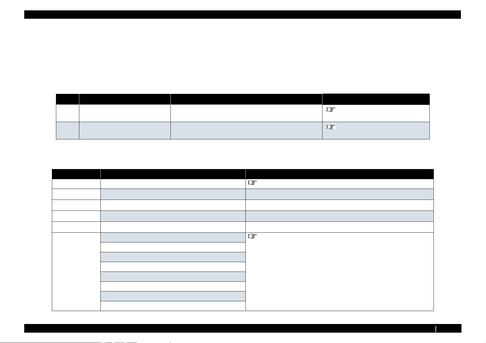
2. Manual Configuration
Section Contents
1 Safety Instructions Explains types of warnings, cautions and warnings labeled on the printer
for the both operators of the printer and maintenance personnel.
2 Troubleshooting Explains troubles that may occur when using the printer and how to solve
them.
3 Parts Replacement Explains the procedures of replacement and removal of the service parts
of the printer.
4 Adjustment Explains the adjusting procedures of the printer parts.
5 Self-Diagnostic Mode Explains the self-diagnostic functions of the printer.
6 Maintenance Mode 2 Explains the maintenance mode2 of the printer.
7 Maintenance Explains daily maintenance of the printer.
8 Product Overview Explains the features, part names, and functions of the printer.
9 Specifications Explains the specifications of the printer.
10 Appendix Explains the maintenance information and the exploded views for this
printer.
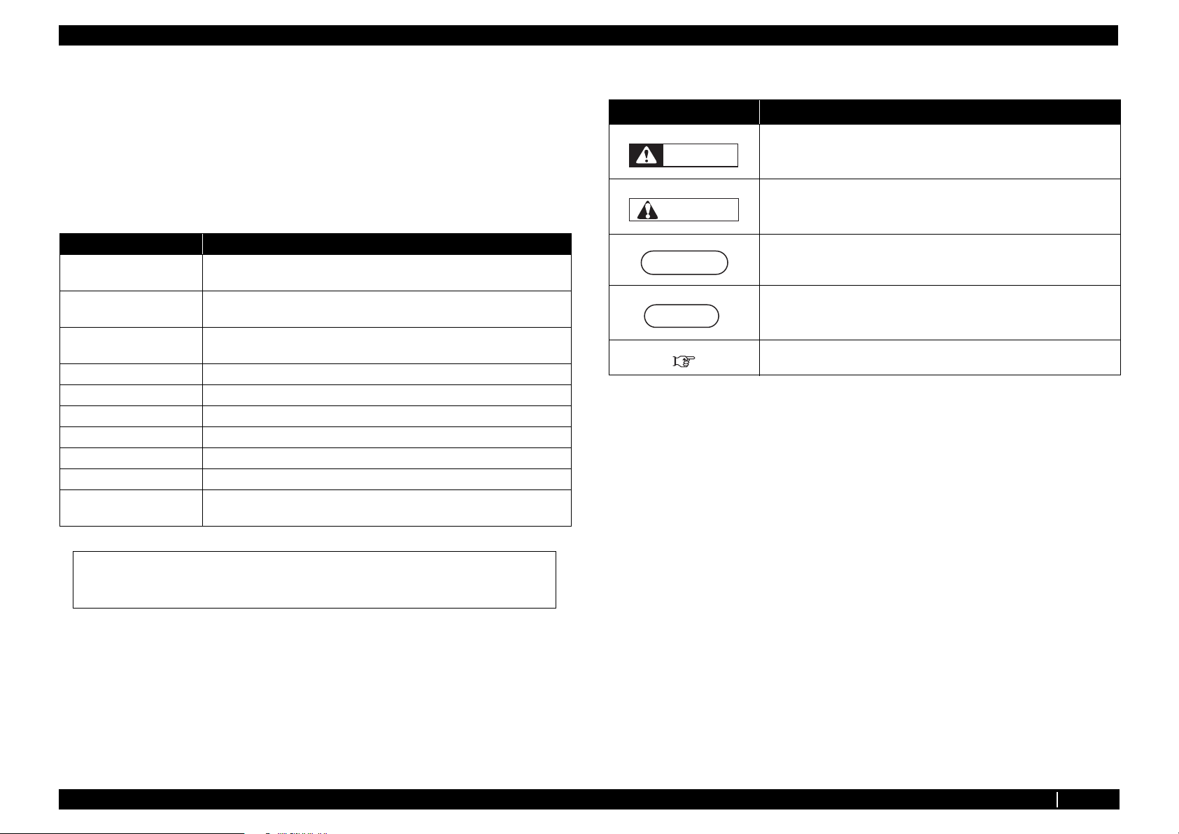
3. Manual Notation
The following symbols are used in this manual for easier understanding of the information.
Symbol Meaning
Must be followed carefully to avoid death or serious bodily injury
WARNING
Must be observed to avoid slight or moderate bodily injury or damage
CAUTION
NOTE
to your equipment
Contains important information and useful tips on the operation of the
product
Indicates useful tips for operating or understanding the equipment
TIP
Indicates reference pages in this manual
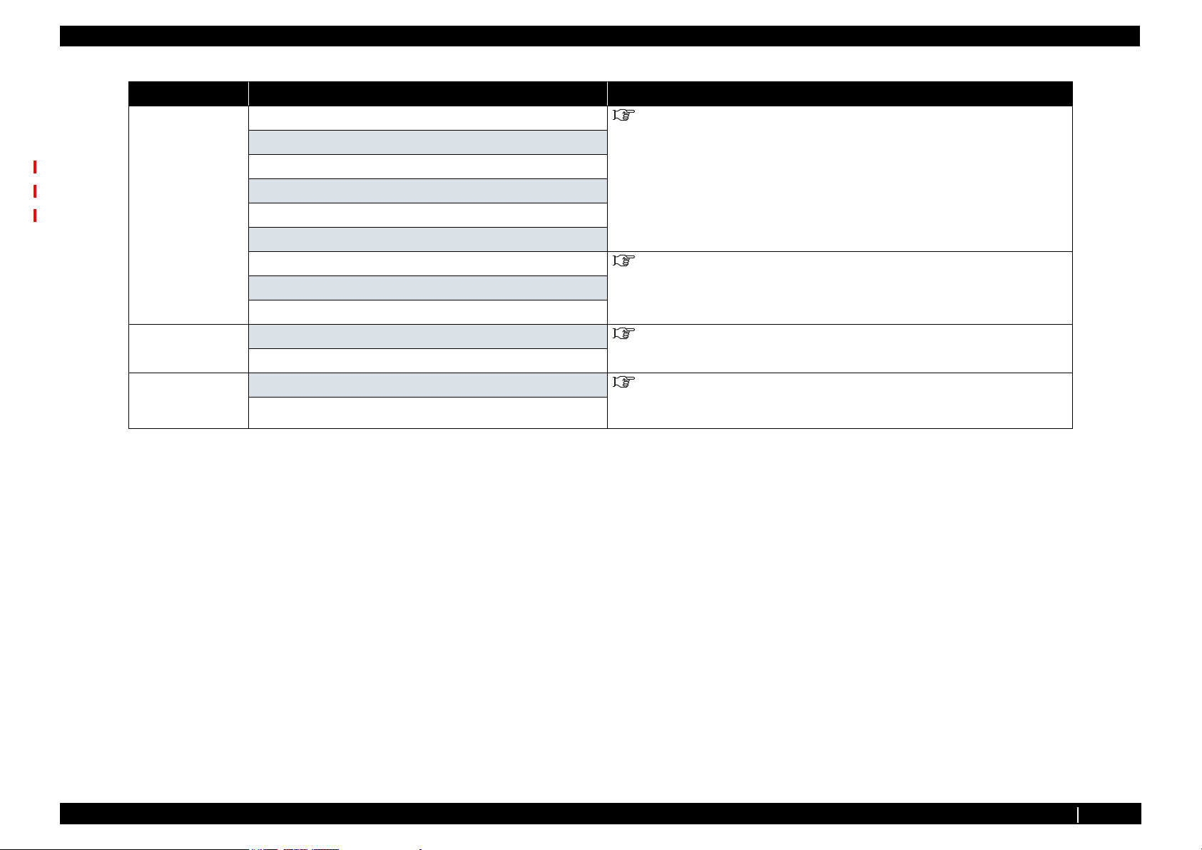
4. Establishment Date of This Document
This document was established on Mar. 31, 2011.
5. Firmware version covered by this document
Firmware version: V.1.00
Use the built-in self-diagnostic program to locate a defective part and adjust/check during
maintenance.
P.2
Page 9
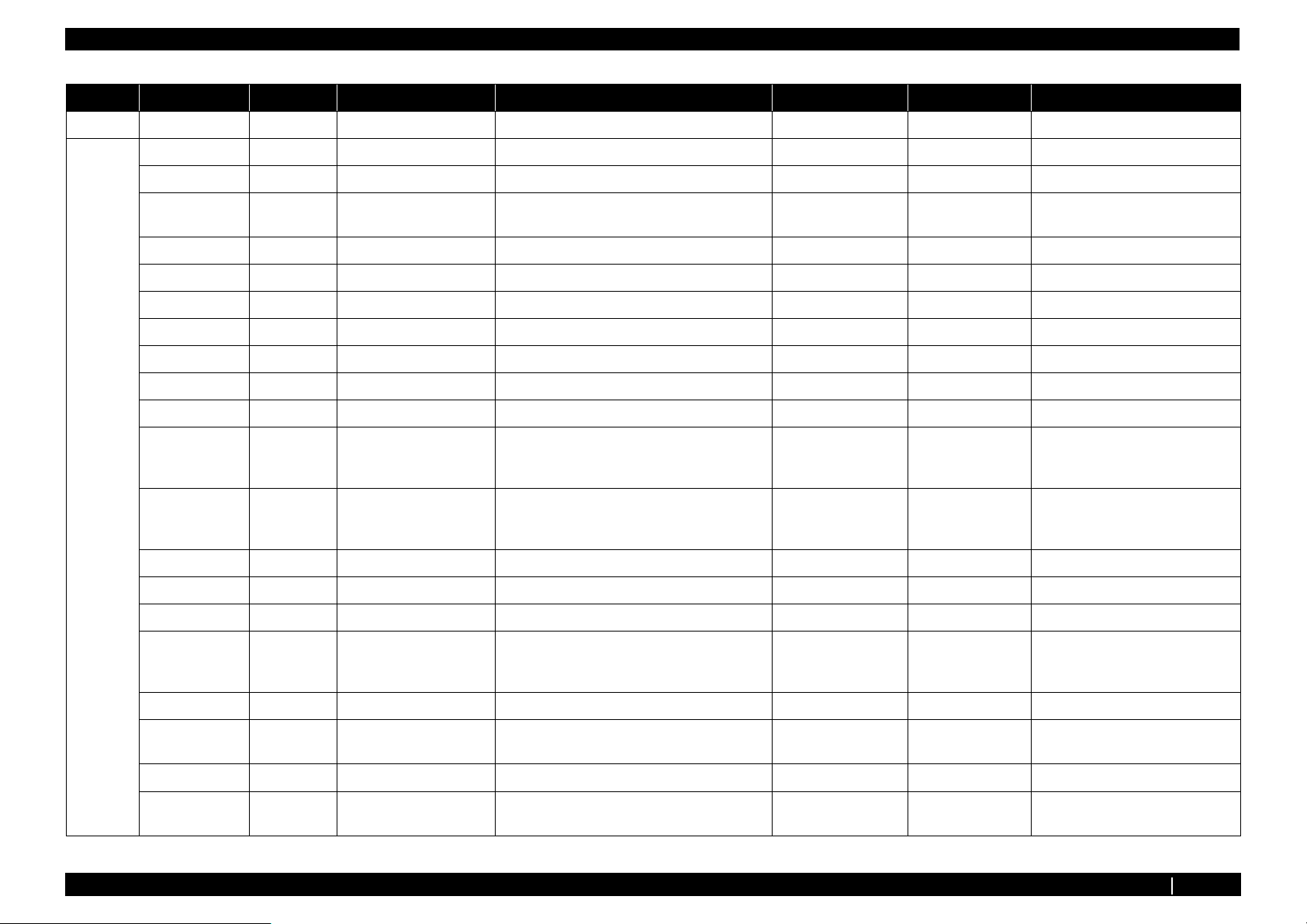
Revision History VJ1324E-M-02
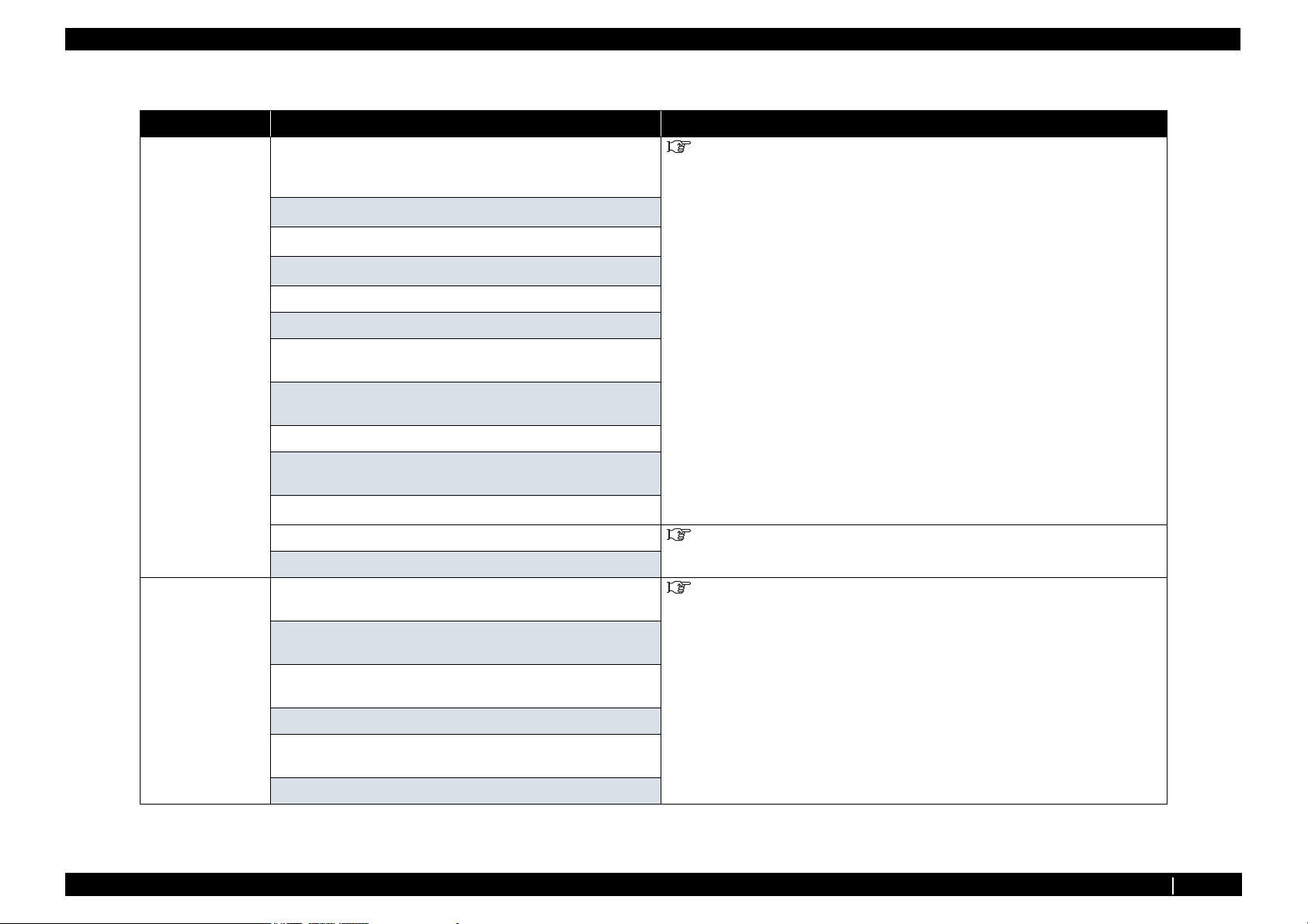
Revison Reason Chapter Section Contents Page No. Errata Remarks
00 - - - new - - -
01 Revising ALL ALL footer and header ALL - -
misdescription 2 2.2.3 Remove E080 P2-29 - -
undocumented 2 2.2.3 Add
E093,E146,E147,E140,E141,E142,E146,E147
misdescription 3 3.3.2 Add directions to CAUTION. P3-22 - -
misdescription 3 3.3.2 Add illustration. P3-24 - -
misdescription 3 3.4.12 Add TIP. P3-53 - -
misdescription 3 3.4.14 Add TIP. P3-56 - -
misdescription 3 3.5.2 Add TIP. P3-64 - -
misdescription 3 3.5.5 Add TIP. P3-67 - -
misdescription 3 3.5.6 Modify the procedure in Replacing HEATER. P3-71~85 - -
Working
efficiency
improvement
Working
efficiency
improvement
misdescription 3 3.7.8 Modify the length in the Table. P3-116 - -
undocumented 3 3.7.9 Add the procedure of Replacing Y Fitting P3-123 - -
misdescription 3 3.8.3 Modify the directions in TIP. P3-142 - -
Working
efficiency
improvement
3 3.6.8 Modify the illustration in Step 12. P3-96 - -
3 3.7.5 Modify the procedure in Replacing Carriage
Assy..
33.8.5
Wiper Assy → Wiper
P2-29~31 - -
P3-102~105 - -
P3-144 - -
misdescription 3 3.11.1 Add NOTE. P3-152 - -
changing
specifications
misdescription 3 3.11.3 Modify the directions in CAUTION. P3-157 - -
changing
specifications
3 3.11.2 Modify the directions in CAUTION. P3-153 - -
4 4.12 Add Rear/Edge Sensor Adjustment. P4-21~22 - -
Revision History P.3
Page 10
Revision History VJ1324E-M-02
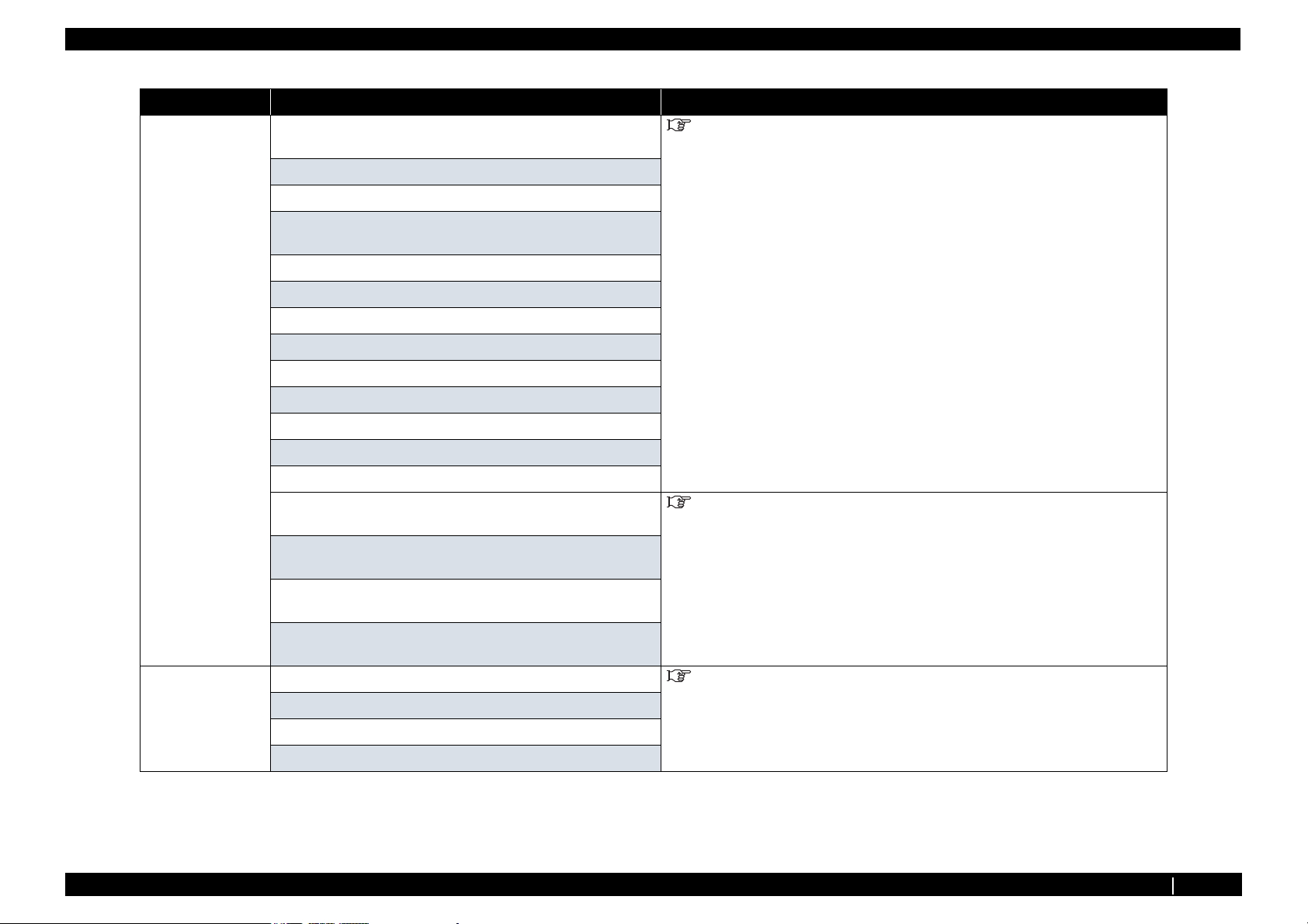
Revison Reason Chapter Section Contents Page No. Errata Remarks
01 misdescription 5 5.2.1 Modify the descriptions in NOTE. P5-3 - -
changing
specifications
misdescription 5 5.13 Modify the TIP. P5-73~78 - -
misdescription 7 7.4.1 Modify the Remarks in the 11 of Table 7-3. P7-6 - -
changing
specifications
5 5.3.2 Add S/C Log to Test Print Menu. P5-5 - -
5 5.3.2 Add Cut Function to Media Feed Menu. P5.5 - -
5 5.5.9 Add Initiallizing S/C Log to Record Menu. P5-18 - -
5 5.5.10 Modify the descriptions in NOTE. P5-24 - -
5 5.7 Add Bi-D Copy to Adjustment Menu. P5-28 - -
5 5.8.5 Modify the printing speed in Uni-D/Bi-D
Adjustment Menu.
5 5.8.8 Add S/C Log info to Test Printing Menu. P5-51 - -
5 5.8.8 Modify the Sample printings in TIP. P5-52 - -
5 5.10 Add S/C Log info to Sample printing Menu. P5-58 - -
5 5.11.2 Modify the Items and contents. P5-63 - -
5 5.12 Modify the items in Servo Settine Menu. P5-69 - -
5 5.13 Add Choke Valve endurance Menu. P5-70 - -
5 5.13.1 Modify Carriage speed. P5-71 - -
7 7.4.1 Add Solenoid Head Washing Kit to the Tools for
Adjustment.
P5-42~49 - -
P7-6 - -
misdescription 8 8.2.3 Modify the color of Status Lamp in the 9 of table
misdescription 8 8.3.2 Modify illustration in (2).. P8-8 - -
changing
specifications
misdescription 10 10.2 Modify the contents of Platen Heater (100) P10-7 - -
02 Revising ALL Header,Footer
Revising 4 4.2,4.3 VJ1324-M-02 or later to VJ1324-M-03 or later P4-2,P4-4 - -
Omitted 5 5.5 Add “S/C LogInit” to the contents in “Record” P5-7 - -
Omitted 5 5.5.9 Add “S/C LogInit” P5-18 - -
8 8.3.3 Add length changing function. - -
(2).
VJ1324-M-02 → VJ1324-M-03
P8-6 - -
-- -
Revision History P.4
Page 11
Revision History VJ1324E-M-02
Revison Reason Chapter Section Contents Page No. Errata Remarks
02 changing
specifications
5 5.5.9 Add “(4-C) Effect” P5-21 - -
5 5.5.10 Modify Head wavwform P5-24 - -
5 5.7.6 Modify speed and waveform P5-42 - -
5 5.7.8 Modify adjusting range of margin values. P5-50 - -
5 5.10.2 Modify (4) speed P5-64 - -
5 5.10.2 Modify (5) Setting range of mechanical
parameters
P5-66 - -
Revision History P.5
Page 12

VJ1324E-M-02
1 Safety Instruction
1.1 Introduction .................................................................. 1- 2
1.1.1 Types and Meanings of Warnings....................... 1-2
1.2 Warning Labels............................................................. 1- 2
1.2.1 Handling the Warning Labels .............................. 1-2
1.2.2 Location and Type of Warning Labels................. 1-2
P.1-1
Page 13
1.1 Introduction VJ1324E-M-02
1.1 Introduction
This chapter explains the installation of this printer, the warning terms that operators need to know, the
caution items and warning labels on the main unit.
WARNING
Make sure to follow all instructions and warnings on this manual when installing,
operating, or maintaining the equipment.
1.1.1 Types and Meanings of Warnings
Safety terms in this manual and the contents of warning labels attached to the printer
are categorized into the following five types depending on the degree of risk (or the
scale of the accident).
Make sure to understand the meaning of the following warning terms, and follow
the instruction in this manual
Safety terms Details
WARNING
CAUTION
Must be followed carefully to avoid death or serious bodily injury.
Must be observed to avoid slight or moderate bodily injury or damage to
the whole or each part of the product.
NOTE
• Make sure that all warning labels can be recognized.If the text or illustrations cannot be
seen clearly, clean or replace the label.
• When cleaning warning labels, use a cloth with water or neutral detergent. Do not use a
solvent or gasoline.
• If a warning label is damaged, lost, or cannot be recognized, replace the label.
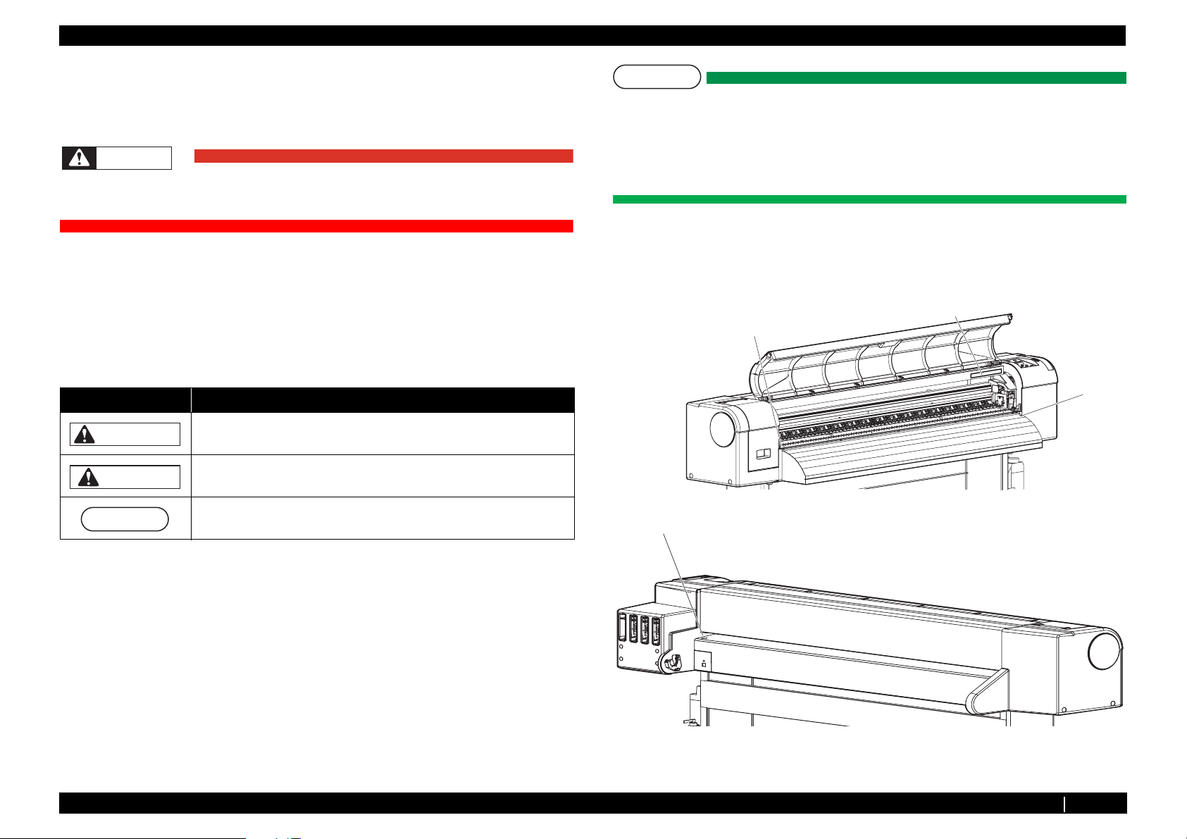
1.2.2 Location and Type of Warning Labels
The locations of warning labels are shown in the following figure.
1
2
2
NOTE
Contains important information and useful tips on the operation of the
product.
2
1.2 Warning Labels
This section explains the handling of warning label, pasting location and types.
Warning labels are attached to parts of the printer that need special caution.
Understand the locations and the descriptions of the danger associated with each
label before operating the printer.
1.2.1 Handling the Warning Labels
Make sure to note the following when handling the warning labels.
1.1.1 Types and Meanings of Warnings P.1-2
Page 14
1.2 Warning Labels VJ1324E-M-02
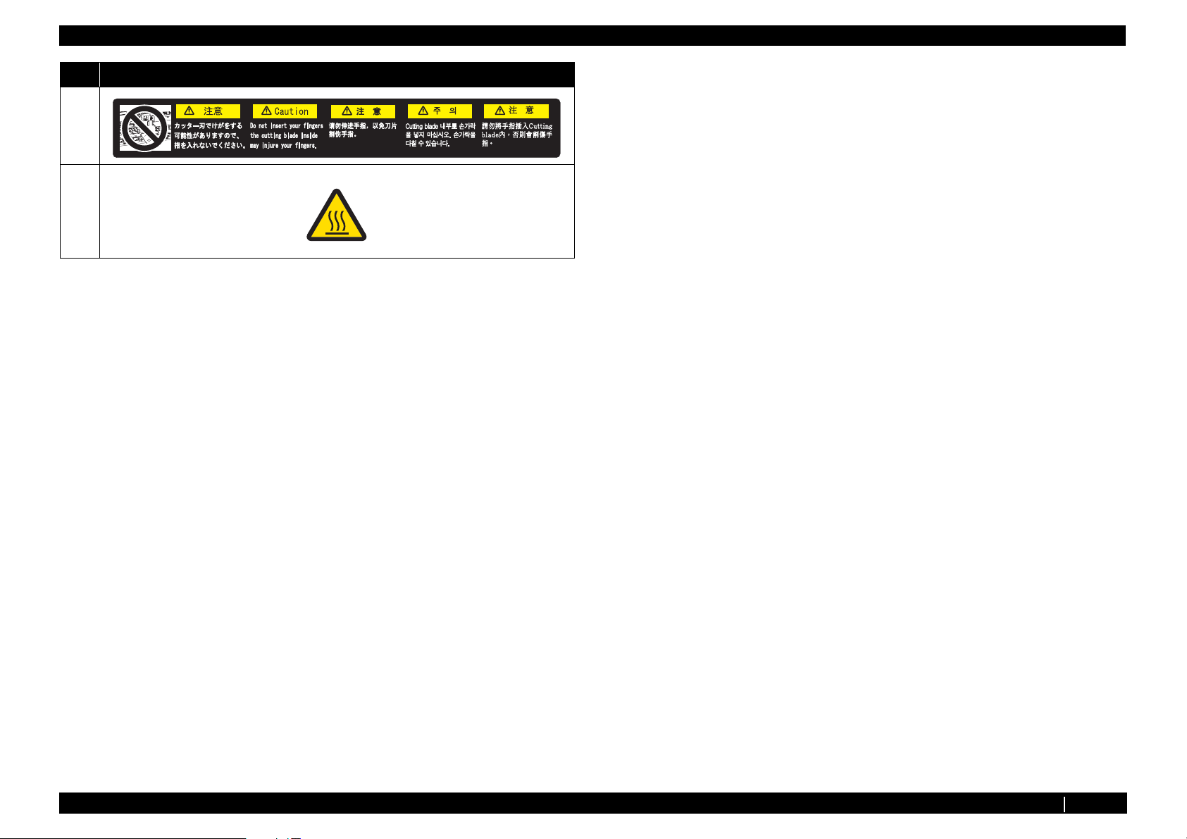
No. Types of Warning Labels
1
2
1.2.2 Location and Type of Warning Labels P.1-3
Page 15

VJ1324E-M-02
2 Trouble Shooting
2.1 Introduction .................................................................. 2- 2
2.2 Troubleshooting with Error Messages....................... 2- 7
2.2.1 Operation Status ................................................. 2-7
2.2.2 Errors with Message ........................................... 2-9
2.2.3 Errors Requiring Reboot ................................... 2-15
2.2.4 Error Messages During File Transmission ........ 2-32
2.3 Troubleshooting Without Error Messages............... 2- 35
2.3.1 Initial Operation Problems................................. 2-35
2.3.2 Media Feed Problems ....................................... 2-41
2.3.3 Printing Problems.............................................. 2-44
2.3.4 Noise Problems................................................. 2-57
2.3.5 Media Cutting Problems ........................................ 2-60
2.3.6 Online Function Problems................................. 2-63
2.3.7 Other Problems ................................................. 2-65
2.3.8 Problems in Using MUTOH Service Assistance 2-67
P.2-1
Page 16
2.1 Introduction VJ1324E-M-02
2.1 Introduction
This chapter provides information on possible causes of machine errors/damage and recovery actions.
If the machine is malfunctioning and an error message is displayed on Operation panel, refer to"2.2 Troubleshooting with Error Messages" p.2-7. If the machine is malfunctioning but no error messages are
displayed, refer to"2.3 Troubleshooting Without Error Messages" p.2-35If cause of errors/damage and recovery actions are not found in this chapter, or the machine cannot restore to normal status, please
contact the distributor you purchased the product from or our customer support center.
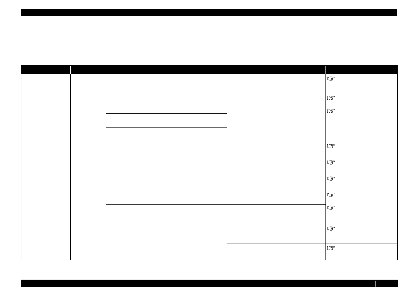
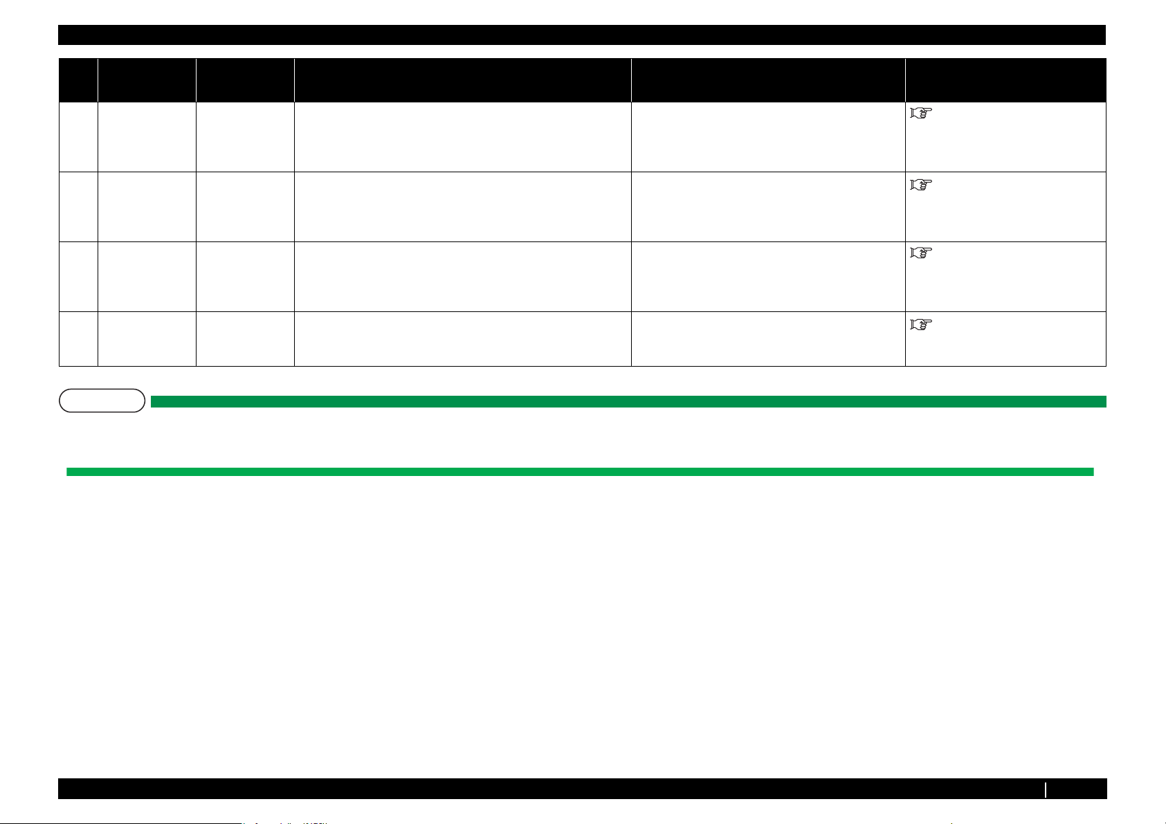
Table 2-1 Error type
No. Trouble Contents Reference
1
When the message is displayed Trouble with an error message displayed on Operation panel when the
printer is malfunctioning.
2
When the message is not displayed Trouble without an error message displayed on Operation panel even
when the printer is malfunctioning.
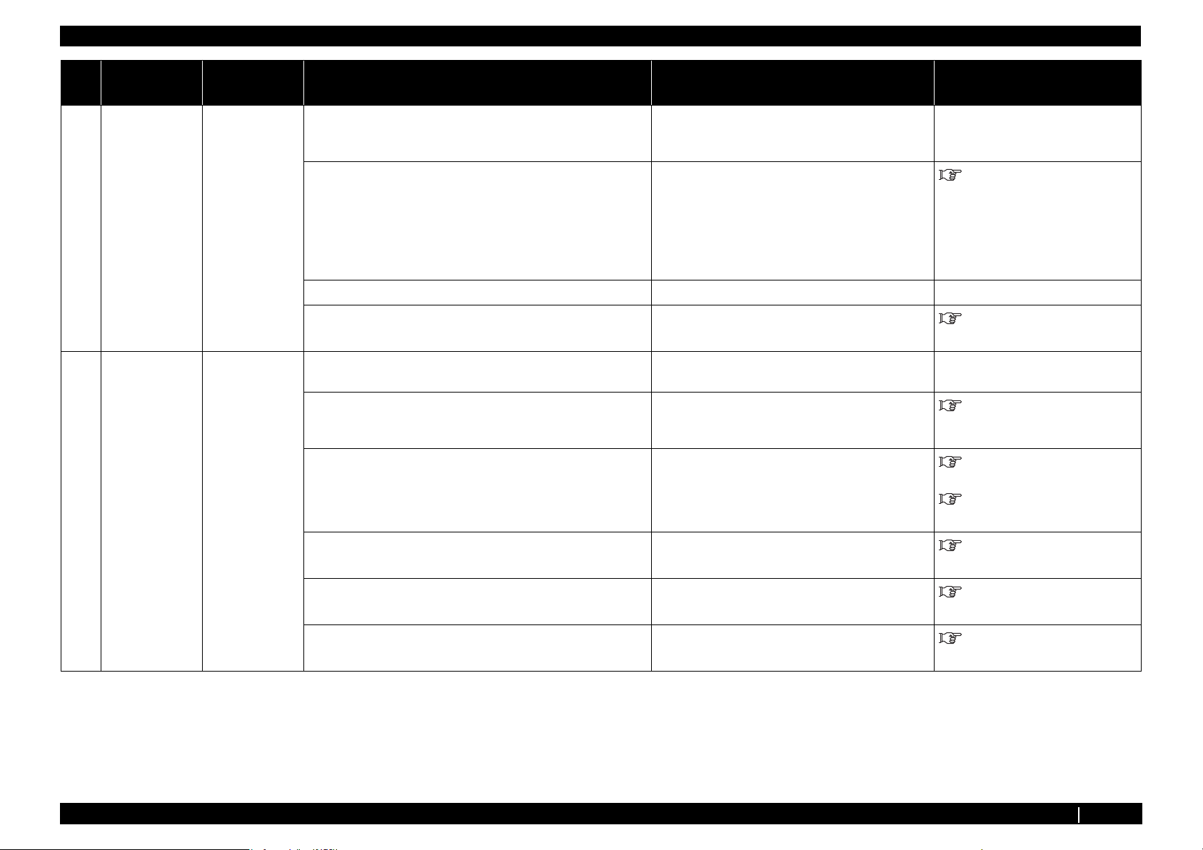
Table 2-2 When the message is displayed
Message type Contents Reference
Operation status Cover open "2.2.1 Operation Status" p.2-7
Mainte. Cover[*] Open (*L or R)
"2.2 Troubleshooting with Error
Messages" p.2-7
"2.3 Troubleshooting Without Error
Messages" p.2-35
Set media
End of Roll
No media
Error with message
Undefined Media "2.2.2 Errors with Message" p.2-9
Media Slant
Ink NearEnd
Ink End
NoCartridges
S/C Read Err
S/C Ink Err
S/C Code Err
P.2-2
Page 17
2.1 Introduction VJ1324E-M-02
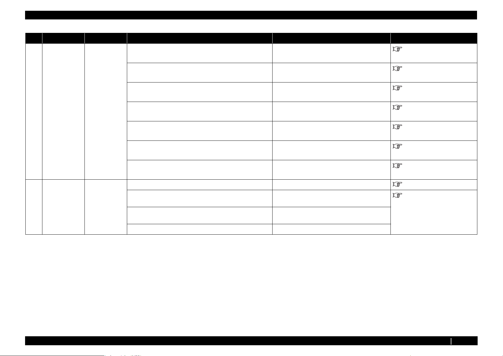
Table 2-2 When the message is displayed (Continued)
Message type Contents Reference
Error with message S/C Col. Err "2.2.2 Errors with Message" p.2-9
Full wasteInk Tank
Media cut Err
Smart/C End
Broken Chip
Check Life [Head ]
Check Life [Pump] "2.2.2 Errors with Message" p.2-9
Check Life [CR Motor]
Check Life [PF Motor]
Error requiring restart
Errors while
transmitting/
receiving data
E016 Error (CPU errors) [00] - [35] "2.2.3 Errors Requiring Reboot" p.2-15
E016 Errors (Mechanical errors) [065] - [152]
Transfer failed ******. "2.2.4 Error Messages During File Transmission" p.2-32
Boot transfer failed ******.
P.2-3
Page 18
2.1 Introduction VJ1324E-M-02
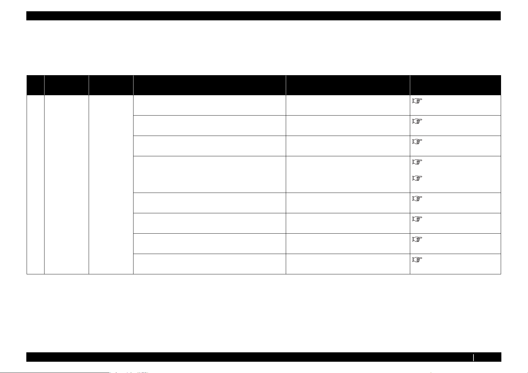
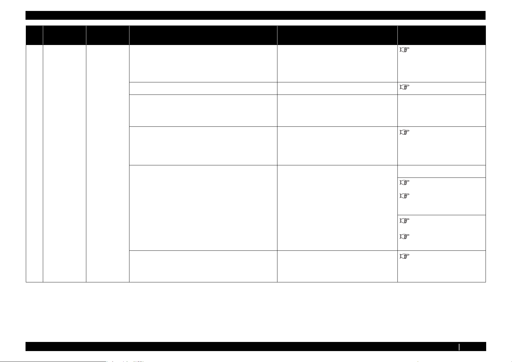
Table 2-3 When the message is not displayed
Message Symptoms Reference
Initial Operation
Problems
Media Feed Problems Media slips during media initialization or printing. "2.3.3 Printing Problems" p.2-44
Printer cannot be turned on "2.3.1 Initial Operation Problems" p.2-35
LCD display malfunction
Initial ink charge does not start
Initial ink charge started, but ink does not reach Head
Ink does not come out even after initial ink charge is completed
The printer does not operate after turned on.
The printer does not stop operation even when Front cover or
Maintenance cover is opened.
After the printer is turned on, "Initializing" is displayed and the
printer resets
Loading media does not start the initial operation
The printer does not operate even when Front cover or Maintenance
cover is closed.
The printer does not recognize the installed ink cartridges
Nothing can be input from Operation panel "2.3.1 Initial Operation Problems" p.2-35
Printing does not start even after receiving data.
Media skews or meanders during media initialization or printing.
Media wrinkles during media initialization or printing.
Media tears during media initialization or printing.
Media size is not correctly detected after media initialization.
LCD display malfunction
P.2-4
Page 19
2.1 Introduction VJ1324E-M-02
Table 2-3 When the message is not displayed (Continued)
Message Symptoms Reference
Printing Problems The printer does not print continuously. "2.3.3 Printing Problems" p.2-44
After printing, the printer feeds an extra amount of media.
Nozzles are clogged during printing
Cleaning does not mend the clogged nozzles or skewed ink
discharge.
Cannot print at all, a specific color is missing
The page is printed all black.
The page is printed blocky.
Images are printed unevenly.
Lines in the CR direction look split.
White or black lines appear on printed media
The printed borders are blurred.
There are unwanted dots (satellites).
Characters with jagged edges are printed.
Lines are printed blurry (messy printing result) "2.3.3 Printing Problems" p.2-44
Mixed color lines are not overlapped.
The printed results are uneven. (Vertical direction against the printer
unit)
The printed results are uneven. (Horizontal direction against the
printer unit)
Noise Problems Abnormal noise is heard when media is sucked "2.3.4 Noise Problems" p.2-57
Abnormal noise is heard during waiting time
Abnormal noise is heard while Head is moving laterally
Abnormal noise is heard when feeding media
P.2-5
Page 20
2.1 Introduction VJ1324E-M-02
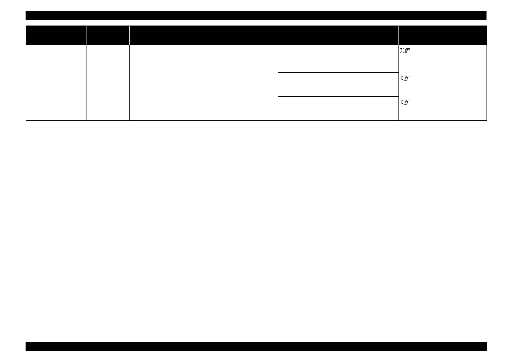
Table 2-3 When the message is not displayed (Continued)
Message Symptoms Reference
Online Function
Problems
Other Problems The printer hangs up "2.3.7 Other Problems" p.2-65
Problems in Using
MUTOH Service
Assistance
Other functions do not work correctly "2.3.6 Online Function Problems" p.2-63
Data or printing is garbled
Part of the data is not printed (missing)
The power is shut down during printing
Ink cartridges cannot be inserted
Ink spills out of Waste fluid tank
Ink spills out of Flushing box
Ink spills around X rail
MUTOH Service Assistance does not start up "2.3.8 Problems in Using MUTOH Service Assistance" p.2-67
"Transfer failed (Data timeout)" is displayed during transfer.
"Main F/W data is invalid" is displayed during firmware transfer.
"No compatibility between main F/W data and printer" is displayed
during firmware transfer.
"F/W version downgrade is not available" is displayed during
firmware transfer.
"2.3.8 Problems in Using MUTOH Service Assistance" p.2-67
"Heater controller F/W data is invalid" is displayed during Heater
controller firmware transfer.
"No compatibility between Heater controller F/W data and printer is
displayed during Heater controller firmware transfer.
P.2-6
Page 21
2.2 Troubleshooting with Error Messages VJ1324E-M-02
2.2 Troubleshooting with Error Messages
This section describes the messages displayed in normal operation and upon an error occurrence as well as how to correct the error. The available messages are as follows.
2.2.1 Operation Status
This section describes the message contents, check items, and recovery actions for normal operation.
No. Message Event/symptom Check item Action Reference
Table 2-4 Events and Check Items for Operation Status Messages
1 Cover open Front cover is
open.
2 Set media Media holding
lever is raised.
1. Is Cover sensor Assy wobbly? Tighten the screw on Cover sensor Assy .
2. Are the cables of F cover R sensor Assy and F cover L sensor
Assy securely connected?
3. Are F cover R sensor Assy and F cover L sensor Assy
damaged?
4. Check the operation of Cover sensor in “Sen 4: Lever” in the
self-diagnosis function.
5. MAIN board Assy may be damaged. Replace MAIN board Assy .
1. Does Pressurizing lever move smoothly? Lubricate
2. Is Lever sensor Assy securely installed? Adjust the mounting position of Lever sensor Assy .
3. Is the sensor portion of Lever sensor Assy dirty? Clean the sensor portion with a cotton swab, etc.
4. Is Lever sensor Assy securely installed? Securely connect Lever sensor cable Assy to
Securely connect the cable of F cover R sensor
Assy to MAIN board Assy connector (J13) and
the cable of F cover L sensor Assy to MAIN board
Assy connector (J14).
Replace F cover R sensor Assy and F cover L sensor
Assy .
pressure cam.
JUNCTION board Assy connector J15.
"3.3.3 Replacing Cover Switch
Assy、Sensor Cover L Assy, Sensor
Cover R Assy" p.3-25
"3.3.4 Replacing Cover L Cable
Assy" p.3-32
"3.3.5 Replacing Cover R Cable
Assy" p.3-35
"3.4.4 Replacing MAIN Board
Assy" p.3-42
"7.5 Lubrication/Bonding" p.7-
7
"3.6.7 Replacing T Fence, T
Fence Spring Assy" p.3-93
"3.6.5 Replacing Lever Sensor"
p.3-91
"3.6.6 Replacing Lever Sensor
Cable Assy" p.3-92
5. Check the operation of Lever sensor in “Sen 6: Lever” in the
self-diagnosis function.
6. MAIN board Assy may be damaged. Replace MAIN board Assy .
Replace Lever sensor Assy if it is not working
properly.
"3.6.5 Replacing Lever Sensor"
p.3-91
"3.4.4 Replacing MAIN Board
Assy" p.3-42
2.2.1 Operation Status P.2-7
Page 22
2.2 Troubleshooting with Error Messages VJ1324E-M-02
Table 2-4 Events and Check Items for Operation Status Messages(Continued)
No. Message Event/symptom Check item Action Reference
3 No media Displayed in the
following cases:
• When media
is not set
•When
printing
finishes in
cut media
mode
4
Maintenance
cover open
Maintenance
cover is open.
1. Is media edge sensor Assy cable at the head section
connected correctly?
2. Is media rear sensor Assy under media guide R connected
correctly?
3. Check sensor sensitivity from "Sen7: Edge AD" of selfdiagnosis function.
4. CR board Assy may be damaged. Replace CR board Assy .
5. Check presence of media from "Sen8: Rear AD" of selfdiagnosis function.
6. CR_FFC may be damaged. Replace CR_FFC.
7. MAIN board Assy may be damaged. Replace MAIN board Assy .
1. Is the maintenance cover open? Close maintenance cover. Operation Manual
2. Is maintenance cover sensor Assy loose? Tighten the screws of maintenance cover sensor Assy
3. Is the cable of maintenance cover sensor Assy securely
connected?
Securely connect it to CR board Assy connector.
Securely connect it to MAIN board Assy connector.
Replace P_Edge sensor Assy .
When "No media" is displayed even if media is set,
replace P_Rear sensor Assy .
.
Securely connect the cable of maintenance cover
sensor Assy to MAIN board Assy.
"3.7.4 Replacing CR Board
Assy" p.3-101
"3.4.4 Replacing MAIN Board
Assy" p.3-42
"3.7.16 Replacing P_EDGE
Sensor Assy" p.3-135
"3.7.4 Replacing CR Board
Assy" p.3-101
"3.10.2 Replacing P_REAR
Sensor" p.3-150
"3.11.3 Replacing CR_FFC"
p.3-154
"3.4.4 Replacing MAIN Board
Assy" p.3-42
"3.3.3 Replacing Cover Switch
Assy、Sensor Cover L Assy, Sensor
Cover R Assy" p.3-25
4. Is maintenance cover sensor Assy damaged? Replace maintenance cover sensor Assy .
2.2.1 Operation Status P.2-8
Page 23
2.2 Troubleshooting with Error Messages VJ1324E-M-02
2.2.2 Errors with Message
This section describes the contents of errors with messages as well as the check items and recovery actions.
These messages are displayed when an abnormal condition occurs while the machine is running.
Upon an occurrence of an error with message, the machine stops its operation at the same time.
The error can be cancelled by removing the error causes. After that, the machine will restart its operation.
No. Message Event/
symptom
1 Media detection
error
Media detection
failed
Check item Action Reference
1. Is media edge sensor Assy cable at head connected correctly? Securely connect it to CR board Assy connector.
2. Is media rear sensor Assy under media guide R connected
correctly?
3. Check sensor sensitivity from "Sen8:Edge AD" of selfdiagnosis function.
4. Is CR_FFC cable inserted obliquely? Securely connect to MAIN board Assy and CR board
5. CR_FFC may be damaged. Replace CR_FFC.
6. CR board Assy may be damaged. Replace CR board Assy .
7. Check presence of media from "Sen7:Rear AD" of selfdiagnosis function.
8. MAIN board Assy may be damaged. Replace MAIN board Assy .
Securely connect it to MAIN board Assy connector.
Replace P_Edge sensor Assy .
Assy
When "No media" is displayed even if media is set,
replace P_Rear sensor.
"3.7.4 Replacing CR Board
Assy" p.3-101
"3.4.4 Replacing MAIN Board
Assy" p.3-42
"3.7.16 Replacing P_EDGE
Sensor Assy" p.3-135
"3.4.4 Replacing MAIN Board
Assy" p.3-42
"3.7.4 Replacing CR Board
Assy" p.3-101
"3.11.3 Replacing CR_FFC"
p.3-154
"3.7.4 Replacing CR Board
Assy" p.3-101
"3.10.2 Replacing P_REAR
Sensor" p.3-150
"3.4.4 Replacing MAIN Board
Assy" p.3-42
2.2.2 Errors with Message P.2-9
Page 24
2.2 Troubleshooting with Error Messages VJ1324E-M-02
No. Message Event/
symptom
2
Media skew
error
3 Remove media Displayed if lever
Media is running
obliquely.
is raised during
printing or cutting
media and then
lowered without
removing media.
Check item Action Reference
1. Set media again and check reappearance. If this error is caused by user's inappropriate media
setting, instruct correct media setting procedure.
2. Is suction fan judged as normal when checked through "Test:
Fan" of self-diagnosis function?
Check the connection of following MAIN
・
board Assy connectors.
• Suction fan relay Assy : J27
• Replace cable of suction fan that does not
operate normally.
• Replace suction fan Assy .
3. Is shielding material secured at specified position? Remount it at specified position.
4. Check pressure lever operation. Apply grease (G501) to pressure cam and make
adjustment.
1. Does the same message appear if turning machine OFF and
turn it ON again?
2. Is pressure lever detected as normal when checked through
"Sen: Lever" of self-diagnosis function?
3. Check contact of lever sensor Assy . •
If the message appears, refer to the action in check
item No. 2.
Check that LCD monitor does not display up/down as
chattering when slowly raising/lowering pressure
lever.
Reconnect MAIN board Assy connector
J
15.
• If LCD displays as chattering, sensor may
be damaged. Replace lever sensor Assy .
―
"3.10.1 Replacing Adsorption
FAN" p.3-149
-
"7.5 Lubrication/Bonding" p.7-
7
―
"5.5.4 Sensor Menu" p.5-12
"3.4.11 Replacing JUNCTION
Board Assy" p.3-51
"3.6.5 Replacing Lever Sensor"
p.3-91
4. Is media rear sensor Assy under media guide R connected
correctly?
5. Check presence of media from "Sen: Rear AD" of self-
diagnosis function.
6. MAIN board Assy may be damaged. Replace MAIN board Assy .
Securely connect it to MAIN board Assy connector
J26.
When "No media" is displayed even if media is set,
replace P_Rear sensor Assy .
"3.4.4 Replacing MAIN Board
Assy" p.3-42
"3.10.2 Replacing P_REAR
Sensor" p.3-150
"3.4.4 Replacing MAIN Board
Assy" p.3-42
2.2.2 Errors with Message P.2-10
Page 25
2.2 Troubleshooting with Error Messages VJ1324E-M-02
No. Message Event/
symptom
Media cut error Even though
4
cutting operation
is performed,
media is not cut
off.
Check item Action Reference
1. Does media dust accumulate in cutter groove? Remove accumulated media dust along groove. Operation Manual
2. Is cutter cap securely installed? Reinstall cutter cap securely. Operation Manual
3. Check cutter sliding up/down operation.
4. When setting cutter, lower cutter with finger and check that
cutter rises to upper end only by spring force.
5. When setting cutter after removing cutter spring, does cutter
lower to lower end by its own weight?
6. Check if solenoid goes up/down from "Life: Cutter"
of self-diagnosis function.
a) Goes up/down:
Check the position where cutter goes down to cutter
groove.
b) Does not go up/down:
• When it does not rise:
Refer to action in check item No. 4.
• When it rises:
Refer to action in check item No. 5.
• When it lowers:
Cutter spring may be defective. Replace cutter
spring referring to exploded views.
• When it does not lower:
Cutter may be defective. Replace cutter.
-
• OK:
Cutter has reached the end of life or be damaged.
Replace cutter with new one.
• NG:
Adjust cutter holder position.
Connector may be poorly connected.
Check the connection of following connectors.
―
"3.7.15 Replacing Cutter
Solenoid Assy, Cutter Solenoid
Spring Assy" p.3-133
-
Operation Manual
"3.7.15 Replacing Cutter
Solenoid Assy, Cutter Solenoid
Spring Assy" p.3-133
"3.7.4 Replacing CR Board
Assy" p.3-101
"3.4.4 Replacing MAIN Board
Assy" p.3-42
7. CR_FFC may be broken, solenoid Assy may be
defective, or each board Assy may be defective.
If solenoid goes up/down, replace CR_FFC.
"3.11.3 Replacing CR_FFC"
p.3-154
a) Replace CR_FFC with new one.
2.2.2 Errors with Message P.2-11
Page 26
2.2 Troubleshooting with Error Messages VJ1324E-M-02
No. Message Event/
symptom
4
Media cut error Even though
cutting
operation is
performed,
media is not cut
off.
Check item Action Reference
b) Replace solenoid Assy with new one. (Check by
connecting connectors directly)
c) Replace CR board Assy .
d) Replace MAIN board Assy .
If solenoid goes up/down, replace solenoid Assy .
After replacement, adjust sensor reflection amount
from "Sen: Edge AD" of "Test: Sensor" of selfdiagnosis function.
Before replacing MAIN board, back up parameters
and recover to new MAIN board Assy . Then start
operation check.
"3.7.15 Replacing Cutter
Solenoid Assy, Cutter Solenoid
Spring Assy" p.3-133
"3.7.4 Replacing CR Board
Assy" p.3-101
"3.4.4 Replacing MAIN Board
Assy" p.3-42
2.2.2 Errors with Message P.2-12
Page 27

2.2 Troubleshooting with Error Messages VJ1324E-M-02
No. Message Event/
symptom
41.[KCMY]
Ink Near End
2. [KCMY]
Ink End
The ink color that
is/are subject to
this caution is/are
displayed in the [
].
5[KCMY]
No Cartridge
1. Ink is
running
short.
Printing is
possible.
2. Ink has run
out. Any
printing
operation
stops
immediately.
Cartridge is not
installed.
Check item Action Reference
1. Check which cartridge has no ink from "Sen: Ink NOT" of
self-diagnosis function.
2. Check contact of the ink sensor Assy . Reconnect following connectors.
3. For the ink color that is displayed as "Ink Near End" or "Ink
End", switch ink sensor Assy connector with that of normally
displayed ink color.
Remove all cartridges and lightly push the black resin
lever of ink sensor Assy (K, C, M, Y) to check that
the display of "Sen: Ink NOT" changes.
connector18(K)
•
connectorJ9(C)
•
• connectorJ10(M)
connectorJ11(Y)
•
• If ink color display changes after
replacing connector:
Ink sensor Assy is damaged. Replace ink
sensor Assy .
• If ink color display does not change after
replacing connector:
MAIN board Assy may be
damaged.Replace MAIN board Assy .
1. Turn machine OFF. Turn it ON again and check if the same
message appears.
If message appears: Refer to action in check item No.
2.
"5.5.4 Sensor Menu" p.5-12
"3.4.4 Replacing MAIN Board
Assy" p.3-42
"3.9.1 Replacing Cartridge
Holder Assy" p.3-146
"3.4.4 Replacing MAIN Board
Assy" p.3-42
―
2. Check presence of ink cartridge from "Sen: Ink NOT" of selfdiagnosis function.
3. Check contact of ink sensor Assy connector.
4. For the ink color that is displayed as "No cartridge", switch
ink sensor Assy connector with that of normally displayed
ink color.
Remove all cartridges and lightly push the switch of
ink NOT sensor Assy (K, C, M, Y) with something
with a flat tip such as ballpoint pen to check that the
display of "Sen: Ink NOT" changes.
Reconnect following connectors.
• connector 15(K)
• connector J6(C)
• connector J7(M)
• connector J8(Y)
If ink color displayed as "No cartridge" changes after
replacing connector:
Ink sensor Assy is damaged. Replace ink
"5.5.4 Sensor Menu" p.5-12
"3.4.4 Replacing MAIN Board
Assy" p.3-42
"3.9.1 Replacing Cartridge
Holder Assy" p.3-146
sensor Assy .
2.2.2 Errors with Message P.2-13
Page 28
2.2 Troubleshooting with Error Messages VJ1324E-M-02
No. Message Event/
Check item Action Reference
symptom
6Life Times
[Head]
7Life Times [PF
Motor]
8 Life Times [CR
Motor]
9Life Times
[Pump]
The operational
life of Print head
has almost
expired.
The operational
life of PF motor
has almost
expired.
The operational
life of CR motor
has almost
expired.
The operational
life of Pump has
almost expired.
Check the condition of Head. Replace Head as necessary. Clear the counter after
The operational life of PF motor has almost expired. Replace PF motor as necessary.
Check the condition of CR motor. Replace CR motor as necessary. Clear the counter
Check the condition of Pump. Replace Pump as necessary. Clear the counter after
NOTE
• The square bracket pair in an error message indicates the applicable ink color.
• If no ink and no cartridge occur at the same time, no cartridge message has priority to be displayed.
replacing it.
replacing it.
after replacing it.
replacing it.
Clear the counter after
"3.7.6 Replacing Print Head"
p.3-106
"3.5.1 Replace PF Motor Assy"
p.3-61
"3.6.1 Replacing CR Motor
Assy" p.3-86
"3.8.1 Replacing Maintenance
Assy" p.3-138
2.2.2 Errors with Message P.2-14
Page 29
2.2 Troubleshooting with Error Messages VJ1324E-M-02
2.2.3 Errors Requiring Reboot
This section describes the contents of reboot-requiring errors as well as the check items and recovery actions.
These errors are issued when any of the following critical problems occur.
• Obstacle that prevents the machine's operation
• Damage of electric circuits (Boards, Motors, Sensors)
• Abnormal operation of control programs
When any of the above conditions occur, the machine follows the steps shown below before stopping its operation.
1. Turn OFF the driving system power automatically.
2. Flash all lamps on Operation panel and generate intermittent audible alarm.
3. Display the applicable error message on the LCD.
The error can be cancelled by removing the error causes and restarting the machine.
(1) CPU system serious error
No. Message Event/
symptom
1 E 016Interrupt
[00]
2 E016 TLB Modif
[01]
Interruption
exception error:
An anomaly is
detected during
interruption
process.
Command border
exception/TLB
exception (load or
command fetch)
error:
An anomaly is
detected in
command border.
Or TLB exception
is detected while
loading data or
fetching data.
Check item Action Reference
1. Check AC power supply and printer peripherals.
2. Check whether the same error occurs. Even when there is no
problem, turn off the printer and turn it back on a few times to
check.
3. Check the serial number of the printer.
4. MAIN board Assy may be damaged.
• Replace MAIN board Assy . Operation Manual
"3.4.4 Replacing MAIN Board
Assy" p.3-42
2.2.3 Errors Requiring Reboot P.2-15
Page 30

2.2 Troubleshooting with Error Messages VJ1324E-M-02
No. Message Event/
symptom
3 E 016 TLB-L/1
[02]
4 E 016 TLB-S
[03]
5 E 016 AddErr-L/l
[04]
Data border
exception/TLB
exception (store)
error:
An anomaly is
detected in data
border.
Or TLB exception
is detected while
storing data.
Data border
exception/TLB
exception (store)
error:
An anomaly is
detected in data
border.
Or TLB exception
is detected while
storing data.
Address
exception error
(load or command
fetch):
Address error is
detected while
loading or
fetching
command.
Check item Action Reference
1. Check AC power supply and printer peripherals.
2. Check whether the same error occurs. Even when there is no
problem, turn off the printer and turn it back on a few times to
check.
3. Check the serial number of the printer.
4. MAIN board Assy may be damaged.
• Replace MAIN board Assy . Operation Manual
"3.4.4 Replacing MAIN Board
Assy" p.3-42
6 E 016 AddErr-S
[05]
Address
exception error
(store):
An address error
is detected while
escaping.
2.2.3 Errors Requiring Reboot P.2-16
Page 31

2.2 Troubleshooting with Error Messages VJ1324E-M-02
No. Message Event/
symptom
7 E 016 BUS Err-L
[06]
8 E 016 BusErr-L/S
[07]
9 E 016SystemCall
[08]
Pass exception
error (command
fetch):
Address error is
detected while
loading or storing
command.
Bus exception
error (load or
store):
Bus error is
detected while
loading or storing
command.
System call
exception error:
An anomaly is
detected in
system call.
Check item Action Reference
1. Check the serial number of the printer.
2. MAIN board Assy may be damaged.
1. Check AC power supply and printer peripherals.
2. Check whether the same error occurs. Even when there is no
problem, turn off the printer and turn it back on a few times to
check.
3. Check the serial number of the printer.
4. MAIN board Assy may be damaged.
• Replace MAIN board Assy . "3.4.4 Replacing MAIN Board
Assy" p.3-42
10 E016 BreakPoint
[09]
11 E 016 Reserved
[10]
12 E 016 Copro
[11]
Break point
exception error:
An anomaly is
detected in break
point.
Reserved
command
exception error:
An anomaly is
detected in
reserved
command.
Coprocessor
disabled
exception error:
An anomaly is
detected in
coprocessor .
2.2.3 Errors Requiring Reboot P.2-17
Page 32

2.2 Troubleshooting with Error Messages VJ1324E-M-02
No. Message Event/
symptom
13 E 016 Overflow
[12]
14 E 016 Trap
[13]
15 E 016 Floating
[15]
16 E 016 WatchDog
[32]
Arithmetic
overflow
exception error:
Overflow is
detected.
Arithmetic
overflow
exception error:
Overflow is
detected.
Floating decimal
point exception
error:
An anomaly is
detected in
floating decimal
point.
Watchdog timeout exception
error:
A time-out is
detected in
Watchdog.
Check item Action Reference
1. Check AC power supply and printer peripherals.
2. Check whether the same error occurs. Even when there is no
problem, turn off the printer and turn it back on a few times to
check.
3. Check the serial number of the printer.
4. MAIN board Assy may be damaged.
• Contact your local MUTOH dealer.
• Replace MAIN board Assy .
"3.4.4 Replacing MAIN Board
Assy" p.3-42
17 E 016 Abort Err
[33]
18 E016 Flash
Rom[35]
19 E016 Exception
Err [XX]
Abort error:
Abort is detected.
The content of
flash ROM may
be destroyed.
EXC error
(undefined) other
than the above has
occured.
XX stands for a
number.
2.2.3 Errors Requiring Reboot P.2-18
Page 33

2.2 Troubleshooting with Error Messages VJ1324E-M-02
T I P
For the PC settings, refer to your PC's operation manual.
2.2.3 Errors Requiring Reboot P.2-19
Page 34

2.2 Troubleshooting with Error Messages VJ1324E-M-02
(2) Mechanical Serious Errors
No. Message Symptoms Check Item Action Reference
1 E 065Err
PF motor
Abnormal
condition in PF
motor (X-axis)
during printer
operation.
Displayed if
the difference
between motor
command
value and
feedback from
encoder is
large.
1. Check error history from "Test: Record" of self-
-
diagnosis function.
2. Set the number of endurance running cycles to 50 or
more from "Life: PF motor" of self-diagnosis
function, and check if "PF motor error" occurs.
3. Check "Encoder: PF" from "Test: Encoder" of selfdiagnosis function.
Check the connection of the following MAIN
board Assy connectors:
• PF motor cable Assy connector
• PF encoder Assy connector
If NG, check the connection of MAIN board
Assy connector.
4. Is the area around PF encoder contaminated? Clean around PF encoder.
Replace PF encoder if it is damaged.
5. Check if MAIN Power Board normally supplies
DC24V.
Replace the power board Assy if it is
damaged.
6. PF motor Assy may be damaged. Replace PF motor Assy .
7. MAIN board Assy may be defective. Replace MAIN board Assy .
"5.5.9 Record Menu" p.5-18
"5.12 Endurance Running
Menu" p.5-71
"3.4.4 Replacing MAIN Board
Assy" p.3-42
"3.4.4 Replacing MAIN Board
Assy" p.3-42
"3.5.3 Replacing PF Encoder
Assy" p.3-65
"3.4.10 Replacing Power Board
Assy" p.3-50
"3.5.1 Replace PF Motor Assy"
p.3-61
"3.4.4 Replacing MAIN Board
Assy" p.3-42
2.2.3 Errors Requiring Reboot P.2-20
Page 35

2.2 Troubleshooting with Error Messages VJ1324E-M-02
No. Message Symptoms Check Item Action Reference
2 E 067Err
PF encoder
Abnormal
condition in
media feed
amount (Xaxis) during
printer
operation.
Displayed if
there is no
feedback from
encoder.
1. Check error history from "Test7: Record" of self-
-
diagnosis function.
1.
2. Set the number of endurance running cycles to 50 or
more from "Life: PF motor" of self-diagnosis
function, and check if "PF encoder error" occurs.
3. Check "Encoder: PF" from "Test5: Encoder" of selfdiagnosis function.
Check the connection of the following MAIN
board Assy connectors:
• PF motor cable Assy connector
• PF encoder Assy connector
If NG, check the connection of MAIN board
Assy connector.
4. Is the area around PF encoder contaminated? Clean around PF encoder.
Replace PF encoder if it is damaged.
5. Check if MAIN Power Board normally supplies
DC24V.
Replace the power board Assy if it is
damaged.
6. PF motor Assy may be damaged. Replace PF motor Assy .
7. MAIN board Assy may be defective. Replace MAIN board Assy .
"5.5.9 Record Menu" p.5-18
"5.12 Endurance Running
Menu" p.5-71
"3.4.4 Replacing MAIN Board
Assy" p.3-42
"5.5.4 Sensor Menu" p.5-12
"3.4.4 Replacing MAIN Board
Assy" p.3-42
"3.5.3 Replacing PF Encoder
Assy" p.3-65
"3.4.10 Replacing Power Board
Assy" p.3-50
"3.5.1 Replace PF Motor Assy"
p.3-61
"3.4.4 Replacing MAIN Board
Assy" p.3-42
2.2.3 Errors Requiring Reboot P.2-21
Page 36

2.2 Troubleshooting with Error Messages VJ1324E-M-02
No. Message Symptoms Check Item Action Reference
3
E069 Err
PF Timeout
An anomaly is
detected in media
feed amount (Xaxis) during
printer operation.
Displayed when
Grid roller has not
reached the
designated
position.
1. Check error history from "Test7: Record" of self-
- "5.5.9 Record Menu" p.5-18
diagnosis function.
2. Set the number of endurance running cycles to 50 or
more from "Life2: PF motor" of self-diagnosis
function, and check if "PF motor Timeout" occurs.
Check the connection of following MAIN
board Assy connectors.
• PF motor cable Assy connector
• PF encoder Assy connector
Replace the power board Assy if it is
damaged.
3. Check "Encoder: PF" from "Test5: Encoder" of selfdiagnosis function.
4. Check if MAIN Power Board normally supplies
DC24V.
If NG, check the connection of MAIN board
Assy connector.
Replace the power board Assy if it is
damaged.
5. PF motor Assy may be defective. Replace PF motor Assy .
6. MAIN board Assy may be defective. Replace MAIN board Assy .
"3.4.4 Replacing MAIN Board
Assy" p.3-42
"5.12 Endurance Running
Menu" p.5-71
"5.5.4 Sensor Menu" p.5-12
"3.4.10 Replacing Power Board
Assy" p.3-50
"3.4.4 Replacing MAIN Board
Assy" p.3-42
"3.4.10 Replacing Power Board
Assy" p.3-50
"3.5.1 Replace PF Motor Assy"
p.3-61
"3.4.4 Replacing MAIN Board
Assy" p.3-42
2.2.3 Errors Requiring Reboot P.2-22
Page 37

2.2 Troubleshooting with Error Messages VJ1324E-M-02
No. Message Symptoms Check Item Action Reference
4
E071 Err
PF Current
E073 Err
PF2 Current
An overload
condition is
detected in PF
motor (X-axis)
during printer
operation.
Check error history from "Test7: Record" of self-
1.
-
diagnosis function.
2. Set the number of endurance running cycles to 50 or
more from "Life2: PF motor" of self-diagnosis
function, and check if "PF motor Timeout" occurs.
Check the connection of following MAIN
board Assy connectors.
• PF motor cable Assy connector
• PF encoder Assy connector
Replace the power board Assy if it is
damaged.
Check "Encoder: PF" from "Test5: Encoder" of self-
3.
diagnosis function.
4. Check if MAIN Power Board normally supplies
DC24V.
If NG, check the connection of MAIN board
Assy connector.
Replace the power board Assy if it is
damaged.
5. PF motor Assy may be defective. Replace PF motor Assy .
6. MAIN board Assy may be defective. Replace MAIN board Assy .
"5.5.9 Record Menu" p.5-18
"5.12 Endurance Running
Menu" p.5-71
"5.5.4 Sensor Menu" p.5-12
"3.4.4 Replacing MAIN Board
Assy" p.3-42
"3.4.10 Replacing Power Board
Assy" p.3-50
"3.5.1 Replace PF Motor Assy"
p.3-61
"3.4.4 Replacing MAIN Board
Assy" p.3-42
2.2.3 Errors Requiring Reboot P.2-23
Page 38

2.2 Troubleshooting with Error Messages VJ1324E-M-02
No. Message Symptoms Check Item Action Reference
5 E066 Err
CR Motor
An anomaly is
detected in CR
motor (Y-axis)
during printer
operation.
1. Check error history from "Test7: Record" of self-
diagnosis function.
2. Move carriage in both directions while the printer is
turned off, and check if there is any position where
carriage does not move smoothly.
Set the number of endurance running cycles to 50 or
3.
more from "Life1: CR motor" of self-diagnosis
function, and check if "CR motor error" occurs.
4. Check if T fence is contaminated or worn out.
-
Clean and lubricate CR rail roller guide.
• Check the connection of following
connectors.
MAIN board:
• CR motor relay Assy
• CR_FFC
CR board:
• CR_FFC
• If grease or dust collect: Wipe fence with
a dry cloth.
• If ink deposit presents: Wipe it off with
cloth dampened with neutral detergent.
• If contamination or deposit is too heavy:
Replace T fence.
"5.5.9 Record Menu" p.5-18
"7.5 Lubrication/Bonding" p.7-
7
"3.4.4 Replacing MAIN Board
Assy" p.3-42
"5.5.9 Record Menu" p.5-18
"3.7.4 Replacing CR Board
Assy" p.3-101
"3.6.7 Replacing T Fence, T
Fence Spring Assy" p.3-93
5. Check "Encoder: CR" from "Check: Test” -"Test5:
Encoder" of self-diagnosis function.
If NG:
a) Check the following cable connection:
"3.7.4 Replacing CR Board
Assy" p.3-101
• CR board Assy .
b) Replace the following parts:
•T fence
"3.11.3 Replacing CR_FFC"
p.3-154
• CR motor Assy
• CR board Assy
• CR_FFC
2.2.3 Errors Requiring Reboot P.2-24
Page 39

2.2 Troubleshooting with Error Messages VJ1324E-M-02
No. Message Symptoms Check Item Action Reference
6 E068 Err CR
Encoder
Displayed when
there is a big
difference
between motor
command value
and feedback
from encoder.
1. Check error history from "Test7: Record" of self-
-
diagnosis function.
2. Move carriage in both directions while the printer is
Clean and lubricate CR rail roller guide.
turned off, and check if there is any position where
carriage does not move smoothly.
3. Set the number of endurance running cycles to 50 or
more from "Life 1: CR motor" of self-diagnosis
function, and check if "Y encoder error" occurs.
• Check the connection of following
connectors.
MAIN board:
• CR motor relay Assy
• CR_FFC
CR board:
• CR_FFC connector
4. Check if T fence is contaminated or worn out. • If grease or dust collect: Wipe fence with
a dry cloth.
• If ink deposit presents: Wipe it off with
cloth dampened with neutral detergent.
• If contamination or deposit is too heavy:
Replace T fence.
5. Check "Encoder: CR" from "Check: Test” -"Test5:
Encoder" of self-diagnosis function.
If NG:
a) Check the following cable connection:
• CR board Assy connector.
b) Replace the following parts:
•T fence
• CR motor Assy
• CR board Assy
• CR_FFC
-
-
"3.4.4 Replacing MAIN Board
Assy" p.3-42
"5.12 Endurance Running
Menu" p.5-71
"3.7.4 Replacing CR Board
Assy" p.3-101
"3.6.7 Replacing T Fence, T
Fence Spring Assy" p.3-93
"3.7.4 Replacing CR Board
Assy" p.3-101
"3.11.3 Replacing CR_FFC"
p.3-154
2.2.3 Errors Requiring Reboot P.2-25
Page 40

2.2 Troubleshooting with Error Messages VJ1324E-M-02
No. Message Symptoms Check Item Action Reference
7 E070 Err CR
Timeout
A timeout is
detected in the
Head shift
amount (Y-axis)
during printer
operation.
Displayed when
Carriage has not
reached the
designated
position.
1. Check error history from "Test: Record" of self-
-
diagnosis function.
2. Move carriage in both directions while the printer is
Clean and lubricate CR rail roller guide.
turned off, and check if there is any position where
carriage does not move smoothly.
3. Set the number of endurance running cycles to 50 or
more from "Life1 : CR motor" of self-diagnosis
function, and check if "CR time out" occurs.
• Check the connection of following
connectors.
MAIN board:
• CR motor relay Assy
• CR_FFC
CR board:
• CR_FFC connector
4. Check if T fence is contaminated or worn out. • If grease or dust collect: Wipe fence with
a dry cloth.
• If ink deposit presents: Wipe it off with
cloth dampened with neutral detergent.
• If contamination or deposit is too heavy:
Replace T fence.
5. Check "Encoder: CR" from "Check: Test” -"Test5:
Encoder" of self-diagnosis function.
If NG:
a) Check the following cable connection:
• CR board Assy connector.
b) Replace the following parts:
•T fence
• CR motor Assy
• CR board Assy
• CR_FFC
"5.5.9 Record Menu" p.5-18
"7.5 Lubrication/Bonding" p.7-
7
"3.4.4 Replacing MAIN Board
Assy" p.3-42
"5.12 Endurance Running
Menu" p.5-71
"3.7.4 Replacing CR Board
Assy" p.3-101
"3.6.7 Replacing T Fence, T
Fence Spring Assy" p.3-93
"3.7.4 Replacing CR Board
Assy" p.3-101
"3.11.3 Replacing CR_FFC"
p.3-154
6. MAIN board Assy may be damaged. Replace MAIN board Assy . "3.4.4 Replacing MAIN Board
Assy" p.3-42
2.2.3 Errors Requiring Reboot P.2-26
Page 41

2.2 Troubleshooting with Error Messages VJ1324E-M-02
No. Message Symptoms Check Item Action Reference
8 E072 Err
CR Current
E074 Err
CR2 Current
E092 Err
CR Over Load
An overload
condition is
detected in CR
motor (Y-axis)
during printer
operation.
1. Check error history from "Test: Record" of self-
-
diagnosis function.
2. Move carriage in both directions while the printer is turned
off, and check if there is any position where carriage does not
move smoothly.
3. Set the number of endurance running cycles to 50 or more
from "Life1 : CR motor" of self-diagnosis function, and check
if "CR Current" or “CR2 current” occurs.
4. Check if T fence is contaminated or worn out. • If grease or dust is adhered: Wipe T fence with a
5. Check "Encoder: CR" from "Check: Test” -"Test5: Encoder"
of self-diagnosis function.
Clean and lubricate CR rail roller guide. "7.5 Lubrication/Bonding" p.7-
• Check the connection of the following
connectors.
MAIN Board Assy :
• CR motor relay Assy connector
• CR_FFC connectors
CR board Assy :
• CR_FFC connectors
dry cloth.
• If ink is adhered: Wipe it off lightly with a cloth
dampened with neutral detergent.
• If contamination or deposit is too heavy: Replace
T fence.
When failed:
a)Check the connection of the following locations.
• CR board Assy connector
b) Replace the following parts.
• T Fence
• CR Motor Assy
• CR Board Assy
• CR_FFC
"5.5.9 Record Menu" p.5-18
7
"3.4.4 Replacing MAIN Board
Assy" p.3-42
"5.12 Endurance Running
Menu" p.5-71
"3.7.4 Replacing CR Board
Assy" p.3-101
"3.6.7 Replacing T Fence, T
Fence Spring Assy" p.3-93
"3.7.4 Replacing CR Board
Assy" p.3-101
"3.11.3 Replacing CR_FFC"
p.3-154
9 E081 Err
CR Origin
CR_HP cannot be
detected.
1. Check CR origin sensor in “Sen.: CR Origin” in the selfdiagnosis function.
(Check if “ON” is displayed when Carriage is locked and
“OFF” is displayed when Carriage is moved.)
2. CR origin sensor may be damaged. Replace CR origin sensor. "3.6.3 Replacing CR_HP
3. MAIN board Assy may be damaged. Replace MAIN board Assy "3.4.4 Replacing MAIN Board
Check the connection of CR origin sensor relay Assy
connector.
"5.5.4 Sensor Menu" p.5-12
sensor" p.3-89
Assy" p.3-42
2.2.3 Errors Requiring Reboot P.2-27
Page 42

2.2 Troubleshooting with Error Messages VJ1324E-M-02
No. Message Symptoms Check Item Action Reference
10
11
12
13
E075 Err
Head cable
E076 Err
Pre heat
E076 Err
Plt. heat
E078 Err
After Heat
An anomaly is
detected in Pre
heater system
(Thermistor,
Heater).
An anomaly is
detected in Pre
heater system
(Thermistor,
Heater).
An anomaly is
detected in Platen
heater system
(Thermistor,
Heater).
An anomaly is
detected in After
heater system
(Thermistor,
Heater).
Head FFC may be malfunctioning. 1. Check the connection of head FFC.
2. Replace head FFC.
3. Replace print head.
1. Thermistor or Heater’s connector may be disconnected,
wiring may be faulty, or Thermistor cable maybe nipped by
plates, or Heater may be damaged.
1. Check the connection of the communication
cable.
2. Replace the communication cable.
3. Replace Heater CONT board Assy.
"3.7.10 Replacing Head FFC"
p.3-124
"3.7.6 Replacing Print Head"
p.3-106
“Operation Manual”
"3.4.4 Replacing MAIN Board
Assy" p.3-42
"3.4.7 Replacing HEATER
CONT Board Assy" p.3-46
"3.4.8 Replacing HEATER
RELAY Board Assy" p.3-47
2.2.3 Errors Requiring Reboot P.2-28
Page 43

2.2 Troubleshooting with Error Messages VJ1324E-M-02
No. Message Symptoms Check Item Action Reference
14
15
16
17
E079 Err
Commu.
E080 Err
Junction
E081 Err
CR Origin
E082 Err
Wiper Sns.
An anomaly is
detected in serial
communication
between
JUNCTION
board and
controller board
during printer
operation.
CR_HP cannot be
detected.
An anomaly is
detected in Wiper
sensor.
1. The communication cable may be malfunctioning.
2. Heater CONT board Assy may be malfunctioning.
3. F/W on Heater controller board maybe malfunctioning.
4. MAIN board Assy may be malfunctioning.
1. The communication cable may be malfunctioning.
2. F/W on Heater controller board maybe
malfunctioning.
3. Junction board may be malfunctioning.
4. Heater controller board may be malfunctioning.
1. Check CR origin sensor in “Sen.1: CR Origin” in the selfdiagnosis function.
(Check if “ON” is displayed when Carriage is locked and
“OFF” is displayed when Carriage is moved.)
2. CR origin sensor may be damaged.
3. Replace CR_ORG Sensor Assy.
4. MAIN board Assy may be damaged.
Wiper sensor Assy and MAIN board Assy may be malfunctioning. 1. Check the connection of the connector of Wiper
1. Check the connection of the communication
cable.
2. Replace the communication cable.
3. Replace Heater CONT board Assy.
4. Replace MAIN board Assy .
1. Check the connection of the communication
cable.
2. Replace the communication cable.
3. Replace Junction Board Assy.
4. Replace Heater CONT board Assy.
Check connection of CR origin sensor cable Assy
connector.
oriting point sensor relay Assy .
2. Replace Wiper oriting point sensor relay Assy .
3. Replace Wiper oriting sensor Assy .
4. Replace MAIN board Assy .
"3.4.4 Replacing MAIN Board
Assy" p.3-42
"3.4.7 Replacing HEATER
CONT Board Assy" p.3-46
"4.3 Working with MUTOH
Service Assistance Software" p.4-4
"3.4.11 Replacing JUNCTION
Board Assy" p.3-51
"3.4.7 Replacing HEATER
CONT Board Assy" p.3-46
"3.6.4 Replacing CR Origin
Sensor Cable Assy" p.3-90
"3.6.3 Replacing CR_HP
sensor" p.3-89
"3.4.4 Replacing MAIN Board
Assy" p.3-42
"3.8.5 Replacing Wiper Assy"
p.3-144
"3.8.6 Replacing Wiper Origin
Sensor Cable Assy" p.3-145
"3.4.4 Replacing MAIN Board
Assy" p.3-42
18 E085 error
Head overheat
19 E 087 error
Head transistor
Th.
Abnormal
condition in the
head driver.
Abnormal
condition in head
transistor.
Print head or head_FFC may be malfunctioning. 1. Replace head_FFC.
2. Replace the print head.
The temperature of head transister on MAIN board or thermistor
sensor may be malfunctioning.
Replace MAIN board Assy . "3.4.4 Replacing MAIN Board
"3.7.10 Replacing Head FFC"
p.3-124
"3.7.6 Replacing Print Head"
p.3-106
Assy" p.3-42
2.2.3 Errors Requiring Reboot P.2-29
Page 44

2.2 Troubleshooting with Error Messages VJ1324E-M-02
No. Message Symptoms Check Item Action Reference
20 E090 Err
Heater Volt.
21 E093 Err
Control Ver
22 E097 Err
NVRAM.
23 E140Err
Pre heat Th.
24 E141Err
Platen heat Th.
Displayed when
voltage exceeds
the threshold
level of 200V
start up even
though the printer
was started with
the voltage of
100V on
HEATER CONT
board Assy .
Controller F/W
may be
malfunction.
An anomaly is
detected in
NVRAM.
An anomaly is
detected in Pre
Tthermistor.
An anomaly is
detected in Platen
Tthermistor.
• Input voltage from AC inlet or HEATER CONTROL board
Assy may be malfunctioning.
1. Controller F/W version may be malfunction.
2. HEATER CONT board Assy may be malfunction.
MAIN board Assy may be malfunctioning. Replace MAIN board Assy . "3.4.4 Replacing MAIN Board
1. Thermistor connector may be malfunctioning.
2. Thermistor may be disconnecting.
3. HEATER CONT board Assy may be malfunctioning.
1. Connect two power cables(for MAIN and for
HEATER) to separate outlets.
2. Check the connection of HEATER CONT board
Assy.
3. Replace HEATER CONT board Assy .
1. Replace HEATER CONT board Assy. "3.4.7 Replacing HEATER
1. Make sure to connect thermistor connector
securely.
2. Repace Themistor.
3. Replace HEATER CONT board Assy.
"3.4.7 Replacing HEATER
CONT Board Assy" p.3-46
CONT Board Assy" p.3-46
Assy" p.3-42
"3.4.7 Replacing HEATER
CONT Board Assy" p.346 "3.5.6 Replacing Heater
Section" p.3-71
25 E142Err
After heat Th.
An anomaly is
detected in After
Tthermistor.
2.2.3 Errors Requiring Reboot P.2-30
Page 45

2.2 Troubleshooting with Error Messages VJ1324E-M-02
No. Message Symptoms Check Item Action Reference
26 E144 Err
Serial WR
27 E145 Err
Serial RD
28 E146Err
Serial AD Cable1
29 E147Err
Serial AD Cable2
Failure is detected
during serial
communication
writing between
MAIN board
Assy and CR
board Assy .
Failure is detected
during serial
communication
reading between
MAIN board
Assy and CR
board Assy .
An anomaly is
detected in Serial
communication
between MAIN
board Assy and
CR board Assy.
1. CR FFC’s connection may be faulty or it may be damaged.
2. CR board Assy may be malfunctioning.
3. MAIN board Assy may be malfunctioning.
1. Restart the printer to see if the same error still
occurs.
<
2. Check the connection of CR FFC.
3. Replace CR FFC.
4. Replace CR board Assy .
5. Replace MAIN board Assy .
"3.11.3 Replacing CR_FFC"
p.3-154
"3.7.4 Replacing CR Board
Assy" p.3-101
"3.4.4 Replacing MAIN Board
Assy" p.3-42
30 E148 Err
Serial Comp
A data read in by
serial
communication
between MAIN
board Assy and
CR board Assy is
different from the
required one.
1. CR FFC’s connection may be faulty or it may be damaged.
2. CR board Assy may be malfunctioning.
3. MAIN board Assy may be malfunctioning.
1. Restart the printer to see if the same error still
occurs
2. Check the connection of CR FFC.
3. Replace CR FFC.
4. Replace CR board Assy .
5. Replace MAIN board Assy .
"3.11.3 Replacing CR_FFC"
p.3-154
"3.7.4 Replacing CR Board
Assy" p.3-101
"3.4.4 Replacing MAIN Board
Assy" p.3-42
31 E152 Err
CR Base Fuse
The power-supply
from the printer to
1. The fuse of CR board Assy may be blown. 1. Replace CR board Assy. "3.7.4 Replacing CR Board
Assy" p.3-101
Colorimeter may
be disconnected.
2.2.3 Errors Requiring Reboot P.2-31
Page 46

2.2 Troubleshooting with Error Messages VJ1324E-M-02
2.2.4 Error Messages During File Transmission
This section describes the error messages displayed when sending backup parameters and firmware using dedicated online software, as well as their recovery actions.
Table 2-5 Error Messages During File Transmission (Continued)
No. Message Symptoms Check Item Action Reference
1 Transfer failed
Data format error
2 Transfer failed
Aborted by the
HOST
3 Transfer failed
Data timeout
4 Transfer failed
Check-sum error
5 Transfer failed
Wrong size
xxxxxxxx
6 Transfer failed
Incompatible F/W
7 Transfer failed
Flash erase error
8 Transfer failed
Flash write error
9 Transfer failed
Flash compare
error
Firmware data
format is wrong.
The cancel button
on the computer is
clicked.
A communication
time-out is detected.
File checksum
error is detected.
Received wrongsized data.
Incompatible
firmware is
detected.
ROM erase error
is detected.
ROM writing
error is detected.
ROM comparing
error is detected.
Check if the transferred firmware was the correct file. After checking, reinstall the firmware. "4.3 Working with MUTOH
Service Assistance Software" p.4-4
- Retransfer the firmware.
Check the connection between the printer and computer. After solving the problem, retransfer the firmware.
- 1. Retransfer the firmware.
2. If this does not solve the problem, check if the
transferred firmware was the correct file.
Check if the program file is correct. After checking, retransfer the data.
Check if the program file is correct. After checking, reinstall the firmware.
MAIN Board may be damaged. Replace MAIN board Assy . "3.4.4 Replacing MAIN Board
Assy" p.3-42
MAIN Board may be damaged.
MAIN Board may be damaged.
10 Transfer failed
Unknown Flash
size
11 Internal Error
Memory
Exhausted
FROM with
unknown written
method is
detected.
No memory area
is available.
This should not normally happen.
FROM may be damaged.
This should not normally happen.
SODIMM may be damaged.
• Replace SODIMM.
• Replace MAIN board Assy .
"3.4.4 Replacing MAIN Board
Assy" p.3-42
2.2.4 Error Messages During File Transmission P.2-32
Page 47

2.2 Troubleshooting with Error Messages VJ1324E-M-02
No. Message Symptoms Check Item Action Reference
12 Transfer failed
Block replay
timeout
13 Transfer failed
Block replay error
xx
14 Transfer failed
Final reply
timeout
15 Transfer failed
Final reply error
xx
16 Boot Transfer
failed
Opening seq.
failed
Block reply
timeout is
detected during
system code
transfer.
Received invalid
value by block
reply during
system code
transfer.
Final reply
timeout is
detected during
system code
transfer.
Received invalid
value by final
reply during
system code
transfer.
Opening
sequence of boot
code transfer
failed.
Check the connection between HEATER CONT board Assy and
MAIN board Assy .
• Check the connection between HEATER CONT board Assy and
MAIN board Assy .
• Check if the green LED is on HEATER CONT board Assy is on.
• Check if the red LED is on HEATER CONT board Assy is
blinking.
• Reconnect HEATER CONTROL board and MAIN
board Assy .
• Replace the cable connecting HEATER CONT
board Assy and MAIN board Assy .
•Replace HEATER CONT board Assy.
• Replace MAIN board Assy .
• Reconnect HEATER CONT board Assy and MAIN
board Assy .
Or replace the cable connecting HEATER CONT
board Assy and MAIN board Assy .
• If the green LED is still off after turning on the
power, replace HEATER CONT board Assy .
• If the red LED is blinking and there is no problem
on the connection between HEATER CONT board
Assy and MAIN board Assy , reinstall the
firmware.
"3.4.7 Replacing HEATER
CONT Board Assy" p.3-46
"3.4.4 Replacing MAIN Board
Assy" p.3-42
"3.4.7 Replacing HEATER
CONT Board Assy" p.3-46
"3.4.4 Replacing MAIN Board
Assy" p.3-42
"4.3 Working with MUTOH
Service Assistance Software" p.4-4
2.2.4 Error Messages During File Transmission P.2-33
Page 48

2.2 Troubleshooting with Error Messages VJ1324E-M-02
No. Message Symptoms Check Item Action Reference
17 Boot Transfer
failed
55-AA Timeout
18 Boot Transfer
failed
55-AA reply error
xx
19 Boot Transfer
failed
End code xx
20 Boot Transfer
failed
Echo timeout
21 Boot Transfer
failed
Echo error xx
22 Internal error
Parameter save
error
23 Transfer failed
Wrong year xxxx
24 Transfer failed
Wrong month xx
AA did not reply
to the boot code
transfer procedure
55.
xx replied to the
boot code transfer
procedure 55.
Error (xx) replied
to the end of boot
code transfer.
An echo of the
boot code transfer
procedure did not
reply.
An invalid error
(xx) of boot code
transfer procedure
replied.
Parameter writing
failed.
Received wrong
year data. (xxxx).
Received wrong
month data. (xx).
Check the connection between HEATER CONT board Assy and
MAIN board Assy .
This should not normally happen.
FROM may be damaged.
SODIMM or MAIN board Assy may be damaged. • Replace SODIMM.
• Reconnect HEATER CONT board Assy and
MAIN board Assy .
• Replace the cable connecting HEATER CONT
board Assy and MAIN board Assy .
• Replace HEATER CONT board Assy .
• Replace MAIN board Assy .
Replace MAIN board Assy .
• Replace MAIN board Assy .
"3.4.7 Replacing HEATER
CONT Board Assy" p.3-46
"3.4.4 Replacing MAIN Board
Assy" p.3-42
"3.4.4 Replacing MAIN Board
Assy" p.3-42
"3.4.4 Replacing MAIN Board
Assy" p.3-42
25 Transfer failed
Wrong day xx
26 Transfer failed
Wrong hour xx
27 Transfer failed
Wrong min xx
28 Transfer not
ready
Received wrong
date data. (xx).
Received wrong
time data. (xx).
Received wrong
minute data. (xx).
Transfer is not
available.
Check if the LED display on Operation panel is in standby state in
Board manager mode.
Press an arbitrary button on Operation panel to set the
panel display in the standby state, and then reinstall.
"4.3 Working with MUTOH
Service Assistance Software" p.4-4
2.2.4 Error Messages During File Transmission P.2-34
Page 49

2.3 Troubleshooting Without Error Messages VJ1324E-M-02
2.3 Troubleshooting Without Error Messages
This section describes the symptoms of errors without an error message as well as the check items and recovery actions.
2.3.1 Initial Operation Problems
Table 2-6 Symptoms, Check Items and Actions for Initial Operation Problems
No. Symptoms Check Item Action Reference
1 Printer cannot be turned on 1. Is Power Cable connected? Connect Power cable securely. Operation Manual
2. Is FFC of Panel unit Assy cut or shorted out? Replace Panel FFC. "3.3.2 Replacing Panel FFC (Panel
3. Panel unit Assy may be damaged.
4. Panel unit Assy may be damaged. Replace Panel unit Assy . "3.3.1 Replacing Panel Unit" p.3-21
tape wires)" p.3-22
5. Inlet Assy may be damaged. Replace Inlet Assy .
2 LCD display malfunction 1. Check the connection of Panel FFC connector area on the Panel
unit Assy side and MAIN board Assy side.
• Is Panel FFC obliquely inserted?
2. Panel FFC may be damaged. Replace Panel FFC.
3. Is LCD monitor of Panel unit Assy damaged? Replace Panel unit Assy .
4. MAIN board Assy may be damaged. Replace MAIN board Assy . "3.4.4 Replacing MAIN Board
5. Power board Assy may be damaged. Replace Power board Assy . "3.4.10 Replacing Power Board
Correctly plug the following connectors again.
•Panel FFC
"3.4.15 Replacing AC Inlet、 AC
Cable Noise Filter-Fuse Assy、 Noise
Filter FG_Assy" p.3-58
"3.3.1 Replacing Panel Unit" p.3-21
Assy" p.3-42
Assy" p.3-50
2.3.1 Initial Operation Problems P.2-35
Page 50

2.3 Troubleshooting Without Error Messages VJ1324E-M-02
Table 2-6
No. Symptoms Check Item Action Reference
Initial ink charge does not
3
start
1. Is “Maintenance cover open” displayed on LCD monitor while
Maintenance cover is closed?
2. Check panel FFC for proper connection at operation panel unit
Assy side and MAIN board Assy side.
• Is the panel FFC inserted obliquely?
Symptoms, Check Items and Actions for Initial Operation Problems (Continued)
• Check the connection of cover sensor Assy
connector.
• Replace cover sensor Assy .
Reconnect following connectors.
• MAIN board Assy
• Operation panel unit Assy
"3.3.3 Replacing Cover Switch
Assy、 Sensor Cover L Assy, Sensor
Cover R Assy" p.3-25
"3.4.4 Replacing MAIN Board
Assy" p.3-42
• Is the connector securely locked?
3. Is "Sen: Lever up" displayed on LCD with media set lever
lowered?
4. Check MAIN board Assy connectors for proper connection. • Reconnect the connector.
5. Are the following self-diagnosis functions judged as normal
when checked with specified cartridge securely inserted?
• Presense detection of ink from "Sen: Ink END"
• Presense detection of cartridge from "Ink NOT"
6. Is specified cartridge status judged as normal when checked
through "Sen. : Ink ID" of self-diagnosis function with specified
cartridge securely inserted?
Adjust lever sensor.
• Replace lever sensor Assy .
• Follow the steps for the message "[KCMY] No
Cartridge".
• After adjustment/replacement, execute initial ink
charge from "Adj: Input Rank" of self-diagnosis
function.
• After adjustment/replacement, execute
initial ink charge from "Adj: Input Rank"
of self-diagnosis function.
"3.6.7 Replacing T Fence, T Fence
Spring Assy" p.3-93
"3.4.4 Replacing MAIN Board
Assy" p.3-42
"3.4.4 Replacing MAIN Board
Assy" p.3-42
"5.10 Parameter Menu" p.5-59
4
Though initial charge has
started, ink does not reach
head.
5
Though ink reaches head,
ink is not discharged from
7. MAIN board Assy may be damaged. • Replace MAIN board Assy .
• After replacement, execute initial ink charge
from "Adj: Input Rank" of self-diagnosis
function.
Is spring of maintenance Assy detached or damaged?
Is capping position appropriate?
• If the part is detached, remount it.
• If the part is damaged, replace maintenance Assy
.
• If ink inflow is confirmed, execute initial ink
charge.
"3.4.4 Replacing MAIN Board
Assy" p.3-42
"3.8.1 Replacing Maintenance
Assy" p.3-138
Operation Manual
head.
2.3.1 Initial Operation Problems P.2-36
Page 51

2.3 Troubleshooting Without Error Messages VJ1324E-M-02
Table 2-6
No. Symptoms Check Item Action Reference
6
Ink is not discharged after
the initial ink charge is
finished.
1. Are the joint screws of the Connector Solenoid Head Assy , ink
tube and cartridge pipes (K,C, M,Y) tightly screwed?
Is O-ring properly installed?
2. Is there an air leakage from the shield part of the damper Assy ? • Replace Connector Solenoid Head Assy . Check if
3. Is the ink tube inside the maintenance Assy bent? • Replace maintenance Assy . Check if ink inflows
4. Does the pump motor whirl during cleaning operation? • Reconnect the connectors of MAIN board Assy .
5. Are gears damaged or poorly engaged during cleaning operation? Replace maintenance Assy . "3.8.1 Replacing Maintenance
6. When cleaning operation is performed, is the transmission gear
damaged?
Symptoms, Check Items and Actions for Initial Operation Problems (Continued)
• Remove the head cover and check the Connector
Solenoid Head Assy .
• Check the joint screws of ink tubes and cartridge
pipes.
ink inflows by cleaning operation.
• After confirming that the ink inflows, perform the
initial ink charge.
by cleaning operation.
• After confirming that the ink inflows, perform the
initial ink charge.
• Replace MAIN board Assy .
"3.9.1 Replacing Cartridge Holder
Assy" p.3-146
"3.7.8 Replacing Ink Tube" p.3-116
"3.7.6 Replacing Print Head" p.3-
106
"3.7.7 Replacing Solenoid Head
Assy" p.3-111
"3.8.1 Replacing Maintenance
Assy" p.3-138
"3.4.4 Replacing MAIN Board
Assy" p.3-42
Assy" p.3-138
7. Are the ink tubes bent, have a cut, or air leakage? • Replace the damaged ink tube, perform cleaning
every time you replace the tube to check if the ink
inflows.
• After confirming that the ink inflows, perform the
initial ink charge.
"3.7.8 Replacing Ink Tube" p.3-116
2.3.1 Initial Operation Problems P.2-37
Page 52

2.3 Troubleshooting Without Error Messages VJ1324E-M-02
Table 2-6
No. Symptoms Check Item Action Reference
6
Ink is not discharged after
the initial ink charge is
finished.
8. Check the connection of the head cable connector area of CR
board Assy side and the head side.
• Is head FFC inserted obliquely?
• Is it locked securely?
9. Is head FFC broken? Replace head FFC.
10. Is print head damaged? Replace print head.
11. Is CR board Assy damaged? Replace CR board Assy . "3.7.4 Replacing CR Board Assy"
12. Check the connection of the CR_FFC of CR board Assy side and
the MAIN board Assy side.
• Is head FFC inserted obliquely?
• Is it locked securely?
13. Is CR_FFC broken? Replace CR_FFC. "3.11.3 Replacing CR_FFC" p.3-
Symptoms, Check Items and Actions for Initial Operation Problems (Continued)
Reconnect head FFC to the connector.
Reconnect the following connectors:
• CR board Assy connector
• MAIN board Assy connector
"3.7.6 Replacing Print Head" p.3-
106
"3.7.4 Replacing CR Board Assy"
p.3-101
"3.7.10 Replacing Head FFC" p.3-
124
"3.7.6 Replacing Print Head" p.3-
106
p.3-101
"3.7.4 Replacing CR Board Assy"
p.3-101
"3.4.4 Replacing MAIN Board
Assy" p.3-42
154
14. MAIN board Assy may be defective. Replace MAIN board Assy . "3.4.4 Replacing MAIN Board
Assy" p.3-42
7 Machine makes no operations
after turned ON.
8 After turned ON, machine
displays "Initializing" and
resets itself.
9 Machine does not perform
initialization even if media is
set.
1. Is "Cover open" displayed on LCD with printer cover closed?
Or, is cover sensor Assy function detected as normal when
checked through "Test: Sensor" of self-diagnosis function?
1. Check the connection of panel FFC of the panel unit Assy side
and MAIN board Assy side.
• Is panel FFC inserted obliquely?
• Is it locked securely?
1. Is "Set Paper" displayed on LCD with pressure arm lowered? • Check MAIN board Assy connector J15.
• Check MAIN board Assy connectors J13 and
J14.
• Replace cover sensor Assy .
Reconnect following connectors:
• MAIN board Assy : J33
• Panel unit Assy : J1
• Replace lever sensor Assy .
"3.4.4 Replacing MAIN Board
Assy" p.3-42
"3.3.3 Replacing Cover Switch
Assy、 Sensor Cover L Assy, Sensor
Cover R Assy" p.3-25
"3.4.4 Replacing MAIN Board
Assy" p.3-42
"3.4.11 Replacing JUNCTION
Board Assy" p.3-51
"3.6.5 Replacing Lever Sensor" p.3-
91
2.3.1 Initial Operation Problems P.2-38
Page 53

2.3 Troubleshooting Without Error Messages VJ1324E-M-02
Table 2-6
No. Symptoms Check Item Action Reference
10
Machine does not start
operation even if front
cover is closed.
11
Machine does not stop
even if front cover is
1. Is media rear sensor Assy judged as normal when checked
through "Test: Sensor" of self-diagnosis function?
2. Is front cover sensor Assy judged as normal when checked
through "Test: Sensor" of self-diagnosis function?
1. Is front cover sensor Assy judged as normal when checked
through "Test: Sensor" of self-diagnosis function?
opened.
2. Is DC cable Assy connected correctly between power board
Assy and MAIN board Assy ?
3. MAIN board Assy may be defective. Replace MAIN board Assy . "3.4.4 Replacing MAIN Board
4. Power board Assy may be defective. Replace power board Assy . "3.4.10 Replacing Power Board
Symptoms, Check Items and Actions for Initial Operation Problems (Continued)
• Check MAIN board Assy connector J26.
• Replace media rear sensor Assy .
• Check MAIN board Assy connector: J13, J14
• Replace cover sensor Assy .
• Check MAIN board Assy connector J13, J14.
• Replace cover sensor sensor Assy .
• Reconnect DC cable Assy .
• Replace DC cable Assy .
"5.5.4 Sensor Menu" p.5-12
"3.4.4 Replacing MAIN Board
Assy" p.3-42
"3.10.2 Replacing P_REAR
Sensor" p.3-150
"3.3.3 Replacing Cover Switch
Assy、 Sensor Cover L Assy, Sensor
Cover R Assy" p.3-25
"3.4.4 Replacing MAIN Board
Assy" p.3-42
"3.3.3 Replacing Cover Switch
Assy、 Sensor Cover L Assy, Sensor
Cover R Assy" p.3-25
"3.4.10 Replacing Power Board
Assy" p.3-50
"3.4.4 Replacing MAIN Board
Assy" p.3-42
Assy" p.3-42
Assy" p.3-50
12 Ink cartridge cannot be
detected even if installed.
1. Are the following self-diagnosis functions detected as normal
when checked with specified cartridge securely inserted?
• Presense detection of ink from "Sen14: Ink END "
• Presense detection of cartridge from "Sen.13:Ink NOT"
2. Is specified cartridge status detected as normal when checked
through "Sen: Ink ID" of self-diagnosis function with specified
cartridge securely inserted?
• Follow the steps for the message "[KCMY] No
Cartridge".
• After adjustment/replacement, execute initial ink
charge from "Adj: Input Rank" of self-diagnosis
function.
• After adjustment/replacement, execute initial ink
charge from "Adj: Input Rank" of self-diagnosis
function.
"5.10 Parameter Menu" p.5-59
"5.10 Parameter Menu" p.5-59
2.3.1 Initial Operation Problems P.2-39
Page 54

2.3 Troubleshooting Without Error Messages VJ1324E-M-02
Table 2-6 Symptoms, Check Items and Actions for Initial Operation Problems (Continued)
No. Symptoms Check Item Action Reference
13
Operation panel accepts
no inputs.
14
Machine prints nothing
though it receives data.
1. Is operation panel cover broken or contaminated? Replace operation panel cover.
2. Check panel FFC connectors at operation panel unit Assy side
and MAIN board Assy side.
• Is panel FFC inserted obliquely?
• Is it locked securely?
3. Operation panel unit Assy may be damaged. Replace panel unit Assy . "3.3.1 Replacing Panel Unit" p.3-21
4. MAIN board Assy may be malfunctioning. Replace MAIN board Assy . "3.4.4 Replacing MAIN Board
1. Refer to"2.3.6 Online Function Problems" p.2-63.
Reconnect following connectors.
• MAIN board Assy : J33
• Operation panel unit Assy : J1
-
―
"3.4.4 Replacing MAIN Board
Assy" p.3-42
Assy" p.3-42
-
2.3.1 Initial Operation Problems P.2-40
Page 55

2.3 Troubleshooting Without Error Messages VJ1324E-M-02
2.3.2 Media Feed Problems
Table 2-7 Symptoms, Check Items and Actions for Media Feed Problems
No. Symptoms Check Item Action Reference
1 Media comes off during
media set initialization or
printing.
2 Media runs obliquely or
meanders during media set
initialization or printing.
1. Are P_Rear sensor Assy and P_EDGE sensor Assy detected as
normal when checked through "Test: Sensor" of self-diagnosis
function?
2. Is suction fan run as normal when checked through "Test6: Fan"
of self-diagnosis function?
• Check following connectors.
• CR board Assy : J16
• Replace P_Rear sensor Assy and media
edge sensor Assy .
• Check the connection of following MAIN
board Assy connectors.
• Suction fan relay Assy : J27
• Replace suction fan Assy .
• Replace cable of suction fan that does not
operate normally.
"3.4.4 Replacing MAIN Board
Assy" p.3-42
"3.7.4 Replacing CR Board Assy"
p.3-101
"3.10.2 Replacing P_REAR
Sensor" p.3-150
"3.7.15 Replacing Cutter Solenoid
Assy, Cutter Solenoid Spring Assy" p.3-
133
"3.10.1 Replacing Adsorption FAN"
p.3-149
2.3.2 Media Feed Problems P.2-41
Page 56

2.3 Troubleshooting Without Error Messages VJ1324E-M-02
Table 2-7 Symptoms, Check Items and Actions for Media Feed Problems (Continued)
No. Symptoms Check Item Action Reference
3
Media wrinkles during media
initialization or printing.
Media tears during media
4
initialization or printing.
Media size is not correctly
detected after media
5
initialization.
1. Is suction fan operate normally through "Test6: Fan" of selfdiagnosis function?
2. Is shielding material secured at specified position?
3. When pressure lever is moved backward and forward, does
pressure Assy move smoothly in synchronization with it?
4. Does pressure roller drag when pressure lever is raised?
5. Does media guide have large distortion or foreign objects?
6. When using roll media, are flanges attached correctly?
• Check the connection of following MAIN
board Assy connectors.
• Suction fan relay Assy : J27
• Replace suction fan Assy .
• Replace cable of suction fan that does not
operate normally.
Remount it at the specified position.
Lubricate pressure cam.
If pressure roller collects media dust on itself,
wipe dust away using a wet soft cloth.
• If media guide collects media dust or other
foreign objects on it, remove them.
• Replace media guide.
Insert flanges correctly into core pipe of media
roll.
"3.10.1 Replacing Adsorption FAN"
p.3-149
-
"7.5 Lubrication/Bonding" p.7-7
Operation Manual
"3.2.7 Removing Paper Guide R2"
p.3-17
Operation Manual
2.3.2 Media Feed Problems P.2-42
Page 57

2.3 Troubleshooting Without Error Messages VJ1324E-M-02
Table 2-7 Symptoms, Check Items and Actions for Media Feed Problems (Continued)
No. Symptoms Check Item Action Reference
6
Machine registers wrong
media size after media set
7
initialization.
Tracing paper and thin
paper cannot be detected.
1. Is media in use a recommended one?
2. Is media rear sensor Assy and media edge Assy sensor judged
as normal when checked through "Test: Sensor" of printer selfdiagnosis?
3. Check sensor reflection amount from "Sen: PaperEdge AD" of
self-diagnosis function.
4. Check panel FFC connectors at operation panel unit Assy side
and MAIN board Assy side.
• Is panel FFC inserted obliquely?
• Is it locked securely?
Set recommended media and check printout
again. With non-authorized media, media
sensor may fail to detect media correctly.
• Check the connection of following MAIN
board Assy connectors.
• CR board Assy : J16
• Replace media rear sensor Assy and
media edge sensor Assy .
Replace media edge sensor Assy .
Reconnect following connectors.
• MAIN board Assy : J33
• Operation panel unit Assy : J1
Operation Manual
"3.4.4 Replacing MAIN Board
Assy" p.3-42
"3.7.4 Replacing CR Board Assy"
p.3-101
"3.10.2 Replacing P_REAR
Sensor" p.3-150
"3.7.15 Replacing Cutter Solenoid
Assy, Cutter Solenoid Spring Assy" p.3-
133
"3.7.16 Replacing P_EDGE Sensor
Assy" p.3-135
"3.7.15 Replacing Cutter Solenoid
Assy, Cutter Solenoid Spring Assy" p.3-
133
"3.4.4 Replacing MAIN Board
Assy" p.3-42
5. Panel FFC may be damaged.
6. Is operation panel unit Assy LCD damaged?
7. MAIN board Assy may be defective.
2.3.2 Media Feed Problems P.2-43
Replace panel FFC.
Replace operation panel unit Assy .
Replace MAIN board Assy .
"3.3.2 Replacing Panel FFC (Panel
tape wires)" p.3-22
"3.3.1 Replacing Panel Unit" p.3-21
"3.4.4 Replacing MAIN Board
Assy" p.3-42
Page 58

2.3 Troubleshooting Without Error Messages VJ1324E-M-02
2.3.3 Printing Problems
Table 2-8 Symptoms, Check Items and Actions for Printing Problems
No. Symptoms Check Item Action Reference
1
Machine cannot print
sequentially.
2
Media feed after
printing is excessive.
3
Missing dots in
printing.
1. Printer driver may be defective.
2. Program ROM may be defective.
3. MAIN board Assy may be damaged.
1. Is media rear sensor Assy judged as normal when checked
through "Test: Sensor" of self-diagnosis function?
Update printer driver.
Replace MAIN board Assy .
• Reconnect MAIN board Assy connector
J26.
• Replace P_REAR sensor .
2. Program ROM may be defective. Update firmware. "4.3 Working with MUTOH Service
3. MAIN board Assy may be damaged. Replace MAIN board Assy . "3.4.4 Replacing MAIN Board
1. Ask the user if daily maintenance is performed. If daily maintenance is not performed, instruct him/
her to do it daily.
2. Is cleaning done adequately? Perform cleaning twice or more consecutively.
3. Is ink caked on wiper? Wiper Assy may be damaged. Replace it. "3.8.5 Replacing Wiper Assy" p.3-
4. Is ink filled in the ink tubes? Perform economy ink charge. Operation Manual
5. Print from "Check: Adjustment" -"Adj: Nozzle Check" of self-
diagnosis function.
If the nozzle check patterns are printed correctly, refer
to the action in check item No. 4.
"4.3 Working with MUTOH Service
Assistance Software" p.4-4
"3.4.4 Replacing MAIN Board
Assy" p.3-42
"3.4.4 Replacing MAIN Board
Assy" p.3-42
"4.12 Rear/ Edge Sensor
Adjustment" p.4-21
Assistance Software" p.4-4
Assy" p.3-42
Operation Manual
144
"3.8.5 Replacing Wiper Assy" p.3-
144
6. Does pump motor rotate during cleaning operation?
• Reconnect MAIN board Assy connectors
• Replace maintenance Assy .
• Replace MAIN board Assy .
7. Are gears and transmission gear shaft damaged or poorly engaged
during cleaning operation?
2.3.3 Printing Problems P.2-44
Replace maintenance base Assy .
"3.4.4 Replacing MAIN Board
Assy" p.3-42
"3.8.1 Replacing Maintenance
Assy" p.3-138
"3.8.1 Replacing Maintenance
Assy" p.3-138
Page 59

2.3 Troubleshooting Without Error Messages VJ1324E-M-02
Table 2-8 Symptoms, Check Items and Actions for Printing Problems (Continued)
No. Symptoms Check Item Action Reference
4
Nozzle plugging or ink
splash is not eliminated
even after cleaning.
1. Check the wiper condition.
2. Is nozzle face wiped correctly?
3. Is nozzle face wiped/rubbed correctly?
4. Does residual ink collect on print head Assy or in nozzles?
5. Check if CR encoder Assy and
T fence contact with each other.
• Wipe the wiper surface with accessory
polynit wiper, and then perform cleaning
twice consecutively.
• If wiper is sticky with ink, replace it with
a new one.
Check wiper installation condition and secure
it correctly.
Check wiper installation condition and secure
it correctly.
Clean head as follows:
1. Clean head from "Adj: Clean Head" of
printer self-diagnosis.
2. Perform initial ink charge from "Adj:
Input Rank".
3. Check printouts again.
• If they contact with each other, adjust CR
encoder Assy and T fence positions.
• If problem remains even after position
adjustment, replace CR board Assy and
T fence.
Operation Manual
"3.8.5 Replacing Wiper Assy" p.3-
144
"5.10 Parameter Menu" p.5-59
"5.7.10 Longstore Menu" p.5-53
"5.10 Parameter Menu" p.5-59
"3.6.7 Replacing T Fence, T Fence
Spring Assy" p.3-93
6. Is ink tube in maintenance Assy bent?
• Replace maintenance Assy and check if
cleaning operation causes ink inflow.
"3.8.1 Replacing Maintenance
Assy" p.3-138
• If ink inflow is confirmed, execute initial
ink charge.
7. Is print head damaged?
8. MAIN board Assy may be damaged.
2.3.3 Printing Problems P.2-45
Replace damaged print head.
Replace MAIN board Assy .
"3.7.6 Replacing Print Head" p.3-
106
"3.4.4 Replacing MAIN Board
Assy" p.3-42
Page 60

2.3 Troubleshooting Without Error Messages VJ1324E-M-02
Table 2-8 Symptoms, Check Items and Actions for Printing Problems (Continued)
No. Symptoms Check Item Action Reference
5
No printing.
Particular color is
missing.
1. Check power supply voltage (DC24, DC42V).
2. Is spring of maintenance Assy detached or damaged?
3. Is CR_FFC inserted obliquely?
4. CR_FFC may be damaged.
5. Are damper Assy , ink tube and cartridge pipe joint screws (K,
C, M, Y) securely tightened?
Is O-ring properly installed?
6. Does shield part of Solenoid Head Assy have air leak?
7. Is ink tube in maintenance Assy bent?
-
• If the part is detached, remount it.
• If the part is damaged, replace
maintenance Assy .
Reconnect MAIN board Assy connectors
J7,8,9,10,11and CR board Assy connectors
J1,2,3,4,5.
Replace CR_FFC Assy .
• Check Solenoid Head Assy.
• Check ink tube and cartridge pipe joint
screws.
• Replace Solenoid Head Assy and check if
cleaning operation causes ink inflow.
• If ink inflow is confirmed, execute initial
ink charge.
• Replace maintenance Assy and check if
cleaning operation causes ink inflow.
• If ink inflow is confirmed, execute initial
ink charge.
-
"3.8.1 Replacing Maintenance
Assy" p.3-138
"3.4.4 Replacing MAIN Board
Assy" p.3-42
"3.7.4 Replacing CR Board Assy"
p.3-101
"3.11.3 Replacing CR_FFC" p.3-
154
"3.7.6 Replacing Print Head" p.3-
106
"3.9.1 Replacing Cartridge Holder
Assy" p.3-146
"3.8.1 Replacing Maintenance
Assy" p.3-138
8. Does ink tube have bend, scratch, or leak?
• Replace damaged ink tube and check if
"3.7.8 Replacing Ink Tube" p.3-116
cleaning operation causes ink inflow after
each replacement.
• If ink inflow is confirmed, execute initial
ink charge.
2.3.3 Printing Problems P.2-46
Page 61

2.3 Troubleshooting Without Error Messages VJ1324E-M-02
Table 2-8 Symptoms, Check Items and Actions for Printing Problems (Continued)
No. Symptoms Check Item Action Reference
No printing.
5
Particular color is
missing.
9. Are the following self-diagnosis functions detected as normal
when checked with specified cartridge securely inserted?
• Detection of presence of ink from "Sen: Ink END"
• Detection of presence of cartridge from "Ink NOT"
10. Is ink tube in maintenance Assy bent? • Replace maintenance Assy and check if cleaning
11. Does pump motor rotate during cleaning operation? • Reconnect connector of Pump Motor Assy.
12. When cleaning operation is performed, does transmission gear
rotate properly?
13. When cleaning operation is performed, is transmission gear shaft
damaged?
14. Check head FFC connectors at CR board Assy side and
• After adjustment/replacement, execute initial ink
charge from "Adj: Input Rank" of self-diagnosis
function.
operation causes ink inflow.
• If ink inflow is confirmed, execute initial ink
charge.
• Replace pump.
• Replace MAIN board Assy .
Replace maintenance Assy . "3.8.1 Replacing Maintenance
Reconnect head FFC.
print head Assy side.
• Is head FFC inserted obliquely?
• Is it locked securely?
15. Is print head damaged? Replace damaged print head.
"5.10 Parameter Menu" p.5-59
"3.8.1 Replacing Maintenance
Assy" p.3-138
"3.4.4 Replacing MAIN Board
Assy" p.3-42
"3.8.1 Replacing Maintenance
Assy" p.3-138
Assy" p.3-138
"3.7.6 Replacing Print Head" p.3-
106
"3.7.4 Replacing CR Board Assy"
p.3-101
"3.7.6 Replacing Print Head" p.3-
106
16. CR board Assy may be defective. Replace CR board Assy .
17. MAIN board Assy may be damaged. Replace MAIN board Assy .
"3.7.4 Replacing CR Board Assy"
p.3-101
"3.4.4 Replacing MAIN Board
Assy" p.3-42
2.3.3 Printing Problems P.2-47
Page 62

2.3 Troubleshooting Without Error Messages VJ1324E-M-02
Table 2-8 Symptoms, Check Items and Actions for Printing Problems (Continued)
No. Symptoms Check Item Action Reference
6 Machine outputs all
black printing.
7
Blocky printing
quality.
Blocky image printing.
CR line seems dotted.
White or black lines
appear.
1. Check the connection of head FFC connectors on CR board Assy
side and print head side.
• Is head cable inserted obliquely?
Reconnect head FFC.
"3.7.6 Replacing Print Head" p.3-
106
"3.7.4 Replacing CR Board Assy"
p.3-101
• Is it locked securely?
2. Is CR_FFC inserted obliquely?
Reconnect MAIN board Assy connectors
J7,8,9,10,11, and CR board Assy connectors
J1,2,3,4,5.
3. CR_FFC Assy may be damaged. Replace CR_FFC Assy . "3.11.3 Replacing CR_FFC" p.3-
4. Is print head damaged? Replace damaged print head Assy . "3.7.6 Replacing Print Head" p.3-
5. CR board Assy may be malfunctioning. Replace CR board Assy . "3.7.4 Replacing CR Board Assy"
6. MAIN board Assy may be damaged. Replace MAIN board Assy . "3.4.4 Replacing MAIN Board
1. Is working environment appropriate? Use machine under specified environment.
"3.4.4 Replacing MAIN Board
Assy" p.3-42
"3.7.4 Replacing CR Board Assy"
p.3-101
154
106
p.3-101
Assy" p.3-42
"9.5 Choosing a Place for the
Printer" p.9-4
2. Have you started printing immediately after initial charge?
Printing just after initial charge may cause
Operation Manual
following symptoms.
• Printed line blurs.
• White lines appear.
In such cases, perform cleaning two or three
times and check printout again.
If symptoms remain even after cleaning, leave
machine unused for 1 hour or more. Then
perform cleaning again and check printout.
2.3.3 Printing Problems P.2-48
Page 63

2.3 Troubleshooting Without Error Messages VJ1324E-M-02
Table 2-8 Symptoms, Check Items and Actions for Printing Problems (Continued)
No. Symptoms Check Item Action Reference
Blocky printing
7
quality.
Blocky image printing.
CR line seems dotted.
White or black lines
appear.
3. Is suction fan run as normal when checked through "Test6: Fan"
of self-diagnosis function?
4. Is shielding material secured at specified position?
5. If the media in problem is roll media, does scroller rotate evenly?
6. Is PF belt tension adjusted to specification?
7. Check the wiper condition.
8. Is nozzle face wiped normally?
9. Is T fence contaminated?
• Check the connection of following MAIN
board Assy connectors.
• Suction fan relay Assy : J27
• Replace cable of suction fan Assy that does
not operate normally.
• Replace suction fan Assy .
Remount it at specified position.
Adjust roll holder Assy position. Replace roll
holder Assy .
Adjust PF reduction belt tension.
• Wipe the wiper surface with accessory
polynit wiper, then perform cleaning
twice consecutively.
• If cleaning wiper is sticky with ink,
replace it with a new one.
Check wiper installation condition and secure
it correctly.
• Clean T fence.
• If T fence is still contaminated or
damaged, replace T fence.
"3.10.1 Replacing Adsorption FAN"
p.3-149
"3.2.8 Removing Scroller Holder (L,
R)" p.3-18
"4.4 X Speed Reduction Belt
Tension Adjustment" p.4-5
Operation Manual
"3.8.5 Replacing Wiper Assy" p.3-
144
"3.6.7 Replacing T Fence, T Fence
Spring Assy" p.3-93
10. Does pressure roller rotate harder when pressure arm is raised?
If pressure roller collects media dust on itself,
Operation Manual
wipe dust away using a wet soft cloth.
2.3.3 Printing Problems P.2-49
Page 64

2.3 Troubleshooting Without Error Messages VJ1324E-M-02
Table 2-8 Symptoms, Check Items and Actions for Printing Problems (Continued)
No. Symptoms Check Item Action Reference
Blocky printing
7
quality.
Blocky image printing.
CR line seems dotted.
White or black lines
appear
11. Does pump rotate during cleaning operation? • Reconnect MAIN board Assy connector
J18.
• Replace maintenance Assy .
• Replace MAIN board Assy .
12. When cleaning operation is performed, does
Replace maintenance Assy .
transmission gear rotate properly?
13. Are the screws of maintenance Assy missing or
damaged?
• If missing, reinstall them.
• If damaged, replace maintenance Assy .
14. Is ink tube in maintenance Assy bent? • Replace maintenance Assy and check if
cleaning operation causes ink inflow.
• If ink inflow is confirmed, execute initial
ink charge.
15. Is registered head voltage different from actual head
Enter correct head voltage.
voltage?
16. Does residual ink collect on head Assy or in nozzles? Clean head as follows.
1. Clean head through "Adj: Clean Head"
of self-diagnosis function.
2. Perform initial charge through
"Adjustment: Voltage input".
3. Check plotouts again.
"3.4.4 Replacing MAIN Board
Assy" p.3-42
"3.8.1 Replacing Maintenance
Assy" p.3-138
"3.8.1 Replacing Maintenance
Assy" p.3-138
"5.10 Parameter Menu" p.5-59
17. Is print head damaged? Replace damaged print head.
18. Are the following self-diagnosis functions judged as
normal when checked with specified cartridge securely
inserted?
• After adjustment/replacement, execute
initial ink charge from "Adj: Input Rank"
of self-diagnosis function.
"5.7.10 Longstore Menu" p.5-53
"5.10 Parameter Menu" p.5-59
"3.7.6 Replacing Print Head" p.3-
106
- Detection of presence of ink from "Sen14: Ink END"
- Detection of presence of cartridge from "Sen.13:Ink
NOT"
19. CR board Assy may be malfunctioning. Replace CR board Assy .
2.3.3 Printing Problems P.2-50
"3.7.4 Replacing CR Board Assy"
p.3-101
Page 65

2.3 Troubleshooting Without Error Messages VJ1324E-M-02
Table 2-8 Symptoms, Check Items and Actions for Printing Problems (Continued)
No. Symptoms Check Item Action Reference
Blocky printing
7
20. MAIN board Assy may be damaged. Replace MAIN board Assy .
quality.
Blocky image printing.
CR line seems dotted.
White or black lines
appear.
8
Printout borders blur. 1. Does purge correct symptom? Perform purge twice consecutively.
2. Is media in use a recommended one? Set recommended media and check printout
again. With non-authorized media, media
sensor may fail to detect media correctly.
3. CR_FFC Assy may be damaged. Replace CR_FFC Assy wire.
4. Is print head damaged? Replace damaged print head.
5. CR board Assy may be malfunctioning. Replace CR board Assy .
6. MAIN board Assy may be damaged. Replace MAIN board Assy .
9
Many satellites
1. Is working environment appropriate? Use machine under specified environment.
(unnecessary dots)
"3.4.4 Replacing MAIN Board
Assy" p.3-42
Operation Manual
Operation Manual
"3.11.3 Replacing CR_FFC" p.3-
154
"3.7.6 Replacing Print Head" p.3-
106
"3.7.4 Replacing CR Board Assy"
p.3-101
"3.4.4 Replacing MAIN Board
Assy" p.3-42
"9.5 Choosing a Place for the
Printer" p.9-4
Shaggy plotout
Uneven lines (plotted
with stains)
2.3.3 Printing Problems P.2-51
Page 66

2.3 Troubleshooting Without Error Messages VJ1324E-M-02
Table 2-8 Symptoms, Check Items and Actions for Printing Problems (Continued)
No. Symptoms Check Item Action Reference
9
Many satellites
(unnecessary dots)
Shaggy plotout
Uneven lines (plotted
with stains)
2. Is the ink level remained sufficient? Replace ink cartridge with new one.
3. Perform cleaning three times consecutively. Print out drawing again.
4. Perform test printing. If nozzle check patterns are plotted correctly,
refer to step (6)
5. Have you started plotout immediately after initial
charge?
Be sure to wait 6 hours or more after initial ink
charge. Plotout before ink charge stabilization
will not provide adequate printing quality.
6. Check if CR encoder Assy and T fence contact with
each other.
• If they contact with each other, adjust CR
encoder Assy and T fence positions.
• If problem remains even after position
adjustment, replace CR board Assy and
T fence.
7. Check the wiper condition. • Wipe the wiper surface with accessory
cleaning wiper cleaning cloth dampened
with small amount of cleaning liquid.
After wiping the wiper, perform cleaning
twice consecutively.
• If the wiper is sticky with ink, replace it
with a new one.
8. Is nozzle face wiped normally? Check wiper installation condition and secure
it correctly.
Operation Manual
"3.7.4 Replacing CR Board Assy"
p.3-101
"3.6.7 Replacing T Fence, T Fence
Spring Assy" p.3-93
Operation Manual
"3.8.5 Replacing Wiper Assy" p.3-
144
9. Is registered head voltage different from actual head
Enter correct head voltage.
"5.10 Parameter Menu" p.5-59
voltage?
10. Does pump motor rotate during cleaning operation? • Reconnect MAIN board Assy connector
J18.
"3.4.4 Replacing MAIN Board
Assy" p.3-42
• Replace MAIN board Assy .
2.3.3 Printing Problems P.2-52
Page 67

2.3 Troubleshooting Without Error Messages VJ1324E-M-02
Table 2-8 Symptoms, Check Items and Actions for Printing Problems (Continued)
No. Symptoms Check Item Action Reference
10
Many satellites
(unnecessary dots)
Shaggy plotout
Uneven lines (plotted
with stains)
10
Mixed color lines are
not overlaid.
11. When cleaning operation is performed, are gears and
Replace maintenance Assy .
transmission gear shaft damaged?
12. Is the spring of maintenance Assy detached or
damaged?
• If the part is detached, remount it.
• If the part is damaged, replace
maintenance Assy .
13. Is ink tube in maintenance Assy bent? • Replace maintenance Assy and check if
cleaning operation causes ink inflow.
• If ink inflow is confirmed, execute initial
ink charge.
14. Does residual ink collect on print head or in the nozzles? Clean head as follows.
1) Clean head from "Adj: Clean Head" of
printer self-diagnosis.
2) Perform initial ink charge from "Adj:
Input Rank".
3) Check printouts again.
15. Is print head Assy damaged? Replace damaged print head Assy .
16. MAIN board Assy may be damaged. Replace MAIN board Assy .
1. Is registered head voltage different from actual head voltage?
Enter correct head ranks.
2. Is head slant inappropriate? Adjust head slant.
"3.8.1 Replacing Maintenance
Assy" p.3-138
"5.7.10 Longstore Menu" p.5-53
"5.10 Parameter Menu" p.5-59
"3.7.6 Replacing Print Head" p.3-
106
"3.4.4 Replacing MAIN Board
Assy" p.3-42
"5.10 Parameter Menu" p.5-59
"4.7 Head Accuracy Adjustment"
p.4-11
3. Are Bi-Directional printing positions aligned correctly? Align Bi-Directional printing positions.
"5.7.6 Uni-D/Bi-D Adjustment
Menu" p.5-42
4. Is CW adjustment inappropriate? Perform CW adjustment.
11
Black and other colors
do not align.
1. Check if CR encoder Assy and T fence contact with
each other.
• If they contact with each other, adjust CR
encoder Assy and T fence positions.
• If problem remains even after position
adjustment, replace CR board Assy and
"3.7.4 Replacing CR Board Assy"
p.3-101
"3.6.7 Replacing T Fence, T Fence
Spring Assy" p.3-93
T fence.
2.3.3 Printing Problems P.2-53
Page 68

2.3 Troubleshooting Without Error Messages VJ1324E-M-02
Table 2-8 Symptoms, Check Items and Actions for Printing Problems (Continued)
No. Symptoms Check Item Action Reference
12
Poor accuracy of
segment length in head
travel direction (main
scan direction).
1. Is working environment appropriate? Use machine under specified environment.
2. Is T fence contaminated? • Clean T fence.
"9.5 Choosing a Place for the
Printer" p.9-4
• If T fence is still contaminated or
damaged, replace T fence.
"3.6.7 Replacing T Fence, T Fence
Spring Assy" p.3-93
13
Poor linearity in head
scan direction
(straightness)
3. Internal process of MAIN board Assy may be
abnormal.
1. Is suction fan run as normal when checked through
"Test6: Fan" of self-diagnosis function?
Initialize parameters and reenter or modify
them. Then, check machine operation again.
• Check the connection of following MAIN
board Assy connectors.
• Adsorption fan relay Assy : J27
• Replace suction fan Assy .
• Replace cable of suction fan that does not
operate normally.
2. Is PF driving pulley loose? Replace PF motor Assy .
3. Is PF speed reduction belt tension adjusted to
Adjust PF speed reduction belt tension.
specification?
4. If the media in problem is roll media, does scroller
rotate evenly?
5. Does pressure roller rotate harder when pressure arm is
raised?
• Adjust roll holder Assy position.
• Replace roll holder Assy .
If pressure roller collects media dust on itself,
wipe dust away using a wet soft cloth.
"5.10 Parameter Menu" p.5-59
"3.10.1 Replacing Adsorption FAN"
p.3-149
"3.5.1 Replace PF Motor Assy" p.3-
61
"4.4 X Speed Reduction Belt
Tension Adjustment" p.4-5
"3.2.8 Removing Scroller Holder (L,
R)" p.3-18
Operation Manual
2.3.3 Printing Problems P.2-54
Page 69

2.3 Troubleshooting Without Error Messages VJ1324E-M-02
Table 2-8 Symptoms, Check Items and Actions for Printing Problems (Continued)
No. Symptoms Check Item Action Reference
14
Poor accuracy of
segment length in
media feed direction
(sub scan direction)
15
Poor linearity in media
feed direction (media
splicing accuracy)
1. Is working environment appropriate? Use machine under specified environment.
2. Have you performed distance correction with media in
Perform distance correction.
use?
3. Is PF driving pulley loose Replace PF motor Assy .
4. Is PF belt tension adjusted to specification? Adjust PF speed reduction belt tension.
5. Does pressure roller rotate harder when pressure arm is
raised?
6. Is rough surface of grid roller partially worn out?
7. Is grid roller rotation heavy? Does rattling occur when
If pressure roller collects media dust on itself,
wipe dust away using a wet soft cloth.
If grid roller is contaminated with media dust,
clean roller with a nylon brush.
it rotates?
8. If the media in problem is roll media, does scroller
rotate evenly?
Adjust roll holder Assy position.
Replace roll holder Assy .
Change media to be used.
1. Is registered head voltage different from actual head
Enter correct head voltage.
voltage?
"9.5 Choosing a Place for the
Printer" p.9-4
"5.7.12 Feed Pitch Check Menu"
p.5-55
"3.5.1 Replace PF Motor Assy" p.3-
61
"4.4 X Speed Reduction Belt
Tension Adjustment" p.4-5
Operation Manual
Operation Manual
"3.2.8 Removing Scroller Holder (L,
R)" p.3-18
"5.10 Parameter Menu" p.5-59
2. Adjust head slant. Adjust head slant.
3. Are Bi-Directional printing positions aligned correctly? Align two-way printing positions.
4. Is T fence contaminated? Clean T fence.
If T fence is still contaminated or damaged,
"4.7 Head Accuracy Adjustment"
p.4-11
"3.6.7 Replacing T Fence, T Fence
Spring Assy" p.3-93
"4.7 Head Accuracy Adjustment"
p.4-11
replace T fence.
5. Is carriage Assy loose? Replace carriage Assy .
2.3.3 Printing Problems P.2-55
"3.7.5 Replacing Carriage Assy"
p.3-102
Page 70

2.3 Troubleshooting Without Error Messages VJ1324E-M-02
Table 2-8 Symptoms, Check Items and Actions for Printing Problems (Continued)
No. Symptoms Check Item Action Reference
16 Poor right-angle accuracy
1. Is suction fan judged as normal when checked through
"Test6: Fan" of self-diagnosis function?
2. Does pressure roller rotate harder when pressure arm is
raised?
3. Is rough surface of grid roller partially worn out?
4. Is grid roller rotation heavy? Does rattling occur when
it rotates?
• Check the connection of following
maintenance board Assy connectors.
• Suction fan relay Assy : J27
• Replace cable of suction fan that does not
operate normally.
• Replace suction fan Assy .
If pressure roller collects media dust on itself,
wipe dust away using a wet soft cloth.
If grid roller is contaminated with media dust,
clean roller with a nylon brush.
"3.10.1 Replacing Adsorption FAN"
p.3-149
Operation Manual
Operation Manual
2.3.3 Printing Problems P.2-56
Page 71

2.3 Troubleshooting Without Error Messages VJ1324E-M-02
2.3.4 Noise Problems
Table 2-9 Symptoms, Check Items, and Actions for Noise Problems
No. Symptoms Check Item Action Reference
1
Abnormal noise is heard
when media is suctioned.
1. Are there any foreign objects or obstacles around
rotating fin of suction fan Assy ?
Remove obstacles and foreign objects.
"3.10.1 Replacing Adsorption FAN"
p.3-149
2
Abnormal noise in
waiting mode
2. Check damage of cables and connection of connectors. If damaged, replace damaged part.
3. Suction fan Assy may be defective. Replace suction fan Assy .
4. MAIN board Assy may be malfunctioning. Replace MAIN board Assy .
1. Are there any foreign objects or obstacles around
Remove obstacles and foreign objects.
rotating fin of suction fan Assy ?
2. Power board Assy may be defective. Replace power board Assy .
1. Are there any foreign objects or obstacles at noise-
Remove obstacles and foreign objects.
generating position?
2. Is abnormal noise heard from board? Replace applicable one of the following board
assemblies.
• MAIN board Assy
• CR board Assy
• Print head Assy
―
"3.10.1 Replacing Adsorption FAN"
p.3-149
"3.4.4 Replacing MAIN Board
Assy" p.3-42
"3.4.10 Replacing Power Board
Assy" p.3-50
―
"3.4.4 Replacing MAIN Board
Assy" p.3-42
"3.7.6 Replacing Print Head" p.3-
106
"3.7.4 Replacing CR Board Assy"
p.3-101
2.3.4 Noise Problems P.2-57
Page 72

2.3 Troubleshooting Without Error Messages VJ1324E-M-02
Table 2-9 Symptoms, Check Items, and Actions for Noise Problems (Continued)
No. Symptoms Check Item Action Reference
3 Abnormal noise is heard
during waiting time
1. Is abnormal noise caused by loose screw in covers?
Additionally tighten screws.
2. Is rattling noise heard when moving carriage laterally? • Remove dust from carriage bearing and
roller strip.
• After cleaning roller strip, always apply
thin lubricant film over its surface using a
grease-sprayed cloth.
3. Is abnormal noise heard from CR_FFC? • Remove twists from CR_FFC.
• If abnormal noise sounds from between
steel bearer and tube guide, replace tube
guide.
4. Is abnormal noise caused by loose screw in covers? Additionally tighten screws.
5. Does the cable connected to CR board Assy on carriage
contact with CR cover?
6. Check if CR encoder Assy and T fence contact with
each other.
7. Is abnormal noise heard from CR following movement
belt pulley bearing?
• If they contact with each other, adjust the
positions of the parts with a problem.
• If problem remains even after position
adjustment, replace parts with a problem.
Replace CR following moving belt puley
pulley.
8. Is CR belt tension adjusted to specification? Adjust CR belt tension.
―
"3.2 Removing Covers" p.3-6
―
"3.11.3 Replacing CR_FFC" p.3-
154
"3.6.8 Replacing CR Return Pulley
Assy, CR Belt RJ13Assy" p.3-95
"4.6 CR Belt Tension Adjustment"
p.4-10
"3.6.1 Replacing CR Motor Assy"
p.3-86
"3.5.5 Replacing X speed reduction
belt 、 Speed reduction Pulley" p.3-67
"3.5.1 Replace PF Motor Assy" p.3-
61
Operation Manual
4
Abnormal noise is heard
during media feeding.
9. Is abnormal noise heard from CR motor Assy ? Replace CR motor Assy .
1. Is PF speed reduction belt slipping between PF speed
Replace PF speed reduction belt.
reduction pulleys?
2. Is abnormal noise heard from PF motor Assy ? Replace PF motor Assy .
3. Is rough surface of grid roller partially worn out?
4. Is grid roller rotation heavy? Does rattling occur when
If grid roller is contaminated with media dust,
clean roller with a nylon brush.
it rotates?
2.3.4 Noise Problems P.2-58
Page 73

2.3 Troubleshooting Without Error Messages VJ1324E-M-02
Table 2-9 Symptoms, Check Items, and Actions for Noise Problems (Continued)
No. Symptoms Check Item Action Reference
Abnormal noise is heard
5
during media cut.
1. Is cutter cap on upper side of cutter set securely? Remount cutter cap.
2. Does cutter move up and down smoothly? • Remount cutter spring.
• Remove foreign objects, if any.
3. Are there any foreign objects attached on cutter groove
Remove foreign objects.
and surface of Platen?
4. Are Platen cutter groove and cutter blade parallel? Perform adjustment.
5. Cutter may be defective. Replace cutter.
6. CR board Assy may be defective. Replace CR board Assy .
7. CR_FFC may be damaged. Replace CR_FFC.
8. Power board Assy may be defective. Replace power board Assy .
"3.7.15 Replacing Cutter Solenoid
Assy, Cutter Solenoid Spring Assy" p.3133
―
"4.8 Cutter Holder Height
Adjustment" p.4-15
"3.7.15 Replacing Cutter Solenoid
Assy, Cutter Solenoid Spring Assy" p.3133
"3.7.4 Replacing CR Board Assy"
p.3-101
"3.11.3 Replacing CR_FFC" p.3154
"3.4.10 Replacing Power Board
Assy" p.3-50
2.3.4 Noise Problems P.2-59
Page 74

2.3 Troubleshooting Without Error Messages VJ1324E-M-02
2.3.5 Media Cutting Problems
Table 2-10 Symptoms, Check Items, and Actions for Media Cutting Problems
No. Symptoms Check Item Action Reference
1
Cutting operation is
abnormal.
1. Is cutter blade tip chipped off or deteriorated? Replace cutter.
2. Is cutter cap on upper side of cutter set securely? Remount cutter cap.
3. Does cutter move up and down smoothly? • Remount cutter spring.
• Remove foreign objects, if any.
"3.7.15 Replacing Cutter Solenoid
Assy, Cutter Solenoid Spring Assy" p.3-
133
Cutting operation occurs
2
during printing.
4. Are there any foreign objects attached on cutter groove
Remove foreign objects.
and surface of Platen part?
5. Are Platen part cutter groove and cutter blade parallel? Perform adjustment.
6. Check cutter up/down operation from "Life: Cutter" of
printer self-diagnosis.
Check the connection of following
connectors.
• CR board Assy connectors.
7. Is CR_FFC inserted obliquely? Check the connection of following
connectors.
• CR board Assy connector J1,2,3,4,5
• MAIN board Assy connector
J7,8,9,10,11
8. CR board Assy may be malfunctioning. Replace CR board Assy .
9. MAIN board Assy may be malfunctioning. Replace MAIN board Assy .
1. Printer driver may be defective. Update printer driver.
2. Program ROM may be defective. Update firmware.
3. Is CR_FFC inserted obliquely? Check the connection of following
connectors.
• CR board Assy connector J1,2,3,4,5
• MAIN board Assy connector J7,8,9,10,11
―
"4.8 Cutter Holder Height
Adjustment" p.4-15
"3.7.4 Replacing CR Board Assy"
p.3-101
"3.4.4 Replacing MAIN Board
Assy" p.3-42
Operation Manual
"4.3 Working with MUTOH Service
Assistance Software" p.4-4
"3.7.4 Replacing CR Board Assy"
p.3-101
"3.4.4 Replacing MAIN Board
Assy" p.3-42
4. CR board Assy may be defective. Replace CR board Assy .
5. MAIN board Assy may be defective. Replace MAIN board Assy .
2.3.5 Media Cutting Problems P.2-60
Page 75

2.3 Troubleshooting Without Error Messages VJ1324E-M-02
Table 2-10 Symptoms, Check Items, and Actions for Media Cutting Problems(Continued)
No. Symptoms Check Item Action Reference
Media cannot be cut in
3
spite of normal cutting
operation.
Media jams due to poor
4
cutting operation.
5
Media cannot be cut off
in spite of normal cutting
operation.
6
Poor accuracy of media
cutting
1. Is cutter blade tip chipped off or deteriorated? Replace cutter.
1. Is cutter cap on upper side of cutter set securely? Remount cutter cap.
2. Does cutter move up and down smoothly? • Remount cutter spring.
• Remove foreign objects, if any.
3. Are there any foreign objects attached on cutter groove and
surface of Platen?
4. Are Platen cutter groove and cutter blade parallel? Perform adjustment.
1. Is media guide surface cleaned on a daily basis? Clean media guide surface. Operation Manual
2. Media guide L or media may have static electricity. • Perform grounding correctly.
1. Is cutter blade tip chipped off or deteriorated? Replace cutter.
2. Is cutter cap on upper side of cutter set securely? Remount cutter cap.
3. Does cutter move up and down smoothly? • Remount cutter spring.
4. Are there any foreign objects attached on cutter groove and
surface?
Remove foreign objects.
• Check humidity of operation environment and set it
within specified operation environmental
conditions.
• Remove foreign objects, if any.
Remove foreign objects.
"3.7.15 Replacing Cutter Solenoid
Assy, Cutter Solenoid Spring Assy" p.3-
133
―
"4.8 Cutter Holder Height
Adjustment" p.4-15
"3.7.15 Replacing Cutter Solenoid
Assy, Cutter Solenoid Spring Assy" p.3-
133
―
5. Are cutter groove and cutter blade parallel? Perform adjustment.
6. Cutter may be defective. Replace cutter.
"4.8 Cutter Holder Height
Adjustment" p.4-15
"3.7.15 Replacing Cutter Solenoid
Assy, Cutter Solenoid Spring Assy" p.3-
133
2.3.5 Media Cutting Problems P.2-61
Page 76

2.3 Troubleshooting Without Error Messages VJ1324E-M-02
Table 2-10 Symptoms, Check Items, and Actions for Media Cutting Problems(Continued)
No. Symptoms Check Item Action Reference
Cutting operation occurs
7
some time after printing.
8
Blank media is cut.
1. Can built-in sample printing be output without any problems?
1. Printer driver may be defective. Update printer driver. Operation Manual
2. Program ROM may be defective. Update firmware. "4.3 Working with MUTOH Service
3. MAIN board Assy may be defective. Replace MAIN board Assy . "3.4.4 Replacing MAIN Board
Take actions referring to "5 No printing" in
"2.3.3 Printing Problems" p.2-44.
―
Assistance Software" p.4-4
Assy" p.3-42
2.3.5 Media Cutting Problems P.2-62
Page 77

2.3 Troubleshooting Without Error Messages VJ1324E-M-02
2.3.6 Online Function Problems
Table 2-11 Symptoms, Check Items, and Actions
No. Symptoms Check Item Action Reference
1 Other functions do not work
correctly
2 Printing position is incorrect 1. Is there a problem with CW adjustment? Perform adjustment.
Part of the data is not printed
3
(missing)
1. MAIN board Assy may be damaged. Replace MAIN board Assy .
2. Is there a problem with P_Edge sensor adjustment? Perform adjustment.
3. Is P_Edge sensor correctly connected? Connect it.
4. P_Edge sensor may be damaged. Replace P_Edge sensor.
5. MAIN board Assy may be damaged. Replace MAIN board Assy .
1. Firmware on the Main side may be faulty. Upgrade Firmware on the Main side. "4.3 Working with MUTOH Service
2. Check if T fence is dirty or twisted. • When there is grease or dust on it: Wipe it with a dry
cloth.
• When there is ink on it: Damp a cloth with mild
detergent and lightly wipe off the ink.
• When it is too dirty and the adhered substance
cannot be removed: Replace T fence.
3. Check “Encoder: CR” in “Check3: Test” – “Test5: Encoder” in
the self-diagnosis function.
• If NG, check the connection of the connector of CR
board Assy .
• Replace T fence.
• Replace CR motor Assy .
• Replace CR board Assy
• Replace CR_FFC.
"3.4.4 Replacing MAIN Board
Assy" p.3-42
"5.7.6 Uni-D/Bi-D Adjustment
Menu" p.5-42
"3.7.16 Replacing P_EDGE Sensor
Assy" p.3-135
"3.4.4 Replacing MAIN Board
Assy" p.3-42
Assistance Software" p.4-4
"3.6.7 Replacing T Fence, T Fence
Spring Assy" p.3-93
"3.4.4 Replacing MAIN Board
Assy" p.3-42
"3.6.7 Replacing T Fence, T Fence
Spring Assy" p.3-93
"3.11.3 Replacing CR_FFC" p.3-
154
"3.6.1 Replacing CR Motor Assy"
p.3-86
"3.7.4 Replacing CR Board Assy"
p.3-101
4. Main board Assy may be malfunctioned. Replace MAIN board Assy . "3.4.4 Replacing MAIN Board
Assy" p.3-42
4 Some data or printing
results get garbled.
Main board Assy may be malfunctioned. Replace MAIN board Assy . "3.4.4 Replacing MAIN Board
Assy" p.3-42
2.3.6 Online Function Problems P.2-63
Page 78

2.3 Troubleshooting Without Error Messages VJ1324E-M-02
Table 2-11 Symptoms, Check Items, and Actions (Continued)
No. Symptoms Check Item Action Reference
5
Media feed after printout
is excessive.
1. Are print start position and layout method set properly? Update printer driver. Operation Manual
2. Printer driver setting may be unsuitable. Modify the value to an appropriate value (Media size).
3. Program ROM may be defective. Update firmware. "4.3 Working with MUTOH Service
4. MAIN board Assy may be damaged. Replace MAIN board Assy . "3.4.4 Replacing MAIN Board
―
Assistance Software" p.4-4
Assy" p.3-42
2.3.6 Online Function Problems P.2-64
Page 79

2.3 Troubleshooting Without Error Messages VJ1324E-M-02
2.3.7 Other Problems
Table 2-12 Symptoms, Check Items, and Actions
No. Symptoms Check Item Action Reference
1 Machine hangs up. 1. Internal process of MAIN board Assy may be abnormal. Initialize parameters and reenter or modify them. "4.3 Working with MUTOH Service
Assistance Software" p.4-4
2. MAIN board Assy may be damaged. Replace MAIN board Assy . "3.4.4 Replacing MAIN Board
Assy" p.3-42
2 Machine power is shut off
during printing.
3 Ink cartridge cannot be
inserted.
4 Ink spills out of waste fluid
tank.
5
Ink spills out of flushing
box.
1. Is power cable shorted? Check by a circuit tester.
2. Is there any electric leakage? Check for short to chassis ground due to damaged
cable insulation.
3. Check power supply voltage (AC100V). Replace power board Assy . "3.4.10 Replacing Power Board
4. Check power supply voltage (DC5V).
1. Is the needle of frame Assy deformed or damaged? Replace frame Assy needle. "3.9.1 Replacing Cartridge Holder
2. Is ink NOT sensor (black resin lever switch) of ink sensor Assy
damaged?
1. Check if the waste fluid tank is full. Replace waste fluid tank.
2. Check presence of ink cartridge from "Sen.: Ink NOT" of self-
diagnosis function.
3. Is waste fluid tube coming out of flushing box bent? Reinstall it. "3.8 Replacing Maintenance
1. Is flushing box clogged with dust? • Remove dust.
2. Is waste fluid tube coming out of flushing box bent? Reinstall waste fluid tube.
Replace ink sensor Assy .
Remove all cartridges and lightly push the switch of
ink NOT sensor (K, C, M, Y) with something with a
flat tip such as ballpoint pen to check that the display
of "Sen: Ink NOT" changes.
• Replace flushing box Assy .
―
―
Assy" p.3-50
Assy" p.3-146
‐
"5.5.4 Sensor Menu" p.5-12
Section" p.3-138
2.3.7 Other Problems P.2-65
Page 80

2.3 Troubleshooting Without Error Messages VJ1324E-M-02
Table 2-12 Symptoms, Check Items, and Actions (Continued)
No. Symptoms Check Item Action Reference
6 Ink spills around X rail. 1. The tubes of flushing box or maintenance Assy may be
disconnected.
2. Ink tube may be cut.
3. Print head, MAIN board Assy and CR board Assy may be
defective.
• Check if the tubes of flushing box or maintenance
Assy are disconnected.
• Replace maintenance Assy .
Replace ink tube.
Replace MAIN Board Assy,CR board Assy.
After removing ink cartridge, check if each board
operates properly.
"3.8 Replacing Maintenance
Section" p.3-138
"3.4.4 Replacing MAIN Board
Assy" p.3-42
"3.7.6 Replacing Print Head" p.3-
106
"3.7.4 Replacing CR Board Assy"
p.3-101
2.3.7 Other Problems P.2-66
Page 81

2.3 Troubleshooting Without Error Messages VJ1324E-M-02
2.3.8 Problems in Using MUTOH Service Assistance
Table 2-13 Problems in Using Dedicated Network Software
No. Symptoms Check Item Action Reference
1 MUTOH Service Assistance
does not start up
2 "Transfer failed (Data
timeout)" is displayed during
transfer.
- Reinstall and perform initial settings. Network administration manual
1. Are the printer and computer correctly connected with a LAN
cable (when directly connected, use a cross cable and when
connected via a hub, use a straight cable)?
2. Is the computer’s IP address correct? Yes: Proceed to (3).
3. Does the device connected to the hub have the same IP address as
the computer or printer?
4. Was the printer started in Board manager mode and only Power
LED is lit?
Yes: Proceed to (2).
No: Connect the printer and computer correctly.
No: From the computer’s network connection
settings, use the property of local area connection to
adjust the properties of TCP/IP.
The computer and printer must have the same sub net
addresses (such as 192.168.1.1/24 and 192.168.1.253,
etc).
Yes: Remove the relevant device from LAN.
No: Proceed to (4).
Yes: Proceed to (5).
No: Start in Board manager mode.
"4.3 Working with MUTOH Service
Assistance Software" p.4-4
‐
"4.3 Working with MUTOH Service
Assistance Software" p.4-4
If there is nothing displayed on LCD monitor,
MAIN board maybe faulty or firmware is not
installed (including a
outage during installation).
5. Is the computer’s IP address correct? Yes : Proceed to (6).
No: MAIN board Assy may be faulty.
6. Can the computer communicate with other devices via LAN? Yes: Connect the computer with other devices via
LAN cable and check with ping command, etc.
No: The computer or MAIN board may be faulty.
power shutdown due to power
-
3 "The main F/W data is
incorrect." is displayed during
firmware transfer.
4 "The main F/W data is
incompatible with the
printer." is displayed during
firmware transfer.
Is the firmware data (*.jfl) to be transferred correct? Transfer the correct firmware data again.
Does the firmware data (*.jfl) to be transferred match the printer
model?
Transfer the firmware date (*.jfl) that matches the
printer model again.
"4.3 Working with MUTOH Service
Assistance Software" p.4-4
2.3.8 Problems in Using MUTOH Service Assistance P.2-67
Page 82

2.3 Troubleshooting Without Error Messages VJ1324E-M-02
Table 2-13 Problems in Using Dedicated Network Software (Continued)
No. Symptoms Check Item Action Reference
5 "The F/W version cannot be
downgraded to the older
version." is displayed during
firmware transfer.
6 "The heater controller F/W
data is incorrect." is displayed
during Heater controller
firmware transfer.
7 "The heater controller F/W
data is incompatible with the
heater controller of the
printer." is displayed during
Heater controller firmware
transfer.
Is the version of the firmware data (*.jfl) to be transferred older than
that of the printer?
Is the Heater controller firmware data (*.mfl) to be transferred
correct?
Does the firmware data (*.mfl) to be transferred match the printer
model?
Make sure that the version of the firmware data (*.jfl)
is newer than that of the printer and transfer it again.
Transfer the correct Heater controller firmware data
(*.mfl) again.
Transfer Heater controller firmware data (*.mfl) that
matches the printer model again.
"4.3 Working with MUTOH Service
Assistance Software" p.4-4
2.3.8 Problems in Using MUTOH Service Assistance P.2-68
Page 83

VJ1324E-M-02
3 Parts Replacement
3.1 Introduction .................................................................. 3- 5
3.2 Removing Covers......................................................... 3- 6
3.2.1 Removing I/H Cover............................................ 3-7
3.2.2 Remove Side Cover R ........................................ 3-8
3.2.3 Removing Side Cover L and Replacing Maintenance
Cover Holder ......................................................3-11
3.2.4 Removing Front Cover and Replacing Front Cover
Holder .................................................................3-13
3.2.5 Removing Paper Guide F(Upper) .................... 3-14
3.2.6 Removing Top Cover ...................................... 3-16
3.2.7 Removing Paper Guide R2 ............................. 3-17
3.3.4 Replacing Cover L Cable Assy......................... 3-32
3.3.5 Replacing Cover R Cable Assy ........................ 3-35
3.4 Replacing Board Base ............................................... 3- 36
3.4.1 Removing Connector Panel............................... 3-37
3.4.2 Replacing Cooling FAN 24V Assy (For MAIN Board)
............................................................................3-38
3.4.3 Removing MAIN Board Bracket......................... 3-39
3.4.4 Replacing MAIN Board Assy ............................. 3-42
3.4.5 Replacing SODIMM........................................... 3-43
3.4.6 Removing Controller Board Bracket.................. 3-44
3.4.7 Replacing HEATER CONT Board Assy ............ 3-46
3.4.8 Replacing HEATER RELAY Board Assy........... 3-47
3.2.8 Removing Scroller Holder (L, R) ....................... 3-18
3.2.9 Assembling of Scroller Holder L and R ............. 3-19
3.3 Replacing Cover Peripherals ................................... 3- 21
3.3.1 Replacing Panel Unit......................................... 3-21
3.3.2 Replacing Panel FFC (Panel tape wires) .......... 3-22
3.3.3 Replacing Cover Switch Assy、 Sensor Cover L
Assy, Sensor Cover R Assy ...............................3-25
P.3-1
3.4.9 Remove Power Board Bracket .......................... 3-48
3.4.10 Replacing Power Board Assy ............................ 3-50
3.4.11 Replacing JUNCTION Board Assy .................... 3-51
3.4.12 Replacing JUNC_FFC ....................................... 3-53
3.4.13 Replace JUNC_ID Cable Assy .......................... 3-55
3.4.14 Cooling FAN (24V) Assy、 Cooling Fan Cable Assy
............................................................................3-56
Page 84

VJ1324E-M-02
3.4.15 Replacing AC Inlet、 AC Cable Noise Filter-Fuse
Assy、 Noise Filter FG_Assy ..............................3-58
3.4.16 Other Cable Assy and Serial Cable Assy.......... 3-59
3.4.17 Replace Power Cable CNT-RLY Assy .............. 3-60
3.5 Replacement of PF Driving Section Components... 3- 61
3.5.1 Replace PF Motor Assy .................................... 3-61
3.5.2 Replacing PF Motor Relay Assy ....................... 3-64
3.5.3 Replacing PF Encoder Assy ............................ 3-65
3.5.4 Replacing PF Encoder Scale ............................ 3-66
3.5.5 Replacing X speed reduction belt 、Speed reduction
Pulley ..................................................................3-67
3.5.6 Replacing Heater Section ................................. 3-71
3.6 Replacing CR Driving Section Components............ 3- 86
3.6.1 Replacing CR Motor Assy ................................. 3-86
3.6.2 Replacing CR Motor Cable Assy....................... 3-88
3.6.3 Replacing CR_HP sensor ................................. 3-89
3.6.4 Replacing CR Origin Sensor Cable Assy.......... 3-90
3.6.5 Replacing Lever Sensor ................................... 3-91
3.6.6 Replacing Lever Sensor Cable Assy................. 3-92
3.6.7 Replacing T Fence, T Fence Spring Assy......... 3-93
3.6.8 Replacing CR Return Pulley Assy, CR Belt RJ13Assy
............................................................................3-95
3.6.9 Replacing Pressure roller Arm Assy.................. 3-97
3.7 Replacing Carriage Peripherals ................................ 3- 98
3.7.1 How To Release Carriage Lock......................... 3-98
3.7.2 Removing Carriage Cover................................. 3-99
3.7.3 Removing CR Board Cover............................. 3-100
3.7.4 Replacing CR Board Assy............................... 3-101
3.7.5 Replacing Carriage Assy................................. 3-102
3.7.6 Replacing Print Head....................................... 3-106
3.7.7 Replacing Solenoid Head Assy ....................... 3-111
3.7.8 Replacing Ink Tube.......................................... 3-116
3.7.9 Replacing Y Fitting .......................................... 3-123
3.7.10 Replacing Head FFC....................................... 3-124
3.7.11 Replacing Cutter Solenoid Cable Assy............ 3-125
3.7.12 Replacing CR Encoder Assy ........................... 3-126
3.7.13 Replacing Photometer JUNCTION Board Assy ........
......................................................................... 3-128
P.3-2
Page 85

VJ1324E-M-02
3.7.14 Removing Cutter Holder.................................. 3-131
3.7.15 Replacing Cutter Solenoid Assy, Cutter Solenoid
Spring Assy .....................................................3-133
3.7.16 Replacing P_EDGE Sensor Assy .................. 3-135
3.7.17 Replacing Head FG_Assy ............................... 3-137
3.8 Replacing Maintenance Section ............................. 3- 138
3.8.1 Replacing Maintenance Assy.......................... 3-138
3.8.2 Replacing PumpMotor Relay Assy.................. 3-141
3.8.3 Replacing Cap Head Assy .............................. 3-142
3.8.4 Replacing Waste Fluid Sensor Cable Assy... 3-143
3.8.5 Replacing Wiper Assy ..................................... 3-144
3.10.3 Replacing Lock Arm Assy, Lock Arm Spring Assy,
Arm Axis Assy ..................................................3-151
3.11 Replacing Cable Guide Section Components ....... 3- 152
3.11.1 Replacing Tube Fixing Clamp ......................... 3-152
3.11.2 Replace Steel Bare.......................................... 3-153
3.11.3 Replacing CR_FFC ........................................ 3-154
3.11.4 Replace Valve Solenoid
(Exploded View CR Assy2) ..............................3-158
3.11.5 Replace Solenoid Tube Assy .......................... 3-160
3.12 Replacing Accessory Unit ....................................... 3- 161
3.12.1 Replacing Waste Fluid Level Switch ,Waste Fluid
Bottle Assy .......................................................3-161
3.8.6 Replacing Wiper Origin Sensor Cable Assy.... 3-145
3.9 Replacing Ink Supply Section Components .......... 3- 146
3.9.1 Replacing Cartridge Holder Assy .................... 3-146
3.9.2 Replacing Ink ID Board Assy、 Pressure Roller
3.13 Replacing Take-Up Unit (Option) ............................ 3- 162
3.13.1 Removing Tension Arm ................................... 3-162
3.13.2 Removing Take-Up Unit .................................. 3-164
3.13.3 Removing Take-Up Unit Cover........................ 3-165
Holder Spring Assy ..........................................3-148
3.13.4 Replacing Scroller ........................................... 3-166
3.10 Replacement of Frame Section Components........ 3- 149
3.13.5 Replacing Take-Up Unit Control Board Assy .. 3-169
3.10.1 Replacing Adsorption FAN .............................. 3-149
3.13.6 Replacing Take-Up ON Sensor and Take-Up OFF
3.10.2 Replacing P_REAR Sensor ........................... 3-150
P.3-3
Sensor ..............................................................3-176
Page 86

VJ1324E-M-02
3.13.7 Replacing Peripheral Devices of VJ Take-Up Unit
Motor Assy .......................................................3-179
P.3-4
Page 87

3.1 Introduction VJ1324E-M-02
3.1 Introduction
This chapter provides information on removal and replacement of service parts.
WARNING
• Before starting part replacement, always perform the following operations.
• Turn OFF machine power.
• Remove Power plug from outlet.
Otherwise, you may suffer electric shock or system circuit may be damaged.
• Remove any Cables connected to the printer.
Otherwise, the printer may be damaged.
CAUTION
Components in the printer can be disassembled only if so instructed in this manual.
Do not disassemble frame components and other components that are not
instructed to disassemble in the manual.
The printer has been assembled in MUTOH factory with extremely high precision up
to 1/100mm. If disassembled inappropriately, it may not restore its normal
functionality.
NOTE
• After replacing any service parts, perform necessary lubrication and bonding the following
instructions in section "7.5 Lubrication/Bonding" p.7-7.
• The pictures and illustrations of the dis Assy procedure are still under development
The specification of the parts that are not directly related to the procedure may not be up-todate.
P.3-5
Page 88

3.2 Removing Covers VJ1324E-M-02
3.2 Removing Covers
This section describes the procedures to replace Covers.
Followings describe the list of Cover parts.
7
6
5
4
No. Name
1Side Cover R
2 I/H Cover
3 Top Cover
4 Paper Guide F(Upper)
5Side Cover L
6 Maintenance Cover
7 Front Cover
8 Paper Guide R2
8
P.3-6
Page 89

3.2 Removing Covers VJ1324E-M-02
3.2.1 Removing I/H Cover
1. Remove Ink Cartridges.
2. Remove Screws (4 piece) retaining Back side of I/H Cover.
No. Name
1 I/H Cover
2
Tapping screwM4 × 12 P Tight Bind Black
1
2
No. Name
1 I/H Cover
2
Tapping screwM4 × 8 S Tight cup
3. Remove Screws retaining side of I/H Cover (Scroller holder side:1 piece).
4. Remove I/H Cover.
5. To reassemble unit, reverse the removal procedure.
1
2
3.2.1 Removing I/H Cover P.3-7
Page 90

3.2 Removing Covers VJ1324E-M-02
1
3.2.2 Remove Side Cover R
1. Remove I/H Cover.
"3.2.1 Removing I/H Cover" p.3-7
2. Move pressure lever to the UP status.
3. Remove the screw (1 piece) retaining pressure lever cap.
2
No. Name
1
Pressure lever cap
2
M4 × 10, P tight binding
No. Name
1Side Cover
2 Tapping screw M4 × 8, S tight cup
5. Remove Screws (2 pieces) retaining Waste Fluid Cover.
1
2
No. Name
1 Waste fluid Cover
2
Tapping screw M3 × 6 S Tight cup
6. Remove Waste Fluid Cover.
4. Remove the screws (2 pieces) on the out side of side cover R.
7. Open Front Cover.
1
2
3.2.2 Remove Side Cover R P.3-8
Page 91

3.2 Removing Covers VJ1324E-M-02
8. Remove screw (2 pieces) retaining inside of Side Cover R.
2
No. Name
1 Side Cover R
2
Tapping screwM4 × 12 P Tight bind Black
9. Remove screws (2pieces) retaining back side of Side Cover R.
2
10. Return pressure lever to the Down status and remove side cover R to the right direction (shown
with a red arrow in the figure).
1
1
No. Name
1Side Cover R
2 Panel Unit Assy
2
NOTE
When removing side cover R, the switches on panel unit Assy may be stuck. To avoid this,
lift up the side cover R from the switches.
Also, in case pressure lever is stuck, remove side cover R to the right direction slowly. The
pressure lever’s material is elastic, therefore it is laterally distortion-resistant to an extent.
1
To install, follow the steps below.
11. Make sure that pressure lever is in the Down status.
No. Name
1
Tapping screwM4 × 12 S Tight cup
2 Side Cover R
3.2.2 Remove Side Cover R P.3-9
Page 92

3.2 Removing Covers VJ1324E-M-02
12. Assemble Side Cover R.
1
2
No. Name
1 Pressure lever
2 Slit of Pressure lever
NOTE
• While bending pressure lever to the right with your left hand, place the tip of pressure
lever through the slit on side cover R.
• At this stage, there is a gap between panel unit Assy and side cover R. To get rid of this
gap, proceed to the step 13.
13. While pushing up panel unit Assy from the bottom (red arrow 1), push side cover R further to the
left direction (red arrow 2), and mount side cover R completely.
1
1
No. Name
1 Panel unit Assy (bottom)
2
NOTE
If you try to mount side cover R without pushing up the panel unit Assy, side cover R tabs
shown in the next figure may break.
1
Gap
14. To reassemble unit, reverse the removal procedure.
3.2.2 Remove Side Cover R P.3-10
No. Name
1 Side cover R tabs
Page 93

3.2 Removing Covers VJ1324E-M-02
3.2.3 Removing Side Cover L and Replacing Maintenance Cover Holder
1. Open Front Cover.
2. Open Maintenance Cover.
1
No. Name
1 Maintenance Cover
Remove the screws (2 pieces) retaining Maintenance cover holder using an offset
3.
ratchet driver.
2
4. Remove maintenance cover holder.
When removing side cover L only, proceed to the step 7.
1
No. Name
1 Maintenance cover holder
5. Remove the maintenance cover from the maintenance cover holder.
NOTE
Also Removing Maintenance cover holder spacer. (Exploded View Cover Assy : H-61)
Make sure to assemble (or replace) it.
6. Replace the maintenance cover holder.
1
No. Name
1
Tapping screw M4 × 12 P Tight binding
2 Maintenance cover holder
3.2.3 Removing Side Cover L and Replacing Maintenance Cover Holder P.3-11
Page 94

3.2 Removing Covers VJ1324E-M-02
7. Remove the screws (2 pieces) on the rear side of side cover.
8. Remove the screws (2 pieces) on the right side of side cover.
9. Removing Scroller L.
"3.2.8 Removing Scroller Holder (L, R)" p.3-18
10. Remove the screw (1 piece) on scroller holder side.
NOTE
As shown in the next figure, mount side cover L so as the frame goes between the convex of
side cover L and maintenance cover holder.
2
2
1
3
1
2
No. Name
1
Convex of side cover L
2 Maintenance Cover Holder
3Frame
3
No. Name
1 Side Cover L
2
Tapping screwM4 × 8 S Tight cup
3
Tapping screwM4 × 12 P Tight binding
11. Remove Side Cover L.
12. To reassemble unit, reverse the removal procedure.
3.2.3 Removing Side Cover L and Replacing Maintenance Cover Holder P.3-12
Page 95

3.2 Removing Covers VJ1324E-M-02
3.2.4 Removing Front Cover and Replacing Front Cover Holder
1. Open Front Cover.
2. Remove front cover by pulling it toward the direction of the arrow shown below.
1
2
No. Name
1 Front cover
2 Front cover holder
3. Unhook and remove the front cover holder by pushing it toward the direction of the arrow shown
below and remove.
No. Name
2 Front cover holder hook
4. Replace front cover holder.
NOTE
Do not remove front cover by force. It may damage or deform the resin.
5. To reassemble unit, reverse the removal procedure.
1
2
No. Name
1 Front cover holder
3.2.4 Removing Front Cover and Replacing Front Cover Holder P.3-13
Page 96

3.2 Removing Covers VJ1324E-M-02
3.2.5 Removing Paper Guide F(Upper)
6. Remove the screws (5 pieces) retaining the front side of the paper guide F
1
2
No. Name
1 Paper Guide F (upper)
2
Cup screw M3 × 6 Ni-3bk
Remove the screws (5 pieces) retaining the front side of the paper guide F (Upper).
7.
No. Name
1 Paper Guide F (upper)
2 Platen fixing screw NX
3
Cup screw M3 × 6Ni-3bk
8. Remove the screws (3pieces each side) retaining the paper guide F right side covers.
2
2
.GHVUKFG㧔QRRQUKVGUKFGQHQTKIKP㧕
No. Name
1
Paper Guide F right Cover
2
Cup screw M3 × 6
1
4KIJVUKFG㧔QTKIKPUKFG㧕
2
2
1
3
3.2.5 Removing Paper Guide F(Upper) P.3-14
Page 97

3.2 Removing Covers VJ1324E-M-02
9. Remove Paper Guide F (upper).
NOTE
1
No. Name
1
Paper Guide F (upper)
10. Remove connectors of After Heater and the connector of After Heater Thermistor.
2
Make sure not to tuck the cables into Front cover F (Upper), when assembling.
3
No. Name
1
Paper Guide F (upper)
2 Connector of After Heater
3 Connector of After Heater thermistor
11. To reassemble the unit, reverse the removal procedure.
1
3.2.5 Removing Paper Guide F(Upper) P.3-15
Page 98

3.2 Removing Covers VJ1324E-M-02
3.2.6 Removing Top Cover
1. Remove Front Cover.
"3.2.4 Removing Front Cover and Replacing Front Cover Holder" p.3-13
2. Remove the screw (2 pieces) retaining the front side of top cover.
2
No. Name
1 Top Cover
2 Pan-head screw with spring washer and flat washerM3 × 5
3. Remove the screws (7 pieces) retaining the rear side of top cover.
1
1
2
No. Name
1 Top Cover
2 Pan-head screw with spring washer and flat washerM3 × 5
4. Remove Top Cover.
5. To reassemble unit, reverse the removal procedure.
2
2
2
3.2.6 Removing Top Cover P.3-16
Page 99

3.2 Removing Covers VJ1324E-M-02
3.2.7 Removing Paper Guide R2
1. Remove the screws (11 pieces) retaining media guide R2.
2
2
1
2
No. Name
1 Paper Guide R2
2 Tapping screw M3 × 6 S Tight cup
2. Remove media guide R2 by pulling it backward.
3. To reassemble unit, reverse the removal procedure.
3.2.7 Removing Paper Guide R2 P.3-17
Page 100

3.2 Removing Covers VJ1324E-M-02
3.2.8 Removing Scroller Holder (L, R)
1. Remove the screws (2 pieces) retaining scroller holder L.
1
No. Name
1 Tapping screwM3
2 Scroller holder L
2. Remove scroller holder L.
3. Remove the screws (2 pieces) retaining scroller holder R.
× 6 S Tight cup
5. To reassemble unit, reverse the removal procedure.
NOTE
There are two hole to mount scroller holder on frame side. The mounting holes are shown on
the right of illustration below. Make sure to mount the part on the appropriate position.
2
2
No. Name
1 Mounting hole for scroller holder
2 Screw holes to fix scroller holder
1
2
1
No. Name
1 Tapping screwM3
2 Scroller holder R
4. Remove scroller holder R.
3.2.8 Removing Scroller Holder (L, R) P.3-18
× 6 S Tight cup
 Loading...