

Page 1

Service manual
ValueJet 1304
Page 2

Page 3
ValueJet 1304 Service manual
1 AP-74109 Rev 1.1
Important Notice
1. For Users in Europe
2. For Users in the United States
This equipment has been tested and found to comply with the limits for a Class A digital device, pursuant
to Part 15 of the FCC Rules. These limits are designed to provide reasonable protection against harmful
interference when the equipment is operated in a commercial environment.
This equipment generates, uses, and can radiate radio frequency energy and, if not installed and used in
accordance with the instruction manual, may cause harmful interference to radio communications.
Operation of this equipment in a residential area is likely to cause harmful interference in which case the
user will be required to correct the interference at his own expense.
3. Trademark Mentioned in this Manual
• MUTOH, ValueJet, VJ-1304 are registered trademarks or product names of MUTOH INDUSTRIES
LTD.
• Centronics and BiCentronics are registered trademarks or product names of Centronics Data Computer
Corporation.
• Windows95, Windows98, Windows98SE, Windows NT4.0, Windows2000, Windows XP, and MS-
DOS are registered trademarks or product names of Microsoft Corporation.
• Intel and Pentium are trademarks or registered trademarks of Intel Corporation.
• Other company and product names may be registered trademarks or product names.
This is a Class A product approved for industrial environments. In a domestic environment this product may cause
radio interference in which case you may be required to take
adequate measures.
Important:
• No part of this product or publication may be reproduced, copied, or
transmitted in any form or by any means, except for personal use,
without the permission of MUTOH INDUSTRIES LTD.
• The product and the contents of this publication may be changed
without prior notification.
• MUTOH INDUSTRIES LTD. has made the best efforts to keep this
publication free from error, but if you find any uncertainties or
misprints, please call us or the shop where you bought this equipment.
• MUTOH INDUSTRIES LTD. shall not be liable for any damages or
troubles resulting from the use of this equipment or this manual.
Page 4

ValueJet 1304 Service manual
AP-74109 Rev 1.1 2
Warranty Limitations
1. MUTOH INDUSTRIES LTD. warrants part repair or replacement as a sole measure only if a failure is
found in the system or in the materials and workmanship of the product the seller produced.
However, if the cause of failure is uncertain, decide the action after due mutual consultation.
2. The warranty shall not apply to any direct or indirect loss, or compensation for the loss due to the product
that has been subject to misuse, neglect, or improper alternation.
3.
The warranty period is described in the warranty certificate.
Page 5
ValueJet 1304 Service manual
3 AP-74109 Rev 1.1
About this Manual
1. Purpose and Target Readers
This manual explains preparations needed before maintaining and checking operations for MUTOH Full
Color Ink Jet Printer (VJ-1304).
This manual is prepared for the maintenance personnel of this printer.
Before using this printer, fully understand the contents and directions in this manual.
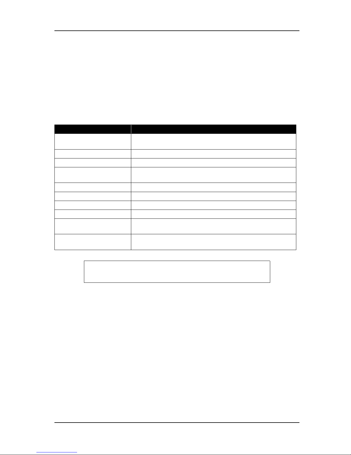
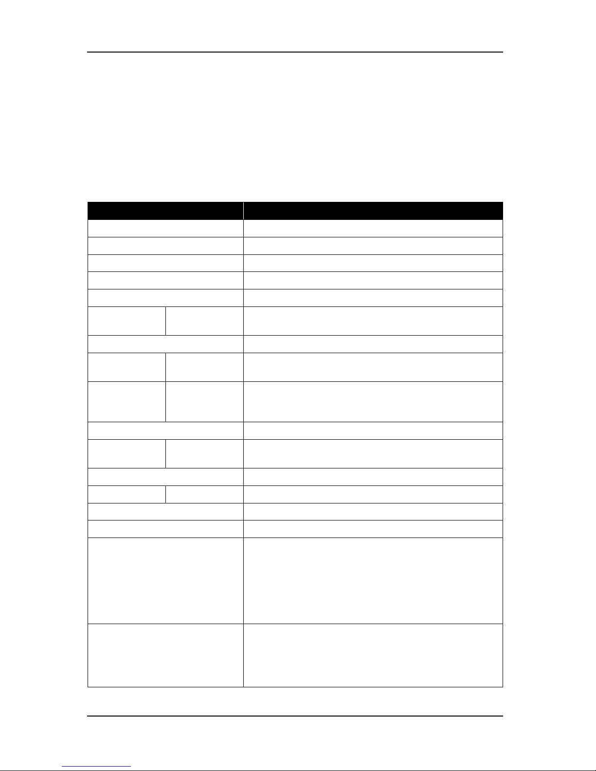
2. Manual Configuration
Section Contents
1 Safety Instructions Explains types of warnings, cautions and warnings labeled on the printer
for the both operators of the printer and maintenance personnel.
2 Product Overview Explains the features, part names, and functions of the printer.
3 Specifications Explains the specifications of the printer.
4 Parts Replacement Explains the procedures of replacement and removal of the service parts
of the printer.
5 Self-Diagnostic Mode Explains the self-diagnostic functions of the printer.
6 Maintenance Mode Explains the maintenance mode of the printer.
7 Adjustment Explains the adjusting procedures of the printer parts.
8 Maintenance Explains daily maintenance of the printer.
9 Troubleshooting Explains troubles that may occur when using the printer and how to
solve them.
10 Appendix Explains the maintenance information and the exploded views for this
printer.
Use the built-in self-diagnostic program to locate a defective part and adjust/
check during maintenance.
Page 6
ValueJet 1304 Service manual
AP-74109 Rev 1.1 4
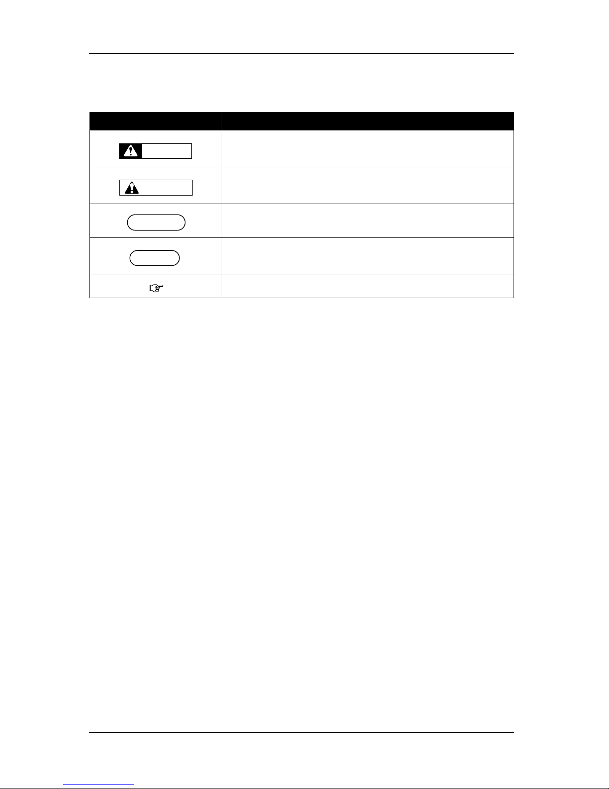
3. Manual Notation
The following symbols are used in this manual for easier understanding of the information.
4. Establishment Date of This Document
This document was established on September 18, 2007.
5. Firmware version covered by this document
Firmware version: Ver.1.00
Symbol Meaning
Must be followed carefully to avoid death or serious bodily injury
Must be observed to avoid slight or moderate bodily injury or damage to
your equipment
Contains important information and useful tips on the operation of the
product
Indicates useful tips for operating or understanding the equipment
Indicates reference pages in this manual
WARNING
CAUTION
NOTE
TIP
Page 7

ValueJet 1304 Service manual
2-3 AP-74109 Rev 1.1
General Table of Contents
1 Safety Instructions
1.1 Introduction. . . . . . . . . . . . . . . . . . . . . . . . . . . . . . . . . . . . . . . . . . . . . . . . . . 1-2
1.2 Warnings, Cautions and Notes . . . . . . . . . . . . . . . . . . . . . . . . . . . . . . . . . . 1-2
1.3 Important Safety Instructions . . . . . . . . . . . . . . . . . . . . . . . . . . . . . . . . . . . 1-3
1.4 Warning Labels . . . . . . . . . . . . . . . . . . . . . . . . . . . . . . . . . . . . . . . . . . . . . . . 1-9
1.4.1 Handling the Warning Labels . . . . . . . . . . . . . . . . . . . . . . . . . . . . . . . . . 1-9
1.4.2 Locations and Types of Warning Labels . . . . . . . . . . . . . . . . . . . . . . . . 1-9
1.5 Operation Labels. . . . . . . . . . . . . . . . . . . . . . . . . . . . . . . . . . . . . . . . . . . . . 1-11
1.5.1 Handling the Operation Labels. . . . . . . . . . . . . . . . . . . . . . . . . . . . . . . 1-11
1.5.2 Locations and Types of Operation Labels . . . . . . . . . . . . . . . . . . . . . . 1-12
2 Product Overview
2.1 Introduction. . . . . . . . . . . . . . . . . . . . . . . . . . . . . . . . . . . . . . . . . . . . . . . . . . 2-2
2.2 Features. . . . . . . . . . . . . . . . . . . . . . . . . . . . . . . . . . . . . . . . . . . . . . . . . . . . . 2-2
2.3 Part Names and Functions. . . . . . . . . . . . . . . . . . . . . . . . . . . . . . . . . . . . . . 2-3
2.3.1 Front Section . . . . . . . . . . . . . . . . . . . . . . . . . . . . . . . . . . . . . . . . . . . . . 2-4
2.3.2 Rear Section. . . . . . . . . . . . . . . . . . . . . . . . . . . . . . . . . . . . . . . . . . . . . . 2-5
2.3.3 Winding unit (Optional). . . . . . . . . . . . . . . . . . . . . . . . . . . . . . . . . . . . . . 2-6
2.3.4 Operation Panel . . . . . . . . . . . . . . . . . . . . . . . . . . . . . . . . . . . . . . . . . . . 2-8
2.4 Printer Status . . . . . . . . . . . . . . . . . . . . . . . . . . . . . . . . . . . . . . . . . . . . . . . 2-11
2.4.1 Normal . . . . . . . . . . . . . . . . . . . . . . . . . . . . . . . . . . . . . . . . . . . . . . . . . 2-11
2.4.2 Setup Menu . . . . . . . . . . . . . . . . . . . . . . . . . . . . . . . . . . . . . . . . . . . . . 2-11
2.4.3 Self-Diagnosis Function . . . . . . . . . . . . . . . . . . . . . . . . . . . . . . . . . . . . 2-11
2.4.4 Maintenance Mode. . . . . . . . . . . . . . . . . . . . . . . . . . . . . . . . . . . . . . . . 2-11
2.4.5 Selecting Panel Language and Panel Temperature. . . . . . . . . . . . . . . 2-12
Page 8

ValueJet 1304 Service manual
AP-74109 Rev 1.1 2-4
3 Specifications
3.1 Introduction. . . . . . . . . . . . . . . . . . . . . . . . . . . . . . . . . . . . . . . . . . . . . . . . . . 3-2
3.2 Product Specifications. . . . . . . . . . . . . . . . . . . . . . . . . . . . . . . . . . . . . . . . . 3-2
3.3 Interface Specifications . . . . . . . . . . . . . . . . . . . . . . . . . . . . . . . . . . . . . . . . 3-4
3.3.1 Network Interface Specifications . . . . . . . . . . . . . . . . . . . . . . . . . . . . . . 3-4
3.4 Choosing a Place for the Printer . . . . . . . . . . . . . . . . . . . . . . . . . . . . . . . . 3-5
4 Parts Replacement
4.1 Introduction. . . . . . . . . . . . . . . . . . . . . . . . . . . . . . . . . . . . . . . . . . . . . . . . . . 4-4
4.2 Removal of Covers . . . . . . . . . . . . . . . . . . . . . . . . . . . . . . . . . . . . . . . . . . . . 4-5
4.2.1 Removing R Side Cover. . . . . . . . . . . . . . . . . . . . . . . . . . . . . . . . . . . . . 4-6
4.2.2 Removing Operation Panel Unit. . . . . . . . . . . . . . . . . . . . . . . . . . . . . . . 4-9
4.2.3 Removing L Side Cover . . . . . . . . . . . . . . . . . . . . . . . . . . . . . . . . . . . . 4-10
4.2.4 Removing Ink Holder (I/H) Cover. . . . . . . . . . . . . . . . . . . . . . . . . . . . . 4-12
4.2.5 Removing Front Cover. . . . . . . . . . . . . . . . . . . . . . . . . . . . . . . . . . . . . 4-14
4.2.6 Removing Top Cover . . . . . . . . . . . . . . . . . . . . . . . . . . . . . . . . . . . . . . 4-15
4.2.7 Removing Media Guide F . . . . . . . . . . . . . . . . . . . . . . . . . . . . . . . . . . 4-16
4.2.8 Removing Media Guide R2 . . . . . . . . . . . . . . . . . . . . . . . . . . . . . . . . . 4-17
4.2.9 Removing Scroller Receiver (L, R). . . . . . . . . . . . . . . . . . . . . . . . . . . . 4-18
4.2.10 Assembling of Scroller Receiver L and R. . . . . . . . . . . . . . . . . . . . . . . 4-20
4.3 Replacement of Board Base Section Components. . . . . . . . . . . . . . . . . 4-23
4.3.1 Removing Connector Panel and Cooling Fan . . . . . . . . . . . . . . . . . . . 4-23
4.3.2 Removing Main Board Bracket . . . . . . . . . . . . . . . . . . . . . . . . . . . . . . 4-24
4.3.3 Replacing Main Board Assembly . . . . . . . . . . . . . . . . . . . . . . . . . . . . . 4-29
4.3.4 Replacing HEATER CONT board assembly . . . . . . . . . . . . . . . . . . . . 4-30
4.3.5 Replacing HEATER RELAY board assembly . . . . . . . . . . . . . . . . . . . 4-32
4.3.6 Replacing Power Board Assembly. . . . . . . . . . . . . . . . . . . . . . . . . . . . 4-35
4.3.7 Replacing Fuse . . . . . . . . . . . . . . . . . . . . . . . . . . . . . . . . . . . . . . . . . . 4-38
4.3.8 Replacing Inlet Assembly. . . . . . . . . . . . . . . . . . . . . . . . . . . . . . . . . . . 4-41
4.4 Replacement of PF Driving Section Components. . . . . . . . . . . . . . . . . . 4-44
4.4.1 Replacing PF Motor Assembly. . . . . . . . . . . . . . . . . . . . . . . . . . . . . . . 4-44
4.4.2 Replacing PF_ENC Assembly . . . . . . . . . . . . . . . . . . . . . . . . . . . . . . . 4-47
4.4.3 Replacing PF_ENC Scale . . . . . . . . . . . . . . . . . . . . . . . . . . . . . . . . . . 4-48
4.4.4 Replacing Heater and Thermistor Assembly . . . . . . . . . . . . . . . . . . . . 4-49
Page 9

ValueJet 1304 Service manual
2-5 AP-74109 Rev 1.1
4.5 Replacement of CR Driving Section Components. . . . . . . . . . . . . . . . . . 4-51
4.5.1 CR Motor Assembly . . . . . . . . . . . . . . . . . . . . . . . . . . . . . . . . . . . . . . . 4-51
4.5.2 Replacing CR Origin Point Sensor . . . . . . . . . . . . . . . . . . . . . . . . . . . . 4-52
4.5.3 Replacing Lever Sensor. . . . . . . . . . . . . . . . . . . . . . . . . . . . . . . . . . . . 4-54
4.5.4 Replacing T Fence . . . . . . . . . . . . . . . . . . . . . . . . . . . . . . . . . . . . . . . . 4-55
4.5.5 Replacing CR Driven Pulley . . . . . . . . . . . . . . . . . . . . . . . . . . . . . . . . . 4-58
4.5.6 Replacing Pressure Arm Assembly . . . . . . . . . . . . . . . . . . . . . . . . . . 4-460
4.6 Replacement of Head Section Components . . . . . . . . . . . . . . . . . . . . . . 4-61
4.6.1 Replacing Print Head . . . . . . . . . . . . . . . . . . . . . . . . . . . . . . . . . . . . . . 4-61
4.6.2 Replacing Cutter Holder Assembly . . . . . . . . . . . . . . . . . . . . . . . . . . . 4-66
4.7 Replacement of Maintenance Section Components . . . . . . . . . . . . . . . . 4-71
4.7.1 Removing Maintenance Base Assembly . . . . . . . . . . . . . . . . . . . . . . . 4-71
4.7.2 Replacing Maintenance Assembly . . . . . . . . . . . . . . . . . . . . . . . . . . . . 4-76
4.7.3 Replacing Cleaner Head (Cleaning Wiper) . . . . . . . . . . . . . . . . . . . . . 4-77
4.8 Replacement of Ink Supply Section Components. . . . . . . . . . . . . . . . . . 4-79
4.8.1 Replacing Ink Holder (I/H) Assembly . . . . . . . . . . . . . . . . . . . . . . . . . . 4-79
4.8.2 Replacing Ink Sensor Assembly. . . . . . . . . . . . . . . . . . . . . . . . . . . . . . 4-82
4.8.3 Replacing Cover Sensor Assembly . . . . . . . . . . . . . . . . . . . . . . . . . . . 4-85
4.8.4 Replacing Heater Junction Board. . . . . . . . . . . . . . . . . . . . . . . . . . . . . 4-87
4.9 Replacement of Frame Section Components . . . . . . . . . . . . . . . . . . . . . 4-89
4.9.1 Replacing Suction Fan Assembly. . . . . . . . . . . . . . . . . . . . . . . . . . . . . 4-89
4.9.2 Replacing P_REAR Sensor Assembly . . . . . . . . . . . . . . . . . . . . . . . . . 4-90
4.10 Replacement of Cable Guide Section Components . . . . . . . . . . . . . . . . 4-91
4.10.1 Replacing CR Board Assembly . . . . . . . . . . . . . . . . . . . . . . . . . . . . . . 4-91
4.10.2 Replacing Ink Tube . . . . . . . . . . . . . . . . . . . . . . . . . . . . . . . . . . . . . . . 4-93
4.10.3 Replacing CR Tape Wire . . . . . . . . . . . . . . . . . . . . . . . . . . . . . . . . . . . 4-97
4.11 Replacing accessory unit. . . . . . . . . . . . . . . . . . . . . . . . . . . . . . . . . . . . . . 4-88
4.11.1 Replacing level switch (waste fluid) . . . . . . . . . . . . . . . . . . . . . . . . . . . 4-89
4.12 Replacing Take up unit. . . . . . . . . . . . . . . . . . . . . . . . . . . . . . . . . . . . . . . 4-102
4.12.1 Removing Tension arm . . . . . . . . . . . . . . . . . . . . . . . . . . . . . . . . . . . 4-103
4.12.2 Removing take up unit fixing plate . . . . . . . . . . . . . . . . . . . . . . . . . . . 4-104
4.12.3 Removing take up unit cover . . . . . . . . . . . . . . . . . . . . . . . . . . . . . . . 4-105
4.12.4 Replacing scroller. . . . . . . . . . . . . . . . . . . . . . . . . . . . . . . . . . . . . . . . 4-108
4.12.5 Replacing VJ take up unit CNT board assembly . . . . . . . . . . . . . . . . 4-109
4.12.6 Replacing CR_HP sensor, lever sensor. . . . . . . . . . . . . . . . . . . . . . . 4-117
4.12.7 Replacing peripheral devices of VJ take up unit motor assembly . . . 4-120
Page 10

ValueJet 1304 Service manual
AP-74109 Rev 1.1 2-6
5 Self-Diagnosis Mode
5.1 Introduction. . . . . . . . . . . . . . . . . . . . . . . . . . . . . . . . . . . . . . . . . . . . . . . . . . 5-4
5.2 Preparation . . . . . . . . . . . . . . . . . . . . . . . . . . . . . . . . . . . . . . . . . . . . . . . . . . 5-4
5.2.1 Preparations on Machine . . . . . . . . . . . . . . . . . . . . . . . . . . . . . . . . . . . . 5-4
5.2.2 Starting Up . . . . . . . . . . . . . . . . . . . . . . . . . . . . . . . . . . . . . . . . . . . . . . . 5-5
5.3 Operations in Self-Diagnosis Mode . . . . . . . . . . . . . . . . . . . . . . . . . . . . . . 5-6
5.3.1 Operating Self-Diagnosis Mode . . . . . . . . . . . . . . . . . . . . . . . . . . . . . . . 5-6
5.3.2 Diagnosis Items in Self-Diagnosis Menu . . . . . . . . . . . . . . . . . . . . . . . . 5-8
5.4 Platen Adjustment Menu . . . . . . . . . . . . . . . . . . . . . . . . . . . . . . . . . . . . . . 5-10
5.5 Inspection Menu . . . . . . . . . . . . . . . . . . . . . . . . . . . . . . . . . . . . . . . . . . . . . 5-11
5.5.1 Memory Size Menu . . . . . . . . . . . . . . . . . . . . . . . . . . . . . . . . . . . . . . . 5-12
5.5.2 Version Menu. . . . . . . . . . . . . . . . . . . . . . . . . . . . . . . . . . . . . . . . . . . . 5-13
5.5.3 Operation Panel Menu . . . . . . . . . . . . . . . . . . . . . . . . . . . . . . . . . . . . . 5-14
5.5.4 Sensor Menu . . . . . . . . . . . . . . . . . . . . . . . . . . . . . . . . . . . . . . . . . . . . 5-15
5.5.5 Encoder Menu . . . . . . . . . . . . . . . . . . . . . . . . . . . . . . . . . . . . . . . . . . . 5-17
5.5.6 Fan Menu. . . . . . . . . . . . . . . . . . . . . . . . . . . . . . . . . . . . . . . . . . . . . . . 5-17
5.5.7 History Menu . . . . . . . . . . . . . . . . . . . . . . . . . . . . . . . . . . . . . . . . . . . . 5-18
5.5.8 Head Waveform Menu . . . . . . . . . . . . . . . . . . . . . . . . . . . . . . . . . . . . . 5-21
5.6 Ink Charging Menu . . . . . . . . . . . . . . . . . . . . . . . . . . . . . . . . . . . . . . . . . . . 5-22
5.7 Adjustment Menu . . . . . . . . . . . . . . . . . . . . . . . . . . . . . . . . . . . . . . . . . . . . 5-23
5.7.1 CR return position adjustment menu . . . . . . . . . . . . . . . . . . . . . . . . . . 5-25
5.7.2 Head Nozzle Check Menu . . . . . . . . . . . . . . . . . . . . . . . . . . . . . . . . . . 5-26
5.7.3 Skew Check Menu . . . . . . . . . . . . . . . . . . . . . . . . . . . . . . . . . . . . . . . . 5-28
5.7.4 Head Slant Check Menu . . . . . . . . . . . . . . . . . . . . . . . . . . . . . . . . . . . 5-29
5.7.5 Voltage Adjustment . . . . . . . . . . . . . . . . . . . . . . . . . . . . . . . . . . . . . . . 5-33
5.7.6 Uni-D / Bi-D Low and High Adjustment . . . . . . . . . . . . . . . . . . . . . . . . 5-36
5.7.7 Side Margin Adjustment Menu. . . . . . . . . . . . . . . . . . . . . . . . . . . . . . . 5-42
5.7.8 Test Printing Menu. . . . . . . . . . . . . . . . . . . . . . . . . . . . . . . . . . . . . . . . 5-43
5.7.9 HeadWash Menu . . . . . . . . . . . . . . . . . . . . . . . . . . . . . . . . . . . . . . . . . 5-44
5.7.10 Software Counter Initialization Menu . . . . . . . . . . . . . . . . . . . . . . . . . . 5-45
5.7.11 Feed Pitch Check Menu. . . . . . . . . . . . . . . . . . . . . . . . . . . . . . . . . . . . 5-46
5.7.12 Solid Print Menu. . . . . . . . . . . . . . . . . . . . . . . . . . . . . . . . . . . . . . . . . . 5-47
5.8 Cleaning Menu . . . . . . . . . . . . . . . . . . . . . . . . . . . . . . . . . . . . . . . . . . . . . . 5-48
Page 11

ValueJet 1304 Service manual
2-7 AP-74109 Rev 1.1
5.9 Sample Printing Menu . . . . . . . . . . . . . . . . . . . . . . . . . . . . . . . . . . . . . . . . 5-49
5.9.1 Adjustment pattern ALL . . . . . . . . . . . . . . . . . . . . . . . . . . . . . . . . . . . . 5-50
5.9.2 Parameter ALL . . . . . . . . . . . . . . . . . . . . . . . . . . . . . . . . . . . . . . . . . . . 5-50
5.9.3 Error history . . . . . . . . . . . . . . . . . . . . . . . . . . . . . . . . . . . . . . . . . . . . . 5-50
5.9.4 Dot pattern . . . . . . . . . . . . . . . . . . . . . . . . . . . . . . . . . . . . . . . . . . . . . . 5-51
5.10 Time Check . . . . . . . . . . . . . . . . . . . . . . . . . . . . . . . . . . . . . . . . . . . . . . . . . 5-52
5.11 Parameter Menu . . . . . . . . . . . . . . . . . . . . . . . . . . . . . . . . . . . . . . . . . . . . . 5-52
5.11.1 Parameter Initialization Menu. . . . . . . . . . . . . . . . . . . . . . . . . . . . . . . . 5-53
5.11.2 Parameter Update Menu . . . . . . . . . . . . . . . . . . . . . . . . . . . . . . . . . . . 5-56
5.12 Servo Setting. . . . . . . . . . . . . . . . . . . . . . . . . . . . . . . . . . . . . . . . . . . . . . . . 5-64
5.13 Endurance Running Menu . . . . . . . . . . . . . . . . . . . . . . . . . . . . . . . . . . . . . 5-67
5.13.1 CR Motor Endurance Menu . . . . . . . . . . . . . . . . . . . . . . . . . . . . . . . . . 5-68
5.13.2 PF Motor Endurance Menu . . . . . . . . . . . . . . . . . . . . . . . . . . . . . . . . . 5-69
5.13.3 Pump Endurance Menu . . . . . . . . . . . . . . . . . . . . . . . . . . . . . . . . . . . . 5-70
5.13.4 Print Head Endurance (Nozzle Print) Menu . . . . . . . . . . . . . . . . . . . . . 5-71
5.13.5 General Endurance Menu . . . . . . . . . . . . . . . . . . . . . . . . . . . . . . . . . . 5-72
5.13.6 Endurance Running Check Menu . . . . . . . . . . . . . . . . . . . . . . . . . . . . 5-73
5.14 Media Feed Menu . . . . . . . . . . . . . . . . . . . . . . . . . . . . . . . . . . . . . . . . . . . . 5-73
5.15 ExControl Menu . . . . . . . . . . . . . . . . . . . . . . . . . . . . . . . . . . . . . . . . . . . . . 5-74
5.15.1 Version . . . . . . . . . . . . . . . . . . . . . . . . . . . . . . . . . . . . . . . . . . . . . . . . . 5-74
5.15.2 Sensor . . . . . . . . . . . . . . . . . . . . . . . . . . . . . . . . . . . . . . . . . . . . . . . . . 5-75
5.15.3 Heater. . . . . . . . . . . . . . . . . . . . . . . . . . . . . . . . . . . . . . . . . . . . . . . . . . 5-76
5.15.4 History . . . . . . . . . . . . . . . . . . . . . . . . . . . . . . . . . . . . . . . . . . . . . . . . . 5-76
5.16 PaperInitial Menu . . . . . . . . . . . . . . . . . . . . . . . . . . . . . . . . . . . . . . . . . . . . 5-77
6 Maintenance Mode 2
6.1 Introduction. . . . . . . . . . . . . . . . . . . . . . . . . . . . . . . . . . . . . . . . . . . . . . . . . . 6-2
6.2 Operations in Maintenance Mode 2. . . . . . . . . . . . . . . . . . . . . . . . . . . . . . . 6-2
6.2.1 Starting Up the Maintenance Mode 2. . . . . . . . . . . . . . . . . . . . . . . . . . . 6-2
6.2.2 Operating Maintenance Mode 2 . . . . . . . . . . . . . . . . . . . . . . . . . . . . . . . 6-3
6.3 Maintenance Menu . . . . . . . . . . . . . . . . . . . . . . . . . . . . . . . . . . . . . . . . . . . . 6-3
6.3.1 Counter Display Menu . . . . . . . . . . . . . . . . . . . . . . . . . . . . . . . . . . . . . . 6-4
6.3.2 Counter Initialization Menu. . . . . . . . . . . . . . . . . . . . . . . . . . . . . . . . . . . 6-6
6.3.3 Counter Print Menu . . . . . . . . . . . . . . . . . . . . . . . . . . . . . . . . . . . . . . . . 6-8
6.3.4 Media Feed Menu . . . . . . . . . . . . . . . . . . . . . . . . . . . . . . . . . . . . . . . . . 6-8
Page 12

ValueJet 1304 Service manual
AP-74109 Rev 1.1 2-8
7 Adjustment
7.1 Introduction. . . . . . . . . . . . . . . . . . . . . . . . . . . . . . . . . . . . . . . . . . . . . . . . . . 7-3
7.2 Adjustment Item . . . . . . . . . . . . . . . . . . . . . . . . . . . . . . . . . . . . . . . . . . . . . . 7-3
7.3 Working with Mutoh Maintenance Engineer Assistant. . . . . . . . . . . . . . . 7-8
7.3.1 Parameter Backup . . . . . . . . . . . . . . . . . . . . . . . . . . . . . . . . . . . . . . . . 7-12
7.3.2 Jigs and Tools . . . . . . . . . . . . . . . . . . . . . . . . . . . . . . . . . . . . . . . . . . . 7-12
7.3.3 Required Environment . . . . . . . . . . . . . . . . . . . . . . . . . . . . . . . . . . . . . 7-12
7.3.4 Receiving Parameters . . . . . . . . . . . . . . . . . . . . . . . . . . . . . . . . . . . . . 7-19
7.3.5 Firmware Installation . . . . . . . . . . . . . . . . . . . . . . . . . . . . . . . . . . . . . . 7-21
7.3.6 Sending Parameters . . . . . . . . . . . . . . . . . . . . . . . . . . . . . . . . . . . . . . 7-28
7.3.7 Sub Controller Installation . . . . . . . . . . . . . . . . . . . . . . . . . . . . . . . . . . 7-29
7.3.8 Date & Time Setting. . . . . . . . . . . . . . . . . . . . . . . . . . . . . . . . . . . . . . . 7-31
7.4 PF Speed Reduction Belt Tension Adjustment . . . . . . . . . . . . . . . . . . . . 7-32
7.4.1 Jigs and Tools . . . . . . . . . . . . . . . . . . . . . . . . . . . . . . . . . . . . . . . . . . . 7-32
7.4.2 Adjustment Procedure . . . . . . . . . . . . . . . . . . . . . . . . . . . . . . . . . . . . . 7-32
7.5 PF Encoder Assembly Position Adjustment . . . . . . . . . . . . . . . . . . . . . . 7-33
7.5.1 Adjustment Procedure . . . . . . . . . . . . . . . . . . . . . . . . . . . . . . . . . . . . . 7-33
7.6 CR Belt Tension Adjustment . . . . . . . . . . . . . . . . . . . . . . . . . . . . . . . . . . . 7-35
7.7 Head Alignment (Horizontal Height) . . . . . . . . . . . . . . . . . . . . . . . . . . . . . 7-36
7.8 Head Alignment (Vertical Slant) . . . . . . . . . . . . . . . . . . . . . . . . . . . . . . . . 7-38
7.9 Cutter Holder Height Adjustment . . . . . . . . . . . . . . . . . . . . . . . . . . . . . . . 7-40
7.9.1 Jigs and Tools . . . . . . . . . . . . . . . . . . . . . . . . . . . . . . . . . . . . . . . . . . . 7-40
7.9.2 Adjustment Procedure . . . . . . . . . . . . . . . . . . . . . . . . . . . . . . . . . . . . . 7-40
7.10 PG Height Adjustment . . . . . . . . . . . . . . . . . . . . . . . . . . . . . . . . . . . . . . . . 7-43
7.10.1 Jigs and Tools . . . . . . . . . . . . . . . . . . . . . . . . . . . . . . . . . . . . . . . . . . . 7-43
7.10.2 Adjustment Procedure . . . . . . . . . . . . . . . . . . . . . . . . . . . . . . . . . . . . . 7-43
7.11 Media Sensor Sensitivity Adjustment . . . . . . . . . . . . . . . . . . . . . . . . . . . 7-45
7.11.1 P_EDGE Sensor Sensitivity Adjustment . . . . . . . . . . . . . . . . . . . . . . . 7-45
7.11.2 P_REAR Sensor Adjustment . . . . . . . . . . . . . . . . . . . . . . . . . . . . . . . . 7-48
Page 13

ValueJet 1304 Service manual
2-9 AP-74109 Rev 1.1
8 Maintenance
8.1 Introduction. . . . . . . . . . . . . . . . . . . . . . . . . . . . . . . . . . . . . . . . . . . . . . . . . . 8-2
8.2 Periodical Services. . . . . . . . . . . . . . . . . . . . . . . . . . . . . . . . . . . . . . . . . . . . 8-3
8.2.1 Periodical Replacement Parts . . . . . . . . . . . . . . . . . . . . . . . . . . . . . . . . 8-3
8.2.2 Parts need to be checked or replaced . . . . . . . . . . . . . . . . . . . . . . . . . . 8-4
8.3 Part Life Information. . . . . . . . . . . . . . . . . . . . . . . . . . . . . . . . . . . . . . . . . . . 8-5
8.4 Lubrication/Bonding. . . . . . . . . . . . . . . . . . . . . . . . . . . . . . . . . . . . . . . . . . . 8-7
8.5 Transportation of Printer . . . . . . . . . . . . . . . . . . . . . . . . . . . . . . . . . . . . . . . 8-8
9 Troubleshooting
9.1 Introduction. . . . . . . . . . . . . . . . . . . . . . . . . . . . . . . . . . . . . . . . . . . . . . . . . . 9-2
9.2 Troubleshooting with Error Messages . . . . . . . . . . . . . . . . . . . . . . . . . . . . 9-2
9.2.1 Operation Status . . . . . . . . . . . . . . . . . . . . . . . . . . . . . . . . . . . . . . . . . . 9-3
9.2.2 Errors with Message. . . . . . . . . . . . . . . . . . . . . . . . . . . . . . . . . . . . . . . . 9-5
9.2.3 Errors Requiring Reboot. . . . . . . . . . . . . . . . . . . . . . . . . . . . . . . . . . . . . 9-9
9.2.4 Error Messages During File Transmission . . . . . . . . . . . . . . . . . . . . . . 9-25
9.3 Troubleshooting Without Error Messages . . . . . . . . . . . . . . . . . . . . . . . . 9-30
9.3.1 Initial Operation Problems . . . . . . . . . . . . . . . . . . . . . . . . . . . . . . . . . . 9-30
9.3.2 Media Feed Problems . . . . . . . . . . . . . . . . . . . . . . . . . . . . . . . . . . . . . 9-39
9.3.3 Printing Problems . . . . . . . . . . . . . . . . . . . . . . . . . . . . . . . . . . . . . . . . . 9-41
9.3.4 Noise Problems . . . . . . . . . . . . . . . . . . . . . . . . . . . . . . . . . . . . . . . . . . 9-59
9.3.5 Online Function Problems . . . . . . . . . . . . . . . . . . . . . . . . . . . . . . . . . . 9-62
9.3.6 Other Problems . . . . . . . . . . . . . . . . . . . . . . . . . . . . . . . . . . . . . . . . . . 9-65
9.3.7 Troubleshooting for a dedicated network software. . . . . . . . . . . . . . . . 9-67
10 Appendix
10.1 Introduction. . . . . . . . . . . . . . . . . . . . . . . . . . . . . . . . . . . . . . . . . . . . . . . . . 10-2
10.2 Wiring Diagram . . . . . . . . . . . . . . . . . . . . . . . . . . . . . . . . . . . . . . . . . . . . . . 10-2
10.3 Jigs and Tools. . . . . . . . . . . . . . . . . . . . . . . . . . . . . . . . . . . . . . . . . . . . . . . 10-3
10.3.1 Required Tools . . . . . . . . . . . . . . . . . . . . . . . . . . . . . . . . . . . . . . . . . . . 10-3
10.4 Operation Panel Messages (Bilingual List) . . . . . . . . . . . . . . . . . . . . . . . 10-4
10.5 Exploded View. . . . . . . . . . . . . . . . . . . . . . . . . . . . . . . . . . . . . . . . . . . . . . . 10-9
Page 14

ValueJet 1304 Service manual
AP-74109 Rev 1.1 2-10
Page 15

ValueJet 1304 Service manual
1-1 AP-74109 Rev 1.1
1 Safety Instructions
1.1 Introduction............................................................................................. 1- 2
1.2 Warnings, Cautions and Notes.............................................................. 1- 2
1.3 Important Safety Instructions ................................................................ 1- 3
1.4 Warning Labels ....................................................................................... 1- 9
1.4.1 Handling the Warning Labels......................................................... 1-9
1.4.2 Locations and Types of Warning Labels........................................ 1-9
1.5 Operation Labels................................................................................... 1- 11
1.5.1 Handling the Operation Labels .................................................... 1-11
1.5.2 Locations and Types of Operation Labels ................................... 1-12
Page 16
ValueJet 1304 Service manual
AP-74109 Rev 1.1 1-2
1.1 Introduction
This chapter explains the meaning of safety terms for personnel who installs, operates, or maintains this
equipment, important safety instructions, and the warning labels attached to the equipment.
WARNING
Make sure to follow all instructions and warnings on this manual when installing, operating,
or maintaining the equipment.
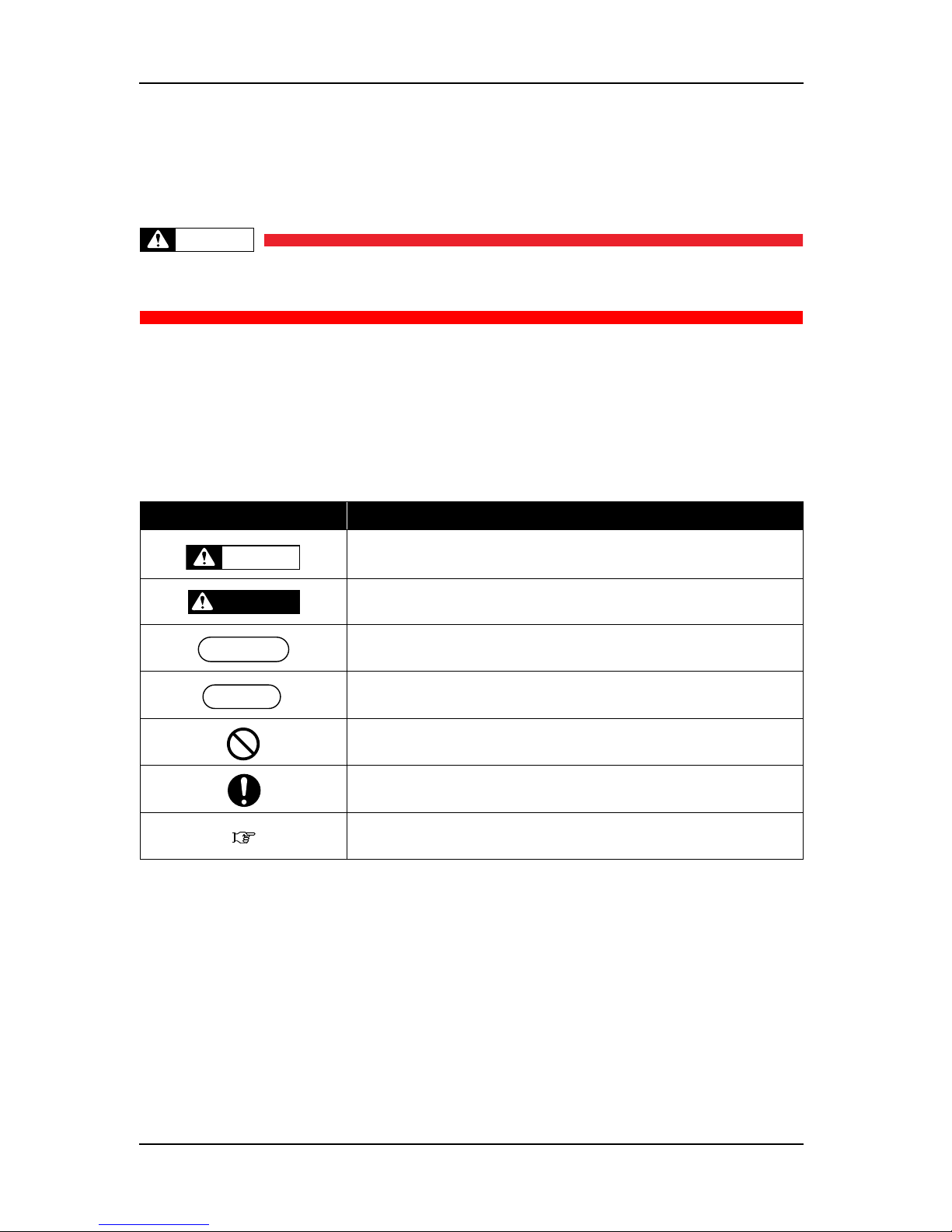
1.2 Warnings, Cautions and Notes
Safety terms in this manual and the contents of warning labels attached to the printer are categorized into the
following three types depending on the degree of risk (or the scale of accident).
Read the following explanations carefully, and follow the instructions in this manual.
Table 1-1 Safety Terms Descriptions
Safety terms Details
Must be followed carefully to avoid death or serious bodily injury
Must be observed to avoid slight or moderate bodily injury or damage to
whole or part of the product
Contains important information and useful tips on the operation of the
product
Indicates useful tips for operating or understanding the printer
Indicates "prohibited" operations
Indicates required operations
Indicates reference page in this manual
WARNING
DANGER
NOTE
TIP
Page 17
ValueJet 1304 Service manual
1-3 AP-74109 Rev 1.1
1.3 Important Safety Instructions
General safety instructions that must be observed to use the equipment safely are explained below.
WARNING
Do not place the printer in the following areas. Doing so may result in the printer
tipping or falling over and causing injury.
• Unstable surfaces
• Angled place
• Areas subject to vibration by other equipment
Do not stand on or place heavy objects on your printer. Doing so may result in the
printer tipping or falling over and causing injury.
Do not cover the ventilation hole of your printer with cloth, such as a blanket or table
cloth. Doing so could obstruct ventilation and cause fire.
Do not place the printer in humid and dusty areas. Doing so may result in electrical
shock or fire.
Do not use damaged power cable. It could lead to an electric shock and fire.
Do not take out or insert power plug with a wet hand. This could lead to an electric
shock.
Make sure that the following is performed before parts replacement.
• Turn off the power of the printer.
• Remove the power cable from the power outlet.
Not doing so may cause electric shock or damage to the electric circuit.
• Unplug the cables connected to the printer.
Failure to do so could result in damage to the printer.
Do not connect an earth wire to the following places.
• Gas pipe
There is a possibility of ignition and explosion.
• Earth wire of telephone cables and lightning rods
Heavy current might flow whenever a lightning strikes.
• Water pipe and faucet
The earth might not work if a plastic pipe is connected in the middle of the metal
pipe.
Do not store combustible materials on Platen while performing the heater operation.
It could lead to fire.
Do not spill flammable liquid over platen. This could lead to fire.
Page 18
ValueJet 1304 Service manual
AP-74109 Rev 1.1 1-4
Do not insert or drop metal or flammable objects into the printer through openings
such as a fresh air inlet. It could lead to an electric shock and fire.
When foreign substances or liquids such as water entered the printer, do not use
the printer as it is. It could lead to an electric shock and fire. Immediately turn OFF
the power switch, disconnect the power plug from the electric socket.
Be sure to use the power cable supplied with the printer. If other power cables are
used, it would cause an electric shock or fire.
Make sure to use only the specified power supply (AC 100 V - 120 V or AC 220 V 240 V). If the power supply other than the specified voltage is used, it could cause
an electric shock and fire.
Take power for the printer directly from the power socket (AC 100 V - 120 V or AC
220 V - 240 V). Do not use complex multiple plugs on the same socket. This could
generate heat and might cause fire.
Be sure to use a dedicated power socket with earth wire for the power supply, and
connect it to the earth wire. If the earth wire is not connected, an electric shock or
fire may occur.
The waste fluid from the printer is a waste oil (waste ink) of industrial waste. Proper
waste fluid disposal according to industrial waste disposal laws and ordinances of
your local governments are required. Consign disposal of waste fluids to specialized
processor.
Page 19

ValueJet 1304 Service manual
1-5 AP-74109 Rev 1.1
CAUTION
Assembling and disassembling of the printer are possible only for the parts that
disassembling procedures are shown in this manual. Do not disassemble any frame
parts or parts that disassembling procedures are not shown in this manual.
Doing so may cause trouble that cannot be restored, as the printer is originally
assembled in the factory with a high accuracy of 1/100 mm.
Do not touch the elements on the circuit board with bare hands.
Doing so may cause static electricity and break the elements.
Do not press the transparent film on the damper assembly with your hands. Doing
so may discharge the ink filled inside the damper assembly.
Be careful not to damage the transparent film on the damper assembly.
Do not touch the nozzles of the print head. Make sure that the nozzles do not get
any dust.
There are some remaining ink in the tubes. Be careful that the ink is not spilled from
the tube outlet onto the printer or items close to the printer.
If you need to operate the printer with the cover removed for maintenance, be
careful not to get hurt by the driving parts.
Never lube the printer mechanism with lube other than that designated by MUTOH.
Doing so may damage the parts or shorten the lifetime.
If the power board assembly needs to be removed, remove the power cable and
wait for 5 minutes or more before taking it out; this will discharge the residual
electrical charge of the electrolytic capacitor.
Touching the board before the capacitor discharges may cause electric shock.
When connecting or removing an FFC type cable on a main board assembly
connector, make sure to connect or remove the cable perpendicular to the
connector.
Connecting or removing at a slant angle may damage, break or short-circuit the
inner terminal of the connector. That may damage the elements on the board.
When connecting or removing an FFC type cable on the CR board assembly
connector, make sure to connect or remove the cable perpendicular to the
connector.
Connecting or removing at a slant angle may damage, break or short-circuit the
inner terminal of the connector. That may damage the elements on the board.
Make sure there is sufficient space around the printer when performing
maintenance work.
Maintenance must be done by more than two persons for the following work.
• When disassembling or reassembling the product and the optional stand
• When packing the printer for transportation
Page 20

ValueJet 1304 Service manual
AP-74109 Rev 1.1 1-6
Pay attention to the following points, while handling power cable.
• Do not do anything forcefully on the power cable.
• Do not keep heavy objects on the power cable.
• Do not bend, twist or pull the power cable by force.
• Do not route the power cable near heating appliances.
Pay attention to the following points while handling power supply plug. Any
mishandling of the power cable could cause a fire.
• Make sure that no foreign substances such as dust etc. are stuck to the power
plug.
• The power plug is firmly inserted to the edge of the power socket.
Be careful not to pinch your fingers when opening/closing the front cover or
maintenance cover.
While handling ink cartridge, pay attention so that the ink does not get into eyes or
stick to the skin. If the ink gets into the eyes or sticks to the skin, immediately wash
it off with water. It might possibly cause irritation and light inflammation of eyes. In
case of any abnormality, consult a physician immediately.
Do not disassemble ink cartridges. If disassembled, there is a possibility that the ink
might come into contact with eyes or skin.
Do not operate the media loading lever during initial operation. The carriage portion
may touch the pressurizing roller portion causing a malfunction.
Do not touch the media guide during printing. It is hot and may cause a burn.
Be careful that your fingers are not caught in the driven section of the winding unit.
Pay attention to the following points when you cut roll media. Mishandling the razor
blade may cause a cut on your finger or hand.
• When you hold media, do not place your finger on the media cut groove.
• Move the razor blade along the media cut groove.
Do not apply Jetwash, thinner, benzine, or alcohol to the printer parts, excluding
listed below. Such use may result in printer malfunction
• Inside the maintenance cover
• Surface of the print head
Be careful that moisture does not enter the printer. There is a possibility that electric
circuit inside the printer is short circuited.
Page 21
ValueJet 1304 Service manual
1-7 AP-74109 Rev 1.1
While cleaning with the cleaning wiper
• Do not touch the cleaning wiper and head cap unit.
Head cleaning may not be operated correctly because of the grease attached.
• Make sure to wipe the print head with a dry poly-knit wiper.
A wet poly-knit wiper may cause the print head to clog.
• Do not use clean sticks.
Attached dust may damage the print head.
Be careful the followings when cleaning the outer of the print head:
• Do not touch the print head nozzle part.
Such operation may damage the print head.
• Do not touch the tip of the clean stick.
Fat sticks to the clean stick may damage the print head.
• Do not sink the clean stick into water.
Such operation may damage the print head.
• Do not re-use any used clean stick.
Attached dust may damage the print head.
Do not slant the printer body, prop it against a wall or turn it upside down. There is
a possibility that ink inside the printer may leak. Moreover, normal operation after
shifting (to these positions) cannot be guaranteed.
Unpack or move the printer by more than two person.
When taking this printer out of the package box, make sure to remove the vinyl
sheet and hold the handles on the side of the printer. If the printer is lifted with the
vinyl sheet attached, there is a possibility that the printer falls slipping from hands
and gets damaged.
When you do not use the printer for a long period, make sure to pull out the power
plug from the power socket for safety.
Make sure to connect an earth wire to the earth connection which meets the following
standards.
• Earth terminal of power socket
• Earth wire with copper plate which is buried at 650 mm or more, deep in the ground.
• Earth terminal which grounded properly (earth resistance: 100
Ω or less).
Keep the work area well-ventilated. This prevents fire and operators from feeling
sick from bad air.
Execute the following operation by more than two persons:
• Setting the winding unit.
When printing is finished, the media guide and the platen are at high temperature. Wait
until the media guide and the platen cool off.
Page 22

ValueJet 1304 Service manual
AP-74109 Rev 1.1 1-8
When cleaning the printer, be sure to turn OFF the power and disconnect the power
plug.
Move the printer maintaining a horizontal position.
Be sure to operate the following before attaching option units.
• Turn the printer power off.
• Unplug the power cable.
• Unplug the cables connected to the printer.
Otherwise, the printer or computer may be damaged.
• Remove the static electricity by touching the metal part of the printer from your
cloth or body.
Electric part such as RAM may be damaged.
Do not touch the board elements when attaching option units. The elements become
high temperature and may cause the burn.
Page 23
ValueJet 1304 Service manual
1-9 AP-74109 Rev 1.1
1.4 Warning Labels
The handling, attachment locations, and types of warning labels are explained below.
Warning labels are attached to areas where care should be taken. Read and understand the positions and
contents thoroughly before maintenance operation.
1.4.1 Handling the Warning Labels
Make sure to note the following when handling the warning labels.
NOTE
• Make sure that all warning labels can be recognized. If text or illustrations cannot be seen clearly,
clean or replace the label.
• When cleaning warning labels, use a cloth with water or neutral detergent. Do not use a solvent or
gasoline.
• If a warning label is damaged, lost, or cannot be recognized, replace the label.
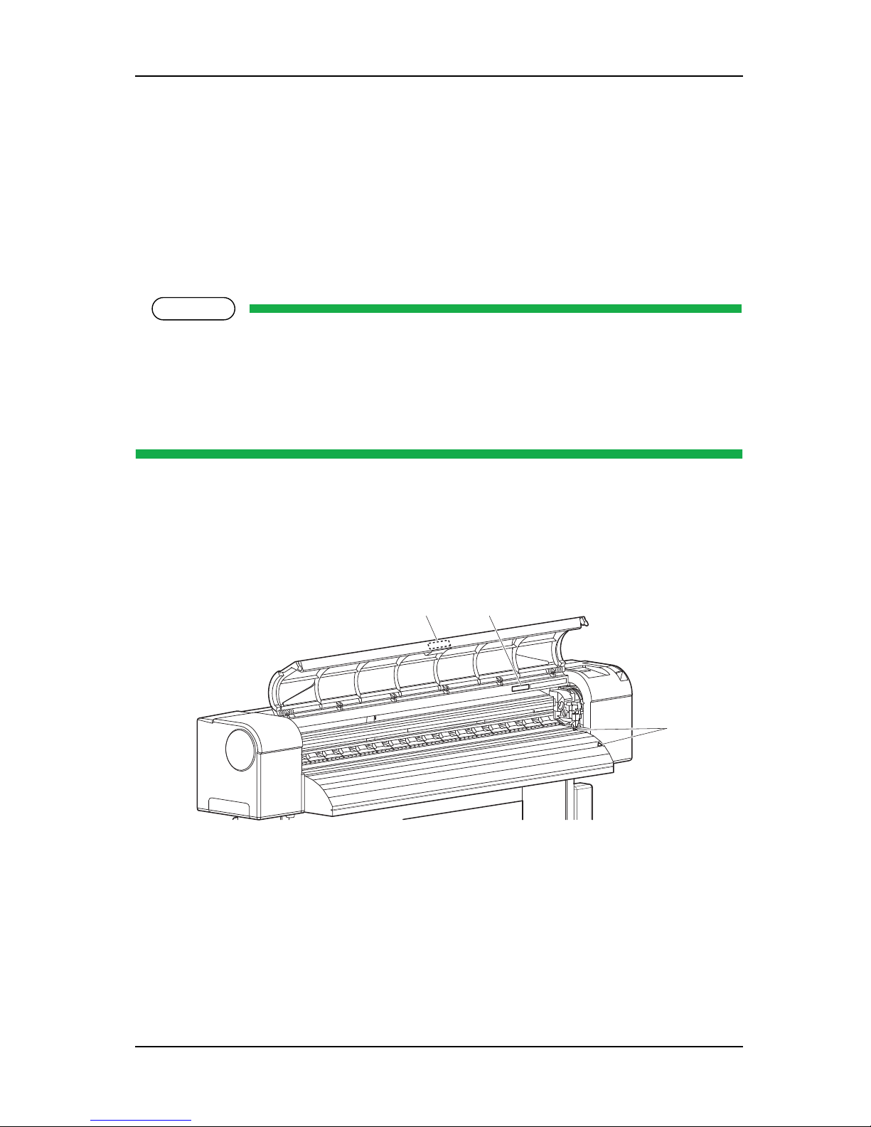
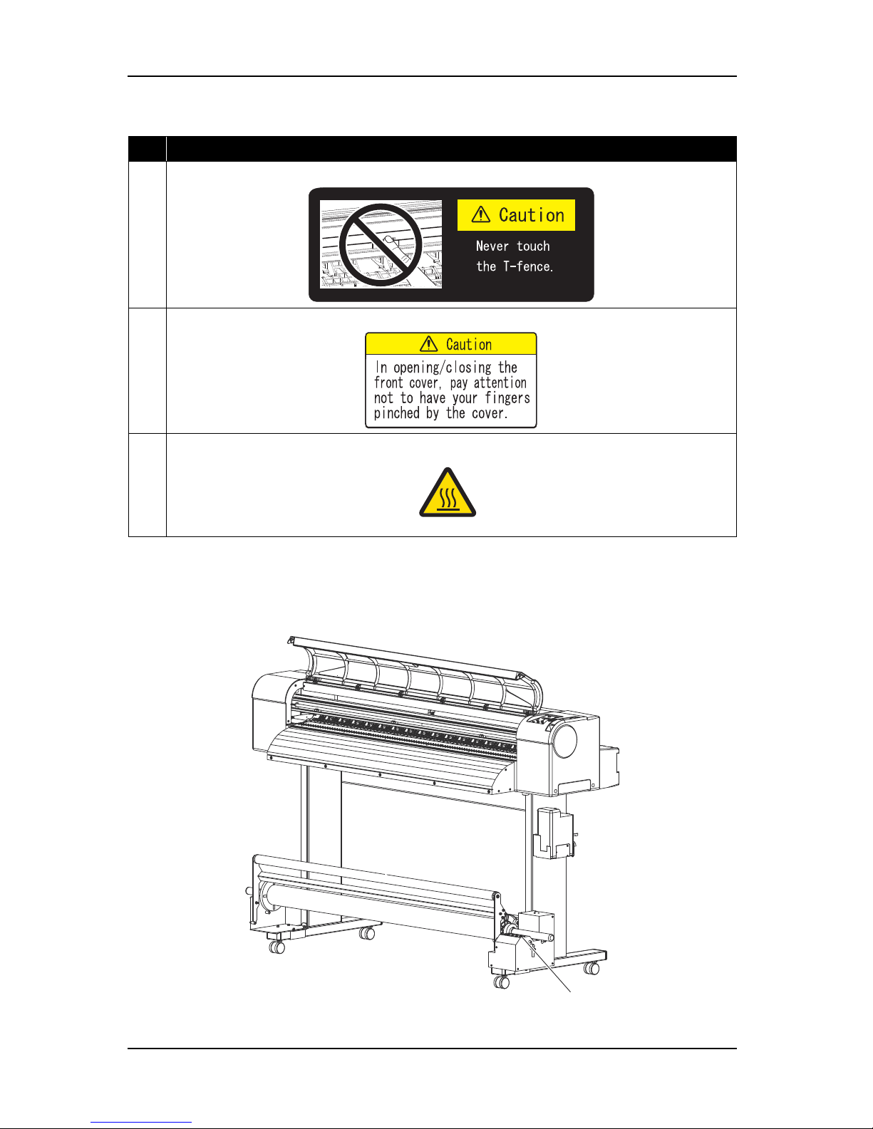
1.4.2 Locations and Types of Warning Labels
The locations of warning labels are shown below.
(1) Main Body
21
3
Page 24
ValueJet 1304 Service manual
AP-74109 Rev 1.1 1-10
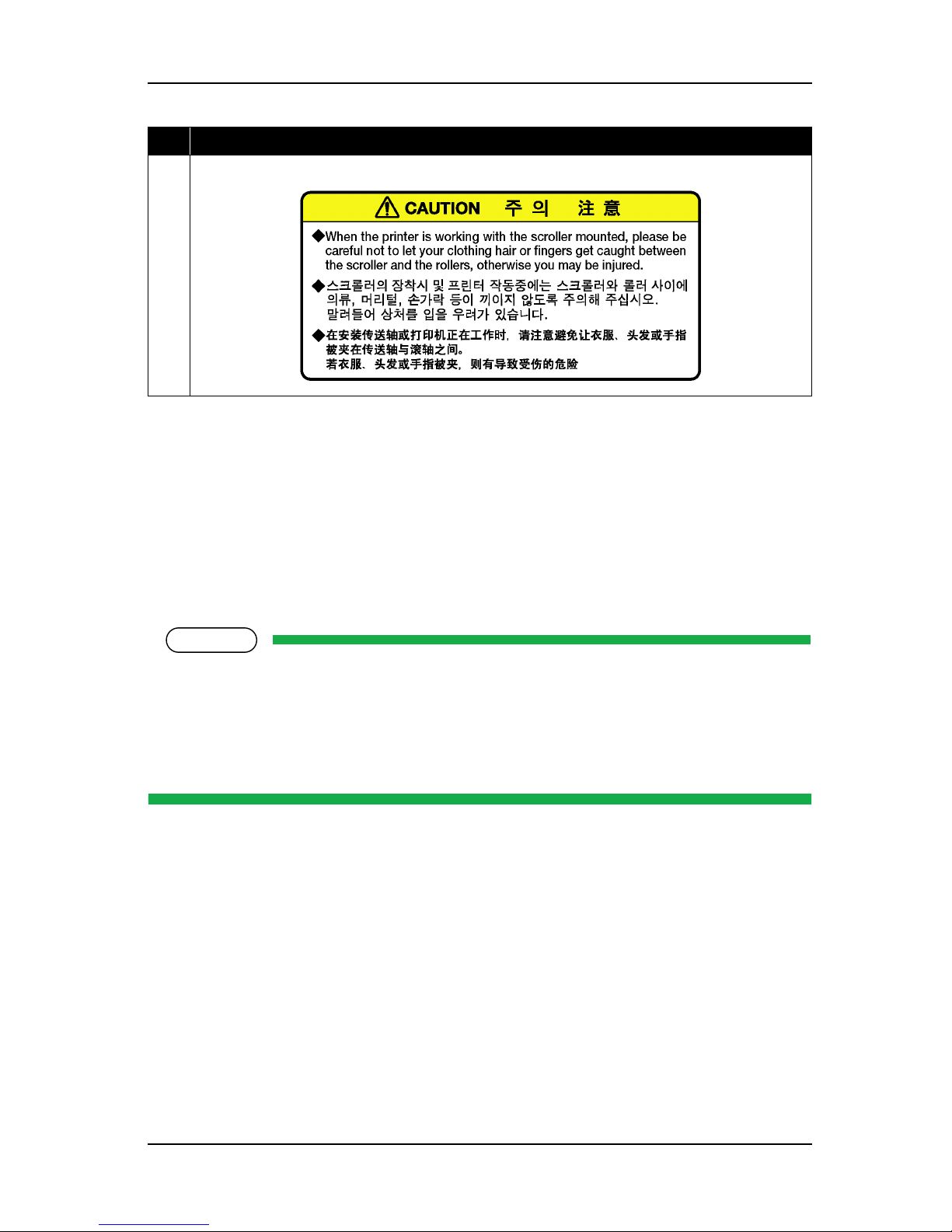
(2) Winding unit
The locations of warning labels on the winding unit are shown below.
Table 1-2 List of Warning Labels
No. Warning label type
1
(T fence handling caution)
2
(Front cover open/close caution)
3
(High temperature caution)
1
Page 25
ValueJet 1304 Service manual
1-11 AP-74109 Rev 1.1
1.5 Operation Labels
This chapter describes the operation labels including their types and attaching positions.
The operation labels are attached on the product to provide the brief instructions for the particularly important
operations. Learn the instructions and the attaching positions before operation.
1.5.1 Handling the Operation Labels
Make sure to note the following when handling the operation labels.
NOTE
• Make sure that all operation labels can be recognized. If text or illustrations cannot be seen clearly,
clean or replace the label.
• When cleaning operation labels, use a cloth with water or neutral detergent. Do not use a solvent
or gasoline.
• If an operation label is damaged, lost, or cannot be recognized, replace the label.
No. Warning label type
1
(Catching caution)
Page 26
ValueJet 1304 Service manual
AP-74109 Rev 1.1 1-12
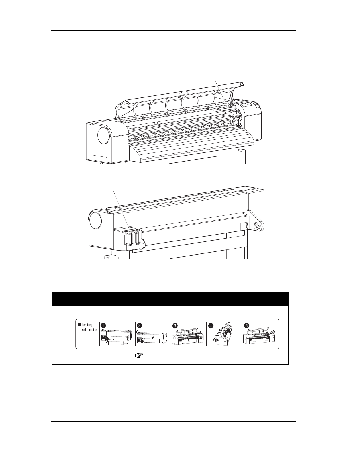
1.5.2 Locations and Types of Operation Labels
The locations of operation labels are shown below.
Table 1-3 List of Operation Labels
No. Operation label type
1
(Roll media setting)
"Operation manual" Setting Roll Media
1
2
Page 27
ValueJet 1304 Service manual
1-13 AP-74109 Rev 1.1
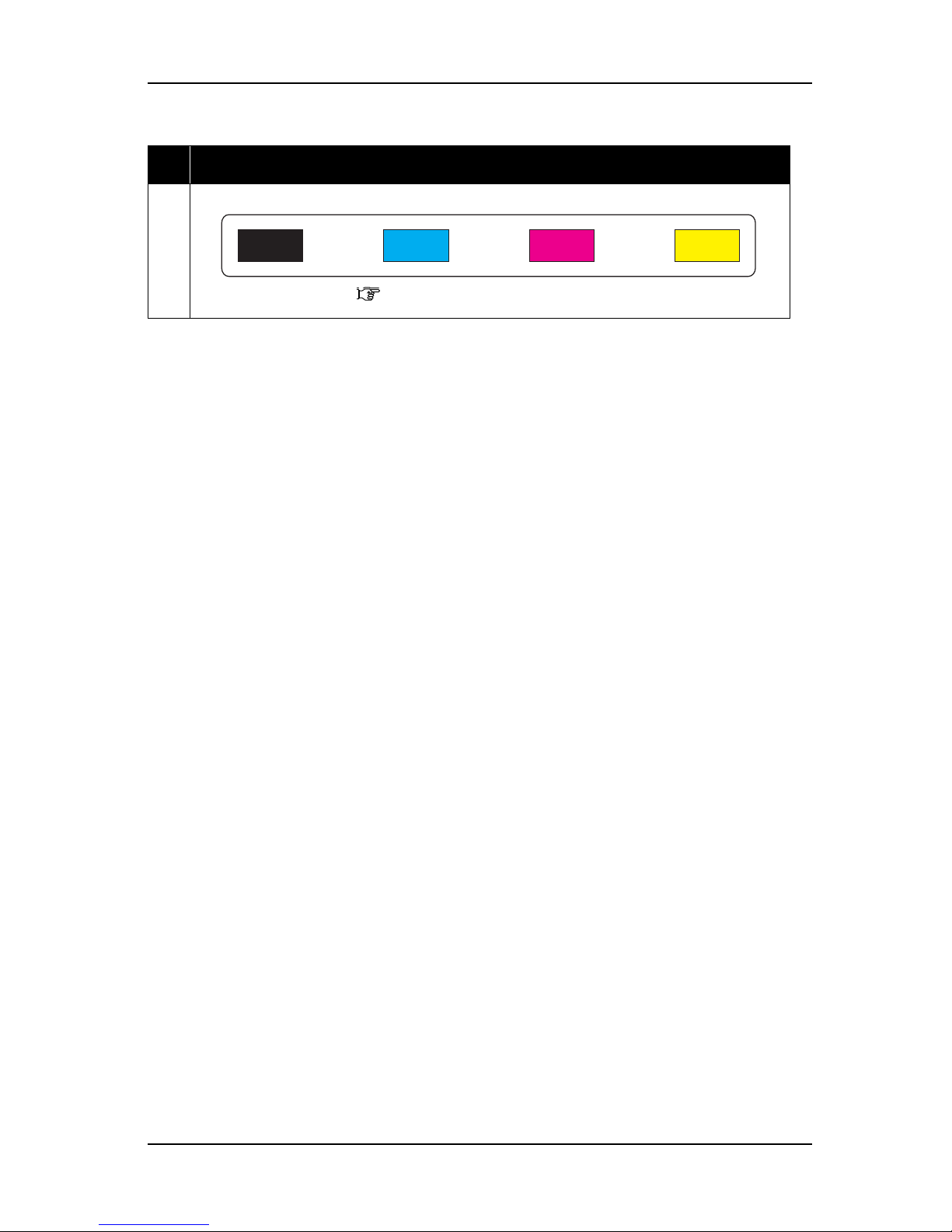
2
(Ink arrangement)
"Operation manual" Replacing Ink Cartridges
Table 1-3 List of Operation Labels (Continued)
No. Operation label type
Page 28

ValueJet 1304 Service manual
AP-74109 Rev 1.1 1-14
Page 29

ValueJet 1304 Service manual
2-1 AP-74109 Rev 1.1
2 Product Overview
2.1 Introduction............................................................................................. 2- 2
2.2 Features................................................................................................... 2- 2
2.3 Part Names and Functions..................................................................... 2- 3
2.3.1 Front Section ................................................................................. 2-4
2.3.2 Rear Section.................................................................................. 2-5
2.3.3 Winding unit (Optional) .................................................................. 2-6
2.3.4 Operation Panel............................................................................. 2-8
2.4 Printer Status ........................................................................................ 2- 11
2.4.1 Normal ......................................................................................... 2-11
2.4.2 Setup Menu ................................................................................. 2-11
2.4.3 Self-Diagnosis Function............................................................... 2-11
2.4.4 Maintenance Mode ...................................................................... 2-11
2.4.5 Selecting Panel Language and Panel Temperature .................... 2-12
Page 30

ValueJet 1304 Service manual
AP-74109 Rev 1.1 2-2
2.1 Introduction
This chapter explains the features, part names, and functions of the printer.
2.2 Features
The features of the printer are explained below.
(1) Fast Print
The new print head adopted on this printer performs fast to print images.
Also, this printer prints up to 1355.5mm (when uni-directional print mode) or 1336.5mm (when bi-directional
print mode) in width.
(2) Variety of Print Media
The height of the print head position can be set high/low, so that this model can print on the media of which
thickness is between 0.08 and 1.00 mm.
(3) Vivid Color Reproduction
For vivid color reproduction, this model has high-capacity (220 ml) 4 color ink cartridges with exclusive
smart IC chip on it. With the IC chip, you can manage the ink level of the cartridges and can get better
productivity.
Also, with the variable dot method, richer color expression can be enhanced.
(4) Multi-Heater System
The media-heating system which have been equipped to PJ series is changed to match the solvent ink. There
are 3 heaters on Pre / Platen / After positions and improved the ink flexibility and drying property.
(5) Effective Utilization of Media
The JOG function is featured, which allows to set random print start positions. Printed media can be reprinted
and blank areas on the media can be put to effective use.
Page 31

ValueJet 1304 Service manual
2-3 AP-74109 Rev 1.1
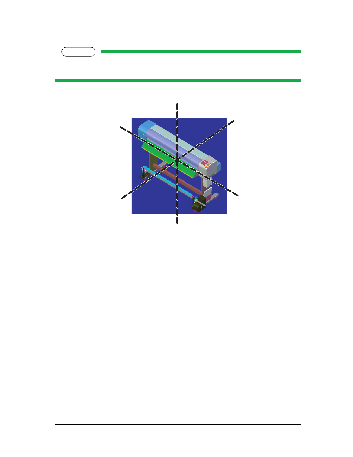
2.3 Part Names and Functions
Part names and functions are explained below.
NOTE
For the directions described in this document, refer to the following figure.
Rear
Upper
Lower
Right
Front
Left
Page 32
ValueJet 1304 Service manual
AP-74109 Rev 1.1 2-4
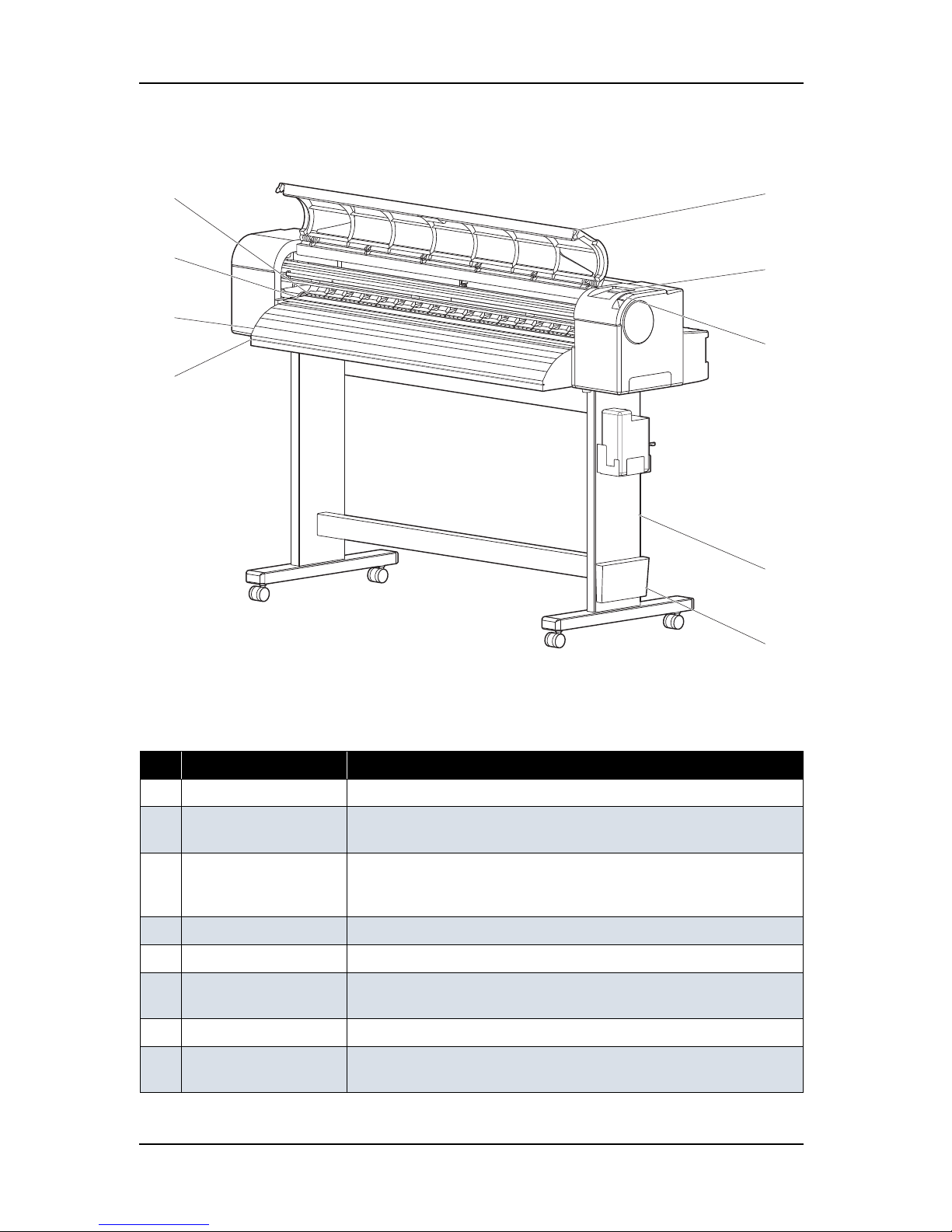
2.3.1 Front Section
Table 2-1 Part Names and Functions of Front Section
No. Name Function
1 Media set lever This lever is used to fix or release the media.
2 Operation panel This panel is used to set operational conditions, the status of the printer,
and other functions.
3 Front cover This cover keeps the operator safe from the drive parts of the printer while
it is operating.This is opened/closed when replacing the cutter or paper is
jammed.This should be closed during normal use.
4 Stand This stand is used to set the printer on the level surface of the floor.
5 Book holder This holder is used to store printed guide such as Quick Reference Guide.
6 Media Guide This guide is used to feed media smoothly when setting media and
printing.
7 Media cut guide This guide groove is used to cut printed media straight.
8 Pressure roller This is inside the front cover.
Presses and supports the media in the width when printing.
Page 33

ValueJet 1304 Service manual
2-5 AP-74109 Rev 1.1
2.3.2 Rear Section
9 Platen This is inside the front cover.
There are heaters (platen heater) inside to dry ink.
Table 2-2 Part Names and Functions of Rear Section
No. Name Function
1 AC inlet For inserting the power cable plug.
2 Network interface
connector
Connector to connect a network interface cable.
3
USB connector This printer does not support the connector.
4 Scroller receiver The scroller is set here when using roll media.
5 Media feed slot Insert media from here when feeding media.
6 Ink cartridge slot This holds the ink cartridge.
7 Media guide Supports the media to be feed smoothly when media setting and printing.
There are pre heaters inside to warm the media.
8 Waste fluid tank This is a tank that contains the waste ink.
Table 2-1 Part Names and Functions of Front Section (Continued)
No. Name Function
1
4
23
K
C
6
M
Y
5
7
4
8
9
Page 34
ValueJet 1304 Service manual
AP-74109 Rev 1.1 2-6
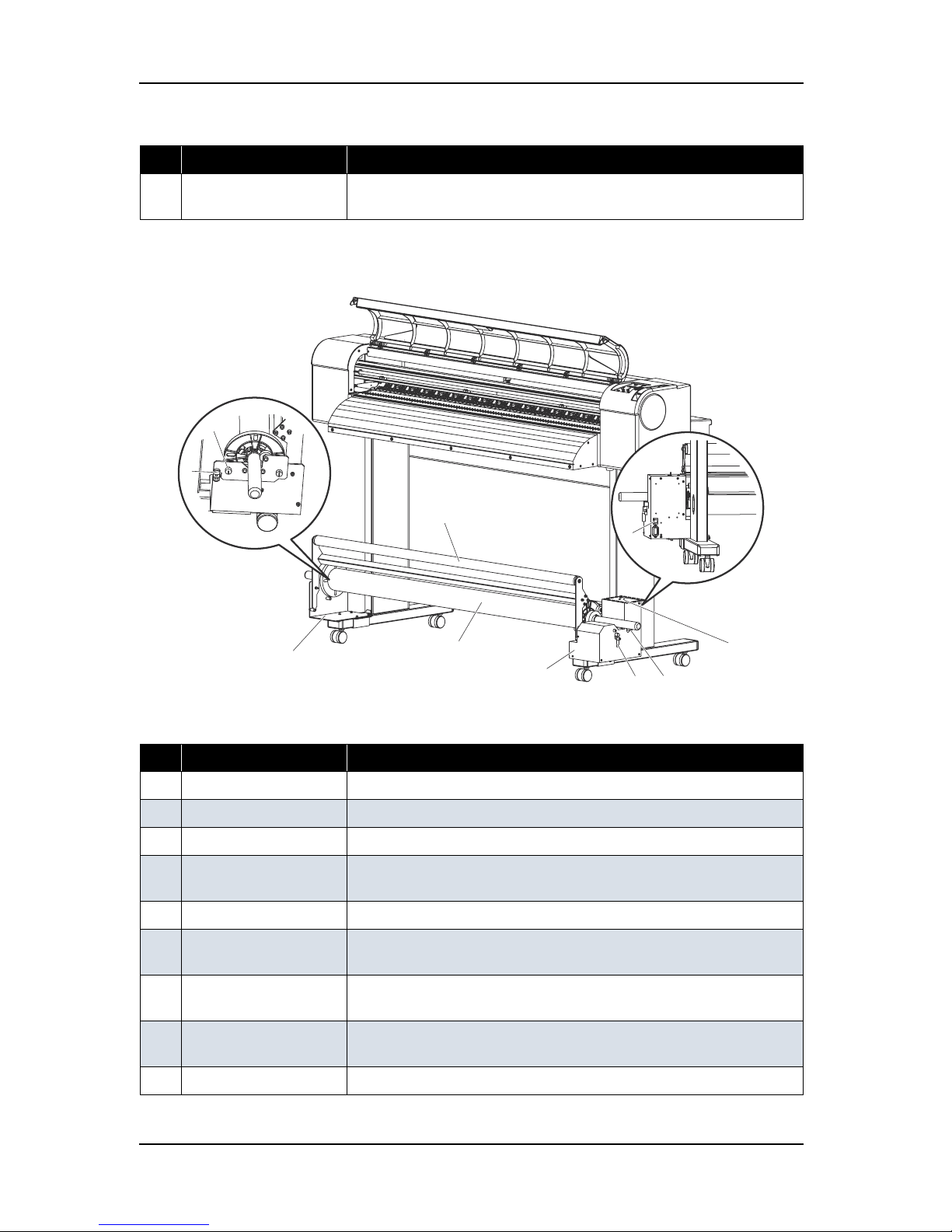
2.3.3 Winding unit
9 Waste fluid valve Open this valve to discharge the waste fluid from the waste fluid tank.
In other case, close the valve.
Table 2-3 Part Names and Functions of Winding Unit
No. Name Function
1 Winding unit Winds the printed media.
2 Cushioning roller Loads the printed media to the winding unit.
3 Scroller receiver Used when setting the scroller of the winding unit.
4 Scroller release lever Releases the scroller from the winding unit, allowing you to turn the
scroller with your hand.
5 Scroller Used when winding the printed media.
6 Scroller height fixing
screw
Fix the height of the scroller receiver.
7 Scroller height
adjustment screw
Adjust the height of the scroller receiver.
8 Horizontal adjustment
screw
Adjust the side position of the scroller.
9 Power switch Used when turning the power ON and OFF.
Table 2-2 Part Names and Functions of Rear Section (Continued)
No. Name Function
48
5
3
2
10
1
7
9
6
Page 35

ValueJet 1304 Service manual
2-7 AP-74109 Rev 1.1
10 Operation panel Used for setting operation conditions, display of unit status.
"Winding unit for VJ-1304"
Table 2-3 Part Names and Functions of Winding Unit
No. Name Function
Page 36

ValueJet 1304 Service manual
AP-74109 Rev 1.1 2-8
2.3.4 Operation Panel
The operation panel is used to set operational conditions, display the status of the printer, and set other
functions.
The names and functions of the operation keys and status lamps are explained below.
TIP
Operation manual
8, 9
3
15
17
16
6
5
11
12
1
13
14
10
27
4
Page 37

ValueJet 1304 Service manual
2-9 AP-74109 Rev 1.1
(1) Operation Keys
NOTE
Some keys have multiple functions and names depending on the printer status (normal or setup menu
display). See "2.4 Printer Status" p.2-11 for more details.
No. Name Normal Setup menu display
1
[Menu] key
Changes the LCD monitor display to
setup menu status.
Changes the setup menu display
status to normal status.
2 [Enter] key - - Selects the menu to be set and shifts
to the next hierarchy.
- Determines and saves the parameter
value.
[Cleaning] key If held down for 2 seconds or more,
starts cleaning the printer head.
-
3 [Cancel] key - During plotting: Terminates printing
forcibly and deletes 1 file of
remaining data.
- During reception/analysis: Deletes
the data that has been already
received/analyzed and ignores 1 file
of data received after that.
-
- Returns to the previous menu
hierarchy. Changed parameter values
are disabled.
- Changes the setup menu display
status to normal status.
4 [<] key Sets the media type.
• - The lamp for the cleaning mode
lights on (green).
-Changes the setting value in the
following menu:
• Origin setting menu
[Nozzle Check] key If held down for 2 seconds or more,
starts checking the printer nozzle.
-
5 [>] key Sets the cleaning mode.
- The lamp for the media type lights
on (green).
Displays lower rank menu items.
6 [Backward ↑ ] key Feeds the media in the reverse
direction.
-
[ + ] key - -Changes the menu in forward order.
-Changes the setting value in forward
order.
-Increases the value when inputting
setting value.
7[Forward
↓ ] key Feeds the media in the forward
direction.
-
[ - ] key - - Changes the menu in the reverse
direction.
- Decreases the value when inputting
values.
Page 38
ValueJet 1304 Service manual
AP-74109 Rev 1.1 2-10
(2) LCD Monitor and Status Lamps
8 [Power] key Turns the printer on and off. Turns the printer on and off.
No. Name Color Status Function
9 Power lamp Green On The printer is switched on.
Blinking An error has occurred. The contents will be displayed on the
LCD monitor.
Off The printer is switched off.
10 Data lamp Red On - The printer is analyzing received data.
- The printer is printing data.
Blinking The printer is receiving data.
Off The printer is not receiving, analyzing or printing data.
11 High lamp Green On The print head height is set to High position.
Off The print head height is set to Low position.
12 Low lamp Green On The print head height is set to Low position.
Off The print head height is set to High position.
13 Wave lamp Red On The effect menu is set to Wave.
Off The effect menu is set to either Fine or SuperFine.
14 Fine & S.Fine
lamp
Red On The effect menu is set to either Fine or SuperFine.
Off The effect menu is set to Wave.
15 Strong lamp Green On - The cleaning mode is set to Strong.
- When the Normal lamp is also on, the cleaning mode is set
to Economy.
Off - The effect menu is set to Wave.
- When the Strong lamp is also on, the cleaning mode is set
to Economy quality.
16 Normal lamp Green On - The cleaning mode is set to Normal.
- When the Strong lamp is also on, the cleaning mode is set
to Economy quality.
Off The cleaning mode is set to Strong.
17 LCD monitor - - This monitor displays the operation status and error
messages of the printer.
No. Name Normal Setup menu display
Page 39
ValueJet 1304 Service manual
2-11 AP-74109 Rev 1.1
2.4 Printer Status
The status of the printer is explained below.
2.4.1 Normal
Indicates that the printer can print when media is loaded.
Each setup concerning printing can be operated by using operation panel.
TIP
Operation manual
2.4.2 Setup Menu
Each setup concerning printing can be operated by using operation panel.
The settings required for normal printing are usually made on the printer driver or application, but can also
be made using the operation panel.
TIP
Operation manual
2.4.3 Self-Diagnosis Function
Indicates that each settings concerning printing using the operation panel. Names and functions of the
operation panel keys are the same as those of setup menu display.
TIP
"5 Self-Diagnosis Mode" p.5-1
2.4.4 Maintenance Mode
Indicates that each setup concerning to the life counter on this printer can be operated by using the operation
panel. Names and functions of the operation panel keys are the same as those of setup menu display.
TIP
"6 Maintenance Mode 2" p.6-1
Page 40
ValueJet 1304 Service manual
AP-74109 Rev 1.1 2-12
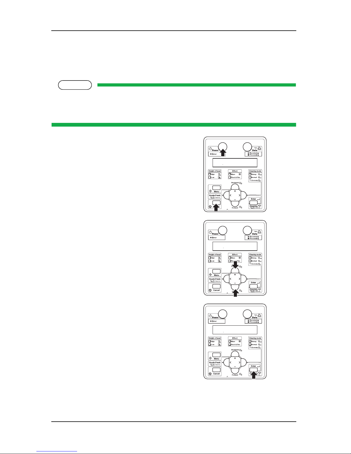
2.4.5 Selecting Panel Language and Panel Temperature
This section describes how to select the language displayed in the operation panel.
Follow the steps below to select the language.
NOTE
You can choose panel language and panel temperature as follows.
Language:Japanese or English
Temperature:Celsius or Fahrenheit
1. Press [Power] key in the operation panel while
pressing [Cancel] key.
2. Press [Setting/value +] key or [Setting/value -]
key in the operation panel to modify the value.
3. To save the modified value, press [Enter] key in
the operation panel.
* panel temperature appears after panel
language. Operation is same as before.
Page 41

ValueJet 1304 Service manual
3-1 AP-74109 Rev 1.1
3 Specifications
3.1 Introduction............................................................................................. 3- 2
3.2 Product Specifications........................................................................... 3- 2
3.3 Interface Specifications.......................................................................... 3- 4
3.3.1 Network Interface Specifications.................................................... 3-4
3.4 Choosing a Place for the Printer .......................................................... 3- 5
Page 42
ValueJet 1304 Service manual
AP-74109 Rev 1.1 3-2
3.1 Introduction
This chapter explains the specifications of the product, optional parts, and supplies. Installation environment
requirements are also explained.
3.2 Product Specifications
(1) Main Unit Specifications
Item Specifications
Model name
VJ-1304
Plotting method
On-demand piezo drive
Motor driving method
Firmware servo/DC motor drive
Media feeding method
Multi-point pressure grid roller method
Media fixing method
Pressurizing roller manual-down method
Media supply and
ejection
Roll media
Front feeding/front paper ejection
Media type
Tracing Paper
Roll media outer
diameter
2-inch
150 mm or less
Maximum
loadable media
weight
Roll media
19 kg (41.9 lb) or less
Maximum media width
1371.5 mm (54 in.)
Maximum media
length:
Roll media
50 m (160 ft.)
Maximum plot length
1355 mm (53.3 in.)
Plotting margins Roll media
Top: 3mm, Bottom: 3mm, Left: 3mm, Right: 3mm
Media cutting method
Manual cutting across the media
Head height adjustment
2 levels: Normal and High
Distance accuracy The larger value either ± 0.25 mm or ± 0.1% of moving distance
•Used media: Roll MF-3G
• Plot length: 1355.5 mm (4.45 ft.)
• Operating temperature: 22 to 30ºC (71.6 to 86F)
• Operating humidity: 40 to 60%
•PG: Low
• Plot mode: Graphics1
Right angle accuracy ±0.1mm or less against the moving distance (500.0mm)
•Used media: Roll MF-3G
• Operating temperature: 22 to 30ºC (71.6 to 86F)
• Operating humidity: 40 to 60%
• Plot mode: Graphics1
Page 43

ValueJet 1304 Service manual
3-3 AP-74109 Rev 1.1
CPU
64Bit RISC CPU
Memory
128MB
Command
MH-RTL (RTL-PASS)
Interface
Network Interface (IEEE802.3)
After-heater
OFF / 30 to 50°C (86 to 122F)
Platen heater
OFF / 30 to 50°C (86 to 122F)
Pre-heater
OFF / 30 to 50°C (86 to 122F)
Ink Supply method
Tube supply from separate four separated cartridges
Cartridge
Black, cyan, magenta, yellow: 220ml ± 5ml for each color
Head life expectancy
60 billion dots per nozzle (in case of sequence discharging under the condition
of the temperature of 25
ºC (77F) with no dust)
Environmental conditions
Operation environment
Temperature: 20ºC (68F) to 32ºC (90F)
Humidity: 40% to 60%, with no condensation
Plotting accuracy warranty range
Temperature: 22ºC (71.6F) to 30ºC (86F)
Humidity: 40% to 60%, with no condensation
Rate of change
Temperature: 2ºC/hour or less
Humidity: 5%/hour or less
Storage
environment
Without ink
Temperature: -20ºC (-4F) to 60ºC (140F)
Humidity: 20% to 80%, with no condensation
Storage period: 6 months
With ink
Temperature: -10ºC (14F) to 40ºC (104F)
Humidity: 20% to 80%, with no condensation
Storage period: 6 months
Power source Voltage
AC 90 - 132V ± 10%
Frequency
50Hz/60Hz ± 1Hz
Power
consumption
During Plotting 1260W or less (when heater is ON)
During standby 40W or less (when standby heater is OFF)
Outer dimensions Height
1218mm (48 in.) * including stand
Width
1875 mm (73.8 in.)
Depth
685 mm (27 in.)
Weight Main body
58.0 kg (127.8 lb.)
Stand
21.3 kg (46.9 lb)
Item Specifications
Page 44

ValueJet 1304 Service manual
AP-74109 Rev 1.1 3-4
3.3 Interface Specifications
This section explains the specification of the interfaces Supported for this printer.
3.3.1 Network Interface Specifications
Item Specifications
Network type Ethernet IEEE802.3
Network I/F 10BASE-T / 100BASE-TX Auto-switching
(RJ-45 connector twist pair cable)
MDI / MDI-X Auto-switching
Corresponding
protcol
TCP/IP
Page 45

ValueJet 1304 Service manual
3-5 AP-74109 Rev 1.1
3.4 Choosing a Place for the Printer
WARNING
• Do not place the printer in a location under the following conditions. Doing so may cause
the product to fall, become damaged, or cause injury.
• Unstable surfaces
• Slanted areas
• Locations that are subject to vibration from other product
• Do not stand on the printer or place any heavy objects on it.
Doing so may cause it to fall over, become damaged, or cause injury.
• Do not cover the ventilation hole of the printer with cloth, such as a blanket or table cloth.
Doing so could prevent the printer from ventilating and cause fire.
• Keep the printer away from humid and dusty areas. Failure to do so may result in
electrical shock or fire.
(1) Installation Environment Requirements
Choose a place for printer installation following the requirements of the table below.
Table 3-1 Installation Environment Requirements List
Floor loading capability 2940Pa (300kgf/m2) or over
Electrical
specifications
Voltage AC 90 V - 120 V ± 10%
Frequency 50/60Hz ± 1Hz
Capacity 10A or more
Environmental conditions Temperature Humidity
Operation
environment
20º C (68F) to 32ºC (86F) 40% to 60%, with no condensation
Plotting accuracy
warranty range
22ºC (71.6F) to 30ºC (86F) 40% to 60%, with no condensation
Rate of change 2ºC/hour or less 5%/hour or less
Page 46

ValueJet 1304 Service manual
AP-74109 Rev 1.1 3-6
NOTE
• Avoid the following temperature and humidity conditions. Otherwise, Plotted images may appear
differently from what you expect.
• Places where sudden changes in temperature and humidity are expected, even though the
condition is within the range specified
• Places where direct sunlight or excessive lighting are expected
• Places where air conditioners blow directly
• MUTOH recommends that the printer should be installed where air conditioning can be adjusted
easily.
(2) Required Space
Install the printer on a flat surface that fulfills the following conditions.
• The place to install printer with the optional stand should have enough loading capacity.
NOTE
• For the printer and the optional stand, refer to"3.2 Product Specifications" p.3-2.
• When maintaining the printer, 1000 mm of space is required on the left side of the printer in
addition to the spaces shown below.
* Do not use VJ-1304 without stand.
g
e
a
d
b
c
f
a=500mm
b=1000mm
c=1000mm
d=1000mm
e=1440mm
f=3000mm
g=2660mm
Page 47

ValueJet 1304 Service manual
4-1 AP-74109 Rev 1.1
4 Parts Replacement
4.1 Introduction............................................................................................. 4- 4
4.2 Removal of Covers ................................................................................. 4- 5
4.2.1 Removing R Side Cover ................................................................ 4-6
4.2.2 Removing Operation Panel Unit .................................................... 4-9
4.2.3 Removing L Side Cover............................................................... 4-10
4.2.4 Removing Ink Holder (I/H) Cover................................................. 4-12
4.2.5 Removing Front Cover................................................................. 4-14
4.2.6 Removing Top Cover................................................................... 4-15
4.2.7 Removing Media Guide F............................................................ 4-16
4.2.8 Removing Media Guide R2.......................................................... 4-17
4.2.9 Removing Scroller Receiver (L, R) .............................................. 4-18
4.2.10 Assembling of Scroller Receiver L and R .................................... 4-20
4.3 Replacement of Board Base Section Components ........................... 4- 23
4.3.1 Removing Connector Panel and Cooling Fan.............................. 4-23
4.3.2 Removing Main Board Bracket.................................................... 4-24
4.3.3 Replacing Main Board Assembly................................................. 4-29
4.3.4 Replacing HEATER CONT board assembly................................ 4-30
4.3.5 Replacing HEATER RELAY board assembly .............................. 4-32
4.3.6 Replacing Power Board Assembly............................................... 4-35
4.3.7 Replacing Fuse............................................................................ 4-38
4.3.8 Replacing Inlet Assembly............................................................. 4-41
4.4 Replacement of PF Driving Section Components ............................. 4- 44
4.4.1 Replacing PF Motor Assembly..................................................... 4-44
Page 48

ValueJet 1304 Service manual
AP-74109 Rev 1.1 4-2
4.4.2 Replacing PF_ENC Assembly...................................................... 4-47
4.4.3 Replacing PF_ENC Scale ............................................................ 4-48
4.4.4 Replacing Heater and Thermistor Assembly................................ 4-49
4.5 Replacement of CR Driving Section Components .............................4- 51
4.5.1 CR Motor Assembly...................................................................... 4-51
4.5.2 Replacing CR Origin Point Sensor ............................................... 4-52
4.5.3 Replacing Lever Sensor ............................................................... 4-54
4.5.4 Replacing T Fence ....................................................................... 4-55
4.5.5 Replacing CR Driven Pulley and CR belt ..................................... 4-58
4.5.6 Replacing Pressure Arm Assembly.............................................. 4-60
4.6 Replacement of Head Section Components .......................................4- 61
4.6.1 Replacing Print Head.................................................................... 4-61
4.6.2 Replacing Cutter Holder Assembly............................................... 4-66
4.7 Replacement of Maintenance Section Components ..........................4- 71
4.7.1 Removing Maintenance Base Assembly...................................... 4-71
4.7.2 Replacing Maintenance Assembly ............................................... 4-76
4.7.3 Replacing Cleaner Head (Cleaning Wiper) .................................. 4-77
4.8 Replacement of Ink Supply Section Components..............................4- 79
4.8.1 Replacing Ink Holder (I/H) Assembly............................................ 4-79
4.8.2 Replacing Ink Sensor Assembly................................................... 4-82
4.8.3 Replacing Cover Sensor Assembly.............................................. 4-85
4.8.4 Replacing Heater Junction Board................................................. 4-87
4.9 Replacement of Frame Section Components .....................................4- 89
4.9.1 Replacing Suction Fan Assembly................................................. 4-89
Page 49

ValueJet 1304 Service manual
4-3 AP-74109 Rev 1.1
4.9.2 Replacing P_REAR Sensor Assembly......................................... 4-90
4.10 Replacement of Cable Guide Section Components .......................... 4- 91
4.10.1 Replacing CR Board Assembly.................................................... 4-91
4.10.2 Replacing Ink Tube...................................................................... 4-93
4.10.3 Replacing CR Tape Wire ............................................................. 4-97
4.11 Replacing Accessory Unit.................................................................. 4- 101
4.11.1 Replacing Level Switch (Waste Fluid) ....................................... 4-101
4.12 Replacing Take Up Unit...................................................................... 4- 102
4.12.1 Removing Tension Arm ............................................................. 4-103
4.12.2 Removing Take Up Unit Fixing Plate......................................... 4-104
4.12.3 Removing Take Up Unit Cover .................................................. 4-105
4.12.4 Replacing Scroller...................................................................... 4-108
4.12.5 Replacing VJ Take Up Unit CNT Board Assembly .................... 4-109
4.12.6 Replacing CR_HP Sensor, Lever Sensor.................................. 4-117
4.12.7 Replacing Peripheral Devices of VJ Take Up Unit Motor assy.. 4-120
Page 50
ValueJet 1304 Service manual
AP-74109 Rev 1.1 4-4
4.1 Introduction
This chapter provides information on removal and replacement of service parts.
WARNING
Before starting part replacement, always perform the following operations.
• Turn OFF the machine power.
• Remove the power plug from the outlet.
Otherwise, you may suffer electric shock or the system circuit may be damaged.
• Remove any cables connected to the machine.
Otherwise, the machine may be damaged.
CAUTION
The components in the machine can be disassembled only if so instructed in this manual.
Do not disassemble the frame components and other components that are not instructed to
disassemble in the manual.
The machine has been assembled in the MUTOH factory with extremely high precision up
to 1/100mm. If disassembled inappropriately, it may not restore its normal functionality.
Page 51
ValueJet 1304 Service manual
4-5 AP-74109 Rev 1.1
NOTE
After replacing any service parts, perform necessary lubrication and bonding following the
instructions in section "8.4 Lubrication/Bonding" p.8-7.
Rear
Upper
Lower
Right
Front
Left
Page 52

ValueJet 1304 Service manual
AP-74109 Rev 1.1 4-6
4.2 Removal of Covers
Before replacing any service parts in the machine, you must remove some external covers.
This section describes the procedure to remove covers.
Table 4-1 Cover Component List
No. Part name
1
L side cover
2
Front cover
3
Media guide F
4
R side cover
5
Waste fluid bottle
6
I/H cover
7
Operation panel unit assembly
8
Media guide R2 (rear side)
9
Top cover
1
3
2
4
5
6
7
9
8
(Rear side)
Page 53

ValueJet 1304 Service manual
4-7 AP-74109 Rev 1.1
4.2.1 Removing R Side Cover
1. Move down the pressure lever backward.
2. Remove the pressure lever cap-retaining screw (M4 × 10, P tight binding: 1).
3. Remove the R side cover outer screw (Tapping screw M4
× 8, S tight cup: 2).
表 4-2
No. Part name
1 Pressure lever cap
2 Pressure lever cap screw
(M4
× 10, P tight binding)
表 4-3
No. Part name
1 R side cover
2 Waste fluid unit cover
3 R side cover outer screw
(M4
× 8, P tight cup)
1
2
1
2
3
Page 54

ValueJet 1304 Service manual
AP-74109 Rev 1.1 4-8
4. Remove the waste fluid unit cover-retaining screw (tapping screw M3 × 6, S tight cup: 2)
5. Remove the waste fluid unit cover.
6. Open the front cover.
7. Remove the R side cover inner screw (tapping screw M4
× 12, P tight binding black: 2).
表 4-4
No. Part name
1 Waste fluid cover
2 waste fluid unit cover-retaining
screw (Tapping screw M3
× 6, S
tight cup: 2)
表 4-5
No. Part name
1 R side cover
2 R side cover inner screw
(tapping screw M4
× 12, P tight
binding black)
1
2
2
1
Page 55

ValueJet 1304 Service manual
4-9 AP-74109 Rev 1.1
8. Remove the R side cover rear screw (tapping screw M4 × 12, S tight cup: 2).
9. Return the pressure lever forward and remove the R side cover to the upper right direction.
10. Replace the parts inside the product.
11. To reassemble the unit, reverse the removal procedure.
表 4-6
No. Part name
1 R side cover
2 R side cover rear screw
(tapping screw M4
× 12, S tight
cup)
1
2
Page 56
ValueJet 1304 Service manual
AP-74109 Rev 1.1 4-10
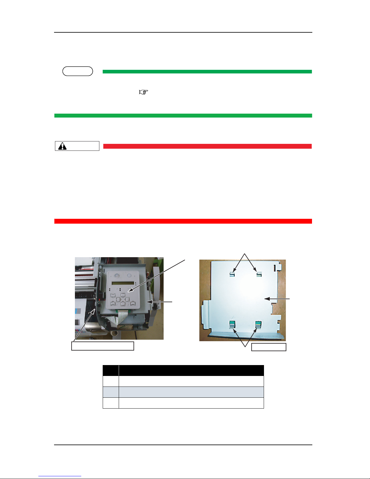
4.2.2 Removing Operation Panel Unit
TIP
Before removing the operation panel unit, perform the following work.
• Removing the R side cover: "4.2.1 Removing R Side Cover" p.4-6
• Unlocking and moving the carriage.
1. Remove the operation panel unit tape wire (FFC).
CAUTION
• Before replacing board or connecting/removing tape wire (FFC), unplug the power cable
and leave the printer for a while. Or board may be damaged by overcurrent.
• When connecting or removing the tape wire (FFC) to the operation panel unit connector,
always pull or push the wire perpendicularly to the connector. Pulling or pushing the wire
slantwise may damage/short/break the terminals in the connectors, resulting in a
breakdown of the on-board devices.
• You can connect/remove the tape wire up to five times.
2. Release the tab on the rear side of the operation panel unit from the panel stay.
3. Remove the operation panel unit.
4. To reassemble the unit, reverse the removal procedure.
No. Part name
1 Operation panel unit
2 Panel stay
3 Operation panel unit-retaining tab
1
2
3
3
Insert a hand from here.
bottom view
2
Page 57

ValueJet 1304 Service manual
4-11 AP-74109 Rev 1.1
4.2.3 Removing L Side Cover
1. Remove the L side cover front screw (tapping screw M4 × 12, P tight binding black: 2).
2. Remove the L side cover rear screw (tapping screw M4 × 8, S tight cup: 2).
3. Remove the L side cover right screw (tapping screw M4
× 8, S tight cup: 2).
NOTE
Before removing the scroller receiver side screw, remove the following part.
• Scroller receiver L:
"4.2.9 Removing Scroller Receiver (L, R)" p.4-18
4. Remove the L side cover scroller receiver side screw (tapping screw M4 × 12, P tight binding black: 1).
表 4-7
No. Part name
1L side cover
2 L side cover inner screw
(tapping screw M4
× 12, P tight
binding black)
表 4-8
No. Part name
1 L side cover
2 L side cover rear screw
(tapping screw M4
× 8, S tight cup)
3 L side cover right screw
(tapping screw M4
× 8, S tight cup)
4 L side cover scroller receiver side
screw (back side)
(tapping screw M4
× 12, P tight
binding black)
1
2
2
2
4
3
1
Page 58

ValueJet 1304 Service manual
AP-74109 Rev 1.1 4-12
5. Remove the L side cover.
6. To reassemble the unit, reverse the removal procedure.
Page 59

ValueJet 1304 Service manual
4-13 AP-74109 Rev 1.1
4.2.4 Removing Ink Holder (I/H) Cover
NOTE
Before removing the ink holder (I/H) cover, remove the following parts.
• R side cover: "4.2.1 Removing R Side Cover" p.4-6
1. Remove the ink cartridge.
2. Remove the I/H cover rear screw (tapping screw M4
× 8, S tight cup: 2).
3. Remove the scroller receiver.
"4.2.9 Removing Scroller Receiver (L, R)" p.4-18
4. Remove the I/H cover side (scroller receiver side) screw (tapping screw M4
× 12, P tight binding black:
1).
表 4-9
No. Part name
1 I/H cover
2 I/H cover screw
(tapping screw M4
× 8, S tight cup)
表 4-10
No. Part name
1 I/H cover
2 I/H cover side screw
(tapping screw M4
× 12, P tight
binding black)
1
2
1
2
Page 60

ValueJet 1304 Service manual
AP-74109 Rev 1.1 4-14
5. Remove the I/H cover.
6. To reassemble the unit, reverse the removal procedure.
Page 61

ValueJet 1304 Service manual
4-15 AP-74109 Rev 1.1
4.2.5 Removing Front Cover
1. Open the front cover.
2. Remove the front cover by pulling it toward the direction of the arrow shown below.
NOTE
Do not remove the front cover by force.It may damage or deform the resin.
3. Replace the parts inside the product.
4. To reassemble the unit, reverse the removal procedure.
No. Part name
1
Front cover
2
Front cover receiver
Page 62
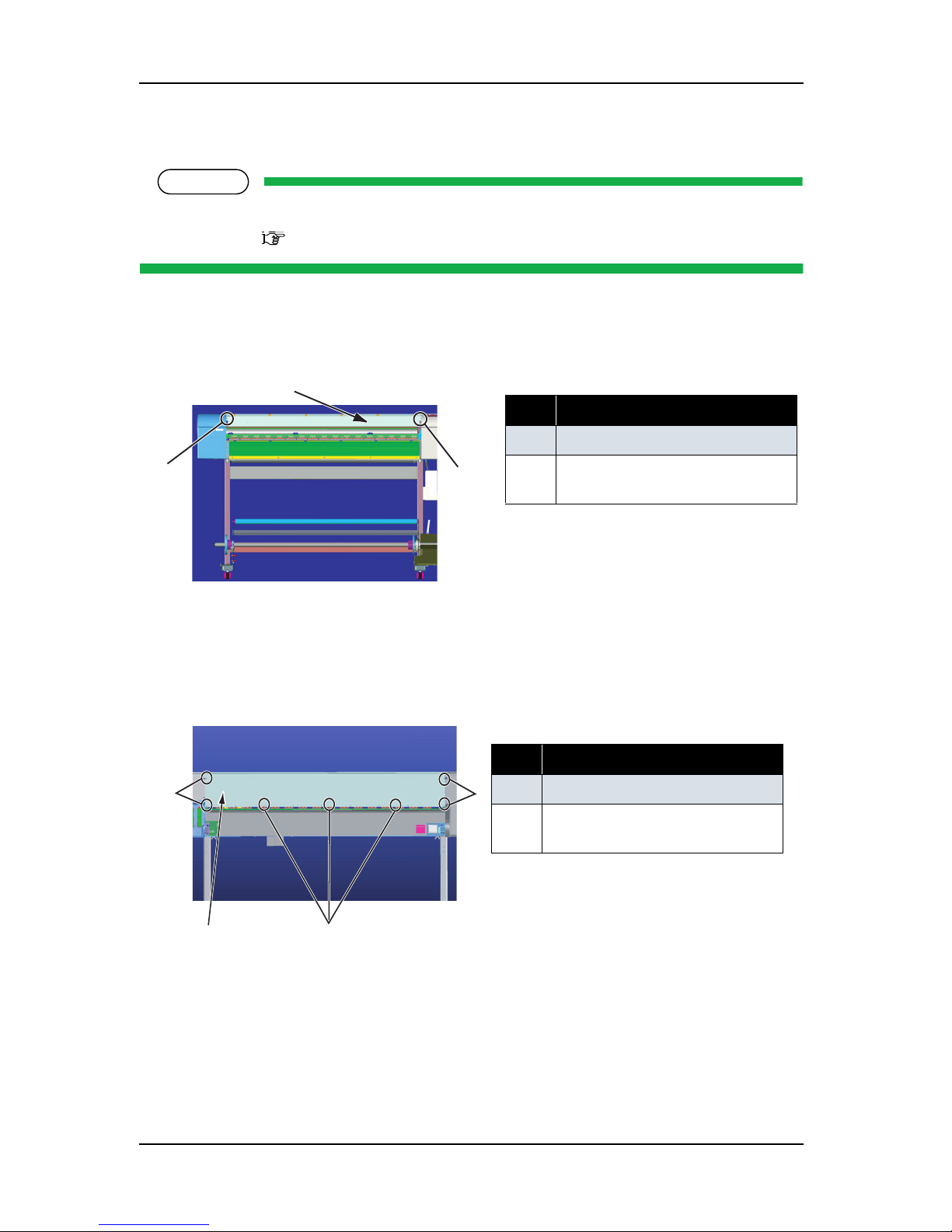
ValueJet 1304 Service manual
AP-74109 Rev 1.1 4-16
4.2.6 Removing Top Cover
NOTE
Before removing the top cover, remove the following parts.
• Front cover: "4.2.5 Removing Front Cover" p.4-14
1. Remove the top cover front side-retaining screw (round head spring screw M3 × 5: 2).
2. Remove the top cover rear side-retaining screw (round head spring screw M3 × 5: 7).
3. Remove the top cover.
4. Replace the parts inside the product.
5. To reassemble the unit, reverse the removal procedure.
表 4-11
No. Part name
1 Top cover
2 Top cover front side screw
(round head spring screw M3
× 5)
表 4-12
No. Part name
1 Top cover
2
Top cover rear side screw
(round head spring screw M3
× 5)
2
1
2
2
2
1
2
Page 63

ValueJet 1304 Service manual
4-17 AP-74109 Rev 1.1
4.2.7 Removing Media Guide F
1. Remove the media guide F lower-side screw (cup screw M3 × 6 Ni-3bk: 10).
2. Remove the media guide F top screw (platen-retaining screw NX: 4, cup screw M3 × 6 Ni-3bk: 1) and
media guide F right cover and left cover screw (cup screw M3
× 6 Ni-3bk: 6).
3. Remove the media guide F. In the removing process, remove the after-heater AFT_H cable assembly
inside the media guide F, and after-thermistor AFT_T cable assembly.
4. To reassemble the unit, reverse the removal procedure.
NOTE
The spacers are attached to the media guide F top screws except the center one. When fasten the
screws, attach the spacers.
表 4-13
No. Part name
1 Media guide F
2
Media guide F screw
(cup screw M3
× 6 Ni-3bk)
表 4-14
No. Part name
1 Media guide F
2
Media guide F top screw
(platen-retaining screw NX)
3 Media guide F right cover and left
cover screw
(cup screw M3
× 6 Ni-3bk)
2
2
1
2
3
3
1
3
22
Page 64
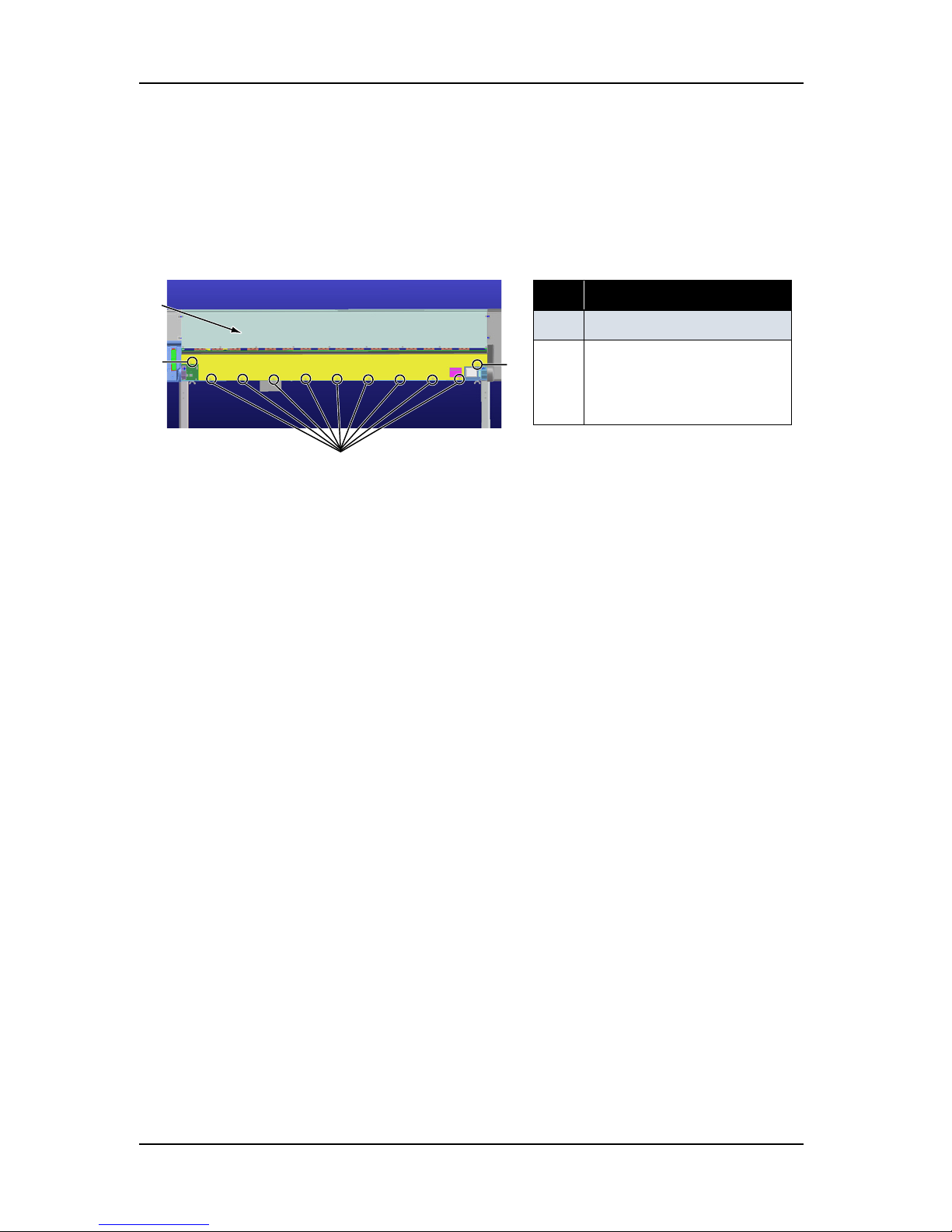
ValueJet 1304 Service manual
AP-74109 Rev 1.1 4-18
4.2.8 Removing Media Guide R2
1. Remove the media guide R2-retaining screw (tapping screw M3 × 6, S tight cup: 11). The number of
screws varies depending on models.
2. Remove the media guide R2 by pulling it backward.
3. Replace the parts inside the product.
4. To reassemble the unit, reverse the removal procedure.
表 4-15
No. Part name
1 Rear cover
2
Media guide R2-retaining
screw
(tapping screw M3
× 6, S tight
cup)
1
2
2
2
Page 65

ValueJet 1304 Service manual
4-19 AP-74109 Rev 1.1
4.2.9 Removing Scroller Receiver (L, R)
1. Remove the scroller receiver L-retaining screw (tapping screw M3 × 6, S tight cup: 2).
2. Remove the scroller receiver L.
3. Remove the scroller receiver L-retaining screw (tapping screw M3
× 6, S tight cup: 2).
4. Remove the scroller receiver R.
5. To reassemble the unit, reverse the removal procedure.
表 4-16
No. Part name
1 Scroller receiver L screw
(tapping screw M3
× 6, S tight
cup)
2
Scroller receiver L
表 4-17
No. Part name
1 Scroller receiver R screw
(tapping screw M3
× 6, S tight
cup)
2
Scroller receiver R
1
2
1
2
Page 66

ValueJet 1304 Service manual
AP-74109 Rev 1.1 4-20
NOTE
There are two hole to attach the scroller receiver on the frame side. See the right of illustration below
for the hole for VJ-1304. Make sure that the part is attached to the appropriate position.
No. Part name
1
Attachment hole for scroller receiver of VJ-1304
2
Screw holes for fixing scroller receiver
1
2
Page 67
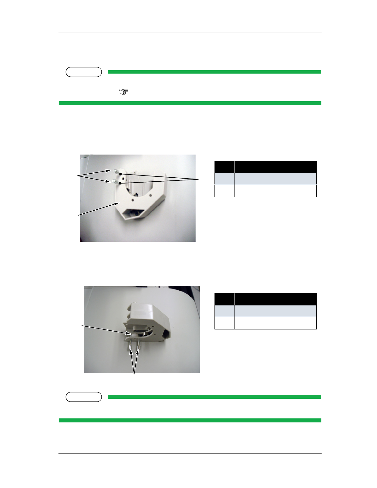
ValueJet 1304 Service manual
4-21 AP-74109 Rev 1.1
4.2.10 Assembling of Scroller Receiver L and R
NOTE
Before assembling scroller receiver, remove the following part.
• Scroller receiver:
"4.2.9 Removing Scroller Receiver (L, R)" p.4-18
1. Attach the two position adjustment scroller roller shafts to the part A shown below of scroller receiver L
(or R). Make sure that the attachment direction is the same in the figure below.
2. Put the scroller receiver roller on the scroller roller shafts R.
NOTE
Scroller roller shaft R is easy-to-fall. Do not let the shaft fall by pressing or slanting it with a finger.
表 4-18
No. Part name
1 Scroller roller shaft R
2
Scroller receiver L
表 4-19
No. Part name
1 Scroller receiver roller
2
Scroller roller shaft R
A
1
2
1
2
Page 68
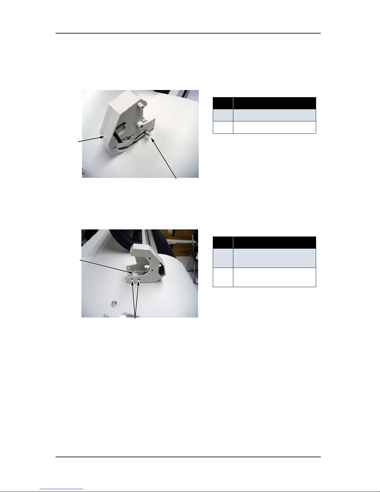
ValueJet 1304 Service manual
AP-74109 Rev 1.1 4-22
3. From the other side of scroller receiver L (or R) explained in step 1 and 2, insert the scroller receiver R
and fix the scroll receiver roller set in step 2.
4. Remove the position adjustment scroller roller shaft R set in step 1.
表 4-20
No. Part name
1 Scroller roller shaft R
2
Scroller receiver L
表 4-21
No. Part name
1 Remove the scroller roller
shaft R in this position.
2
Attached scroller receiver
roller
1
2
1
2
Page 69

ValueJet 1304 Service manual
4-23 AP-74109 Rev 1.1
5. Set the scroller receiver roller to the position B and C in the figure below. Make sure that the rollers are
set on the appropriate position of the scroller receiver R (or L).
6. From the other side of the scroller receiver R (or L) as shown below, insert the scroller roller shaft R and
fix the scroller receiver roller.
7. To reassemble the unit, reverse the removal procedure.
表 4-22
No. Part name
1 Scroller receiver rollers
2
Scroller receiver R
表 4-23
No. Part name
1 Scroller roller shaft R
2
Scroller receiver R
1
2
BC
1
2
Page 70
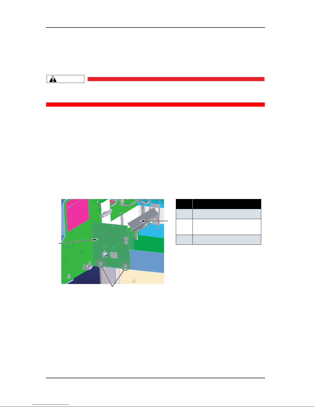
ValueJet 1304 Service manual
AP-74109 Rev 1.1 4-24
4.3 Replacement of Board Base Section Components
This section describes replacement procedures of power board assembly, main board assembly, and cooling
fan.
CAUTION
When you handle a circuit board, do not touch any elements on it with bare hands.
Doing so may cause electrostatic discharge and damage the elements.
4.3.1 Removing Connector Panel and Cooling Fan
(1) Removing Connector Panel
1. Remove the cooling fan (5V) cable from the clamp.
2. Remove the cooling fan (5V) connector.
3. Remove the connector panel screw (tapping screw M3
× 6, S cup: 2).
4. Remove the connector panel.
表 4-24
No. Part name
1 Connector panel
2
Connector panel screw
(tapping screw M3
× 6, S cup)
3 Cooling fan (5V)
2
1
3
Page 71
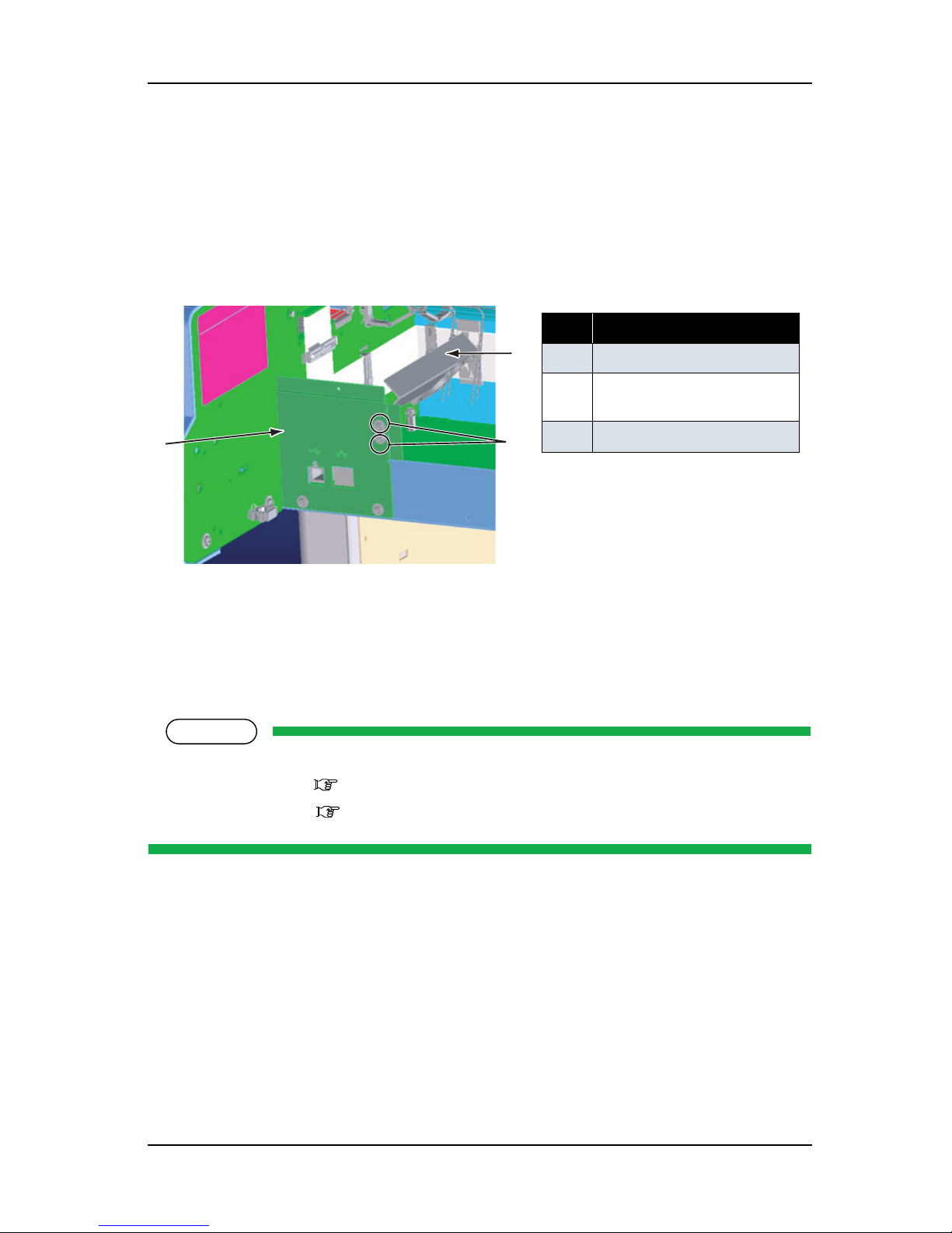
ValueJet 1304 Service manual
4-25 AP-74109 Rev 1.1
(2) Replacing Cooling Fan (5V)
1. Remove the cooling fan (5V) cable from the clamp.
2. Remove the cooling fan (5V) connector.
3. Remove the fan bracket screw (tapping screw M3
× 6, S cup: 2).
4. Remove the cooling fan screw (round head spring screw M3 × 20: 2) from the fan bracket.
5. Replace the cooling fan.
4.3.2 Removing Main Board Bracket
NOTE
Before replacing the board assemblies, remove the following parts.
• Media guide R2: "4.2.8 Removing Media Guide R2" p.4-17
• Connector panel: "4.3.1 Removing Connector Panel and Cooling Fan" p.4-23
1. Remove the following connectors from the main board assembly.
表 4-25
No. Part name
1 Connector panel
2
Fan bracket screw
(tapping screw M3
× 6, S cup)
3
Cooling fan (5V)
3
2
Page 72

ValueJet 1304 Service manual
AP-74109 Rev 1.1 4-26
CAUTION
• Before replacing board or connecting/removing tape wire (FFC), unplug the power cable
and leave the printer for a while. Or board may be damaged by overcurrent.
• When connecting or removing the FFC type cables to the main board assembly
connector, always pull or push the cables perpendicularly to the connector.
Pulling or pushing the wire slantwise may damage/short/break the terminals in the
connectors, resulting in a breakdown of the on-board elements.
• You can connect/remove the tape wire up to five times.
Page 73

ValueJet 1304 Service manual
4-27 AP-74109 Rev 1.1
Table 4-26 Connectors to Main Board Assembly
No. Connector
No.
# of pins Color Connect to Remarks
1 J1 14 White Power board assembly Connected to CN301 by using
DC cable assembly.
2 J5 FFC Black Operation panel unit assembly
3 J9 FFC Black CR board assembly J203 Connected to J203 by using CR
tape wire.
4 J10 FFC Black CR board assembly Connected to J202 by using CR
tape wire.
5 J11 FFC Black CR board assembly Connected to J201 by using CR
tape wire.
6 J12 4 White PF ENC assembly -
7 J14 - - Unused -
8 J15 - - Unused -
9 J16 - - Unused -
10 J17 - - Unused -
11 J20 2 White PF motor assembly -
12 J21 3 White CR motor assembly -
13 J22 4 White Pump motor assembly -
14 J23 - - Unused -
15 J24 3 White CR_ORG sensor -
16 J25 2 White Suction fan 1 assembly -
17 J26 2 Black Suction fan 2 assembly
-
18 J27 3 Black Wiper origin sensor -
19 J28 2 Red Suction fan 3 assembly
-
20 J29 2 Yellow Suction fan 4 assembly -
21 J30 3 Blue Lever sensor assembly -
22 J28 2 White Cooling fan (5V) assembly -
23 J29 3 Red Waste fluid level switch (VJ16) -
24 J36 2 Red Cooling fan (24V) assembly -
25 J38 3 Yellow Cover R sensor -
26 J40 4 Blue Cover L sensor -
27 J41 - - Unused -
28 J42 4 Black P_REAR sensor -
29 J43 8 - HEATER CONT board -
30 J45 - - Unused -
Page 74

ValueJet 1304 Service manual
AP-74109 Rev 1.1 4-28
2. Remove the cable from the three clamps on the main board bracket.
3. Remove the following parts (if needed);
a. AC cable between terminal block and Main board assembly
b. DC cable between Main board assembly and CNT
c. Serial cable assembly between Main board assembly and CNT
31 J46 4 Natural
color
HEATER CONT board -
Table 4-26 Connectors to Main Board Assembly (Continued)
No. Connector
No.
# of pins Color Connect to Remarks
SODIMM 128MB
J17
J15
J4
J43
J16
J2
J8
J7
J41
J3
J12
J5
J44
J40
J14
KINK
MINK
DEBUG
SERIALREV
CINK
YINK
SYSTEM
FPGAJTAG
COVERL
PFENC
PANEL
ispJTAG
J32
J34
J36J42
PREAR
SENS
CFAN1
CFAN2
CFAN3(+24V)
isp-CLK-JTAG
J24
J30
J38
J39
J37
J35
J33
J27
CRORG
WSENSEL
WSENSER
REVSENS1
REVSENS2
OPTIONIF
WIPEORG
LEVERSENS
COVERR
J18
J19
REVINK1
REVINK2
TOCRJ201
TOCRJ202
TOCRJ203
J11
J10
J9
USBIF
J6
ETHER
NET
J20
PF
MOTOR
CR
MOTOR
J21
J22
PUMP1
J23
PUMP2
J26
BLOWER
FAN2
BLOWER
FAN1
J25
J29
BLOWER
FAN4
J46
BLOWER
FAN3
J28
J1
MAINboardassembly
Page 75
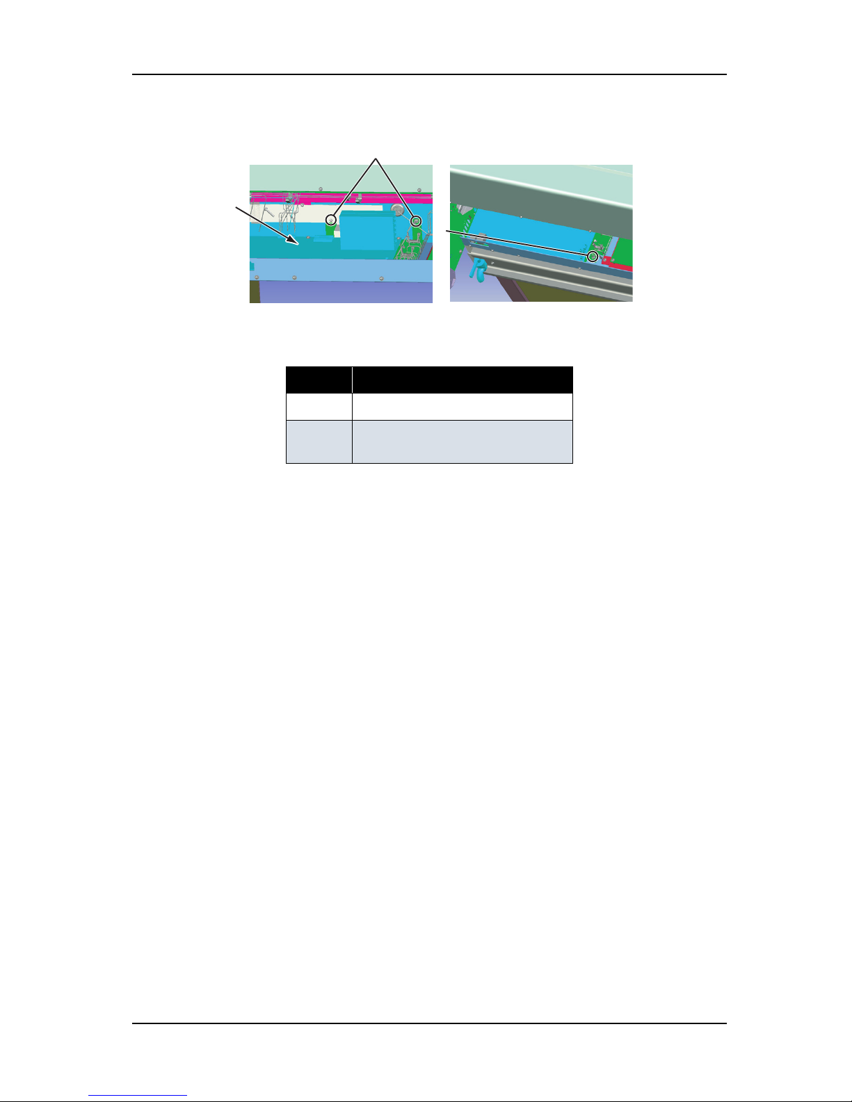
ValueJet 1304 Service manual
4-29 AP-74109 Rev 1.1
4. Remove the board bracket-retaining screws (tapping screw M3 × 6, S tight cup: 5).
5. Slide the main board bracket to the right then lift from the front side and remove it.
表 4-27
No. Part name
1 Main board bracket
2 Main board bracket-retaining screw
(tapping screw M3
× 6, S tight cup)
1
2
2
Page 76
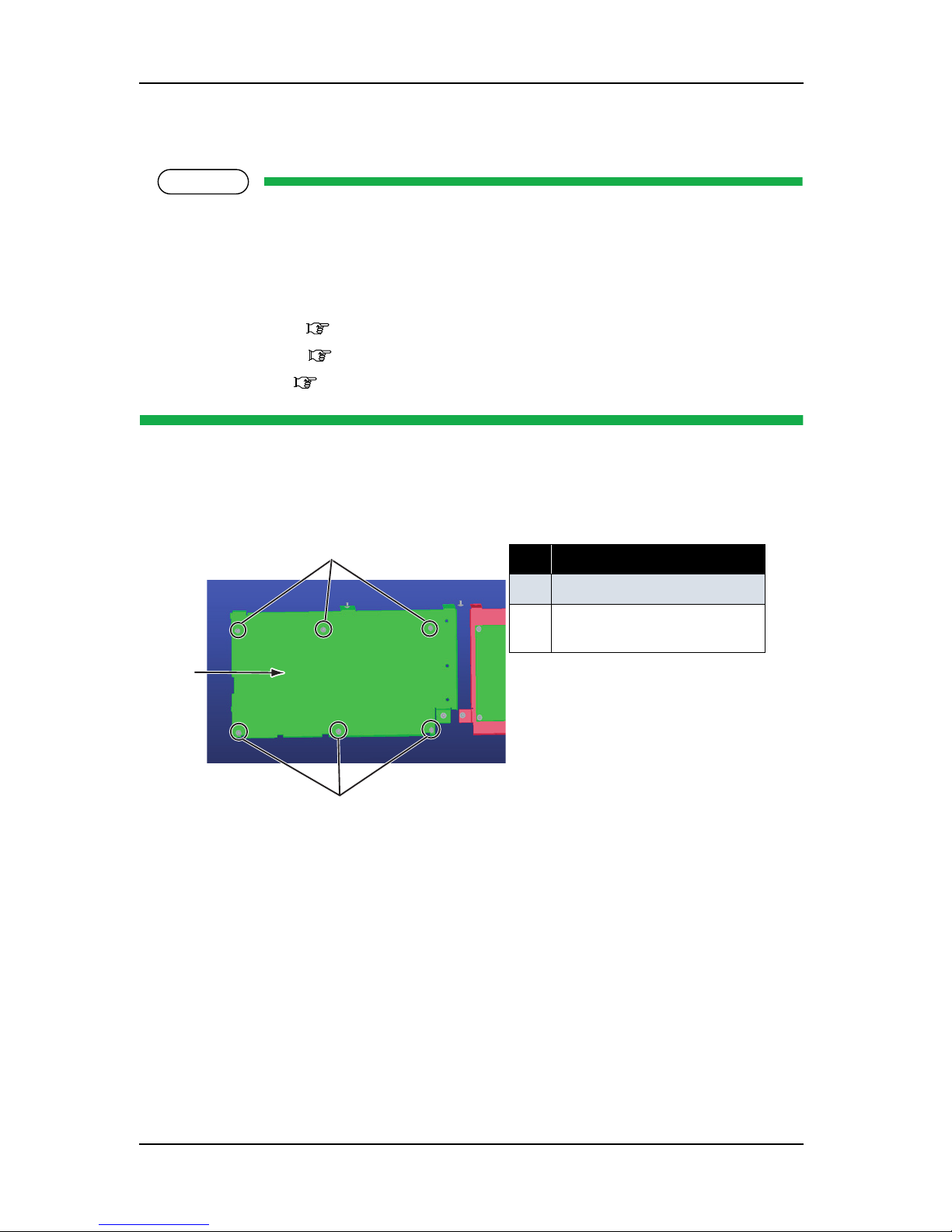
ValueJet 1304 Service manual
AP-74109 Rev 1.1 4-30
4.3.3 Replacing Main Board Assembly
NOTE
• When replacing the main board assembly, make sure to back up the parameters by following the
instructions in "7.3.1 Parameter Backup" p.7-12. Otherwise, the life counters on the waste fluid
box or the tube cannot be updated and ink may overflow inside the machine.
Perform other adjustments by following the instructions in "7.2 Adjustment Item" p.7-3.
• Before replacing the main board assembly, remove the following parts.
• Media guide R2: "4.2.8 Removing Media Guide R2" p.4-17
• Connector panel: "4.3.1 Removing Connector Panel and Cooling Fan" p.4-23
• Board bracket: "4.3.2 Removing Main Board Bracket" p.4-24
1. Remove the screws retaining the main board assembly to the board bracket (cup screw M3 × 6: 7)
.
2. Replace the main board assembly
3. To reassemble the unit, reverse the removal procedure.
4. Install the parameters and firmware by following the instructions in "7.3 Working with MUTOH
Maintenance Engineer Assistant" p.7-8 and "7.4 Working with MUTOH Service Assistance" p.7-
30.
5. Perform adjustment on media edge sensor and the P_REAR sensor by following the instructions in "7.2
Adjustment Item" p.7-3.
表 4-28
No. Part name
1 Main board assembly
2
Main board assembly screw
(cup screw M3
× 6)
1
2
2
Page 77

ValueJet 1304 Service manual
4-31 AP-74109 Rev 1.1
4.3.4 Replacing HEATER CONT board assembly
1. Remove the cable from the five brackets at the top of the HEATER CONT board assembly.
2. Remove the following connectors from the HEATER CONT board assembly.
表 4-29
No. Part name
1 Board bracket
2 Clamp
Table 4-30 Connectors to HEATER CONT board assembly
No. Connector
No.
# of
pins
Color Connect to Remarks
1 J2 - - - Unused
2 J3 - - - Unused
3 J4 - - - Unused
4 J5 - - - Unused
5 J6 FFC - HEATER RELAY board
6 J7 - - - Not equipped
7 J8 4 White HEATER JUNCTION board Connected to J2 by using power
cable assembly between CNT JC.
8 J9 Serial - HEATER JUNCTION board Connected to J3 by using serial
cable assembly between MAIN
- CNT.
9 J10 Serial - Main board assembly Connected to assembly J43 by
using serial cable between
MAIN - CNT.
10 J11 - - - Unused
2
2
1
Page 78

ValueJet 1304 Service manual
AP-74109 Rev 1.1 4-32
3. Replace the following parts;
AC cable assembly between CNT - RLY
Tape wire between CNT - RLY
DC cable assembly between MAIN - CNT
Serial cable between MAIN - CNT
AC cable between CNT - Power unit
DC cable between CNT - Power unit
11 J12 - - - Unused
12 J13 - - - Unused
13 J14 - - - Unused
14 J15 - - - Unused
15 J16 - - - Unused
16 J17 - - - Unused
17 J18
- - - Unused
18 J19 8 White Main board assembly Connected to J46 by using
power cable assembly between
MAIN - CNT.
19 J20 - -
- Unused
20 J21 - - - Unused
21 J22 2 White Terminal block AC cable between terminal
block and CNT
22 J23 2 White HEATER RELAY AC cable assembly between
CNT - RLY
Table 4-30 Connectors to HEATER CONT board assembly (Continued)
No. Connector
No.
# of
pins
Color Connect to Remarks
Page 79

ValueJet 1304 Service manual
4-33 AP-74109 Rev 1.1
4. Remove the HEATER CONT board bracket-retaining screw (tapping screw M3 × 6, S tight cup: 4), and
remove it.
5. Remove the HEATER CONT board-retaining screw (cup screw M3 × 6 white: 9).
6. Replace the HEATER CONT board assembly.
7. To reassemble the unit, reverse the removal procedure.
8. Install the firmware for the HEATER CONT board following the instruction in "7.3.7 Sub Controller
Installation" p.7-29.
表 4-31
No. Part name
1 HEATER CONT board bracket
2 HEATER CONT board bracket-retaining screw
(tapping screw M3
× 6, S tight cup)
表 4-32
No. Part name
1 HEATER CONT board
assembly
2
HEATER CONT board
assembly screw
(cup screw M3
× 6 white)
2
2
1
1
2
2
Page 80
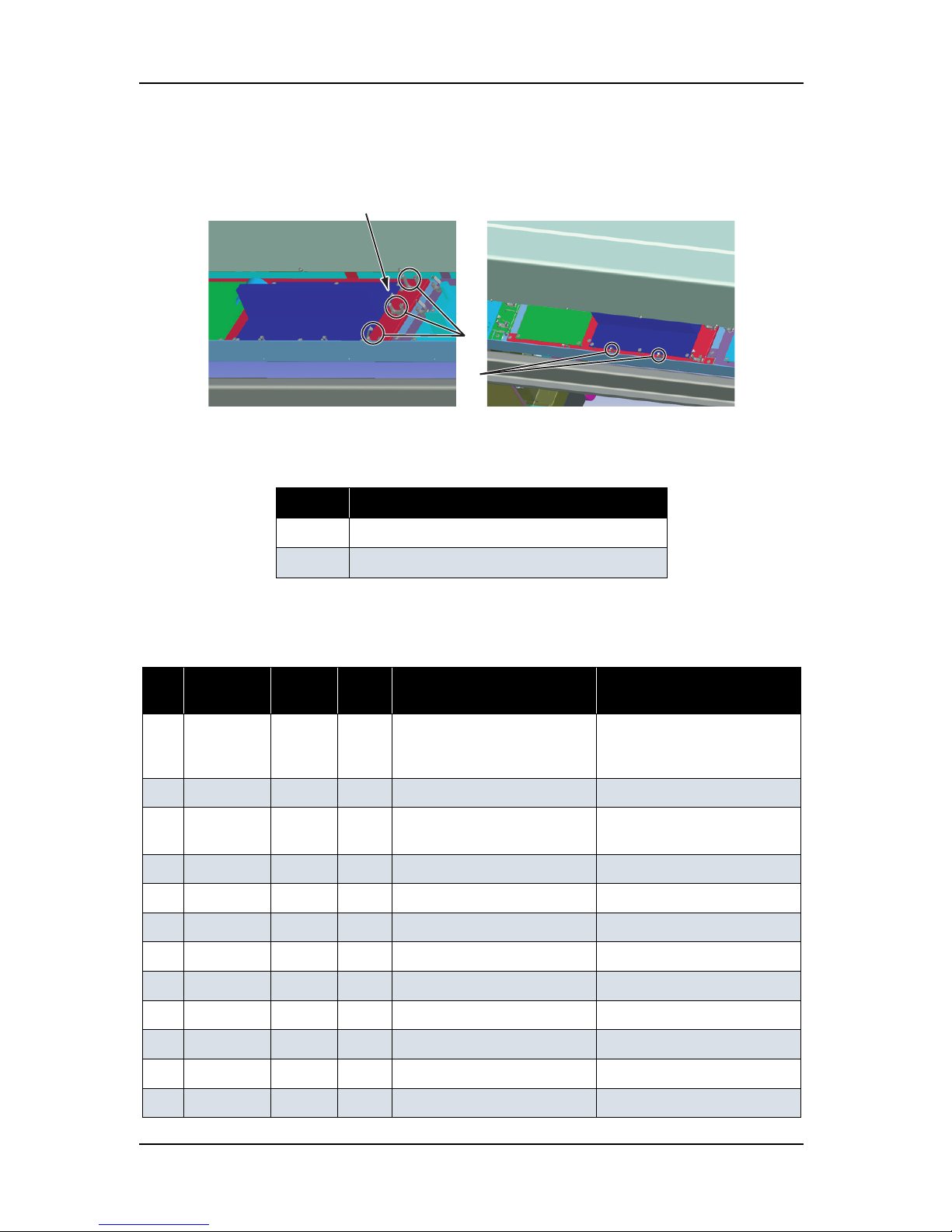
ValueJet 1304 Service manual
AP-74109 Rev 1.1 4-34
4.3.5 Replacing HEATER RELAY board assembly
1. Remove the cable from the five clamps on the top of HEATER CONT board bracket.
2. Remove the following connectors from the HEATER RELAY board assembly.
表 4-33
No. Part name
1 HEATER CONT board bracket
2 Clamp
Table 4-34 Connectors to HEATER RELAY board assembly
No. Connector
No.
# of
pins
Color Connect to Remarks
1 J1 2 White HEATER CONT board Connected to J23 by using AC
cable assembly between CNT RLY.
2 J2 7 White Platen heater 1
3 J3 FFC - HEATER CONT board
assembly
Connected to J6 by using tape
wire between CNT - RLY.
4 J4 2 White AC-IN
5 J5 7 White Platen heater
6 J6 2 White AC-OUT
7 J7 3 White Pre-heater 1
8 J8 3 White Pre-heater 2
9 J9 4 White After-heater
10 J10 2 Blue Cooling fan
11 J12 2 White Platen thermistor 1
12 J13 2 Black Platen thermistor 2
2
2
1
Page 81

ValueJet 1304 Service manual
4-35 AP-74109 Rev 1.1
3. Replace the AC cable assembly between CNT-RLY, and RLY_AC cable assembly.
4. Remove the HEATER CONT board bracket-retaining screws (tapping screw M3
× 6 tight cup: 4), and
remove the board bracket.
13 J15 2 Red Pre-thermistor
14 J17 3 White After-thermistor
表 4-35
No. Part name
1 HEATER CONT board bracket
2 HEATER CONT board bracket-retaining screw
(tapping screw M3
× 6 tight cup: 4)
Table 4-34 Connectors to HEATER RELAY board assembly
No. Connector
No.
# of
pins
Color Connect to Remarks
2
2
1
Page 82

ValueJet 1304 Service manual
AP-74109 Rev 1.1 4-36
5. Remove the relay board assembly retaining screws (cup screw M3 × 6 white: 9).
6. Replace the relay board assembly.
7. To reassemble the unit, reverse the removal procedure.
4.3.6 Replacing Power Board Assembly
CAUTION
• When removing the power board assembly, remove the power cable and wait for at least
5 minutes before taking it out; this will discharge the residual electrical charge of the
electrolytic capacitor.
If you handle these boards before the capacitor charge is fully discharged, you may suffer
electric shock.
• To avoid electric shock, never touch the back of the power board.When handling the
power board, take the side of the board.
• To avoid a short circuit, do not place the power board assembly directly on conductive
objects.
NOTE
Before replacing the power board assembly, remove the following parts.
• Rear cover: "4.2.8 Removing Media Guide R2" p.4-17
• Connector panel: "4.3.1 Removing Connector Panel and Cooling Fan" p.4-23
表 4-36
No. Part name
1 Relay board assembly
2
Relay board assembly screw
(cup screw M3
× 6 white)
1
2
2
Page 83
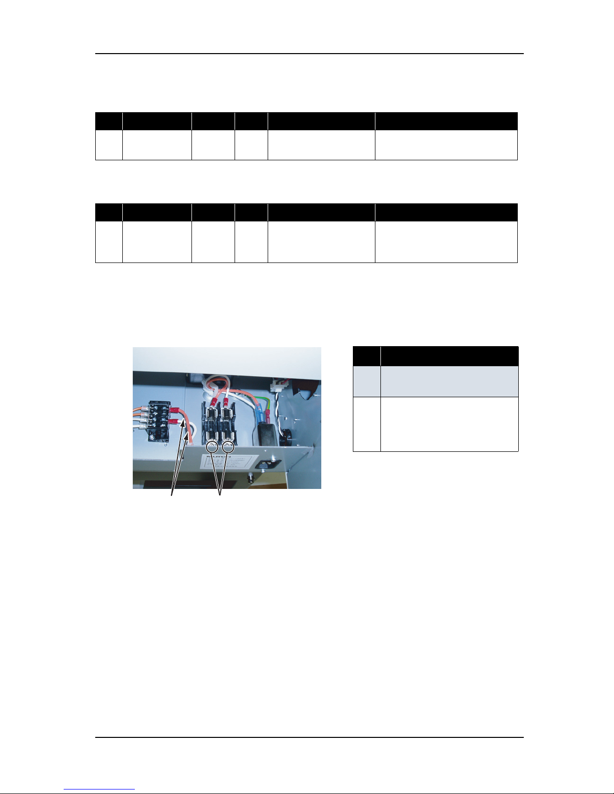
ValueJet 1304 Service manual
4-37 AP-74109 Rev 1.1
1. Remove the following connector from the power board assembly.
2. Remove the following connector from the HEATER-CONT board.
3. Remove the fuse-side two screws (pan head small screw M4 × 6) retaining Fuse to terminal block AC
cable assembly, and remove the assembly.
Table 4-37 Connectors to Power Board Assembly
No. Connector No. # of pins Color Connect to Remarks
1 CN301 - White Main board assembly Connected to J1 by using DC cable
assembly.
Table 4-38 Connectors to HEATER-CONT Board Assembly
No. Connector No. # of pins Color Connect to Remarks
1 J22 - White Terminal Connected to terminal block by
using Terminal block to CNT AC
cable assembly
表 4-39
No. Part name
1 Fuse to terminal block AC cable
assembly
2
Screws retaining Fuse to
terminal block AC cable
assembly to fuse holder
(pan head small screw M4
× 6)
2
1
Page 84

ValueJet 1304 Service manual
AP-74109 Rev 1.1 4-38
4. Remove the three cables from clamp of the front side of HEATER-RELAY board bracket.
5. Remove the power board bracket-retaining screw (tapping screw M3
× 6 S tight cup).
表 4-40
No. Part name
1 HEATER-RELAY board
bracket
2
Clamp
表 4-41
No. Part name
1 Power board bracket
2 Screw retaining power board bracket
2
1
1
1
2
2
Page 85
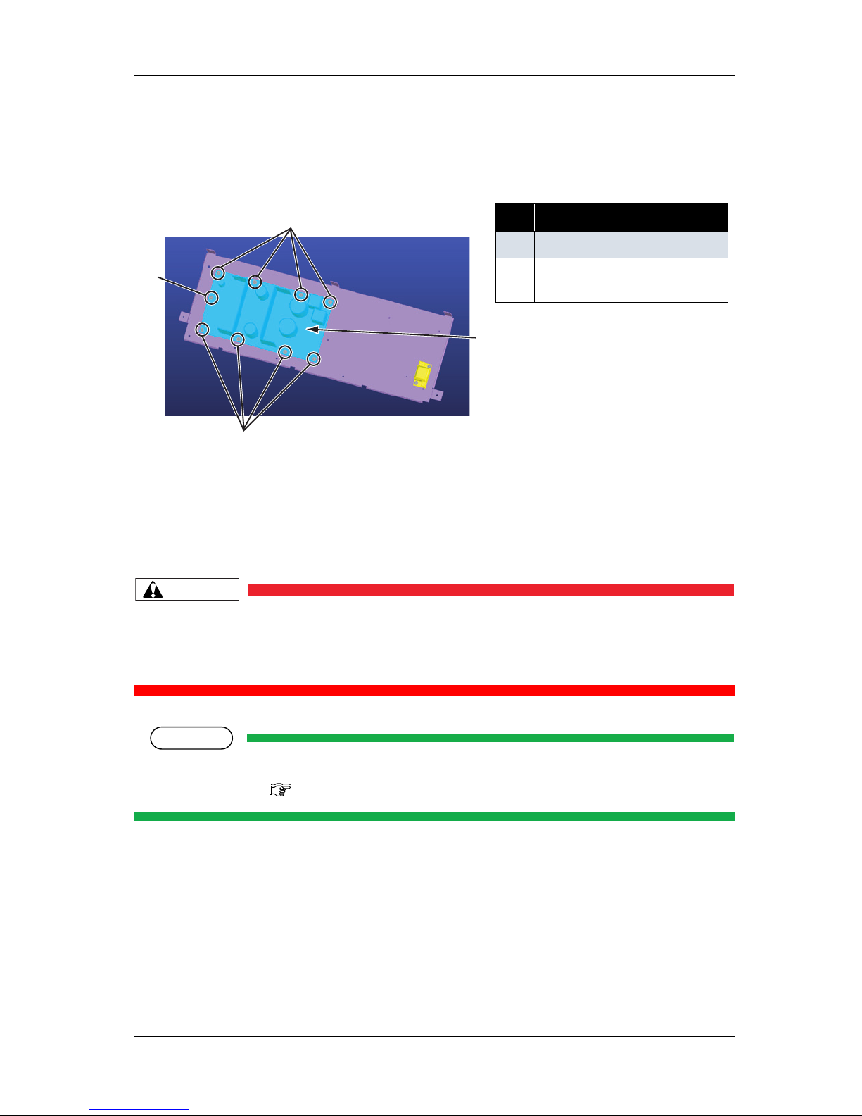
ValueJet 1304 Service manual
4-39 AP-74109 Rev 1.1
6. Remove the power board assembly-retaining screw (cup screw M3 × 6 white: 9).
7. Replace the power board assembly.
8. To reassemble the unit, reverse the removal procedure.
4.3.7 Replacing Fuse
CAUTION
Use the Fuse which specification matches as follows.
• Specification: 250V 15A, φ10.31mm
× 38.1mm
• Double pole/ Neutral Fusing
NOTE
Before replacing fuse, remove the following parts.
• Media guide R2:
"4.2.8 Removing Media Guide R2" p.4-17
表 4-42
No. Part name
1 Power board assembly
2
Power board screw
(cup screw M3
× 6 white)
1
2
2
2
Page 86
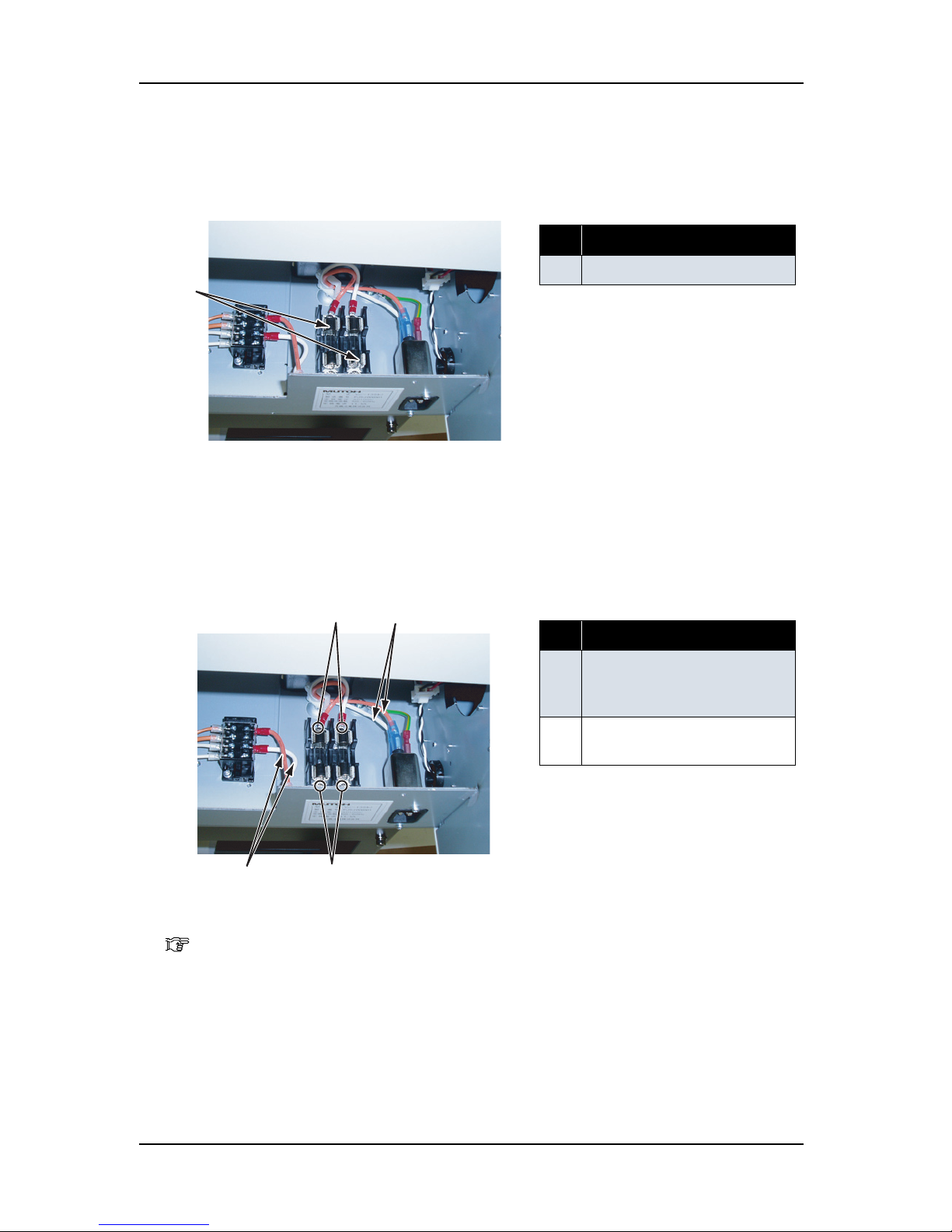
ValueJet 1304 Service manual
AP-74109 Rev 1.1 4-40
1. Pick up the fuse using a finger on the center of the part and remove it.
2. Replace the fuse.
3. Remove the two screws (pan head small screw M4
× 6) retaining the noise filter to fuse AC cable
assembly and fuse to terminal block AC cable assembly.
4. Remove the AC inlet.
"4.3.8 Replacing Inlet Assembly" p.4-41
5. Remove the noise filter to fuse AC cable assembly from AC inlet.
6. Replace the assembly.
表 4-43
No. Part name
1 Fuse
表 4-44
No. Part name
1 Screws retaining the fuse to
terminal block AC cable
assembly
2
Fuse to terminal block AC cable
assembly
1
2
1
1
2
Page 87

ValueJet 1304 Service manual
4-41 AP-74109 Rev 1.1
7. Remove the protect cover on the top of terminal block, then remove the screws retaining the fuse to
terminal block AC cable assembly to terminal block.
8. Replace the fuse to terminal block AC cable assembly.
9. To reassemble the unit, reverse the removal procedure.
表 4-45
No. Part name
1 Protect cover of terminal block
2
Screws retaining the fuse to
terminal block AC cable
assembly
1
2
Page 88

ValueJet 1304 Service manual
AP-74109 Rev 1.1 4-42
4.3.8 Replacing Inlet Assembly
NOTE
Before replacing the inlet assembly, remove the following parts.
• Media guide R2: "4.2.8 Removing Media Guide R2" p.4-17
(1) Removing Cooling Fan (24V)
1. Remove the screw retaining the cooling fan (24V) (pan head small screw M 4 × 30: 2).
2. Remove the cooling fan (24V) cable connector.
3. Replace the cooling fan.
4. To reassemble the unit, reverse the removal procedure.
表 4-46
No. Part name
1 Cooling fan (24V) screw
(pan head small screw M 4
×
30)
2
Cooling fan (24V)
表 4-47
No. Part name
1 Cooling fan (24V) connector
1
2
1
Page 89

ValueJet 1304 Service manual
4-43 AP-74109 Rev 1.1
TIP
• When reassembling the cooling fan, spread the fan seal (shown in the diagram below) under the
fan, then screw the fan on it
• Installation direction of the cooling fan assembly (sealing surface and cable pulling direction) is
specified. Install it with the sealing surface facing up.
表 4-48
No. Part name
1 Fan seal
1
Page 90

ValueJet 1304 Service manual
AP-74109 Rev 1.1 4-44
(2) Replacing Inlet Assembly
1. Remove the inlet assembly-retaining screws (round head spring screw (finishing) M3 × 10: 2).
.
2. Remove the connectors from the inlet assembly.
3. Remove the Inlet fixing board.
.
4. Replace the inlet assembly
5. To reassemble the unit, reverse the removal procedure.
TIP
When installing the inlet assembly, match the corresponding color connectors.
表 4-49
No. Part name
1 Inlet assembly connector
2 Inlet assembly
3 Inlet assembly screw
(round head spring screw
(finishing) M3
× 10)
表 4-50
No. Part name
1 Inlet assembly
2 Inlet fixing board
1
2
3
1
2
Page 91

ValueJet 1304 Service manual
4-45 AP-74109 Rev 1.1
4.4 Replacement of PF Driving Section Components
4.4.1 Replacing PF Motor Assembly
NOTE
Before replacing parts in the PF motor assembly, remove the following covers.
•L side cover: "4.2.3 Removing L Side Cover" p.4-10
• Media guide R2: "4.2.8 Removing Media Guide R2" p.4-17
1. Remove the PF motor assembly connectors out through the PF motor cable assembly.
2. Remove the screw retaining the PF motor to the PF bracket (M4
× 8 round head spring screw: 2).
表 4-51
No. Part name
1 PF motor cable
2
PF motor assembly connector
表 4-52
No. Part name
1 PF bracket:
2
PF motor screw
(round head spring screw M4
×
8)
3 PF speed reduction belt
2
1
1
2
2
Page 92
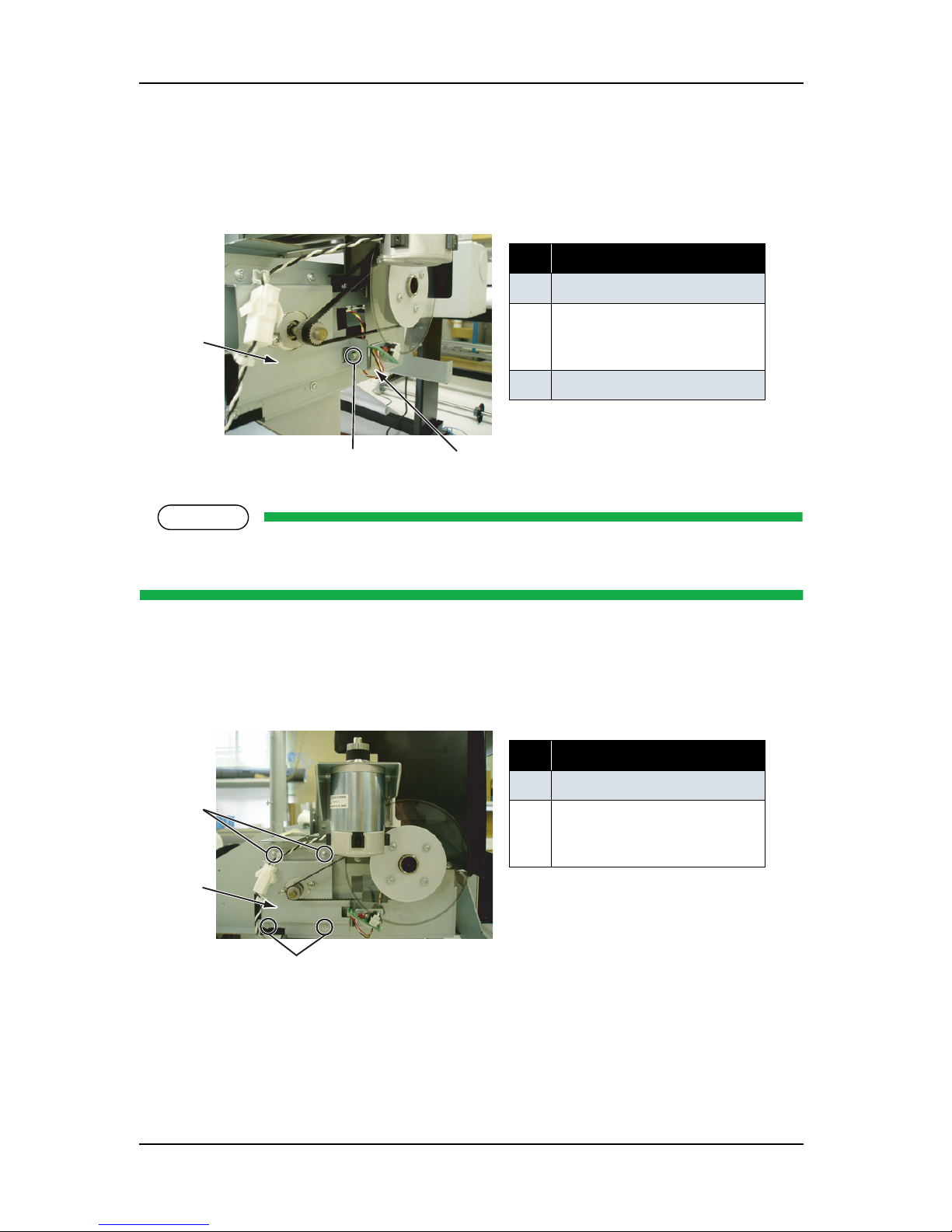
ValueJet 1304 Service manual
AP-74109 Rev 1.1 4-46
3. Remove the screw (round head spring screw M3 × 6: 1) retaining PF encoder fixing board t2 to PF
bracket, then remove the PF encoder fixing board t2.
.
NOTE
When removing PF encoder fixing board t2 from the PF bracket, do not damage the PF scale by
contacting with PF ENC assembly. Also, do not bend or touch the outer circumference of PF scale.
4. Remove the four screws (tapping screw M3 × 6 S tight cup) retaining PF bracket and remove the bracket
with PF motor assembly.
.
5. Remove the screw retaining the PF motor assembly and replace the assembly.
6. To reassemble the unit, reverse the removal procedure.
表 4-53
No. Part name
1 PF bracket
2 Screws retaining PF encoder
fixing board t2 (round head
spring screw m3
× 6)
3 PF encoder fixing board t2
表 4-54
No. Part name
1 PF bracket
2 Screws retaining PF bracket
(tapping screw M3
× 6 S tight
cup)
1
2
3
1
2
2
Page 93

ValueJet 1304 Service manual
4-47 AP-74109 Rev 1.1
NOTE
Move the PF speed reduction pulley with your hand to check if the PF speed reduction belt is equally
balanced on the pulley center section of the PF motor assembly.
7. Perform adjustments by following the instructions in "7.2 Adjustment Item" p.7-3.
Page 94

ValueJet 1304 Service manual
AP-74109 Rev 1.1 4-48
4.4.2 Replacing PF_ENC Assembly
NOTE
Before replacing parts in the PF_ENC assembly, remove the following covers.
•L side cover: "4.2.3 Removing L Side Cover" p.4-10
• Rear cover: "4.2.8 Removing Media Guide R2" p.4-17
1. Remove the PF_ENC assembly connectors from the main board assembly.
"4.3.3 Replacing Main Board Assembly" p.4-29
2. Take the PF_ENC assembly cable off the clamp, then pull it out through the L frame cable inlet.
3. Remove the PF_ENC assembly-retaining screw (tapping screw M2 × 5: 2).
NOTE
Do not damage, bend the PF scale, or touch the outer edge of the scale.
4. Replace the PF_ENC assembly.
5. To reassemble the unit, reverse the removal procedure.
6. Perform adjustments by following the instructions in "7.2 Adjustment Item" p.7-3.
表 4-55
No. Part name
1 PF_ENC assembly screw
(tapping screw M2
× 5)
2
PF_ENC assembly
1
2
Page 95

ValueJet 1304 Service manual
4-49 AP-74109 Rev 1.1
4.4.3 Replacing PF_ENC Scale
NOTE
Before replacing parts in the PF_ENC scale assembly, remove the following parts.
•L side cover: "4.2.3 Removing L Side Cover" p.4-10
1. Remove the ENC holder-retaining screw (tapping screw M3 × 6, P tight cup).
2. Replace the PF scale.
3. To reassemble the unit, reverse the removal procedure.
NOTE
When handling the PF scale, note the following.
• Do not damage or bend the PF scale. Do not touch the peripheral surface of the PF scale.
• Make sure that no double-sided tape remains on the slit mounting flange.
4. Perform adjustments by following the instructions in "7.2 Adjustment Item" p.7-3.
表 4-56
No. Part name
1 ENC holder screw
(tapping screw M3
× 6, P tight
cup)
2
PF_ENC scale
3 ENC holder
2
1
3
1
Page 96

ValueJet 1304 Service manual
AP-74109 Rev 1.1 4-50
4.4.4 Replacing Heater and Thermistor Assembly
(1) Replacing After-heater
1. Remove the media guide F.
"4.2.7 Removing Media Guide F" p.4-16
2. Remove the connectors from both AFT_H relay assembly and AFT_T relay assembly.
3. Remove the after-heater and thermistor.
4. To reassemble the unit, reverse the removal procedure.
NOTE
Wipe the grease away from the heater attachment area before installing it.
(2) Replacing Pre-heater
1. Remove the media guide R2.
"4.2.8 Removing Media Guide R2" p.4-17
2. Remove the connectors for PRE_H relay assembly and PRE_H2 relay assembly.
NOTE
Replace the pre-heater while media guide R1 is attached to the printer.
表 4-57
No. Part name
1 After-heater
2
Thermistor assembly
2
Page 97

ValueJet 1304 Service manual
4-51 AP-74109 Rev 1.1
3. Remove the media guide stay b-retaining screw (cup screw M3 × 6 Ni-3 bk: 5), and remove the media
guide stay b.
4. Remove the pre-heater and thermistor assembly.
5. To reassemble the unit, reverse the removal procedure.
NOTE
Wipe the grease away from the heater attachment area before installing it.
表 4-58
No. Part name
1 Media guide stay b
2
Media guide stay b-retaining
screw (cup screw M3
× 6 Ni-3
bk)
表 4-59
No. Part name
1 Media guide R1
2
Pre-heater
3 Thermistor assembly
Page 98
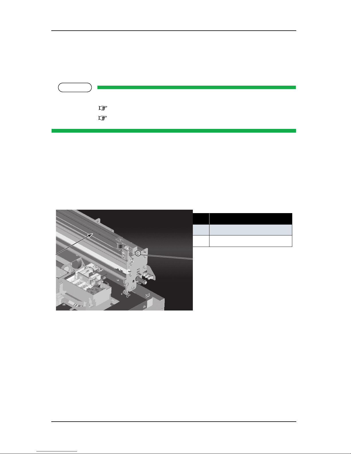
ValueJet 1304 Service manual
AP-74109 Rev 1.1 4-52
4.5 Replacement of CR Driving Section Components
4.5.1 CR Motor Assembly
NOTE
Before replacing parts in the CR motor assembly, remove the following covers.
• R side cover: "4.2.1 Removing R Side Cover" p.4-6
•L side cover: "4.2.3 Removing L Side Cover" p.4-10
1. Detach the CR motor assembly connector from the cable connector.
2. Take the CR motor assembly cable off the clamp.
3. Release the CR locker by pushing it with your finger, then move the carriage from the capping position
to the left.
4. Loosen the CR tension mounting shaft on the R side frame, then release the CR belt tension.
5. Take the CR belt off the CR motor assembly pulley on the L side frame.
表 4-60
No. Part name
1 CR belt
2
CR tension mounting shaft
Page 99

ValueJet 1304 Service manual
4-53 AP-74109 Rev 1.1
6. Remove the screws retaining the CR motor assembly to the CR motor mounting material (cup screw M4
×
8: 4).
7. Replace the CR motor assembly.
8. To reassemble the unit, reverse the removal procedure.
9. Perform adjustments by following the instructions in "7.2 Adjustment Item" p.7-3.
4.5.2 Replacing CR Origin Point Sensor
NOTE
Before replacing parts in the CR_HP sensor assembly, remove the R side cover.
• R side cover: "4.2.1 Removing R Side Cover" p.4-6
1. Release the CR locker by pushing it with your finger, then move the carriage from the capping position
to the left.
表 4-61
No. Part name
1 CR motor mounting
material
2
CR motor screw
(
cup screw M4 × 8
)
3
CR motor
2
1
2
3
Page 100

ValueJet 1304 Service manual
AP-74109 Rev 1.1 4-54
2.
Pull out the CR_HP cable assembly connector from the CR_HP sensor.
3. Release the hook retaining the CR_HP sensor, then remove the CR_HP sensor.
4. Replace the CR_HP sensor.
5. To reassemble the unit, reverse the removal procedure.
6. Perform adjustments by following the instructions in "7.2 Adjustment Item" p.7-3.
表 4-62
No. Part name
1 Hook
2
CR_HP sensor
3
Connector
1
2
3
 Loading...