


Rev No. V5a 2015 Jan
USER MANUAL
Sign Cutting Plotter
Read This Manual Before Using The Plotter.
VC-600
VC-1300
VC-1800

Trademark Mentioned in this Manual
MUTOH, ValueCut, VC-600, VC-1300, VC-1800, ValueJet are registered trademarks or
product names of MUTOH INDUSTRIES LTD.
Other company and product names may be registered trademarks or product names.
Caution
No part of this product or publication may be reproduced, copied, or transmitted in any
form or by any means, except for personal use, without the permission of MUTOH
INDUSTRIES LTD.
The product and the contents of this publication may be changed without prior notification.
MUTOH INDUSTRIES LTD. has made the best efforts to keep this publication free from
error, but if you find any uncertainties or misprints, please call us or the shop where you
bought this equipment.
MUTOH INDUSTRIES LTD. shall not be liable for any damages or troubles resulting from
the use of this equipment or this manual.
ValueCut USER MANUAL Important Information
Important Information
Thank you for purchasing the ValueCut Cutting Plotter.
Before you use the cutting plotter, please make sure that you have read
the safety precautions and instructions below.
Caution
!
SAFETY PRECAUTION
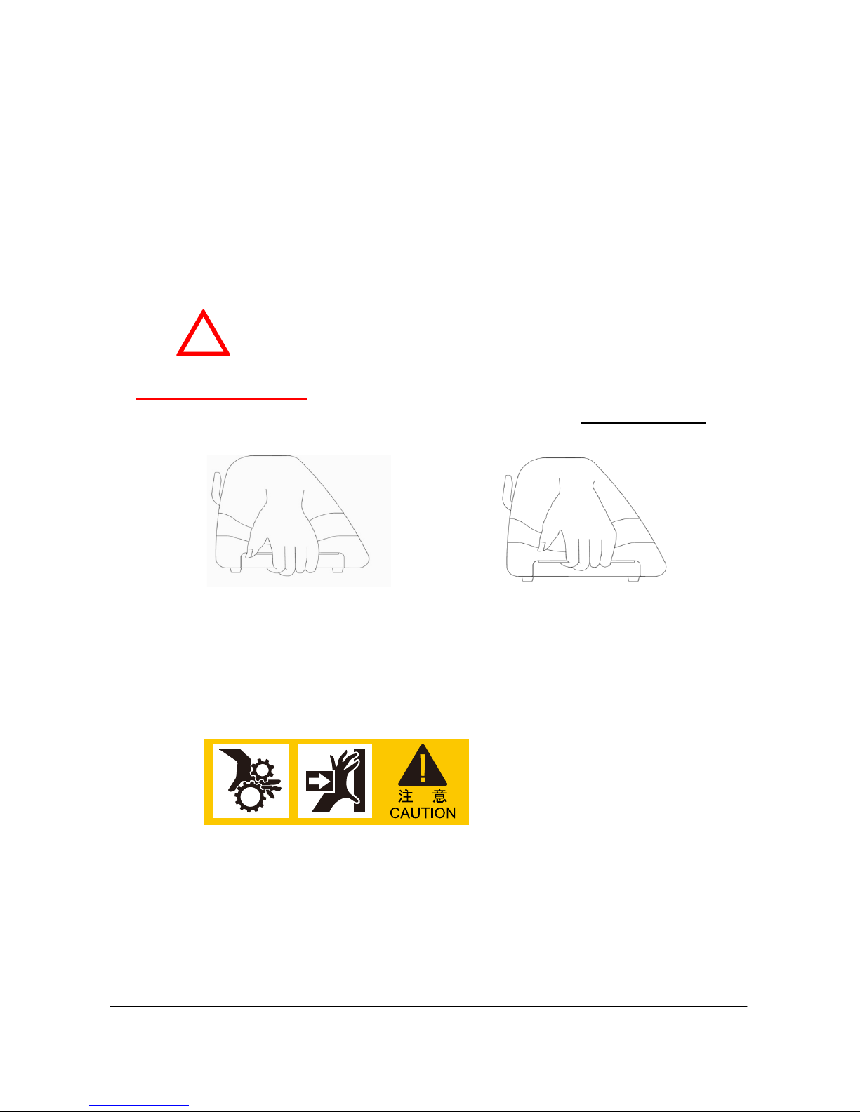
For safety concern, please always hold the cutter firmly from the bottom while
moving it. Do not move the cutter by clasping the depression area on both sides.
Do not place your hand close to the tool carriage to prevent your fingers from
being clamped during the operation of the cutting plotter.
O (Correct) X (Incorrect)
3
V5a 2015 Jan

Important Information ValueCut USER MANUAL
Hazardous moving parts keep fingers and other body parts away!
Do not shake or drop the blade holder, a blade tip can fly out.
During an operation, do not touch any of the moving parts of this machine (such
as the carriage). Also be careful to make sure that clothing and hair do not get
caught.
Always connect the power cable to a grounded outlet.
Always use the accessory power cable which is provided. Do not wire the power
cable so that it becomes bent or caught between objects.
Do not connect the power cable to branching outlet to which other machines are
also connected, or use an extension cable. There is danger of overheating an d of
mis-operation of the machine.
Keep the tools away from children where they can reach.
4
V5a 2015 Jan
ValueCut USER MANUAL Important Information
Operation precaution
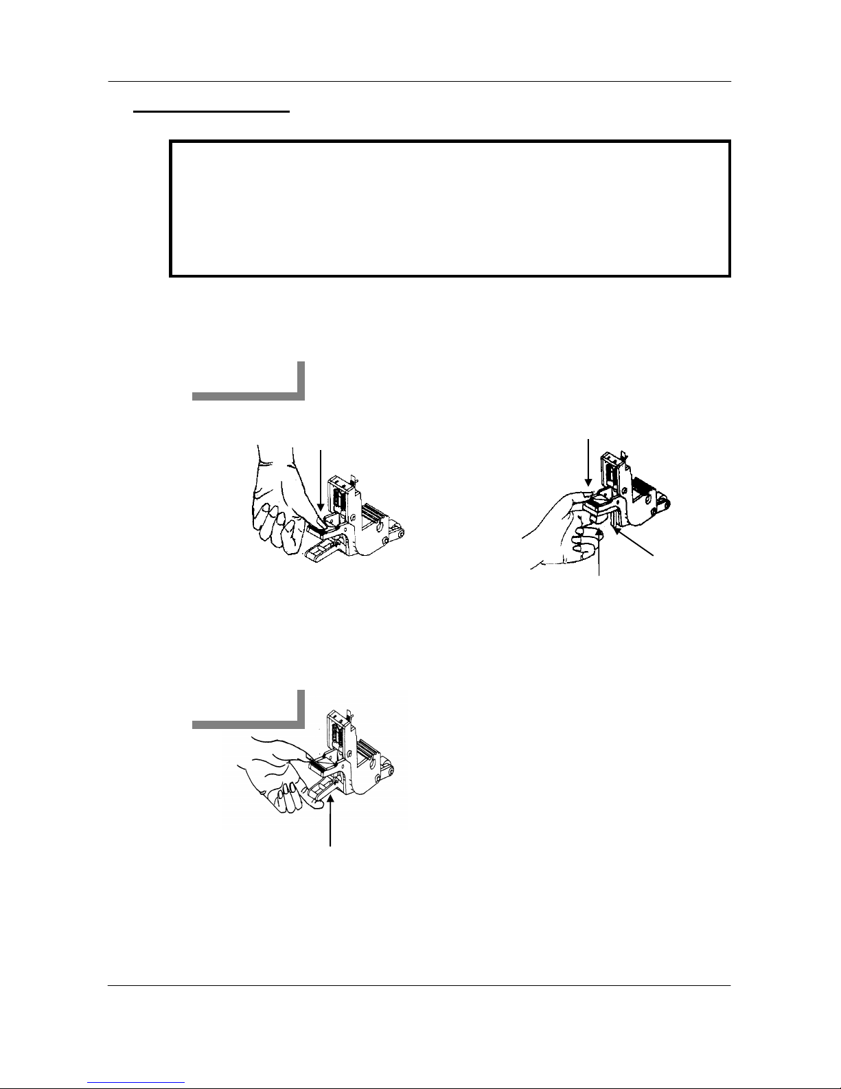
Always put the pinch rollers within the white marks.
Note: Never press the top release grip (the release grip is fully pressed when a
clip sound is heard) and pull the bottom release grip at the same time as the
pictures shown below. This will prevent you from disabling the pinch roller as
the stop bar will not reach the correct position and therefore will not be
functioning.
Pull up bottom to release grip
Disable
Press down
O (Correct)
Stop bar
Push
X (Incorrect)
Enable
Press down
5
V5a 2015 Jan

Table of Contents ValueCut USER MANUAL
Table of Contents
1 General Information ............................................ 9
1.1 Introduction ............................................................................................................... 9
1.2 Package Items ........................................................................................................... 9
1.3 Production Features ............................................................................................... 11
1.4 Appearance of ValueCut ......................................................................................... 12
1.4.1 The Front View ....................................................................................................................... 12
1.4.2 The Back Vuew ...................................................................................................................... 13
1.4.3 The Whole View of ValueCut .................................................................................................. 13
1.4.4 The Left Side View ................................................................................................................. 14
1.4.5 The Right Side View ............................................................................................................... 14
2 Installatopn ........................................................ 15
2.1 Precaution ............................................................................................................... 15
2.2 Stand & Flexible Media Support System (VC-1300/1800) .................................... 16
2.3 Desktop Flexible Media Support System (VC-600) .............................................. 22
2.4 Instruction of Damper Roller ................................................................................. 24
2.5 Installation of Media Basket System ..................................................................... 25
2.6 Cutting Pad Installation .......................................................................................... 28
2.7 Blade Installation .................................................................................................... 30
2.8 Automatic Blade Length Detection ....................................................................... 32
2.9 Cable Connection ................................................................................................... 34
3 The Control Panel ............................................. 35
3.1 The LCD Panel ........................................................................................................ 35
3.2 Menu in On-line mode ............................................................................................ 36
3.3 Menu in Off-line Mode ............................................................................................ 37
3.4 Menu Items .............................................................................................................. 39
4 Operation ........................................................... 43
4.1 Media Loading ......................................................................................................... 43
4.1.1 Loading the Sheet Media ....................................................................................................... 43
6
V5a 2015 Jan

ValueCut USER MANUAL Table of Contents
4.1.2 Loading the Roll Media ........................................................................................................... 45
4.2 Tracking Performance ............................................................................................ 48
4.3 Cutting Force and Offset Adjustment ................................................................... 49
4.4 How to Cut 3mm Letters ........................................................................................ 50
4.5 How to Make A Long Plot ....................................................................................... 50
4.6 When Completing the Cutting Job ........................................................................ 51
5 Automatic Aligning System II .......................... 52
5.1 Introduction ............................................................................................................. 52
5.2 AAS Calibrating the System .................................................................................. 53
5.2.1 Media Calibration ................................................................................................................... 53
5.2.2 AAS Calibration ...................................................................................................................... 53
5.2.3 AAS II on ValueCut ................................................................................................................. 54
5.3 Printer Test .............................................................................................................. 56
5.4 Registration Mark Offset Range ............................................................................ 58
5.5 Contour Cutting ...................................................................................................... 58
5.6 Tips for AAS ............................................................................................................ 60
6 Maintenance ...................................................... 61
6.1 Cleaning the Cutting Plotter .................................................................................. 61
6.2 Cleaning the Grid Drum ......................................................................................... 62
6.3 Cleaning the Pinch Rollers .................................................................................... 62
7 Trouble Shooting .............................................. 63
7.1 Non-operation Problems ........................................................................................ 63
7.2 Operational Problems ............................................................................................ 64
7.2.1 LCM Error Messages ............................................................................................................. 64
7.2.2 Other operational problems .................................................................................................... 65
7.3 Cutting Plotter/Computer Communication Problems .......................................... 67
7.4 Software Problems ................................................................................................. 68
7.5 Cutting Quality Problems ....................................................................................... 69
8 FlexiSTARTER Quick Start Guide .................... 70
8.1 Introduction ............................................................................................................. 70
8.2 Install of the FlexiSTARTER ................................................................................... 70
8.3 Start up of the FlexiSTARTER ................................................................................ 71
8.4 Add Device by Using the Production Manager .................................................... 72
8.5 Initial Settings of the Production Manager ........................................................... 73
8.5.1 Change to the setting of leaving job that finishes runnin g ...................................................... 73
7
V5a 2015 Jan

Table of Contents ValueCut USER MANUAL
8.5.2 Change unit of measures used in the Production Manager .................................................... 74
8.6 Basic Settings ......................................................................................................... 75
8.6.1 Overview of the FlexiSTARTER screen .................................................................................. 75
8.6.2 Standard T oolbar .................................................................................................................... 76
8.6.3 Main T oolbar ........................................................................................................................... 77
8.7 Create the Character .............................................................................................. 78
8.7.1 Cut/Plot Window ..................................................................................................................... 79
8.8 Cut the Character .................................................................................................... 80
8.9 Create Date of the Contour Cut Line ..................................................................... 82
8.9.1 Procedure of the cut contour .................................................................................................. 82
8.9.2 Read in the data of the Adobe Illustrator ................................................................................ 82
8.9.3 Create data of the contour cut line ......................................................................................... 83
8.9.4 Cut contour mark .................................................................................................................... 84
8.9.5 Create a cut contour mark ...................................................................................................... 85
8.10 Cut Contour ........................................................................................................... 86
8.10.1 Image Print ........................................................................................................................... 86
8.10.2 Cut contour window .............................................................................................................. 86
8.10.3 Cut Contour .......................................................................................................................... 87
8.11 Feature List ............................................................................................................ 88
8.12 Troubleshooting .................................................................................................... 90
8.12.1 Can not send the data from FlexiSTARTER ......................................................................... 90
8.12.2 How to change the pen up speed ......................................................................................... 90
9 Appendix ........................................................... 91
9.1 ValueCut Specification ........................................................................................... 91
9.2 Blade Specification ................................................................................................. 92
9.3 About the T ool ......................................................................................................... 93
9.4 Consumable and Optional Item List ...................................................................... 94
8
V5a 2015 Jan

ValueCut USER MANUAL General Information
1 General Information
1.1 Introduction
ValueCut series c utt i ng plotters have been designed to produce computer-generated images or perform
contour cutting on sheets or rolls of vinyl media.
This manual covers the following models of ValueCut series cutting plotters:
‧VC-600 for media width: 50mm(1.97”) ~ 770mm(30.3”)
‧VC-1300 for media width: 50mm(1.97”) ~ 1594mm(62.7”)
‧VC-1800 for media width: 300mm(11.8”) ~ 1900mm(74.8”)
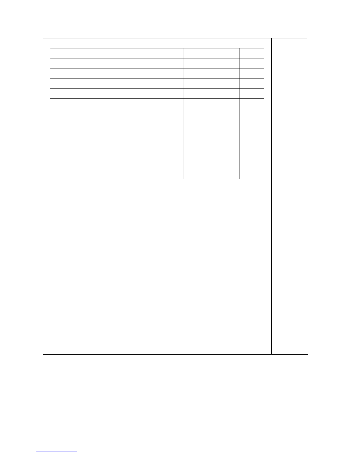
1.2 Package Items
The package of the ValueCut model contents the items listed below, please check carefully.
If you find any item missing, please consult your local dealer for further ass ist anc e.
SSttaannddaarrdd IItteemm
QQuuaannttiittyy
1. Cutting Plotter Main unit 1
2. Stand Set ( for VC-1300/1800 only )(Optional for VC-600)
2 piece of T-shape stand
1 piece of stand beam
18 pieces of M6 screws
1 piece of M5 L-shape hexagon screw driver
1 piece of Installation Guide for Stand Set
1
9
V5a 2015 Jan
General Information ValueCut USER MANUAL
3. Flexible Media Support System Package
Items VC-1300/1800 Only VC-600
1 set of Roll Media Flange (2 pieces) V V
1 set of Roll Holder (2 pieces) V V
1 set of Roll Holder Guide Bushes (4 pieces)
V V
1 set of Roll Holder Support (2 pieces) V V
1 piece of M6 L-shape hexagon screw driver V V
1 piece of Installation Guide for Roll Holder V
1 piece of M5 L-shape hexagon screw driver
V
1 set of Desktop Support Brackets (2 pieces) V
4 pieces of Plastic Foot V
4 pieces of M4 screws V
12 pieces of M6 screws V
1 piece of M4 L-shape hexagon screw driver
V
1
4.Media Basket (VC-1300/1800 only) (VC-600 : opt.)
2 pieces of Basket Arm
2 pieces of Basket Rod
1 piece of Basket
4 pieces of Basket Screw
2 pieces of Fixtures (for Basket Arms)
8 pieces of M3 screws
1 piece of 2mm L-shape hexagon screw driver
1
5. Accessories
1 piece of User’s Compact Disk
1 piece of data cable (RS-232C 3m)
1 piece of data cable (USB cable 3m)
1 set of Blade Holder Assembly (Installed in tool carriage of the cutting plotter)
1 piece of Blade (45° with Red Cap/ Installed in Blade Holde r)
1 piece of Safe Blade
1 piece of Cutting Pad for Vinyl cutting
1 piece of Tweezers
1 Oily ball-point pen
1
10
V5a 2015 Jan

ValueCut USER MANUAL General Information
1.3 Production Features
The following are the main features of the ValueCut series cutting plotters:
‧ Tri-port connectivity provides you with greater flexibility
‧ Up to 600-gram cutting f orce
‧ Up to 60-inch/per second cutting speed
‧ Guaranty 10-meter trac king
‧ User friendly, multi-language control panel
‧ Ingenious media basket (optional item)
‧ Enhanced Automatic Aligning System for automatic contour cutting
11
V5a 2015 Jan
General Information ValueCut USER MANUAL
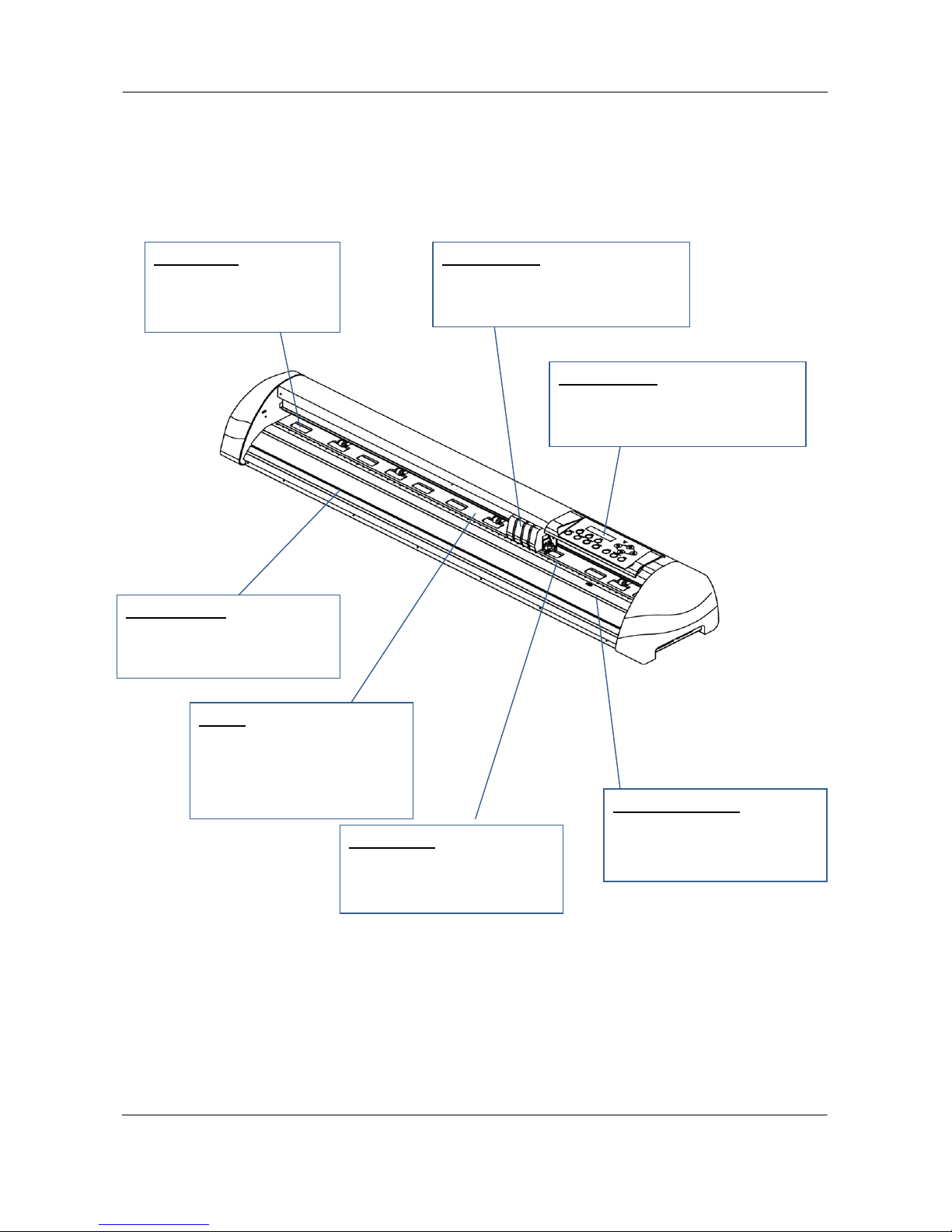
1.4 Appearance of ValueCut
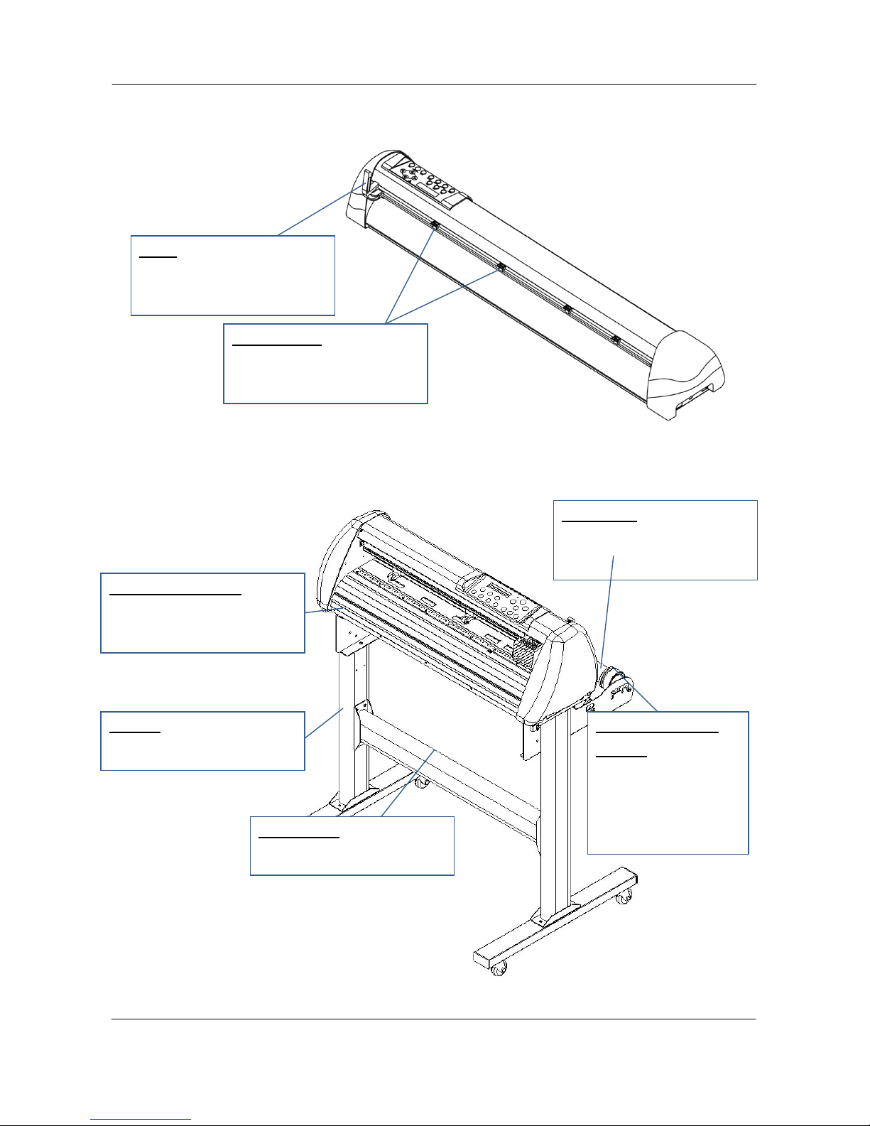
1.4.1 The Front View
Figure 1-1
Grid Drums – move the
media back and forth
during operation.
Tool Carriage – performs the
cutting with the installed blade and
pen with AAS module.
Slicer Groove – slice off the
extra media easily along this
groove.
Platen – provides the surface
for holding and supporting
media while performing cutting.
Alignment Rulers – media
can be aligned with the clear
guide line marks.
Cutting Pad – provides the
protection of blade when the
blade is cutting.
Control panel – consists of 14
control keys and 1 LED and 1 LCM
showing messages and menus.
12
V5a 2015 Jan
ValueCut USER MANUAL General Information
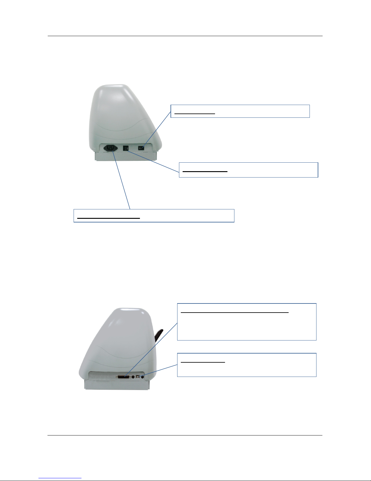
1.4.2 The Back Vuew
1.4.3 The Whole View of ValueCut
Figure 1-2
Figure 1-3
Pinch Rollers –
hold the media during cutting.
Lever –
raises or lowers the pinch
rollers.
Roll Holder – holds and
supplies the roll media for
cutting.
Roll Holder Guide
Bushes – serve to keep
the roll media in place
when media is pulled
from the roll.
T-Stand –supports the cutti ng
plotter body.
Roll Holder Support –
supports roll holders.
Stand Beam – stabilizes the
body.
13
V5a 2015 Jan
General Information ValueCut USER MANUAL
1.4.4 The Left Side View
1.4.5 The Right Side View
Figure 1-4
Figure 1-5
Power Switch – On when switches to [I]; Off to
Circuit Breaker – 3 Amp.
AC Power Connector – used to insert the AC power
Serial Interface Connector (RS232C) – used
to connect the cutting plotter to a computer
through a serial interface cable.
USB Connector – used to connect the cutting
plotter to a computer through a USB cable.
14
V5a 2015 Jan

ValueCut USER MANUAL Installation
2 Installatopn
2.1 Precaution
Please read the following information carefully before you start installation.
Note:
1.
Make sure the power switch is off before installing the cutting plotter.
Carefully handle the cutter to prevent any injuries.
2. Choosing a proper place before setting up the cutting plotter
Before installing your cutting plotter, select a suitable location,
which meets the
following conditions.
The machine can be approached easily from any direction.
Keep enough space for the machine, accessories and supplies.
Keep the working area stable, avoiding sever vibration.
Keep the temperature between 15 and 30
℃
(60-86oF) in the workshop.
The relative humidity of the working environment should be between 25% to 75%.
Protecting the machine from dust and strong air current.
Preventing the machine from direct sunlight or extremely bright lighting.
3. Connecting the Power Supply
Check the plug of the power cord to see if it matches with the wall outlet. If not, please
contact your dealer.
Insert the plug (male) into a grounded power outlet.
Insert the other end (female) of power cord into the AC connector of cutting plotter.
15
V5a 2015 Jan
Installation ValueCut USER MANUAL
2.2 Stand & Flexible Media Support System (VC-1300/1800)
Step 1
Please examine supplied items in the accessory box of stand carton:
2 pieces of base beams
2 pieces of side beams
1 piece of stand beam
20 pieces of M6 screws
1 piece of M5 L-shape hexagon screw driver
1 piece of Installation Guide for Stand Set
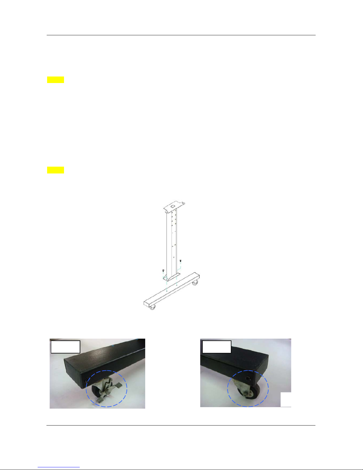
Step 2
Remove the plotter body and the accessories from the s hipped carton.
Assemble the base beam to the side beam with 2 screws to f orm a T-shape stand.
Please pay attention to the direction of the base beam (t he wheel on the front end of the beam comes
with a break while the rear one is on its own).
Figure 2-1
Figure 2-2
Figure 2-3
Front
Rear
16
V5a 2015 Jan
ValueCut USER MANUAL Installation
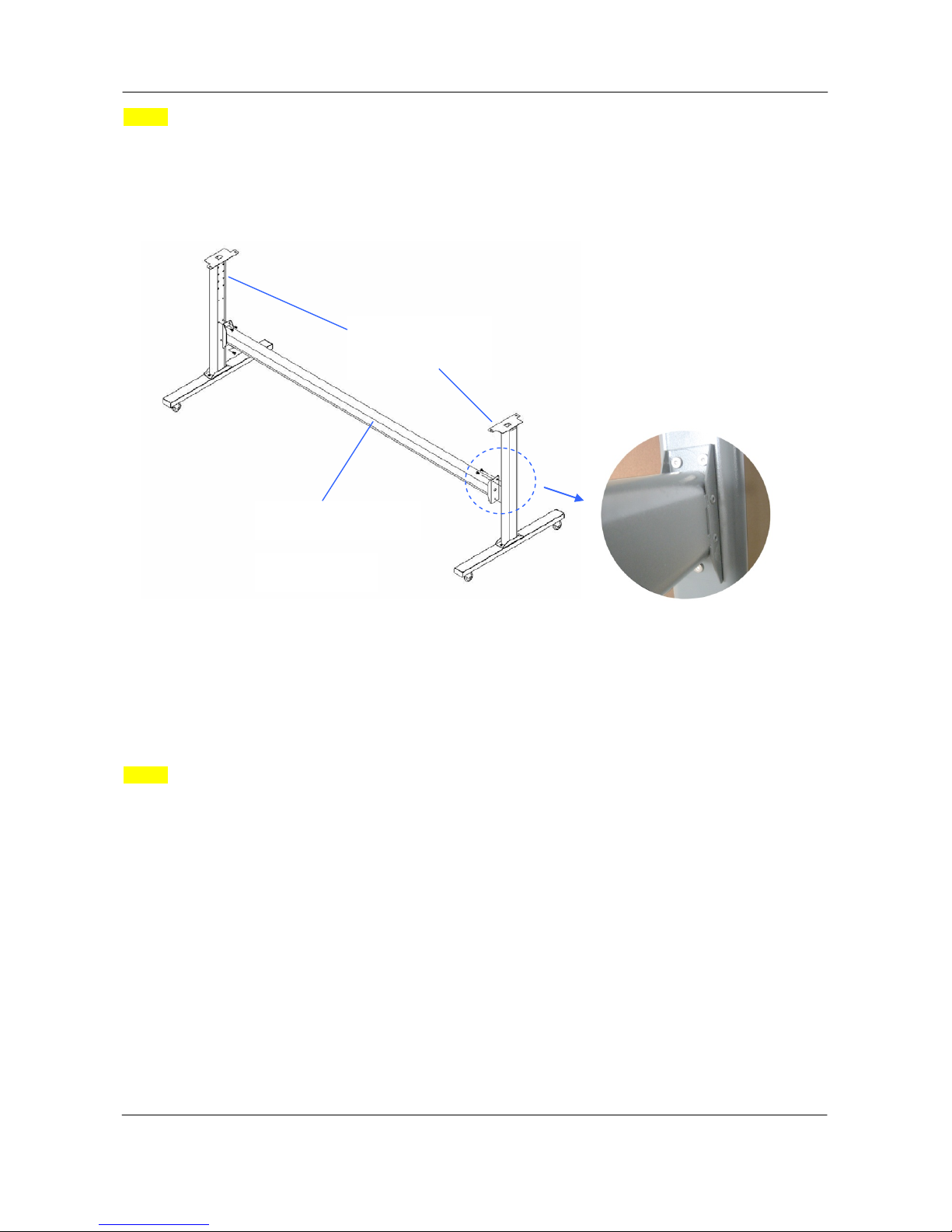
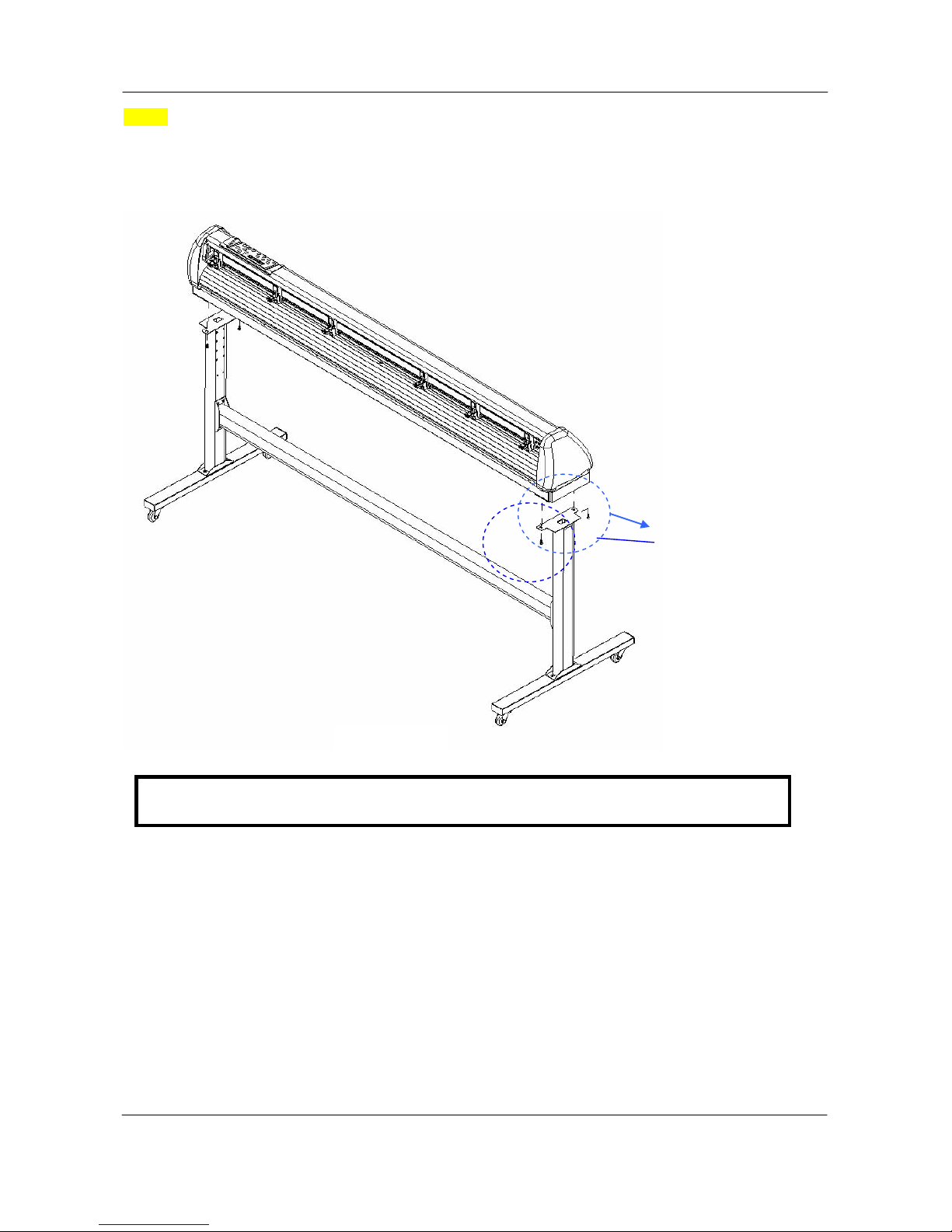
Step 3
Place the stand beam upright on the T-stand and follow number (1) (2)to assemble. (See Figure
2-4 & 2-5)
Step 4
Position the stand beam perpendicularly to part (1)and put the screws into the holes and tighten them as
Figure 2-5. Then the complete picture of stand will be like Figure 2-4.
(1) T-Stand
(2) Stand beam
Figure 2-4
Figure 2-5
17
V5a 2015 Jan
Installation ValueCut USER MANUAL
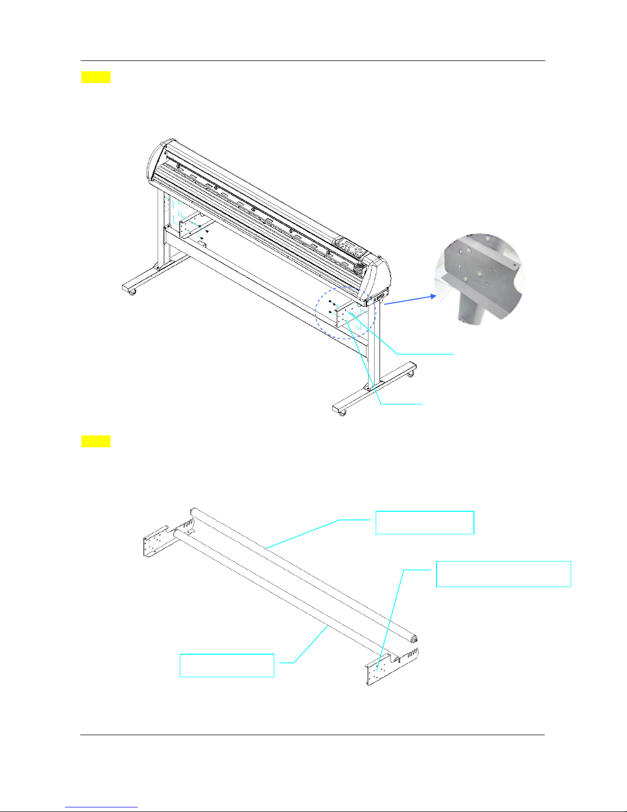
Step 5
Remove the cutting plotter from the carton. Position your stand under the plot ter, and then insert the
screws into the holes on plotter’s bottom and tighten them up as shown in Figure 2-6.
を
Screw(M6)
Figure 2-6
Note: The cutting plotter needs to be assembled by at least two people.
18
V5a 2015 Jan
ValueCut USER MANUAL Installation
Step 6
Insert the roll holder support with the screws into the holes of the stand, and then tighten them up as
shown in Figure 2-7. You could decide roll holder support’s position by insert i ng into different holes.
Step 7
Place roll holder 1 into the holes in the roll holder support. (Figure 2-8)
Roll holder support
Roll holder 1
Figure
2-8
Roll holder support
3 screws
Roll holder 2
Figure 2-7
19
V5a 2015 Jan
Installation ValueCut USER MANUAL
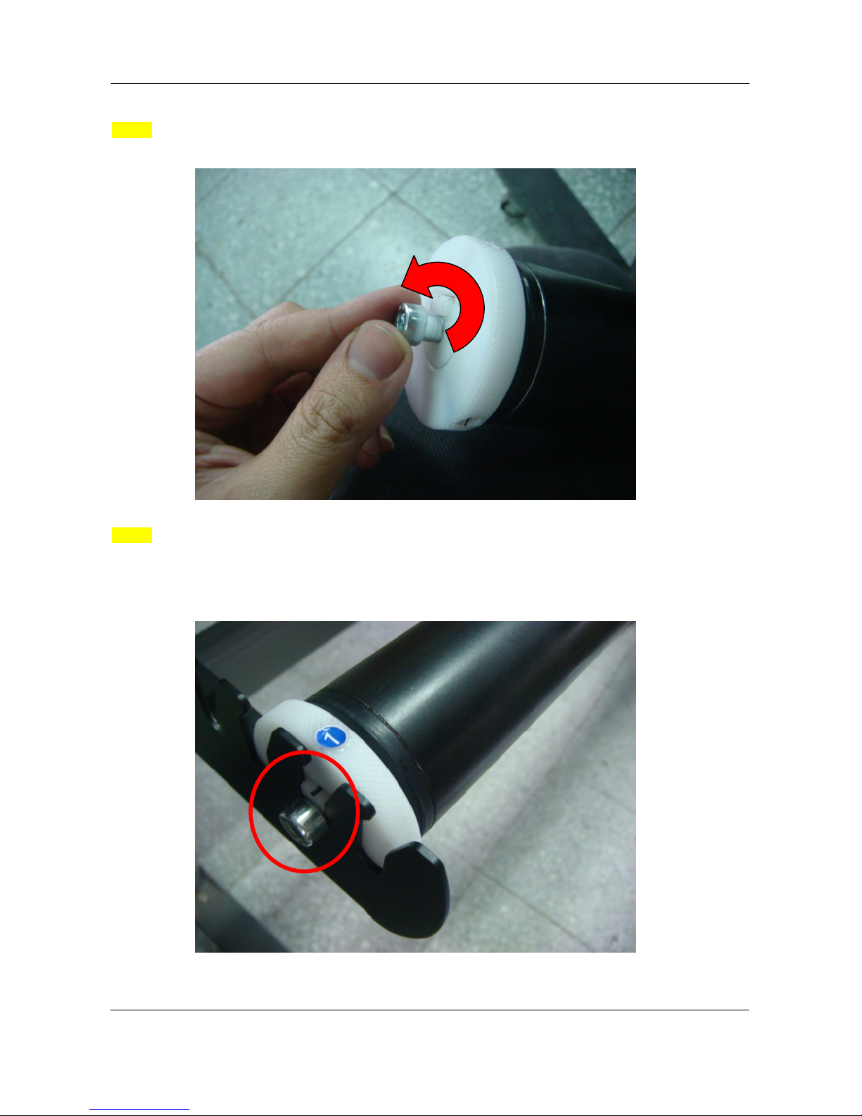
Step 8
Turn the screw counter-clockwisely for around three times after unpacking roll holder 2 (Figure 2-9).
Step 9
Insert the end of the roll holder without the damper into the left roll holder support and then insert the end
of the roll holder with the damper into the right roll holder support. Ensure the white protrusion is wedged
in the groove (Figure 2-10).
Figure 2-9
Figure 2-10
20
V5a 2015 Jan
ValueCut USER MANUAL Installation
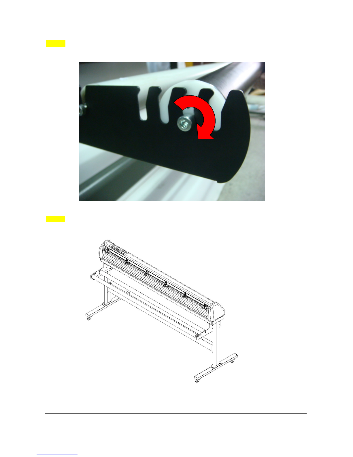
Step 10
Tighten the screw on the damper until it is securely attached to the right roll holder support (Figure 2-11).
Step 11
Lastly, the complete picture will be shown like below (Figure 2-12).
Figure
2-12
Figure 2-11
21
V5a 2015 Jan
Installation ValueCut USER MANUAL
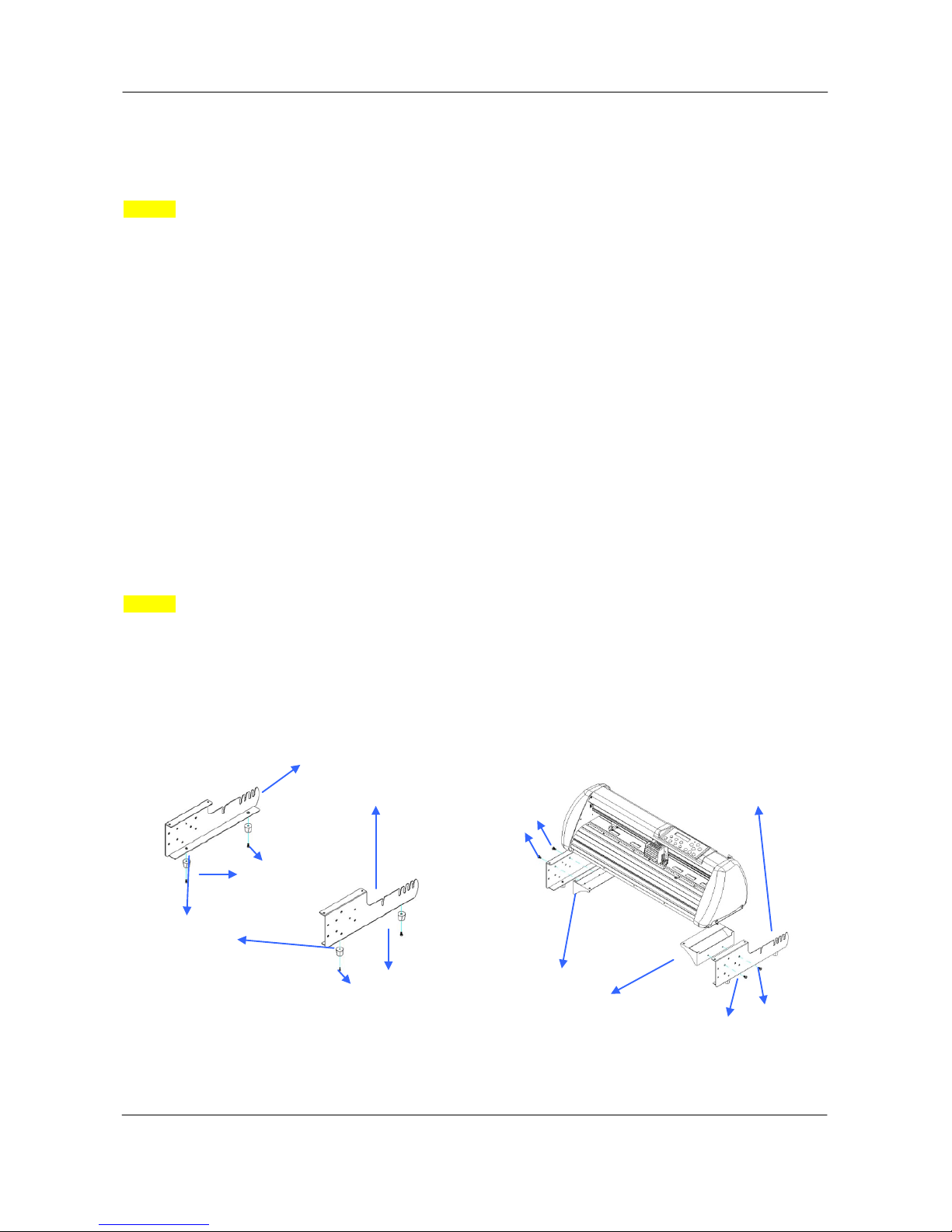
2.3 Desktop Flexible Media Support System (VC-600)
Step 1
Please examine the following items in stand carton’s accessory box:
1 set of Roll Media F l ange (2 pieces)
1 set of Roll Holder ( 2 pieces)
1 set of Roll Holder Guide Bushes (4 pieces)
1 set of Roll Holder Support (2 pieces)
1 set of Desktop Support Bracket (2 pieces)
4 pieces of Plas tic Foot
4 pieces of M4 screws
12 pieces of M6 screws
1 piece of M4 L-shape h exagon screw driver
1 piece of M5 L-shape h exagon screw driver
1 piece of M6 L-shape h exagon screw driver (for adjusting the screws of Roll Hol ders)
1 piece of Installation Guide for Roll Holder
Step 2
Put the 4 Plastic Foot under the Roll Holder Support and insert the M4 screw into the hole of Plastic Foot
and tighten them with the M4 L-shape screw driver. (Figure 2-13
)
M6 screws
Figure 2-14
M6 screws
Figure 2-13
M4 screws
Plastic
M4 screws
Roll Holder Support Roll Holder
Support
Desktop Support Brackets
22
V5a 2015 Jan
ValueCut USER MANUAL Installation
Step 3 Position the Desktop Support Brackets beside the Roll Holder Support and insert M6 screws
into the Roll Holder Support and tighten them with M6 L-shape screw driver. (Refer to Figure 2-14 at the
left).
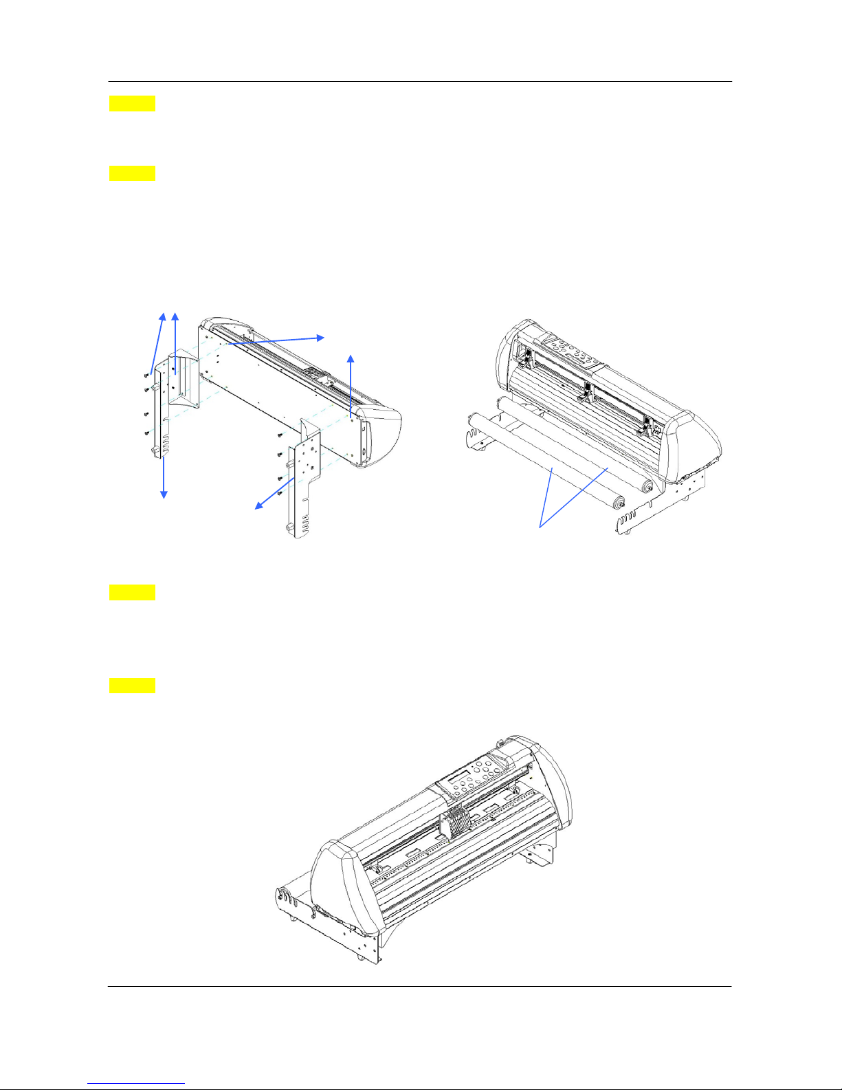
Step 4
Put the bottom of machine in lateral, and position the Roll Hol der Assembly beside the bottom of the
machine. Then, insert the M6 screws into the holes of Roll Holder support assembly and tighten them
with M6 L-shape screwdriver. Like Figure 2-15.
Step 5
Place the two roll holders into the holes of Roll Holder Support (Figure 2-16). T o install the roll holder with
damper, please refer to chapter 2.2, step 8 to step 10.
Step 6
The complete Desktop Media Support System will be shown as in Figure 2-17.
Figure 2-17
Figure 2-16
Roll Holder Shaft
Figure 2-15
Screw holes
M6 screws
Roll Holder Assembly
23
V5a 2015 Jan
Installation ValueCut USER MANUAL
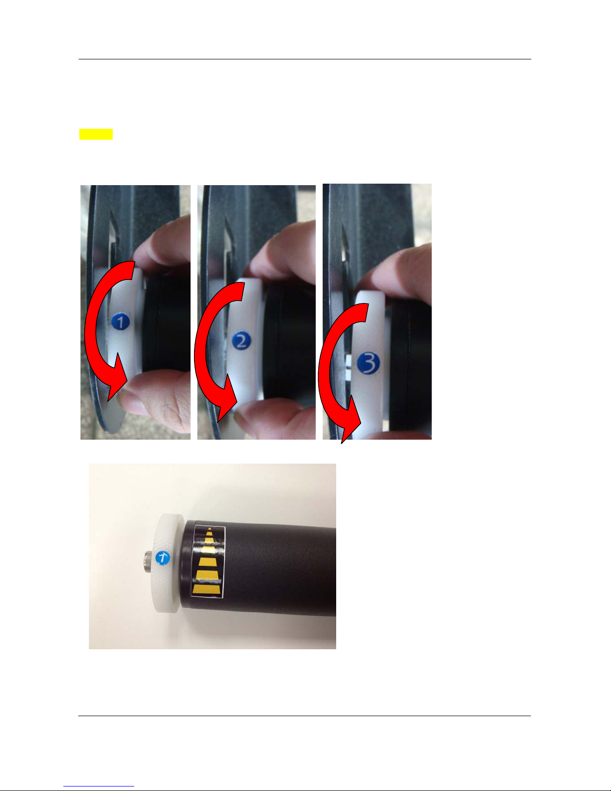
2.4 Instruction of Damper Roller
Step 1
Turn the wheel as instructed below to adjust damping. The bigger the number is, the stronger the
damping. The volume symbol sticker indicates the damping level (Figure 2-18, 2-19).
Figure 2-18
Figure 2-19
24
V5a 2015 Jan
ValueCut USER MANUAL Installation
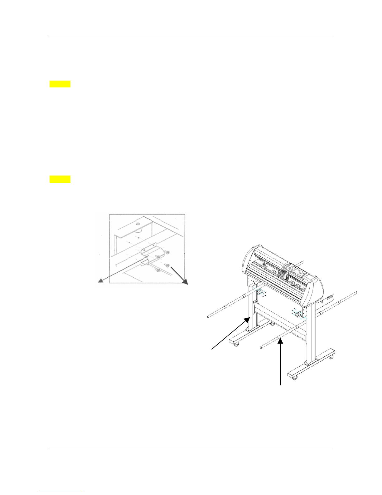
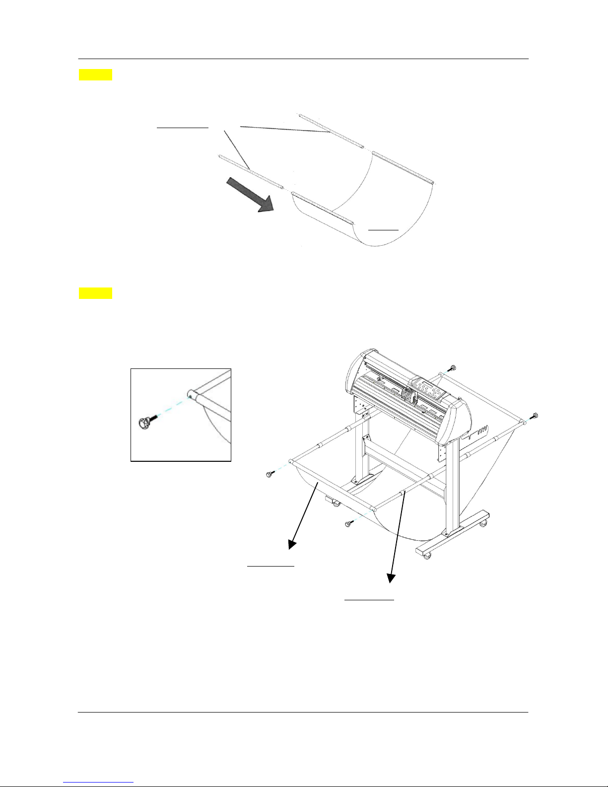
2.5 Installation of Media Basket System
Step 1
Please examine the supplied items in the accessory box
2 pieces of basket arms
2 pieces of basket rods
1 piece of basket
2 pieces of fixtures (for basket arms)
8 pieces of M3 screws
1 piece of 2mm L-shape hexagon screw driver
Step 2
First, place the basket arms beside the stand and fix them with fixtures. Then insert the M3 screws and
tighten them with the 2mm L-shape screw driver. (See Figure2-20)
Stand
M3 screws
Fixtures
Figure 2-20
Basket arm
25
V5a 2015 Jan
Installation ValueCut USER MANUAL
Step 3
Insert the basket rods to the basket holes (See Figure 2-21)
Step 4
Loosen the basket screws from the basket arms. Posit i on the basket rod in front of the basket arms and
insert the basket screws into the holes on the basket rod and tighten them. (Figure 2-22)
Basket rods
Basket
Basket rod
Basket arm
Figure 2-21
Figure 2-22
26
V5a 2015 Jan
ValueCut USER MANUAL Installation
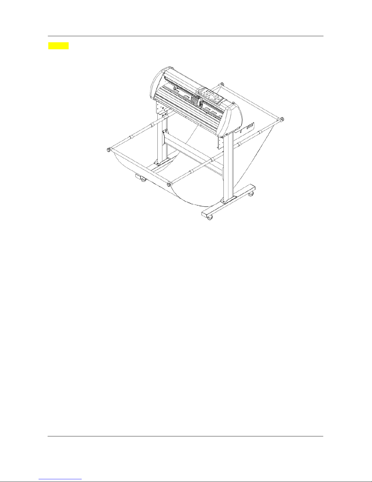
Step 5
The complete Media Basket System will be like Figure 2-23.
Figure 2-23
27
V5a 2015 Jan
Installation ValueCut USER MANUAL
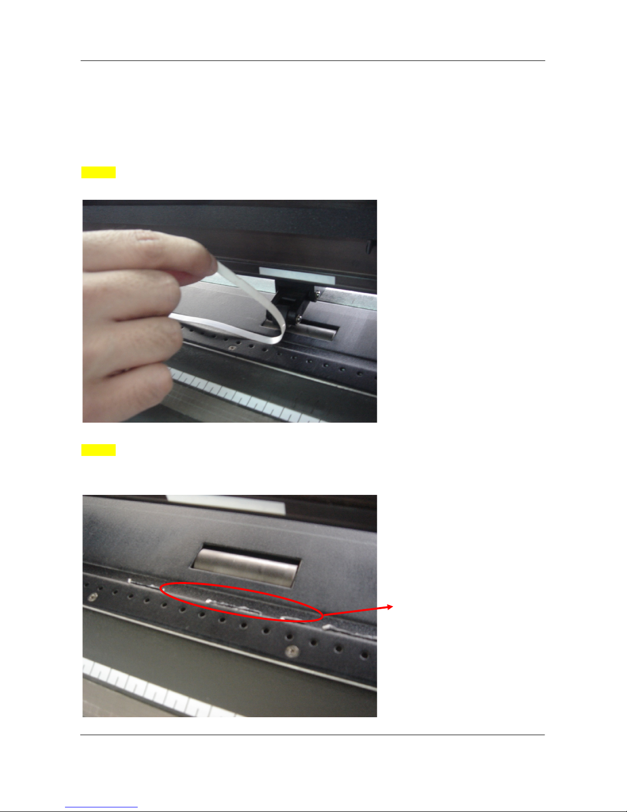
2.6 Cutting Pad Installation
1 piece of cutting pad is included in the accessory pack. F ol low the instruction below to install
a new cutting pad when the existing pad is worn out.
Step 1
Carefully remove the cutting pad from the unit.
Step 2
Remove the remaining adhesive on the groove with alcohol or cleaning naphtha.
Remaining adhesive
Remaining adhesive
Figure 2-24
Figure 2-25
28
V5a 2015 Jan
ValueCut USER MANUAL Installation
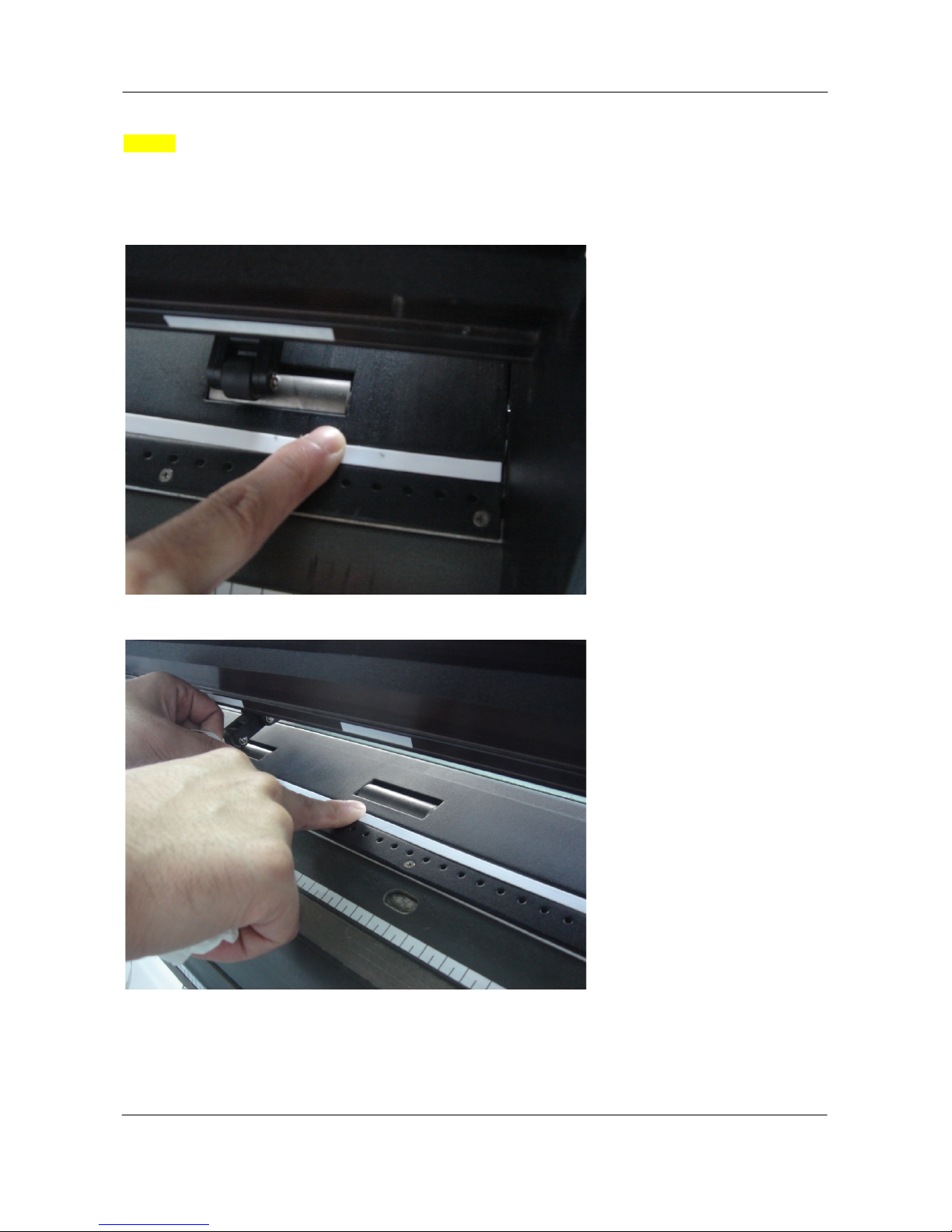
Step 3
Attach the new cutting pad to the groove after unrolling i t and removing the backing sheet and
the installation process is completed.
Figure 2-26
Figure 2-27
29
V5a 2015 Jan

Installation ValueCut USER MANUAL
2.7 Blade Installation
Figure 2-28 is the ill ustrator of the blade hold er. Insert a blade into the bottom of the blade holder and
remove the blade by pushing the pin. Make sure that your fingers are awa y from the blade tip.
Step 1
Install blade (Figure 2-29).
Step 2
Push the blade to the bottom of the blade holder. (Figure 2-30).
Step 3
Adjust the blade tip to suitable length by screwing
“Blade tip adjustment screw” clockwise orcount-clockwise. (Figure 2-31).
Figure 2-31
Figure 2-30
Tips:
“The proper length” means the blade’s length
is adjusted 0.1mm more than film’s thickness.
That is, if the thickness of film is 0.5mm, then
blade’s length is properly adjusted 0.6mm and
it can completely cut through the film layer yet
avoid penetrating the backing.
Figure 2-28
Outward ring
Adjustment depth knob
Figure 2-29
Pin
30
V5a 2015 Jan

ValueCut USER MANUAL Installation
Step 4
Insert the blade holder into tool carriage. Please note the outward ring of the holder must put into the
grooves of carriage firmly (see Figure 2-32), then fasten the case (Figure2-33).
Step 5
Use the reversing steps to remove the blade holder.
Step 6
Eject the blade. Push “Blade eject pin” to eject blade when the blade needs to be replaced.
Note:
The blade will lose its sharpness after a period of us age, the cutting quality might be affected.
By increasing the cutting force, it mi ght do the trick. However, once the blade is worn out and no
longer provides a reliable cutting, you should repla ce a new one. The bl ade is cons umable and must
be replaced as often as necessary to maintain the cutting quali ty. The quality of the blade deeply
affects cutting quality. So be sure to use a high quality blade to ensure good cutting results.
Figure 2-32 Figure 2-33
31
V5a 2015 Jan

Installation ValueCut USER MANUAL
Figure 2-34
Figure 2-35
2.8 Automatic Blade Length Detection
Figure 2-34 is the new blade holder with a scale and the carriage with a mark . T his blade holder det e ct s
blade length automatically and shows how the knob needs to be turned on the LCM.
There are 10 units on the scale; each unit equals t o 0.05 mm, allowing you to adjust the blade length for
0.00mm-5.00mm (Figure 2-35).
Follow the steps below to adjust the length of the blade:
1. Keep the blade tip within the blade holder before you s tart adjusting.
2. Align one of the scales on the blade holder to the mark on the carriage
3. Select “Blade Length Adjust” under “CUT TEST” on the LCM, enter the blade length wished in “Set
Length”; test the blade holder first and then test the blade length by pressing ENTER.
Mark
Scale
1 unit
Note:
Keep the blade holder at the same position when you perform blade holder and blade length tests.
32
V5a 2015 Jan

ValueCut USER MANUAL Installation
Figure 2-37 Figure 2-36
4. When blade holder and blade length tests are finished, t he screen will show you to what degree (the
unit of the value following “CW” or “CCW” is “circle”) and in which directi on [CW (clockwise) or CCW
(counterclockwise)] you should turn the adjustm ent knob.
EG, Turn CW 5 is telling you that you should turn t he knob for 5 units clock-wisely (Figure 2-36,
Figure 2-37).
5. The screen will show "Adjustment completes " when the value on the screen is 0, the blade length is
perfect and no more adjustment needs to be made. Press "Enter" now to complete the process and
you may start cutting at this point.
33
V5a 2015 Jan

Installation ValueCut USER MANUAL
2.9 Cable Connection
The cutting plotter communicates with a computer through a USB (Universal Serial Bus) or a
Serial port (RS-232C). This chapter shows you how to connect the cutting plotter to a host
computer and how to set up the computer/cutting plotter interconnection.
Figure 2-38
Serial port
Note:
When USB connection is enabled, both parallel port and serial port will be disabled automatically
USB port
34
V5a 2015 Jan

ValueCut USER MANUAL Control Panel
3 The Control Panel
This chapter describes the button operations with the LCM menu flowcharts of ValueCut.
When the cutting plotter is ready for use as des cribed in Chapter 1 & 2, all functions are
under default parameters.
3.1 The LCD Panel
SPEED FORCE OFFSET
MISC TOOL SELECT DATA CLEAR CUT TEST
ON/OFF
LINE
PAUSE / RESUME ENTER
POWER
< LCD Control Panel on ValueCut series >
Key Function
LCD Screen To display functions and error messages.
Power LED To indicate the power status ( light up: power on; light off: power off )
4 Arrow Keys To move position, select function, or change setting.
ENTER To set item or register the immediately preceding input value.
PAUSE/RESUME To temporarily halt cutting process or to continue
ON/OFF LINE To switch modes, stop cutting job, or abort changes of setti ngs.
OFFSET To adjust the value of blade’s offset.
FORCE To adjust the value of cutting force.
SPEED To adjust the value of cutting speed and quality.
CUT TEST To perform cutting tests in different ways.
DATA CLEAE To clear up buffer memory.
TOOL To select tools.
MISC To set up functions.
Please see details "3.4 Menu Items"
35
V5a 2015 Jan

Control Panel ValueCut USER MANUAL
3.2 Menu in On-line mode
Power On ValueCut in processing
Sending data
[
PAUSE
]
[ FORCE]
[ SPEED ]
[ OFFSET ]
[ DATA CLEAR ]
[TOOL SELECT ]
Top menu
Speed--- Force----- Offset---- Length---- Width----Tool set----Metric
MUTOH
LCM Version 1.3
Firmware V3.01
VC-1300
Place Media And Then
Lower Up The Lever
Roll Edge Single
~ Key | Key } Key
Sizing Media Width
Lever Down To Abort
Sizing Media Length
Lever Down To Abort
Pause
Setup RESUME
Force: 80 gf ~
Ok:ENTER|
Speed: 72 cm/s~
Select:{} Ok:ENTER|
UP Speed: 72 cm/s~
Select:{} Ok:ENTER|
Quality: Normal~
Select:{} Ok:ENTER|
Offset: 0.250 mm ~
Ok:ENTER|
Clear data memory
N:ONLINE Ok:ENTER
1S 72 F 80 O0.250M
Select:{} Ok:ENTER|
Set Smoothing Cut
Select:{} Ok:ENTER
OverCut: 0.00 mm ~
Select:{} Ok:ENTER|
Set Tangential Mode
Select:{} Ok:ENTER
Pouncing: 0 mm ~
Select:{} Ok:ENTER|
S 72 F 80 O 0.250
L: 150000W: 914 T1M
36
V5a 2015 Jan

ValueCut USER MANUAL Control Panel
Ratio: 100% - 400%
Pattern: Cross, Arrow
3.3 Menu in Off-line Mode
Press [ON/OFF LINE] to switch to the offline mode
Draft, Fair, Normal, Fine, Small Letter
[CUT TEST ]
Offline For
System Setup
Force: 80 gf ~
Ok:ENTER|
Offset: 0.250 mm ~
Ok:ENTER|
Clear data memory
N:ONLINE Ok:ENTER
Speed: 72 cm/s~
Select:{} Ok:ENTER|
UP Speed: 72 cm/s~
Select:{} Ok:ENTER|
Quality: Normal~
Select:{} Ok:ENTER|
~|{} move origin
X: Y:
Square Cut
Select:{} Ok:ENTER
Repeat AAS Job
Select:{} Ok:ENTER
Redo Jobs in Memory
Select:{} Ok:ENTER
Pattern Setting
Select:{} Ok:ENTER
Pattern: Arrow
Change:~| Ok:ENTER
Ratio Setting
Select:{} Ok:ENTER
Ratio: 100 %
Change:~| Ok:ENTER
Blade Length Adjust
Select:{} Ok:ENTER
Set Length 0.00 mm
Change:~| Ok:ENTER
Test Blade Holder
Ok:ENTER
Test Blade Length
Ok:ENTER
Turn CW 1 Turn
N:ONLINE Ok:ENTER
[ FORCE]
5~600 with an increment of 5(gram force)
[ OFFSET ]
[ DATA CLEAR ]
Speed:3~153 with an increment of 3(cm/s)
[ SPEED ]
0.000~1.000 with an increment of 0.025(mm)
UP Speed:3~153 with an increment of 3(cm/s)
[ Arrow Key ]
37
V5a 2015 Jan

Control Panel ValueCut USER MANUAL
Offline For
System Setup
[TOOL SELECT ]
[ MISC ]
use~|to select from 1S to 4S; [ENTER] to adjust the
parameters
1S 72 F 80 O0.250M
Select:{} Ok:ENTER|
Pouncing: 0 mm ~
Select:{} Ok:ENTER|
Panel Setup
Select:{} Ok:ENTER
OverCut: 0.00 mm ~
Select:{} Ok:ENTER|
Set Tangential Mode
Select:{} Ok:ENTER
Set Smoothing Cut
Select:{} Ok:ENTER
Restore default ?
Select:{} Ok:ENTER
Pouncing:0-200mm with an
increment of 1mm
OverCut:0.00-3.00mm with an
increment of 0.05mm
Image Scale Width
Select:{} Ok:ENTER
Image Scale Length
Select:{} Ok:ENTER
Select Units
Select:{} Ok:ENTER
Select Language
Select:{} Ok:ENTER
Set Communication
Select:{} Ok:ENTER
Paper Saving Mode
Select:{} Ok:ENTER
AAS Offset
Select:{} Ok:ENTER
First Back To Origin
Select:{} Ok:ENTER
Vcuum
Select:{} Ok:ENTER
Auto Unrolled Media
Select:{} Ok:ENTER
Metric (cm/gf) or English
English
Both Expanded Mode、Length Expanded Mode
、
Width Expanded Mode、Both Unexpanded Mode
Select Language
Select:{} Ok:ENTER
38
V5a 2015 Jan

ValueCut USER MANUAL Control Panel
3.4 Menu Items
Below describes the functions of menu items
Menu or Key Function Setting Default
--- Media sizing ---
Place Media
And Then
Lower Down
The Lever
To instruct the user to lower the lever after the materi al is
loaded.
When the medium is loaded, the user will be requested t o
lower the lever; once the lever is lowered, users can proceed
to the three sizing modes (Roll/Edge/Single).
Roll
To measure media width.
Maximum Tracking
150 meters
Edge
To measure media width and pull the media back till the front
paper sensor open.
Maximum Tracking
150 meters
Single
To measure media width and length.
Maximum Tracking
10 meters
--- POWER ---
To indicate the power status.
[ Arrow Keys ]
1. To move the tool carriage position on X or Y axis.
2. To select functions or change values of settings.
[ ENTER ]
1. The displayed parameters will be saved automatically.
2. To set a new origin at the present tool carriage posit i on.
In “offline” mode, moving the tool carriage to desired
position by [Arrow Keys], then press [ENTER] key to set a
new origin. While moving with the parameters of XY-axes
displayed, press [MISC] key will enable fine-tune
movement; press [MISC] key again to disable the function.
[ PAUSE/RESUME ]
To temporarily halt the cutting process.
To resume the process by press [Pause/Resume] key again.
[ ONLINE/OFFLINE ]
1. To switch between online mode and offline mode.
2. To stop the cutting job or abort the change of setting.
Once press this key, the cutting job will be terminated
immediately and cannot be resumed.
[ OFFSET ]
To set or modify the distance between the blade tip and the
center axis.
Please refer to section 4.3 or Chapter A-2 for more
information.
0.000~1.000mm
0.250mm
[ FORCE ]
To set or modify the value of tool force.
When the cutting force exceeds 450g, the maximum c ut ting
speed would be 15cm/sec and the cutting quality would be
Small Letter Mode (0.2g) and while the cutting force is
5~600gram;
5 gram/ step
80 gram
39
V5a 2015 Jan

Control Panel ValueCut USER MANUAL
300g-449g, the maximum cutting speed would be 30 cm/sec
and the cutting quality would be Fine Mode (0.5g)
[ SPEED ]
Speed
To set or modify tool down speed at horizontal moving.
3~153cm/sec;
3cm/sec per step
72cm/sec
Up Speed
To set or modify tool up speed at horizontal moving.
3~153cm/sec;
3cm/sec per step
72cm/sec
Cutting Quality
To set or modify cutting quality.
While cutting small letter, set as “Small letter”.
While cutting in high speed, set as “Draft”.
For normal operation, set as “Normal”.
Draft(4.2G),
Fair(2.8G),
Normal(1.4G),
Fine(0.7G),Small
Letter(0.2G)
Normal
[ CUT TEST ]
Square Cut
To perform a cutting test at present blade position.
For more information, please refer to “4.3 Adjusting the
Cutting Force and Offset” to adjust blade force and cutting
speed.
Repeat AAS
Job
To repeat AAS jobs automatically without having to operate
on the computer side.
Please be noted that this feature is mainly applied to the
Single paper mode; please ensure a new piece of material
you wish to apply this feature on is loaded and the origin
repositioned to the first registration mark before starting.
When the first AAS job repeat completes, the user will be
offered the choice of “Repeat AAS Job Again”, please
press ”Online/Offline” to return to the main menu.
Repeat Last
Plot
Recut:
To repeat the last job without re-sending the data
.
1~99;
1 per step
Copy:
To copy the last job without re-sending the data.
* 1mm gap will be auto-generated between 2 copies).
* If the media length is not enough to continue, it will show
below message on LCM:
* If both functions are enabled at the same time, t he cutter
will
perform the last setting only.
1~99;
1 per step
Pattern Setting
To provide two patterns for cut test
Note: It is recommended to select “Cross” if you are working
on thick pieces of materials.
“Arrow” and
“Cross” patterns
“Arrow”
Ratio Setting
To adjust the size of the pattern
100%, 200%,
300%, 400%
100%
Blade Length
Adjust
Please see 2.5 Automatic Blade Length Adjustment for further
details.
0.00mm-5.00mm
0.00mm
[ DATA CLEAR ]
To clear up buffer memory.
Out Of Space; #
of Copies finished
40
V5a 2015 Jan

ValueCut USER MANUAL Control Panel
[ TOOL SELECT ]
Set Smoothing
Cut
To enable smooth-cutting function.
This function aims to make connections smoother a nd is
suggested to be disabled when cutting small-sized images or
characters
Enable
Over Cut
To generate an overcut to facilitate weeding.
This function mainly applies to thick materials, aiming to
sharpen corners and ensure perfect connections.
0.00mm-3.00mm
0.05mm/per step
0.00mm
Set Tangential
Mode
To enable the emulated tangential-cutting mode for thicker
media types and small letter cuts.
Note: while the Offset value setting at 0.000 mm, “Set
Tangential Mode” will automatically be disabled.
Enable
Pouncing
To make perforated patterns.
* In order to use this function, Pouncing tool must be installe d.
* Before start pouncing, place pouncing strip on top of the
cutting pad to protect the cutting pad.
* Set the value as 0 mm to disable the pouncing mode.
* Pouncing tool is an optional item.
0~200mm
0mm
Panel Setup
Accept setup command:
To accept commands of the Force, Speed, Cutting Qual i t y,
and Offset only via software.
Control panel only:
To accept commands of the Force, Speed, Cutting Qual i t y,
and Offset only via control panel of the cutter.
Restore Default
To turn all parameters of the menu items to factory-default
settings.
[ MISC ]
Auto Unrolled
Media
To avoid paper jam and motor crash by automatically unroll
media (50cm and up) before cutting while enabled. .
* Auto-unroll only affects on roll/edge media.
* Using Single mode to size media will disable this function
automatically.
* If the length of the rolled media is less than 2 meters or t he
weight is light, it is recommended to set this mode disabled.
Enable
Vacuum
To help improve tracking and cutting accuracy by tur ning on
the fans. If you turn off the vacuum system, the fans
will remain inactive during cutting or plotting.
Enable
First Back to
Origin
To enable the carriage back to the previous origin; w hen
“Enable” is selected and the button Online/Offline has been
pressed, the carriage will go back to the previous origin
while
the selection of “Disable” will not allow the carriage to do so.
Enable
Disable
Enable
AAS Offset
To set or modify AAS offset value.
You can refer to “5.3 Printer Test” for more details.
Paper Saving
Mode
To save media by four different modes:
1. Length expanded mode 2. Width expanded mode
3. Both expanded mode 4. Both unexpanded mode
Length
expanded
mode
Set
Communication
To build up the communication between host computer and
cutter.
Baud Rate is to determine the speed of data transmiss i on.
Data Bits refers to the size of one block of data.
Parity is used to check if data was revived correctly or not.
9600, n, 7, 1, p 9600pbs, 7 Bits with NO Parity
9600,N,8,1
,p
41
V5a 2015 Jan

Control Panel ValueCut USER MANUAL
9600, o, 7, 1, p 9600pbs, 7 Bits with ODD Parity
9600, e, 7, 1, p 9600pbs, 7 Bits with EVEN Parity
9600, n, 8, 1, p 9600pbs, 8 Bits with NO Parity
9600, o, 8, 1, p 9600pbs, 8 Bits with ODD Parity
9600, e, 8, 1, p 9600pbs, 8 Bits with EVEN Parity
19200, n, 7, 1, p 19200pbs, 7 Bits with NO Parity
19200, o, 7, 1, p 19200pbs, 7 Bits with ODD Parity
19200, e, 7, 1, p 19200pbs, 7 Bits with EVEN Parity
19200, n, 8, 1, p 19200pbs, 8 Bits with NO Parity
19200, o, 8, 1, p 19200pbs, 8 Bits with ODD Parity
19200, e, 8, 1, p 19200pbs, 8 Bits with EVEN Parity
Firmware
Version
To display the version number of Firmware and FPGA code.
Select
Language
To select displayed languages on LCM panel in English,
Spanish, Italian, Deutsch, Japanese, Portugue se, P ol ish,
Turkish or French.
English
Select Units
Provide two-unit systems for users convenient.
Metric(cm/g)
Unit(inch/g)
Unit(cm/oz)
English(inch/oz)
Metric
Image Scale
Length
To adjust the scale of media length and width that may cause
by the thickness of the media.
The Denominator is the actual length, and the Numerator is
the ideal length measured from the resultant.
For example, cutting a line with 500.0 mm length. The
procedure as follows:
1. Press the [LEFT ARROW] to choose the Numerator and
select 500.0 mm,
2. Cut the length by sending a graph file,
3. Measure the length then use the [RIGHT ARROW] key to
choose the Denominator, then
4. Press [UP ARROW /DOWN ARROW] to
change the values
of the actual length.
250mm/250mm
500mm/500mm
750mm/750mm
250mm/25
0mm
Image Scale
Width
42
V5a 2015 Jan

ValueCut USER MANUAL Operation
4 Operation
4.1 Media Loading
4.1.1 Loading the Sheet Media
To load the media properly, please follow the procedures listed below:
Step 1
Use the lever on the upper right side of the cutting plotter to raise or lower down pinch rollers. P ull the
lever forward until it makes a clicking sound then the pinc h rollers are raised (
Figure 4-1).
Step 2
Load your media on the platen and slide it under the pinch rollers from either the front side or the
backside. The alignment rulers on the platen extension will help you to adjust the m edia precisely.
Note:
Be sure that the media must cover
the paper sensors on the platen when
loading the media. At least one of the
two paper sensors (Figure 4-2)
should be covered. Once the media
covers the sensor, the cutting plotter
will size the media width and length
automatically.
Paper sensors
Figure 4-2
Lever
Figure 4-1
43
V5a 2015 Jan

Operation ValueCut USER MANUAL
Step 3
Then move the pinch rollers manually to the proper position. Be sure the pinch rollers must be positioned
above the grid drum. The white marks on the top trail will remind you where the gri d drums are (Figure
4-3).
Step 4
Push the lever backward to lower down the pinch rollers.
Step 5
Turn on the power, the tool carriage will meas ure the size of the media automatically. And the plotting
cutter begins to work.
t
Figure 4-4
(X) Incorrect
Note:
1. Always adj ust the position with the pinch roller raised.
2. Move the pinch roller by applying force at the rear portion of the pinch roller support.
3. Do not move it by holding its front rubber roller (Figure 4-4).
White marks
Figure 4-3
44
V5a 2015 Jan

ValueCut USER MANUAL Operation
4.1.2 Loading the Roll Media
Step 1
Put the roll media guide bushes on two roll holders (Figure 4-6).
Pull up bottom to release grip
Figure 4-5
Note:
Please pull up the bottom of all pinch rollers (Figure 4-5) before the lever is pushed backwards to
ensure accurate media width detection.
Enable
Roll media guide bushes
Figure 4-6
45
V5a 2015 Jan

Operation ValueCut USER MANUAL
Step 2
-- Option A (Recommended)
Insert the two roll holders into the roll media support set then place the roll media directly between the
two roll holders (
Figure 4-7).
-- Option B (Use the media flanges )
Insert a roll media flange at the end of each roll
media and tighten the thumbscrew until the roll
media is firmly gripped(see Figure 4-8).
Then put the roll media on the roll holders. Adjust the
position of the roll media ensure that media flanges are
able to run in the grooves of media guide bushes.
(Figure 4-9)
Step 3
Load the media on the platen. Please refer to “4.1.1 Loading the sheet media”. After loading the roll
media, flatten the media on the platen and hold the front edge of the roll media firmly (Figure 4-10).
Figure 4-8
Figure 4-9
Figure 4-7
46
V5a 2015 Jan

ValueCut USER MANUAL Operation
Step 4
Turn the roll downward to make an equal tension across the media (Figure 4-11)
Step 5
Move the pinch rollers to the appraise location and
note that the pinch rollers must be positioned above
the grid drums.
Step 6
Push the lever backward to lower down the pinch rollers.
Step 7
Fix roll media guide bushes on the roll holder to secure the rol l media.
Step 8
Turn on the power switch, the tool carriage will sizing the media automatically.
Then the cutting plotter is ready to work.
Step 9
Use the reverse steps to remove the media.
Note:
Make sure that the media tension is equally distributed from left to right. If the media were not
tightened enough against the platen, it would cause tracking problems!
図
4-11
図
4-10
47
V5a 2015 Jan

Operation ValueCut USER MANUAL
4.2 Tracking Performance
In order to achieve the best tracking performance for a long plot, we recommend some significant media
loading procedures described as follows:
If the media length is less than 4 meters, leave the margin of 0.5mm—25mm in the left and right ed ges
of the media (Figure 4-12).
If the media length is greater than 4 meters, leave at least 25mm margi n on the left and right edges of
the media (Figure 4-13).
Please refer to the paragraph “4.5 How to Make A Long Plot” for more details.
Figure 4-12
Pinch roller
Pinch roller
0.5mm - 25mm
0.5mm - 25mm
Figure 4-13
> or = 25mm
> or = 25mm
48
V5a 2015 Jan

ValueCut USER MANUAL Operation
4.3 Cutting Force and Offset Adjustment
Before sending your designs for cutting, you may perf orm a “cut test” to generate satisfactory cutting
results. The “Cut Test” should be repeated until the appropriate cutti ng conditions for the media are
discovered.
After sizing the media, press [CUT TEST] button to select the “square cut”, and press [ENTER KEY] to
confirm.
The default cutting force and offset value of the cutting test are 80gf and 0.275mm respectively. Press
[ARROW KEY] to move the tool carriage to the position where you like. Then, press the [ENTER KEY] to
perform Cut T est.
Note: At the same time, the new origin is also set at the cutting test position.
When the cutting test is completed, a pattern appears. Peel off the pattern to see if it can be easily
separated from the media base. If yes, the setup tool forc e is appropriate. If not or cut through the back
paper, press [FORCE KEY] to adjust the tool force until an optimum force is obtained (Figure 4-14).
If the pattern appears to be BB or CC layout,
press [OFFSET KEY] to adjust the offset
value until AA pattern discovered. Increase
the offset value when BB occurs and
decrease the value when CC appears.
S q u a r e C u t
Press ENTER_KEY
AA CCBB
Press ENTER_KEY
E n t e r:O KS e l e c t :
M o v e t t ec u
X Y: :
M
s t
S q u a r e C u t
Press SPEED_KEY,
FORCE_KEY,
OFFSET_KEY to setup
or
Press arrow keys to
desired position for next
square cut
E n t e r:O K
C o n t
/N : O O F FN
Machine
3mm
80 mm
3mm
80 mm
Press ENTER_KEY
80 mm
Finish square cut
Press
ENTER_KEY
Press ON/OFF
line_KEY
i n o u s
L NI E
Figure 4-14
49
V5a 2015 Jan

Operation ValueCut USER MANUAL
4.4 How to Cut 3mm Letters
To obtain good quality output, narrow media is recommended. However, if wide media is used, you
should:
1. Position two pinch rollers as close as possible to both edges of the cutting area.
2. Make sure the loaded media is held flat with equal tension across the platen.
3. Suggest ed operation settings:
Force: 55 gf. (or depending on the material)
Speed: 45-50 cm/sec
Up speed: 45-60 cm/sec
Set smoothing cut: Disable
Cutting quality: Small Letter
4.5 How to Make A Long Plot
When you are making a long plot with a roll of heavy and wide vi nyl, paper you need to use the “AUTO
UNROLL MEDIA“ function. The following parameter settings are to help users get the best cutting quality .
The actual output quality may vary when using different kind of materials
1. If the length of graphic is between 3m and 5m, the cutting speed is
better slower than 72cm/sec and the cutting quality is set as Norm al.
2. If the length is longer than 5m or if the material type is difficult to cut, it is
better to further slow down the cutting speed.
3. After loading the roll media all pinch rollers are raised at this st age,
flatten the media on the platen and hold the front edge of the roll m edia
firmly (Figure 4-15).
Figure 4-15
50
V5a 2015 Jan

ValueCut USER MANUAL Operation
Then turn the roll downward to make an equal tension across the media (See Figure 4-16)
4. Engage pinch rollers.
5. Fixes roll media guide bushes on the roll holder to secure the roll media.
6. The protrusion length of the blade should be longer than the thickness of the vinyl.
(Please check the “Blade Spec ification: About the Tool” in Appendix.) After you notice all
the above, you’ll enjoy your gigantic signs production!
4.6 When Completing the Cutting Job
After completing the cutting job, raise the sheet-loading lever, and then remove the material. You can
also cut off the finished job by the Safe Blade (a standard accessory) along the knife guide. (Figure 4-17)
Make sure that the media tension is
equally distributed from left to right. If the
media is not tight enough against the
platen, it will cause tracking problems.
Figure 4-16
Figure 4-17
51
V5a 2015 Jan

Automatic Aligning System ValueCut USER MANUAL
5 Automatic Aligning System II
5.1 Introduction
The ValueCut series cutting plotters feature a standard Automatic Aligning System (AAS II) to guarantee
precise contour cutting quality by detecting the regi stration marks printed around the graphic.
Notice
Avoid any kind of light source horizontally illuminating the AAS module.
- PROHIBITED - ACCEPTABLE
DO NOT take off the cover of AAS module while in operati on.
- PROHIBITED
52
V5a 2015 Jan

ValueCut USER MANUAL Automatic Aligning System
5.2 AAS Calibrating the System
The AAS system has one calibration procedures t o ensure maximum accuracy of AAS operation. To
operate the AAS you need to learn about the method of media feeding firstly. (Refer to 4.1 Media
Loading.)
5.2.1 Media Calibration
Media Calibration is to ensure the sensor being able t o recognize the registration marks.
The factory default works on a wide range of materials. Howeve r, certain types of materials may
not work properly. Performing a media calibration may become necessary while working with
such materials to change the sensitivity of AAS for greater reliability.
Media calibration adjusts the media feeding according to media type for better accuracy during
cutting.
When to use
We suggest white media for best cutting result. It is not necessary to perform media cal ibrat i on every
time unless the registration marks on the printed media become undetectable in AAS sensing process.
5.2.2 AAS Calibration
The first registration mark is designed to be different in order to i dentify the origin for AAS
auto-detection. The following precaution must be aware for registration marks to be read
automatically.
Type of media
Registration mark pattern
Reading range required for detection the registration marks
Position for registration marks and medium
The registration marks have to be:
Created by cutting software like CorelDRAW plug-in
In black color (printing quality of registration marks is essential; incorrect, misaligned colors,
blurry or smeared printout might leading to inaccurate cutting result)
Length: The length of marks
Range: 5mm~50mm
Optimized Setting: 25mm
Thickness: The line thickness of marks
Range: 1mm~2mm
Optimized Setting: 1mm
53
V5a 2015 Jan

Automatic Aligning System ValueCut USER MANUAL
Margin: The distance between marks and images
Range: 0mm~50mm
Optimized Setting: 5mm
The cutter can not detect the marks while:
Cutter carria ge is not located near the outside area of first mark before detecting (See the
picture in page 5-7 for auto-detecting area of first mark.)
Medium thickness is more than 0.8mm
Transparent medium is used
Non-monochrome drawing. The marks can’t be read if is printed on colored medium
Dirty or creas ed medium surface
5.2.3 AAS II on ValueCut
There are three types of AAS II mark patterns: 4-Point Positioning, Segmental Positioning, and Multiple
Copies. Note that before print out your designs by ink jet pri nters, the registration marks have to be
created on your graphic designs by cutting software. Hand-made marks or drawings won’t be
reorganized by Mutoh cutting plotters.
1. 4-Point Positioning
This is the basic mark pattern that AAS II will auto detect four registration marks and contour cut
images inside those marks.
Command: Esc.D1;(XDist);(YDist):
Layout: 4 L-shaped marks at the 4 corners around the design
2. Segmental Positioning
In addition to 4 original points, the intermediate registration marks are added on both X axis and Y
axis to help contour cut accurately, especially for cutting large images.
Command: Esc.D2;(XDist);(YDist);(XStep);(YStep):
Layout:
In-between distance on X: 200~600mm, default 300mm
In-between distance on Y: 200-600mm, default 300mm
54
V5a 2015 Jan

ValueCut USER MANUAL Automatic Aligning System
High Precis i on Long Picture Cutting
ValueCut performs segm ental cutting to enhance output qualities.
The object will be output following the Data Block pattern based on the Segmental
Positioning parameters.
Cutting sequ ence: Date Block1-> Date Block2-> Date Block3- >Date Block4
3. Multiple Copies
The function is used to duplicate images to l et you c ut quantities of images at a time.The AAS II
sensor will automatically scan registrat i on marks for each individual image to ensure the cont our
cutting precision.
Command: Esc.D3;(XCopies);(YCopies);(Space):
Layout:
Condition 1 (Default) Condition 2
55
V5a 2015 Jan

Automatic Aligning System ValueCut USER MANUAL
4. Automatic Distinction of the Plot Direction
For the convenience of users, ValueCut automatically detects the feeding direction of the material
when performing contour cutting. Figure 5-1 shows the Registration Mark detection sequence when
the material is fed in the standard way (1->2->3->4) while Fi gure 5-2 is how ValueCut detects
registration marks (3->4->1->2) when the material i s reversely fed. ValueCut is able to detect
registration marks and performs contour cutting howe ver users feed the media.
Direction detection steps:
a. Detects the position of the 3rd Registration Mark
b. Proceeds to the 4th Registration Mark to detect the direction
(The existing detection procedure will be performed, followed by the detect i on of new line
segments)
c. The information is reflected in the driver and recalculated bef ore output
d. The registration mark detection and object output process is implem ented
(Registration Mark detection sequence: 3->4->1->2)
Figure 5-1 Figure 5-2
5.3 Printer Test
Before performing AAS contour cutting, it’s recommended to print out a test file that you can find in the
enclosed Installation CD to make sure the AAS II cutting accuracy of ValueCut.
There are two testing files for AASII:
56
V5a 2015 Jan

ValueCut USER MANUAL Automatic Aligning System
AAS offset Calibration.pdf (Print data)
AAS offset Calibration.plt (Cutting data)
1. Print out the Print data by 100%. ( Please use high precis ion printer)
2. Load the graphic to ValueCut and sent the Cutting data to test the cutting job
You can output the cutting data from Production Manager of FlexiSTARTER.
3. If there are any adjustments to be made, you can change the offset value by foll owi ng the steps:
Measure the offset values from the printed line and the actual cutting line.
Enter the AAS Offset under MISC function for the values you just measured, then
press Enter
Test the cutting again
AAS II offset X and Y value is defined as following:
Horizontal line is defined as X and vertical is def ined as Y (when facing the cutting
plotter)
When the actual cutting line and the printed line need to be changed towards the
direction of origin mark, then simply add the negative value of the offset. If the
direction is from the opposite of the origin mark , then enter positive values for the
offset (see the following figures). This method applies to both X and Y axes.
57
V5a 2015 Jan

Automatic Aligning System ValueCut USER MANUAL
5.4 Registration Mark Offset Range
Please correctly load your media (refer to the alignment ruler on the platen) to make sure the registration
marks are successfully detected. Deviation exceeds the range below will lead to detection failure.
5.5 Contour Cutting
For accurate contour cutting with AAS function, please proceed the following steps:
Step 1
Creating Graphics
Create the graphic that you want to print and cut in your software.
Create a contour for cutting around the graphic.
Note:
Before adjus ting the AAS II settings, please proceed scaling for width and length.
The blade offset value isn’t set for this test graphic, please set it according to the blade you
use.
If you have any question, please contact us or your local distributor for assi st ance.
58
V5a 2015 Jan

ValueCut USER MANUAL Automatic Aligning System
TIPS1: Leave some space between the graphic and contour line.
TIPS2: Create the contour in a separate layer and assign a different color for i t.
Add registration marks around the graphic.
Step 2
Placing the Registration Marks
The AAS Layout Instruction:
* Auto-detection function on the 1st mark covers the grey area
Suggested 3 0mm margin on both left and right sides of media sheet.
Suggested 50-70 m m margin on top and bottom edge of the media sheet to prevent
sheets dropping or any error occurred while media sizing.
Note:
The Multiple Copies function is also available. It automatically copy the graphic and registration
marks.
59
V5a 2015 Jan

Automatic Aligning System ValueCut USER MANUAL
Step 3
Print the Graphics
Print the graphic and the marks with your printer
(Scaling = 100%).
When printing on a roll media, make sure the orientation as following:
Step 4
The Origin Mark is is different from the rest registration marks. Please make sure the media
is fed with correct direction.
Step 5
Cut the Contour
Send out the command from software to perform the contour cutting job.
5.6 T ips for AAS
For getting better results of contour cutting, there are some tips below for your reference.
Keep light sources simple and avoid illuminating from the si des of c utter.
Before operating AAS, change the maximum paper size in ValueCut driver property.
STEP 1 Find the ValueCut model in the “Printer & Fax” folder of your PC.
STEP 2 Open the Properties window and select the “Paper” tab.
STEP 3 Change the maximum Paper Size of X to 1200mm.
Adjust the cut ting speed to between 300~600mm/sec.
Avoid the registration marks locating on the tracks of pinch rollers.
60
V5a 2015 Jan

ValueCut USER MANUAL Maintenance
6 Maintenance
This chapter explains the basic maintenance (i.e. cleaning the cut ting plotter) required for
the cutting plotter. Except for the procedures mentioned below, all other maintenance must
be performed by a qualified service technician.
6.1 Cleaning the Cutting Plotter
Cleaning the machine properly and regularly will ensure optimal performance out of your machine.
Cleaning Precaution !
Recommended Methods:
Gently wipe the cutting plotter surface with a lint-free cloth. If necessary, with a damp cloth
immersed in water or alcohol. Dry and wipe any remaining residue off a soft, lint-free cloth.
Wipe all dust and dirt from the tool carriage rails.
Use a vacuum cleaner to empt y any accumulated dirt and media residue bene ath the pinch roller
housing.
Clean the platen, paper s ensors and pinch rollers wi th a damp cloth immersed i n water or alcohol ,
and dry with a soft, lint-free cloth.
Wipe dust and dirt from the stand.
Unplug the cutting plotter before cleaning it in
order to prevent electrical shock.
Never use solvents, abrasive cleaners or strong
detergents for cleaning. They may damage the
surface of the cutting plotter and the moving parts.
61
V5a 2015 Jan

Maintenance ValueCut USER MANUAL
6.2 Cleaning the Grid Drum
1. Turn off the cutting plotter, and move the tool carriage away from the area needed to be cleaned.
2. Raise the pinch rollers and move them away from the grid drum for cleaning.
3. Use a bristle brush (a toothbrush is accept able) to remove dust from the drum surface. Rotate the
drum manually while cleaning. Refer to
Figure 6-1.
6.3 Cleaning the Pinch Rollers
1. If the pinch rollers require a thorough cleaning, use a lint-free cloth or cotton swab to wipe away the
accumulated dust from the rubber portion of the pinch rollers. To prevent the pinch rollers from
rotating while cleaning, use your finger to hol d the pinch rollers to prevent them from rotation
2. To remove the deeply-embedded or persistent dust, use the lint-free cloth or cotton swab moistened
with rubbing alcohol.
Figure 6-1
Note:
The daily maintenance of your cutting plotter is very important. Be sure to clean up the grid drum and
pinch rollers regularly for better cutting accuracy and output quality.
62
V5a 2015 Jan

ValueCut USER MANUAL Trouble Shooting
7 Trouble Shooting
This chapter is to help you correct some common problems you may come across. Prior to
getting into the details of this chapter, please be sure that your application environment is
compatible with the cutting plotter.
Possible Causes:
7.1 Non-operation Problems
Check the following first:
Does the AC power cord plug in properly?
Does the AC power cord connected to the power connector pr operly?
Does the power LED still illuminate?
Solutions:
If the LCM is able to display the message, the cutting plotter should be in a normal
condition. Switch off the cutting plotter and turn it on again to see if the problem still
existing.
If the LCM is not able to display any message, contact the technician from your dealer.
Why is the cutting plotter not functioning?
Note:
Before having your cutting plotter serviced, pl ease make sure that the malfunction is in your cutti ng
plotter, not the result of an interface problem or a malfunction in your computer or a software problem.
63
V5a 2015 Jan

Trouble Shooting ValueCut USER MANUAL
7.2 Operational Problems
Some mechanical problems or failure during operation will cause some problems. If the
problem still exists after the recommended actions have been taken, have your cutting
plotter serviced.
7.2.1 LCM Error Messages
The error messages shown on the LCM present the problem first, and followed by recommended
actions.
This message indicates that there might be a
problem on the X axis (the media feeding
direction). Check if the drum is working well and if
the media is well loaded. Correct the problem and
re-power on to reboot system.
This message indicates that there might be an
obstruction to carriage relating to a problem on the Y
axis (the carriage moving direction). Correct the
problem and re-power on to reboot system
.
This message indicates that the blade up/down
sensor malfunction. Re-power on to re-boot system.
If the problem still exists, find a serviceman.
This message indicates that the cutting exceeds the
cutting limit. Reload larger media or re-scale t he plot
to a smaller size; then press the key followed by the
display of LCM to continue.
Error;Check Carriag
Sensor Or VC Motor
Graph Was Clipped
Data In Buffer
Error; Check Media
Or Drum Or X Motor
Error; Check Media
Or Y Motor
64
V5a 2015 Jan

ValueCut USER MANUAL Trouble Shooting
7.2.2 Other operational problems
1. Pinch rollers
O (CORRECT) X (INCORRECT)
Press down
Stop bar
Pull up bottom to release grip
PRESS
Note: Never press the top release grip (the release grip is fully pressed when a clip sound is heard)
and pull the bottom release grip at the same time as the pictures shown below. This will prevent
you from disabling the pinch roller as the stop bar will not reach the correct position and therefore
will not be functioning.
Enable
65
V5a 2015 Jan

Trouble Shooting ValueCut USER MANUAL
2. Media is rolled up during the cutting process
Step 1 Turn off the cutting plotter
Step 2 Move the pinch rollers to the side
Step 3 Pull the lever up
Step 4 Trim off the rolled up part of the media
Step 5 Reload the material
3 The media runs diagonally
Step 1 Stop the operation
Step 2 Move the pinch rollers to the side
Step 3 Pull the lever up
Step 4 Reload the media and make sure the media is correctl y l oaded (refer to the alignment ruler).
4. The media lifts
Step 1 Stop the operation
Step 2 Move the pinch rollers to the side
Step 3 Pull the lever up
Step 4 Reload the sheet and ensure there are two pinch roll ers on the very two sides of the sheet.
Step 5 Ensure the vacuum is on (check the control panel) and increase the number of pinch rollers.
5. The start and end points of the object are shifted
Step 1 Move the pinch rollers to the side
Step 2 Pull the lever up
Step 3 Reload the media and increase the number of pinch rollers.
Step 4 Activate “Over Cut” in “Tool Select” on the control panel if the above does not work
66
V5a 2015 Jan

ValueCut USER MANUAL Trouble Shooting
7.3 Cutting Plotter/Computer Communication Problems
The messages showed below present problems i n rel ation to cutting plotter/computer communication.
Communication Error
Setup: MISC. key
Is the connection cable connected to
the cutting plotter and computer
properly?
Yes No
Has the interface setting been
done correctly?
Refer to Chapter 2 Connecting your cutting
plotter.
Yes No
Try the communication between
your cutting plotter and computer.
If it still does not work, have your
cutting plotter serviced.
Refer to the “MISC” key in Chapter
3 - Description of Operation for the
port setup.
If your cutting plotter can not
recognize the
HP-GL/2 or HP-GL commands, please check the
HP-GL/2 or HP-GL commands applied to your
cutting plotter are used properly.
Note:
The computer also needs to set up compatible communication parameters to the
cutting plotter set up.
HP-GL/2 Cmd. Error
67
V5a 2015 Jan

Trouble Shooting ValueCut USER MANUAL
7.4 Software Problems
Check the following first:
Does your software package indicate that it will work with your
computer and cutting plotter?
Does your software support HP-GL and HP-GL/2 drivers?
(* check the configuration settings of your software.)
Yes
No
Does the cutting plotter interface
match the requirements of your
software?
Does your
software
recommend using
a different cable?
Does the software
vendor provide a
sample file?
Most well known cutting softwares in
the world have drivers for our cutting
plotters. If not, use software that has
HP-GL and HP-
GL/2 emulation
supports and you can chose the
following three drivers:
A3 size: HP7475A
A1 size: HP7580A
A0 size: HP Draf Pro Exl or HP
Draf Master
Yes
No
Refer to Chapter 2 Connecting your
cutting plotter.
Yes
No
Try using the
recommended
cable.
Yes No
Re-power on the cutting
plotter and try to send
the file again.
Do something about the error
message display on LCM, or
consult your software vendor.
68
V5a 2015 Jan

ValueCut USER MANUAL Trouble Shooting
7.5 Cutting Quality Problems
Is the blade installed correctly and the blade holder
fastened securely?
Yes
No
Is the blade dull or
chipped?
Yes No
Replace
with a new
blade
Is tool force set up
properly? (The default for
tool force is 80 gf)
Yes
No
Adjust the tool force to obtain an
optimum blade force. Refer to
Chapter 4.3 “Cutting Force and Offset
Adjustment”
Is the tool offset set up
properly?
Yes
No
Adjust the tool offset to
obtain an optimum value.
Is there any dirt adhered to the
blade?
Yes
No
Refer to Chapter 2.4
“ Blade Installation”
Remove the blade
and clean it.
Please contact your dealer for technician
support.
Note: The daily maintenance of your cutting plotter is very important. Be sure to clean up the grid drum and
pinch rollers regularly for better cutting accuracy and output quality.
69
V5a 2015 Jan

FlexiSTARTER Quick Start Guide ValueCut USER MANUAL
8 FlexiSTARTER Quick Start Guide
8.1 Introduction
FlexiSTARTER ValueCut Edition is a special software to plot AI / EPS / PDF...etc format data from the
ValueCut with a simple operation.
8.2 Install of the FlexiSTARTER
Please insert the DVD for installation of the ValueCut into the computer. Please open it and click on
1"English".
Click on 2"Install FlexiSTARTER ValueCut Edition". Then, the installer of the FlexiSTARTER ValueCut
Edition may start up. Install following the wizard.
Note: Please do not put the attached the USB Hardware Key in the
computer until after software is installed.
1
2
70
V5a 2015 Jan

ValueCut USER MANUAL FlexiSTARTER Quick Start Guide
First of all, after the Install Manager screen appears, put a 3:password in the attached password sheet
into "Password". Then, USER ID may show up in a:"User Number". Sel ect "FlexiSTARTER ValueCut
Edition" in 4:"Product" and "English" in 5:"Language" and click on .
Finally, the installation is done.
8.3 Start up of the FlexiSTARTER
After the installation of the FlexiSTARTER ValueCut Edition, two software
are installed; the FlexiSTARTER that makes it possible to create and edit
cutting date and the Production Manager that allows you to manage cutting
job from the FlexiSTARTER ValueCut and control device of the ValueCut.
Each icon may be present on the desktop.
Double-click on the FlexiSTARTER ValueCut Edition icon to start.
Also, double-click on the Production Manager icon to start.
Note: At this point, put the attached the USB Hrdware Key
into the computer. Then, connect the ValueCut to the
computer by a USB connection cable and turn on the
ValueCut.
3
a
4
5
71
V5a 2015 Jan

FlexiSTARTER Quick Start Guide ValueCut USER MANUAL
8.4 Add Device by Using the Production Manager
When the Production Manager starts up for the first time after the installation of the program, the Add
Setup window appears as the diagram below. This screen enables you to set up device of the ValueCut.
Note: "USB_Printer_0" will not be displayed if the pl otter is not connected with USB cable.
1 2 3
1 You can see "Mutoh" selected in the box saying
"What is the brand name of your vinyl cutter?"
2 Select a model of the ValueCut you have in the
box saying "What is the model name of your
Mutoh?"
3 The right screen may appear after you press
.
4
5
6
4 Leave default in the box saying "What do you want
to call your new setup?" unless you intend to
customize it.
5 After clicking on dextrally, select
"USB_Printer_0" from the pull-down menu in the box
saying "How is your ValueCut VC-1300 connected to
your computer?"
6 "ValueCut" may be added in the s creen of the
Production Manager after you press .
72
V5a 2015 Jan

ValueCut USER MANUAL FlexiSTARTER Quick Start Guide
8.5 Initial Settings of the Production Manager
8.5.1 Change to the setting of leaving job that finishes running
The Production Manager window can hold a job following t he figure below. This is how to leave cutting
job in the screen after the cut.
1
2
1 Select a model
2 Select "Default Job Properties" from the Setup
menu.
3
4
3 Then, the Default Job Properties window may
open.
4 Select "Hold" in the After output blank, then you
press .
73
V5a 2015 Jan

FlexiSTARTER Quick Start Guide ValueCut USER MANUAL
8.5.2 Change unit of measures used in the Production Manager
Open the Preferences window from the Edition menu of the Production Manager and change settings as
follows.
1
2
1. Change the unit.
2. Select the precision and press the
button.
74
V5a 2015 Jan

ValueCut USER MANUAL FlexiSTARTER Quick Start Guide
8.6 Basic Settings
8.6.1 Overview of the FlexiSTARTER screen
After the FlexiSTARTER starts up, the screen is as follows.
Change a setting of length following the instruction writ ten in blue.
Origin: Clicking and dragging makes it possibl e to change the original point of the
scale. In addition, you can set up unit of measures in the FlexiST ARTER by
clicking on it with the right mouse button. "Millimeters" should be applied.
Names of the each part in this screen:
1 Main Menu
2 Standard Toolbar
3 Design Area
4 Main Toolbar
5 View Toolbar
6 Swatch Table
1 2 4
5 6 3
75
V5a 2015 Jan

FlexiSTARTER Quick Start Guide ValueCut USER MANUAL
Additionally, select "Design Central" and "Fill/Stroke Editor" from the View Window menu and open the
screens. These screens are frequency in use.
The displayed content of the Design Central screen depends on a selected tool. The figure example right
above means a size of paper in the Design Central window.
The Fill/ Stroke Editor screen allows you to set up a color and a line type.
8.6.2 Standard Toolbar
Only usable icons are active.
: Open a new window.
: Open a file.
: Save a file you create.
: Load a file. It places on an executed window.
: Write a file in a format except for the FlexiSTARTER.
: Print out by using a printer registered in a computer
: Open the Cut/Plot window
: Open the Cut Contour window
: Cut
: Copy
: Attach a copied object
: Undo
: Redo
: Open "Design Central", "Fill/Stroke", "Color Mixer", "Color Specs" and "Swatch Table".
76
V5a 2015 Jan

ValueCut USER MANUAL FlexiSTARTER Quick Start Guide
8.6.3 Main Toolbar
The tools in parenthesis are the extension tools that may appear when you click on them for a while.
( ): Select Tool that selects an object
( ): Text Tool that makes it possible to enter text
( ): Bezier Path Tool that creates a path
( ): Rectangle Tool that makes a rectangle
: Select Point Tool that makes a point of path
: Contour cut that extracts a contour cut line
: Measure Tool that measures length
77
V5a 2015 Jan

FlexiSTARTER Quick Start Guide ValueCut USER MANUAL
8.7 Create the Character
For an instance, construct characters: "ABC" 100 millimeters height.
1. Click on in the main toolbar and cli ck i n the design area discretionally.
2. Assign 100millimeters in height in the Design Central window.
3. Then, enter "ABC" from the keyboard.
4. Click on in the standard toolbar, then the Cut/Plot window may open.
At the same time the Production Manager starts up.
Other settings
a : Character Font
: Font Size
: Character Width Scale
: Character Slant
: Tracking
: Vertical Offset
: Line Spacing
: Character Orientation
1 2 3
a
4
78
V5a 2015 Jan

ValueCut USER MANUAL FlexiSTARTER Quick Start Guide
8.7.1 Cut/Plot Window
The Cut/Plot window has four tabs as follows:
General tab
Set up:
Material size
Position
Size
Copies
Panel tab
Set up for job that exceeds media size:
Panel size
Title
Overlap
Option tab
Set up:
Basic setting like weed lines or driver options.
79
V5a 2015 Jan

FlexiSTARTER Quick Start Guide ValueCut USER MANUAL
Advanced tab
Set up applicative cutting job.
Let's try to cut.
Set somewhere around A3 size sheet sideways to the ValueCut. Refer to the ValueCut manual about
how to load a sheet.
8.8 Cut the Character
Execute cutting job in the Cut/Plot window with each of the tabs as follows:
1. Click on , then media size loaded to
the ValueCut may appear.
2. Select "Send now" in the Send mode.
3. Select copies falling within the media
size. This time, three sheets are applied.
1 2 3
80
V5a 2015 Jan

ValueCut USER MANUAL FlexiSTARTER Quick Start Guide
4. Place a check mark in "Weed border".
5.
Click on , then the window may
open. Select "Cut First" in and click
on and close the window.
6. Click on to send cutting data
to the ValueCut, then the cutting job may
4 5 6
81
V5a 2015 Jan

FlexiSTARTER Quick Start Guide ValueCut USER MANUAL
8.9 Create Date of the Contour Cut Line
8.9.1 Procedure of the cut contour
The FlexiSTARTER ValueCut Edition allows you to read in and edit data created in the Adobe Illustrator
or the CorelDRAW. This is the procedure of the cut contour using t he sample data made for the
FlexiSTARTER ValueCut Edition.
Procedure:
1. Read in the design data made in the Illustrator or others by the FlexiSTARTER ValueCut Edition.
2. Extract the contour cut line from the data red in.
3. Place the contour cut mark that is ValueCut-readable around the contour cut line extracted.
4. Print the cutting data of the contour cut from the printer connected to the computer.
5. After loading the media printed, execute the cutting job from the FlexiSTARTER.
8.9.2 Read in the data of the Adobe Illustrator
Select "Open" from the file menu in the FlexiSTARTER.
Read in the sample data: "Airborne.ai."
"Airborne.ai" is in these folders as follows:
As in the 64bit OS
C:¥Program Files (x86)¥Mutoh¥FlexiS TARTER ValueCut Edition¥Samples¥Illustrator
As in the 32bit OS
C:¥Program Files¥Mutoh¥FlexiSTARTER ValueCut Edition¥Samples¥Illustrator
82
V5a 2015 Jan

ValueCut USER MANUAL FlexiSTARTER Quick Start Guide
8.9.3 Create data of the contour cut line
1.
Hover the mouse pointer over the whole
image.
2. Select "Cut Contour" from the Effects
menu.
3. Set up in the Design Central window as
follows:
a. Select "Contour"
b. Make length from the object 5.0 mm.
c. Click on to verify the contour.
Fix the contour.
1
2 a b
c
3
83
V5a 2015 Jan

FlexiSTARTER Quick Start Guide ValueCut USER MANUAL
8.9.4 Cut contour mark
The FlexiSTARTER ValueCut Edition enables to add the cut contour
mark for the ValueCut use to cutting data. There are three kinds of the
cut mark for the ValueCut use.
・Mutoh 4 Point Positioning
・Mutoh Segment Positioning
・Mutoh Segment Cutting
Three cut marks overview:
Mutoh 4 Point Positioning
Select it in the case of the standard cut. The ValueCut detects four reg. mark and makes the alignment.
Mutoh Segment Positioning
For the purpose of a long length plot cut, this Mutoh segment positioning prints the reg. marks at
50-centimeter intervals toward the same direction of the media feed. When the ValueCut cuts, detects all
the marks and makes the alignment. In concord with data, cutting job is executed. Because a media
moves back and forth to length of cutting data, the media sometimes happens to slip or jam.
Mutoh Segment Cutting
The ValueCut prints the same reg. marks as the Mutoh Segment Positioning and makes the alignment
between the marks. When cutting job starts, the ValueCut feeds the media by 50 centimeters, then cuts
it in sequence in the range of the media fed. It helps reduce a slip. Although it takes a while to cut a long
length plot data, the Mutoh Segment Cutting is highly recomm ended when the accuracy is required.
84
V5a 2015 Jan

ValueCut USER MANUAL FlexiSTARTER Quick Start Guide
8.9.5 Create a cut contour mark
In the aftermath of "8.9.3. Create data of the contour cut line" on the previous page, this is how to create
a contour cut mark.
1. Select "Contour Cut Mark" from the
Effects menu.
“If "Contour Cut Mark" is not active
from the Effect s menu, select the
contour.
2. The contour cut mark may be created.
Assign a kind of the mark from the
Design Central window. This time, Mutoh
4 Point Positioning is applied.
3. Set up in the Design Central window as follows:
a. Select "Mutoh 4 Point Positioning".
b. Set up length from the object to the mark. Generally,
leave "0".
c. Set up copies longways. "1" is applied for this time.
d. Set up copies widthways. "1" is applied, too.
e. Set up a interval of the copies. It’s not necessary for this
time.
f. Click on to confirm the cut contour mark.
1 2 a
b c d e f
85
V5a 2015 Jan

FlexiSTARTER Quick Start Guide ValueCut USER MANUAL
8.10 Cut Contour
8.10.1 Image Print
Print on a printer registered in a computer from the Flexi STARTER ValueCut Edition. Select "Print…"
from the File menu and print cutting data of the cut contour. As to the printing procedure, refer to the
printer manual you use.
8.10.2 Cut contour window
Select "Cut Contour" from the File menu, then the Cut Contour window may open.
It has three tabs.
General tab
Set up:
Material size
Position
Option tab
Set up a cutting of the ValueCut like the driver options.
Advanced tab
Set up applicative cutti ng job.
86
V5a 2015 Jan

ValueCut USER MANUAL FlexiSTARTER Quick Start Guide
8.10.3 Cut Contour
The basic setup is the same as the Cut/Plot window.
The ValueCut executes to cut the contour in the following process.
1. Click on to detect and present
media size attached to the ValueCut.
2. Select "Send now" in the Send mode
blank.
3. Place the check mark in the Weed
border.
4. Click on , then in the opened
window select "Cut First". Click on
to close the window.
5. Click on to send the
ValueCut cutting data. Then, the cutt ing
job may start.
1
3 4 5
2
87
V5a 2015 Jan

FlexiSTARTER Quick Start Guide ValueCut USER MANUAL
8.11 Feature List
The following table is a feature lists of flexi eac h seri es.
Please refer to the column of "FlexiSTARTER".
Flexi SIGN-PRO
Flexi SIGN
Flexi STARTER
Getting Started
Navigator View ○
Repeat ○ ○
Working with Files
Job Info ○ ○
Job Estimation ○
Templates ○
Using Design Editor
Design Editor ○ ○
Arranging Objects
Same Width / Same Height ○
Auto Serialize ○
Distribute ○
True Shape Nesting ○ Opt
Clear Transform ○
Working with Color
Eyedropper ○ ○
Modify Color Libraries ○
Measure Color ○
Create Duotone Swatch ○
Create CMYK Swatch ○
Create Current Palette Swatch ○ ○
Using Fill/Stroke Editor
Patterns ○
Gradients ○ ○
Overprint ○
Working with Shapes
Circle ○ ○
Fan ○
Arrow ○
Parametric Shape ○
Convert to Shape ○
Flexi SIGN-PRO
Flexi SIGN
Flexi STARTER
Working with Text
Text Block Size ○
Braille Opt Opt
Barcode ○
Insert Symbol ○
Define Character ○ x
Text Styles ○ x
URW Font Support Opt Opt
Working with Bitmaps
Scanning ○ ○
Creating New Bitmaps ○
Rasterize ○ ○
Resample ○
Colormode ○ ○
Filters ○
Marquee ○ ○
Lasso ○
Magic Wand ○
Move ○ ○
Eraser ○ ○
Paintbrush ○
Pencil ○ BW
Fill ○ BW
Crop ○
Stamp ○
AutoTrace ○ ○
ColorTrace ○
Centerline Trace ○ ○
PictureCut ○ ○
88
V5a 2015 Jan

ValueCut USER MANUAL FlexiSTARTER Quick Start Guide
Flexi SIGN-PRO
Flexi SIGN
Flexi STARTER
Working with Effects
Fuse ○ ○
Separate Overlap ○
Stripe ○ ○
Blend ○
Lens ○
Underbase ○
Finisher ○
Color Trapping ○ ○
Graphic Styles ○ ○
Contour ○ ○ ○
Working with Measurements and Labels
Dimensions / Labels ○ ○
Automatic Dimension ○ ○
Dimension to Page ○ ○
Configuring the System for Color Printing
Color Settings ○
Soft Proof ○
Cutting your Design
Cut/Plot ○ ○ ○
Printing your Design
RIP and Print ○
CASmate Tracing Features
Bezier Tracing ○ ○
Enhanced Curves Tracing ○ ○
Enhanced Corners Tracing ○ ○
Centerline Vectorization ○ ○
Color Vectorization ○
89
V5a 2015 Jan

FlexiSTARTER Quick Start Guide ValueCut USER MANUAL
8.12 Troubleshooting
8.12.1 Can not send the data from FlexiSTARTER
Confirm the port setting of FlexiSTARTER.
When you turn on the plotter after the FlexiSTARTER, you may not be able to send data to the plotter.
Set the output port to "USB_Printer_0" again.
Refer to the 8.4 Add Device by Using the Production Manager
Check the length of the USB cable.
Is the USB cable too long?
Use the cable less than 3m.
Check the setting of the serial port.
Flexi and plotters have to match the communicati on setting.
Check the Communications setup.
Refer to the
8.4 Add Device by Using the Production Manager and 3.4 Menu Items
8.12.2 How to change the pen up speed
Change the pen up speed with the Control Panel of the plotter.
Refer to the
3.4 Menu Items.
90
V5a 2015 Jan

ValueCut USER MANUAL Appendix
9 Appendix
9.1 ValueCut Specification
Model Number
VC-600
VC-1300
VC-1800
Operational Method
Roller-Type
Max. Cutting Width
610mm (24in)
1320mm (52in)
1830mm(72in)
Max. Cutting Length
50m (164ft)
Max. Media Loading Width
770mm (30.3in)
1594mm(62.7in)
1900mm(74.8in)
Min. Media Loading Width
50mm (1.97in)
300mm (11.8in)
Number of Pinch Rollers
3 4 6
Acceptable Material Thickness
0.8mm (0.03in)
Drive Motor
DC Servo Control
Cutting Force
5~600 g
Max. Cutting Speed
1530 mm/sec (60ips / Diagonal)
Acceleration
4.2 G (gravity)
Offset
0~1.0 mm (with an increase of 0.025mm)
Memory Buffer
4 MB
Interfaces
USB 2.0 (Full Speed) and Serial (RS-232C)
Type of Command
HP-GL, HP-GL/2
Mechanical Resolution
0.006mm
Software Resolution
0.025 mm
Distance Accuracy
±0.254 mm or ±0.1% of move, whichever is greater
Repeatability
±0.1mm
Control Panel
LCD (20 digits x 2 lines), 14 Keys, 1 Power LED
Power Supply
AC 100-240V, 50/60 Hz (auto switching)
Power Consumption
251.8 watts
Dimension (HxWxD) mm
414 * 930 * 490
1166 * 1754 * 667
750 * 2170 * 1160
(HxWxD) in
16.3 * 36.6 * 19.2
45.9 * 69.1 * 26.3
29.5 * 85.4 * 45.7
Net Weight
18 kg
50 kg
64 kg
Stand
Optional
Standard
Automatic Aligning System
Completely Automatic Contour Cut ting System for print to cut solution
Media Basket
Optional
Standard
Operation
Environment
Temperature
15℃~30℃/ 60°F~86°F
Humidity
25% ~ 75%
The specification and data sheet may vary with different materials used. In order to obtain the best output quality,
please maintain the machine regularly and properly.
Mutoh reserves the right to change the specifications at any time without notice.
The above listed specification values are effective only when operated with media certified by Mutoh.
91
V5a 2015 Jan

Appendix ValueCut USER MANUAL
9.2 Blade Specification
For cutting thick fluorescent and reflective vinyl. Also for cutting detailed
work in standard vinyl.
The blade is 45° with Red Cap(5-unit package), 0.25 m m offset
For cutting reflective vinyl, cardboard, sandblast, flock, and stencil sharp
edge.
The blade is 60° with Green Cap, 0.50 mm blade offset
For cutting thin sandblast mask and stencil with f ri ction feed or sprocket
feed machine.
The blade is 60° with Blue Cap, 0.25 mm blade offset
For Cutting small text and fine detail. Sharp blade with smallest offset.
The blade is 42° with Black Cap, 0.175 mm blade offset
For thin and delicate media such as window tint
The blade is 25° with Yellow Cap(5-unit package), 0.25 mm blade offset
92
V5a 2015 Jan

ValueCut USER MANUAL Appendix
9.3 About the Tool
A generic term referring to the blade that cuts the sheet, the pen that does plotting, and the LED
bombsight (option) used for pointing to the reference point.
OFFSET is the distance that the blade tip is displaced from the centerline of the blade.
Protrusion Length of the Blade
Length of protrusion = t1 + t 2/ 2, but for your convenience you may just make it about 0.3mm ~ 0.5mm
beyond the blade holder tip.
Blade
Central line
Blade tip
Offset
Thickness of the
media(t1)
Protrusion length of
the blade
Thickness of the
base paper(t2)
93
V5a 2015 Jan

Appendix ValueCut USER MANUAL
9.4 Consumable and Optional Item List
Consumable Items
Part Number Item Name
VC-CHD
Cutting Blade Holder
VC-CBRE5
Cutting Blade Red Cap (45° 0.25)(5pcs/box)
VC-CBGR1
Cutting Blade Green Cap (60° 0.5)(1pce/box)
VC-CBBU1
Cutting Blade Blue Cap (60° 0.25)(1pce/box)
VC-CBBK1
Cutting Blade Black Cap (42° 0.175)(1pce/box)
VC-CBYE5
Cutting Blade Yellow Cap (25° 0.25)(5pcs/box)
PSGB-BK
Pressurized Ballpoint Pen
VC-CMAT
Cutting Pad (W6mm*L10m)
VC-PT
Pouncing Tool assembly (Diameter: 1.5mm)
VC-PMAT
Pouncing Pad(L=1.5m)
VC-TW
Tweezers(L=11cm W=0.85cm )
VC-SB
Safe Blade
Optional Items
Part Number Item Name
VC-STD600
Stand for VC-600 (with Basket)
VC-TBL
Add-on flat table for VC-600
94
V5a 2015 Jan


MUTOH INDUSTRIES LTD.
Tel:81-(0)3-6758-7020
Fax:81-(0)3-6758-7025
E-mail:ibd@mutoh.co.jp
http://www.mutoh.co.jp/en/
MUTOH AMERICA INC.
Tel:1-480-968-7772
Fax:1-480-968-7990
E-mail:sales@mutuoh.com
http://www.mutoh.com/
MUTOH BELGIUM NV
Tel:32-(0)59-561400
Fax:32-(0)59-807117
E-mail:mutoh@mutoh.be
http://www.mutoh.eu/
MUTOH DEUTSCHLAND GmbH .
Tel:49-(0)211-385474-0
Fax:49-(0)211-385474-74
E-mail:vertrieb@mutoh.de
http://www.mutoh.de/
MUTOH North Europe S.A.
Tel:352-445-906
Fax:352-447-093
E-mail:info@mutohnorth.eu
http://www.mutohnorth.eu/
MUTOH HONGKONG LTD.
Tel:852-2377-3411
Fax:852-2377-3422
http://www.mutoh.co.jp/en/
MUTOH SINGAPORE PTE.LTD.
Tel:65-6325-3150
Fax:65-6220-4342
http://www.mutoh.co.jp/en/
MUTOH AUSTRALIA PTY. LTD..
Tel:61-2-9437-1366
Fax:61-2-9436-2871
E-mail:sales@mutoh-au.com
http://mutoh-au.com/
 Loading...