

Page 1
Page 2

Page 3

VJ-1324 QUICK REFERENCE Important Notice
(1)
Important Notice
1.For Users in Europe
2.For Users in the United States
This equipment has been tested and found to comply with the limits for a Class A digital device, pursuant
to Part 15 of the FCC Rules.
These limits are designed to provide reasonable protection against harmful interference when the
equipment is operated in a commercial environment.
This equipment generates, uses, and can radiate radio frequency energy and, if not installed and used in
accordance with the instruction manual, may cause harmful interference to radio communications.
Operation of this equipment in a residential area is likely to cause harmful interference in which case the
user will be required to correct the interference at his own expense.
3.Trademark Mentioned in this Manual
• MUTOH, ValueJet, VJ-1324, MH-RTL, SPECTROVUE VM-10, SPECTROVUE are registered
trademarks or product names of MUTOH INDUSTRIES LTD.
• Windows Vista, Windows XP and Windows Server are registered trademarks or product names of
Microsoft Corporation.
• Other company and product names may be registered trademarks or product names.
NOTE
NOTE
• No part of this product or publication may be reproduced, copied, or transmitted in any form or by
any means, except for personal use, without the permission of MUTOH INDUSTRIES LTD.
• The product and the contents of this publication may be changed without prior notification.
• MUTOH INDUSTRIES LTD. has made the best efforts to keep this publication free from error, but
if you find any uncertainties or misprints, please call us or the shop where you bought this equipment.
• MUTOH INDUSTRIES LTD. shall not be liable for any damages or troubles resulting from the use
of this equipment or this manual.
The CE marking is a mandatory European marking for certain product groups to
indicate conformity with the essential health and safety requirements set out in
European Directives.
By affixing the CE marking, the manufacturer, his authorized representative, or
the person placing the product on the market or putting it into service ensures that
the item meets all the essential requirements of all applicable EU directives and
that the applicable conformity assessment procedures have been applied.
Page 4

Warranty Limitations VJ-1324 QUICK REFERENCE
(2)
Warranty Limitations
1. MUTOH INDUSTRIES LTD. warrants part repair or replacement as a sole measure only if a failure
is found in the system or in the materials and workmanship of the product the seller produced.
However, if the cause of failure is uncertain, decide the action after due mutual consultation.
Details concerning the warranty are written in the warranty certificate included with the product.
2. The warranty shall not apply to any direct or indirect loss, or compensation for the loss due to the
product that has been subject to misuse, neglect, or improper alternation.
Page 5
VJ-1324 QUICK REFERENCE About this Manual
(3)
About this Manual
1. Contents of the Manual
There are three manuals for this product.
Installation manual
Explains operating procedures along with unpacking, installation and preparation before use.
Quick Reference (this manual)
Operation Manual
Provides information regarding preparation before using the product, directions for daily use, and useful
functions.
2.Purpose and Target Readers
This manual explains preparations before use and operation procedures for MUTOH Full Color Ink Jet
Printer VJ-1324.
This manual is prepared for the owners and operators of this printer.
Before using this printer, fully understand the contents and directions in this manual.
3.Manual Configuration
NOTE
NOTE
• "1 Safety instructions" to "3 Basic usage"must be read before using the printer.
• Read "4 Daily maintenance" through "5 Troubleshooting" as necessary.
Section Description
1 Safety instructions This chapter explains the installation of this printer, warning terms that operators need to
know, caution items and warning labels on the printer main unit.
2 Product overview This chapter explains the features of the printer along with the names and functions of each
part.
3 Basic usage This chapter explains how to handle this printer.
4 Daily maintenance This chapter explains daily maintenance.
5 Troubleshooting This chapter describes possible troubles during the use of this product and countermeasures.
Page 6
About this Manual VJ-1324 QUICK REFERENCE
(4)
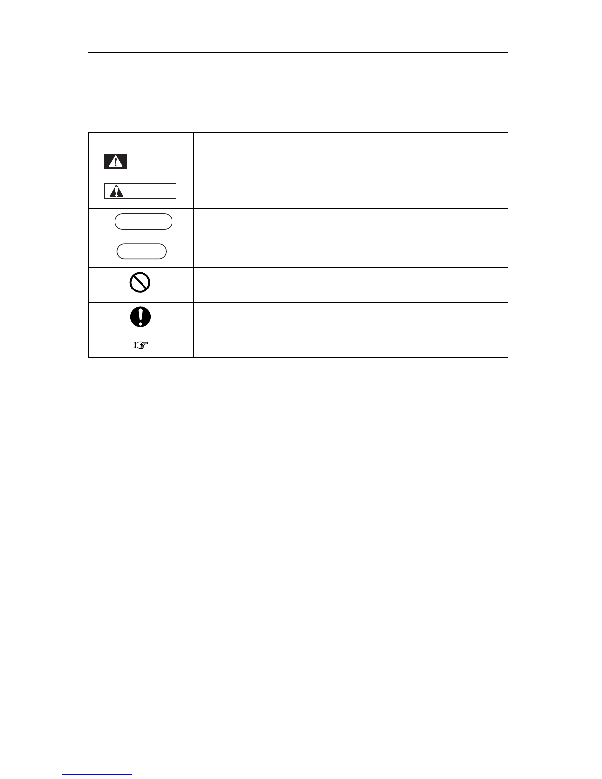
4.Manual Notation
This section explains general cautions that must be followed in order to use this printer safely.
Warning Meaning
Used for dangerous situations where death or serious injury may be caused.
Used for dangerous situations that may cause slight or medium injury, or when all or parts of
products are damaged.
It is used for special cautions and for information that needs to be emphasized.
Indicates useful tips for operating or understanding the printer.
Indicates "prohibited" operations.
Indicates required operations.
Indicates referrence pages in this manual.
WARNING
CAUTION
NOTE
NOTE
TIP
Page 7

VJ-1324 QUICK REFERENCE General Table Of Contents
GENERAL TABLE OF CONTENTS
(5)
1 Safety instructions
1.1 Types and meanings of warnings . . . . . . . . . . . . . . . . . . . . . . . . . . . . . . . 1-2
1.2 Important safety instructions. . . . . . . . . . . . . . . . . . . . . . . . . . . . . . . . . . . 1-3
1.3 Warning labels. . . . . . . . . . . . . . . . . . . . . . . . . . . . . . . . . . . . . . . . . . . . . . . 1-6
1.3.1 Handling the warning labels . . . . . . . . . . . . . . . . . . . . . . . . . . . . . . . . . . . . . . . 1-6
1.3.2 Location and type of warning labels . . . . . . . . . . . . . . . . . . . . . . . . . . . . . . . . . 1-6
1.4 Operating Instruction Labels . . . . . . . . . . . . . . . . . . . . . . . . . . . . . . . . . . . 1-8
1.4.1 Cautions on Handling the Operating Instruction Labels . . . . . . . . . . . . . . . . . . 1-8
1.4.2 Locations and Types of Operating Instruction Labels. . . . . . . . . . . . . . . . . . . . 1-8
2 Product overview
2.1 Names of parts and functions . . . . . . . . . . . . . . . . . . . . . . . . . . . . . . . . . . 2-2
2.1.1 Front section . . . . . . . . . . . . . . . . . . . . . . . . . . . . . . . . . . . . . . . . . . . . . . . . . . . 2-2
2.1.2 Rear section . . . . . . . . . . . . . . . . . . . . . . . . . . . . . . . . . . . . . . . . . . . . . . . . . . . 2-3
2.1.3 Operation panel . . . . . . . . . . . . . . . . . . . . . . . . . . . . . . . . . . . . . . . . . . . . . . . . 2-4
2.2 Printer status. . . . . . . . . . . . . . . . . . . . . . . . . . . . . . . . . . . . . . . . . . . . . . . . 2-7
2.2.1 Normal . . . . . . . . . . . . . . . . . . . . . . . . . . . . . . . . . . . . . . . . . . . . . . . . . . . . . . . 2-7
2.2.2 Setup menu display . . . . . . . . . . . . . . . . . . . . . . . . . . . . . . . . . . . . . . . . . . . . . 2-7
2.2.3 Changing printer status. . . . . . . . . . . . . . . . . . . . . . . . . . . . . . . . . . . . . . . . . . . 2-7
3 Basic usage
3.1 Print flow chart . . . . . . . . . . . . . . . . . . . . . . . . . . . . . . . . . . . . . . . . . . . . . . 3-2
3.2 Power cable connection. . . . . . . . . . . . . . . . . . . . . . . . . . . . . . . . . . . . . . . 3-4
3.3 Turning the power ON/OFF . . . . . . . . . . . . . . . . . . . . . . . . . . . . . . . . . . . . 3-8
3.3.1 Turning the power ON . . . . . . . . . . . . . . . . . . . . . . . . . . . . . . . . . . . . . . . . . . . 3-8
3.3.2 Turning the power OFF. . . . . . . . . . . . . . . . . . . . . . . . . . . . . . . . . . . . . . . . . . . 3-8
3.4 Installing ink cartridges . . . . . . . . . . . . . . . . . . . . . . . . . . . . . . . . . . . . . . 3-11
3.4.1 Installing 220ml ink cartridges . . . . . . . . . . . . . . . . . . . . . . . . . . . . . . . . . . . . 3-13
3.4.2 Installing high capacity pack adapters (optional) . . . . . . . . . . . . . . . . . . . . . . 3-17
3.4.3 When using the high capacity pack adapter for the printer
whose ink is charged for the first time 3-22
3.5 Loading media. . . . . . . . . . . . . . . . . . . . . . . . . . . . . . . . . . . . . . . . . . . . . . 3-23
3.5.1 Loading roll media . . . . . . . . . . . . . . . . . . . . . . . . . . . . . . . . . . . . . . . . . . . . . 3-23
3.5.2 Setting Roll Media. . . . . . . . . . . . . . . . . . . . . . . . . . . . . . . . . . . . . . . . . . . . . . 3-25
Page 8

General Table Of Contents VJ-1324 QUICK REFERENCE
(6)
3.6 Connecting the printer to PC. . . . . . . . . . . . . . . . . . . . . . . . . . . . . . . . . . .3-30
3.6.1 System requirements . . . . . . . . . . . . . . . . . . . . . . . . . . . . . . . . . . . . . . . . . . . 3-30
3.6.2 Preparing cables. . . . . . . . . . . . . . . . . . . . . . . . . . . . . . . . . . . . . . . . . . . . . . . 3-30
3.6.3 Connecting a network interface cable . . . . . . . . . . . . . . . . . . . . . . . . . . . . . . 3-30
3.7 Operating from the operation panel . . . . . . . . . . . . . . . . . . . . . . . . . . . . .3-32
3.7.1 Feeding media . . . . . . . . . . . . . . . . . . . . . . . . . . . . . . . . . . . . . . . . . . . . . . . . 3-32
3.7.2 Stopping printing operation. . . . . . . . . . . . . . . . . . . . . . . . . . . . . . . . . . . . . . . 3-32
3.7.3 Cutting media . . . . . . . . . . . . . . . . . . . . . . . . . . . . . . . . . . . . . . . . . . . . . . . . . 3-33
3.7.4 Cutting media manually . . . . . . . . . . . . . . . . . . . . . . . . . . . . . . . . . . . . . . . . . 3-34
3.7.5 Changing and confirming settings while printing . . . . . . . . . . . . . . . . . . . . . . 3-35
3.7.5.1 Procedure for changing and confirming settings while printing. . . . . . . . . . 3-35
3.7.5.2 Settings that can be changed or confirmed while printing. . . . . . . . . . . . . . 3-36
3.7.6 Pausing printing . . . . . . . . . . . . . . . . . . . . . . . . . . . . . . . . . . . . . . . . . . . . . . . 3-37
3.7.7 Start Printing during Warm up . . . . . . . . . . . . . . . . . . . . . . . . . . . . . . . . . . . . 3-38
3.8 Menu setups on the operation panel . . . . . . . . . . . . . . . . . . . . . . . . . . . .3-39
3.8.1 Menu setup procedure . . . . . . . . . . . . . . . . . . . . . . . . . . . . . . . . . . . . . . . . . . 3-39
3.8.2 Panel setup menu overview . . . . . . . . . . . . . . . . . . . . . . . . . . . . . . . . . . . . . . 3-41
3.9 Using spectrophotometer (SPECTROVUE VM-10) . . . . . . . . . . . . . . . . .3-42
4 Daily maintenance
4.1 Replacing consumable components . . . . . . . . . . . . . . . . . . . . . . . . . . . . .4-2
4.1.1 Replacing ink cartridges . . . . . . . . . . . . . . . . . . . . . . . . . . . . . . . . . . . . . . . . . . 4-2
4.1.2 Replacing Cutter. . . . . . . . . . . . . . . . . . . . . . . . . . . . . . . . . . . . . . . . . . . . . . . . 4-7
4.2 Cleaning the printer . . . . . . . . . . . . . . . . . . . . . . . . . . . . . . . . . . . . . . . . . .4-17
4.2.1 Cleaning the outer case . . . . . . . . . . . . . . . . . . . . . . . . . . . . . . . . . . . . . . . . . 4-17
4.2.2 Cleaning the inside of the printer . . . . . . . . . . . . . . . . . . . . . . . . . . . . . . . . . . 4-18
4.2.3 Head cleaning. . . . . . . . . . . . . . . . . . . . . . . . . . . . . . . . . . . . . . . . . . . . . . . . . 4-20
4.2.4 Cleaning the cleaning wiper . . . . . . . . . . . . . . . . . . . . . . . . . . . . . . . . . . . . . . 4-21
4.2.5 Cleaning around the print head . . . . . . . . . . . . . . . . . . . . . . . . . . . . . . . . . . . 4-27
4.3 Disposal of waste fluids. . . . . . . . . . . . . . . . . . . . . . . . . . . . . . . . . . . . . . .4-34
5 Troubleshooting
5.1 When you cannot generate graphics in the way you want. . . . . . . . . . . .5-2
5.1.1 Perform Head cleaning. . . . . . . . . . . . . . . . . . . . . . . . . . . . . . . . . . . . . . . . . . . 5-2
5.1.2 Adjust the print head. . . . . . . . . . . . . . . . . . . . . . . . . . . . . . . . . . . . . . . . . . . . . 5-3
5.1.3 Standard Adjust Print . . . . . . . . . . . . . . . . . . . . . . . . . . . . . . . . . . . . . . . . . . . . 5-3
5.1.3.1 Standard Confirmation Pattern . . . . . . . . . . . . . . . . . . . . . . . . . . . . . . . . . . . 5-4
5.1.3.2 Standard Rough Adjustment Pattern . . . . . . . . . . . . . . . . . . . . . . . . . . . . . . 5-8
5.1.3.3 Standard Micro Adjustment Pattern . . . . . . . . . . . . . . . . . . . . . . . . . . . . . . 5-11
5.1.4 Custom Adjustment Pattern . . . . . . . . . . . . . . . . . . . . . . . . . . . . . . . . . . . . . . 5-14
5.1.4.1 Custom Confirmation Pattern . . . . . . . . . . . . . . . . . . . . . . . . . . . . . . . . . . . 5-15
5.1.4.2 Custom Rough Adjustment Pattern. . . . . . . . . . . . . . . . . . . . . . . . . . . . . . .5-20
5.1.4.3 Custom Micro Adjustment Pattern . . . . . . . . . . . . . . . . . . . . . . . . . . . . . . . 5-24
5.1.4.3.1 Adj. PatternALL. . . . . . . . . . . . . . . . . . . . . . . . . . . . . . . . . . . . . . . . . 5-24
5.1.4.3.2 Each Adjust Patterns . . . . . . . . . . . . . . . . . . . . . . . . . . . . . . . . . . . . 5-27
Page 9

VJ-1324 QUICK REFERENCE General Table Of Contents
(7)
5.2 When media is jammed . . . . . . . . . . . . . . . . . . . . . . . . . . . . . . . . . . . . . . 5-30
5.3 Troubleshooting . . . . . . . . . . . . . . . . . . . . . . . . . . . . . . . . . . . . . . . . . . . . 5-33
5.3.1 Problems in installation and introduction . . . . . . . . . . . . . . . . . . . . . . . . . . . . 5-33
5.3.2 Cannot print at all . . . . . . . . . . . . . . . . . . . . . . . . . . . . . . . . . . . . . . . . . . . . . . 5-34
5.3.3 Media-related troubleshooting . . . . . . . . . . . . . . . . . . . . . . . . . . . . . . . . . . . . 5-35
5.3.4 Printing-related troubleshooting . . . . . . . . . . . . . . . . . . . . . . . . . . . . . . . . . . . 5-38
5.4 Error messages. . . . . . . . . . . . . . . . . . . . . . . . . . . . . . . . . . . . . . . . . . . . . 5-42
5.4.1 Status messages . . . . . . . . . . . . . . . . . . . . . . . . . . . . . . . . . . . . . . . . . . . . . . 5-42
5.5 Using Quick Reference and Operation Manual CD . . . . . . . . . . . . . . . . 5-44
5.5.1 System requirements . . . . . . . . . . . . . . . . . . . . . . . . . . . . . . . . . . . . . . . . . . . 5-44
5.5.2 How to view the file. . . . . . . . . . . . . . . . . . . . . . . . . . . . . . . . . . . . . . . . . . . . . 5-44
5.5.2.1 Setting Permissions for Active Content. . . . . . . . . . . . . . . . . . . . . . . . . . . . 5-45
Page 10

General Table Of Contents VJ-1324 QUICK REFERENCE
(8)
Page 11

VJ-1324 QUICK REFERENCE 1 Safety instructions
1-1
1 Safety instructions
This chapter explains the installation of this printer, warning terms that operators need to know, caution
items and warning labels on the printer main unit.
WARNING
• When installing and operating this printer, be sure to follow the directions and
warnings in this book.
Page 12
1 Safety instructions VJ-1324 QUICK REFERENCE
1-2
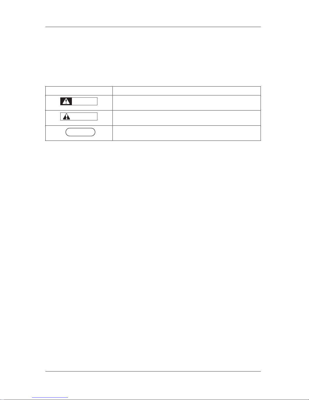
1.1 Types and meanings of warnings
The warnings in the Operation Manual and the warning labels attached to the printer are categorized into
three stages.
Understand the meanings of the following warning terms and follow the contents (instructions) in this
manual.
Warning M eanin g
Used for dangerous situations where death or serious injury may be caused.
Used for dangerous situations that may cause slight or medium injury, or when all or
parts of products are damaged.
Used for special cautions and for information that needs to be emphasized.
WARNING
CAUTION
NOTE
NOTE
Page 13
VJ-1324 QUICK REFERENCE 1 Safety instructions
1-3
1.2 Important safety instructions
This section explains general cautions that must be followed in order to use this printer safely.
Do not install this printer in the following places.
It may cause an injury if the printer falls down.
• On a shaky stand
• Slanting location
• Places where vibration of other machines etc. is transmitted
Do not step on this printer or place heavy things on top of it.
It may cause an injury if the printer falls down.
Do not block the vent by covering the printer with cloths, such as a blanket or tablecloth.
If the vent is blocked, heat may accumulate inside the printer and it may cause fire.
Do not install the printer where it is humid or dusty.
It could lead to an electric shock and fire.
Do not use a damaged power cable.
It could lead to an electric shock and fire.
Do not pull out or insert the power plug with a wet hand.
This could lead to an electric shock.
Do not connect an earth wire to the following places.
•Gas pipes
There is a possibility of ignition and explosion.
• Earth wire of telephone cables and lightning rods
Heavy current might flow whenever lightning strikes.
• Water pipe and faucet
The earth might not work if a plastic pipe is connected in the middle of the metal pipe.
Do not insert or drop metal or flammable objects into the printer through openings such as a vent.
It could lead to an electric shock or fire.
Do not spill flammable liquid on the platen.
This could lead to a fire.
Do not place any combustible materials on the platen while the heater is working.
There may be a risk of fire.
If foreign substances or liquids such as water entered the printer, do not use the printer as it is.
It could lead to an electric shock or fire.
Immediately turn OFF the power switch, disconnect the power plug from the electric socket, and contact your local
MUTOH dealer.
Wire the various cords as directed in the Operation Manual.
Mistaken wiring could cause fire.
Be sure to use the specified power cable.
Using power cables other than the specified can cause an electric shock or fire.
Make sure to use only the specified power supply (AC 100 V to 120 V or AC 220 V to 240 V).
If a power supply other than the specified voltage is used, it could cause an electric shock and fire.
WARNING
Page 14
1 Safety instructions VJ-1324 QUICK REFERENCE
1-4
Take power for the printer directly from the power socket (AC 100 V - 120 V or AC 220 V - 240 V).
Do not use multiple plugs on the same socket.
This could generate heat and might cause fire.
Be sure to use a dedicated power socket with earth wire for the power supply, and connect it to the earth wire.
If the earth wire is not connected, an electric shock or fire may occur.
The waste fluid from the printer falls under the category of waste oil (waste ink) of industrial waste (out of the 19
items of general waste from business activities).
You are obligated to properly dispose of waste fluid in compliance with Wastes Disposal and Public Cleansing Act
and local ordinances.
Delegate disposal to an industrial waste disposal contractor.
Pay attention to the following points when handling power cable.
• Do not tamper with the power cable.
• Do not put heavy objects on the power cable.
• Do not bend, twist or pull the power cable by force.
• Do not route the power cable near heating appliances.
Pay attention to the following points when handling the power supply plug.
Any mishandling of the power cable could cause a fire.
• Make sure that no foreign substances such as dust etc. are stuck to the power plug.
• Make sure that the power plug is firmly inserted to the edge of the power socket.
When handling ink cartridges, pay attention so that ink does not get into your eyes or stick to your skin.
If ink gets into your eyes or sticks to your skin, immediately wash it off with water.
Failing to do so might cause irritation or light inflammation of eyes.
In case of any abnormality, consult a physician immediately.
Do not disassemble ink cartridges.
If disassembled, there is a possibility that ink might come into contact with eyes or skin.
Do not operate the media loading lever during the initial operation or printing.
The print head portion may touch the pressurizing roller portion, and cause a malfunction.
Do not use volatile solvents such as thinner, benzene, or alcohol.
These solvents could cause damage to the paint.
Do not touch the media guide while printing.
The media guide becomes very hot and you could burn yourself.
Do not touch the media feed slot, platen, and media guide while the heater is working.
The media feed slot, platen, and media guide become very hot and you could burn yourself.
Be careful that no moisture enters the printer.
There is a possibility that the electric circuit inside the printer is short circuited.
Do not open covers attached using screws under any circumstances.
This may cause an electric shock or a malfunction.
When cleaning the cleaning wiper,
• Do not touch the cleaning wiper and head cap unit.
Head cleaning may not be performed correctly because of oil from your hands.
• Make sure to wipe the print head using the cleaning stick.
A wet cleaning stick may cause the print head to clog.
• Do not reuse the cleaning stick.
The attached dust, etc may damage the print head.
CAUTION
Page 15
VJ-1324 QUICK REFERENCE 1 Safety instructions
1-5
When cleaning around the print head,
• Do not touch the nozzles of the print head.
Doing so may damage the print head.
• Do not touch the tip of the cleaning stick.
The print head may be damaged because of oil from your hands.
• Never put water, etc on the tip of the cleaning stick.
Doing so may damage the print head.
• Do not reuse the cleaning stick.
The attached dust, etc may damage the print head.
Do not slant the printer, prop it against a wall or turn it upside down.
There is a possibility that ink inside the printer may leak.
Moreover, normal operation after shifting (to these positions) cannot be guaranteed.
Unpacking or moving this printer must be done by the following number of people.
• VJ-1324: more than three persons
Installing the dedicated stands on the printer must be done by the following number of people.
• VJ-1324: more than three persons
When installing the dedicated stands, make sure to turn OFF the printer and unplug the power cable.
There may be a risk of electric shock.
When you do not use the printer for a long period, make sure to pull out the power plug from the power socket for
safety.
Make sure to connect an earth wire to the earth connection that meets the following standards.
• Earth terminal of power socket
• Earth wire with copper plate which is buried at 650 mm or more, deep in the ground.
Before operation, make sure to read the Material Safety Data Sheet (MSDS).
Ventilate the workplace.
Not doing so may make you feel sick or may lead to a fire.
Right after printing, the media guide becomes very hot.
Allow the media guide to cool down before the next operation.
When loading the roll media, place it on a flat surface such as a desk.
If the roll media is loaded with the scroller up, the scroller may be damaged.
Pay attention to the following points when cutting roll media.
Mishandling the razor blade may cause a cut on your finger or hand.
• When you hold media, do not place your finger on the media cut groove.
• Move the razor blade along the media cut groove.
When cleaning the areas other than the wiper, make sure to turn OFF the power and unplug the power cable.
Move the printer maintaining a horizontal position.
Page 16
1 Safety instructions VJ-1324 QUICK REFERENCE
1-6
1.3 Warning labels
This section explains the handling of warning label, pasting location and types.
Warning labels are attached to parts of the printer that need special caution.
Understand the locations and the descriptions of the danger associated with each label before operating
the printer.
1.3.1 Handling the warning labels
When handling the warning labels, be careful about the following points.
NOTE
NOTE
• Check whether all the warning labels can be read.
If the letters or illustrations on the label are not clear, remove the dirt from the label.
• Use cloth, water and mild detergent for removing dirt from the warning label.
Avoid either organic solvents or gasoline.
• It is necessary to replace the labels if they are damaged, lost or illegible.
If the warning labels have to be replaced, contact your local MUTOH dealer.
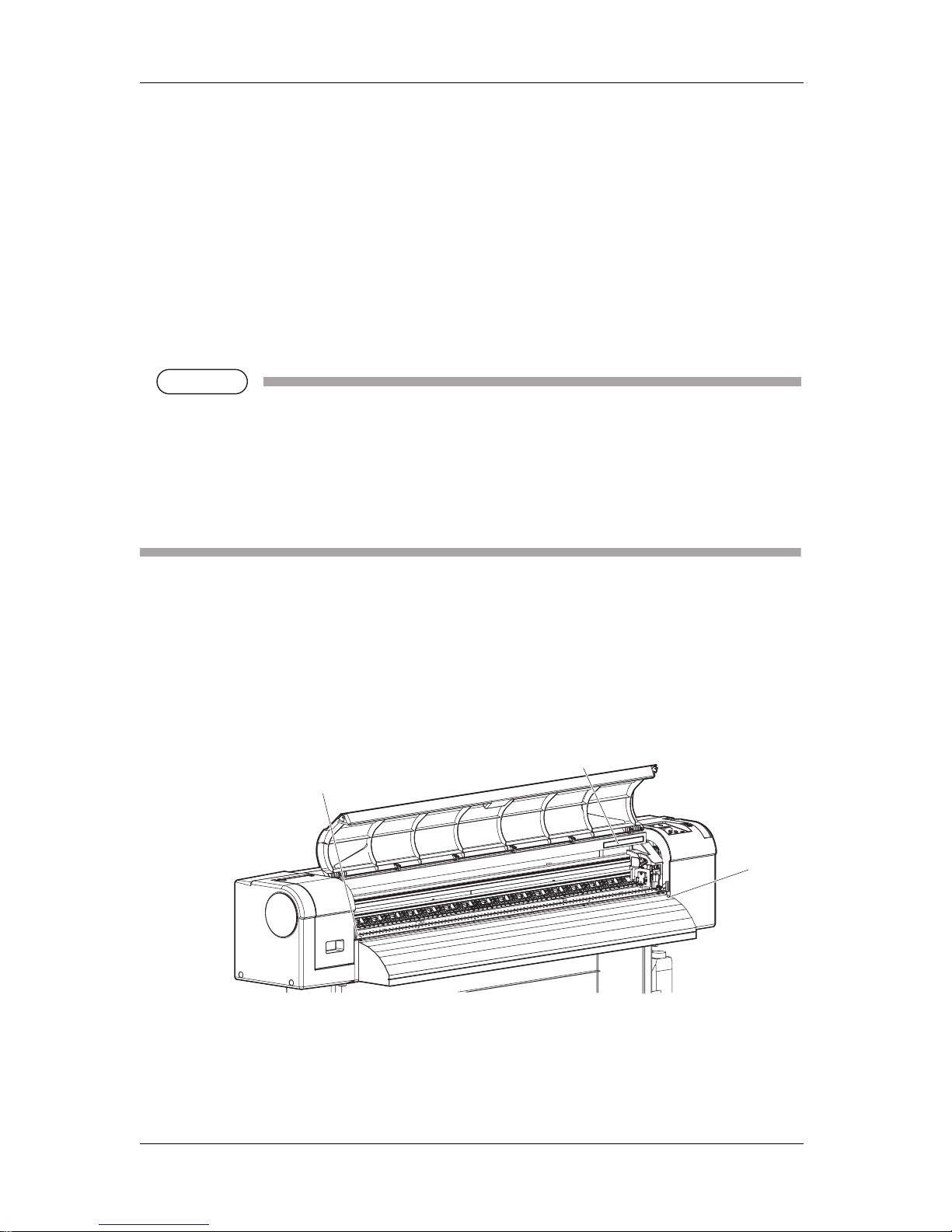
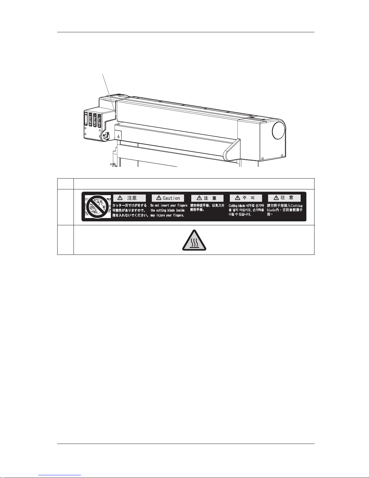
1.3.2 Location and type of warning labels
Pasting locations of the warning labels are shown in the following figure.
(1) Front
1
2
2
Page 17
VJ-1324 QUICK REFERENCE 1 Safety instructions
1-7
(2) Rear
No. Types of warning labels
1
2
2
Page 18
1 Safety instructions VJ-1324 QUICK REFERENCE
1-8
1.4 Operating Instruction Labels
This section explains the handling of operating instruction labels and their locations and types.
This printer has some operating instruction labels with simplified operation procedures where special
attention is required during operation.
Make sure to fully understand the locations and contents of the labels before operating the printer.
1.4.1 Cautions on Handling the Operating Instruction Labels
When handling the operating instruction labels, note the following.
NOTE
NOTE
• Check if all of the operating instruction labels can be read.
If the letters or illustrations on the label are not clear, remove the dirt from the label.
• When cleaning the operating instruction labels, use a cloth, water, and mild detergent.
Avoid either organic solvents or gasoline.
• It is necessary to replace the operating instruction labels if they are damaged, lost or unreadable.
If the operating instruction labels have to be replaced, contact your local MUTOH dealer.
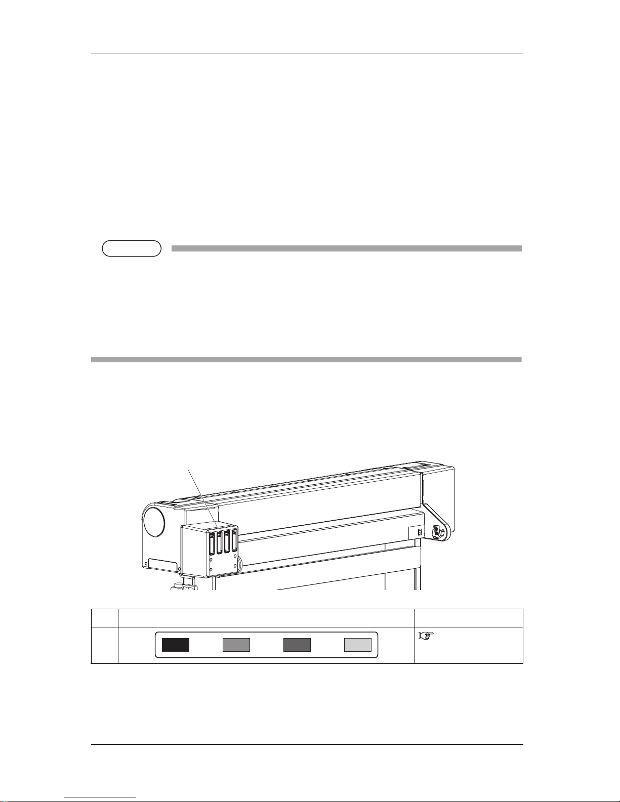
1.4.2 Locations and Types of Operating Instruction Labels
Locations of the operating instruction labels are shown in the following figure.
No. Types of the operating instruction labels Reference
1
4.1.1 Replacing ink
cartridges
1
Page 19

VJ-1324 QUICK REFERENCE 2 Product overview
2-1
2 Product overview
This chapter explains the features of the printer along with the names and functions of each part.
Page 20
2 Product overview VJ-1324 QUICK REFERENCE
2-2
2.1 Names of parts and functions
This section explains the names and functions of each part.
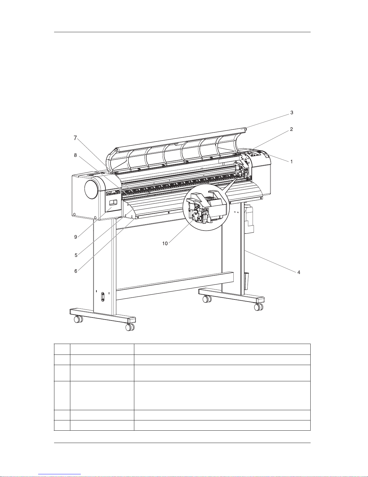
2.1.1 Front section
No. Name Function
1 Media loading lever Used for fixing or releasing media.
2 Operation panel Operation condition setting, printer display and various function settings are
performed.
3 Front cover Used for preventing a user from coming in contact with the driving mechanism during
the printer operation.
Opened and closed when media is set or jammed.
It is normally closed.
4 Stand Used when installing the printer on a flat floor.
5 Media guide Used for feeding media smoothly when the media is set or printed.
Page 21
VJ-1324 QUICK REFERENCE 2 Product overview
2-3
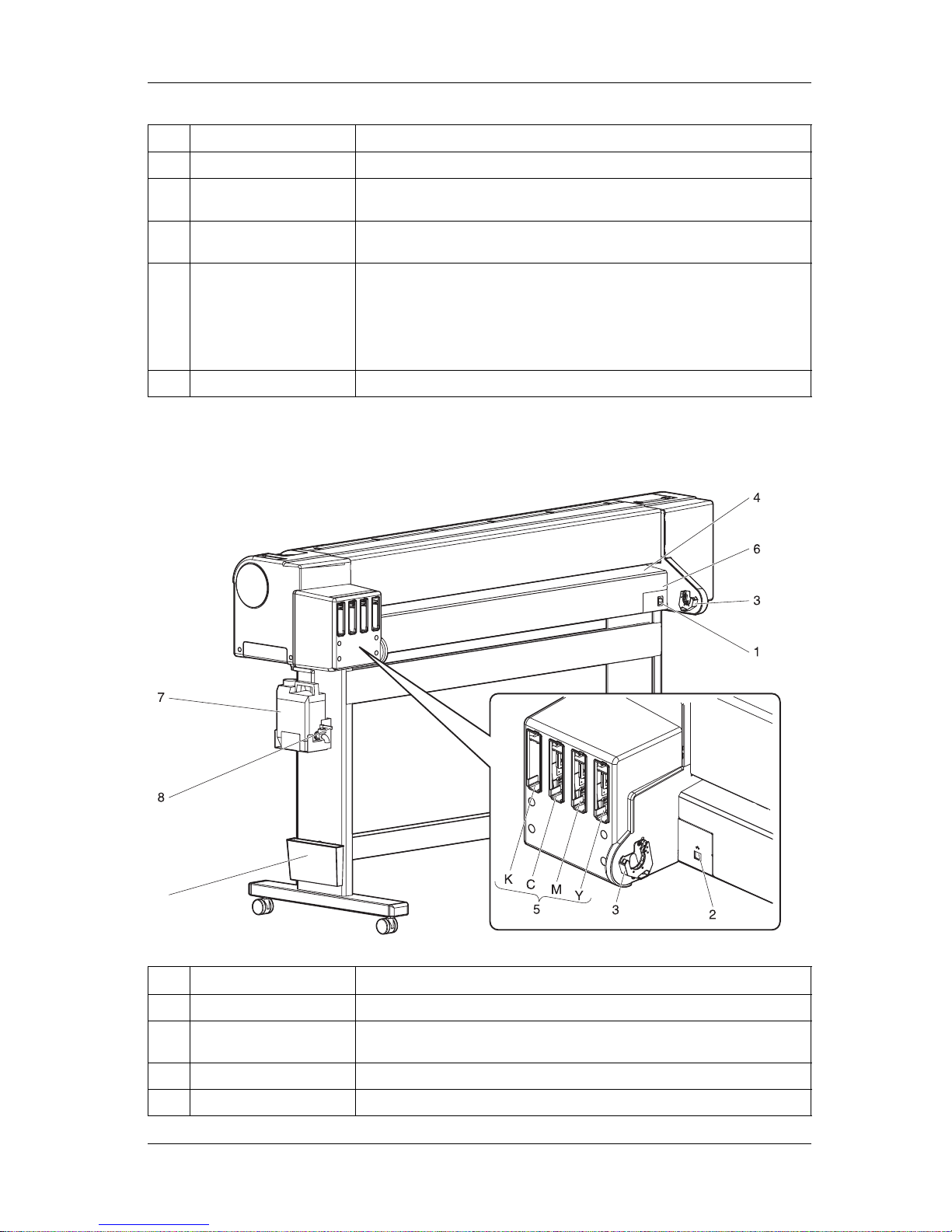
2.1.2 Rear section
6 Media cut groove Used to cut media straight.
7 Pressurizing rollers Installed inside of the front cover.
Press and hold the media when printing.
8 Platen Installed inside of the front cover.
Stabilizes the print side of the media.
9 Maintenance cover Used to prevent the user from touching the inner mechanical section.
Open and close in the following cases.
• When cleaning the cleaning wiper
• When cleaning around the print head.
• When replacing the cutter
It is normally closed.
10 Connector Used to install spectrophotometer (SPECTROVUE VM-10).
No. Name Function
1 AC inlet Used for connecting the power cable.
2 Network interface cable
connector
Connects a network interface cable.
3 Scroller holder Set the scroller here when using the roll media.
4 Media feed slot Used for feeding media.
No. Name Function
9
Page 22
2 Product overview VJ-1324 QUICK REFERENCE
2-4
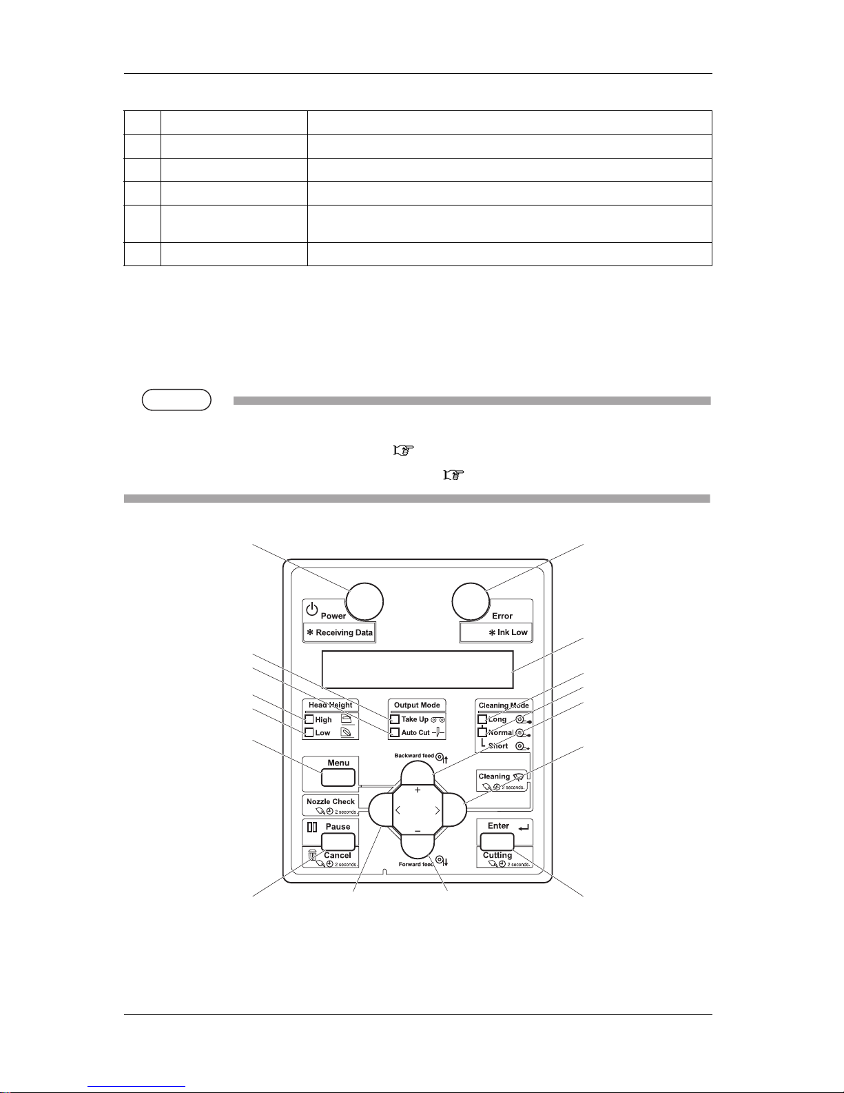
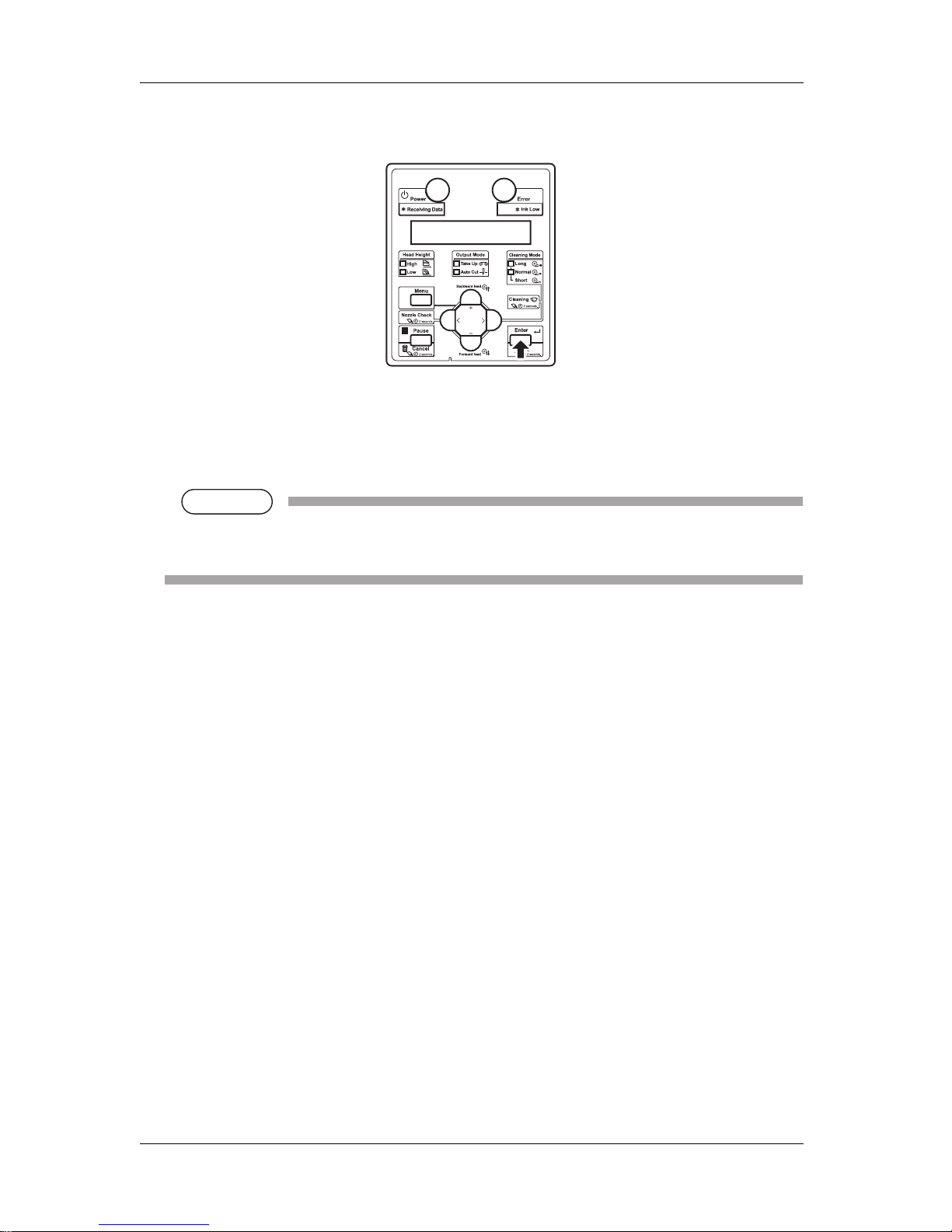
2.1.3 Operation panel
Used to set the operating conditions, to display the status of the printer, and to set various functions.
Names of each operation key and status display along with the functions are explained.
TIP
• Refer to the following for details regarding the operation method of the operation panel.
• When setting the menu from the operation panel: 3.8 Menu setups on the operation panel
• When performing various operations in the operation panel: 3.7 Operating from the operation panel
5 Ink cartridge slot Insert the ink cartridge.
6 Media guide Used for feeding media smoothly when the media is set or printed.
7 Waste fluid tank Used for collecting waste ink discharged from the printer.
8 Waste fluid valve Open and close when discharging the waste fluid from the waste fluid tank.
It is normally closed.
9 Book holder Quick reference etc can be stored.
No. Name Function
8, 9
3
15
17
16
6
5
11
12
1
13
14
10
27
4
Page 23
VJ-1324 QUICK REFERENCE 2 Product overview
2-5
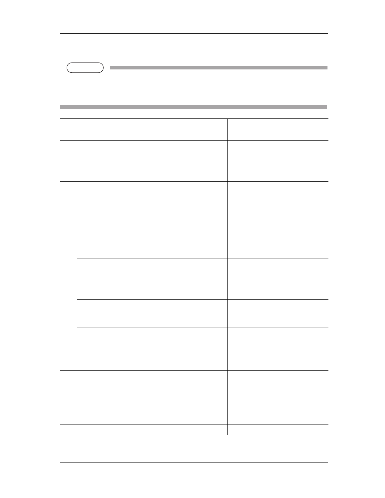
(1) Operation keys
NOTE
NOTE
• The operation keys are assigned with different functions and names depending on printer status
(Normal or Setup menu display).
For details about printer status, refer to "2.2 Printer status".
No. Name Normal Setup menu display
1 [Menu] key Shifts to the Setup menu. Shifts from Setup menu display to Normal.
2 [Enter] key Restarts printing when the printing is
suspended.
• Select the menu to be set, and shifts to the
next hierarchy.
• The setting is determined and saved.
[Cutting] key Cuts the media when pressed for more than
two seconds.
—
3 [Pause] key Pauses printing. —
[Cancel] key • When printing:
When pressed for more than two seconds,
forcefully terminates printing and deletes
one file of the remaining data.
• When receiving or analyzing data:
When pressed for more than two seconds,
deletes the data already received and
analyzed.
• Returns to the previous menu hierarchy.
Changes made in the setting are discarded.
• Shifts from Setup menu display to Normal.
4[<] key — —
[Nozzle Check] key Press and hold this key for two seconds or
more to perform Nozzle Check printing.
—
5 [>] key • Sets Cleaning Mode.
• The lamp of Cleaning Mode that you set
lights up in green.
Down the menu level in the directory tree.
[Cleaning] key When pressed for more than two seconds,
cleaning starts.
—
6[Backward↑] key Media is fed in the reverse direction. —
[+] key — • Changes to the previous item in the
displayed menu.
• The setting is changed to the reverse
direction.
• The numeric value is increased during
numerical input.
7[Forward↓] key Media is fed in the forward direction. —
[–] key — • Changes to the previous item in the
displayed setting.
• The setting is changed to the forward
direction.
• The numeric value is decreased during
numerical input.
8 [Power] key Turns the printer ON and OFF. Turns the printer ON and OFF.
Page 24
2 Product overview VJ-1324 QUICK REFERENCE
2-6
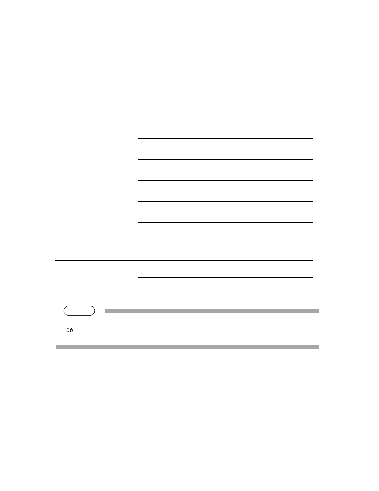
(2) Display section
TIP
• When an error requiring a restart (fatal malfunction for the printer operation) occurs, all lamps blink with an alarm.
"7.2.3 Error requiring restart" in the Operation Manual
If the error persists even when the malfunction is fixed, contact your local MUTOH dealer.
No. Name Color Status Description
9 Power lamp Blue Lamp ON Power ON.
Lamp blinks • Receiving and analyzing the data.
• Performing media initial operation.
Lamp OFF Power OFF.
10 Error lamp Orange Lamp ON An error has occurred.
Error content is displayed on the LCD.
Lamp blinks The remaining amount of ink is low.
Lamp OFF There is no error.
11 High lamp Green Lamp ON The head height is set to High.
Lamp OFF The head height is set to Low.
12 Low lamp Green Lamp ON The head height is set to Low.
Lamp OFF The head height is set to High.
13 Take Up lamp Green Lamp ON Media ejection mode is set to "Take Up".
Lamp OFF Media ejection mode is set to "Off" or "Auto Cut".
14 Auto Cut lamp Green Lamp ON Media ejection mode is set to "Auto Cut".
Lamp OFF Media ejection mode is set to "Off" or "Take Up".
15 Long lamp Green Lamp ON • Cleaning mode is set to Long.
• When the Normal lamp is also on, Cleaning mode is set to Short.
Lamp OFF Cleaning Mode is set to Normal.
16 Normal lamp Green Lamp ON • Cleaning Mode is set to Normal.
• When the Long lamp is also on, Cleaning mode is set to Short.
Lamp OFF Cleaning Mode is set to Long.
17 LCD display section — — Displays operation status of the printer or an error message.
Page 25

VJ-1324 QUICK REFERENCE 2 Product overview
2-7
2.2 Printer status
This section explains printer status.
2.2.1 Normal
Printing is possible when media is loaded.
The various functions for printing can be performed on the operation panel.
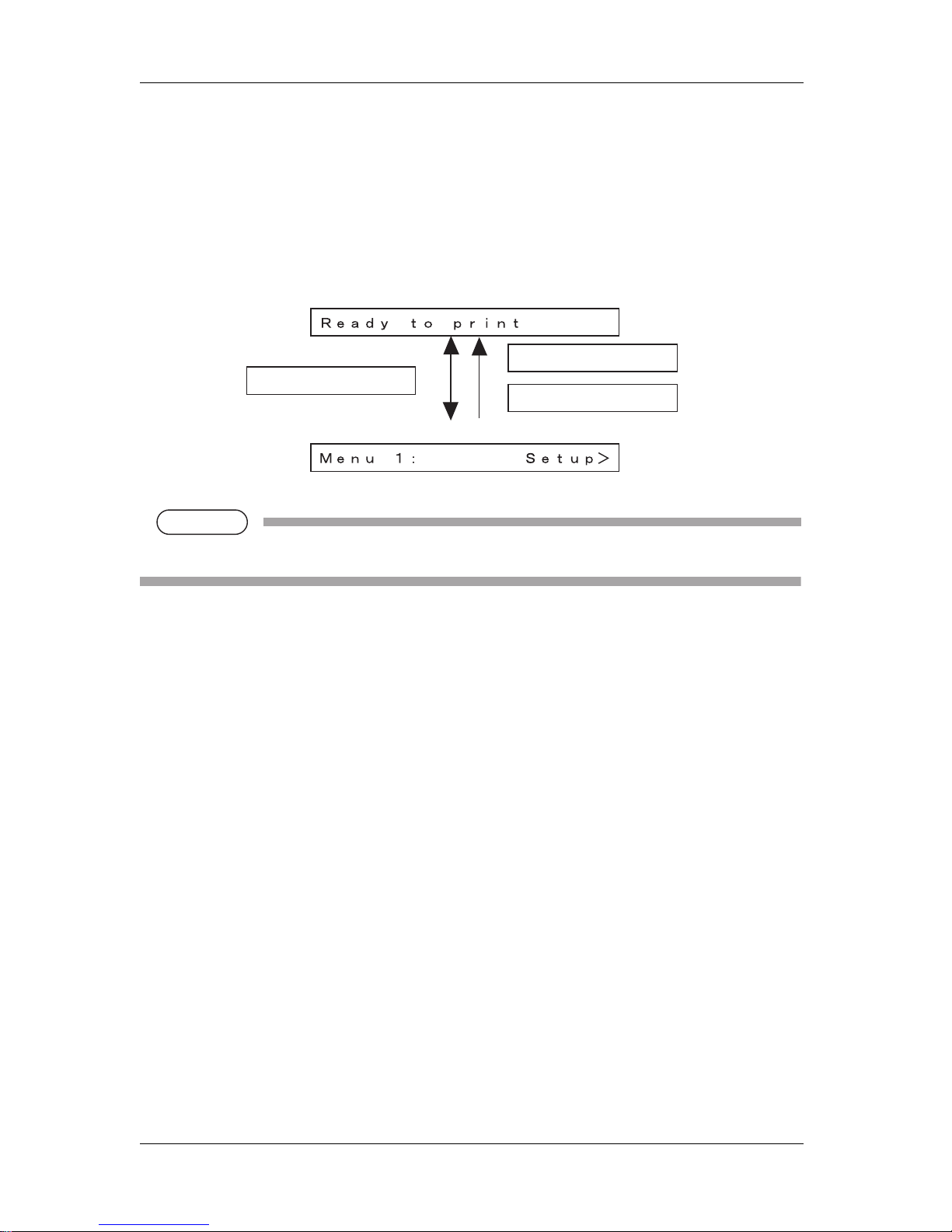
2.2.2 Setup menu display
Various settings regarding printing can be made from the operation panel.
The various functions for printing can be performed on the operation panel.
Display contents in the LCD monitor of the operation panel are as follows.
2.2.3 Changing printer status
Follow the procedure below and change printer status.
(1) Normal → Setup menu display
Press the [Menu] key on the operation panel when the printer is Normal.
• "Menu1: Setup>" is displayed on the operation panel and the display shifts to the Setup menu.
NOTE
NOTE
• For details regarding the Setup menu, refer to "3.8 Menu setups on the operation panel".
Page 26
2 Product overview VJ-1324 QUICK REFERENCE
2-8
(2) Setup menu display → Normal
When the printer is at the Setup menu display, perform either of the following operations to shift the
operation panel to the Normal display.
• Press the [Cancel] or [Menu] key on the operation panel.
• In the Setup menu, leave the keys untouched for three minutes.
NOTE
NOTE
• For details on Status message, refer to "5.4.1 Status messages".
Normal
Setup Menu Display
[Menu] key
[Cancel] key
Leave the printer
as it is for 3 minutes
Page 27

VJ-1324 QUICK REFERENCE 3 Basic usage
3-1
3 Basic usage
This chapter explains how to handle this printer.
Page 28
3 Basic usage VJ-1324 QUICK REFERENCE
3-2
3.1 Print flow chart
The following flow chart illustrates the procedure to perform printing with the printer.
Refer to each section as required.
WARNING
• Do not place any combustible materials on the platen while the heater is working.
There may be a risk of fire.
• Do not spill flammable liquid on the platen.
This could lead to a fire.
CAUTION
• Do not touch the media guide while printing.
The media guide becomes very hot and you could burn yourself.
• Do not touch the media feed slot, platen, and media guide while the heater is
working.
The media feed slot, platen, and media guide become very hot and you could burn
yourself.
• Ventilate the workplace.
Not doing so may make you feel sick or may lead to a fire.
1. Create print data.
Create print data with application software.
↓
2. Turn the power ON and set the media.
3.5 Loading media
"4.2 Media" in the Operation Manual
↓
3. Set up printing conditions.
3.8 Menu setups on the operation panel
↓
4. Perform the printing.
3.7 Operating from the operation panel
Page 29

VJ-1324 QUICK REFERENCE 3 Basic usage
3-3
NOTE
NOTE
• Do not open the front cover and maintenance cover during printing.
If the front cover/maintenance cover is opened, printing will be interrupted.
Printing restarts if you close the front cover/maintenance cover. However, the result of your print is
not guaranteed.
Page 30
3 Basic usage VJ-1324 QUICK REFERENCE
3-4
3.2 Power cable connection
This section explains power cable connection.
WARNING
• Be sure to use the specified power cable.
Using power cables other than the specified can cause an electric shock or fire.
• Use a power cord set which is compatible with the safety standards, power supply
voltage, and plug shape used in the country where this printer is used.
• Use a power cord set which is equipped with a protective earth, and securely
connect it to the outlet.
• Do not use a damaged power cable.
It could lead to an electric shock and fire.
CAUTION
• Pay attention to the following points when handling power cable.
• Do not tamper with the power cable.
• Do not put heavy objects on the power cable.
• Do not bend, twist or pull the power cable by force.
• Do not route the power cable near heating appliances.
NOTE
NOTE
• Contact your local MUTOH dealer in case of power cable damage.
Follow the procedure below to install the power cable.
Page 31

VJ-1324 QUICK REFERENCE 3 Basic usage
3-5
1. Make sure that the printer is turned OFF.
NOTE
NOTE
• The power is ON when the [Power] key of the operation panel is pressed in.
Press the key once again to turn OFF the power.
2. Connect the power cable to the AC inlet on the back of the printer.
No. Name
1AC inlet
2 Power cable
2
1
Page 32

3 Basic usage VJ-1324 QUICK REFERENCE
3-6
3. Insert the power cable plug firmly in the socket.
WARNING
• Do not pull out or insert the power plug with a wet hand.
This could lead to an electric shock.
• Make sure to use only the specified power supply (AC 100 V to 120 V or AC 220
V to 240 V).
If a power supply other than the specified voltage is used, it could cause an
electric shock and fire.
• Take power for the printer directly from the power socket (AC 100 V - 120 V or AC
220 V - 240 V).
Do not use multiple plugs on the same socket.
This could generate heat and might cause fire.
• Be sure to use a dedicated power socket with earth wire for the power supply,
and connect it to the earth wire.
If the earth wire is not connected, an electric shock or fire may occur.
• Do not connect an earth wire to the following places.
• Gas pipes
There is a possibility of ignition and explosion.
• Earth wire of telephone cables and lightning rods
Heavy current might flow whenever lightning strikes.
• Water pipe and faucet
The earth might not work if a plastic pipe is connected in the middle of the
metal pipe.
CAUTION
• Pay attention to the following points when handling the power supply plug.
Any mishandling of the power cable could cause a fire.
• Make sure that no foreign substances such as dust etc. are stuck to the power
plug.
• Make sure that the power plug is firmly inserted to the edge of the power
socket.
• When you do not use the printer for a long period, make sure to pull out the
power plug from the power socket for safety.
• Make sure to connect an earth wire to the earth connection that meets the
following standards.
• Earth terminal of power socket
• Earth wire with copper plate which is buried at 650 mm or more, deep in the
ground.
Page 33

VJ-1324 QUICK REFERENCE 3 Basic usage
3-7
NOTE
NOTE
• Contact the retail outlet of purchase if the earth connection cannot be established, or if the earth
connection is not given.
• When the power supply of the printer is ON, do not pull out the power cable from the power
socket.
Whenever the plug is pulled out from the power socket, allow one minute or more before
inserting the plug in the power socket again.
No. Name
1 Power plug
1
Page 34

3 Basic usage VJ-1324 QUICK REFERENCE
3-8
3.3 Turning the power ON/OFF
This section explains how to turn the printer ON/OFF.
3.3.1 Turning the power ON
Follow the procedure below to turn the power ON.
1. Press the [Power] key on the operation panel to turn ON the printer.
• Power lamp on the operation panel turns on (blue).
• The printer starts initial operation.
• When the initial operation is complete, the printer enters Normal.
NOTE
NOTE
• If there is a problem during the initial operation, a message is displayed on the operation panel
and the printer may stop operating.
If operation stops, refer to "5.3 Troubleshooting" and deal with the problem.
3.3.2 Turning the power OFF
Follow the procedure below to turn the printer OFF.
1. Verify the following regarding the operational condition of the product.
• Printing or other operations are not in progress.
• The operation panel display is Normal.
• The Low lamp on the operation panel lights up in green.
Page 35

VJ-1324 QUICK REFERENCE 3 Basic usage
3-9
NOTE
NOTE
• If the High lamp on the operation panel lights up in green, the head height is set to High.
Return the head height to Low before turning the power OFF.
"4.2.5.2 When returning the print head to the original position" in the Operation Manual
2. Press the [Power] key on the operation panel to turn OFF the printer.
• The Power lamp on the operation panel is turned off.
NOTE
NOTE
• If the operation panel is in the following status, the power is ON.
• The [Power] key is pressed in.
• Power lamp is on (blue).
Press the key once again to turn OFF the power.
• The printer starts the procedure to turn the power OFF.
• "Power Off" is displayed on the operation panel.
NOTE
NOTE
• If the head height is set to High, "Set Height to Low" is displayed on the operation panel and
the procedure to turn the power OFF stops.
To restart the procedure, return the head height to Low.
"4.2.5.2 When returning the print head to the original position" in the Operation Manual
• All the lamps on the operation panel and the LCD monitor are turned OFF.
• The printer automatically turns the power OFF.
Page 36

3 Basic usage VJ-1324 QUICK REFERENCE
3-10
NOTE
NOTE
• If there is a problem during turning OFF operation, a message is displayed on the operation
panel and the printer may stop operating.
If operation stops, refer to "5.3 Troubleshooting" and deal with the problem.
• After turning OFF the printer, wait for ten seconds or longer to turn it ON again.
3. Raise the media loading lever when the product is not used for a long time.
No. Name
1 Media loading lever
1
Page 37

VJ-1324 QUICK REFERENCE 3 Basic usage
3-11
3.4 Installing ink cartridges
This section describes the procedure to install the ink cartridges and high capacity pack adapter.
CAUTION
• Before operation, make sure to read the Material Safety Data Sheet (MSDS).
• When handling ink cartridges, pay attention so that ink does not get into your eyes
or stick to your skin.
If ink gets into your eyes or sticks to your skin, immediately wash it off with water.
Failing to do so might cause irritation or light inflammation of eyes.
In case of any abnormality, consult a physician immediately.
• Do not disassemble ink cartridges.
If disassembled, there is a possibility that ink might come into contact with eyes or
skin.
• Do not perform the following operations during ink filling.
• Do not turn OFF the printer.
• Do not unplug the power cable.
• Do not open the front cover.
• Do not raise the media loading lever.
Page 38

3 Basic usage VJ-1324 QUICK REFERENCE
3-12
NOTE
NOTE
• Do not share the ink cartridge once installed with another printer. The cartridge will not be usable
from that time onward.
• Use genuine ink cartridges or ink packs for charging.
This printer is designed to use genuine ink cartridges or ink packs .
If you use ink cartridges or ink packs which are not produced by the original manufacturer,
• Printing might become blurred and the end of the ink in the cartridge or pack might not be
detected correctly.
• Any problems caused by using an ink cartridge or pack other than those recommended above will
not be covered by the warranty, and repair expenses will be paid by the customer.
• For types and details of ink cartridges or ink packs and ink packs, contact your local MUTOH
dealer.
• Do not give ink cartridges or ink packs strong shakes.
Doing so may cause ink leakage.
• Do not disassemble ink cartridges or ink packs .
A disassembled ink cartridge cannot be used.
• Make sure to use the dedicated cleaning fluid (Model number: VJ-MSINK3-CL220/VJ-MSINK3CL1000).
• Before installing the ink cartridges or ink packs, shake it gently.
Doing so will preserve print quality.
• When an ink cartridges or ink packs is moved from a cold place to warm place, keep the ink
cartridges or ink packs for three hours or more in the new printing environment before printing.
• Do not insert or remove the ink cartridges or ink packs more than 10 times.
If the ink cartridge has been removed/inserted more than 10 times, it cannot be used even though
ink remains.
• The ink cartridges and ink packs for this printer have dedicated IC chip on them.
If removing/inserting the ink cartridges or ink packs and high capacity pack adapters (option) in the
following situations, the information within the IC chips may be damaged and the cartridges cannot
be used.
• During printing
• For several seconds after inserting the ink cartridge
Page 39

VJ-1324 QUICK REFERENCE 3 Basic usage
3-13
3.4.1 Installing 220ml ink cartridges
Follow the procedure below to install the 220ml ink cartridge.
1. Turn the printer ON.
• The printer starts the initializing operation.
• After the initial operation is compete, "Start Ink Charge – > E" is displayed on the operation
panel.
2. Press the [Enter] key on the operation panel.
• "Insert CleaningCart." is displayed on the operation panel.
3. Take out the cleaning cartridge from the bag.
Page 40

3 Basic usage VJ-1324 QUICK REFERENCE
3-14
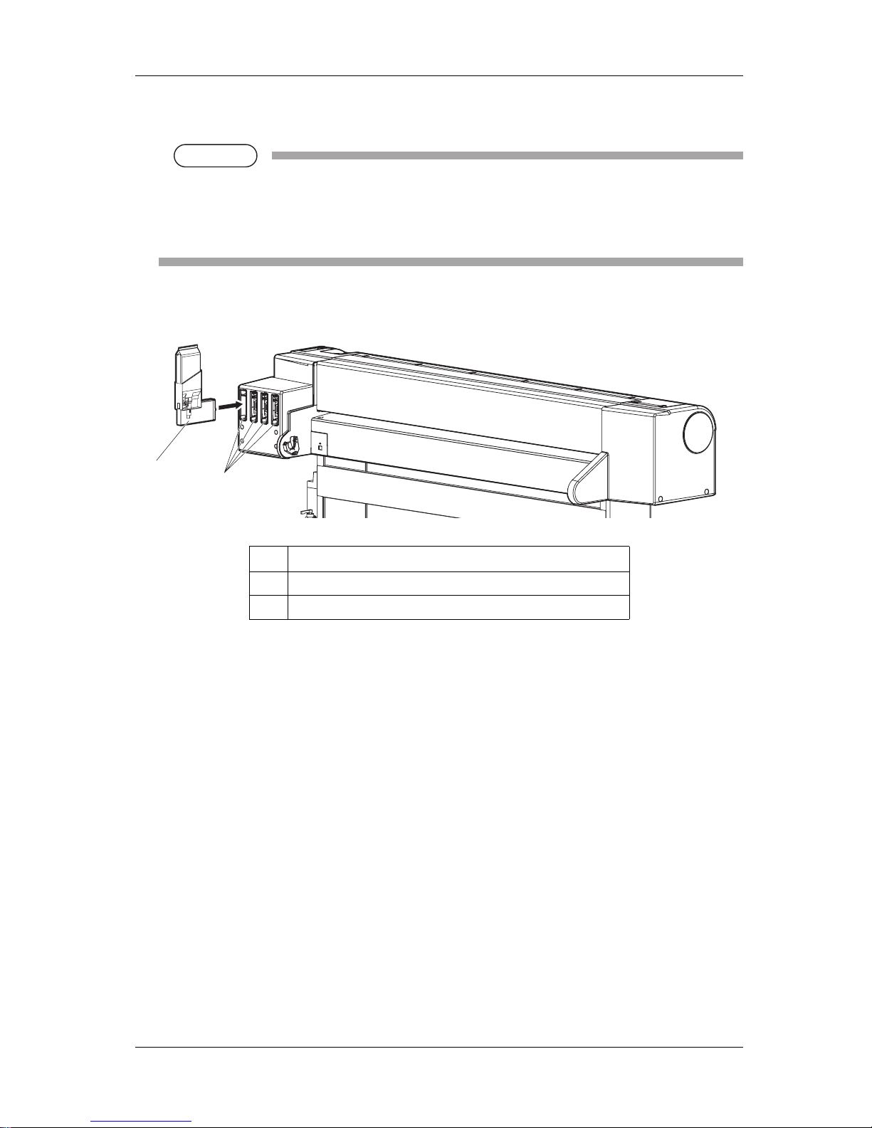
4. Set the cleaning cartridge to the ink cartridge slot.
• Keep mark of the cleaning cartridge facing up and insert towards the printer side.
• Insert the cleaning cartridge all the way to the end of the slot.
• When all cleaning cartridges are installed, "Busy-Washing" is displayed on the operation panel,
and the printer starts charging the cleaning fluid.
• When the cleaning fluid has been charged, "Remove Cartridges" is displayed on the operation
panel.
No. Name
1 Cleaning cartridge
2 Ink cartridge slots
1
2
Page 41

VJ-1324 QUICK REFERENCE 3 Basic usage
3-15
5. Remove all cleaning cartridges.
• "Busy-Washing" is displayed on the operation panel and the printer starts head cleaning.
• When head cleaning is complete, "Wash retry? No" is displayed on the operation panel.
NOTE
NOTE
• When performing head cleaning again before ink charge, press the [+] or [-] key on the
operation panel to select "Yes", and press the [Enter] key to perform head cleaning.
6. Press the [Enter] key on the operation panel.
• "Insert InkCartridges" is displayed on the operation panel.
No. Name
1 Cleaning cartridge
2 Ink cartridge slots
2
1
Page 42

3 Basic usage VJ-1324 QUICK REFERENCE
3-16
7. Take out the ink cartridge from the bag and shake it gently two to three times and insert it into the
printer.
• Make sure that the ink cartridges are inserted into the correct slots.
Match the mark in front of the slot and the color of the ink before inserting the ink cartridge.
• Keep mark of the ink cartridge facing up and insert towards the printer side.
• Insert the ink cartridge all the way to the end of the slot.
• "Ink Refill **%" is displayed on the operation panel and initial ink charge starts.
• Initial ink charge takes about four minutes.
Ink filling operation and pause operation are repeated during the initial ink charge.
• When "100%" is displayed, the initial ink charge is complete.
CAUTION
• Do not perform the following operations during ink filling. If filling is interrupted,
ink will be lost when filling is resumed.
• Do not turn OFF the printer.
• Do not unplug the power cable.
• Do not open the front cover.
• Do not open the maintenance cover.
• Do not raise the media loading lever.
• After the initial ink charge is complete, "Media End" is displayed on the operation panel.
No. Name
1 Ink cartridge
2 Ink cartridge slot K
3 Ink cartridge slot C
4 Ink cartridge slot M
5 Ink cartridge slot Y
2 3 4
5
1
Page 43

VJ-1324 QUICK REFERENCE 3 Basic usage
3-17
NOTE
NOTE
• If the printer perform the nozzle check printing immediately after initial ink charge is complete,
the following results may occur.
• Printed lines become blurred.
• The data is partially not printed.
In such cases, follow "4.2.3 Head cleaning" and refill a small amount of ink. Then, check the
printing result.
If there is no improvement in the print result even after refill a small amount of ink, leave the
printer unused for an hour or more. Then, refill a small amount of ink again and check the print
result.
If there is still no improvement, contact your local MUTOH dealer.
3.4.2 Installing high capacity pack adapters (optional)
Use the optional high capacity pack adapters to use the 1000ml ink packs on this printer.
Follow the procedure below to install the high capacity pack adapters.
1. Turn the printer ON.
• The printer starts the initializing operation.
• After the initial operation is compete, "Start Ink Charge – > E" is displayed on the operation
panel.
Page 44
3 Basic usage VJ-1324 QUICK REFERENCE
3-18
2. Press the [Enter] key on the operation panel.
• "Insert Cleaning cart." is displayed on the operation panel.
3. Take out the cleaning fluid packs (4 pieces) from the bag.
4. Install the cleaning fluid pack and smart chip card to the high capacity pack adapters.
NOTE
NOTE
• To install or remove the cleaning fluid pack and smart chip card to/from the high capacity pack
adapter, refer to the operation manual included with high capacity pack adapter.
Page 45
VJ-1324 QUICK REFERENCE 3 Basic usage
3-19
5. Insert the high capacity pack adapters into the ink cartridge slot.
NOTE
NOTE
• Do not insert the high capacity pack adapter into the ink cartridge slot without a cleaning fluid
pack attached.
The information of the remaining amount will be overwritten and the cleaning fluid pack will
not be usable.
• Insert the high capacity pack adapter all the way to the end of the slot.
• When all high capacity pack adapters are installed, "Busy-Washing" is displayed on the
operation panel, and the printer starts charging the cleaning fluid.
• When the cleaning fluid has been charged, "Remove Cartridges" is displayed on the operation
panel.
No. Name
1 High capacity pack adapter
2 Ink cartridge slots
1
2
Page 46

3 Basic usage VJ-1324 QUICK REFERENCE
3-20
6. Remove all the high capacity pack adapters.
• "Busy-Washing" is displayed on the operation panel and the printer starts head cleaning.
• When head cleaning is complete, "Wash retry? No" is displayed on the operation panel.
NOTE
NOTE
Do not remove only cleaning fluid pack while high capacity pack adapter is installed on the
printer. The information of the remaining smart chip card will be rewritten and the cleaning fluid
pack will not be usable.
7. Press the [Enter] key on the operation panel.
• "Insert InkCartridges" is displayed on the operation panel.
No. Name
1 High capacity pack adapter
1
Page 47

VJ-1324 QUICK REFERENCE 3 Basic usage
3-21
8. Remove the cleaning fluid pack and smart chip card from the high capacity pack adapter.
NOTE
NOTE
• When there is remaining cleaning fluid pack and smart chip card, clarify the corresponding
pack and card, and store it as a set.
9. Install the ink pack and smart chip card to high capacity pack adapter.
10. Shake the high capacity pack adapter gently two to three times and insert it to the slot.
NOTE
NOTE
• Do not insert the high capacity pack adapter into the ink cartridge slot without a cleaning fluid
pack attached.
The information of the remaining amount will be overwritten and the cleaning fluid pack will
not be usable.
• Insert the high capacity pack adapter all the way to the end of the slot.
• When a high capacity pack adapter is installed, "Ink Refill **%" is displayed on the operation
panel and ink replenishment starts.
• Initial filling takes about four minutes.
Ink filling operation and pause operation are repeated during the ink replenishment.
• When "100%" is displayed, the ink replenishment is complete.
No. Name
1 High capacity pack adapter
2 Ink cartridge slot K
3 Ink cartridge slot C
4 Ink cartridge slot M
5 Ink cartridge slot Y
1
5
4
3
2
Page 48

3 Basic usage VJ-1324 QUICK REFERENCE
3-22
CAUTION
• Do not perform the following operations during ink filling. If filling is interrupted,
ink will be lost when filling is resumed.
• Do not turn OFF the power of the printer.
• Do not unplug the power cable of the printer.
• Do not open the front cover.
• Do not open the maintenance cover.
• Do not raise the media loading lever.
• After the ink replenishment is complete, "Media End" is displayed on the operation panel.
NOTE
NOTE
• If the printer performs the nozzle check printing immediately after initial ink replenishment is
complete, the following results may occur.
• Printed lines become blurred.
• The data is partially not printed.
In such cases, follow "4.2.3 Head cleaning" and refill a small amount of ink. Then, check the
printing result.
If there is no improvement in the print result even after refill a small amount of ink, leave the
printer unused for an hour or more. Then, refill a small amount of ink again and check the print
result.
If there is still no improvement, contact your local MUTOH dealer.
3.4.3 When using the high capacity pack adapter for the printer
whose ink is charged for the first time
The air inside the high capacity pack adapter goes into the printer ink tube and may cause nozzle
clogging. Make sure to perform initial ink charge from the Cleaning menu in the following case.
• When using the high capacity pack adapter for the printer whose ink is charged for the first time
• When replacing the high capacity pack adapter’s adapter itself with a new one
"5.3 Cleaning menu" in the Operation Manual
Page 49

VJ-1324 QUICK REFERENCE 3 Basic usage
3-23
3.5 Loading media
This section explains how to load and set media, and settings for each media type.
NOTE
NOTE
• Refer to the following for details about handling media.
"4.2 Media" in the Operation Manual
• For details of the recommended media, contact your local MUTOH dealer.
3.5.1 Loading roll media
This section describes the procedure to load the roll media.
To load the roll media, use the scroller included with the printer.
NOTE
NOTE
• The following roll media can be loaded on the scroller included with the printer.
• Media tube with a diameter of three inches: Less than 150mm in outer diameter, less than 19kg
in weight
• Media tube with a diameter of two inches: Less than 150mm in outer diameter, less than 19kg in
weight
Follow the procedure below to load the roll media.
CAUTION
• When loading the roll media, place it on a flat surface such as a desk.
If the roll media is loaded with the scroller up, the scroller may be damaged.
Page 50

3 Basic usage VJ-1324 QUICK REFERENCE
3-24
1. When using the roll media with the media tube width of two inches, remove the attachments for
three-inch media from the movable media stopper and fixed media stopper.
2. To set the roll media on the scroller, make sure that the paper is rolled counter-clockwise when seen
from the fixed media stopper.
3. Insert the roll media all the way till its core touches the right edge of the fixed media stopper.
No. Name
1 Movable media stopper
2 Fixed media stopper
3 Attachments for three-inch media
No. Name
1 Fixed media stopper
2 Roll media
2
3
3
1
1
2
Page 51

VJ-1324 QUICK REFERENCE 3 Basic usage
3-25
4. Attach the movable media stopper firmly to the core of the roll media.
5. Set the scroller on the holder with the fixed media stopper on the ink cartridge slot side.
3.5.2 Setting Roll Media
This section explains how to set the roll media.
Follow the procedure below to set the roll media.
No. Name
1 Movable media stopper
2 Roll media
No. Name
1 Scroller
2 Fixed media stopper
3 Ink cartridge slots
4 Scroller holder
2
1
Page 52

3 Basic usage VJ-1324 QUICK REFERENCE
3-26
1. Turn the printer ON.
CAUTION
• Do not operate the media loading lever during the initial operation or printing.
The print head portion may touch the pressurizing roller portion, and cause a
malfunction.
• The printer starts the initializing operation.
• "Media End" is displayed on the operation panel.
2. Raise the media loading lever.
• "Lever Up" is displayed on the operation panel.
No. Name
1 Media loading lever
1
Page 53

VJ-1324 QUICK REFERENCE 3 Basic usage
3-27
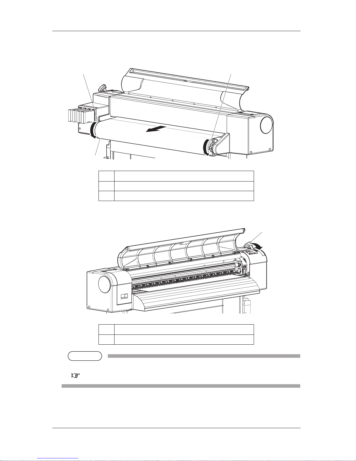
3. Set the roll media to the media feed slot.
NOTE
NOTE
• If the end of the roll media is not wound tightly, wind it tightly again, and then load it.
4. Open the front cover to pull out the roll media.
No. Name
1 Roll media
2 Media feed slot
No. Name
1 Front cover
2 Roll media
1
2
2
1
Page 54
3 Basic usage VJ-1324 QUICK REFERENCE
3-28
5. While holding the edge of the media, rewind the roll media a little by turning the scroller by hand
and eliminate any slack or slant.
6. Lower the media loading lever.
NOTE
NOTE
• When loading the new roll media, cut the front edge of the media if it is not straight.
3.7.3 Cutting media
No. Name
1 Roll media
2 Scroller
No. Name
1 Media loading lever
1
2
2
1
Page 55

VJ-1324 QUICK REFERENCE 3 Basic usage
3-29
7. Close the front cover.
• The User type setup menu is displayed on the operation panel.
TIP
• To change the media type, follow "3.4.3 Setting the User Type Setting" in the Operation Manual and set the
media type.
No. Name
1 Front cover
1
Page 56

3 Basic usage VJ-1324 QUICK REFERENCE
3-30
3.6 Connecting the printer to PC
This section explains how to connect the printer and a PC.
3.6.1 System requirements
The following are the system requirements for this printer.
NOTE
NOTE
• The required memory varies depending on the application software or the print data type.
• A large hard disk and memory are recommended.
3.6.2 Preparing cables
The printer is equipped with a network interface for connecting with a PC.
You need a network interface cable to connect a PC with this printer.
Prepare the cable depending on the PC that it will be connected to.
TIP
• About connecting a network interface cable, refer to "3.6.3 Connecting a network interface cable".
• For recommended cable specifications, refer to " 8.2 Interface specification" in the Operation Manual.
3.6.3 Connecting a network interface cable
This section explains how to connect a network interface cable.
Follow the procedure below to connect this printer to your PC.
1. Turn OFF both the printer and PC.
Operating system Windows 2000 Professional, Windows XP Professional, Windows Vista Business, Windows
7 Professional, and Windows Server 2003
CPU Pentium 4 processor 2.5GHz or more
Memory (RAM) Requires 1GB or more
Hard disk free space Requires 20GB or more
Page 57
VJ-1324 QUICK REFERENCE 3 Basic usage
3-31
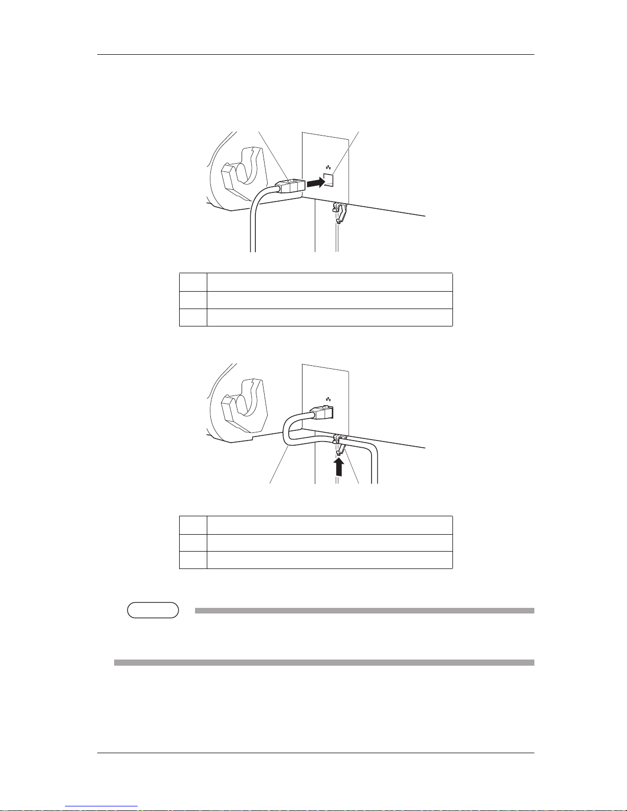
2. Insert the network interface cable into the network interface connector located on the back of the
printer.
3. Fix the network interface cable to the cable clamp.
4. Connect the other connector of the network interface cable to your PC.
TIP
• About connecting to your PC, refer to the operation manual included with the PC.
• For network setting on the side of the printer, refer to "3.8.2 Panel setup menu overview".
No. Name
1 Network interface cable
2 Network interface cable connector
No. Name
1 Network interface cable
2 Cable clamp
1
2
1
2
Page 58

3 Basic usage VJ-1324 QUICK REFERENCE
3-32
3.7 Operating from the operation panel
This section explains various functions that can be operated from the operation panel.
TIP
• For names and functions of each key, refer to "2.1.3 Operation panel".
3.7.1 Feeding media
You can feed the roll media at a position that you want.
Follow the procedure below to feed media.
1. Confirm that the operation panel is Normal.
2. Make sure that the media loading lever is lowered.
3. Press the [Forward↓] key or the [Backward↑] key on the operation panel.
• Media is fed forward or backward.
4. Release the [Backward↑] key or [Forward↓] key on the operation panel after feeding media to the
desired position.
3.7.2 Stopping printing operation
If you want to stop printing for some reason, operate as follows.
1. Stop sending printing data from the computer to the printer.
Page 59

VJ-1324 QUICK REFERENCE 3 Basic usage
3-33
2. Press the [Cancel] key on the operation panel for two seconds.
• The printer operates as follows.
NOTE
NOTE
• If a large amount of data is saved on the printer, the operation panel may not return to Normal by a
single [Cancel] key operation.
In such cases, wait for a few seconds and press the [Cancel] key again.
3.7.3 Cutting media
If Media ejection mode is set to "Cut", the printer cuts the media automatically after printing.
"5.1.6 Output Mode menu" in the Operation Manual
If you press the [Cutting] key on the operation panel more than two seconds while the operation panel is
Normal, you can cut the media at the desired position.
Follow the procedure below to cut the roll media.
1. Confirm that the operation panel is Normal.
Printer status Operation with the [Cancel] key pressed for two seconds
During printing Terminates the printing, and deletes one data remaining in the printer.
Receiving data/analyzing data Deletes the data already received and converted.
Page 60

3 Basic usage VJ-1324 QUICK REFERENCE
3-34
2. Press the [Cutting] key on the operation panel for more than two seconds.
• The printer feeds the roll media to the length of the margin and cuts the media.
NOTE
NOTE
• When loading the new roll media, cut the front edge of the media if it is not straight.
• The cutter is a consumable component.
Replace it periodically.
4.1.2 Replacing Cutter
• When the media detection is set to "Off", the media cannot be cut automatically.
3.7.4 Cutting media manually
This section explains how to cut the roll media manually.
CAUTION
• Right after printing, the media guide becomes very hot.
Allow the media guide to cool down before the next operation.
Follow the procedure below to cut the roll media.
1. Verify the following regarding the operational condition of the product.
• Printing or other operations are not in progress.
• The operation panel display is Normal.
2. To change the position to cut the roll media, refer to "3.7.1 Feeding media" and advance the roll
media to the desired cut position.
Page 61

VJ-1324 QUICK REFERENCE 3 Basic usage
3-35
3. Place a razor blade on the media cut groove on the media guide, and cut the roll media.
CAUTION
• Pay attention to the following points when cutting roll media.
Mishandling the razor blade may cause a cut on your finger or hand.
• When you hold media, do not place your finger on the media cut groove.
• Move the razor blade along the media cut groove.
• The procedure for cutting the roll media is complete.
NOTE
NOTE
• When loading the new roll media, cut the front edge of the media if it is not straight.
3.7.5 Changing and confirming settings while printing
While the printer is operating, you can change or confirm settings for the Panel setup menu.
3.7.5.1 Procedure for changing and confirming settings while printing
Follow the procedure below to change or confirm settings for the Panel setup menu.
No. Name
1 Media guide
2 Media cut groove
3 Razor blade
2
1
3
Page 62

3 Basic usage VJ-1324 QUICK REFERENCE
3-36
1. Confirm that the printer is in one of the following conditions.
• Receiving data
• Analyzing data
• Printing data
2. Press the [Menu] key on the operation panel.
• "Menu5: Temperature" is displayed on the operation panel.
3. Press the [+] key or [–] key to change or confirm settings.
NOTE
NOTE
• For the setting items whose settings can be changed or confirmed, refer to "3.7.5.2 Settings that
can be changed or confirmed while printing".
3.7.5.2 Settings that can be changed or confirmed while printing
NOTE
NOTE
• When you change a setting during operation, be sure to select "Backup" to save the setting that you
changed.
If the printer returns to Normal without "Backup" being selected, the changed setting is not saved.
Setup item Setting Description
Temperature Pre Checks the current temperature of the pre-heater.
Platen Checks the current temperature of the platen heater.
Dryer Checks the current temperature of the dryer.
Pre heater Off / 30 °C to 50 °C Changes the temperature of the pre-heater.
Platen heater Off / 30 °C to 50 °C Changes the temperature of the platen heater.
Dryer Off / 30 °C to 50 °C Changes the temperature of the dryer.
Page 63

VJ-1324 QUICK REFERENCE 3 Basic usage
3-37
3.7.6 Pausing printing
It is possible to pause to print during printing.
Follow the procedure below to pause or restart printing.
NOTE
NOTE
• If the printing is paused, the print quality will not be guaranteed.
1. Check that the printer is in operating.
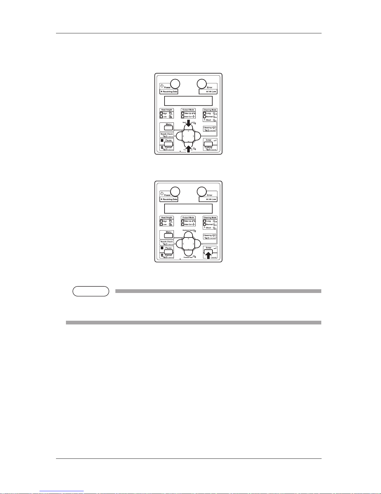
2. Press the [Pause] key on the operation panel.
• The printer pauses printing.
• "PrintRestart -> ENTER" is displayed on the operation panel.
PF Adjust -5.00%~0.00~5.00% Change the feed adjustment value.
Backup — • [Enter] key: Save the changed setting.
— • [Cancel] key: The printer returns to Normal.
Setup item Setting Description
Page 64

3 Basic usage VJ-1324 QUICK REFERENCE
3-38
3. To restart printing, press the [Enter] key on the operation panel.
• The printer restarts printing.
3.7.7 Start Printing during Warm up
You can start printing even when the heater temperature has not reached the preset value while the printer
is being warmed up.
NOTE
NOTE
• Even when printing is started during warm up, the printer continues to be warmed up until the preset
temperature has been reached.
• When printing is started during warm up, the print quality is not guaranteed.
1. Check if the printer is the printer is being warmed up.
• "Warming Up" is displayed on the operation panel.
2. Send the data.
• "Warming Up" "Skip -> ENTER" is displayed on the operation panel.
3. When printing during warm up, press the [Enter] key on the operation panel.
• The printer starts printing.
Page 65

VJ-1324 QUICK REFERENCE 3 Basic usage
3-39
3.8 Menu setups on the operation panel
3.8.1 Menu setup procedure
Follow the procedure below to configure each setup menu.
1. Confirm that the operation panel is Normal.
2. Press the [Menu] key on the operation panel.
• "Menu1: Setup>" is displayed on the operation panel.
• The operation panel shifts to the Setup menu display.
3. Press the [+] key or [–] key on the operation panel to select a setup item and press the [Enter] key.
• The settings will be confirmed.
• When setup items have a submenu, the display shifts to the next menu.
NOTE
NOTE
• When a setup item has a submenu, ">" is displayed on the right end of the LCD monitor of the
operation panel.
Page 66
3 Basic usage VJ-1324 QUICK REFERENCE
3-40
4. The setting in the blinking part on the LCD monitor of the operation panel can be changed.
Press the [+] key or [-] key to change the set value.
5. To save the changed setting, press the [Enter] key on the operation panel.
• The setting is saved and the next setup item is displayed.
NOTE
NOTE
• If you press the [Cancel] key, [+] key or [–] key without pressing [Enter] key after changing a
setting, the change will not be saved.
Page 67

VJ-1324 QUICK REFERENCE 3 Basic usage
3-41
6. Press the [Cancel] key on the operation panel to exit from the setup.
• The previous setup menu is displayed.
• When the main menu is displayed, the screen turns to Normal.
3.8.2 Panel setup menu overview
This section explains the Panel setup menu of the printer.
There are the following items in the Panel setup menu.
TIP
• For details regarding the Setup menu, refer to "5 Panel setup menu" in the Operation Manual.
Setup item Description
Setup menu Various settings of the printer are configured.
Test Print menu Performs nozzle check of the print head and setup list.
Cleaning menu Performs head cleaning.
Menu Option menu Sets up the contents of the Setup menu.
Version menu Displays the versions of the firmware.
Sleep Mode menu Sleep mode settings are configured.
Display menu Sets the language and unit displayed on the LCD monitor of the operation panel.
Page 68

3 Basic usage VJ-1324 QUICK REFERENCE
3-42
3.9 Using spectrophotometer (SPECTROVUE VM-
10)
The optional spectrophotometer (SPECTROVUE VM-10) can be attached to print and measure the color
target. Performing color calibration or profiling of the printer by using RIP software compatible with
SPECTROVUE VM-10 enables printing with more accurate colors.
For more information about the option, contact your local MUTOH dealer.
Follow the procedure below.
NOTE
NOTE
• Do not install the printer in a place that is subject to strong light (sunlight, etc).
Getting strong light on the color measurement may affect the measurement accuracy.
• To use SPECTROVUE VM-10, the printer setting must be as follows.
Make sure the setting before use.
• Media detection: Top & Width or Width
• Output mode: Off or Auto Cut
"5.1.6 Output Mode menu" in the Operation Manual
• When the color target is printed on the translucent or colored media, or the media with patterned
indented surfaces, color measurement may not be accurate.
• For details on spectrophotometer (SPECTROVUE VM-10), refer to its operation manual as well.
• When measuring colors, make sure that the color target is dry. If it is not dry enough, the ink may
adhere to the pressurizing rollers of the printer.
1. Connect the printer and computer.
3.6 Connecting the printer to PC
2. Turn the printer ON.
3. Set the media.
3.5 Loading media
4. Set the user type setting.
"3.4.3 Setting the User Type Setting" in the Operation Manual
• When the user type setting and media initial operation are complete, "Ready to Print" is
displayed on the operation panel.
Page 69

VJ-1324 QUICK REFERENCE 3 Basic usage
3-43
5. Start RIP software to print and measure the color target.
NOTE
NOTE
• For the setting and operations of the RIP software, refer to its operation manual.
• The printer starts printing the color target.
• "Printing" is displayed on the operation panel.
• After printing is complete, "Attaching instrument [ENTER]" is displayed on the operation panel.
NOTE
NOTE
• Do not open the covers or move media loading lever during printing.
6. Press the [Enter] key.
• "Open mainte. cover." is displayed on the operation panel.
Page 70

3 Basic usage VJ-1324 QUICK REFERENCE
3-44
7. Open the maintenance cover.
• "Set white plate then close mainte. cover." is displayed on the operation panel.
8. Remove the while reference plate from the plate installation place, turn it over so that the white side
faces up, and install it back to the original place.
NOTE
NOTE
• Before measuring the color target, make sure that the white side of the white reference plate is
facing up.
If the black side is facing up, it will not be measured accurately.
No. Name
1 Maintenance cover
No. Name
1 White reference plate
2 Plate installation place
1
1
1
2
2
3
Page 71

VJ-1324 QUICK REFERENCE 3 Basic usage
3-45
9. Close the maintenance cover.
• "Open front cover." is displayed on the operation panel.
10. Open the front cover.
• "Remove connector cap and attach instrument [ENTER]" is displayed on the operation panel.
No. Name
1 Maintenance cover
No. Name
1 Front cover
1
Page 72

3 Basic usage VJ-1324 QUICK REFERENCE
3-46
11. Firmly pinch the tabs on both sides of the connector cap with your fingers, pull the connector cap
forward to remove it from the print head.
12. Press the release buttons on both sides of spectrophotometer (SPECTROVUE VM-10), install it to
the connector at the print head.
NOTE
NOTE
• Make sure that spectrophotometer is NOT installed at an angle, and that there in no gap between
the connector and spectrophotometer.
No. Name
1 Connector cap
2Tabs
3 Print head section
No. Name
1 Spectrophotometer
2 Release buttons
3 Print head section
4 Connector
1
1
2
2
3
4
1
1
2
3
Page 73

VJ-1324 QUICK REFERENCE 3 Basic usage
3-47
13. Press the [Enter] key.
• The printer checks the connection between the printer and spectrophotometer.
• "Close front cover" is displayed on the operation panel.
14. Close the front cover.
• "Wait for a while..." is displayed on the operation panel.
• The printer starts white calibration.
No. Name
1 Front cover
1
Page 74

3 Basic usage VJ-1324 QUICK REFERENCE
3-48
15. When "Start measurement [ENTER]" is displayed on the operation panel, press the [Enter] key.
• Spectrophotometer starts measuring the color target.
• "Measuring..." is displayed on the operation panel.
• After measuring is complete, "Detaching instrument [ENTER]" is displayed on the operation
panel.
NOTE
NOTE
• Color measurement starts either automatically or manually, depending on the RIP software
feature. The steps above are for manual measurement.
• When the measurement starts automatically, "Ink Drying xxxxxs" (xxxxx is a number) may be
displayed on the operation panel.
• Do not open the covers or move media loading lever during measuring.
16. Press the [Enter] key.
• "Open front cover" is displayed on the operation panel.
Page 75

VJ-1324 QUICK REFERENCE 3 Basic usage
3-49
17. Open the front cover.
• "Detach instrument and set connector cap. [ENTER]" is displayed on the operation panel.
18. While pressing the release buttons on both sides of spectrophotometer, pull it forward to remove it
from the print head.
No. Name
1 Front cover
No. Name
1 Spectrophotometer
2 Release buttons
3 Print head section
1
1
2
3
Page 76

3 Basic usage VJ-1324 QUICK REFERENCE
3-50
19. Firmly pinch the tabs on both sides of the connector cap with your fingers, and install it to the
connector at the print head.
20. Press the [Enter] key.
• "Wait for a while..." is displayed on the operation panel.
• Make sure that the connector cap is installed on the printer.
• "Close front cover" is displayed on the operation panel.
No. Name
1 Connector cap
2Tabs
3 Print head section
4 Connector
4
1
2
2
3
1
Page 77

VJ-1324 QUICK REFERENCE 3 Basic usage
3-51
21. Close the front cover.
• "Open mainte. cover." is displayed on the operation panel.
22. Open the maintenance cover.
• "Remove white plate then close mainte. cover." is displayed on the operation panel.
No. Name
1 Front cover
No. Name
1 Maintenance cover
1
1
Page 78

3 Basic usage VJ-1324 QUICK REFERENCE
3-52
23. Remove the white reference plate from the plate installation place, turn it over so that the black side
faces up, and install it back to the original place.
NOTE
NOTE
• When the white reference plate is not in use, make sure that it is turned over facing down to
avoid any contamination.
24. Close the maintenance cover.
• "Ready to Print" is displayed on the operation panel.
• For the subsequent operations, follow the instructions of the RIP software.
No. Name
1 White reference plate
2 Plate installation place
No. Name
1 Maintenance cover
1
1
2
2
3
1
Page 79

VJ-1324 QUICK REFERENCE 4 Daily maintenance
4-1
4 Daily maintenance
This chapter explains daily maintenance.
Page 80

4 Daily maintenance VJ-1324 QUICK REFERENCE
4-2
4.1 Replacing consumable components
This section describes the replacement time and steps of ink cartridge (or ink packs), roll media, razor
blade.
4.1.1 Replacing ink cartridges
This section describes when to replace the ink cartridges.
(1) Replacement time
a. When "[****] Ink Low" is displayed on the operation panel
• This message is displayed when there is a small amount of ink remaining in the ink cartridge.
• The alarm buzzer sounds.
To stop the buzzer, press the [Enter] key on the operation panel.
• Replace with the new ink cartridge.
b. When "[****] Ink End" is displayed on the operation panel
• This message is displayed when there is no ink remaining in the ink cartridge.
• The alarm buzzer sounds.
To stop the buzzer, press the [Enter] key on the operation panel.
• Immediately replace it with the new ink cartridge.
NOTE
NOTE
• [****] in the messages for ink cartridge replacement indicates the color that is almost empty or runs
out, using the following characters.
•K: Black
•C: Cyan
•M: Magenta
• Y: Yellow
• Do not insert or remove the ink cartridge except at the time of replacement.
Inserting or removing the ink cartridge mixes air into the ink tube, and failures such as nozzle
clogging trouble may occur.
• If "Ink End" is displayed, the printing operation stops.
• If "Ink End" is displayed, you cannot print until inserting the new ink cartridge.
• If there is no cartridge for replacement at hand, leave the empty ink cartridge inserted in the printer.
Leaving the printer with the ink cartridge removed may result in clogging of the print head.
Page 81

VJ-1324 QUICK REFERENCE 4 Daily maintenance
4-3
(2) Type
Our genuine ink cartridges that are compatible with the printer are as follows.
NOTE
NOTE
• To use 1000ml ink packs, high capacity pack adapters (option) are required. For details on high
capacity pack adapters, contact your local MUTOH dealer.
• Use genuine ink cartridges for replacement.
This printer is designed to use genuine ink cartridges.
If you use an ink bag that is not a product of the original manufacturer,
• Printing might become blurred, or the end of the ink in the pack might not be detected correctly.
• Any problems caused by using an ink bag other than those recommended above will not be
covered by the warranty, and repair expenses will be paid by the customer.
(3) Replacing steps
Follow the procedure below to replace the ink cartridges.
CAUTION
• Before operation, make sure to read the Material Safety Data Sheet (MSDS).
• When handling ink cartridges, pay attention so that ink does not get into your eyes
or stick to your skin.
If ink gets into your eyes or sticks to your skin, immediately wash it off with water.
Failing to do so might cause irritation or light inflammation of eyes.
In case of any abnormality, consult a physician immediately.
• Do not disassemble ink cartridges.
If disassembled, there is a possibility that ink might come into contact with eyes or
skin.
Description Model No.
Ink cartridge K (Black: 220 ml) VJ-MSINK3A-BK220
Ink cartridge C (Cyan: 220 ml) VJ-MSINK3A-CY220
Ink cartridge M (Magenta: 220 ml) VJ-MSINK3A-MA220
Ink cartridge Y (Yellow: 220 ml) VJ-MSINK3A-YE220
Ink cartridge K (Black: 1,000ml) VJ-MSINK3-BK1000
Ink cartridge C (Cyan: 1,000ml) VJ-MSINK3-CY1000
Ink cartridge M (Magenta: 1,000ml) VJ-MSINK3-MA1000
Ink cartridge Y (Yellow: 1,000ml) VJ-MSINK3-YE1000
Page 82

4 Daily maintenance VJ-1324 QUICK REFERENCE
4-4
NOTE
NOTE
• Do not share the ink cartridge once installed with another printer. The cartridge will not be usable
from that time onward.
• Do not give ink cartridges strong shakes.
Doing so may cause ink leakage.
• Do not disassemble ink cartridges.
A disassembled ink cartridge cannot be used.
• When an ink cartridge is moved from a cold place to warm place, keep the ink cartridge for three
hours or more in the new printing environment before printing.
• Do not refill an ink cartridge with ink.
It may result in abnormal printing.
• Insert or remove the ink cartridge at the time of replacement only.
Inserting or removing the ink cartridge except at the time of replacement may result in incorrect
printing.
(1) Replacing 220ml ink cartridges
1. Confirm that the printer is turned ON.
NOTE
NOTE
• Do not replace ink cartridges when the printer is turned OFF.
The remaining ink may not be detected correctly, causing abnormal printing.
2. Remove the ink cartridge that you want to replace from the slot.
No. Name
1 Ink cartridge
2 Ink cartridge slots
2
1
Page 83

VJ-1324 QUICK REFERENCE 4 Daily maintenance
4-5
3. Take out the new ink cartridge from the bag.
NOTE
NOTE
• Open the bag just before attaching the ink cartridge to the ink cartridge slot.
Leaving the ink cartridge with the bag open for a long time may result in abnormal printing.
• Do not insert or remove the ink cartridge more than 10 times.
If the ink cartridge has been removed/inserted more than 10 times, it cannot be used even
though ink remains.
4. Install a new ink cartridge.
5. Confirm that the operation panel returns to Normal.
NOTE
NOTE
• If the ink cartridge is replaced during printing, printing resumes.
• Ink cartridge replacement is complete.
(2) Replacing high capacity pack adapter (option)
1. Confirm that the printer is turned ON.
NOTE
NOTE
• Do not replace high capacity pack adapter when the printer is turned OFF.
The remaining ink may not be detected correctly, causing abnormal printing.
Page 84
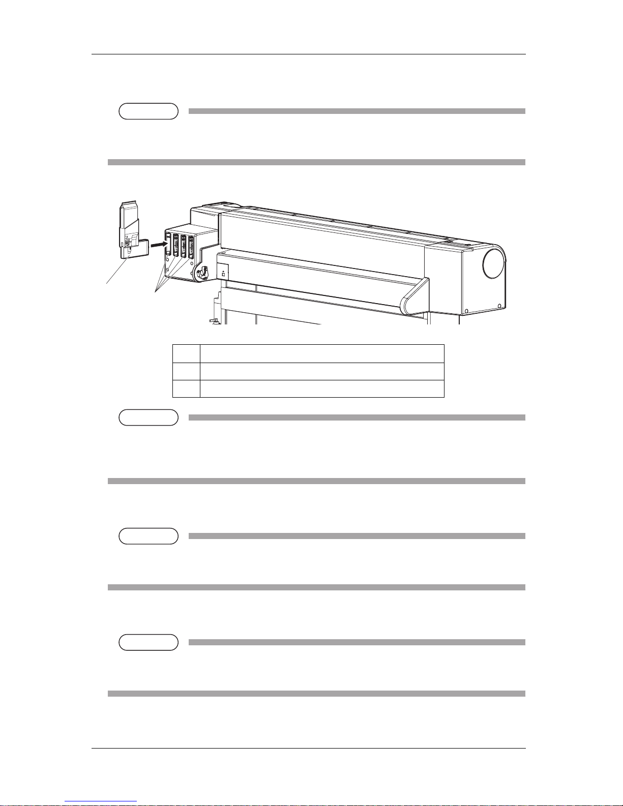
4 Daily maintenance VJ-1324 QUICK REFERENCE
4-6
2. Remove the high capacity pack adapter that you want to replace from the slot.
NOTE
NOTE
• Used ink packs should be put in a plastic bag, etc, and dispose of it in compliance with local
ordinance and instructions of local authorities.
NOTE
NOTE
• Do not remove only ink pack while high capacity pack adapter is installed on the printer. The
information of the remaining smart chip card will be rewritten and the ink pack will not be
usable.
3. Take out the new ink pack from the bag.
NOTE
NOTE
• Open the bag just before attaching the ink pack to the high capacity pack adapter.
Leaving the ink pack with the bag open for a long time may result in abnormal printing.
4. Install the ink pack and smart chip card to high capacity pack adapter.
NOTE
NOTE
• To install or remove the high capacity pack adapter to/from the ink pack and smart chip card,
refer to the operation manual included with high capacity pack adapter.
No. Name
1 High capacity pack adapter
2 Ink cartridge slots
1
2
Page 85

VJ-1324 QUICK REFERENCE 4 Daily maintenance
4-7
5. Shake the high capacity pack adapter gently two to three times and insert it to the slot.
NOTE
NOTE
• Make sure that the ink pack and smart chip are installed on the high capacity pack adapter
before inserting it to the slot. If the high capacity pack adapter is inserted into the slot without
the ink pack, the remaining information will be rewritten and the ink pack will not be usable.
• Insert the high capacity pack adapter all the way to the end of the slot.
6. Confirm that the operation panel returns to Normal.
NOTE
NOTE
• If the high capacity pack adapter is replaced during a print job, the printer resumes printing.
• Replacing the high capacity pack adapter is complete.
4.1.2 Replacing Cutter
This section describes when and how to replace the cutter.
(1) Replacement time
Replace the cutter when the following situation occurs.
a. When the paper is not cut smoothly
b. When the cut surface is feathered, etc
(2) Type
Our genuine cutter that is compatible with the printer is as follows.
(3) Replacing steps
Follow the procedure below to replace the cutter.
1. If the printer is turned ON, make sure the following.
• Printing or other operations are not in progress.
• The operation panel display is Normal.
Description Model No.
Cutter replacement blade VJ-CB
Page 86

4 Daily maintenance VJ-1324 QUICK REFERENCE
4-8
2. Display the CR Maintenance menu on the operation panel.
a. Press the [Menu] key on the operation panel.
• "Menu1: Setup>" is displayed on the operation panel.
• The operation panel shifts to the Setup menu display.
b. Press the [>] key on the operation panel.
• "Set 1: User Type" is displayed on the operation panel.
c. Press the [+] key or [–] key to select "Set20:CR Maintenance".
Page 87

VJ-1324 QUICK REFERENCE 4 Daily maintenance
4-9
d. Press the [Enter] key on the operation panel.
• "CR Mainte.: Start" is displayed on the operation panel.
• The display enters the CR Maintenance menu.
"5.1.19 CR Maintenance menu" in the Operation Manual
3. Press the [Enter] key on the operation panel.
• Maintenance starts.
• The print head moves to the left of the printer (cutter replacement position).
• "CR Maintenance: End" is displayed on the operation panel.
Page 88

4 Daily maintenance VJ-1324 QUICK REFERENCE
4-10
4. Open Maintenance cover.
NOTE
NOTE
• Replace the cutter in a short time.
Leaving the print head at the cutter replacement position may result in clogging of the print
head.
No. Name
1 Maintenance cover
Page 89

VJ-1324 QUICK REFERENCE 4 Daily maintenance
4-11
5. Press the tab of the cutter lightly, turn the cutter holder in the direction as illustrated below.
NOTE
NOTE
• Do not press the tab of the cutter strongly or suddenly let go of it.
There is a spring in the cutter holder and it may fly out.
• Do not push the cutter all the way in.
The cutter blade may damage the inside of the printer.
No. Name
1 Cutter holder
2 Cutter holder lever
2
1
Page 90

4 Daily maintenance VJ-1324 QUICK REFERENCE
4-12
6. Remove the cutter.
CAUTION
• Do not touch the blade edge.
It may cause an injury.
• Do not touch the cutter blade edge with a hard substance or drop the cutter.
The cutter blade may be damaged or chipped.
NOTE
NOTE
• Used cutter should be put in a plastic bag, etc, and dispose of it in compliance with local
ordinance and instructions of local authorities.
No. Name
1 Razor blade
1
Page 91

VJ-1324 QUICK REFERENCE 4 Daily maintenance
4-13
7. Install a new cutter as illustrated.
NOTE
NOTE
• Make sure that the spring in the cutter holder does not fly out while installing.
No. Name
1 Razor blade
1
Page 92

4 Daily maintenance VJ-1324 QUICK REFERENCE
4-14
8. Press the tab of the cutter lightly, return the cutter holder to its initial position.
NOTE
NOTE
• Do not press the tab of the cutter strongly or suddenly let go of it.
There is a spring in the cutter holder and it may fly out.
• Do not push the cutter all the way in.
The cutter blade may damage the inside of the printer.
• Refer to the illustrations below and install the cutter holder correctly.
If it is not installed correctly, it may cause an error.
If an error occurs, check if the cutter holder is installed correctly.
No. Name
1 Cutter holder
2 Cutter holder lever
2
1
Page 93

VJ-1324 QUICK REFERENCE 4 Daily maintenance
4-15
9. Close Maintenance cover.
10. Press the [Enter] key on the operation panel.
• The print head returns to its original position.
• "CR Mainte.: Start" is displayed on the operation panel.
No. Name
1 Maintenance cover
Page 94

4 Daily maintenance VJ-1324 QUICK REFERENCE
4-16
11. Press the [Menu] key on the operation panel.
• The printer enters Normal.
• Cutter replacement is complete.
Page 95

VJ-1324 QUICK REFERENCE 4 Daily maintenance
4-17
4.2 Cleaning the printer
Periodic (every month) cleaning is necessary to use the printer in good condition.
WARNING
• Do not insert or drop metal or flammable objects into the printer through openings
such as a vent.
It could lead to an electric shock or fire.
• If foreign substances or liquids such as water entered the printer, do not use the
printer as it is.
It could lead to an electric shock or fire.
Immediately turn OFF the power switch, disconnect the power plug from the electric
socket, and contact your local MUTOH dealer.
CAUTION
• When cleaning the areas other than the wiper, make sure to turn OFF the power and
unplug the power cable.
• Do not use volatile solvents such as thinner, benzene, or alcohol.
These solvents could cause damage to the paint.
• Be careful that no moisture enters the printer.
There is a possibility that the electric circuit inside the printer is short circuited.
• Do not open covers attached using screws under any circumstances.
This may cause an electric shock or a malfunction.
This section describes how to clean each part of the printer.
4.2.1 Cleaning the outer case
This section describes how to clean the outer case.
Wipe out dust and dirt attached to the outer case by using a soft cloth.
Page 96

4 Daily maintenance VJ-1324 QUICK REFERENCE
4-18
4.2.2 Cleaning the inside of the printer
This section describes how to clean the inside of the printer.
Follow the procedure below.
1. Open the front cover.
No. Name
1 Front cover
1
Page 97

VJ-1324 QUICK REFERENCE 4 Daily maintenance
4-19
2. Remove paper powder and dust attached to the pressurizing rollers using a soft brush.
NOTE
NOTE
• Do not blow paper powder inside the printer using tools such as an air duster.
It may cause an abnormal noise from the inside of the printer.
3. Apply a damp and tightly squeezed soft cloth to wipe out paper powder and ink attached to the platen
and media guide.
No. Name
1 Pressurizing rollers
No. Name
1 Platen
2 Media guide
1
1
2
Page 98

4 Daily maintenance VJ-1324 QUICK REFERENCE
4-20
4. Apply a damp and tightly squeezed soft cloth to wipe off the dirt of the unpainted (silver color) area
in the center of the grid roller.
4.2.3 Head cleaning
If printed data is blurred or lacks part of it, clean the print head surface and nozzle (Head cleaning).
Follow the procedure below to perform Head cleaning.
NOTE
NOTE
• When not using the printer for a long period (one week or more), perform Head cleaning once a
week.
If not performing Head cleaning, the print head is clogged. Doing so will preserve print quality.
• Remove media when cleaning.
Cleaning with media loaded may lead to contact between the print head and media.
1. Confirm that the operation panel is Normal.
2. Make sure that the media loading lever is lowered.
No. Name
1 Grid roller
1
Page 99

VJ-1324 QUICK REFERENCE 4 Daily maintenance
4-21
3. Press the [>] key on the operation panel to select the cleaning mode.
4. Press the [Cleaning] key on the operation panel for at least two seconds.
• "Cleaning **%" is displayed on the operation panel.
• Start Head cleaning.
• After Head cleaning is complete, the operation panel shifts to Normal.
NOTE
NOTE
• If blurs or lacking parts in printed media do not disappear with one time of Head cleaning,
perform Strong cleaning.
• If blurs or lacking parts in printed media do not disappear with several times of Head cleaning,
refer to "5 Troubleshooting", and take appropriate measures.
4.2.4 Cleaning the cleaning wiper
This section describes how to clean the cleaning wiper.
(1) Time for cleaning
Once a week, or when blurs or lacking parts appear on printed media after Head cleaning.
Page 100

4 Daily maintenance VJ-1324 QUICK REFERENCE
4-22
(2) Cleaning procedures
Follow the procedure below to clean the cleaning wiper.
NOTE
NOTE
• Use the cleaning stick to clean the cleaning wiper.
For cleaning stick, refer to "8.3 Options/Supply list" in the Operation Manual.
1. If the printer is turned ON, make sure the following.
• Printing or other operations are not in progress.
• The operation panel display is Normal.
2. Display the CR Maintenance menu on the operation panel.
a. Press the [Menu] key on the operation panel.
• "Menu1: Setup>" is displayed on the operation panel.
• The operation panel shifts to the Setup menu display.
b. Press the [>] key on the operation panel.
• "Set 1: User Type" is displayed on the operation panel.
 Loading...