

Page 1
Cutting Plotter
VC-600
MANUAL
MAINTENANCE
VC-1300
VC-1800
管理 No.
VCE-MM-02
Page 2

REVISION HISTORY
REV
Date
Sheet No
CONTENTS
00
Mar 26, 2013
All
Release
02
Aug 14, 2013
P9
Added VC-1800
MAINTENANCE MANUAL
01 Apr 30,2013 P.31
P.53-55
P.53-55
P.56
P.57
P31
P32
P33
P34
P36
P37
P38
P39
Changed Main board attachment position
Renamed parts
Added parts photo
Added Service parts(Pinch Roller, X/Y axis belt)
Correction of dimension(Specification list)
Added serial information
Added a notice of Firmware upgrade
Added chapter of “Enter Back up values”
Added chapter of “Initialize all settings”
Added chapter of “Restore the settings”
Changed the Title to “Factory default parameter”
Added a notice of Fuse position
Changed belt tension of VC-1800
VCE-MM-02
2
Page 3

MAINTENANCE MANUAL
Important Safety Information
Safety Instructions
General and Personal Safety Precautions
[PERSONAL SAFETY]
For personal safety, observe the following general precautions:
A second person should be available to disable the system in an emergency.
Wear appropriate protective gear that fits comfortably.
Do not wear loose-fitting clothes. If you are wearing a long-sleeved shirt, fold the cuffs up your
arm.
Never wear gloves close to moving parts.
Necklaces, ties and scarves should be tucked inside shirts.
Long hair should be covered.
[ELECTRICAL TOOL SAFETY]
When using Electrical Tools make sure to:
Use tools that are in good operating order. Any tool that appears electrically or mechanically
faulty must be labeled and sent immediately for repair.
Make sure that you are electrically insulated when using electrical tools. Wear rubber-soled
shoes and stand on a dry surface.
If, during the use of electrical equipment, you feel an electrical discharge (e.g. a tickling
sensation on your skin) immediately stop using that tool. Label it, and send it for repair.
[GENERAL SITE SAFETY REQUIREMENTS]
Fire extinguishers must be in working order and within easy reach.
The main power supply switch must be easily accessible.
The system site must be suitably illuminated from all sides.
Before operation, carefully read the warning labels on your Cutting plotter unit as well as the
cautions and warnings in this manual.
Connect the Cutting plotter to a properly grounded power outlet. Make sure the voltage level of
the Cutting plotter matches that of the power source.
Don't dissemble the unit while system power is on since the power supplies inside contain high
voltage.
Never leave the machine unattended during operation.
Follow the instructions on maintaining and cleaning your system. Not only will this enable you
to utilize your machine efficiently, but it will also ensure that your machine runs safely.
VCE-MM-02
3
Page 4

MAINTENANCE MANUAL
TABL E OF CONTENTS
REVISION HISTORY ...................................................................................... 2
Important Safety Information ........................................................................ 3
Safety Instructions ......................................................................................................................... 3
General and Personal Safety Precautions ........................................................................................... 3
TABLE OF CONTENTS .................................................................................. 4
Introduction and Component ....................................................................... 7
A. Main Unit Assembly ................................................................................................................... 8
B. Electronic and Electrical Assembly ............................................................................................ 9
C. Left End Assembl y .................................................................................................................. 10
D. Right End Assembly ................................................................................................................ 11
E. X Motor Bracket and Belt Assembly ........................................................................................ 12
F . Carriage Assembly................................................................................................................... 13
G. Pinch Roller Assembly ............................................................................................................ 14
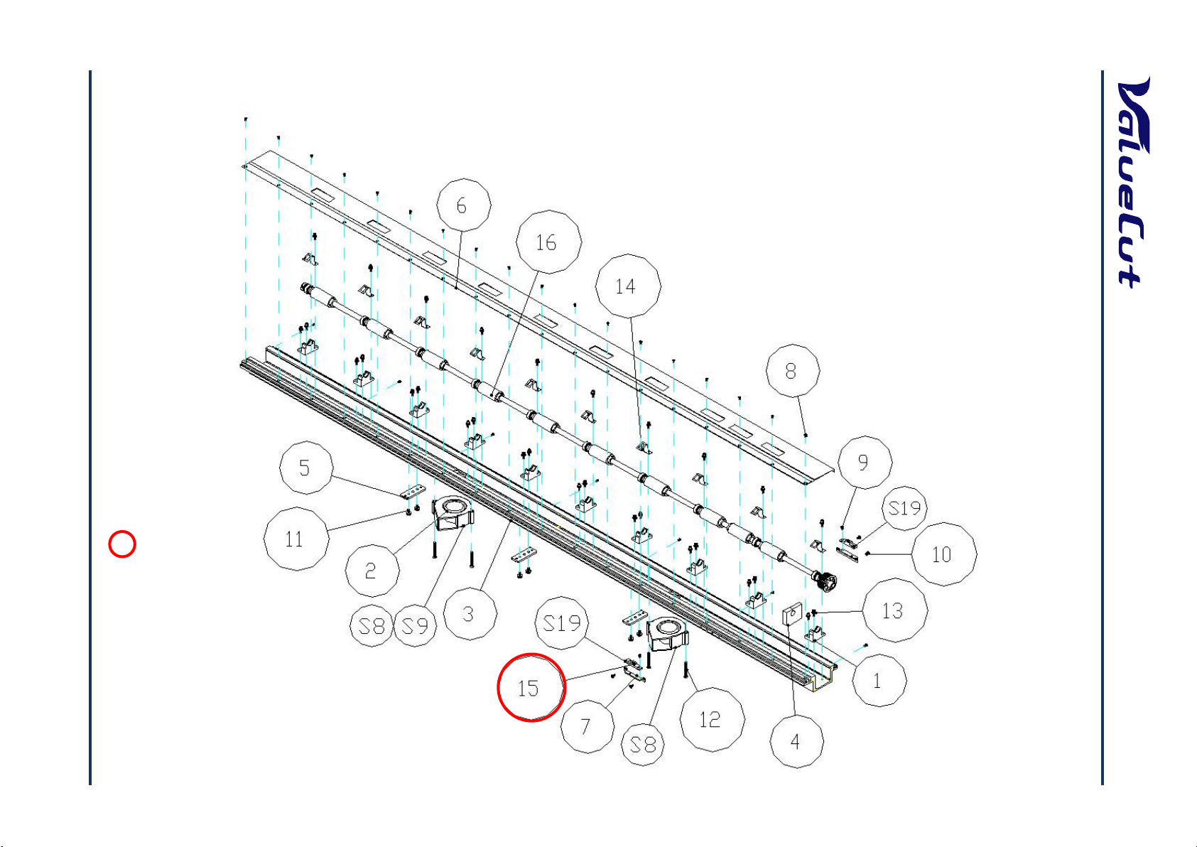
H. Main Beam Assembly ............................................................................................................. 15
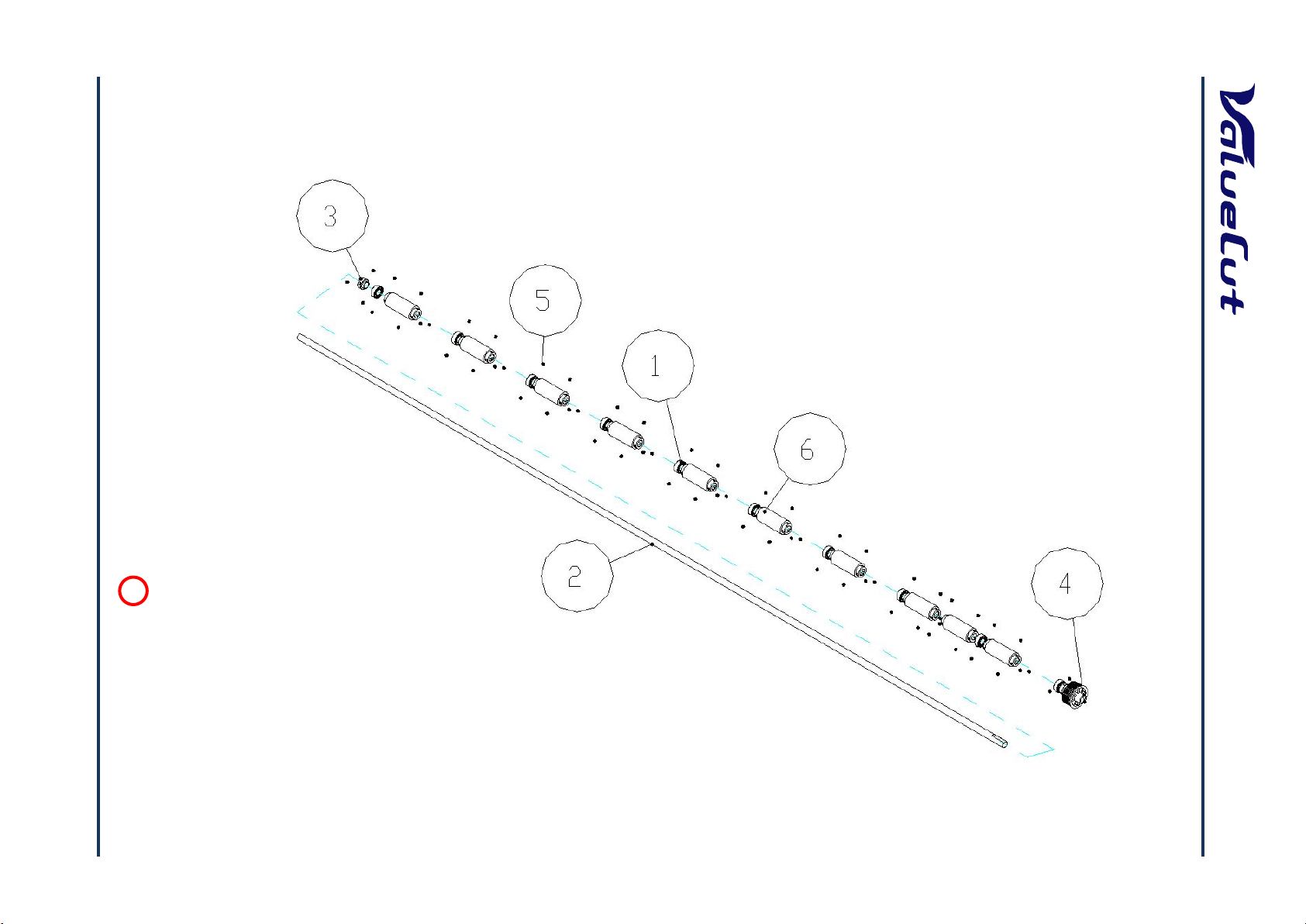
I. Drum Assembly ........................................................................................................................ 16
System Diagram and Components o f Ma in Board .................................... 17
System Diagram .......................................................................................................................... 18
Wiring Diagram............................................................................................................................ 19
Maintenance ................................................................................................ 20
Components Replacement and Belt Tension Adjustment ............................................................. 20
Removing the Front, Back, End and Top Covers ............................................................................... 20
Replacing the Pinch Roller Sets ......................................................................................................... 21
Replacing the Tool Carriage ............................................................................................................... 23
Replacing the Y -Motor ................................................................................................................. 27
Replacing the VCM PC Board ..................................................................................................... 29
Main board Connection or Replacement...................................................................................... 30
Firmware Upgrade ....................................................................................................................... 32
Enter Back up values................................................................................................................... 33
Initialize all settings ..................................................................................................................... 34
Restore the settings .................................................................................................................... 36
Factory default parameter ........................................................................................................... 37
Replacement of Fuses ................................................................................................................. 38
Adjusting the Tool Carriage Transmission Belt ............................................................................. 39
Adjusting the X Motor Tension Belt .............................................................................................. 40
Adjusting the Y Motor Tension Belt .............................................................................................. 41
Troubleshooting .......................................................................................... 43
VCE-MM-02
4
Page 5

MAINTENANCE MANUAL
Maintenance Diagnostics ............................................................................................................ 43
How to Begin Maintenance Diagnostics ...................................................................................... 43
Diagnostics Function Diagram ..................................................................................................... 44
Diagnostic Test f or SRAM and DRAM.......................................................................................... 45
Diagnostic Test for Lever Sensor ................................................................................................. 45
Diagnostic Test for Media Sensors .............................................................................................. 46
Diagnostic T est for Width Sensor ................................................................................................. 47
Diagnostic Test for Motor Encoder and Tool Holder Encoder ....................................................... 48
X Motor Encoder Test ......................................................................................................................... 48
Y Motor Encoder Test ......................................................................................................................... 48
Holder Encoder Test ........................................................................................................................... 49
Diagnostic Test for Motor Movement ........................................................................................... 50
Drum Movement?................................................................................................................................ 50
Carriage Movement? .......................................................................................................................... 51
Holder Movement? .............................................................................................................................. 51
Diagnostic Test for Interface ........................................................................................................ 52
Check RS-232 9600 ? ......................................................................................................................... 52
Check RS-232 19200 ? ....................................................................................................................... 52
Check Printer Port ............................................................................................................................... 52
Check USB port? ................................................................................................................................ 52
Problems and Solutions ............................................................................................................... 53
The line quality is not good enough at the corner or the end po int. ................................................... 53
The position of pinch roller cannot be detected so that the m edia width cannot be determined correct ly .
............................................................................................................................................................ 53
The function of "Set New O r igi n" does not work................................................................................. 53
Media shifts away when plotting a long drawing. ............................................................................... 53
The lines quality is wavy. .................................................................................................................... 54
Data loses when plotting. .................................................................................................................... 54
Fatal error occurs when loadi ng media. ............................................................................................. 54
Feel electrostatic discharge. ............................................................................................................... 54
Carriage locked, cannot move. ........................................................................................................... 55
The keyboard does not work. ............................................................................................................. 55
The machine makes noise when it is on the standby status. ............................................................. 55
The machine makes abnormal noise from the drum set whe n it is r unning. ...................................... 55
The tool carriage does not per f orm the up/down action. .................................................................... 55
There are some unexpect ed li nes on the final plot. ............................................................................ 56
There appears an unexpected tool force. ........................................................................................... 56
Media drops sometimes. ..................................................................................................................... 56
Appendix ...................................................................................................... 57
VCE-MM-02
5
Page 6

MAINTENANCE MANUAL
Recommend Service Parts List ................................................................................................... 57
Specification ................................................................................................................................ 61
Consumable Item List .................................................................................................................. 62
Optional Item List ........................................................................................................................ 62
VCE-MM-02
6
Page 7

MAINTENANCE MANUAL
Introduction and Component
This Maintenance Guide provides step-by-step instructions for replacing and maintaining the
components of the ValueCut Cutting plotter. It also includes a troubleshooting chapter with some
handy hints when problems arise or if the plotter does not operate properly. This Maintenance Guide
provides system diagrams, wiring diagrams and numerous flow charts detailing the maintenance
diagnostics built into the ValueCut Cutting plotter. Finally there is a parts list and spare parts order
form for convenience of ordering replacement parts.
For further Tech Support enquiries and assistance please contact the following Email address:
cs_service@mutoh.co.jp
The following diagrams represent all of the maintainable mechanical and electronic components of
the ValueCut Plotter with corresponding parts lists for convenient identification.
VCE-MM-02
7
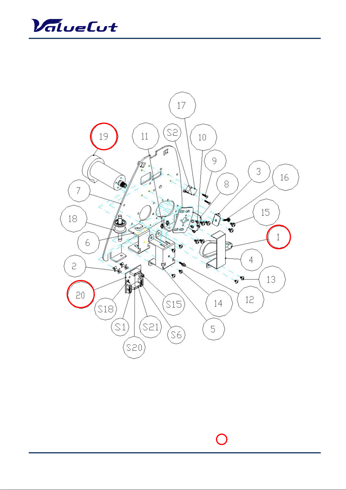
Page 8
VCE-MM-02
8
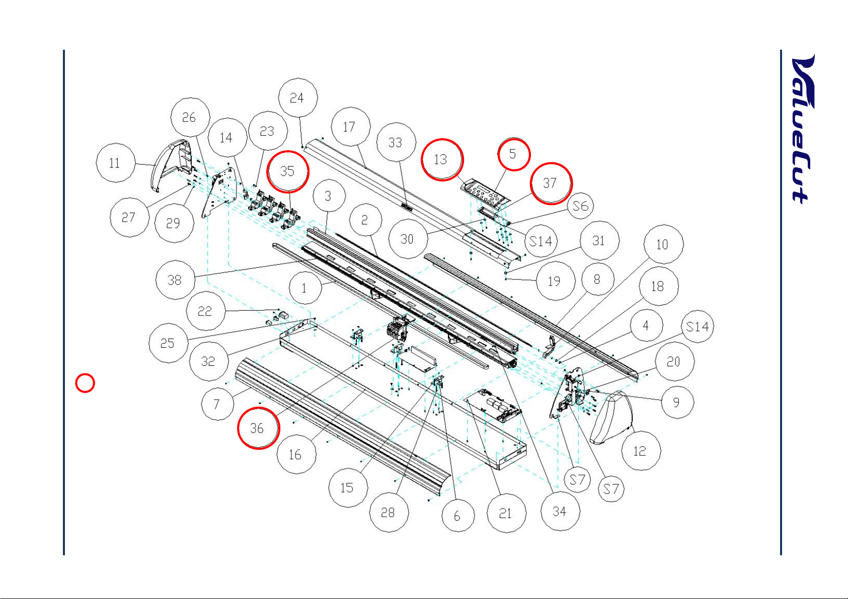
A. Main Unit Assembly
: Recommend Service Parts
MAINTENANCE MANUAL
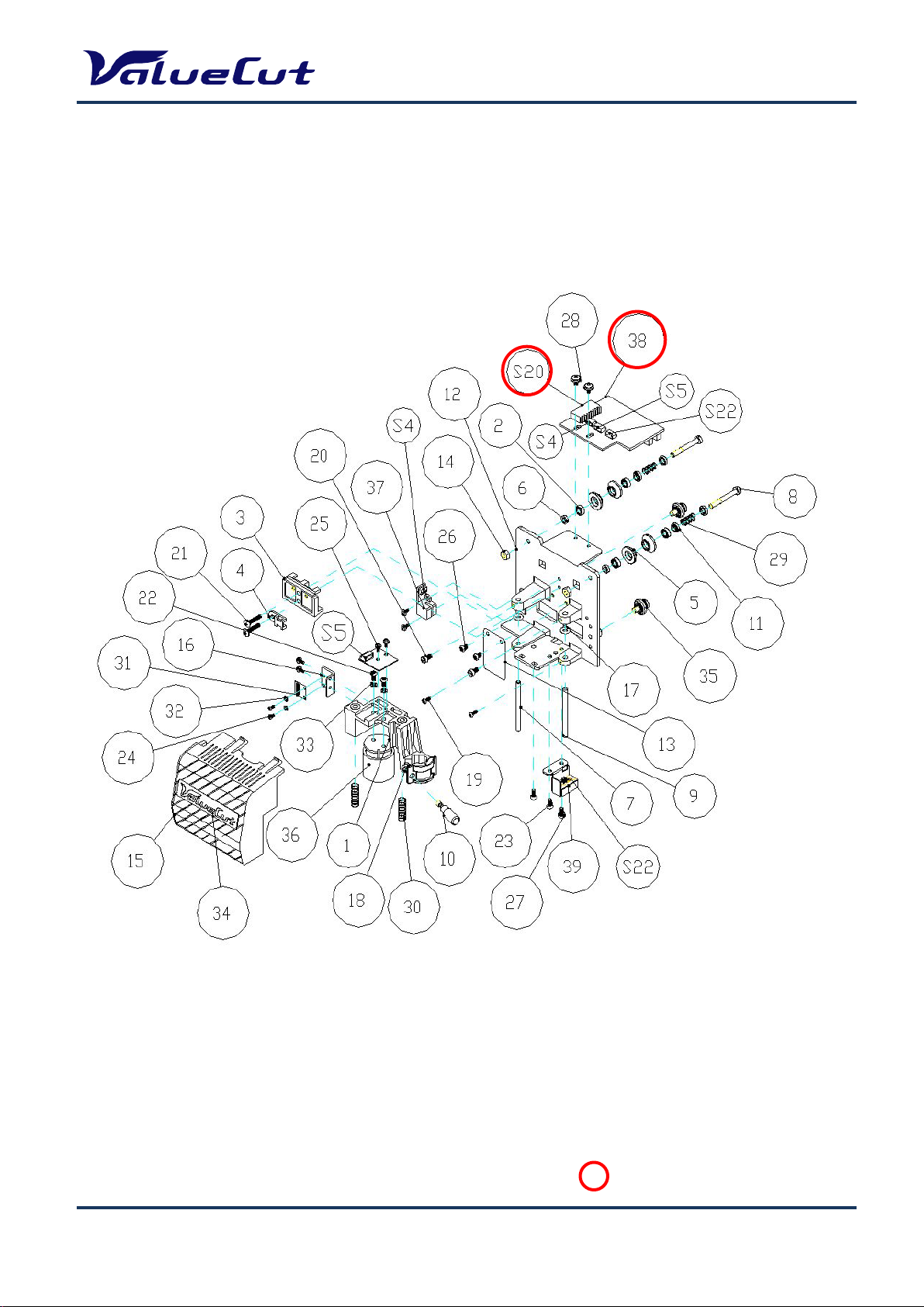
Page 9
VCE-MM-02
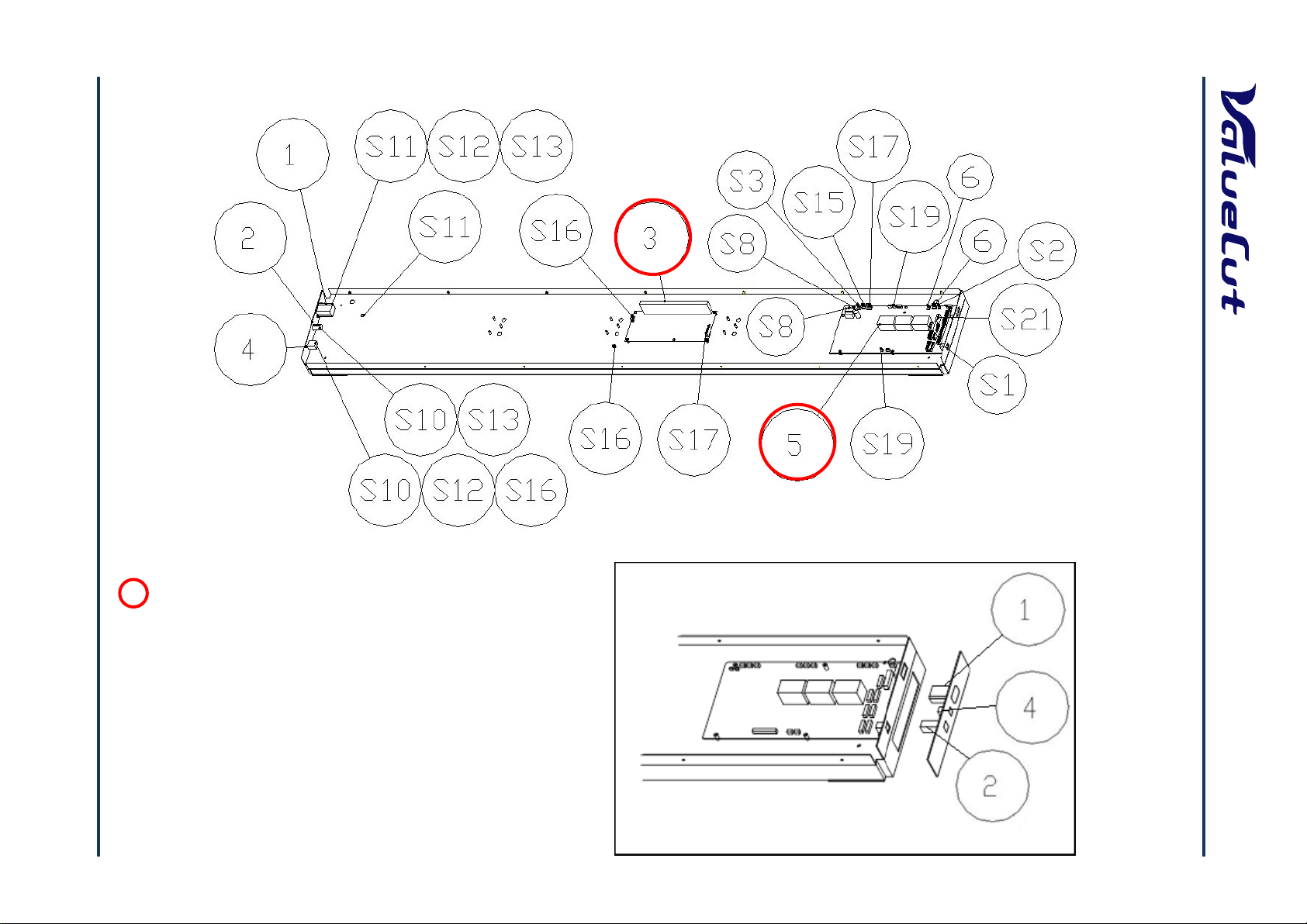
: Recommend Service Parts
VC-1800
VC-600/1300
9
B. Electronic and Electrical Assembly
MAINTENANCE MANUAL
Page 10
C. Left End A ssembly
: Recommend Service Parts
MAINTENANCE MANUAL
VCE-MM-02
10
Page 11
D. Right End A ssembly
MAINTENANCE MANUAL
VCE-MM-02
: Recommend Service Parts
11
Page 12
VCE-MM-02
: Recommend Service Parts
12
E. X Motor Bracket and Belt Assembly
MAINTENANCE MANUAL
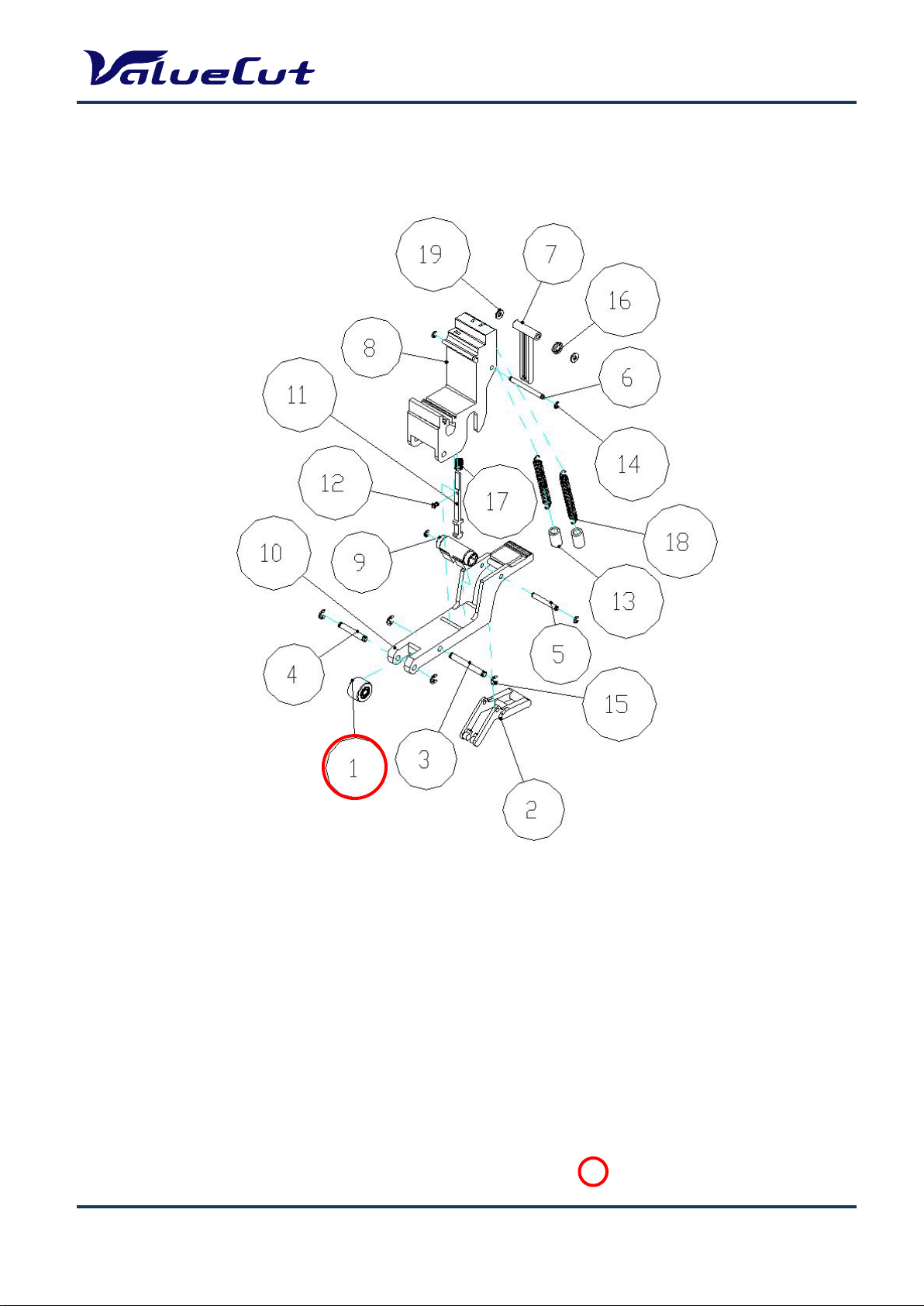
Page 13
F. Carriage A ssembly
: Recommend Service Parts
MAINTENANCE MANUAL
VCE-MM-02
13
Page 14
G. Pinch Roller A ssembly
: Recommend Service Parts
MAINTENANCE MANUAL
VCE-MM-02
14
Page 15
VCE-MM-02
: Recommend Service Parts
15
H. Main Beam Assembly
MAINTENANCE MANUAL
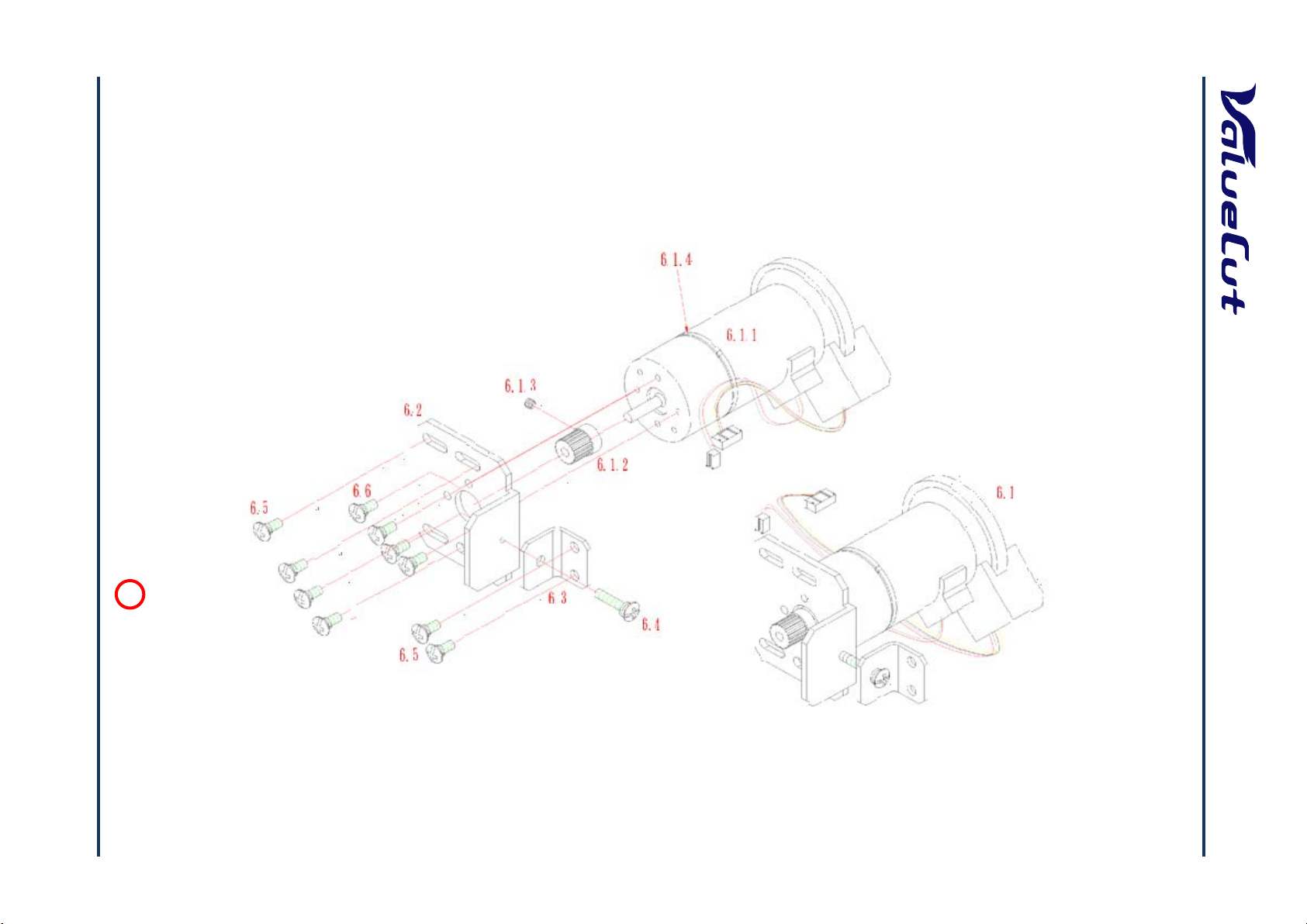
Page 16
VCE-MM-02
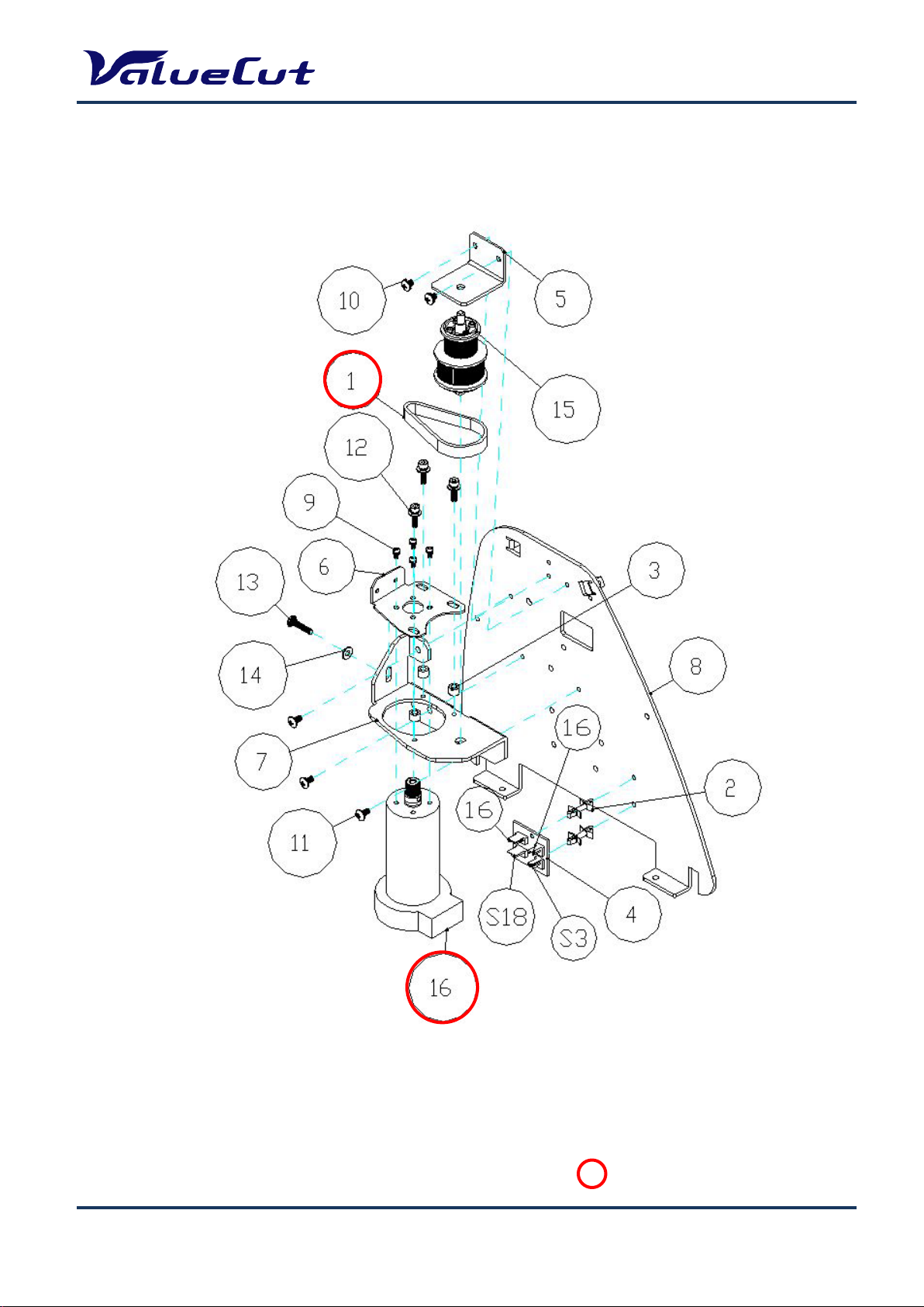
: Recommend Service Parts
16
I. Drum Assembly
MAINTENANCE MANUAL
Page 17

MAINTENANCE MANUAL
System Diagram and Components of Main Board
VCE-MM-02
17
Page 18
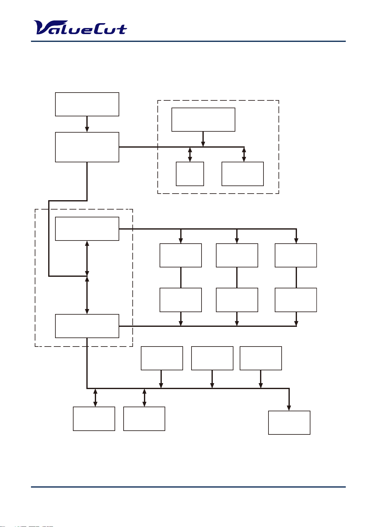
System Diagram
OSC 54MHz
OSC 54MHz
CPU
54MHz
MCF5206EAB54
FLASH
512KBx2 or 512KBx3
DRAM
1MB or 4MB
SRAM
64KB
TIMER & PWM
Generator
TIMER & PWM
Generator
X Motor
Driver
Y Motor
Driver
VCM
Driver
X Motor
Encoder
Y Motor
Encoder
VCM
Encoder
LCM
Display
USB
Port
Serial
Port
Media
Sensor (x2)
Carriage
Sensor
Lever
Sensor
Memory
FPGA
MAINTENANCE MANUAL
VCE-MM-02
18
Page 19
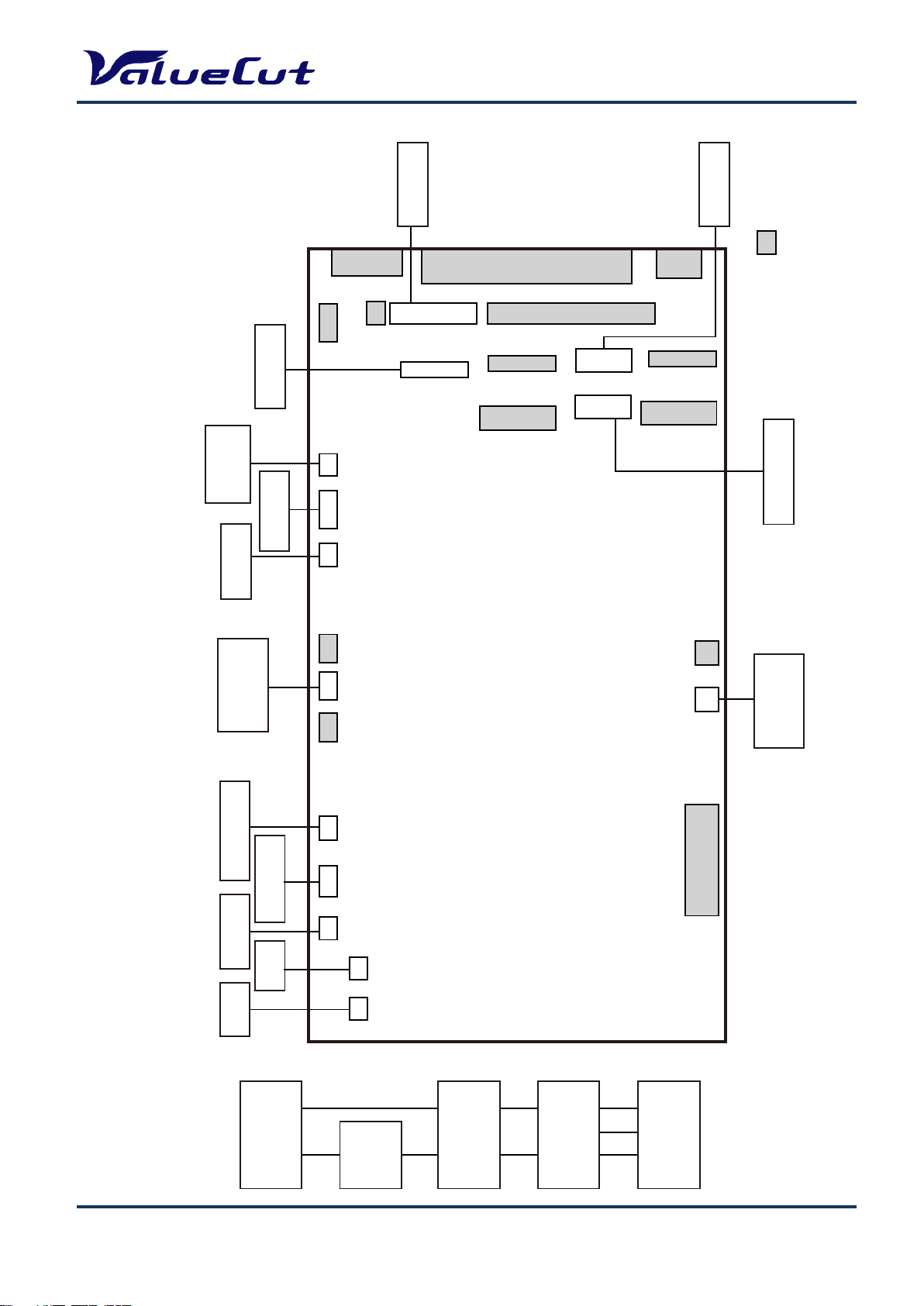
Wiring Diagram
FAN
FAN
Y Motor
Y Encoder
X Motor
X Encoder
JP10 JP11
JP15 JP18 JP25 JP6 JP5 JP22 JP21 JP23 JP7 JP16
Paper Rear
Sensor
Lever
Sensor
Serial Port
USB Port
JP1
JP3 JP4
JP30
JP27
JP33
JP8
JP31
JP28
JP20
JP10A
JP32
JP13
JP12
JP2
JP19
CR Board
Paper Front
Sensor
Control Panel
Power Board
FRONT SIDE
REAR SIDE
: N/C
MAIN BOARD
AC input
100v-240v
3A FUSE
On/Off
Switch
Power
Board
DC 40V/5V
Output
MAINTENANCE MANUAL
VCE-MM-02
19
Page 20

MAINTENANCE MANUAL
1. Remove the end cover screws.
2. Put equal pressure on both sides of the
End Cover and pull to remove.
1. Unscrew the 7 Front Cover and 7 Back Cover screws
Maintenance
This chapter deals with component replacement and maintenance of the ValueCut Cutting Plotter. It
gives detailed step-by-step instruction on how to replace or adjust the components of this machine.
Components Replacement and Belt Tension Adjustment
Removing the Front, Back, End and Top Covers
The following steps are those involved in removal of the front, back, end and top covers.
To Remove the End Covers:
To Remove the Front and Back Covers:
VCE-MM-02
20
Page 21

1. Unscrew the two screws at each end of the
2. Unplug the Control Panel Cable before
1. Pull down the Square Bar Lever to unlatch
To Remove the Top Cover:
MAINTENANCE MANUAL
Top Cover.
removing the top cover completely.
Replacing the Pinch Roller Sets
The following steps are those involved in replacing pinch roller sets.
To Unlatch the Pinch Roller Lever:
VCE-MM-02
the Pinch Rollers
21
Page 22

To Remove the Square Bar Holding Bracket:
1. Unscrew the 2 bracket screws.
2. Remove the bracket and washer.
1. Slide the pinch roller to the notch at the
2. Remove the pinch roller set through the
To Remove the Pinch Roller Sets:
MAINTENANCE MANUAL
right end of the Square Bar.
notch.
VCE-MM-02
22
Page 23

MAINTENANCE MANUAL
1. Unscrew the 2 retaining screws, but don’t remove them. Then turn the Adjustment
Adjustment Screw
Retaining Screws
Note: When re-installing the Pinch Roller Set, the Cam Roller must be aligned squarely to the
Square Bar.
Note: When aligning the Cam Roller please remember to keep the release grip locked down.
Note: Pinch-roller is color-coded by pressure force. When replacing the pinch-roller, make sure to
replace all the pinch-rollers with the same color.
Cam Roller
Release Grip
Replacing the Tool Carriage
The following are those you must follow to successfully replace the Tool Carriage.
To Loosen the Carriage Belt:
VCE-MM-02
Screw anti-clockwise to loosen the carriage belt.
23
Page 24

1. Depress the two locking clips at the top of the Tool Carriage Cover and pull the Cover
1. Pop up the plastic locking pins using a
2. Disconnect the Flat Sensor Cable.
To Remove the Tool Carriage cover:
MAINTENANCE MANUAL
To Prepare the Tool Carriage for Removal:
away.
flathead screwdriver.
VCE-MM-02
24
Page 25

MAINTENANCE MANUAL
3. Unbolt and remove nut A and B, and then unscrew both Bolt A
Belt B
Belt A
Separate the Sprung Washer/Rollers as seen in the figure
To Remove the Tool Carriage:
1.
and Bolt B until they are flush with the bracket.
VCE-MM-02
above.
25
Page 26

MAINTENANCE MANUAL
2. Swing the Tool Carriage down and out while keeping the
Sprung Washer/Rollers apart.
Note1: To install a new Tool Carriage or replace the original Tool Carriage simply reverse the steps
for Tool Carriage removal.
Note2: Remember to separate the Sprung Washer/Rollers, and then place them on the Carriage track
before you swing the Tool Carriage back into place
VCE-MM-02
26
Page 27

Replacing the Y-Motor
1. Loosen the all 3 tension-bracket retaining screws as well as the tension adjustment screw, but do
2. Depress the jumper clips, and pull to
3. Lift the belt off of the Y-motor,then unscrew
The following steps are those involved in the replacement of the Y-motor:
MAINTENANCE MANUAL
not remove them.
unplug the 2 Y-motor Jumpers.
VCE-MM-02
27
and remove the 4 Y-motor screws.
Page 28

MAINTENANCE MANUAL
Note1: To install or replace the Y-motor, simply reverse the steps to remove it.
Note2: After the Y-motor is in place, you must adjust the Y- motor belt tension as described in the
Y-motor belt tension adjustment section of this chapter.
Note3: Make the Y-motor jumper reconnection the last step after the Y-motor tension belt adjustment
when you have finished installing or replacing the Y-motor.
VCE-MM-02
28
Page 29

Replacing the VCM PC Board
The following is what is involved in replacement of the VCM PC board.
2. Unplug the two sensor connectors, and then unscrew the
two PC board screws to remove the board.
MAINTENANCE MANUAL
Note1: If the Pinch Roller Sensor is still not effective after replacement the Tool Carriage or the Flat
Cable may need replacement.
VCE-MM-02
29
Page 30

MAINTENANCE MANUAL
Fan
X motor encoder
X motor power
Level Switch Jumper
X motor power
1. Unplug all of the jumpers and connectors attached to all off board components.
Main board Connection or Replacement
Main board connection or replacement must follow the following steps to be sure that no damage
comes to either service personnel or the components:
Note1: To ensure absolute safety for service personnel and components, please follow the safety
instruction at the beginning of this manual, before installing or replacing any current
carrying components
T Parallel Port Connector o unplug the jumpers and connectors from the main board
Power Board jumper
Rear paper sensor
Com port extend jumper
Flat cable to carriage
X motor encoder
Note: Please refer to the Wiring Diagram for more detail on jumper and connector attachment
VCE-MM-02
Front paper sensor
30
Control Panel
USB Extend jumper
Page 31

MAINTENANCE MANUAL
1. Unscrew and remove the 5 restraining screws, and the pop out support to completely
remove the main board.
Note: To install or replace the main board simply reverse the steps to remove it.
Note: Main board attachment position changed as below (refer to the below image) from the “Serial
Interface connector (RS-232C) 9pin type machines.(Serial see below)
Remove the X motor before replacing the Main board.
VC-600 EVC2U0070~
VC-1300 EVC5U0068~
VC-1800 EVC7U0112~
VCE-MM-02
31
Page 32

MAINTENANCE MANUAL
1. Press indicated buttons by different port transmission
2. Select a desired firmware and port on "ValueCut File
3. When update of the firmware is completed, machines
Firmware Upgrade
When you change the Main board, it is necessary to upgrade firmware to latest version. This is done
as follows:
Note1: A main board is required to be pre-programmed with a loader in order to become flash able for
firmware uploading.
Note2: Normally, before a new spare main board is ready to ship, a loader or even a firmware
(smallest size of ordered model series) will be uploaded first on it. In case of functionality
problem happening due to incorrect firmware version, please verify if the existing firmware
on this main board is the desired one. A new program called (Firmware Upgrade) is a tool for
users to easily upgrade firmware, followed by the steps listed below.
Port to use USB port Serial port
Operation [Down] key + Power on [CUT TEST] key + Power on
listed on the table and open a "ValueCut File Uploade".
Uploader" dialogue box, then press START for uploading.
reboot with a normal mode automatically.
Note: After firmware installation, please perform initialize the setup information and re-enter the
setup information.
Note: Write down all the setting values before performing initialization. Re-enter the values again
from the panel after initialization is done. (“AAS Offset X/Y” and “Scale Length/Width” values
will be backed-up, so resetting will not be required.)
VCE-MM-02
32
Page 33

MAINTENANCE MANUAL
x2
Enter Back up values
Requires restore when updating the firmware and restore will initialize all the settings. Only "AAS
Offset X/Y", "Scale Length/Width" values can be backed-up even performing restore.
Press "TOOL SELECT" key and enter to tool setting menu.
Offline For
System Setup
1S 72 F 80 O0.250M
Press "
Press "CUT TEST" key and "ON/OFF LINE" key at the same time.
" key twice and display the restore menu.
}
Select:{} Ok:ENTER
Restore default ?
Select:{} Ok:ENTER
Press "ENTER" key.
VCE-MM-02
BackUp Setting
N:ONLINE Ok:ENTER
Sure to Backup
N:ONLINE Ok:ENTER
33
Page 34

Press "ENTER" key.
x2
MAINTENANCE MANUAL
Note: Only "AAS Offset X/Y", "Scale Length/Width" can be backed-up.
Note: If you want to Initialize the backup value, please go to Initialize all settings
Offline For
System Setup
Initialize all settings
Completely initialize all the settings including backed-up "AAS Offset X/Y", "Scale length/Width"
values.
Press "TOOL SELECT" key and enter to tool setting menu.
Press "
" key twice and display the restore menu.
}
Offline For
System Setup
1S 72 F 80 O0.250M
Select:{} Ok:ENTER
Restore default ?
Select:{} Ok:ENTER
VCE-MM-02
34
Page 35

Press "CUT TEST" key and "ON/OFF LINE" key at the same time.
MAINTENANCE MANUAL
Press "ENTER" key.
Press "DATA CLEAR" key.
BackUp Setting
N:ONLINE Ok:ENTER
Sure to Backup
N:ONLINE Ok:ENTER
Restore default ?
Select:{} Ok:ENTER
Press "ENTER" key then all the setting values will be initialized.
Turn off the power after initialization.
Re-Power On Please
VCE-MM-02
35
Page 36

Restore the settings
Return to the default value except backed-up values.
Press "TOOL SELECT" key and enter to tool setting menu.
MAINTENANCE MANUAL
Press "
Press "ENTER" key.
" key twice and display the restore menu.
}
Offline For
System Setup
1S 72 F 80 O0.250M
Select:{} Ok:ENTER
セッテイ ショキカ
Select:{} Ok:ENTER
Turn off the power after performing restore.
Re-Power On Please
VCE-MM-02
36
Page 37

MAINTENANCE MANUAL
Factory default parameter
Factory default parameter information is attached under the machine.
Below are the items for setup. Numbers shown in each parenthesis below are the example numbers
of this machine (serial# L75354).
AAS Offset (X= -0.6, Y= -0.5)
Scale Length (Length: 500 / 496.4 mm)
Width Length (Width: 500 / 500.2 mm)
AAS Offset setup steps
Press the [MICS] key by "OFF LINE" mode to enter the Setup Menu, then select [AAS Offset] and
input each X, Y value.
Scale setup steps
Press the [MICS] key by "OFF LINE" mode to enter the Setup Menu, then select [Scale Length] and
change the left number to [500]. Next change the right number to the value shown on the "Parameter
record card".
VCE-MM-02
37
Page 38

Replacement of Fuses
With your fingers apply equal pressure to both of the holding clips on the Fuse housing,
The Fuse pops out for easy replacement as follows:
MAINTENANCE MANUAL
Note: Position of the fuse (inlet switch) depends on the model.
1.
and push it out.
VC-600/1300:Leftside VC-1800:Right side
Handling clip
VCE-MM-02
38
Page 39

MAINTENANCE MANUAL
1. Move the tool carriage to the far left
5. To tighten the tension, turn the belt tension
screw clockwise. To loosen the tension turn
the belt tension screw anticlockwise, until
the desired adjustment tension is reached.
2. Loosen the 2 retaining screws on top of
3. Use a tension gauge to measure
the belt's tension by placing
the gauge's push arm to the
center of the belt, as seen in
4. To change belt tension adjust the belt
tension screw on the side of the
Adjusting the Tool Carriage Transmission Belt
When you replace the tool carriage or belt itself, the belt tension needs to be adjusted. This is done as
follows:
end of the guide beam after the tool
carriage or belt being replaced.
the figure above.
carriage belt roller housing.
the carriage belt roller housing.
The desirable tension is as follows.
VC-600 650g~850g
VC-1300 220g~320g
VC-1800 180g~200g
Note: Fasten the retaining screws on the top of the carriage belt roller housing once the adjustment
is made.
VCE-MM-02
39
Page 40

Adjusting the X Motor Tension Belt
2. Place the push-pull tension
the motor toward yourself
3. Tighten the 4 retaining screws
MAINTENANCE MANUAL
to lock the bracket in place.
4. Fix the tension retaining screw.
1. Loosen the 4 retaining screws
locking the X-motor bracket in
place.
gauge's hook-arm at the hole
of X motor bracket and pull
along the direction parallel to
the racket edge, and keep it at
the 4kg tension position.
Note: The belt connecting the drum and X motor needs to be tightened to a tension of 4 kg.
VCE-MM-02
40
Page 41

Adjusting the Y Motor Tension Belt
1. Loosen the 3 retaining screws
pull tension
the motor toward yourself
the line that passes through
3. Once the desired tension is
found tighten the 3 retaining
screws to lock the tension
MAINTENANCE MANUAL
locking the tension bracket in
place but do not remove them.
2. Place the push-
gauge's hook-arm at the hole
of Y motor bracket and pull
along the direction parallel to
the motor shaft and the drive
pulley shaft.
VCE-MM-02
bracket in place.
41
Page 42

MAINTENANCE MANUAL
3.
Tighten the tension screw to retain the tension.
Note: The belt connecting the drive pulley and Y motor needs to be tightened up with a tension of 4
kg.
VCE-MM-02
42
Page 43

MAINTENANCE MANUAL
Troubleshooting
Maintenance Diagnostics
This section provides maintenance diagnostics as troubleshooting aids. This diagnostic feature is to
check hardware to find out which components are good or defective. Using this diagnostic test facility
enables the diagnosing of the hardware components.
How to Begin Maintenance Diagnostics
To start the Maintenance Diagnostics facility hold down the On/Off Line button and CUT TEST
button while turning on the cutter. The following sub-sections will explain the function of each
maintenance diagnostic sequence.
VCE-MM-02
43
Page 44

Diagnostics Function Diagram
Holder Down ?
Carriage Movement ?
Check RS-232 ?
Check Printer Port ?
Check Width Sensor?
Check Media Sensors?
X Motor Encoder?
Y Motor Encoder?
Check USB Port ?
System cannot go on testing,
LCM display current message
Initial State
XMb DRAM OK
SRAM OK
<key
>key
<key
>key
<key
>key
<key
>key
Check Lever Sensor?
>key
Holder Encoder?
Down Movement ?
Exit Diagnostic Test
<key
MAINTENANCE MANUAL
more than 3 seconds.
<key >key
<key >key
Cancel key
>key
Please Reset Machine
<key >key
<key >key
VCE-MM-02
<key >key
<key >key
44
Page 45

MAINTENANCE MANUAL
or
Lever sensor
Diagnostic Test for SRAM and DRAM
This test provides the ability to diagnose the SRAM and DRAM. If these two components are bad,
replace them. Otherwise the cutting plotter will not work properly.
Diagnostic Test for Lever Sensor
This feature diagnoses the lever sensor. If the sensor is faulty, the cutting plotter cannot sense that
the pinch rollers have been lowered or not. If the lever sensor is down, you will see a lift the lever
message on the LCM. If the lever is up, you will see a lower the lever message on the LCM. You can
use the ON/OFF LINE KEY to abort your test when you have finished the lever sensor test.
Check Lever Sensor ?
Select:{} Ok:ENTER
Lever is Up now
ON/OFF
Lever is Down now
ON/OFF
[ENTER] Key [ON/OFF LINE] Key
VCE-MM-02
45
Page 46

MAINTENANCE MANUAL
or
Diagnostic Test for Media Sensors
This test is to diagnose the media sensors. If they are faulty, the cutting plotter cannot detect the
media length correctly. You can see the current front and rear sensor condition, you can turn it on or
off to see if sensors are out of order or not.
Check Media Sensor ?
Select:{} Ok:ENTER
[ENTER] Key [ON/OFF LINE] Key
Now Front is OPEN
Rear is OPEN ON/OFF
Now Front is CLOSE
Rear is CLOSE ON/OFF
VCE-MM-02
Paper sensor
46
Page 47

MAINTENANCE MANUAL
or
Diagnostic Test for Width Sensor
If the sensor is faulty, the cutter cannot sense the media width correctly. Refer to the maintenance
chapter to replace it. You must first move the tool carriage to the rightmost position; the lever must
be down to do this. Once this is done please move the tool carriage to left. Be careful when moving
the tool carriage close to the pinch roller, since the message changes quickly when sensor is between
on and off.
Check Width Sensor ?
Select:{} Ok:ENTER
Now Sensor is off
Move Carriage Slowly
Now Sensor is on
Move Carriage Slowly
[ENTER] Key [ON/OFF LINE] Key
VCE-MM-02
Width sensor
47
Page 48

MAINTENANCE MANUAL
[ON/OFF LINE] Key
Seconds later
[ENTER] Key
[ON/OFF LINE] Key
Seconds later
Diagnostic Test for Motor Encoder and Tool Holder Encoder
This feature provides the ability to diagnose the X and Y motor encoder and tool holder encoder. If
the encoder is defective, the cutting plotter cannot work properly. To check if the encoder is bad or
good, you can apply a slight force to the tested part (such as a drum, the tool carriage or the tool
holder) then examine the readings. If the encoder reading changes dramatically, the encoder is bad.
Refer to the maintenance chapter to replace the motor or tool carriage.
X Motor Encoder Test
X Motor Encoder ?
Select:{} Ok:ENTER
Y Motor Encoder Test
[ENTER] Key
Move Drum By Hand
Wait for 3 seconds
X Encoder Reading
1234 ON/OFF
Y Motor Encoder ?
Select:{} Ok:ENTER
Move Carriage By Han
d Wait for 3 seconds
VCE-MM-02
Y Encoder Reading
1234 ON/OFF
48
Page 49

Holder Encoder Test
[ENTER] Key
[ON/OFF LINE] Key
Seconds later
MAINTENANCE MANUAL
Holder Encoder ?
Select:{} Ok:ENTER
Move Holder Up/Down
Wait for 3 seconds
Holder Encoder Value
1234 ON/OFF
VCE-MM-02
49
Page 50

MAINTENANCE MANUAL
[ENTER] Key
[ON/OFF LINE] Key
[Forward] Key
Diagnostic Test for Motor Movement
This feature is to diagnose the X and Y motors and drivers. If you encounter a motor movement
problem, try to change the main board first. If the problem still remains after replacing the main
board, try replacing the motor.
Drum Movement?
Drum Movement ?
Select:{} Ok:ENTER
X Motor Moving Now
ON/OFF
X Motor Moving Now
Forward ON/OFF
[Backward] Key
X Motor Moving Now
Backward ON/OFF
VCE-MM-02
50
Page 51

Carriage Movement?
[ON/OFF LINE] Key
[Right] Key
[ENTER] Key
[ENTER] Key
[ON/OFF LINE] Key
[Left] Key
MAINTENANCE MANUAL
Carriage Movement ?
Select:{} Ok:ENTER
[ENTER] Key
Y Motor Moving Now
ON/OFF
Y Motor Moving Now
Right ON/OFF
Y Motor Moving Now
Left ON/OFF
Holder Movement?
[ON/OFF LINE] Key
Holder Down ?
Select:{} Ok:ENTER
Holder Moving Now
ON/OFF
Holder Moving Now
Down ON/OFF
Holder Moving Now
Up ON/OFF
VCE-MM-02
51
Page 52

Diagnostic Test for Interface
[ENTER] Key
[ENTER] Key
[ENTER] Key
[ENTER] Key
[ON/OFF LINE] Key
[ON/OFF LINE] Key
[ON/OFF LINE] Key
[ON/OFF LINE] Key
This is a function that is not normally used in maintenance work.
Check RS-232 9600 ?
Check RS-232 19200 ?
Check RS-232 9600?
Select:{} Ok:ENTER
Receive file from PC
1048576 Byte ON/OFF
MAINTENANCE MANUAL
Check Printer Port
Check USB port?
Check RS-232 19200?
Select:{} Ok:ENTER
Receive file from PC
1048576 Byte ON/OFF
Check Printer Port?
Select:{} Ok:ENTER
Receive file from PC
1048576 Byte ON/OFF
Check USB Port?
Select:{} Ok:ENTER
VCE-MM-02
Receive file from PC
1048576 Byte ON/OFF
52
Page 53

MAINTENANCE MANUAL
Problems and Solutions
This section discusses typical problems you may encounter while operating the cutting plotter and
offers you possible solutions.
The line quality is not good enough at the corner or the end point.
[Causation and recovery:]
Forgetting to fasten the tool (Fasten it.)
The blade is worn. (Change it.)
The offset value is wrong. (Correct the offset value.)
Media is not flat enough. (Reload the media.)
Media is wet. (Change it.)
The quality of media is not good enough. (Change the media.)
Drum or pinch roller is worn. (Change the drum set or pinch roller.)
The position of pinch roller cannot be detected so that the media width cannot be determined correctly.
[Causation and recovery:]
Forgetting to lower the pinch roller. (Enable the pinch roller and push the lever forward to lower
down the pinch roller)
The orientation of the width sensor on the carriage PCB is not correct. (Adjust the orientation of
the carriage PCB)
The position of the width sensor on the carriage PCB is too high to sense the block bar on the
pinch roller. (Lower the carriage PCB)
Flat cable is broken. (Change it.)
Width sensor is damaged. (Change it.)
Carriage PCB set is damaged. (Change carriage set.)
The function of "Set New Origin" does not work.
[Causation and recovery:]
The origin point will be set by pressing the ENTER button when the ValueCut is in an OFFLINE
state, only then will the LCD display the distance between the new and old origin.
Media shifts away when plotting a long drawing.
[Causation and recovery:]
The media is not accurately aligned. (Reload the media.)
VCE-MM-02
53
Page 54

MAINTENANCE MANUAL
Pre-run the media back and forth using the arrow key will help. (Reload the media and pre-run.)
The edge of the media is not straight. (Change the media.)
Media is too thin. (Change it.)
Drum is coated with paper chips or dust. (Clean the surface of drum.)
Drum or pinch roller is worn. (Change the drum set or pinch roller.)
The lines quality is wavy.
[Causation and recovery:]
Forget to fasten the tool fastening screw. (Fasten it.)
The blade is worn. (Change it.)
The acceleration is too high. (Set the acceleration to a lower value; please refer to the default
value.)
The carriage belt tension is incorrect. (Adjust the belt tension.)
X or Y motor belt tension is incorrect. (Adjust the belt tension.)
The spring loading bearing of carriage is damaged. (Change the carriage set.)
The length of the media is too short in X direction. (Change the media.)
Media is too thin. (Change it.)
Drum or pinch roller is worn. (Change the drum set or pinch roller.)
X or Y motor is damaged. (Change it.)
Data loses when plotting.
[Causation and recovery:]
Memory chip is bad. (Change it.) Main board set is bad. (Change it.)
Fatal error occurs when loading media.
[Causation and recovery:]
Forget to pull out some media from the media roll. (Pull out some media from the roll before you
start to load media.)
X motor belt is too tight. (Adjust the belt tension.)
Feel electrostatic discharge.
[Causation and recovery:]
Power out let does not have ground connection. (Improve it.)
VCE-MM-02
54
Page 55

MAINTENANCE MANUAL
Carriage locked, cannot move.
[Causation and recovery:]
The spring loading bearing of carriage is damaged. (Change the carriage set.)
The carriage belt is too tight. (Adjust the belt tension.)
Some fasten screws are loose so that the shaft bearing of carriage belt drops. (Fasten the
screws.)
The keyboard does not work.
[Causation and recovery:]
The connection between keyboard and main board is broken. (Re-plug the connector or change
the keyboard set.)
Dust or moist surface makes a bad keyboard contact. (Change the keyboard set.)
The machine makes noise when it is on the standby status.
[Causation and recovery:]
The screws of tool carriage cover are loose. (Fasten the screws.)
X or Y motor belt is loose. (Adjust the belt tension.)
The carriage belt is loose (Adjust the carriage belt tension)
The driver board set is damaged. (Change it.)
The machine makes abnormal noise from the drum set when it is running.
[Causation and recovery:]
X or Y motor belt is loose. (Adjust the belt tension.)
The driver board set is damaged. (Change it.)
The gear at the left of drum set is not tightly mounted on the shaft. (Change it.)
The screws that fasten the drum to the shaft are loose. (Fasten the screws.)
X or Y motor is damaged. (Change it.)
The tool carriage does not perform the up/down action.
[Causation and recovery:]
The blade holder is not installed properly. (Re-install it, please refer to user’s guide.)
The flat cable is broken. (Change it.)
The carriage PCB is damaged. (Change it.)
VCM is damaged. (Change the Carriage set.)
The encoder of the VCM is damaged. (Change the Carriage set.)
VCE-MM-02
55
Page 56

MAINTENANCE MANUAL
The driver board set is damaged. (Change it.)
The linear bearing shaft of VCM is rusty. (Change the Carriage set.)
The two small bearings clamp the linear bearing shaft too tight. (Adjust them).
There are some unexpected lines on the final plot.
[Causation and recovery:]
The blade holder is not installed properly. (Re-install it; please refer to user’s guide.)
The media is not flat enough. Maybe there are some bubbles on the surface. (Re-load the media)
The fan cannot make enough airflow to suck the media. (Change the fan or driver board)
The carriage does not perform the up action. (Please refer to the previous paragraph)
The command of output file of cutting software package is not compatible with HPGL or HPGL/2.
(Ask your cutting software package agent for help.)
There are some communication errors. (Check the communication protocol.)
There appears an unexpected tool force.
[Causation and recovery:]
The setting of tool force is wrong. (Reset the tool force.)
The blade length out of the blade holder is too short. (Re-load the blade.)
The initial force setting is wrong. (Reset the initial force. please contacts the manufacturer.)
VCM is damaged. (Change the carriage set.)
VCM encoder is damaged. (Change the carriage set.)
Media drops sometimes.
[Causation and to recovery:]
Media is loaded askew. (Re-load the media.)
The position of pinch roller is not on the top of drum. (Move the pinch roller to a right position.)
The edge of media is broken. (Change the media.)
The front of media is not even. (Cut the front edge of the media evenly and reload the media.)
Drum is coated with paper chips or dust. (Clean the surface of drum.) Drum or pinch roller is
worn. (Change the drum set or pinch roller.)
VCE-MM-02
56
Page 57

Appendix
Recommend Service Parts List
Part no. Part name VC-600 VC-1300 VC-1800 Location
Control panel assembly(MUT)
MAINTENANCE MANUAL
ME-G290072900G-00
ME-G29005258G-00
ME-G234000330G-00
V V V A-13
Control Panel Board assembly
V V V A-37
Control Panel Sticker.(MUT)
V V V A-5
Watch dog-Interface converter board
Assembly
ME-G29005256G-00
Motor Assembly
ME-G29001804G-00
VCE-MM-02
V V V D-20
V V V C-16, D-19
57
Page 58

MAINTENANCE MANUAL
Part no. Part name VC-600 VC-1300 VC-1800 Location
Flat cable Assembly VC6 (L=120cm)
ME-G290071460G-00
ME-G290071420G-00
ME-G290071450G-00
Flat cable assembly VC13 (L=195cm)
Flat cable assembly VC18 (L=250cm)
Pinch roller Assembly
V
V
V
F-S20
F-S20
F-S20
ME-G29002348G-00
ME-G29004369G-00
ME-G29004854G-00
AASII carriage board assembly
Paper Sensor Assembly VC6/VC13
V V V A-35
V V V F-38
V V
H-15
VCE-MM-02
58
Page 59

MAINTENANCE MANUAL
Part no. Part name VC-600 VC-1300 VC-1800 Location
Paper Sensor Assembly VC18
ME-G29004856G-00
ME-G29004680G-00
ME-G29005316G-00
Carriage assembly VC6/VC13
Carriage assembly VC18
2 in 1 Cutter main board
V V
V
V
H-15
A-36
A-36
ME-G29005378G-00
250W Isolated Dual Output with PFC
Function(PID-250C)
ME-G24500083G-00
V V V B-5
V V V B-3
VCE-MM-02
59
Page 60

MAINTENANCE MANUAL
Part no. Part name VC-600 VC-1300 VC-1800 Location
Pinch Roller
ME-G20200003G-00
ME-G20600009G-00
ME-G20600007G-00
V V V G-01
X - axis Belt (2GT-L210-W10)
V V V D-01
Y – axis Belt (2GT-L172-W10)
V V V C-01
VCE-MM-02
60
Page 61

Specification
Model Number
VC-600
VC-1300
VC-1800
Operation Method
Paper Moving Type
Max. Cutting Width
610mm(24in)
1320mm(52in)
1830mm(72in)
Max. Media Loading Width
770mm(30.3in)
1594mm(62.7in)
1900mm(74.8in)
Min. Media Loading Width
50mm(1.97in)
300mm(11.8in)
Number of Pinch Rollers
3 4 6
Drive Motor
DC Servo Control
Cutting Force
5~600 g
Max. Cutting Speed
1530 mm/sec (60ips / Diagonal)
Blade Offset
0~1.0 mm (0.025mm/step)
Memory Buffer
4 MB
Interface
USB 2.0 (Full Speed) and Serial (RS-232C)
Software Resolution
0.025 mm
Distance Accuracy
±0.254 mm or ±0.1% of move, whichever is greater
Curve & Arc Smoothing
Yes
Configurable Origin
Yes
Test Cut capability
Yes
Repeat
Yes
Copy
Yes
Pouncing
Yes
Control Panel
LCD (20 digits x 2lines), 14keys, 1 Power LED
Power Supply
AC 100-240V, 50~60 Hz (Auto switching)
Power Consumption
110 watts - 251.8 watts
Net Weight
18 kg
50 kg
64 kg
Stand
Optional
Standard
Media Basket
Optional
Standard
Environment
Humidity
25% - 75%
Max. Cutting Length 50m(164ft)
Acceptable Material Thickness 0.8mm(0.03in)
Acceleration 4.2 G (Gravity)
MAINTENANCE MANUAL
Type of Command HP-GL, HP-GL/2
Mechanical Resolution
Repeatability ±0.1mm
Tangential Yes
Automatic-Aligning System Completely Automatic Contour Cutting System for print to cut solution
Dimension (HxWxD) mm 412 * 950 * 486 1113 * 1774 * 651 1127 * 2170 * 756
0.006mm
Operation
The specification and data sheet may vary with different materials used. In order to obtain the
best output quality, please maintain the machine regularly and properly.
MUTOH reserves the right to change the specifications at any time without notice.
The above listed specification values are effective only when operated with media certified by
MUOTH.
VCE-MM-02
Temperature 15 ゚ C – 30 ゚ C, 60 ゚ F – 86 ゚ F
61
Page 62

Consumable Item List
VC-CHD
Cutting Blade Holder
Cutting Blade Green Cap (60゚0.5) (1pcs/box)
VC-CBBU1
Cutting Blade Blue Cap (60゚0.25) (1pcs/box)
VC-CMAT
Cutting Pad (6mmx10m)
VC-SB
Safe Blade
Item Number Item Name
MAINTENANCE MANUAL
VC-CBRE5
VC-CBGR1
VC-CBBK1
VC-CBYE5
PSGB-BK Pressurized Ballpoint Pen
VC-PT Pouncing Tool assembly (Diameter:1.5mm)
VC-PMAT Pouncing Pad (1.5m/Roll)
VC-TW Tweezers (L=11cm, W=0.85cm)
Optional Item List
Cutting Blade Red Cap (45 ゚ 0.25) (5pcs/box)
Cutting Blade Black Cap (42 ゚ 0.175) (1pcs/box)
Cutting Blade Yellow Cap (25 ゚ 0.25) (5pcs/box)
Item Number Item Name
VC-STD600 Stand for VC-600
VC-TBL Add-on flat table for VC-600
VC-RS RS-232 Cable (25pin)
VC-USB USB Cable
VCE-MM-02
62
Page 63

MUTOH INDUSTRIESLTD.
http://www.mutoh.co.jp/en/
MUTOH AMERICA INC.
http://www.mutoh.com
MUTOH BELGIUM nv
http://www.mutoh.be
MUTOH DEUTSHLAND GmbH
http://www.mutoh.de/
MUTOH North Europ e S.A.
http://www.segroup.lu/
MUTOH HONGK O NG LT D.
MUTOH SINGAPORE PTE. LTD.
MUTOH AUSTRALIA PTY . LTD.
http://mutoh-au.com/
Tel:81-(0)3-6758-7030
Fax:81-(0)3-6758-7021
E-mail:cs_service@mutoh.co.jp
Tel:352-445-906
Fax:352-447-093
E-mail:info@segroup.lu
Tel:+1-480-968-7772
Fax:+1-480-968-7990
E-mail:sales@mutoh.com
Tel:852-2377-3411
Fax:852-2377-3422
http://www.mutoh.co.jp/en/
Tel:32-(0)59-561400
Fax:32-(0)59-807117
E-mail:mutoh@mutoh.be
Tel:65-6325-3150
Fax:65-6220-4342
http://www.mutoh.co.jp/en/
Tel:49-(0)211-385474-0
Fax:49-(0)211-385474-74
E-mail:vertrieb@mutoh-gmbh.de
Tel:61-2-9437-1366
Fax-61-2-9436-2871
E-mail:sales@mutoh-au.com
 Loading...