

Page 1
No.
VC2E-MM-00
Cutting Plotter
VC2-600
VC2-1300
VC2-1800
MAINTENANCE
MANUAL
Page 2

REVISION HISTORY
REV
Date
Sheet No.
CONTENTS
00
Apr 3, 2019
All
New
MAINTENANCE MANUAL
VC2E-MM-00
2
Page 3

MAINTENANCE MANUAL
Important Safety Information
Safety Instructions
General and Personal Safety Precautions
[PERSONAL SAFETY]
For personal safety, observe the following general precautions:
A second person should be available to disable the system in an emergency.
Wear appropriate protective gear that fits comfortably.
Do not wear loose-fitting clothes. If you are wearing a long-sleeved shirt, fold the cuffs up your arm.
Keep your hands away from moving parts.
Necklaces, ties and scarves should be tucked inside shirts.
Long hair should be covered.
[ELECTRICAL TOOL SAFETY]
When using Electrical Tools make sure to:
Use tools that are in good operating order. Any tool that appears electrically or mechanically faulty
must be labeled and sent immediately for repair.
Make sure that you are electrically insulated when using electrical tools. Wear rubber-soled shoes
and stand on a dry surface.
If, during the use of electrical equipment, you feel an electrical discharge (e.g. a tickling sensation on
your skin) immediately stop using that tool. Label it, and send it for repair.
[GENERAL SITE SAFETY REQUIREMENTS]
Fire extinguishers must be in working order and within easy reach.
The main power supply switch must be easily accessible.
The system site must be suitably illuminated from all sides.
Before operation, carefully read the warning labels on your Cutting plotter unit as well as the cautions
and warnings in this manual.
Connect the Cutting plotter to a properly grounded power outlet. Make sure the voltage level of the
Cutting plotter matches that of the power source.
Don't dissemble the unit while system power is on since the power supplies inside contain high
voltage.
Never leave the machine unattended during operation.
Follow the instructions on maintaining and cleaning your system. Not only will this enable you to
utilize your machine efficiently, but it will also ensure that your machine runs safely.
VC2E-MM-00
3
Page 4

MAINTENANCE MANUAL
TABLE OF CONTENTS
REVISION HISTORY .............................................................................................. 2
Important Safety Information .............................................................................. 3
Safety Instructions ........................................................................................................ 3
General and Personal Safety Precautions ................................................................. 3
TABLE OF CONTENTS ......................................................................................... 4
Introduction ........................................................................................................... 7
Exploded View ...................................................................................................... 8
A. Main Unit Assembly .................................................................................................. 8
B. Electronic and Electrical Assembly ........................................................................... 9
C. Left End Assembly .................................................................................................. 10
D. Right End Assembly ............................................................................................... 11
E. X Motor Bracket and Belt Assembly ....................................................................... 12
F. Carriage Assembly .................................................................................................. 13
G. Pinch Roller Assembly ........................................................................................... 14
H. Main Beam Assembly ............................................................................................. 15
I. Drum Assembly ........................................................................................................ 16
J. Stand and Basket .................................................................................................... 17
System Diagram and Wiring Diagram .............................................................. 18
System Diagram ......................................................................................................... 19
Wiring Diagram - Main Board ................................................................ ...................... 20
Wiring Diagram - Driver Board .................................................................................... 21
Maintenance ........................................................................................................ 22
Parts Replacement ..................................................................................................... 22
Removing Covers .................................................................................................... 22
Replacing Pinch Roller Sets .................................................................................... 24
Replacing Carriage Board ........................................................................................ 26
Replacing Tool Carriage ........................................................................................... 28
Replacing Y-Motor .................................................................................................... 30
Replacing X-Motor ................................................................................................... 31
Replacing Main Board .............................................................................................. 32
Replacing Driver Board ............................................................................................ 33
Replacing Power Supply board ................................................................ ................ 34
Replacing Fuses ...................................................................................................... 35
Firmware Update ........................................................................................................ 36
Backup of Settings ...................................................................................................... 37
Initialization of Settings ............................................................................................... 38
VC2E-MM-00
4
Page 5

MAINTENANCE MANUAL
Restoration of Settings ................................................................................................ 40
Factory Default Parameter .......................................................................................... 41
Belt Tension Adjustment .............................................................................................. 42
Tool Carriage Belt .................................................................................................... 42
X Motor Belt ............................................................................................................. 43
Y Motor Belt ............................................................................................................. 44
Troubleshooting .................................................................................................. 45
Maintenance Diagnostics ............................................................................................ 45
How to Start Maintenance Diagnostics .................................................................... 45
Diagnostic Test for SRAM and DRAM ...................................................................... 47
Diagnostic Test for Lever Sensor ............................................................................. 47
Diagnostic Test for Media Sensors........................................................................... 48
Diagnostic Test for Width Sensor ............................................................................. 49
Diagnostic Test for Motor Encoder and Tool Holder Encoder .................................. 50
X Motor Encoder Test ........................................................................................... 50
Y Motor Encoder Test............................................................................................ 50
Holder Encoder Test ............................................................................................. 51
Diagnostic Test for Motor Movement........................................................................ 52
Drum Movement ................................................................................................... 52
Carriage Movement .............................................................................................. 53
Holder Movement .................................................................................................. 53
Diagnostic Test for Interface .................................................................................... 54
Check RS-232 9600 .............................................................................................. 54
Check RS-232 19200 ............................................................................................ 54
Check Printer Port ................................................................................................. 54
Check USB port .................................................................................................... 54
Problems and Solutions .............................................................................................. 55
The cutting quality is not good at the corner or the end point. ................................. 55
The media width cannot be detected since the pinch roller position is not clear. ..... 55
The function of "Set New Origin" does not work. ..................................................... 55
Media shifts away when plotting a long drawing. ..................................................... 56
The cutting line is wavy. ........................................................................................... 56
Data are missing when plotting. ............................................................................... 56
Serious error occurs when feeding media. .............................................................. 56
Static electricity is generated. .................................................................................. 57
The carriage is locked and cannot move. ................................................................ 57
The keyboard does not work. ................................................................................... 57
Abnormal noise occurs during standby mode. ......................................................... 57
Abnormal noise occurs from the drum during operation. ......................................... 57
VC2E-MM-00
5
Page 6

MAINTENANCE MANUAL
The tool carriage does not move up/down. .............................................................. 58
Some unexpected lines are plotted. ......................................................................... 58
The cutting force is not applied correctly. ................................................................. 58
Media drops sometimes. .......................................................................................... 59
Error Message and Handling ...................................................................................... 60
Serious Error ............................................................................................................ 60
Operation Error ........................................................................................................ 61
Appendix ............................................................................................................. 62
Recommend Service Parts List ................................................................................... 62
Specification ................................................................................................................ 66
Consumable Item List ................................................................................................. 67
Optional Item List ........................................................................................................ 67
VC2E-MM-00
6
Page 7

MAINTENANCE MANUAL
Introduction
This Maintenance Guide provides step-by-step instructions for replacing and maintaining the components
of the ValueCut Cutting plotter. It also includes a troubleshooting chapter with some handy hints when
problems arise or if the plotter does not operate properly. This Maintenance Guide provides system
diagrams, wiring diagrams and numerous flow charts detailing the maintenance diagnostics built into the
ValueCut Cutting plotter. Please refer to the parts list and exploded views for convenience of ordering
replacement parts.
For further Tech Support enquiries and assistance please contact the following Email address:
cs_service@mutoh.co.jp
VC2E-MM-00
7
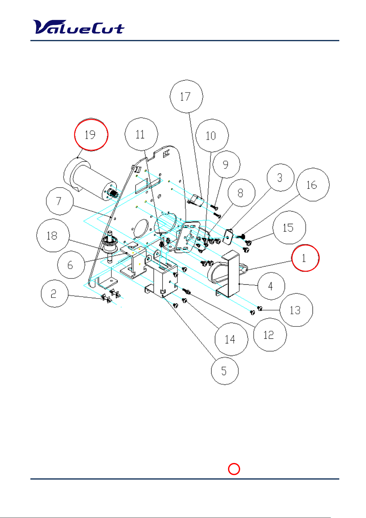
Page 8
MAINTENANCE MANUAL
: Recommend Service Parts
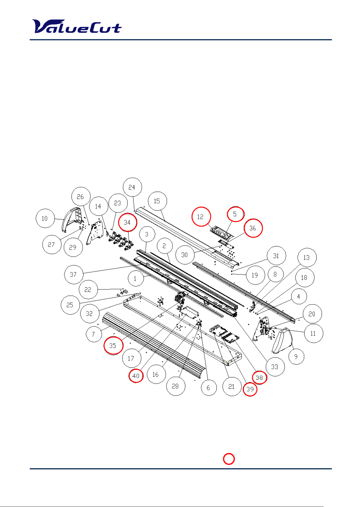
Exploded View
Please use the following exploded view as a reference when selecting the parts.
The recommended service parts are circled in red. Please refer to the parts list at the end of this manual
for the parts number and parts names.
A. Main Unit Assembly
VC2E-MM-00
8
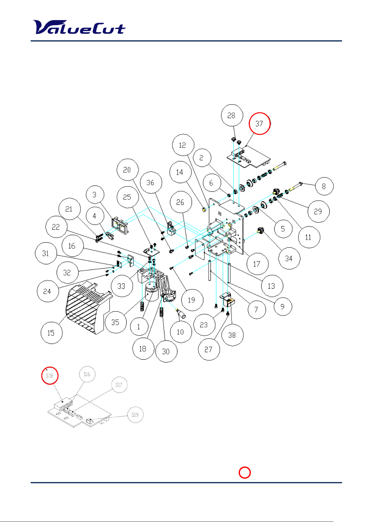
Page 9
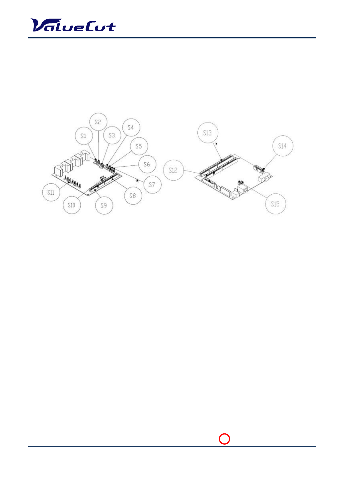
B. Electronic and Electrical Assembly
: Recommend Service Parts
MAINTENANCE MANUAL
VC2E-MM-00
9
Page 10
C. Left End Assembly
: Recommend Service Parts
MAINTENANCE MANUAL
VC2E-MM-00
10
Page 11
D. Right End Assembly
: Recommend Service Parts
MAINTENANCE MANUAL
VC2E-MM-00
11
Page 12

E. X Motor Bracket and Belt Assembly
: Recommend Service Parts
MAINTENANCE MANUAL
VC2E-MM-00
12
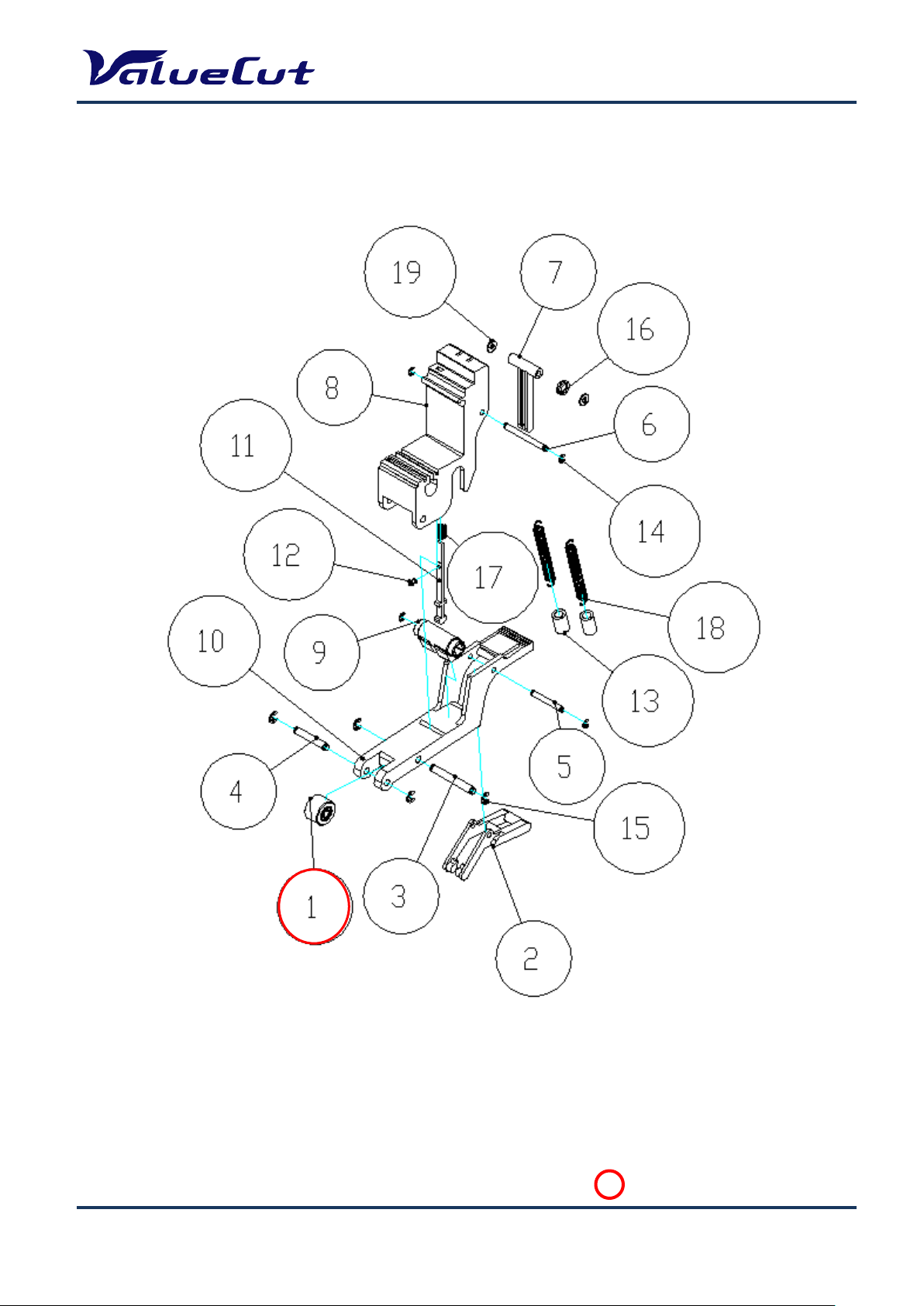
Page 13
F. Carriage Assembly
: Recommend Service Parts
MAINTENANCE MANUAL
VC2E-MM-00
13
Page 14
G. Pinch Roller Assembly
: Recommend Service Parts
MAINTENANCE MANUAL
VC2E-MM-00
14
Page 15
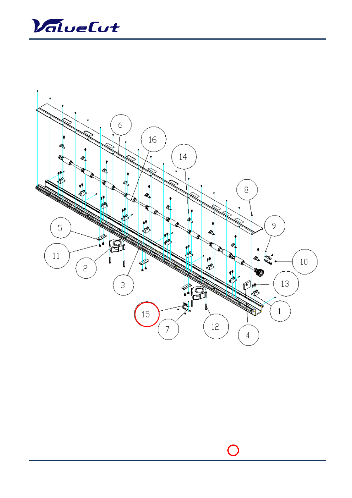
: Recommend Service Parts
H. Main Beam Assembly
MAINTENANCE MANUAL
VC2E-MM-00
15
Page 16
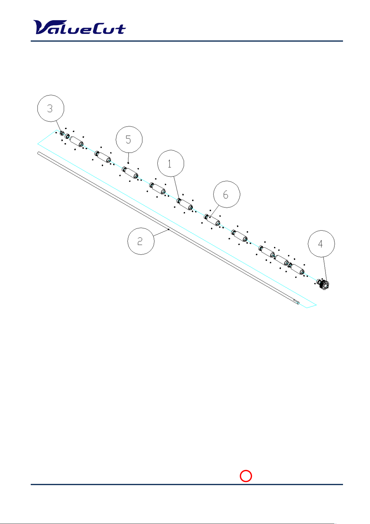
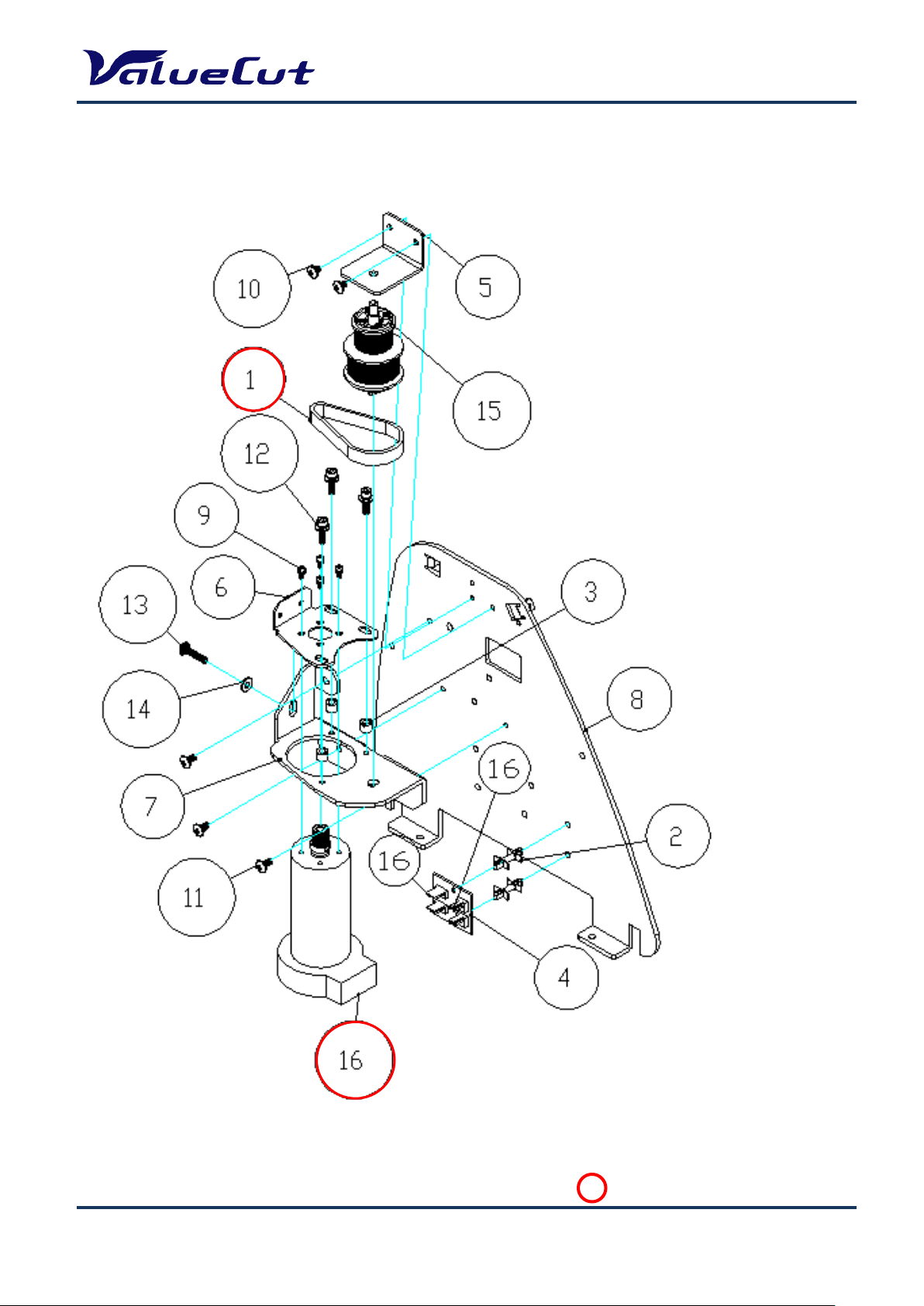
I. Drum Assembly
: Recommend Service Parts
MAINTENANCE MANUAL
VC2E-MM-00
16
Page 17
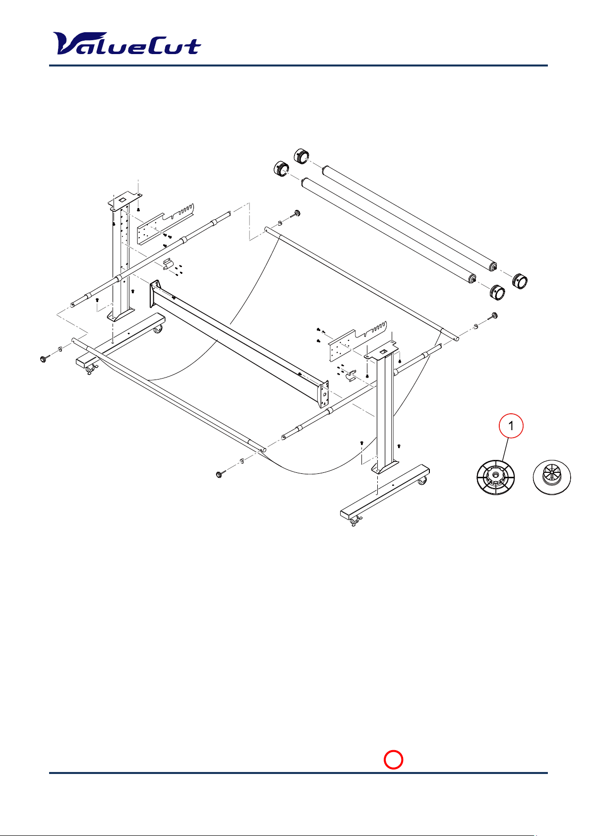
J. Stand and Basket
: Recommend Service Parts
MAINTENANCE MANUAL
VC2E-MM-00
17
Page 18
System Diagram and Wiring Diagram
MAINTENANCE MANUAL
VC2E-MM-00
18
Page 19

System Diagram
OSC 54MHzOSC 54MHz
CPU
54MHz
MCF5206EAB54
FLASH
512KBx2 or 512KBx3
DRAM
1MB or 4MB
SRAM
64KB
TIMER & PWM
Generator
TIMER & PWM
Generator
X Motor
Driver
Y Motor
Driver
VCM
Driver
X Motor
Encoder
Y Motor
Encoder
VCM
Encoder
LCM
Display
USB
Port
Serial
Port
Media
Sensor (x2)
Carriage
Sensor
Lever
Sensor
Memory
FPGA
MAINTENANCE MANUAL
VC2E-MM-00
19
Page 20

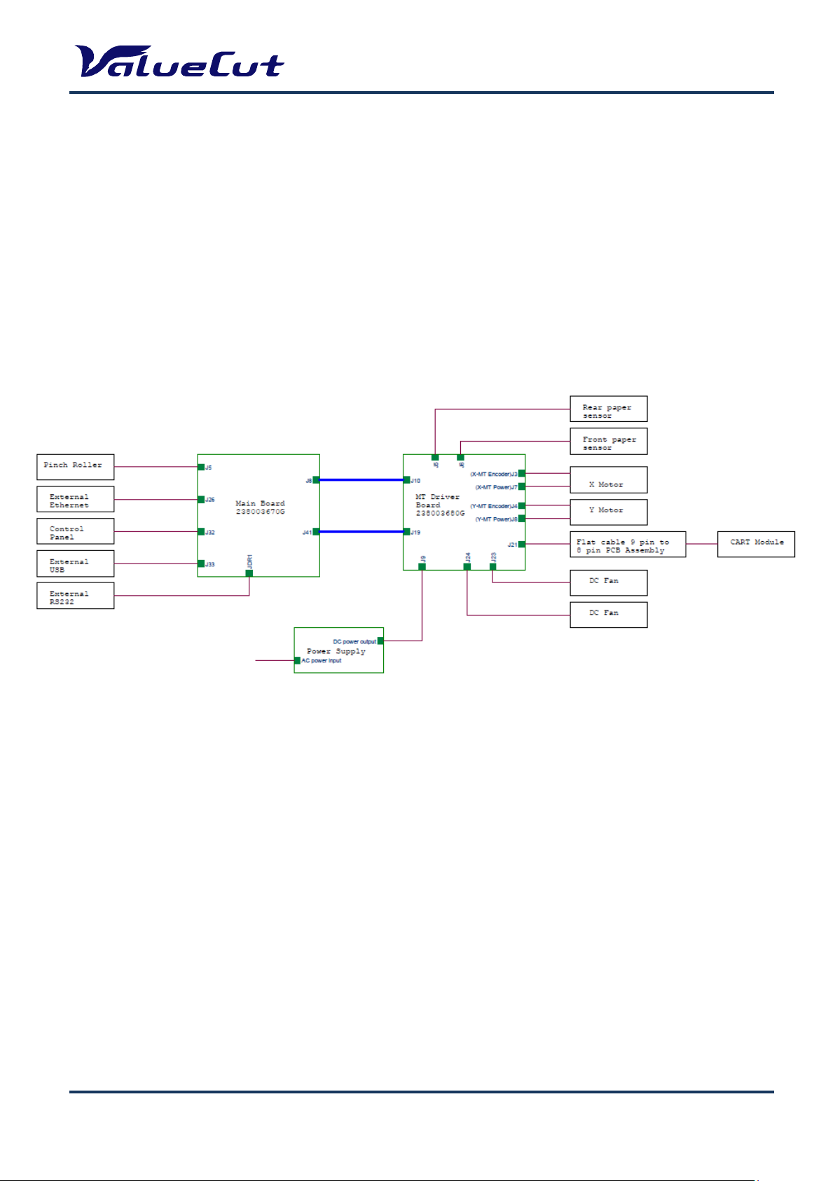
Wiring Diagram - Main Board
Main board
Port
Connected to
J5
Pinch Roller switch
J8
20x2 Ribbon Cable connect to Motor Drive Board J10
J26
External Ethernet Port
J32
Control Panel
J33
External USB Port
J41
20x2 Ribbon Cable connect to Motor Drive Board J19
JDR1
External RS-232C Port
MAINTENANCE MANUAL
VC2E-MM-00
20
Page 21
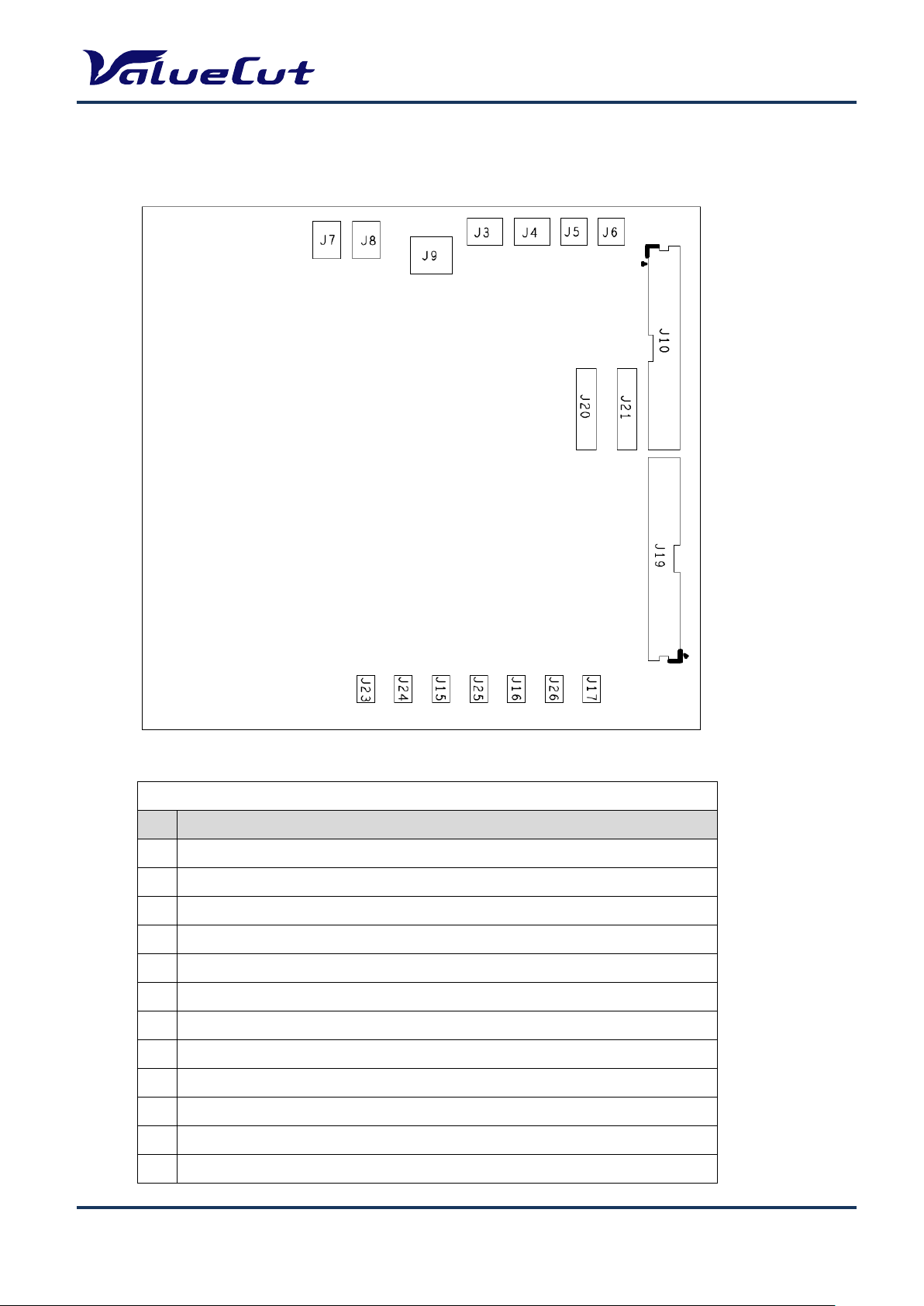
Wiring Diagram - Driver Board
Driver board
Port
Connected to
J3
X Motor encoder
J4
Y Motor encoder
J5
Rear paper sensor
J6
Front paper sensor
J7
X Motor power
J8
Y Motor power
J9
DC Power input
J10
20x2 Ribbon Cable connect to Main Board J8
J19
20x2 Ribbon Cable connect to Main Board J41
J21
Flat cable connect to Flat cable 9 pin to 8 pin PCB Assembly
J23
DC FAN
J24
DC FAN
MAINTENANCE MANUAL
VC2E-MM-00
21
Page 22

MAINTENANCE MANUAL
1. Remove the side cover screws.
2. Put equal pressure on both sides of the
side cover and pull to remove.
1. Remove the 7 front cover screws and 7 back cover screws.
The procedure to remove Side cover R is the same as
that of Side cover L. The pictures used here are of Side
cover L.
Maintenance
This chapter explains the parts replacement and maintenance of the ValueCut Cutting Plotter. It gives
detailed step-by-step instruction on how to replace or adjust the components of this machine.
Parts Replacement
Removing Covers
Please follow the steps below to remove the front, back, side and top covers.
Side Cover:
Front and Back Cover:
VC2E-MM-00
22
Page 23

3. Remove the 2 front cover screws and 2 back cover screws.
1. Disconnect the panel cable and FG cable.
(No need to remove the screws securing FG cable)
2. Remove the panel cable and FG cable from
the clamp.
Top Cover:
MAINTENANCE MANUAL
VC2E-MM-00
23
Page 24

1. Lower the lever.
(Reference: Pinch rollers are down)
4. Lift the Top cover vertically to remove.
(Reference: Pinch rollers are up)
Make sure not to damage the sensor-flag when lifting
the Top cover.
MAINTENANCE MANUAL
Replacing Pinch Roller Sets
Please follow the steps below to replace the pinch roller sets.
VC2E-MM-00
24
Page 25

MAINTENANCE MANUAL
2. Remove the 2 bracket screws.
3. Remove the bracket and washer.
4. Slide the pinch roller set to the right end of
the Square Bar.
5. Remove the pinch roller set through the
notch.
VC2E-MM-00
25
Page 26

MAINTENANCE MANUAL
Cam Roller
Release Grip
Color-code
1. Depress the locking clips at the top of the tool carriage cover, and pull the cover away.
(It is easy to remove if you lift from the bottom)
Note: When re-installing the Pinch roller set, the Cam roller must be aligned squarely to the Square Bar.
Note: When aligning the Cam roller, please remember to keep the release grip locked down.
Note: Pinch-roller is color-coded by pressure force. When replacing
the pinch-roller, make sure to replace all the pinch-rollers
with the same color.
Replacing Carriage Board
Please follow the steps below to replace the carriage board.
VC2E-MM-00
26
Page 27

MAINTENANCE MANUAL
1: Install the carriage board in the reverse order of removal.
2: Need to replace the tool carriage or flat cable if the Pinch
Roller Sensor is still not effective after the replacement.
2. Disconnect the 4 cables connected to
the carriage board.
3. Remove the 2 screws securing the
carriage board.
Make sure to install the carriage board so that the
sensor-flag is in the middle of the sensor.
Be careful not to damage the aluminum tape as it is reused.
VC2E-MM-00
27
Page 28

Replacing Tool Carriage
1. Loosen the 2 retaining screws (No need to remove them), and then turn
the 2 adjustment screws anti-clockwise to loosen the carriage belt.
Adjustment Screws
Retaining Screws
2. Pop up the plastic locking pins using a
flathead screwdriver.
3. Pull out the cable lock, and remove
the belt.
Nut A
5. Loosen the Bolt B.
Bolt B
4. Remove the Nut A.
Please follow the steps below to replace the tool carriage.
MAINTENANCE MANUAL
VC2E-MM-00
28
Page 29

MAINTENANCE MANUAL
6. Make a space between the rollers as shown
in the figure above.
You can loosen the bolt easily by putting your fingers
between the rollers.
7. Remove the roller under the cursor from the
rail, and then remove the cursor.
Install the tool carriage in the reverse order of removal.
Be careful not to drop off the spacer when
removing the roller.
VC2E-MM-00
29
Page 30

Replacing Y-Motor
3. Disconnect the 2 cables connected to
the motor.
4. Remove the 4 screws securing the Y-motor.
1. Loosen the 3 retaining screws securing
the bracket. (No need to remove them)
2. Loosen the tension adjustment screw.
(No need to remove them)
1: Install the Y-motor in the reverse order of removal.
2: Belt tension adjustment is required after the
replacement.
For details, refer to “Belt Tension Adjustment”.
3: Please connect the cables to the Y-motor after the
belt tension adjustment is completed.
5. Remove the Y-motor.
Please follow the steps below to replace the Y-motor.
MAINTENANCE MANUAL
VC2E-MM-00
30
Page 31

Replacing X-Motor
1. Loosen the 4 retaining screws securing
the bracket. (No need to remove them)
2. Loosen the tension adjustment screw.
(No need to remove them)
4. Remove the 4 screws securing the X-motor.
5. Remove the X-motor.
3. Disconnect the 2 cables connected to the
motor.
1: Install the X-motor in the reverse order of removal.
2: Belt tension adjustment is required after the
replacement.
For details, refer to “Belt Tension Adjustment”.
3: Please connect the cables to the X-motor after the
belt tension adjustment is completed.
Please follow the steps below to replace the X-motor.
MAINTENANCE MANUAL
VC2E-MM-00
31
Page 32

Replacing Main Board
1. The main board is installed at the right
end.
2. Remove the 5 cables and 4 screws.
1: Install the Main board in the reverse order of
removal.
2: Need to remove the X-motor first to remove the
screws on the main board.
3. Remove the main board.
Please follow the steps below to replace the main board.
MAINTENANCE MANUAL
VC2E-MM-00
32
Page 33

Replacing Driver Board
1. The driver board is installed in the
middle.
2. Remove the 10 cables and 4 screws.
3. Remove the driver board.
Install the Driver board in the reverse order of
removal.
Please follow the steps below to replace the driver board.
MAINTENANCE MANUAL
VC2E-MM-00
33
Page 34

Replacing Power Supply board
1. The power supply board is installed at
the left side.
2. Remove the 2 cables and 4 screws.
3. Remove the power supply board.
Install the Power supply board in the reverse
order of removal.
Please follow the steps below to replace the power supply board.
MAINTENANCE MANUAL
VC2E-MM-00
34
Page 35

Replacing Fuses
1. Hold the both clips by applying equal pressure on the fuse
housing, and push the fuse out.
Handling clip
The position of fuse (inlet switch) is different
depending on the model.
Please follow the steps below to replace fuses.
MAINTENANCE MANUAL
VC2-600/1300: Left side VC2-1800: Right side
VC2E-MM-00
35
Page 36

MAINTENANCE MANUAL
Port to use
USB port
Serial port
Operation
[Down] key + Power on
[CUT TEST] key + Power on
Step 1. Check if the port displayed on the "ValueCut File Uploader" window is correct.
Step 2. Select the firmware file on the dialog box, and click Start.
Step 3. If the update is completed, the machine is automatically restarted in normal mode.
Firmware Update
After replacing Main board, it is necessary to update firmware to latest version.
Please follow the steps below to update firmware.
Note1: Make sure to use the latest version of ValueCut File Uploader.
Note2: There are different firmware versions depending on the ValueCut size.
When you replace the main board for the firmware update or repair, please make sure to upload
the appropriate firmware.
Note: After the firmware installation, please perform “Backup of Settings” and “Restoration of Settings”.
Note: Write down all the setting values before performing initialization. Enter the values again from the
panel after initialization is done. (“AAS Offset X/Y” and “Scale Length/Width” values will be
backed-up, so resetting will not be required.)
VC2E-MM-00
36
Page 37

Backup of Settings
x2
Tips for pressing both buttons at the same time:
Press the CUT TEST key first, and then press the
ON/OFF Line key.
1
2
Make the backup of "AAS Offset X/Y" and "Scale Length/Width".
When updating the firmware, all setting except these values will be initialized.
In Offline mode, Press TOOL SELECT key to enter the tool setting menu.
Click the right arrow key twice to display the restore menu.
MAINTENANCE MANUAL
Press CUT TEST key and ON/OFF LINE key at the same time.
Press ENTER key.
VC2E-MM-00
37
Page 38

MAINTENANCE MANUAL
x2
Press ENTER key.
Note: Only "AAS Offset X/Y" and "Scale Length/Width" can be backed-up.
Note: If you want to initialize the backup value, please go to Initialization of Settings
Initialization of Settings
Completely initialize all the settings including the backup value of "AAS Offset X/Y" and "Scale
length/Width".
In Offline mode, Press TOOL SELECT key to enter the tool setting menu.
Click the right arrow key twice to display the restore menu.
VC2E-MM-00
38
Page 39

Tips for pressing both buttons at the same time:
Press the CUT TEST key first, and then press the
ON/OFF Line key.
1
2
Press CUT TEST key and ON/OFF LINE key at the same time.
Press ENTER key.
MAINTENANCE MANUAL
Press DATA CLEAR key.
Press ENTER key then all the setting values will be initialized.
Turn off the power after initialization.
VC2E-MM-00
39
Page 40

Restoration of Settings
Return to the default value except backed-up values.
In Offline mode, Press TOOL SELECT key to enter the tool setting menu.
Click the right arrow key twice to display the restore menu.
MAINTENANCE MANUAL
Press ENTER key then all the setting values will be initialized.
Turn off the power after initialization.
VC2E-MM-00
40
Page 41

Factory Default Parameter
Factory default parameter information is attached under the machine.
MAINTENANCE MANUAL
Below are the items for setup. Numbers shown in each parenthesis below are the example numbers of
this machine (Serial# EVC5U0247).
AAS Offset (X= -1.6, Y= 0.3)
Scale Length (Length: 500 / 496 mm)
Width Length (Width: 500 / 500 mm)
AAS Offset Setup
Step 1. Press the MICS key in Offline mode to enter Setup menu.
Step 2. Click [< or >] key to display “AAS Offset”, and press the Enter key.
Step 3. Enter the X value shown on the Parameter Record Card.
Step 4. Click [>] key, and enter the Y value shown on the Parameter Record Card.
Step 5. Click Enter.
Scale Setup
Step 1. Press the MICS key in Offline mode to enter Setup menu.
Step 2. Click [< or >] key to display “Scale Length X (Y)”, and press the Enter key.
Step 3. Click [<] key, and change the left number to [500].
Step 4. Click [>] key, and change the right number to the value shown on the Parameter Record Card.
Step 5. Click Enter.
Note: The machine setting conditions may have been changed from the factory default, please check the
On-line data to confirm the final machine settings.
VC2E-MM-00
41
Page 42

MAINTENANCE MANUAL
1. Move the tool carriage to the far left
end of the guide beam.
2. Loosen the 2 retaining screws on the top
of the carriage belt roller housing.
3. Place the belt tension gauge at the
center of the belt, and measure the belt
tension.
4. To adjust the belt tension, adjust the
screws on the side of the carriage belt
roller housing.
To tighten the tension, turn the screws
clockwise. To loosen the tension, turn
the screws anticlockwise.
1: The desirable tension is as follows:
VC2-600 650g - 850g
VC2-1300 220g - 320g
VC2-1800 180g - 200g
2: Tighten the upper and lower screws evenly to
secure the belt in the proper position.
3: Tighten the 2 retaining screws on the top of the
housing once the adjustment is made.
Belt Tension Adjustment
Tool Carriage Belt
After replacing the tool carriage belt or belt itself, the belt adjustment is required. Please follow the
procedure below.
VC2E-MM-00
42
Page 43

X Motor Belt
3. Hook the push-pull gauge into the hole of X
motor bracket, and pull toward yourself along
the direction parallel to the X-motor belt.
The pulling force is 2kgf.
1. Loosen the 4 retaining screws
securing the X-motor bracket.
4. Tighten the 4 retaining screws securing
the X-motor bracket.
5. Tighten the tension retaining screw.
2. Loosen the tension retaining screw
of X motor bracket.
The tension between the drum and X motor is 2 kgf.
MAINTENANCE MANUAL
VC2E-MM-00
43
Page 44

Y Motor Belt
4. Tighten the 3 retaining screws securing
the Y-motor bracket.
3. Hook the push-pull gauge into the hole of
Y motor bracket, and pull toward yourself
along the direction parallel to the Y-motor
belt. The pulling force is 2kgf.
5. Tighten the tension retaining screw.
1. Loosen the 3 retaining screws securing
the bracket.
2. Loosen the tension retaining screw of
Y motor bracket.
The tension between the drive pulley and Y
motor is 2 kgf.
MAINTENANCE MANUAL
VC2E-MM-00
44
Page 45

MAINTENANCE MANUAL
Troubleshooting
Maintenance Diagnostics
This section describes the maintenance diagnostics as troubleshooting. This diagnostic feature is to
check hardware to find out which components are good or defective. Using this diagnostic test facility
enables the diagnosing of hardware components.
How to Start Maintenance Diagnostics
To start the Maintenance Diagnostics, Press and hold down the On/Off Line key and the CUT TEST key
while turning on the machine. The following sub-sections will explain the function of each maintenance
diagnostic sequence.
VC2E-MM-00
45
Page 46

[<] key
システム(LCD が流れている3秒
間)はテストをすることができま
せん。
[>] key
[<] key
[>] key
[<] key
[>] key
[<] key
[>] key
[<] key
[>] key
[<] key
[>] key
[<] key
[>] key
[<] key
[>] key
[<] key
[>] key
[<] key
[>] key
Cancel
key
[>] key
[<] key
[>] key
System cannot go on testing, LCD
displays a message more than 3
seconds.
Diagnostics Function Diagram
MAINTENANCE MANUAL
VC2E-MM-00
46
Page 47

MAINTENANCE MANUAL
ENTER key
ON/OFF LINE key
or
Lever sensor
Diagnostic Test for SRAM and DRAM
This test provides the ability to diagnose the SRAM and DRAM. If these two components are bad, replace
them. Otherwise the cutting plotter will not work properly.
Diagnostic Test for Lever Sensor
It diagnoses the lever sensor. If the sensor is faulty, the cutting plotter cannot sense if the pinch rollers
have been lowered or not. If the lever sensor is down, the LCD displays “DOWN”. If the lever sensor is up,
the LCD displays “UP”. To return to the previous menu, Press the ON/OFF LINE key.
VC2E-MM-00
47
Page 48

MAINTENANCE MANUAL
or
ENTER key
ON/OFF LINE key
Paper sensor
Diagnostic Test for Media Sensors
It diagnoses the media sensors. If they are faulty, the cutting plotter cannot detect the media length
correctly. The current condition of front and rear sensor will be displayed on the LCD. You can check if the
sensors are working correctly by turning it on or off.
VC2E-MM-00
48
Page 49

MAINTENANCE MANUAL
or
ENTER key
ON/OFF LINE key
Width detection sensor
Sensor Flag
Diagnostic Test for Width Sensor
It diagnoses the width sensor. If the sensor is faulty, the cutting plotter cannot detect the media width
correctly. You can check the sensor by moving the tool carriage to the left and right. When moving the tool
carriage close to the pinch roller, the message on the LCD changes quickly to on and off. For replacement,
please refer to the maintenance chapter.
VC2E-MM-00
49
Page 50

MAINTENANCE MANUAL
ENTER key
ON/OFF LINE key
3 seconds later
ENTER key
ON/OFF LINE key
3 seconds later
Diagnostic Test for Motor Encoder and Tool Holder Encoder
It diagnoses the X and Y motor encoder and tool holder encoder. If the encoder is defective, the cutting
plotter cannot work properly. To check if the encoder is bad or good, you can apply a slight force to the
tested part (such as a drum, tool carriage or tool holder) then examine the readings. If the encoder
reading changes dramatically or does not change at all, the encoder is bad. To replace the motor or tool
carriage, please refer to the maintenance chapter.
X Motor Encoder Test
Y Motor Encoder Test
VC2E-MM-00
50
Page 51

MAINTENANCE MANUAL
ENTER key
ON/OFF LINE key
3 seconds later
Holder Encoder Test
VC2E-MM-00
51
Page 52

MAINTENANCE MANUAL
ENTER key
ON/OFF LINE key
Forward key
Backward key
Diagnostic Test for Motor Movement
It diagnoses the X and Y motors and drivers. If you encounter a motor movement problem, try to change
the main board first. If the problem still remains after replacing the main board, try replacing the motor.
Drum Movement
VC2E-MM-00
52
Page 53

MAINTENANCE MANUAL
ENTER key
ON/OFF LINE key
Right key
ENTER key
ON/OFF LINE key
ENTER key
ON/OFF LINE key
Left key
Carriage Movement
Holder Movement
VC2E-MM-00
53
Page 54

Diagnostic Test for Interface
ENTER key
ENTER key
ENTER key
ENTER key
ON/OFF LINE key
ON/OFF LINE key
ON/OFF LINE key
ON/OFF LINE key
This is a function that is not normally used in maintenance work.
Check RS-232 9600
Check RS-232 19200
MAINTENANCE MANUAL
Check Printer Port
Check USB port
VC2E-MM-00
54
Page 55

MAINTENANCE MANUAL
Problems and Solutions
This section describes the typical problems you may encounter while operating the cutting plotter and
offers you possible solutions.
The cutting quality is not good at the corner or the end point.
[Check item] [Action]
Is the screw on holder loose? Tighten the screw firmly.
Is the blade worn? Replace the blade.
Is AAS offset value adjusted? Adjust the offset value.
Is the media not flat enough? Reload the media.
Is the media wet? Replace the media.
Is the quality of media not good? Change the media.
Is the drum or pinch roller worn? Replace the drum set or pinch roller.
The media width cannot be detected since the pinch roller position is not clear.
[Check item] [Action]
Is the pinch roller lowered? Lower the lever and release the lock.
Is the width sensor working? Adjust the board mounting position.
Is the width sensor covered the flag? Check the board mounting position.
Is the flat cable damaged? Replace the cable.
Is the width sensor damaged? Replace the carriage board.
Is the carriage board damaged? Replace the carriage board.
The function of "Set New Origin" does not work.
[Action]
Set a media on the ValueCut, and Press ENTER key when LCD displays the X/Y distance from the old
origin.
VC2E-MM-00
55
Page 56

MAINTENANCE MANUAL
Media shifts away when plotting a long drawing.
[Check item] [Action]
Is the media aligned accurately? Reload the media.
Is the media pre-run with Jog key? Reload the media and pre-run.
Is the media edge cut straightly? Change the media.
Is the media too thin? Change the media.
Is there any paper chips or dust on the drum? Clean the surface of drum.
Is the drum or pinch roller worn? Replace the drum set or pinch roller.
The cutting line is wavy.
[Check item] [Action]
Is the screw on holder loose? Tighten the screw firmly.
Is the blade worn? Replace the blade.
Is the acceleration set too high? Set the acceleration to a lower value.
Is the carriage belt tension correct? Adjust the belt tension.
Is X or Y motor belt tension correct? Adjust the belt tension.
Is the carriage bearing or roller damaged? Replace the carriage.
Is the media length too short in X direction? Change the media.
Is the media too thin? Change the media.
Is the drum or pinch roller worn? Replace the drum set or pinch roller.
Is X or Y motors damaged? Replace the motor.
Data are missing when plotting.
[Check item] [Action]
The memory chip may have a problem. Replace the main board.
Serious error occurs when feeding media.
[Check item] [Action]
Are some media pulled out from the roll? Enable “Auto media feed” on the panel.
Is X motor belt too tight? Adjust the belt tension.
VC2E-MM-00
56
Page 57

MAINTENANCE MANUAL
Static electricity is generated.
[Check item] [Action]
Is the ground connection correct? Connect the ground correctly.
The carriage is locked and cannot move.
[Check item] [Action]
Is the carriage bearing or roller damaged? Replace the carriage.
Is the carriage belt too tight? Adjust the belt tension.
Is the carriage belt loose since some screws are not tight? Tighten the screws.
The keyboard does not work.
[Check item] [Action]
Is the connection between keyboard and mainboard bad? Re-plug or replace the keyboard.
Is there dust or mist on the keyboard surface? Replace the keyboard set.
Abnormal noise occurs during standby mode.
[Check item] [Action]
Are there any loose screws? Tighten the screws firmly.
Is X or Y motor belt tension correct? Adjust the belt tension.
Is the carriage belt tension correct? Adjust the belt tension
Is the driver damaged? Replace the main board.
Abnormal noise occurs from the drum during operation.
[Check item] [Action]
Is X or Y motor belt loose? Adjust the belt tension.
Is the driver damaged? Replace the main board.
Is the drive gear at the drum tightly mounted on the shaft? Replace it.
Are the screws securing the drum to the shaft loose? Tighten the screws firmly.
Is X or Y motor damaged? Replace the X or Y motor.
VC2E-MM-00
57
Page 58

MAINTENANCE MANUAL
The tool carriage does not move up/down.
[Check item] [Action]
Is the blade holder installed properly? Refer to user’s guide and reinstall the holder.
Is the flat cable damaged? Replace the flat cable.
Is the carriage board damaged? Replace the carriage board.
Is the carriage damaged? Replace the carriage set.
Is the encoder of carriage damaged? Replace the carriage set.
Is the driver damaged? Replace the main board.
Is the linear bearing shaft of carriage rusty? Replace the carriage set.
Some unexpected lines are plotted.
[Check item] [Action]
Is the blade holder installed properly? Refer to user’s guide and reinstall it.
Is the media warp? Or are there some bubbles? Re-load the media or replace if needed.
Is the vacuum fan working? Replace the fan or main board.
Does the tool carriage move up/down? Please refer to the previous item.
Is the output command HPGL or HPGL/2? Ask your software agent for help.
Are there some communication errors? Check the communication protocol.
The cutting force is not applied correctly.
[Check item] [Action]
Is the cutting force set properly? Reset the cutting force on panel or with command.
Is the blade length out of the holder too short? Re-load the blade and readjust.
Does the cutter holder move smoothly? Change the carriage set.
Is there any problem on the holder encoder? Change the carriage set.
VC2E-MM-00
58
Page 59

MAINTENANCE MANUAL
Media drops sometimes.
[Check item] [Action]
Is the media loaded askew? Reload the media.
Is the pinch roller set on the top of drum? Move the pinch roller to a right position.
Is the edge of media damaged? Change the media.
Is the media cut straight across? Cut the media evenly and reload the media.
Is the media too thin? Change the media.
Is the drum or pinch roller worn? Replace the drum set or pinch roller.
VC2E-MM-00
59
Page 60

MAINTENANCE MANUAL
Error
Event/Symptom
Troubleshooting
Media detection failed
Are Pinch Rollers installed correctly?
Check the width sensor in self-diagnosis.
<Parts may be broken>
AASII carriage board Assy
Watch dog-Interface converter board Assy
Main board Assy
Flat cable Assy
Media detection failed
Are Pinch Rollers installed correctly?
Check the width sensor in self-diagnosis.
<Parts may be broken>
AASII carriage board Assy
Watch dog-Interface converter board Assy
Main board Assy
Flat cable Assy
Media detection failed
Are Pinch Rollers installed correctly?
Check the width sensor in self-diagnosis.
<Parts may be broken>
AASII carriage board Assy
Watch dog-Interface converter board Assy
Main board Assy
Flat cable Assy
Abnormal condition in PF motor
(X-axis)
Remove the obstacle that prevents the X-axis
operation.
Check if a media is jammed on the machine.
Check "X Encoder" and "Drum Movement" in
self-diagnosis.
<Parts may be broken>
X-motor
Main board Assy
Error Message and Handling
Serious Error
This section describes the contents of reboot-required errors as well as the check items and recovery
actions.
VC2E-MM-00
60
Page 61

MAINTENANCE MANUAL
Abnormal condition in CR motor
(Y-axis)
Remove the obstacle that prevents the Y-axis
operation.
Check "Y Encoder" and "Carriage Movement"
in self-diagnosis.
<Parts may be broken>
Y-motor
Main board Assy
Error on UP/DOWN pen operation
Adjust length of the cutter blade.
Remove the obstacle that prevents the
UP/DOWN operation
Check if a media is jammed on the machine.
Check “Holder Encoder” and “Holder
Movement” in self-diagnosis.
<Parts may be broken>
AASII carriage board Assy
Watch dog-Interface converter board Assy
Main board Assy
Flat cable Assy
AAS detection failed
Check print quality for “Reg mark”
Adjust the scale properly.
<Parts may be broken>
Carriage Assy
Error
Event/Symptom
Troubleshooting
Media detection failed
Switch the Pinch Roller enabled.
Receive undefined command
Check the data send from computer.
Connection error on RS-232C port
Set the communication condition.
Data on the out of print range
Send the data within print range.
AAS data exceeds 4MB
Edit AAS data to be less than 4MB.
Operation Error
This section describes the contents of errors with messages as well as the check items and recovery
actions. These messages are displayed when an abnormal condition occurs during operation.
VC2E-MM-00
61
Page 62

Appendix
Part no.
Part name
VC2-600
VC2-1300
VC2-1800
Location
ML-10042
Control Panel Board Assy for VC2
V V V
A-36
ML-10043
Control Panel Sticker for VC2
V V V
A-5
ML-10005
Motor Assy
V V V
C-16, D-19
E-1
ML-10009
Pinch Roller Assy
V V V
A-34
ML-10047
Carriage Board Assy for VC2
V V V
F-37
Recommend Service Parts List
MAINTENANCE MANUAL
VC2E-MM-00
62
Page 63

MAINTENANCE MANUAL
Part no.
Part name
VC2-600
VC2-1300
VC2-1800
Location
ML-10044
Flat Cable Assy for VC2-6
V
F-S18
ML-10045
Flat Cable Assy for VC2-13
V
F-S18
ML-10046
Flat Cable Assy for VC2-18
V
F-S18
ML-10012
Paper Sensor Assy_VC6/VC13
V
V
H-15
ML-10013
Paper Sensor Assy_VC18
V
H-15
VC2E-MM-00
63
Page 64

MAINTENANCE MANUAL
Part no.
Part name
VC2-600
VC2-1300
VC2-1800
Location
ML-10016
Carriage Assy_VC6/VC13 (without CR
Board)
V
V
A-35
ML-10017
Carriage Assy_VC18 (without CR Board)
V
A-35
ML-10018
Power Supply Board Assy
V V V
A-40
ML-10048
Main Board Assy for VC2
V V V
A-38
ML-10035
Driver Board Assy
V V V
A-39
VC2E-MM-00
64
Page 65

MAINTENANCE MANUAL
Part no.
Part name
VC2-600
VC2-1300
VC2-1800
Location
ML-10021
Pinch Roller Wheel
V V V
G-01
ML-10023
X-axis Belt (2GT-L240-W10)
V
D-01
ML-10024
Y-axis Belt (2GT-L172-W10)
V V V
C-1
ML-10025
Roller Holder Flange (2pcs)
(2pcs/box)
V V V
J-1
ML-10039
Media Feed Lever
V V V
A-13
ML-10040
Media Feed Lever Cam
(with screw)
V V V
A-11/20
VC2E-MM-00
65
Page 66

Specification
Model Number
VC2-600
VC2-1300
VC2-1800
Operation Method
Paper Moving Type
Max. Cutting Width
610mm(24in)
1320mm(52in)
1830mm(72in)
Max. Cutting Length
50m(164ft)
Max. Media Loading Width
770mm(30.3in)
1594mm(62.7in)
1990mm(78.3in)
Min. Media Loading Width
50mm(1.97in)
300mm(11.8in)
Number of Pinch Rollers
3 4 6
Acceptable Material Thickness
0.8mm(0.03in)
Drive Motor
DC Servo Control
Cutting Force
5~600 g
Max. Cutting Speed
1530 mm/sec
Max. Acceleration
4.2 G
Blade Offset
0~1.0 mm (0.025mm/step)
Memory Buffer
32 MB/16MB (when using AAS)
Interface
USB 2.0 (Full speed), Serial (RS-232C) and Ethernet
Type of Command
HP-GL, HP-GL/2
Mechanical Resolution
0.006mm
Software Resolution
0.025 mm
Distance Accuracy
±0.254 mm or ±0.1% of move, whichever is greater
Repeatability
±0.1mm
Curve & Arc Smoothing
Yes
Configurable Origin
Yes
Test Cut capability
Yes
Tangential
Yes
Repeat
Yes
Copy
Yes
Pouncing
Yes
Automatic-Aligning System
AASII
Control Panel
LCD (20 digits x 2 lines), 14 keys, 1 Power LED
Power Supply
AC 100-240V, 50~60 Hz (Auto switching)
Power Consumption
110 W
Dimension (HxWxD) mm
412 * 950 * 486
1111 * 1774 * 651
1127 * 2170 * 756
Net Weight
18 kg
50 kg
63 kg
Stand
Optional
Standard
Media Basket
Optional
Standard
Operation
Environment
Temperature
15 ゚ C ~ 30 ゚ C, 60 ゚ F ~ 86 ゚ F
Humidity
25% ~ 75%
MAINTENANCE MANUAL
The specification and data sheet may vary with different materials used. In order to obtain the best
output quality, please maintain the machine regularly and properly.
MUTOH reserves the right to change the specifications at any time without notice.
The above listed specification values are effective only when operated with media certified by
MUOTH.
VC2E-MM-00
66
Page 67

Consumable Item List
Item Number
Item Name
VC-CHD
Cutting Blade Holder
VC2-CBRE1
Cutting Blade Red Cap (45 ゚ 0.25) (1pcs/box)
VC2-CBGR1
Cutting Blade Green Cap (60 ゚ 0.5) (1pcs/box)
VC2-CBBU1
Cutting Blade Blue Cap (60 ゚ 0.25) (1pcs/box)
VC2-CBBK1
Cutting Blade Black Cap (42 ゚ 0.175) (1pcs/box)
VC2-CBYE5
Cutting Blade Yellow Cap (25 ゚ 0.25) (1pcs/box)
VC-CMAT
Cutting Pad (6mmx10m)
VC-TW
Tweezers (L=11cm, W=0.85cm)
VC-SB
Safe Blade
Item Number
Item Name
VC2-STD600
Stand for VC-600
VC-TBL
Add-on flat table for VC-600
VC-RS
RS-232 Cable (25pin)
VC-USB
USB Cable
VJ-AC15SJ
AC Cable (Japanese Safety Standard)
VJ-AC15SA
AC Cable (North America Safety Standard)
VJ-AC10SE
AC Cable (European Safety Standard)49
MAINTENANCE MANUAL
Optional Item List
VC2E-MM-00
67
Page 68

MUTOH INDUSTRIES LTD.
Tel:81-(0)3-6758-7030
Fax:81-(0)3-6758-7021
E-mail:cs_service@mutoh.co.jp
http://www.mutoh.co.jp/en/
MUTOH AMERICA INC.
Tel:+1-480-968-7772
Fax:+1-480-968-7990
E-mail:sales@mutoh.com
http://www.mutoh.com/
MUTOH Europe nv
Tel:32-(0)59-561400
Fax:32-(0)59-807117
E-mail:mutoh@mutoh.be
http://www.mutoh.eu/
MUTOH DEUTSHLAND GmbH
Tel:49-(0)211-385474-0
Fax:49-(0)211-385474-74
E-mail:vertrieb@mutoh.de
http://www.mutoh.de/
MUTOH North Europe S.A.
Tel:352-2702-3045
Fax:352-2644-0469
E-mail:info@mutohnorth.eu
http://www.mutohnorth.eu/
MUTOH AUSTRALIA PTY.LTD.
Tel:61-2-9437-1366
Fax-61-2-9436-2871
E-mail:sales@mutoh-au.com/
http://mutoh-au.com/
 Loading...