

Page 1
MF-1100
Thank you for buying the Value 3D MagiX MF-1100. Please read
this manual before using this products for long term usage. This
product has been adjusted before shipment from the factory.
OPERATION
MANUAL
Page 2

2
[Warranty Regulations]
■Repairs shall be charged for in the following cases even during the warranty period.
(a) Malfunctions caused by misuse (for example, by performing operations not described in
this Operation Manual)
(b) Malfunctions caused by use of supplies which is not qualified by
MUTOHENGINEERING INC.
(c) When the equipment has been repaired, remodeled or disassembled by someone other than
MUTOH ENGINEERING INC. or a designated contractor
(d) Malfunctions caused by fire, natural disaster, natural calamity, lightning strikes, abnormal
voltage, etc.
(e) Malfunctions caused by immersion in water, falling, mud, sand, dust, gas (e.g. sulfide-
containing gas), etc.
(f) Malfunctions caused by deficiencies in storage (e.g. storage under abnormal temperature or
humidity conditions)
(g) Malfunctions caused by improper maintenance
(h) Malfunctions or damage caused by transportation, transfer, falling, etc. after purchase
(i) Malfunctions and damage caused when the equipment is loaded on a vehicle, ship, etc.
(j) When the warranty is not presented
(k) When the date of purchase, purchaser's address, purchaser's name, and the name of the store of
purchase is not entered in the warranty or these have been altered
(l) When the main unit has been resold
(m) Replacement of supplies, etc.
This warranty is valid only in Japan.
■This warranty shall not be re-issued even if it has been lost. Keep it stored in a safe place.
■We shall make no guarantee whatsoever for any direct or indirect damages arising from use
or malfunction of the product.
■Name, address, telephone number, and other details provided by the customer may sometimes be
used for product servicing and safety check activities for after service.
■The firmware of the MF-1100 is open source, and is licensed under the General Public License (GPL).
The source code can be provided upon request. However, that we cannot provide support for source
code. Also, corrections made to the software by the user and distribution of the software performed by
the user shall be the responsibility of the user in accordance with the GPL. We shall not assume any
liability whatsoever for corrections and distribution performed by the user.
For the full text of the GPL, refer to the following web site:
http://www.gnu.org/licenses/gpl-3.0.html
Page 3

3
Contents
1. Safety Precautions 4
2. Checking Accessories 5
3. Names of Parts 6
4. Installing the Main Unit 8
5. Installing the Software 15
6. Initial Setup of the Slicer 17
7. Installing the Driver on the PC Connected to the Printer 18
8. Initial Setup of the Control Software 21
9. Preparing the Filament 23
10. Basic Operations 25
Details of Pronterface 33
11. Printing from MicroSD Cards 35
12. Reattaching Polyimide Tape 36
13. Replacing the Heater Head 37
14. Using the MagiX LED Light 39
(Supplementary Explanation 1) Glossary 40
(Supplementary Explanation 2) Troubleshooting 41
(Supplementary Explanation 3) Main Unit Specifications 42
Page 4
4
1. Safety Precautions
This section describes items that should be strictly observed to prevent injury to the user and others
and damage to property. Before reading the main descriptions in this manual, fully understand the
content (indications/graphic symbols) described below and observe the descriptions provided.
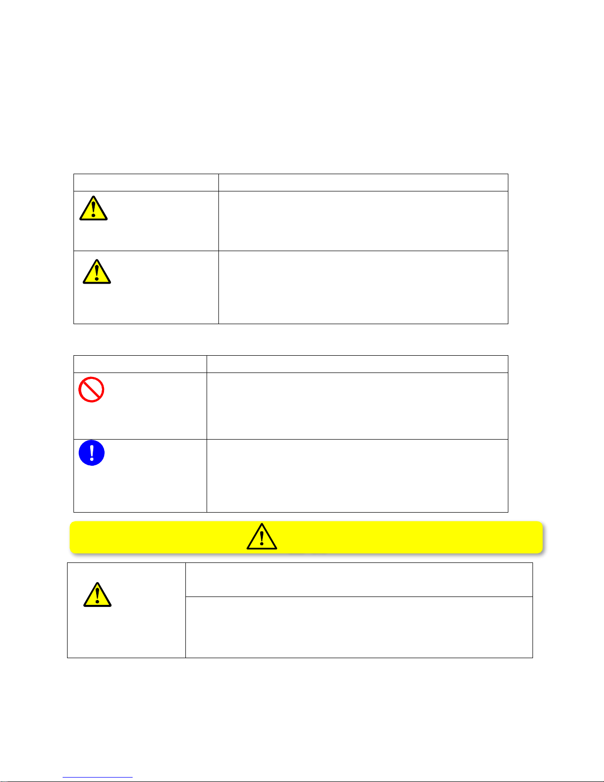
[Explanation of Indications Used in This Manual]
Indications
Meaning
WARNING
This indicates that mishandling of the product by the user
may result in death or serious injury.
CAUTION
This indicates that mishandling of the product by the user
may result in injury or damage to property.
[Explanation of Graphic Symbols Used in This Manual]
Graphic Symbol
Meaning
PROHIBITED
This indicates a "prohibited action" that must not be performed.
INSTRUCTION
This indicates an "instruction" that must be performed.
WARNING
1. Never allow pets or other living creatures inside the equipment. The
equipment and printing will not function properly.
2. During printing, be sure to keep the front cover closed, and do not put
your hands inside the equipment.
Otherwise, your hands may get caught by rotating parts and get injured
or burned by hot parts.
WARNING
Page 5
5
CAUTION
3. If the previous printed model or other obstacles are on the heat table, the
equipment and printing will not function properly. This is also may result in
equipment malfunction.
4. Safety cannot be assured when molded objects are used as houseware.
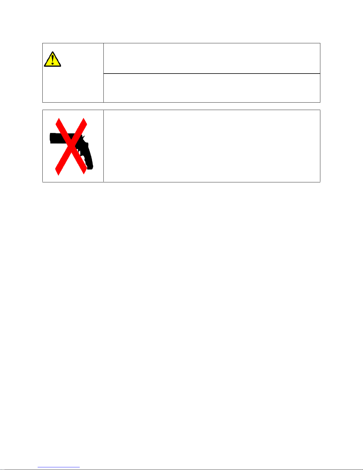
5. Never use MUTOH ENGINEERING INC. products for making objects that
violate the Ordnance Manufacturing Act, Swords and Firearms Control
Law (known more by its official name the Law to Control the Possession
of Firearms and Swords), regulations for the upbringing of young people
and other laws and ordinances, and public order and standards of decency.
MUTOH ENGINEERING INC. accepts no liability whatsoever for items
produced as indicated above and for their use.
Page 6
6
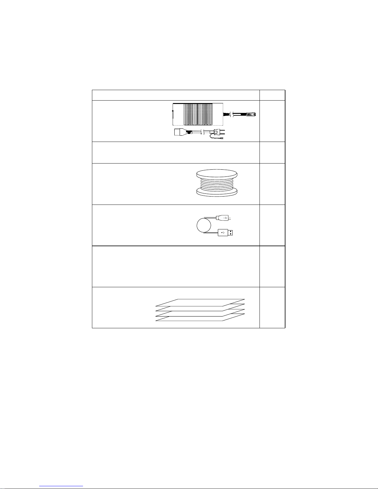
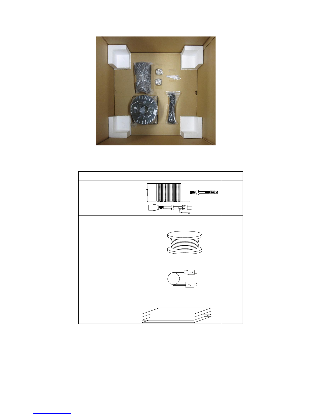
2. Checking Accessories
The following are the accessories for this equipment. Check that all accessories are provided in the
packing case.
Q'ty
1 pc
1 pc
1 pc
4 sheets
Accessory/Name
AC adapter for main
1 pc
AC adapter for LED lighting
(See "14. Using the MagiX LED Light.")
PLA filament (white) 1 kg
USB cable, 1.5 m
1 pc
Spanner (13 mm)
Polyimide tape
*This is attached to the table.
Page 7
7
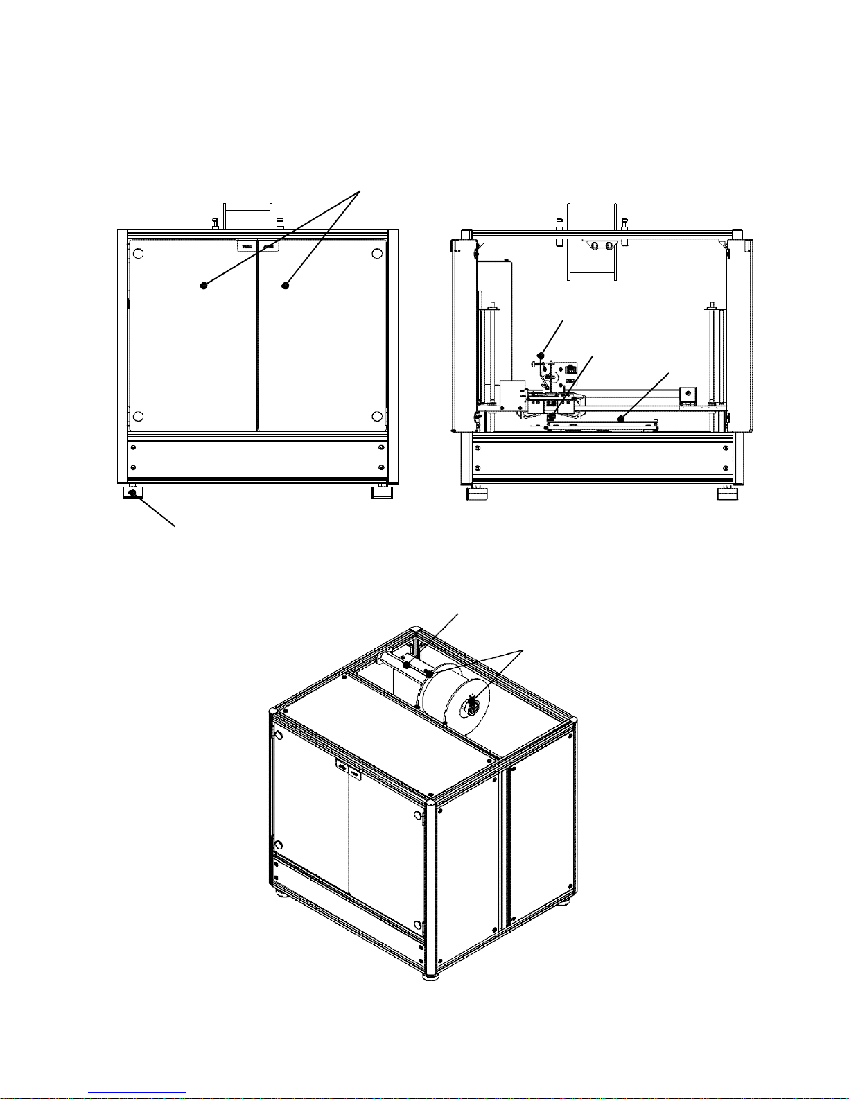
3. Names of Parts
Front Inside
Front side
Adjuster foot (4 locations)
Top
Filament shaft
Filament stopper
Filament guide
Print head
Heat
table
Page 8

8
Left side panel
Micro SD card slot
USB terminal
Power terminal
Page 9
9
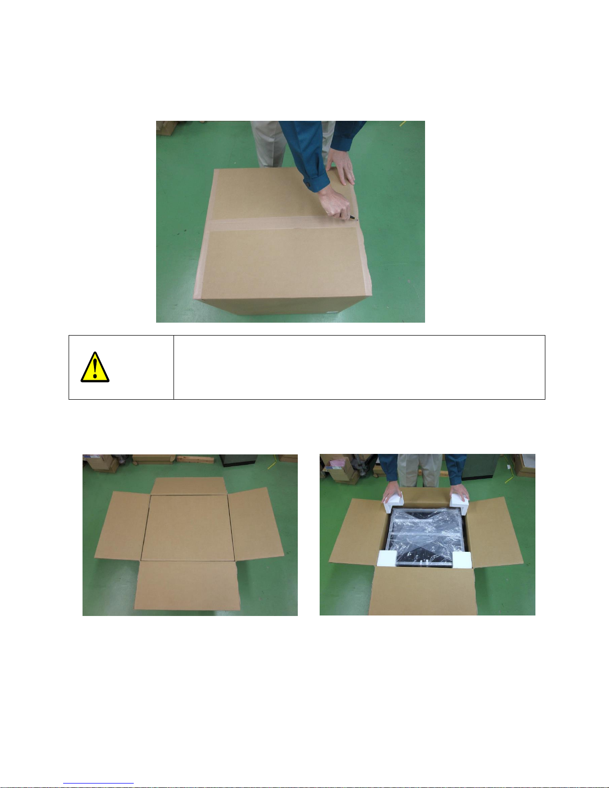
4. Installing the Main Unit
1. Open the top of the cardboard packing case.
2. Remove the pad from the top and the corner pads on all four corners.
CAUTION
・ When using a box cutter to open the cardboard packing case, take care not to
insert the blade of the box cutter too deep.
・
Doing so,it might damage the main unit.
Page 10
10
Top side view
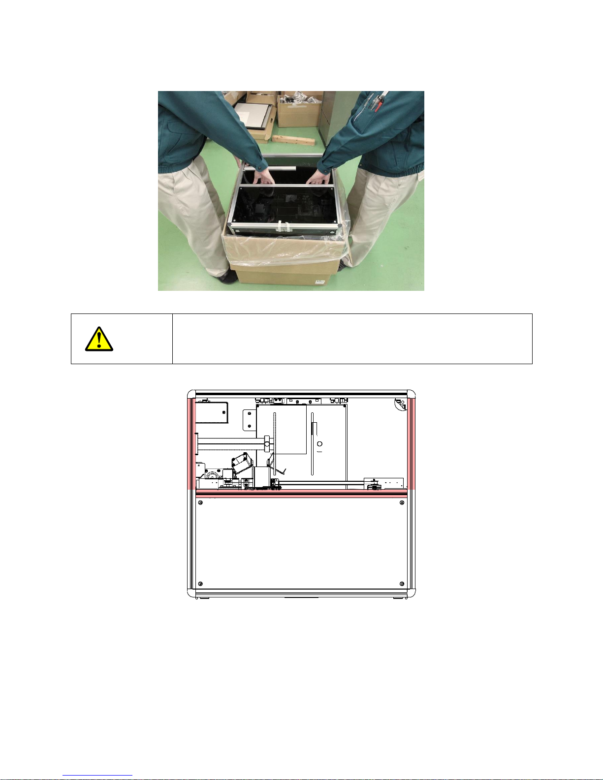
3. Remove the main unit.
Filament
4. Take out the accessories. The accessories are secured in place by tape
under the main unit.
CAUTION
・ This work should be performed by at least two personnel.
・
When removing the main unit, hold the frame at the sections marked in
red.
Page 11
11
The following are the accessories for this equipment. Check that all accessories are provided in the
packing case.
5. Install at a sturdy, level and stable location.
Q'ty
1 pc
1 pc
1 pc
4 sheets
Accessory/Name
AC adapter
1 pc
AC adapter for LED lighting
PLA filament (white) 1 kg
USB cable, 1.5 m
1 pc
Spanner (13 mm)
Polyimide tape
*This is attached to the table.
Page 12

12
WARNING
・
Install the main unit so that the power plug can be easily removed.
(A power switch is not provided on the main unit. So, remove the power plug when the
main unit is not to be used for a long time.)
・ Install the main unit at a level and stable location where it will not tip over or fall in the
event of an earthquake, for example.
Page 13

13
At the installation site, ensure at least 30 mm of space away from inflammable materials in the
surrounding area.
6. Adjust the adjuster feet.
■Prepare the 13 mm spanner (supplied).
(1) Adjust the adjuster feet so that all four feet are in contact with the surface of the installation
site.
(2) Turn the top ring to adjust the height of the adjuster feet.
(3) To lower the feet, turn left of the top ring. To left the feet, turn right of the ring.
*In the initial state, the feet are raised.
(4) When all four feet are in contact with the surface of the installation site, tighten the nut of the
adjusted feet with the spanner to secure the feet in place.
Tighten with the
spanner to
secure feet in
place
Falls Rises
Turn
30
30
30
View from top of main unit
Page 14
14
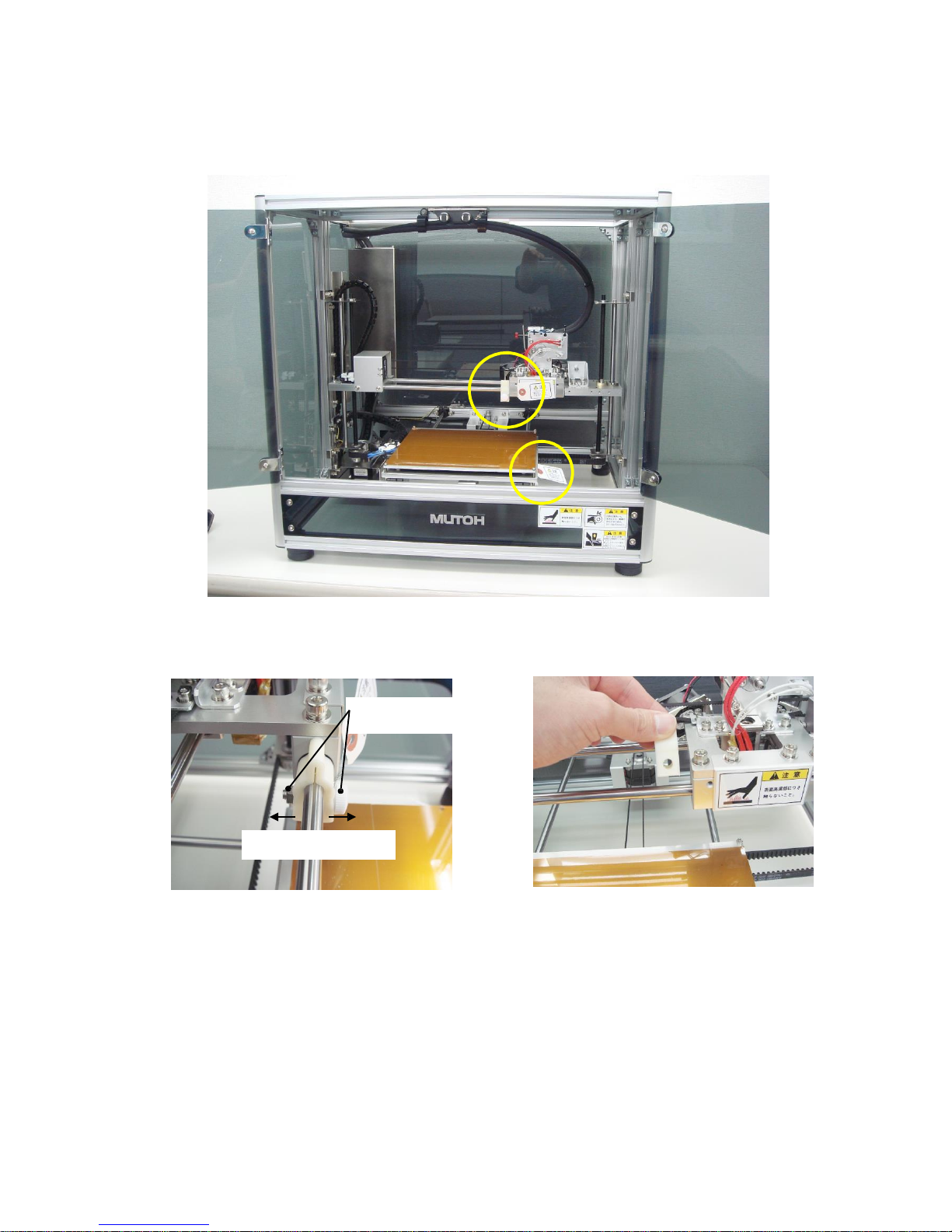
7. Remove the fixing brackets for the packaging.
■Two fixed brackets for the packaging are secured in place, one to secure the print head and one to
secure the heat table.
(1) Press the in packed bracket on the front face marked "PUSH" to open the door.
(2) Turn the nut and screw of the fixing bracket installed on the left side of the print head to
unfasten the bracket, and remove the bracket while opening it out.
(3) A fixing bracket is attached to the heat table on the front right side. In the same way as for
the print head, turn the nut and screw of the fixing bracket to loosen the bracket, and
remove the bracket while opening it out.
Turn the nut and screw to
remove
Remove while
Page 15
15
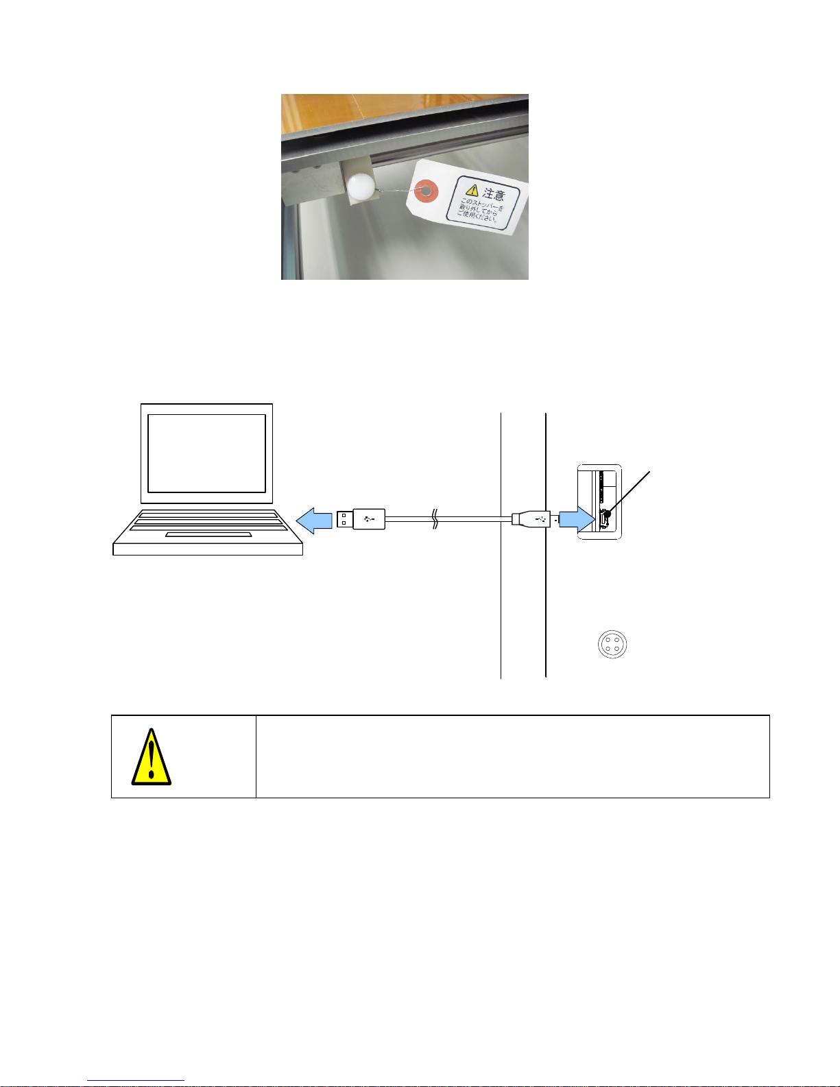
8. Connect the USB cable to the PC.
■Prepare the supplied USB cable
(1) Insert one end of the USB cable into the USB terminal on the left side panel of the main unit.
(2) Insert the other end of the USB cable into the USB terminal on the PC.
USB terminal
CAUTION
・ Allow sufficient slack in the cable. If the cable is taut, vibration may cause
the connection to become loose, which will result in communications being
disconnected and printing interrupted.
Page 16
16
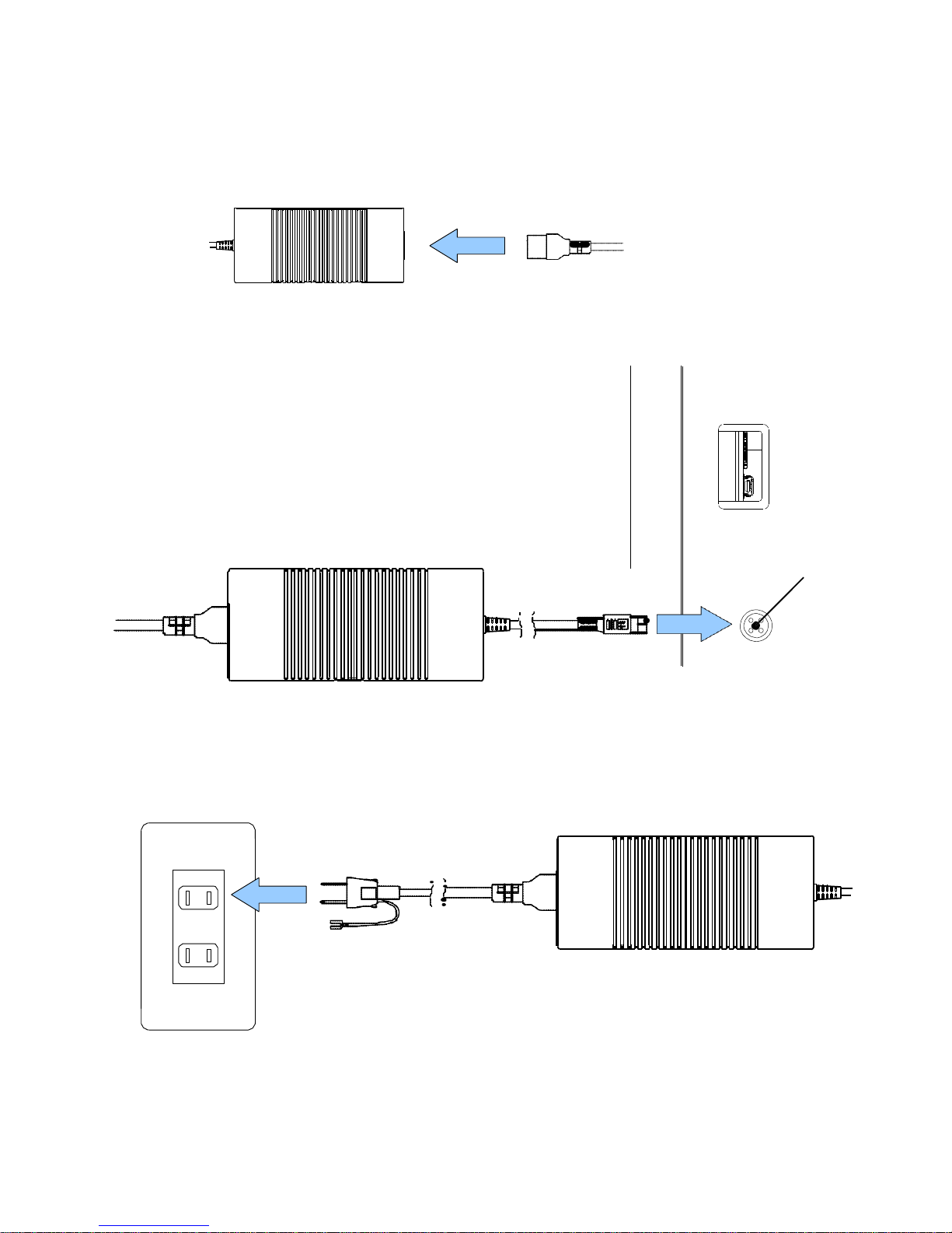
9. Connect the power cable.
■Prepare the AC adapter (supplied).
(1) Insert the cable (supplied) into the AC adapter main unit.
(2) Insert the round plug of the AC adapter into the power terminal on the side of the main unit.
Power terminal
(3) Insert the plug of the AC adapter into the power outlet.
Firmly insert the power plug into the 100 VAC power outlet properly.
We recommend to use ground for the usage of plug.
Page 17

17
5. Installing the Software
■Before installing the software, it must first be downloaded from our company's web site. Make sure
that PC environment of the PC to connect to the printer supports an Internet connection. If an Internet
connection is not supported, contact our Call Center and ask them to send you a CD containing the
software.
Use an English name comprising single-byte letter and number characters for the Windows user
accounts to be used. Operation may malfunction if user accounts contain a Japanese name (double-byte
characters).
The software comprises two pieces of software, the equipment control software Pronterface and the
model slicer Slic3r.
The following describes the procedure from software download through to installation.
(1) Access our company's MF Series web site.
http://www.mutoheng.com/3d
(2) Download the software from the MF Series web page.
(3) The software is downloaded as a zipped file. Double click this zipped file to unzip it at the desired
directory. (*Japanese is not allowed in the file path.) When the file is unzipped, you should see four
folders created.
* At our web site, the software is checked for viruses. A security warning may be displayed depending on
your PC environment. If a security warning is displayed, use your own anti-virus software to check for any
problems.
Page 18

18
(4) Create Desktop shortcuts for the control software and slicer startup files. After the file is
unzipped, the startup files are "Control software startup.bat" in the Pronterface folder and
"Slic3r.exe" in the Slic3r folder.
Creating a shortcut on
the Desktop
Creating a shortcut on
the Desktop
(5) Create shortcuts for the above files on the Desktop.
(Right click the file, and select "Send" > "Desktop (Create Shortcut).) This
completes installation.
Next, make the initial setup for the slicer.
Page 19

19
6. Initial Setup of the Slicer
■Initial setup of the slicer (Slic3r) (when started for the first time)
Before starting up Slic3r, start up the batch file and make the initial setup for the MF-1100.
(1) To start the initial setup, double click the "Slic3r setup installation.bat" file in the "Slic3r setup
file" folder.
The batch file is started up, and the initial setup is executed.
(2) Start up the slicer, and try checking if the initial setup has been made. To start up the slicer,
double click the "Slic3r.exe" shortcut on the Desktop. The initial setup has been completed if the
following screen is displayed.
Page 20

20
7. Installing the Driver on the PC Connected to the Printer
(first time only)
Download the driver from a PC environment that supports an Internet connection, and then install the
driver.
(1) To access the driver, access the web site of the following manufacturer.
Name of manufacturer: Corporate Headquarters Future Technology Devices International Limited
URL:http://www.ftdichip.com/
(2) In the menu on the left side of the screen, select "Drivers" > "VCP Drivers".
(3) Select the driver setup execution image (setup executable) for Windows from the table (Release
Date 2014-09-29) roughly in the center of the page.
Page 21

21
(4) Download the driver to a specified directory or place on the PC such as the Desktop, and execute
the file.
(5) Perform installation by following the on-screen messages.
Sample: Start up Windows 7 driver installation file "
CDM v2.12.00 WHQL Certified.exe
".
* To start up the file, right click on the file and then click
"Run as administrator".
[Reference 1] The COM number can be checked. (Windows 7 OS)
(1) Right click and select "Computer" in Windows, and select "Management".
(2) Select the "Device Manager" category from "Computer Management".
(3) The COM number can be checked by selecting "Port" from Device Manager and displaying
the tree.
Page 22

22
Page 23

23
8. Initial Setup of the Control Software
■Initial setup of the control software
(Pronterface)
(1) Set the port (Port). (required item)
Make sure that 3DMagiX is turned ON.
Next, start up Pronterface. (To start up,
double click the "Start Control Software"
icon.)
Next, select the COM number
you first checked from the "Port"
selection options.
(circled in red on the left)
If the COM ports are not displayed, restart
Pronterface.
(2) Set the communication speed to 250000 if it is not set.
(3) Click the "Connect" button to connect to the printer. When you have set and checked the port and
communication speed, click the "Connect" button. If the screen remains grayed out even by
pressing the "Connect" button, this means that the connection to the COM port has not been
made. Change the COM port value, and click the "Connect" button. When the connection is
made, the screen changes from the grayed out state to enter the online mode, and "Printer
online" is displayed on the console screen on the right.
Return to Z-axis home
(4) After the connection is made, click on the circular sections of [+X][-X][+Y][-Y]. This moves the
table and head. (Clicking closer to the outside of the circle increases the travel distance of the
table and head.) Move the head to near the center of the table.
(5) Next, click the "Z Height Home Return" button (see figure above). The head moves to the lowest
position.
Page 24

24
(6) Try inserting sheets of copy paper in between the table and the head. There is no problem in the
gap between the table and head if you feel slight resistance with two sheets inserted
(about 0.2 mm).
(Normally, the distance is adjusted before shipment from the factory.) If there is no longer any
resistance with three or more sheets inserted or only one sheet can be inserted, the Z-axis needs
to be adjusted. To adjust the Z-axis, you need a 2.5 mm hexagonal wrench. First, loosen the
lower fixing nut (5.5 mm), then turn the Z-axis adjusting screw to move the Z-axis up and down.
Adjust the Z-axis to the correct height. When adjustment is finished, tighten the fixing nut and
check the distance between the table and head again.
(7) Click the [+Z] direction button to raise the head about 5 cm from the table.
(8) Next, prepare the filament.
CAUTION
・ In low air temperatures, for example, the belt may harden and prevent the Z-
axis from moving. If this happens, turn the power OFF, try moving the belt by
hand to the left and right. When there is no longer any resistance, turn the
power back ON again, and try moving the belt again.
Head falls
Head rises
Head
Molding table
2 sheets of copy
Z-axis
Fixing nut
CAUTION
・ The Z-axis adjusting screw is for adjusting the sensor position of the Z home
position. The result of turning the screw is not immediately apparent. Move the
Z-axis about 10 mm in the [+Z] direction in Pronterface, and then click the "Z
Height Home Return" button. That height becomes the adjusted height.
Page 25

25
9. Preparing the Filament
■Prepare the genuine product (accessory) or separately purchased genuine product filament.
(1) Insert the filament reel into the filament shaft, and install the filament stopper. When the filament
stopper is installed, turn and secure the knob in place. At this time, make sure that the end of the
filament is at the front side facing down.
CAUTION
・ Output using a non-genuine filament cannot be assured.
・
Ensure a gap between the filament reel and filament stopper so that the filament
reel rotates smoothly. Insufficient rotation of the filament reel may prevent the
filament from being fed during printing.
・
After inserting the filament stopper, firmly secure the stopper in place by the
knob. If the filament stopper is loose, it might fall during operation.
・
Before inserting the filament, pull and extend the filament straight to a certain extent
to take up any kinks in the winding. We also recommend cutting the tip of the
filament at an angle so that it can enter the nozzle more easily.
・
The melting temperature of different types of filament varies. So, we recommend
changing the heater head when using different types of filament. Please note that
guarantees cannot be made when outputting different types of filament by a single
heater head.
・
PLA gradually becomes brittle and easily breaks due to hydrolysis caused by
humidity. After use, remove the reel from the main unit, and store it in a sealed
state. Be sure to use up the reel within three months. In particular, pay attention
when using or storing the reel in humid seasons.
CAUTION
・ Bring the filament into contact with the
pressurizing roller and feed gear. If these parts
are not in contact with each other, the filament
may no longer be fed during printing
Pressurizing arm
(2) Loosen the pressurizing arm knob, extend the arm, and
insert the filament end into the nozzle.
Insert the filament until its end is in contact inside the nozzle
by about 2 cm from the nozzle inlet. If it is difficult to
perform this operation, use long-nose pliers or another
tool.
(3) Tighten the pressurizing arm knob so that the spring is
about 5 to 6 mm long, and bring the filament into
contact with the pressurizing roller and feed gear.
Nozzl
Page 26

24
(4) In Pronterface, enter the temperature at the "Nozzle" item, and click the "Set" button. For PLA, enter
185℃, and for ABS, enter 230℃.
(5) Wait until the nozzle temperature has reached the specified temperature.
(6) When the nozzle temperature has risen to the specified temperature, enter "5 mm, @100 mm / min" in
the entry field under the "Feed Filament" button.
(7) Click the "Feed Filament" button, and check that the melted filament resin is pressed out from the
nozzle tip.
Click the "Feed Filament" button several times until resin is pressed out of the nozzle tip.
Before clicking the button again, wait for the feed unit to stop operating.
(8) When you have checked that resin is pressed out of the nozzle tip, remove the resin with tweezers
or a similar tool.
■How to remove the filament
The procedure for removing attached filament during replacement, for example, is as follows.
(1) Heat up the nozzle to a temperature matched to the filament that is currently attached. In Pronterface,
enter the temperature at the "Nozzle" item, and click the "Set" button. (For PLA, enter 185℃, and
for ABS, enter 230℃.)
(2) In Pronterface , click the "Draw Out" button. The end of the filament is drawn out of the nozzle.
(3) Remove the filament stopper and the reel.
WARNING
・ When removing resin, be sure to use tweezers or pliers.
・
This is because the nozzle and resin are hot immediately after they are pressed out.
Do not use your bare hands. Doing so might cause burns.
CAUTION
・ If the end of the filament hardens while it is being
drawn out, try reinserting the filament, reheating the
nozzle and clicking the "Draw Out" button again.
・
Take care with the end of the drawn out filament so
that it immediately passes through the hole in the reel
and does not cross over other filaments in the reel. If
filament crosses over other filaments in the reel,
this may result in the filament getting caught in the
reel during molding.
Page 27

25
10. Basic Operations
The flow of operations from preparing the model through to completion of printing is as follows:
Create the STL data to be printed using commercially available 3D CAD or modeling software.
How to create basic G code data
■Prepare the STL data of the model to be printed
(1) Start up Slic3r.
Preparation of model STL data
Conversion of STL data to G code data by slicer software
Slic3r
Printing of G code data by control software
Pronterface
Page 28

26
(2) On the "Filament Setting" tab, select the filament to be used. (The default setting is 3.0 mm PLA.)
Also, make sure that "Print Settings" or "Printer Settings" is set to "MF-1100".
(3) Either drag the STL file from Explorer, or click the "Add Model" button in the "Model Layout" tab
window to read the STL file to be printed.
(4) The external profile of the model is displayed. The 3D shape of the model can be checked by double
clicking the external profile.
(5) Change the settings as required. For example, to change the thickness of a layer (modeling pitch),
set the value of "Layer Thickness" at the "Layer and Wall" category in the "Print Settings" tab
window. Also, set support material related settings at the "Support" category.
* Supports are sometimes made quite strong in this version of the slicer software. So, if necessary, try
making them using version 0.9. For methods of use, refer to the MF-1000 Operation Manual.
ABS 1.75 mm
PLA 1.75 mm
ABS 3.0 mm
PLA 3.0 mm
Page 29

27
The minimum value is 0.05 mm and the maximum value is 0.5 mm. (In this example, this is set as
0.3 mm.)
(6) In the "Filament Settings" tab window, you can check the filament diameter and other settings. At
the slicer default setting, the "Slic3r setup installation.bat" file is started up and the settings
required at execution of that file are set in advance. You can also make "Cooling" related settings
regarding how the fan should be used.
For ABS, set a weaker fan value.
Reference
・ The print finish changes according to the modeling pitch setting.
・
Setting a small pitch setting results in a finer finish on the printed surface,
however, printing takes longer.
・
Setting a large pitch setting shortens the printing time but results in a
rougher printed surface.
Page 30

28
1
A modeling pitch of 0.05 mm is not guaranteed in all printing operations.
Page 31

29
(7) In the "Printer Settings" tab window, the size of the table (modeling plate), etc. can be checked.
Item
Check
Table size
X: 200 Y: 200
Print center
X: 100 Y: 100
Types of firmware G code
MF-1000, etc.
(8) Return to the "Model Layout" tab window, and click the "Output G Code" button.
(9) The Save G Code File window is displayed. Specify the directory to save the G code file to, and
click the "Save" button.
Page 32

30
(10) The G code file is created, and the amount of consumed filament is displayed.
(11) This completes creation of G code data. Exit Slic3r.
Select "File(F)" and click "Exit".
Next, perform printing using the G code file you created.
(12) Check the following items:
ž Power is supplied to the equipment from the AC adapter.
ž The PC is connected to the equipment by the USB cable.
(13) Start up Pronterface. Click the [Connect] button to connect to the printer.
Page 33

31
(14) Click the "Open" button, and read the G code file that you created.
The window for reading the G code file is displayed. Specify the G code file (.gcode) that you created
and click the "Open" button.
When reading of the G code file is completed, the print pass route is displayed in the grid in the
center. Also, the following details are displayed in the fields on the right side:
ž G code storage directory and file name
ž Total number of lines of G code
ž Print width, depth and height
ž Total number of layers and estimated required print time
Page 34

32
(15) Open the door before printing, and make sure that there are no objects
on the heat table. Also, wipe the table top clean.
(We recommend cleaning the table top with alcohol.)
Oil on your hands, for example, transferring to the heat table
might cause molded objects to dislodge from the table.
Be sure to close the door after checking inside the equipment.
(16) Click the "Print" button to start printing.
The print start time is displayed in the fields on the right side.
"Printing started at **:**:**" is displayed. (Hours, minutes and seconds are displayed at *.)
CAUTION
・ If the previous printed model or other obstacles are on the heat table, the
equipment and printing will not function properly. This also may result
in equipment malfunction.
WARNING
・ Before starting printing, be sure to close the door. If the door is open,
there is the danger that your hands might get inside while the equipment
is operating. There is also the risk that the nozzle temperature will not be
stable which might impair the finish of the printed model.
CAUTION
・ If the PC is in power save mode and enters sleep mode after a preset time
elapses, cancel that setting. Output stops when the PC enters a sleep
mode.
Clean with alcohol
Page 35

33
(17) When printing ends, the message "Printing ended at **:**:**. Time required for printing was
**:**:**" is displayed in the field at the bottom right, operation of the equipment head stops, and the
heat table moves to the front and comes to a stop.
(18) Cool the printed model to allow it to harden. After printing ends, the printed model is hot and
soft. Allow 10 to 15 minutes for the model to cool naturally since it is still attached to the table. The
printed model can be easily removed from the table once the table has cooled down. If you find it
difficult to remove the printed model from the table, you can also remove it by applying impact in
the side direction, for example, by lightly tapping with a plastic hammer.
CAUTION
・ Immediately after printing ends, the printed model is hot and soft.
Before removing the printed model from the table, allow it to cool down
naturally. Removing the printed model from the table while it is still hot
may result in the model being deformed or burns
.
Page 36

34
Detailed Description of Pronterface Software
(1) "Open" button
This reads G code files. G code files are appended with the .gcode extension. When a G code file
is opened, an image of the created model is displayed in the preview screen.
(2) "Print/Reprint" button
This prints G code files from the beginning after they have been read.
(3) "Pause/Resume" button
This pauses and resumes printing. When printing is resumed, the created model may deviate from
its intended position if the print head has been moved vertically or filament has been discharged
while printing is paused.
(4) "Off" button
This turns the motor, heaters and fans OFF.
*Be sure to disconnect the power plug when the equipment is not to be used for a long time.
(5) "Motor OFF" button
This turns the motor power OFF so that the equipment can be moved manually. The nozzle and heat
table are hot immediately after the motor is turned off. So, be careful of burns when moving the
equipment manually.
(6) XYZ motor operation panel
(When the equipment is installed with the front face facing the front, the X-, Y- and Z-axis
directions are as follows: the X-axis is the direction of left to right movement of the print head, the
Y-axis is the direction of front to back movement of the heat table, and the Z-axis is the direction
(1) (12)
(2
(3) (4)
(5
(6
(1(7(9(8(1
Page 37

35
of vertical movement of the print head.)
Page 38

36
Before starting manual operation, be sure to perform a home return.
The three axes return to their home positions by clicking the button at the bottom left of the circle.
To operate the motors, click any location within the circle. The axes move backwards, forwards, left
and right, in small increments when clicked near the center of the circle and in large increments when
clicked nearer the outside of the circle.
The bar (Z-axis) on the right side corresponds to operation of vertical print head movement. The
same applies here, too. The increment of movement increases the further away from the center you
click.
*Operations on this panel cannot be performed during creation of the model since instructions are
sent automatically from the G code file.
(7) Nozzle/heat table temperature operation panel
This panel is for operating the temperature of the nozzle and heat table. The temperature can be
adjusted by selecting or entering a desired temperature and then clicking "Set". Clicking "OFF" turns
the heater OFF.
(8) Nozzle/heat table temperature display panel
This panel displays the current and target temperatures of the nozzle and heat table in the form of a
line chart. The line chart is displayed on the temperature display panel when the "Monitor" option is
selected.
(9) Filament feed/return operation panel
This panel is for feeding and returning the filament. It is mainly used, for example, when replacing
the filament.
The filament is fed at the speed and length specified in the fields below by clicking the "Feed
Filament" and "Return Filament" buttons.
(10) Preview screen
This displays a trace of the G codes that have been read on the equipment. The trace is rotated by
dragging, resized by turning the mouse wheel, and point of view is changed by dragging to the right.
(11) Custom button panel
Users can set functions to the buttons on this panel. Buttons set by default are the "fan operation",
"draw out filament", "stop printing from SD card", and "display current nozzle position" buttons.
(12) SD card button
This transfers data and saves it to MicroSD card for the printer, or displays data saved on MicroSD
card as a list for printing. After printing is started, operation continues even if the USB cable is
disconnected.
Page 39

37
11.
Printing from MicroSD Cards
MicroSD cards containing G code files can be loaded on the MF-1100 main unit so that these files can
be printed. Printing is started on the PC. However, once printing is started on the MF-1100, the PC can
be turned OFF or the USB connection can be disconnected so that other operations can be performed.
(1) Save the G code file on the PC to the MicroSD card. At this time, be sure to use single-byte letter
and number characters for file names, and avoid using Japanese double-byte characters.
(2) Load the MicroSD card containing the G code file on the main unit.
*Take care not to drop the MicroSD card inside the printed
circuit boards.
*SD cards through to SDHC cards are supported.
SDXC cards cannot be used.
(3) Start up the control software Pronterface, and select [SD Card] > [Print from SD Card].
(4) The content of the SD card is displayed as a list. Long file
names are displayed using the first eight characters of the
name followed by three characters of the file extension as
shown on the right. Select the file to print, and click the
[OK] button. Printing is started.
After printing is started, the PC can be turned OFF or the USB cable can be
disconnected.
(5) To stop printing midway, start up the control software Pronterface, and
enter and send the M25 code in the Send Code field. Printing can be
resumed by entering and sending the M24 code.
CAUTION
・ Use of "Upload to SD Card" is not recommended since uploading is slow
and impractical.
Page 40

38
12. Reattaching Polyimide Tape
To ensure adhesion between an object and the table, attach polyimide tape to the top of the heat table
before using the equipment.
The adhesion between the polyimide tape and the molded object drops when the number of molds made
increases. We also recommend reattaching polyimide tape when there are apparent tears and areas
where the tape is rising up from the table.
Use only polyimide tape recommended by MUTOH ENGINEERING INC.
(1) (Only when the main unit is in operation) End communication with the PC, and disconnect the AC
adapter cable from the main unit.
Then, wait about 20 minutes for the head and heat table to return to room temperature.
(2) Peel off the used polyimide tape from the heat table.
(3) Lightly wipe the top of the heat table with OA cleaner for LCD displays or cleaner for TV screens,
for example.
(4) Attach new polyimide tape to the heat table. Evenly attach the polyimide tape to the table top.
WARNING
Before performing this step, be sure to stop the equipment and disconnect the
power cable from the main unit.
The equipment might operate when your hands are inside, which is dangerous.
Reference
・ The surface of the molded object can be molded to a clean finish if the
polyimide tape is attached without any air bubbles .
・
Remove any air bubbles formed between the polyimide tape and the table
top by either reattaching the tape or by pricking them with a needle or a
similar sharp object.
・
The surface of the molded object can be molded to a clean finish if the
gap between attached stripes of tape is kept to a minimum.
Page 41

39
Hexagon socket
Connec
13. Replacing the Heater Head
Filaments come in two diameters, 3.0 mm and 1.75 mm. When changing filaments, the heater head
must also be replaced to accommodate the new filament diameter. The melting temperature of the
filament also differs when you change the type of filament (PLA/ABS). So, we recommend using
heater heads selectively.
(1) Remove the filament from the main unit (for details
on how to remove filaments, see "9. Preparing the
Filament"), and disconnect the AC adapter cable
from the main unit.
Then, wait about 20 minutes for the head and heat table to
return to room temperature.
(2) Disconnect the two connectors. (Draw them out while
pressing the tabs. If the connector below is difficult
to remove, use a tool to press in the tabs.
*Photograph on right.)
(3) Remove the hexagon socket head cap bolts from the
metal panel securing the head in place with a 2.5 mm
hexagonal wrench.
(4) Remove the head from the depression, and attach the
head to be replaced in the same way.
(5) Install the metal panel, install the bolts to their original positions, and secure the head in place.
(6) Connect the two connectors.
(7) Turn the power ON, start up Pronterface, and click the "Connect"
button. If an error is displayed, initialize the main unit. Enter the
"M999" code in the Send Code field at the bottom right, and click the
[Send Code] button.
(8) After replacing the heater head, adjust the Z-axis height because it sometimes changes. Move the
head down to its lowermost position near the center by clicking the "Z Height Home Return"
button.
If previously used resin is still attached to the tip of the head, warm the head up to about 100℃
Page 42

40
and remove the resin. The Z-axis height cannot be adjusted properly with resin still attached to
the tip of the head.
Page 43

41
(9) Try inserting sheets of copy paper in between the table and the head. There is no problem in the gap
between the table and head if you feel slight resistance with two sheets inserted (about 0.2 mm).
(Normally, the distance is adjusted before shipment from the factory.) If there is no longer any
resistance with three or more sheets inserted or only one sheet can be inserted, the Z-axis needs to
be adjusted. To adjust the Z-axis, you need a 2.5 mm hexagonal wrench. First, loosen the lower
fixing nut (5.5 mm), then turn the Z-axis adjusting screw to move the Z-axis up and down. Adjust
the Z-axis to the correct height. When adjustment is finished, tighten the fixing nut and check the
distance between the table and head again.
(10) This completes replacement of the head and adjustment of the Z-axis.
Head falls
Head rises
Head
Molding table
2 sheets of copy
Z-axis
Fixing nut
CAUTION
・ The Z-axis adjusting screw is for adjusting the sensor position of the Z home
position. The result of turning the screw is not immediately apparent.
Move the Z-axis about 10 mm in the [+Z] direction in Pronterface, and then click
the "Z Height Home Return" button. That height becomes the adjusted height.
・ The melting temperature of different types of filament varies. So, we recommend
changing the heater head when using different types of filament. Please note that
guarantees cannot be made when outputting different types of filament by a
single heater head.
Page 44

42
14.
Using the MagiX LED Light
The MF-1100 has a built-in LED light as standard.
To turn the LED light ON, connect the AC adapter to the jack at the bottom on the left side.
Front
Position of
Insert into jack
To power
Page 45

43
(Supplementary Explanation 1) Glossary
・ Slicer software
This software determines which operations are to be used to print STL or other polygon data, and
saves the resulting data as a "G code file." It is called "slicer" because it calculates cross-sections
obtained by slicing the cross-section of a polygon one layer at a time to create contours. "Slic3r" is
the slicer software for MF-1100.
・ Control software
This software sends G codes to the printer one instruction at a time. "Pronterface" is the control
software for MF-1100.
・ G code
This is code programmed with all printer operations such as "heat nozzle to 185 degrees", "move
100 mm along X-axis" and "turn the fan when output reaches 50%". The printer receives this code
from the control software to operate as instructed. A "G code file" contains a single group of the G
codes.
This means that a G code file contains all elements such as modeling pitch, temperature conditions
and wall conditions.
・ STL file
STL stands for "STereoLithography," and is the most widely used polygon format for 3D printers.
・ Polygon
This data expresses the shape of a 3-dimensional object using multiple triangles. Although objects
comprising planes can be expressed by a few polygons, an extremely large number of polygons are
required to accurately express curved surfaces.
・ Home return
Immediately after the power is turned ON or after the equipment is moved manually, the printer
can no longer identify the position of the nozzle. If the nozzle is moved as it is, it will move to a
position outside the allowable operating range and may cause a malfunction. All of the three X-,
Y- and Z-axes (horizontal, depth and height) are provided with an "origin switch." The printer can
accurately identify the position of the nozzle by the motor being operated until this origin switch is
pressed. This operation is called "home return."
Page 46

44
(Supplementary Explanation 2) Troubleshooting
Symptom
Cause
Remedy
Power does not turn ON
*The MF-1100 does not have
a power switch.
The power connector is not inserted
into the power outlet.
Insert the connector into the power outlet.
The main cable for connecting unit to
the AC adapter is not connected to the
adapter main unit.
Insert the cable.
Printer cannot communicate
with the PC
The printer is not connected to the PC
by the USB cable.
Insert the cable.
The serial USB driver is not installed.
Install the driver.
The connection port on the control
software Pronterface is not specified
correctly.
Specify the COM port that was assigned when the
serial USB driver was installed.
A connection has not been
established by the control software
Pronterface.
Press the "Connect" button to establish a connection.
Communication is
discontinued during
printing
Communication was stopped by the
setting sleep mode.
Cancel the sleep mode.
Vibration loosened the USB cable.
Allow sufficient slack in the USB cable. Also, try
securing the USB cable by tape.
Printing does not work
The printer is not connected to the PC
by the USB cable.
Insert the cable.
Resin is not dispensed from the nozzle.
Reinsert the filament into the nozzle. (For details
on how to insert the nozzle, see "Preparing the
Filament" in this manual.)
A connection has not been
established by the control software
Pronterface.
Press the "Connect" button to establish a
connection.
If a connection is not made, check the COM
port number or the cable connection.
The G code file has not been read to the
control software Pronterface.
Read the G code file, and then click the "Print"
button.
The nozzle and print head are at a
lower temperature.
Set the correct temperature corresponding to the
filament from the nozzle/heat table temperature
operation panel in Pronterface.
Wait for the nozzle and heat table to reach the
temperature set in the G code data.
A warning is displayed
when data is read by the
slicer (Slic3r)
The STL data contains minute holes.
These can be repaired in the free software
MeshLab, for example.
Even if a warning is output, these holes are
sometimes repaired by the slicer and new G code
data.
The slicer (Slic3r) crashes
during G code conversion.
This is a file-based phenomenon.
Try using the slicer's expert mode.
The STL data is 15 M or larger in size.
Try reducing the number of polygons in the free
software such as MeshLab.
The base of the molded
object peels away, causing
the object to rise up from the
tape
Fine dirt particles or oil are
adhering to the heat table.
Lightly wipe the top of the heat table with OA
cleaner for LCD displays or cleaner for TV screens.
The molded object peels away
from the heat table due to
deformation caused by cooling
(ABS)
We recommend stopping the fan or using it at
a weaker setting.
(Use the slicer's expert mode.)
The molded object cannot be
molded to a clean finish
The gap between the nozzle and heat
table is inappropriate.
Adjust the Z-axis home position limit to correct
the gap.
Page 47

45
The Z-axis is not parallel.
Adjust the height of the heat table using the four
height adjusting screws so that the table is parallel.
The equipment runs out of
filament during printing.
Stop printing by the "Pause" button in Pronterface,
replace with a new reel of filament, and resume
printing.
Page 48

46
(Supplementary Explanation 3) Main Unit Specifications
Model
MF-1100
Molding method
Fused Deposition Modeling (FDM)
Number of heads
1 (produced in house)
Max. molding size (X x Y x Z)
200 x 200 x 170 mm
Z-axis resolution
Min. modeling pitch 0.1 mm to max. modeling pitch 0.5 mm
Materials used
ABS/PLA (dia. 3.0 mm/1.75 mm)
Supported OS
Windows 7, Windows 8, Windows 8.1
Recommended PC specifications
CPU: Pentium 4 or later, memory: 2 GB or more
Software
Control software: Pronterface (Japanese version)
Slicer software: Slic3r (Japanese version)
Input data format
STL
Data transfer
USB connection, MicroSD card (used for recording G code files)
Main unit weight
17 kg
External dimensions (L x W x H)
500 x 550 x 530mm
Input voltage
100 VAC 50/60 Hz
Power consumption
200 W
Page 49

47
Revision History
January 20, 2015
1st version
February 24, 2015
Warranty Provisions added. Warranty is voided if the product is resold.
March 5, 2015
Drawings for table cleaning added.
March 16, 2015
AC adapter for LED light also is provided as an accessory.
May 7, 2015
Use an English name comprising single-byte letter and number characters for the
May 13, 2015
Photographs were added to show how to remove head connectors.
Page 50

48
44
Page 51

49
Drafted by and copyright owned by MUTOH
ENGINEERING INC.
Reproduction of this document is strictly prohibited.
Value3D MagiX Customer Center
(TEL: 0120-147-610/Mail:info.3d@mutoheng.jp)
May, 2015
 Loading...