

Page 1
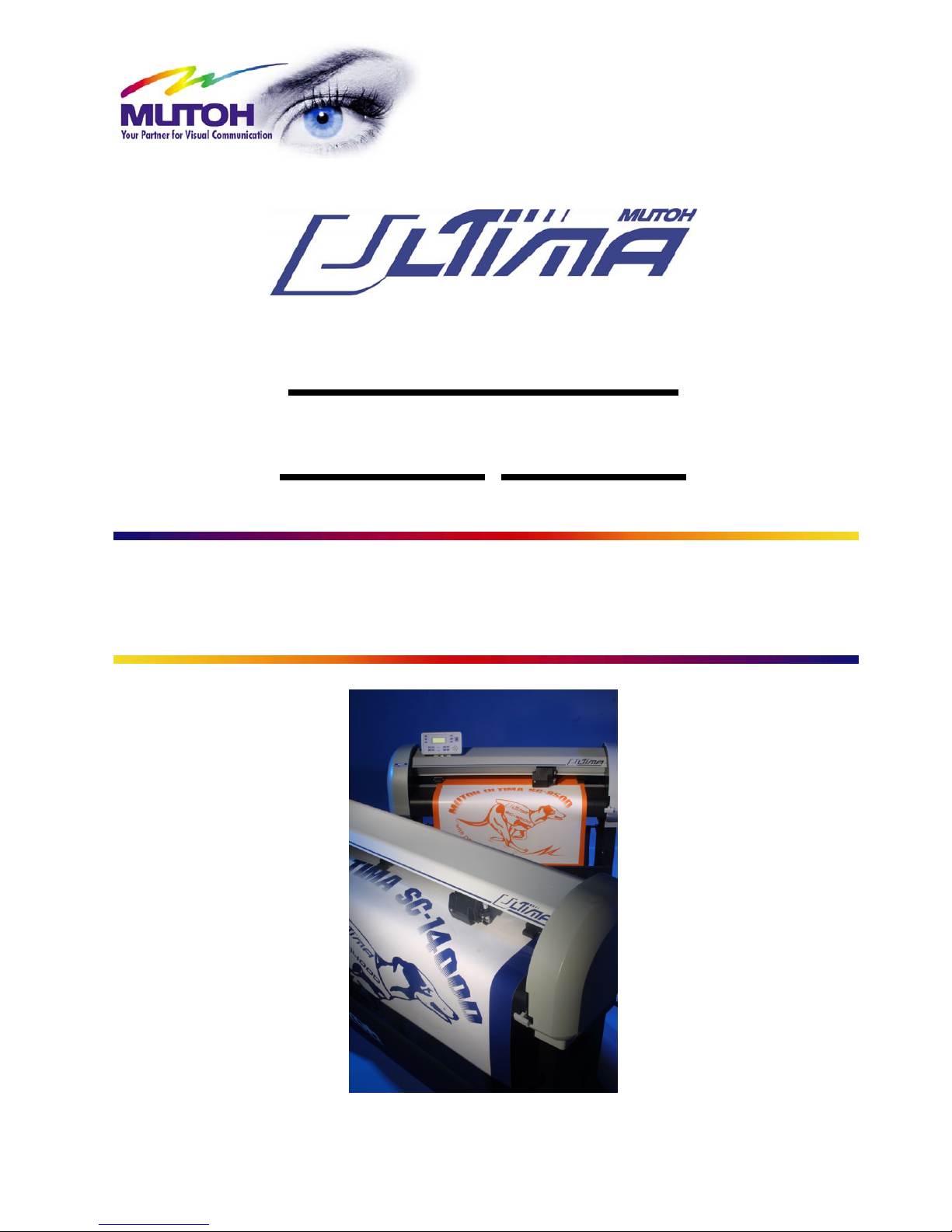
Multi-Purpose
Cutting
Plotter
Operation Instructions
MUTOH EUROPE N.V.
AP-75125, Rev 1.3, 20/10/2004
Page 2

2
AP-75125, Rev 1.3 ; 20/10/04
Page 3

Mutoh Ultima Multi-Purpose Cutting Plotter - Operation Instructions
3
AP-75125, Rev 1.3 ; 20/10/04
COPYRIGHT NOTICE
COPYRIGHT © 2004 Mutoh Europe N.V. All rights reserved.
This document may not be reproduced by any means, in whole or in part, without written permission of the
copyright owner.
This document is furnished to support the MUTOH Ultima cutting plotter. In consideration of the furnishing of
the information contained in this document, the party to whom it is given assumes its custody and control and
agrees to the following:
¾ The information herein contained is given in confidence, and any part thereof shall not be copied or
reproduced without written consent of Mutoh Europe N.V..
¾ This document or the contents herein shall under no circumstances be used in t he manufacture or
reproduction of the article shown and the delivery of this document shall not constitute any right or
license to do so.
October 2004
Published: Mutoh Europe N.V., Archimedesstraat 13, B-8400 Oostende, BELGIUM
Page 4

Mutoh Ultima Multi-Purpose Cutting Plotter - Operation Instructions
4
AP-75125, Rev 1.3 ; 20/10/04
Page 5

Mutoh Ultima Multi-Purpose Cutting Plotter - Operation Instructions
5
AP-75125, Rev 1.3 ; 20/10/04
Dear Customer,
Thank you for choosing a Mutoh Ultima series sign cutting plotter. The Mutoh Ultima drag knife cutting plotter
has been designed to be one of the most user-friendly and versatile cutting plotters in the market.
As a stand-alone cutting plotter, the Ultima can cut and plot designs onto paper as required.
In combination with an inkjet printer, the Ultima cutting plotter is ready for contour-cutting of pre-printed signs
made with any printer capable of printing onto cutting plotter compatible media. Contour-cutting is made
possible via the integrated EPOS (electronic positioning) technology and the in-the-box software.
But even more important, it is easy to use, as the following guide will show you.
Page 6

Mutoh Ultima Multi-Purpose Cutting Plotter - Operation Instructions
6
AP-75125, Rev 1.3 ; 20/10/04
Page 7

Mutoh Ultima Multi-Purpose Cutting Plotter - Operation Instructions
7
AP-75125, Rev 1.3 ; 20/10/04
Table Of Contents
1. REGULATORY AND SAFETY INFORMATION........................................................................................... 9
1.1. EMC STATEMENT FOR CE MARKING.......................................................................................................... 9
1.2. FCC COMPLIANCE .................................................................................................................................... 9
1.3. IMPORTANT NOTE...................................................................................................................................... 9
1.4. SAFETY LABELS: SAFETY LABELS, SYMBOLES DE SECURITE, SICHERHEITSSYMBOLE................................. 10
2. INSTALLATION PROCEDURES................................................................................................................ 11
2.1. PREPARING THE CUTTING ENVIRONMENT.................................................................................................. 11
2.2. PARTS LIST............................................................................................................................................. 12
2.3. UNPACKING AND SETTING UP THE ULTIMA CUTTER ................................................................................... 13
2.4. CUTTER PARTS & COMPONENTS .............................................................................................................. 14
2.5. CONNECTING THE CUTTER TO THE COMPUTER.......................................................................................... 16
2.6. CONNECTING THE POWER CABLE ............................................................................................................. 17
2.7. INSTALLING A TOOL ................................................................................................................................. 18
2.8. LOADING MEDIA ...................................................................................................................................... 19
2.8.1. Loading cut sheet media............................................................................................................... 19
2.8.2. Loading roll media......................................................................................................................... 20
2.9. TEST SHEET VERIFY EPOS ALIGNMENT...................................................................................................... 22
2.9.1 EPOS Alignment → test plot.......................................................................................................... 22
3. CUTTER CONTROLS................................................................................................................................. 23
3.1. UNDERSTANDING THE OPERATION PANEL................................................................................................. 23
3.2. DIRECT KEY ACCESS ............................................................................................................................... 27
3.2.1. Force selection.............................................................................................................................. 27
3.2.2. Speed selection ............................................................................................................................ 28
3.2.3. Offset selection ............................................................................................................................. 28
3.2.4. Tool selection................................................................................................................................ 29
3.2.5. Origin selection ............................................................................................................................. 29
3.2.6. Test selection................................................................................................................................ 30
3.2.7. Presets selection........................................................................................................................... 30
3.3. CONTOUR CUTTING ................................................................................................................................34
3.4. SQUARE DETAILS .................................................................................................................................... 37
4. CUTTER SETTINGS & SPECIAL FUNCTIONS......................................................................................... 39
4.1. GENERAL PROCEDURE TO CHANGE SETTINGS ON THE CUTTER .................................................................. 39
4.2. OVERVIEW OF GENERAL SETTINGS .......................................................................................................... 39
4.3. LANGUAGE SELECTION............................................................................................................................ 40
4.4. KEY COMBINATIONS ................................................................................................................................41
5. FINETUNING YOUR CUTTER TO OBTAIN MUTOH QUALITY................................................................ 43
5.1. ADJUSTING THE KNIFE DEPTH .................................................................................................................. 43
5.2. OFFSET PRINCIPLE.................................................................................................................................. 45
5.3. OFFSET EFFECT...................................................................................................................................... 45
5.4. OFFSET ADJUSTMENT PROCEDURE .......................................................................................................... 46
5.5. PERFORMING A TEST CUT........................................................................................................................ 48
5.6. TROUBLESHOOTING ................................................................................................................................49
6. ULTIMA CUTTING PLOTTERS - MEDIA COMPATIBILITY & DIMENSIONS......................................... 51
6.1. ULTIMA CUTTING PLOTTERS: MEDIA COMPATIBILITY .................................................................................. 51
6.2. PHYSICAL DIMENSIONS ULTIMA................................................................................................................ 51
Page 8

Mutoh Ultima Multi-Purpose Cutting Plotter - Operation Instructions
8
AP-75125, Rev 1.3 ; 20/10/04
Page 9
Mutoh Ultima Multi-Purpose Cutting Plotter - Operation Instructions
9
AP-75125, Rev 1.3 ; 20/10/04
1. REGULATORY AND SAFETY
INFORMATION
1.1. EMC STATEMENT FOR CE MARKING
Important :
This is a Class A product approved for industrial environments. In a domestic
environment this product may cause radio interference in which case you may be
required to take adequate measures.
1.2. FCC COMPLIANCE
This equipment complies with the requirements for a Class A computing device in the FCC rules, part 15,
subpart J.
Operation of this device in a residential area may interfere with television reception or operation of utilities.
Cutters generate weak radio signals and may interfere with television reception and utilities. If the cutter
does interfere with radio or TV reception, try the following:
¾ Change the direction of your radio and TV reception antenna or feeder.
¾ Change the direction of the cutter.
¾ Move either the cutter or the receiving antenna so that there is more distance between them.
¾ Be sure the cutter and the receiving antenna are on separate power lines.
1.3. IMPORTANT NOTE
Technical problems and maintenance, which require the cutter to be opened, can only be done by qualified
personnel who were trained to repair this type of machine.
Unauthorized removing of covers and/or overruling safety locks can be dangerous and will result in your
guarantee becoming void.
Page 10
Mutoh Ultima Multi-Purpose Cutting Plotter - Operation Instructions
10
AP-75125, Rev 1.3 ; 20/10/04
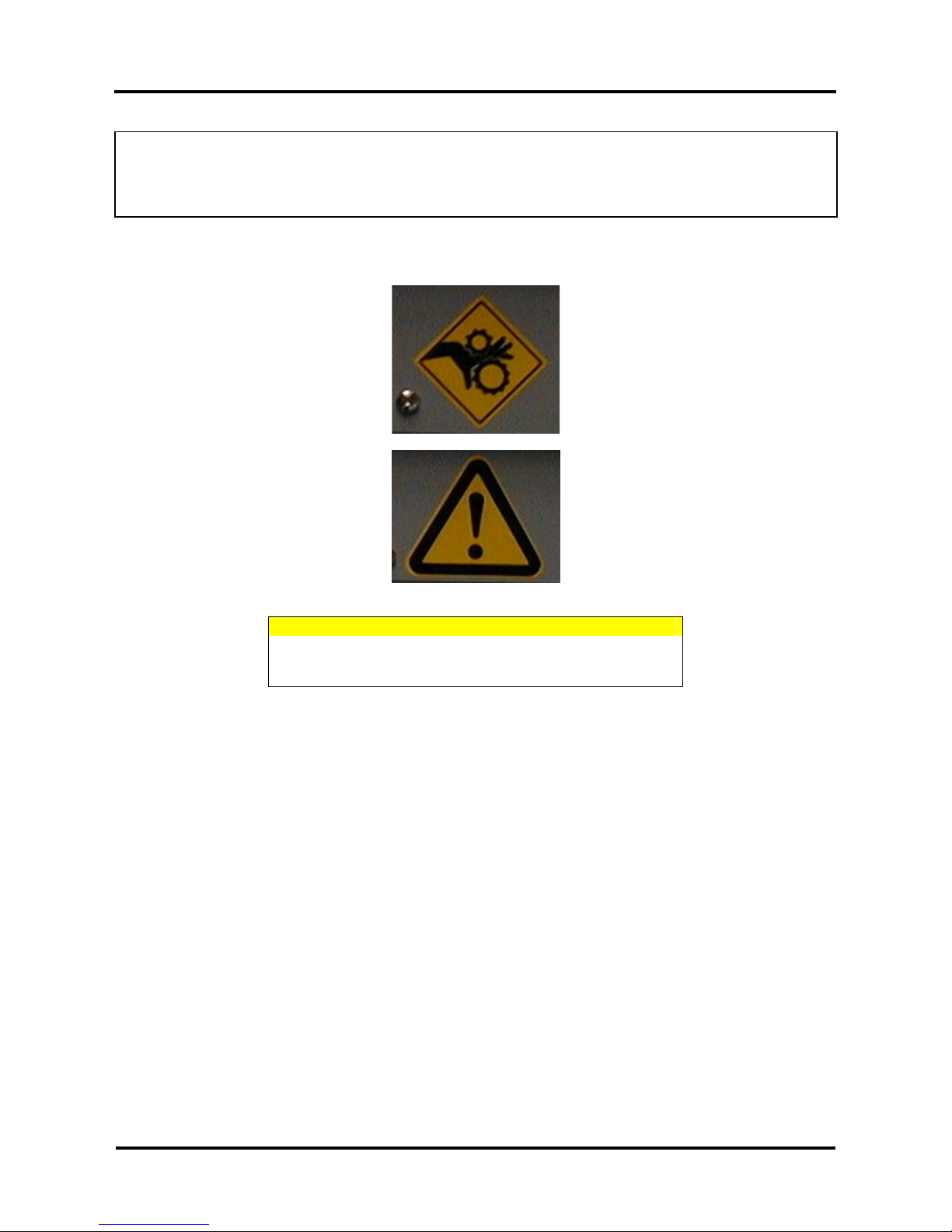
1.4. SAFETY LABELS:
SAFETY LABELS, SYMBOLES DE SECURITE,
SICHERHEITSSYMBOLE
Safety Labels are attached to the internal and external area of the cutter to alert you to potentially hazardous
situations or conditions. The following safety labels are used in and on the cutter:
CAUTION
When tilling or storing the media scroller, always keep the
fixed flange side at the bottom to avoid media from sliding
down.
Page 11
Mutoh Ultima Multi-Purpose Cutting Plotter - Operation Instructions
11
AP-75125, Rev 1.3 ; 20/10/04
2. INSTALLATION PROCEDURES
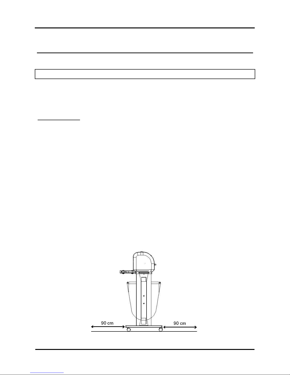
2.1. PREPARING THE CUTTING ENVIRONMENT
The location where you set up your equipment is very important. Please see to it that it meets following
conditions :
Power supply of 100 to 120 VAC 50/60 Hz or 200 to 240 VAC 50/60 Hz.
Ambient Conditions
:
Operating environment
- Temperature : 5 °C to 30 °C
- Humidity : 35 % - 75 % non-condensing.
Recommended environment
- Temperature : Room temperature 16 °C to 25 °C
- Humidity : 50 % to 65 %, non-condensing.
Variation rate
- Temperature : 2 °C per hour.
- Humidity : 5 % per hour.
Storage environment
- Temperature : 0 °C to 50 °C
¾ Please protect your cutter from moisture, dust, draughts and direct sunlight. It is best to keep your
machine away from open windows and air-conditioners.
¾ See to it that there is an adequate space around the cutter so that ventilation is not obstructed.
¾ Avoid unnecessary vibrations and set up your cutter on a level surface.
¾ When selecting a place for your cutter, leave at least 90 cm in front and 90 cm at the rear, as shown in
the illustration below.
Page 12
Mutoh Ultima Multi-Purpose Cutting Plotter - Operation Instructions
12
AP-75125, Rev 1.3 ; 20/10/04
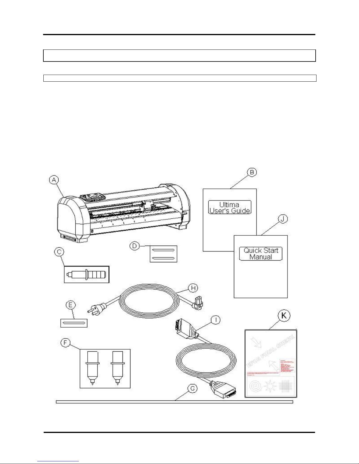
2.2. PARTS LIST
Contents of the plotter box :
A Plotter unit with roll support system, 2
conveyor rolls and small guiding flanges.
F Set of 2 water-based fiber tip pens.
B Mutoh Ultima User’s Guide. G Spare cutting mat (1 pc).
C One knife holder with pre-mounted cutting
blade
H Power Cord.
D Set of 2 spare cutting blades and 1 spring for
cutting jobs (45°/ Offset 0.50 mm).
I RS-232 or USB interface cable
E Blade for auto sheet-off. (1 pc – pre-installed
in tool head)
J Quick Start Manual (includes a CD-rom)
K Test sheet verify epos alignment (AP-77010)
Page 13
Mutoh Ultima Multi-Purpose Cutting Plotter - Operation Instructions
13
AP-75125, Rev 1.3 ; 20/10/04
2.3. UNPACKING AND SETTING UP THE ULTIMA CUTTER
Notes :
¾ When unpacking the cutter, check whether all parts described in the parts list are
included in the box. Consult your dealer if anything seems to be missing.
¾ Lifting the machine out of the box should be done by two persons. This to avoid
back injuries.
¾ Protect the plotter from firm shocks.
¾ Do not dismantle the unit
To unpack the cutter:
Step 1 : Open the box.
Step 2 : Remove the buffer box.
Step 3 : Remove the packaging set.
Step 4 : Take out the cutter box.
Step 5 : Lift the cutter unit out of the box and put it on a flat and stable surface.
Step 6 : Remove all plastic wrapping materials.
Step 7 : Remove the pieces of foam, protecting the tool head during transportation.
Step 8 : If you had your cutter deliv ered with a stand, please refer to the instructions for mounting the
stand.
Page 14

Mutoh Ultima Multi-Purpose Cutting Plotter - Operation Instructions
14
AP-75125, Rev 1.3 ; 20/10/04
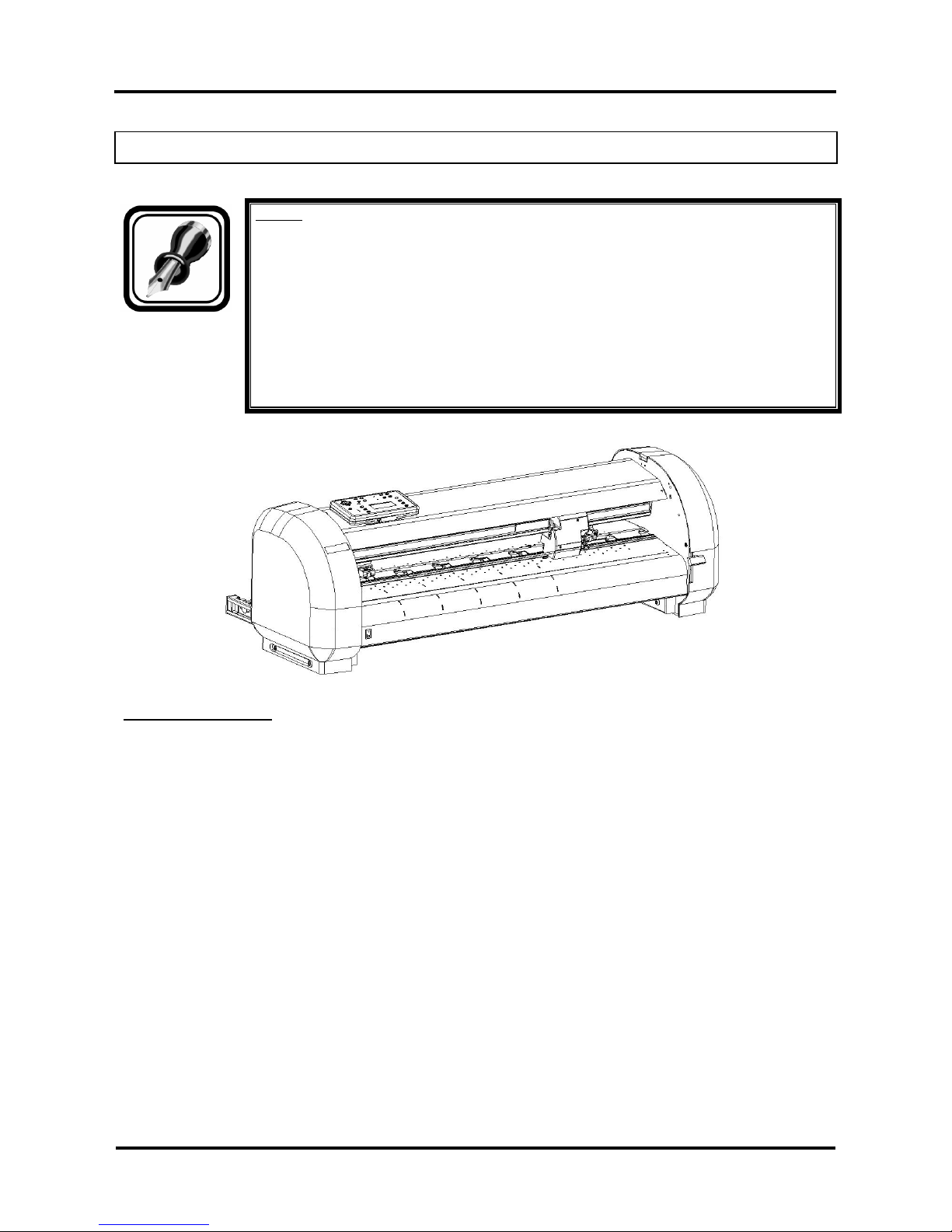
2.4. CUTTER PARTS & COMPONENTS
Part Description
1 Operation Panel
Removable Panel with LCD-display and control keys.
2 Power Switch
Switches the Ultima cutting plotter ON or OFF.
3 Roll Support System
The roll support system carries the conveyor rolls.
4 Conveyor Rolls
When using roll media for cutting jobs, put the roll of media on
top of the two conveyor rolls.
5 Small guiding Flanges
These flanges on the conveyor rolls will prevent the roll of media
from shifting to the left or to the right when vinyl is pulled off the
roll during the pre-feed cycle.
6 Hold Lever
Raises and lowers the pressure rollers. Lowering the pressure
rollers will hold the media in place.
7 Platen & Grid Cover
Supports the cutting media and guides the movement of the
media along the x-axis.
Page 15
Mutoh Ultima Multi-Purpose Cutting Plotter - Operation Instructions
15
AP-75125, Rev 1.3 ; 20/10/04
8 Cutting Mat
Provides a reliable cutting surface and minimizes damage to the
knife tip.
9 USB interface
USB connector to easily connect the cutter for fast and reliable
data transmission.
10 Serial Interface Connector
RS-232 serial interface connector to connect the cutter to the
host computer.
11 Power Connector
Connector for the power cord, which plugs into the main power
supply of the cutter.
12 Cutting head for Cutting and
Sheeting Off
All available tools such as knife holders, drawing pens and
painting pens can be secured into the head using the locking
screw. The tool head moves along the Y-axis to locate the
cutting position.
13 Drive Rollers
Move the cutting media along the X-axis.
14 Pressure Rollers
Hold the media against the drive rollers during cutting.
15 Stand
Support the Plotter Body.
16 Media Basket
Media collecting basket prevents finished cuts to fall on the floor
when they are sheet-off.
Page 16
Mutoh Ultima Multi-Purpose Cutting Plotter - Operation Instructions
16
AP-75125, Rev 1.3 ; 20/10/04
2.5. CONNECTING THE CUTTER TO THE COMPUTER
To make the connection between the cutter and the computer, you are offered two possibilities. The first
possibility is a 2-way RS-232C serial interface. The second possibility is a USB interface.
SERIAL INTERFACE
The serial RS-232C interface enables the cutter to be connected to and controlled by an RS-232C
compatible host computer system. The cutter is equipped with a standard RS-232C - DB-9P connector on
the rear panel and requires a standard RS-232C DB-9S mating connector.
Step 1 : Make sure both the cutter and the computer are turned off. Connect one end of the serial
interface cable to the serial interface connector at the rear side of the cutting plotter.
Step 2 : Fasten the screws to secure the con nector.
Step 3 : Connect the other end of the serial cable to your computer.
Notes :
For proper operation of the serial communication, it will be necessary to match the
computer settings to the plotter settings !
USB INTERFACE
Step 1 : Make sure the USB driver is installed.
Step 2 : Connect one end of the USB cable to the USB connector at the rear side of the cutting plotter.
Step 3 : Connect the other end of the USB cable to your computer or the network.
Notes :
Using the serial/USB communication, your cutter will not only be able to receive data
from the computer, but will also be able to send information to the computer (media size,
...).
Page 17

Mutoh Ultima Multi-Purpose Cutting Plotter - Operation Instructions
17
AP-75125, Rev 1.3 ; 20/10/04
2.6. CONNECTING THE POWER CABLE
Step 1 : Make sure the cutter’s power switch is turned OFF.
Step 2 : Plug the plotter-end of the power cable into the connector at the rear of the plotter.
Step 3 : Plug the other end of the power cable into an electrical outlet of the correct voltage and with a
proper grounding.
Notes :
The disconnect device is the plug on the power supply cord.
Page 18

Mutoh Ultima Multi-Purpose Cutting Plotter - Operation Instructions
18
AP-75125, Rev 1.3 ; 20/10/04
2.7. INSTALLING A TOOL
At the right-hand side of the cutter head, you will find a pivoting mounting bracket. Opening this bracket will
enable you to install a full range of cutting and drawing tools.
Step 1 : Open the screw (1) to unlock the tool head-mounting bracket.
Step 2 : Hold back the clip (2 ) of the tool head and slide the tool into position, making sure the tool collar
fits into the groove just beneath the locking screw (3).
Step 3 : Fasten the screw to se cure the tool into position.
Page 19

Mutoh Ultima Multi-Purpose Cutting Plotter - Operation Instructions
19
AP-75125, Rev 1.3 ; 20/10/04
2.8. LOADING MEDIA
When loading media into the cutter, it is necessary to clearly distinguish two situations. The first situation is
when you are using cut-sheet media. The second situation is when you are using roll media.
2.8.1. Loading cut sheet media
Step 1 : Put the pressure rollers in the “up” positi on using the media hold lever and turn the power switch
ON.
The cutter will perform its initialization routine and move the tool head to the rightmost position.
Step 2 : Press the media-select button on the operation panel and select the sheet. After selection the
SHEET-LED will light up.
Step 3 : Insert the media into the cutter. It is best to position the media so that half of it hangs in front and
half of it hangs at the back of the cutter.
Step 4 : Adjust the position of the pressure rollers so that they align well with the drive rollers. Doing this
you are helped by the tactile and audible click system for the left pressure roller. The right
pressure roller’s movement is limited so that it can never be malpositioned.
Always make sure that the pressure rollers are completely inside the sheet of the media you want
to load. Especially when you use a cut-sheet of which the corners are not perfectly square, it is
best to put the pressure rollers well inside the vinyl as the width of the sheet may vary.
In case you are using a SC-1400D, you have the opportunity to use either two or three pressure
rollers, depending on the width of the vinyl you are using. When not using the left pressure roller
(i.e. when loading vinyl of a small width), the left pressure roller should be placed at the extreme
left of the cutter (that is, not on top of a grid roller).
Notes :
Please note that the middle pressure roller should always be placed on top of a grid
roller.
Page 20

Mutoh Ultima Multi-Purpose Cutting Plotter - Operation Instructions
20
AP-75125, Rev 1.3 ; 20/10/04
Step 5 : Put the hold lever in the DOWN position.
This action will initialize the media loading sequence, during which the cutter will measure the
loaded sheet. The sheet will be shuffled back and forth, enabling the cutter to determine the
media size and enabling you to verify the media transport.
Step 6 : After finishing the media loading sequence, the tool head will be parked at the origin position and
the cutter will be in ON-LINE mode, ready to receive data from the host computer.
Notes :
Do not try to move the pressure rollers when the media hold lever is in the down
position as this may cause damage to the system.
2.8.2. Loading roll media
Step 1 : Put the pressure rollers in the “up” positi on and turn the power switch ON.
The cutter will perform its initialization routine and move the tool head to the rightmost position.
Step 2 : Press the media-select button on the operation panel and select the roll. After selection the
ROLL-LED will light up.
Step 3 : Position the roll of media onto the conveyor rolls. Open the protective cover and pull the media
through to be able to choose the best possible position for the pressure rollers.
Notes :
Place the media roll on the conveyor rolls as visible on the picture.
To avoid back injuries, the roll of media should be lifted by at least two persons if it’s
heavier than 30 kg.
Page 21

Mutoh Ultima Multi-Purpose Cutting Plotter - Operation Instructions
21
AP-75125, Rev 1.3 ; 20/10/04
Step 4 : Adjust the position of the pressure rollers so that they align well with the drive rollers and that
they can accommodate the roll of vinyl. Doing this, you are helped by the tactile and audible click
system for the left pressure roller. The right pressure roller’s movement is limited so that it can
never be malpositioned. Always make sure that both pressure rollers are at least 5 mm (0.2”)
inside the media. It is not recommendable that the rollers run on the very edge of the material.
In case you are using an SC-1400D, you have the opportunity to use either two or three pressure
rollers, depending on the width of the vinyl you are using. When not using the left pressure roller
(i.e. when loading vinyl of a small width), the left pressure roller should be placed at the extreme
left of the cutter (that is, not on top of a grid roller).
Notes :
Please note that the middle pressure roller should always be placed on top of a grid
roller.
Step 5 : It is best that you hold the front edge of the media in the middle with one hand and with the other
hand, the roll itself.
As you are holding the roll firmly into position, pull the front edge of the media forward so that
there is an even tension across the whole width of the roll.
Step 6 : At this stage, put the hold lever in the DOWN position. Adjust the position of the small conveyor
flanges so that they are just alongside the roll of vinyl. This action will initialize the media loading
sequence, during which the cutter will shuffle a pre-set distance of vinyl. The media will be
shuffled back and forth enabling you to verify the media transport. The page length ( pre-feed
length ) is factory-set to 1300 mm and can be adjusted by the user.
Step 7 : After finishing the media loading sequence, the tool head will be parked at the origin position and
the cutter will be in ON-LINE mode, ready to receive data from the host computer.
Page 22

Mutoh Ultima Multi-Purpose Cutting Plotter - Operation Instructions
22
AP-75125, Rev 1.3 ; 20/10/04
2.9. TEST SHEET VERIFY EPOS ALIGNMENT
2.9.1 EPOS Alignment → test plot
Verify Automatic EPOS Alignment workflow (From FW V2.00 onwards)
To verify the EPOS alignment, please follow the instructions below.
Step 1 : Power ON the Ultima cutting plotter and install a pen.
Step 2 : Press the [TOOL] key and select ‘pen’.
Step 3 : Make sure levers are up.
Step 4 : Set speed = 30 cm/s, Force = 60 gr
Step 5 : Load media, delivered with the Ultima Cutting Plotter. Make sure the barcode is located at the
rear side of the unit.
Step 6 : Levers down. Make sure the pressure rollers are located outside your frame
Step 7 : Press the [TEST] key. The display will show the following message.
Testplot :
Quality check
→ SC-850 or SC-1400
Choose testfile
Step 8 : By pressing the [UP] or [DOWN] key sel ect ‘EPOS alignment --> test plot’. The Display on the
Operation Panel will show the following message.
Testplot
EPOS alignment
→ test plot
Choose testfile
Step 9 : Press the [ENTER] key. The laser of the Ultima cutting plotter will measure the box and will start
(re)drawing the image file.
Step 10 : Verify positioning of contour cutting.
To verify bar code reading, please follow the instructions mentioned below.
Notes :
In the box of the Ultima Cutting Plotter, there’s a paper (Test
sheet verify epos alignment) delivered with the pattern on.
You can find the procedure also on the sheet.
Perform this test before you start contour cutting.
Page 23

Mutoh Ultima Multi-Purpose Cutting Plotter - Operation Instructions
23
AP-75125, Rev 1.3 ; 20/10/04
3. CUTTER CONTROLS
3.1. UNDERSTANDING THE OPERATION PANEL
CANCEL
The [CANCEL] key can be used for clearing all received data.
Press the [CANCEL] key to return to the previous setting (without changes).
EXIT
Press the [EXIT] key to go to the previous menu setting.
Press the [EXIT] key if you do not want to process the changes in the cutting settings.
Press the [EXIT] key in normal mode to perform a sheet-off.
ENTER
The [ENTER] key has to be pressed to confirm requested changes to the cutting
settings.
PRESETS
Pressing the [PRESETS] key you can choose the active user. Each user has its own
settings that are saved. You can make users for different types of cutting jobs and so
pick the desired settings when necessary by selecting the user.
Page 24

Mutoh Ultima Multi-Purpose Cutting Plotter - Operation Instructions
24
AP-75125, Rev 1.3 ; 20/10/04
ORIGIN
By pressing the [ORIGIN] key you can change the origin point and origin direction
Origin direction: L Right (lower right), MANUAL and CENTER
When you select MANUAL, you can change the origin point by moving the head with
the [JOG] keys to the desired origin point (the LED blinks). When you press the
[ENTER] key the new origin is confirmed and the origin LED lights.
TEST
By pressing the [TEST] key you can select one of the test plots out of the list to cut.
CONTOUR CUTTING
In this menu you can start an automatic or manual aligning procedure by selecting the
desired one of the shown list.
SPEED
Press the [SPEED] key to enter the setting menu to change the speed.
Press the [UP] or [DOWN] key to change the speed. Press the [ENTER] key to
confirm the change. If you do not want to change the speed press the [CANCEL] or
[EXIT] key.
FORCE
Press the [FORCE] key to enter the setting menu to change the force.
Press the [UP] or [DOWN] key to change the force. Press the [ENTER] key to confirm
the change. If you do not want to change the force press the [CANCEL] or [EXIT] key.
OFFSET
By pressing the [OFFSET] key you can change the offset of the knife:
When you enter this menu you can input the offset or the base offset for cutting the
calibration figures.
When you press the [ENTER] key you get a dialog on the cutter that asks if you want
to do a test cut (select 1 or 2) or not.
When you perform a test cut 10 reference pictures around the selected base offset are
cut. You can choose the best one by selecting one of the pictures with the laser
pointer and the [UP] and [DOWN] key.
Page 25

Mutoh Ultima Multi-Purpose Cutting Plotter - Operation Instructions
25
AP-75125, Rev 1.3 ; 20/10/04
TOOL
Press the [TOOL] key to select:
Knife or Pen
READY PAUSE
By pressing this key you can interrupt the cutting job. When you press the
[READY/PAUSE] key again the cutting job is restarted. When no media is loaded you
only can be in pause. When media is loaded the status is ready and can be changed
to pause. When in the pause status (media loaded or not) you still can send a file to
the cutter but it will only responds when you go to ready.
UP
Press the [UP] key to select a desired value when you are in a menu or a selection
dialog.
DOWN
Press the [DOWN] key to select a desired value when you are in a menu or a selection
dialog.
TAKE-UP / SHEET / ROLL
By pressing this key you can select take-up, sheet or roll media loading system. The
selection can only be done when no media is loaded.
When media is loaded the LED’s only show which type of media is loaded but cannot
be changed.
JOGG
The [JOGG] keys are always active, the cutter being ONLINE or OFFLINE. To enable
the user to manually move the tool head and the media. This can be necessary in
order to examine specific details of the sign or to set a new origin.
When pressing the [LEFT JOGG] or [RIGHT JOGG] key, the head will move
accordingly. It will move slowly for two seconds and speed up afterwards.
When pressing the [TOP JOGG] or [BOTTOM JOGG] key, the media (if loaded) will
move accordingly. It will move slowly for 2 seconds and speed up afterwards.
When pressing two [JOGG] keys simultaneously the head will move relative diagonal
to the media.
Page 26

Mutoh Ultima Multi-Purpose Cutting Plotter - Operation Instructions
26
AP-75125, Rev 1.3 ; 20/10/04
Origin-LED
Lights when alternative origin is selected.
Blinks when changing origin.
Contour Cutting LED
Blinks when executing alignment procedure.
Take-up System LED
This LED will light up if you selected the Take-Up System.
Sheet Media LED
This LED will light up if you selected Sheet Media.
Roll Media LED
This LED will light up if you selected the Roll Media.
Display
4 lines / 16 characters
Displays the LCD-display messages, shows settings/values and allows menu-wise
control.
Page 27

Mutoh Ultima Multi-Purpose Cutting Plotter - Operation Instructions
27
AP-75125, Rev 1.3 ; 20/10/04
3.2. DIRECT KEY ACCESS
On the operation panel are keys to directly change or control some values of the Ultima cutting plotter.
Following items can be changed / controlled directly via the operation panel.
No Function Description Short-key
1 Force Control/change the force of the Ultima. [FORCE] key
2 Speed Control/change the speed of the Ultima. [SPEED] key
3 Offset Control/change the offset of the Ultima. [OFFSET] key
4 Tool Control/change the tool setting of the Ultima. [TOOL] key
5 Origin Control/change the origin of the Ultima [ORIGIN] key
6 Contour Cutting In this menu you can start an automatic or manual
alignment procedure.
[CONTOUR CUTTING] key
7 Test Perform one of the test plots onto the Ultima. [TEST] key
8 Presets Select an user previously saved in the Ultima
cutting plotter.
[PRESETS] key
3.2.1. Force selection
Tool force is the amount of downward pressure that the cutter applies on the tool.
To change or control the tool force, please perform the instructions mentioned below.
Step 1 : Press the [FORCE] key.
Step 2 : The actual F ORCE setting for the selected tool will now be shown on the display. Viewing of the
value can be performed in PAUZE as well as in READY mode.
Force
Actual : 30
New : 30
In gram
Step 3 : Press the [UP] or [DOWN] key to change the force setting.
Step 4 : Press the [FORCE] key. The Ultima will cut following picture.
Step 5 : Check the pa tterns. Especially look for good quality of the corners and easy weeding. If this is
not the case readjust the FORCE selection.
Page 28

Mutoh Ultima Multi-Purpose Cutting Plotter - Operation Instructions
28
AP-75125, Rev 1.3 ; 20/10/04
Step 6 : Press the [ENTER] key to confirm the FORCE selecti on.
Notes :
To cancel the changes of the parameter, press the [CANCEL] key. The display will
show the previous value for the parameter.
When you press the [EXIT] key the changed value will be ignored and you go back to
the previous menu.
3.2.2. Speed selection
To change / control the speed, please perform the instructions mentioned bow.
Step 1 : Press the [SPEED] key.
Step 2 : The actual SPEED setting for the selected tool will now be shown on the display. Viewing of the
value can be performed in PAUZE as well as in READY mode.
Speed
Actual : 10
New : 10
In cm/s
Notes :
Changing/viewing of the value can be performed in BUSY mode. Please note that the
effect can only be seen after a few seconds.
Step 3 : Press the [UP] or [DOWN] key to change the force setting.
Step 4 : Press the [ENTER] key to confirm the SPEED selection.
Notes :
To cancel the changes of the parameter, press the [CANCEL] key. The display will
show the previous value for the parameter.
When you press the [EXIT] key the changed value will be ignored and you go back to
the previous menu.
3.2.3. Offset selection
One of the most important factors to obtain good quality, but unfortunately also one of the factors that is
easily forgotten, is the offset.
For more information about the offset, please refer to the chapter ‘Finetuning your cutter to obtain Mutoh
quality’.
Page 29

Mutoh Ultima Multi-Purpose Cutting Plotter - Operation Instructions
29
AP-75125, Rev 1.3 ; 20/10/04
3.2.4. Tool selection
To change / control the tool selection, please perform the instructions mentioned bow.
Step 1 : Press the [TOOL] key.
Step 2 : The actual T OOL setting for the Ultima cutting plotter will be shown on the display. Viewing of
the value can be performed in PAUZE as well as in READY mode.
Rool
Actual : Knife
New : Knife
Pen or knife
Step 3 : Press the [UP] or [DOWN] key to change the force setting. You can choose between ‘pen’ or
‘knife’.
Notes :
Please make sure the tool selected onto the display is the same as the installed tool in
the Ultima cutting plotter.
Step 4 : Press the [ENTER] key to confirm the TOOL selectio n.
Notes :
To cancel the changes of the parameter, press the [CANCEL] key. The display will
show the previous value for the parameter.
When you press the [EXIT] key the changed value will be ignored and you go back to
the previous menu.
3.2.5. Origin selection
To change / control the origin, please perform the instructions mentioned bow.
Notes :
Please make sure media is loaded. If this is not the case, the Ultima positioning
calculation is based on previously installed media.
Step 1 : Press the [ORIGIN] key.
Step 2 : The actual ORIGIN setting for the selected tool will now be shown on the display. Viewing of the
value can be performed in PAUZE as well as in READY mode.
Origin type :
Actual : L RIGHT
New : L RIGHT
Set new origin
Page 30

Mutoh Ultima Multi-Purpose Cutting Plotter - Operation Instructions
30
AP-75125, Rev 1.3 ; 20/10/04
Step 3 : Press the [UP] or [DOWN] key to change the force setting. Values are : L RIGHT, CENTER, L
LEFT, U LEFT, U RIGHT or MANUAL.
Step 4 : In case you have selected ‘CENTER’, ‘L RIGHT’, ‘L LEFT’, ‘U LEFT’ or ‘U RIGHT’, press the
[ENTER] key to confirm the ORIGIN selection. The head will move to the requested position.
Step 5 : In case you use the shortcut key [ORIGIN], the beam will automatically activate, and you can use
the [ARROW] keys to position the head to the requested origin. Press the [ENTER] key to
confirm the ORIGIN
Notes :
To cancel the changes of the parameter, press the [CANCEL] key. The display will
show the previous value for the parameter.
When you press the [EXIT] key the changed value will be ignored and you go back to
the previous menu.
3.2.6. Test selection
In order to enable the user to check if the cutter is fully functional, without needing a computer, MUTOH has
integrated demo test cuts into the Ultima cutters.
For more information about the test cuts, please refer to the chapter ‘Finetuning your cutter to obtain Mutoh
quality’.
3.2.7. Presets selection
Using the presets makes it possible to store settings (all settings that can be changed from the panel) for
specific cutting jobs.
In the presets menu following options are available.
¾ Select Preset : Use this function to select a previously saved user setting.
¾ Reset : Change a saved user setting to a default value based on Mutoh’s values.
¾ Add : Add a new user setting.
¾ Remove : Remove a previously saved user setting.
Page 31

Mutoh Ultima Multi-Purpose Cutting Plotter - Operation Instructions
31
AP-75125, Rev 1.3 ; 20/10/04
3.2.7.1. ‘Select Presets’
Use this function to select a previously saved user setting. Please follow the instructions mentioned below.
Step 1 : Press the [PRESETS] key.
Step 2 : Following message will appear on the display.
Presets
Select presets
Choose user
Step 3 : Press the [ENTER] key. Following message will appear on the display.
→ User 1
Enter = select
↑ = Up
↓ = Down
Step 4 : Use the [UP] or [DOWN] key to select a user setting.
Step 5 : Press the [ENTER] key to confirm the selected user setting. The Ultima cutting plotter will load
the requested user settings.
Notes :
To cancel the changes of the parameter, press the [CANCEL] key. The display will
show the previous value for the parameter.
When you press the [EXIT] key the changed value will be ignored and you go back to
the previous menu.
3.2.7.2. ‘Reset’
Use this function to change a saved user setting to a default value based on Mutoh’s values. Please follow
the instructions mentioned below.
Step 1 : Press the [PRESETS] key.
Step 2 : Use the [UP] or [DOWN] key to select the following display.
Presets
Reset
Choose user
Step 3 : Press the [ENTER] key. Following message will appear on the display.
→ Monomeric vinyl
Enter = select
↑ = Up
↓ = Down
Page 32

Mutoh Ultima Multi-Purpose Cutting Plotter - Operation Instructions
32
AP-75125, Rev 1.3 ; 20/10/04
Step 4 : Use the [UP] or [DOWN] key to select a setting based on Mutoh’s values.
Step 5 : Press the [ENTER] key to confirm the selected user setting. The Ultima cutting plotter will load
the requested settings into the active user setting. The active user setting will now have the
settings based on Mutoh’s values.
Notes :
To cancel the changes of the parameter, press the [CANCEL] key. The display will
show the previous value for the parameter.
When you press the [EXIT] key the changed value will be ignored and you go back to
the previous menu.
3.2.7.3. ‘Add’
To add a new user setting, please follow the instructions below.
Step 1 : Change all settings for the specific cutting job you will perform.
Step 2 : To store all these settings, press the [PRESETS] key.
Step 3 : Use the [UP] or [DOWN] key to select the following display.
Presets
Add
Choose user
Step 4 : Press the [ENTER] key. The Ultima cutting plotter will store all settings in a new user setting.
Notes :
To cancel the changes of the parameter, press the [CANCEL] key. The display will
show the previous value for the parameter.
When you press the [EXIT] key the changed value will be ignored and you go back to
the previous menu.
3.2.7.4. ‘Remove’
To remove a previously saved user setting, please follow the instructions mentioned below.
Step 1 : Press the [PRESETS] key.
Step 2 : Use the [UP] or [DOWN] key to select the following display.
Presets
Remove
Choose user
Page 33

Mutoh Ultima Multi-Purpose Cutting Plotter - Operation Instructions
33
AP-75125, Rev 1.3 ; 20/10/04
Step 3 : Following display will appear.
→ User 1
Enter = select
↑ = Up
↓ = Down
Step 4 : Use the [UP] or [DOWN] key to select the user setting you want to delete.
Step 5 : Press the [ENTER] key to confirm. The Ultima cutting plotter will delete the selected user setting.
Notes :
To cancel the changes of the parameter, press the [CANCEL] key. The display will
show the previous value for the parameter.
When you press the [EXIT] key the changed value will be ignored and you go back to
the previous menu.
Page 34

Mutoh Ultima Multi-Purpose Cutting Plotter - Operation Instructions
34
AP-75125, Rev 1.3 ; 20/10/04
3.3. CONTOUR CUTTING
Notes :
In case the software is not supporting the Ultima contour cutting function, you can use
the [CONTOUR CUTTING] key to perform contour cutting.
To perform an alignment, please follow the instructions mentioned below.
Step 1 : Load the printed media into the cutting plotter.
Step 2 : Install a knife.
Step 3 : Power ON the cutting plotter. The cutting plotter will perform a shuffle sequence.
Step 4 : Press the [CONTOUR CUTTING] key.
Contourcutting :
Methods :
→ Automatic
Start alignment
Step 5 : By using the [UP] and [DOWN] key you select ‘manual’, ‘automatic’ or ‘bar code’.
Notes :
Before performing an alignment, ‘X Length’, ‘Y Width’ and ‘Roll Direction’ must be
inserted. With these values the Ultima cutting plotter will calculate the E-pos correction.
Step 6 : Press the [CONTOUR CUTTING] key. On the display following m essage will appear.
Contourcutting :
X Length (mm) :
→ 500
Start alignment
Step 7 : By using the [UP] and [DOWN] key you select an appropriate value for the X Length.
Notes :
Please make sure that the value of the X Length is smaller than the length of the loaded
media. Otherwise, the Ultima cutting plotter cannot complete the alignment.
Page 35

Mutoh Ultima Multi-Purpose Cutting Plotter - Operation Instructions
35
AP-75125, Rev 1.3 ; 20/10/04
Step 8 : Press the [CONTOUR CUTTING] key to confirm. On the display following message will appear.
Contourcutting :
Y Width (mm) :
→ 500
Start alignment
Step 9 : By using the [UP] and [DOWN] key you select an approp riate value for the Y Width.
Step 10 : Press the [CONTOUR CUTTING] key to confirm. On the display following message will appear.
Contourcutting :
Roll direction
→ Non-reverse
Start alignment
Step 11 : Select the appropriate ‘roll direction’ (non-reverse or reverse) by using the [UP] and [DOWN] key.
Step 12 : Press the [CONTOUR CUTTING] key to check the entered values of the ‘X length’, ‘Y width’ and
‘roll direction’.
Step 13 : To confirm your settings press the [ENTER] key.
Step 14 : The Ultima cutting plotter will start the frame detection. (‘manual’ or ‘automatic’ as selected in
step 5).
In case you selected ‘Automatic’.
Step 15 : The Ultima cutting plotter will automatically measure the four alignments points.
In case you selected ‘Manual’.
Step 15 : After pressing the [ENTER] key following message will appear on the display.
Manual alignment
method
please select
the point
Step 16 : Use the [JOGG] keys to select the first alignment point (P1). Press the [ENTER] key to perform.
Step 17 : The Ultima cutting plotter will move the head toward the second alignment point. On the display
following message will appear.
Manual alignment
method
please select
the point
Step 18 : Use the [JOGG] keys to select the second alignment point (P2). Press the [ENTER] key to
perform.
Page 36

Mutoh Ultima Multi-Purpose Cutting Plotter - Operation Instructions
36
AP-75125, Rev 1.3 ; 20/10/04
Step 19 : The Ultima cutting plotter will move the head toward the third alignment point. On the display
following message will appear.
Manual alignment
method
please select
the point
Step 20 : Use the [JOGG] keys to select the third alignment point (P3). Press the [ENTER] key to perform.
Step 21 : The Ultima cutting plotter will move the head toward the last alignment point. On the display
following message will appear.
Manual alignment
method
please select
the point
Step 22 : Use the [JOGG] keys to select the fourth alignment point (P4). Press the [ENTER] key to
perform
Step 23 : Manual alignment is completed.
Notes :
Make sure to keep the order of the alignment points. P1, P2, P4 and then P 3
In case you selected ‘Auto Barcode’.
Step 1: After pressing the [CONTOUR CUTTING] key following message will appear on the display.
Contourcutting:
→ Repeat Mode
Start aligning
Step 2: Select the appropriate ‘mode’ (repeat mode, single scan) by using the [UP] and [DOWN] key
Step 3: Press the [ENTER] key.
Page 37

Mutoh Ultima Multi-Purpose Cutting Plotter - Operation Instructions
37
AP-75125, Rev 1.3 ; 20/10/04
3.4. SQUARE DETAILS
Notes :
Please note that the creation of an image should be done in a graphics application
software (e.g. CorelDRAW, Corel PHOTO-PAINT, Adobe Illustrator, Adobe Photoshop
or MacroMedia Freehand).
Notes :
Do not forget to create the cutting line around your image. The default cutting line is a
“magenta hairline” (in the CMYK pallet).
→ Thickness line = hairline (or 0.25)
→ Colour = 100% magenta
To use the automatic alignment procedure, the pre-printed sheet contains a Bounding Box (*) around the
design to be cut. Details can be found below.
VINYL
Bounding Box. This Bounding Box
should have a minimum thickness of
3 mm, default value of this square is 5
mm thick.
Please leave a white edge of 20 mm
in front. The sensor firstly detects the
white space.
(*) Please note that the Bounding Box around your design(s) will be printed. Before contour-cutting the Epos technology will search for the Bounding Box and measure the position of the design(s).
The Bounding Box should be at least an A4 format. There must be 5 mm white space between the image
and the Bounding Box. Make sure that the Bounding Box is coloured black. Make sure that the Bounding
Box fits in the margins of the maximum cutting width of your cutting plotter.
Notes :
Please note that the position of the design with the Bounding Box compared to the page
edges is defined in the print-software.
Page 38

Mutoh Ultima Multi-Purpose Cutting Plotter - Operation Instructions
38
AP-75125, Rev 1.3 ; 20/10/04
The square will be detected on the following points.
Min. 100 mm (end of roll) (recommended 100 mm)
Between boxes: 60 mm – 250 mm (recommended 65 mm)
5 mm white space
between bonding box
and drawing
Min. side margin of 10
mm.
VINYL
Min. side margin of 10
mm
Black bounding box:
Line thickness of 3
mm-30mm
Default value 5 mm
Minimum size of A4
(Portrait)
Maximum colour
contrast with media.
Min. front margin of 10 mm / max. 250 mm
Caution:
When measuring the four points of the box and the cutter establishes a distortion (this
means the box is not a perfect rectangle, or not between the margins), the cutter will
beep and shows following message:
EPOS-warning
*************************************
Bad print
quality
The cutter will cut a little cross in the lower right corner and will continue its workflow
after two seconds.
Page 39

Mutoh Ultima Multi-Purpose Cutting Plotter - Operation Instructions
39
AP-75125, Rev 1.3 ; 20/10/04
4. CUTTER SETTINGS & SPECIAL
FUNCTIONS
4.1. GENERAL PROCEDURE TO CHANGE SETTINGS ON THE
CUTTER
Not only there are keys to change or control some values of the Ultima cutting plotter, but more settings are
available by following the instructions mentioned below.
Step 1 : Pressing the [ENTER] key, the user enters the setup-menu.
Step 2 : Pressing the [UP] or [DOWN] key, the user can select the parameter he wants to adjust. Confirm
with the [ENTER] key the selection.
Step 3 : The [UP] key will increase the value or select the next parameter. The [DOWN] key will decrease
the value or select the previous parameter. Press the [ENTER] key to confirm the new setting.
After confirmation the display will show the previous menu.
Notes :
To cancel the changes of the parameter, press the [CANCEL] key. The display will
show the previous value for the selected parameter.
When you press the [EXIT] key the changed value will be ignored and you go back to
the previous menu.
Step 4 : Press the [EXIT] key to go back to the previous menu and confirm the changed settings.
4.2. OVERVIEW OF GENERAL SETTINGS
The general settings parameter influences the cutter’s reactions to commands given by the computer or
initiated via the control panel. In the general settings menu, several parameters are available:
→
Sheet Off Mode
→
Sheet Off Margin
→
Pre-Feed Length
→
Max Sheet Length
→
Page Mode
→
Laser Speed
→
Tool-Up Speed
→
Cut Quality
→
Factory Default
→
Copies
→
Smoothing
→
Bezier
→
Language
→
Emulation
→
Program Step
→
VS / AS / ZFf
→
Communication
Page 40

Mutoh Ultima Multi-Purpose Cutting Plotter - Operation Instructions
40
AP-75125, Rev 1.3 ; 20/10/04
4.3. LANGUAGE SELECTION
It is possible to change the user language of your cutter.
Please follow the instructions below :
Step 1 : In the general setting select [LANGUAGE] with the UP or DOWN key
Step 2 : Press the [ENTER] key to confirm your selection. The actual LANGUAGE-setting will now be
shown on the display
Language
Actual : ENGLISH
New : ENGLISH
Language
Step 3 : By pressing the [UP] or [DOWN] key select the appropriate language. Five language settings are
available (English, German, French and Dutch).
Notes :
To cancel the changes of the Language parameter, press the [CANCEL] or [EXIT] key.
The display will show the previous value for the Language parameter.
Step 4 : Press the [ENTER] key to confirm the changes and go back to the previous menu.
Page 41

Mutoh Ultima Multi-Purpose Cutting Plotter - Operation Instructions
41
AP-75125, Rev 1.3 ; 20/10/04
4.4. KEY COMBINATIONS
ShortCut description Key combination Comment
Bar code verification Test + Contour Cutting + Right
Jog key
Position head near bar code first
Updating the keyboard Presets + Origin + Speed + Force Press all keys simultaneously after startup
Reset the keyboard Test + Contour Cutting + Offset +
tool
Press all keys simultaneously after startup
Enter / Leave
Diagnostics
Presets + Origin + Test + Contour
Cutting
Press all keys simultaneously
Enter Diagnostics before
initialisation
Presets + Test Press all keys simultaneously while second
menu screen appears (Version window)
Laser ON Test + Left Jog key Press all keys simultaneously after startup
Laser OFF Test + Right Jog key Press all keys simultaneously after startup
Black - White or White -
black detection
Contour cutting + # Jog keys Put head approximately 2cm from the B-W
or W-B edge. Press both keys
simultaneously after startup
Activate Sheet off knife Origin + Right Press all keys simultaneously after startup -
Does not perform a sheet off
Deactivate Sheet off
knife
Origin + Left Press all keys simultaneously after startup -
Does not perform a sheet off
Origin reset Origin + Sheet off Press first Origin, then press EXIT to reset
your previous origin position (always home
position)
New EPOS offset fine tune
Test + Contour Cutting Press both keys simultaneously -> Only
accurate for 1 job
Page 42

Mutoh Ultima Multi-Purpose Cutting Plotter - Operation Instructions
42
AP-75125, Rev 1.3 ; 20/10/04
Page 43

Mutoh Ultima Multi-Purpose Cutting Plotter - Operation Instructions
43
AP-75125, Rev 1.3 ; 20/10/04
5. FINETUNING YOUR CUTTER TO
OBTAIN MUTOH QUALITY
5.1. ADJUSTING THE KNIFE DEPTH
Two types of high quality knife holders are available for the Ultima cutters.
No matter which type of knife holder you are using, adjusting the knife depth is a very important parameter
when it comes to making high quality outputs. Always make sure that the knife blade protrudes enough, but
not too much out of the knife holder.
1. Knife Holder
2. Vinyl
3. Backing
4. Cutting blade
TO ADJUST THE KNIFE DEPTH, PROCEED AS FOLLOWS
:
STANDARD KNIFE HOLDER
OPTIONAL KNIFE HOLDER WITH NONIUS
Hold the body (2) in one hand and adjust the
depth by using the set screw (3).
Loosen the base part of the cutting knife. To do this,
take the base part in your left hand and twist the ring
slightly.
Page 44

Mutoh Ultima Multi-Purpose Cutting Plotter - Operation Instructions
44
AP-75125, Rev 1.3 ; 20/10/04
STANDARD KNIFE HOLDER OPTIONAL KNIFE HOLDER WITH NONIUS
Turning the set screw (3) clockwise will make the
blade protrude out of the edge of the base part
(1). Turning the set screw (3) counterclockwise,
will retract the blade.
For a first test, turn out the blade until it protrudes
about 0.2mm (0.008”) out of the base part
Take the base part and the ring in your left hand and
twist the shaft until the knife point protrudes about 0.2
mm (0.008”) out of the edge of the base part.
Tighten the ring firmly against the base part. This will
prevent the cutting blade from coming loose during
cutting.
Make a manual test-cut on a small piece of media, of the same type that you will be using. Adjust the depth
until the top layer is cut completely and that you can see a slight scratch on the backing when peeling off.
At no times you should be able to see a scratch at the back side of the media.
Repeat steps 2 and 3 until the correct depth is obtained.
Page 45

Mutoh Ultima Multi-Purpose Cutting Plotter - Operation Instructions
45
AP-75125, Rev 1.3 ; 20/10/04
5.2. OFFSET PRINCIPLE
One of the most important factors to obtain good quality, but unfortunately also one of the factors that is
easily forgotten, is the offset.
1: Cutter blade
2: Theoretical Offset
As you can see in the above figure, the knife offset (2) is the distance between the knife center and the knife
tip.
Accurate measurement of the OFFSET to be used is very difficult and requires specialized equipment. You
should therefore adjust the offset (2) by checking real cutting results on the media you will use. MUTOH
helps you doing this by way of a semi-automatic offset adjustment routine, which has been integrated into
your cutter.
5.3. OFFSET EFFECT
The selected Offset value is LARGER than the
optimum knife offset.
The selected Offset value is SMALLER than the
optimum knife offset.
In this case, a square corner will be cut as follows : In this case, a square corner will be cut as follows :
The cutting direction is indicated by the arrow. The
corners are not well formed.
The cutter cuts too far in the angular points.
The cutting direction is indicated by the arrow. The
corners are not well formed. The cutter did not cut
far enough in the angular points.
Page 46

Mutoh Ultima Multi-Purpose Cutting Plotter - Operation Instructions
46
AP-75125, Rev 1.3 ; 20/10/04
5.4. OFFSET ADJUSTMENT PROCEDURE
In the Ultima you have 3 tools (drag knife, pen and pounce tool) with their own velocity, force, acceleration
and offset (only drag knife) settings. Each user preset holds the settings for these 3 tools.
Notes :
1) Inaccurate offset setting may cause :
¾ POOR cutting quality.
¾ Difficult weeding.
In case the offset adjustment routine is aborted, the cutter will continue working with
the value prior to launching the adjustment routine.
To perform an offset, please follow the instructions mentioned below.
Step 1 : Install a knife in the tool head. Please do not forget to select knife in the menu.
Step 2 : Install a sheet of media.
Step 3 : Press the [OFFSET] key. The display will show the following message.
Offset
Actual 0.50
New 0.50
Calibration base
Step 4 : By pressing the [UP] or [DOWN] key select a value.
Step 5 : Press the [ENTER] key to confirm. The display will show the following message.
Test offset:
Cancel = no test
Up = test1
Down = test2
Step 6 : By pressing the [UP] or [DOWN] key select the “test1” or “test2”
Notes :
Press the [CANCEL] key in case you do not want to perform an offset.
Page 47

Mutoh Ultima Multi-Purpose Cutting Plotter - Operation Instructions
47
AP-75125, Rev 1.3 ; 20/10/04
You have selected “TEST1”
Step 1 : After pressing the [UP] key, the cutter will cut the offset “TEST1”.
Following pattern is cut.
0.45 0.46 0.47 0.48 0.49 0.50 0.51 0.52 0.53 0.54
The display will show the following message:
Offset : 0.50
Enter = select
Up = Up
Down = Down
Step 2 : Use the [ARROW] keys to forward the media. Check the patterns and determine which of them
gives best quality. Especially look for good quality of the corners, closure of the circles and easy
weeding.
Step 3 : Use the [UP] or [DOWN] key to select the correct Offset value. The LED will light up the chosen
value.
Step 4 : Press the [ENTER] key to confirm.
You have selected “TEST2”
Step 1 : After pressing the [DOWN] key, the cutter will cut the offset “TES2”.
Following pattern is cut.
0.55 0.54 0.53 0.52 0.51 0.50 0.49 0.48 0.47 0.46
The display will show the following message:
Offset : 0.50
Enter = select
Up = Up
Down = Down
Step 2 : Use the [ARROW] keys to forward the media. Check the patterns and determine which of them
gives best quality. Especially look for good quality of the corners and easy weeding.
Step 3 : Use the [UP] or [DOWN] key to select the correct Offset value. The LED will light up the chosen
value.
Step 4 : Press the [ENTER] key to confirm.
Page 48

Mutoh Ultima Multi-Purpose Cutting Plotter - Operation Instructions
48
AP-75125, Rev 1.3 ; 20/10/04
5.5. PERFORMING A TEST CUT
In order to enable the user to check if the cutter is fully functional, without needing a computer, Mutoh
Europe has integrated four demo test cuts into the Ultima cutters.
Following demo cuts are accessible by pressing the [TEST] key.
→
Cut test
→
SC-850 or SC-1400
→
Quality check
→
Knife offset
→
Test
→
Settings plot
→
EPOS Align Tune (Manual)
→
EPOS Align Tune (Automatic)
→
EPOS system
→
check sensor
→
Test sheet verify epos alignment
Page 49

Mutoh Ultima Multi-Purpose Cutting Plotter - Operation Instructions
49
AP-75125, Rev 1.3 ; 20/10/04
5.6. TROUBLESHOOTING
In this section you will find a summary of problems that might occur during day-to-day use of your cutter and
some hints how to determine the cause of the problem.
Power switch is turned ON, but the cutter does not operate.
¾ Is the power cable connected to the cutter?
¾ Is the cutter connected to a power outlet with the specified voltage?
Media is loaded, but the cutter does not operate.
¾ Is the media hold lever lowered?
¾ Is the media properly loaded?
¾ Are the paper sensors clean?
Data is being sent from the computer, but the cutter does not react.
¾ Is there a proper interface cable connected?
¾ Do the interface conditions on the host computer match those set on the cutter?
Data is sent from the computer but errors occur on the cutter’s side.
¾ Are the output settings correct on the host computer and in the cutting software?
¾ Do the interface conditions on the host computer match those set on the cutter?
¾ Does the command mode on the host computer match the command mode on the cutter?
Some parts of the design are not well cut.
¾ Check whether the knife tip is not clogged with material residues.
¾ Examine the knife blade with a magnifier to see if the tip is not damaged or broken.
¾ Perform the offset adjustment routine to check cutting quality.
¾ Perform the internal test cut and check its quality.
Page 50

Mutoh Ultima Multi-Purpose Cutting Plotter - Operation Instructions
50
AP-75125, Rev 1.3 ; 20/10/04
Page 51

Mutoh Ultima Multi-Purpose Cutting Plotter - Operation Instructions
51
AP-75125, Rev 1.3 ; 20/10/04
6. ULTIMA CUTTING PLOTTERS -
MEDIA COMPATIBILITY & DIMENSIONS
6.1. ULTIMA CUTTING PLOTTERS: MEDIA COMPATIBILITY
Ultima 850
¾ Stand Model
¾ Maximum Media width: 850 Roll and Cut-Sheet
¾ Maximum cutting width : 630 mm
Ultima 1400
¾ Stand Model
¾ Maximum Media width: 1400 Roll and Cut-Sheet
¾ Maximum cutting width : 1200 mm
6.2. PHYSICAL DIMENSIONS ULTIMA
Ultima 850 Ultima 1400
Length 1205 1775
Width 670 670
Height 1175 1175
Weight 35 kg 45 kg
Page 52

Mutoh Ultima Multi-Purpose Cutting Plotter - Operation Instructions
52
AP-75125, Rev 1.3 ; 20/10/04
 Loading...