


User’s
Guide

User’s Guide – Ultima cutting plotter
2 AP-75032, Rev 2.2, 20/04/07

User’s Guide – Ultima cutting plotter
3 AP-75032, Rev 2.2, 20/04/07
COPYRIGHT NOTICE
COPYRIGHT © 2007 Mutoh Europe N.V. All rights reserved.
This document may not be reproduced by any means, in whole or in part, without written permission of the
copyright owner.
This document is furnished to support the MUTOH Ultima cutting plotter. In consideration of the furnishing of
the information contained in this document, the party to whom it is given assumes its custody and control and
agrees to the following:
The information herein contained is given in confidence, and any part thereof shall not be copied or
reproduced without written consent of Mutoh Europe N.V.
This document or the contents herein under no circumstances shall be used in the manufacture or
reproduction of the article shown and the delivery of this document shall not constitute any right or license to
do so.
April 2007
Published: Mutoh Europe N.V., Archimedesstraat 13, B-8400 Oostende, BELGIUM

User’s Guide – Ultima cutting plotter
4 AP-75032, Rev 2.2, 20/04/07

User’s Guide – Ultima cutting plotter
5 AP-75032, Rev 2.2, 20/04/07
Dear Customer,
Thank you for choosing a Mutoh Ultima series sign cutting plotter. The Mutoh Ultima drag knife cutting plotter
has been designed to be one of the most user-friendly and versatile cutting plotters in the market.
As a stand-alone cutting plotter, the Ultima can cut and plot designs onto PVC or paper as required.
In combination with an inkjet printer, the Ultima cutting plotter is ready for contour-cutting of preprinted signs
made with any printer capable of printing onto cutting plotter compatible media. Contour-cutting is made
possible via the integrated EPOS (electronic positioning) technology and the in-the-box software.
But even more important, it is easy to use, as the following guide will show you.

User’s Guide – Ultima cutting plotter
6 AP-75032, Rev 2.2, 20/04/07

User’s Guide – Ultima cutting plotter
7 AP-75032, Rev 2.2, 20/04/07
TABLE OF CONTENTS
1. Regulatory and safety information ............................................................................................................ 9
1.1. EMC statement for CE Marking ............................................................................................................. 9
1.2. FCC compliance..................................................................................................................................... 9
1.3. Important notes ...................................................................................................................................... 9
1.4. Safety Labels: Safety Labels, Symboles de sécurité, Sicherheitssymbole......................................... 10
2. Installation Procedures............................................................................................................................. 11
2.1. Preparing the cutting environment ....................................................................................................... 11
2.2. Parts list................................................................................................................................................ 12
2.3. Unpacking and setting up the Ultima Cutter ........................................................................................ 13
2.3.1 Unpacking the body ....................................................................................................................... 13
2.3.2. Mounting cutter body to the stand. ............................................................................................... 14
2.4. Cutter parts & components .................................................................................................................. 15
2.5. Operation panel.................................................................................................................................... 17
2.6. Connecting the cutter to the computer ................................................................................................. 19
2.6.1. Serial Interface.............................................................................................................................. 19
2.6.2. USB interface................................................................................................................................ 19
2.7. How to upgrade your ultima firmware .................................................................................................. 20
2.8. Connecting the power cable................................................................................................................. 23
2.9. Installing a tool ..................................................................................................................................... 24
2.10. Loading media.................................................................................................................................... 25
2.10.1. Loading cut sheet media............................................................................................................. 25
2.10.2. Loading roll media....................................................................................................................... 27
2.11. Straightening the vinyl edge using the auto-sheet-off utility............................................................... 29
3. Cutter Controls .......................................................................................................................................... 31
3.1. Understanding the Operation panel ..................................................................................................... 31
3.2. Direct key access ................................................................................................................................. 35
3.2.1. Force selection.............................................................................................................................. 35
3.2.2. Speed selection ............................................................................................................................ 36
3.2.3. Offset selection ............................................................................................................................. 36
3.2.4. Tool selection................................................................................................................................ 37
3.2.5. Origin selection ............................................................................................................................. 37
3.2.6. Test selection................................................................................................................................ 38
3.2.7. Presets selection........................................................................................................................... 38
3.3. Contour Cutting .................................................................................................................................... 41
3.3.1. Aligning methods .......................................................................................................................... 41
3.3.2. Which Aligning Method should I use?........................................................................................... 45
3.4. Square details ...................................................................................................................................... 46
3.5. special functions for quality .................................................................................................................. 48
3.5.1. EPOS offset fine-tune ................................................................................................................... 48
3.5.2 Print deformation............................................................................................................................ 50
4. CUTTER settings & Special functions..................................................................................................... 51
4.1. General procedure to change settings on the cutter............................................................................ 51
4.2. Overview of General settings ............................................................................................................... 51
4.2.1. Sheet Off Mode............................................................................................................................. 52
4.2.2. Sheet Off Margin........................................................................................................................... 53
4.2.3. Pre-Feed Length ........................................................................................................................... 53
4.2.4. Max Sheet length .......................................................................................................................... 55
4.2.5. Page Mode.................................................................................................................................... 56
4.2.6 Origin.............................................................................................................................................. 57
4.2.7. Laser Speed.................................................................................................................................. 57

User’s Guide – Ultima cutting plotter
8 AP-75032, Rev 2.2, 20/04/07
4.2.8. Tool-up Speed .............................................................................................................................. 58
4.2.9. Cut Quality .................................................................................................................................... 59
4.2.10. Factory Default............................................................................................................................ 60
4.2.11. Copies......................................................................................................................................... 61
4.2.12. Smoothing................................................................................................................................... 62
4.2.13. Bézier selection........................................................................................................................... 63
4.2.14. Language selection..................................................................................................................... 63
4.2.15. Emulation selection..................................................................................................................... 64
4.2.16. Program Step selection............................................................................................................... 64
4.2.17. VS/ZF/AS Settings selection....................................................................................................... 65
4.2.18. Communication selection............................................................................................................ 66
4.3 Special key combinations...................................................................................................................... 67
5. Finetuning your cutter to obtain Mutoh quality...................................................................................... 69
5.1. Adjusting the knife depth ...................................................................................................................... 69
5.2. Setting the cutting pressure / Test squares ......................................................................................... 71
5.3. Offset principle ..................................................................................................................................... 72
5.4. Offset effect .......................................................................................................................................... 72
5.5. Offset adjustment procedure................................................................................................................ 73
5.6. Performing a test cut ............................................................................................................................ 75
5.6.1. Cut Test → SC-850 or SC-1400 ................................................................................................... 75
5.6.2. Quality check ................................................................................................................................ 76
5.6.3. Knife offset → Test ....................................................................................................................... 76
5.6.4. Settings Plot.................................................................................................................................. 77
5.6.5. EPOS Align tune (Manual)............................................................................................................ 78
5.6.6. EPOS Align tune (Automatic) ....................................................................................................... 80
5.6.7. EPOS system → check sensor..................................................................................................... 81
5.6.8. Test sheet verify epos alignment .................................................................................................. 82
6. Plotter maintenance & Troubleshooting ................................................................................................. 83
6.1. Cleaning & Daily maintenance ............................................................................................................. 83
6.1.1. Cleaning the grid rolls ................................................................................................................... 83
6.1.2. Cleaning the cutter blade.............................................................................................................. 84
6.1.3. Cleaning the cutting plotter ........................................................................................................... 84
6.2. Wear & Tear ......................................................................................................................................... 85
6.2.1. Replacing the cutting mat ............................................................................................................. 85
6.2.2. Replacing the knife blade.............................................................................................................. 86
6.2.3. Replacing the auto sheet-off knife ................................................................................................ 87
6.3. Clean sensor and E-pos laser.............................................................................................................. 88
6.3.1. Testing E-pos Laser...................................................................................................................... 88
6.4. Troubleshooting.................................................................................................................................... 89
6.5. Checking the communication settings.................................................................................................. 90
6.6. Error messages .................................................................................................................................... 91
6.6.1. Recoverable system errors........................................................................................................... 91
6.6.2. Unrecoverable system errors........................................................................................................ 92
6.6.3. Communication errors................................................................................................................... 93
6.6.4. Language errors............................................................................................................................ 93
7. Ultima cutting plotters - Media compatibility & Dimensions ............................................................... 95
7.1. Ultima cutting plotters: Media compatibility .......................................................................................... 95
7.2. Physical dimensions Ultima ................................................................................................................. 95

User’s Guide – Ultima cutting plotter
9 AP-75032, Rev 2.2, 20/04/07
1. REGULATORY AND SAFETY
INFORMATION
1.1. EMC STATEMENT FOR CE MARKING
Important
This is a Class A product approved for industrial environments. In a domestic
environment this product may cause radio interference in which case you may be
required to take adequate measures.
1.2. FCC COMPLIANCE
This equipment complies with the requirements for a Class A computing device in the FCC rules, part 15,
subpart J.
Operation of this device in a residential area may interfere with television reception or operation of utilities.
Cutters generate weak radio signals and may interfere with television reception and utilities. If the cutter
does interfere with radio or TV reception, try the following:
¾ Change the direction of your radio and TV reception antenna or feeder.
¾ Change the direction of the cutter.
¾ Move either the cutter or the receiving antenna so that there is more distance between them.
¾ Be sure the cutter and the receiving antenna are on separate power lines.
1.3. IMPORTANT NOTES
Technical problems and maintenance, which require the cutter to be opened, can only be done by qualified
personnel who were trained to repair this type of machine.
Unauthorized removing of covers and/or overruling safety locks can be dangerous and will result in your
guarantee becoming void.

User’s Guide – Ultima cutting plotter
10 AP-75032, Rev 2.2, 20/04/07
1.4. SAFETY LABELS:
SAFETY LABELS, SYMBOLES DE SECURITE,
SICHERHEITSSYMBOLE
Safety Labels are attached to the internal and external area of the cutter to alert you to potentially hazardous
situations or conditions. The following safety labels are used in and on the cutter:
1
2

User’s Guide – Ultima cutting plotter
11 AP-75032, Rev 2.2, 20/04/07
2. INSTALLATION PROCEDURES
2.1. PREPARING THE CUTTING ENVIRONMENT
The location where you set up your equipment is very important. Please see to it that it meets following
conditions:
Power supply of 100 to 120 VAC 50/60 Hz or 200 to 240 VAC 50/60 Hz.
Ambient Conditions
:
Operating environment
- Temperature: 5 °C to 30 °C
- Humidity: 35 % - 75 % non-condensing.
Recommended environment
- Temperature: Room temperature 16 °C to 25 °C
- Humidity: 50 % to 65 %, non-condensing.
Variation rate
- Temperature: 2 °C per hour.
- Humidity: 5 % per hour.
Storage environment
- Temperature: 0 °C to 50 °C
Please protect your cutter from moisture, dust, draughts and direct sunlight. It is best to keep your machine
away from open windows and air-conditioners.
See to it that there is an adequate space around the cutter so that ventilation is not obstructed.
Avoid unnecessary vibrations and set up your cutter on a level surface.
When selecting a place for your cutter, leave at least 90 cm in front and 90 cm at the rear, as shown in the
illustration below.

User’s Guide – Ultima cutting plotter
12 AP-75032, Rev 2.2, 20/04/07
2.2. PARTS LIST
Contents of the plotter box
A
Plotter unit with roll support system, 2
conveyor rolls and small guiding flanges.
J Adapter Cable
B Box with stand and instructions how to install K Mutoh Ultima User’s Guide.
C
One knife holder with pre-mounted cutting
blade
L Application Guide
D
Blade for auto sheet-off. (1 pc – pre-installed
in tool head)
M Quick Start Manual (includes a CD-rom)
E
Set of 2 spare cutting blades and 1 spring for
cutting jobs (45°/ Offset 0.50 mm).
N Ultima Installation CD
F Pressurized ballpoint pen O 5 test sheet verify epos alignment (AP-77010)
G Power Cord. P Quality Cut Sheet
H RS-232 and USB interface cable Q Spare Cutting Mat (1 piece)
I IF-Cable R Starter software kit
(*)
(*)
When ordered as a bundle together with a Mutoh Printer, the in-the-box software may be replaced with one software which handles
cutting, printing and contourcutting.

User’s Guide – Ultima cutting plotter
13 AP-75032, Rev 2.2, 20/04/07
2.3. UNPACKING AND SETTING UP THE ULTIMA CUTTER
2.3.1 Unpacking the body
Notes
• When unpacking the cutter, check whether all parts described in the parts list are included in the box.
Consult your dealer if anything seems to be missing.
• Lifting the machine out of the box should be done by two people. This to avoid back injuries.
• Protect the plotter from firm shocks.
• Do not dismantle the unit
To unpack the cutter, please follow the instructions mentioned below:
Step 1 : Open the box.
Step 2 : Remove the buffer box.
Step 3 : Remove the packaging leg set.
Step 4 : Take out the cutter box.
Step 5 : Lift the cutter unit out of the box and put it on a flat and stable surface.
Step 6 : Remove all plastic wrapping materials.
Step 7 : Remove the pieces of foam, protecting the tool head during transportation.
Step 8 : If you had your cutter delivered with a stand, please refer to the instructions for mounting the
stand.

User’s Guide – Ultima cutting plotter
14 AP-75032, Rev 2.2, 20/04/07
2.3.2. Mounting cutter body to the stand.
Notes
Assemble the stand as described in the procedure enclosed in the stand box.
Step 1 : Position the body above the stand.
There are two positioning points on the stand and one screw hole.
Step 2 : Place the body on the stand and tighten with one screw at both sides.

User’s Guide – Ultima cutting plotter
15 AP-75032, Rev 2.2, 20/04/07
2.4. CUTTER PARTS & COMPONENTS
1 Operation Panel
Removable Panel with LCD-display and control keys.
2 Power Switch
Switches the Ultima cutting plotter ON or OFF.
3 Roll Support System
The roll support system carries the conveyor rolls.
4 Conveyor Rolls
When using roll media for cutting jobs, put the roll of media on top of
the two conveyor rolls.
5 Small guiding Flanges
These flanges on the conveyor rolls will prevent the roll of media from
shifting to the left or to the right when vinyl is pulled off the roll during
the pre-feed cycle.
6 Conveyor Brake
To prevent that the roll media keeps unwinding.
7 Platen & Grid Cover
Supports the cutting media and guides the movement of the media
along the x-axis.
8 Cutting Mat
Provides a reliable cutting surface and minimizes damage to the knife
tip.
9 Firmware Card Socket
Socket to use when using a firmware card.

User’s Guide – Ultima cutting plotter
16 AP-75032, Rev 2.2, 20/04/07
10 USB interface
USB connector to easily connect the cutter for fast and reliable data
transmission.
11 Serial Interface Connector
RS-232 serial interface connector to connect the cutter to the host
computer.
12 Centronics Connector
Centronics Connector to connect the cutter to the host computer.
13 Power Connector
Connector for the power cord, which plugs into the main power
supply of the cutter.
14 Pressure Rollers
Hold the media against the drive rollers during cutting.
15 Drive Rollers
Move the cutting media along the X-axis.
16 Media Basket
Media collecting basket prevents finished cuts to fall on the floor
when they are sheet-off.
17
Cutting head for Cutting
and Sheeting Off
All available tools such as knife holders, drawing pens and painting
pens can be secured into the head using the locking screw. The tool
head moves along the Y-axis to locate the cutting position.
18 Stand
Support the Plotter Body.
19 Hold Lever
Raises and lowers the pressure rollers. Lowering the pressure rollers
will hold the media in place.

User’s Guide – Ultima cutting plotter
17 AP-75032, Rev 2.2, 20/04/07
2.5. OPERATION PANEL
Using the operation panel, you can access different modes and alter several settings, in order to fine-tune
the cutter to match all your needs.
CONTROL-KEY
Key Description
CANCEL
Press the [CANCEL] key to clear all received data.
Press the [CANCEL] key to return to the previous setting (without changes).
EXIT – SHEET OFF
The [EXIT-SHEET OFF] key cancels the changes made in the setting. You will
return to the previous menu.
Press the [EXIT-SHEET OFF] key in normal mode to perform a sheet-off.
ENTER - MENU
Press the [ENTER-MENU] key to select a menu.
Press the [ENTER-MENU] key to confirm the changes made to the setting.
READY / PAUSE
Press the [READY / PAUSE] key to set the cutter READY or PAUSE.
UP
Press the [UP] key to increase the value of the setting or select the next option.
DOWN
Press the [DOWN] key to decrease the value of the setting.
PRESETS
Change the user (there are maximum 32 users); each user has his own set of
settings that are saved when the machine is shut down.
ORIGIN
Press the [ORIGIN] key to change the origin position. (This can change the origin
direction and move the origin point.)
TEST
Press the [TEST] key to choose one of the test plots to plot.
CONTOUR CUTTING
Press the [CONTOUR CUTTING] key to start an auto/manual aligning procedure.
SPEED
Press the [SPEED] key to access the speed menu

User’s Guide – Ultima cutting plotter
18 AP-75032, Rev 2.2, 20/04/07
FORCE
Press the [FORCE] key to access the force menu
OFFSET
Press the [OFFSET] key to access the offset adjustment menu
TOOL
Press the [TOOL] key to change the tool type.
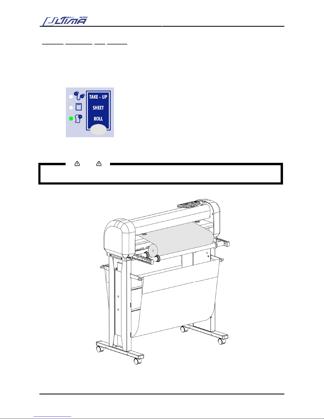
Take-Up / Sheet / Roll
Press the [MEDIA SUPPLY TYPE] key to select how media is loaded.
ARROW-KEY
Press the [ARROW] key for manual movement of the tool head.
LIGHT INDICATORS
LED Description
ORIGIN
Blinks to indicate that you can move the head to replace the origin when you are in
the origin menu.
Lighting indicates that we have a set the origin.
Use the arrow keys to set the origin position by means of the laser led and confirm
with the enter key.
CONTOUR CUTTING
Indicates that an aligning procedure is busy.
TAKE-UP
Indicating that you are working with roll media without front edge detection
SHEET
Indicating that you are working with a sheet of media.
ROLL
Indicating that you are working with roll media using front edge detection
Caution
Please do not use sharp or pointed tools like ballpoints or pencils to press keys. The operation panel is to
be operated with your fingertips.

User’s Guide – Ultima cutting plotter
19 AP-75032, Rev 2.2, 20/04/07
2.6. CONNECTING THE CUTTER TO THE COMPUTER
To make the connection between the cutter and the computer, you are offered two possibilities. The first
possibility is a 2-way RS-232C serial interface. The second possibility is a USB interface.
2.6.1. Serial Interface
The serial RS-232C interface enables the cutter to be connected to and controlled by an RS-232C
compatible host computer system. The cutter is equipped with a standard RS-232C - DB-9P connector on
the rear panel and requires a standard RS-232C DB-9S mating connector.
Step 1 : Make sure both the cutter and the computer are turned off. Connect one end of the serial
interface cable to the serial interface connector at the rear side of the cutting plotter.
Step 2 : Fasten the screws to secure the connector.
Step 3 : Connect the other end of the serial cable to your computer.
Notes
For proper operation of the serial communication, it will be necessary to match the computer settings to the
plotter settings!
9 pin 25 pin 25 pin 9 pin
2.6.2. USB interface
Step 1 : Make sure the USB driver is installed as described in the application guide chapter 1.
Step 2 : Connect one end of the USB cable to the USB connector at the rear side of the cutting plotter.
Step 3 : Connect the other end of the USB cable to your computer or the network.
Notes
Using the serial/USB communication, your cutter will not only be able to receive data from the computer,
but will also be able to send information to the computer (media size, ...).

User’s Guide – Ultima cutting plotter
20 AP-75032, Rev 2.2, 20/04/07
2.7. HOW TO UPGRADE YOUR ULTIMA FIRMWARE
Notes
• Please make sure that the USB driver is installed!
• Please make sure to shut down all programs on your computer before installing new firmware.
Step 1: In case the power is ON, first turn the power of the machine OFF.
Step 2: Connect the Ultima cutting plotter with your PC by means of a USB cable. Remove the RS232
connection.
Step 3: Power ON the Ultima cutting plotter.
Step 4: Go to the “Control Panel – System”.
Step 5: Go to the hardware tab.
Step 6: Press the [Device Manager] button.

User’s Guide – Ultima cutting plotter
21 AP-75032, Rev 2.2, 20/04/07
Step 7: In the “Device Manager” open the list “Ports” (COM & LPT).
Step 8: Check the COM-port number for the USB serial Port (Mutoh Ultima). In the figure above it is
COM3.
Step 9: Start the Ultima update utility on your PC.
Step 10: Select the correct comport (in this case COM3).
Step 11: Press the [Connect] button.

User’s Guide – Ultima cutting plotter
22 AP-75032, Rev 2.2, 20/04/07
Step 12: The status bar starts moving.
Step 13: Press the [Start] button to begin the updating
Step 14: Select the right “.bin” file.
Step 15: The Ultima gives a beep and "Connection with ULTIMA established! Please wait..." is shown in
the update tool.
Step 16: After 13 seconds the message "Sending firmware to ULTIMA!! Please wait...!" appears in the
update tool.
Step 17: The progress bar now starts increasing.
Step 18: The first seconds the progress bar colours red and green. Afterwards the progress bar is black.
Notes
Please note that you passed the critical section of updating when the progress bar is black. When the
machine is shut down in the critical section of the update we refer to the section “When you shut down the
Ultima inside the critical section”.
Step 19: After 1 minute the update finishes with the text "Firmware update successful, restart the
ULTIMA!" on the Ultima update tool.
Step 20: Power OFF the Ultima cutting plotter.
Notes
Please perform a “Code Update” after a firmware upgrade. Without performing a “Code Update”, the panel
keyboard remains in the old firmware version.
Step 21: Restart the Ultima cutting plotter.

User’s Guide – Ultima cutting plotter
23 AP-75032, Rev 2.2, 20/04/07
2.8. CONNECTING THE POWER CABLE
To connect the power cable, please follow the instructions mentioned below.
Step 1 : Make sure the cutter’s power switch is turned OFF.
Step 2 : Plug the plotter-end of the power cable into the connector at the rear of the plotter.
Step 3 : Plug the other end of the power cable into an electrical outlet of the correct voltage and with a
proper grounding.
Notes
The disconnect device is the plug on the power supply cord

User’s Guide – Ultima cutting plotter
24 AP-75032, Rev 2.2, 20/04/07
2.9. INSTALLING A TOOL
At the right-hand side of the cutter head, you will find a pivoting mounting bracket. Opening this bracket will
enable you to install a full range of cutting and drawing tools. To do so, please follow the instructions
mentioned below.
Step 1 : Open the screw (1) to unlock the tool head-mounting bracket.
Step 2 : Hold back the clip (2) of the tool head and slide the tool into position, making sure the tool collar
fits into the groove just beneath the locking screw (3).
Step 3 : Fasten the screw to secure the tool into position.

User’s Guide – Ultima cutting plotter
25 AP-75032, Rev 2.2, 20/04/07
2.10. LOADING MEDIA
When loading media into the cutter, it is necessary to clearly distinguish two situations. The first situation is
when you are using cut-sheet media. The second situation is when you are using roll media.
2.10.1. Loading cut sheet media
Step 1 : Put the pressure rollers (1) in the “up” position using the media hold lever (2) and turn the power
switch ON (3). The cutter will perform its initialization routine and move the tool head (4) to the
rightmost position.
Step 2 : Press the media-select button on the operation panel and select the sheet. After selection the
SHEET-LED will light up.

User’s Guide – Ultima cutting plotter
26 AP-75032, Rev 2.2, 20/04/07
Step 3 : Insert the media into the cutter. It is best to position the media so that half of it hangs in front and
half of it hangs at the back of the cutter.
Step 4 : Adjust the position of the pressure rollers so that they align well with the drive rollers. Doing this
you are helped by the tactile and audible click system for the left pressure roller. The right
pressure roller’s movement is limited so that it can never be malpositioned.
Always make sure that the pressure rollers are completely inside the sheet of the media you want
to load. Especially when you use a cut-sheet of which the corners are not perfectly square, it is
best to put the pressure rollers well inside the vinyl as the width of the sheet may vary.
In case you are using a SC-1400D, you have the opportunity to use either two or three pressure
rollers, depending on the width of the vinyl you are using. When not using the left pressure roller
(i.e. when loading vinyl of a small width), the left pressure roller should be placed at the extreme
left of the cutter (that is, not on top of a grid roller).
Notes
Please note that the middle pressure roller should always be placed on top of a grid roller.
Step 5 : Put the hold lever in the DOWN position.
This action will initialize the media loading sequence, during which the cutter will measure the
loaded sheet. The sheet will be shuffled back and forth, enabling the cutter to determine the
media size and enabling you to verify the media transport.
Step 6 : After finishing the media loading sequence, the tool head will be parked at the origin position and
the cutter will be in ON-LINE mode, ready to receive data from the host computer.
Notes
Do not try to move the pressure rollers when the media hold lever is in the down position as this may cause
damage to the system.
User’s Guide – Ultima cutting plotter
27 AP-75032, Rev 2.2, 20/04/07
2.10.2. Loading roll media
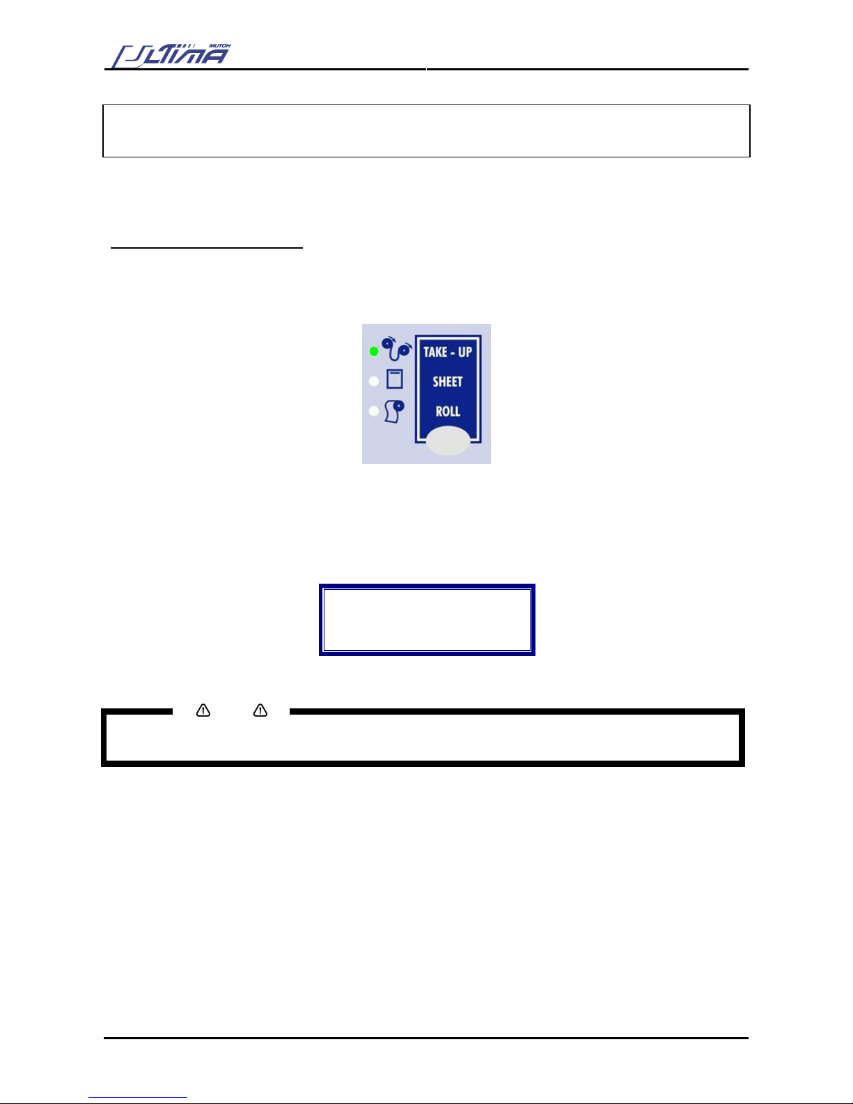
Step 1 : Put the pressure rollers in the “up” position and turn the power switch ON.
The cutter will perform its initialization routine and move the tool head to the rightmost position.
Step 2 : Press the media-select button on the operation panel and select one of the roll loading options.
After selection the ROLL-LED will light up.
Step 3 : Position the roll of media onto the conveyor rolls. Open the protective cover and pull the media
through to be able to choose the best possible position for the pressure rollers.
Notes
Place the media roll on the conveyor rolls as visible on the picture.
To avoid back injuries, the roll of media should be lifted by at least two persons if it’s heavier than 30 kg.

User’s Guide – Ultima cutting plotter
28 AP-75032, Rev 2.2, 20/04/07
Step 4 : Adjust the position of the pressure rollers so that they align well with the drive rollers and that
they can accommodate the roll of vinyl. Doing this, you are helped by the tactile and audible click
system for the left pressure roller. The right pressure roller’s movement is limited so that it can
never be malpositioned. Always make sure that both pressure rollers are at least 5 mm (0.2 inch)
inside the media. It is not recommendable that the rollers run on the very edge of the material.
In case you are using a SC-1400D, you have the opportunity to use either two or three pressure
rollers, depending on the width of the vinyl you are using. When not using the left pressure roller
(i.e. when loading vinyl of a small width), the left pressure roller should be placed at the extreme
left of the cutter (that is, not on top of a grid roller).
Notes
Please note that the middle pressure roller should always be placed on top of a grid roller.
Step 5 : It is best that you hold the front edge of the media in the middle with one hand and with the other
hand, the roll itself.
As you are holding the roll firmly into position, pull the front edge of the media forward so that
there is an even tension across the whole width of the roll.
Step 6 : At this stage, put the hold lever in the DOWN position. Adjust the position of the small conveyor
flanges so that they are just alongside the roll of vinyl. This action will initialize the media loading
sequence, during which the cutter will shuffle a pre-set distance of vinyl. The media will be
shuffled back and forth enabling you to verify the media transport. The page length (pre-feed
length) is factory-set to 1000 mm and can be adjusted by the user.
Step 7 : After finishing the media loading sequence, the tool head will be parked at the origin position and
the cutter will be in ON-LINE mode, ready to receive data from the host computer.
User’s Guide – Ultima cutting plotter
29 AP-75032, Rev 2.2, 20/04/07
2.11. STRAIGHTENING THE VINYL EDGE USING THE AUTOSHEET-OFF UTILITY
The auto-sheet-off mechanism of your cutter can be very easily used to cut the front edge of a new roll of
vinyl straight as well as to cut off a sheet of vinyl from a roll, to be used as a separate sheet.
To do this, proceed as follows:
If you want to sheet-off the vinyl, please follow the instructions below.
Step 1 : Be sure to select take-up with the media supply type key.
Step 2 : Load the media (lever down)
Step 3 : By pressing the Arrow keys, it’s possible to position the media and where to do a sheet off (or
straighten the media)
Step 4 : Press the [SHEET OFF] key. The following message will appear on the operation panel.
Do a sheet-off?
Up = No
Down = Yes
Step 5 : Press the [DOWN] key to confirm. A sheet off will be performed.
Notes
Press the [UP] key to not perform a sheet off.
→ Sheet off mode should be enabled first (Menu Option)

User’s Guide – Ultima cutting plotter
30 AP-75032, Rev 2.2, 20/04/07

User’s Guide – Ultima cutting plotter
31 AP-75032, Rev 2.2, 20/04/07
3. CUTTER CONTROLS
3.1. UNDERSTANDING THE OPERATION PANEL
CANCEL-key
The [CANCEL] key can be used for clearing all received data.
Press the [CANCEL] key to return to the previous setting (without changes).
EXIT/SHEET OFF-key
Press the [EXIT/SHEET OFF] key to go to the previous menu setting.
Press the [EXIT/SHEET OFF] key if you do not want to process the changes in
the cutting settings.
Press the [EXIT/SHEET OFF] key in normal mode to perform a sheet-off.
ENTER/MENU-key
Press the [ENTER-MENU] key to enter the menu system.
Press the [ENTER-MENU] key to confirm the changes made to the setting.
PRESETS-key
Pressing the [PRESETS] key you can choose the active user. Each user has its
own settings that are saved. You can make users for different types of cutting
jobs and so pick the desired settings when necessary by selecting the user.
ORIGIN-key
Use the ARROW keys to set the origin position by means of the laser and confirm
with the [ENTER] key.
Diverse Origin Positions can be set in the Origin Menu (Enter Menu)
L Right (default), L Left, Center, U Right, U left

User’s Guide – Ultima cutting plotter
32 AP-75032, Rev 2.2, 20/04/07
TEST-key
By pressing the [TEST] key you can select one of the test plots out of the list to
cut.
CONTOUR CUTTING-key
In this menu you can start a “manual”, “auto no barcode”, “barcode multi” or
“barcode single” aligning procedure by selecting the desired one of the shown
list.
SPEED-key
Press the [SPEED] key to enter the setting menu to change the cutting speed.
Press the [UP] or [DOWN] key to change the speed. Press the [ENTER] key to
confirm the change. If you do not want to change the speed press the
[CANCEL] or [EXIT] key.
FORCE-key
Press the [FORCE] key to enter the setting menu to change the force.
Press the [UP] or [DOWN] key to change the force. Press the [ENTER] key to
confirm the change. If you do not want to change the force press the [CANCEL]
or [EXIT] key.
Press the [FORCE] key again to cut following picture to verify your force cutting
value.
OFFSET-key
By pressing the [OFFSET] key you can change the offset of the knife:
When you enter this menu you can input the offset or the base offset for cutting
the calibration figures.
When you press the [ENTER] key you get a dialog on the cutter that asks if you
want to do a test cutting (select 1 or 2) or not.
When you perform a test cut, 10 reference pictures around the selected base
offset are cut. You can choose the best one by selecting one of the pictures
with the laser pointer and the [UP] and [DOWN] key.
TOOL-key
Press the [TOOL] key to select:
Knife or Pen
READY / PAUSE-key
By pressing this key you can interrupt the cutting job. When you press the
[READY/PAUSE] key again the cutting job is started again. When no media is
loaded you only can be in pause. When media is loaded the status is ready and
can be changed to pause. When in the pause status (media loaded or not) you
still can send a file to the cutter but it will only responds when you go to ready.

User’s Guide – Ultima cutting plotter
33 AP-75032, Rev 2.2, 20/04/07
UP-key
Press the [UP] key to select a desired value when you are in a menu or a
selection dialog.
DOWN-key
Press the [DOWN] key to select a desired value when you are in a menu or a
selection dialog.
TUSR-key
By pressing this key you can select take-up, sheet or roll media loading system.
The selection can only be done when no media is loaded. (= lever up position)
When media is loaded the LED’s only show which type of media is loaded but
cannot be changed.
Selection Media Initialization Origin position
Take-Up Right, left + pre-feed At X-loading position
Sheet Right, left + Front + Back Search distance will be the
maximum sheet length.
Origin position at the front
Roll Right, left + Front + Pre-feed At the front
In case the pre-feed value is larger than the sheet length
→ Auto swap from Roll to Sheet
ARROW-key
The [ARROW] keys are always active, the cutter being ONLINE or OFFLINE.
To enable the user to manually move the tool head and the media. This can be
necessary in order to examine specific details of the sign or to set a new origin.
When pressing the [LEFT ARROW] or [RIGHT ARROW] key, the head will move
accordingly. It will move slowly for two seconds and speed up afterwards.
When pressing the [TOP ARROW] or [BOTTOM ARROW] key, the media (if
loaded) will move accordingly. It will move slowly for 2 seconds and speed up
afterwards.
When pressing two [ARROW] keys simultaneously the head will move relative
diagonal to the media.
ORIGIN LED
Lights when alternative origin is selected.
Blinks when changing origin.
CONTOUR CUTTING LED
Blinks when executing alignment procedure.
TAKE-UP LED
This LED will light up if you have selected to load roll media without front edge
detection.

User’s Guide – Ultima cutting plotter
34 AP-75032, Rev 2.2, 20/04/07
SHEET LED
This LED will light up if you selected Sheet Media.
ROLL MEDIA LED
This LED will light up if you selected the Roll Media.
DISPLAY
4 lines / 16 characters
Displays the LCD-display messages, shows settings/values
and allows menu-wise control.
User’s Guide – Ultima cutting plotter
35 AP-75032, Rev 2.2, 20/04/07
3.2. DIRECT KEY ACCESS
On the operation panel are keys to directly change or control some values of the Ultima cutting plotter.
Following items can be changed / controlled directly via the operation panel.
No Function Description Short-key
1 Force Control/change the force of the Ultima. [FORCE] key
2 Speed Control/change the speed of the Ultima. [SPEED] key
3 Offset Control/change the offset of the Ultima. [OFFSET] key
4 Tool Control/change the tool setting of the Ultima. [TOOL] key
5 Origin Control/change the origin of the Ultima [ORIGIN] key
6 Contour Cutting In this menu you can start an “manual”, “auto no
barcode”, “barcode multi” or “barcode single”
alignment procedure.
[CONTOUR CUTTING] key
7 Test Perform one of the test plots onto the Ultima. [TEST] key
8 Presets Select an user previously saved in the Ultima
cutting plotter.
[PRESETS] key
3.2.1. Force selection
Tool force
is the amount of downward pressure that the cutter applies on the tool.
To change or control the tool force, please perform the instructions mentioned below.
Step 1 : Press the [FORCE] key.
Step 2 : The actual FORCE setting for the selected tool will now be shown on the display. Viewing of the
value can be performed in PAUSE as well as in READY mode.
Force
Actual : 30
New : 30
In gram
Step 3 : Press the [UP] or [DOWN] key to change the force setting.
Step 4 : Press the [FORCE] key. The Ultima will cut following picture.
Step 5 : Check the patterns. Especially look for good quality of the corners and easy weeding. If this is
not the case readjust the FORCE selection.
Step 6 : Press the [ENTER] key to confirm the FORCE selection.
Notes
To cancel the changes of the parameter, press the [CANCEL] key. The display will show the previous
value for the parameter.
When you press the [EXIT] key the changed value will be ignored and you go back to the previous menu.

User’s Guide – Ultima cutting plotter
36 AP-75032, Rev 2.2, 20/04/07
3.2.2. Speed selection
To change / control the cutting speed, please perform the instructions mentioned bow.
Step 1 : Press the [SPEED] key.
Step 2 : The actual SPEED setting for the selected tool will now be shown on the display. Viewing of the
value can be performed in PAUSE as well as in READY mode.
Speed
Actual : 10
New : 10
In cm/s
Notes
Changing/viewing of the value can be performed in BUSY mode. Please note that the effect can only be
seen after a few seconds.
Notes
Toolup / laser speed is independent of the cutting speed.
Step 3 : Press the [UP] or [DOWN] key to change the force setting.
Step 4 : Press the [ENTER] key to confirm the SPEED selection.
Notes
To cancel the changes of the parameter, press the [CANCEL] key. The display will show the previous
value for the parameter.
When you press the [EXIT] key the changed value will be ignored and you go back to the previous menu.
3.2.3.
Offset selection
One of the most important factors to obtain good quality, but unfortunately also one of the factors that is
easily forgotten, is the offset.
For more information about the offset, please refer to the chapter ‘Fine-tuning your cutter to obtain Mutoh
quality’.

User’s Guide – Ultima cutting plotter
37 AP-75032, Rev 2.2, 20/04/07
3.2.4. Tool selection
To change / control the tool selection, please perform the instructions mentioned bow.
Step 1 : Press the [TOOL] key.
Step 2 : The actual TOOL setting for the Ultima cutting plotter will be shown on the display. Viewing of
the value can be performed in PAUSE as well as in READY mode.
Tool
Actual : knife
New : knife
Pen or knife
Step 3 : Press the [UP] or [DOWN] key to change the force setting. You can choose between ‘pen’ and
‘knife’.
Notes
Please make sure the tool selected onto the display is the same as the installed tool in the Ultima cutting
plotter.
Step 4 : Press the [ENTER] key to confirm TOOL selection.
Notes
To cancel the changes of the parameter, press the [CANCEL] key. The display will show the previous
value for the parameter.
When you press the [EXIT] key the changed value will be ignored and you go back to the previous menu.
3.2.5. Origin selection
To change / control the origin, please perform the instructions mentioned bow.
Notes
Please make sure media is loaded. If not, the Ultima positioning calculation is based on previously installed
media.
Step 1 : Press the [ORIGIN] key.
Step 2 : The laser LED will be activated automatically. The display will show following message:
Point laser to
Desired origin
Position
Enter = Confirm
Step 3 : Use the arrow keys to move the laser to the desired origin position and press the [ENTER] key.

User’s Guide – Ultima cutting plotter
38 AP-75032, Rev 2.2, 20/04/07
3.2.6. Test selection
In order to enable the user to check if the cutter is fully functional, without needing a computer, MUTOH has
integrated demo test cuts into the Ultima cutters.
For more information about the test cuts, please refer to the chapter ‘Fine-tuning your cutter to obtain Mutoh
quality’.
3.2.7. Presets selection
Using the presets makes it possible to store settings (all settings that can be changed from the panel) for
specific cutting jobs.
In the presets menu following options are available.
¾ Select Preset : Use this function to select a previously saved user setting.
¾ Reset : Change a saved user setting to a default value based on Mutoh’s values.
¾ Add : Add a new user setting.
¾ Remove : Remove a previously saved user setting.
3.2.7.1. ‘Select Presets’
Use this function to select a previously saved user setting. Please follow the instructions mentioned below.
Step 1 : Press the [PRESETS] key.
Step 2 : Following message will appear on the display.
Presets
Select presets
Choose user
Step 3 : Press the [ENTER] key. Following message will appear on the display.
→ User 1
Enter = select
↑ = Up
↓ = Down
Step 4 : Use the [UP] or [DOWN] key to select a user setting.
Step 5 : Press the [ENTER] key to confirm the selected user setting. The Ultima cutting plotter will load
the requested user settings.
Notes
To cancel the changes of the parameter, press the [CANCEL] key. The display will show the previous
value for the parameter.
When you press the [EXIT] key the changed value will be ignored and you go back to the previous menu.

User’s Guide – Ultima cutting plotter
39 AP-75032, Rev 2.2, 20/04/07
3.2.7.2. ‘Reset’
Use this function to change a saved user setting to a default value based on Mutoh’s values. Please follow
the instructions mentioned below.
Step 1 : Press the [PRESETS] key.
Step 2 : Use the [UP] or [DOWN] key to select the following display.
Presets
Reset
Choose user
Step 3 : Press the [ENTER] key. Following message will appear on the display.
→ Monomeric vinyl
Enter = select
↑ = Up
↓ = Down
Step 4 : Use the [UP] or [DOWN] key to select a setting based on Mutoh’s values.
Step 5 : Press the [ENTER] key to confirm the selected user setting. The Ultima cutting plotter will load
the requested settings into the active user setting. The active user setting will now have the
settings based on Mutoh’s values.
Notes
To cancel the changes of the parameter, press the [CANCEL] key. The display will show the previous
value for the parameter.
When you press the [EXIT] key the changed value will be ignored and you go back to the previous menu.
3.2.7.3. ‘Add’
To add a new user setting, please follow the instructions below.
Step 1 : Change all settings for the specific cutting job you will perform.
Step 2 : To store all these settings, press the [PRESETS] key.
Step 3 : Use the [UP] or [DOWN] key to select the following display.
Presets
Add
Choose user
Step 4 : Press the [ENTER] key. The Ultima cutting plotter will store all settings in a new user setting.
Notes
To cancel the changes of the parameter, press the [CANCEL] key. The display will show the previous
value for the parameter.
When you press the [EXIT] key the changed value will be ignored and you go back to the previous menu.

User’s Guide – Ultima cutting plotter
40 AP-75032, Rev 2.2, 20/04/07
3.2.7.4. ‘Remove’
To remove a previously saved user setting, please follow the instructions mentioned below.
Step 1 : Press the [PRESETS] key.
Step 2 : Use the [UP] or [DOWN] key to select the following display.
Presets
Remove
Choose user
Step 3 : Following display will appear.
→ User 1
Enter = select
↑ = Up
↓ = Down
Step 4 : Use the [UP] or [DOWN] key to select the user setting you want to delete.
Step 5 : Press the [ENTER] key to confirm. The Ultima cutting plotter will delete the selected user setting.
Notes
To cancel the changes of the parameter, press the [CANCEL] key. The display will show the previous
value for the parameter.
When you press the [EXIT] key the changed value will be ignored and you go back to the previous menu.

User’s Guide – Ultima cutting plotter
41 AP-75032, Rev 2.2, 20/04/07
3.3. CONTOUR CUTTING
Contour cutting is without doubt the most used feature of the Ultima Cutting Plotter. This feature is made to
cut pre-printed signs on vinyl for sticker production.
Before using this feature, perform the epos alignment as described in chapter 5.6.8.1.
3.3.1. Aligning methods
There are some different approaches to cut your signs which also implicate a different alignment method.
To perform and choose the proper alignment, please follow the instructions mentioned below.
Step 1 : Load the printed media into the cutting plotter.
Step 2 : Install a knife.
Step 3 : Power ON the cutting plotter. The cutting plotter will perform a shuffle sequence.
Step 4 : Press the [CONTOUR CUTTING] key.
Contourcutting :
Methods :
→ BCode Single
Start alignment
Step 5 : By using the [UP] and [DOWN] key you select ‘Manual’, ‘Auto No BCod’, ‘BCode Multi’ or ‘BCode
Single’.
4 methods are possible for aligning:
1) Manual Manual align (MP1)
2) Auto No Bcod Automatic aligning, No Barcode (AL3)
3) Bcode Single Automatic align Barcode Single frame (AL4)
4) Bcode Multi Automatic align Barcode Multi-segment (AL5 or AL6)
Each one of these methods has its own cropmark system (see below)
MP 1 AL 3 AL 4 AL 5

User’s Guide – Ultima cutting plotter
42 AP-75032, Rev 2.2, 20/04/07
Step 6 : Before performing an alignment, ‘X Length’, ‘Y Width’ and ‘Roll Direction’ must be inserted. With
these values the Ultima cutting plotter will calculate the E-pos correction.
Step 7 : Press the [CONTOUR CUTTING] key. On the display following message will appear.
Contourcutting :
X Length (mm) :
→ 500
Start alignment
Step 8 : By using the [UP] and [DOWN] key you select an appropriate value for the X Length.
Notes
Please make sure that the value of the X Length is smaller than the length of the loaded media. Otherwise,
the Ultima cutting plotter cannot complete the alignment – NO VALID EPOS REFERENCE FOUND.
Step 9 : Press the [CONTOUR CUTTING] key to confirm. On the display following message will appear.
Contourcutting :
Y Width (mm) :
→ 500
Start alignment
Step 10 : By using the [UP] and [DOWN] key you select an appropriate value for the Y Width.
Step 11 : Press the [CONTOUR CUTTING] key to confirm. On the display following message will appear.
Contourcutting :
Roll direction
→ Non-reverse
Start alignment
Step 12 : Select the appropriate ‘roll direction’ (non-reverse or reverse) by using the [UP] and [DOWN] key.
Step 13 : Press the [CONTOUR CUTTING] key to check the entered values of the ‘X length’, ‘Y width’ and
‘roll direction’.
Step 14 : To confirm your settings press the [ENTER] key.
Step 15 : The Ultima cutting plotter will start the frame detection. (‘Manual’ or ‘automatic’ as selected in
step 5).

User’s Guide – Ultima cutting plotter
43 AP-75032, Rev 2.2, 20/04/07
In case you selected ‘Auto No BCode’.
Step 15 : The Ultima cutting plotter will automatically measure the four alignments points.
In case you selected ‘Manual’.
Step 15 : After pressing the [ENTER] key following message will appear on the display.
Manual alignment
method
please select
the point
Step 16 : Use the [ARROW] keys to select the first alignment point (P1). Press the [ENTER] key to
perform.
Step 17 : The Ultima cutting plotter will move the head toward the second alignment point. On the display
following message will appear.
Manual alignment
method
please select
the point
Step 18 : Use the [ARROW] keys to select the second alignment point (P2). Press the [ENTER] key to
perform.
Step 19 : The Ultima cutting plotter will move the head toward the third alignment point. On the display
following message will appear.
Manual alignment
method
please select
the point
Step 20 : Use the [ARROW] keys to select the fourth alignment point (P4). Press the [ENTER] key to
perform
Step 21 : The Ultima cutting plotter will move the head toward the fourth alignment point. On the display
following message will appear.
Manual alignment
method
please select
the point
Step 22 : Use the [ARROW] keys to select the third alignment point (P3). Press the [ENTER] key to
perform.
Step 23 : Manual alignment is completed.
Notes
Make sure to keep the order of the alignment points. P1, P2, P4 and then P 3
User’s Guide – Ultima cutting plotter
44 AP-75032, Rev 2.2, 20/04/07
In case you selected ‘BCode Single’
Step 15 : Press the [MENU ▲] key to choose BCode Single.
Step 16 : Press the [CONTOUR CUTTING] button again.
Contourcutting:
→ Repeat Mode
Start Aligning
Step 17 : With the [MENU ▲] key to choose “Single Scan” or “Repeat Mode”.
Notes
> Single Scan: The command will be given to start scanning the bar code of the first / next bounding box
ONLY, from roll or sheet. After finishing this single job, the Ultima returns into the Ready status.
> Repeat Mode: AUTOMATICALLY all succeeding frames will be scanned and contour cut as well, until the
end of roll is reached.
Step 18 : Press the [ENTER] key to start.
In case you selected ‘BCode Multi’
Step 15 : Press the [MENU ▲] key to choose BCode Multi.
Step 16 : Press the [CONTOUR CUTTING] button again.
Contourcutting:
→ Single Scan
Start Aligning
Step 17 : With the [MENU▲] key to choose “Single Scan” or “Repeat Mode”.
Notes
> Single Scan: The command will be given to start scanning the bar code of the first / next bounding box
ONLY, from roll or sheet. After finishing this single job, the Ultima returns into the Ready status.
> Repeat Mode: AUTOMATICALLY all succeeding frames will be scanned and contour cut as well, until the
end of roll is reached.
Step 18 : Press the [ENTER] key to start.

User’s Guide – Ultima cutting plotter
45 AP-75032, Rev 2.2, 20/04/07
3.3.2. Which Aligning Method should I use?
The MP1 (Mutoh Manual Align Method) is the non-automatic method.
Its advantage is that the cropmark system is very small (for small sized jobs), and that this method can be
used in case of vinyl that do not reflect the laser light (meaning, the laser would not be capable of measuring
the cropmarks automatically).
The user has to use the jog keys on the Ultima’s keyboard to measure each cross manually before
contourcutting can start.
The AL3 (Mutoh Auto Align) is the first fully-automated alignment system.
Just place the sign in the cutter, click on PLOT in the cutting software, and the cutter will automatic align the
sign by use of the black bounding box, no user intervention is needed.
This method is ideal for use of single signs, one at the time.
We do not advise to use this method for signs over 2 meter of length, although there is no real limit to the
length that can be used.
The AL4 (Mutoh Auto Align Barcode) is similar to the AL3 method, but there is barcode printed on
the sign.
YOU MUST USE THIS METHOD IN COMBINATION WITH THE CUTSERVER!
This method can be used in case you are creating multiple different contour signs. It allows you to make all
your prints at once (overnight printing for example), and then load the roll with images in the Ultima.
If each sign on the roll has a barcode and if all plot files are in the CutServer, just click on GO in the
CutServer (make sure that the CutServer properties are set to SINGLE FRAME, and REPEAT MODE) and
every sign on the roll will be cut, without the need for user intervention (make sure you’ve enabled autosheet-off in EasySIGN for each contour-sign)
The reason for the two barcodes is to make it possible for the Ultima to auto-detect if the image is loaded
upside-down or correctly.
There is no need for you to search the plot file for each image, the Ultima and the CutServer will do this fullyautomatically, until the complete roll with signs is finished.
We do not recommend this method over 2 m job length, although there is no real limit to the length that can
be used.
The AL5 (Mutoh Auto Align Multiframe) offers all advantages of the AL4 and AL3 method, but it will
split the image in multiple segments of maximum 50cm. (This is to enhance precision over long length).
With AL5, it is possible to make signs of 10m or longer, and the Ultima will measure segment per segment,
and cut segment per segment. This method gives you more accuracy than the AL4 method. We do not
recommend this method for signs smaller than 1,5m
You should use the CutServer for this method, and make sure the CutServer properties are set to MULTIFRAME MODE. (Single scan for 1 AL5 file and Repeat mode for a roll with multiple AL5 files).
Notes
For more details about the Print & Cut workflow and CutServer, please refer to the Application Guide in
the box.

User’s Guide – Ultima cutting plotter
46 AP-75032, Rev 2.2, 20/04/07
3.4. SQUARE DETAILS
Notes
Please note that the creation of an image should be done in a graphics application software (e.g.
CorelDraw, Adobe Illustrator, Adobe Photoshop or Macromedia Freehand) or in origin software with design
functionalities (EasySIGN Power Pack Pro Mutoh Edition or Scanvec Amiable PhotoPRINT DX Mutoh
Edition)
Notes
Do not forget to create the cutting line around your image. The default cutting line is a “magenta hairline” or
“spotcolor” with <CutContour> swatch name (in the CMYK pallet).
→ Thickness line = hairline (or 0.25)
→ Colour = 100% magenta
For more details, please refer to the Application Guide.
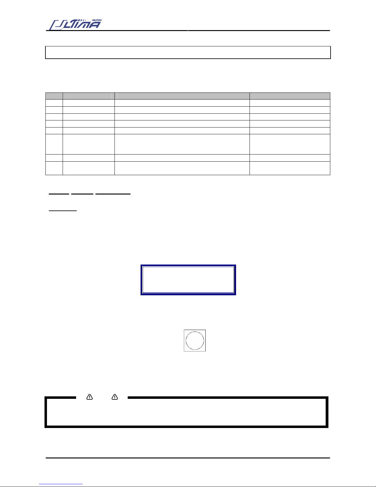
To use the automatic alignment procedure, the pre-printed sheet contains a Bounding Box (*) around the
design to be cut. Details can be found below.
VINYL
Bounding Box. This Bounding Box should have a minimum
thickness of 3 mm; default value of this square is 5 mm thick.
Please leave a white edge of 20 mm in front. The sensor firstly
detects the white space.
(*) Please note that the Bounding Box around your design(s) will be printed. Before contour-cutting the Epos technology will search for the Bounding Box and measure the position of the design(s).
The Bounding Box should be at least an A4 format (Portrait). There must be 5 mm white space between the
image and the Bounding Box. Make sure that the Bounding Box is colored black. (→ Contrast) Make sure
that the Bounding Box fits within the margins of the maximum cutting width of your cutting plotter.
Notes
Please note that the position of the design with the Bounding Box compared to the page edges is defined in
the print-software.

User’s Guide – Ultima cutting plotter
47 AP-75032, Rev 2.2, 20/04/07
The square will be detected on the following points.
110 mm or more for a cut-sheet or for the roll end.
Between consecutive boxes: 30 mm – 250 mm
(recommended 65 mm)
5 mm white space
between bounding box
and drawing
Min. side margin of 10
mm.
VINYL
Min. side margin of 10
mm
Black bounding box:
Line thickness of 3
mm-30mm
Default value 5 mm
Minimum size of A4
(Portrait)
Maximum colour
contrast with media.
Min. front margin of 10 mm / max. 250 mm
Notes
When measuring the four points of the box and the cutter establishes a distortion (this means the box is not a
perfect rectangle due to print deformation, or not between the margins), the cutter will beep and shows
following message:
EPOS-warning
********************
Much print
distortion
The cutter will cut a little cross in the lower right corner to remind you and us to its bad print quality in case of
bad contour cutting; however it will continue its workflow after two seconds.
Please refer to next chapter “Print Deformation” for more details.

User’s Guide – Ultima cutting plotter
48 AP-75032, Rev 2.2, 20/04/07
3.5. SPECIAL FUNCTIONS FOR QUALITY
3.5.1. EPOS offset fine-tune
This function is made to fine-tune the EPOS offset.
Please follow the steps below to perform a fine-tune
Step 1 : Install a knife.
Step 2 : Press the [TOOL] key and select ‘knife’.
Step 3 : Load media
Step 4 : Activate the “EPOS offset fine-tune” function by pressing the [TEST] + [CONTOURCUTTING]
button simultaneously. This function is only accurate for 1 job.
EPOS fine-tune
selected for
next job
press any key
Step 5 : Send contour job to the plotter.
Step 6 : The cutter will start cutting 11 lines on the bottom of the box.
Step 7 : When pressing the [UP] or [DOWN] key, the laser goes to the next line. Following message is
displayed
Offset: 0.00
Enter = Select
▲ = Up
▼ = Down
Notes
You can also use the [ARROW] keys
Step 8 : Press the [ENTER] key when laser is above the line which lies on the bottom side of the box.

User’s Guide – Ultima cutting plotter
49 AP-75032, Rev 2.2, 20/04/07
Step 9 : The cutter will start cutting 11 lines on at the right side of the box.
Step 10 : When pressing the [UP] or [DOWN] key, the laser goes to the next line. Following message is
displayed
Offset: 0.00
Enter = Select
▲ = Up
▼ = Down
Notes
You can also use the [ARROW] keys
Step 11 : Press the [ENTER] key when laser is above the line which lies on the right side of the box.
Step 12 : The EPOS offset fine-tune is finished.

User’s Guide – Ultima cutting plotter
50 AP-75032, Rev 2.2, 20/04/07
3.5.2 Print deformation
This function is a warning. Following message could appear when the printed box on the vinyl or other media
is deformed. This means, not a perfect rectangle.
The Ultima can not guarantee a perfect cut workflow when the box is deformed.
When measuring the four points of the box and the cutter establishes a distortion, the cutter will beep and
shows following message:
EPOS-warning
********************
Much print
distortion
The cutter will cut a little cross in the lower right corner and will continue its workflow after two seconds.

User’s Guide – Ultima cutting plotter
51 AP-75032, Rev 2.2, 20/04/07
4. CUTTER SETTINGS & SPECIAL
FUNCTIONS
4.1. GENERAL PROCEDURE TO CHANGE SETTINGS ON THE
CUTTER
Not only there are keys to directly change or control some values of the Ultima cutting plotter, but more
settings are available by following the instructions mentioned below.
Step 1 : Pressing the [ENTER] key, the user enters the setup-menu.
Step 2 : Pressing the [UP] or [DOWN] key, the user can select the parameter he wants to adjust. Confirm
with the [ENTER] key the selection.
Step 3 : The [UP] key will increase the value or select the next parameter. The [DOWN] key will decrease
the value or select the previous parameter. Press the [ENTER] key to confirm the new setting.
After confirmation the display will show the previous menu.
Notes
To cancel the changes of the parameter, press the [CANCEL] key. The display will show the previous
value for the parameter.
When you press the [EXIT] key the changed value will be ignored and you go back to the previous menu.
Step 4 : Press the [EXIT] key to go back to the previous menu and confirm the changed settings.
4.2. OVERVIEW OF GENERAL SETTINGS
The general settings parameter influences the cutter’s reactions to commands given by the computer or
initiated via the control panel. In the general settings menu, several parameters are available:
→
Sheet Off Mode
→
Sheet Off Margin
→
Pre-Feed Length
→
Max Sheet Length
→
Page Mode
→
Laser Speed
→
Tool-Up Speed
→
Cut Quality
→
Factory Default
→
Copies
→
Smoothing
→
Bézier
→
Language
→
Emulation
→
Program Step
→
VS / ZF / AS
→
Communication

User’s Guide – Ultima cutting plotter
52 AP-75032, Rev 2.2, 20/04/07
4.2.1. Sheet Off Mode
With the sheet-off mode, you can select “AUTOMAT”, “MANUAL” or “DISABLE”.
Automatic A sheet-off can be done when pressing the “Exit-Sheet OFF” key.
Manual A sheet-off can be done with a snap-off blade knife; the paper will feed towards the cutgroove.
Disable No sheet-off can be done
The auto-sheet-off mechanism of your cutter can be very easily used to cut the front edge of a new roll of
vinyl straight as well as to cut off a sheet of vinyl from a roll, to be used as a separate sheet. Please refer to
2.11.
To perform sheet off, proceed as follows:
Step 1 : In the general setting select ‘Sheet Off Mode’ by using the [UP] or [DOWN] key.
Step 2 : Press the [ENTER] key to confirm your selection. The actual Sheet Off Mode will now be shown
on the display
Sheet Off
Actual : AUTOMAT
New : AUTOMAT
Sheet Off Mode
Step 3 : By using the [UP] or [DOWN] key select “Automat”, “Manual” or “Disable”.
Step 4 : Press the [ENTER] key to confirm.
Notes
To cancel the changes of the parameter, press the [CANCEL] key. The display will show the previous
value for the parameter.
When you press the [EXIT] key the changed value will be ignored and you go back to the previous menu.
Notes
When pressing the [EXIT-SHEET OFF] key for a while, following message will appear.
Do a sheet off?
▲ = No
▼ = Yes
This message will only appear when Sheet Off Mode is enabled.

User’s Guide – Ultima cutting plotter
53 AP-75032, Rev 2.2, 20/04/07
4.2.2. Sheet Off Margin
With the sheet-off margin, you can select a value from 1 mm to 250 mm. Before performing a sheet-off the
Ultima cutting plotter will forward the media equally to the selected margin.
To do this, proceed as follows:
Step 1 : In the general setting select ‘Sheet Off Margin’ by using the [UP] or [DOWN] key.
Step 2 : Press the [ENTER] key to confirm your selection. The actual Sheet Off Margin will now be shown
on the display
Sheet Off Margin
Actual : 5
New : 5
Margin (mm)
Step 3 : By using the [UP] or [DOWN] key select an appropriate value.
Step 4 : Press the [ENTER] key to confirm.
Notes
To cancel the changes of the parameter, press the [CANCEL] key. The display will show the previous
value for the parameter.
When you press the [EXIT] key the changed value will be ignored and you go back to the previous menu.
4.2.3. Pre-Feed Length
This parameter is directly related to the loading of ROLL media. The Pre-Feed length or SHUFFLE length
has to be set before a roll is loaded.
There are three reasons for using a Pre-Feed Length :
1. The length of media set for the Pre-Feed length parameter will be pulled off the roll, before the
cutting job commences. This will prevent media from being pulled off the roll at high speed and
acceleration. High speed can only be properly used on condition that the media can move freely,
without having to be pulled off the roll during a job.
2. Before actually cutting starts the complete length of the media is shuffled back and forth through the
cutter, ensuring that the pressure rollers have a discrete path while the user has the time to verify if
the vinyl transport goes well.
3. Your Ultima cutter has been equipped with MUTOH’s unique AUTO-SHEET-OFF feature, to
automatically cut off media at the end of a cutting sequence. Following an automatic PAGE
command or a manual PAGE command initiated via the control panel, the cutter will shuffle through
the pre-set Pre-Feed length of media, to ensure that their is enough media left for a possible replot.
If there is not enough media left, the cutter will stop before the end of the assigned media length.

User’s Guide – Ultima cutting plotter
54 AP-75032, Rev 2.2, 20/04/07
To change the value of the Pre-Feed Length, please follow the instructions mentioned below.
Step 1 : In the general setting select ‘Pre-Feed Length’ by using the [UP] or [DOWN] key.
Step 2 : Press the [ENTER] key to confirm your selection. The actual Pre-Feed Length will now be shown
on the display
Pre-Feed Length
Actual : 940
New : 940
Pre-Feed (mm):
Step 3 : By using the [UP] or [DOWN] key select an appropriate value.
Step 4 : Press the [ENTER] key to confirm.
Notes
To cancel the changes of the parameter, press the [CANCEL] key. The display will show the previous
value for the parameter.
When you press the [EXIT] key the changed value will be ignored and you go back to the previous menu.
Notes
Please note that the use of the PRE-FEED LENGTH should not be regarded as a loss of time. If the shuffle
movement is executed without difficulty, the user can be convinced that the sign to be cut will be executed
with very little risk of media tracking problems. As such, it will result in a time-saving operation, preventing
that the user will have to re-cut a very complex design because of bad media alignment.
Notes
Please note that the cutting range is not limited by the Pre-Feed Length which you have set. In case a
design which exceeds the shuffle length is sent to the cutting plotter, the cutter will react as follows:
The first vector, which exceeds the limit, will be cut using reduced speed for the distance exceeding the
limit.
An additional 20 cm (8 inch) of media will be pulled off the roll in order to eliminate any possible snagging at
the roll.
After the additional (20 cm) pre-feed the cutter will continue at the requested speed until the new limit is
exceeded.
However, this should not be a reason for you not to change the page length at all, as by omitting to change
it; you will be inhibited to check the full vinyl transport before the job is launched

User’s Guide – Ultima cutting plotter
55 AP-75032, Rev 2.2, 20/04/07
4.2.4. Max Sheet length
After installation of a sheet (and sheet is selected in the menu) the Ultima cutting plotter will measure the
width and length of the sheet.
In case sheet is selected in the menu but roll media is loaded the Ultima will measure the length of the roll.
This is not the intension. Therefore, you can select a Max Sheet length value. In case sheet is selected in
the menu, the Ultima will not measure more than the length selected in the Max Sheet length menu,
preventing roll media to be rolled off completely.
To change the value of the Max Sheet length, please follow the instructions mentioned below.
Step 1 : In the general setting select ‘Max Sheet length’ by using the [UP] or [DOWN] key.
Step 2 : Press the [ENTER] key to confirm your selection. The actual Pre-Feed Length will now be shown
on the display
Max sheet length
Actual : 5000
New : 5000
Sheet length (mm)
Step 3 : By using the [UP] or [DOWN] key select an appropriate value.
Step 4 : Press the [ENTER] key to confirm.
Notes
To cancel the changes of the parameter, press the [CANCEL] key. The display will show the previous
value for the parameter.
When you press the [EXIT] key the changed value will be ignored and you go back to the previous menu.

User’s Guide – Ultima cutting plotter
56 AP-75032, Rev 2.2, 20/04/07
4.2.5. Page Mode
The page mode determines the cutter’s reaction to a PAGE command sent by the cutting software. The
PAGE command is a command, which is used to relocate the origin after a job is finished and which can take
control remotely of the cutter’s automatic sheet-off feature. Sheeting-off automatically, without user
intervention, is a feature which is unique to Mutoh cutting-plotters and which enhances the cutter’s versatility
and overall performance enormously.
A page-command looks like this: “PG;” or “Pgn;” with “n” a number in millimeters.
If the PAGE command “PG;” is sent, the cutter will automatically sheet of regardless of the Page mode,
minimizing the loss of vinyl.
If the PAGE command “Pgn;” is sent, the number mentioned after the PG command will be interpreted
differently, depending on the page mode you have chosen :
Page Mode 0 :
The number after the page command is ignored. The media will be cut 5 mm (0.2”) after the latest vector.
The new cutting limit will be located 0.5 (0.2”) from the lower media border.
Page Mode 1 :
The new origin is located “n” millimeters beyond the last vector that was sent.
Page Mode 2 :
The new origin is located “n” millimeters beyond the previous origin position.
“PGn” is sent (n is a number in mm).
A : Original origin
B : End point last vector
C : New origin with Page Mode 1
D : New origin with Page Mode 2
To change the Page Mode, please follow the instructions mentioned below :
Step 1 : In the general setting select ‘Page Mode’ by using the [UP] or [DOWN] key.
Step 2 : Press the [ENTER] key to confirm your selection. The actual Page Mode value will now be
shown on the display
Page Mode
Actual : 1
New : 1
0, 1 or 2
Step 3 : By using the [UP] or [DOWN] key select an appropriate value.
Step 4 : Press the [ENTER] key to confirm.
Notes
To cancel the changes of the parameter, press the [CANCEL] key. The display will show the previous
value for the parameter.
When you press the [EXIT] key the changed value will be ignored and you go back to the previous menu.

User’s Guide – Ultima cutting plotter
57 AP-75032, Rev 2.2, 20/04/07
4.2.6 Origin
To change / control the default origin after a media load sequence, please perform the instructions
mentioned bow.
Notes
Please make sure media is loaded. If this is not the case, the Ultima positioning calculation is based on
previously installed media.
Step 1 : Select [ORIGIN] menu.
Step 2 : The actual ORIGIN setting for the selected tool will now be shown on the display. Viewing of the
value can be performed in PAUSE as well as in READY mode.
Origin type :
Actual : LRIGHT
New : LRIGHT
Set new origin
Step 3 : Press the [UP] or [DOWN] key to change the origin setting. Values are: L RIGHT, CENTER, L
LEFT, U LEFT, U RIGHT or MANUAL.
Step 4 : In case you have selected ‘CENTER’, ‘L RIGHT’, ‘L LEFT’, ‘U LEFT’ or ‘U RIGHT’, press the
[ENTER] key to confirm the ORIGIN selection. The head will move to the requested position.
Step 5 : In case you use the shortcut key [ORIGIN], the beam will automatically activate, and you can use
the [ARROW] keys to position the head to the requested origin. Press the [ENTER] key to
confirm the ORIGIN
Notes
To cancel the changes of the parameter, press the [CANCEL] key. The display will show the previous
value for the parameter.
When you press the [EXIT] key the changed value will be ignored and you go back to the previous menu.
4.2.7. Laser Speed
It is possible to perform a test contour cutting with the Ultima cutting plotter. Contour lines will be indicated
by the laser beam. In case the speed of the test contour cutting is not acceptable, you can decrease or
increase the speed.
To change the Laser Speed, please follow the instructions mentioned below:
Step 1 : In the general setting select ‘Laser Speed’ by using the [UP] or [DOWN] key.
Step 2 : Press the [ENTER] key to confirm your selection. The actual Laser Speed value will now be
shown on the display
Laser Speed
Actual : 10
New 10
In cm/s

User’s Guide – Ultima cutting plotter
58 AP-75032, Rev 2.2, 20/04/07
Step 3 : By using the [UP] or [DOWN] key select an appropriate value.
Step 4 : Press the [ENTER] key to confirm.
Notes
To cancel the changes of the parameter, press the [CANCEL] key. The display will show the previous
value for the parameter.
When you press the [EXIT] key the changed value will be ignored and you go back to the previous menu.
Notes
The laser speed has nothing to do with the speed of measuring a frame.
4.2.8. Tool-up Speed
Tool-up movements are mostly long movements (which reach their maximum speed) between the short tooldown movements. These movements could cause abrupt media transport (which could cause tracking
problems). Therefore, it is recommended to select a tool-up speed lower than the speed selection in the
menu.
Notes
In case the Tool-up speed is higher than the speed. The Tool-up speed will be set automatically to the
value of the speed.
Notes
The tool-down speed is related to the value selected in the speed menu.
You can change the tool-up speed in the menu.
To change the Tool-up Speed, please follow the instructions mentioned below:
Step 1 : In the general setting select ‘Tool-up Speed’ by using the [UP] or [DOWN] key.
Step 2 : Press the [ENTER] key to confirm your selection. The actual Tool-up Speed value will now be
shown on the display
Tool-up Speed
Actual : 100
New : 100
In cm/s
Step 3 : By using the [UP] or [DOWN] key select an appropriate value.
Step 4 : Press the [ENTER] key to confirm.

User’s Guide – Ultima cutting plotter
59 AP-75032, Rev 2.2, 20/04/07
4.2.9. Cut Quality
You can choose a level of quality in the menu.
¾ Draft
¾ Normal
¾ High
Notes
This value has effect only on the ‘acceleration’ value.
The lower the acceleration → the higher the quality but the lower the throughput.
The higher the acceleration → the higher the throughput but the lower the quality.
To change the Cut Quality, please follow the instructions mentioned below :
Step 1 : In the general setting select ‘Cut Quality’ by using the [UP] or [DOWN] key.
Step 2 : Press the [ENTER] key to confirm your selection. The actual cut quality value will now be shown
on the display
Cut quality
Actual : DRAFT
New : DRAFT
Choose quality
Step 3 : By using the [UP] or [DOWN] key select an appropriate value.
Step 4 : Press the [ENTER] key to confirm.
Notes
To cancel the changes of the parameter, press the [CANCEL] key. The display will show the previous
value for the parameter.
When you press the [EXIT] key the changed value will be ignored and you go back to the previous menu.

User’s Guide – Ultima cutting plotter
60 AP-75032, Rev 2.2, 20/04/07
4.2.10. Factory Default
Settings of the active user can be reset to factory default.
Notes
Reset the factory default does not affect the Offset values and machine settings (EPOS connection, serial
number, ..)
To set the user to the Factory Default, please follow the instructions mentioned below :
Step 1 : In the general setting select ‘Factory Default’ by using the [UP] or [DOWN] key.
Step 2 : Press the [ENTER] key to confirm your selection. The display will show the following message.
Factory default
Actual : NO
New : NO
Reset settings
Step 3 : By using the [UP] or [DOWN] key select ‘YES’’.
Step 4 : Press the [ENTER] key to confirm. The settings of the Ultima cutting plotter will be resetted.
Notes
To cancel the changes of the parameter, press the [CANCEL] key. The display will show the previous
value for the parameter.
When you press the [EXIT] key the changed value will be ignored and you go back to the previous menu.

User’s Guide – Ultima cutting plotter
61 AP-75032, Rev 2.2, 20/04/07
4.2.11. Copies
In case multiple outputs of a specific design are needed, you can use the copies function. This function will
replot the last set of data, which was sent to the cutting plotter. That is, all data that was sent since the last
INITIALISATION command (“IN”).
To change the copy-value, please follow the instructions mentioned below :
Step 1 : In the general setting select ‘Copies’ by using the [UP] or [DOWN] key.
Step 2 : Press the [ENTER] key to confirm your selection. The display will show the following message.
Copies
Actual : 1
New 1
Times to copy
Step 3 : By using the [UP] or [DOWN] key select ‘YES’’.
Step 4 : Press the [ENTER] key to confirm.
Notes
To cancel the changes of the parameter, press the [CANCEL] key. The display will show the previous
value for the parameter.
When you press the [EXIT] key the changed value will be ignored and you go back to the previous menu.
Notes
When you want to make copies, make sure that the ‘Sheet OFF’ mode is enabled. Otherwise you’ll perform
a multi-cut. The cutter will cut continuously on the same place.
Notes
In case of identical frames without barcode, copying contour cutting tasks can be done via the COPY menu
option as well as from roll and sheet.

User’s Guide – Ultima cutting plotter
62 AP-75032, Rev 2.2, 20/04/07
4.2.12. Smoothing
Smoothing can be ENABLED or DISABLED. Depending on your choice, cutting of obtuse angles will be
dealt differently by the cutter.
If the complementary angle between two consecutive vectors A & B is larger than the smoothing angle, the
cutter will slow down and cut a sharp corner (1). If the angle is smaller, the cutter will maintain its speed and
cut a rounded corner (2). The optimum smoothing angle is calculated internally.
When smoothing is DISABLED all corners will be cut sharply.
To change the smoothing settings, please follow the instructions mentioned below :
Step 1 : In the general setting select ‘Smoothing’ with the [UP] or [DOWN] key
Step 2 : Press the [ENTER] key to confirm your selection. The actual smoothing setting will now be
shown on the display
Smoothing
Actual : ENABLED
New : ENABLED
Smoothing Status
Step 3 : By pressing the [UP] or [DOWN] key select the appropriate smoothing vector. If ‘Disabled’ is
selected, smoothing will be turned OFF.
Notes
To cancel the changes of the parameter, press the [CANCEL] key. The display will show the previous
value for the parameter.
When you press the [EXIT] key the changed value will be ignored and you go back to the previous menu.
Step 4 : Press the [ENTER] key to confirm and go back to the previous menu.
Notes
The cutting plotter will work significantly slower when smoothing is DISABLED.
= 30°

User’s Guide – Ultima cutting plotter
63 AP-75032, Rev 2.2, 20/04/07
4.2.13. Bézier selection
This is the calculation accuracy factor for the incorporated Bézier curve generation. The value can be set
between 1 and 10.
To change the Bézier settings, please follow the instructions mentioned below :
Step 1 : In the general setting select Bézier settings with the [UP] or [DOWN] key.
Step 2 : Press the [ENTER] key to confirm your selection. The actual Bézier setting will now be shown on
the display
Bezier
Actual : 10
New : 10
Bezier step
Step 3 : By pressing the [UP] or [DOWN] key select the requested value. The following message will
appear on the operation panel.
Notes
To cancel the changes of the parameter, press the [CANCEL] key. The display will show the previous
value for the parameter.
When you press the [EXIT] key the changed value will be ignored and you go back to the previous menu.
Step 4 : Press the [ENTER] key to confirm.
4.2.14. Language selection
It is possible to change the user language of your cutter.
To change the language, please follow the instructions mentioned below :
Step 1 : In the general setting select [LANGUAGE] with the UP or DOWN key
Step 2 : Press the [ENTER] key to confirm your selection. The actual LANGUAGE-setting will now be
shown on the display
Language
Actual : ENGLISH
New : ENGLISH
Language
Step 3 : By pressing the [UP] or [DOWN] key select the appropriate language. Five language settings are
available (English, German, French, Spanish and Dutch).
Notes
To cancel the changes of the parameter, press the [CANCEL] key. The display will show the previous
value for the parameter.
When you press the [EXIT] key the changed value will be ignored and you go back to the previous menu.
Step 4 : Press the [ENTER] key to confirm and go back to the previous menu.

User’s Guide – Ultima cutting plotter
64 AP-75032, Rev 2.2, 20/04/07
4.2.15. Emulation selection
Your cutter is able to understand different graphic languages. These languages are MHGL, MHGL/2, HPGL
and HPGL/2.
To change the graphic language, please follow the instructions mentioned below.
Step 1 : In the general setting select “Emulation” with the [UP] or [DOWN] key
Step 2 : Press the [ENTER] key to confirm your selection. The actual graphic languages will now be
shown on the display
Emulation
Actual : HPGL2
New : HPGL2
Plot file type
Step 3 : By pressing the [UP] or [DOWN] key select the appropriate graphic languages.
Notes
To cancel the changes of the parameter, press the [CANCEL] key. The display will show the previous
value for the parameter.
When you press the [EXIT] key the changed value will be ignored and you go back to the previous menu.
Step 4 : Press the [ENTER] key to confirm and go back to the previous menu.
4.2.16. Program Step selection
Select 0.025 or 0.010 mm. Factory default is 0.025 mm. Some cutting software packages use 0.010 mm. If
the plot unit is not set correctly, all your cutting jobs will be cut 2.5 times too large or too small.
Notes
Please note that some software packages use the “step per mm” terminology, in which case a program
step of 0.025 mm corresponds with 40 steps per mm and a program step of 0.010 mm with 100 steps per
mm.
Contour cutting supports only 0.010 mm program step.
To change the plot unit, please follow the instructions mentioned below.
Step 1 : In the general setting select “Program Step” with the [UP] or [DOWN] key
Step 2 : Press the [ENTER] key to confirm your selection. The actual program step will now be shown on
the display
Program step
Actual : 0.025
New : 0.025
Plot unit (mm)

User’s Guide – Ultima cutting plotter
65 AP-75032, Rev 2.2, 20/04/07
Step 3 : By pressing the [UP] or [DOWN] key select the appropriate Program Step.
Notes
To cancel the changes of the parameter, press the [CANCEL] key. The display will show the previous
value for the parameter.
When you press the [EXIT] key the changed value will be ignored and you go back to the previous menu.
Step 4 : Press the [ENTER] key to confirm and go back to the previous menu.
Notes
The default value of the program step selection is 0.010 mm.
If you use the value 0.025, there is a chance that the cutter will position himself not in the lower right corner,
but in the middle of the box.
4.2.17. VS/ZF/AS Settings selection
Several cutting software packages enable the user to send speed, force and acceleration commands to the
cutter. The cutter can be set up to ACCEPT or IGNORE these commands.
To change the VS/ZF/AS settings, please follow the instructions mentioned below.
Step 1 : In the general setting select VS/ZF/AS settings with the [UP] or [DOWN] key.
Step 2 : Press the [ENTER] key to confirm your selection. The display will shown the following message.
VS/ZF/AS
Actual : ACCEPT
New : ACCEPT
VS/ZF/AS mode
Step 3 : By pressing the [UP] or [DOWN] key select “Accept” or “Ignore”.
Notes
To cancel the changes of the parameter, press the [CANCEL] key. The display will show the previous
value for the parameter.
When you press the [EXIT] key the changed value will be ignored and you go back to the previous menu.
Step 4 : Press the [ENTER] key to confirm and go back to the previous menu.
Notes
When VS, ZF and AS commands are sent and accepted, they will override the speed, force and
acceleration settings the user may have set from the cutter operation panel.
When the VS, ZF and AS commands are ignored, the cutter will always use the settings, which are set-up
from the cutter operation panel.

User’s Guide – Ultima cutting plotter
66 AP-75032, Rev 2.2, 20/04/07
4.2.18. Communication selection
In order for your plotter to be able to communicate well with your host computer, the communication settings
on both machines have to match exactly. Please refer to the manual of your software to determine which
communication setting will be used by your software. Your cutter can be set up to use any settings
necessary.
In the factory, several commonly used settings have been pre-installed. For your convenience, however, we
have included the possibility to alter any of the settings when necessary.
To change the communication selection, please follow the instructions mentioned below.
Step 1 : In the general setting select “Communication” with the [UP] or [DOWN] key
Step 2 : Press the [ENTER] key to confirm your selection. The next menu will appear.
Baudrate
DataBits
Parity
StopBits
Other items in this menu are :
FlowControl
USB/RS232
Step 3 : By pressing the [UP] or [DOWN] key select the appropriate menu to be changed.
Step 4 : Press the [ENTER] key to confirm your selection.
Step 5 : By pressing the [UP] or [DOWN] key select the appropriate value for the selected menu.
Step 6 : Press the [ENTER] key to confirm the selection and go back to the menu selection.
Notes
To cancel the changes of the parameter, press the [CANCEL] key. The display will show the previous
value for the parameter.
When you press the [EXIT] key the changed value will be ignored and you go back to the previous menu.
Step 7 : Press the [ENTER] key to go back to the previous menu.
Values that can be changes under Communication are:
Bold = default values
BAUDRATE :
9600
DATABITS : 7 or 8 bits
PARITY : None, even or odd
STOPBITS : 0, 1 or 2 bits
FLOWCONTROL : Softw or Hardw
USB/RS232 : AUTO, USB or RS232

User’s Guide – Ultima cutting plotter
67 AP-75032, Rev 2.2, 20/04/07
4.3 SPECIAL KEY COMBINATIONS
ShortCut description Key combination Comment
Bar code verification Test + Contour Cutting + Right
Jog key
Position head near bar code first
Updating the keyboard Presets + Origin + Speed + Force Press all keys simultaneously after startup
Reset the keyboard Test + Contour Cutting + Offset +
tool
Press all keys simultaneously after startup
Enter / Leave
Diagnostics
Presets + Origin + Test + Contour
Cutting
Press all keys simultaneously
Enter Diagnostics before
initialisation
Presets + Test Press all keys simultaneously while second
menu screen appears (Version window)
Laser ON Test + Left Jog key Press all keys simultaneously after startup
Laser OFF Test + Right Jog key Press all keys simultaneously after startup
Black - White or White black detection
Contour cutting + # Jog keys Put head approximately 2cm from the B-W
or W-B edge. Press both keys
simultaneously after startup
Activate Sheet off knife Origin + Right Press all keys simultaneously after startup -
Does not perform a sheet off
Deactivate Sheet off
knife
Origin + Left Press all keys simultaneously after startup -
Does not perform a sheet off
Origin reset Origin + Sheet off Press first Origin, then press EXIT to reset
your previous origin position (always home
position)
New EPOS offset fine tune
Test + Contour Cutting Press both keys simultaneously -> Only
accurate for 1 job

User’s Guide – Ultima cutting plotter
68 AP-75032, Rev 2.2, 20/04/07

User’s Guide – Ultima cutting plotter
69 AP-75032, Rev 2.2, 20/04/07
5. FINETUNING YOUR CUTTER TO
OBTAIN MUTOH QUALITY
In order to help you to obtain perfect quality our engineers have developed a step-by-step method for the
beginning user. Once you have more experience with your cutter, you will be able to fine-tune your cutter in
a trice.
There are several knife types available, each of them meant for specific cutting media.
Cutting Blade 1 Cutting Blade 2 Cutting Blade 3
Top Angle
45º (Red cap) 30º (Yellow cap) 60º (Blue cap)
Typical Offset
0.50 mm 0.50 mm 0.50 mm
Default Speed
50 cm/s (20 inch/s) 50 cm/s (20 inch/s) 50 cm/s (20 inch/s)
Default Force
100 g 100 g 100 g
Default Acceleration
3.0 G 3.0 G 3.0 G
There are three factors that have to be taken into account when setting up your cutter to execute a
demanding cutting job:
¾ The knife depth
¾ The cutting pressure
¾ The offset
5.1. ADJUSTING THE KNIFE DEPTH
Two types of high quality knife holders are available for the Ultima cutters.
No matter which type of knife holder you are using, adjusting the knife depth is a very important parameter
when it comes to making high quality outputs. Always make sure that the knife blade protrudes enough, but
not too much out of the knife holder.
1. Knife Holder
2. Vinyl
3. Backing
4. Cutting blade
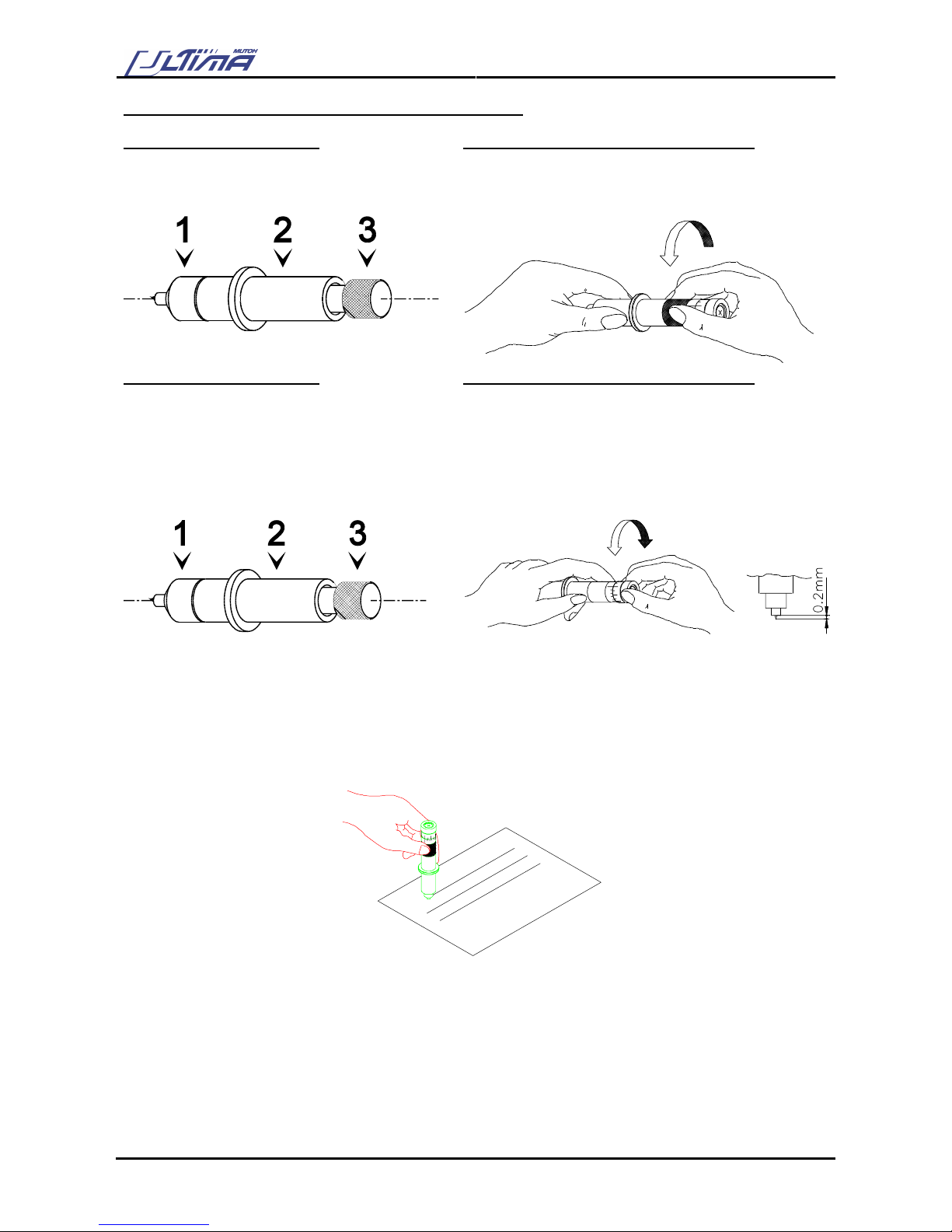
User’s Guide – Ultima cutting plotter
70 AP-75032, Rev 2.2, 20/04/07
TO ADJUST THE KNIFE DEPTH, PROCEED AS FOLLOWS:
STANDARD KNIFE HOLDER
OPTIONAL KNIFE HOLDER WITH NONIUS
Hold the body (2) in one hand and adjust the
depth by using the set screw (3).
Loosen the base part of the cutting knife. To do this,
take the base part in your left hand and twist the ring
slightly.
STANDARD KNIFE HOLDER
OPTIONAL KNIFE HOLDER WITH NONIUS
Turning the set screw (3) clockwise will make the
blade protrude out of the edge of the base part
(1). Turning the set screw (3) counterclockwise,
will retract the blade.
For a first test, turn out the blade until it protrudes
about 0.2mm (0.008”) out of the base part
Take the base part and the ring in your left hand and
twist the shaft until the knife point protrudes about 0.2
mm (0.008”) out of the edge of the base part.
Tighten the ring firmly against the base part. This will
prevent the cutting blade from coming loose during
cutting.
Make a manual test-cut on a small piece of media, of the same type that you will be using. Adjust the depth
until the top layer is cut completely and that you can see a slight scratch on the backing when peeling off.
At no times you should be able to see a scratch at the back side of the media.
Repeat steps 2 and 3 until the correct depth is obtained.

User’s Guide – Ultima cutting plotter
71 AP-75032, Rev 2.2, 20/04/07
FEATURES OF THE OPTIONAL KNIFEHOLDER
For some applications it might be convenient to be able to very accurately change the depth of the cutting
blade. For those applications, MUTOH can provide you with an optional knife holder, featuring a nonius
(vernier) with which it is possible to adjust the depth of the knife in increments of 0.01 millimeter (0.0004”)
The upper scale lines make it possible to change the knife depth over 0.05 mm (0.002”).
The lower scale (nonius) makes it possible to change the knife depth over 0.01 mm (0.0004”).
-0,05mm
+0,05mm
-0,01mm
+0,01mm
5.2. SETTING THE CUTTING PRESSURE / TEST SQUARES
Here, we merely want to point out that you have to try to cut your design with the lowest possible pressure
that gives no trouble to weed. Some cast media require only 20 grams to be cut completely through. In that
case there is no need to apply 100 grams of pressure. Too much pressure can cause a decrease of quality.
By pressing the [OFFSET] key you can change the offset of the knife:
¾ When you enter this menu you can input the offset or the base offset for cutting the calibration figures.
¾ When you press the [ENTER] key you get a dialog on the cutter that asks if you want to do a test cutting
(select 1 or 2) or not.
¾ When you perform a test cut, 10 reference pictures around the selected base offset are cut. You can
choose the best one by selecting one of the pictures with the laser pointer and the [UP] and [DOWN] key.

User’s Guide – Ultima cutting plotter
72 AP-75032, Rev 2.2, 20/04/07
5.3. OFFSET PRINCIPLE
One of the most important factors to obtain good quality, but unfortunately also one of the factors that is
easily forgotten, is the offset.
1: Cutter blade
2: Theoretical Offset
As you can see in the above figure, the knife offset (2) is the distance between the knife center and the knife
tip.
Accurate measurement of the OFFSET to be used is very difficult and requires specialized equipment. You
should therefore adjust the offset (2) by checking real cutting results on the media you will use. MUTOH
helps you doing this by way of a semi-automatic offset adjustment routine, which has been integrated into
your cutter.
5.4. OFFSET EFFECT
The selected Offset value is LARGER than the
optimum knife offset.
The selected Offset value is SMALLER than the
optimum knife offset.
In this case, a square corner will be cut as follows : In this case, a square corner will be cut as follows :
The cutting direction is indicated by the arrow. The
corners are not well formed.
The cutter cuts too far in the angular points.
The cutting direction is indicated by the arrow. The
corners are not well formed. The cutter did not cut
far enough in the angular points.
1
2
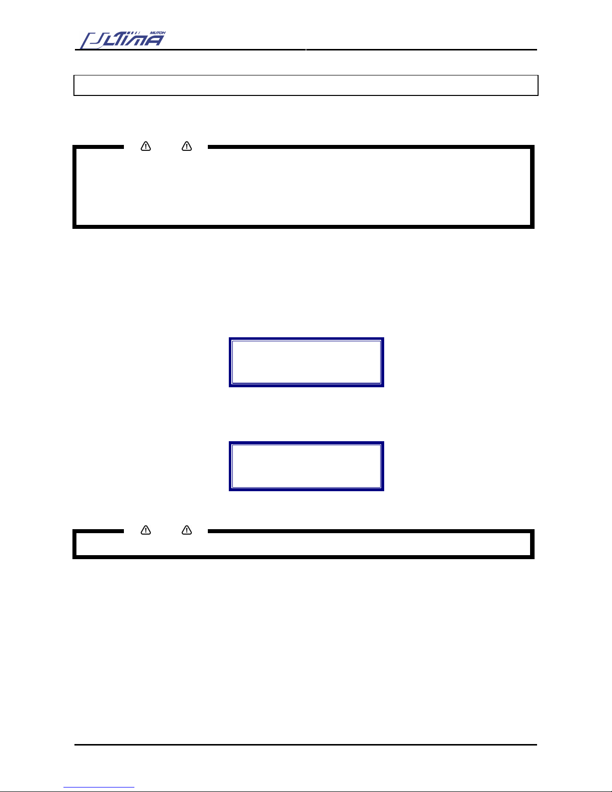
User’s Guide – Ultima cutting plotter
73 AP-75032, Rev 2.2, 20/04/07
5.5. OFFSET ADJUSTMENT PROCEDURE
In the Ultima you have 2 tools (drag knife and pen) with its own velocity, force, acceleration, offset (only drag
knife) settings. Each user preset holds the settings for these 2 tools.
Notes
1) Inaccurate offset setting may cause :
¾ POOR cutting quality.
¾ Difficult weeding.
2) In case the offset adjustment routine is aborted, the cutter will continue working with the value prior to
launching the adjustment routine.
To perform an offset, please follow the instructions mentioned below.
Step 1 : Install a knife in the tool head. Please do not forget to select knife in the menu.
Step 2 : Install a sheet of media.
Step 3 : Press the [OFFSET] key. The display will show the following message.
Offset
Actual : 0,50
New : 0,50
Calibration base
Step 4 : By pressing the [UP] or [DOWN] key select a value.
Step 5 : Press the [ENTER] key to confirm. The display will show the following message.
Test offset:
Cancel = no test
Up = test1
Down = test2
Step 6 : By pressing the [UP] or [DOWN] key select the “test1” or “test2”
Notes
Press the [CANCEL] key in case you do not want to perform an offset.

User’s Guide – Ultima cutting plotter
74 AP-75032, Rev 2.2, 20/04/07
You have selected “TEST1”
Step 7 : After pressing the [UP] key, the cutter will cut the offset “TEST1”.
Following pattern is cut.
0.45 0.46 0.47 0.48 0.49 0.50 0.51 0.52 0.53 0.54
The display will show the following message:
Offset : 0.50
Enter = select
Up = Up
Down = Down
Step 8 : Use the [ARROW] keys to forward the media. Check the patterns and determine which of them
gives best quality. Especially look for good quality of the corners, closure of the circles and easy
weeding.
Step 9 : Use the [UP] or [DOWN] key to select the correct Offset value. The LED will light up the chosen
value.
Step 10 : Press the [ENTER] key to confirm.
You have selected “TEST2”
Step 7 : After pressing the [DOWN] key, the cutter will cut the offset “TEST2”.
Following pattern is cut.
0.55 0.54 0.53 0.52 0.51 0.50 0.49 0.48 0.47 0.46
The display will show the following message:
Offset : 0.50
Enter = select
Up = Up
Down = Down
Step 8 : Use the [ARROW] keys to forward the media. Check the patterns and determine which of them
gives best quality. Especially look for good quality of the corners and easy weeding.
Step 9 : Use the [UP] or [DOWN] key to select the correct Offset value. The LED will light up the chosen
value.
Step 10 : Press the [ENTER] key to confirm.

User’s Guide – Ultima cutting plotter
75 AP-75032, Rev 2.2, 20/04/07
5.6. PERFORMING A TEST CUT
In order to enable the user to check if the cutter is fully functional, without needing a computer, Mutoh
Europe has integrated thirteen demo test cuts into the Ultima cutters. The demo cuts are accessible by
pressing the [TEST] key.
5.6.1.
Cut Test → SC-850 or SC-1400
To perform the ‘SC-850’ procedure, please follow the instructions mentioned below.
Notes
Dependent on which machine type you have, the program will select sc-850 or sc-1400.
Step 1 : Load some vinyl (cut-sheet or roll) into the cutter.
Step 2 : Make sure that a knife tool is selected.
Step 3 : Make sure that a knife with well adjusted depth is mounted into the tool head.
Step 4 : If you have not yet performed the offset adjustment routine for the current knife and/or vinyl, first
perform this routine in order to obtain perfect quality.
Step 5 : Press the [TEST] key. The display will show the following message.
Cut Test:
Quality check
→ SC-850 or SC-1400
Choose testfile
Step 6 : By pressing the [UP] or [DOWN] key select “SC-850 or SC-1400”.
Cut Test:
SC-850 or SC-1400
→ Cut test
Choose testfile
Step 7 : Press the [ENTER] key to confirm.
Notes
If you do not want to perform a test, press the [EXIT] key.
Step 8 : The Ultima will cut a picture. Check the patterns. Especially look for good quality of the corners
and easy weeding. If this is not the case readjust the Ultima cutting plotter.

User’s Guide – Ultima cutting plotter
76 AP-75032, Rev 2.2, 20/04/07
5.6.2. Quality check
Step 1 : Load some vinyl (cut-sheet or roll) into the cutter.
Step 2 : Make sure that a knife tool is selected.
Step 3 : Make sure that a knife with well adjusted depth is mounted into the tool head.
Step 4 : If you have not yet performed the offset adjustment routine for the current knife and/or vinyl, first
perform this routine in order to obtain perfect quality.
Step 5 : Press the [TEST] key. The display will show the following message.
Testplot :
Quality check
→ SC-850 or SC-1400
Choose testfile
Step 6 : By pressing the [UP] or [DOWN] key select “Quality check”.
Step 7 : Press the [ENTER] key to confirm.
Notes
If you do not want to perform the test, press the [EXIT] key.
Step 8 : The Ultima will cut a picture. Check the patterns. Especially look for good quality of the corners
and easy weeding. If this is not the case readjust the Ultima cutting plotter.
5.6.3. Knife offset → Test
Step 1 : Load some vinyl (cut-sheet or roll) into the cutter.
Step 2 : Make sure that a knife tool is selected.
Step 3 : Make sure that a knife with well adjusted depth is mounted into the tool head.
Step 4 : If you have not yet performed the offset adjustment routine for the current knife and/or vinyl, first
perform this routine in order to obtain perfect quality.
Step 5 : Press the [TEST] key. The display will show the following message.
Testplot :
Quality check
→ SC-850 or SC-1400
Choose testfile
Step 6 : By pressing the [UP] or [DOWN] key select ‘Knife offset → test’. The display on the operation
panel will show the following message.
Testplot :
Knife Offset
→ test
Choose testfile

User’s Guide – Ultima cutting plotter
77 AP-75032, Rev 2.2, 20/04/07
Step 7 : Press the [ENTER] key to confirm.
Notes
If you do not want to perform the test, press the [EXIT] key.
Step 8 : The Ultima will cut following pattern.
5.6.4. Settings Plot
To plot the settings, please follow the instructions mentioned below.
Step 1 : Install a pen.
Step 2 : Press the [TOOL] key and select ‘pen’.
Step 3 : Install an A3-format paper (portrait)
Step 4 : Press the [TEST] key. The display will show the following message.
Testplot :
Quality check
→ SC-850 or SC-1400
Choose testfile
Step 5 : By pressing the [UP] or [DOWN] key select ‘Settings → plot’. The display on the operation panel
will show the following message.
Testplot :
Settings
→ Plot
Choose testfile
Step 6 : The Ultima cutting plotter will plot the actual settings.

User’s Guide – Ultima cutting plotter
78 AP-75032, Rev 2.2, 20/04/07
5.6.5. EPOS Align tune (Manual)
The manual calibration can be done with knife or with pen. Depending of the installed tool a test plot will be
drawn/cut.
5.6.3.1. Manual calibration with knife
To calibrate the E-pos system using the ‘manual calibration’ with knife, please follow the instructions
mentioned below.
Step 1 : Install a knife.
Step 2 : Press the [TOOL] key and select ‘knife’.
Step 3 : Install a black vinyl.
Step 4 : First set the ORIGIN in the middle of the media.
¾ Press the [Origin] key.
¾ Use the [ARROW] keys to position the tool head in the middle of the media.
¾ Press the [ENTER] key to confirm.
Step 5 : Press the [TEST] key. The display will show the following message.
Testplot :
Quality check
→ SC-850 or SC-1400
Choose testfile
Step 6 : By pressing the [UP] or [DOWN] key select ‘EPOS align tune --> manual’. The Display on the
Operation Panel will show the following message.
Testplot :
EPOS align tune
→ manual
Choose testfile
Step 7 : Press the [ENTER] key. The Ultima cutting plotter will start cutting two square boxes. After
drawing following message will appear.
Measure box is
cut please
weed out and
press a button
Step 8 : Peel off the boxes cut by the Ultima cutting plotter.
Step 9 : Press the [ENTER] key.
Step 10 : The Ultima cutting plotter will move the laser to the point where both squares touch. Following
message will appear.
* Epos Calibration. *
Please move
laser pointer to
cross and enter

User’s Guide – Ultima cutting plotter
79 AP-75032, Rev 2.2, 20/04/07
Step 11 : If necessary, use the [ARROW] keys to position the laser exactly onto the point where both
squares touch. Do not keep the [ARROW] keys pressed, they only causes one movement.
Step 12 : Press the [ENTER] key to confirm the position of the laser. The distance between laser and knife
is calculated and stored.
Step 13 : Calibration of the E-pos system with the ‘manual calibration’ method is done.
5.6.3.2. Manual calibration with Pen
To calibrate the E-pos system using the ‘manual calibration’ with pen, please follow the instructions
mentioned below.
Step 1 : Install a pen.
Step 2 : Press the [TOOL] key and select ‘pen’.
Step 3 : Install an A4-format paper.
Step 4 : First set the ORIGIN in the middle of the media.
¾ Press the [Origin] key.
¾ Use the [ARROW] keys to position the tool head in the middle of the media.
¾ Press the [ENTER] key to confirm.
Step 5 : Press the [TEST] key. The display will show the following message.
Testplot :
Quality check
→ SC-850 or SC-1400
Choose testfile
Step 6 : By pressing the [UP] or [DOWN] key select ‘EPOS align tune --> manual’. The Display on the
Operation Panel will show the following message.
Testplot :
EPOS align tune
→ manual
Choose testfile
Step 7 : Press the [ENTER] key. The Ultima cutting plotter will start drawing a cross.
Step 8 : The Ultima cutting plotter will move the laser to the point where both lines intersect. Following
message will appear.
* Epos Calibrate. *
Please move
laser pointer to
cross and enter
Step 9 : If necessary, use the [ARROW] keys to position the laser exactly onto the point where both lines
intersect. Do not keep the [ARROW] keys pressed, pressing the keys only causes one
movement.
Step 10 : Press the [ENTER] key to confirm the position of the laser. The distance between laser and knife
is calculated and stored.
Step 11 : Calibration of the E-pos system with the ‘manual calibration’ method is done.

User’s Guide – Ultima cutting plotter
80 AP-75032, Rev 2.2, 20/04/07
5.6.6. EPOS Align tune (Automatic)
To calibrate the E-pos system using the ‘Automatic calibration’, please follow the instructions mentioned
below.
Step 1 : Install a knife.
Step 2 : Press the [TOOL] key and select ‘knife’.
Step 3 : Install a black vinyl.
Step 4 : Press the [TEST] key. The display will show the following message.
Testplot :
Quality check
→ SC-850 or SC-1400
Choose testfile
Step 5 : By pressing the [UP] or [DOWN] key select ‘EPOS align tune --> automatic. The Display on the
Operation Panel will show the following message.
Testplot :
EPOS align tune
→ automatic
Choose testfile
Step 6 : Press the [ENTER] key. The Ultima cutting plotter will cut a square. After cutting following
message will appear.
Measure box is
cut please
weed out and
press a button
Step 7 : Peel of the box cut by the Ultima cutting plotter.
Step 8 : Press the [ENTER] key.
Step 9 : The laser of the Ultima cutting plotter will measure the box. The distance between laser and
knife is calculated and stored.
Step 10 : Calibration of the E-pos system with the ‘automatic calibration’ method is done. Following
message will appear.
EPOS
Calibration
done
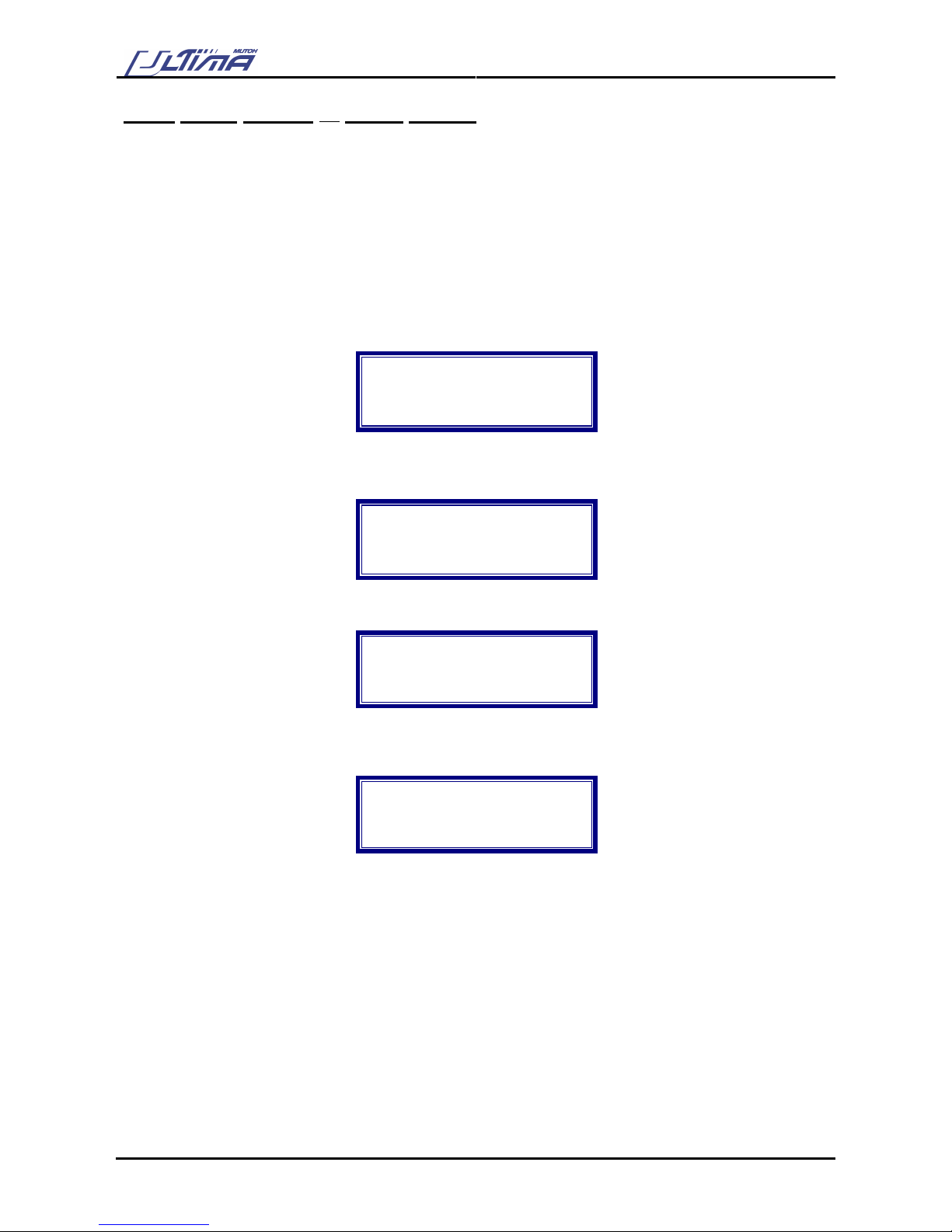
User’s Guide – Ultima cutting plotter
81 AP-75032, Rev 2.2, 20/04/07
5.6.7. EPOS system → check sensor
When you want to print on a grey vinyl for example, it is possible that the Ultima will not detect the frame
(bounding box) on the vinyl. That’s the main reason of the “Check sensor” menu. When you put the vinyl in
the Ultima, and you do a sensor check, and the ACD value is black, it will be impossible to do a contour cut
on that vinyl. When the ACD value displays white, you will not have any problems.
You can also use this menu to check if the Photodiode still works. Just draw a black box on a white paper,
and check if the Photodiode displays the right colour.
Step 1 : Power ON the Ultima cutting plotter.
Step 2 : Press the [TEST] key. The display will show the following message.
Testplot :
Quality check
→ SC-850 or SC-1400
Choose testfile
Step 3 : By pressing the [UP] or [DOWN] key select ‘EPOS system --> check sensor’. The Display on the
Operation Panel will show the following message.
Testplot :
EPOS system
→ check sensor
Choose testfile
Step 4 : Press the [ENTER] key. The Display on the Operation Panel will show the following message.
*Photodiode*
ADC value:
BLACK
Change the value
Step 5 : When you put a white A4-format paper (or one with white and black boxes on) under the sensor,
the display must show following message. Otherwise the sensor is broken.
*Photodiode*
ADC value:
WHITE
Change the value

User’s Guide – Ultima cutting plotter
82 AP-75032, Rev 2.2, 20/04/07
5.6.8. Test sheet verify epos alignment
5.6.8.1 EPOS Alignment → test plot
Verify Automatic EPOS Alignment workflow (From FW V2.00 onwards)
To verify the EPOS alignment, please follow the instructions below.
Step 1 : Power ON the Ultima cutting plotter and install a pen.
Step 2 : Press the [TOOL] key and select ‘pen’.
Step 3 : Make sure levers are up.
Step 4 : Set speed = 30 cm/s, Force = 60 gr
Step 5 : Load media (AP-77010), delivered with the Ultima Cutting Plotter. (with the black arrow in the
upper right corner)
Step 6 : Levers down. Make sure the pressure rollers are located outside your frame
Step 7 : Press the [TEST] key. The display will show the following message.
Testplot :
Quality check
→ SC-850 or SC-1400
Choose testfile
Step 8 : By pressing the [UP] or [DOWN] key select ‘EPOS alignment --> test plot’. The Display on the
Operation Panel will show the following message.
Testplot :
EPOS alignment
→ test plot
Choose testfile
Step 9 : Press the [ENTER] key. The laser of the Ultima cutting plotter will measure the box and will start
(re)drawing the image file.
Step 10 : Verify positioning of contour cutting.
To verify bar code reading, please follow the instructions mentioned below.
Notes
In the box of the Ultima Cutting Plotter, there’s a paper (Test sheet verify epos
alignment) delivered with the pattern on.
You can find the procedure also on the sheet.
Perform this test before you start contour cutting.

User’s Guide – Ultima cutting plotter
83 AP-75032, Rev 2.2, 20/04/07
6. PLOTTER MAINTENANCE &
TROUBLESHOOTING
In this chapter, you will learn:
How to keep your cutter in good shape and prevent problems by regularly performing some easy, daily
maintenance.
How to pinpoint and check out problems that might occur.
6.1. CLEANING & DAILY MAINTENANCE
Your cutting plotter, knives and pens will work better and last longer if you keep them clean and perform a
few simple daily maintenance tasks.
Notes
Before performing cleaning and daily maintenance, please power OFF the unit and remove the power
cable.
6.1.1. Cleaning the grid rolls
The figure below shows you this part of the plotter that might require your attention.
The pressure rollers (2) press the vinyl firmly against
the friction drive rolls (5). For this reason it is
possible that, after some time, the friction drive rolls
(5) become clogged with accumulated residue from
cutting media. This can cause slippage of the
material, resulting in inaccurate cuts or incorrect vinyl
transport.
Therefore it is a good habit to clean the drive rolls
regularly.
To do this you can use a brush and rotate the rolls
manually to make sure that they are thoroughly
cleaned.

User’s Guide – Ultima cutting plotter
84 AP-75032, Rev 2.2, 20/04/07
6.1.2. Cleaning the cutter blade
Use following procedure to remove small vinyl particles in the base part of the cutting blade holder.
STANDARD KNIFE HOLDER
KNIFE HOLDER WITH NONIUS
Step 1
Take the body (2) into one hand and unscrew the
base part (1).
Step 1
Take the ring in your hand and remove the base part.
Step 2
Blow away the vinyl particles accumulated in the
top of the base part
Step 2
Blow away the vinyl particles accumulated in the top
of the base part
Step 3
Remove the spring from the cutting blade and
remove any residual material from the blade tip
Step 3
Remove any residual material from the blade tip
Step 4
Place the spring back over the cutting blade and
tightly screw the base part on the holder.
Step 4
Place the base part back on the holder and twist it
tightly.
6.1.3. Cleaning the cutting plotter
Use a soft cloth to clean paper dust and particles off the platen, the grid cover the cutting mat and the
carriage cover.
Use a cotton swab to clean the media sensors and laser.

User’s Guide – Ultima cutting plotter
85 AP-75032, Rev 2.2, 20/04/07
6.2. WEAR & TEAR
Although all materials used for your cutter have been chosen to ensure good durability, it will be necessary,
in order to maintain high quality output, to replace some parts, which are liable to wear and tear.
Notes
Before performing “wear and tear”, please power OFF the unit and remove the power cable.
6.2.1. Replacing the cutting mat
To replace the cutting mat, proceed as follows:
Step 1 : First of all, remove the worn cutting mat by pulling it out, together with the underlying strip of vinyl.
Step 2 : Cut a strip of vinyl ( Width : 8 mm (0,3”) / Length : depending on the size of your cutter.) Stick this
strip into the cutting groove.
Step 3 : Complete this procedure by sticking the new cutting mat into the cutting groove.
1) cutting mat / 2) Strip of vinyl
1
2

User’s Guide – Ultima cutting plotter
86 AP-75032, Rev 2.2, 20/04/07
6.2.2. Replacing the knife blade
To replace a blade, please proceed as follows:
STANDARD KNIFE HOLDER
KNIFE HOLDER WITH NONIUS
Step 1: Hold the body (2) into one hand and
unscrew the base part (1)
Step 1: Take the body into one hand and remove the
base part
Step 2: Remove the spring (3) and the cutting
blade (4).
Step 2: Pull the old blade out of the holder and insert
a new one
Step 3: Slide the spring over the new cutting blade Step 3: Place the base part on top of the holder
assembly and twist it tightly.
Step 4: Place the new blade with its spring into the
base part and screw the whole assembly onto the
body.

User’s Guide – Ultima cutting plotter
87 AP-75032, Rev 2.2, 20/04/07
6.2.3. Replacing the auto sheet-off knife
When you frequently use the auto-sheet-off utility, it is a good practice to regularly clean the knife and to
replace it when it starts to wear.
To replace the auto sheet-off knife, please follow the instructions mentioned below.
Step 1 : Power OFF the unit and remove the power cable.
Step 2 : Remove the 2 screws fixing the head cover.
Step 3 : Remove the cutter cap. Please do not lose the spring.
1 = cutter cap
Step 4 : Remove the sheet-off knife.
Step 5 : Clean the sheet-off knife, removing any material residues that might be clogged to the blade. In
case the blade is worn, reinstall a new knife.
Step 6 : Place the (new) knife into the auto sheet-off assembly. Make sure the knife is correctly oriented.
Step 7 : Reinstall the cutter cap onto the auto sheet-off knife.
Step 8 : Reinstall the head cover.

User’s Guide – Ultima cutting plotter
88 AP-75032, Rev 2.2, 20/04/07
6.3. CLEAN SENSOR AND E-POS LASER.
Ultima’s sensors and E-pos laser will work better and last longer if you keep them clean and perform a few
simple daily maintenance tasks.
Use a cotton swab to clean the media sensors and E-pos laser.
6.3.1. Testing E-pos Laser
Please follow the instructions below to check if the Laser of the E-pos system is still working.
Step 1 : Press the [ORIGIN] key.
Step 2 : The LED should start lighting.
Step 3 : Press the [CANCEL] key to exit the setting.
Notes
Please do not look straight into the light.
Notes
In case the laser of the E-pos system is not working, please contact your local Mutoh dealer.

User’s Guide – Ultima cutting plotter
89 AP-75032, Rev 2.2, 20/04/07
6.4. TROUBLESHOOTING
In this section you will find a summary of problems that might occur during day-to-day use of your cutter and
some hints how to determine the cause of the problem.
1. Power switch is turned ON, but the cutter does not operate.
¾ Is the power cable connected to the cutter?
¾ Is the cutter connected to a power outlet with the specified voltage?
2. Media is loaded, but the cutter does not operate.
¾ Is the media hold lever lowered?
¾ Is the media properly loaded?
¾ Are the paper sensors clean?
3. Data is being sent from the computer, but the cutter does not react.
¾ Is there a proper interface cable connected?
¾ Do the interface conditions on the host computer match those set on the cutter?
4. Data is sent from the computer but errors occur on the cutter’s side.
¾ Are the output settings correct on the host computer and in the cutting software?
¾ Do the interface conditions on the host computer match those set on the cutter?
¾ Does the command mode on the host computer match the command mode on the cutter?
5. Some parts of the design are not well cut.
¾ Check whether the knife tip is not clogged with material residues.
¾ Examine the knife blade with a magnifier to see if the tip is not damaged or broken.
¾ Perform the offset adjustment routine to check cutting quality.
¾ Perform the internal test cut and check its quality.

User’s Guide – Ultima cutting plotter
90 AP-75032, Rev 2.2, 20/04/07
6.5. CHECKING THE COMMUNICATION SETTINGS
Communication problems are the most frequent errors, which occur. Therefore we have included a step-
by-step procedure to check out your configuration’s communication settings and assure that your cutter is
working fine.
Step 1 : Boot-up your computer.
Step 2 : Switch on the cutter.
Step 3 : After the initialization routine is finished, install a knife or pen in the head, select the proper tool
and load a sheet of media, which is at least 12 x 12 centimeters.
Step 4 : Make sure the cutter shuffles the media and verify that the cutter is Ready.
Step 5 : On the host computer go to the DOS-prompt (c:\> ).
If another environment ( for example : windows ) is automatically loaded after booting up, quit this
application before continuing.
Step 6 : Check with which of the host computer’s communication ports your cutter is connected ( COM1,
COM2, LPT1, … ) to.
Step 7 : If your computer and cutter are linked with a serial interface ( COM1 or COM2 ), type following
command.
MODE COM1: 96,n,8,1,p then press <ENTER>
or
MODE COM2: 96,n,8,1,p then press <ENTER>
Notes
The command above will change your computer’s serial communication settings to match the cutter’s
factory default communication settings.
These settings are : 9600 BAUD, NONE parity, 8 data-bits, 1 stop bit.
Step 8 : Using any text editor, create a file called TEST.PLT with the following contents:
( To start the DOS editor you can type : edit TEST.PLT <ENTER> )
IN;
SP1;
PA0,0;
PD0,4000,4000,4000,4000,0,0,0;
PU2000,2000;
CI2000;
SP0;
Step 9 : Save this file onto a floppy or on your hard-disk.
Step 10 : Exit the text editor and return to the DOS-prompt.
Step 11 : Make sure you are in the directory where the file is located.
Step 12 : Type following command :
copy TEST.PLT COM1 ( If your cutter is connected to COM1 )
copy TEST.PLT COM2 ( If your cutter is connected to COM2 )
copy TEST.PLT LPT1 ( If your cutter is connected with the parallel printer port )
Step 13 : Then press <ENTER>.
The file you have created will now be sent to the cutter, causing it to cut/draw a square of 10 by
10 cm. And a circle with a radius of 5 cm.

User’s Guide – Ultima cutting plotter
91 AP-75032, Rev 2.2, 20/04/07
6.6. ERROR MESSAGES
6.6.1. Recoverable system errors
In this section you will find a summary of problems that might occur during day-to-day use of your cutter and
some hints how to determine the cause of the problem.
1. Power switch is turned ON, but the cutter does not operate.
¾ Is the power cable connected to the cutter?
¾ Is the cutter connected to a power outlet with the specified voltage?
2. Media is loaded, but the cutter does not operate.
¾ Is the media hold lever lowered?
¾ Is the media properly loaded?
¾ Are the paper sensors clean?
3. Data is being sent from the computer, but the cutter does not react.
¾ Is there a proper interface cable connected?
¾ Do the interface conditions on the host computer match those set on the cutter?
4. Data is sent from the computer but errors occur on the cutter’s side.
¾ Are the output settings correct on the host computer and in the cutting software?
¾ Do the interface conditions on the host computer match those set on the cutter?
¾ Does the command mode on the host computer match the command mode on the cutter?
5. Some parts of the design are not well cut.
¾ Check whether the knife tip is not clogged with material residues.
¾ Examine the knife blade with a magnifier to see if the tip is not damaged or broken.
¾ Perform the offset adjustment routine to check cutting quality.
¾ Perform the internal test cut and check its quality.

User’s Guide – Ultima cutting plotter
92 AP-75032, Rev 2.2, 20/04/07
6.6.2. Unrecoverable system errors
Unrecoverable errors may be caused by some part of the cutting plotter, which is malfunctioning. In case
of an unrecoverable error, most of the time the cutter will be completely blocked and all the LEDs will be
flashing. The error id, number and description will appear on the keyboard display, and will be cleared when
entering a key.
IDFE_NOYENCODER 1000 "No Y encoder, check connectors or call service"
IDFE_YPOSENCTURN 1001 "Y+ encoder turn, check connector or call service"
IDFE_YNEGENCTURN 1002 "Y- encoder turn, check connectors or call service"
IDFE_YXSWAPPED 1004 "YX are swapped, check connectors or call service"
IDFE_NOXENCODER 1005 "No X encoder, check connectors or call service"
IDFE_XPOSENCTURN 1006 "X+ encoder turn, check connectors or call service"
IDFE_XNEGENCTURN 1007 "X- encoder turn, check connectors or call service"
IDFE_XYSWAPPED 1008 "XY are swapped, check connectors or call service"
IDFE_YPOSERROR 1009 "Y position error, PWM switched off as a safety"
IDFE_XPOSERROR 1010 "X position error, PWM switched off as a safety"
IDFE_ZPOSERROR 1011 "Z position error, PWM switched off as a safety"
IDFE_DRAMERROR0 1012 "MEMORY size allocation error"
IDFE_DRAMERROR1 1013 "MEMORY allocation lower limit error"
IDFE_DRAMERROR2 1014 "MEMORY allocation upper limit error"
IDFE_GENYENCODER 1020 "General Y encoder failure, PWM switched off"
IDFE_GENXENCODER 1030 "General X encoder failure, PWM switched off"
IDFE_SERIALOFW 1040 "Serial Buffer Overflow Error"
IDFE_VECTOROFW 1041 "Vector Buffer Overflow Error"
IDFE_SERVOOFW 1042 "Servo Buffer Overflow Error"
IDFE_NOZENCODER 1045 "No Z encoder, check connectors or call service"
IDFE_ZPOSENCTURN 1046 "Z+ encoder turn, check connectors or call service"
IDFE_ZNEGENCTURN 1047 "Z- encoder turn, check connectors or call service"
IDFE_GENZENCODER 1048 "General Z encoder failure, PWM switched off"
IDFE_RAMCARDAAAA 1200 "RamCard Error while writing 'AAAA' code"
IDFE_RAMCARD5555 1201 "RamCard Error while writing '5555' code"
IDFE_UNDEFCARD 1205 "Undefined card inserted"
IDFE_UNDEFCARDWP 1206 "Undefined card inserted and write protected"
IDFE_CORRUPTUCCA 1300 "Corrupt 'UCCA' code, Flash incorrectly loaded"
IDFE_CORRUPTFCCA 1301 "Corrupt 'FCCA' code, Flash incorrectly loaded"
IDFE_MBUS_SWMBSR_BUSY_TIMEOUT 6000 "MBUS SW BUSY timeout"
IDFE_MBUS_SWMBSR_RECV_TIMEOUT 6001 "MBUS SW RECEIVE timeout"
IDFE_MBUS_HWMBSR_MBB_TIMEOUT 6002 "MBUS HW MBB timeout"
IDFE_MBUS_HWMBSR_MIF_TIMEOUT 6003 "MBUS HW MIF timeout"
IDFE_MBUS_CMD_STOP 6004 "MBUS Stop command failed"
IDFE_MBUS_HWMBSR_MAL_ERROR 6005 "MBUS HW MAL arbitration lost error"
IDFE_MBUS_HWMBSR_ADR_RXAK_ERROR 6006 "MBUS HW RXAK no ack from slave in adr cycle"
IDFE_MBUS_HWMBSR_DATA_RXAK_ERROR 6007 "MBUS HW RXAK no ack from slave in data cycle"
IDFE_MBUS_HWMBSR_INT_MAL_ERROR 6008 "MBUS HW MAL INT arbitration losterror"
IDFE_MBUS_HWMBSR_INT_ADR_RXAK_ERROR 6009 "MBUS HW RXAK INTno ack from slv in adr cycle"
IDFE_MBUS_CMD_PIOREAD 6010 "MBUS PIO Read (POLL) command failed"
IDFE_MBUS_CMD_ADCREAD 6011 "MBUS ADC Read (POLL) command failed"
IDFE_MBUS_CMD_PIOWRITE 6012 "MBUS Piowrite command failed"
IDFE_MBUS_CMD_PIOREADI 6013 "MBUS PIO Read (INT) command failed"
IDFE_MBUS_CMD_ADCREADI 6014 "MBUS ADC Read (INT) command failed"
IDFE_MBUS_CMD_SETDATA 6015 "MBUS SetData command failed"
IDFE_MBUS_CMD_GETDATA 6016 "MBUS GetData command failed"
IDFE_MBUS_CMD_PIOSET 6017 "MBUS PIOSet command failed"
IDFE_MBUS_CMD_READ 6018 "MBUS Read command failed"

User’s Guide – Ultima cutting plotter
93 AP-75032, Rev 2.2, 20/04/07
IDFE_MBUSGETDATA_SEARCHSENSOR 6019 "MBUS GETDATA IN SEARCHSENSOR"
IDFE_MBUSSTOP_SEARCHSENSOR 6020 "MBUSSTOP IN SEARCHSENSOR"
IDFE_MBUSSTOP_SEARCHSENSOR1 6021 "MBUSSTOP IN SEARCHSENSOR1"
IDFE_MBUSSTOP_SEARCHSENSOR2 6022 "MBUSSTOP IN SEARCHSENSOR2"
IDFE_MBUS_CMD_SETKNIFE 6023 "PROBLEM IN SETKNIFE"
IDFE_MBUS_CMD_SETLASER 6024 "PROBLEM IN SETLASER"
IDFE_SFWT_CTF 6070 "SFWT delay_ctf problem"
IDFE_SFWT_MATCHINTU 6071 "SFWT match_intu problem"
IDFE_SFWT_DELAY 6072 "SFWT delay problem"
IDFE_MOVEABSMC 6080 "Moveabsmc problem"
IDFE_OPOS_MBUSREAD 6090 "EPOS Mbus read blocks"
IDFE_OPOS_MBUSSTOP 6091 "EPOS Mbus read blocks"
IDFE_OPOS_CALCPENTOLED_SEARCHEDGE 6092 "EPOS calc pen toled search edge blocks"
IDFE_OPOS_AUTOCALIBRATE_SEARCHEDGE 6093 "EPOS auto calibrate search edge blocks"
IDFE_OPOS_AUTOCALIBRATE_CALIBRATE1 6094 "EPOS calibrate get data blocks"
IDFE_OPOS_AUTOCALIBRATE_CALIBRATE2 6095 "CALIBRATE PROBLEM IN AUTOCALIBRATE 2"
IDFE_OPOS_CALIB_GETDATA 6096 "EPOS calibrate get data blocks"
IDFE_OPOS_CALIBRPENTOLED 6097 "EPOS calibrate pen to led blocks"
IDFE_BUMP_WRONG_MACHINE_WIDTH 6100 "BUMP PROBLEM MACHINE WIDTH"
IDFE_SHUFFLE_WRONG_MACHINE_WIDTH 6101 "SHUFFLE PROBLEM MACHINE WIDTH"
IDFE_SHUFFLE1 6105 "SHUFFLE PROBLEM1"
IDFE_SHUFFLE2 6106 "SHUFFLE PROBLEM2"
IDFE_SHUFFLE3 6107 "SHUFFLE PROBLEM3"
IDFE_SHUFFLE4 6108 "SHUFFLE PROBLEM4"
IDFE_SHUFFLE5 6109 "SHUFFLE PROBLEM5"
IDFE_DRAM_OVERRUN 6111 "DRAM overrun error"
IDFE_SRAM_OVERRUN 6112 "SRAM overrun error"
6.6.3. Communication errors
Communication errors are caused by a problem in the communication between the cutter and the host
computer. They can be caused by errors related to the communication conditions, errors due to a defective
handshake or command format errors in the ESCAPE sequences.
KEYB_COMM_CHECKSUM : KEYB communication checksum problem
UART1_COMM_ERROR : UART1 communication error
UART2_COMM_ERROR : UART2 communication error
UART2_SENDTOKEYB_ERROR : UART2 send to keyb problem
6.6.4. Language errors
Language errors occur when command data entered from the host computer does not match the data
format of the command mode currently activated on the cutter’s side. The error can be caused by a
difference in command type or by a syntax error.
PGTOOSHORT : PG error : Media too short to perform a 'PG;'.
PGM0TOOSHORT : PG Mode 0 Error : Media too short to perform a 'PG;'.
PGM1TOOSHORT : PG Mode 1 Error : Media too short to perform a 'PG;'.
PGM2TOOSHORT : PG Mode 2 Error : Media too short to perform a 'PG;'.
DRAWERROR00 : Out of limit error, vector has been clipped.
Each HPGL command has its own error code with a message

User’s Guide – Ultima cutting plotter
94 AP-75032, Rev 2.2, 20/04/07
User’s Guide – Ultima cutting plotter
95 AP-75032, Rev 2.2, 20/04/07
7. ULTIMA CUTTING PLOTTERS -
MEDIA COMPATIBILITY & DIMENSIONS
7.1. ULTIMA CUTTING PLOTTERS: MEDIA COMPATIBILITY
Ultima 850
¾ Stand Model
¾ Maximum Media width:850 Roll and Cut-Sheet
¾ Maximum cutting width : 630 mm
Ultima 1400
¾ Stand Model
¾ Maximum Media width:1400 Roll and Cut-Sheet
¾ Maximum cutting width : 1200 mm
7.2. PHYSICAL DIMENSIONS ULTIMA
Ultima 850 Ultima 1400
Length 1205 1775
Width 670 670
Height 1175 1175
Weight 35 kg 45 kg

User’s Guide – Ultima cutting plotter
96 AP-75032, Rev 2.2, 20/04/07
 Loading...