

Musical Fidelity HTP Owners manual

HTP
Home Theatre Processor
INSTRUCTIONS FOR USE
Thank you for purchasing the Musical Fidelity
HTP Home Theatre Processor.
The HTP is an audio and video (AV) processor that
decodes Dolby Digital*, Dolby Pro Logic*
and DTS Digital SurroundTM.
It will accept S-Video and composite video signals.
It supports PAL and NTSC TV systems.
It has been designed to operate with all
Musical Fidelity Power amplifiers especially
the HT600, 5 channel power amp.
Used properly and carefully, it should give you many
years of outstanding musical reproduction.
Aesthetically, the HTP is a perfect match for the
HT600 power amplifier, A3 CD player and the A3 Tuner.
Dust regularly with a soft duster or soft brush but be
careful when using cleaning or polishing agents - they may
harm the surface finish.
Manufactured under license from Dolby Laboratories.
"Dolby", "Pro Logic" and the double-D symbol are trademarks of Dolby Laboratories.
Confidential unpublished works. ©1992-1997 Dolby Laboratories. All rights reserved.
"DTS" and "DTS Digital Surround" are registered trademarks of Digital Theater Systems, Inc.
issue 2/11.07.2000
HTP Home Theatre Processor Instructions for Use. Page 1 of 28

· Introduction · · · · · · · · · · · · · · · · · · · · · · · · · 3
· Safety Information · · · · · · · · · · · · · · · · · · · · 4
· Installation precautions and user information 5
· Front panel identification · · · · · · · · · · · · · · · 6
· Back panel identification · · · · · · · · · · · · · · · 6
· Remote control identification · · · · · · · · · · · 7
· Audio connections · · · · · · · · · · · · · · · · · · · · 8
· Video connections · · · · · · · · · · · · · · · · · · · · 9
· Trigger connections · · · · · · · · · · · · · · · · · · · 10
· Useful information · · · · · · · · · · · · · · · · · · · · 11
· Basic operation · · · · · · · · · · · · · · · · · · · · · · 12/13
· Setup menu via remote control · · · · · · · · · · · 14
· Setup menu via front panel · · · · · · · · · · · · · 15
CONTENTS
· Tone control setup menu · · · · · · · · · · · · · · · 16
· Level setup menu · ·· · · · · · · · · · · · · · · · · · · 16
· Delay setup menu · · · · · · · · · · · · · · · · · · · · 16
· Speaker setup menu · · · · · · · · · · · · · · · · · · · 17
· Source setup menu · · · · · · · · · · · · · · · · · · · · 17
· Display setup menu · · · · · · · · · · · · · · · · · · · 18
· Trigger setup menu · · · · · · · · · · · · · · · · · · · 18
· Music modes explained · · · · · · · · · · · · · · · · 19
· Delay set up explained · · · · · · · · · · · · · · · · 20
· Main Menu settings and options · · · · · · · · · · 21
· Tone Controls settings and options · · · · · · · · 21
· Level Setup settings and options· · · · · · · · · · 21
· Delay Setup settings and options· · · · · · · · · · 21
· Speaker Setup settings and options · · · · · · · · 22
· Source Setup settings and options · · · · · · · · · 22
· Display Setup settings and options · · · · · · · · 22
· Trigger Setup settings and options · · · · · · · · 22
· Trouble shooting · · · · · · · · · · · · · · · · · · · · · 23
· Input/Output connections · · · · · · · · · · · · · · · 24
· Specifications · · · · · · · · · · · · · · · · · · · · · · · · 25
· Index · · · · · · · · · · · · · · · · · · · · · · · · · · · · · · 26/27
issue 2/11.07.2000
HTP Home Theatre Processor Instructions for Use. Page 2 of 28

of 28
INTRODUCTION
Thank you for choosing the Musical Fidelity HTP (Home Theatre Processor). The unit is
specifically designed to meet all your audio and video signal processing needs.
The HTP can be used as either a high-end stereo preamplifier, a home cinema audio/video
processor or a combination of both.
The HTP performs Dolby Digital, Dolby Pro Logic and DTS Digital SurroundTMdecoding.
The HTP will remain compatible with new multi-channel formats that will appear in the future.
The HTP accepts up to eight digital input sources, eight line level input sources, a tape loop and
two additional tape record outputs. It has four S-Video and four composite video inputs, SVideo and composite video outputs with OSD (On Screen Display). It also has, S-Video and
composite outputs without OSD.
The HTP has been configured by the factory to automatically sense the type of incoming audio
and video signals. It will then select the mode that gives optimal reproduction quality.
Once the user has become more familiar with the setup menus the automatic detection can be
disabled if required. The user can also change the name of the inputs so that they match the
source device. i.e. Input 1 could be renamed to DVD. Input 2 to CD etc.
When a two channel analogue (or digital) source has been selected you may then select differ ent music modes that reproduce alternative effects. The modes are stereo, Dolby Pro-Logic,
mono and four Music Modes: Natural, Concert, Club and Party. The various music modes cannot be used when the HTP detects a Dolby Digital or DTS multi-channel signal. The HTP will
automatically disable the music mode functions. if these digital signals are detected.
The HTP is supplied with two indepedently controlled trigger outputs, allowing the user to control external equipment. Each trigger has two output sockets and can be set to either 5V or 12V
DC operation.
If you have any questions about anything in your audio system, please consult your dealer who
is there to help and advise you.
DTS Digital SurroundTMis a discrete 5.1 channel digital audio format available on CD, LD, and DVI) software
which consequently cannot be decoded and played back inside most CD, LD, or DVD players. For this reason,
when DTS-encoded software is played back through the analogue outputs of the CD, LD, or DVI) player, excessive noise will be exhibited. To avoid possible damage to the audio system, proper precautions should taken by the
consumer if the analog outputs are connected directly to an amplification system. To enjoy DTS Digital
SurroundTMplayback, an external 5.1 channel DTS Digital Surround
connected to the digital output (S/PDIF, AES/EBU, or TosLink) of the CD, LD, or DVI) player.
TM
decoder system such as the HTP must be
issue 2/11.07.2000
HTP Home Theatre Processor Instructions for Use. Page 3

of 28
SAFETY INFORMATION
IMPORTANT!
This unit is supplied in the U.K. with a mains lead fitted with a moulded 13 amp plug.
If, for any reason, you need to cut off this plug, please observe the following safety precautions.
Please dispose of the cut-off plug safely. It must not be plugged into a mains power supply.
The wires in the mains lead supplied with this appliance are coloured in accordance
with the following code:
Green and yellow..............Earth
Blue...............................Neutral
Brown................................Live
WARNING - This appliance must be earthed
As the colours of the wires of the mains lead of this appliance may not correspond with the
coloured markings identifying the terminals in your plug, proceed as follows:
The wire which is coloured green-and-yellow must be connected to the terminal in the plug
which is marked with the letter E or coloured green or green-and-yellow, or by the earth
symbol.
The wire which is coloured brown must be connected to the terminal which is marked with the
letter L or coloured red.
The wire which is coloured blue must be connected to the terminal which is marked with the
letter N or coloured black.
If connecting to a BS1363 plug, a 10 amp fuse must be used.
WARNING - Radio Frequency Interference (RFI)
This hi-fi product has been tested to ensure that its operation will not be adversely affected by
normal background levels of RFI. It is possible that if this product is subjected to abnormally
high levels of RFI the unit may be susceptible and not perform as expected. Degradation to the
picture quality and/or the audio signal may be experienced. In the unlikely event of this happening on a regular basis, please contact Musical Fidelity's service department.
The unit has also been tested to ensure that it does not radiate excessive levels of RFI that could
affect other pieces of electronic or electrical equipment.
The electronics in modern hi-fi equipment is complex and hence may be damaged by lightning.
It is possible that during electrical storms the operation of some equipment may be adversely
affected. For complete protection of your hi-fi system during such storms, mains plugs and aer ial leads should be disconnected.
Always ensure that when disconnecting and re-connecting your hi-fi equipment the mains
supply is switched off.
issue 2/11.07.2000
HTP Home Theatre Processor Instructions for Use. Page 4

of 28
GENERAL ADVICE
INSTALLATION PRECAUTIONS and USER INFORMATION
Your new HTP Home Theatre Processor is designed and built to provide trouble-free performance, but as with all
electronic devices it is necessary to observe a few precautions.
ALWAYS disconnect your entire system from the AC mains before connecting or disconnecting any cables,
or when cleaning any component.
The HTP generates a certain amount of heat and requires ventilation. Do not place it on a soft surface such
as a rug into which it could sink. You should also avoid a built-in installation place such as a bookcase or
a rack unless you can provide proper ventilation for the unit.
This product is equipped with a three-conductor AC mains power cord which includes an earth ground connection. To prevent shock hazard, all three connections must ALWAYS be used. if your electrical outlets will
not accept this type of plug an adapter may be purchased. If an adapter is necessary, be sure it is an
approved type and is used properly,
Heed all warnings on the back of the unit.
Only connect the HTP to a mains outlet of the voltage marked on the back of the unit.
The HTP will operate in accordance with its specifications as long as the environmental conditions are kept
in the following ranges:-
Temperature 5 to 45 degrees Celsius
Humidity 10 to 90% non condensing
Position the mains lead and all interconnects where they are not likely to be walked on or trapped by items
placed on them.
Do not use near water. The unit shall not be exposed to dripping or splashing and no objects filled with
liquids, such as vases, shall be placed on the unit.
Do not place the unit near direct heat sources such as radiators or other equipment that produces heat.
Do not place the unit where it can be subjected to direct sun-light.
Do not remove any covers or try to gain access to the inside. The warranty is invalid if the unit has been
tampered with. There are no user adjustments within. Refer all service work to an authorised Musical
Fidelity agent.
Dust regularly with a soft duster or soft brush but be careful when using cleaning or
polishing agents - they may harm the surface finish.
NEVER use flammable or combustible chemicals for cleaning audio components.
There are fuses in the unit. In the unlikely event that one blows, take your unit to your audio dealer. Do
NOT try to replace the fuse yourself or you will invalidate the warranty.
No naked flame sources, such as lighted candles, should be placed on the unit.
Keep out of reach of children.
For battery disposal, refer to the manufacturers instructions.
Important! Unauthorised opening of the equipment will invalidate any warranty claims.
Note: To help your dealer identify your amplifier if after-sales service is required, please quote the serial number
located on the rear panel of the unit.
issue 2/11.07.2000
HTP Home Theatre Processor Instructions for Use. Page 5
of 28
CONNECTIONS AND FACILITIES
MUSICAL FIDELITY HTP HOME THEATRE PROCESSOR
MUSIC MODESOURCE CANCEL
ONSTBY
1 2 3 4 5 6 7 8 9
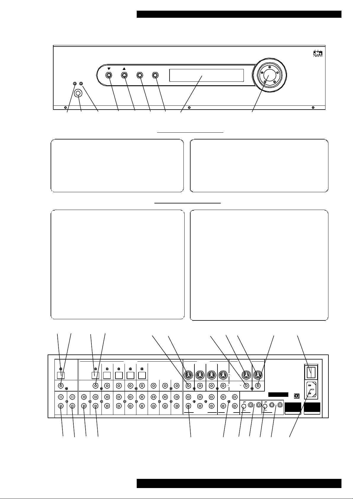
HTP front panel layout
1
1 Standby LED
2 Standby/On switch
3 On LED
4 Source select down
5 Source select up
HTP back panel layout
10 Optical digital output
11 Co-axial digital output
12 5 optical inputs
13 8 co-axial digital inputs
14 4 composite video inputs
15 4 S video inputs
16 Composite video output without OSD
17 S video output without OSD
18 S video output with OSD
19 Composite video output with OSD
20 Main on/off switch
6 Music mode
7 Exit setup without saving
8 Display window and IR receiver
9 Volume and control knob
21 Tape output 1
22 Tape output 2
23 Tape input
24 8 analogue audio inputs
25 6 line level audio outputs
26 Future update option
27 Trigger1 voltage select switch
28 Trigger 1 output jacks
29 Trigger2 voltage select switch
30 Trigger 2 output jacks
31 IEC mains inlet
10 11 12 13 14 15 16 17 18 19 20
OUT 1
AUDIO INPUTS
OPTICAL
OPTICAL
DIGITAL
DIGITAL
INPUTS
OUTPUT
COAXIAL
COAXIAL
DIGITAL
DIGITAL
OUTPUT
INPUTS
TAPE
OUT 2
TAPE
IN
321
TAPE
MUSICAL FIDELITY
HTP HOME THEATRE
PROCESSOR
MANUFACTURED IN ENGLAND
BY MUSICAL FIDELITY
87654 OPTIONSAUDIO OUTPUTS
VIDEO INPUTS
21 3 4
R RS
SLSL
C
'S' VIDEO
COMPOSITE
WR RB
VIDEO OUTPUTS
WITHOUT OSD
LBAH
12v
THIS PRODUCT COMPLIES WITH DHHS RULES 21 CFR
CHAPTER 1, SUBCHAPTER J, PART 1040 AT DATE OF
MANUFACTURE.
WITH OSD
THIS PRODUCT COMPLIES WITH PART 15 OF THE FCC
RULES. OPERATION IS SUBJECT TO TWO CONDITIONS:
1 THIS DEVICE MAY NOT CAUSE HARMFUL
HARMFUL INTERFERENCE, AND
2 THIS DEVICE MUST EXCEPT ANY INTERFERENCE
RECIEVED INCLUDING INTERFERENCE THAT MAY
CAUSE UNDESIRED OPERATION.
CAUTION
MOUNT UNIT ON SOLID SURFACE. DO NOT REMOVE
SCREWS OR COVERS UNDER ANY CIRCUMSTANCES. NO
USER SERVICEABLE COMPONENTS INSIDE.
REFER SERVICING TO QUALIFIED ENGINEER. SEE OWNERS
MANUAL FOR FURTHER INFORMATION.
B
POWER CONSUMPTION 40W
5v
0
AA
12v
TRIGGERS 2TRIGGERS 1
B
5v
0
21 22 23 24 25 26 27 28 29 30 31
issue 2/11.07.2000
HTP Home Theatre Processor Instructions for Use. Page 6
of 28
MUSICAL FIDELITY
HTP
1 2
STANDBY
3
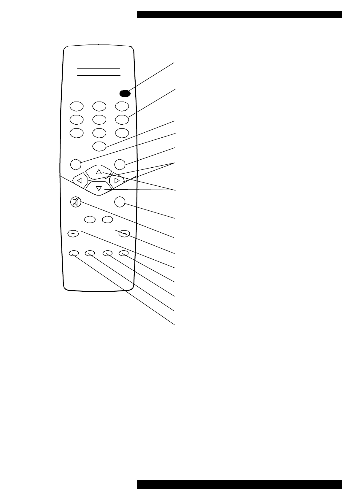
REMOTE CONTROL
STANDBY used to switch the unit from standby to on and
from on back into standby.
DIRECT ACCESS INPUT BUTTONS Use buttons 1 to 8
and Tape to directly select the required input.
7 8
M
+
SUB
WOOFER
STATUS DISPLAY
MM
TRIM
CONTROL
+
SURROUND
LATE
NIGHT
654
TA
OK
X
TAPE
MONITOR
Used to scroll the different available music modes.
Used to enter and leave the set-up menu.
Use whilst navigating the set-up menus.
During normal operation the left and right arrows are used to
increase or decrease the input channel number selected.
In set up mode, they are used when navigating the menus
During normal operation the up and down arrows are used to
increase or decrease the volume.
In set up mode they are used, when navigating the menus
Use to exit setup at any time WITHOUT saving any
changes you have made.
Use to mute and un-mute the audio outputs of the HTP
Use to temporarily trim the level of the surround speakers.
Use to temporarily trim the level of the subwoofer.
Use to select and de-select tape input for tape monitoring.
Use to activate Late Night function.
Use to dim the display or return to normal brightness.
Use to display (only when OSD is active) status of the
incoming audio and video signals.
REMOTE CONTROL
The following should be noted when operating the HTP using the remote control. The Infra Red receiver is
located behind the window for the display on the front panel. It is important to ensure that when operating the
remote control, the line-of-sight from the remote to the infra red receiver is not obstructed.
- Point the remote control (transmitter) towards the front panel display window on the HTP.
- Visual contact must exist between the transmitter and receiver.
- If the range of the remote control decreases dramatically, replace the
batteries with new ones. (dispose of old batteries as per the manufacturers instructions)
- For your convenience MENU, OK, MUTE, EXIT and the cursor keys are all back lit. If any one of these
buttons are pressed, all of these buttons will light up.
issue 2/11.07.2000
HTP Home Theatre Processor Instructions for Use. Page 7

of 28
AUDIO CONNECTIONS
ANALOGUE INPUTS 1…8
Connect the L and R audio output cables of any analogue devices to these sockets. Always connect these inputs,
even when you are going to listen only via digital inputs (such sources as DVD or CD players). This ensures that
there is always a signal at the tape record outputs.
The signal coming from any selected ANALOGUE audio input is fed through an A/D converter that turns the ana logue signal into digital form (A/D = Analogue to Digital). The signal is now ready for Dolby Pro Logic decoding
or post-processing with Music Modes. Then the signal is fed to D/A converter and to 5.1 Channel outputs
TAPE INPUT/OUTPUT
These inputs are suitable for all types of tape recorders, including three-head types, which allow you to monitor the
signal from the tape at the same time it is being recorded. Connect a set of interconnects from the TAPE REC output sockets of the preamp to the LINE IN or RECORD IN sockets of your tape recorder. Connect a second set of
cables from the TAPE PLAY input sockets to the LINE OUT or PLAY OUT sockets of your tape recorder.
Using the TAPE loop you can monitor the level and quality of the recording, at the same time as the recording
takes place. You can also use it for connecting external devices (such as an equaliser) to the signal path. Note: If
you use an equaliser you must bypass it when listening to a Dolby surround source being decoded by Dolby
ProLogic.
Any ANALOGUE stereo source you have selected on the HTP will be automatically fed to the TAPE REC output
sockets for recording. You cannot make a recording from a source that is connected to the digital inputs.
RECORD OUTPUTS 1…2
The REC outputs carry the signal from the currently selected ANALOGUE stereo source device (except the source
connected to the TAPE PLAY input). You can connect these outputs to the inputs of any recording device. The
signal can also be used in a multi-room set-up to feed power amplifiers in other rooms.
5.1 CHANNEL OUTPUTS (LEFT FRONT, RIGHT FRONT, LEFT SURROUND, RIGHT SURROUND CENTRE AND SUBWOOFER)
Connect these outputs to the line inputs of your power amplifiers. The SUB output is normally fed to the low-level
Line Input of an active subwoofer. Alternatively it may feed a separate power amplifier and a passive subwoofer.
The option outputs are reserved for future surround formats.
COAXIAL DIGITAL AUDIO INPUTS 1…8
Connect the coaxial digital output cables from your source devices to these inputs.
OPTICAL DIGITAL AUDIO INPUTS 1...5
Connect the optical digital output cables from your source devices to these inputs.
PLEASENOTE. It is possible to connect both optical and coaxial digital cables to inputs 1 through to 5. This is
not reccomended but if you choose to connect both cables, the HTP will use the optical source.
OPTICAL DIGITAL OUTPUT
Connect the optical input of your digital recorder to the DIGITAL output. The selected digital source is fed to this
output in digital format.
COAXIAL DIGITAL OUTPUT
Connect the coaxial input of your digital recorder to the DIGITAL output. The selected digital source is fed to this
output in digital format.
issue 2/11.07.2000
HTP Home Theatre Processor Instructions for Use. Page 8

of 28
VIDEO CONNECTIONS
COMPOSITE VIDEO INPUTS 1…4
Connect the composite video output cables coming from your video sources to these inputs.
The composite video signal is selected from the input signals, and then fed to the composite video outputs.
Note: Take care to use the same number input for both the video and audio connections from the source device.
i.e. DVD player:- video to video input 1 and the digital audio of the same DVD player to either the optical or
coaxial digital input 1
COMPOSITE VIDEO OUTPUTS
There are two composite video outputs. Both will display the selected source on the display device i.e. TV or
projector. Only one will have the On Screen Display information.
Connect either Composite Video output to your display device .
On Screen Display information, is only output to the COMPOSITE VIDEO OUTPUT WITH OSD.
S-VIDEO INPUTS 1…4
Connect the S-Video output cables from your video sources to these inputs.
Note: Take care to use the same number input for both the video and audio connections from the source device.
S-Video signals are of higher quality than Composite Video signals. If you have a source device with S-Video
outputs, we recommend you to use them together with the S-Video inputs on your display device. S-Video inputs
are automatically down-mixed, to feed the Composite Video outputs for displays that are without S-Video inputs.
S-VIDEO OUTPUT
There are two S-Video outputs. Both will display the selected source on the display device. Only one will have
the On Screen Display information.
Connect either S-Video output to your display device.
On Screen Display information is only output to S- VIDEO OUTPUT WITH OSD.
PLEASE NOTE:-
Do not connect a composite video signal input to the HTP (i.e. from a DVD player) and then connect the output of
the HTP to the display device using S-Video.
issue 2/11.07.2000
HTP Home Theatre Processor Instructions for Use. Page 9
 Loading...