

Musical Fidelity E-20 Owners manual

E20 REMOTE CONTROL STEREO
PREAMPLIFIER
INSTRUCTIONS FOR USE
Thank you for purchasing the Musical Fidelity
Elektra E20 Preamplifier . Used properly and carefully, it should give you many years of outstanding
musical reproduction.
The E20 is the result of many years painstaking
research and development. The E20 is designed for
ultra-high definition performance and is equipped
with full remote control facilities.
Aesthetically, the E20 is a perfect match for the
Elektra E30 power amplifier, E50 tuner and the E60
CD player. Together, they form one of the finest hi fi
systems that you can own today.
Dust regularly with a soft duster or soft brush but
do not use cleaning or polishing agents - they may harm
the surface finish.
If you have any questions about anything in your
audio system, please consult your dealer who is there
to help and advise you.
Instructions For Use. Page 1E20

PLEASE READ
IMPORTANT!
This unit is supplied in the UK with a mains lead fitted with a moulded 13 amp
plug. If, for any reason, you need to cut off this plug, please observe the following
safety precautions. Please dispose of the cut-off plug safely. It must not be plugged
into a mains power supply.
The wires in the mains lead supplied with this appliance are coloured in ac-
cordance with the following code:
Green and yellow..............Earth
Blue...............................Neutral
Brown................................Live
WARNING - This appliance must be earthed
As the colours of the wires of the mains lead of this appliance may not correspond with the coloured markings identifying the terminals in your plug, proceed as
follows:
•The wire which is coloured green-and-yellow must be connected to the terminal in the plug which is marked with the letter E or coloured green or green-andyellow, or by the earth symbol .
•The wire which is coloured brown must be connected to the terminal which is
marked with the letter L or coloured red.
•The wire which is coloured blue must be connected to the terminal which is
marked with the letter N or coloured black.
•If connecting to a BS1363 plug, a 10 amp fuse must be used.
WARNING - Radio Frequency Interference (RFI)
This hi-fi product has been tested to ensure that its operation will not be adversely affected by normal background levels of RFI. It is possible that if this product is subjected to abnormally high levels of RFI the unit may be susceptible and not
perform as expected. In the unlikely event of this happening on a regular basis,
please contact Musical Fidelity's service department.
The unit has also been tested to ensure that it does not radiate excessive levels
of RFI that could affect other pieces of electronic or electrical equipment.
The electronics in modern hi-fi equipment is complex and hence may be damaged by lightning. It is possible that during electrical storms the operation of some
equipment may be adversely affected. For complete protection of your hi-fi system
during such storms, mains plugs should be removed from sockets and aerial leads
disconnected.
Always ensure that when disconnecting and reconnecting your hi-fi equipment
the mains supply is switched off.
Instructions For Use. Page 2E20
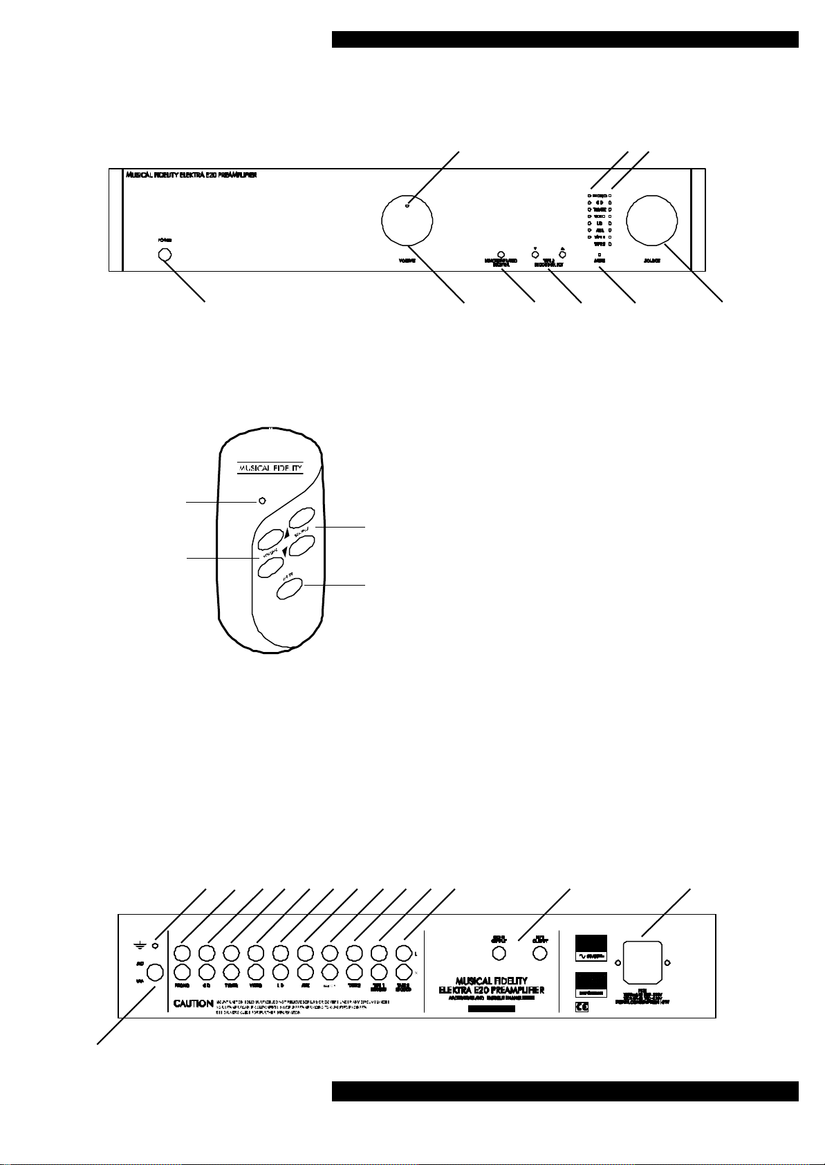
1 2 3 4 5 6
A
B
REMOTE CONTROL
A Remote operation LED
B Volume Up/Down buttons
C Source selector buttons
D Mute Button
CONNECTIONS AND FACILITIES
7 8 9
FRONT PANEL
1 Power on/off switch
2 Volume control knob
3 Remote receiver lens
4 Tape 2 record selectors
5 Mute indicator
6 Source selector knob
7 LED, indicates volume setting
C
D
8 Output to Tape 2 indicators
9 Source (listen) indicators
BACK PANEL
10 Phono/Chassis Earth
11 Phono cartridge type button
12 Phono input
13 CD input
14 Tuner input
15 Video input
16 Laser Disc input
17 Auxiliary input
18 Tape 1 input
19 Tape 2 input
20 Tape 1 record output
21 Tape 2 record output
22 Preamp outputs
23 IEC mains inlet/ fuseholder
11
10 12 13 14 15 16 17 18 19 20 21 22 23
Instructions For Use. Page 3E20
 Loading...