

Page 1
769-08353 / 00 08/12
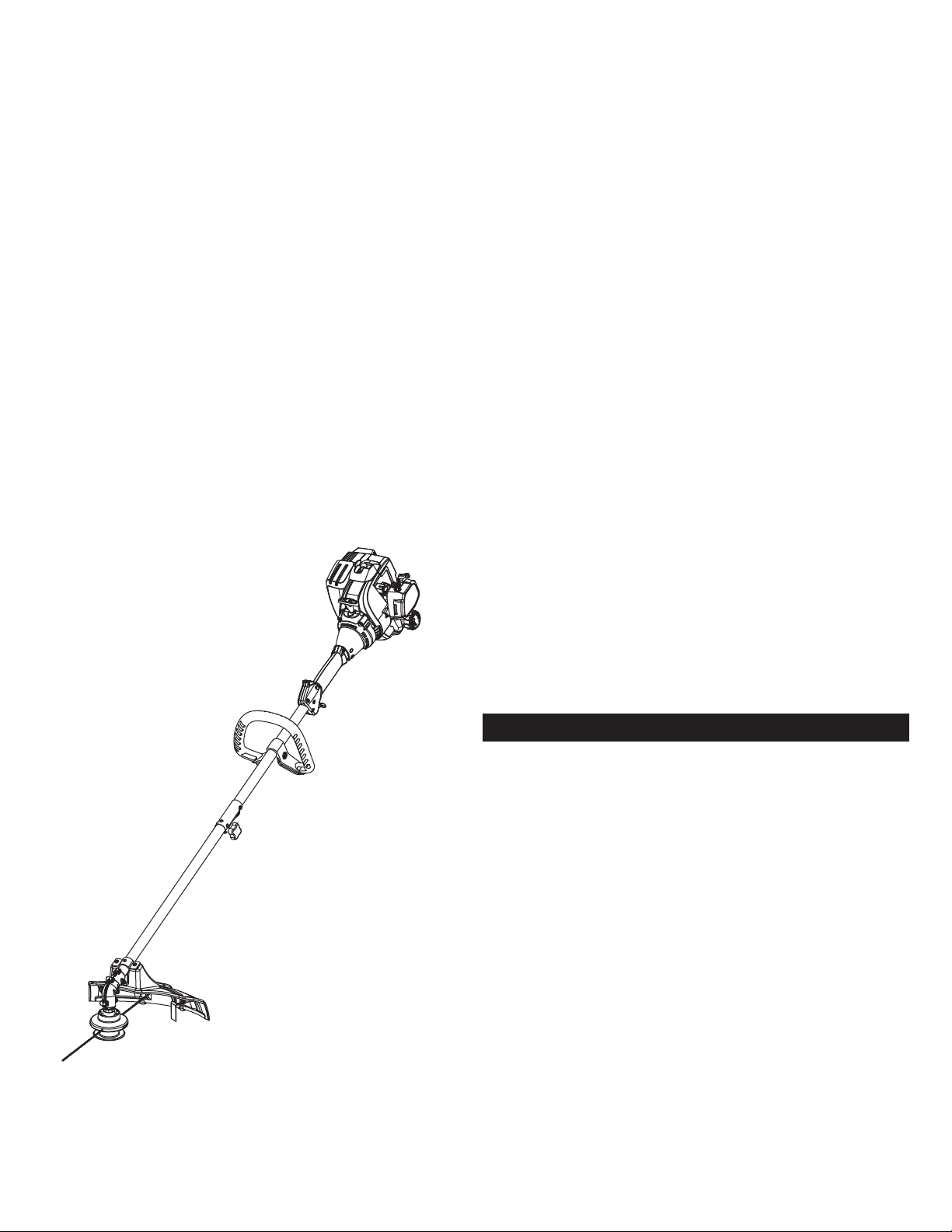
Operator’s Manual
2-Cycle Trimmer
TABLE OF CONTENTS
Service . . . . . . . . . . . . . . . . . . . . . . . . . . . . . . . . . . . . . . . . . . . . . . .1
Safety . . . . . . . . . . . . . . . . . . . . . . . . . . . . . . . . . . . . . . . . . . . . . . .2
Know Your Unit . . . . . . . . . . . . . . . . . . . . . . . . . . . . . . . . . . . . . . . .5
Specifications . . . . . . . . . . . . . . . . . . . . . . . . . . . . . . . . . . . . . . . . .5
Assembly . . . . . . . . . . . . . . . . . . . . . . . . . . . . . . . . . . . . . . . . . . . . .6
Oil and Fuel . . . . . . . . . . . . . . . . . . . . . . . . . . . . . . . . . . . . . . . . . . .8
Starting and Stopping . . . . . . . . . . . . . . . . . . . . . . . . . . . . . . . . . . .9
Operation . . . . . . . . . . . . . . . . . . . . . . . . . . . . . . . . . . . . . . . . . . . .10
Maintenance . . . . . . . . . . . . . . . . . . . . . . . . . . . . . . . . . . . . . . . . .11
Cleaning and Storage . . . . . . . . . . . . . . . . . . . . . . . . . . . . . . . . . .14
Troubleshooting . . . . . . . . . . . . . . . . . . . . . . . . . . . . . . . . . . . . . . .15
Warranty . . . . . . . . . . . . . . . . . . . . . . . . . . . . . . . . . . . . . . . . . . . .16
All information, illustrations, and specifications in this manual are based
on the latest product information available at the time of printing. We
reserve the right to make changes at any time without notice.
Copyright© 2012 MTD SOUTHWEST INC, All Rights Reserved.
DO NOT RETURN THIS UNIT TO THE RETAILER. PROOF OF
PURCHASE WILL BE REQUIRED FOR WARRANTY SERVICE.
For assistance regarding the assembly, controls, operation or
maintenance of the unit, please call the Customer Support Department
at 1-800-800-7310 in the United States or 1-800-668-1238 in Canada.
Additional information about the unit can be found on our website:
www.mtdproducts.com (U.S.) or www.mtdproducts.ca (Canada).
For service, please call the Customer Support Department to obtain
a list of authorized service dealers near you. Service on this unit,
both within and after the warranty period, should only be performed
by an authorized and approved service dealer. When servicing, use
only identical replacement parts.
SAVE THESE INSTRUCTIONS
SERVICE
Page 2
SAFETY
SPARK ARRESTOR NOTE
NOTE: For users on U.S. Forest Land and in the states of
California, Maine, Oregon and Washington. All U.S. Forest Land
and the state of California (Public Resources Codes 4442 and
4443), Oregon and Washington require, by law that certain internal
combustion engines operated on forest brush and/or grass-covered
areas be equipped with a spark arrestor, maintained in effective
working order, or the engine be constructed, equipped and
maintained for the prevention of fire. Check with your state or local
authorities for regulations pertaining to these requirements. Failure
to follow these requirements could subject you to liability or a fine.
This unit is factory equipped with a spark arrestor. If it requires
replacement, ask your LOCAL SERVICE DEALER to install the
Accessory Part #753-06418 Muffler Assembly.
Read the operator’s manual and follow all warnings and safety
instructions. Failure to do so can result in serious injury to the
operator and/or bystanders.
SYMBOL MEANING
WARNING:
Signals a SERIOUS hazard.
Failure to obey a safety WARNING signal CAN result in
serious injury to yourself or to others.
CAUTION:
Signals a MODERATE hazard.
Failure to obey a safety CAUTION signal MAY result in
property damage or injury to yourself or to others.
The purpose of safety symbols is to attract your attention to
possible dangers. The safety symbols, and their explanations,
deserve your careful attention and understanding. The safety
warnings do not by themselves eliminate any danger. The
instructions or warnings they give are not substitutes for proper
accident prevention measures.
NOTE: Advises you of information or instructions vital to the
operation or maintenance of the equipment.
DANGER:
Signals an EXTREME hazard.
Failure to obey a safety DANGER signal WILL result in
serious injury or death to yourself or to others.
CALIFORNIA PROPOSITION 65
WARNING:
Engine exhaust, some of its constituents and
certain finished components contain or emit chemicals known
to the State of California to cause cancer and birth defects or
other reproductive harm. Wash hands after handling.
2
Page 3

READ ALL INSTRUCTIONS BEFORE OPERATING
• Read the instructions carefully. Be familiar with the controls and
proper use of the unit.
• Do not operate this unit when tired, ill or under the influence of
alcohol, drugs or medication.
• Children must not operate the unit. Teens must be accompanied
and guided by an adult.
• All guards and safety attachments must be installed properly
before operating the unit.
• Inspect the unit before use. Replace damaged parts. Check for
fuel leaks. Make sure all fasteners are in place and secure.
Replace parts that are cracked, chipped, or damaged in any
way. Do not operate the unit with loose or damaged parts.
• Only use the trimming line described in the Specifications section
of this manual. Never use metal-reinforced line, wire, chain or
rope. These can break off and become dangerous projectiles.
• Be aware of risk of injury to the head, hands and feet.
• Carefully inspect the area before starting the unit. Remove
rocks, broken glass, nails, wire, string and other objects that
may be thrown or become entangled with the unit.
• Clear the area of children, bystanders and pets; keep them
outside a 50-foot (15 m) radius, at a minimum. Even then, they are
still at risk from thrown objects. Encourage bystanders to wear
eye protection. If you are approached, stop the unit immediately.
• Squeeze the throttle control and check that it returns
automatically to the idle position. Make all adjustments or
repairs before using the unit.
WHILE OPERATING
• Wear safety glasses or goggles that meet current ANSI Z87.1
standards and are marked as such. Wear ear/hearing protection
when operating this unit. Wear a face mask or dust mask if the
operation is dusty.
• Wear heavy long pants, boots, gloves and a long sleeve shirt. Do
not wear loose clothing, jewelry, short pants, sandals or go
barefoot. Secure hair above shoulder level.
• The cutting head shield must always be in place while operating
the unit. Do not operate the unit without both trimming lines
extended and the proper line installed. Do not extend the
trimming line beyond the length of the shield.
• This unit has a clutch. The cutting head remains stationary when
the engine is idling. If it does not, take the unit to an authorized
service dealer for an adjustment.
• Adjust the handle to provide the best grip.
• Make sure the cutting head is not in contact with anything
before starting the unit.
• Use the unit only in daylight or good artificial light.
• Avoid accidental starting. Be in the starting position whenever
pulling the starter rope. The operator and unit must be in a stable
position while starting. Refer to Starting and Stopping.
• Use the right tool. Only use this tool for its intended purpose.
• Always hold the unit with both hands when operating. Keep a
firm grip on both handles or grips.
• Do not overreach. Always keep proper footing and balance. Take
extra care when working on steep slopes or inclines.
• Keep hands, face, and feet away from all moving parts. Do not
touch or try to stop moving parts.
• Do not touch the engine, gear housing or muffler. These parts get
extremely hot from operation, even after the unit is turned off.
• Do not operate the unit faster than the speed needed to do the job.
Do not run the unit at high speed when not in use.
• Do not force the unit. It will do a better, safer job when used at
the intended rate.
• Always stop the unit when operation is delayed or when walking
from one location to another.
• If you strike or become entangled with a foreign object, stop the
unit immediately and check for damage. Do not operate the unit
before repairing damage. Do not operate the unit with loose or
damaged parts.
• Turn the engine to off and disconnect the spark plug for
maintenance or repair.
• Use only original equipment manufacturer (OEM) replacement
parts and accessories for this unit. These are available from your
authorized service dealer. Use of any other parts or accessories
could lead to serious injury to the user, or damage to the unit,
and void the warranty.
• Keep the unit clean. Carefully remove vegetation and other
debris that could block moving parts.
• To reduce fire hazard, replace a faulty muffler and spark arrestor.
Keep the engine and muffler free from grass, leaves, excessive
grease or carbon build up.
• If the unit starts to vibrate abnormally, stop the unit immediately.
Inspect the unit for the cause of the vibration. Vibration is
generally an indicator of trouble.
SAFETY WARNINGS FOR GAS UNITS
• Store fuel only in containers specifically designed and approved
for the storage of such materials.
• Always stop the engine and allow it to cool before filling the
tank. Never remove the fuel tank cap or add fuel when the
engine is hot. Always loosen the fuel tank cap slowly to relieve
any pressure in the tank before fueling.
• Always mix and add fuel in a clean, well-ventilated outdoor area
where there are no sparks or flames. DO NOT smoke.
• Never operate the unit without the fuel cap securely in place.
• Avoid creating a source of ignition for spilled fuel. Wipe up any
spilled fuel from the unit immediately, before starting the unit.
Move the unit at least 30 ft. (9.1 m) from the fueling source and
site before starting the engine. DO NOT smoke.
• Never start or run the unit inside a closed room or building.
Breathing exhaust fumes can kill. Operate this unit only in a well
ventilated outdoor area.
• IMPORTANT SAFETY INSTRUCTIONS •
WARNING:
When using the unit, all safety rules must be
followed. Please read these instructions before operating
the unit in order to ensure the safety of the operator and any
bystanders. Please keep these instructions for later use.
WARNING:
Gasoline is highly flammable and its vapors
can explode if ignited. Take the following precautions:
3
Page 4
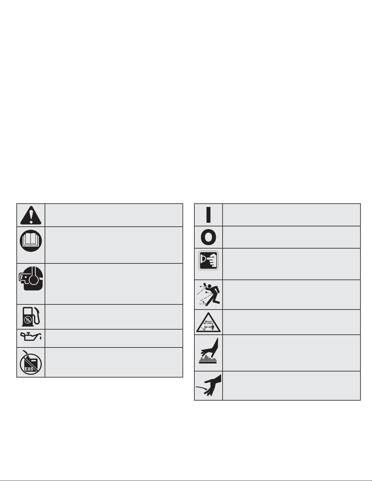
• SAFETY & INTERNATIONAL SYMBOLS •
This operator's manual describes safety and international symbols and pictographs that may appear on this product. Read the operator's
manual for complete safety, assembly, operating and maintenance and repair information.
SYMBOL MEANING SYMBOL MEANING
• SAFETY ALERT SYMBOL
Indicates danger, warning or caution. May be used in
conjunction with other symbols or pictographs.
• READ OPERATOR'S MANUAL
WARNING: Read the operator’s manual(s) and
follow all warnings and safety instructions. Failure to
do so can result in serious injury to the operator
and/or bystanders.
• WEAR EYE AND HEARING PROTECTION
WARNING: Thrown objects and loud noise can
cause severe eye injury and hearing loss. Wear eye
protection meeting current ANSI Z87.1 standards and
ear protection when operating this unit. Use a full face
shield when needed.
• UNLEADED FUEL
Always use clean, fresh unleaded fuel.
• OIL
Refer to operator’s manual for the proper type of oil.
• DO NOT USE E85 FUEL IN THIS UNIT
WARNING: It has been proven that fuel containing
greater than 10% ethanol will likely damage this
engine and void the warranty.
• ON/OFF STOP CONTROL
ON / START / RUN
• ON/OFF STOP CONTROL
OFF or STOP
• PRIMER BULB
Push primer bulb, fully and slowly, 10 times.
• THROWN OBJECTS AND ROTATING CUTTER CAN
CAUSE SEVERE INJURY
WARNING: Small objects can be propelled at high
speed, causing injury. Keep away from the rotating rotor.
• KEEP BYSTANDERS AWAY
WARNING: Keep all bystanders, especially children
and pets, at least 50 feet (15 m) from the operating area.
• HOT SURFACE
WARNING: Do not touch a hot muffler or cylinder.
You may get burned. These parts get extremely hot
from operation. When turned off they remain hot for a
short time.
• SHARP BLADE
WARNING: Sharp blade on trimmer attachment
shield. To prevent serious injury, do not touch the line
cutting blade.
4
OTHER SAFETY WARNINGS
• All service, other than the maintenance procedures described in
this manual, should be performed by a qualified service dealer.
• Before inspecting, servicing, cleaning, storing, transporting or
replacing any parts on the unit:
1. Stop the unit.
2. Make sure all moving parts have stopped.
3. Allow the unit to cool.
4. Disconnect the spark plug wire.
• Secure the unit while transporting.
• Never store the unit with fuel in the tank, inside a building where
fumes may reach an open flame (pilot lights, etc.) or sparks
(switches, electrical motors, etc.).
• Store the unit in a dry place, secured or at a height to prevent
unauthorized use or damage. Keep the unit out of the reach of
children.
• Never douse or squirt the unit with water or any other liquid.
Keep handles dry, clean and free from debris. Clean the unit
after each use. Refer to Cleaning and Storage.
• Keep these instructions. Refer to them often and use them to
instruct other users. If you loan this unit to others, also loan
them these instructions.
SAVE THESE INSTRUCTIONS
Page 5
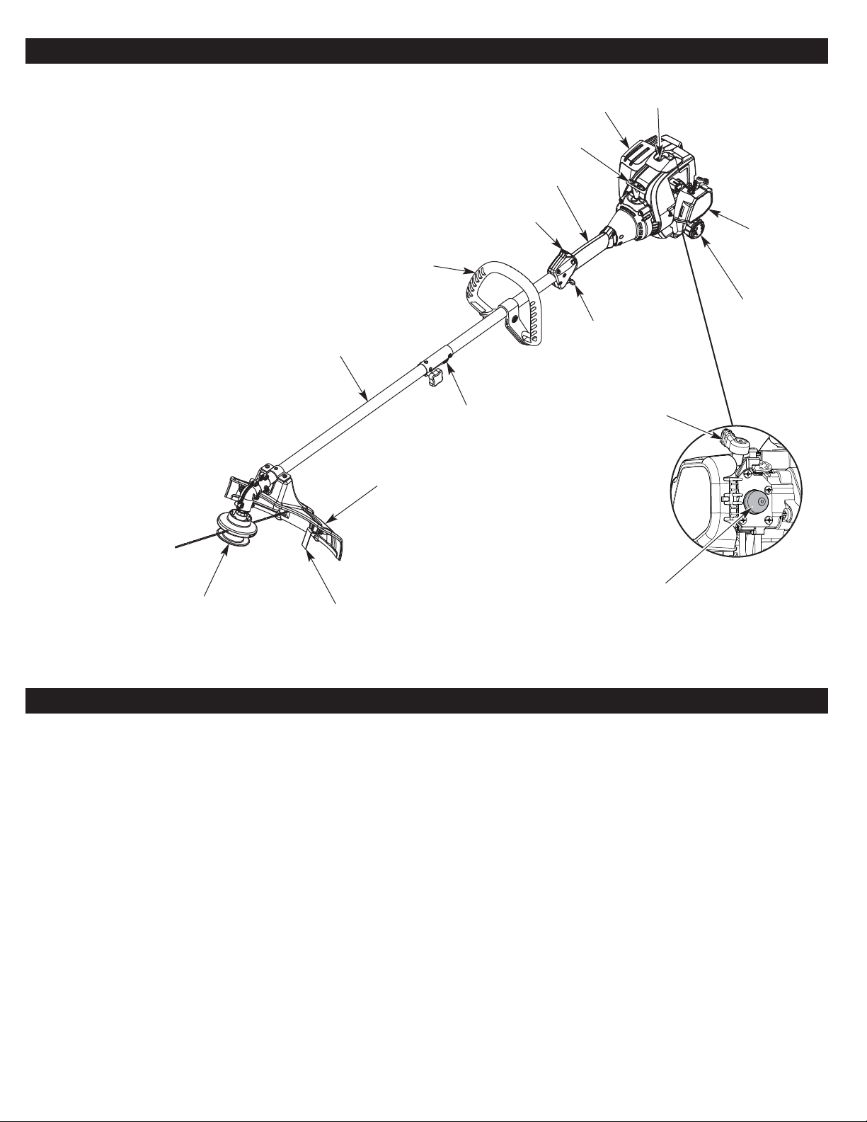
Cutting Head
Shield
Fuel Cap
Handle
Cutting Head
Shaft Grip
Shaft Housing
Starter
Rope Grip
Throttle
Control
Spark Plug
Muffler
On/Off Switch
Line Cutting Blade
Air Filter
Cover
Coupler
Primer Bulb
Choke Lever
5
KNOW YOUR UNIT
APPLICATIONS
As a trimmer:
• Cutting grass and light weeds.
• Edging
• Decorative trimming around trees, fences, etc.
Other optional accessories may be used with this unit.
SPECIFICATIONS*
* All specifications are based on the latest product information available at the time of printing. We reserve the right to make changes at any
time without notice.
Engine Type. . . . . . . . . . . . . . . . . . . . . . . . . . . . . . . . . . . . . . . . . . . . . . . . . . . . . . . . . . . . . . . . . . . . . . . . . . . . . . . . . . . . . . . . Air-Cooled, 2-Cycle
Displacement . . . . . . . . . . . . . . . . . . . . . . . . . . . . . . . . . . . . . . . . . . . . . . . . . . . . . . . . . . . . . . . . . . . . . . . . . . . . . . . . . . . . . . . 25 cc (1.52 cu. in.)
Spark Plug Gap . . . . . . . . . . . . . . . . . . . . . . . . . . . . . . . . . . . . . . . . . . . . . . . . . . . . . . . . . . . . . . . . . . . . . . . . . . . . . . . . . . . . 0.025 in. (0.635 mm)
Spark Plug . . . . . . . . . . . . . . . . . . . . . . . . . . . . . . . . . . . . . . . . . . . . . . . . . . . . . . . . . . . . . . . . . . . . . . . . . . Champion® RDJ7J or equivalent plug
Lubrication. . . . . . . . . . . . . . . . . . . . . . . . . . . . . . . . . . . . . . . . . . . . . . . . . . . . . . . . . . . . . . . . . . . . . . . . . . . . . . . . . . . . . . . . . . . . Fuel/Oil Mixture
Fuel/Oil Ratio . . . . . . . . . . . . . . . . . . . . . . . . . . . . . . . . . . . . . . . . . . . . . . . . . . . . . . . . . . . . . . . . . . . . . . . . . . . . . . . . . . . . . . . . . . . . . . . . . . 40:1
Fuel Tank Capacity . . . . . . . . . . . . . . . . . . . . . . . . . . . . . . . . . . . . . . . . . . . . . . . . . . . . . . . . . . . . . . . . . . . . . . . . . . . . . . . . . . . . . . 10 oz. (296 ml)
Approximate Unit Weight (No fuel, with cutting head, cutting head shield and handle) . . . . . . . . . . . . . . . . . . . . . . . . . . . 10 - 11 lbs. (4.5 - 5 kg)
Trimmer Mechanism . . . . . . . . . . . . . . . . . . . . . . . . . . . . . . . . . . . . . . . . . . . . . . . . . . . . . . . . . . . . . . . . . . . . . . . . . . . . . . Fixed-line cutting head
Trimming Line. . . . . . . . . . . . . . . . . . . . . . . . . . . . . . . . . . . . . . . . . . . . . . . . . . . . . . . . . . . . . . . . . . . . . . . . . . 0.095 inches (2.41 mm) pre-cut line
Cutting Path Diameter . . . . . . . . . . . . . . . . . . . . . . . . . . . . . . . . . . . . . . . . . . . . . . . . . . . . . . . . . . . . . . . . . . . . . . . . . . . . . . . . . . 14 in. (35.56 cm)
ASSEMBLY TOOLS REQUIRED:
• #2 Phillips screwdriver
• 3/8” Socket
Page 6
ASSEMBLY
6
INSTALLING AND ADJUSTING THE HANDLE
Installing the Handle
1. Push the handle down onto the shaft housing (Fig. 2). The bolt
hole in the handle should be to the right.
2. Insert the bolt into the bolt hole and push it through (Fig. 2).
Tighten the bolt with a 3/ 8” socket, but do not tighten the bolt
completely .
3. While holding the unit in the operating position (Fig. 10), move
the handle to the location that provides the best grip. Place it a
minimum of 6 inches (15.24 cm) from the end of the shaft grip
(Fig. 2).
4. Tighten the bolt with a 3/ 8” socket until the handle is secure.
Adjusting the Handle
If the handle requires adjustment:
1. Loosen the bolt with a 3/ 8” socket (Fig. 2).
2. While holding the unit in the operating position (Fig. 10), move
the handle to the location that provides the best grip. Place it a
minimum of 6 inches (15.24 cm) from the end of the shaft grip
(Fig. 2).
3. Tighten the bolt with a 3/ 8” socket until the handle is secure.
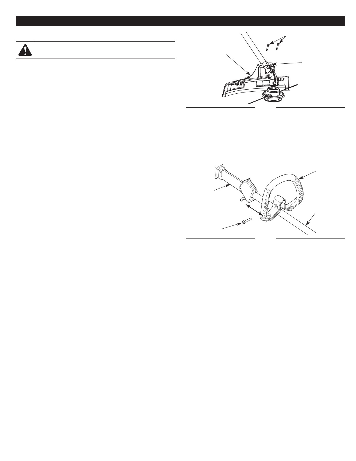
INSTALLING THE CUTTING HEAD SHIELD
Use the following instructions if the cutting head shield is not
installed. Use only the instructions that apply to the type of shaft
and shield equipped with this unit.
1. Place the cutting head shield onto the mount bracket. Align the
holes in the cutting head shield with the holes in the mount
bracket. (Fig. 1)
2. Screw the 2 screws through the mount bracket and into the
cutting head shield until finger tight.
3. Using a #2 Phillips screwdriver, tighten the screws until the
cutting head shield is firmly in place. Tighten the screws equally.
The gap between the mount bracket and the cutting head shield
should be the same on each side.
Fig. 1
Mount Bracket
Cutting Head
Shield
Screws (2)
WARNING:
To prevent serious personal injury, never
operate the unit without the cutting head shield in place.
Fig. 2
Bolt
Shaft Grip
Minimum 6 in.
(15.24 cm)
Handle
Shaft
Housing
Page 7
7
Fig. 4
Fig. 5
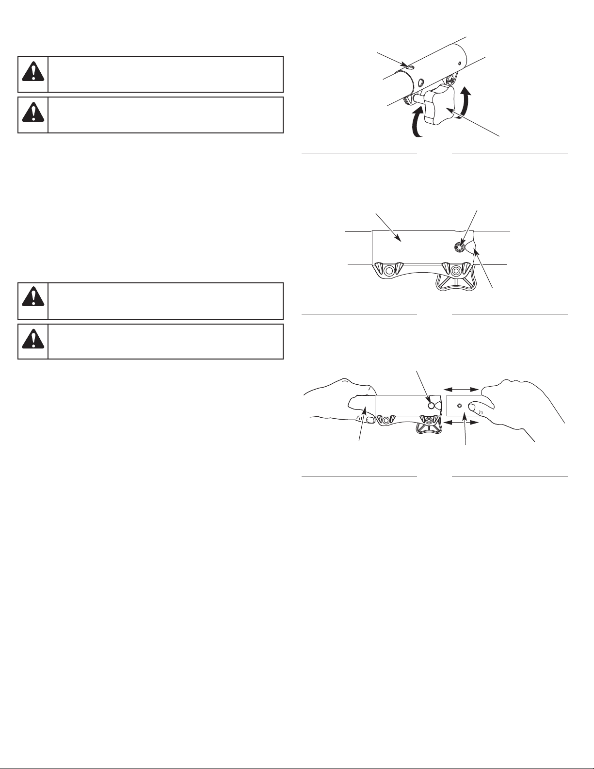
Fig. 3
Release Button
Guide Recess
90˚ Edging Hole
(Trimmer Only)
Knob
Primary Hole
Lower Shaft
Housing
Upper Shaft
Housing
OPERATING THE COUPLER
The coupler enables the use of various optional attachments.
NOTE: To make installing or removing the attachment easier, place
the unit on the ground or on a work bench.
Installing the Attachment
NOTE: Remove the protective cap and gray spacer from the upper
and lower shafts prior to assembling the attachment.
1. Turn the knob counterclockwise to loosen (Fig. 3).
2. While firmly holding the attachment, push it straight into the
coupler until the release button snaps firmly into the primary
hole (Fig. 5).
NOTE: Aligning the release button with the guide recess will help
installation (Fig. 4).
3. Turn the knob clockwise to tighten (Fig. 3).
For decorative edging with a string trimmer attachment, lock the
release button into the 90° edging hole (Fig. 3).
Removing the Attachment
1. Turn the knob counterclockwise to loosen (Fig. 3).
2. Press and hold the release button (Fig. 4).
3. While firmly holding the upper shaft housing, pull the attachment
straight out of the coupler (Fig. 5).
WARNING:
Before using any attachment, read and
understand the manual that came with the attachment.
Follow all safety information contained within.
CAUTION:
Before operating the unit, make sure the
release button is fully snapped into the primary hole (Fig. 5)
and the knob (Fig. 3) is securely tightened.
WARNING:
To avoid serious personal injury and
damage to the unit, shut the unit off before removing or
installing an attachment.
CAUTION:
The release button should be snapped into
the primary hole only. Using the wrong hole could lead to
personal injury or damage to the unit.
Coupler
Page 8
8
OIL AND FUEL
FUELING THE UNIT
1. Position the unit with the fuel cap facing up.
2. Remove the fuel cap.
3. Place the fuel container spout into the fill hole on the fuel tank
and fill the tank.
NOTE: Do not overfill the tank.
4. Wipe up any fuel that may have spilled.
5. Reinstall the fuel cap.
6. Move the unit at least 30 ft. (9.1 m) from the fuel container and
the fueling site before starting the engine.
OIL AND FUEL MIXING INSTRUCTIONS
The use of old and/or improperly mixed fuel is the most common cause
of performance problems. Use only fresh, clean unleaded gasoline.
Follow the instructions carefully for the proper gasoline/oil mixture.
Definition of Blended Fuels
Today's fuels are often a blend of gasoline and oxygenates such as
ethanol, methanol or MTBE (ether). Alcohol-blended fuel absorbs
water. As little as 1% water in the fuel can make fuel and oil
separate, forming acids when stored. ALWAYS use fresh fuel (less
than 30 days old).
NOTE: Dispose of old fuel according to federal, state and local
regulations.
Using Blended Fuels
If using a blended fuel:
• Always use the fresh fuel mix explained in your operator's manual
• Use the fuel additive STA-BIL® or an equivalent
• Always agitate the fuel mix before fueling the unit
• Drain the tank and run the engine dry before storing the unit
Using Fuel Additives
The bottle of 2-cycle oil provided with this unit contains a fuel
additive to help inhibit corrosion and minimize gum deposits.
Always use the brand of 2-cycle oil that came with this unit. If this is
unavailable, use a 2-cycle oil designed for air-cooled engines and
mix it with a fuel additive, such as STA-BIL Fuel Stabilizer or an
equivalent. Add 0.8 oz. (23 ml) of fuel additive per gallon of fuel,
according to the instructions on the container. NEVER add fuel
additives directly to the unit's fuel tank.
Mixing the Fuel
NOTE: This unit comes with a 3.2 oz. bottle of 2-cycle oil. To obtain
the correct fuel mixture described below, pour the entire bottle
into one gallon of unleaded gasoline.
Thoroughly mix the proper ratio of unleaded gasoline with 2-cycle
engine oil. Do not mix them directly in the unit’s fuel tank. Use a
separate fuel can. Use a 40:1 gasoline/oil ratio. See the table below
for specific gasoline and oil mixing ratios.
Unleaded gasoline 2-cycle oil
1 gallon U.S.
(3.8 liters)
3.2 fl. oz.
(95 ml)
1 liter 25 ml
MIXING RATIO - 40:1
CAUTION:
For proper engine operation and maximum
reliability, pay strict attention to the gasoline and oil mixing
instructions on the 2-cycle oil bottle. Using improperly
mixed fuel can severely damage the engine.
WARNING:
Gasoline is extremely flammable. Ignited
vapors may explode. Always stop the engine and allow it
to cool before filling the fuel tank. Do not smoke while
filling the tank. Keep sparks and open flames at a distance
from the area.
WARNING:
Remove the fuel cap slowly to avoid injury
from fuel spray. Never operate the unit without the fuel cap
securely in place.
WARNING:
Add fuel in a clean, well ventilated outdoor
area. Wipe up any spilled fuel immediately. Avoid creating
a source of ignition for spilled fuel. Do not start the engine
until fuel vapors dissipate.
WARNING:
DO NOT USE E85 FUEL IN THIS UNIT. It
has been proven that fuel containing greater than 10%
ethanol will likely damage this engine and void the warranty.
Page 9
9
STARTING AND STOPPING
WARNING:
Operate this unit only in a well-ventilated
outdoor area. Carbon monoxide exhaust fumes can be
lethal in a confined area.
WARNING:
Avoid accidentally starting the unit. To avoid
serious injury, the operator and the unit must be in a stable
position when pulling the starter rope (Fig. 9).
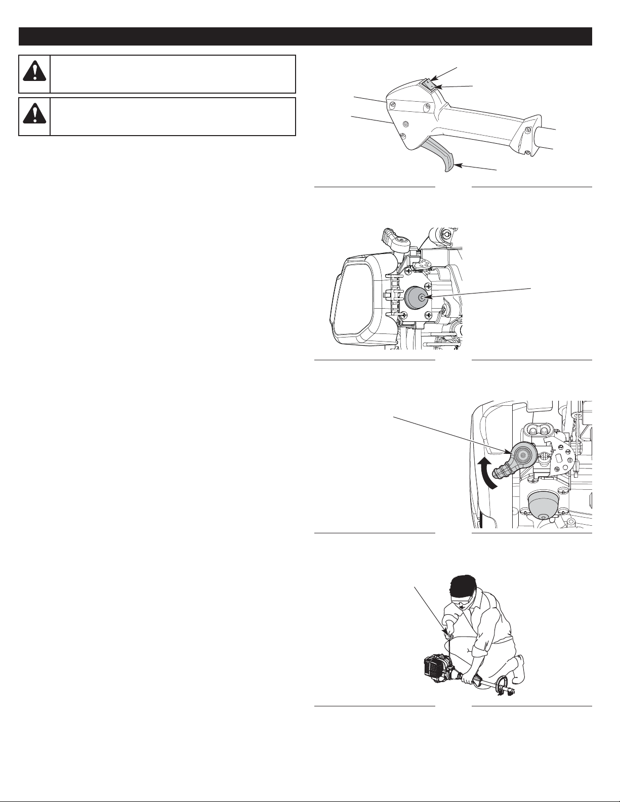
STARTING INSTRUCTIONS
1. Mix gasoline with oil. Refer to Oil and Fuel Mixing Instructions.
2. Fill the fuel tank. Refer to Fueling the Unit.
NOTE: There is no need to turn the unit on. The On/Off switch is in
the ON ( I ) position at all times (Fig. 6).
3. Slowly press and release the primer bulb 10 times (Fig. 7). If fuel
cannot be seen in the primer bulb, press and release the primer
bulb until fuel is visible.
4. Flip the choke lever clockwise until it clicks (Fig. 8).
5. Crouch in the starting position (Fig. 9).
6. DO NOT squeeze the throttle control (Fig. 6). Pull the starter
rope with a controlled and steady motion until the unit starts
(Fig. 9).
7. Idle the engine for 5 to 10 seconds. If the unit stops during this
time, squeeze the throttle control and pull the starter rope in a
controlled and steady motion until the unit starts.
8. Squeeze and hold the throttle control. Allow the engine to warm
up for 30 to 60 seconds.
NOTE: The engine is properly warmed up when it accelerates
without hesitation.
IF... the engine does not start, begin the starting procedure with
step 3.
IF... the unit is hot and fails to start within 3 pulls of the starter rope,
squeeze the throttle control and pull the starter rope with a
controlled and steady motion until the unit starts.
STOPPING INSTRUCTIONS
1. Release the throttle control and allow the engine to idle.
2. Press and hold the On/Off switch in the OFF (O) position until
the engine comes to a complete stop (Fig. 6).
Fig. 6
On ( I ) / Start
Off (O) / Stop
Throttle Control
Fig. 9
Starting
Position
Starter Rope Grip
Fig. 7
Primer Bulb
Fig. 8
Choke Lever
Page 10
10
OPERATION
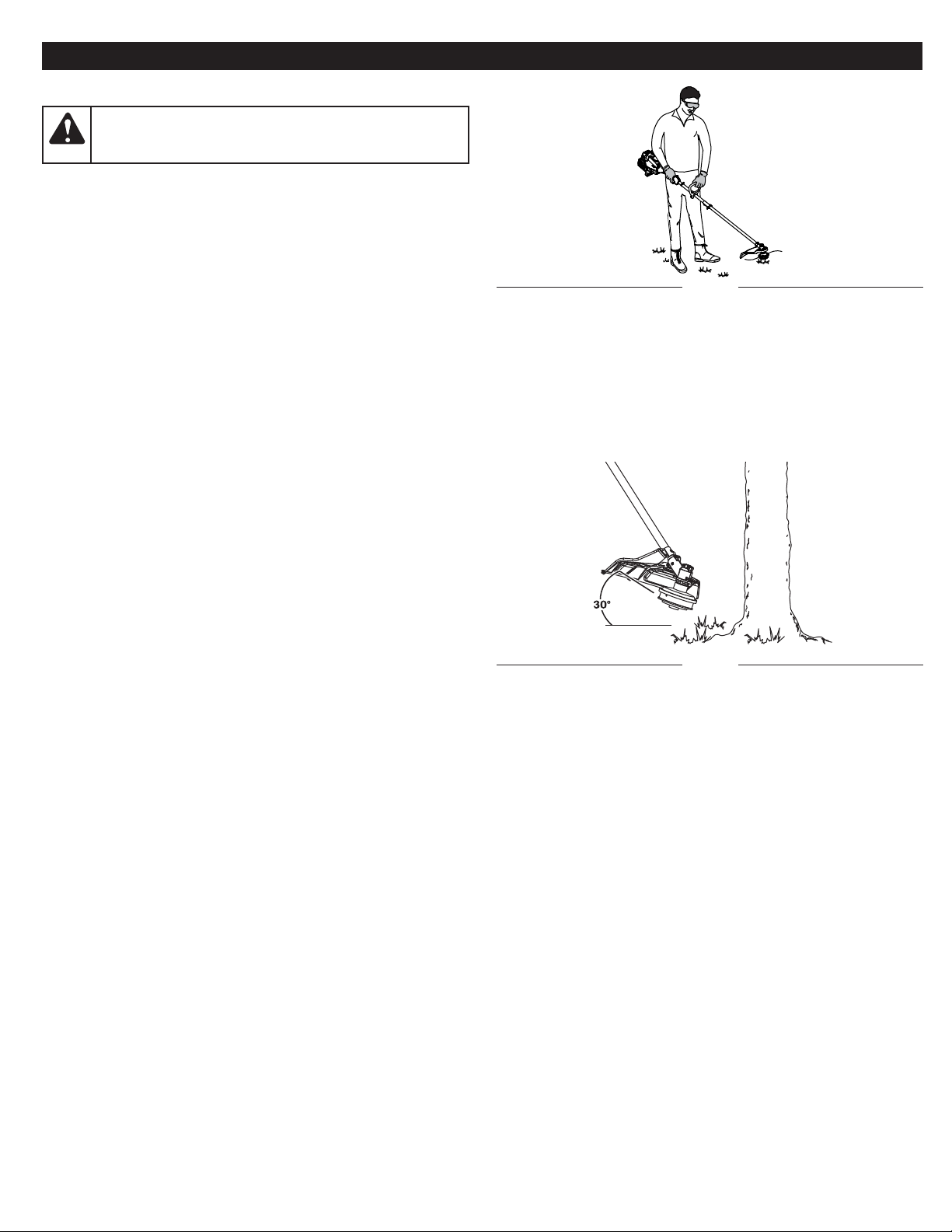
HOLDING THE UNIT
• Stand in the operating position (Fig. 10).
• Hold the shaft grip with the right hand. Keep the right arm
slightly bent.
• Hold the handle with the left hand. Keep the left arm straight.
• Hold the unit at waist level.
• Keep the cutting head parallel to the ground so that it easily
contacts the grass without the need for bending over.
WARNING:
Always wear eye, hearing, hand, foot and
body protection to reduce the risk of injury when operating
this unit.
TIPS FOR BEST RESULTS
• Keep the cutting head parallel to the ground.
• Cut from left to right whenever possible. This improves the unit's
cutting efficiency and throws clippings away from the operator.
• Do not trim wet grass or weeds.
NOTE: Some line breakage will occur from:
• Entanglement with foreign matter
• Normal line fatigue
• Attempting to cut thick vegetation
• Forcing the line into objects such as walls or fence posts
DECORATIVE TRIMMING
When trimming around trees, posts, fences, etc., rotate the whole
unit so that the cutting head is at a 30° angle to the ground (Fig. 11).
Fig. 10
Fig. 11
Page 11
11
MAINTENANCE SCHEDULE
Perform these required maintenance procedures at the frequency
stated in the table. These procedures should also be a part of any
seasonal tune-up.
NOTE: Some maintenance procedures may require special tools or
skills. If you are unsure about these procedures, take the unit to
an MTD authorized service dealer.
NOTE: Maintenance, replacement, or repair of the emission control
devices and system may be performed by an MTD authorized
service dealer.
NOTE: Please read the California/EPA statement that came with the
unit for a complete listing of terms and coverage for the emissions
control devices, such as the spark arrestor, muffler, carburetor, etc.
WARNING:
To prevent serious injury, never perform
maintenance or repairs while the unit is running. Always
allow the unit to cool before servicing or repairing the unit.
Disconnect the spark plug wire to prevent the unit from
starting accidentally.
MAINTENANCE
FREQUENCY MAINTENANCE REQUIRED
Every 10 hours • Clean and re-oil the air filter. Refer to
Maintaining the Air Filter.
Every 25 hours • Check the spark plug condition and gap.
Refer to Maintaining the Spark Plug.
Fig. 12
Fig. 13
Fig. 14
Line
Holes
Cutting Head
Positioning
Tunnel
Positioning
Tunnel
Line
Line
Fig. 15
Line
Line
Cutting Head
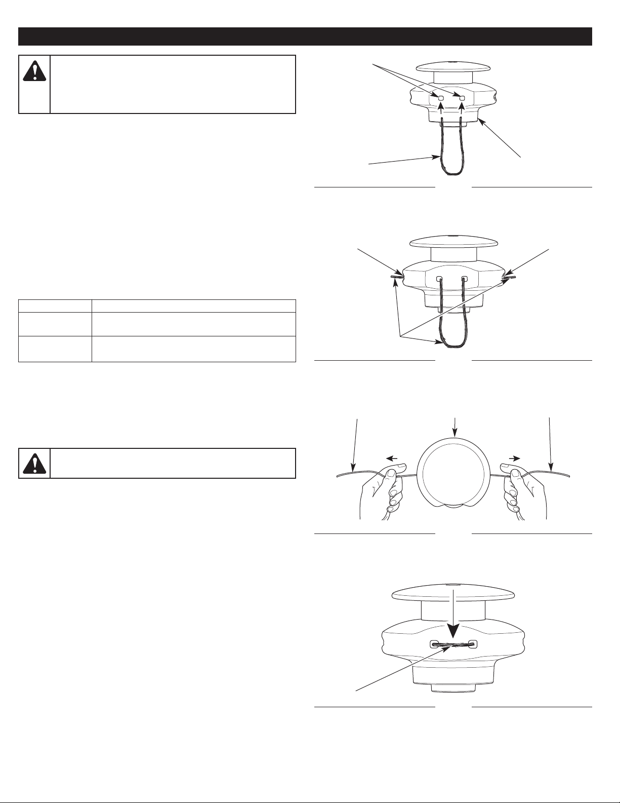
REPLACING THE TRIMMING LINE
Only use the trimming line described in the Specifications section.
Other types of trimming line may cause the engine to overheat or fail.
1. Remove the old line from the cutting head.
2. Use a clean cloth to clean the surface of the cutting head.
3. Insert the ends of the line through the circular holes in the side
of the cutting head (Fig. 12). Push the line through the holes until
both ends protrude from the positioning tunnels (Fig. 13).
4. Pull the ends of the line until the line is tight against the cutting
head. Make sure the ends of the line are of equal length (Fig. 14).
If one end is longer than the other, push the longer end back
through the cutting head partway and pull the shorter end out. If
necessary, repeat this process until both ends are of equal length.
5. Press the exposed trimming line between the circular holes until
it lies flat against the cutting head (Fig. 15).
WARNING:
Never use metal-reinforced line, wire, chain or
rope. These can break off and become dangerous projectiles.
Page 12
12
MAINTAINING THE AIR FILTER
Failure to maintain the air filter can result in poor performance or can
cause permanent damage to the engine. Engine failure due to
improper air filter maintenance is not covered by the product warranty.
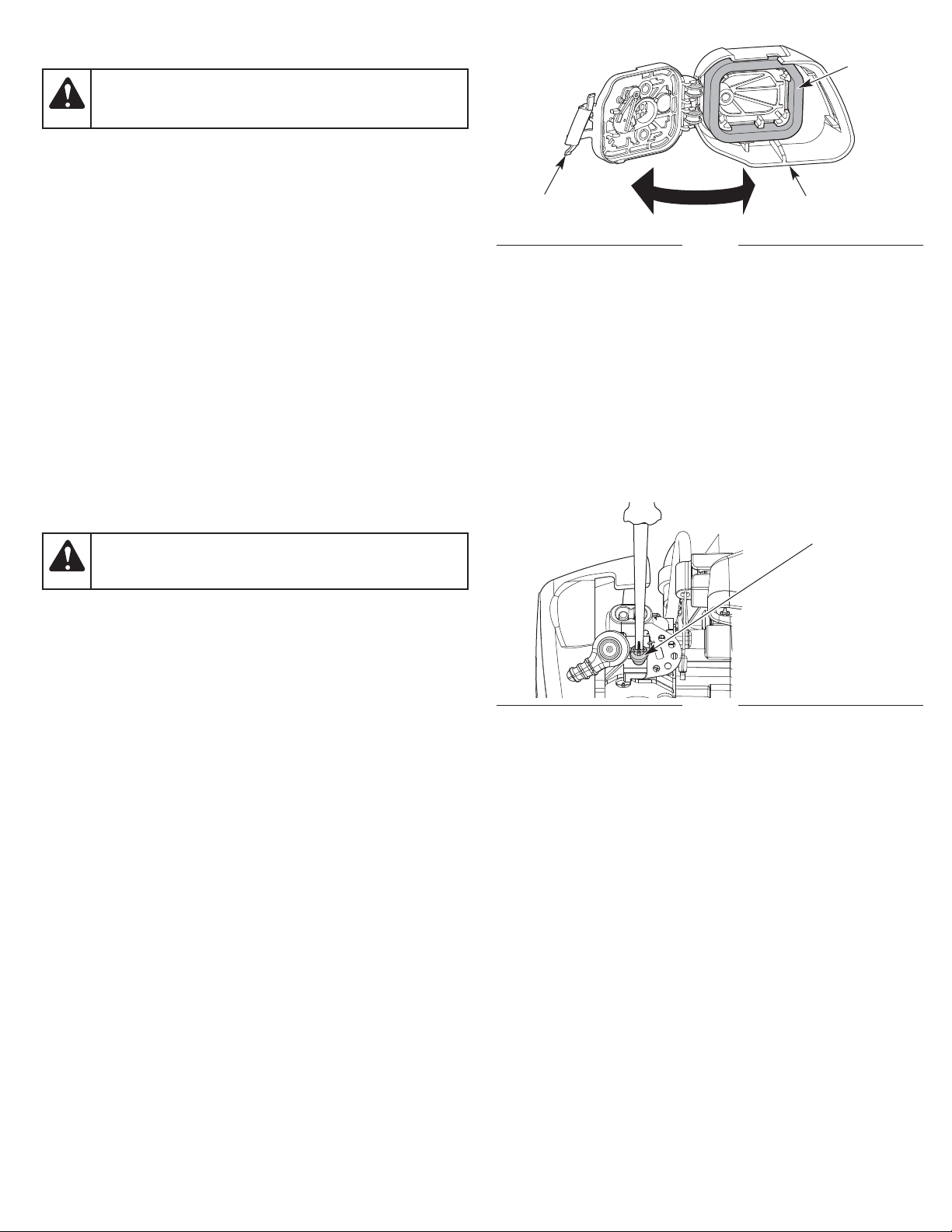
Cleaning the Air Filter
1. Open the air filter cover: press in the lock tab and swing the air
filter cover to the right (Fig. 16).
2. Remove the air filter from inside the air filter cover (Fig. 16).
3. Wash the air filter in detergent and water. Rinse the air filter
thoroughly and allow it to dry.
4. Lightly coat the air filter with clean SAE 30 oil.
5. Squeeze the air filter to spread and remove excess oil.
6. Reinstall the air filter inside the air filter cover (Fig. 16).
NOTE: Operating the unit without the air filter and air filter cover will
VOID the warranty.
7. Close the air filter cover: swing the air filter cover to the left and
press it closed until the lock tab snaps into place (Fig. 16).
WARNING:
To avoid serious personal injury, always stop
the engine and allow it to cool before cleaning or maintaining
the unit.
Fig. 16
Air Filter
Air Filter Cover
Lock Tab
ADJUSTING THE IDLE SPEED
NOTE: Careless adjustments can seriously damage the unit. A qualified
service dealer should make carburetor adjustments.
If, after checking the fuel and cleaning the air filter, the engine still
will not idle, adjust the idle speed screw as follows:
1. Start the engine. Refer to Starting and Stopping.
2. Release the throttle control and let the engine idle. If the engine
stops, use a small Phillips screwdriver to turn the idle speed screw
clockwise, 1/8 of a turn at a time (as needed) until the engine idles
smoothly (Fig. 17).
3. If the engine is idling too quickly, turn the idle speed screw
counterclockwise, 1/8 of a turn at a time (as needed) to reduce the
idle speed (Fig. 17).
Checking the fuel, cleaning the air filter, and adjusting the idle speed
should solve most engine problems. If not, and any of the following
conditions are true, take the unit to a qualified service dealer:
• the engine will not idle
• the engine hesitates or stalls on acceleration
• there is a loss of engine power
WARNING:
The cutting head may spin during idle speed
adjustments. Wear protective clothing and observe all
safety instructions to prevent serious personal injury.
Fig. 17
Idle Speed Screw
Page 13

13
Fig. 18
0.025 in.
(0.635 mm)
MAINTAINING THE SPARK PLUG
1. Stop the engine and allow it to cool. Grasp the spark plug boot
firmly and pull it from the spark plug.
2. Clean around the spark plug. Remove the spark plug from the
cylinder head with a 5/8-inch socket, turning counterclockwise.
3. Inspect the spark plug. If the spark plug is cracked, fouled or
dirty, replace it with a replacement part #753-06193, a
Champion RDJ7J or an equivalent spark plug.
4. Use a feeler gauge to set the air gap at 0.025 in. (0.635 mm)
(Fig. 18).
5. Install the spark plug in the cylinder head. Tighten the spark plug
with a 5/8-inch socket, turning it clockwise until snug.
NOTE: If using a torque wrench, torque to:
110-120 in.•lb. (12.3-13.5 N•m). Do not over tighten.
6. Reattach the spark plug boot.
WARNING:
Do not sand blast, scrape or clean spark plug
electrodes. Grit in the engine could damage the cylinder.
Page 14

14
CLEANING AND STORAGE
CLEANING
Use a small brush to clean the outside of the unit. Do not use strong
detergents. Household cleaners that contain aromatic oils such as
pine and lemon, and solvents such as kerosene, can damage
plastic. Wipe off any moisture with a soft cloth.
STORAGE
• Never store a fueled unit where fumes may reach an open flame
or spark.
• Allow the engine to cool before storing.
• Lock up the unit to prevent unauthorized use or damage.
• Store the unit in a dry, well-ventilated area.
• Store the unit out of the reach of children.
Short-term Storage (1-2 weeks)
1. Store the unit in a horizontal position. If this is not possible, store
the unit vertically with the engine at the top.
Long-term Storage
1. Remove the fuel cap, tip the unit and drain the fuel into an
approved container. Reinstall the fuel cap.
2. Start the engine and allow it to run until it stalls. This ensures
that all fuel has been drained from the carburetor.
3. Allow the engine to cool. Remove the spark plug and put 5
drops of any high quality motor oil or 2-cycle oil into the cylinder.
Pull the starter rope slowly to distribute the oil. Reinstall the
spark plug.
4. Thoroughly clean the unit and inspect it for any loose or
damaged parts. Repair or replace damaged parts and tighten
loose screws, nuts or bolts.
Preparing the Unit for Use after Long-term Storage
1. Remove the spark plug and drain all of the oil from the cylinder.
NOTE: Do not use fuel that has been stored for more than 30 days.
Dispose of old fuel according to federal, state and local regulations.
WARNING:
To avoid serious personal injury, always stop
the engine and allow it to cool before cleaning or maintaining
the unit.
Page 15

15
If further assistance is required, contact an authorized service dealer.
The fuel tank is empty Fill the fuel tank with properly mixed fuel
The primer bulb was not pressed enough Press the primer bulb 10 times or until fuel is visible
The engine is flooded
Squeeze the throttle control and pull the starter rope until the engine
starts
The fuel is old (over 30 days) and/or improperly mixed Drain the fuel tank and add fresh, properly mixed fuel
The spark plug is fouled Replace the spark plug
TROUBLESHOOTING
The fuel is old (over 30 days) and/or improperly mixed Drain the fuel tank and add fresh, properly mixed fuel
The cutting head is bound with grass Stop the engine and clean the cutting head
The air filter is dirty Clean or replace the air filter
PROBLEM SOLUTION
The air filter is dirty Clean or replace the air filter
The fuel is old (over 30 days) and/or improperly mixed Drain the fuel tank and add fresh, properly mixed fuel
The idle speed is incorrect Adjust the idle speed
The fuel is old (over 30 days) and/or improperly mixed Drain the fuel tank and add fresh, properly mixed fuel
The air filter is dirty Clean or replace the air filter
The spark plug is fouled Replace the spark plug
THE ENGINE WILL NOT START
THE ENGINE WILL NOT IDLE
THE ENGINE WILL NOT ACCELERATE
THE ENGINE LACKS POWER OR STALLS
Page 16

16
The limited warranty set forth below is given by MTD LLC (MTD) with respect to new merchandise purchased and used in the United States,
its possessions and territories.
MTD warrants this product against defects in material and workmanship for a period of two (2) years commencing on the date of original
purchase and will, at its option, repair or replace, free of charge, any part found to be defective in material or workmanship. This limited
warranty shall only apply if this product has been operated and maintained in accordance with the Operator’s Manual furnished with the
product, and has not been subject to misuse, abuse, commercial use, neglect, accident, improper maintenance, alteration, vandalism, theft,
fire, water or damage because of other peril or natural disaster. Damage resulting from the installation or use of any accessory or attachment
not approved by MTD for use with the product(s) covered by this manual will void your warranty as to any resulting damage. This warranty is
limited to ninety (90) days from the date of original retail purchase for any MTD product that is used for rental or commercial purposes, or
any other income-producing purpose.
HOW TO OBTAIN SERVICE: Warranty service is available, WITH PROOF OF PURCHASE THROUGH YOUR LOCAL AUTHORIZED SERVICE
DEALER. To locate the dealer in your area, visit our website at www.mtdproducts.com or www.mtdproducts.ca, check for a listing in the
Yellow Pages, call 1-800-800-7310 or 1-800-668-1238 in Canada, or write to P.O. Box 361131, Cleveland, OH 44136-0019. No product returned
directly to the factory will be accepted unless prior written permission has been extended by the Customer Service Department of MTD.
This limited warranty does not provide coverage in the following cases:
A. Tune-ups - Spark Plugs, Carburetor Adjustments, Filters
B. Wear items - Bump Knobs, Outer Spools, Cutting Line, Inner Reels, Starter Pulley, Starter Ropes, Drive Belts, Saw Chains, Guide Bars,
Cultivator Tines, Blades.
C. MTD does not extend any warranty for products sold or exported outside of the United States of America, its possessions and territories,
except those sold through MTD’s authorized channels of export distribution.
MTD reserves the right to change or improve the design of any MTD Product without assuming any obligation to modify any product
previously manufactured.
No implied warranty, including any implied warranty of merchantability or fitness for a particular purpose, applies after the
applicable period of express written warranty above as to the parts as identified. No other express warranty or guaranty, whether
written or oral, except as mentioned above, given by any person or entity, including a dealer or retailer, with respect to any product
shall bind MTD. During the period of the Warranty, the exclusive remedy is repair or replacement of the product as set forth above.
(Some states do not allow limitations on how long an implied warranty lasts, so the above limitation may not apply to you.)
The provisions as set forth in this Warranty provide the sole and exclusive remedy arising from the sales. MTD shall not be liable for
incidental or consequential loss or damages including, without limitation, expenses incurred for substitute or replacement lawn
care services, for transportation or for related expenses, or for rental expenses to temporarily replace a warranted product. (Some
states do not allow limitations on how long an implied warranty lasts, so the above limitation may not apply to you.)
In no event shall recovery of any kind be greater than the amount of the purchase price of the product sold. Alteration of the safety features
of the product shall void this Warranty. You assume the risk and liability for loss, damage, or injury to you and your property and/or to others
and their property arising out of the use or misuse or inability to use the product.
This limited warranty shall not extend to anyone other than the original purchaser, original lessee or the person for whom it was purchased
as a gift.
How State Law Relates to this Warranty: This warranty gives you specific legal rights, and you may also have other rights which vary from
state to state.
To locate your nearest service dealer, dial 1-800-800-7310 in the United States or 1-800-668-1238 in Canada.
MTD LLC
P.O. Box 361131
Cleveland, OH 44136-0019
MANUFACTURER’S LIMITED WARRANTY FOR:
Page 17

769-08353 / 00 08/12
Manuel de l’opérateur
Taille-bordure à 2 temps
TABLE DES MATIÈRES
Service technique . . . . . . . . . . . . . . . . . . . . . . . . . . . . . . . . . . . . .17
Sécurité . . . . . . . . . . . . . . . . . . . . . . . . . . . . . . . . . . . . . . . . . . . . .18
Apprenez à connaître votre appareil . . . . . . . . . . . . . . . . . . . . . . .21
Caractéristiques . . . . . . . . . . . . . . . . . . . . . . . . . . . . . . . . . . . . . .21
Assemblage . . . . . . . . . . . . . . . . . . . . . . . . . . . . . . . . . . . . . . . . . .22
Huile et carburant . . . . . . . . . . . . . . . . . . . . . . . . . . . . . . . . . . . . .24
Mise en marche et arrêt . . . . . . . . . . . . . . . . . . . . . . . . . . . . . . . .25
Utilisation . . . . . . . . . . . . . . . . . . . . . . . . . . . . . . . . . . . . . . . . . . . .26
Entretien . . . . . . . . . . . . . . . . . . . . . . . . . . . . . . . . . . . . . . . . . . . .27
Nettoyage et entreposage . . . . . . . . . . . . . . . . . . . . . . . . . . . . . . .30
Dépannage . . . . . . . . . . . . . . . . . . . . . . . . . . . . . . . . . . . . . . . . . .31
Garantie . . . . . . . . . . . . . . . . . . . . . . . . . . . . . . . . . . . . . . . . . . . . .32
Toutes les informations, illustrations et caractéristiques contenues
dans ce manuel reposent sur les dernières informations disponibles
sur ce produit à la date d’impression. Nous nous réservons le droit
d’apporter à tout instant des modifications, sans préavis.
Copyright© 2012 MTD SOUTHWEST INC, Tous droits réservés.
NE RAMENEZ PAS CET APPAREIL CHEZ LE
REVENDEUR. UNE PREUVE D’ACHAT SERA EXIGÉE
POUR AVOIR RECOURS À LA GARANTIE.
Pour obtenir de l’aide concernant l’assemblage, les commandes,
l’utilisation ou l’entretien de cet appareil, veuillez contacter le service
à la clientèle au 1-800-800-7310 (États-Unis) ou au 1-800-668-1238
(Canada). Pour obtenir des informations supplémentaires sur cet
appareil, visitez le site Internet : www.mtdproducts.com (É.-U.) ou
www.mtdproducts.ca (Canada).
Pour profiter du service technique, veuillez appeler le service à la
clientèle pour obtenir une liste des centres de réparation agréés les
plus proches. Les réparations de cet appareil doivent être confiées
uniquement à un centre de réparation agréé, à la fois pendant et
après la période de garantie. Lors d’une réparation, utilisez
uniquement des pièces de rechange identiques.
CONSERVEZ CES INSTRUCTIONS
SERVICE TECHNIQUE
Page 18

18
SÉCURITÉ
NOTE SUR LE PARE-ÉTINCELLES
REMARQUE : à l’intention des utilisateurs sur les terrains
forestiers américains et dans les États de Californie, du Maine,
de l’Oregon et de Washington. Tous les services des forêts
américains et les États de Californie (codes des ressources
publiques 4442 et 4443), de l’Oregon et de Washington exigent, au
titre de la loi, que certains moteurs à combustion interne utilisés
dans les broussailles de forêt et/ou les zones recouvertes d’herbe
soient équipés d’un pare-étincelles, soient maintenus en bon état
de marche, ou soient construits, équipés et entretenus en vue
d’éviter tout risque d’incendie. Veuillez contacter les autorités
nationales ou locales pour connaître les réglementations à cet
égard. Le non-respect de ces exigences pourrait impliquer votre
responsabilité ou entraîner une amende. Cet appareil est équipé
en usine d’un pare-étincelles. Si ce dernier doit être remplacé,
veuillez consulter votre CENTRE DE RÉPARATION LOCAL pour
installer le pot d’échappement réf. 753-06418.
Veuillez lire le manuel de l’opérateur et respecter tous les
avertissements et consignes de sécurité. Dans le cas contraire,
l’opérateur et/ou les passants peuvent subir des blessures graves.
SYMBOLE SIGNIFICATION
AVERTISSEMENT :
indique un danger GRAVE.
Le non-respect d’un symbole d’AVERTISSEMENT PEUT
provoquer des blessures graves de l’opérateur ou d’autres
personnes.
ATTENTION :
indique un danger MODÉRÉ.
Le non-respect d’un symbole ATTENTION POURRAIT
provoquer des blessures ou des dommages des biens de
l’opérateur ou d’autres personnes.
Les symboles de sécurité visent à attirer votre attention sur les
dangers éventuels. Vous devez accorder une attention particulière
aux symboles de sécurité afin de bien les comprendre. Les
avertissements de sécurité n’éliminent pas les dangers en euxmêmes. Les instructions ou mises en garde ne remplacent en rien
les mesures de prévention appropriées contre les accidents.
REMARQUE : vous donne des informations ou des consignes
essentielles pour l’utilisation ou l’entretien de l’équipement.
DANGER :
indique un danger EXTRÊME.
Le non-respect d’un symbole de DANGER ENTRAÎNERA
des blessures graves, voire un décès, de l’opérateur ou
d’autres personnes.
PROPOSITION 65 DE L’ÉTAT DE CALIFORNIE
AVERTISSEMENT :
les gaz d’échappement, certains
de leurs constituants et certains composants finis
contiennent ou émettent des produits chimiques reconnus
par l’État de Californie comme étant à l’origine de cancers
ou de malformations congénitales ou autres dangers pour
la reproduction. Lavez-vous les mains après avoir
manipulé l’appareil.
Page 19

19
VEUILLEZ LIRE TOUTES LES INSTRUCTIONS AVANT
• Veuillez lire soigneusement ces instructions. Familiarisez-vous
avec les commandes et l’utilisation correcte de l’appareil.
• N’utilisez pas cet appareil quand vous êtes fatigué, malade ou sous
l’influence de boissons alcoolisées, de drogues ou de médicaments.
• Les enfants ne doivent pas utiliser cet appareil. Les adolescents
doivent être supervisés par des adultes.
• Tous les carters et dispositifs de sécurité doivent être
correctement installés avant l’utilisation de cet appareil.
• Inspectez l’appareil avant l’utilisation. Remplacez les pièces
endommagées. Détectez les fuites de carburant éventuelles.
Assurez-vous que toutes les fixations sont en place et bien
serrées. Remplacez les pièces fissurées, ébréchées ou
endommagées d’une manière ou d’une autre. N’utilisez pas
l’appareil quand des pièces sont desserrées ou endommagées.
• Utilisez uniquement le fil de coupe décrit dans la section
Caractéristiques de ce manuel. N’utilisez jamais de fils, de
câbles, de chaînes ou de cordons à renfort métallique. Ils
peuvent se casser et se transformer en projectiles dangereux.
• Vous devez être conscient des risques de blessures à la tête,
aux mains et aux pieds.
• Inspectez attentivement la zone de travail avant de démarrer
l’appareil. Retirez les pierres, le verre cassé, les clous, les fils, les
ficelles et autres objets qui peuvent être projetés ou s’enrouler
dans l’appareil.
• Éloignez les enfants, les passants et les animaux domestiques ;
ils doivent rester dans un rayon d’au moins 15 mètres (50 pieds).
Même à cette distance, il existe néanmoins un risque de
projectiles pour les personnes à proximité. Encouragez-les à
porter des lunettes de sécurité. Si quelqu’un s’approche de
vous, arrêtez immédiatement l’appareil.
• Appuyez sur la manette des gaz et vérifiez qu’elle revient
automatiquement à la position de ralenti. Effectuez tous les
réglages ou réparations avant d’utiliser l’appareil.
PENDANT L’UTILISATION
• Portez des lunettes de sécurité conformes aux normes ANSI Z87.1
en vigueur et marquées comme telles. Portez une protection
auditive pendant l’utilisation de cet appareil. Portez un écran facial
ou un masque antipoussières si la tâche est poussiéreuse.
• Portez un pantalon long et épais, des bottes, des gants et une
chemise à manches longues. Ne portez pas des vêtements
amples, des bijoux, un pantalon court, des sandales et ne travaillez
pas pieds nus. Attachez vos cheveux au-dessus des épaules.
• Le carter de la tête de coupe doit toujours être en place pendant
l’utilisation de l’appareil. N’utilisez pas l’appareil sans que les
deux fils de coupe soient tendus et que le fil correct soit installé.
Ne tirez pas le fil de coupe au-delà du carter de protection.
• Cet appareil est doté d'un embrayage. La tête de coupe reste
immobile quand le moteur tourne au ralenti. Si ce n'est pas le
cas, apporter l'appareil à un centre de réparation agréé pour
obtenir un ajustement.
• Réglez la poignée afin d’avoir la meilleure prise en main.
• Assurez-vous que la tête de coupe n’est pas en contact avec
tout autre élément avant de démarrer l’appareil.
• Utilisez l’appareil uniquement en plein jour ou avec un bon
éclairage artificiel.
• Évitez tout démarrage accidentel. Placez-vous dans la position de
démarrage dès que vous tirez sur le câble de démarreur. L’opérateur
et l’appareil doivent être dans une position stable pendant le
démarrage. Consultez les sections Mise en marche et Arrêt.
• Utilisez le bon outil. Utilisez uniquement cet outil pour l’usage prévu.
• Tenez toujours l’appareil à deux mains lorsqu’il est en marche.
Tenez fermement les deux anses ou poignées.
• Ne vous penchez pas trop en avant. Conservez toujours une
position stable et un bon équilibre. Montrez-vous très prudent
quand vous travaillez sur des pentes raides.
• Éloignez vos mains, votre visage et vos pieds des pièces
mobiles. Ne touchez pas ou n’essayez pas d’arrêter des pièces
en mouvement.
• Ne touchez pas le moteur, le carter d’engrenage ou le pot
d’échappement. Ces composants deviennent extrêmement
chauds pendant l’utilisation, même après l’arrêt de l’appareil.
• N’utilisez pas l’appareil à une vitesse supérieure à celle
nécessaire pour réaliser le travail. Ne faites pas fonctionner
l’appareil à haute vitesse quand vous ne l’utilisez pas.
• Ne forcez pas l’appareil. Il sera plus efficace et plus sûr si vous
l’utilisez à la vitesse pour laquelle il a été conçu.
• Arrêtez toujours l’appareil quand le travail est interrompu ou
quand vous vous déplacez d'un endroit à un autre.
• Si vous heurtez ou enroulez un objet étranger dans l’appareil,
arrêtez immédiatement l’appareil et vérifiez les dommages
éventuels. Ne redémarrez pas l’appareil avant de l’avoir réparé.
N’utilisez pas l’appareil quand des pièces sont desserrées ou
endommagées.
• Arrêtez le moteur et débranchez la bougie pour les tâches
d’entretien ou les réparations.
AVERTISSEMENTS DE SÉCURITÉ POUR LES APPAREILS
À GAZ
• Stockez le carburant uniquement dans des récipients
spécifiquement conçus à cet usage et approuvés pour le
stockage de telles substances.
• Arrêtez toujours le moteur et laissez-le refroidir avant de remplir
le réservoir d’essence. N’enlevez jamais le bouchon du réservoir
de carburant ou ne remplissez jamais ce dernier quand le
moteur est chaud. Dévissez toujours lentement le bouchon du
réservoir de carburant afin de relâcher toute pression présente
avant de le remplir.
• Mélangez et ajoutez toujours le carburant dans une zone
extérieure propre et bien aérée, en l’absence totale d’étincelles
ou de flammes. NE fumez PAS.
• N’utilisez jamais l’appareil quand le bouchon du réservoir de
carburant n’est pas correctement vissé.
• CONSIGNES DE SÉCURITÉ IMPORTANTES •
AVERTISSEMENT :
quand vous utilisez l’appareil,
vous devez respecter toutes les règles de sécurité. Veuillez
lire ces consignes avant d’utiliser l’appareil pour assurer la
sécurité de l’opérateur et de tous les passants. Veuillez
conserver ces instructions pour référence ultérieure.
AVERTISSEMENT : l’essence est extrêmement
inflammable et ses vapeurs peuvent exploser en présence
d’une source d’inflammation. Prenez les précautions
suivantes :
• Évitez de créer une source d’inflammation en présence d’un
déversement de carburant. Essuyez immédiatement tout carburant
échappé du réservoir avant de démarrer l’appareil. Éloignez
l’appareil à 9,1 mètres (30 pieds) au moins de la source de
ravitaillement et du site avant de démarrer le moteur. NE fumez PAS.
• Ne démarrez jamais ou n’utilisez jamais l’appareil à l’intérieur
d’un espace ou d’un bâtiment clos. L’inhalation des fumées
d’échappement peut tuer. Utilisez cet appareil uniquement dans
une zone extérieure bien aérée.
Page 20

20
• SYMBOLES DE SÉCURITÉ ET INTERNATIONAUX •
Le présent manuel de l’opérateur décrit les symboles et pictogrammes de sécurité et internationaux, susceptibles d’apparaître sur ce
produit. Veuillez lire le manuel de l’opérateur pour connaître les informations complètes sur la sécurité, l’assemblage, l’utilisation, l’entretien
et la réparation.
SYMBOLE SIGNIFICATION SYMBOLE SIGNIFICATION
• SYMBOLE D’ALERTE DE SÉCURITÉ
Indique un danger, un avertissement ou une mise en
garde. Peut être utilisé conjointement avec d’autres
symboles ou pictogrammes.
• LISEZ LE MANUEL DE L’OPÉRATEUR
AVERTISSEMENT : veuillez lire le(s) manuel(s) de
l’opérateur et respecter tous les avertissements et
consignes de sécurité. Dans le cas contraire,
l’opérateur et/ou les passants peuvent subir des
blessures graves.
• PORTEZ DES PROTECTIONS AUDITIVES ET
OCULAIRES
AVERTISSEMENT : la projection d’objets et les
bruits forts peuvent provoquer des blessures oculaires
graves et une perte auditive. Portez une protection
oculaire conforme aux normes ANSI Z87.1 en vigueur,
ainsi qu’une protection auditive pendant l’utilisation
de cet appareil. Utilisez un écran facial complet dès
que nécessaire.
• ESSENCE SANS PLOMB
Utilisez toujours de l’essence sans plomb, propre et
neuve.
• HUILE
Consultez le manuel de l’opérateur pour connaître le
type d’huile à utiliser.
• N’UTILISEZ PAS UN CARBURANT E85 DANS CET
APPAREIL
AVERTISSEMENT : il a été prouvé qu’un carburant
contenant plus de 10 % d’éthanol est susceptible
d’endommager ce moteur et d’annuler la garantie.
• COMMANDE DE MARCHE/ARRÊT
ALLUMAGE / DÉMARRAGE / MARCHE
• COMMANDE DE MARCHE/ARRÊT
ARRÊT
• POIRE D’AMORÇAGE
Poussez complètement et lentement la poire
d’amorçage à 10 reprises.
• LES OBJETS PROJETÉS ET LA TÊTE ROTATIVE
PEUVENT PROVOQUER DES BLESSURES GRAVES
AVERTISSEMENT : les petits objets peuvent être
propulsés à des vitesses élevées, provoquant des
blessures. Tenez-les à l’écart du rotor en mouvement.
• ÉLOIGNEZ LES PASSANTS
AVERTISSEMENT : éloignez tous les passants,
en particulier les enfants et les animaux domestiques,
à 15 m (50 pieds) au moins de la zone de coupe.
• SURFACE CHAUDE
AVERTISSEMENT : ne touchez pas un pot
d’échappement ou un cylindre chaud. Vous pourriez
vous brûler. Ces éléments chauffent énormément
lorsque l’appareil est en marche. Ils restent chauds
pendant un court instant après l’arrêt.
• LAME TRANCHANTE
AVERTISSEMENT : lame tranchante sur le carter de
protection de l’accessoire de coupe. Pour éviter toute
blessure grave, ne touchez pas la lame du coupe-fil.
AUTRES AVERTISSEMENTS DE SÉCURITÉ
• Toutes les procédures d’entretien, autres que celles décrites
dans ce manuel, doivent être réalisées par un revendeur agréé.
• Avant une inspection, un entretien, un nettoyage, un entreposage,
un transport ou le remplacement d’une pièce de l’appareil :
1. Arrêtez l’appareil.
2. Assurez-vous que toutes les pièces mobiles se sont arrêtées.
3. Laissez l’appareil refroidir.
4. Débranchez le fil de la bougie.
• Assurez-vous que l’appareil est sécurisé pour les transports.
• Quand le réservoir contient du carburant, ne rangez jamais
l’appareil à l’intérieur d’un bâtiment où des vapeurs d’essence
pourraient atteindre une flamme nue (veilleuses, etc.) ou des
étincelles (interrupteurs, moteurs électriques, etc.).
• Rangez l’appareil dans un endroit sec et sûr ou en hauteur pour
éviter une utilisation non autorisée ou des dommages. Gardez
toujours l’appareil hors de portée des enfants.
• Ne mouillez pas ou n’éclaboussez pas l’appareil avec de l’eau ou
tout autre liquide. Les poignées doivent rester sèches, propres et
dépourvues de tout dépôt. Nettoyez l’appareil après chaque
utilisation. Consultez la section Nettoyage et entreposage.
• Conservez ces instructions. Consultez-les souvent et utilisez-les
pour former d’autres utilisateurs. Si vous prêtez cet appareil à
d’autres personnes, remettez-leur également ces instructions.
CONSERVEZ CES INSTRUCTIONS
• Utilisez uniquement des pièces et des accessoires de rechange
du fabricant d’origine pour cet appareil. Ils sont disponibles
auprès de votre centre de réparation agréé. L’utilisation d’autres
pièces ou accessoires pourrait entraîner de graves blessures de
l’utilisateur ou endommager l’appareil, et annuler la garantie.
• L’appareil doit rester propre. Retirez avec précaution la végétation
et autres débris qui pourraient bloquer les pièces mobiles.
• Pour réduire les risques d’incendie, remplacez un pot
d’échappement et un pare-étincelles défectueux. Nettoyez l’herbe,
les feuilles, les couches de graisse excessives ou les dépôts de
carbone présents sur le moteur et le pot d’échappement.
• Si l’appareil commence à vibrer de façon anormale, arrêtez-le
immédiatement. Inspectez l’appareil pour découvrir l’origine des
vibrations. Les vibrations indiquent en général un problème.
Page 21

Carter de protection de
la tête de coupe
Bouchon du
réservoir de
carburant
Poignée
Tête de coupe
Poignée d’arbre
Tube de l’arbre
Poignée du câble
de démarreur
Manette
des gaz
Bougie
Pot d’échappement
Interrupteur Marche/Arrêt
Lame du coupe-fil
Couvercle
du filtre à air
Coupleur
Poire
d’amorçage
Levier
d’étrangleur
21
APPRENEZ À CONNAÎTRE VOTRE APPAREIL
APPLICATIONS
Utilisation comme taille-bordure :
• Coupe d’herbe et de mauvaises herbes.
• Coupe de bordures
• aille décorative autour des arbres, des clôtures, etc.
D’autres accessoires facultatifs peuvent être utilisés avec cet appareil.
CARACTÉRISTIQUES*
* Toutes les caractéristiques reposent sur les dernières informations disponibles sur le produit au moment de l’impression de ce manuel.
Nous nous réservons le droit d’apporter à tout instant des modifications, sans préavis.
Type de moteur. . . . . . . . . . . . . . . . . . . . . . . . . . . . . . . . . . . . . . . . . . . . . . . . . . . . . . . . . . . . . . . . . . . . . . . . . . . . . . . . . Refroidi par air, 2 tempse
Cylindrée . . . . . . . . . . . . . . . . . . . . . . . . . . . . . . . . . . . . . . . . . . . . . . . . . . . . . . . . . . . . . . . . . . . . . . . . . . . . . . . . . . . . . . . . 25 cc (1,52 po. cube)
Écartement des électrodes . . . . . . . . . . . . . . . . . . . . . . . . . . . . . . . . . . . . . . . . . . . . . . . . . . . . . . . . . . . . . . . . . . . . . . . . . . 0,635 mm (0,025 po.)
Bougie. . . . . . . . . . . . . . . . . . . . . . . . . . . . . . . . . . . . . . . . . . . . . . . . . . . . . . . . . . . . . . . . . . . . . . . . . . . . . . . . . Champion® RDJ7J ou équivalent
Lubrification. . . . . . . . . . . . . . . . . . . . . . . . . . . . . . . . . . . . . . . . . . . . . . . . . . . . . . . . . . . . . . . . . . . . . . . . . . . . . . . . . . . . Mélange carburant/huile
Rapport carburant/huile . . . . . . . . . . . . . . . . . . . . . . . . . . . . . . . . . . . . . . . . . . . . . . . . . . . . . . . . . . . . . . . . . . . . . . . . . . . . . . . . . . . . . . . . . . 40:1
Capacité du réservoir de carburant . . . . . . . . . . . . . . . . . . . . . . . . . . . . . . . . . . . . . . . . . . . . . . . . . . . . . . . . . . . . . . . . . . . . . . . . . 296 ml (10 oz.)
Poids approximatif de l’appareil (sans carburant, avec tête de coupe, carter de protection et poignée) . . . . . . . . . . . . 4,5 - 5 kg (10 - 11 livres)
Mécanisme de coupe . . . . . . . . . . . . . . . . . . . . . . . . . . . . . . . . . . . . . . . . . . . . . . . . . . . . . . . . . . . . . . . . . . . . . . . . Tête de coupe de lignes fixes
Découpe de ligne . . . . . . . . . . . . . . . . . . . . . . . . . . . . . . . . . . . . . . . . . . . . . . . . . . . . . . . . . . . . . . . . . . . . . . Fil précoupé de 2,41 mm (0,095 po)
Diamètre de la trajectoire de coupe . . . . . . . . . . . . . . . . . . . . . . . . . . . . . . . . . . . . . . . . . . . . . . . . . . . . . . . . . . . . . . . . . . . . . . . 35,56 cm (14 po.)
AUCUN OUTIL NÉCESSAIRE POUR
L'ASSEMBLAGE :
• Tournevis à tête cruciforme #2
• Douille de 9,50 mm (3/8 po)
Page 22

22
ASSEMBLAGE
INSTALLATION ET RÉGLAGE DE LA POIGNÉE
Installation de la poignée
1. Poussez la poignée sur le tube de l’arbre (Fig. 2). L'orifice du
boulon dans la poignée doit se trouver à droite.
2. Insérer le boulon dans l'orifice du boulon et le pousser à travers
(Fig. 2). Serrer le boulon avec une douille de 9,50 mm (3/8 po),
mais ne pas le serrer complètement.
3. Tout en tenant l’appareil en position d’utilisation (Fig. 10),
déplacez la poignée à la hauteur vous assurant la meilleure prise
en main. Placez-la à 15,24 cm (6 po.) au moins de l’extrémité de
la poignée d’arbre (Fig. 2).
4. Serrer le boulon avec une douille de 9,50 mm (3/8 po) jusqu'à ce
que la poignée soit bien sécurisée.
Réglage de la poignée
Si la poignée doit être ajustée :
1. Desserrer le boulon avec une douille de 9,50 mm (3/8 po) (Fig. 2).
2. Tout en tenant l’appareil en position d’utilisation (Fig. 10),
déplacez la poignée à la hauteur vous assurant la meilleure prise
en main. Placez-la à 15,24 cm (6 po.) au moins de l’extrémité de
la poignée d’arbre (Fig. 2).
3. Serrer le boulon avec une douille de 9,50 mm (3/8 po) jusqu'à ce
que la poignée soit bien sécurisée.
INSTALLATION DU CARTER DE PROTECTION DE LA
TÊTE DE COUPE
Suivez les instructions suivantes si le carter de protection n’est pas
installé. Suivez uniquement les instructions applicables au type
d’arbre et de carter dont cet appareil est équipé.
1. Placez le carter de protection de la tête de coupe sur le support
de fixation. Alignez les trous présents dans le carter de
protection de la tête de coupe avec ceux du support de fixation.
(Fig. 1)
2. Serrez manuellement les 2 vis, en les passant à travers le
support de fixation et le carter de protection.
3. À l’aide d’un tournevis à tête cruciforme #2, serrez les vis jusqu’à
ce que la tête de coupe soit correctement en place. Serrez les vis
uniformément. L’espace entre le support de fixation et le carter
de protection doit être identique des deux côtés.
Fig. 1
Support de
fixation
Carter de protection
de la tête de coupe
Vis (2)
AVERTISSEMENT :
pour éviter toute blessure grave,
n’utilisez jamais cet appareil quand le carter de protection
de la tête de coupe n’est pas en place.
Fig. 2
Boulon
Poignée
d’arbre
Minimum 15,24
cm (6 po.)
Poignée
Tube de
l’arbre
Page 23

23
Fig. 4
Fig. 5
Fig. 3
Bouton de déclenchement
Évidement de
guidage
Orifice de bordure à 90 °
(Tondeuse seulement)
Bouton
Trou primaire
Tube de l’arbre
inférieur
Tube de l’arbre
supérieur
UTILISATION DU COUPLEUR
Le coupleur permet l'utilisation de différents accessoires en option.
REMARQUE : pour faciliter l’installation ou le démontage de
l’accessoire, placez l’appareil sur le sol ou sur un établi.
Installation de l’accessoire
REMARQUE : retirez le chapeau de protection et l’entretoise grise
des arbres supérieur et inférieur afin de monter l’accessoire.
1. Tournez le bouton dans le sens horaire inverse pour le desserrer
(Fig. 3).
2. Tout en tenant fermement l’accessoire, poussez-le tout droit
dans le coupleur jusqu’à ce que le bouton de déclenchement
s’enclenche correctement dans le trou primaire (Fig. 5).
REMARQUE : l’alignement du bouton de déclenchement avec
l’évidement de guidage facilitera l’installation (Fig. 4).
3. Tournez le bouton dans le sens horaire pour le serrer (Fig. 3).
Pour une bordure décorative réalisée avec un accessoire taillebordures, verrouiller le bouton de déclenchement dans l'orifice de
bordure à 90 ° (Fig. 3).
Démontage de l’accessoire
1. Tournez le bouton dans le sens horaire inverse pour le desserrer
(Fig. 3).
2. Appuyez et maintenez enfoncé le bouton de déclenchement (Fig. 4).
3. Tout en tenant fermement le tube de l’arbre supérieur, tirez
l’accessoire en ligne droite pour le détacher du coupleur (Fig. 5).
AVERTISSEMENT :
Avant d'utiliser un accessoire, lire
et comprendre le manuel livré avec l'accessoire.
Respectez toutes les consignes de sécurité qu’il contient.
ATTENTION :
Avant d'utiliser l'appareil, s'assurer que le
bouton de déverrouillage est entièrement enclenché dans
l'orifice principal (Fig. 5) et que la poignée (Fig. 3) est bien
serrée.
AVERTISSEMENT :
pour éviter toute blesse grave ou
dommage, arrêtez l’appareil avant de démonter ou
d’installer un accessoire.
ATTENTION :
Le bouton de déclenchement doit être
enclenché dans l'orifice principal uniquement. L’utilisation
du mauvais orifice pourrait provoquer des blessures
graves ou endommager l’appareil.
Coupleur
Page 24

24
HUILE ET CARBURANT
REMPLISSAGE DU RÉSERVOIR
1. Placez l’appareil afin que le bouchon du réservoir soit tourné
vers le haut.
2. Dévissez le bouchon du réservoir.
3. Placez le bec verseur du bidon de carburant dans l’orifice de
remplissage du réservoir de l’appareil et remplissez ce dernier.
REMARQUE : ne remplissez pas le réservoir de manière excessive.
4. Essuyez la totalité du carburant échappé du réservoir.
5. Revissez le bouchon du réservoir.
6. Éloignez l’appareil à 9,1 mètres (30 pieds) au moins du bidon de
carburant et du site de ravitaillement avant de démarrer le moteur.
INSTRUCTIONS DE MÉLANGE D’HUILE ET DE
CARBURANT
L’utilisation d’un carburant vieux et/ou mal mélangé est la cause la
plus courante des problèmes de performance. Utilisez uniquement
une essence sans plomb neuve et propre. Respectez ces instructions
à la lettre pour mélanger correctement l’essence et l’huile.
Définition des carburants mélangés
Les carburants d’aujourd’hui sont souvent un mélange d’essence et
de produits oxygénés, comme l’éthanol, le méthanol ou l’éther
méthyl-tertiobutylique. Un carburant mélangé à l’alcool absorbe
l’eau. Il suffit de 1 % d’eau pour séparer le carburant et l’huile, ce
qui formera des acides pendant l’entreposage. Utilisez TOUJOURS
un carburant neuf (moins de 30 jours).
REMARQUE : jetez le vieux carburant en respectant les
réglementations fédérales, étatiques et locales.
Utilisation des carburants mélangés
Si vous utilisez un carburant mélangé :
• Utilisez toujours un mélange de carburant frais, comme
expliqué dans votre manuel de l’opérateur.
• Utilisez l’additif pour carburant STA-BIL® ou un produit équivalent
• Agitez toujours le mélange de carburant avant de remplir l’appareil
• Videz le réservoir et faites fonctionner le moteur jusqu’à
épuisement du carburant avant de ranger l’appareil
Utilisation d’additifs pour carburant
Le bidon d’huile pour moteur à 2 temps, qui est livré avec cet
appareil, contient un additif permettant d’empêcher la corrosion et
de minimiser la formation de résidus de gomme. Utilisez toujours la
marque d’huile pour moteur à 2 temps fournie avec cet appareil. En
cas d’indisponibilité, utilisez une huile conçue pour les moteurs à 2
temps refroidis par air, en la mélangeant avec un additif pour
carburant, comme le stabilisateur de carburant STA-BIL ou un
produit équivalent. Ajoutez 23 ml (2 oz.) d’additif pour 3,8 litres (1
gallon) de carburant selon les instructions du récipient. N’ajoutez
JAMAIS des additifs directement dans le réservoir de l’appareil.
AVERTISSEMENT :
l’essence est extrêmement
inflammable. Des vapeurs enflammées peuvent exploser.
Arrêtez toujours le moteur et laissez-le refroidir avant de
remplir le réservoir d’essence. Ne fumez pas pendant le
remplissage du réservoir. Maintenez toute flamme nue et
étincelle loin de la zone.
AVERTISSEMENT :
dévissez lentement le bouchon
du réservoir pour éviter toute blessure due à un jet de
carburant. N’utilisez jamais l’appareil quand le bouchon du
réservoir de carburant n’est pas correctement vissé.
AVERTISSEMENT : ajoutez l’essence dans une zone
extérieure propre et bien aérée. Essuyez immédiatement
tout carburant déversé. Évitez de créer une source
d’inflammation en présence d’un déversement de
carburant. Ne démarrez pas le moteur avant que les
vapeurs d’essence ne se soient dissipées.
AVERTISSEMENT :
N’UTILISEZ PAS UN CARBURANT
E85 DANS CET APPAREIL. Il a été prouvé qu’un carburant
contenant plus de 10 % d’éthanol est susceptible
d’endommager ce moteur et d’annuler la garantie.
Essence sans plomb Huile 2-temps
3,8 litres
(1 gallon américain)
95 ml
(3,2 oz.)
1 litre 25 ml
RAPPORT DE MÉLANGE - 40:1
Mélange du carburant
REMARQUE : cet appareil est livré avec un bidon d’huile pour
moteur à 2 temps de 95 ml (3,2 oz.). Pour obtenir le mélange de
carburant correct décrit ci-dessous, versez la totalité du bidon
dans 3,8 litres (1 gallon) d’essence sans plomb.
Mélangez soigneusement l’essence sans plomb et l’huile pour
moteur à 2 temps en respectant à la lettre les proportions. Ne les
mélangez pas directement dans le réservoir de l’appareil. Utilisez un
bidon séparé. Utilisez un rapport d’essence/huile de 40:1. Consultez
le tableau ci-dessous pour connaître les rapports de mélange
exacts de l’essence et de l’huile.
ATTENTION :
pour que le moteur fonctionne
correctement en toute fiabilité, suivez scrupuleusement les
instructions de mélange de l’essence et de l’huile
indiquées sur le bidon d’huile pour moteur à 2 temps.
L’utilisation d’un carburant mal mélangé peut gravement
endommager le moteur.
Page 25

25
MISE EN MARCHE ET ARRÊT
AVERTISSEMENT :
utilisez cet appareil uniquement
dans une zone extérieure bien aérée. Des émanations de
monoxyde de carbone dans un endroit confiné peuvent
être mortelles.
AVERTISSEMENT :
évitez tout démarrage accidentel
de l’appareil. Pour éviter toute blessure grave, l’opérateur
et l’appareil doivent être tous deux en position stable
quand l’opérateur tire sur le câble de démarreur (Fig. 9).
INSTRUCTIONS DE DÉMARRAGE
1. Mélangez l’essence et l’huile. Consultez les instructions de
mélange de l’huile et de l’essence.
2. Remplissez le réservoir d’essence. Consultez la section
Remplissage du réservoir.
REMARQUE : il n’est pas nécessaire de démarrer l’appareil.
L’interrupteur de marche/arrêt est constamment en position de
marche (I) (Fig. 6).
3. Appuyez lentement et relâchez la poire d’amorçage à 10
reprises (Fig. 7). Si aucune quantité de carburant n’apparaît
dans la poire d’amorçage, appuyez et relâchez la poire jusqu’à
l’apparition de carburant.
4. Retourner le levier d'étrangleur dans le sens horaire jusqu'à ce
qu'il s'enclenche (Fig. 8).
5. Accroupissez-vous en position de démarrage (Fig. 9).
6. NE PAS enfoncer la manette des gaz (Fig. 6). Tirer sur la corde
de démarrage en effectuant un mouvement contrôlé et ferme
jusqu'à ce que l'appareil démarre (Fig. 9).
7. Laisser tourner le moteur pendant 5 à 10 secondes. Si l'appareil
s'arrête pendant ce temps, appuyer sur la manette des gaz et
tirer sur le cordon du démarreur en effectuant un mouvement
contrôlé et ferme jusqu'à ce que l'appareil démarre.
8. Serrer et maintenir la manette des gaz enfoncée. Laissez le
moteur chauffer pendant 30 à 60 secondes.
REMARQUE : le moteur a correctement chauffé quand il accélère
sans hésitation.
SI... le moteur ne démarre pas, reprenez la procédure de démarrage
à l’étape 3.
SI... l'appareil est chaud et ne démarre pas en 3 tractions du cordon
de démarrage, appuyer sur la manette des gaz et tirer sur le
cordon de démarrage en effectuant un mouvement contrôlé et
ferme jusqu'à ce que l'appareil démarre.
INSTRUCTIONS D’ARRÊT
1. Relâchez la manette des gaz et laissez le moteur tourner au ralenti.
2. Appuyez sur l’interrupteur de marche/arrêt et maintenez-le
enfoncé en position d’arrêt (O) jusqu’à ce que le moteur s’arrête
complètement (Fig. 6).
Fig. 6
Fig. 9
Marche (I)
Arrêt (O)
Manette des gaz
Position de
démarrage
Poignée du câble
de démarreur
Fig. 7
Poire
d’amorçage
Fig. 8
Levier d’étrangleur
Page 26

26
UTILISATION
TENUE DE L’APPAREIL
• Placez-vous en position d’utilisation (Fig. 10).
• Tenez la poignée d’arbre avec la main droite. Le bras droit doit
rester légèrement plié.
• Tenez la poignée avec la main gauche. Le bras gauche doit
rester tendu.
• Tenez l’appareil au niveau de votre taille.
• La tête de coupe doit rester parallèle au sol afin de toucher
facilement l’herbe sans que l’opérateur ne soit obligé de se pencher.
AVERTISSEMENT :
portez toujours une protection
pour les yeux, les oreilles, les mains, les pieds et le corps
afin de limiter les risques de blessure pendant l’utilisation
de cet appareil.
CONSEILS POUR UN RÉSULTAT OPTIMAL
• Maintenez la tête de coupe parallèle au sol.
• Coupez dès que possible de la gauche vers la droite. L’efficacité
de la coupe est ainsi améliorée et les coupures de végétation
sont projetées loin de l’opérateur.
• Ne coupez pas de l’herbe ou des mauvaises herbes mouillées.
REMARQUE : le fil peut parfois se casser à cause de :
• Une matière étrangère qui s’enroule dans l’appareil
• Une usure normale du fil
• La coupe d’une végétation épaisse
• Le forçage du fil contre des objets comme des murs ou des
poteaux de clôture
COUPE DE BORDURE DÉCORATIVE
Quand vous taillez autour des arbres, des poteaux, des clôtures,
etc., faites tourner complètement l’appareil afin que la tête de
coupe soit à un angle de 30° par rapport au sol (Fig. 11).
Fig. 10
Fig. 11
Page 27

27
PROGRAMME D’ENTRETIEN
Effectuez ces procédures d’entretien obligatoires aux intervalles
indiqués dans le tableau. Ces procédures doivent également faire
partie d’une mise au point saisonnière.
REMARQUE : certaines procédures d’entretien peuvent nécessiter
des compétences ou des outils particuliers. Si vous avez des
doutes concernant ces procédures, amenez l’appareil chez un
revendeur agréé de MTD.
REMARQUE : l’entretien, le remplacement ou la réparation du
système et des dispositifs de contrôle des émissions peuvent être
réalisés par un revendeur agréé de MTD.
REMARQUE : veuillez lire la déclaration de l’État de Californie /
EPA (agence de protection de l’environnement) qui est livrée
avec l’appareil pour obtenir une liste complète des conditions et
de la couverture des dispositifs antipollution, tels que le pareétincelles, le pot d’échappement, le carburateur, etc.
AVERTISSEMENT :
pour éviter des blessures graves,
n’effectuez jamais des travaux d’entretien ou des
réparations quand l’appareil est en marche. Laissez
toujours l’appareil refroidir avant un entretien ou une
réparation. Débranchez le fil de la bougie pour éviter un
démarrage accidentel de l’appareil.
ENTRETIEN
INTERVALLE D’ENTRETIEN OBLIGATOIRE
Toutes les 10
heures
• Nettoyez et graissez le filtre à air. Consultez
la section Entretien du filtre à air.
Toutes les 25
heures
• Vérifiez l’état de la bougie et l’écartement
des électrodes. Consultez la section
Entretien de la bougie.
Fig. 12
Fig. 13
Fig. 14
Fil
Orifices
Tête de coupe
Tunnel de
positionnement
Tunnel de
positionnement
Fil
Fil
Fig. 15
Fil
Fil
Tête de coupe
REMPLACEMENT DU FIL DE COUPE
Utilisez uniquement le fil de coupe décrit dans la section
Caractéristiques. D’autres types de fils peuvent provoquer une
surchauffe ou une panne du moteur.
1. Enlever l'ancien fil de la tête de coupe.
2. Utiliser un chiffon propre pour nettoyer la surface de la tête de
coupe.
3. Insérer les extrémités du fil à travers les orifices circulaires du
côté de la tête de coupe (Fig. 12). Pousser le fil dans les orifices
jusqu'à ce que les deux extrémités fassent saillie des tunnels de
positionnement (Fig. 13).
4. Tirer sur les extrémités du fil jusqu'à ce qu'il soit bien serré contre
la tête de coupe. S'assurer les extrémités du fil soient de longueur
égale (Fig. 14). Si une extrémité est plus longue que l'autre,
pousser l'extrémité arrière à mi-course à travers la tête de coupe
et tirer sur la partie courte. Si nécessaire, répéter cette opération
jusqu'à ce que les deux extrémités soient de longueur égale.
5. Appuyer sur le fil de coupe exposé entre les orifices circulaires
jusqu'à ce qu'il repose à plat contre la tête de coupe (Fig. 15).
AVERTISSEMENT :
n’utilisez jamais de fils, de câbles,
de chaînes ou de cordons à renfort métallique. Ils peuvent
se casser et se transformer en projectiles dangereux.
Page 28

28
ENTRETIEN DU FILTRE À AIR
Le non-entretien du filtre à air peut entraîner une mauvaise
performance ou des dommages permanents du moteur. Une panne
de moteur découlant d’un mauvais entretien du filtre à air n’est pas
couverte par la garantie du produit.
Nettoyage du filtre à air
1. Ouvrez le couvercle du filtre à air : appuyez sur la patte de
verrouillage et faites basculer le couvercle du filtre vers la droite
(Fig. 16).
2. Retirez le filtre à air de l’intérieur du couvercle du filtre (Fig. 16).
3. Nettoyez le filtre à air avec de l’eau et du détergent. Rincez le
filtre soigneusement et laissez-le sécher.
4. Appliquez une légère couche d’huile SAE 30 propre sur le filtre à air.
5. Pressez le filtre à air pour répartir et éliminer l’excès d’huile.
6. Réinstallez le filtre à air à l’intérieur du couvercle (Fig. 16).
REMARQUE : toute utilisation de l’appareil en l’absence du filtre à
air et de son couvercle ANNULERA la garantie.
7. Fermez le couvercle du filtre à air : basculez le couvercle du filtre
vers la gauche et appuyez dessus jusqu’à ce que la patte de
verrouillage s’enclenche en position fermée (Fig. 16).
AVERTISSEMENT :
pour éviter toute blessure grave,
arrêtez toujours le moteur et laissez-le refroidir avant de
nettoyer ou de procéder à un entretien de l’appareil.
Fig. 16
Filtre à air
Couvercle du filtre à air
Patte de
verrouillage
RÉGLAGE DU RALENTI
REMARQUE : un réglage négligé peut gravement endommager
l’appareil. Un centre de réparation qualifié doit procéder au
réglage du carburateur.
Si le moteur ne se met toujours pas au ralenti après une vérification
du carburant et un nettoyage du filtre à air, réglez la vis du ralenti
comme suit :
1. Démarrez le moteur. Consultez les sections Mise en marche et Arrêt.
2. Relâchez la manette des gaz et laissez le moteur tourner au
ralenti. Si le moteur s’arrête, insérez un petit tournevis à pointe
cruciforme pour tourner la vis du ralenti dans le sens horaire, de
1/8 de tour à la fois (comme nécessaire) jusqu’à ce que le
moteur tourne au ralenti (Fig. 17).
3. Si le ralenti du moteur est trop rapide, tournez la vis de réglage
du ralenti dans le sens horaire inverse, de 1/8 de tour à la fois
(comme nécessaire) pour réduire le régime du ralenti (Fig. 17).
La vérification du carburant, le nettoyage du filtre à air et le réglage
du ralenti devraient résoudre la plupart des problèmes de moteur.
Dans le cas contraire et si l’une des conditions suivantes se produit,
faites régler l’appareil dans un centre de réparation qualifié :
• le moteur ne se met pas au ralenti
• le moteur hésite ou cale lors d’une accélération
• le moteur perd de sa puissance
AVERTISSEMENT :
la tête de coupe peut tourner
pendant le réglage du ralenti. Portez des vêtements de
protection et respectez toutes les consignes de sécurité
pour éviter toute blessure grave.
Fig. 17
Vis de réglage du ralenti
Page 29

29
Fig. 18
0,635 mm
(0,025 po.)
ENTRETIEN DE LA BOUGIE
1. Arrêtez le moteur et laissez-le refroidir. Saisissez fermement le
chapeau de la bougie et retirez-le de la bougie.
2. Nettoyez tout autour de la bougie. Retirez la bougie de la
culasse avec une douille de 16 mm (5/8 po.), en tournant dans le
sens horaire inverse.
3. Inspectez la bougie. Si la bougie est fissurée ou encrassée,
remplacez-la par une pièce de rechange n°753-06193, une
bougie Champion RDJ7J ou équivalent.
4. Utilisez une jauge d’épaisseur pour régler l’écartement à 0,635
mm (0,025 po.) (Fig. 18).
5. Installez la bougie dans la culasse. Serrez la bougie avec une
douille de 16 mm (5/8 po.) en tournant dans le sens horaire
jusqu’à ce qu’elle soit juste serrée.
REMARQUE : si vous utilisez une clé dynamométrique, serrez à :
12,3-13,5 N•m (110-120 po.•livre). Ne serrez pas de manière
excessive.
6. Refixez le chapeau de la bougie.
AVERTISSEMENT :
ne sablez pas, ne grattez pas ou ne
nettoyez pas les électrodes de la bougie. La présence de
grenailles dans le moteur pourrait endommager le cylindre.
Page 30

30
NETTOYAGE ET ENTREPOSAGE
NETTOYAGE
Utilisez une petite brosse pour nettoyer la partie externe de
l’appareil. N’utilisez pas un détergent fort. Les produits ménagers
contenant des huiles aromatiques, comme le pin et le citron, et les
solvants comme le kérosène peuvent endommager le plastique.
Essuyez toute trace d’humidité avec un chiffon doux.
ENTREPOSAGE
• Ne rangez jamais l’appareil quand le réservoir contient encore
de l’essence dont les vapeurs pourraient entrer en contact avec
une flamme nue ou une étincelle.
• Laissez le moteur refroidir avant de ranger l’appareil.
• Rangez l’unité dans un endroit fermé à clé pour éviter toute
utilisation non autorisée ou tout dommage.
• Rangez l’unité dans un endroit sec et bien aéré.
• Rangez l’appareil hors de portée des enfants.
Entreposage à court terme (1-2 semaines)
1. Rangez l’unité en position horizontale. En cas d’impossibilité,
rangez l’appareil à la verticale, le moteur étant au sommet.
Entreposage de longue durée
1. Retirez le bouchon du réservoir d’essence, basculez l’appareil et
vidangez le carburant dans un bidon approprié. Revissez le
bouchon du réservoir.
2. Démarrez le moteur et laissez-le tourner jusqu’à ce qu’il cale.
Ainsi, le carburateur sera totalement vidé de tout carburant.
3. Laissez le moteur refroidir. Retirez la bougie et versez dans le
cylindre 5 gouttes d’une huile de moteur de haute qualité ou
d’une huile pour moteur à 2 temps. Tirez lentement sur le câble
de démarreur pour répartir l’huile. Réinstallez la bougie.
4. Nettoyez soigneusement l’appareil et vérifiez la présence de
pièces desserrées ou endommagées. Réparez ou remplacez les
éléments endommagés, et serrez les vis, les écrous ou les
boulons desserrés.
Préparation de l’appareil après un entreposage de longue durée
1. Retirez la bougie et vidangez la totalité de l’huile présente dans
le cylindre.
REMARQUE : n’utilisez pas un carburant qui a été entreposé
pendant plus de 30 jours. Jetez le vieux carburant en respectant
les réglementations fédérales, étatiques et locales.
AVERTISSEMENT :
pour éviter toute blessure grave,
arrêtez toujours le moteur et laissez-le refroidir avant de
nettoyer ou de procéder à un entretien de l’appareil.
Page 31

31
Si vous avez besoin d’une aide supplémentaire, veuillez contacter un revendeur agréé.
Le réservoir de carburant est vide Remplissez le réservoir avec un carburant correctement mélangé
La poire d’amorçage n’a pas été comprimée suffisamment Appuyez sur la poire à 10 reprises ou jusqu’à l’apparition du carburant
Le moteur est noyé
Appuyer sur la manette des gaz et tirer sur le cordon du démarreur
jusqu'à ce que l'appareil démarre.
Le carburant est vieux (plus de 30 jours) et/ou mal mélangé Vidangez le réservoir et ajoutez un mélange de carburant correct et neuf
La bougie est encrassée Remplacez la bougie
DÉPANNAGE
Le carburant est vieux (plus de 30 jours) et/ou mal mélangé Vidangez le réservoir et ajoutez un mélange de carburant correct et neuf
La tête de coupe est engorgée d’herbe Arrêtez le moteur et nettoyez la tête de coupe
Le filtre à air est sale Nettoyez ou remplacez le filtre à air
PROBLÈME SOLUTION
Le filtre à air est sale Nettoyez ou remplacez le filtre à air
Le carburant est vieux (plus de 30 jours) et/ou mal mélangé Vidangez le réservoir et ajoutez un mélange de carburant correct et neuf
Le ralenti est mal réglé Réglez le ralenti
Le carburant est vieux (plus de 30 jours) et/ou mal mélangé Vidangez le réservoir et ajoutez un mélange de carburant correct et neuf
Le filtre à air est sale Nettoyez ou remplacez le filtre à air
La bougie est encrassée Remplacez la bougie
LE MOTEUR NE DÉMARRE PAS
LE MOTEUR NE SE MET PAS AU RALENTI
LE MOTEUR N’ACCÉLÈRE PAS
LE MOTEUR MANQUE DE PUISSANCE OU CALE
Page 32

32
La garantie limitée énoncée ci-après est accordée par MTD LLC (« MTD ») et s’applique aux produits neufs achetés et utilisés aux ÉtatsUnis, ses possessions et territoires.
MTD garantit ce produit contre tout défaut de pièces et de main d’œuvre pendant une période de deux (2) ans à compter de la date d’achat
initiale et s’engage à titre gratuit à réparer ou à remplacer, à sa discrétion, toute pièce présentant un défaut de pièces et de main d’œuvre.
Cette garantie limitée s’applique uniquement si le produit a été utilisé et entretenu conformément aux instructions du manuel de l’opérateur
livré avec le produit, et qu’il n’a pas fait l’objet d’une utilisation inadéquate, abusive, commerciale ou négligente, d’un accident, d’un
entretien inapproprié, d’une modification, d’un acte de vandalisme, d’un vol, d’un incendie, d’une inondation ou d’un dommage découlant
d’une catastrophe naturelle ou autre. Tout dommage découlant de l’installation ou de l’utilisation d’une pièce ou d’un accessoire non
approuvé par MTD avec le(s) produit(s) couvert(s) dans le présent manuel annulera la garantie quant aux dommages qui en résulteraient. La
présente garantie est limitée à quatre-vingt-dix (90) jours à compter de la date d’achat initiale d’un produit MTD utilisé à des fins locatives ou
commerciales, ou toute utilisation produisant des revenus.
OBTENTION DU SERVICE DE GARANTIE : le service de garantie est disponible SUR PRÉSENTATION D’UNE PREUVE D’ACHAT AUPRES
DE VOTRE CENTRE DE RÉPARATION LOCAL AGREE. Pour trouver le revendeur le plus proche, visitez notre site Internet sur
www.mtdproducts.com ou www.mtdproducts.ca, consultez les pages jaunes, téléphonez au 1-800-800-7310 ou 1-800-668-1238 au
Canada, ou adressez un courrier à P.O. Box 361131, Cleveland, OH 44136-0019. Aucun produit retourné directement à l’usine ne sera
accepté si le service à la clientèle de MTD n’a pas accordé une autorisation préalable et écrite au client.
Cette garantie limitée ne s’applique pas dans les cas suivants :
A. Mises au point : bougies, réglages du carburateur, filtres
B. Éléments d’usure : boutons de butée, bobines extérieures, fil de coupe, moulinets, poulie du démarreur, câbles de démarreur, courroies
d’entraînement, chaînes de scie, barres de guidage, couteaux de cultivateur, lames.
C. MTD n’accorde aucune garantie pour les produits vendus ou exportés des États-Unis d’Amérique, ses possessions et territoires, à
l’exception des produits vendus par le biais du réseau agréé de distribution à l’exportation de MTD.
MTD se réserve le droit de modifier ou d’améliorer la conception de ses produits sans pour autant assumer l’obligation de modifier tout
produit de fabrication plus ancienne.
Aucune garantie implicite, y compris toute garantie de qualité marchande ou d’adéquation à un usage particulier, n’est valable
après la période applicable de la garantie expresse et écrite ci-dessus concernant les pièces qui sont identifiées. Aucune autre
garantie expresse, écrite ou orale, à l’exception de celle mentionnée ci-dessus, accordée par toute personne ou entité, y compris
un revendeur ou un distributeur, concernant tout produit ne peut engager MTD. Pendant la période de garantie, l’unique recours est
la réparation ou le remplacement du produit dans les conditions énoncées ci-dessus. (Certains états n’autorisent pas la limitation de la
durée d’une garantie implicite ; de ce fait, les limitations ci-dessus peuvent ne pas vous concerner.)
Les dispositions énoncées dans la présente garantie constituent le recours unique et exclusif inhérent à la vente. MTD ne sera pas
tenu responsable des pertes ou dommages accessoires ou indirects, y compris sans aucune limite, les dépenses découlant de
l’utilisation de services de remplacement ou de substitution pour l’entretien de votre pelouse, du transport ou des dépenses
associées, ou de la location permettant le remplacement temporaire d’un produit garanti. (Certains états n’autorisent pas la limitation
de la durée d’une garantie implicite ; de ce fait, les limitations ci-dessus peuvent ne pas vous concerner.)
Aucun recouvrement de quelque nature qu’il soit ne pourra dépasser le prix d’achat du produit vendu. Toute modification des dispositifs de
sécurité du produit annulera cette garantie. Vous assumez le risque et la responsabilité résultant d’une perte, d’un dommage ou d’un
préjudice que vous et vos biens et /ou que d’autres personnes et leurs biens pourront encourir du fait de l’utilisation normale ou abusive ou
de l’incapacité à utiliser ce produit.
Cette garantie limitée ne doit en aucun cas inclure toute personne autre que l’acheteur d’origine, le preneur initial ou la personne à laquelle le
produit a été offert.
Rapport de cette garantie avec les lois de chaque état : la présente garantie vous confère certains droits juridiques spécifiques, et vous
pouvez bénéficier d’autres droits qui varient d’un état à l’autre.
Pour trouver le centre de réparation le plus proche, composez le 1-800-800-7310 aux États-Unis ou le 1-800-668-1238 au Canada.
MTD LLC
P.O. Box 361131
Cleveland, OH 44136-0019
GARANTIE LIMITÉE DU FABRICANT POUR :
Page 33

769-08353 / 00 08/12
Manual del Operador
ÍNDICE
Reparación y mantenimiento . . . . . . . . . . . . . . . . . . . . . . . . . . . .33
Seguridad . . . . . . . . . . . . . . . . . . . . . . . . . . . . . . . . . . . . . . . . . . .34
Conozca su unidad . . . . . . . . . . . . . . . . . . . . . . . . . . . . . . . . . . . .37
Especificaciones . . . . . . . . . . . . . . . . . . . . . . . . . . . . . . . . . . . . . .37
Montaje . . . . . . . . . . . . . . . . . . . . . . . . . . . . . . . . . . . . . . . . . . . . .38
Aceite y combustible . . . . . . . . . . . . . . . . . . . . . . . . . . . . . . . . . . .40
Arranque y detención . . . . . . . . . . . . . . . . . . . . . . . . . . . . . . . . . .41
Funcionamiento . . . . . . . . . . . . . . . . . . . . . . . . . . . . . . . . . . . . . . .42
Mantenimiento . . . . . . . . . . . . . . . . . . . . . . . . . . . . . . . . . . . . . . . .43
Limpieza y almacenamiento . . . . . . . . . . . . . . . . . . . . . . . . . . . . .46
Solución de Problemas . . . . . . . . . . . . . . . . . . . . . . . . . . . . . . . . .47
Garantía . . . . . . . . . . . . . . . . . . . . . . . . . . . . . . . . . . . . . . . . . . . . .48
Toda la información, las ilustraciones y las especificaciones que se
incluyen en el presente manual se basan en la información más
reciente sobre el producto disponible al momento de la impresión.
Nos reservamos el derecho a realizar cambios en cualquier
momento sin previo aviso.
Copyright© 2012 MTD SOUTHWEST INC, Todos los derechos
reservados.
NO DEVUELVA ESTA UNIDAD AL DISTRIBUIDOR. SE EXIGIRÁ
COMPROBANTE DE COMPRA PARA LAS REPARACIONES Y
EL MANTENIMIENTO QUE CUBRE LA GARANTÍA.
Por ayuda en relación con el montaje, los controles, el funcionamiento
o el mantenimiento de la unidad, llame al Departamento de Asistencia al
Cliente al 1-800-800-7310 en los Estados Unidos o al 1-800-668-1238
en Canadá.
Se puede encontrar información adicional sobre la
unidad en nuestro sitio web: www.mtdproducts.com (EE. UU.) o
www.mtdproducts.ca (Canadá).
Por reparaciones y mantenimiento, llame al Departamento de
Asistencia al Cliente a fin de obtener la lista de distribuidores de
servicio autorizados de su zona. La reparación y el mantenimiento
de la presente unidad, tanto dentro del período de la garantía como
después de él, sólo debe realizarlos un distribuidor de servicio
autorizado y aprobado. Cuando le dé servicio use únicamente
piezas de reemplazo idénticas.
GUARDE ESTAS INSTRUCCIONES
REPARACIÓN Y MANTENIMIENTO
Recortadora de 2 ciclos
Page 34

34
SEGURIDAD
NOTA SOBRE EL AMORTIGUADOR DE CHISPAS
NOTA: Para usuarios de los territorios de bosques de EE. UU. y
de los estados de California, Maine, Oregon y Washington.
Todos los territorios de bosques de EE. UU. y los estados de
California (Códigos de Recursos Públicos 4442 y 4443), Oregon y
Washington exigen por ley, que determinados motores de
combustión interna que se operan en zonas cubiertas por malezas
de bosque y/o hierbas cuenten con un amortiguador de chispas
que se deberá mantener en condiciones de uso adecuadas o que el
motor se diseñe, equipe y mantenga para prevenir incendios.
Corrobore con las autoridades estatales o locales cuáles son las
normativas correspondientes a dichas exigencias. El
incumplimiento de dichos requerimientos podría generarle una
responsabilidad o una multa. La presente unidad se equipa en la
fábrica con un amortiguador de chispas. Si debe reemplazarse,
pídale al DISTRIBUIDOR DE SERVICIO LOCAL que instale la Pieza
auxiliar n.° 753-06418 Conjunto del silenciador.
Lea el manual del operador y siga todas las advertencias e
instrucciones de seguridad. Si no lo hace, el operador y/o los
observadores pueden sufrir lesiones graves.
SÍMBOLOS SIGNIFICADO
ADVERTENCIA:
Indica un peligro GRAVE.
Si no se cumple una ADVERTENCIA de seguridad usted
mismo u otras personas PUEDEN sufrir lesiones graves.
PRECAUCIÓN:
Indica un peligro de GRAVEDAD
MODERADA.
Si no se cumple una señal de seguridad de PRECAUCIÓN
usted mismo o a otras personas PUEDEN sufrir lesiones o
se PUEDEN producir daños materiales.
El objetivo de los símbolos de seguridad es dirigir su atención hacia
posibles peligros. Los símbolos de seguridad, así como sus
explicaciones, necesitan su atención y comprensión completas. Las
advertencias de seguridad no eliminan por sí mismas ningún
peligro. Las instrucciones o advertencias que contienen no
reemplazan a las medidas adecuadas de prevención de accidentes.
NOTA: Proporciona información o instrucciones de vital importancia
para el funcionamiento o el mantenimiento del equipo.
PELIGRO:
Indica un peligro EXTREMO.
Si no se cumple una advertencia de seguridad de
PELIGRO usted mismo u otras personas sufrirán lesiones
graves o la muerte.
PROPOSICIÓN 65 DE CALIFORNIA
ADVERTENCIA:
El escape del motor de este producto,
algunos de sus componentes y algunos componentes
terminados contienen o liberan sustancias químicas que el
estado de California considera que pueden producir
cáncer, defectos de nacimiento u otros problemas
reproductivos. Lávese las manos después de estar en
contacto con estos componentes.
Page 35

35
LEA TODAS LAS INSTRUCCIONES ANTES DE USAR LA
UNIDAD
• Lea las instrucciones con atención. Debe familiarizarse con los
controles y con el uso apropiado de la unidad.
• No opere esta unidad si está cansado, enfermo o bajo la
influencia de alcohol, drogas o medicamentos.
• La unidad no debe ser utilizada por niños. Los adolescentes
deben contar con la compañía y guía de un adulto.
• Se deben instalar correctamente todos los protectores y
accesorios de seguridad antes de operar la unidad.
• Inspeccione la unidad antes de usarla. Reemplace las piezas
dañadas. Compruebe si hay pérdidas de combustible.
Compruebe que todas las sujeciones estén en su lugar y bien
ajustadas. Reemplace las piezas que estén agrietadas,
astilladas o dañadas de cualquier manera. No utilice la unidad si
hay piezas sueltas o dañadas.
• Use únicamente el hilo de recorte que se describe en la sección
Especificaciones de este manual. Nunca use un hilo, un cable,
una cadena o una cuerda de metal reforzados. Podrían
separarse y convertirse en proyectiles peligrosos.
• Tenga en cuenta el riesgo de lesiones en la cabeza, las manos y
los pies.
• Inspeccione el área con atención antes de arrancar la unidad.
Extraiga las rocas, los vidrios rotos, los clavos, los cables,
cordeles y demás objetos que podrían ser arrojados o enredarse
en la unidad.
• Despeje la zona de niños, observadores y mascotas;
manténgalos fuera de un radio de 50 pies (15 m), como mínimo.
Incluso a esa distancia, sigue el riesgo de ser alcanzados por
los objetos arrojados por el aire. Sugiérales a los observadores
que usen protección ocular. Si alguien se le aproxima, detenga
la unidad de inmediato.
• Apriete el control del acelerador y verifique que vuelva
automáticamente a la posición de ralentí. Realice todos los
ajustes o las reparaciones antes de usar la unidad.
DURANTE LA OPERACIÓN
• Utilice anteojos o antiparras de seguridad que cumplan con las
normas ANSI Z87.1 vigentes y que tengan la identificación
correspondiente. Utilice una protección auditiva al operar esta
unidad. Utilice una máscara facial o para polvos si la máquina
levanta polvo durante su funcionamiento.
• Use pantalones largos y gruesos, botas, guantes y camisa de
mangas largas. No use ropa holgada, alhajas, pantalones
cortos, sandalias ni ande descalzo. Sujétese el cabello a nivel de
los hombros.
• El protector del cabezal de corte siempre debe estar colocado
mientras se opera la unidad. No utilice la unidad si no están
extendidos ambos hilos de recorte y si no está instalado el hilo
adecuado. No extienda el hilo de recorte más allá de la longitud
del protector.
• Esta unidad tiene un embrague. El cabezal de corte permanece
fijo cuando el motor está en ralentí. Si no es así, debe llevar la
unidad a un distribuidor de servicio calificado para que la ajusten.
• Ajuste la manija para que brinde el mejor agarre.
• Compruebe que el cabezal de corte no esté en contacto con
nada antes de poner en marcha la unidad.
• Use la unidad solamente con luz de día o con una buena luz artificial.
• Evite arranques accidentales. Permanezca en la posición de
arranque siempre que tire de la cuerda de arranque. El operador
y la unidad deben estar en una posición estable durante el
arranque. Consulte Arranque y Parada
• Utilice la herramienta apropiada. Use esta herramienta sólo para
el propósito para el que fue diseñada.
• Sostenga siempre la unidad con ambas manos durante la
operación. Sostenga firmemente ambas manijas o empuñaduras.
• No se extienda demasiado. Siempre debe estar bien afirmado y
mantener el equilibrio adecuado. Tenga cuidado al trabajar en
pendientes o inclinaciones empinadas.
• Mantenga las manos, el rostro y los pies alejados de todas las
piezas móviles. No toque ni intente detener las piezas móviles.
• No toque el motor, el alojamiento del engranaje ni el silenciador.
Estas partes se ponen extremadamente calientes por el
funcionamiento, incluso después de que se apaga la unidad.
• No opere la unidad a una velocidad mayor a la necesaria para la
tarea. No haga funcionar la unidad a alta velocidad cuando no
está en uso.
• No exija demasiado a la unidad. Si se usa a la velocidad para la
que fue diseñada, realizará un trabajo más eficiente y seguro.
• Detenga siempre la unidad cuando la operación esté demorada
o cuando camine de un lugar a otro.
• Si golpea un objeto extraño o si éste se engancha en la unidad,
deténgala de inmediato y controle si se produjeron daños. No
utilice la unidad hasta haber reparado el daño. No utilice la
unidad si hay piezas sueltas o dañadas.
• Apague el motor y desconecte la bujía para realizar tareas de
mantenimiento o reparación.
ADVERTENCIAS DE SEGURIDAD PARA LAS UNIDADES
A GASOLINA
• Almacene el combustible únicamente en recipientes diseñados
específicamente y aprobados para el almacenamiento de dichos
materiales.
• Detenga siempre el motor y déjelo enfriar antes de llenar el
depósito. Nunca retire la tapa del depósito de combustible ni
agregue combustible cuando el motor esté caliente. Afloje siempre
lentamente la tapa del depósito de combustible para descargar la
presión que haya en el depósito antes de recargar combustible.
• Mezcle y agregue siempre combustible en una zona al aire libre,
limpia y bien ventilada, en la que no haya chispas ni llamas. NO
fume.
• Nunca opere la unidad si la tapa del combustible no está bien
sujeta en su lugar.
• INSTRUCCIONES DE SEGURIDAD IMPORTANTES •
ADVERTENCIA:
Se deben respetar todas las normas
de seguridad al usar la unidad. Por favor, lea estas
instrucciones antes de utilizar la unidad para garantizar la
seguridad del operador y los observadores. Por favor,
guarde estas instrucciones para su uso posterior.
ADVERTENCIA:
La gasolina es sumamente inflamable
y sus vapores pueden explotar si se encienden. Adopte las
siguientes precauciones:
• Evite que se genere una fuente de encendido para el
combustible derramado. Limpie de inmediato el combustible
derramado de la unidad, antes de encenderla. Mueva la unidad
al menos 30 pies (9.1m) de la fuente de combustible y del sitio
antes de arrancar el motor. NO fume.
• Nunca arranque ni use la unidad dentro de una habitación o de
una construcción cerrada. La inhalación de humos de escape
puede ser mortal. Opere esta unidad únicamente en una zona
bien ventilada, al aire libre.
Page 36

36
• SÍMBOLOS INTERNACIONALES Y DE SEGURIDAD •
Este manual del operador describe símbolos de seguridad e internacionales, así como pictogramas, que pueden aparecer en este producto.
Lea el manual del operador para obtener información completa sobre seguridad, montaje, funcionamiento, mantenimiento y reparaciones.
SÍMBOLOS SIGNIFICADO SÍMBOLOS SIGNIFICADO
• SÍMBOLO DE ALERTA DE SEGURIDAD
Indica peligro, advertencia o precaución. Puede
utilizarse junto con otros símbolos o pictogramas.
• LEA EL MANUAL DEL OPERADOR
ADVERTENCIA : Lea el (los) manual(es) del
operador y cumpla todas las advertencias e
instrucciones de seguridad. Si no lo hace, el operador
y/o los observadores pueden sufrir lesiones graves.
• UTILICE PROTECCIÓN OCULAR Y AUDITIVA
ADVERTENCIA: Los objetos que son arrojados
por el aire y los ruidos fuertes pueden provocar graves
lesiones oculares y pérdidas de audición. Cuando
opere esta unidad, utilice protección ocular que
cumpla con las normas ANSI Z87.1 vigentes y
protectores auditivos. Utilice una máscara que cubra
todo el rostro si es necesario.
• COMBUSTIBLE SIN PLOMO
Utilice siempre combustible limpio, nuevo y sin plomo.
• ACEITE
Consulte el manual del operador para conocer el tipo
adecuado de aceite.
• NO UTILICE COMBUSTIBLE E85 EN ESTA UNIDAD
ADVERTENCIA: Se ha demostrado que el
combustible que contiene más de un 10% de etanol
es probable que dañe este motor y anule la garantía.
• APAGADO/ENCENDIDO DE CONTROL DE PARADA
ENCENDIDO / ARRANQUE / MARCHA
• APAGADO/ENCENDIDO DE CONTROL DE PARADA
APAGADO o PARADA
• BULBO DEL CEBADOR
Presione por completo el bulbo del cebador
lentamente 10 veces.
• LOS OBJETOS QUE SON ARROJADOS POR EL
AIRE Y EL CORTADOR GIRATORIO PUEDEN
PROVOCAR LESIONES GRAVES
ADVERTENCIA: Es posible que se arrojen objetos
pequeños por el aire a alta velocidad, lo cual puede
provocar lesiones. Manténgase alejado del rotor giratorio.
• MANTENGA ALEJADOS A LOS OBSERVADORES
ADVERTENCIA: Mantenga a todos los
observadores, especialmente a los niños y las mascotas,
al menos a 50 pies (15 m) de la zona de trabajo.
• SUPERFICIE CALIENTE
ADVERTENCIA: No toque el silenciador o el
cilindro cuando estén calientes. Puede quemarse.
Estas piezas se calientan extremadamente durante el
funcionamiento. Una vez apagadas, continúan
calientes durante un período breve.
• CUCHILLA AFILADA
ADVERTENCIA: Hay una cuchilla afilada en el
protector del accesorio de recorte. A fin de evitar
lesiones graves, no toque la cuchilla de corte del hilo.
OTRAS ADVERTENCIAS DE SEGURIDAD
• Todas las tareas de reparación, con excepción de los
procedimientos de mantenimiento que se describen en este manual,
deben ser realizados por un distribuidor de servicio calificado.
• Use sólo piezas de reemplazo y accesorios del fabricante del
equipo original (OEM) para esta unidad. Los puede adquirir al
distribuidor de servicio autorizado. Si usa cualquier otra pieza o
accesorio, el usuario podría lesionarse gravemente o la unidad
podría dañarse y se anularía la garantía.
• Mantenga limpia la unidad. Quite con cuidado cualquier resto de
vegetación u otros residuos que puedan bloquear las piezas móviles.
• A fin de reducir el riesgo de incendio, reemplace el silenciador y
el amortiguador de chispas si están averiados. Mantenga el
motor y el silenciador libres de hierbas, hojas y de la
acumulación excesiva de grasa o de carbono.
• Si la unidad comienza a vibrar en forma anormal, deténgala de
inmediato. Inspeccione la unidad para determinar la causa de la
vibración. La vibración por lo general indica que hay algún problema.
• Antes de inspeccionar, limpiar, guardar o transportar la unidad, o
de hacer tareas de reparación o mantenimiento o reemplazar
alguna de sus piezas:
1. Detenga la unidad.
2. Asegúrese de que se hayan detenido todas las piezas móviles.
3. Deje que la unidad se enfríe.
4. Desconecte el cable de la bujía.
• Sujete la unidad durante el transporte.
• Nunca almacene la unidad con combustible en el depósito, en el
interior de una construcción donde las emanaciones puedan
alcanzar una llama abierta (luces piloto, etc.) o chispas
(interruptores, motores eléctricos, etc.).
• Almacene la unidad en un lugar seco, asegurada o a una altura
que evite que se la use sin autorización o se la dañe. Mantenga
la unidad lejos del alcance de los niños.
• Nunca rocíe ni arroje chorros de agua ni de ningún otro líquido a la
unidad. Mantenga las manijas secas, limpias y sin residuos. Limpie
la unidad luego de cada uso. Consulte Limpieza y almacenamiento.
• Guarde estas instrucciones. Consúltelas con frecuencia y úselas
para capacitar a otros usuarios. Si le presta esta unidad a otras
personas, también debe prestarles estas instrucciones.
GUARDE ESTAS INSTRUCCIONES
Page 37

Protector del
cabezal de corte
Tapa de
combustible
Manija
Cabezal de corte
Empuñadura del eje
Alojamiento del eje
Empuñadura
cuerda de arranque
Control del
acelerador
Bujía de encendido
Silenciador
Interruptor
encendido / apagado
Cuchilla de
corte de hilo
Tapa del
filtro de aire
Acoplador
Bulbo del
cebador
Palanca del
cebador
37
CONOZCA SU UNIDAD
APLICACIONES
Como recortadora:
• Corta hierbas y malezas ligeras.
• Bordeado
• Recorte decorativo alrededor de árboles, vallas, etc.
Con esta unidad se pueden usar otros accesorios opcionales:
ESPECIFICACIONES*
* Todas las especificaciones están basadas se basan en la información más reciente sobre el producto disponible al momento de la
impresión. Nos reservamos el derecho a realizar cambios en cualquier momento sin previo aviso.
Tipo de motor . . . . . . . . . . . . . . . . . . . . . . . . . . . . . . . . . . . . . . . . . . . . . . . . . . . . . . . . . . . . . . . . . . . . . . . . . . . . Refrigerado por aire, de 2 ciclos
Desplazamiento. . . . . . . . . . . . . . . . . . . . . . . . . . . . . . . . . . . . . . . . . . . . . . . . . . . . . . . . . . . . . . . . . . . . . . . . . . . . 25 cc (1.52 pulgadas cúbicas)
Separación de las bujías. . . . . . . . . . . . . . . . . . . . . . . . . . . . . . . . . . . . . . . . . . . . . . . . . . . . . . . . . . . . . . . . . . . . . . . . 0.025 pulgadas (0.635 mm)
Bujía de encendido . . . . . . . . . . . . . . . . . . . . . . . . . . . . . . . . . . . . . . . . . . . . . . . . . . . . . . . . . . . . . . . . . . Champion® RDJ7J o bujía equivalente
Lubricación . . . . . . . . . . . . . . . . . . . . . . . . . . . . . . . . . . . . . . . . . . . . . . . . . . . . . . . . . . . . . . . . . . . . . . . . . . . . . . Mezcla de combustible y aceite
Relación combustible/aceite . . . . . . . . . . . . . . . . . . . . . . . . . . . . . . . . . . . . . . . . . . . . . . . . . . . . . . . . . . . . . . . . . . . . . . . . . . . . . . . . . . . . . . 40:1
Capacidad del depósito de combustible . . . . . . . . . . . . . . . . . . . . . . . . . . . . . . . . . . . . . . . . . . . . . . . . . . . . . . . . . . . . . . . . . . 10 onzas (296 ml)
Peso aproximado de la unidad (sin combustible, con el cabezal de corte, con protector del cabezal de corte y la empuñadura). . . . . . . . . . . .
. . . . . . . . . . . . . . . . . . . . . . . . . . . . . . . . . . . . . . . . . . . . . . . . . . . . . . . . . . . . . . . . . . . . . . . . . . . . . . . . . . . . . . . . . . . . . . 10 - 11 libras (4.5 - 5 kg)
Mecanismo de recorte . . . . . . . . . . . . . . . . . . . . . . . . . . . . . . . . . . . . . . . . . . . . . . . . . . . . . . . . . . . . . . . . . . . . . . . . Cabezal de corte de hilo fijo
Hilo de recorte . . . . . . . . . . . . . . . . . . . . . . . . . . . . . . . . . . . . . . . . . . . . . . . . . . . . . . . . . . . . . . . . Hilo precortado de 0,095 pulgadas (2,41 mm)
Diámetro de la senda de corte . . . . . . . . . . . . . . . . . . . . . . . . . . . . . . . . . . . . . . . . . . . . . . . . . . . . . . . . . . . . . . . . . . . . . . 14 pulgadas (35.56 cm)
HERRAMIENTAS DE ENSAMBLADO
REQUERIDAS:
• Destornillador Phillips n.° 2
• Llave tubular de 3/8”
Page 38

38
MONTAJE
INSTALACIÓN Y AJUSTE DE LA MANIJA
Instalación de la manija
1. Oprima la manija hacia abajo sobre el alojamiento del eje (Fig.
2). El orificio del perno de la manija debe quedar a la derecha.
2. Inserte el perno en el orificio del perno y oprímalo para que pase
a través de él (Fig. 2). Aprieta el perno con una llave tubular de
3/ 8”, pero no apriete el perno por completo.
3. Mientras sujeta la unidad en la posición de funcionamiento (Fig.
10), desplace la manija hasta la ubicación que le ofrece el mejor
agarre. Ubíquela como mínimo a 6 pulgadas (15.24 cm) del
extreme de la empuñadura del eje (Fig. 2).
4. Apriete el perno con una llave tubular de 3/8" hasta que la
manija esté segura.
Ajuste de la manija
Si la manija requiere ajustes:
1. Afloje el perno con una llave tubular de 3/8" (Fig. 2).
2. Mientras sujeta la unidad en la posición de funcionamiento
(Fig. 10), desplace la manija hasta la ubicación que le ofrece el
mejor agarre. Ubíquela como mínimo a 6 pulgadas (15.24 cm)
del extremo de la empuñadura del eje (Fig. 2).
3. Apriete el perno con una llave tubular de 3/8" hasta que la
manija esté segura.
INSTALACIÓN DEL PROTECTOR DEL CABEZAL
DE CORTE
Utilice las siguientes instrucciones si no está instalado el protector
del cabezal de corte. Use únicamente las instrucciones que
corresponden según el tipo de eje y de protector que se suministran
con la presente unidad.
1. Ubique el protector del cabezal de corte sobre el soporte de
montaje. Se deben alinear los orificios del protector del cabezal
de corte con los orificios del soporte de montaje. (Fig. 1)
2. Enrosque los 2 tornillos a través del soporte de montaje y dentro
del protector del cabezal de corte hasta que queden ajustados
manualmente.
3. Con un destornillador Phillips n.° 2, ajuste los tornillos hasta que
el protector del cabezal de corte quede firmemente en su lugar.
Apriete los tornillos de manera uniforme. Las separación que
hay entre el soporte de montaje y el protector del cabezal de
corte debe ser la misma a ambos lados.
Fig. 1
Soporte de
montaje
Protector del
cabezal de corte
Tornillos (2)
ADVERTENCIA:
A fin de evitar que se produzcan
lesiones personales graves, no opere nunca la unidad sin
el protector del cabezal de corte en su lugar.
Fig. 2
Perno
Empuñadura
del eje
Mínimo de
6 pulgadas (15.24 cm)
Manija
Alojamiento
del eje
Page 39

39
Fig. 4
Fig. 5
Fig. 3
Botón de liberación
Embutimiento
de guía
Orificio de recorte de bordes de 90°
(recortadora únicamente)
Perilla
Orificio principal
Alojamiento del
eje inferior
Alojamiento del
eje superior
FUNCIONAMIENTO DEL ACOPLADOR
El acoplador permite el uso de varios accesorios opcionales.
NOTA: Para facilitar la instalación o la extracción de los accesorios,
ubique la unidad en el suelo o sobre un banco de trabajo.
Instalación del accesorio
NOTA: Retire la tapa de protección y el espaciador gris de los ejes
superior e inferior antes de ensamblar el accesorio.
1. Gire la perilla en el sentido contrario a las agujas del reloj para
aflojarla (Fig. 3).
2. Mientras sujeta con firmeza el accesorio, empújelo en línea recta
dentro del acoplador hasta que el botón de liberación entre a
presión y quede firme dentro del orificio principal (Fig. 5).
NOTA: La alineación del botón de liberación con el embutimiento de
guía ayudará en la instalación (Fig. 4).
3. Gire la perilla en el sentido de las agujas del reloj para ajustar
(Fig. 3).
Para un reborde decorativo con un accesorio de recorte, trabe el
botón de liberación en el orificio de recorte de bordes de 90° (Fig. 3).
Extracción del accesorio
1. Gire la perilla en el sentido contrario a las agujas del reloj para
aflojarla (Fig. 3).
2. Oprima y mantenga apretado el botón de liberación (Fig. 4).
3. Mientras sujeta firmemente el alojamiento del eje superior, tire del
accesorio de manera recta para sacarlo del acoplador (Fig. 5).
ADVERTENCIA:
Antes de comenzar a utilizar
cualquiera de los accesorios, lea y comprenda el manual
que viene con dicho accesorio. Tenga en cuenta toda la
información de seguridad que incluye.
PRECAUCIÓN:
Antes de utilizar esta unidad,
asegúrese de que el botón de liberación entre a presión
completamente dentro del orificio principal (Fig. 5) y que la
perilla (Fig. 3) quede bien ajustada.
ADVERTENCIA:
A fin de evitar lesiones personales
graves y daños a la unidad, apáguela antes de extraer o
instalar un accesorio.
PRECAUCIÓN:
Este botón de liberación debe
colocarse a presión solamente en el orificio principal. Si se
utiliza un orificio equivocado, se podrían producir lesiones
personales o daños a la unidad.
Acoplador
Page 40

40
ACEITE Y COMBUSTIBLE
CARGA DE COMBUSTIBLE EN LA UNIDAD
1. Ubique la unidad con la tapa del combustible orientada hacia arriba.
2. Extraiga la tapa de combustible.
3. Ubique el pico del recipiente de combustible dentro del orificio
de llenado del depósito de combustible y llene el depósito.
NOTA: No llene en exceso el depósito de combustible.
4. Limpie el combustible que se pueda haber derramado.
5. Vuelva a colocar la tapa del combustible.
6. Mueva la unidad al menos 30 pies (9.1m) del recipiente de
combustible y del sitio de carga de combustible antes de
arrancar el motor.
INSTRUCCIONES PARA LA MEZCLA DEL ACEITE Y EL
COMBUSTIBLE
El uso de combustible viejo y/o mal mezclado es la causa más
frecuente de los problemas de rendimiento. Sólo se debe utilizar
gasolina nueva, limpia y sin plomo. Siga atentamente las
instrucciones para que la mezcla de gasolina/aceite sea adecuada.
Definición de combustibles mezclados
Actualmente los combustibles con frecuencia son una mezcla de
gasolina y oxigenatos como etanol, metanol o éter (éter metílico
terciario-butílico, MTBE). Los combustibles con mezcla de alcohol
absorben el agua. Con tan solo un 1% de agua en el combustible
es posible que el combustible y el aceite se separen, formando
ácidos cuando se almacenan. SIEMPRE debe usar combustible
nuevo (con menos de 30 días de antigüedad).
NOTA: Deseche el combustible usado de acuerdo con las
normativas federales, estatales y locales.
Uso de combustibles mezclados
Si utiliza un combustible mezclado:
• Utilice siempre la mezcla de combustible nueva según se
explica en el manual del operador
• Use el aditivo para combustible STA-BIL® u otro equivalente
• Agite siempre la mezcla de combustible antes de recargar
combustible en la unidad
• Drene el depósito y ponga en marcha el motor en seco antes de
almacenar la unidad
Uso de aditivos para el combustible
La botella de aceite de 2 ciclos que se suministra con esta unidad
contiene un aditivo para combustible que ayuda a inhibir la
corrosión y minimiza la formación de depósitos de goma. Utilice
siempre la marca de aceite de 2 ciclos que vino con esta unidad. Si
no está disponible, utilice un aceite de 2 ciclos que esté diseñado
para motores enfriados por aire y mézclelo con un aditivo para
combustible, como el estabilizador de combustible STA-BIL u otro
equivalente. Agregue 0.8 onzas (23 ml) de aditivo para combustible
por galón de combustible según las instrucciones del recipiente.
NUNCA agregue aditivos para el combustible directamente al
depósito de combustible de la unidad.
Gasolina sin plomo Aceite de 2 ciclos
1 galón EE. UU.
(3.8 litros)
3.2 onzas líquidas
(95 ml)
1 liter 25 ml
PROPORCIÓN DE LA MEZCLA - 40:1
ADVERTENCIA:
La gasolina es extremadamente
inflamable. Los vapores encendidos pueden explotar.
Detenga siempre el motor y déjelo enfriar antes de llenar el
depósito de combustible. No fume mientras llena el
depósito. Mantenga las chispas y llamas abiertas a una
distancia de la zona.
ADVERTENCIA:
Retire la tapa del combustible
lentamente a fin de evitar lesiones ocasionadas por
salpicaduras de combustible. Nunca opere la unidad si la
tapa del combustible no está bien sujeta en su lugar.
ADVERTENCIA: Agregue combustible en una zona al
aire libre, limpia y bien ventilada. Limpie de inmediato la
gasolina que se haya derramado. Evite que se genere una
fuente de encendido para el combustible derramado. No
arranque el motor hasta que se hayan disipado los
vapores del combustible.
ADVERTENCIA:
NO UTILICE COMBUSTIBLE E85 EN
ESTA UNIDAD. Se ha demostrado que el combustible que
contiene más de un 10% de etanol es probable que dañe
este motor y anule la garantía.
Mezcla del combustible
NOTA: La presente unidad viene con una botella de 3.2 onzas de
aceite de 2 ciclos. Para obtener la mezcla de combustible
correcta que se describe a continuación, vierta toda la botella
dentro de un galón de gasolina sin plomo.
Mezcle completamente la proporción adecuada de gasolina sin
plomo con el aceite para motor de 2 ciclos. No los mezcle
directamente en el depósito de combustible de la unidad. Use una
lata de combustible separada. Utilice una proporción de 40:1 de
gasolina/aceite. Consulte la tabla a continuación para conocer las
proporciones específicas para mezclar la gasolina y el aceite.
PRECAUCIÓN:
Para el funcionamiento correcto del
motor y la máxima confiabilidad, preste mucha atención y
siga estrictamente las instrucciones para la mezcla de la
gasolina y el aceite que figuran en la botella de aceite de 2
ciclos. El uso de combustible que se mezcló
incorrectamente puede dañar gravemente el motor.
Page 41

41
ARRANQUE Y PARADA
ADVERTENCIA:
Opere esta unidad únicamente en una
zona bien ventilada, al aire libre. Los humos de escape de
monóxido de carbono pueden ser mortales en un lugar
cerrado.
ADVERTENCIA:
Se debe evitar arrancar accidentalmente
la unidad. A fin de evitar que se produzcan lesiones graves, el
operador y la unidad deben estar en una posición estable
cuando se jala la cuerda de arranque (Fig. 9).
INSTRUCCIONES DE ARRANQUE
1. Mezcle gasolina con aceite. Consulte las instrucciones para la
mezcla de aceite y combustible.
2. Cargue el depósito de combustible. Consulte Carga de
combustible en la unidad.
NOTA: No es necesario encender la unidad. El interruptor de
encendido/apagado está en la posición ON ( I ) (encendido) en
todo momento (Fig. 6).
3. Presione y luego suelte el bulbo del cebador lentamente
10 veces (Fig. 7). Si no puede ver combustible en el bulbo del
cebador, oprima y suelte el bulbo del cebador hasta que se vea
combustible.
4. De vuelta la palanca del cebador en el sentido de las agujas del
reloj hasta que encaje bien en su lugar (Fig. 8).
5. Agacharse en la posición de arranque (Fig. 9).
6. NO apriete el control del acelerador (Fig. 6). Tire de la cuerda de
arranque con un movimiento controlado y firme hasta que
arranque la unidad (Fig. 9).
7. Funcione en vacío el motor durante 5 a 10 segundos. Si la
unidad se detiene durante este tiempo, apriete el control del
acelerador y tire de la cuerda de arranque con un movimiento
controlado y regular hasta que la unidad se ponga en marcha.
8. Apriete y mantenga apretado el control del acelerador. Deje que
el motor se caliente durante 30 a 60 segundos.
NOTA: El motor se calentó adecuadamente cuando acelera sin
problemas.
SI...el motor no arranca, comience el procedimiento de arranque
con el paso 3.
SI... la unidad está caliente y no arranca después de haber tirado de
la cuerda de arranque 3 veces, apriete el control del acelerador
y tire de la cuerda de arranque con un movimiento controlado y
regular hasta que la unidad se ponga en marcha.
INSTRUCCIONES DE DETENCIÓN
1. Suelte el control del acelerador y deje que el motor funcione
en ralentí.
2. Oprima y mantenga apretado el interruptor de
encendido/apagado en la posición OFF (O) (apagado) hasta
que el motor se pare por completo (Fig. 6).
Fig. 6
Fig. 9
On ( I ) / Arranque
Off (O) / Parada
Control del acelerador
Posición de
arranque
Empuñadura cuerda
de arranque
Fig. 7
Bulbo del
cebador
Fig. 8
Palanca del
estrangulador
Page 42

42
FUNCIONAMIENTO
CÓMO SOSTENER LA UNIDAD
• Párese en la posición de arranque (Fig. 10).
• Sujete la empuñadura del eje con la mano derecha. Mantenga el
brazo derecho ligeramente doblado.
• Sostenga la manija con la mano izquierda. Mantenga el brazo
izquierdo bien derecho.
• Mantenga la unidad al nivel de la cintura.
• Mantenga el cabezal de corte paralelo al suelo de manera que haga
contacto fácilmente con el césped sin necesidad de agacharse.
ADVERTENCIA:
Utilice siempre protección ocular,
auditiva, de manos, pies y corporal para reducir el riesgo
de sufrir lesiones durante la operación de esta unidad.
CONSEJOS PARA OBTENER LOS MEJORES RESULTADOS
• Mantenga el cabezal de corte paralelo al suelo.
• Corte de izquierda a derecha siempre que sea posible. Esto
mejora la eficacia de corte de la unidad y arroja los recortes
lejos del operador.
• No recorte césped o malezas que estén húmedos.
NOTA: El hilo puede romperse:
• Si se enreda con objetos extraños
• Por la fatiga normal del hilo
• Si se intenta cortar plantas gruesas
• Si se empuja el hilo contra objetos como paredes o cercas
RECORTE DECORATIVO
Cuando recorte alrededor de árboles, postes, vallas, etc., rote toda
la unidad de manera que el cabezal de corte quede en un ángulo de
30° en relación con el suelo (Fig. 11).
Fig. 10
Fig. 11
Page 43

43
PROGRAMA DE MANTENIMIENTO
Realice estos procedimientos de mantenimiento requeridos con la
frecuencia establecida en la tabla. Estos procedimientos también
deben realizarse como parte de la afinación estacional.
NOTA: Algunos procedimientos de mantenimiento pueden requerir
herramientas o habilidades especiales. Si no está seguro acerca
de estos procedimientos, lleve la unidad a un distribuidor de
servicio autorizado de MTD.
NOTA: Los trabajos de mantenimiento, reemplazo o reparación de los
dispositivos y los sistemas de control de emisiones puede
realizarlos un distribuidor de servicio autorizado de MTD.
NOTA: Lea la declaración de California/EPA que recibió con la unidad
para obtener un listado completo de las condiciones y la cobertura
para los dispositivos de control de emisiones, tales como los
amortiguadores de chispas, el silenciador, el carburador, etc.
ADVERTENCIA:
Para evitar lesiones graves, nunca
realice el mantenimiento ni las reparaciones con la unidad
en funcionamiento. Siempre deje que se enfríe la unidad
antes de hacer el mantenimiento o las reparaciones de la
unidad. Desconecte el cable de la bujía para evitar que la
unidad arranque accidentalmente.
MANTENIMIENTO
FRECUENCIA MANTENIMIENTO REQUERIDA
Cada 10 horas • Limpie y vuelva a lubricar el filtro de aire.
Consulte Mantenimiento del filtro de aire.
Cada 25 horas • Controle el estado y la separación de la
bujía de encendido. Consulte
Mantenimiento de la bujía de encendido.
Fig. 12
Fig. 13
Fig. 14
Hilo
Orificios
Cabezal de
corte
Conducto de
posicionamiento
Conducto de
posicionamiento
Hilo
Hilo
Fig. 15
Hilo
Hilo
Cabezal de corte
REEMPLAZO DEL HILO DE RECORTE
Use únicamente el hilo de recorte que se describe en la sección
Especificaciones. Otros tipos de hilo de recorte pueden hacer que el
motor se sobrecaliente o falle.
1. Retire el hilo viejo del cabezal de corte.
2. Use una tela limpia para limpiar la superficie del cabezal de corte.
3. Inserte los extremos del hilo a través de los orificios circulares
que están al costado del cabezal de corte (Fig. 12). Empuje el
hilo a través de los orificios hasta que ambos extremos
sobresalgan de los conductos de posicionamiento (Fig. 13).
4. Tire de los extremos del hilo hasta que quede tenso contra el
cabezal de corte. Asegúrese de que los extremos del hilo sean
de igual longitud (Fig. 14). Si un extremo es más largo que el
otro, empuje el extremo más largo nuevamente a través del
cabezal de corte parcialmente y tire del extremo más corto hacia
afuera. De ser necesario, repita el proceso hasta que ambos
extremos sean de igual longitud.
5. Presione el hilo de recorte expuesto entre los orificios circulares
hasta que se extienda de plano contra el cabezal de corte (Fig. 15).
ADVERTENCIA: Nunca use un hilo, un cable, una
cadena o una cuerda de metal reforzados. Podrían
separarse y convertirse en proyectiles peligrosos.
Page 44

44
MANTENIMIENTO DEL FILTRO DE AIRE
Si no se mantiene el filtro de aire se puede obtener un rendimiento
insuficiente o se pude dañar el motor de manera permanente. Las
averías del motor ocasionadas por un mantenimiento inadecuado
del filtro de aire no están cubiertas por la garantía del producto.
Limpieza del filtro de aire
1. Abra la cubierta del filtro de aire: oprima la lengüeta de fijación y
gire la cubierta del filtro de aire hacia la derecha (Fig. 16).
2. Extraiga el filtro de aire del interior de la cubierta del filtro de aire
(Fig. 16).
3. Lave el filtro de aire con agua y detergente. Enjuague
minuciosamente el filtro de aire y déjelo secar.
4. Cubra el filtro de aire con una capa ligera de aceite SAE 30 limpio.
5. Apriete el filtro de aire para distribuir y eliminar el exceso de aceite.
6. Reinstale el filtro de aire dentro de la cubierta del filtro de aire
(Fig. 16).
NOTA: Si se opera la unidad sin el filtro de aire y sin la cubierta del
filtro de aire se ANULARÁ la garantía.
7. Cierre la cubierta del filtro de aire: Gire la cubierta del filtro de
aire hacia la izquierda y oprímala para cerrarla hasta que la
lengüeta de fijación entra a presión en su lugar (Fig. 16).
ADVERTENCIA:
A fin de evitar lesiones personales
graves, siempre pare el motor y deje que se enfríe antes de
limpiar o mantener la unidad.
Fig. 16
Filtro de
aire
Tapa del filtro
de aire
Lengüeta
de fijación
AJUSTE DE LA VELOCIDAD DE RALENTÍ
NOTA: Los ajustes que se realizan de manera descuidada pueden
dañar gravemente la unidad. Los ajustes del carburador debe
realizarlos un distribuidor de servicio calificado.
Si, después de controlar el combustible y limpiar el filtro de aire, el
motor sigue sin funcionar al ralentí, ajuste el tornillo de velocidad de
ralentí de la siguiente manera:
1. Arranque el motor. Consulte Arranque y Parada
2. Suelte el control del acelerador y deje que el motor funcione en
ralentí. Si el motor se para, use un destornillador Phillips
pequeño para girar el tornillo de velocidad de ralentí en el
sentido de las agujas del reloj, 1/8 de giro cada vez (según sea
necesario) hasta que el motor funciona al ralentí de manera
uniforme (Fig. 17).
3. Si el motor funciona al ralentí demasiado rápidamente, gire el
tornillo de velocidad de ralentí en el sentido contrario a las
agujas del reloj, 1/8 de giro cada vez (según sea necesario) para
reducir la velocidad de ralentí (Fig. 17).
El control del combustible, la limpieza del filtro de aire y el ajuste de la
velocidad de ralentí deben resolver la mayoría de los problemas del
motor. De lo contrario, y si está presente alguna de las siguientes
condiciones, lleve la unidad a un distribuidor de servicio calificado:
• el motor no funciona al ralentí
• el motor no funciona de manera uniforme
o se detiene al acelerar
• existe una pérdida de potencia del motor
ADVERTENCIA:
El cabezal de corte puede girar
durante los ajustes de la velocidad de ralentí. Utilice
vestimenta de protección y respete todas las instrucciones
de seguridad para evitar que se produzcan lesiones
personales graves.
Fig. 17
Tornillo de
velocidad de ralentí
Page 45

45
Fig. 18
0.025 pulgadas
(0.635 mm)
MANTENIMIENTO DE LA BUJÍA
1. Detenga el motor y deje que se enfríe. Sujete con firmeza la
funda de la bujía y tire para sacarla de la bujía.
2. Limpie alrededor de la bujía. Retire la bujía de la tapa del cilindro
con una llave de cubo de 5/8 pulgadas, girando en sentido
contrario a las agujas del reloj.
3. Inspeccione la bujía. Si la bujía está agrietada, averiada o sucia,
reemplácela por una pieza de reemplazo n.° 753-06193, una
Champion RDJ7J o una bujía equivalente.
4. Use un calibrador de separación para ajustar una separación de
aire de 0.025 pulgadas (0.635 mm) (Fig. 18).
5. Instale la bujía dentro de la tapa del cilindro. Apriete la bujía con
una llave de cubo de 5/8 pulgadas, girando en el sentido de las
agujas del reloj hasta que quede ajustada.
NOTA: Si se usa una llave de par, apriete hasta:
110-120 pulgada•libra (12.3-13.5 N•m). No ajuste demasiado.
6. Vuelva a colocar la funda de la bujía.
ADVERTENCIA:
No limpie de forma abrasiva ni raspe
o limpie los electrodos de las bujías. La presencia de polvo
abrasivo en el motor podría dañar el cilindro.
Page 46

46
LIMPIEZA Y ALMACENAMIENTO
LIMPIEZA
Use un cepillo pequeño para limpiar el exterior de la unidad. No
utilice detergentes fuertes. Los productos de limpieza para el hogar
que contienen aceites aromáticos como pino y limón, y los
disolventes como el queroseno, pueden dañar el plástico. Limpie
todo rastro de humedad con una tela suave.
ALMACENAMIENTO
• Nunca almacene la unidad con combustible en lugares donde
las emanaciones pueden alcanzar llamas abiertas o chispas.
• Deje que se enfríe el motor antes de almacenar la unidad.
• Trabe la unidad para evitar que se la utilice sin permiso o que se
provoquen daños.
• Almacene la unidad en una zona seca y bien ventilada.
• Almacene la unidad lejos del alcance de los niños.
Almacenamiento a corto plazo (1-2 semanas)
1. Almacene la unidad en posición horizontal. Si esto no es posible,
almacene la unidad de manera vertical con el motor arriba.
Almacenamiento a largo plazo
1. Retire la tapa de combustible, incline la unidad y drene el
combustible en un recipiente aprobado. Vuelva a colocar la tapa
del combustible.
2. Arranque el motor y déjelo correr hasta que se detenga. Esto
asegura que todo el combustible se haya drenado del carburador.
3. Deje que el motor se enfríe. Quítele la bujía y eche 5 gotas de
cualquier aceite de motor de 2 tiempos de alta calidad en el
cilindro. Jale la cuerda de arranque para distribuir el aceite.
Coloque nuevamente la bujía.
4. Limpie minuciosamente la unidad e inspeccione si hay alguna
pieza suelta o dañada. Repare o reemplace las piezas dañadas
y ajuste los tornillos, tuercas o pernos que estén flojos.
Preparación de la unidad para su uso luego del
almacenamiento a largo plazo
1. Retire la bujía y drene todo el aceite del cilindro.
NOTA: No use combustible que haya estado guardado durante más
de 30 días. Deseche el combustible usado de acuerdo con las
normativas federales, estatales y locales.
ADVERTENCIA:
A fin de evitar lesiones personales
graves, siempre pare el motor y deje que se enfríe antes de
limpiar o mantener la unidad.
Page 47

47
Si necesita asistencia adicional, comuníquese con un distribuidor de servicio autorizado.
El depósito de combustible está vacío
Llene el depósito de combustible con combustible que se haya
mezclado adecuadamente
El bulbo del cebador no se presionó lo suficiente Oprima el bulbo del cebador 10 veces o hasta que se vea combustible
El motor se ahoga
Apriete el control del acelerador y tire de la cuerda de arranque
hasta que el motor se ponga en marcha
El combustible está viejo (más de 30 días) y/o no se mezcló
adecuadamente
Drene el depósito de combustible y agregue combustible nuevo,
que se haya mezclado adecuadamente
La bujía está averiada Vuelva a colocar la bujía
SOLUCIÓN DE PROBLEMAS
El combustible está viejo (más de 30 días) y/o no se mezcló
adecuadamente
Drene el depósito de combustible y agregue combustible nuevo,
que se haya mezclado adecuadamente
El cabezal de corte tiene césped atascado Pare el motor y limpie el cabezal de corte
El filtro de aire está sucio Limpie o reemplace el filtro de aire
PROBLEMA SOLUCIÓN
El filtro de aire está sucio Limpie o reemplace el filtro de aire
El combustible está viejo (más de 30 días)
y/o no se mezcló adecuadamente
Drene el depósito de combustible y agregue combustible nuevo,
que se haya mezclado adecuadamente
La velocidad de ralentí es incorrecta Ajuste la velocidad de ralentí
El combustible está viejo (más de 30 días) y/o no se mezcló
adecuadamente
Drene el depósito de combustible y agregue combustible nuevo,
que se haya mezclado adecuadamente
El filtro de aire está sucio CLimpie o reemplace el filtro de aire
La bujía está averiada Vuelva a colocar la bujía
EL MOTOR NO ARRANCA
EL MOTOR NO FUNCIONA AL RALENTÍ
EL MOTOR NO ACELERA
AL MOTOR LE FALTA POTENCIA O SE PARA
Page 48

48
La garantía limitada que se extiende a continuación es otorgada por la empresa MTD LLC (MTD) y cubre mercaderías nuevas compradas y
utilizadas en los Estados Unidos, sus posesiones y territorios.
MTD garantiza este producto por defectos materiales y de fabricación por un período de dos (2) años a partir de la fecha de la compra
original y reparará o cambiará sin cargo cuando lo considere pertinente todas las piezas con defectos materiales o de fabricación. Esta
garantía limitada sólo se aplicará si el producto ha sido operado y mantenido de acuerdo con las instrucciones del Manual del Operador que
se proporciona con el producto y no ha sido sujeto a uso inapropiado, abuso, uso comercial, abandono, accidente, mantenimiento
incorrecto, alteración, vandalismo, robo, incendio, inundación o algún daño debido a otro peligro o desastre natural. El daño resultante por
la instalación o el uso de accesorios o uniones no aprobados por MTD para su uso con el(los) producto(s) incluido(s) en este manual anulará
la garantía en lo que respecta a esos daños. La presente garantía se limita a noventa (90) días a partir de la fecha de la compra minorista
original por cualquier producto MTD que se utiliza para fines comerciales o de alquiler, o para cualquier otro objetivo lucrativo.
CÓMO SOLICITAR Y OBTENER SERVICIO TÉCNICO: El servicio de la garantía está disponible, CON PRUEBA DE COMPRA A TRAVÉS DEL
DISTRIBUIDOR LOCAL AUTORIZADO PARA EL MANTENIMIENTO. Para ubicar a un distribuidor en su área, visite nuestro sitio web en
www.mtdproducts.com o www.mtdproducts.ca, consulte un listado en las Páginas Amarillas, llame al 1-800-800-7310 o al 1-800-668-1238
en Canadá, o escriba a P.O. Box 361131, Cleveland, OH 44136-0019. No se aceptará ningún producto que sea enviado directamente a la
fábrica sin que haya una previa autorización por escrito emitida por el Departamento de Asistencia al Cliente de MTD.
Esta garantía limitada no suministra cobertura en los siguientes casos:
A. Puestas a punto – Bujías, ajustes al carburador, filtros
B. Artículos de desgaste – Perillas de impacto, bobinas exteriores, hilo de corte, carretes interiores, polea de arranque, cuerdas de
arranque, correas de transmisión, motosierras, barras de guía, dientes de la cultivadora, cuchillas.
C. MTD no extiende ninguna garantía para los productos vendidos o exportados fuera de los Estados Unidos de América, sus posesiones y
territorios, excepto para aquellos vendidos a través de los canales autorizados de distribución de exportaciones de MTD.
MTD se reserva el derecho a cambiar o mejorar el diseño de cualquier Producto MTD sin asumir ningún tipo de obligación de modificar
ningún producto fabricado previamente.
No se otorgan garantías implícitas, incluidas las garantías implícitas de comerciabilidad o de adecuación para un propósito
determinado, después del período de garantía escrita expresa aplicable anteriormente mencionado para las piezas identificadas.
MTD no se verá comprometido por ninguna otra garantía expresa, oral o escrita sobre un producto, excepto la mencionada
anteriormente, extendida por personas físicas o personas jurídicas, incluidos los distribuidores o los minoristas. Durante el plazo
de la garantía el único recurso es la reparación o el reemplazo del producto como se indicó anteriormente. (Algunos estados no
permiten las limitaciones a la duración de las garantías implícitas por lo que la limitación antes mencionada puede no serle de aplicación.)
Las disposiciones incluidas en esta garantía proveen el recurso único y exclusivo que surge de las ventas. MTD no será
responsable por pérdidas o daños incidentales o directos, incluyendo sin límites los gastos incurridos para los servicios de cuidado
del pasto de reemplazo o cambio, los gastos de transporte o los gastos relacionados, o los gastos de alquiler para reemplazar de
manera transitoria un producto bajo garantía. (Algunos estados no permiten las limitaciones a la duración de las garantías implícitas por
lo que la limitación antes mencionada puede no serle de aplicación.)
En ningún caso se obtendrá una compensación mayor al monto del precio de compra del producto adquirido. La alteración de las
características de seguridad del producto anulará esta garantía. Usted asume el riesgo y la responsabilidad por las pérdidas, daños o
lesiones que sufra Usted y sus bienes y / o otras personas y sus bienes como consecuencia del uso, del uso incorrecto o de la
imposibilidad de uso de este producto.
Esta garantía limitada alcanza solamente al comprador original, al arrendatario original o a la persona que recibió el producto de regalo.
Relación de la ley estadual con esta garantía: Esta garantía le otorga derechos legales específicos, pero usted podría gozar de otros
derechos que varían en cada estado.
Para ubicar su distribuidor de servicio más cercano, marque 1-800-800-7310 en los Estados Unidos o 1-800-668-1238 en Canadá.
MTD LLC
P.O. Box 361131
Cleveland, OH 44136-0019
GARANTÍA LIMITADA DEL FABRICANTE PARA:
 Loading...