

Page 1
Model G461 8000
339587A O_
Page 2
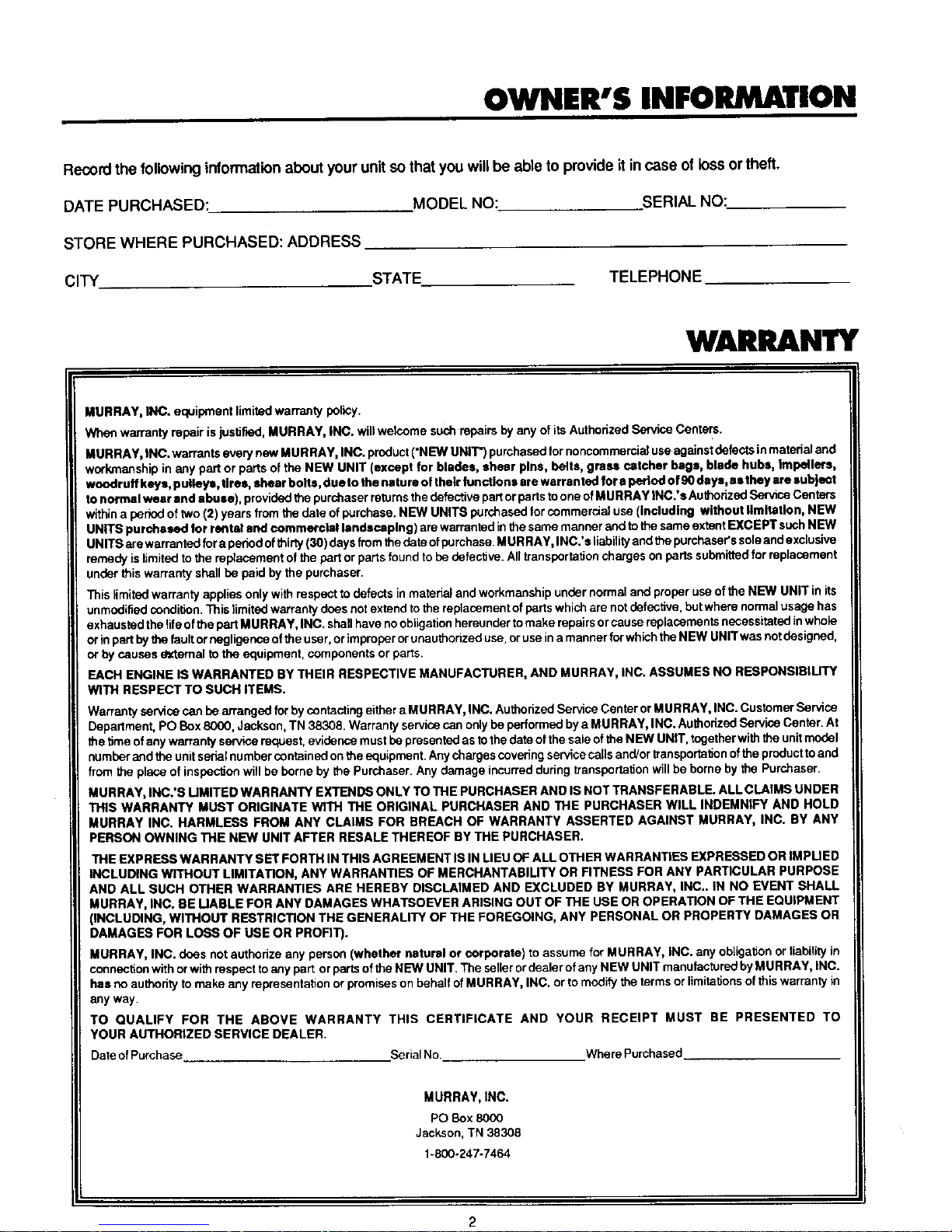
OWNER'S INFORMATION
Record the following information about your unit so that you will be able to provide it in case of loss or theft.
DATE PURCHASED:
STORE WHERE PURCHASED: ADDRESS
CITY
MODEL NO: SERIAL NO:
STATE
TELEPHONE
WAIlU NTY
dURRAY, INC. equipment limited warranty policy.
Whan warranty repair is justified, MURRAY, INC. will welcome such repairs by any of its Authorized Service Centers.
MUR RAY, INC. warrants every new MURRAY, INC. product ("NEW UNIT") purchased for noncommercia] use against defectsin mateda] and
workmanship in any part or parts ofthe NEW UNIT (except for blades, shear pins, belts, grass catcher bags, blade hubs, impellers,
woodruff keys, pulleys, tires, shear bolts, due to the nature of thetr lunctlo ns are warranted for a period of 90 days, as they are subject
to normal wear and abuse), provided the purchaser returnsthe defective partor ports toone of MURRAY INC.'s Authorized Service Centers
within a periodof two (2) years from the date of purchase. NEW UNITS purchased for commercial use (including without limitation, NEW
UNITS purchased for rental sod commercial landscaping) are warranted inthe same manner and to the same extent EXCEPT such NEW
UNITS are warranted for a period of thirty (30) days from the date ofpurchase MURRAY, INC.'s liability and the purchaser's soleand exclusive
remedy is limited to the repfecament of thepart orparts found to be dafectJve. All transportation charges on parts submitted for replacement
under this warranty shall be paid by the purchaser.
This limited warranty applies only with respect to defects in material and workmanship under normal and proper use of the NEW UNIT in its
unmodified condition. This _imited warranty does not extend to the replacement ofparts which are not defective, but where normal usage has
exhausted the life of the part M URRAY, INC. shall have no obiigatlen hereunder to make repairs orcause replacements necessitated in whole
or inpart by _e fault or negligence of the uset, orimproper orunauthorized use, or use in amanner forwhich the NEW UNIT was not designed,
or by causes external to the equipment, components or parts.
EACH ENGINE IS WARRANTED BY THEIR RESPECTIVE MANUFACTURER, AND MURRAY, INC. ASSUMES NO RESPONSIBIUTY
WITH RESPECT TO SUCH ITEMS.
Warranty service can be arranged for by contacting either a MURRAY, INC. Authorized Service Center or MURRAY, INC. Customer Service
Department, PO Box 8000, Jackson, TN 38.308. Warranty service can only be performed by a MURRAY, INC. Authorized Service Center. At
the time of any WarTantyservice request, evidence must be presented as tothe date of the sale of the NEW UNIT, together with the unitmodel
number and the unit sedal nutuber contained onthe equipment. Any charges coved ngservice calls and/or tran sporfationofthe product to and
from the place of inspectJan will be borne by the Purchaser. Any damage incurred during transportation will be borne by the Purchaser.
MURRAY, INC.'S UMITED WARRANTY EXTENDS ONLY TO THE PURCHASER AND IS NOT TRANSFERABLE. ALL CLAIMS UNDER
THIS WARRANTY MUST ORIGINATE WITH THE ORIGINAL PURCHASER AND THE PURCHASER WILL INDEMNIFY AND HOLD
MURRAY INC. HARMLESS FROM ANY CLAIMS FOR BREACH OF WARRANTY ASSERTED AGAINST MURRAY, INC. BY ANY
PERSON OWNING THE NEW UNIT AFTER RESALE THEREOF BY THE PURCHASER.
THE EXPRESS WARRANTY SET FORTH IN THIS AGREEMENT IS IN LIEU OF ALL OTHER WARRANTIES EXPRESSED OR IMPUED
INCLUDING WITHOUT LIMITATION, ANY WARRANTIES OF MERCHANTABILITY OR FITNESS FOR ANY PARTICULAR PURPOSE
AND ALL SUCH OTHER WARRANTIES ARE HEREBY DISCLAIMED AND EXCLUDED BY MURRAY, INC.. IN NO EVENT SHALL
MURRAY, INC. BE UABLE FOR ANY DAMAGES WHATSOEVER ARISING OUT OF THE USE OR OPERATION OF THE EQUIPMENT
(INCLUDING, WITHOUT RESTRICTION THE GENERALITY OF THE FOREGOING, ANY PERSONAL OR PROPERTY DAMAGES OR
DAMAGES FOR LOSS OF USE OR PROFIT).
MURRAY, INC. does not authorize any person (whether natural or corporate) to assume for MURRAY, iNC. any obligation or liability in
connection with or with respect to any part orparts of the NEW UNIT. The seller ordealer of any NEW UNIT manufactured by MURRAY, INC.
has no authority to make any representation or promises on behalf of MURRAY, INC. or to modify the terms or limitationsofthis warranty in
any way.
TO QUALIFY FOR THE ABOVE WARRANTY THIS CERTIFICATE AND YOUR RECEIPT MUST BE PRESENTED TO
YOUR AUTHORIZED SERVICE DEALER.
Date of Purchase Serial No. Where Purchased
MURRAY, INC.
PO Box 8000
Jackson, TN 38308
1-800-247-7464
Page 3
TABLE OF €ONTENTS
WARRAN'[Y ........................................................................ 2
INTERNATIONAL SYMBOLS ............................................. 4
OWNER'S INFORMATION ................................................. 5
RESPONSIBILITY OF THE OWNER .................................. 5
SAFETY RULES .............................................................. 5-6
SAFE MOWING GUIDE ................................................... 7-9
STEPS TO FOLLOW ........................................................ 10
ASSEMBLY..................................................................11-14
OPERATION................................................................15-19
MAINTENANCE...........................................................20-26
ADJUSTMENTS...........................................................27-30
TROUBLESHOOTINGGUIDE.....................................31-32
STORAGE.........................................................................33
SLOPEGUIDE ..................................................................34
Fill in and mail the registration card packed with the unit. For service other than covered in this manual, contact an authorized
service dealer. A nationwide parts and service organization has been established to provide locally available parts and service. A
list of authorized parts distributors has been included in the Repair Parts manual.
IS NOTE 1
ome tractor models may require different instructions for assembly and/or repair than shown in this manual. The
apalr Parts manual (supplied with tractor) will contain these instructions if required on your model.
This lawn tractor Is equipped with an Internal combustion engine end should not be used on or near any
unimproved forest-covered, brush-covered, or grass-covered land unless the engine's exhaust system Is
equipped with s spark errester meeting applicable local or state laws (If any). If a spark arreeter Is used, It
should be maintained In effective working order by the operator.
In the State of California the above Is required by law (Secticn 4442 of the California Public Resources Code).
Other states may have similar laws. Federal laws apply on federal lands. A spark arrsster for the muffler Is
available through an Authorized Service Center
References throughout this manual concerning the right or left side are determined as you face forward while
seated in operator's seat.
Photographsand illustrationsin this manual may notshow yourmodelbut are for reference.Theyare based on the latest
information.
California Proposition65 WARNING!
The engine exhaust from this product contains chemicals known to the State of
California to cause cancer, birth defects or other reproductive harm.
Page 4
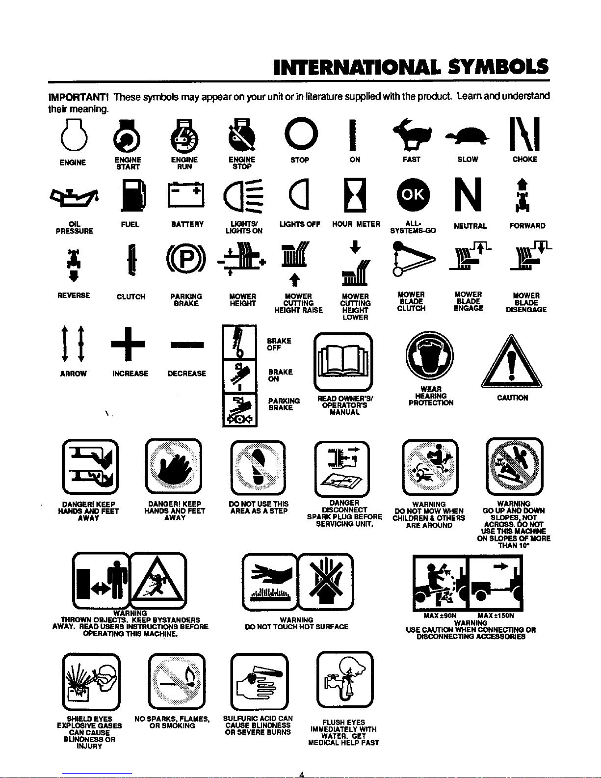
INTERNATIONAL SYMBOLS
IMPORTANT! These symbolsmay appear on your unitor In literature suppliedwith the product. Learn and understand
their meaning.
© O I I\1
ENGINE ENGINE ENGINE ENGINE STOP ON FAST SLOW CHOKE
START RUN STOP
O4L FUEL BAI"rERY LIGHTS/ LIGHTSOFF HOUR METER ALL- NEUTRAL FORWARD
pRESSURE LIGHTSON SYSTEMS-GO
REVERSE CLUTCH PARKING MOWER MOWER MOWER MOWER MOWER MOWER
BRAKE HEIGHT CUTTING CUTi'ING BLADE BLADE BLADE
HEIGHT RAISE HEIGHT CLUTCH ENGAGE DISENGAGE
LOWER
l
ARROW INCREASE DECREASE
l
,D(;])O
l
OFF
_4 AKE
• )
PARKING READOWNER'S/ HEARING CAUTION
BRAKE OPEEATOR'S PROTECTION
MANUAL
DANGERI KEEP DANGER! KEEP
HANO6 AND FEET HANDS AND FEET
AWAY AWAY
WARNING
THROWN OBJECTS. KEEP BYRTANDERS
AWAY. READ USERS INSTRUCTIONS BEFORE
OPERATING THIS MACHINE.
DO NOT USE THIS
AREAAS A STEP
DANGER WARNING WARNING
DISCONNECT DO NOT MOWWHEN GO UPAND DOWN
SPARK PLUG BEFORE CHILDREN & OTHERS SLOPES NOT
SERVICING UNIT. AREAROUND ACROSS. _ NOT
USE THB MACHtNE
ON SLOPES OF MORE
THAN 10_
WARNING
DO NOT TOUCH HOT SURFACE
MAX ig0N MAX±150N
WARNING
USE CAUTION WHEN CONNECTING OR
DISCONNECTING ACCESSORIES
SHIELD EYES
EXPLO_NE GASES
CAN CAUSE
BLINONESS OR
INJURY
NOSPARKS, FLAMES,
OR SMOKING
SULFURIC ACID CAN
CADSE BLINDNESS FLUSH EYES
OR SEVERE BURNS IMMEDIATELY WITH
WATER. GET
MEDICAL HELP FAST
4
Page 5
OWNER'S INFORMATION
This Ownar's/Operatol's Manual isfor several differentmodels. The instructionsare writtenfora personwithsome mechanical abiitly.
Lke mostseMca books, not all the stepsare described. Stops on howto loosen or tighten fasteners are steps anyone can follow with
some mechanical ability. Read and followthese instructionsbefore you use the unit.
Know your product: Ifyou understand the unit and howthe unitoperates, you willgetthe best performance. Asyou reed this manual,
compare the illustrationstothe unit. Learn the iocat ion and thefunctionofthe controls.To help prevent an accident, followthe operating
instructionsand the safety rules. Keep this manual for future reference.
IMPORTANT: Many unitsam notassembled and am sold in cartons, it isthe responsibilityofthe owner to make sure the assembly
instructionsinthis manual are exactly followed. Other unitsare purchased in an assembled condition. On assembled units,it isthe
responsibility of the owner to make sure the unit is correctly assembled. The owner must carefully check the unit according to the
instructionsin this manual before it isfirst used.
RESPONSIBILITY OF THE OWNER
The responsibilityof the owner Is to followthe instructions
below.
1. Carefullyreadandfollowtherubesforsafeoperation.
2. Followallthe assemblyinstructions.
3. Inspectthe unit.
4, Makesuratheoparatoroftheunitknowshowtocorrectlyuse
allstandardandaccessoryequipment.
5. Operatetheunitonlywithguards,shields,andothersafety
items inplaceandworkingcorrectly.
6. Correctlyadjustthe unit,
•7. Servicethe unitonlywithauthorizedor approvedreplace-
meritparts.
8. Completeallmaintenanceontheunit.
EnvironmentalAwareness
• Do notfilltheengine'sfueltankcompletelyfull.
• Drainfuelforoff-seasonstorage.
• Useonlyunleadedgasoline.
• Servicethe aircleanerregularly.
• Changeoilregularly.Use30Woil insummer.
• Tune-uptheengineregularly.
• Keepequipmentinefficientoper_ingcondition,
• Disposeof usedengineoilpmpedy.
SAFETY RULES
Safe Operation Practices for Riding Vehicles
As Recommended by American National Standards Institute
WARNING: This cuffing machine Is capable of amputating hands and feet and throwing objects. Failure to observe
the following safety Inatructlona could result In serious Injury or death to the operator or bystanders.
GENERAL OPERATION:
1. Reed, understand and follow aU instructions in the Owner's/Operator's Manual, on the machine, the engine and with any
attachments before starting.
2. Only allow responsible adultsfamiliar withthe instructionsto operate the machine.
3. Clear the area ofobjects such as rocks, toys,wire, etc. which could be picked upand thrown by the blade.
4. Be sure the area isclear of other psople bafore mowing. Stop ths machine if anyone enters ths area.
5. Never carry passengers.
6. Disengagepowertothemoweroranyattachmentsbaforebackingup. Donotmowinreverseuniessabsclutelynecessary. Allays
lookdown and behind before and while backing.
7. Beawaraofthedirectionthemowerdischargas. Donotpointdischargefromthemoweratanyoneoratplaceswherepeopiemay
be. Do not operate the mower without either the entire grass bagger or the mower guard in place.
8. Slow down beforeturning.
9. Nevarieaveamschineunatlendedwiththeenginerunning. Alwaysdisengagetheblade(s),settheparkingbrake, stoptheengine
and remove the key before dismounting.
10. Disengagepowertoattachment(s)whentranspertingornotinuse. Disangaga the blade(s) when not mowing.
11. Stop the engine before removing the grass bagger or uncloggingthe chute.
12. Mow only in daylight or good artificiallight.
13. Do not operate the machine while underthe influence of alcohol or drugs or when very tired.
14. Do notoperate thismachine it youara taking drugsorother medication whichcen cause drowsiness oraffect your abilityto operate
this machine.
15. Do not use this machine it you are mentally or physically unable to operate this machine safely.
16. Watch for traffic when operating near or crossing roadways.
17. Use extracaution when loading or unloading the machine when using a trailer or truckfor transporting.
18. Disengage all attachment clutches and shifl into Neutral before attemptingto start the engine (on gear drive models).
19. Disangageallattachmantclutchesbaforeattemptingtostarttheengine(onhydromodela).
20. Allaysw_arsafetyg_asses_r_neyeshie_dwh_ny_u_perateth_unitt_pr_tacty_ureyesfmmf_reign_bjectsthatcanbathr_wn
from the unit. Always wear eye pmtectldn when you make an adjustment or repair to the machine.
21. Use care when pullingloads or using heavy equipment.
a. Use only approved drawbar hitch points.
b. Limit loads to those you can safely control.
c. DOnot turn sharply. Use care when backing.
d. Use counterweights when suggested inthe Owner's/Operator's Manual.
5
Page 6
SLOPE OPERATION:
Slopesand roughterrainare major factors relatedto lossofcontrolandtip overaccidentswhich canresult Insevereinjury
or death. ALL slopesrequireextra caution, if you cannot backupthe elope or Hyou feel uneasy onthe slope,do not mow
It. See the "Slope Guide"Inthe back ofthis book to check for safe operaticn.
DO
1. Mow up and down slopes, not across.
2. Remove obstacles such as rocks, limbs, etc...
3. Watch for holes, ruts or bumps. Uneven terrain could overturn the machine. "Tall grass can hide obstacles."
4. Use slow speed. Choose a low enough gear sothat you will not have to stop or shiftwhile onthe slope (on gear drive models).
5. Use slow speed on slopes. Do notmake sudden speed changes (on hydro models).
6. Followthe manufacturer's recommendations for wheel weights or counterweights to improve stability.
7. Use extra care with grass baggers or other attachments, they can change the stabilityof the machine.
8. Ksap afl movement on the slopes slow end gradual. Do not make suddon changes in speed or direction.
9. Avoidstarting or stopping on a slope. H tires lose traction, disengage the blades and proceed slowlystraight down the slope.
DO NOT
1. DO Ilot tum en slopes unless absolutely necessary, then only turn slowlyand gradually downhill, ifpossible.
2. Donotmownsardmp-offs, ditchesorembankments. Awheelovertheedgeoranedgecavingincouldcauseasuddenoverturn
and an injury or death.
3. Do nct mow on wet grass. Reduced trastlon could cause sliding.
4. Do nct tryto stabilize the machine by puttingyour foot on the ground.
5. Do not use a grass catcher or other rear mounted accessories on steep slopes (greater than 10 degrees).
CHILDREN:
Tragic accidents can occur If the operator is not alart to the presence of children. Children are often attracted to the machine
and the mowing actlvify. NEVER assume that children witl remain where you last saw them.
1. Ksap children out of the mowing area and inthe watchfulcare of an edult other than the operator.
2. Be alert and turn the engine off it children enter the area.
3. Before and when backing, look behind and down for small children.
4. Never carry children or any passengers. They may fall off and be seriously injures or interfere with the safe operation of the
machine.
5. Never allow children to operate the machine. Instructchildren in the dangers of the machine.
6. Use extr_ care when approaching blind corners, shrubs, trees or other objects that may obscurevision.
SERVICE:
1. Use extra care when handling gasoline and other fuels. Fuels are flammable and the vapors are explosive.
e. Use only an approved container.
b. Never remove the gas cap or add fuel withthe engine running. Allowthe engine to coolfor several minutes before refueling.
Do not smoke.
c. Never refuel the machine indoors.
d. Never store the machine withfuel inthe tank or fuel container inside where there is an open flame, such as a water heater.
2. Never start or runthe engine inside a closed area.
3. Kaspaflnutsandboits, especiaily the blade attachment nuts tight. Frequentlycheckthebtade(a)forwearordamagesuchas
cracks and nicks. A blade that is bent or damaged must be immediately replaced with an original equipment blade(a) from an
authorized service dealer. For safety, replace the blade(s) every two years. Keep the equipment in good condition.
4. Nevertamperwiththesafetydevioes. Check their proper operatlonregutarly.
5. Toreducefirehazardskespthemachinefreeofgrass, leavasorotherdebrisbuild-up. Cleanupoilorfuelspills. Allowthemashine
to cool before storing.
6. Stop and inspect the equipment ifyour strike an object. Repair, if necessary, before restarting.
7. Never make adjustments or repairs with the engine running. The carburetor can be adjusted with the engine running. Do not
change the engine governor settings or over-speed the engine.
8. Grass begger components are subject to wear, damage and deterioration,which could expose moving partsor allow objects to
bathrown. Forstorage, always make surethe grass bag isempty. Frequently check components and replace withmanufacturer's
recommended parts when necessary.
9. Mower blade(s) are sharp and can cut. Wrap the blade(s) orwear gloves and use extracaution when servicingthem orthe mower
deck area.
10. Check the brake operation frequently. Adjust and service as required.
11. Wait for all movement to stop before servicing any part of the unit.
Look for thla symbol to Indicate important safety precautions. This symbol indicates: "Attention! Become Alert"
Your Safety Is At Rlak."
Page 7
SAFE MOWING GUIDE
Each person that operates power equip-
ment must learn to use correct and safe
mowing procedures. To help you learn,
carefully read the followlng pages. Most
of the time the operator was not correctly
shown or did cot read the instructionson
theunitorinthe Ownar'siOperator's Manual
before using the unit. Also, some opera-
tots do not have enough experience. The
result is unsafe use, endangering the op-
erator, bystandersand the equipmant. An-
other result can be a poor appearance of
the area mowed.
Readthlsbook. Readthe instructionson
the unit.Operatethemoweraccordingto
theSafe MowingGuide. Followalls_ety
ruios,cautionsorwarningsinthisbookand
onthe unit. Makesureanyonethatuses
the unit readsthe instructionsand istold
howtosafelyoperatethemower.
The mower will give you good service and
durability, itoperatad innormalconditions.
Ifthe mower is not correctly serviced or is
used where the terrain is rough or unsuit-
able, product performance and safety will
be decreasad.
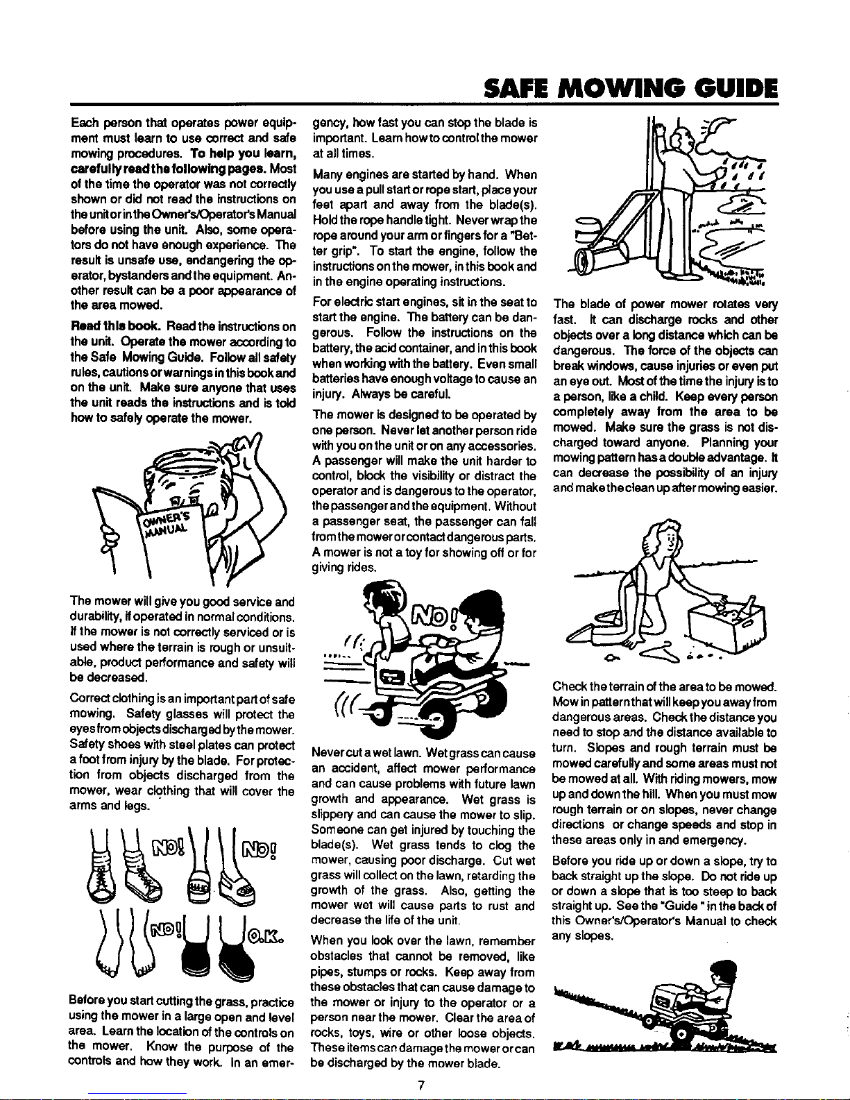
Correct clothingis an importantpartofsafe
mowing. Safety glasses will protect the
eyes from objectsdisohargedbythe mower.
Safety shoes with steel plates can protect
a footfrom injury by the blade. For protec-
tion from objects discharged from the
mower, wear ck?.thingthat will cover the
arms and legs.
Before you start cuttingthe grass, practice
usingthe mower ina large open and level
area. Learn the location of the controls on
the mower. Know the purpose of the
controls and how they work. In an emer-
gancy, how fast youcan stop the blade is
important. Learn howtocontrol the mower
at all times.
Many engines are startedby hand. When
youuse a pullstartorropestart, place your
feet apart and away from the blade(s).
Holdthe rope handle tight. Never wrap the
rope around your arm orfingersfor a"Bet-
ter grip". To startthe engine, follow the
instructionsonthe mower, inthis book and
inthe engine operating instructions.
For electric start engines, sit inthe seat to
startthe engine. The battary can be dan-
gerous. Follow the instructions on the
battery,the acid container, and inthisbook
when working withthe battery. Even small
batteries haveenough voltagetocause an
injury. Always be careful.
The mower is designed to be operated by
one person. Never let another person ride
withyouon the unitor on any accessories.
A passenger will make the unit harder to
control, block the visibilityor distract the
operatorand isdangerousto the operator,
the passengerand the equipment+Without
a passenger seat, the passenger can fall
fromthe mower orcootactdangerous parts.
A mower is not a toyfor showing off orfor
givingrides.
Never cutawet lawn. Wet grasscan cause
an accident, affect mower performance
and can cause problems with future lawn
growth and appearance. Wet grass is
slipperyand can cause the mower to slip.
Someone can get injured by touching the
blade(s). Wet grass tends to clog the
mower, causing poor discharge. Cut wet
grass willcollectonthe lawn, retardingthe
growth of the grass. Also, getting the
mower wet will cause parts to rust and
decrease the life of the unit.
When you look over the lawn, remember
obstacles that cannot be removad, like
pipes, stumps or racks. Keep away from
these obstacles thatcan cause damage to
the mower or injury to the operator or a
person near the mower. Clear the areaof
rocks, toys, wire or other loose objects.
These itemscan damage themower or can
be discharged by the mower blade.
The blade of power mower rotates very
fast. It can discharge rocks and other
objects over a long distance which can be
dangerous. The force of the objects can
break windows, cause injuries oreven put
an eye oat. Most of the time the injuryis to
a person, like a child. Keep avery person
completely away from the area to be
mowed. Make sure the grass is cot dis-
charged toward anyone. Planning your
mowing patternhas a double advantage. It
can decrease the possibility of an injury
and makethe clean up aftermowing easier.
Check the terrain ofthe area tobe mowed.
Mow inpatternthat willkeep you away from
dangerous areas. Check the distanceyou
need to stop and the distance available to
turn. Slopes and rough terrain must be
mowed carefully and some areas must cot
be mowed at all. With ridingmowers, mow
upand down the hill. When you mustmow
roughterrain or on slopes, never change
directions or change speeds and stop in
these areas only in and emergency.
Before you ride up or down a slope, try to
back straightupthe slope. Do not ride up
or down a slope that istoo steep to beck
straight up. See the "Guide "in the back of
this Owner's/Operator's Manual to check
any slopes.
Page 8

SAFE MOWING GUIDE
Before you start cutting, make sure the
mowerwas completely assembled accord-
ingto the Owner's/Operator's Manual. If
the mower was completely assembled at
the store, you must stillcheck the mower
according to the assembly instructions.
Make sure the mower is correctly as-
sembled and that all fasteners are tight.
Make sure the engine has the correct
amount of oil. Check these items often
during the lifeof the mower.
Your mower hasagasoline engine. Gaso-
line is a dangerous fuel. Keep gasoline
only in an approved safety gasoline con-
tainer. Do not keep large amounts of
gasoline. When you add gasoline to the
fueltank, do notsmoke. Storethe gasoline
container and the mower in an area that
hasgoodventilation. Also, keep the gaso-
lineaway from any flameslikethe pilot light
of afurnace or anyother soume of ignition.
Ifthe mower isto be stored for more than a
few weeks, remove the gasoline from the
fuel tank. When inside an enclosure, do
not add gasoline to the fuel tank. Before
you add gasoline move the mower outside
and add gasoline carefully. Before your
start theengine,remove anygasolinefrom
the outside of the fuel tank or from the
mower. Warm gasolinewillexpand. Leave
somespace int_tefuel tankforthe gasoline
to expand. Also, the fuel cap has a vent
holefor fuelvapors. Always usethe correct
fuel cap. Failure to follow safety rules
aboutgasoline wigcause fires and explo-
sions, injury to you and damage to the
equipment and other property.
If you add gasoline to an engine that is
runningor hot, the resultcan be an explo-
sion. Before you add gasoline, stop the
engine and let the engine cootfor several
seconds. Remove dry grass and other
debris from the mower. Keep the mower
cleanto improvetbe performance, helpthe
engine and transmission run cooler,ex-
tendthe likeof movingparts, and decrease
the danger of a fire.
Fires and explosions are notthe onlydan-
gers when working around a mower. The
engine, transmission, and the muffler will
get hotinseveral minutes when the engine
isrunning. Do not touch these parts ofthe
mower. Stop the engine. Let the engine
and transmission cool before servicingthe
mower Remember, exhaust fumes aredan-
gerous. Never operate the engine insidea
building.
When you get anew mower, itcan be anew
experience for thefamily. Tell each person
how a mower can bedangerous. Remem-
ber, a mower isnot a toy. A mower is not
to be used by children or anyone not old
enough, strong enough or that does not
have experience.
Ifthe mower isnotcorrectlyassembled, not
operated correctly, or not regularly ser-
viced, the mower can be dangerous. The
most importantruletofollow is always use
goodjudgement and common sense. Mow
safely and carefully.
Your mower will easily cut thick grass.
Fingers, feet and other parts can also be
cut by the blade. Injuries occur when the
operator does not think and reaches into
the chute opening. Always operate the
mower as if the blade is rotating. Do not
service or make an adjustment, except to
thecarburetor,whilethe engine is running.
Use only accessories that are factory ap-
proved for your mower. The wrong acces-
sorycan decrease the safety of the mower
and can even damage the unit. Read and
follow the instructions included with the
accessory and the mower.
Use only original equipment or replace-
ment parts that are factory approved for
service, if you need service, select and
Authorized Service Center for your mower.
If you do the work on the unit, follow the
instructions in the Owner's/Operator's
Manual.
When you mow, remember that children
are attracted to the mower. Always use
caution when mowing around obstacles
like trees or shrubs or when movingback-
ward. Only mow in a forward direction if
passible. Your visibilityisdecreasad when
you mow backward. Also,the blades are
made to cut while the unit is moving for-
ward. If you mow backward, the cutting
performance decreases.
Before you leave the mower, stop the en-
gine. Remove the key. Disengage and
lower any attachment. Set the parking
brake. Never mount or dismountfrom the
seat while the engine is running. An acci-
dent can occurif you touchthe brake, shift
lever,throttle,clutch,ormowerclutch lever
while the engine is running. Mount and
dismount from the seat on the side oppo-
site the discharge chute.
Make sure you are in good condition when
you mow. When you mow for several
hours your reflexes willdecrease and your
mind willnotbe as alert. Take ashortbreak
or an accident can occur. Ifthe tempera-
ture ishot,use cautiontoprevent dehydra-
tion. If you are tired, angry or not com-
pletely alert, do not operate the mower. If
you use alcohol, medication or drugs, do
not use the mower or any type of power
equipment.
Engine speed is a key to safe mowing and
to a good looking lawn. The maximum
speed of the engine was set atthe factory.
Do not change the setting of the engine
governor.
Select the maximum engine and ground
speed that is rightfor the terrain and the
height of the grass. The blade cuts best
when the engine is operating at maximum
Page 9
SAFE MOWING GUIDE
speed. Also, thegrasscatcher willfunction
better when the engine is operating at
maximum speed. On slopes,decrease the
ground speed and use care making sure
mower feels safe to operate.
ff the weather conditions are bad, do not
mow. ff weather conditions become bed,
stopcuttingand finish later. Itisdangerous
tocutgrass inthe rain. Always find protec-
tion in an electrical storm. If the weather
conditionsare extra dry, protectyour eyes
with safety glasses from the dust and from
the objectsdischargedbythemower. Also,
a dust or a pollen mask can help.
Your mower is equipped with a number of
safety devices which are important to the
safety ofthe operator and bystanders and
must never be changed or removed from
the mower. If a safety device is lost,
damaged or no longer functions, repair or
replace the device beforeyou operate the
mower.
it isbest to mow duringthe day. If you must
mow at night, make sure there is enough
lightfor safe operation.
Your mower will require regular mainte-
nance and service. The maintenance
schedule depends on the hours of use.
Also, mowing conditions can change the
schedule. Check the Owner's/Operator's
Manualformore information. Correct main-
tenance will helpthe mower function safely.
Do not service the mower
(except for the carburetor f/
adjustment) while the en-
gine is running. Beforeil_i
you servicethe unit,even _:i _
with the eng ne stopped, i_,-
alwaysdisconnectthewire
fromthe spark plugto pre-
ventthe engine from start-
ing.
If you hit a large object during operation,
stopthe engine. Remove the wirefromthe
sparkplug. Carefully inspectthe mowerfor
damage. Before youstartthe engineagain,
make the necessary repairs. If you feel
new or excessive vibration, immediately
stopthe engine andcheck for the problem.
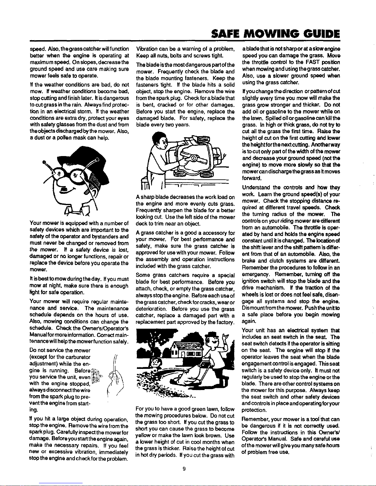
Vibrationcanbe a warningofa problem,
Keepallnuts,belts and screwstight.
The blade isthe most dangerous pert ofthe
mower. Frequently check the blade and
the blade mounting fasteners. Keep the
fasteners tight. If the blade hits a solid
object, stopthe engine. Remove the wire
from thespark plug. Check forablade that
is bent, cracked or for other damages.
Before you start the engine, replace the
damaged blade. For safety, replace the
blade every two years.
A sharp blade decreases the work load on
the engine and more evenly cuts grass.
Frequently sharpen the blade for a better
lookingcut. Use the left sideof the mower
desk totrim near an object.
A grass catcher is a good a accessory for
your mower. For best performance and
safety, make sure the grass catcher is
approved for usewith your mower. Follow
the assembly and operation instructions
included with the grass catcher.
Some grass catchers require a special
blade for best performance. Before you
attach, check, or empty the grass catcher,
alwaysstopthe angina. Before each useof
thegrasscatcher,checkfor cracks,wearor
deterioration. Before you use the grass
catcher, replace a damaged part with a
replacement partapproved by the factory.
For you to have a good green lawn, follow
the mowing procedures below. Do notcut
the grass too short. Ifyou cut the grass to
short you can cause the grass to become
yellow or make the lawn look brown. Use
a lower height of cut in cool monthswhen
the grass isthicker. Raise the heightofcut
inhot dry periods. Ifyoucutthe grass with
9
abladethat is notsharpor at a slow engine
speed you can damage the grass. Move
the throttle control to the FAST position
when mowing and usingthe grass catcher.
Also, use a slower ground speed when
using the grass catcher.
Ifyouchange the direction orpatternofcut
slightlyevery time you mow will make the
grass grow stronger and thicker. Do not
add oilor gasoline to the mower while on
the lawn. Spilled oilor gasolinecan killthe
grass. In high orthick grass, do nottry to
cut all the grass the first time. Raise the
heightof cut on the first cuttingand lower
the heightfor the next cutting.Anotherway
isto cut only partofthe width ofthe mower
and decrease your ground speed (not the
engine) to move more slowly so that the
mower can dischargethegrassas itmoves
forward.
Understand the controls and how they
work. Learn the ground speed(s) of your
mower. Check the stopping distance re-
quired at different travel speeds. Check
the turning radius of the mower. The
controlson your ridingmower are different
from an automobile. The throttle is oper-
ated by hand and holds the engine speed
constant untilitischanged. The lo_tion of
the shiftleverand the shiftpattern isdiffer-
ent from that of an automobile. Also, the
brake and clutch systems are different.
Remember the procedures tofollow in an
emergency. Remember, turning off the
ignition switch will stop the blade and the
drive mechanism. If the traction of the
wheels is lostor does not feel safe, disen-
gage all systems and stop the engine.
Dismountfromthe mower. Pushthe unitto
a safe place before you begin mowing
again.
Your unit has an electrical system that
includes an seat switch in the seat. The
seat switchdetects if the operator is sitting
on the seat. The engine will stop If the
operator leaves the seat when the blade
engagement controlisengaged. This seat
switch isa safety device only. It must not
regularlybe used to stopthe engine orthe
blade. There are other control systemson
the mower for thispurpose. Always keep
the seat switch and other safety devices
andcontrols inplace and operating foryour
protection.
Remember, your mower is a toofthat can
be dangerous if it is not correctly used.
Follow the instructions in this Owner's/
Operator's Manual. Safe and careful use
ofthe mower willgive youmany safe hours
of problem free use.
Page 10
STEPS TO FOLLOW
BEFORE MOWING
Be sure to dress correctly, Wear hard shoes, not sandals or tennis shoes.
Examine the blade. A blade that is bent, cracked or damaged must be replaced with a factory replacement blade,
Fillthe fuel tank outside. Clean off spitledfuel.
Reed and follow the Owner's/Operator's Manual, the instructions with the engine, and the instructionswith any attachments.
Owner's/Operator's Manual instructionsare for your safety and the safety of others.
Exhaust fumes are dangerous. Start the engine outside.
Make sure all safety devices are inplace and working correctly,
Operation of the mower is only for a person that has experience.
Wet grass can be dangerous. Let the grass dry.
Instruct children and others to keep away from the work area.
Never cut the grass without good light.
Pick up loose objects. Remove them from the mowing area,
WHILE MOWING
Watch for fixed objects and avoid them. They can damage the mower or cause injury.
A hot angina, muffler, and transmission willcause a burn. Do not touch.
Inclines and slopes must be carefulry mowed. Sea the *Guide" in the back ofthis book tocheck a slope.
Lack of daylight or good artificial lightis cause to stop mowing.
Examine the mower, the blade, and other parts for damage after hittinga foreign object or ifthe unitvibrates excessively.
Do cot make adjustments or repairswithout stopping the engine (except for carburetor). Disconnect the spark plug wire.
On or near roads, watch out fortraffic, Direct discharge away from roads.
\
When mow ng, avoid areas where traction s unsure. Look back before changingdirection of travel.
In heavy grass, raise the cutting height. Cut slower. Stop the engine to remove clogged grass from the mower.
Never remove any safety related parts.
Do not pour gasoline intoa engine that is hotor running.
AFTER MOWING
Always let the mower cool before storing in an enclosed area.
Foreign matedal on the mower is daagemus. Clean off grass, leaves, grease, and oil before storing.
Tighten all loose nuts, belts, and screws before you use the unit.
Empty and clean any grass catcher or other accessory.
Remove the key or disconnect the spark plug wire to prevent unauthorized use.
Make sure the mower is not kept near a source of ignition. Gas fumes can cause an explosion.
Only original parts or factory approved substitutescan be used to servicethe mower.
When storing the mower for an extended period, remove the fuel from the fuel tank,
Instruct children to leave the mower alone, if is cot a toy.
Never keep gasoline near a source of ignition. Always use an approved container. Keep gasoline away from children,
Lubricate according to the Owner's/operator's Manual. See "Lubrication'.
IMPORTANT- READ THE OWNER'S/OPERATOR'S MANUAL. KEEP THIS BOOK FOR FUTURE USE AND REFERENCE.
A_ WARNING: Look for this symbol to point out important safety precautions. It means: "Attention! Become Alert!
Your Safety Is involved."
10
Page 11
ASSEMBLY
Your lawn tractor has a right side and left side as you face
forward while seated in operator's seat.
TO ACTIVATE BATTERY
IMPORTANT: : Before you attach the battery cables to the
battery,check the batterydate code. The batterydatecodetells
if the battery must be charged.
1. Check the battery date code on top of the battery.
2. If the battery is put into service before the battery date, the
batterycables can be attached withoutcharging the battery.
See Battery Instaifatlon paragraph in Maintenance sec-
tionof this manual.
3. If the battery is put into service after the battery date, the
battery must be charged. To charge proceed:
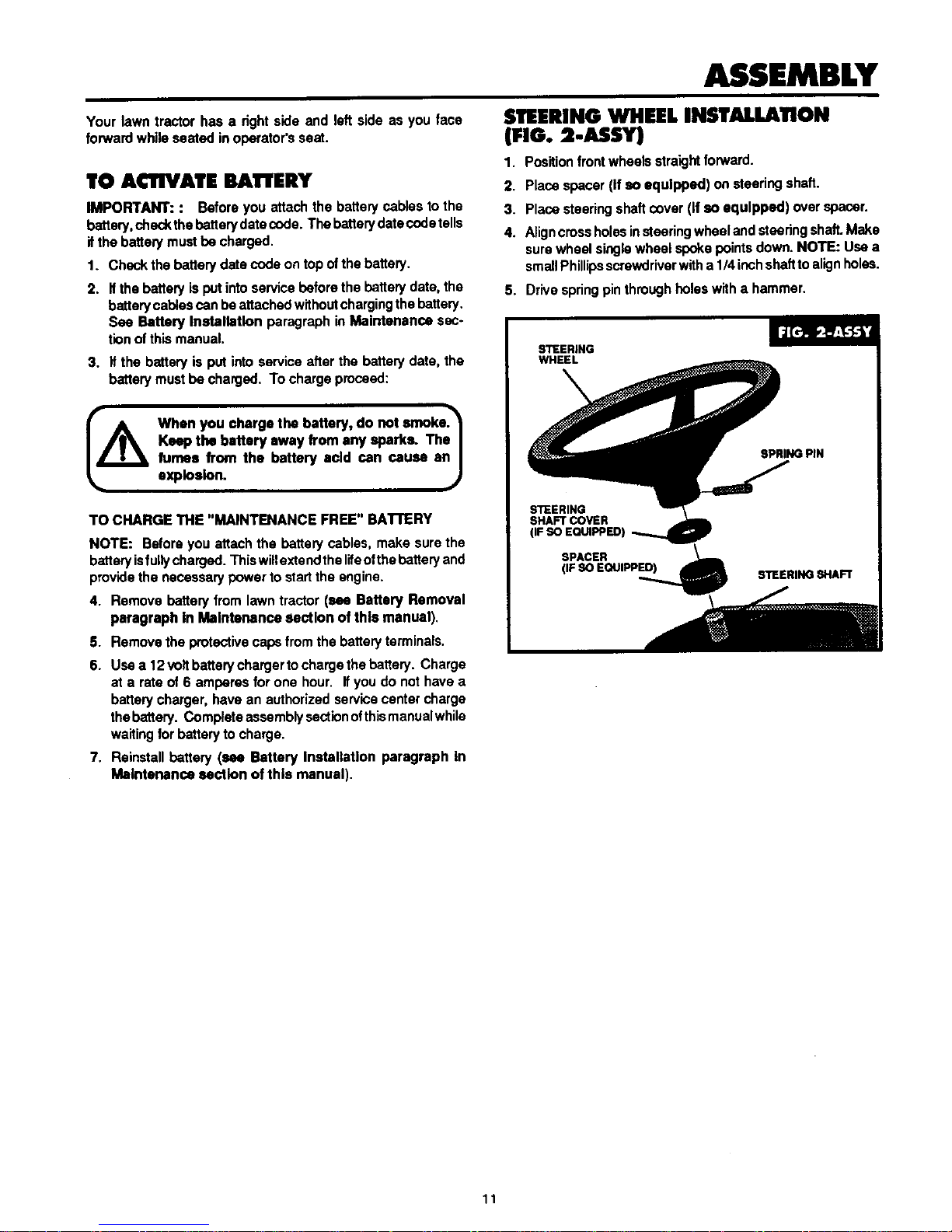
STEERING WHEEL INSTALLATION
(FIG.=-ASSY)
1. Position front wheels straightforward.
2. Placa spacer (If so equipped) on steering shaft.
3. Place steering shaft cover (If so equipped) over spacer.
4. Aligncross holesin stesring wheel and steeringshaft.Make
sure wheel single wheel spoke points down. NOTE: Use a
smallPhillipsscrewdriver witha 114inchshaftto alignholes.
5. Drivespring pin through holes with a hammer.
IA When you charge the battery, do not moks.'_
Keepthe battery away from anysparks. Ths_
fumes from the battery acid can cause anJ
explosion. ._
TO CHARGE THE "MAINTENANCE FREE"BATEERY
NOTE: Before you attach the battery cables, make sure the
batteryisful;y charged. This willextsndthe lifeofthe battery and
providethe necessary power to start the engine.
4. Removebatteryfromlawntractor(see Battery Removal
paragraph In Maintenancesection ofthis manual).
S. Removstheprotectivecapsfromthebattaryterminais.
6. Use a 12 volt battery charger tocharge the battery. Charge
at a rate of 6 amperes for one hour. If you do not have a
battery charger, have an authorized servicecenter charge
the battery. Complate assembly secticn ofthismanualwhile
waiting for battery to charge.
7. Reinstallbattery (see Battery Installation paragraph In
Maintenance section of this manual),
11
Page 12
ASSEMBLY
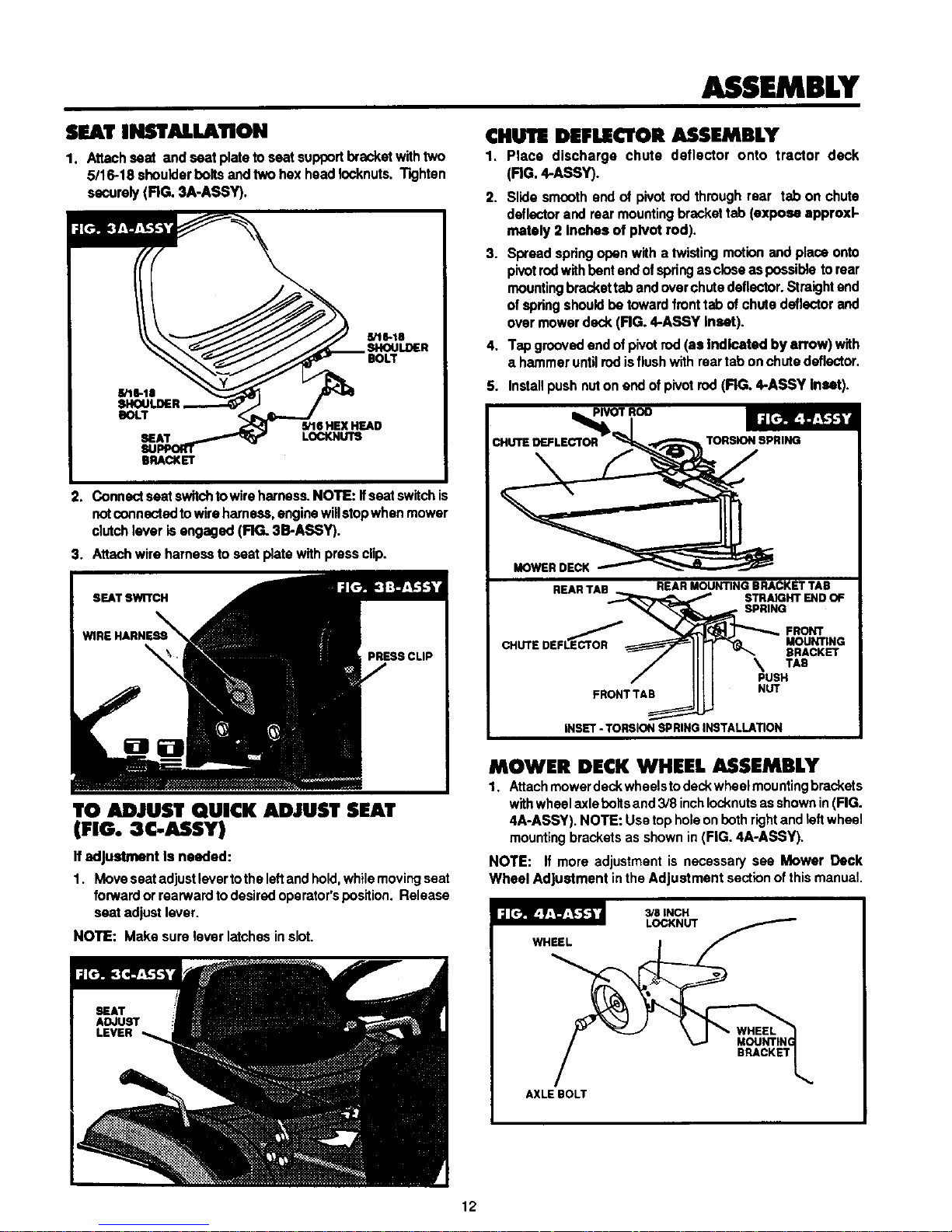
SEAT INSTALLATION
1. Attach seat and seat plate to seat supportbracket with two
5/16-18 shoulder bolts end two hex head Iocknuts. Tighten
securely (FIG. 3A-ASSY).
CHUTE DEFLECTOR ASSEMBLY
1. Place discharge chute deflector onto tractor deck
(FIG. 4-ASSY).
2. Slide smoothendof pivotrodthroughrear tabon chute
deflectorandrearmountingbrackettab (exposeapproxi-
mately 2 Inches ofpivot rod).
3. Spreadspringopenwithatwisting motionandplaceonto
pivotrodwithbentendof springascloseaspossibleto rear
mountingbrackettabandoverchutedeflector.Straightend
ofspringshouldbe towardfronttabof chutedeflectorand
overmowerdeck (RG. 4-ASSY Inset).
4. Tapgroovedandofpivotrod(as Indicatedby snow) with
a hammeruntilrodisflushwithreartabonchutedeflector.
S. Install push nut on end ofpivot rod (FIG. 4-ASSY inset).
2. Connect seat switohto wire harnass. NOTE: If seat switch is
notconnected to wire harness, engine willstop when mower
clutch lever isengaged (FIG. 3B-ASSY).
3. Attach wire harness to seat plate with press clip.
I_VOT Roo
CHUTE DEFLECTOR TORSION SPRING
MOWERDECK
REARTAB
REAR MOUNTING BRACKET TAB
STSAIGHT END OF
SPRING
LE_'_OR FRONT
CHUTE DEF MOUNTING
BRACKET
TAS
PUSH
FRONTTAB NUT
INSET- TORSION SPRING INSTALLATION
TO ADJUST QUICK ADJUST SEAT
(FIG.3C-ASSY)
If adjustment Is needed:
1. Move seat adjustlever to the left and hold,while movingseat
forward or rearward to desired operator's position. Release
seat adjust lever.
NOTE: Make sure lever latches in slot.
MOWER DECK WHEEL ASSEMBLY
1. Attach mower deck wheelsto deckwheel mounting brackets
withwheelaxle boltsand 3/8 inchIocknutsas shown in(FIG.
4A-ASSY). NOTE: Use tophole on both rightand left wheel
mountingbrackets as shown in (FIG. 4A-ASSY).
NOTE: If more adjustment is necessary see Mower Deck
Wheel Adjustment in the Adjustment sectldn of this manual.
f
AXLE BOLT
12
Page 13

ASSEMBLY
MOWER DECK INSTALLATION
1. Depress brake clutchpedal and set perking brake.
2. Place cuttingheightadjustmentlever in highestcutting
position.
NOTE: Besurefrontadjustmenteccentricsaremountedin the
secondhole from top of mowerdeckmountingbracketand
grooveon eccentricis pointedforward (FIG. 5-ASSY). Make
adjustmentsifnecessaryand proceed.
GROOVE
FRONT
ADJLBTMENI"
ECCENTRIC
MOWER DECK
MOUNTING
BRACKET
MOWER DECK LEVELINGADJUSTMENTHOLES
3. Place mower deck on rightside of tractor with chute away
from tractor.
4. Turn frontwheels all the way to the left.
S. Lift deck hitch.Slide mowerdeckhalfwayundertractor,
rotatingmowerdeckcounterclockwiseandloweringdeck
hitch.Slidemowerdeckforward undertractortoacentered
position.
6. Slide mower deck rearward. Connect mower deck
engagement cable to mower deck clutch spring
(FIG. 5A-ASSY). Besure openendof springispointeddown
(FIG. 5A-ASSY inset).
I LIWER ENGINE PULLEY
ENGINE
PULLEY
8. Remove hairpincottersandflat washer from the left and right
hand hanger pins (RG. 6-ASSY), remove hitch rod and
hairpincotter from front mounting bracket (RG. 6A-ASSY)
and lay allparts aside for later use.
9. Place cutting heightadjustment lever in lowest cuttingposi-
tion. NOTE: Be sure mower deck lift arms are on inside of
mower deck liftbrackets.
10. Slide left mower deck liftbracket on hanger pin of leftrearlift
arm and secure in place with flat washer and hairpincotter
removed in step 8. Repeat attachment assembly for right
rear mower deck liftbracket.
11.Place cuttingheightadjustmentlever in highestcutting
position.
HANGER PIN
MOWER DECK
LIFT BRACKET
REAR LIFT ARM
7. Slidedeck toward frontof tractor. Flex lower engine pulley
belt guides away from engine pulley and slipdeck drive belt
on lower engine pulley. Reposition belt guides to 1/16" from
pulley (FIG. 5B-ASSY).
12. L_t front of mower desk and place a 2 x 4 up on edge,
between front tires and underfront center of m,,-,er deck.
Thiswillbe used for leverage to raise and k)wermower deck
as needed to align front hitchmounting holes in step 13.
13
Page 14

ASSEMBLY
13. Lift front deck hitch. NOTE: Be sure ears of deck hitchare
to outside offront mounting brackat. Liftfrontof mower deck
with 2x 4 and align left hand deck hitch mounting hole with
lefthandfrontmountingbracket hole, installhitchrodthru left
hand holes and intoright hand front mountingbracket hole.
(RG. 6A-ASSY) NOTE: Once the 2 x 4 has been placed
under front edge of mower deck, cutting height adjustment
levercan be moved to a lower position ifneeded for easier
alignment of holes to install hitch rod.
14. Plane 2 x4 on side, underfront center of mower deck. This
willbe used for leverage to raise and lowerdeck as neadad
to align mounting holes in step 16.
15.Placecuttingheightadjustment leverin lowestcuttingposi-
tion.
16. Liftfront of mower deckwith 2 x4 and align righthand deck
hitch mountinghole with right hand front mountingbracket
hole, and install hitch rod thru deck hitch mounting hole.
Install hairpin cotter removed in step 8.
17.Check mower deck leveling and adjustment as required.
See Mower Deck Leveling Adjustment paragraph in
Adjustments section ofthis manual.
TO SERVICE ENGINE (FIG. 7-ASSY)
1. Place tractorso engine is in a level position.
2. Raise hood to gain access to engine. NOTE: Raise and
lower slowly to avoid personal injuryor damage to tractor.
3. Remove oil_i!lcep/dipstick. Clean dipstickwith a rag.
4. Check oil level. Use a funnel to add oil to the engine
crankcase, if the oil level is below the full mark. See Engine
Operating and Maintenance manual for properprocedure.
5. Reinstalloil fill cap/dipstick and tighten securely.
6, Checkto makesurethatsparkplugwire(s)is/areattached
tosparkplug(s).
7. Fill gas tank with clean, fresh lead-free gasoline with a
minimum rating of 77 octane. Low-lead or regular grade
leaded gasolines are acceptable. Do not mix oil with gaso-
line. Be certain container is clean and free from rustor other
foreign particles. Never usa gasoline that may be stale from
long periods of storage in the container.
_ ever fill the gas tank while the engine Is |
running or Is hot. Immediately wipe off any
J
spilled gasoline before attempting to start
engine.
TO SERVICE TRACTOR
1. Check tire pressure. Recommended operating tire pressure
is 10 to 14 pounds per square inch.Check side wall oftires
for manufacturer's maximum tire pressure. Do notexceed
thispressure.Equaltire pressure shouldbe maintained in all
tires.
2. Check all nutsand bolts to be sure none are loose.
3. Return totheTo Activate Battery paragraph inthissection
and complete the battery installation.
14
Page 15

OPERATION
The operation of this lawn tractor can
result in objects being thrown into the
eyes, which can result in severe eye darn-
age. Always wear safety glasses or eye
shieldswhile operating a lawntractor. We
recommend standard safety glasses or a
wide vision safety mask for over
spectacles.
Get toknowyourlawntractoranditscontrols.Be sureyou(or
any othw operator) have reed and understoodthe Safety
Pageslistedinthefrontofthismanual.
Your new lawn tractor will give years of service if cared for
properly. Never run intotrees, curbs, etc. Service regularlyand
store inadry area. Operate your lawntractor atslowspeeds until
you become familiar with the machine. Avoidsharp turnsat high
speed and uphillor downhillturns. Operate tractor carefully. Be
especially cautious on hills. When riding down inclines, keep
shiftcontrolinlowspeed withbrake-clutchpedal out.This allows
the engine to controlthe speed. Use brake forfast stopson hills.
KEEP MOWER CLEAN. Grass clippingsmay pack under the
mower deck due to the internal moisturecontent of the grass.
This accumulation of cut grass should be removed after each
mowing. Remove ignitionkey and scrape accumulationoffwith
a putty knifeor similar tool. Cleaning ofthe underside iseasier
if mower deck is removed. See Mower Deck Removal para-
graph inMalntenanca section of this manual. Remove dirtand
debris from engine area with a brushor cloth.
Do Not operate this tractor without a chute_
deflector in place.A lawn tractor can be dan-
gerous to operate If misused. On slopes, be
very cautious and avoid sharp turns to pre-
vent tipping or loss of control. NEVER carry
passengers. ,e
€ONTROLS
FIG. 1-OP shows all operating controls. The controls and their
functions are as follows:
• , I\1
L - Regulates engine and blade speed.
Engine should always be run at fast speed for best grass cut-
ting. NOTE: For models without a choke control button the
choke is regulated with the throttle control lever.
Ionitlon Switch - Used to startand stop engine. Turn key all
the way rightto 3rd position to start engine. When key is re-
leased after starting engine it will return to 2nd position. To
stop engine, turn kay to 1st position. Remove key to lock igni-
tion.
Headlloht Switch - Turns headlights on and off. With
engine running, push ON end of switchto turn headlights on.
To turn headlights off push OFF end of switch.
15
Page 16

OPERATION
Choke Control (if so eOUlDDed) - Used to start cold engine.
0
All Svmma Go Lloht (If so eouleoed_ - If this indicator islit,
the engine will not start.
1. Your clutch-brake pedal may not be fullydepressed.
2. The mower clutch lever may not be in the DISENGAGE
position.
Ammeter (If so soUlDDedl - Indicates whether bakery is be-
ing recharged when engine is running. If charge is not indi-
cated while engine is running at full throttle, have engine
charging system checked by an authorized engine service
dealer.
Transmission Coptrol Levtr - Used to select ground speed
ranges as well as direction of motion (forward-neutral-re-
verse). Forward speed ranges are labeled (1 -2-3-4-5) or (1-2-
3-d-S-S).
No. 1 range isslowest forward speed, usedfortraveling up
or down steep hills or for snow removal.
No. 2 range is used for cutting tail or heavy grass.
No. 3 range is used for average mowing conditions.
No. 4 range is used for light mowing.
\.
NO. 5 range is used for very light mowing on smooth flat
surfaces on a 6 speed. On a 5 speed it is used for
transportingthe unit.
No. 6 range should be used for transporting unit only,
l A Come toe full stop before changing dlrection_
• °fm°t=- )
_- Usedto lockbrake-clutch pedal inbrake
position. NOTE: Check gear shift position and know o p • r-
ating intentions before releasing brake.
1. Depress brake-clutch pedal fully, engaging brake.
2. Push parking brake lever forward and engage notch in
parking brake lever against main frame.
3. To release parking brake, apply pressure to pedal and
swing will release parking brake lever.
Brake-Clutch Pedal - This is a dual purpose control. Press
pedal halfway down to disengage clutch, it is usedforchanging
speed range or direction oftravel(forward or reverse). Release
pedalto engage clutch. With pedalcompletely depressed, brake
is applied.
16
Page 17

OPERATION
_- Usedtoengageordisengagethe power
tothemowerdeckbledes.Withmowerclutchlevermovedallthe
waytoDISENGAGE (rearward)position,bladesshouldstopin
asaleperiodoftime.UseDISENGAGEpositionwhenusingas
atractorfor yardjobssuchas pullinga miler, seeder,sweeper
or otheraccessories.
1,
Move lever slowly (Never"snap" the lever) toward front of
lawn tractor to engage power to the blades. It is important
to engage mower clutch leverwhile engine is running at full
speed.
2. Move lever slowlytoward rearof lawn tractor to disengage
power to blades and to apply blade brakes.
Mower clutch lever must always he In full DISENGAGE
position to start engine. Never place lever In ENGAGE
position until engine Is warmed up and operator Is on seat,
ready to start mowing. Always return lever to DISENGAGE
position before dismounting from tractor.
Cuttlna Haloht Adlustment Lever - Used to change height of
cut. The bottom position of lever is the lowest
cutting height and the top position isthe highest cuttingheight.
Other positions change height of cut approximately 1/2 inch
each,
1.
2.
Grasp lever (FIG.I-OP) with left hand and pullupward to
raise mower deck. You will hear a click sound as lever
passes to next height position.
Grasp leverwith lefthand and pull upward slightly.Depress
button on end oflever with thumb to release height adjust-
ment lever latch and lower mower deck to
desired height. Release latchbuttonand allow lever to latch
in place.
_ Blades will not stop Immediately. Keap"_
hands and feet from under the mower deck _
and away from the discharge chute. |
J
17
Page 18

OPERATION
TO START ENGINE
Read Operstlon section in this manual and Engine Operat-
Ing and Malntenanne manual before trying to start engine.
NOTE: Be sure engine ¢rancass Is filled to the full mark
before starting engine. Never run engine unless crank-
case Is properly filled with oil and dipstick Is tightened se-
curely.
IMPORTANT: When starting engine, the brake-clutch pedal
must be fully depressed and mower clutch lever must be in full
DISENGAGE positionto engage the lockout switches. The All
Systems Go light (If so equipped) on dash will glow and
engine will not crank unless these conditions are met.
Your lawn tractor is equipped with a seat switch. The
engine will stop If operator Is not firmly seated In
operator's seat when mower clutch lever Is engaged.
Lssnlng forward or to one side on the seat may cause the
engine to stop. To leave operstor's seat, the brake-clutch
pedal must be pushed all the way down and locked or
engine will stop.
To start engine proceed as follows:
1. Check to make sure fuel tank contains clean, fresh gaso-
line, and engine crankcase is properlyfilled with oil.
2. Depress and hold brake-clutch pedal all the way down.
Place shift lever in NEUTRAL position.
3. Place mower clutch lever in DISENGAGE position.
4. Place throttle control lever to FAST position.
S.
A warm engine willrequirelittleor no choking.For cold
startsplace'throttlecontrol leverinchokepositionor pull
chokecontrol out.Thiswilldependonthetypechokeyour
unitis equippedwith,
6.
Turn ignition key to START position. Release key when
engine has started. NOTE: Continuous cranking of more
than 15 seconds per minute can cause starterto overheat.
Allow starter to cool two minutes after prolonged cranking
of more than 15 seconds per minute.
7.
After engine starts, move throttle control out of choke
positionto desired engine speed or gradually push choke
control all the way in and move throttle control lever to
desired engine speed. This willdepend on the type choke
your unitis equipped with.
8. To stop engine, turn ignitionkey to OFF position.
I IMPORTANT
Move throttle to slow before turning Ignition off to
reduce muffler "POP".
Failure to do so will result In engine and exhaust
system damage.
If engine cranks but fells to start, proceed as follows:
1. Checkto make surefueltank contains clean, fresh gasoline.
2. Checkto make surespark plug(s)is/are tightened securely
intoengine and spark plug wire(s) is/are attached to spark
plug(s).
3. Carburetor adjustment may be necessary (see Engine
Operating and Malntanence manual).
If engine does not crank, check the following:
1. Be sure brake-clutch pedal is fully depressed and mower
clutch lever is in DISENGAGE position.
2. Be sure the battery has been serviced and charged.
3. Check fuse in red wire near beck of ignitionswitch.
LAWN TRACTOR OPERATION
Take a comfortable riding position on seat of lawn tractor
and startengine as outlined. After engine warm-up, move the
transmissioncontrol leverto a slowspeed position to get used
to your lawn tractor. After you become familiar with the opera-
tion of your tractor, move the transmission control lever to a
faster speed. With mower blades stopped, make your first run
in a large, open, level area. Learn to start, stop, and change
direction in this area. Once you learn to maneuver your lawn
tractor, move throttle control to FAST position. Slowly move
mower clutch lever to ENGAGE positionand start mowing. To
stop blades, move lever to DISENGAGE position. To stop
engine, movethrottlecontrolto SLOWposition,t urnignitionkey
to OFF position. CAU'nON: Disengage mower clutch lever,
set parking brake, stop engine, lower mower deck and
remove key before leaving operator's position. Always
dismount from left side.
Your lawn tractor Is equipped with a seat switch. The
• nglna will stop Ifoperator Is not firmly seated In operator's
seat when mower clutch lever is engaged. Leaning forward
or to one side onthe seat may cause the engine to stop. To
leave operator's seat, the brake-clutch pedal must be
pushed all the way down and locked or engine will stop.
18
Page 19

OPERATION
TO AVOID SERIOUS INJURY OR DEATH
Read Owner's'Operator's Manual(s).
Know location & function of all controls.
Keep guards, safety shields and switches In
place and working.
Remove objects that could be thrown by
blade(s).
_ Do not mowwhen chlldren &othersare around.
Never carry chlldren or passengers.
Look down and behind before and whlle back-
Ing.
Do not mow where machlns could tlp or sllp.
If machlne stops going uphill, dleangage
blade(s) and back down slowly.
Remove key when leaving machine.
Avoid sudden turns.
Go up and down slopes, not across.
J
MOWING HINTS
Forbestmowing results,engineshouldberunat fastthrottleand
groundspeed controlledby shift controllever position. Forward
speed ofthe lawntractor mustbe controlled in accordance with
thetypeand quantityofgrass being mowed. The moregrassthat
must be cut, the slower the speed forward should be. When
cutting light grass, the forward speed can be increased. By
observing the cutting actionofyour mower, you can determine
how fast you can travel.
Your mower may tend to leave unmowed stripswhen longand
tender grass isbeing mowed. Tender grass has a high intemal
moisture content and is easily depressed by the lawn tractor
wheels, and may not always spring back in time to be cut. To
overcome this condition, we advise mowing the lawn in a
counterclockwise direction, overlapping previous cut, which
allowsthe liftingaction ofthe rotatingblades toliftthe grass into
the cutting path.
The rear wheals are driven by a transaxla, similar to an
automobile differential. This makes short turns po_s_e and
prevents marring of the lawn. It is possible to spin the drive
wheels of the lawn tractor under adverse conditions. When one
wheel slips, shift your weight over this wheel to obtain more
pullingpower. Your lawntractor isvery maneuverable and can
be reversed to back out ofdead ends. CAUTION: Dlcengsga
mower blades before backing up. Carefully check area
behind tractor for children or pets before becking up.
19
Page 20

MAINTENANCE
The warranty on this lawn tractor does not cover items that
have been subjected to operator abuse or negligence. To
receive full value from the warranty, operator must maintain
lawn tractor as instructed in this manual. The following Main-
tsnanca Check List is supplied to assist operator to pmpedy
maintain lawn tractor. This is a check list only.
Adjustments referred to will be found in Adjustments section
ofthis manual.
BEFORE STORAGE
BEGINNING EACH SEASON
EVERY 100 HOURS
EVERY 50 HOURS
EVERY 25 HOURS
MONTHLY
FREQUENTLY
AFTER FIRST 5 HOURS
MAINTENANCE CHECK LIST
SERVICE RECORD
FILL IN DATES
AS YOU COMPLETE
REGULAR SERVICE
BEFORE EACH USE
CheckEngineOilLevel
ChangeEngineOil
ChangeOil Filter(ifsoequipped)
CleanAirFilter
ChangeSparkPlug(s)
ReplaceAir FilterPaper Cartridge
CleanAirScreen
InspectMuffler/SparkArrestor
ReplaceFuelFilter
CheckBatteryFluidLevel/Recharge (i
CleanBatteryandTerminals
AdjustMotionDr_veBeltTension
CheckBrakeOperation
CheckTransmissionCooling
CheckTire Pressure(10-14 Ibs)
AdjustMowerDeck Belt
Sharpenor ReplaceMower Blades
Checkfor LooseFasteners
CleanLawnTractor
See LubricationChart
i I
I I
I
I
I
I
NOTES: 1, Change more often when operating under a heavy load or in HIGH temperatures. (90°and above)
2. Service more often when operating in dirtyor dusty conditions. 3. Replace more often when mowing in sandy soil.
• _ LUBRICA110N
At no time during maintenance or adjustments
can the lawn tractor be lifted more than 20
Inches from level position without taking the
_ following precautions:
1. Remove gasollna from tank and run engine
until carburetor is dry.
2. Remove battery. (see BATTERY REMOVAL
paragraph In MAINTENANCE section.)
3. Remove oil from crankcase.
For lubrication frequency see Maintenance Check List. For
lubrication points and type of lubricant see Lubrication
Chart. The transmission has been lubricated for life.
2O
Page 21

MAINTENANCE
CLEANING LAWN TUCTOR
Grass clippings may pack under the mower deck due to
the internal moisture content of the grass. This accumulation
of cut grass should be removed a:ftereach mowing. Remove
ignitionkey and scrape accumulation off with a putty knife or
similartool. Cleaning of the undersideis easier if mower deck
is removed. See paragraph Mower Deck Removal. Remove
dirt and debris from engine area with a brush or cloth.
ENGINE MAINTENAHCE
See Engine Operating end Maintenance manual for mainte-
nance instructions.
MAIHTAIN THE AIR FILTER
The air filter should be cleaned and/or replaced every 25
hours of operation under normal operating conditions; more
often under dusty conditions. To clean the air filter see Engine
OperaUng and Maintenance manual.
SPARK PLUG MAINTENANCE
Spark plug should be checked periodicallyfor excessive car-
bon and gap. The spark plug gap should be checked with a
wire feeler gauge and set at .030 inchas shown inthe Engine
Operating and Maintenance manual.
TO CHANGE CRANKCASE OIL
(FIG. 1-MAINT}
Change crankcase oil after first 5 hours ofoperation and every
25 hours thereafter, Sea Engine Operating and Mainte-
nance manual for proper procedure.
Your unit is equipped with an oil drain plug or an oil drain
valve. Usa procedure that pertains to yourunit.
For oll drain plug:
1. Placea flatbottom2 quartcontainerunderoi!drainplug.
NOTE: It may be necessary to raise left side of lawn tractor
(with blocks under left wheels) to get proper drainage.
2. Removeoildrainplugtodrainoil. NOTE:Oilfillcap/dip_tick
should be loosened to serve as an air vent.
3. Reinstalloil drain plug, remove oilfill cap/dipstick and refill
crankcase.
4. Reinstalloil fil! cap/dipstick.
For oil drain valve:
1. Place a flatbottom2 quartcontainer beneath oildrainvalve.
NOTE: The user has the option ofconnecting a vinyl hose
toport end of valve inorder todrain usedoilintocontainerfor
disposal.
NOTE: Itmaybenocessary to raise leftsideoflawntractor(with
blocks under left wheels) to get proper drainage.
2. Turn oil drain valve countemlockwisa and pull to drain oil.
NOTE: Oil fillcap/dipstickshouldbe loosened to serve as an
air vent.
3. Tocloseoildrainvalvepushandturnclockwise.Removeoil
fill cap/dipstick and refill crankcase as outlined in
Engine Operatingand Maintenance manual.
4. Reinstall oil fillcap/dipstick.
21
Page 22

MAINTENANCE
LUBRICATION CHART
Orientation view only. Do Not stand on end. WIPEGREASEON
SECTOR GEAR AND
STEERING GEAR
AXLE(IFSOE(:UIPPED)_r_
_ ONBOTHSIDES
_ , ' B_T_RIO_F ON BOTH SLUES
f _" USE SAME TYPE OIL USED IN CUNKCASBA OOOD GUDB OF CUP GREASE '_ EVERY 2S NOURS OF OPEUTION
HEADUGHT BULB REPLACEMENT
(FIG. 2-MAINT)
NOTE: Du nut remove the plastic headlamp lens when
replacingthe headlight bulbs.
1. Lift hood.
2. Turn the headlight harness (holding the bulb) 1/4 turn
counterclockwise (to the left) and remove.
3. Pull the bulb out (do not unscrew). Push in new bulb.
4. Replace the headlight harness and turn a quarter turn
clockwise to the right to lock in place.
TO REMOVE
BULB
HEADLIGHT
4ARNESS
22
Page 23

MAINTENANCE
Whenyou charge the battery,do not smoke. I
Keepthe batteryaway from any sparks. The I
fumes from the battery acid can cause an|
explosion. )
BATTERY MAINTENANCE
When starter operates properly and battery connections are
clean and tight but cranking difficulty is experienced, battery
may not be charged. Batteryshould be taken to an authorized
service station and tested.
If engine will not start rightaway under normalcranking speed,
continued cranking will run down the battery and may cause
damage to starter. Check ignitionand fuel systems and correct
any faults.
The battery should be kept clean. If the top has an accumula-
tion of dirt Drgrease, remove the battery from vehicle forclean-
ing. The battery should be cleaned with a mild solutionof bak-
ing soda and water. Brush this on, keeping vent plugstightly in
place to prevent any solution from entering the cells. Allowso-
lution to work for a few minutes, then rinse with clean water
and wipe battery dry. if battery terminals are corroded, clean
with a wire brush and coat terminals with petroleum jelly. Be
sure to reinstall battery in the same position and properly
reconnect battery cables (red to positive, black to negative).
Proper care will lengthen battery life. When replacement
becomes necessary, use battery of same size and type for
continued trouble-free service (see Repair Parts section/
manual).
t_k Always dlaconnect negative (black) cable flrst."_
Removing positive cable first can result In|
sparks If the wrench touches any metal sur-|
face. Be sure battery hold-down bracket dcas/
, not touch batterytermlnala and cauca a spark.J
BATTERY REMOVAL (FIG.3-MAINI')
1. Raise seat and disconnect negative (black) batten/cable
and move away from terminal.
2. Pullaway batterycable boot (If so equipped) from positive
(+) battery terminal. Disconnect positive (red) battery cable
from battery.
3. Remove plastic wing nutfrom battery hold-downrod.
4, RBmove battery hold-down bracket and hold-down rod.
5. Liftbattery out of tractor.
6. Reinstall battery (see Battery Installation paragraph).
NEGATIVE (-) BLACK
BATTERY CABLE
BATTERY HOLD-DOWN BRACKET
1/4 X 3/4 INCH HEX HEAD SCREW
S LOT
BATTERY t#OOT
(IF SO EQUIPPED)
BATTERY
f .............
PC_SITIVE (+) RED
BATTERY BA'I-rE Ry CABLE
1/4X 3/4 INCH HEX HEAD SCREW
PLASTICWINGNUT
"(-) BATTERYTERMINAL
NEGATIVE (-) BLACK BATTERY
CABLE
BATTERY
HOLD-DOWN
/ LARGEHOLE
POSITIVE (+) RED BATTERY TERMINAL
BATrERY BOOT
(IF SO EQUIPPED)
POSITIVE (+) RED BATTERY CABLE
CUT-AWAYVIEW FROM RIGHT-HANDSIDE OF TRACTOR
23
Page 24

MAINTENANCE
_ Ahvoys connect postt_e (red) cable first. Con- i
-%
ncctlng ncgat beecable first canresult insparks
J
If the wrench touches any metal surface. Be
sure battsry hokJ-down brackst does not touch
battery terminals and cause a spark
BATTERY INSTALLATION
(Fie.3- UNT)
1. Raise seat plate and place battery back into tractor with
positive (+) terminal toward right side of tractor.
2.
3.
4.
Place battery hold-down bracket through slot in back of
console. NOTE: Turn bracket to side, place through slotin
console and rotate upright.
Place hook end of battery hold-down rodthroughshift lever
hole in main frame and hook into small hole in front of
battery.
Place threaded end of hold-down red through loop in
bracket and secure with plastic wingnut.
NOTE: Tighten with pliers ifnecessary.
5. Attach positive(red) battery cable topositive (+)terminalon
, batterywith a 1/4 X 3/4 inchhex head screw and a 1/4 inch
keps nut.
6, Slide battery boot (if so equipped) up cable and over
terminal.
7. Attach negative (black) battery cable to negative (-)
terminal on battery with a 1/4 X 314 inch hex head screw
and a 1/4 inc_keps nut.
BELT GUIDES
This unitis equipped with belt guides (FIG. 4-MAINT) located
next to engine pulley. These belt guides are angle rods se-
cured to main frame. The guides are moved (by loosening
Iocknuta) before replacing belts. When repositloning (after
new belt Installation) allow 1/16 inchgap between guide and
pulley.
LAWN TRACTOR DRIVE BELT
REPLACEMENT
Your lawn tractor uses v-belts made of special compounds. If
any belt becomes worn or breaks, replace with original
equipment belt (see Repair Parts section/manual),
NEVER USE A SUBSTITUTE. To replace tractor drive belt
proceed:
1. Remove mower deck. Sea Mower Deck Removal para-
graph.
2,
3.
Depress brakeclutchpedal and set parking brake.
Loosendutch idlerpulley mountingscrewenough to allow
belt to be removed between pulley and retainer (FIG. 5-
MAINT).
4. Remove cotter pinthat attaches shif?lever totransaxle and
remove shift lever from transaxle shift bracket,
(FIG.4.MAINT)
5. Loosen transaxle pulley belt guide.
6. Removebaif from transaxlepulley(rollover top oftransexte
pulley).
7.
tt.
9.
10.
11.
12.
13.
Remove belt from engine pulley and replace with new
originalequipmentbelt in reverseorderor removal. NOTE:
Be sure drivebeltisinstalledtoinsideofupperengine pulley
belt guide and transaxle pulley belt guide.
Reinstall shiftlever to transaxid shiftbracket withcotterpin
removed in step 4.
With parking brake lever in 3rd notch, secure belt retainer
on dutch idler pulley(RG. 5 MAINT) NOTE: Belt retainer
should point to where running board meets main frame.
Makedrivebeltadjustment.SeeLawn TractorDriveBelt
AdjustmentparagraphinAdjustmentssection.
Checktractorbrakeadjustment.Makeadjustmentifneces-
sary.See Lawn Tractor BrakeAdjustmentparagraphin
Adjustmentssectionof thismanual.
If blade drive belt needs replacement, do so before
reinstallingmower deck assembly.
Reinstall mower deck in reverse order of removal.
LOWER ENGINEPULLEY
24
Page 25

MAINTENANCE
MOWER DECK REMOVAL
1. Set parldng brake.
2. Movemower clutchleverto disengagedpositionand mower
deck to lowest cut position.
3. Turn thefront wheels allthe way tothe leftto allowthedeck
hitch to slide past the rightfront wheel.
4. Remove hairpin cofterfrom mower deck hitchrodatfrontof
deck (RG. 6A,MAINT). Remove hitchrod and lowerdeck
hitch.
5. Remove hairpincotter and flatwasherfrom right hand
hangerpin.Sliderightliftbracket offrearliftarm.
6. Removehairpincotterand Ifatwasherfromthe lefthand
hangerpin.Slidetheleftliftbracketoffrearliftarm.
7. Slidedecktowardfrontoftractor.
8,
Flex lower engine pulley belt guides away from engine
pulley and slip mower deck drive belt off lower engine
pulley. Note original position of lower engine pulley belt
guides (RG.4-MAINT). Correct distance between guide
and pulley is 1/16".
g. Disconnect mowerdeck engage mentcable (FIG. 7-MAINT)
from mower deck clutchspring.
10. Deck can now be pulledout from rightside of unit.
11. Install mower (see Mower Deck Installation paragraph in
Assembly section of this manual).
BLADE DRIVE BELT REPLACEMENT
(FIG.:r. UNT)
1. Remove mower deck (see Mower Deck Removal para-
graph inthis section).
2. Remove mower deck belt guards.
3. Note position of belt retaineron idler pulley #1 and #2 so
that retainer can be repositioned properly after belt
installation.
To remove long belt:
4. Loosen nut on idler pulley #1 enough to slip belt
between pulley and belt retainer.
5. Remove old belt and replace with a new original
equipment belt. NOTE: Check condition of short belt. If it
needs to be replaced do so at this time.
To remove short belt:
6. Loosen nut on idler pulley #2 enough to slip belt
between pulley and belt retainer.
7. Pull brake arm away fromcenter quill assembly enough to
slip belt off of pulley.
8. Remove old belt and replace with a new original
equipment belt.
After replacing long and short belts:
9. Adjust belt retainers and ratighten nuts on idler pulley #1
and #2.
10. Adjust belt guide near center quillto 1/16"from pulley.
11. Adjust belt guide near rightblade quill 1!16" from pulley.
12. Reinstall belt guards.
13. Reinstall mower deck assembly.
14. Adjust belt as described in paragraph Blade Drive Belt
Adjustment in Adjustments section.
HANGER PIN REARLIFTARM
MOWER DEC
UFT BRACKET
FLAT WASHER
MOWER CLUTCH
CABLE
ASSEMBLY
MOWER DECK BELT
CLUTCHCABLE _UARD)
SPRING SHORTBELT
BELTGUIDE
BELT
HAIR PIN
COTTER
25
Page 26

MAINTENANCE
8LAM (R6. 8. uml
The cutting blades should be sharp and well-balanced to run
smoothly. Blades should have correct amount of "lift" for
proper cutting anddischarge of clippings. Lift iscreated by up-
turned bent tip edges of blade ends. As cutting edges of
blades wear, the bent tip edges also wear, decreasing blade
lift, resulting in decreased cutting ability. It is recommended
blades be replaced when upturned ends show signs ofwear.
IMPORTANT: Stop engine end Inspect blades at once If
you strike any solid unyielding object. Check to make
sure blade mounting screws are tight. To remove blades:
1. Remove mower deck. See Mower Deck Removal pare-
graph.
DO NOT handle blades with bare hands. Weerl
gloves or wrap blade with newspaper or other|
material while removing or Installing blade. ]
J
2. With a 9/16 inch wrench, remove blade mountingscrews by
turningscrews counterclockwise.
When replacing blades, besure allparts are reassembled in
proper order (see Repair Parts section/manual) or severe
vibration will occur. Bent tip edges of blades must be up
toward top ofmowerdeck or blades willnotcut.NOTE: Make
sure blade mounting screws ere tightened securely. We
recommend using a 10 inchwrench or a torque wrench. If a
torque wrench is used, torque blade mounting screws to
between 30 and 35 foot pounds.
3. Reinstall mower deck.
ToSUAP.PmBLAHS(RO.9-J Uml
Care should be taken to keep blades balanced. An unbal-
anced blade willcause excessive vibration and eventual dam-
age to mower and engine.
1. Blade can be sharpened with a file or on a grinding
wheel. Do not attempt to sharpen while on mower.
2. Place center hole of blade over heed of the nail or end
of a screwdriver clamped horizontally in a vice. If blade
is balanced, it should remain in a horizontal position. If
either end of the blade moves downward, sharpen
heavy end untilthe blade is balanced.
BLADE
CENTERHOLE
BENTTIP EDGE
BLADE
SHARP
SPRING
,WASHERS
SCREW
26
Page 27

Keephands,feet,hairandIooeeclothlngaway"_
from any moving parts on engine or lawn|
tractor when making any adjustments that|
require engine to be running. DO NOT carryl
passengers. ,)
Located beneath the main frame are two v-belts` One v-belt
(lawn tractor drive belt) transmits power to the transaxle
which, in turn transmits power to the rear wheels. The other v-
belt transmits power to the mower blades.
Located on the mower deck is a clutchthat disengages power
to the blades and a deck leveling adjustment.
Before any adjustments are made, it is necessary that you
understand the function of the brake, clutch, and the brake-
clutch pedal. The pedal disengages the clutchwhen partially
depressed and applies the brake when fully depressed.
Adjustment of the lawn tractor drive belt and brake must
be synchronized so brake does not grab before clutch
disengages. An incorrect adjustment causes brakes to grab
or hold while power is being transmitted to the rear wheels.
Lawn tractor will try to move with brake applied.
To replace drive belts, you must remove mower deck,
Removal of deck isn't necessary for other adjustments, but it
several adjustments are needed, it will be more convenient if
deck isremoved.
ADJUSTMENTS
Depress brake-clutch pedal far enough to latch parking
brake inthird notch (insert, RG.2-ADJ).
At no time during the adjustment or repairs
can the lawn tractor be lifted more than 20
Inches from level position without taking the
_ following precautions:
1. Remove gasoline from tank and run en-
gine until carburetor Is dry.
2. Remove bsttery (see BAI"rERY REMOVAL
paragraph In MAINTENANCE eectlon of this
manual).
3. Removeoll from crankcase.
1.
2. Loosen clutchingidlerpulley (RG.2-ADJ) mounting screw.
3. If brake-clutch pedal was too far forward slide idler
pulleyintoward engine pulley. If pedal was too farrearward
slide idler pu!ley out away from engine pulley.
4. Retighten idler pulley mountingscrew. NOTE: Belt retainer
should point toward position where running beard meets
main frame (RG.2oADJ).
5. Release brake.clutch pedal and recheck pedal for proper
position. Readjust if necessary.
6. Check lawn tractor brake adjustment as outlined in para-
graph Lawn Tractor Brake AdJustmanL
LAWN TRACTOR DRIVE BELT
ADJUSTMENT
The drive belt is kept tight by a spring attached to the brake-
clutch pedal assembly. When drive belt is properly adjusted,
brake.clutch pedal in fullyreleased position should appear as
shown in FIG.I-ADJ. ffdrive bait requires adjustment, adjust
as follows:
BRAKE-CLUTCH
PEDAL_
LAWN TRACTOR BRAKE ADJUSTMENT
Your tractor is equipped with an adjustable disc brake
mounted on the transexls`
To checkbrake operation:
1. Stoptractorons hardflatsurfaceandturnoffengine.
2, Place shift control lever in (NEUTRAL) position.
3. Depress brake-clutchpedal enoughto latchperking brake in
2nd notch (FIG. 2-ADJ).
4, Try topush tractor. Ifyou are unable to push tractor,brake
istco tight and should be loosened (see To adjust tight
brake).
5. Depressbrake-clutch pedal enough to latch parkingbrake in
4th notch (FIG. 2-ADJ).
6. Tryto push tractor, if you are able to push tractor, brake is
too loose and shouldbe tightened (see To adjust loose
brake).
27
Page 28

LAWN TRACTOR BRAKE ADJUSTMENT
(CONT.)
To adjust loose brake:
1. Placoshiftcontrollever in (NEUTRAL) position anddeprass
brake-clutch pedal enough to latch parking brake in 4th
notch.
2. Turn brake adjusting nut clockwise until you cannot push
tractor.
3. Rechecktractorbrakeadjustmentas outlinedinTo check
brake oporstlon.
To adjust tight brake:
1. Placeshiftcontrolleverin(NEUTRAL)positionanddepress
brake-clutchpedal enoughto latchperking brake in 2nd
notch.
2. Turn brake adjustingnutcounter-c!ockwiseuntilyoucan
pushtractor.
3. RechecktractorbrakeadjustmentasoutlinedinTo check
brakeoperation.
Duringtractor operation, check for stoppingdistance. If tractor
requires more than six (6) feet for stopping distance at high
speed in highest gear, the brake must be adjusted (see Lawn
Tractor Brake Adjustment above).
3.
4.
5.
6.
7.
8.
9.
ADJUSTMENTS
Measure height from the bottom of the left hand blade
mounting screw to ground. Height should be 3-1/2 inches
with mower deck set in high cut.
If adjustment is necessary, block up mower deck with a
2 x 4 and set height adjustment leverto lowcut position.
Remove hair pin cotter (FIG. 4-ADJ) from clevis pin.
Remove clevis pin.
Loosen hax jam nut on cable above clevis. Turn
clevis clockwise to raise mower deck. Turn counterclock-
wise to lower deck. Each 1-1/2 complete turn of clevis
represents approximately 1/8 inchchange in the height of
mower deck.
Reinstall clevis and clevis pin. Return height adjustment
lever to highcut positionand remove wood blockfromunder
deck.
Check mowerdeck height measurement. If measurement is
correct reinstall hairpin cotter and tighten jam nut. If more
adjustment is necessary repeat preceding instructions.
Check and adjust level of mower deck as outlined in para-
graph Mower Deck Leveling Adjustment.
MOWER DECK HEIGHT ADJUSTMENT
Before making any mower deck height adjustments, check air
pressure in all four tires. All tires must be p_operly inflsted.
Recommended air pressure is 10 to 14 pounds per square
inch. Check side wall of tire for manufacturer's maximum tire
pressure. Do not exceed this pressure. Equal tire pressure
should be maintained in all tires.
Main frame on lawn tractor should be level across the front
from left side to rightside. If main frame will not sit level, the
two outside axle mounting screws may be too tight. The two
outside mounting screws must be loose enough to allow front
axle to pivot. NOTE: DO NOT loosen center mounting
screw.
1. Park lawntractoron firmlevel surfase, suchas a drivewayor
garage floor.
2. Place mower deck height adjustment lever in high cut
position.
MOWER DECK WHEEL ADJUSTMENT
Mower deck wheels may be adjusted to four positions. Both
wheels must be adjusted to the same position. NOTE: Do Not
adjustwheels to support mower deck while mowing or uneven
cuttingwill rasult.
To adjust mower deck wheels proceed:
1. Park lawn tractoron firm levelsurface, such as a driveway or
garage floor.
2. Set cutting height adjustment lever to lowest anticipated
cutting height.
3. Adjust wheels to a pesiticn 1/8 inch to I/4 inch above the
ground. Change wheel height adjustment by relocating
shoulder bolt in one of four positions in wheel mounting
bracket.
28
Page 29

ADJUSTMENTS
MOW.DECK/
MOUNTING BRACKET MOWER DECK LEVELING
ADJUSTMENT HOLES
MOWER DECK LEVEUNG ADJUSTMENT
Before making any mower deck leveling adjustments, check
air pressure in allfour tires. Recommended air pressure is 10
to 14 pounds per square inch. Check sidewall of tires for
manufacturer's maximum tire pressure. Do not exceed this
pressure. Equal tire pressure should be maintained in all tires.
Tractor main frame should be level across the front from left
side to right side. If mainframe will not sit level, the two outside
axle mounting screws may be too tight. The two outside
mounting screws must be loose enough to allow front axle to
pivot. NOTE: DO NOT loosen center mounting screw.
The mower deck level can be adjusted from front to back and
from side to side. Always adjust front to back level first.
1. Park tractor on firm level surface, such as a driveway or
garage fidor.
2. Check andadjustheightofmower deck asoutlinad inMower
Deck Height Adjustment paragraph.
3. Place mower deckcutting height adjustment isver inmidcut
positidn. NOTE: All adjustments will be made from mid cut
position.
To adjust front to back level.
4. Measure height, from level surface, ofrightside blade tipsat
front and rear of mower deck (be sure all tires are
properly Inflated). Ifdistances are equal or not more than
1/8 inch lower in front, no front to back adjustment is
necessary.
5. Ifadjustment is necessary, loosen front eccentric mounting
screws (FIG. 5-ADJ) and turn front adjustment eccentric
clockwise or counterclockwise as required. NOTE: When
grooveon eccentric ispointed straight forward (FIG. 5-ADJ
inset)frontof deck isatthe lowest!:)oint.Turnboth accentrics
so grooves are pointing same direction (upward or down-
ward). Always keep grooves toward front of lawn tractor.
If more adjustment is necessary, front of mower deck may be
raised or lowered by relocating eccentric mounting screws in
higheror lower hole positionon mower deck mountingbracket.
6. Hold eccentric with a wrench while tightening eccentric
mountingscrews securely.
To adjustside toside level.
7. Measureheight, fromlevelsurface, ofleftandrightbladetips
at outside edge of deck. If blades are equal or not morethan
1/8 inchdifferent, noside to side adjustment is necessary.
8. Ifadjustmentisnecassary,loosen rightsideaccentricmount-
ing screw (RG. 6-ADJ) and turn eccentric clockwise or
counterclockwise as required to level mower deck. NOTE:
When grooveineccentric is pointing downward, rightsideof
deck isin idwest position.When groove ispointing upward,
rightside of deck is in highest position.
9. Hold eccentric with a wrench while tightening right side
eccentric mountingscrew securely.
ECCENTRIC
IDLER
PULLEY
FRONTOF DECK
BLADE DRIVE BELT ADJUSTMENT
When mower blade drive belt slips and blades will not re'/to
full speed while mowing, the blade drive belt should be tight-
ened. To adjust:
1. Place mower clutch leverin disengaged position.
2. Loosen idlerpulley hex nut (FIG. 6-ADJ).
3. Slideidler pulleytoward centerof deckto tightenbelt. NOTE:
Only a small amount of movement shouldbe required.
4. Retightsn hax nuton idler pulley.
5.
To check adjustment start engine and run engine at (FAST)
throttlesetting. Engage mowerclutch lever and allow suffi-
cient time for blades to run to full speed, then disengage
mower clutch lever.Blades shouldstopwithinafew seconds
and remain stopped. If blades do not stop or tend to creep,
adjustment is too tight.
6. To loosen bladedrivebelt,roverse step 3above. NOTE: The
left blade drive belt has noadjustment.
29
Page 30

ADJUSTMENTS
STEERING GEAR ADJUSTMENT
(FIG. 8.ADJ)
If excessive play develops in the steering, adjust pinion and
sector gears as follows:
1. Slightly loosen sector gear mounting screw under main
frame.
2. Turnsectorgeareccentricto movesectorgearforwardor
backwardas required.
3. Hold sector gear eccentric with wrench while tightening
mounting screw securely.
BLADE BRAKE ADJUSTMENT
1. Right hand and canter quill brake pods should completely
clearquill assembly pulleys when the mower clutch lever is
in the engaged position.
2. Ifthe canter quill brake pod does not clearthara istoo much
slackinthe mowerclutch engagement cable. The springcan
be repositionad on the idler arm extension in an aitamate
holeorthe cable conduit end can be adjusted at the pulley
support bracket to eliminate excess slack in engagement
system. _.
3. Inthe disengagad position there shouldbe notension on the
mower deck clutch spring. There should be only enough
slackas to allow approximately 1inch total sideways move-
mentofthe cable-end/spring-end junction. Thisensuresthat
the brake isexerting proper pressure to stop the center and
left hand blade effectively.
4. Check adjustment on righthand brake pad. Locknuton end
of brake rod should be approximately 1/8 inch from brake
pad mounting Ixscket with mower clutchlever disengaged
and right hand brake pad against quillpulley. Adjust Iocknut
if necessary.
ENGINE ADJUSTMENTS
See Engine Operating and Maintenance manual for engine
adjustment instructions.
3O
Page 31
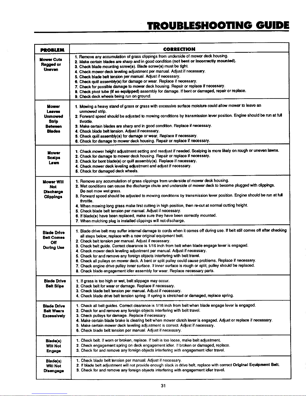
TROUBLESHOOTING GUIDE
PItOBIUEM
MowerCuts
R_wed or
Uneven
Mowor
Leaves
Unmowed
Strip
Between
Blades
Mower
Scalps
Lawn
Mower Will
Not
Discharge
Clippings
Blade Drive
Belt Comes
Off
Oudng Use
CORRECTION
1. Remove any accumulation of grass clippings from underside of mower deck housing.
2. Make certain blades are sharp end in good condition (not bent or Incorrectly mounted).
3. Check blade mounting screw(s). Blade screw(s) must be tight.
4. Check mc_ver deck leveling adjustment per manual. Adjust if necessary.
S. Check blade belt _slen per manual. Adjust if necessary.
6. Check quill assembly(s) for damage or wear. Replace if necessary.
7. Check for possible damage to mower deck housing. Repair or replace if necessary.
8. Check pivot tube (if so equipped) assembly for damage. If bent or damaged, repair or replace.
9. Check deck wheels being run on ground.
1. Mowinga heavystandofgrass or grasswithexcessivesurfacemoisturecouldallowmowerto leave an
unmowedsthp.
2. Forwardspeedshouldbe adjustedto mowingconditionsby fransmlssionlever position.Engineshouldbe runat full
throttle.
3. Makecertain bladesaresharpendin goodcondition.Replaceifnecessary.
4. Checkbladebelttension.Adjustifnecessary.
S.Checkquill assembly(a)fordamageorwear. Replaceif necessary.
6. Checkfor damagetomowerdeckhousing.Repairor replaceif necessary.
1. Check mower height adjustment settng and readjust if needed. Scalping is more likelyon rough or uneven lawns.
2. Check for damage to mower deck housing. Repair or replace if necessary.
3. Check for bent blade(e) or quid esaembly(a). Replace if necessary.
4. Check mower deck leveling adjustment and adjust if necessary.
6. Check for damaged deck wheels.
1. Remove any accumulation of grass clippings from underside of mower deck housing.
2. Wet cendidons can cause the discharge chute and underside of mower deck to become plugged with dippings.
Do not mow wet grass.
3. Forward speed should be adjusted to mowing conditions by transmission laver position. Engine should be run at full
throttle.
4. When mowing long grass make firstcutting in high position, then re-out at normal cutting height.
5. Check blade belt tension per manual. Adjust if necessary.
6. If blade(s) have been replaced, make sure they have been correctly mounted.
7. When mulching plug is installed clippings wLIInotdischarge.
1. Blade drive belt may suffer internal damage to cords when it comes off during use. If belt stillcomes off after checking
all steps below, replace with a new original equipment belt.
2. Check belt tension per manual. Adjust if necessary.
3. Check belt guide. Correct clearance is 1/16 inch from belt when blade engage lever isengaged.
4. Check mower deck leveling adjustment per manual. Adjust if necessary.
S. Check for end remove any foreign objects intederlng with belt travel.
6. Check all pulleys on mower deck. A bent or split pulley could cause problems. Replace if necessary.
7. Check engine drive pulley inner surface. If inner surface is rough or spill pulley should be replaced.
8. Check blade engagement idler assembly for wear. Replace necessary parts.
Blade Drive 1. If grass is too high or wet, beltslippage may occur.
Belt Slips 2. Check belt for wear or damage. Replace if necessary.
3. Check blade belt tension per manual. Adjust if necessary.
4. Check blade drive belt tension spring. If spring is stretched or damaged, replace spdng.
Blade Drive 1. Check all belt guides. Correct clearance is 1116 inch from belt when blade engage lever is engaged.
Belt Wears 2. Check for end remove any foreign objects interfering with belt travel.
Exceuively 3. Check pulleys for damage. Replace if necessary.
4. Make certain blade brake is clearing belt when mower clutch lever is engaged. Adjust or replace if necessary.
5. Make certain mower deck leveling adjustment iscorrect. Adjust if necessary.
6. Check btade belt tension par manual. Adjust if necessary.
Blade(s) 1. Check belt1 if worn or broken, replace. If belt is too loose, make belt adjustment.
Will Not 2. Check engagement spring on deck engagement idler. It broken or damaged, replace.
Engage 3. Check for and remove any foreign objects interfering with engagement idler travel.
Blade(e) 1. Check blade belt tension per manual. Adjust if necessary.
Will Not 2. If blade belt adjustment will not provide enough slack in drive beif. replace wi_ correct Original Equipment Belt.
Disengage 3. Check for and remove any foreign objects interfering with engagement idler ravel.
31
Page 32

TROUBLESHOOTING GUIDE
PROBLEM CORRECTION
Ex_emn
Vibmtimt
Occurs When
Blade Is
Engaged
UnitDrive
Belt Slips
Unit Drive Belt
SqmmlsWhen
BrakeIs Applied
Unit Drive Belt
Comes Off
During Use
UnitWill Not
Propel Itself
When Clutch
Is Engaged
1. Check blade(s) and make certain they are not bunt, out of balance or inose. Replace if necessary.
2. Check buif for bum spots or itreguladfiee that might cause vibrafion. Replace if necessary.
3. Check quill assembly(s) for damage or wuar. Replace if necessary.
4. Check for worn or damaged bladeengagement parts. Repair or replace if necessary.
5. Check engine drive pulley inner surface. If inner surface is rough or split, pulley should be replaced.
6. Check under side of mower deck housing for accumulation of dipplngs. Remove accumulated clippings.
7. Check for loose or damaged engine mounts. Tighten or replace as necessary.
g. Check Made belt tension per manual. A_ust if necessary.
1. Check unitdrive belt adjustment(s). Adjust ifnecessary.
2. Check for damaged or broken clutching idler spring. Replace if necessary.
3. Check belt(s) for wear or damage. Replace if necessary.
4. Check for and remove any foreign objects obs_ucting clutching idler mechanism.
5. Check for splitengine or transmission pulley. Replace if necessary.
1. Check lawn trector drive belt adjustment and lawn vactor brake adjustment per manual. A_ust if necessary.
2. Check for end remove any foreign objects obsl_'uctingclutching idler mechanism.
1. Checkbelttension. Adjustifnecessary.
2. Checkbuif guides,Adjustifnecessary.
3. Checkfor splitordamagedpulley(==).Replaceifnecessary.
4. Checkdutchingidlerpulley alignment.Ifoutofalignment,idlerbracketmaybebent.Replace ifnecessary.
1. See Slepl I through S in Unit Drive Belt Slips seclion ofthis chart.
2. Check engine, trensmission or _'ensaxla pu!lay(e) for sheared or missing key. Replace it necessary.
3. Check b'ansexio to make certain it is operable.
Extreme Vibration 1. Check for split or damaged pulley(s). Replace if necessary.
Occurs When , 2. Check belt for irregularibus or burned spots. Replace if necessary.
Clutch is Engaged 3. Make certain belt tension is correct. Adjust if necessary.
(Let-Out) 4. Check clutching idler assembly for wear or damage, Replace parts as necessary.
Unit Will Not 1. Check shiffing procedure. Unit MUST come to a complete stop before shifting on all models except Shift-on-the-Go
Shift or Shifts and Hydrostatic.
Hard 2. Check lawn _ector drive belt adjustment and lawn tractor brake adjustment par manual. Adjust if necessary.
3. Have transexle checked by an authorized service dealer.
Stendng Slips 1. Check for steering sector gear end pinion leoseness. If gears ere loose, make sector gear adjustment.
Or Is Loose 2. Check hall joints for wear. Replace if necessary.
Engine Will Not 1. Check starting procedure. Make sure starting instructions am followed.
Turn Over 2. Check fuse (If so equipped) (See wiring Schematic and diagram in Repair Parts section/manual).
3. Check battery for charge. Make sum battery has been activated end charged (on new units).
4. On new units, remove spark plug and check cylinder for accumulation of oil due to improper handling.
S. Make visual check of electrical system to make sure all connections and lockout switches ere secure (See wiring
Schematic and diagram in Repair Parts sectlon/menual).
6. Check engine according to engine menufactumr's instructions.
7. Have electrical system checked by an authorized service dealer (See wiring Schematic and diagram In Repair Parts
sention/menual).
EngineTums
Over But Will
Not Start
1. Check starting procedure. Make sum starting instructionsam followed.
:2. Make certain fuel tank is filledwith clean, fresh gasoline.
3. Make certain fuel shut-off is open (If so equipped).
4. Make certain that throttle is in start or fast position(check for remote choke use).
5. Check engine according to engine manutactomr's instructions.
6. Have widng and lockout switches checked by an authorized service dealer (See wiring Schematic end diagram In
Repair Parts section/mencal).
7. Check fuel filter for obstructions.
32
Page 33

STORAGE
The tractor should be immediately prepared for storage at the
end of the season or if the unit isto be un-used for 30 days or
more. Gasoline, if permitted to stand un-usod for extended
periods (30 days or mere), may develop gummy deposits
which can adversely effect the engine carburetor and
cause engine malfunction.
r •
Neverstore enginewithfuelIntank Indoors or
poorlywntllat*d enclosures,wherefuel fumes
may reachan open flame,spark or pilot llght
_IL s on a furnace, water heater,clothes dryer,
etc.
Handle gasoline carefully. It is highly flam-
mable and careless use could result In seri-
ous fire damage to your person and/or
property.
Drain fuel Into an approved container out-
doors away from open flame.
To prepare tractor for storage, proceed as follows:
1. Clean the tractorthoroughly.
2. Inspectthe tractor forworn ordamaged partsand tighten all
loose screws and nuts.
3. Prepare engine for storage (see Engine Operating end
Malntanenca Manual).
4. Lubricateall points shown in Lubrication Chart.
5. Remove battery (eae Battery Removal paragraph InMaln-
tanance section of this manual).
6. Clean battery as instructed in Battery Malntananca para-
graph inMaintenance sectionofthis manual. Fully charge
battery. A discharged battery willfreeze and may burst. If
possible place battery in a cool, dry area. Charge battery
overnightevery 30 days.
7. Storethe tractor inaclean, dry area and cover for additional
protection.
A yearly check-up or atune-up by an authorized service dealer
is a good way of insuring that your tractor will provide
maximum porformanca for the next season.
NOTE: Fuel stabilizer is an acceptable alternative in
minimizing the formation of fuel gum deposits during storage.
Add stabilizer to gasoline in fuel tank or storage container.
Always follow the mix ratio found in stabilizer container. Run
engine at least 10 minutes after adding stabilizer to allow the
stabilizer to reach the carburetor. Do not drain the gas tank
and carburetor if usingstabilizer.
33
Page 34

10 DEGREES
-SIGHT AND HOLD THIS GUIDE LEVELWITH A VERTICAL
TREE, A CORNER OF A STRUCTURE, A POWER LINE
POLE, OR A FENCE POST,
15 REES
) or down slopes,
the face of slopes,
To determine If a slope Is safe to mow: (1) disengage the blade(s), (2) put the unit In reverse, and (3) try to back straight up the slope. If you can
back up the slope, It is generally safe to mow. However, If you do not feel safe, or if you are not completely sure, use this guide and do not mow
a slope that Is greater than 15 degrees. Ifthe riding mower is used with a pull-behind attachment, do not operate the unit on a slope that Is greater
than 10 degrees.
A 15 degree slope is a hill that Increases In height at approximately 2.5 feet In 10 feet.
A 10 degree slope is a hill that Increases In height at approximately 1.7 feet in 10 feet.
Use extreme care at all times, and avoid sudden turns or maneuvers. Follow other Instructions In this manual for safety In mowing on
slopes. Operate a riding mower up or down slopes, never across the face of slopes. Use extra care when operating on or near slopes
and obstructions.
CUT HERE TO USESLOPEGUIDE
Page 35

NOTES
35
Page 36

NOTES
36
 Loading...