

Page 1
GB
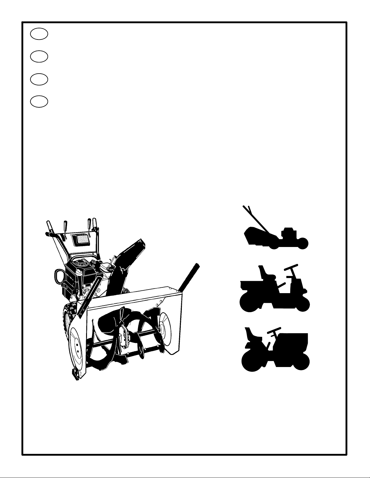
Instruction Book Snow Thrower
Model 627856x61
F
D
I
Manuel de l’utilisateur Chasse-neige
modèle 627856x61
Betriebsanleitung Schneefräse
Modell 627856x61
Istruzioni per l’uso Spazzaneve
Modello 627856x61
407027 8/23/06
Printed in U.S.A
Page 2
213
Page 3

Page 4
GENERAL INFORMATION
This instruction book is written for a person with some mechanical ability.
Like most service books, not all the steps are described. Steps on how to
loosen or tighten fasteners are steps anyone can follow with some
mechanical ability. Read and follow these instructions before you use the
unit.
Know your product: If you understand the unit and how the unit
operates, you will get the best performance. As you read this manual,
compare the illustrations to the unit. Learn the location and the function of
the controls. To help prevent an accident, follow the operating instructions
and the safety rules. Keep this manual for future reference.
IMPORTANT: Many units are not assembled and are sold in cartons. It is
the responsibility of the owner to make sure the assembly instructions in
this manual are exactly followed. Other units are purchased in an
assembled condition. On assembled units, it is the responsibility of the
owner to make sure the unit is correctly assembled. The owner must
carefully check the unit according to the instructions in this manual before
it is first used.
GB
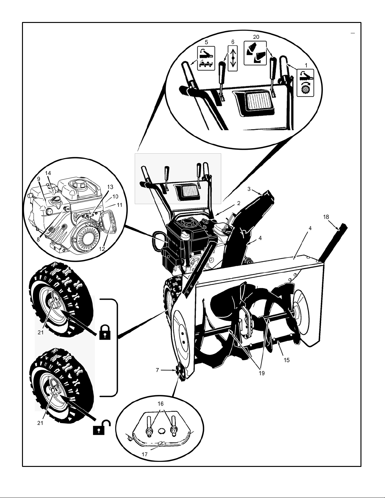
Controls & Equipment Features (see Figure 1)
Crank Assembly (2) -- Changes the direction of the discharge chute.
Chute Deflector (3) -- Changes the distance the snow is thrown.
Discharge Chute (4) -- Changes the direction the snow is thrown.
Auger Drive Lever (5) -- Starts and stops the auger (snow gathering and
throwing) which also propels the snowthrower..
Engine Features
Stop Switch (8) -- If equipped, move to the ON position to start the
engine.
Primer Button (9) -- Injects fuel directly into the carburetor for fast starts
in cold weather.
Recoil Starter Handle (12) -- Use to manually start the engine.
Choke Control (14) -- Use to start a cold engine.
Declared vibration emission values in accordance with Directive 98/37/EC.
Vibration Emission according to EN 1033;1996: 5,9
Values determined at the handle when the machine was operated stationary on a
concrete surface at 3700 min--1.
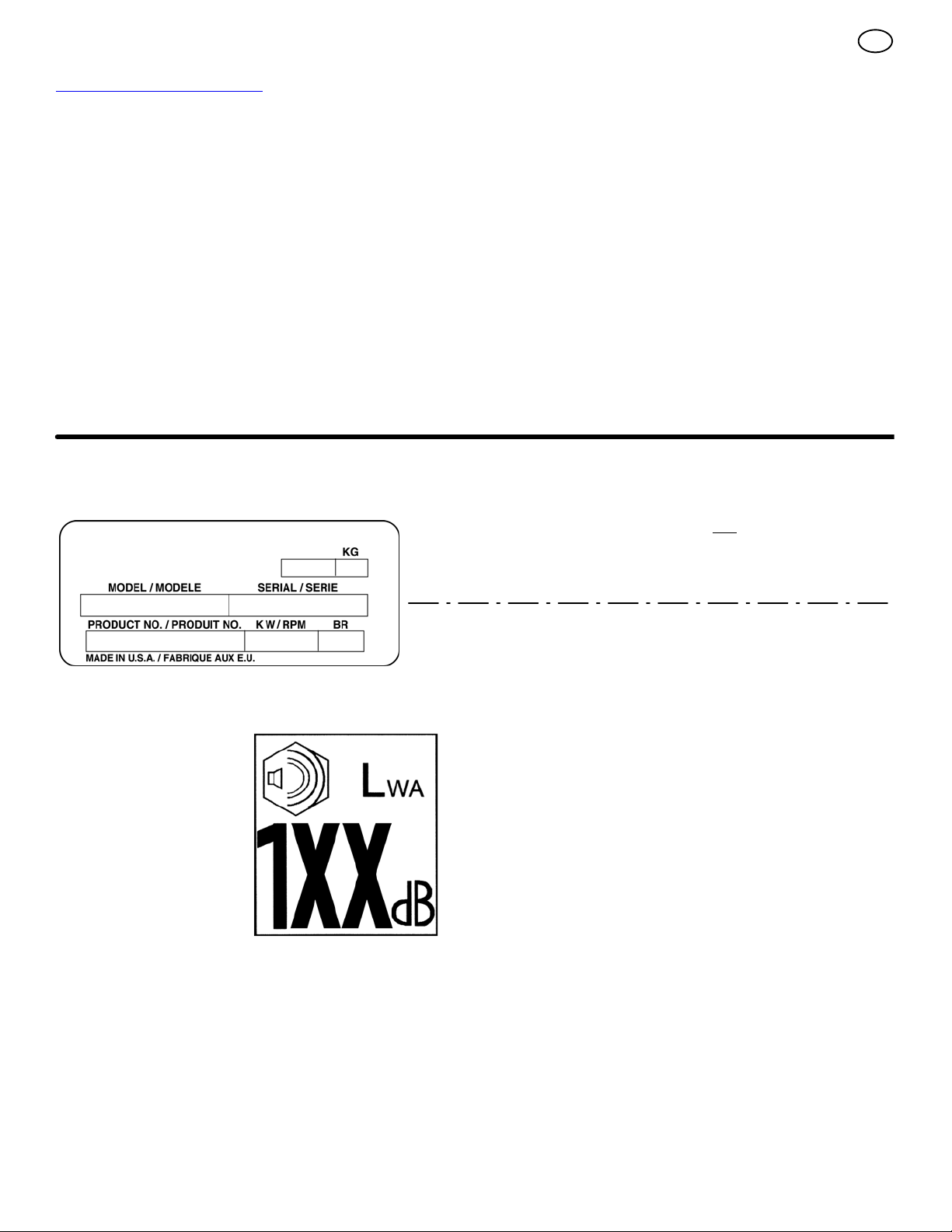
Declared airborne noise emissions of Lw
2000/14/EC, Annex V.
Sound Pressure Level at operator position 87 dB.
Values determined at ear according to the specifications of EN ISO 11201.
Declared airborne sound
power level of 104 dB(A) is in
accordance with Directive
2000/14/EC.
A 104 dB is in accordance with Directive
m/s2.
4
Page 5
This manual contains safety information to make you
aware of the hazards and risks associated with snow
throwers, and how to avoid them. The snow thrower is designed and
intended for removal of snow, and should not be used for any other
purpose. It is important that you read and understand these
instructions, and anyone operating the equipment read and understand
these instructions.
GB
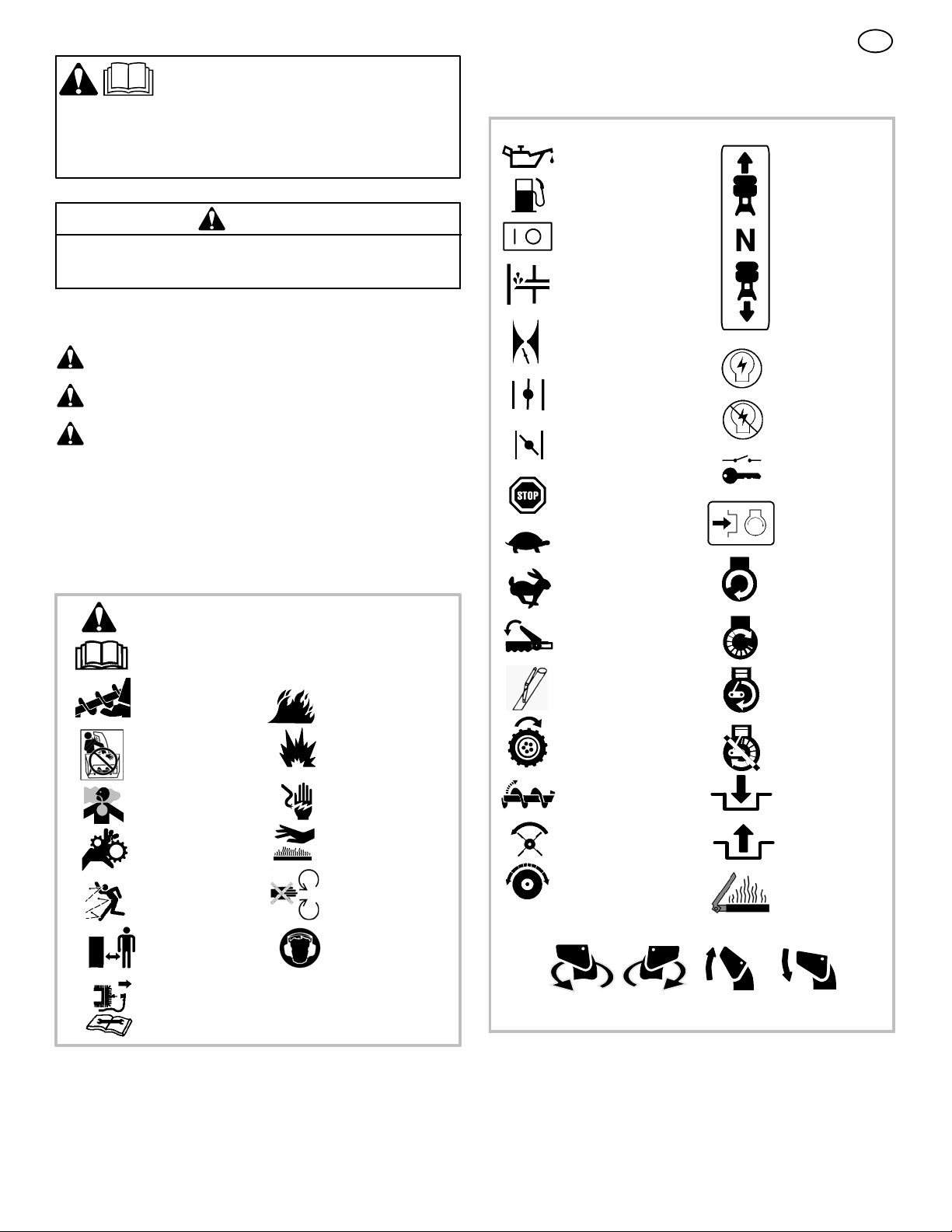
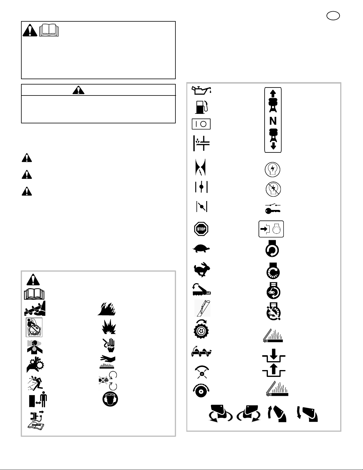
Operating Symbols and their meanings
These symbols are used on your equipment and defined in your operating
manual. It is important that you review and understand the meanings.
Failure to understand the symbols might result in harm to you.
Oil
WARNING
The engine exhaust from this product c ontains chemicals known to the
State of California to cause cancer, birth defects, or other reproductive
harm.
A signal word (DANGER, WARNING, or CAUTION) is used with the alert
symbol to indicate the likelihood and the potential severity of injury. In
addition, a hazard symbol may be used to represent the type of hazard.
DANGER indicates a hazard which, if not avoided, will result in
death or serious injury.
WARNING indicates a hazard which, if not avoided, could result
in death or serious injury.
CAUTION indicates a hazard which, if not avoided, might result
in minor or moderate injury.
CAUTION, when used without the alert symbol, indicates a
situation that could result in damage to the equipment.
Hazard Symbols and the meanings
These symbols are used on your equipment and defined in your operating
manual. Review and understand the meanings. The use of one of these
symbols c ombined with a signal word will alert you to potential hazards
and how to avoid them.
Safety Alert -- Identifies safety information about
hazards that can result in personal injury.
Operator’s Manual -- Read and understand before
performing any activity or running equipment.
Fuel
On Off
Primer bulb
Throttle
Choke off
Choke on
Stop
Slow
Fast
Engage
Foward
Neutral
Reverse
Ignition On
Ignition Off
Ignition Key
Push to engage
electric start
Electric
Start
Engine
Start
Rotating auger
Rotating impeller
Toxic fumes
Rotating gears
Thrown objects
Keep a safe distance
from the equipment.
Shut off engine and remove spark plug connector
before performing maintenance or repair work.
Fire
Explosion
Shock
Hot Surface
Never reach into
rotating parts.
Recommended ear
protection for extended
use.
Engage
Traction
Auger Collector
Auger Clutch
Drive Clutch
Discharge Chute
LEFT UP
RIGHT
Chute Deflector
Engine Run
Engine Off
Engage
Disengage
Heated Grips
DOWN
5
Page 6

WARNING: This machine is capable ofto amputating hands and feet and throwing objects. Read these safety rules
and follow them closely. Failure to obey these rules could result in loss of control of unit, severe personal injury or
death to you, or bystanders, or damage to property o r equipment. The triangle in text signifies important cautions or warnings which must be followed.
Safe Operation Practices for Snowthrowers
IMPORTANT: Safety standards require operator presence controls to
minimize the risk of injury. Your snowthrower is equipped with such controls. Do not attempt to defeat the function of the operator presence control under any circumstances.
Training
1. Read, understand, and follow all instructions on the machine and in the
manuals before operating this unit. Be thoroughly familiar with the controls and the proper use of the equipment. Know how to stop the unit
and disengage the controls quickly.
2. Never allow children to operate the equipment. Never allow adults to
operate the equipment without proper instruction.
3. Keep the area of operation clear of all persons, particularly small
children and pets.
4. Exercise caution to avoid slipping or falling especially when operating in
reverse.
Preparation
1. Thoroughly inspect the area where the equipment is to be used and
remove all doormats, sleds, boards, wires, and other foreign objects.
2. Disengage all clutches and shift into neutral before starting the engine
(motor).
3. Do not operate the equipment without wearing adequate winter outer
garments. Wear footwear that will improve footing on slippery surfaces.
Avoid loose fitting clothing that can get caught in moving parts.
4. Handle fuel with care; it is highly flammable.
a. Use an approved fuel container.
b. Never add fuel to a running engine or hot engine.
c. Fill fuel tank outdoors with extreme care. Never fill fuel tank indoors.
Replace fuel cap securely and wipe up spilled fuel.
d. Never fill containers inside a vehicle or on a truck or trailer bed with
a plastic liner. Always place containers on the ground, away from
your vehicle, before filling.
e. When practical, remove gas--powered equipment from the truck or
trailer and refuel it on the ground. If this is not possible, then refuel
such on a trailer with a portable container, rather than from a gasoline dispenser nozzle.
f. Keep nozzle in contact with the rim of the fuel tank or container
opening at all times, until refueling is complete. Do not use a nozzle
lock--open device.
g. Replace gasoline cap securely and wipe up spilled fuel.
h. If fuel is spilled on clothing, change clothing immediately.
5. Use extension cords and receptacles as specified by the manufacturer for all units with electric drive motors or electric starting motors.
6. Adjust the collector housing height to clear gravel or crushed rock
surfaces.
7. Never attempt to make any adjustments while the engine (motor) is
running (except when specifically recommended by manufacturer).
8. Let engine (motor) and snowthrower adjust to outdoor temperatures
before starting to clear snow.
9. Always wear safety glasses or eye shields during operation or while
performing an adjustment or repair to protect eyes from foreign objects
that may be thrown from the machine.
GB
Operation
1. Do not put hands or feet near or under rotating parts. Keep clear of the
discharge opening at all times.
2. Exercise extreme caution when operating on or crossing gravel drives,
walks or roads. Stay alert for hidden hazards or traffic.
3. After striking a foreign object, stop the engine (motor), remove the wire
from the spark plug, disconnect the cord on electric motors, thoroughly
inspect snowthrower for any damage, and repair the damage before
restarting and operating the snowthrower.
4. If the unit should start to vibrate abnormally, stop the engine (motor)
and check immediately for the cause. Vibration is generally a warning
of trouble.
5. Stop the engine (motor) whenever you leave the operating position,
before unclogging the collector/impeller housing or discharge chute and
when making any repairs, adjustments, or inspections.
6. When cleaning, repairing, or inspecting, make certain the collector/impeller and all moving parts have stopped. Disconnect the spark plug
wire and keep the wire away from the spark plug to prevent accidental
starting.
7. Do not run the engine indoors, except when starting the engine and for
transporting the snowthrower in or out of the building. Open the outside
doors; exhaust fumes are dangerous (containing CARBON MONOXIDE, an ODORLESS and DEADLY GAS).
8. Exercise extreme caution when operating on slopes. Do not attempt to
clear steep slopes.
9. Never operate the snowthrower without proper guards, plates, or other
safety protective devices in place and working.
10. Never direct the discharge toward people or areas where property
damage can occur. Keep children and others away.
11. Do not overload the machine capacity by attempting to clear snow at
too fast a rate.
12. Never operate the machine at high transport speeds on slippery surfaces. Look behind and use care when operating in reverse.
13. Disengage power to the collector/impeller when snowthrower is transported or not in use.
14. Use only attachments and accessories approved by the manufacturer
of the snowthrower (such as cabs, tire chains, etc..).
15. Never operate the snowthrower without good visibility or light. Always
be sure of your footing and keep a firm hold on the handles. Walk,
never run.
16. Never touch a hot engine or muffler.
17. Never operate the snowthrower near glass enclosures, automobiles,
window wells, drop--offs, and the like without proper adjustment of the
snow discharge angle.
18. Never direct discharge at bystanders or allow anyone in front of the
unit.
19. Never leave a running unit unattended. Always disengage the auger
and traction controls, stop engine, and remove keys.
20. Do not operate the unit while under the influence of alcohol or drugs.
21. Keep in mind the operator is responsible for accidents occurring to
other people or property.
22. Data indicates that operators, age 60 years and above, are involved
in a large percentage of power equipment--related injuries. These
operators s hould evaluate their ability to operate the unit safely
enough to protect themselves and others from injury.
23. DO NOT wear long scarves or loose clothing that could become
entangled in moving parts.
24. Snow can hide obstacles. Make sure to remove all obstacles from
theareatobecleared.
6
Page 7

Children
Tragic accidents can occur if the operator is not alert to the presence of children. Children are often attracted to the unit and the operating activity. Never
assume that children will remain where you last saw them.
1. Keep children out of the area and under the watchful care of another
responsible adult.
2. Be alert and turn off if children enter the area.
3. Never allow children to operate the unit.
4. Use extra care when approaching blind corners, shrubs, trees, or
other objects that may obscure vision.
Clearing A Clogged Discharge Chute
Hand contact with the rotating impeller inside the discharge chute is the
most common cause of injury associated with snowthrowers. Never use
your hand to clean out the discharge chute.
To clear the chute:
1. SHUT OFF THE ENGINE.
2. Wait 10 seconds to be sure the impeller blades have stopped rotating.
3. Always use a clean out tool, not your hands.
Service, Maintenance And Storage
1. Check shear bolts and other bolts at frequent intervals for proper tightness to be sure the equipment is in safe working condition.
2. Never store the machine with fuel in the tank inside a building where
ignition sources are present such as hot water and space heaters, or
clothes dryers. Allow the engine to cool before storing in any enclosure.
3. Always refer to operator’s manual for important details if the snowthrower is to be stored for an extended period.
4. Maintain or replace safety and instruction labels as necessary.
5. Run the machine a few minutes after throwing snow to prevent freeze-up of the collector/impeller.
6. If fuel is spilled, do not attempt to start the engine but move the machine away from the area of spillage and avoid creating any source of
ignition until fuel vapors have dissipated.
GB
7. Always observe safe refueling and fuel handling practices when refueling the unit after transportation or storage.
8. Always follow the engine’s manual instructions for storage preparations
before storing the unit for both short and long term periods,
9. Always follow the engine manual instructions for proper start-up procedures when returning the unit to service.
10. Maintain or replace safety and instruction labels as necessary.
11. Keep nuts and bolts tight and keep equipment in good condition.
12. Never tamper with safety devices. Check their proper operation regularly and make necessary repairs if they are not functioning properly.
13. Components are subject to wear, damage, and deterioration. Frequently check components and replace with manufacturer’s recommended
parts, when necessary .
14. Check control operation frequently. Adjust and service as required.
15. Use only factory authorized replacement parts when making repairs.
16. Always comply with factory specifications on all settings and adjustments.
17. Only authorized service locations should be utilized for major service
and repair requirements.
18. Never attempt to make major repairs on this unit unless you have been
properly trained. Improper service procedures can result in hazardous
operation, equipment damage and voiding of manufacturer’s warranty.
19. Check shear bolts (pins) and other bolts at frequent intervals for proper
tightness to be sure the equipment is in safe working condition.
Emissions
1. Engine exhaust from this product contains chemicals known, in certain
quantities, to cause cancer, birth defects, or reproductive harm.
2. If available, look for the relevant Emissions Durability Period and Air
Index information on the engine emissions label.
Ignition System
1. This spark ignition system complies with Canadian ICES-002.
7
Page 8
ASSEMBLY
Read and follow the assembly and adjustment
instructions for your snow thrower. All fasteners
are in the parts bag. Do not discard any parts or
material until the unit is assembled.
WARNING: Before doing any
assembly or maintenance to the
snow thrower, remove the wire
from the spark plug.
NOTE: In this instruction book, left and right
describe the location of a part from the operator’s position behind the unit.
NOTE: Torque is measured in foot pounds
(metric N.m). This measurement describes
how tight a nut or bolt must be. The torque is
measured with a torque wrench.
NOTE: Fasteners and loose parts are shown
at full size in Figure 2 on page 56.
NOTE: Illustrations are located on page 2
and on pages 57 through 62.
Tools Required
1Knife
1 Pliers
2 1/2 inch open end wrenches
2 9/16 inch open end wrenches
2 3/4 inch open end wrenches
1 Measuring tape or ruler
1 Screwdriver
How To Remove The Snow Thrower
From The Carton
1. (Figure 3) The snow thrower is shown in the
shipping position.
2. Cut and discard the plastic ties that secure
the crank assembly and the speed control
rod assembly.
3. Cut down all four corners of the carton and
lay the side panels flat.
4. Locate all parts that are packed separately
and remove from the carton.
5. Remove and discard the packing material
from around the snow thrower.
6. (Figure 1) For shipping purposes, the height
adjust skids (7) are attached to the pallet.
Remove the screw (17) that secures each
height adjust skid (7) to the pallet.
7. Hold onto the lower handle and pull the snow
thrower off the pallet.
CAUTION: DO NOT back over cables.
8. Remove the packing material from the handle assembly.
9. Cut the ties that secure the clutch control
cables (1) to the lower handle (2). Move the
cables away from the motor frame.
How To Assemble The Handle And
Crank Assembly
1. (Figure 4) Loosen, but do not remove, the
fasteners (1) in the upper holes of the lower
handle.
2. Remove the fasteners and the crank assem-
bly eyebolt (11) from the lower holes of the
lower handle.
3. (Figure 1) Put the shift lever (6) into first
forward position.
4. (Figure 4) Raise the upper handle (2) to the
operating position.
NOTE: Make sure the cables are not
caught between the upper and lower handle.
5. Install the fasteners and the crank assembly
eyebolt (11) thatwereremovedinstep2.
DO NOT tighten until all fasteners are in
place.
6. (Figure 6) Attach the crank rod (15) to the
universal joint assembly (16) with the hair
pin (12).
7. (Figure 4) Tighten nut on eye bolt (11).
Make sure eye bolt (11) is properly aligned
and the crank (18) can freely rotate.
8. Tighten all handle fasteners.
How To Install The Knobs
NOTE: If knobs are already installed, go to
the next selection.
Remote Chute Knob (Figure 10)
1. Assemble remote chute knob (1) onto lever
(3) until snug against nut (2). On some mod-
els the remote chute knob (1) is attached.
2. Make sure lip (4) on the remote chute knob
(1) is pointed toward the engine.
3. Tighten the nut (2) against the bottom of the
remote chute knob (1).
Speed Select Knob
(Figure 10) Install the speed select knob (11)
to the speed select lever (1). On some models
the speed select knob (11) is attached.
How To Install The Speed Control Rod
1. (Figure 9) Attach the ball joint (6), located
on the bottom end of the speed control rod
(2), to the shift yoke assembly (7). The fasteners (8) are attached to the ball joint (6)
at the factory.
The length of the ball joint (6) and speed
control rod (2) have been pre--adjusted at
the factory. If an adjustment is required, loosen the nut (9). Remove the fasteners (8) to
disconnect the ball joint (6) from the shift
yoke assembly (7). To lengthen or shorten
the speed control rod (2), turn the adapter
(10) to obtain the correct length.
2. (Figure 10) Attach the handle (11) onto the
speed select lever (5). On some models the
handle (11) is attached. To lock in position,
tighten the hex jam nut (10) against the bottom of the handle (11).
3. Make sure the speed select lever (5) functions correctly. Move the speed select lever
(5) through all speeds.
How To Assemble The Chute Deflector
1. (Figure 7) Remove carriage bolt (1).
2. Raise the chute deflector (2) into operating
position (3).
3. Fasten chute deflector (2) to flange (4) with
carriage bolts (1). Make sure to install with
head of the carriage bolts (1) on the inside
of the flange (2).
4. Fasten with washers (5) and locknuts (6).
5. Tighten locknuts (6) securely.
NOTE: Make sure all carriage bolts in flange
are tight. DO NOT OVERTIGHTEN.
8
GB
Check The Cables
1. (Figure 8) Check the traction drive cable
(1) and the auger drive cable (2). If the bot-
tom of the cables have become disconnected, reinstall the cables.
2. (Figure 11) If the top of the cables (5) have
become disconnected from the drive levers
(6), attach the cables (5) to the “Z” fitting
(7).
How To Set The Skid Height (Figure 1)
The snow thrower is equipped with height adjustable skids (7) mounted on the outside of the
auger housing (4). To adjust the height of the
skids, see “How To Adjust The Height Of The
Skids” in the Maintenance section.
How To Set The Length Of The Cables
The cables were adjusted at the factory and no
adjustments s hould be necessary. However, after the handles are put in the operating position,
the cables can be too tight or too loose. If an
adjustment is necessary, see “How To Check
And Adjust The Cables” in the Service And Adjustment section.
How To Assemble The Drift Cutter
(if equipped)
Drift cutters are used to cut a path through snow
deeper than the auger housing.
1. (Figure 12) Loosen the fasteners (2) that
secure the drift cutters (1) to the auger
housing.
2. Raise the drift cutters (1) to the desired
height.
3. Tighten the fasteners (2).
How To Prepare The Engine
NOTE: The engine was shipped from the
factory filled with oil. Check the level of the
oil. Add oil as needed.
WARNING: Follow the engine
manufacturer’s instructions for the
type of fuel and oil to use. Always
use a safety fuel container. Do not smoke
when adding gasoline to the engine. When
inside an enclosure, do not fill with gasoline. Before you add fuel, stop the engine.
Let the engine cool for several minutes.
Check the oil. See the engine manufacturer’s
instructions for the type of fuel and oil to use.
Before you use the unit, read the information on
safety, operation, maintenance, and storage.
Important! Before You Start Operating
Check the fasteners. Make sure all fas-
U
teners are tight.
U On electric start models, the unit was
shipped with the starter cord plugged
into the engine. Before operating, unplug the starter cord from the engine.
Page 9
OPERATION
NOTE: Illustrations are located on page 2
and on pages 57 through 62.
CAUTION: Use only attachments and accessories approved by the manufacturer of the
snow thrower (such as tire chains, electric
start kits, etc.).
Know Your Snow Thrower (Figure 1)
Read this Instruction Book and safety rules before operation the snow thrower. Compare the
illustration with your snow thrower to familiarize
yourself with the location of various controls and
adjustments.
How To Control
The Discharge Of The Snow
WARNING: Never direct the discharge of snow toward bystanders.
WARNING: Always stop the engine
before unclogging the discharge
chute or the auger housing and be-
fore leaving the snow thrower.
1. (Figure 1) Turn the crank assembly (2) to
change the discharge direction of the snow.
2. Push the remote chute lever (20) forward to
discharge the snow high and far. Pull the re-
mote chute lever (20) back to discharge the
snow down.
How To Stop
The Snow Thrower (Figure 1)
1. To stop discharging snow, release the auger
drive lever (5).
2. To stop the wheels, release the traction
drive lever (1).
3. To stop the engine, push the stop switch
(13) to the OFF position..
CAUTION: To stop the engine, do not move
the choke control to CHOKE position. Backfire or engine damage can occur.
How To Go Forward or Backward
(Figure 1)
1. To change the ground speed, first release the
traction drive lever (1) and then move the
speed shift lever (6) to the desired speed.
2. Ground speed is determined by snow conditions. Select the speed by moving the speed
shift lever (6) into the appropriate notch on
the shift lever plate.
Speed 1, 2 Wet, Heavy
Speed 3 Light
Speed 4 Very Light
Speed 5, 6 Transport only
3. To go forward, engage the traction drive
lever (1). Maintain a firm hold on the handle
as the snow thrower starts to move forward.
Guide the snow thrower by moving the handle either left or right. Do not attempt to push
the snow thrower.
4. To go backward, release the tractor drive
lever (1).
5. Move the speed shift lever (6) into either
first or second reverse.
6. Engage the traction drive lever (1).
IMPORTANT: Do not move the speed shift
lever (6) while the traction drive lever (1) is
engaged.
How To Throw Snow (Figure 1)
1. Engage the auger drive lever (5).
2. To stop throwing snow, release the auger
drive lever (5).
WARNING: The operation of any
snow thrower can result in foreign
objects being thrown into the eyes,
which can result in severe eye damage.
Always wear safety glasses or eye shields
while operating the snow thrower. We recommend standard safety glasses or use a
wide vision safety mask over your glasses.
How To Use The Wheel Lockout Pin
(Figure 13)
1. The right hand wheel is secured to the axle
with a klick pin (1). This unit was shipped
with this klick pin (1) through the wheel hole
in the locked position (2).
2. For ease of maneuverability in light snow
conditions, change the klick pin (1) to an
unlocked position (3).
3. Disconnect the klick pin (1) from the wheel
locked position (2). Push the klick pin (1)
through the unlocked axle hole only. The unit
is now in the single wheel drive unlocked
position (3).
Before Starting The Engine
1. Before you service or start the engine, familiarize yourself with the snow thrower. Be
sure you understand the function and location of all controls.
2. Check the tension of the clutch cable before
starting the engine. See “How To Adjust The
Clutch Cable” in the Maintenance section of
this manual.
3. Make sure that all fasteners are tight.
4. Make sure the height adjust skids are properly adjusted. See “How To Adjust The Height
Of The Skids” in the Maintenance section of
this manual.
5. Check the air pressure in the tires. The correct air pressure is 14 PSI (1 BAR) to 17 PSI
(1.25 BAR). Do not exceed the maximum
amount of air pressure shown on the side of
the tire.
How To Stop The Engine (Figure 1)
1. Push the stop switch (13) to the OFF position.
2. Pull out the safety key (8).
CAUTION: To stop the engine, do not move
the choke control to CHOKE position. Backfire or engine damage can occur.
How To Start The Engine (Figure 1)
Models equipped with an Electric Starter
NOTE: An electric starter kit can be added to
recoil start engines. Electric starter kits are
available from your nearest authorized service center.
9
GB
WARNING: The starter is equipped
with a three--wire power cord and
plug and is designed to operate on
220 volt A.C. household current. The power
cord must be properly grounded at all times
to avoid the possibility of electrical shock
which can injure the operator. Carefully follow all instructions in the “How To Start The
Engine” section. Make sure that your house
wiring is a three--wire grounded system. If
you are not sure, ask a licensed electrician.
If your house wire system is not a
three--wire grounded system, do not use
this electric starter under any conditions. If
your system is grounded but a three--hole
grounded receptacle is not available to start
the engine, have a three--hole grounded receptacle installed by a licensed electrician.
To connect a 220 volt A.C. power cord, always connect the power cord to the switch
box (11) on the engine first. Then, plug the
other end into the three--hole grounded receptacle. When disconnecting the power
cord, always unplug the end from the
three--hole grounded receptacle first.
How To Start A Cold Engine (Figure 1)
1. Check the engine oil.
2. Fill the fuel tank with regular unleaded petrol.
See “How To Prepare The Engine”.
3. Make sure the traction drive lever (1) and
the auger drive lever (5) are in the disengaged (released) position.
4. Push the stop switch (13) to the ON position.
5. Push in the safety key (8).
6. Rotate the choke knob (14) to the CHOKE
position.
7. (Electric Start) Connect the power cord to
the starter motor located on the engine.
8. (Electric Start) Plug the other end of the
power cord into a three--hole, grounded 220
VOLT, A.C. receptacle. (See the WARNING
in this section).
9. Push the primer button (9). Every time you
push the primer button (9),waittwoseconds. For the number of times required to
push the primer button (9), see the engine
manufacturer’s instructions.
10.(Electric Start) Push on the electric start
button (10) until the engine starts. Do not
crank for more than 5 seconds at a time.
Wait one minute between starts to allow the
starter to cool.
11. (Recoil Start) Slowly pull the recoil starter
handle (12) until resistance is felt and then
pull rapidly to start the engine. Do not allow
the recoil starter handle (12) to snap back.
Slowly return the recoil starter handle (12).
12.If the engine does not start in 5 or 6 tries,
See the “Trouble Shooting Chart” Instructions.
13.1.Allow the engine to warm up for several
minutes. As the engine warms up, adjust the
choke knob (14) toward the RUN position.
Wait until the engine runs smoothly before
each choke adjustment.
14.(Electric Start) First disconnect the power
cord from the three--hole receptacle. Then,
disconnect the power cord from the starter
motor.
NOTE: In temperatures below 0°F, allow
the engine to warm up for several minutes
before blowing snow.
Page 10
WARNING: Never run the engine
indoors or in enclosed, poorly ven-
tilated areas. Engine exhaust contains carbon monoxide, an odorless and
deadly gas. Keep hands, feet, hair and
loose clothing away from any moving parts
located on the engine or the snow thrower.
The temperature of muffler and nearby
areas may exceed 150°F. Avoid these
areas.
How To Start A Warm Engine (Figure 1)
If an engine has been running and is still warm,
leave the choke control (14) in the off position
and do not push the primer button (9).Ifthe
engine fails to start, follow the instructions “How
To Start A Cold Engine”.
NOTE: Do not use the primer button (9) to
start a warm engine.
How ToStart An Engine With A Frozen Electric
Starter (Figure 1)
If the electric starter is frozen and will not turn
the engine, follow the instructions below.
1. Pull as much starter rope as possible out of
the starter.
2. Release the starter handle and let it snap
back against the starter. Repeat until the engine starts.
Warm engines will cause condensation in cold
weather. To prevent possible freeze--up of recoil
starter and engine controls, proceed as follows
after each snow removal job.
1. Run the snow thrower a few minutes after
throwing snow to prevent freeze--up of the
auger/impeller.
2. With engine off, allow engine to cool for several minutes.
3. Pull starter rope very slowly until resistance
is felt, then stop. Allow the starter rope to recoil. Repeat three times.
4. With the engine not running, wipe all snow
and moisture from the carburetor cover in
area of controls and levers. Also, move the
choke control and starter handle several
times.
How To Remove Snow or Debris From
The Auger Housing
WARNING: Do not attempt to remove snow or debris that may be-
come lodged in auger housing with
your hands. Use the clean--out tool or a pry
bar to remove snow or debris.
(Figure 5) On some models, a clean--out tool is
attached to the top of the auger housing. Use
the clean--out tool to remove snow from the auger housing.
1. (Figure 1) Release the auger drive lever
(5).
2. Move the throttle control (13) to the stop
position.
3. Pull out the safety key (8).
4. Disconnect the spark plug wire.
5. Do not place your hands in the auger hous-
ing (4) or the discharge chute (3).
6. (Figure 5) Use the clean--out tool (1) or a
pry bar to remove any snow or debris.
GB
Snow Throwing Tips
1. For maximum snow thrower efficiency in removing snow, adjust ground speed. Go
slower in deep, freezing or wet snow. If the
wheels s lips, reduce forward speed.
2. Most efficient snow throwing is accomplished
when the snow is removed immediately after
if falls.
CAUTION: Do not overload the machine
capacity by attempting to clear snow at
too fast a rate.
3. For complete snow removal, slightly overlap
each previous path.
4. Whenever possible, discharge the snow
down wind.
5. For normal usage, set the skids so that the
scraper bar is 1/8” above the skids. For extremely hard--packed snow surfaces, adjust
the skids upward so that the scraper bar
touches the ground.
6. Rocks and gravel must not be picked up and
thrown by the machine. On gravel or crushed
rock surfaces, set the skids at 1--1/4 inch below the scraper bar. See “How To Adjust The
Height Of The Skids” in the Maintenance
section.
7. After each snow throwing job, allow the engine to idle for a few minutes. The snow and
accumulated ice will melt off the engine.
8. Clean the snow thrower after each use.
9. Remove ice, snow and debris from the entire
snow thrower. Flush with water to remove all
salt or other chemicals. Wipe snow thrower
dry.
10
Page 11
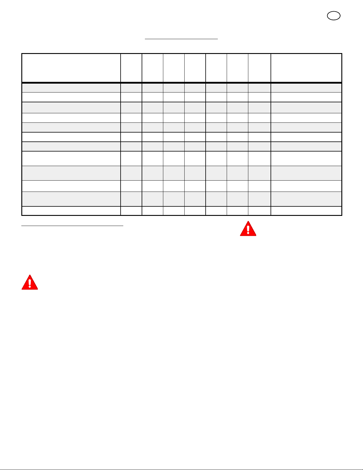
CUSTOMER RESPONSIBILITIES
SERVICE RECORDS
Fill in dates as you
complete regular
service.
Check Engine Oil Level
Change Engine Oil
Check And Tighten All Screws and Nuts
Check Spark Plug
Adjust Drive Belt
Check Fuel
Drain Fuel
Check Auger Clutch Cable Adjustment
(See Cable Adjustment)
Check Traction Clutch Cable Adjustment
(See Cable Adjustment)
MAINTENANCE CHART
Before
Each
Use
First
2
Hours
Every
5
Hours
Every
10
Hours
Every
25
Hours
√ √ √
√ √
√ √
√ √
√ √ √
√
√ √
√ √
Each
Season
Before
Storage
√
GB
SERVICE DATES
Lubricate All Pivot Points
Lubricate Auger Shaft
(See Shear Bolt Replacement)
Lubricate Drive Chains and Sprockets
MAINTENANCE
NOTE: Illustrations are located on page 2
and on pages 57 through 62.
Use the following maintenance section to keep
your unit in good operating condition. All the
maintenance information for the engine is in the
engine manufacturer’s instructions. Before you
start the engine, read this book.
WARNING: Before you make an inspection, adjustment (except
carburettor), or repair, disconnect
thewirefromthesparkplug.
General Recommendations
The warranty on this snow thrower does not cover items that have been subjected to operator
abuse or negligence. To receive full value from
the warranty, the operator must maintain the
snow thrower as instructed in this manual.
Some adjustments must be made periodically to
properly maintain the snow thrower.
After Each Use
G Check for any loose or damaged parts.
G Tighten any loose fasteners.
G Check and maintain the auger.
G Check c ontrols to make sure they are
functioning properly.
G If any parts are worn or damaged, replace
immediately.
G Check all safety and instruction decals and
labels. Replace any decals or labels that are
missing or cannot be clearly read.
√
√ √
√ √
All adjustments in the Maintenance section of
this manual should be checked at least once
each season.
As Required
The following adjustment should be preformed
more than once each season.
1. Adjust the auger drive belt after the first 2 to
4 hours, again at mid--season, and twice
each season thereafter. See “How To Adjust
The Auger Drive Belt” in the Maintenance
section.
Lubrication
Every10Hours(Figure 14)
1. Lubricate the Zerk fittings (1)everyten
hours with a grease gun.
2. Each time a shear bolt is replaced, the auger
shaft must also be greased.
3. Lubricate all pivot points.
Every25Hours
Chute Rotation Gear
(Figure 6) Lubricate the chute rotation gear (1)
with automotive type oil.
Chains
1. (Figure 1) Move the speed shift lever (6) to
first gear.
2. Remove the gas from the gas tank. Stand
the snow thrower up on the front end of the
auger housing (4).
11
√
WARNING: Drain the gasoline outdoors, away from fire or flame.
3. (Figure 22) Loosen the bolts (3) on each
side of the bottom panel (2).
4. Remove the bottom panel (2).
5. (Figure 15) Lubricate the chains (5) with a
chain type lubricant.
6. Wipe the hexshaft and sprockets (6) with
5W30 motor oil.
NOTE: If grease or oil come in contact
withthediscdriveplate(1)orthefriction
wheel (3), damage can result. Clean off
any oil or grease with a alcohol base solvent.
7. (Figure 22) Install the bottom panel (2).
8. Tighten the bolts (3) on each side of the bot-
tom panel (2).
Items Not To Lubricate (Figure 15)
1. Do not lubricate the hex shaft and sprockets (6). All bearings and bushings are life-
time lubricated. For storage, put a slight
amount of 5W--30 motor oil on a cloth and
wipe the hex shaft and sprockets (6) to
prevent rust.
2. If grease or oil comes in contact with the
disc drive plate (1) or the friction wheel
(3),thefriction wheel (3) can be damaged.
Make sure to thoroughly clean the disc drive
plate (1) and the friction wheel (3).
CAUTION: Any greasing or oiling of the
above components can cause contamination of the friction wheel (3). If the disc
drive plate (1) or the friction wheel (3) become contaminated with grease or oil,
damage to the friction wheel will result.
Page 12
3. The auger gear case is lubricated at the factory and does not require additional lubrication. If for some reason the lubricant leaks
out, have the auger gear case checked by a
factory authorized service center.
How To Adjust The Height Of The Skids
(Figure 1)
This snow thrower is equipped with two height
adjustable skids (7). These skids elevate the
front of the snow thrower. For normal hard surfaces, such as a paved driveway or walk, adjust
the skids as follows.
1. Put the snow thrower on a level surface.
2. Make sure both tires are equally inflated.
The correct air pressure is 14 PSI (1 BAR) to
17 PSI (1.25 BAR). Do not exceed the maximum amount of air pressure shown on the
side of the tire.
3. Put the extra shear bolts (found in the parts
bag) under each end of the scraper bar (15)
next to the adjustable skids (7).
4. Loosen the mounting nuts (16) that hold the
adjustable skids (7). To bring the front of the
snow thrower down, raise each adjustable
skids (7) . Tighten the mounting nuts (16).
NOTE: For rocky or uneven surfaces, raise
the front of the snow thrower by moving the
adjustable skids (7) down.
WARNING: Be certain to maintain
proper ground clearance for the
area to be cleared. Objects such
as gravel, rocks or other debris, if struck
by the impeller, can be thrown with sufficient force to cause personal injury, property damage or damage to the snow thrower.
How To Adjust
The Scraper Bar (Figure 1)
After considerable use, the scraper bar (15) will
become worn. The scraper bar (15),inconjunction with the skids, must be adjusted to allow
1/8 inch clearance between the scraper bar
(15) and the sidewalk or area to be cleared.
1. Put the snow thrower on a level surface.
2. Make sure both tires are equally inflated.
The correct air pressure is 14 PSI (1 BAR) to
17 PSI (1.25 BAR). Do not exceed the maximum amount of air pressure shown on the
side of the tire.
3. Loosen the carriage bolts and nuts that hold
the scraper bar (15) to the auger housing
(4).
4. Adjust the scraper bar (15) to allow 1/8 inch
clearance between the scraper bar (15) and
the sidewalk or area to be cleared.
5. Tighten the carriage bolts and nuts. Make
sure that the scraper bar (15) is parallel with
the sidewalk or area to be cleared.
6. To extended the life of the scraper bar (15),
remove and reverse the mounting of the
scraper bar (15).
How To Check And Adjust The Cables
The traction drive cable and the auger drive
cable are adjusted at the factory. During normal
use, a cable can become stretched and must be
checked and adjusted as follows.
How To Check The Cables (Figure 16)
1. To check for correct adjustment, disconnect
the “Z” fitting (1) from the drive lever (2).
2. Move the drive lever (2) forward until the
drive lever (2) is contacting the plastic
bumper (3).
3. The control cable is correctly adjusted if the
center of the “Z” fitting (1) is aligned (4)
withtheholeinthedrive lever (2) and there
in no droop in the cable.
How To Adjust The Auger Drive Cable
1. Remove the gas from the gas tank. Stand
the snow thrower up on the front end of the
auger housing.
WARNING: Drain the gasoline outdoors, away from fire or flame.
2. (Figure 16) Disconnect the “Z” fitting (1)
from the drive lever (2).
3. (Figure 17) Pull the spring cover up to expose the spring (5). Push the cable (6)
through the spring (5) to expose the square
end (7) on the cable (6).
4. Hold the square end (7) with pliers and adjust the locknut (8) in or out until the excess
slack is removed.
5. Pull the cable (6) back through the spring
(5).
6. (Figure 16) Connect the “Z” fitting (1) to the
drive lever (2).
NOTE: When the auger drive belt is adjusted
or replaced, check and adjust the cable.
How To Adjust The Traction Drive Cable
1. Remove the gas from the gas tank. Stand
the snow thrower up on the front end of the
auger housing.
WARNING: Drain the gasoline outdoors, away from fire or flame.
2. (Figure 22) Loosen the bolts (3) on each
side of the bottom panel (2).
3. Remove the bottom panel (2).
4. (Figure 16) Disconnect the “Z” fitting (1)
from the traction drive lever (2).
5. (Figure 27) Slide the cable boot (3) off the
cable adjustment bracket (4).
6. Push the bottom of the traction control
cable (5) through the cable adjustment
bracket (4) until the “Z” hook (6) canbere-
moved.
7. Remove the “Z” hook (6) from the cable
adjustment bracket (4). Move the “Z” hook
(6) down to the next adjustment hole.
8. Pull the traction control cable (5) up
through the cable adjustment bracket (4).
9. Put the cable boot (3) over the cable ad-
justment bracket (4).
10.(Figure 16) Install the “Z” fitting (1) to the
traction drive lever (2).
11. (Figure 15) To check the adjustment, depress the drive lever and check the length
“A” of the drive spring (7). In correct adjustment, the length “A” of the drive spring (7)
is as follows:
minimum 3 inches (76 mm.)
maximum 3-3/8 inches (85 mm.).
12.(Figure 22) Install the bottom panel (2).
13.Tighten the bolts (3) on each side of the bot-
tom panel (2).
12
GB
How To Adjust The Belts
The belts will stretch during normal use. If you
need to adjust the belts due to wear or stretch,
proceed as follows.
How To Adjust The Auger Drive Belt
If the snow thrower will not discharge snow,
check the adjustment of the auger drive cable.
See “How To Check And Adjust The Cables” in
the Maintenance section. If the adjustment is
correct, then check the condition of the auger
drive belt. If the auger drive belt is damaged,
replace the auger drive belt. See “How To Replace The Belts” in the Maintenance section. If
the auger drive belt is loose, adjust as follows.
1. Disconnect the spark plug wire.
2. (Figure 18) Remove screw (2) from belt
cover (1). Remove the belt cover (1).
3. (Figure 19) Loosen the nut (2) on the idler
pulley (3) Move the idler pulley (3) 1/8 inch
toward the auger drive belt (4).
4. Tighten the nut (2).
5. (Figure 21) Depress the auger drive lever.
Check the tension on the auger drive belt
(4). In correct adjustment, the auger drive
belt (4) will deflect 1/2 inch (5) with moder-
ate pressure. If the adjustment is not correct,
repeat the adjustment.
6. (Figure 18) Install the belt cover (1). Tighten
screw (2).
7. Check the adjustment of the auger drive
cable. See “How To Check And Adjust The
Cables” in the Maintenance section.
8. Attach the spark plug wire.
Traction Drive Belt
The traction drive belt has constant spring pressure and does not require an adjustment. If the
traction drive belt is slipping, replace the belt.
See “How To Replace The Belts” in the Maintenance section.
How To Replace The Belts
The drive belts are of special construction and
must be replaced with original factory replacement belts available from your nearest authorized service center.
Some steps require the assistance of a second
person.
How To Remove the Auger Drive Belt
If the auger drive belt is damaged, the snow
thrower will not discharge snow. Replace the
damaged belt as follows.
1. Disconnect the spark plug wire.
2. (Figure 22) Loosen the bolts (3) on each
side of the bottom panel (2).
3. Remove the bottom panel (2).
4. (Figure 18) Remove screw (2) from belt
cover (1). Remove the belt cover (1).
5. (Figure 19) Loosen the belt guide (9). Pull
the belt guide (9) away from the auger
drive pulley (10).
6. Pull the idler pulley (3) away from the auger
drive belt (4) and slip the auger drive belt
(4) offoftheidler pulley (3).
7. Remove the auger drive belt (4) from the
engine pulley (11). To r e m ove th e auger
drive belt (4), the engine pulley (11) may
have to be partially rotated.
Page 13
8. (Figure 20) Remove the top four bolts (21)
that hold together the auger housing (22)
and the motor box (23). Loosen the bottom
two bolts (24). The auger housing (22) and
the motor box (23) can now be split apart for
removal of the belt.
9. (Figure 19) Remove the old auger drive
belt (4) from the auger drive pulley (10).
Replace the auger drive belt (4) with an
original factory replacement belt available
from an authorized service center.
10.Install the new auger drive belt (4) onto the
auger drive pulley (10).
11.Assemble the auger housing (22) to the
motor box (23) with the four bolts (21) that
wereremovedinstep8.Tightenthebottom
two bolts (24).
12.Install the auger drive belt (4) onto the en-
gine pulley (11).
13.Slip the auger drive belt (4) under the idler
pulley (3).
14.Adjust the auger drive belt (4). See “How To
Adjust The Auger Drive Belt” in the Maintenance section.
15.Adjust the belt guide (9). See “How To Adjust The Belt Guide” in the Maintenance section.
16.(Figure 18) Install the belt cover (1). Tighten
screw (2).
17.Check the adjustment of the cables. See
“How To Check And Adjust The Cables” in
the Maintenance section.
18.Connect the spark plug wire.
How To Remove the Traction Drive Belt
If the snow thrower will not move forward, check
the traction drive belt for wear or damage. If the
traction drive belt is worn or damaged, replace
the belt as follows.
1. Disconnect the spark plug wire.
2. Remove the auger drive belt. See “How To
Remove The Auger Drive Belt” in the Maintenance section.
3. (Figure 19) Remove the e--ring (17) from
one end of the swing plate axle rod (18).
Remove the swing plate axle rod (18) to
allow the the swing plate to pivot forward.
4. Remove the traction drive spring (16).
5. Remove the old traction drive belt (13) from
the traction drive pulley (14) and from the
engine pulley (15). Replace the traction
drive belt (13) with an original factory re-
placement belt available from an authorized
service center.
6. Install the new traction drive belt (13) onto
the traction drive pulley (14) and onto en-
gine pulley (15).
7. Make sure the traction drive idler pulley
(12) is properly aligned with the traction
drive belt (13).
8. Attach the traction drive spring (16).
9. Install the swing plate axle rod (18) and secure with the e--ring (17) removed earlier.
10.(Figure 30) The bottom of the swing plate
(20) must be positioned between the alignment tabs (19). Make sure the swing plate
(20) is properly secured.
NOTE: If the drive will not engage after
the traction drive belt has been replaced,
then check to make sure that the swing
plate is positioned between the alignment
tabs (19).
11. (Figure 19) Install and adjust the auger
drive belt (4). See “How To Remove The
Auger Drive Belt” in the Maintenance section.
12.Adjust the belt guide (9). See “How To Adjust The Belt Guide” in the Maintenance section.
13.(Figure 22) Install the bottom panel (2).
14.Tighten the bolts (3) on each side of the bot-
tom panel (2).
15.(Figure 18) Install the belt cover (1). Tighten
screw (2).
16.Check the adjustment of the cables. See
“How To Check And Adjust The Cables” in
the Maintenance section.
17.Connect the spark plug wire.
How To Adjust The Belt Guide
1. Disconnect spark plug wire.
2. (Figure 18) Remove screw (2). Remove the
belt cover (1).
3. (Figure 1) Engage the auger drive lever (5).
4. (Figure 23) Measure the distance between
the belt guide (2) and auger drive belt (3).
The correct distance (4) is 1/8 inch (3.175
mm).
5. If an adjustment is necessary, loosen the
mounting bolt for the belt guide (2).Move
the belt guide (2) to the correct position
(4). Tighten the mounting bolt for the belt
guide (2).
6. (Figure 18) Install the belt cover (1). Tighten
screw (2).
7. Connect the spark plug wire.
How To Adjust Or Replace The Friction
Wheel
How To Check The Friction Wheel
If the snow thrower will not move forward, check
thetractiondrivebelt,thetractiondrivecableor
the friction wheel. If the friction wheel is worn or
damaged, it must be replaced. See “How To
Replace the Friction Wheel” in this section. If the
friction wheel is not worn or damaged, check as
follows.
1. (Figure 1) Remove the gas from the gas
tank. Stand the snow thrower up on the front
end of the auger housing (4).
WARNING: Drain the gasoline outdoors, away from fire or flame.
2. Disconnect the spark plug wire.
3. (Figure 22) Loosen the bolts (3) on each
side of the bottom panel (2).
4. Remove the bottom panel (2).
5. (Figure 1) Position the shift speed lever (6)
in the lowest forward speed.
6. (Figure 24) Note the position of the friction
wheel (4). The correct distance “A” from the
right side of the friction wheel (4) to the outside of the motorbox is as follows:
Tire Size Distance “A”
12 and 13 inch 4-1/8” (10.5 cm.)
16 inch 4-5/16” (10.95 cm.)
If the friction wheel (4) is not in the correct
position, adjust as follows.
How To Adjust The Friction Wheel
1. (Figure 1) Position the shift speed lever (6)
in the lowest forward speed.
13
GB
2. (Figure 9) Loosen hex jam nut (9) on speed
select rod (2). Remove ball joint (6) from
shifter rod (7).
3. (Figure 24) Move the friction wheel (4) to
the correct position.
4. (Figure 9) Turn the adaptor (10) until the
ball joint (6) is aligned with the mounting
hole in the shifter rod (7). When aligned,
attach the ball joint (6) to the shifter rod (7).
5. (Figure 22) Install the bottom panel (2).
6. Tighten the bolts (3) on each side of the bot-
tom panel (2).
How To Replace The Friction Wheel
If the friction wheel is worn or damaged, the
snow thrower will not move forward. The friction
wheel must be replaced as follows.
1. (Figure 1) Remove the gas from the gas
tank. Stand the snow thrower up on the front
end of the auger housing (4).
WARNING: Drain the gasoline outdoors, away from fire or flame.
2. Disconnect the spark plug wire.
3. (Figure 28) Remove the fasteners that secure the left wheel (10). Remove the left
wheel (10) from the axle (11).
4. Loosen the bolts (3) on each side of the bot-
tom panel (2).
5. Remove the bottom panel (2).
6. (Figure 29) Remove the fasteners that secure the drive sprocket (12) to the axle (11).
7. Remove the right wheel, axle (11), and drive
sprocket (12).
8. (Figure 30) Remove the four bolts (16) that
hold the bearings (7) on each side of the
hex shaft (8).
9. (Figure 31) Remove the hex shaft (8) and
bearings (7).
NOTE: Take special note of the position of
the washers (17) .
10.(Figure 26) Remove the three fasteners (4)
that hold the friction wheel (5) to the hub
(6).
11. (Figure 26) Remove the friction wheel (5)
from the hub (6). Slip the friction wheel (5)
off the hex shaft (8).
12.Assemble the new friction wheel (5) onto
hub (6) with the fasteners removed earlier.
13.(Figure 31) Install the hex shaft (8) and
bearings (7) with the four bolts removed earlier.
Make sure the washers (17) are properly
installed in the original position. Also,
make sure the two washers (13) are properly aligned with the actuator arms (14).
14.Make sure the hex shaft (8) turns freely.
15.(Figure 29) Install the right wheel, axle (11),
and drive sprocket (12) with the fasteners
removed earlier. Install the chain (15) onto
drive sprocket (12).
the
16.Check the adjustment of the friction wheel.
See “How To Adjust The Friction Wheel” in
this section.
17.Make sure the friction wheel and the disc
driveplatearefreefromgreaseoroil.
18.(Figure 22) Install the bottom panel (2).
19.Tighten the bolts (3) on each side of the bot-
tom panel (2).
20.Install the left wheel (10) to the axle (11)
with the fasteners removed earlier.
21.Connect the spark plug wire.
Page 14
How To Replace the Auger Shear Bolt
The augers are secured to the auger shaft with
special s hear bolts. These shear bolts are designed to break and protect the machine if an
object becomes lodged in the auger housing.
Do not use a harder bolt as the protection provided by the shear bolt will be lost.
WARNING: For safety and to protect the machine, use only original
equipment shear bolts.
To replace a broken shear bolt, proceed as follows. Extra shear bolts were provided in the assembly parts bag.
1. (Figure 1) Move the stop switch (13) to the
stop position. Disengage all controls.
2. Disconnect the spark plug wire. Make sure
all moving parts have stopped.
3. (Figure 14) Lubricate the auger shaft Zerk
fitting (1), if equipped, with a grease gun.
4. (Figure 25) Align the hole in the auger with
the hole in the auger shaft. Install the new
shear bolt (2), spacer (3), and locknut (4).
5. Connect the spark plug wire.
How To Prepare The Snow Thrower For
Storage
WARNING: Do not remove gasoline
while inside a building, near a fire,
or while you smoke. Gasoline
fumes can cause an explosion or a fire.
If the snow thrower is to be stored for an extended period, refer to the engine manufacturer’s operating manual (included with some
models) for important maintenance or storage
details.
1. Drain the fuel tank.
2. Let the engine run until it is out of gasoline.
3. Never store the snow thrower with fuel in the
tank inside a building where ignition sources
are present such as hot water and space
heaters, clothes dryers, and the like. Allow
the engine (motor) to cool before storing in
any enclosure.
4. Drain the oil from the warm engine. Fill the
engine crankcase with new oil.
5. Remove the spark plug from the cylinder.
Pour one ounce of oil into the cylinder. Slowly pull the recoil--start grip so that the oil will
protect the cylinder. Install a new spark plug
in the cylinder.
6. Remove the spark plug and pour about 15 ml
(1/2 oz) of engine oil into the cylinder. Replace the spark plug and crank slowly to distribute the oil.
7. Thoroughly clean the snow thrower.
8. Lubricate all lubrication points. See the Maintenance section.
9. Be sure that all nuts, bolts and screws are
securely fastened. Inspect all visible moving
parts for damage, breakage and wear. Replace if necessary.
10.Cover the bare metal parts of the blower
housing, auger, and the impeller with spray
rust preventative lubricant.
11.Put the unit in a building that has good ventilation. Store in a clean and dry area, but
NOT near a stove, furnace or water heater
which uses a pilot light or any device that can
create a spark.
12.If the machine must be stored outdoors,
block up the snow thrower to be sure the entire machine is off the ground.
GB
13.Cover the snow thrower with a suitable protective cover that does not retain moisture.
Do not use plastic.
How To Order Replacement Parts
The replacement parts are shown either on the
back pages of this Instruction Book or in a
separate Parts List Book.
Use only manufacturer’s authorized or approved
replacement parts. The letter placed on the end
of the part number denotes the type of finish for
the part, C for chrome, Z for zinc, a PA for
purchased assembly. It is important that you
include this when ordering a part. Do not use
attachments or accessories not specifically
recommended for this unit. In order to obtain
proper replacement parts you must supply the
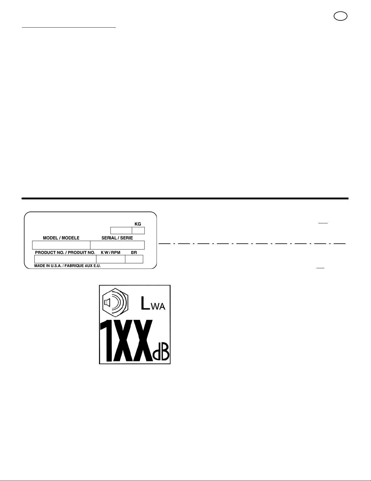
model number (see nameplate).
To obtain replacement parts, contact:
BRIGGS AND STRATTON CANADA
Factory Customer Service
1195 Coutneypark Drive East
Mississauga, Ont. L5T--1R1
1--800--661--6662
Collect telephone calls will not be accepted.
Replacement parts for the engine, transaxle, or
transmission, are available from the
manufacturer’s authorized service centre found
in the yellow pages of the telephone directory.
Also, see the individual engine or transmission
warranties to order replacement parts.
When ordering the following information is
required:
(1) The Model Number
(2) Serial Number
(3) Part Number
(4) Quantity
14
Page 15

TROUBLE SHOOTING CHART
TROUBLE CAUSE CORRECTION
Difficult starting Defective spark plug. Replace spark plug.
GB
Water or dirt i n fuel system. Use carburetor bowl drain to flush and refill with
Engine runs erratic Blocked fuel line, empty gas tank, or stale
Engine stalls Unit running on CHOKE. Set choke lever to RUN position.
Engine runs erratic;
Loss of power
Excessive vibration Loose parts: damaged impeller Stop engine immediately and disconnect spark
Unit fails to propel itself Drive belt loose or damaged. Replace drive belt.
Unit fails to discharge snow Auger drive belt loose or damaged. Adjust auger drive belt; replace if damaged.
gasoline
Water or dirt i n fuel system. Use carburetor bowl drain to flush and refill with
Incorrect adjustment of traction drive cable Adjust traction drive c able.
Worn or damaged friction wheel. Replace friction wheel.
Auger control cable not adjusted correctly. Adjust auger control cable.
Shear bolt broken Replace shear bolt
Discharge chute clogged. Stop engine immediately and disconnect spark
fresh fuel.
Clean fuel line; check fuel supply; add fresh
gasoline
fresh fuel.
plug wire. Tighten all bolts and make all
necessary repairs. If vibration continues, have
the unit serviced by a competent repairman.
plug wire. Clean discharge chute and inside of
auger housing.
Foreign object lodged in auger Stop engine immediately and disconnect spark
plug wire. Remove object from auger.
15
Page 16

GB
BRIGGS & STRATTON CORPORATION OWNER WARRANTY POLICY
Effective January 1, 2006 replaces all undated Warranties and all Warranties dated before January 1, 2006
LIMITED WARRANTY
Briggs & Stratton Corporation will repair or replace, free of charge, any part(s) of the product that is defective in material or workmanship or both.
Transportation charges on product submitted for repair or replacement under this warranty must be borne by purchaser. This warranty is effective
for the time periods and subject to the conditions stated below. For warranty service, find the nearest Authorized Service Dealer in your area. For
warranty service, find the nearest Authorized Service Dealer in our dealer locator map at www.murray.com.
THERE IS NO OTHER EXPRESS WARRANTY. IMPLIED WARRANTIES, INCLUDING THOSE OF MERCHANTABILITY AND FITNESS FOR A
PARTICULAR PURPOSE, ARE LIMITED TO ONE YEAR FROM PURCHASE, OR TO THE EXTENT PERMITTED BY LAW ANY AND ALL
IMPLIED WARRANTIES ARE EXCLUDED. LIABILITY FOR INCIDENTAL OR CONSEQUENTIAL DAMAGES ARE EXCLUDED TO THE
EXTENT EXCLUSION IS PERMITTED BY LAW. Some states or countries do not allow limitations on how long an implied warranty l asts, and
some states or countries do not allow the exclusion or limitation of incidental or consequential damages, so the above limitation and exclusion
may not apply to you. This warranty gives you specific legal rights and you may also have other rights which vary from state to state or country to
country.
WARRANTY TERMS
Brand / Unit Use Use Warranty Term
Single Stage Snowthrower 1 year 90 days......... .............
Dual Stage Snowthrower 2 year 90 days.......... .............
The warranty period begins on the date of purchase by the first retail consumer or commercial end user, and continues for the period of
time stated in the table above. “Consumer use” means personal residential household use by a retail consumer. “Commercial use” means
all other uses, including use for commercial, income producing or rental purposes. Once product has experienced commercial use, it shall
thereafter be considered as commercial use for purposes of this warranty.
No warranty registration is necessary to obtain warranty on Murray branded products. Save your proof of purchase receipt. If you do not
provide proof of the initial purchase date at the time warranty service is requested, the manufacturing date of the product will be used to
determine the warranty.
Consumer Commercial Condition of
ABOUT YOUR WARRANTY
We welcome warranty repair and apologize to you for being inconvenienced. Any Authorized Service Dealer may perform warranty
repairs. Most warranty repairs are handled routinely, but sometimes requests for warranty service may not be appropriate. For example,
warranty service would not apply to the product if damage occurred because of misuse, lack of routine maintenance, shipping, handling,
warehousing or improper installation. Similarly, the warranty is void if the serial number on the product has been removed or the product
has been altered or modified.
This warranty covers product related defective material and/or workmanship only. To avoid misunderstanding which might occur between the customer and the Dealer, listed below are some of the causes of product failure that the warranty does not cover.
• Normal Wear: Small Engine Powered Equipment, like all mechanical devices, needs periodic parts and service to perform well. Warranty does not
cover repair when normal use has exhausted the life of the product or part.
• Installation: This warranty does not apply to product that has been subjected to improper or unauthorized installation, alteration or modification. Nor
installations that prevent starting, cause unsatisfactory engine performance.
• Improper Maintenance: The life of this product depends upon the conditions under which it operates, and the care it receives. Recommended
maintenance and adjustment intervals are stated in the Operator’s Manual. Often product, such as tillers, edgers, rotary mowers, are used in dusty
or dirty conditions, which can cause what appears to be premature wear. Such wear, when caused by dirt, dust, or other abrasive material entering
the product because of improper maintenance is not covered by warranty. The warranty will not cover repairs due to problems caused by replacement parts that are not original manufactured part(s).
• Incorrect and/or insufficient fuel or lubrication: This warranty does not cover damage caused by the use of stale fuel, or altered gasolines. Dam-
age to engine or engine components ie, combustion chamber, valves, valve seats, valve guides, burned starter motor windings caused by use of
alternate fuels such as liquified petroleum, natural gas, are not covered unless engine is certified for this operation. Parts which are scored or broken because product was operated with insufficient, contaminated or incorrect grade of lubricating oil as well as product components damaged due
to lack of lubrication are not covered.
• Operational Misuse: Proper operation of the product is stated in the Operator’s Manual. Product damaged by overspeeding, overheating, or opera-
tion in a confined area without sufficient ventilation. Product broken by excessive vibration caused by a loose engine mounting, loose or unbalanced
blades, impellers, overspeeding, or bent crankshaft due to striking of solid object. Damage or malfunctions resulting from accidents, abuse, or improper servicing or freezing or c hemical deterioration, as well as operating in excess of recommended capacities as outlined in the Operator’s
Manual are not covered.
• Routine tune-up, wear items or adjustments: This warranty excludes wear items such as oil, belts, blades, o-rings, filters, etc.
• Other exclusions: Repair or adjustments for part(s) that are not manufactured by Briggs & Stratton Corporation, are not covered, see warranty for
respective manufacturers. This warranty excludes failures due to acts of God and other force majeure events beyond the manufacturers control. Also excluded are used, reconditioned, and demonstration products.
Warranty service is available only through Authorized Service Dealers. Locate your nearest dealer in our locator map at www.murray.com.
16
Page 17
INFORMATIONS GÉNÉRALES
Ce manuel d’instruction est écrit pour une personne qui possède
quelques compétences mécaniques. Comme dans la plupart des
manuels d’entretien, toutes les étapes ne sont pas décrites. Les étapes
qui concernent le dévissage où le serrage des attaches sont des étapes
que n’importe qui peut suivre avec un minimum de connaissances
mécaniques. Lisez et suivez ces instructions avant d’utiliser votre
équipement.
Connaissez votre produit : Si vous comprenez votre équipement et
comment il fonctionne, vous obtiendrez les meilleures performances
possibles. Pendant que vous lisez ce manuel, comparez les illustrations
et l’équipement. Apprenez l’emplacement et les fonctions des
commandes. Pour aider à prévenir les accidents, suivez les instructions
de fonctionnement et les règles de sécurité. Conserver ce manuel pour
référence future.
IMPORTANT : De nombreuses unités ne sont pas assemblées et sont
vendues dans des cartons. Il est de la responsabilité du propriétaire de
s’assurer que les instructions d’assemblage contenues dans ce manuel
sont suivies à la lettre. D’autres unités sont achetées entièrement
assemblées. Sur les unités déjà assemblées, il est de la responsabilité
du propriétaire de s’assurer que l’unité est correctement assemblée. Le
propriétaire doit vérifier l’unité avec attention en accord avec les
instructions trouvées dans ce manuel avant la première utilisation.
F
Commandes et caractéristiques de l’équipement
(voir Figure 1)
Manivelle (2) – Change la direction de la goulotte d’éjection.
Goulotte d’éjection (3) – Change la distance d’éjection de la neige.
Goulotte d’éjection (4) – Change la direction d’éjection de la neige.
Levier de fraise (5) – Démarre et arrête la fraise (ramassage et
éjection de la neige) qui propulse également la déneigeuse.
Caractéristiques du moteur
Commutateur d’arrêt (8) - Doit être placé sur la position MARCHE
(ON) pour démarrer le moteur.
Bouton d’amorçage (9) - injecte de l’essence directement dans le
carburateur pour un démarrage rapide par temps froid.
Poignée de démarreur à rappel (12) – Utilisé pour un démarrage
manuel du moteur.
Commande du starter (14) – Utilisé pour un démarrage à froid du
moteur.
Les valeurs d’émissions de vibrations déclarées sont en conformitéavec la
directive 98/37/EC.
Émission de vibrations conformément à la norme EN 1033;1996 : 5,9
Valeurs déterminées au niveau du guidon avec la machine en fonctionnement à
3700 tours par minute, en position stationnaire, sur une surface en béton.
Le niveau déclaré d’émission sonore de Lw
directive 2000/14/EC, Annexe V.
Le niveau de pression sonore à la position de l’opérateur est de 87
Valeurs déterminées au niveau de l’oreille en accord avec les spécifications de la
norme EN ISO 11201.
Le niveau de bruit déclaré de
104 dB(A) est en accord avec
la directive 2000/14/EC.
A 104 dB est un accord avec la
m/s2.
dB.
17
Page 18
Ce manuel contient des informations de sécurité
destinées à vous faire prendre conscience des
dangers et des risques associés avec les souffleuses à neige, et à
comment les éviter. La souffleuse à neige est conçue pour être
utilisée pour le déblayage de la neige, et ne doit pas être utilisée à
d’autres fins. Il est important que vous lisiez et que vous compreniez
ces instructions, et que toute personne qui doit faire fonctionner
l’équipement lise et comprenne ces instructions.
F
Symboles de dangers et leurs significations
Ces symboles sont utilisés sur votre équipement et sont définis dans
votre manuel de fonctionnement. Il est important que vous revoyiez et
que vous compreniez la signification de ces symboles. Un manquement
de compréhension des symboles peut entraîner des risques de
blessures corporelles.
AVERTISSEMENT
Les gaz échappement du moteur de cette machine contiennent des
produits chimiques identifiés par l’état de Californie comme entraînant le
cancer, des malformations de naissance, et autres préjudices
reproductifs.
Un mot de signalisation (DANGER, AVERTISSEMENT, ou PRUDENCE)
est utilisé avec le symbole d’alerte pour indiquer la possibilité de
blessures et leurs degrés de sévérité. En complément, un symbole de
danger peut être utilisé pour représenter le type de danger.
DANGER indique un risque qui, s’il n’est pas évité, entraînera
la mort ou de sérieuses blessures.
AVERTISSEMENT indique un risque qui, s’il n’est pas évité,
pourrait entraîner la mort ou de sérieuses blessures.
PRUDENCE indique un risque qui, s’il n’est pas évité, pourrait
entraîner des blessures mineures ou modérées.
PRUDENCE lorsque utilisé sans le symbole d’alerte, indique
une situation qui pourrait endommager l’équipement.
Symboles de dangers et significations
Ces symboles sont utilisés sur votre équipement et sont définis dans
votre manuel de fonctionnement. Revoyez et comprenez ce qu’ils
veulent dire. L’utilisation de l’un de ces symboles en combinaison avec
un mot d’avertissement vous avertira d’un danger potentiel et de
comment l’éviter.
Alerte de sécurité – Identifie les informations de sécurité
à propos d’un danger qui peut entraîner des blessures.
Manuel de l’utilisateur – Lire et comprendre avant
d’entreprendre toute activité ou de faire fonctionner
l’équipement.
Fraise rotative
Incendie
Huile
Carburant
Marche Arrêt
Pompe
d’amorçage
Manette des gaz
Starter à l’arrêt
Starter en marche
Arrêt
Lent
Rapide
Engager
Engager
Marche avant
Point mort
Marche arrière
Contact activé
Contact désactivé
Clédecontact
Appuyer pour
engager le
démarreur électrique
Démarreur
électrique
Démarrage du
moteur
Moteur en marche
Moteur à l’arrêt
Turbine rotative Explosion
Fumées toxiques
Engrenages en
rotation
Projection d’objets
Maintenir une distance
de sécurité entre vous
et l’équipement.
Arrêter le moteur et retirer le connecteur de la bougie
avant d’effectuer tout travail de maintenance ou de
réparation.
Choc
Surfaces brûlantes
Ne jamais mettre les
mains dans les pièces
en rotation.
Usage d’un
protège- oreilles
recommandé pour un
usage prolongé.
18
Traction
Collecteur de la
fraise
Embrayage
de la fraise
Embrayage
de traction
Déversoir
DROITEGAUCHE HAUT BAS
Poignées chauffées
Engager
Disengager
Poignées chauffées
Déflecteur
Page 19

ATTENTION: Cette machine est capable aux objets d’amputation de mains et de pieds et de lancement..
Lire les règles de sécuritéet les respecter scrupuleusement. Le non respect de ces règles peut entraîner
une perte de contrôle de la machine,des blessures voire de décès pour l’utilisateur ou les personnes présentes, ainsi que des dommages matériels. Le tri--angle , dans le manuel, signale des mises en garde
et avertissements importants qui doivent être respectés.
Régles de sécurité a suivre pour l’utilization des chasse-neige
IMPORTANT : les normes de sécurité requièrent des contrôles de la pré-
sence du conducteur pour limiter les risques de blessures. Votre chasse-neige est équipé de ces contrôles. Ne pas tenter de rendre la fonction de
contrôle de la présence du conducteur inopérante quelles que soient les
circonstances.
Formation
1. Lire, comprendre et respecter toutes les instructions fig--urant sur la
machine et dans les manuels avant de fairefonctionner cet appareil.
Veiller à bien se familiariseravec les commandes et la bonne utilisation
du matériel.Il importe de savoir comment arrêter la machine etdébrayer
les commandes rapidement.
2. Ne jamais laisser d’enfants faire fonctionner le matériel.Ne jamais
laisser d’adultes faire fonctionner le matérielsans initiation appropriée.
3. Maintenir toutes les personnes, en particulier les jeunesenfants et les
animaux domestiques, à l’écart de la zoned’utilisation.
4. Faire preuve de précaution pour éviter de glisser ou dechuter, notamment en marche arrière.
Préparation
1. Contrôler avec soin la zone où doit être utilisé lematériel et enlever tous
paillassons, luges, planches, filset autres objets étrangers.
2. Débrayer toutes les transmissions et passer au pointmort avant de
démarrer le moteur.
3. Ne pas utiliser ce matériel sans porter une tenue d’hiverappropriée.
Porter des chaussures offrant une bonneprise sur les surfaces glissantes. Évitez l’habillementconvenable lâche qui peut se faire attraper
dans lespièces mobiles.
4. L’essence est très est inflammable ; la manipuler avecprécaution.
a. Utiliser un bidon d’essence homologué.
b. Ne jamais verser d’essence dans un moteur enmarche ou chaud.
c. Remplir le réservoir d’essence en plein air avecextrêmement de
précaution. Ne jamais remplir le réser--voir à l’intérieur. Remettre le
capuchon d’essence enplace et essuyer toute éclaboussure d’essence.
d. Ne jamais remplir de bidons à l’intérieur d’unvéhicule ou sur le pla-
teau à habillage en plastique d’unecamionnette ou d’une remorque.
Toujours poser lesbidons sur le sol à l’écart du véhicule avant de les
rem--plir .
e. Autant que possible, descendre une machine àessence de la ca-
mionnette ou de la remorque et refairele plein à terre. Si ce n’est
pas possible, laisser lamachine sur la remorque et faire le plein à
l’aide d’unbidon d’essence, plutôt qu’avec le pistolet de la pompe
àessence.
f. Garder en permanence l’embout du pistolet contre lebord de l’orifice
du réservoir ou du bidon d’essence,jusqu’à ce que celui--ci soit
plein. Ne pas utiliser leloquet de blocage du pistolet en position
ouverte.
g. Remettre le capuchon d’essence en place et essuyertoute écla-
boussure d’essence.
h. En cas d’éclaboussement d’essence sur les vête--ments, se chang-
er immédiatement.
5. Utiliser des rallonges et des prises conformes aux indi--cations du
fabricant pour tous les appareils à moteur ouà démarreur électrique.
F
6. Régler la hauteur du boîtier de collecteur en fonctiondes surfaces en
gravier ou en pierres concassées.
7. Ne jamais tenter d’effectuer des réglages alors que lemoteur est en
marche (sauf indication contraire spéci--fique du fabricant).
8. Laisser le moteur refroidir et la machine s’adapter auxtempératures
extérieures avant de commencer àdégager la neige.
9. Toujours porter des lunettes de sécurité ou une protec--tion oculaire
durant l’utilisation ou lors de réglages ou deréparations, afin de protéger les yeux des objets pou--vant être projetés par la machine.
Fonctionnement
1. Ne pas placer les mains ou les pieds à proximité ou sous des pièces
en rotation. Toujours se tenir à l’écart de la bouche d’éjection.
2. Faire preuve de la plus grande prudence lors de l’utilisation ou de
passages sur des allées, chemins ou chaussées en gravier. Prendre
garde à la circulation et aux dangers cachés.
3. En cas de heurt d’un objet étranger, arrêter le moteur (à essence) et
débrancher le câble de la bougie ou débrancher le cordon (modèle
électrique), contrôler avec soin l’état de la déneigeuse et réparer tout
dommage avant de redémarrer et d’utiliser la machine.
4. Si la machine commence à vibrer de façon anormale, arrêter le moteur
et rechercher immédiatement la cause. Les vibrations indiquent généralement un problème.
5. Arrêter le moteur pour quitter la zone de travail, avant de désobstruer le
carter de collecteur/turbine ou le guide de décharge et lors de toute
opération de réparation, de réglage ou de contrôle.
6. Lors du nettoyage, de réparations ou de contrôles, s’assurer d’abord de
l’arrêt complet de collecteur/de la turbine et de toutes les pièces en
mouvement. Pour écarter les risques de démarrage accidentel, débrancher le câble de la bougie et le maintenir à l’écart de la bougie.
7. Lors du nettoyage, de réparations ou de contrôles, s’assurer d’abord de
l’arrêt complet de collecteur/de la turbine et de toutes les pièces en
mouvement. Pour écarter les risques de démarrage accidentel, débrancher le câble de la bougie et le maintenir à l’écart de la bougie.
8. Faire preuve de la plus grande prudence sur les terrains en pente. Ne
pas tenter de déneiger les pentes fortes.
9. Ne jamais utiliser la déneigeuse si tous les carters, capots et autres
dispositifs de protection ne sont pas en place et en état de fonctionner.
10. Ne jamais diriger l’éjection vers des personnes ou de façon à causer
des dommages matériels. Tenir les enfants et autres personnes à
l’écart.
11. Ne pas surcharger la machine en tentant de déneiger à un débit trop
élevé.
12. Ne jamais utiliser la machine à des vitesses de déplacement élevées
sur des surfaces glissantes. En marche arrière, regarder derrière soit
et faire preuve de prudence.
13. Débrayer l’entraînement du collecteur/de la turbine avant de transporter
la déneigeuse ou quand elle n’est pas utilisée.
14. Utiliser exclusivement des pièces et accessoires homologués par le
fabricant de la déneigeuse (poids pour roues, contrepoids ou cabines).
15. Ne jamais utiliser la déneigeuse lorsque la visibilité ou la lumière sont
insuffisantes. Toujours avoir le pied sûr et tenir fermement le guidon.
Marcher, ne jamais courir.
16. Ne jamais toucher un moteur ou pot d’échappement chaud.
17. Ne jamais utiliser la déneigeuse à proximité de surfaces vitrées, voitures, soupiraux, dévers et autres sans ajustement correct de l’angle
d’éjection.
19
Page 20

18. Ne jamais diriger l’éjection vers les personnes présentes ni laisser
quiconque se tenir devant la machine.
19. Ne jamais laisser la machine en marche sans surveillance. Toujours
débrayer les commandes de fraise et d’avance, arrêter le moteur et
sortir les clés.
20. Ne pas utiliser la machine sous l’emprise de l’alcool ou d’un stupéfiant.
21. Ne pas oublier que l’utilisateur est considéré responsable des dommages matériels et des accidents subis par des tiers.
22. L’expérience montre que les utilisateurs de 60 ans ou plus sont impliqués dans une proportion importante des accidents corporels liés au
matériel. Ces utilisateurs devront évaluer leur capacité à utiliser la
machine sans s’exposer eux--mêmes ou d’autres à des risques de
blessure.
23. NE PAS porter de longue écharpe ni de vêtements amples susceptibles d’être pris dans des pièces en mouvement.
24. La neige peut cacher des obstacles. Veiller à enlever tous les obstacles de la zone à déneiger.
Enfants
Des accidents tragiques peuvent se produire lorsque l’utilisateur n’est pas
conscient de la présence d’enfants. Les enfants sont souvent attirés par la
machine et par son fonctionnement. Ne jamais présumer que les enfants
resteront toujours au même endroit.
1. Garder les enfants à l’écart et sous la surveillance d’un autre adulte
responsable.
2. Faire preuve de vigilance et couper le moteur si des enfants s’approchent de la machine.
3. Ne jamais laisser d’enfant conduire la machine.
4. Faire preuve de prudence particulière à l’approche de coins sans
visibilité, buissons, arbres et autres objets susceptibles de bloquer la
vue.
Dégager une manche d’éjection obstruée
Le contact de la main avec la turbine en rotation à l’intérieur de la manche
d’éjection est la cause la plus courante de blessures associées aux déneigeuses. Ne jamais se servir des mains pour nettoyer la manche
d’éjection.
Pour dégager la manche :
1. ARRÊTER LE MOTEUR.
2. Attendre 10 secondes pour s’assurer que les pales de la turbine ont
cessé de tourner.
3. Toujours utiliser un outil de nettoyage, par les mains.
Réparation, entretien et entreposage
1. Vérifier le serrage des boulons de cisaillement et autres boulons à
intervalles fréquents pour s’assurer que le matériel fonctionne sans
danger.
2. Ne jamais entreposer la machine avec de l’essence dans le réservoir à
l’intérieur d’un bâtiment en présence de sources d’inflammation, notamment chauffe--eau, radiateurs ou sèche--linge. Laisser le moteur refroidir avant de l’entreposer dans un quelconque espace fermé.
F
3. Toujours consulter les détails importants figurant dans le mode d’emploi
si la déneigeuse doit être entreposée durant une période prolongée.
4. Nettoyer ou changer au besoin les étiquettes d’instructions et de sécurité.
5. Laisser tourner la machine pendant quelques minutes après avoir déneigé pour empêcher le grippage du collecteur/de la turbine.
6. En cas de déversement accidentel d’essence, ne pas démarrer le
moteur, mais amener la machine à l’écart de la zone de déversement
et éviter de produire une quelconque source d’inflammation avant la
dissipation totale des vapeurs de carburant.
7. Toujours respecter les règles de sécurité concernant l’essence lors
du remplissage du réservoir suite au transport ou à l’entreposage de
la machine.
8. Toujours respecter les instructions de préparation à l’entreposage figurant dans le manuel du moteur avant de remiser la machine, à court
comme à long terme.
9. Toujours suivre les instructions de redémarrage figurant dans le manuel
du moteur lors de la remise en service de la machine.
10. Nettoyer ou changer au besoin les étiquettes d’instructions et de sécurité.
11. Vérifier le serrage des vis et des écrous et maintenir la matériel en bon
état.
12. Ne jamais modifier des dispositifs de protection. Vérifier régulièrement
leur bon fonctionnement et effectuer le cas échéant les réparations
nécessaires.
13. Les organes de la machine sont sujets à usure, dommages et détérioration. Contrôler fréquemment les différents éléments et changer au
besoin les pièces conseillées par le fabricant.
14. Vérifier régulièrement le bon fonctionnement des commandes. Régler
et réparer selon les besoins.
15. En cas de réparation, utiliser exclusivement des pièces homologuées
par le fabricant.
16. Effectuer tous les réglages et ajustement conformément aux spécifications du fabricant.
17. Pour les opérations d’entretien et de réparation importantes, utiliser
exclusivement les services d’un centre de réparation autorisé.
18. Ne jamais tenter de réparation importante sur la machine à moins d’y
avoir été correctement formé. Toute opération d’entretien incorrecte
peut entraîner des dangers de fonctionnement, des dommages matériels et l’annulation de la garantie du fabricant.
19. Vérifier le serrage des boulons de cisaillement et autres boulons à
intervalles fréquents pour s’assurer que le matériel fonctionne sans
danger.
Émissions
1. Les gaz d’échappement de cette machine contiennent des substances
qui, en certaines quantités, sont responsables de cancers, malformations congénitales et autres troubles de la reproduction.
2. Le cas échéant, se reporter aux indications de durée de persistance
des émissions et d’indice de l’air sur l’étiquette d’émission du moteur.
Systéme d’allumage par étincelle
1. Ce systéme d’allumage par étincelle est conforme à la norme NMB-002
du Canada.
20
Page 21

MONTAGE
Lire et suivre les instructions de montage et de
réglage de votre chasse--neige. Toutes les attaches se trouvent dans le sac de pièces détachées. Ne jeter aucune pièce avant d’avoir
monté la machine.
DANGER : Avant de monter le
chasse--neige ou de procéder à son
entretien, retirer le câble de la bou-
gie.
REMARQUE : dans ce manuel, la gauche et
la droite désignent l’emplacement d’une pièce par rapport à la position du conducteur à
l’arrière de la machine.
REMARQUE : Le couple de torsion se mesure en Newton--mètre (pieds--livre). Il permet
d’évaluer le serrage d’un boulon ou d’une
vis. Le couple de torsion se mesure à l’aide
d’une clé dynamométrique.
REMARQUE : Les fixations et pièces en vrac
fournies sont illustrées grandeur nature dans
lafigure2àlapage56.
REMARQUE : Des illustrations sont
présentes à la page 2 et sur les pages 57 à
62.
OUTILS NÉCESSAIRES
1 Couteau
1Pince
2 Clé de 1/2 pouces
2 Clé de 9/16 pouces
2 Clé de 3/4 pouces
1 Mètre ruban ou règle.
1 Tournevis
Retrait du chasse--neige de son carton
d’emballage
1. (Figure 3) Le chasse neige est illustré dans
sa position à l’expédition.
2. Couper et jeter les liens de plastique attachant le levier.
3. Découper les quatre coins du carton d’emballage et abaisser les panneaux latéraux au
sol.
4. Repérer toutes les pièces emballées séparément et les retirer du carton.
5. Retirer et jeter le matériel d’emballage du
chasse--neige.
6. (Figure 1) Pour faciliter le transport, les pa-
tins de réglage de la hauteur (7) sont fixés
sur la palette. Retirer les vis (17) attachant
chacun des patins de réglage de la hau-
teur (7) à la palette.
7. Agripper la poignée inférieure et tirer le chasse--neige hors de la palette.
ATTENTION: NE PAS rouler sur les
câbles.
8. Retirer l’emballage de l’ensemble guidon.
9. Couper les brides maintenant les câbles de
commande d’embrayage (1) du guidon
inférieur (2). Eloigner les câbles du châssis
du moteur.
Montage de la poignée et de la
manivelle du déflecteur
1. (Figure 4) Dévisser, mais sans les retirer, les
fixations (1) dans les trous supérieurs de la
poignée inférieure.
2. Retirer toutes les fixations et le boulon à
oeillet de la manivelle (11) des trous inférieurs de la poignée inférieure.
3. (Figure 1) Mettre le levier de vitesse (6) en
première vitesse de la marche avant.
4. (Figure 4) Soulever la poignée supérieure
(2) et la mettre en position de fonctionnement.
REMARQUE : S’assurer que les câbles ne
se prennent pas entre la poignée inférieure et la poignée supérieure.
5. Remonter les fixations et le boulon à oeillet
de la manivelle (11) démontés à l’étape 2.
NE PAS visser avant que toutes les fixations
soient en place.
6. (Figure 6) Attacher la tringledelamanivel-
le (15) au joint universel (16) à l’aide de la
goupille (12).
7. (Figure 4) Serrer l’écrou sur le boulon à
oeillet (11). S’assurer que le boulon à oeillet (11) est correctement aligné et que la
manivelle du déversoir (18) peut tourner
librement.
8. Visser toutes les fixations de la poignée.
Montage des boutons
REMARQUE: si les boutons sont déjà installés, se reporter à la section suivante.
Bouton du déversoir (Figure 10)
1. Monter le bouton du déversoir (1) sur le
levier (3) jusqu’à ce qu’il soit placé contre
l’écrou(2). Sur certains modèles, le bouton
du déversoir (1) est déjà posé.
2. Veiller à ce que le rebord (4) du déversoir
(1) soit dirigé vers le moteur.
3. Serrer l’écrou (2) contre la base du bouton
du déversoir (1).
Bouton de sélection de vitesse
(Figure 10) Installer le bouton de sélection de
vitesse (11) sur le levier de sélection de vitesse (1). Sur certains modèles, le bouton de
sélection de vitesse (11) est déjà attaché.
Installation de la tringle de commande
de vitesse
1. (Figure 9) Attacher la rotule (6), située au
bas de la tringle de commande de vitesse
(2), àlafourchette (7). Les fixations (8)
sont attachées à la rotule (6) à l’usine.
La longueur de la rotule (6) et de la tringle
de commande de vitesse (2) a été préréglée à l’usine. Si un réglage est nécessaire,
dévisser l’écrou (9). Enlever les fixations (8)
pour déconnecter la rotule (6) de la four-
chette (7). Pour allonger ou raccourcir la
tringle de commande de vitesse (2), tourn-
er l’ adapteur (10) jusqu’à obtention de la
bonne longueur.
21
F
2. (Figure 10) Attacher la poignée (11) au levier de sélection de vitesse (5). Sur certains
modèles la poignée (11) est déjà attachée.
Pour verrouiller la position, visser l’ écrou
hexagonal de blocage (10) contre le bas de
la poignée (11).
3. S’assurer que le levier de sélection de vi-
tesse(5) fonctionne correctement. Faire
passer le levier de sélection de vitesse (5)
par toutes les vitesses.
Montage du déflecteur
1. (Figure 7) Retirer le boulon à tête ronde
(1).
2. Lever le déversoir (2) defaçonàlemettre
en position de fonctionnement (3).
3. Visser le déversoir (2) sur l’embase (4) à
l’aide des boulons à tête ronde (1). Veiller à
ce que la tête de chaque boulon (1) se trouve à l’intérieur de l’embase (2).
4. Visser les boulons à l’aide des rondelles (5)
et des écrous de blocage (6).
5. Bien serrer les écrous de blocage (6).
REMARQUE : S’assurer que tous les boulons à
tête ronde vissés sur l’embase soient bien serrés. NE PAS VISSER TROP FORT.
Vérification des câbles
1. (Figure 8) Vérifier le câble d’entraînement
des roues (1) et le câble d’entraînement
de la fraise hélicoïdale (2). Si la partie infé-
rieure des câbles a été débranchée, réinstaller les câbles.
2. (Figure 11) Si la partie supérieure des câ-
bles (5) s’est détachée des leviers d’avancée (6), attacher les câbles (5) au support
en forme de “z” (7).
Réglagedelahauteurdespatins
(Figure 1)
Le chasse--neige est équipé de patins à hauteur réglables (7) montés à l’extérieur du carter
de la fraise hélicoïdale (4). Pour effectuer le
réglage de la hauteur des patins, voir “Réglage
de la hauteur des patins” dans la section Entretien.
Réglage de la longueur des câbles
Les câbles ont été ajustés en usine et aucun
réglage ne devrait être nécessaire. Cependant,
lors de la mise des poignées en position de
fonctionnement, les câbles peuvent être trop
tendus ou trop lâches. Dans le cas où un réglage s’avère nécessaire, consulter la rubrique “Vérification et réglage des câbles” dans la section
Maintenance et réglage.
Montage des coupe--neiges
(si la machine en est équipée)
Les coupe--neiges servent à ouvrir un passage
dans la neige lorsque celle--ci est plus profonde
que le carter de la fraise.
1. (Figure 12) Desserrer les fixations (2) attachant les coupe--neiges (1) au carter de la
fraise.
2. Lever les coupe--neige (1) à la hauteur vou-
lue.
3. Resserrer les fixations (2).
Préparation du moteur
Remarque : Le moteur a quitté l’usine rempli
d’huile. Vérifier le niveau d’huile. En ajouter
autant que nécessaire. Suivre les instructions du fabricant de ce moteur au sujet de
l’utilisation de l’essence et de l’huile. Le moteur ne contient pas d’ESSENCE.
Page 22
DANGER : Suivre les instructions
du fabricant du moteur pour
connaître le type de carburant et
d’huile à utiliser. Toujours utiliser un bidon
à essence de sûreté. Ne pas fumer en remplissant le réservoir d’essence. Ne pas faire le plein à l’intérieur d’un bâtiment. Arrêter le moteur avant d’ajouter de l’essence.
Laisser refroidir le moteur quelques minutes.
Vérifier le niveau d’huile. Voir les instructions du
fabricant du moteur pour connaître le type de
carburant et d’huile à utiliser. Avant d’utiliser la
machine, lire les informations concernant la sé curité, le fonctionnement, l’entretien et le remisage.
Important ! Avant de démarrer la
machine :
U Vérifier toutes les fixations. S’assurer
que toutes les fixations sont solidement
serrées.
U Les modèles à démarrage électrique ont
été livrés avec le câble du démarreur
branché sur le moteur. Avant d’utiliser la
machine, débranchez la câble du démarreur du moteur.
FONCTIONNEMENT
REMARQUE : Des illustrations sont
présentes à la page 2 et sur les pages 57 à
62.
PRUDENCE : N’utiliser que des équipements
et des accessoires approuvés par le fabricant de la déneigeuse (tels que des chaînes
pour les pneus, des kits de démarrage électrique, etc.).
Se familiariser avec le chasse--neige
(Figure 1)
. Avant d’utiliser la machine, lire le manuel d’utilisation et les régles de sécurité. Comparer les
illustrations avec le chasse--neige pour se familiariser avec l’emplacement des différentes commandes et des réglages.
Commande du déversement de la neige
DANGER : ne jamais diriger le dé-
versement de la neige en direction
des personnes environnantes.
DANGER : Toujours arrêter le mo-
teur avant de déboucher le déver-
soir ou le carter de la fraise et
avant de laisser le chasse--neige.
1. (Figure 1) Tourner la manivelle du déversoir
(2) pour changer la direction du déversement
de la neige.
2. Pousser le levier du déversoir (20) vers l’avant pour envoyer la neige haut et loin. Tirer
le levier du déversoir (20) vers l’arrière pour
envoyer la neige vers le bas.
Arrêt du chasse--neige (Figure 1)
1. Pour stopper le déversement de la neige,
relâcher le levier d’entraînement de la frai-
se hélicoïdale (5).
2. Pour arrêter les roues, relâcher le levier
d’entraînement des roues (1).
3. Pour arrêter le moteur, pousser l’accéléra-
teur (13) en position OFF et retirer la clé de
démarrage (8).
ATTENTION : Pour arrêter le moteur, ne pas
mettre la commande du starter en position
STARTER car cela peut entraîner un retour
de flamme ou des dommages au moteur.
Avancer et reculer (Figure 1)
1. Pour modifier la vitesse au sol, relâcher
d’abord le levier d’entraînement des roues
(1), puis changer la position de la manette
d’accélération (6) à la vitesse désirée.
2. La vitesse au sol dépend des conditions
d’enneigement. Sélectionner la vitesse en
déplaçant la manette d’accélération (6)
dans le cran désigné sur la plaque de l’accélérateur.
Vitesse 1, 2 Humide, lourde
Vitesse 3 Légère
Vitesse 4 Très légère
Vitesse 5, 6 Déplacement uniquement
3. Pour avancer, embrayer le levier d’entraîne-
ment des roues (1). Garder une poigne ferme sur la poignée alors que le chasse --neige
commence à avancer. Guider le chasse--neige en déplaçant la poignée vers la droite ou
vers la gauche. Ne pas essayer de pousser
le chasse--neige.
4. Pour reculer, relâcher le levier d’entraîne-
ment des roues (1).
5. Mettre la manette d’accélération (6) soit en
première vitesse ou seconde vitesse de la
marche arrière.
6. Engager le levier d’entraînement des
roues (1).
IMPORTANT : ne pas déplacer la manette
d’accélération (6) lorsque le levier d’entraînement des roues (1) est embrayé.
Déblaiement de la neige (Figure 1)
1. Embrayer le levier d’entraînement de la
fraise hélicoïdale (5).
2. Pour arrêter de déblayer la neige, relâcher le
levier d’entraînement de la fraise hélicoïdale (5).
DANGER : L’utilisation de tout
chasse--neige peut causer la pro-
jection de corps étrangers dans les
yeux, ce qui peut laisser de sévères séquelles à la vision. Toujours porter des lunettes de protection ou une visière protectrice lors de l’utilisation du chasse--neige.
Nous recommandons des lunettes de sécurité standard ou l’utilisation d’un masque
de sécurité à vision élargie au dessus de
vos lunettes.
Utilisation de la goupille de blocage des
roues (Figure 13)
1. La roue droite est attachée à l’axe au moyen
d’une goupille de blocage (1). Cette machine a été expédiée équipée de cette goupille
de blocage (1) passée dans l’orifice de la
roue en position verrouillée (2).
2. Pour une meilleur manoeuvrabilité dans des
conditions de neige légère, mettre la goupil-
le de blocage (1) en position déverrouillée
(3).
22
F
3. Déconnecter la goupille de blocage (1) de
position verrouillée (2). Enfoncer la goupille de blocage (1) uniquement dans l’orifice
de l’axe non verrouillé. La machine est à présent en position déverrouillée (3) de trac-
tion à roue unique.
Avant de démarrer le moteur
1. Avant de démarrer ou de réparer le moteur,
se familiariser avec le chasse-- neige. Prendre soin de bien comprendre la fonction et
l’emplacement de toutes les commandes.
2. Vérifier la tension du câble d’embrayage
avant de démarrer le moteur. Voir “Réglage
du câble d’embrayage” dans la section Entretien de ce manuel.
3. Veiller à ce que toutes les fixations soient
serrées.
4. Veiller à ce que les patins de réglage de la
hauteur soient correctement réglés. Voir “Réglage de la hauteur des patins” dans la section Entretien de ce manuel.
5. Vérifier la pression des pneumatiques. La
pression correcte est de 14 PSI (1 BAR) à 17
PSI (1.25 BAR). Ne pas dépasser la pression
maximale inscrite sur le flanc des pneumatiques.
Arrêt du moteur (Figure 1)
1. Pousser l’interrupteur d’arrêt (13) pour le
mettreenpositionOFF(arrêt).
2. Tirer la clé de sécurité (8).
ATTENTION : Pour arrêter le moteur, ne pas
mettre la commande du starter en position
STARTER car cela peut entraîner un retour
de flamme ou des dommages au moteur.
Démarrage du moteur (Figure 1)
Modèles équipés d’un starter électrique
REMARQUE : Un kit de starter électrique
peut être rajouté aux moteurs à démarrage
manuel. Les kits de starter électrique sont
disponibles dans votre centre de maintenance agréé le plus proche.
DANGER : Le starter est équipé
d’une rallonge trifilaire conçue pour
fonctionner avec du courant domestique de 220 volts A.C. La rallonge doit être
mise à la terre en permanence afin d’éviter
l’éventualité d’une électrocution pouvant
blesser le conducteur. Suivre attentivement
les instructions dans la section “Démarrage
du moteur”. Assurez--vous que le câblage
électrique de votre maison est trifilaire avec
prise de terre. En cas d’incertitude, consulter un électricien. Si le câblage électrique de
votre maison n’est pas trifilaire avec prise
de terre, ne pas utiliser ce starter électrique,
en quelque circonstance que ce soit. Si
votre système électrique est relié à la terre,
mais qu’une prise trifilaire n’est pas disponible pour démarrer le moteur, faites--en installer une par un électricien agrémenté.
Pour brancher une rallonge de 220 volts
A.C., toujours brancher d’abord la rallonge
sur la prise de contact (11) du moteur.
Brancher ensuite l’autre bout de la rallonge
dans la prise trifilaire. Pour débrancher la
rallonge électrique, toujours débrancher
d’abord le bout de la prise trifilaire reliée à
la terre.
Démarrage à froid (Figure 1)
1. Vérifier le niveau d’huile du moteur.
Page 23

2. Remplir le réservoir d’essence avec de l’essence ordinaire sans plomb. Voir “Préparation
du moteur”.
3. Veiller à ce que le levier d’entraînement
des roues (1) et le levier d’entraînement
de la lame (5) soient en position désenga-
gée (relâchée).
4. Pousser l’interrupteur d’arrêt (13) pour le
mettre en position ON (marche).
5. Pousser la clé de sécurité (8).
6. Tourner le bouton de starter (14) pour le
mettreenpositionSTARTER.
7. (Démarreur électrique) Connecter le câble
électrique au moteur du démarreur situé sur
le moteur.
8. (Démarreur électrique) Brancher l’extrémité opposée du câble électrique dans une
prise de courant à trois orifices avec prise de
terre de 220 VOLT CA. (Voir la notice d’AVERTISSEMENT dans cette section).
9. Pousser le bouton d’amorce (9). À chaque
pression du bouton d’amorce (9), attendre
2 secondes. Pour connaître le nombre de
pressions du bouton d’amorce (9) àeffectuer, voir les instructions du fabricant du moteur.
10.(Démarreur électrique) Pousser le bouton
de démarrage électrique (10) jusqu’à ce
que le moteur démarre. Ne pas faire tourner
le démarreur pendant plus de 5 secondes de
suite. Attendre une minute entre chaque tentative de démarrage pour permettre au démarreur de refroidir.
11. (Démarreur à rappel) Tirer lentement la
poignée du démarreur à rappel (12) jusqu’à ce que l’on sente une résistance, puis
tirer rapidement pour démarrer le moteur. Ne
pas laisser la poignée du démarreur à rap-
pel (12) se rétracter mais la ramener lentement.
12.Si le moteur ne démarre toujours pas après 5
ou 6 tentatives, voir les instructions figurant
dans le “Tableau de dépannage”.
13.Laisser le moteur chauffer pendant quelques
minutes. Pendant que le moteur chauffe, régler le bouton de starter (14) sur la position
RUN (activation). Attendre jusqu’à ce que le
moteur tourne de façon régulière avant d’effectuer tout réglage du starter.
14.(Démarreur électrique) Débrancher d’abord
le câble électrique de la prise de courant à
trois orifices, puis débrancher le câble électrique du moteur du démarreur.
REMARQUE : Lorsque la temperature est
au--dessous de 0°F, permettre au moteur
de chauffer pendant quelques minutes
avant d’utiliser le chasse--neige.
AVERTISSEMENT: Ne jamais faire
fonctionner le moteur à l’intérieur
d’un local ou dans un endroit mal
ventilé. Les fumées d’échappement
contiennent du monoxyde de carbone qui
est un gaz inodore et mortel. Écarter
pieds, mains, cheveux ou vêtements lâches
des pièces mobiles du moteur ou du chasse--neige. Le silencieux et les pièces avoisinantes peuvent atteindre des températures dépassant 67_C (150_F). Éviter de les
toucher.
Démarrage d’un moteur à chaud (Figure 1)
Si le moteur est encore chaud d’une récente
utilisation, tourner la commande du starter (14)
en position “OFF“ (arrêt). Ne pas appuyer sur le
bouton d’amorçage (9)
re toujours pas, suivre les instructions dans “Démarrage d’un moteur froid”.
REMARQUE : ne pas utiliser le bouton
d’amorçage (9) pour chauffer le moteur.
Démarrage d’un moteur lorsque le démarreur
électrique est gelé (Figure 1)
Si le démarreur électrique est gelé et ne démarre pas le moteur, suivre les instructions ci--dessous.
1. Pull as much starter rope as possible out of
the starter.
2. Release the starter handle and let it snap
back against the starter. Repeat until the engine starts.
Warm engines will cause condensation in cold
weather. To prevent possible freeze--up of recoil
starter and engine controls, proceed as follows
after each snow removal job.
1. Faire tourner le moteur du chasse--neige
pendant quelques minutes afin d’éviter de
geler la fraise/l’impulseur.
2. With engine off, allow engine to cool for several minutes.
3. Pull starter rope very slowly until resistance
is felt, then stop. Allow the starter rope to recoil. Repeat three times.
4. With the engine not running, wipe all snow
and moisture from the carburetor cover in
area of controls and levers. Also, move the
choke control and starter handle several
times.
. Si le moteur ne démar-
F
Nettoyage des traces de neige sur le
châssis de la fraise hélicoïdale
DANGER : Ne pas tenter de retirer
avec les mains de la neige ou des
débris s’étant coincés dans le
châssis de la fraise . Utiliser un bâton de
nettoyage ou un levier pour enlever la
neige ou les débris.
(Figure 5) Sur certains modèles, un bâton de
nettoyage (1 est attaché sur le dessus du
carter de la fraise. Utilikiser celui--ci pour retirer la neige du carter de la fraise.
1. (Figure 1) Débrayer le levier d’entraîne-
ment de la fraise (5).
2. Mettre la manette d’accélération (13) (si la
machine en est équipée) en position d’arrêt.
3. Tirer la clé de sécuritée (8).
4. Débrancher le fil de la bougie électrique.
5. Ne pas mettre vos mains dans le châssis de
la fraise (4) ou dans le déversoir (3).
6. (Figure 5) Utiliser le bâton de nettoyage (1)
ou un levier pour retirer neige et débris.
Conseils pour l’utilisation du
chasse--neige
1. Pour que le chasse--neige fonctionne au
meilleur rendement, régler sa vitesse de déplacement. Avancer plus lentement lorsque
la neige est profonde, gelée ou humide. Réduire également la vitesse lorsque les roues
patinent.
2. Les meilleurs résultats s’obtiennent lorsque
le travail est effectué immédiatement après
une chute de neige.
PRUDENCE : Ne pas surcharger la capacité de la machine en tentant de déblayer
trop rapidement.
3. Faire légèrement chevaucher les différents
passages du chasse--neige pour un déblaya-
ge complet de la neige.
4. Projeter la neige dans le sens du vent dans
la mesure du possible.
5. Normalement, régler les patins à 1/8 pouce
(3mm) sous le bord d’attaque. Dans de la
neige très dure et tassée, les patins peuvent
être réglés vers le haut de façon à ce que le
bord d’attaque touche le sol.
6. Le gravier ne doit pas être pris par la vis
sans fin et soufflé par la machine. Sur des
surfaces de gravier, les patins doivent être
réglés à 1--1/4 pouce (32mm) sous le bord
d’attaque (Voir “Réglage de la hauteur des
patins”).
7. En fin de travail, laisser le moteur tourner au
ralenti pendant quelques minutes pour faire
fondre la neige et la glace accumulée sur le
moteur.
8. Nettoyer la machine après chaque utilisation.
9. Éliminer la glace, la neige, et les débris de la
machine entière. Rincer à l’eau pour éliminer
sel et autres produits chimiques. Sécher la
machine avec un chiffon.
23
Page 24
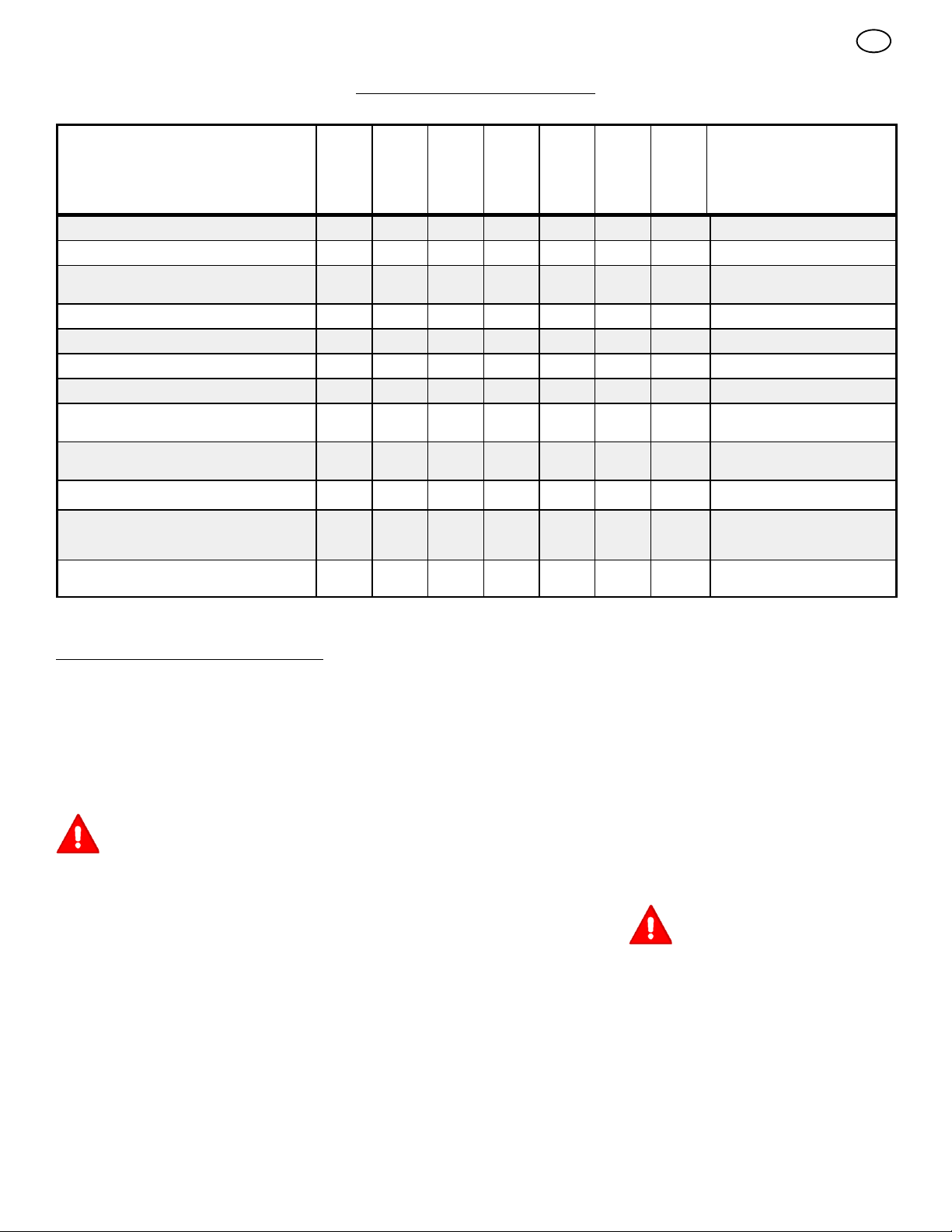
RESPONSABILITES DE L’ACHETEUR
F
TABLEAU DE MAINTENANCE
REGISTRE DES OPERATIONS
Complétez l es dates au fur et à mesure
des opérations d’entretien régulier effec-
Vérification du niveau d’huile
Vidange de l’huile du moteur
Vérification et serrage de tous les boulons et
écrous
Vérification de la bougie d’allumage
Réglage de la courroie d’entraînement
Vérification du niveau d’essence
Vidage de l’essence
Vérification du câble d’embrayage de la fraise (voir Réglage des câbles)
Vérification du câble d’embrayage des roues
(voir Réglage des câbles)
Lubrification de tous les points d’articulation
Lubrification de l’axe de la fraise hélicoïdale
(voir Remplacement du boulon de cisaillement)
Lubrification des chaînes d’entraînement et
des pignons
D’ENTRETIEN
tuées.
Avant
chaque
utilisa-
tion
2premières
heures
Toutes
les
5heu-
res
Toutes
les
10
heures
Toutes
les
25
heures
√ √ √
√ √
√ √
√ √
√ √ √
√
√ √
√ √
√
√ √
√ √
Chaque
saison
Avant
remisa-
ge
√
√
DATES DES OPERATIONS
D’ENTRETIEN
ENTRETIEN
REMARQUE : Des illustrations sont
présentes à la page 2 et sur les pages 57 à
62.
Utiliser la section Entretien suivante pour maintenir votre machine en bonne condition de fonctionnement. Toutes les informations concernant
le moteur figurent dans le guide du fabricant du
moteur. Lisez ce guide avant de démarrer le moteur.
DANGER : Avant d’effectuer toute
inspection, tout réglage (sauf celui
du carburateur), ou toute réparation, débrancher le fil de la bougie d’allumage.
Recommandations d’ordre général
La garantie de ce chasse--neige ne couvre pas
les pièces ayant fait l’objet d’abus ou de négligence de la part de l’utilisateur. Pour bénéficier
entièrement de la garantie, l’utilisateur doit entretenir le chasse--neige comme indiqué dans ce
manuel.
Certains réglages doivent être effectués régulièrement afin de maintenir le chasse--neige en bon
état.
Après chaque utilisation
G Détecter toute pièce desserrée ou endom-
magée.
G Resserrer toute fixation desserrée.
G Vérifier et entretenir la fraise.
G Contrôler les commandes pour vérifier si
elles fonctionnent toutes correctement.
G Remplacer immédiatement toute pièce usée
ou endommagée.
G Vérifier toutes les étiquettes et autocollants
de sécurité et d’instructions. Remplacer tout
autocollant ou étiquette manquant ou
difficilement lisible.
Tous les réglages figurant dans la section Entre-
tien de ce manuel doivent être vérifiés au moins
une fois par saison.
Obligatoire
Les réglages suivants doivent être vérifiés plus
d’une fois par saison.
1. Régler la courroie d’entraînement de la fraise
après les 2 ou 4 premières heures d’utilisation, une seconde fois au milieu de la saison,
et deux fois à chaque saison suivante. Voir
“Réglage de la courroie d’entraînement de la
fraise” dans la section Entretien.
Lubrification
Toutesles10heures(Figure 14)
1. Lubrifier les embouts graisseurs Zerk (1)
toutes les dix heures avec un pistolet à graisse.
24
2. A chaque remplacement d’une vis de cisaillement, l’axe de la fraise doit également être
graissé.
3. Lubrifier toutes les articulations.
Toutesles25heures
Engrenage de rotation de la cheminée
(Figure 6) Lubrifier l’engrenage de rotation de la
cheminée (1) avec de l’huile pour moteur d’automobile.
Chaînes
1. (Figure 1) Mettre la manette d’accélération
(6) en première vitesse.
2. Vider l’essence du réservoir. Placer le chasse--neige verticalement sur l’avant du carter
de la fraise (4).
DANGER : vider l’essence en plein
air, à l’écart de toute source de
flammesoudefeu.
3. (Figure 22) Dévisser les boulons (3) de
chaque côté du panneau ventral (2).
4. Retirer le panneau ventral (2).
5. (Figure 15) Graisser les chaînes (5) à l’aide
d’un lubrifiant pour chaînes.
6. Frotter l’arbre hexagonal et les pignons (6)
avec de l’huile moteur 5W30.
REMARQUE: Si de la graisse ou de l’huile
entre en contact avec le plateau d’entraînement du disque (1) ou de la roue de
friction (3), des dommages peuvent en
résulter. Eliminer toute trace d’huile ou de
graisse à l’aide d’un solvant à base d’alcool.
Page 25

7. (Figure 22) Monter le panneau ventral (2).
8. Resserrer les boulons (3) de chaque côté
du panneau ventral (2).
Piècesànepaslubrifier(Figure 15)
1. Ne pas graisser l’arbre hexagonal et le pignon (6). Toutes les bagues et les roule-
ments s ont lubrifiés à vie. Pour le remisage,
verser une légère quantité d’huile moteur
5W--30 sur un chiffon et essuyer l’arbre
hexagonal et le pignon (6) afin d’éviter la
rouille.
2. Si la graisse entre en contact avec la roue
de friction de caoutchouc (3) ou le plateau
d’entraînement du disque (1), la roue de
friction de caoutchouc (3) peut être en-
dommagé. Veiller à bien nettoyer la roue de
friction de caoutchouc (3) et le plateau
d’entraînement du disque (1).
ATTENTION : tout huilage ou graissage
des composants mentionnés ci--dessus
peut atteindre la roue de friction de caoutchouc (3). Si la roue de friction de caoutchouc (3) ou le plateau d’entraînement du
disque (1) sont souillés de graisse ou
d’huile, la roue de friction en sera endommagé.
3. La boîte de vitesse de la fraise a été lubrifiée
lors de la fabrication et ne requiert pas de
graissage supplémentaire. Si pour quelque
raison le lubrifiant de la boîte se met à fuir,
faites vérifier la boîte par un centre de maintenance agréé.
Réglagedelahauteurdespatins
(Figure 1)
Ce chasse--neige est équipé de deux patins de
réglagedehauteur(7). Ces patins servent à
élever l’avant du chasse--neige. Sur surfaces
dures normales telles que les voies de garage et
les trottoirs, régler les patins c omme suit.
1. Placer le chasse neige sur une surface plane.
2. Veiller à ce que les deux pneumatiques
soient de pression égale. La pression correcte s’échelonne de 14 PSI (1 BAR) à 17 PSI
(1.25 BAR). Ne pas excéder la pression
maximale indiquée sur le flanc du pneumatique.
3. Placer les boulons de cisaillement supplémentaires (fournis dans le sac de pièces)
au--dessous de chaque bout du bord d’atta-
que (15) attenant aux patins de réglage (7).
4. Dévisser les écrous de montage (16) main tenant les patins de réglage (7). Pour abaisser l’avant du chasse--neige, lever chacun
des patins de réglage (7). Resserrer les
écrous de montage (16).
REMARQUE : sur surfaces graveleuses ou
inégales, lever l’avant du chasse--neige en
abaissant les patins de réglage (7).
DANGER : Toujours maintenir une
garde au sol appropriée en fonc-
tion de la surface de travail. Des
objets comme du gravier, des pierres et
d’autres débris peuvent être pris par l’impulseur et projetés avec une force suffisante pour provoquer des blessures ou des
dégâts sur le chasse--neige.
Réglage du bord d’attaque (Figure 1)
Après une longue utilisation, le bord d’attaque
(15) s’use. Le bord d’attaque (15) et les patins
doivent toujours être réglés pour placer le bord
d’attaque (15) à 1/8 pouce (3 mm) au--dessus
de la surface à déneiger.
1. Placer le chasse neige sur une surface plane.
2. Veiller à ce que les deux pneumatiques
soient de pression égale. La pression correcte s’échelonne de 14 PSI (1 BAR) à 17 PSI
(1.25 BAR). Ne pas excéder la pression
maximale indiquée sur le flanc du pneumatique.
3. Desserrer les boulons et les écrous fixant le
bord d’attaque (15) au carterdelafraise
(4).
4. Régler le bord d’attaque (15) de façon à
placer le bord d’attaque (15) à 1/8 pouce (3
mm) au--dessus de la surface à déneiger
5. Resserrer les boulons et les écrous en s’assurant que le bord d’attaque (15) est paral-
lèle au trottoir ou à la surface à déneiger
6. Pour en prolonger l’utilisation du bord d’atta-
que (15),démonter le bord d’attaque (15) et
inverser le sens de montage.
.
.
Vérification et réglage des câbles
Le câble d’entraînement des roues et le câble
d’entraînement de la fraise hélicoïdale sont réglés dans l’usine de fabrication. En usage normal, un câble peut se détendre et doit être
vérifiéetréglécommesuit.
Vérification des câbles (Figure 16)
1. Pour vérifier le réglage, détacher le crochet
en “Z” du levier d’entraînement (2).
2. Pousser le levier d’entraînement (2) complètement vers l’avant jusqu’à ce que le le-
vier d’entraînement (2) entre en contact
avec la butée en plastique (3).
3. Le câble de commande est correctement
réglé si le crochet en “Z” (1) est aligné (4)
avec le trou du levier d’entraînement (2) et
que le câble ne présente pas d’affaissement.
Réglage du câble d’entraînement de la fraise
1. Vider l’essence du réservoir. Mettre le chasse--neige debout sur l’avant du carter de la
fraise.
DANGER : Vider l’essence à l’extérieur et à l’écart de toute source de
flammesoudefeu.
2. (Figure 16) Détacher le crochet en “Z” (1)
du levier d’entraînement (2).
3. (Figure 17) Relever le couvercle du ressort
de façon à exposer le ressort (5). Pousser le
câble (6) dans le ressort (5) pour exposer
l’extrémité carrée (7) du câble (6).
4. Tenir l’extrémité carrée (7) avec des pinces
et tourner l’écrou (8) dans un sens ou dans
l’autre jusqu’à ce que l’affaissement du câble
disparaisse.
5. Tirer le câble (6) dans le ressort (5) et le
remonter.
6. (Figure 16) Rattacher le crochet en “Z” (1)
au levier d’entraînement (2).
REMARQUE : lors du réglage ou du remplacement de la courroie d’entraînement de la
fraise hélicoïdale, vérifier et régler le câble.
25
F
Réglage du câble d’entraînement
1. Retirer le carburant du réservoir d’essence.
Positionner le chasse--neige debout sur la
face avant du carter de la fraise.
DANGER : Vider l’essence à l’extérieur, à l’écart de toute source de
flammesoudefeu.
2. (Figure 22) Desserrer les boulons (3) sur
chaque côté du panneau ventral (2).
3. Retirer le panneau ventral (2).
4. (Figure 16) Détacher le crochet en “Z” (1)
du levier d’entraînement de la fraise (2).
5. (Figure 27) Faire glisser la gaine du câble
(3) de l’attache de réglage du câble (4).
6. Enfoncer la base du câble de commande
de la fraise (5) dans l’attache de réglage
du câble (4) jusqu’à ce que le crochet en
“Z” (6) puisse être enlevé.
7. Retirer le crochet en “Z” (6) de l’attache de
réglage du câble (4).Placerlecrochet en
“Z” (6) dans le trou de réglage situé immé-
diatement au--dessous.
8. Tirer le câble de commande de la fraise (5)
vers le haut au travers de l’attache de régla-
ge du câble (4).
9. Replacer la gaine du câble (3) sur l’attache
de réglage du câble(4).
10.(Figure 16) Accrocher le crochet en “Z” (1)
au levier d’entraînement de la fraise (2).
11. (Figure 15) Pour vérifier le réglage, abaisser
le levier d’entraînement et vérifier la lon-
gueur “A” du ressort du câble d’entraînement (7). Lorsque le réglage est correct, la
longueur “A” du ressort du câble d’entraînement (7) doit être la suivante :
minimum 3 pouces (76 mm.)
maximum 3 pouces et 3/8 (85 mm.).
12.(Figure 22) Remonter le panneau ventral
(2).
13.Serrer les boulons (3) sur chaque côté du
panneau ventral (2).
Réglage des courroies
Les courroies s’étirent en usage normal. S i des
réglages deviennent nécessaires en raison de
l’usure ou de l’étirement, procéder comme suit.
Réglage de la courroie d’entraînement de la
fraise hélicoïdale
Si le chasse--neige n’éjecte pas la neige, vérifier
le réglage du câble d’entraînement de la fraise.
Voir “Vérification et réglage des câbles” dans la
section Entretien. Si le réglage est correct, vérifier l’état de la courroie d’entraînement de la fraise. Si celle--ci est endommagée ou lâche, la
remplacer. Voir “Remplacement des courroies”
dans la section Entretien. Si la courroie est détendue, la régler comme suit.
1. Débrancher le fil de la bougie d’allumage.
2. (Figure 18) Retirer la vis (2) du carter de la
courroie (1). Retirer la carterdelacourroie
(1).
3. (Figure 19) Desserrer l’écrou (2) sur la poulie libre (3) et pousser la poulie libre (3)
vers la courroie d’entraînement de la fraise (4) d’environ 1/8 pouce (3 mm).
4. Resserrer les écrous (2).
5. (Figure 21) Débrayer le levier d’entraînement de la fraise. Vérifier la tension de la
courroie d’entraînement de la fraise (4).
La courroie de la fraise (4) doit normalement fléchir d’environ 1/2 pouce (12,5 mm)
(5) sous une pression moyenne. Si la tension
n’est pas appropriée, répéter l’opération de
réglage.
Page 26

6. (Figure 18) Remonter le couvercle de la
courroie (1). Resserrer la vis (2).
7. Vérifier le réglage du câble d’entraînement
de la fraise. Voir “Vérification et réglage des
câbles” dans la section Entretien de ce manuel.
8. Rebrancher le fil de la bougie.
Courroie d’entraînement des roues
La courroie d’entraînement des roues est soumise à la pression constante d’un ressort et n’exige aucun réglage. Si la courroie d’entraînement
des roues patine, remplacer la courroie. Voir
“Remplacement des courroies” dans la section
Entretien de ce manuel.
Remplacement des courroies
Les courroies d’entraînement sont de construction adaptée et doivent être remplacées par des
courroies d’origine disponibles dans votre centre
de maintenance agréé le plus proche.
Certaines étapes requièrent l’assistance d’une
seconde personne.
Démontage de la courroie d’entraînement de la
fraise hélicoïdale
Si la la courroie d’entraînement de la fraise est
endommagée, le chasse--neige ne déverse pas
de neige. Remplacer la courroie endommagée
comme suit.
1. Débrancher le fil de la bougie.
2. (Figure 22) Desserrer les boulons (3) sur
chaque côté du panneau ventral (2).
3. Retirer le panneau ventral (2).
4. (Figure 18) Retirer la vis (2) du carter de la
courroie (1). Déposer le carterdelacourroie (1).
5. (Figure 19) Desserrer le guide de courroie
(9).Écarterleguide de courroie (9) de la
poulie d’entraînement de la fraise (10).
6. Séparer la poulie libre (3) de la courroie
d’entraînement de la fraise (4) et faire
glisser la courroie d’entraînement de la
fraise (4) de la poulie libre (3).
7. Enlever la courroie d’entraînement de la
fraise (4) de la poulie du moteur (11). Afin
d’enlever la courroie d’entraînement de la
fraise (4), on devra peut--être être partielle-
ment faire pivoter la poulie du moteur (11) .
8. (Figure 20) Enlever les quatre boulons (21)
du haut qui maintiennent le carter des
lames (22) et boîtier moteur (23). Dévisser
les deux boulons (24) du bas. Le carter des
lames (22) et le boîtier moteur (23) peuvent
maintenant être démontés pour enlever la
courroie.
9. (Figure 19) Enlever la vieille courroie d’en-
traînement de la fraise (4) de la poulie
d’entraînement de la fraise (10). Remplac-
courroie d’entraînement de la fraise
er la
(4) par une courroie de rechange provenant
de l’usine et disponible dans un centre de
réparation agréé.
10.Installer la nouvelle courroie d’entraîne-
ment de la fraise (4) sur la poulie d’entraînement de la fraise (10).
11.Remonter le carter des lames (22) sur le
boîtir moteur (23) avec les quatre boulons
(21) qui ont été enlevés dans l’étape 8. Bien
serrer les deux boulons du bas (24).
12.Installer la courroie d’entraînement de la
fraise (4) sur la courroie du moteur (11).
13.Faire glisser la courroie d’entraînement de
la fraise (4) sous la courroie libre (3).
14.Régler la courroie d’entraînement de la
fraise (4). Voir “Réglage de la courroie d’entraînement de la fraise” dans la section Entretien.
15.Régler le guide de courroie (9). Voir “Réglage du guide de courroie” dans la section Entretien.
16.(Figure 18) Monter le carter de courroie
(1). Serrer la vis (2).
17.Vérifier le réglage des câbles. Voir “Vérification du réglage des câbles” dans la section
Entretien.
18.Rebrancher le fil de la bougie.
Démontage de la courroie d’entraînement des
roues.
Si le chasse--neige n’avance pas, vérifier la
courroie d’entraînement des roue pour détecter
tout dommage ou toute usure. Si celle--ci est
endommagée ou usée, la remplacer comme
suit.
1. Débrancher le fil de la bougie.
2. Retirer la courroie d’entraînement de la fraise. Voir “Démontage de la courroie d’entraînement de la fraise” dans la section
Entretien.
3. (Figure 19) Retirer la bague de retenue (17)
de l’une des extrémités de la biellette d’axe
de la plaque de roulement (18). Retirer la
biellette d’axe de la plaque de roulement
(18) pour permettre à la plaque de roulement
de tourner en avant.
4. Retirer le ressort du câble de traction (16).
5. Dégager la courroie d’entraînement des
roues (13) de la poulie d’entraînement des
roues (14) et de la poulie motrice (15).
Remplacer la courroie d’entraînement des
roues (13) par une courroie d’origine dispo-
nible dans votre centre de maintenance
agréé le plus proche.
6. Monter la nouvelle courroie d’entraînement
des roues (13) sur la poulie d’entraînement des roues (14) et sur la poulie motrice (15).
7. Veiller à ce que la poulie libre d’entraînement des roues (12) soit correctement ali-
gnée avec la courroie d’entraînement des
roues (13).
8. Attacher le ressort du câble de traction
(16).
9. Monter la biellette d’axe de la plaque de
roulement (18) et la verrouiller à l’aide de la
bague de retenue (17) enlevée auparavant.
10.(Figure 30) La base de la plaque de roulement (20) doit être positionnée entre les encoches d’alignement (19). S’assurer que la
plaque de roulement (20) est correctement
fixée.
REMARQUE: Si l’entraînement des roues
ne fonctionne pas à la suite du remplacement de la courroie d’entraînement, vérifier que la plaque de roulement est bien
positionnée entre les encoches d’alignement (19).
11. (Figure 19) Monter et régler la courroie
d’entraînement de la fraise (4). Voir “Dé-
montage de la courroie d’entraînement de la
fraise” dans la section Entretien.
26
F
12.Régler le guide de courroie (9). Voir “Réglage du guide de courroie” dans la section Entretien.
13.(Figure 22) Remonter le panneau ventral
(2).
14.Serrer les boulons (3) sur chaque côté du
panneau ventral (2).
15.(Figure 18)Monter le carter de courroie (1).
Serrer la vis (2).
16.Vérifier le réglage des câbles. Voir “Vérification du réglage des câbles” dans la section
Entretien.
17.Brancher le fil de la bougie.
Réglage du guide de courroie
1. Débrancher le fil de la bougie.
2. (Figure 18) Retirer la vis (2). Déposer le
carterdelacourroie(1).
3. (Figure 1) Embrayer le levier d’entraîne-
ment de la fraise (5).
4. (Figure 23) Mesurer la distance entre le guide de courroie (2) et la courroie d’entraînement de la fraise (3)
correcte (4) doit être de 1/8 pouce
(3.175mm).
5. Si un réglage est nécessaire, desserrer les
boulons de montage du guide de courroie
(2)et placer le guide de courroie (2) en position correcte (4). Resserrer ensuite les
boulons du guide de courroie (2)
6. (Figure 18) Monter le carter de courroie
(1). Serrer la vis (2).
7. Rebrancher le fil de la bougie.
Réglage ou remplacement de la roue de
friction
Vérification de la roue de friction
Si le chasse--neige n’avance pas, vérifier la
courroie d’entraînement des roue, le câble d’entraînement des roues, ou la roue de friction. Si la
roue de friction est endommagé ou usé, il faut le
remplacer. Voir “Remplacement de la roue de
friction” dans cette section. Si la roue de friction
n’est pas endommagé ni usé, le vérifier comme
suit.
1. (Figure 1) Vider l’essence du réservoir. Mettre le chasse--neige debout sur l’avant du
carterdelafraise(4).
DANGER : vider l’essence à l’extérieur et à l’écart de toute source de
flammesoudefeu.
2. Débrancher le fil de la bougie.
3. (Figure 22) Desserrer les boulons (3) de
chaque côté du panneau ventral (2).
4. Retirer le panneau ventral (2).
5. (Figure 1) Mettre la manette d’accélération
(6) à la vitesse la plus basse.
6. (Figure 24) Noterlapositiondelaroue de
friction (4). La distance “A” correcte entre
le côté droit de la roue de friction (4) et l’extérieur du carter du moteur est la suivante:
Taille du pneu Distance “A”
12 et 13 pouces 4--1/8” (10,5 cm.)
16 pouces 4- 5/16” (10,95 cm.)
Si la roue de friction (4) n’est pas en position correcte, effectuer le réglage décrit ci-dessous.
Réglage de la roue de friction
7. (Figure 2) Positionner le levier de vitesse
(6) sur la vitesse de marche avant la plus
basse .
. La distance
Page 27

8. (Figure 9) Dévisser l’écrou de blocage
hexagonal (9) de la tige de sélection de vitesse (2). Enlever la rotule (6) de la tringle
du sélecteur de vitesse (7).
9. (Figure 24) Placer la roue de friction (4) en
position correcte.
10.(Figure 9) Faire tournber l’adapteur (10) jusqu’à ce que la rotule (6) soit alignée avec le
trou de montage de la tringle (7).Unefois
aligné, attacher la rotule (6) àlatringle (7).
11. (Figure 22) Remonter le panneau ventral
(2).
12.Serrer les boulons (3) de chaque côté du
panneau ventral (2).
Remplacement de la roue de friction
Le chasse--neige n’avance pas si la roue de friction est usé ou endommagé. La roue de friction
doit être remplacé comme suit.
1. (Figure 1) Vider l’essence du réservoir. Mettre le chasse--neige debout sur l’avant du
carterdelafraise(4).
DANGER : Vider l’essence à l’extérieur, à l’écart de toute source de
flammesoudefeu.
2. Débrancher le fil de la bougie.
3. (Figure 28) Retirer toutes les fixations attachant la roue gauche (10). Enlever la roue
gauche (10) de l’axe (11).
4. Desserrer les boulons (3) de chaque côté
du panneau ventral (2).
5. Retirer le panneau ventral(2).
6. (Figure 29) Retirer toutes les fixations attachant le pignon d’entraînement (12) àl’axe
(11).
7. Retirer la roue droite, l’axe (11),etlepignon
d’entraînement (12).
8. (Figure 30) Retirer les quatre boulons (16)
maintenant les roulements (7) de chaque
côté de l’arbre hexagonal (8).
9. (Figure 31) Retirer l’arbre hexagonal (8) et
les roulements (7).
REMARQUE : Bien se rappeler de la position des rondelles (17) .
10.(Figure 26) Retirer les trois fixations (4) attachant la roue de friction (5) au moyeu (6).
11. (Figure 26) Retirer la roue de friction (5) du
moyeu (6). Faire glisser la roue de friction
(5) de l’arbre hexagonal (8).
12.Monter la nouvelle roue de friction (5) sur le
moyeu (6) à l’aide des fixations retirées plus
tôt.
13.(Figure 31) Installer l’arbre hexagonal (8) et
les roulements (7) à l’aide des quatre boulons enlevés auparavant.
Veiller à ce que les rondelles (17) soient
correctement installées dans leur position
d’origine. Veuillez également vous assurer que les deux rondelles (13) sont correctement alignées avec les bras de
commande (14).
14.Veiller à ce que l’arbre hexagonal (8) puisse
tourner librement.
15.(Figure 29) Installer la roue droite, l’
et le pignon d’entraînement (12) à l’aide
des fixation retirées auparavant. Installer la
chaîne (15) sur le pignon d’entraînement
(12).
axe (11),
16.Vérifier le réglage de la roue de friction. Voir
“Réglage de la roue de friction” dans cette
section.
17.Veiller à ce que la roue de friction et le plateau d’entraînement du disque soient dépourvus d’huile ou de graisse.
18.(Figure 22) Remonter le panneau ventral
(2).
19.Resserrer les boulons (3) de chaque côté
du panneau ventral (2).
20.Monter la roue gauche (10) sur l’essieu (11)
à l’aide des fixations retirées plus tôt.
21.Rebrancher le fil de la bougie.
Remplacement d’un boulon de
cisaillement de la fraise hélicoïdale
Les fraises hélicoïdales sont fixées à l’arbre par
des boulons de cisaillement spéciaux qui sont
prévus pour casser si un objet se coince dans le
carter de la fraise. Ne pas utiliser un boulon
plus dur car ceci supprimera la protection du
boulon de cisaillement.
DANGER : Pour garantir la sécurité
et la protection de la machine,
seuls des boulons de cisaillement
d’origine doivent être utilisés pour leur
remplacement.
Pour remplacer un boulon de cisaillement cassé,
procéder comme suit. Des boulons de cisaillement de rechange sont fournis dans le sac de
pièces pour le montage.
1. (Figure 1) Placer l’interrupteur de sécurité
(13) à la position d’arrêt. Débrayer toutes les
commandes.
2. Débrancher le fil de la bougie et s’assurer
que toutes les pièces sont arrêtées.
3. (Figure 14) Si le chasse--neige en est équipé, graisser les embouts graisseurs Zerk
(1) de l’arbre de la fraise à l’aide d’un pistolet
graisseur.
4. (Figure 25) Aligner le trou de la fraise avec
le trou de son arbre. Monter le boulon de
cisaillement neuf (2),l’entretoise (3) et
l’écrou de blocage (4).
5. Rebrancher le fil de la bougie.
Préparation du chasse--neige pour le
remisage
DANGER : Ne pas retirer l’essence
à l’intérieur d’un bâtiment, près
d’un feu, ou en fumant une cigarette. Les gaz émis par l’essence peuvent provoquer une explosion ou un incendie.
Si la déneigeuse doit être entreposée pendant
une période prolongée, se référer au manuel de
fonctionnement du fabricant du moteur (inclus
avec certains modèles) pour obtenir d’importants détails d’entretien ou d’entreposage.
1. Vider le réservoir d’essence.
2. Faire tourner le moteur jusqu’à ce qu’il tombe
en panne sèche.
3. Ne jamais entreposer la déneigeuse avec de
l’essence dans le réservoir à l’intérieur d’un
bâtiment où des sources d’allumage sont
présentes, telles qu’un chauffe--eau ou un
radiateur, un séchoir à linge, et autres types
d’appareils similaires. Laisser le moteur refroidir avant l’entreposage dans un espace
clos.
27
F
4. Vidanger l’huile du moteur encore chaud.
Remplir le bloc--cylindre d’huile neuve.
5. Débrancher le fil de la bougie et verser environ 15 ml (1/2 oz) d’huile moteur dans le cylindre. Remplacer la bougie et faire tourner le
démarreur lentement pour distribuer l’huile.
6. Nettoyer complètement le chasse--neige.
7. Graisser tous les points de graissage (voir la
section Entretien).
8. S’assurer que tous les écrous, boulons et vis
sont fermement serrés. Vérifier toutes les
pièces mobiles pour déceler les indices de
dégâts et d’usure. Remplacer les pièces au
besoin.
9. Couvrir les pièces de métal du c arter de la
fraise hélicoïdale et de l’impulseur d’un produit antirouille.
10.Placer la machine dans un bâtiment bien
ventilé. Remiser dans un local propre et sec
et à l’écart de tout poël, chauffe--eau ou de
toute chaudière comportant une veilleuse ou
tout dispositif produisant des étincelles.
11.Si la machine doit être remisée à l’extérieur,
la monter sur des cales pour qu’elle ne repose pas au sol.
12.Couvrir ensuite le chasse--neige à l’aide
d’une bâche épaisse ne retenant pas l’humidité. Ne pas utiliser une bâche de matière
plastique.
Commande de pièces détachées
Le remplacement de pièces détachées est
montré soit au dos de ce manuel, soit dans un
manuel séparé de pièces de rechange.
Il est vivement recommandé de n’utiliser que
des pièces autorisées par le fabricant ou
approuvées. La lettre placée à la fin du numéro
de la pièce vous signale le type d’affinage pour
la pièce, C pour le chrome, Z pour le zinc, PA
pour une pièce achetée. Il est important de le
joindre lors de la commande d’une pièce. Ne
pas utiliser de pièces tractées ou d’accessoires
non spécifiquement prévus pour la
chasse--neige. Pour obtenir la pièce de
remplacement adéquate, il vous faut fournir le
numéro du modèle de la chasse--neige (Cf.
plaque indicatrice).
Pour obtenir des pièces de rechange, contacter :
BRIGGS AND STRATTON CANADA
Factory Customer Service
1195 Coutneypark Drive East
Mississauga, Ont. L5T--1R1
1--800--661--6662
Les appels en PCV ne seront pas acceptés.
Le remplacement des pièces comme le moteur,
les transmissions, la boîte--pont ou le différentiel,
sont disponibles depuis un service autorisé par
le fabricant, dont l’adresse peut être trouvée
dans les Pages jaunes. Par ailleurs, vous
pouvez vous appuyer sur les garanties
s’appliquant au moteur ou aux transmissions
pour commander les pièces de rechange.
Lors de la commande, vous devrez fournir les
informations suivantes :
(1) Le numéro du modèle
(2) Le numéro de série
(3)Lenumérodelapièce
(4) La quantité
Page 28

TABLEAU DE DEPANNAGE
PANNE CAUSE REPARATION
Démarrage difficile Bougie défective. Remplacer la bougie.
F
Eau ou impuretés dans le système de
distribution du carburant.
Le moteur tourne de manière irrégulière Conduit de carburant bouché, réservoir
Le moteur cale Machine fonctionnant avec le STARTER ouvert. Mettre le levier de starter en position de
Le moteur tourne de manière irrégulière;
Perte de puissance
Vibration excessive pièces dévissées : impulseur endommagé Arrêter le moteur immédiatement et débrancher
La machine ne se propulse pas
automatiquement
La machine n’éjecte pas de neige Courroie d’entraînement de la fraise lâche ou
d’essence vide, ou essence périmée
Eau ou impuretés dans le système de
distribution du carburant.
Courroie d’entraînement lâche ou endommagée. Remplacer la courroie d’entraînement.
Réglage incorrecte du câble d’entraînement des
roues.
Roue de friction usagé ou endommagé. Remplacer la roue de friction.
endommagée.
Câble de commande de la fraise non réglé
correctement.
Utiliser le drain de carburateur pour évacuer les
impuretés et remplir avec de l’essence neuve.
Nettoyer le conduit de carburant ; vérifier
l’arrivée du carburant ; ajouter de l’essence
neuve.
MARCHE.
Utiliser le drain de carburateur pour évacuer les
impuretés et remplir avec de l’essence neuve.
la bougie. Serrer tous les boulons et effectuer
les réparation nécessaires. Si la vibration
persiste, porter la machine à une personne
qualifiée pour la réparer.
Régler le câble d’entraînement des roues.
Régler la courroie d’entraînement de la fraise ;
la remplacer si elle est endommagée.
Régler le câble de commande de la fraise.
Boulon de cisaillement cassé Remplacer le boulon de cisaillement.
Déversoir bouché. Arrêter immédiatement le moteur et débrancher
Corps étranger coincé dans la fraise. Arrêter immédiatement le moteur et débrancher
le cordon de la bougie.
Nettoyer le déversoir et l’intérieur du carter de la
fraise.
le cordon de la bougie.
Retirer le corps étranger coincé dans la fraise.
28
Page 29

F
POLICE DE GARANTIE DU PROPRIÉTAIRE D’UN ÉQUIPEMENT DE BRIGGS & STRATTON CORPORATION
Date d’effet au 1er janvier 2006, annule et remplace toutes les garanties précédentes et les garanties antérieures au 1er janvier 2006
GARANTIE LIMITÉE
Briggs & Stratton Corporation remplacera ou réparera gratuitement la ou les pièces du produit présentant un défaut de matière ou de
construction ou les deux. Tous les frais de transport du produit destiné à être remplacé ou réparé au titre de la présente garantie restent à charge
de l’acheteur. Cette garantie est applicable pendant la période et aux conditions prévues dans le présent document. Pour toute intervention sous
garantie, recherchez le Réparateur Agréé le plus proche de chez vous grâce à la liste fournie sur notre site Internet www.murray.com.
IL N’EXISTE AUCUNE AUTRE GARANTIE EXPRESSE. LES GARANTIES, Y COMPRIS CELLES DE LA VALEUR MARCHANDE ET
D’ADAPTATION À UN OBJECTIF PARTICULIER, SONT LIMITÉES À UN AN À PARTIR DE LA DATE D’ACHAT OU À LA PÉRIODE LÉGALE
ADMISE. TOUTE GARANTIE AUTRE EST EXCLUE. NOTRE RESPONSABILITÉ AU TITRE DE TOUTES LES GARANTIES CONCERNANT
DES DÉGÂTS ACCIDENTELS OU PROVOQUÉS PAR L’ÉQUIPEMENT EST EXCLUE DANS LA LIMITE DES EXCLUSIONS AUTORISÉES
PAR LA LOI. Certains pays ou États n’autorisent pas la limitation de l a durée de la garantie implicite et certains pays ou États n’autorisent pas
l’exclusion ou la limitation des dégâts provoqués par accident ou consécutifs, ce qui fait que la limitation et l’exclusion ci-dessus peuvent ne pas
s’appliquer à vous. Cette garantie vous donne des droits légaux et vous pouvez bénéficier d’autres droits qui peuvent varier d’un pays à l’autre ou
d’un État à l’autre.
CONDITIONS DE LA GARANTIE
Marque/Unité privé professionnel particulière
Une phase déneigeuse 1 an 90 jours............... .................
Deux phases déneigeuse 2 an 90 jours............. .................
La période de garantie débute à la date d’achat par le premier acheteur de détail ou par le premier utilisateur commercial final, et couvre la durée stipulée
dans le tableau ci-dessus. Par « usage privé », on entend une utilisation personnelle résidentielle par l’acheteur de détail. Par « usage professionnel », on
entend toute autre utilisation, y compris à des fins commerciales, donnant lieu à rémunération ou location. Dès la première exploitation du produit en usage
professionnel, il est réputé être définitivement à usage professionnel au titre de la présente garantie.
Il n’est pas nécessaire d’enregistrer les produits de marque Murray pour bénéficier de la garantie. Conservez le ticket de caisse comme preuve d’achat. Si
vous ne pouvez pas fournir la preuve de la date d’achat initiale au moment de la demande de garantie, la date de fabrication du produit servira à déterminer
la période de garantie.
Usage Usage Condition
AU SUJET DE LA GARANTIE
Nous acceptons les réparations sous garantie et nous excusons des dérangements occasionnés. Tout Réparateur Agréé peut effectuer des réparations
sous garantie, dont la plupart sont effectuées normalement, mais certaines peuvent ne pas être acceptables. Par exemple, une réparation sous garantie
ne s’applique pas si le produit a été endommagé suite à une mauvaise utilisation, l’absence d’entretien normal, une expédition, une manutention, un
stockage ou une installation défectueuse. De même, la garantie est nulle si le numéro de série a été enlevé ou si le produit a été altéré ou modifié.
Cette garantie ne couvre que les défauts de matière ou de construction liés au produit. Afin d’éviter tout malentendu entre le client et le Réparateur
Agréé, sont énumérées ci-après certaines des causes de défaillance des produits qui ne sont pas couvertes par la garantie.
• Usure normale : les appareils équipés de petits moteurs, comme tous les appareils mécaniques, nécessitent un entretien régulier et le remplace-
ment des pièces d’usure pour fonctionner correctement. Cette garantie ne couvre pas la réparation de pièces ou de produits dont l’usure provient
d’un usage normal.
• Installation : cette garantie ne s’applique pas à un produit ayant fait l’objet d’une installation, altération ou modification inappropriée ou interdite ni
aux installations qui empêchent le démarrage et entraînent de mauvaises performances du moteur.
• Entretien inadéquat : la durée de vie de ce produit dépend des conditions dans lesquelles il est utilisé et de l’entretien qu’il reçoit. Les intervalles
d’entretien et de réglage recommandés sont indi qués dans le manuel d’utilisation. Les produits tels que motoculteurs, dresse-bordures ou tondeuses rotatives, sont utilisés dans un environnement poussiéreux ou sale, pouvant être la cause d’une usure qui peut sembler prématurée. Une telle
usure, lorsqu’elle est consécutive à l’entrée de poussière, sable ou autre produit abrasif en raison d’un mauvais entretien, n’est pas couverte par la
garantie. De même, la garantie ne couvre pas les réparations dues à des problèmes découlant du remplacement de pièces par des pièces non
d’origine.
• Insuffisance ou erreur de carburant ou de lubrifiant : cette garantie ne couvre pas les dommages provoqués par l’utilisation de c arburants éven-
tés ou d’essences modifiées. Les dommages subis par le moteur ou ses composants, à savoir chambre de combustion, soupapes, sièges de soupape, guides de soupape ou bobinage du démarreur grillé, suite à l’emploi de carburants de substitution tels que pétrole liquéfié ou gaz naturel, ne
sont pas couverts à moins que le moteur ne soit certifié pour cet usage. Les pièces qui seraient rayées ou cassées du fait d’un manque d’huile ou
d’une huile polluée ou dont le degré de viscosité est inadéquat, ainsi que les composants endommagés en raison d’un manque de lubrification ne
sont pas couverts.
• Utilisation inadéquate : le fonctionnement approprié du produit est stipulé dans le manuel d’utilisation. Ne sont pas couverts les cas suivants. Pro-
duit endommagé suite à un sur-régime, une surchauffe ou une utilisation dans un espace confiné où la ventilation est insuffisante. Bris du produit dû
à des vibrations excessives résultant d’un serrage insuffisant des boulons de fixation du moteur, d’une lame ou turbine desserrée ou mal équilibrée,
d’un sur-régime ou d’un vilebrequin faussé suite à un choc sur un corps dur. Dommages ou dysfonctionnements résultant d’accidents, utilisation
abusive, mauvais entretien, gel, détérioration chimique ainsi qu’usage en dehors des capacités recommandées stipulées dans le manuel d’utilisation.
• Mise au point normale, éléments d’usure ou réglages : cette garantie exclut les éléments d’usure tels que notamment huile, courroies, lames,
joints toriques, filtres.
• Autres exclusions : réparations ou réglages concernant des pièces non fabriquées par Briggs & Stratton Corporation, se reporter à la garantie
pour les fabricants respectifs. Ce tte garantie exclut les défaillances dues à des catastrophes naturelles et autres cas de force majeure hors
du contrôle des fabricants. Sont également exclus les produits usagés, reconditionnés et de démonstration.
La garantie ne peut être appliquée que par les Réparateurs Agréés, dont la liste se trouve sur www.murray .com.
29
Page 30

ALLGEMEINES
Bei dieser Bedienungsanleitung werden einige handwerkliche
Grundkenntnisse vorausgesetzt. Wie in den meisten
Wartungshandbüchern werden nicht alle Schritte beschrieben. Das
Lösen und Anziehen von Schrauben kann jeder ohne große
handwerkliche Fähigkeiten bewältigen. Lesen und befolgen Sie diese
Anweisungen, bevor Sie das Gerät benutzen.
Informieren Sie sich über Ihr Produkt: Sie erzielen die beste Leistung,
wenn Sie das Gerät und dessen Funktionen verstehen. Beim Lesen
dieser Bedienungsanleitung vergleichen Sie die Abbildungen mit dem
Gerät. Machen Sie sich mit der Anordnung und Funktion der
Bedienelemente vertraut. Befolgen Sie die Anweisungen zum Betrieb
und die Sicherheitshinweise, um einen Unfall zu verhindern. Bewahren
Sie diese Bedienungsanleitung auf, um später darauf zurückgreifen zu
können.
WICHTIG: Viele Geräte sind nicht vollständig zusammengebaut und
werden in Kartons verpackt verkauft. Der Eigentümer muss die
Montageanweisungen in dieser Bedienungsanleitung genau befolgen.
Andere Geräte werden im vor--montierten Zustand verkauft. Bei
montierten Geräten ist der Eigentümer dafür verantwortlich zu prüfen, ob
das Gerät korrekt montiert ist. Der Eigentümer muss das Gerät vor dem
ersten Gebrauch entsprechend der Anweisungen in dieser
Bedienungsanleitung sorgfältig prüfen.
D
Bedienelement & Gerätefunktionen (siehe Abbildung 1)
Auswurfkurbel (2) - Ändert die Richtung des Aeuswurfkamins.
Auswurfumlenkvorrichtung (3) - Ändert den Abstand, in dem der
Schnee ausgeworfen wird.
Auswurfkamin (4) - Ändert die Richtung, in die der Schnee
ausgeworfen wird.
Räumwerkhebel (5) - Startet und hält die Frässchnecke und die
Wurfeinrichtung an (Sammeln und Auswerfen des Schnees).
Motorfunktionen
Stoppschalter (8) - Muss in die Position AN geschoben werden, um
Motor zu starten.
Initialzündungsknopf (9) - Spritzt Benzin direkt in den Vergaser ein,
damit Motor bei kaltem Wetter schnell anspringt.
Rückstarterhebel (12) - Zum manuellen Anlassen des Motors.
Choke (14) - Zum Anlassen eines kalten Motors.
Angegebene Vibrationsemissionswerte gemäß Richtlinie 98/37/EC.
Vibrationsemission gemäß EN 1033;1996: 5,9
Werte ermittelt am Griff während Gerät stationär auf einer Betonfläche mit 3700
min--1 betrieben wurde.
Angegebene Geräuschemissionen von Lw
Anhang V.
Schalldruckpegel an Bedienerposition: 87
Werte am Ohr gemäß den Spezifikationen in EN ISO 11201 ermittelt.
Angegebener
Geräuschemissions--Schalld
ruckpegel von 104 dB(A)
erfüllt Richtlinie 2000/14/EC.
m/s2.
A 104 dB erfüllen Richtlinie 2000/14/EC,
dB.
30
Page 31

Dieses Handbuch beinhaltet
Sicherheitsinformationen, um Ihnen die Gefahren
und Risiken im Zusammenhang mit Schneefräsen
bewusst zu machen, und Ihnen zu vermitteln, wie man sie
vermeidet. Die Schneefräse wurde zur Räumung von Schnee
entwickelt und sollte zu keinem anderen Zweck verwendet werden.
Es ist wichtig, dass Sie sich diese Anleitung gut durchlesen und sie
verstehen, und ebenso sollte jeder, der mit dem Gerät arbeitet,
diese Anleitung lesen und verstehen.
WARNUNG
Die Motorabgase dieses Produkts enthalten Chemikalien, von denen im
Staat Kalifornien bekannt ist, dass sie Krebs, Geburtsfehler hervorraufen
und andere negative Auswirkungen auf die Fortpflanzung haben können.
Ein Signalwort (GEFAHR, WARNUNG oder VORSICHT) wird zusammen mit
dem Warnsymbol verwendet, um die Wahrscheinlichkeit und die potentielle
Schwere von Verletzungen anzuzeigen. Außerdem kann ein Gefahrensymbol
verwendet werden, um den Gefahrentyp darzustellen
GEFAHR weist auf eine Gefährdung hin, deren
Nichtbeachtungzum Tod oder zu schweren Verletzungen
führen kann.
WARNUNG weist auf eine Gefährdung hin, deren
Nichtbeachtung zum Tod oder zu schweren Verletzungen
führen könnte.
VORSICHT weist auf eine Gefährdung hin, deren
Nichtbeachtung zum Tod oder zu leichten bis mittelschweren
Verletzungen führen könnte.
Wird VORSICHT ohne das Warnsymbol verwendet, weist dies
auf eine Situation hin, die zu Schäden am Gerät führen
könnte.
Gefahrensymbole und ihre Bedeutungen
Diese Symbole werden an Ihrem Gerät verwendet und sind in Ihrer
Bedienungsanleitung definiert. Lesen Sie zu ihren Bedeutungen nach und
merken Sie sich diese. Die Verwendung dieser Symbole in Verbindung mit
einem Signalwort wird Sie auf potentielle Gefahren und deren Vermeidung
hinweisen.
D
Betriebssymbole und ihre Bedeutungen
Diese Symbole werden an Ihrem Gerät verwendet und sind in Ihrer
Bedienungsanleitung definiert. Es ist wichtig, dass Sie die Bedeutungen lesen
und verstehen. Ein Nichtverstehen der Symbole kann zu Verletzungen führen.
Öl
Kraftstoff
Ein Aus
Primerkopf
Gashebel
Choke auf
Choke ein
Stop
Langsam
Schnell
Einkuppeln
Vorwärts
Neutral
Rückwärts
Zündung ein
Zündung aus
Zündschlüssel
Drücken, um den
elektrischen Start
einzukuppeln
Elektrischer
Start
Motorstart
Sicherheitswarnung – identifiziert
Sicherheitsinformationen zu Gefahren, die zu
Verletzungen an Personen führen können.
Bedienungsanleitung – Lesen Sie diese bevor Sie
jegliche Aktivitäten durchführen oder das Gerät
betreiben.
Rotierende
Schnecke
Rotierendes
Gebläserad
Toxische Gase
Rotierende
Getriebe
Hochfliegende
Objekte
Sicherheitsabstand
zum Gerät einhalten.
Schalten Die den Motor ab und entfernen Sie den
Zündkerzenstecker, bevor Sie Wartungs- oder
Reparaturarbeiten durchführen.
Feuer
Explosion
Schock
Heiße
Oberfläche
Nicht in rotierende
Teile greifen.
Empfohlener
Gehörschutz für die
längere Verwendung.
31
Einkuppeln
Antrieb
Schneckensammler
Schneckenkupplung
Antriebskupplung
Auswurfkanal
LINKS HINAUF
RECHTS
Kanalleitblech
Betrieb des
Motors
Motor aus
Einkuppeln
Auskuppeln
Beheizte Griffe
HERUNTER
Page 32

WARNUNG: Diese Maschine kann Hände und Füße abschneiden und Objekte schleudern. Lesen Sie sich
diese Regeln durch und befolgen Sie sie strikt. Eine Nichteinhaltung dieser Regeln kann dazu führen, dass
Sie die Kontrolle über das Gerät verlieren, was zu schweren Verletzungen an Ihrer Person und anderen
Personen oder zum Tod führen kann und Sachschäden verursachen kann. Das Dreieck im Text stellt
wichtige Warnungen dar, die unbedingt befolgt werden müssen.
REGELN FÜR DEN SICHEREN BETRIEB
Sichere Betriebspraktiken für Schneefräsen
WICHTIG: Die Sicherheitsstandards erfordern
Bediener--Anwesenheitskontrollen, um das Verletzungsrisiko zu
minimieren. Ihre Schneefräse ist mit solchen Kontrollen ausgestattet.
Versuchen Sie unter keinen Umständen die Funktion der
Bediener--Anwesenheitskontrolle zu unterdrücken.
Übung
1. Lesen, verstehen und befolgen Sie alle Anweisungen an der Maschine
und in den Handbüchern, bevor Sie dieses Gerät betreiben. Seien Sie
sehr sorgfältig mit den Kontrollen und der ordnungsgemäßen
Verwendung des Gerätes. Sie müssen wissen wie Sie die Einheit
schnell s toppen und die Kontrollen schnell auskuppeln können.
2. Lassen Sie das Gerät nie von Kindern betreiben. Lassen Sie nie
Erwachsene dieses Gerät betreiben, ohne sie ordnungsgemäß
einzuweisen.
3. Halten Sie den Betriebsbereich frei von Personen, insbesondere von
kleinen Kindern und Haustieren.
4. Gehen Sie vorsichtig vor, um ein Ausrutschen oder Fallen zu
vermeiden, wenn Sie das Gerät im Rückwärtsgang betreiben.
Vorbereitung
1. Untersuchen Sie den Bereich, in dem das Gerät verwendet werden soll,
sorgfältig und entfernen Sie alle Fußabtreter, Schlitten, Bretter, Drähte
und andere Fremdkörper.
2. Kuppeln Sie alle Kupplungen aus und schalten Sie auf Neutral, bevor
Sie den Motor starten.
3. Betreiben Sie das Gerät nicht ohne geeignete Winterkleidung. Tragen
Sie Schuhwerk, das die Trittfestigkeit auf glatten Oberflächen erhöht.
Vermeiden Sie lockere Kleidung, die zwischen die sich bewegenden
Teile geraten könnten.
4. Gehen Sie sorgfältig mit dem Kraftstoff um, er ist hochentzündlich.
a. Verwenden Sie einen zulässigen Kraftstoffbehälter.
b. Füllen Sie niemals Kraftstoff in einen laufenden oder heißen Motor
nach.
c. Befüllen Sie den Kraftstofftank sehr vorsichtig. Befüllen Sie den
Kraftstofftank nie im Haus. Schrauben Sie den Tankdeckel wieder fest
und wischen Sie verschütteten Kraftstoff ab.
d. Befüllen Sie Behälter nie innerhalb eines Fahrzeugs oder auf einem
LKW oder Anhänger mit Kunststoffdichtung. Stellen Sie den Behälter
immer auf den Boden, von Ihrem Fahrzeug entfernt, bevor Sie ihn
befüllen.
e. Wenn praktikabel, entfernen Sie gasgetriebene Geräte vom LKW
oder Anhänger und betanken Sie diese auf dem Boden. Falls das
nicht möglich ist, tanken Sie es lieber auf einem Anhänger auf als von
einer Kraftstoffdispenserdüse.
f. Achten Sie darauf, dass die Düse bis zum Ende des Auftankens
immer mit dem Rand des Kraftstofftank oder Behälters im Kontakt
bleibt. Verwenden Sie kein Gerät mit Düsenverriegelung.
g. Schrauben Sie den Tankdeckel wieder fest und wischen Sie
verschütteten Kraftstoff ab.
h. Falls Kraftstoff auf Ihre Kleidung gelangt, wechseln Sie diese bitte
sofort.
5. Verwenden Sie Verlängerungskabel und Anschlüsse wie vom
Hersteller angegeben für alle Einheiten mit Antriebsmotoren oder
elektrischen Startmotoren.
D
6. Stellen Sie die Höhe des Sammler--Gehäuses auf Schotter oder
Kiesoberflächen ein.
7. Versuchen Sie nie irgendwelche Einstellungen bei laufendem Motor
vorzunehmen (es sei denn dies wird speziell durch den Hersteller
empfohlen).
8. Warten Sie, bis sich Motor und Schneefräse an die Außentemperaturen
angepasst haben, bevor Sie mit dem Schneeräumen beginnen.
9. Tragen Sie beim Betrieb der Schneefräse sowie bei Einstellungen und
Reparaturen immer eine Sicherheitsbrille oder einen Augenschutz, um
Ihre Augen vor Fremdkörpern zu schützen, welche die Maschine
schleudert.
Betrieb
1. Halten Sie Hände und Füße von rotierenden Teilen fern. Halten Sie sich
immer von der Entladeöffnung fern.
2. Gehen Sie äußerst vorsichtig vor, wenn Sie auf Schotterwegen oder
Schotterstraßen arbeiten oder diese überqueren. Achten Sie auf
verborgene Gefahren und Verkehr.
3. Stoppen Sie den Motor, wenn Sie einen Fremdkörper berührt haben,
schalten Sie den Motor ab, ziehen Sie Zündkabel ab, entfernen Sie das
Kabel an Elektromotoren, untersuchen Sie die Schneefräse auf jegliche
Schäden, und reparieren Sie den Schaden, bevor Sie die Schneefräse
erneut starten und betreiben.
4. Falls die Einheit beim Start abnormal vibriert, stoppen Sie den Motor
und suchen Sie sofort nach der Ursache. Vibration ist in der Regel ein
Warnhinweis für Probleme.
5. Stoppen Sie den Motor, wann immer Sie die Betriebsposition verlassen,
bevor Sie den Sammler/das Gebläserad--Gehäuse oder den
Auswurfkanal von der Verstopfung befreien und wenn Sie irgendwelche
Reparaturen, Einstellungen oder Untersuchungen vornehmen.
6. Stellen Sie beim Reinigen, Reparieren oder Untersuchen sicher, dass
der Sammler/das Gebläserad und alle beweglichen Teile gestoppt
haben. Ziehen Sie das Zündkabel ab und halten Sie das Kabel von der
Zündkerze fern, um ein zufälliges Starten zu vermeiden.
7. Lassen Sie den Motor nicht im Haus laufen, außer beim Start des
Motors und zum Transport der Schneefräse in das Gebäude hinein
oder aus dem Gebäude heraus. Öffnen Sie die Außentüren; Abgase
sind gefährlich (sie enthalten KOHLENMONOXID, ein GERUCHLOSES
und TÖDLICHES GAS).
8. Gehen Sie besonders vorsichtig vor, wenn Sie an Abhängen arbeiten.
Versuchen Sie nicht, Schnee an steilen Abhängen zu beräumen.
9. Betreiben Sie die Schneefräse nie ohne geeignete Schutzgitter, Platten
oder andere Sicherheitsvorrichtungen am Gerät.
10. Richten Sie den Auswurfkanal niemals auf Menschen oder Bereichewo
Sachschäden entstehen können. Halten Sie Kinder un andere
Personen fern.
11. Überlasten Sie die Maschinenkapazität nicht, indem Sie versuchen den
Schnee zu schnell zu beräumen.
12. Betreiben Sie die Maschine nie bei hohen Transportgeschwindigkeiten
auf glatten Oberflächen. Sehen Sie nach hinten und gehen Sie
vorsichtig vor, wenn Sie im Rückwärtsgang arbeiten.
13. Schalten Sie die Stromzufuhr zum Sammler/Gebläserad aus, wenn die
Schneefräse transportiert oder nicht betrieben wird.
14. Verwenden Sie nur vom Hersteller der Schneefräse zugelassenes
Zubehör und Ersatzteile (wie Kabinen, Radketten etc.).
32
Page 33

15. Betreiben Sie die Schneefräse nie ohne gute Sichtbarkeit oder Licht.
Stellen Sie immer sicher, dass Sie trittfestes Schuhwerk anhaben und
die Griffe richtig festhalten. Gehen Sie, nicht rennen.
16. Berühren Sie niemals einen heißen Motor oder Schalldämpfer.
17. Betreiben Sie die Schneefräse nie in der Nähe von Glaswänden,
Fahrzeugen, Fensterschutzvorrichtungen, Abfalltonnen usw. ohne den
Schneewurfwinkel entsprechend einzustellen.
18. Richten Sie den Schneewurf nie auf Zuschauende und erlauben Sie
niemandem sich vor der Einheit aufzuhalten.
19. Belassen Sie eine laufende Einheit nie ohne Aufsicht. Kuppeln Sie
immer die Schnecke und die Zugsteuerungen aus, schalten Sie den
Motor ab und entfernen Sie die Schlüssel.
20. Betreiben Sie die Einheit nie unter Einfluss von Alkohol oder Drogen.
21. Denken Sie immer daran, dass die Bedienperson für alle Unfälle an
Personen und Sachwerten verantwortlich ist.
22. Daten weisen darauf hin, dass an einem großen Anteil aller
Stromgerät--bezogenen Verletzungen Personen ab einem alter von 60
Jahren beteiligt sind. Diese Bedienpersonen sollten ihre Fähigkeit die
Einheit sicher genug zu bedienen, um sich und andere vor
Verletzungen zu schützen, einschät zen, bevor sie das Gerät betreiben.
23. TRAGEN SIE KEINE langen Schals oder lockere Kleidung, die sich in
den beweglichen Teilen verfangen könnte.
24. Schnee kann Hindernisse verbergen. Stellen sie sicher, dass Sie alle
Hindernisse aus dem zu beräumenden Bereich entfernen.
Kinder
Tragische Unfälle können die Folge sein, wenn die Bedienperson nicht auf die
Anwesenheit von Kindern achtet. Kinder werden oft durch die Einheit und ihren Betrieb
angezogen. Nehmen Sie nie an, dass Kinder dort bleiben, wo Sie sie zuletzt gesehen
haben.
1. Halten Sie Kinder außerhalb des Bereiches und unter der sorgfältigen
Obhut eines anderen verantwortlichen Erwachsenen.
2. Seien Sie gewarnt und schalten Sie die Einheit ab, wenn Kinder den zu
beräumenden Bereich betreten.
3. Lassen Sie das Gerät nie von Kindern betreiben.
4. Seien Sie besonders vorsichtig, wenn Sie sich blinden Ecken, Büschen,
Bäumen oder anderen Objekten nähern, die den Blick behindern.
Freiräumen eines verstopften Auswurfkanal
Handkontakt mit dem rotierenden Gebläserad im Inneren des Auswurfkanal ist
die häufigste Ursache von Verletzungen im Zusammenhang mit Schneefräsen.
Reinigen Sie den Auswurfkanal niemals mit der Hand.
Um den Kanal zu reinigen:
1. SCHALTEN SIE DEN MOTOR AB.
2. Warten Sie 10 Sekunden, um sicher zu gehen, dass die Gebläseblätter
zu rotieren aufgehört haben.
3. Verwenden Sie i mmer ein Reinigungswerkzeug, nicht die Hände.
Service, Wartung und Lagerung
1. Überprüfen Sie die Schneidebolzen in häufigen Intervallen auf
Festigkeit, um sicher zu stellen, dass das Gerät in einem sicheren
Arbeitszustand ist.
2. Lagern Sie die Maschine niemals innerhalb eines Gebäudes, in dem
sich Zündquellen wie heißes Wasser und Heizkörper oder
Bekleidungstrockner befinden, wenn sich Kraftstoff im Tank befindet.
Lassen Sie den Motor abkühlen, bevor Sie das Gerät in irgendeiner
Einfriedung lagern.
D
3. Lesen Sie wichtige Details immer in der Bedienungsanleitung nach,
wenn die Schneefräse über einen längeren Zeitraum gelagert werden
soll.
4. Belassen Sie Sicherheits-- und Anleitungsetiketten an i hrem Platz oder
ersetzen Sie sie falls erforderlich.
5. Lassen Sie die Maschine nach der Schneeräumung einige Minuten
laufen, um ein Einfrieren des Sammlers/Gebläserades zu verhindern.
6. Falls Kraftstoff verschüttet wird, versuchen Sie nicht den Motor z u
starten, sondern bringen Sie die Maschine aus dem Bereich weg, in
dem der Kraftstoff verschüttet wurde, und vermeiden Sie die Schaffung
jeder Art von Zündquelle zu vermeiden, bis die Kraftstoffdämpfe sich
verzogen haben.
7. Verwenden Sie immer sichere Praktiken beim Auftanken und bei der
Handhabung von Kraftstoff , wenn Sie die Einheit nach Transport oder
Lagerung auftanken.
8. Befolgen Sie immer die Bedienungsanleitung, um das Gerät auf die
Lagerung sowohl für kurze als auch für längere Zeiträume
vorzubereiten.
9. Befolgen Sie immer die Anweisungen im Motor--Handbuch für
ordnungsgemäße Start-verfahren, wenn Sie die Einheit erneut
einsetzen.
10. Belassen Sie Sicherheits-- und Anleitungsetiketten an i hrem Platz oder
ersetzen Sie sie falls erforderlich.
11. Halten Sie Muttern und Schrauben fest angezogen und achten Sie
darauf, dass die Einheit im guten Zustand bleibt.
12. Manipulieren Sie nie an den Sicherheitsvorrichtungen herum.
Überprüfen Sie deren ordnungsgemäßen Betrieb regelmäßig und
nehmen Sie die nötigen Reparaturen vor, wenn sie nicht
ordnungsgemäß funktionieren.
13. Die Komponenten unterliegen Abnutzung, Schäden und Alterung.
Überprüfen Sie die Komponenten häufig und ersetzen Sie sie wenn
nötig durch vom Hersteller empfohlene Teile.
14. Überprüfen Sie den Kontrollbetrieb häufig. Nehmen Sie Einstellungen
und Wartungsarbeiten wie erforderlich vor.
15. Verwenden Sie nur vom Hersteller genehmigte Ersatzteile, wenn Sie
Reparaturen vornehmen.
16. Halten Sie sich bei allen Einstellungen und Korrekturen immer an die
Herstellerspezifikation.
17. Nur autorisierte Wartungsdienste sollten für größere Wartungsarbeiten
und Reparaturen genutzt werden.
18. Versuchen Sie nie größere Reparaturen an dieser Einheit
vorzunehmen, es sei denn Sie wurden entsprechend ausgebildet.
Unsachgemäße Wartungsprozeduren können zu gefährlichem Betrieb,
Schäden an der Einheit und zum Erlöschen der Herstellergarantie
führen.
19. Überprüfen Sie die Schneidebolzen in häufigen Intervallen auf
Festigkeit, um sicher zu stellen, dass das Gerät in einem sicheren
Arbeitszustand ist.
Abgase
1. Die Motorenabgase von diesem Produkt enthalten Chemikalien, von
denen bekannt ist, dass sie in bestimmter Menge Krebs, Geburtsfehler
oder negative Auswirkung auf die Fortpflanzung haben können.
2. Falls verfügbar, suchen Sie nach den relevanten Informationen zu
Emissionsgrenzwerten auf dem Motorenetikett.
Zündsystem
1. Dieses Zündkerzensystem entspricht der kanadischen Richtlinie
ICES-002.
33
Page 34

MONTAGE
Lesen und befolgen Sie die Anweisungen für
das Montieren und Einstellen Ihrer Schneefräse.
Alle Befestigungsteile befinden sich im Teilebeutel. Bewahren Sie alle Teile und Materialien auf,
bis das Gerät montiert ist.
WARNUNG: Entfernen Sie vor der
Montage bzw. vor etwaigen Reparaturen an der Schneefräse das
Zündkabel.
HINWEIS: Beschreibungen werden in diesem
Bedienerhandbuch aus der Perspektive des
BEDIENERS hinter der Schneefräse gegeben.
HINWEIS: Die Drehkraft wird in Foot Pounds
(metrisch N.m) gemessen. Diese Maßeinheit
gibt an, wie fest eine Mutter oder ein Bolzen
anzuziehen ist. Die Drehkraft wird mit einem
Drehmomentschlüssel gemessen.
HINWEIS: Befestigungsteile und lose Teile
werden in Abb. 2 in voller Größe dargestellt
ab Seite 56.
Hinweis: Abbildungen sind auf Seite 2 und
auf den Seiten 57 bis 62 enthalten.
Benötigte Werkzeuge
1 Messer
1 Zange
2 1/2--Zoll Schraubenschlüssel
2 9/16--Zoll Schraubenschlüssel
2 3/4--Zoll Schraubenschlüssel
1 Maßband oder Lineal
1 Schraubendreher
Die Schneefräse aus dem Karton
nehmen
1. (Abb. 3) Die Schneefräse wird in der Position gezeigt, in der sie verschickt wird.
2. Entfernen Sie die Plastikbänder, durch die
die Auswurfhebelmontage und der Geschwindigkeitshebel gehalten werden.
3. Schneiden Sie alle vier Ecken des Kartons
herunter und legen Sie die Seitenteile flach
hin.
4. Entnehmen Sie dem Karton alle Teile, die
einzeln verpackt sind.
5. Entfernen Sie das Verpackungsmaterial, das
die Schneefräse umgibt.
6. (Abb. 1) Für den Transport sind die höhen-
verstellbaren Gleitkufen (7) an der Palette
angebracht. Entfernen Sie die Schraube
(17), durch die jede höhenverstellbare
Gleitkufe (7) an der Palette gehalten wird.
7. Halten Sie den unteren Griff fest und ziehen
Sie die Schneefräse von der Palette herab.
VORSICHT: Fahren Sie NICHT über die
Kabel.
8. Entfernen Sie das Verpackungsmaterial von
der Griffmontage.
9. Schneiden Sie die Bänder durch, die die
Kupplungskabel (1) mit dem unteren Griff
(2) verbinden. Entfernen Sie die Kabel vom
Motorgehäuse.
Montage des Griffs und der
Auswurfkurbel
1. (Abb. 4) Lockern Sie die Schrauben (1)
(aber entfernen Sie sie nicht) in den oberen
Löchern der unteren Griffe.
2. Entfernen Sie die Befestigungsteile und die
Hebelvorrichtungs--Ringschraube (11) aus
den unteren Löchern des unteren Griffs.
3. (Abb. 1) Stellen Sie den Schalthebel (6) in
die erste Vorwärtsposition.
4. (Abb. 4) Heben Sie den oberen Griff (2) in
die Betriebsposition.
HINWEIS: Stellen Sie sicher, dass sich die
Kabel nicht zwischen unterem und oberem Griff verfangen.
5. Montieren Sie die Befestigungsteile und die
Hebelvorrichtungs--Ringschraube (11), die
in Schritt 2 entfernt wurden. Ziehen Sie die
Schrauben NICHT an, bevor alle Befestigungsteile angebracht sind.
6. (Abb. 6) Befestigen Sie die Hebelstange
(15) mit dem Splint (12) an die Kardanvorrichtung (16).
7. (Abb. 4) Ziehen Sie die Ringschraubenmutter (11) an. Stellen Sie sicher, dass die
Ringschraube (11) richtig ausgerichtet ist
und die Auswurfkurbel (18) sich frei drehen
kann.
8. Ziehen Sie alle Griffbefestiger fest an.
Montieren der Griffe
HINWEIS: Sind die Griffe bereits montiert,
zur nächsten Auswahl gehen.
Auswurf--Fernsteuerhebel (Abb. 10)
1. Ordnen Sie den Handgriff (1) für den Fern-
steuerhebel auf dem Hebel (3) an, bis er satt
an der Schraubenmutter (2) anliegt. Bei einigen Modellen ist der Handgriff (1) bereits
angebracht.
2. Stellen Sie sicher, dass der Vorsprung (4)
auf dem Auswurf--Fernsteuerhebel (1) auf
den Motor gerichtet ist.
3. Ziehen Sie die Schraubenmutter (2) gegen
die Unterseite des Handgriffs (1) fest.
Geschwindigkeitswahlknopf
(Abb. 10) Den Geschwindigkeitswahlknopf
(11) auf den Geschwindigkeitshebel (1) mon-
tieren. Bei manchen Modellen ist der Geschwindigkeitswahlknopf (11) bereits befestigt.
Montieren der
Geschwindigkeitssteuerstange
1. (Abb. 9) Das Kugelgelenk (6), das sich am
unteren Ende der Geschwindigkeits-
steuerstange (2) befindet, an der Schaltstange (7) anbringen. Die
Befestigungsteile (8) werden bereits in der
Fabrik am Kugelgelenk (6) angebracht.
Die Länge des Kugelgelenks (6) und der
Geschwindigkeitssteuerstange (2) wurde
bereits in der Fabrik eingestellt. Ist eine
Neueinstellung nötig, die Schraubenmutter
(9) lösen. Durch Entfernen der Befestigungsteile (8) wird das Kugelgelenk (6)
von der Schaltstange (7) gelöst. Zum
Verlängern bzw. Verkürzen der Geschwin-
digkeitssteuerstange (2) den Adapter (10)
so lange drehen, bis die korrekte Länge erreicht ist.
34
D
2. (Abb. 10) Den Handgriff (11) auf dem
Geschwindigkeitshebel (5) befestigen. An
manchen Modellen ist der Griff (11) bereits
angebracht. Um ihn in der Position festzustellen, die Sechskantmutter (10) gegen die
Unterseite des Handgriffs (11) festziehen.
3. Sichergehen, dass der Geschwindigkeit-
shebel (5) richtig funktioniert. Den Geschwindigkeitshebel (5) in alle
Geschwindigkeitsstufen stellen.
Montage des Ablenkers
1. (Abb. 7) Entfernen Sie die Schloss--Schraube (1).
2. Heben Sie den Ablenker (2) in die Betriebsposition (3) an.
3. Montieren Sie den Ablenker (2) mit der
Schloss-- Schraube (1) an den Flansch (4).
Stellen Sie sicher, dass sich der Kopf der
Schloss-- Schraube (1) auf der Innenseite
des Flansches (2) befindet.
4. Festigen Sie die Teile mit Unterlegscheiben
(5) und Gegenmuttern (6).
5. Ziehen Sie die Gegenmuttern (6) fest an.
HINWEIS: Stellen Sie sicher, dass alle
Schloss--Schrauben im Flansch fest angezogen sind. ZIEHEN SIE NICHT ZU FEST AN.
Kabel überprüfen
1. (Abb. 8) Überprüfen Sie das Antriebskabel
(1) und das Räumwerkkabel (2). Wenn sich
die Unterseite der Kabel gelöst hat und nicht
mehr angeschlossen ist, installieren Sie die
Kabel von Neuem.
2. (Abb. 11) Wenn sich die Kabel (5) oben gelöst haben und nicht mehr am Antriebshe-
bel (6) angeschlossen sind, befestigen Sie
die Kabel (5) im jeweiligen “Z”--Anschluss-
Stück (7).
Einstellung der Kufenhöhe (Abb. 1)
Die Schneefräse ist mit höhenverstellbaren
Gleitkufen (7) ausgerüstet, die an der Außen-
seite des Räumwerkgehäuses (4) angebracht
sind. Für die Einstellung der Kufenhöhe siehe
“Einstellung der Kufenhöhe” im Wartungsabschnitt.
Kabellänge einstellen
Die Kabel wurden in der Fabrik eingestellt, daher sollten keine Neueinstellungen nötig sein.
Nachdem die Griffe in die Betriebsposition gestellt wurden, können die Kabel jedoch zu eng
oder zu locker sitzen. Sollte eine Neueinstellung
nötig sein, lesen Sie “Überprüfen und Einstellen
der Kabel” im Wartungs-- und Einstellungsabschnitt.
Montage der Schneemesser
(falls vorhanden)
Mit den Schneemessern kann man Wege in den
Schnee fräsen, die tiefer als das Räumwerkgehäuse liegen.
1. (Abb. 12) Lösen Sie die Befestigungsteile
(2), mit denen die Schneemesser (1) an das
Räumwerkgehäuse gehalten werden.
2. Heben Sie die Schneemesser (1) auf die
gewünschte Höhe an.
3. Ziehen Sie die Befestigungsteile (2) fest.
Vorbereiten des Motors
HINWEIS: Der Motor wird ab Werk mit Öl gefüllt geliefert. Überprüfen Sie den Ölstand.
Füllen Sie nach Bedarf Öl nach. Der Motor
enthält kein BENZIN.
Page 35

WARNUNG: Verwenden Sie nur die
Benzin-- und Ölsorte, die vom Mo-
torhersteller angegeben wird. Verwenden Sie immer einen sicherheitsgeprüften Benzinbehälter. Rauchen Sie nicht
beim Benzintanken. Tanken Sie kein Benzin in geschlossenen Räumen. Stellen Sie
den Motor vor dem Benzintanken ab. Lassen Sie den Motor einige Minuten lang abkühlen.
Überprüfen Sie den Ölstand. Siehe die Anweisungen des Motorherstellers bezüglich zu verwendender Benzin-- und Ölsorte. Lesen Sie vor
Benutzen der Schneefräse die Informationen
über Sicherheit, Betrieb, Wartung und Lagerung.
Wichtig! Vor Inbetriebnahme:
U die Befestigungen prüfen. Sicherstellen,
dass alle Befestigungen fest sitzen.
U Bei Modellen mit Elektrostart ist die An-
lasserschnur in den Motor eingesteckt.
Vor Inbetriebnahme die Anlasserschnur
ausstecken.
BETRIEB
Hinweis: Abbildungen sind auf Seite 2 und
auf den Seiten 57 bis 62 enthalten.
VORSICHT: Nur Anbauvorrichtungen und
Zubehör verwenden, die vom Hersteller der
Schneefräse zugelassen sind (z. B. Schneeketten, elektrische Startkits usw.).
Über die Schneefräse (Abb. 1)
Lesen Sie vor Benutzung der Schneefräse das
Bedienerhandbuch und die Sicherheitsregeln
durch. Vergleichen Sie die Abbildung mit Ihrer
Schneefräse, um sich mit den verschiedenen
Stellteilen und den Einstellungen vertraut zu machen.
Kontrollieren des Schneeauswurfs
WARNUNG: Richten Sie den
Schneeauswurf niemals auf Umste-
hende.
WARNUNG: Stellen Sie den Motor
immer ab, bevor Sie den Auswurf-
kamin bzw. das Räumwerkgehäuse
reinigen und wenn Sie die Schneefräse abstellen.
1. (Abb. 1) Zur Änderung der Schneeauswurfsrichtung die Kurbel (2) drehen.
2. Den Auswurf--Fernsteuerhebel (20) nach
vorne drücken, um den Schnee hoch und
weit auszuwerfen. Soll der Schnee nach
unten ausgeworfen werden, den Auswurf--
Fernsteuerhebel (20) zurückziehen.
Anhalten der Schneefräse (Abb. 1)
1. Zum Stoppen des Schneeauswurfs den
Räumwerkhebel (5) loslassen.
2. Zum Blockieren der Räder den Antriebshe-
bel (1) loslassen.
3. Zum Abstellen des Motors den Stoppschal-
ter (13) in die Position AUS schieben.
VORSICHT: Zum Abstellen des Motors den
Choke nicht in die Position CHOKE bringen,
da dadurch eine Fehlzündung bzw. ein Motorschaden hervorgerufen werden kann.
Vorwärts- und Rückwärtsfahren (Abb. 1)
1. Zur Änderung der Grundgeschwindigkeit zuerst den Antriebshebel (1) loslassen und
dann den Geschwindigkeitshebel (6) auf
die gewünschte Geschwindigkeit stellen.
2. Die Grundgeschwindigkeit wird durch die
Schneeverhältnisse bestimmt. Geschwindigkeit wählen durch Schieben des Geschwin-
digkeitshebels (6) in die entsprechende
Kerbe auf dem Blech.
Gschw. 1, 2 Nass, Schwer
Gschw. 3 Leicht
Gschw. 4 Sehr Leicht
Gschw. 5, 6 Ausschließlich Transport
3. Zum Vorwärtsbewegen den Antriebshebel
(1) betätigen. Den Griff festhalten, wenn sich
die Schneefräse vorwärts bewegt. Steuerung
der Schneefräse erfolgt durch Drehen des
Griffes nach links oder rechts. Versuchen Sie
nicht, die Schneefräse zu stoßen.
4. Zum Rückwärtsfahren den Antriebshebel
(1) loslassen.
5. Stellen Sie den Geschwindigkeitshebel (6)
entweder in den ersten oder zweiten Rückwärtsgang.
6. Bedienen Sie den Antriebshebel (1).
WICHTIG: Den Geschwindigkeitshebel (6)
nicht bedienen, während der Antriebshebel
(1) eingekuppelt ist.
Schneeauswurf (Abb. 1)
1. Bedienen Sie den Räumwerkhebel (5).
2. Lassen Sie zum Stoppen des Schneeauswurfs den Räumwerkhebel (5) los.
WARNUNG: Beim Bedienen der
Schneefräse können ausgeworfene
Fremdobjekte in die Augen gelangen und schwere Augenschäden hervorrufen. Tragen Sie daher beim Schneefräsen
grundsätzlich eine Sicherheitsbrille bzw.
Augenschutz. Wir empfehlen Standardsicherheitsbrillen oder einen Sicherheitsschild mit umfassender Sicht, der über der
Brille getragen wird.
Gebrauch der Radsperraste (Abb. 13)
1. Das linke Rad ist mit einem Klickstift (1) an
der Achse befestigt. In der hier gelieferten
Schneefräse befindet sich dieser Klickstift
(1) im Radloch in der Sperrposition (2).
2. Für leichtere Steuerung in leichtem Schnee
den Klickstift (1) in entsperrte Position (3)
bringen.
3. Den Klickstift (1) vom Rad in entsperrter
Position (2) lösen. Den Klickstift (1) nur
durch das entsperrte Achsenloch drücken.
Die Schneefräse befindet sich nun im Einzelradantrieb, entsperrte Position (3).
Vor dem Anlassen des Motors
1. Machen Sie sich vor dem Warten bzw. Starten des Motors mit der Schneefräse vertraut.
Stellen Sie sicher, dass Sie die Funktion und
Platzierung aller Steuerelemente kennen.
35
D
2. Überprüfen Sie vor Starten des Motors die
Spannung des Kupplungskabels. Lesen Sie
“Einstellung des Kupplungskabels” im Wartungsabschnitt dieses Handbuches.
3. Stellen Sie sicher, dass alle Befestigungsteile
fest angezogen sind.
4. Stellen Sie sicher, dass die Kufenhöhe richtig
eingestellt ist. Lesen Sie dazu “Einstellung
der Kufenhöhe” im Wartungsabschnitt dieses
Handbuches.
5. Überprüfen Sie den Reifendruck. Der richtige
Luftdruck beträgt zwischen 14 PSI (1 BAR)
und 17 PSI (1.25 BAR). Übersteigen Sie den
an der Seite des Reifens gezeigten Luftdruck
nicht.
Abschalten des Motors (Abb. 1)
1. Den Stoppschalter (13) in die Position AUS
stellen.
2. Den Sicherheitsschlüssel (8) herausziehen.
VORSICHT: Zum Abstellen des Motors den
Choke nicht in die Position CHOKE bringen,
da dadurch eine Fehlzündung bzw. ein Motorschaden hervorgerufen werden kann.
Anlassen des Motors (Abb. 1)
Schneefräse mit Elektrostart
HINWEIS: Ein elektrischer Anlasser kann
nachträglich an einem Rückstartmotor angebracht werden. Elektrische Anlasser sind bei
autorisierten Kundendienstzentren erhältlich.
WARNUNG: Der Elektrostart ist mit
Dreileiterkabel und --steckdose aus-
gerüstet und auf 220--Volt Wechselstrom ausgerichtet. Das Starkstromkabel
muss stets sachgemäß geerdet sein, um
einen elektrischen Schock auszuschließen
und somit die Verletzungsgefahr für den Benutzer zu beseitigen. Befolgen Sie sorgfältig
alle Anweisungen im Abschnitt “Anlassen
des Motors”. Stellen Sie sicher, dass es sich
bei der Verkabelung in Ihrem Haus um ein
geerdetes Dreileitersystem handelt. Fragen
Sie im Zweifelsfall einen zugelassenen Elektriker. Wenn es sich nicht um ein geerdetes
Dreileitersystem handelt, verwenden Sie unter keinen Umständen den Elektrostart.
Wenn Ihr System geerdet ist, aber für das
Anlassen keine geerdete Dreileitersteckdose
zur Verfügung steht, lassen sie diese von
einem zugelassenen Elektriker installieren.
Wenn Sie ein 220--Volt--Wechselstromkabel
an die Strombuchse (11) anschließen wollen, schließen Sie immer erst die Strombuchse (11) an den Motor an. Stecken Sie
dann das andere Ende in die geerdete Dreileitersteckdose. Ziehen Sie beim Ausstekken stets zuerst das Ende aus, das sich in
der geerdeten Dreileitersteckdose befindet.
Anlassen bei kaltem Motor (Abb. 1)
1. Das Motorenöl überprüfen.
2. Den Benzintank mit regulärem bleifreien
Benzin volltanken. Lesen Sie dazu “Vorbereiten des Motors”.
3. Stellen Sie sicher, dass der Antriebshebel
(1) und der Räumwerkhebel (5) ausgekuppelt sind.
4. Stellen Sie den Stoppschalter (13) in die
Position AN.
5. Schieben Sie den Sicherheitsschlüssel (8)
hinein.
Page 36

6. Drehen Sie den Choke--Knopf (14) in die
Position CHOKE.
7. (Elektrostart) Schließen Sie das Starkstromkabel an den Anlasser am Motor an.
8. (Elektrostart) Stecken Sie das andere Ende
des Starkstromkabels in eine geerdete Dreileitersteckdose mit 220--Volt--Wechselstromspannung ein. (Siehe WARNUNG in diesem
Abschnitt).
9. Drücken Sie den Zündungsknopf (9).Warten Sie bei jedem Drücken des Zündungs-
knopfes (9) zwei Sekunden. Lesen Sie in
den Anweisungen des Motorherstellers nach,
wie oft der Zündungsknopf (9) zu drücken
ist.
10.(Elektrostart) Drücken Sie den Elektrostart-
knopf (10) so lange, bis der Motor startet.
Drücken Sie höchstens 5 Sekunden am
Stück. Warten Sie eine Minute zwischen den
Startversuchen, so dass der Anlasser abkühlen kann.
11. (Rückstart) Ziehen Sie den Rückstarthebel
(12) langsam, bis Widerstand spürbar ist
und ziehen Sie dann schnell zum Anlassen
des Motors. Vemeiden Sie ein
Zurückschnappen des Rückstarthebels
(12). Lassen Sie den Rückstarthebel (12)
langsam in die Ausgangsposition zurück.
12.Wenn der Motor nach fünf oder sechs Startversuchen nicht anspringt, lesen Sie die Anweisungen im Fehlersuchdiagramm.
13.2.Lassen Sie den Motor mehrere Minuten
lang aufwärmen. Stellen Sie, während der
Motor warmläuft, den Choke (14) schrittweiseindiePositionAN.WartenSievorjeder neuen Choke--Einstellung, bis der Motor
rund läuft.
14.(Elektrostart) Erst das Starkstromkabel ausstecken. Dann vom Anlasser lösen.
HINWEIS: Bei Temperaturen unter --20_C
(0_ Fahrenheit) den Motor mehrere Minuten lang vor dem Schneefräsen aufwärmen lassen.
WARNUNG: Lassen Sie den Motor
nie innerhalb eines Gebäudes oder
in einem geschlossenen, schlecht
gelüfteten Gebiet laufen. Abgase enthalten
Kohlenmonoxid, ein geruchloses und tödliches Gas. Halten sie Hände, Füße, Haare
und weite Kleidung von den beweglichen
Teilen an Motor oder Schneefräse fern. Die
Temperatur des Auspuffs und der Umgebung kann bei über 65_C (150_ Fahrenheit )
liegen. Vermeiden Sie diese Gebiete.
Anlassen bei warmem Motor (Abb. 1)
Wenn der Motor an war und noch warm ist, las-
sen Sie den Choke (14) auf aus und drücken
Sie nicht den Zündungsknopf (9). Wenn der
Motor nicht anspringt, befolgen Sie die Anweisungen in “Anlassen bei kaltem Motor”.
HINWEIS: Drücken Sie bei einem Warmstart
nicht den Zündungsknopf (9).
Anlassen des Motors bei gefrorenem elektrischem Anlasser (Abb. 1)
Ist der elektrische Anlasser eingefroren und
dreht den Motor nicht, folgen Sie den Anweisungen unten.
1. Ziehen Sie das Anlasserseil so weit wie
möglich aus dem Anlassser.
2. Lassen Sie den Anlasserhebel los und las sen Sie ihn gegen den Anlasser schnappen.
Wiederholen Sie diesen Vorgang, bis der
Motor anspringt.
Ein warmer Motor verursacht bei kaltem Wetter
Kondensation. Gehen Sie zur Vermeidung
eines möglichen Einfrierens von Rückstarter und
Motorstellteilen nach jeder Schneebeseitigung
folgendermaßen vor.
1. Lassen Sie die Schneefräse nach dem
Schneefräsen noch eine Weile laufen, um ein
Einfrieren des Räumwerks zu vermeiden.
2. Lassen Sie den abgestellten Motor mehrere
Minuten lang abkühlen.
3. Ziehen Sie das Anlasserseil sehr langsam,
bis ein Widerstand spürbar ist und stoppen
Sie dann. Warten Sie, bis das Anlasserseil
wieder aufgewickelt ist. Wiederholen Sie diesen Vorgang drei Mal.
4. Stellen Sie den Motor ab. Wischen Sie
sämtlichen Schnee sowie alle Feuchtigkeit
vom Vergasergehäuse in den Bereichen der
Steuerelemente und Hebel ab. Betätigen Sie
außerdem mehrmals den Choke und Anlasserhebel.
Schnee und Geröll vom Räumwerk
entfernen
WARNUNG: Unternehmen Sie keinen Versuch, im Räumwerk einge-
lagerten Schnee bzw. Geröll mit
denHändenzuentfernen.MitHilfedesReinigungsstabs oder eines Brecheisens
Schnee bzw. Geröll entfernen.
(Abb. 5) Bei einigen Modellen is auf dem Räumwerkgehäuse ein Reinigungsstab angebracht,
mit dessen Hilfe der Schnee vom Räumwerkgehäuse entfernt werden kann.
D
1. (Abb. 1) Lösen Sie den Räumwerkhebel
(5).
2. Stellen Sie den Gashebel (13), sofern vorhanden, auf Stop.
3. Ziehen Sie den Sicherheitsschlüssel (8)
heraus .
4. Lösen Sie das Zündkabel.
5. Halten Sie Ihre Hände vom Räumwerkge-
häuse (4) oder dem Auswurfkamin (3) fern.
6. (Abb. 5) Benutzen Sie zur Schnee-- und Geröllentfernung den Reinigungsstab oder ein
Brecheisen.
Tips für das Schneefräsen
1. Sie erzielen mit der Schneefraese beste Ergebnisse beim Schneeräumen, wenn Sie die
die Bodengeschwindigkeit anpassen. Vermindern Sie in Tief--, Eis-- oder Nass-Schnee die Geschwindigkeit. Wenn die
Räder rutschen, verringern Sie die
Vorwärtsgeschwindigkeit.
2. Der beste Zeitpunkt für Schneefräsen ist sofort nach Neuschnee.
VORSICHT: Die Maschine nicht überlasten,
indem versucht wird, den Schnee zu
schnell zu räumen.
3. Für vollständiges Schneefräsen fräsen Sie
jeweils ein Stück des vorherigen Pfades mit.
4. Der Schneeauswurf sollte, so oft dies möglich ist, immer bergab erfolgen.
5. Stellen Sie die Kufen für den normalen Gebrauch so ein, dass sich die Streichstange 4
mm über den Kufen befindet. Stellen Sie die
Kufen bei extrem hartem Schnee höher, so
dass die Streichstange den Boden berührt.
6. Gestein und Kies dürfen von der Schneefräse nicht aufgenommen und ausgeworfen
werden. Stellen Sie auf Oberflächen mit Kies
und gebrochenem Gestein die Kufen 3,25
cm unterhalb der Streichstange ein. Lesen
Sie “Einstellen der Kufenhöhe” im Wartungabschnitt.
7. Lassen Sie den Motor nach jedem Schneefräsen ein paar Minuten im Leerlauf laufen.
Der Schnee und das angesammelte Eis
schmelzen auf dem Motor.
8. Reinigen Sie die Schneefräse nach jedem
Gebrauch.
9. Entfernen Sie Eis, Schnee und Geröll von
der gesamten Schneefräse. Spülen Sie mit
Wasser, um Salz und andere Chemikalien zu
entfernen. Reiben Sie die Schneefräse trokken.
36
Page 37

WARTUNG
VERANTWORTUNGEN DES EIGENTÜMERS
D
WARTUNGSDIAGRAMM
WARTUNGSAUFZEICHNUNGEN
Daten Schritt für Schritt während der re-
gulären Wartungstermine ausfüllen.
Motorölstand überprüfen
Motoröl wechseln
Alle Schrauben und Schraubenmuttern überprüfen
Zündkerze überprüfen
Antriebsriemen einstellen
Benzinstand überprüfen
Benzintank leeren
Kabeleinstellung der Räumwerkskupplung
überprüfen (Siehe Kabeleinstellung)
Kabeleinstellung der Fahrkupplung überprüfen (Siehe Kabeleinstellung)
Alle Drehpunkte schmieren
Frässchneckenachse schmieren
(Siehe Ersetzen der Scherbolzen)
Antriebsketten und Kettenräder schmieren
WARTUNG
Hinweis: Abbildungen sind auf Seite 2 und
auf den Seiten 57 bis 62 enthalten.
Halten Sie Ihre Schneefräse mit Hilfe des folgenden Abschnittes über Wartung betriebsbereit. Alle Wartungsinformationen über den Motor
befinden sich in den Anweisungen des Motorherstellers. Lesen Sie dieses Buch vor Anlassen
des Motors.
WARNUNG: Ziehen Sie das Zündkabel, bevor Sie Inspektionen, Einstellungen (mit Ausnahme des Ver-
gasers) oder Reparaturen durchführen.
Allgemeine Empfehlungen
Die Garantie für diese Schneefräse erstreckt
sich nicht auf Objekte, die durch falsche Behandlung durch den Benutzer oder durch Nachlässigkeit beschädigt wurden. Für eine volle
Garantie muss der Benutzer die Schneefräse
gemäß den Anweisungen in diesem Handbuch
warten.
Zur Wartung der Schneefräse müssen in regelmäßigen Abständen einige Anpassungen vorgenommen werden.
Nach Jedem Gebrauch
G Überprüfen Sie, ob Teile gelockert bzw.
beschädigt wurden.
G Ziehen Sie alle lockeren Schraubenbolzen
fest an.
G Überprüfen und warten Sie das Räumwerk.
G Überprüfen Sie die Steuerelemente auf
richtiges Funktionieren.
Nach
Vor Je-
dem Ge-
brauch
den er-
sten
zwei
Stunden
Alle
5
Stunden
Alle
10 Stun-
den
Alle
25
Stunden
√ √ √
√ √
√ √
√ √
√ √ √
√
√ √
√ √
√
√ √
√ √
G Ersetzen Sie abgenutzte oder beschädigte
Teile umgehend.
G Alle Sicherheits-- und Anleitungsschilder und
--etiketten überprüfen. Fehlende oder
unleserliche Schilder oder Etiketten ersetzen.
Alle Anpassungen im Wartungsabschnitt dieses Handbuches sollten mindestens ein Mal pro
Saison überprüft werden.
Wenn erforderlich
Die folgende Einstellung sollte öfter als ein Mal pro
Saison durchgeführt werden.
1. Stellen Sie den Antriebsriemen des Räumwerks nach den ersten 2 bis 4 Stunden ein
Mal, dann in der Mitte der Saison und danach zwei Mal pro Saison ein. Lesen Sie
“Einstellen des Räumwerkantriebsriemens”
im Wartungsabschnitt.
Schmierung
Alle 10 Stunden (Abb. 14)
1. Schmieren Sie die Schmiernippel (1) alle
zehn Betriebsstunden mit einer Fettpresse.
2. Bei jedem Auswechseln eines Scherbolzens
muss die Frässchneckenachse auch geschmiert werden.
3. Schmieren Sie alle Drehpunkte.
Alle 25 Stunden
Kamindrehungsvorrichtung
(Abb. 6) Die Kamindrehungsvorrichtung (1)
mit Motoröl schmieren.
37
Bei je-
dem Ge-
brauch
Vor dem
Abstellen
WARTUNGSDATEN
√
√
Ketten
1. (Abb. 1) Legen Sie den Geschwindigkeitshebel (6) in den ersten Gang.
2. Leeren Sie den Benzintank. Stellen Sie die
Schneefräse auf dem vorderen Ende des
Räumwerkgehäuses (4) auf.
WARNUNG: Leeren Sie den Benzintank im Freien, weit weg von Feuer
bzw. Flammen.
3. (Abb. 22) Lösen Sie die Bolzen (3) auf jeder
Seite der Unterplatte (2).
4. Entfernen Sie die Unterplatte (2).
5. (Abb. 15) Schmieren Sie die Ketten (5) mit
einem Kettenschmiermittel.
6. Wischen Sie die Sechskantachse und Ket-
tenräder (6) mit Motoröl der Viskosität
5W-- 30 ab.
HINWEIS: Wenn Fett oder Öl mit der Antriebsscheibe (1) oder dem Reibrad (3) in
Kontakt kommen, können Beschädigungen auftreten. Wischen Sie sämtliches
Fett oder Öl mit einem alkoholhaltigen
Reinigungsmittel ab.
7. (Abb. 22) Montieren Sie die Unterplatte (2).
8. Ziehen Sie die Bolzen (3) auf jeder Seite der
Unterplatte (2) fest an.
Objekte, die nicht geschmiert werden
(Abb. 15)
1. Schmieren Sie die Sechskantachse und
Kettenräder (6) nicht. Alle Lager und Ge-
lenkbuchsen sind auf Lebensdauer geschmiert. Geben Sie zur Lagerung eine
kleine Menge Motoröl der Viskosität 5W--30
auf einen Lappen und wischen Sie die
Sechskantachse und Kettenräder (6) damit
ab, um Rostbildung zu verhindern.
Page 38

2. Wenn Fett und Öl mit der Antriebsscheibe
(1) oder dem Reibrad (3) in Kontakt kommen, kann das Reibrad (3) beschädigt werden. Stellen Sie sicher, dass die
Antriebsscheibe (1) und das Reibrad (3)
gründlich gereinigt werden.
VORSICHT: Jegliches Fetten oder Ölen
der oben genannten Komponenten kann
eine Verschmutzung des Reibrads (3) hervorrufen. Eine Verschmutzung der Antriebsscheibe (1) oder des Reibrads (3)
mit Fett oder Öl führt zu Schäden am
Reibrad.
3. Der Getriebekasten des Räumwerks wird in
der Fabrik geschmiert und bedarf keiner neuerlichen Schmierung. Sollte das Schmiermittel aus irgendeinem Grund auslaufen, lassen
Sie den Getriebekasten des Räumwerks in
einem autorisierten Kundendienstzentrum
überprüfen.
Einstellung der Kufenhöhe (Abb. 1)
Diese Schneefräse ist mit zwei verstellbaren
Gleitkufen (7) ausgestattet. Diese Kufen erhö-
hen den vorderen Teil der Schneefräse. Stellen
Sie die Stufen für normal harte Oberflächen, z.B.
geteerte Einfahrten oder Gehwege, folgendermaßen ein.
1. Stellen Sie die Schneefräse auf ebener
Oberfläche ab.
2. Stellen Sie sicher, dass beide Reifen gleichermaßen aufgeblasen sind. Der richtige
Luftdruck beträgt zwischen 14 PSI (1 BAR)
und 17 PSI (1,25 BAR). Übersteigen Sie den
maximalen Luftdruckwert, der an der Seite
des Reifens gezeigt wird, nicht.
3. Setzen Sie extra Scherbolzen (im Teilebeu-
tel befindlich) unter jedes Ende der Streichstange (15) neben den verstellbaren Kufen
(7).
4. Lockern Sie die Befestigungsmuttern (16),
die die verstellbaren Kufen (7) halten. Zum
Senken des Vorderteils der Schneefräse erhöhen Sie alle verstellbaren Kufen (7).Ziehen Sie die Befestigungsmuttern (16) fest
an.
HINWEIS: Erhöhen Sie für steinige oder unebene Oberflächen das Vorderteil der
Schneefräse, indem Sie die verstellbaren Kufen (7) nach unten bringen.
WARNUNG: Achten Sie stets auf
ordentliche Bodenfreiheit im Ar-
beitsgebiet. Gegenstände wie Kies,
Steine oder anderes Geröll, die von der
Wurfeinrichtung getroffen werden, können
mit großer Kraft ausgeworfen werden und
dabei Personen verletzen und Eigentum
bzw. die Schneefräse beschädigen.
Einstellung der Streichstange (Abb. 1)
Nach ausgiebigem Benutzen wird die Streichstange (15) abgenutzt. Die Streichstange (15)
muss, zusammen mit den Kufen, so eingestellt
werden, dass ein Abstand von 3,175 mm (1/8”)
zwischen Streichstange (15) und dem Gehweg
bzw. des zu räumenden Gebiets besteht.
1. Stellen Sie die Schneefräse auf ebener
Oberfläche ab.
2. Vergewissern Sie sich, dass beide Reifen
gleichermaßen aufgeblasen sind. Der richtige Reifendruck beträgt zwischen 14 PSI (1
BAR) und 17 PSI (1.25 BAR). Übersteigen
Sie den Höchstwert an Luftdruck, der an der
Seite des Reifens angegeben wird, nicht.
3. Lockern Sie die Schloss--Schrauben und
Muttern, die die Streichstange (15) und das
Frässchneckengehäuse (4) zusammenhalten.
4. Stellen Sie die Streichstange (15) so ein,
dass ein Abstand von 4 mm (1/8”) zwischen
der Streichstange (15) und dem Gehweg
bzw. des zu räumenden Gebietes besteht.
5. Ziehen Sie die Schloss--Schrauben und Muttern fest. Stellen Sie sicher, dass sich die
Streichstange (15) parallel zum Gehweg
bzw. zum räumenden Gebiet befindet.
6. Um die Lebensdauer der Streichstange (15)
zu verlängern, entfernen Sie die Streich-
stange (15) und montieren Sie sie ab.
Überprüfen und Einstellen der Kabel
Das Antriebskabel und das Räumwerkkabel
werden in der Fabrik eingestellt. Während des
normalen Gebrauchs können die Kabel gedehnt
werden und müssen dann wie folgt überprüft
und eingestellt werden.
Überprüfen der Kabel (Abb. 16)
1. Um auf korrekte Einstellung zu überprüfen,
lösen Sie das “Z”--Anschluss--Stück (1)
vom Antriebshebel (2).
2. Schieben Sie den Antriebshebel (2) vorwärts, bis der Antriebshebel (2) den Plasti-
kanschlag (3) berührt.
3. Das Kabel ist korrekt eingestellt, wenn die
Mitte des “Z”--Anschluss--Stückes (1) mit
dem Loch im Antriebshebel (2) ausgerich-
tet (4) ist und das Kabel nicht herabhängt.
Einstellen der Räumwerkantriebskabel
1. Den Benzintank leeren. Schneefräse auf
dem vorderen Ende des Räumwerks aufstellen.
WARNUNG: Leeren Sie den Benzintank im Freien, weit weg von Feuer
bzw. Flammen.
2. (Abb. 16) Lösen Sie das “Z”-- Anschluss-Stück (1) vom Antriebshebel (2).
3. (Abb. 17) Ziehen Sie den Federschutz hoch,
um die Feder (5) freizulegen. Drücken Sie
das Kabel (6) durch die Feder (5), so dass
Sie das rechteckige Ende (7) des Kabels
(6) freilegen.
4. Halten Sie das rechteckige Ende (7) mit einer Zange und stellen Sie die Gegenmutter
(8) nach innen oder außen, bis kein überschüssiger Spielraum mehr vorhanden ist.
5. Ziehen Sie das Kabel (6) zurück durch die
Feder (5).
6. (Abb. 16) Verbinden Sie das “Z”--An-
schluss--Stück (1) mit dem Antriebshebel
(2).
HINWEIS: Nachdem der Räumwerkantriebsriemen eingestellt oder ausgetauscht wurde,
prüfen Sie das Kabel, und stellen Sie es ein.
38
D
Einstellen des Fahrtantriebskabels
1. Leeren Sie den Benzintank. Stellen Sie die
Schneefräse auf den vorderen Teil des
Räumwerkgehäuses.
ACHTUNG: Leeren Sie den Benzintank im Freien, weit weg von Feuer
oder Flammen.
2. (Abb. 22) Lösen Sie die Bolzen (3) auf jeder
Seite der Unterplatte (2).
3. Entfernen Sie die Unterplatte (2).
4. (Abb. 16) Lösen Sie das “Z”-- Anschluss-
stück (1) vom Antriebshebel (2).
5. (Abb. 27) Ziehen Sie den Kabelschuh (3)
von der Kabeleinstellhalterung (4) ab.
6. Drücken Sie den unteren Teil des Schlupfre-
gelungskabels (5) durch die Kabeleinstellhalterung (4), bis der “Z”--Haken (6)
entfernt werden kann.
7. Entfernen Sie den “Z”--Haken (6) von der
Kabeleinstellhalterung (4). Bewegen Sie
den “Z”--Haken (6) nach unten zum näch-
sten Einstellloch.
8. Ziehen Sie das Schlupfregelungskabel (5)
durch die Kabeleinstellhalterung (4) nach
oben.
9. Platzieren Sie den Kabelschuh (3) über die
Kabeleinstellhalterung (4).
10.(Abb. 16) Bringen Sie das “Z”--Anschlussstück (1) an den Antriebshebel (2) an.
11. (Abb. 15) Zur Prüfung der Einstellung lassen
Sie den Hebel los und prüfen Sie die Länge
“A” der Antriebsfeder (7). Bei korrekter Einstellung ist die Länge “A” der Antriebsfeder
(7) wie folgt:
Minimal 3 Zoll (76 mm.)
Maximal 3-3/8 Zoll (85 mm.)
12.(Abb. 22) Montieren Sie die Unterplatte (2).
13.Ziehen Sie die Bolzen (3) auf jeder Seite der
Unterplatte (2) an.
Einstellung der Riemen
Die Riemen dehnen sich bei normalem Gebrauch. Gehen Sie beim Einstellen abgenutzter
oder überdehnter Riemen folgendermaßen vor.
Einstellung des Räumwerkantriebsriemens
Überprüfen Sie die Einstellung des Räumwerkkabels. Lesen Sie “Überprüfen und Einstellen
der Kabel” im Wartungsabschnitt. Ist die Einstellung korrekt, überprüfen Sie den Zustand des
Räumwerkantriebsriemens. Wenn der Räumwerkantriebsriemen beschädigt ist, wechseln Sie
ihn aus. Lesen Sie dazu “Auswechseln der Riemen” im Wartungsabschnitt. Wenn ein Räumwerkantriebsriemen Schlupf aufweist, gehen Sie
folgendermaßen vor.
1. Stecken Sie das Zündkabel aus.
2. (Abb. 18) Entfernen Sie die Schraube (2)
von der Riemenabdeckung (1). Entfernen
sie die Riemenabdeckung (1).
3. (Abb. 19) Lösen Sie die Mutter (2) auf der
Spannrolle (3). Schieben Sie die Spannrolle (3) 4 mm (1/8”) vorwärts auf den Räumwerkantriebsriemen (4) zu.
4. Ziehen Sie die Mutter (2) fest.
5. (Abb. 21) Drücken Sie den Räumwerkhebel.
Überprüfen Sie die Spannung auf dem
Räumwerkantriebsriemen (4). Bei korrekter
Einstellung wölbt sich der Antriebsriemen
(4) 8 mm (1/2”) (5) unter mäßigem Druck. Ist
die Einstellung nicht korrekt, führen Sie eine
neue Einstellung durch.
Page 39

6. (Abb. 18) Montieren Sie die Riemenabdek-
kung (1). Ziehen Sie die Schraube (2) fest
an.
7. Überprüfen Sie die Einstellung des Räumwerkkabels. Lesen Sie dazu “Überprüfen und
Einstellen der Kabel” im Wartungsabschnitt.
8. Bringen Sie das Zündkabel an.
Fahrtantriebsriemen
Der Fahrtantriebsriemen hat konstanten Federdruck und braucht nicht eingestellt zu werden.
Wechseln Sie den Fahrtantriebsriemen aus,
wenn er Schlupf aufweist. Lesen Sie “Auswechseln der Riemen” im Wartungsabschnitt.
Auswechseln der Riemen
Die Antriebsriemen haben einen speziellen Aufbau und müssen mit originalen Ersatzriemen
aus der Fabrik ersetzt werden. Sie sind bei jedem autorisierten Kundendienstzentrum erhältlich.
Bei einigen Schritten werden Sie die Hilfe einer
zweiten Person benötigen.
Entfernen des Räumwerkantriebsriemens
Wenn der Räumwerkantriebsriemen beschädigt
ist, wirft die Schneefräse keinen Schnee aus.
Wechseln Sie den beschädigten Riemen folgendermaßen aus.
1. Lösen Sie das Zündkabel.
2. (Abb. 22) Lösen Sie die Bolzen (3) auf jeder
Seite der Unterplatte (2).
3. Entfernen Sie die Unterplatte (2).
4. (Abb. 18) Entfernen Sie die Schraube (2)
von der Riemenabdeckung (1). Entfernen
Sie die Riemenabdeckung (1).
5. (Abb. 19) Lösen Sie die Riemenführung (9).
Ziehen Sie die Riemenführung (9) von der
Räumwerkscheibe (10) weg.
6. Ziehen Sie die Spannrolle (3) vom Räum-
werkantriebsriemen (4) weg und ziehen Sie
den Räumwerkantriebsriemen (4) von der
the Spannrolle (3) ab.
7. Entfernen Sie den Räumwerkantriebsrie-
men (4) von der Motorscheibe (11). Zum
Entfernen des Räumwerkantriebsriemens
(4) muss die Motorscheibe (11) unter
Umständen teilweise rotiert werden.
8. (Abb. 20) Die oberen vier Bolzen (21), die
das Räumwerkgehäuse (22) und das Mo-
torgehäuse (23) zusammenhalten, entfernen. Die beiden unteren Bolzen (24) lösen.
Das Räumwerkgehäuse (22) und das Mo-
torgehäuse (23) können jetzt getrennt werden, so dass der Riemen entfernt werden
kann.
9. (Abb. 19) Den alten Räumwerkantriebsrie-
men (4) von der Räumwerkscheibe (10)
entfernen. Den
(4) mit einem originalen Ersatzriemen aus
der Fabrik ersetzen, die bei autorisierten
Kundendienstzentren erhältlich sind.
10.Den neuen Räumwerkantriebsriemen (4)
auf die Räumwerkscheibe (10) montieren.
11. Das Räumwerksgehäuse (22) am Motor-
gehäuse (23) mit den vier Bolzen (21) anbringen, die in Schritt 11 entfernt wurde. Die
beiden unteren Bolzen (24) festziehen.
12.Den Räumwerkantriebsriemen (4) auf die
Motorscheibe (11) montieren.
Räumwerkantriebsriemen
13.Den Räumwerkantriebsriemen (4) unter die
Spannrolle (3) schieben.
14.Stellen Sie den Räumwerkantriebsriemen
(4) ein. Lesen Sie dazu “Einstellung des
Räumwerkantriebsriemens” im Wartungsabschnitt.
15.Stellen Sie die Riemenführung (9) ein. Lesen Sie “Einstellung der Riemenführung” im
Wartungsabschnitt.
16.(Abb. 18) Montieren Sie die Riemenabdek-
kung (1). Ziehen Sie die Schraube (2) an.
17.Überprüfen Sie die Einstellung der Kabel.
Lesen Sie dazu “Überprüfen und Einstellen
der Kabel” im Wartungsabschnitt.
18.Schließen Sie das Zündkabel an.
Entfernen des Fahrtantriebsriemens
Wenn sich die Schneefräse nicht vorwärts bewegt, überprüfen Sie, ob der Fahrtantriebsriemen abgenutzt oder beschädigt ist. Sollte dies
der Fall sein, wechseln Sie ihn aus
1. Lösen Sie das Zündkabel.
2. Entfernen Sie den Räumwerkantriebsriemen.
Lesen Sie dazu “Entfernen des Räumwerkantriebsriemens” im Wartungsabschnitt.
3. (Abb. 19) Entfernen Sie den E--Ring (17)
von einem Ende der Schwingplattenwellen-
stange (18). Entfernen Sie die Schwingplattenwellenstange (18), damit sich die
Schwingplatte vorwärts drehen kann.
4. Entfernen Sie die Antriebsfeder (16).
5. Entfernen Sie den alten Fahrtantriebsrie-
men (13) von der Fahrtantriebsriemenscheibe (14) und von der
Motorriemenscheibe (15). Wechseln Sie
den Fahrtantriebsriemen (13) gegen einen
originalen Ersatzriemen aus der Fabrik aus
(bei jedem autorisierten Kundendienstzentrum erhältlich).
6. Montieren Sie den neuen Fahrtantriebsrie-
men (13) auf die Fahrtantriebsriemenscheibe (14)
Motorriemenscheibe (15).
7. Stellen Sie sicher, dass die Fahrtantriebsspannrolle (12) richtig mit dem Fahrtantriebsriemen (13) ausgerichtet ist.
8. Montieren Sie die Antriebsfeder (16).
9. Montieren Sie die Schwingplattenwellen-
stange (18), und befestigen Sie sie mit dem
zuvor entfernten E--Ring (17).
10.(Abb. 30) Der Boden der Schwingplatte
(20) muss zwischen die Ausrichtungslaschen (19) platziert werden. Stellen Sie si-
cher, dass die Schwingplatte (20) richtig
befestigt ist.
HINWEIS: Falls der Antrieb nicht funktioniert, nachdem der Fahrtantriebsriemen
ausgetauscht wurde, sorgen Sie dafür,
dass die Schwingplatte zwischen die Ausrichtungslaschen (19) platziert ist.
11. (Abb. 19) Montieren Sie den Räumwerkantriebsriemen (4) und stellen Sie ihn ein. Le-
sen Sie “Entfernen des
Räumwerkantriebsriemens” im Wartungsabschnitt.
12.Montieren Sie die Riemenführung (9).Lesen Sie “Einstellung der Riemenführung” im
Wartungabschnitt.
13.(Abb. 22) Montieren Sie die Unterplatte (2).
14.Ziehen Sie die Bolzen (3) auf jeder Seite der
Unterplatte (2) an.
und auf die
39
D
15.(Abb. 18) Montieren Sie die Riemenabdekkung (1). Ziehen Sie die Schrauben (2) fest
an.
16.Überprüfen Sie die Einstellung der Kabel.
Lesen Sie dazu “Überprüfen und Einstellen
der Kabel” im Wartungsabschnitt.
17.Schließen Sie das Zündkabel an.
Einstellung der Riemenführung
1. Lösen Sie das Zündkabel.
2. (Abb. 18) Entfernen Sie die Schraube (2).
Entfernen Sie die Riemenabdeckung (1).
3. (Abb. 1) Bedienen Sie den Räumwerkhebel
(5).
4. (Abb. 23) Messen Sie den Abstand zwischen
Riemenführung (2) und Räumwerkantriebsriemen (3).Derkorrekte Abstand (4)
beträgt 1/8 Zoll (3.175 mm).
5. Zum Einstellen lösen Sie den Befestigungsbolzen für die Riemenführung (2). Bringen
Sie die Riemenführung (2) in die korrekte
Position (4). Ziehen Sie den Befestigungsbolzen für die Riemenführung (2) an.
6. (Abb. 18) Montieren Sie die Riemenabdek-
kung (1). Ziehen Sie die Schraube (2) fest
an.
7. Schließen Sie das Zündkabel an.
Einstellen bzw. Auswechseln des
Reibrads
Überprüfen des Reibrads
Wenn sich die Schneefräse nicht vorwärts bewegt, überprüfen Sie den Fahrtantriebsriemen,
das Antriebskabel oder das Reibrad. Wenn das
Reibrad abgenutzt oder beschädigt ist, muss es
ausgewechselt werden. Siehe “Auswechseln
des Reibrads” in diesem Abschnitt. Ist das Reibrad weder abgenutzt noch beschädigt, prüfen
Sie folgendermaßen:
1. (Abb. 1) Leeren Sie den Benzintank. Stellen
Sie die Schneefräse auf dem vorderen Ende
des Räumwerkgehäuses (4) auf.
WARNUNG: Leeren Sie den Benzintank im Freien, weit weg von Feuer
bzw. Flammen.
2. Lösen Sie das Zündkabel.
3. (Abb. 22) Lockern sie die Bolzen (3) auf jeder Seite der Unterplatte (2).
4. Entfernen Sie die Unterplatte (2).
5. (Abb. 1) Stellen Sie mit dem Geschwindig-
keitshebel (6) die niedrigste Vorwärtsgeschwindigkeit ein.
6. (Abb. 24) Beachten Sie die Position des
Reibrads (4). Der korrekte Abstand “A” von
der rechten Seite des Reibrads (4) zur Außenseite der Motorbox ist wie folgt:
Reifengröße Abstand “A”
12 und 13 Zoll 4-1/8” (10.5 cm.)
16 Zoll 4-5/16” (10.95 cm.)
Wenn sich das Reibrad (4) nicht in korrekter
Position befindet, stellen Sie es wie folgt ein.
Einstellen des Reibrads
1. (Abb. 1) Stellen Sie mit dem Geschwindigkeitshebel (6) die langsamste Vorwärtsge-
schwindigkeit ein.
2. (Abb. 9) Die Sechskantgegenmutter (9) auf
dem Geschwindigkeitshebel (2) lösen. Das
Kugelgelenk (6) von der Schaltstange (7)
entfernen.
Page 40

3. (Abb. 24) Schieben Sie das Reibrad (4) in
die korrekte Position.
4. (Abb. 9) Den Adapter (10) so lange drehen,
bis das Kugelgelenk (6) mit dem Montierloch in der Schaltstange (7) ausgerichtet ist.
Dann das Kugelgelenk (6) an der Schalt-
stange (7) befestigen.
5. (Abb. 22) Montieren Sie die Unterplatte (2).
6. Ziehen Sie die Bolzen (3) auf jeder Seite der
Unterplatte (2) fest.
Auswechseln des Reibrads
Bei abgenutztem oder beschädigtem Reibrad
bewegt sich die Schneefräse nicht vorwärts. Das
Reibrad wird folgendermaßen ausgewechselt.
1. (Abb. 1) Leeren Sie den Benzintank. Stellen
Sie die Schneefräse auf dem vorderen Ende
des Räumwerkgehäuses (4) auf.
WARNUNG: Leeren Sie den Benzintank im Freien, weit weg von Feuer
bzw. Flammen.
2. Lösen Sie das Zündkabel.
3. (Abb. 28) Entfernen Sie die Befestigungsteile, mit denen das linke Rad (10) befestigt ist.
Entfernen Sie das linke Rad (10) von der
Welle (11).
4. Lösen Sie die Bolzen (3) auf jeder Seite der
Unterplatte (2).
5. Entfernen Sie die Unterplatte (2).
6. (Abb. 29) Entfernen Sie die Befestigungsteile, mit denen das Kettenrad (12) an der Wel-
le (11) befestigt ist.
7. Entfernen Sie das rechte Rad, die Welle (11)
und das Kettenrad (12).
8. (Abb. 30) Entfernen Sie die vier Bolzen (16),
die die Lager (7) auf jeder Seite der Sechs-
kantwelle (8) halten.
9. (Abb. 31) Entfernen Sie die Sechskantwelle
(8) und Lager (7).
HINWEIS: Achten Sie besonders auf die
Position der Unterlegscheiben (17).
10.(Abb. 26) Entfernen Sie die drei Befestigungsteile (4), die das Reibrad (5) auf der
Nabe (6) halten.
11. (Abb. 26) Entfernen Sie das Reibrad (5) von
der Nabe (6). Ziehen Sie das Reibrad (5)
von der Sechskantwelle (8) ab.
12.Montieren Sie das neue Reibrad (5) mit den
zuvor entfernten Befestigungsteilen auf die
Nabe (6).
13.(Abb. 31) Montieren Sie die Sechskantwelle
(8) und Lager (7) mit den zuvor entfernten
vier Bolzen.
Stellen Sie sicher, dass die Unterlegscheiben (17) an deren ursprüngliche Position
montiert werden. Stellen Sie ebenfalls sicher, dass die beiden Unterlegscheiben
(13) korrekt mit den Betätigungsstangen
(14) ausgerichtet sind.
14.Stellen Sie sicher, dass die Sechskantwelle
(8) sich ungehindert dreht.
15.(Abb. 29) Montieren Sie das rechte Rad, die
Welle (11) und das Kettenrad (12) mit den
zuvor entfernten Befestigungsteilen. Montieren Sie die Kette (15) auf das Kettenrad
(12).
16.Prüfen Sie die Einstellung des Reibrads. Siehe “Einstellen des Reibrads” in diesem Abschnitt.
17.Stellen Sie sicher, dass das Reibrad und die
Antriebsscheibe frei von Fett und Öl sind.
18.(Abb. 22) Montieren Sie die Unterplatte (2).
19.Ziehen Sie die Bolzen (3) auf jeder Seite der
Unterplatte (2) fest.
20.Montieren Sie das linke Rad (10) mit den
zuvor entfernten Befestiigungsteilen an die
Achse (11).
21.Schließen Sie das Zündkabel an.
Auswechseln des
Schneckenscherbolzens
Die Schnecken sind mit speziellen Scherbolzen
an der Frässchneckenachse angebracht. Diese
Scherbolzen sind so entworfen, dass sie brechen und das Gerät schützen, wenn ein Gegenstand im Räumwerk eingelagert wird.
Verwenden Sie keinen härteren Bolzen, da
sonst der vom Scherbolzen gelieferte Schutz
verlorengeht.
WARNUNG: Verwenden Sie zur Sicherheit und zum Schutz des Geräts nur Originalscherbolzen.
Wechseln Sie einen gebrochenen Scherbolzen
folgendermaßen aus. Extra Scherbolzen befinden sich im Teilebeutel.
1. (Abb. 1) Bringen Sie den sStoppschalter
(13) in die Stopposition. Entkuppeln Sie alle
Steuerelemente.
2. Lösen Sie das Zündkabel. Stellen Sie sicher,
dass sich alle beweglichen Teile wieder im
Ruhezustand befinden.
3. (Abb. 14) Schmieren Sie die Schmiernippel
(1), sofern vorhanden, der Frässchneckenachse mit einer Fettpresse.
4. (Abb. 25) Richten Sie das Loch im Räumwerk mit dem Loch in der Frässchneckenachse aus. Montieren Sie die neuen
Schneckenscherbolzen (2), Abstandsstück (3) und Gegenmutter (4).
5. Schließen Sie das Zündkabel an.
Vorbereitung der Schneefräse auf die
Lagerung
WARNUNG: Leeren Sie den Benzintank nicht, wenn Sie sich in einem
Gebäude oder in der Nähe eines
Feuers befinden oder beim Rauchen. Benzindämpfe können Explosionen bzw. Feuer
verursachen.
Wenn die Schneefräse längere Zeit eingelagert
werden soll, sind dem Bedienungshandbuch des
Motorherstellers (einigen Modellen beigefügt)
wichtige Einzelheiten zur Wartung oder Lagerung zu entnehmen.
1. Leeren Sie den Benzintank.
2. Lassen Sie den Motor laufen, bis das Benzin
ausgeht.
3. Die Schneefräse niemals mit Kraftstoff im
Tank in Innenräumen lagern, in denen Zündquellen, wie Heißwasserboiler und Raumheizkörper, Wäschetrockner u.ä. vorhanden
sind. Den Motor abkühlen lassen, bevor er in
einem Gehäuse gelagert wird.
4. Lassen Sie das Öl aus dem warmen Motor
ab. Füllen Sie das Motorgehäuse mit neuem
Öl.
5. Entfernen Sie die Zündkerze vom Zylinder.
Leeren Sie eine Unze Öl in den Zylinder. Ziehen Sie langsam den Rückstartgriff, so dass
das Öl den Zylinder schützt. Montieren Sie
eine neue Zündkerze im Zylinder.
40
D
6. Entfernen Sie die Zündkerze und leeren Sie
circa 15 ml (1/2 Unzen) Motoröl in den Zylinder. Wechseln Sie die Zündkerze aus und
lassen Sie den Motor langsam an, so dass
sich das Öl verteilen kann.
7. Reinigen Sie die Schneefräse gründlich.
8. Schmieren Sie alle Schmierpunkte. Siehe
Wartungsabschnitt.
9. Stellen Sie sicher, dass alle Muttern, Bolzen
und Schrauben sicher und fest angezogen
sind. Prüfen Sie alle sichtbaren beweglichen
Teile auf Schaden, Bruch und Abnutzung.
Wechseln Sie sie, wenn nötig, aus.
10.Schützen Sie alle ungestrichenen Metallteile
des Räumwerkgehäuses, der Frässchnecke
und Wurfeinrichtung mit einem spritzbaren
Rostschutzschmiermittel.
11.Lagern Sie die Schneefräse in einem Gebäude mit guter Lüftanlage. Lagern Sie sie an
einem sauberen und kühlen Ort, jedoch
NICHT in der Nähe eines Herdes, Heizkessels oder Wassererhitzers mit Zündflamme
bzw. einer anderen Vorrichtung, durch die ein
Funke entstehen könnte.
12.Wenn die Schneefräse draußen abgestellt
werden muss, blockieren Sie sie, um sicherzugehen, dass das Gerät vollständig vom
Boden abgehoben ist.
13.Decken Sie die Schneefräse mit einer geeigneten Schutzhülle ab, die keine Feuchtigkeit speichert. Verwenden Sie kein Plastik.
Bestellen von Ersatzteilen
Eine Übersicht der Ersatzteile findet sich
entweder auf den letzten Seiten dieser
Betriebsanleitung oder in einer gesonderten
Teileliste.
Setzen Sie ausschließlich vom Hersteller
zugelassene Ersatzteile ein. Der Buchstabe am
Ende der Teilenummer bezeichnet die
Ausfertigung des betreffenden Ersatzteils; C
steht für Chrom, Z für Zink und PA für
Zugekaufte Baugruppe. Diese Informationen
müssen bei der Bestellung von Ersatzteilen
unbedingt angegeben werden. Setzen Sie keine
Zubehörteile ein, die nicht ausdrücklich für
dieses Gerät empfohlen wurden. Zum Bezug der
richtigen Ersatzteile muss die Modellnummer
des Rasenmähers angegeben werden (siehe
Typenschild).
Um Ersatzteile zu bestellen, wenden Sie sich
an:
BRIGGS AND STRATTON CANADA
Factory Customer Service
1195 Coutneypark Drive East
Mississauga, Ont. L5T--1R1
1--800--661--6662
R--Gespräche werde nicht angenommen.
Ersatzteile für Motor, Hinterachse mit
Kardanwelle und Getriebe können bei den
autorisierten Kundendienstzentren der
entsprechenden Hersteller erworben werden;
diese befinden sich in den Gelben Seiten Ihres
Telefonbuchs. Weitere Informationen zur
Bestellung von Ersatzteilen finden sich in den
einzelnen Garantieerklärungen für Motor und
Getriebe.
Bei der Bestellung sind die folgenden
Informationen anzugeben:
(1) Modellnummer
(2) Seriennummer
(3) Teilenummer
(4) Menge
Page 41

FEHLERSUCHDIAGRAMM
PROBLEM URSACHE BEHEBUNG
Startschwierigkeiten Defekte Zündkerze. Zündkerze auswechseln.
D
Wasser oder Dreck im Benzin in der
Treibstoffanlage.
Motor läuft nicht rund Blockierte Kraftstoffleitung, leerer Benzintank
Motor blockiert Schneefräse läuft mit CHOKE. Choke auf LAUFEN--Einstellung stellen.
Motor läuft nicht rund;
Leistungsverlust
Übermäßige Vibrationen Teile lose: beschädigte Wurfeinrichtung Motor sofort abstellen und Zündkabel ziehen.
Schneefräse hat keinen Selbstantrieb Antriebsriemen lose oder beschädigt. Antriebsriemen ersetzen.
Schneefräse wirft keinen Schnee aus Räumwerkantriebsriemen lose oder beschädigt. Räumwerkantriebsriemen einstellen; falls
oder altes Benzin.
Wasser oder Schmutz im Benzinsystem. Mit Hilfe des Ablassers des Vergasergehäuses
Fahrtantriebskabel falsch eingestellt. Fahrtantriebskabel einstellen.
Abgenutztes bzw. beschädigtes Reibrad. Reibrad ersetzen.
Räumwerkkabel nicht richtig eingestellt. Räumwerkkabel einstellen.
Scherbolzen gebrochen Scherbolzen ersetzen
Auswurfkamin verstopft. Motor sofort abstellen und Zündkabel ziehen.
Mit Hilfe des Ablassers des Vergasergehäuses
ausspülen und frisches Benzin nachfüllen.
Kraftstoffleitung reinigen; Bezinstand
überprüfen; frisches Benzin zuführen
ausspülen und frisches Benzin nachfüllen.
Alle Bolzen festziehen und alle notwendigen
Reparaturen durchführen. Bestehen die
Vibrationen weiterhin, Schneefräse zur
Reparaturwerkstatt bringen.
beschädigt, ersetzen.
Auswurfkamin und das Innere des
Räumwerkgehäuses reinigen.
Fremdobjekt im Räumwerk eingelagert Motor sofort abstellen und Zündkabel ziehen.
Fremdobjekt entfernen.
41
Page 42

D
BRIGGS & STRATTON CORPORATION, GARANTIERICHTLINIE FÜR EIGENTÜMER
Gültig ab 1. 1. 2006, ersetzt alle nicht datierten Garantien und alle Garantien mit Datum vor dem 1. 1. 2006
EINGESCHRÄNKTE GEWÄHRLEISTUNG
Briggs & Stratton Corporation repariert oder ersetzt kostenlos jedes Teil oder Teile des Produkts, die Material- oder Verarbeitungsschäden oder
beides aufweisen. Die Kosten für den Transport des Produkts, das unter dieser Garantie für Reparatur oder Austausch eingeschickt wird, sind
vom Käufer zu tragen. Diese Garantie ist für die nachstehend angegebenen Zeiträume gültig und den hier aufgeführten Bedingungen
unterworfen. Für Garantiearbeiten finden Sie den nächsten Vertragshändler in Ihrer Gegend auf unserem Händlerverzeichnis unter
www.murray.com.
ES GIBT KEINE ANDERE AUSDRÜCKLICHE GARANTIELEISTUNG. INBEGRIFFENE GARANTIELEISTUNGEN, EINSCHLIESSLICH
SOLCHER FÜR MARKTGÄNGIGE QUALITÄT UND EIGNUNG FÜR EINEN BESTIMMTEN ZWECK, SIND AUF EIN JAHR AB KAUFDATUM
BESCHRÄNKT, ODER ALLE INBEGRIFFENEN GARANTIELEISTUNGEN SIND, SOWEIT VON DER GESETZGEBUNG ERLAUBT,
AUSGESCHLOSSEN. HAFTUNG FÜR NEBEN- UND FOLGESCHÄDEN IST UNTER ALLEN GARANTIELEISTUNGEN AUSGESCHLOSSEN,
SOWEIT EIN DERARTIGER AUSSCHLUSS VOM GESETZ ERLAUBT IST. In manchen Ländern sind Einschränkungen hinsichtlich der Dauer
einer konkludenten Garantieleistung nicht zulässig, und in manchen Ländern sind Ausschluss oder Einschränkung von Neben- oder
Folgeschäden nicht zulässig, weswegen die oben aufgeführten Einschränkungen und Ausschlüsse u. U. in Ihrem Fall nicht zutreffen. Diese
Garantieleistung verleiht Ihnen bestimmte Rechte, neben denen Sie noch andere Rechte haben können, die von Land zu Land abweichen.
GARANTIEFRISTEN
Marke/Gerät Gebrauch Garantiefrist
Single Stage Schneefräse 1 Jahr 90 Tage......... ..............
Dual Stage Schneefräse 2 Jahr 90 Tage.......... .............
Die Garantiezeit beginnt am Datum des Kaufs durch den ersten Einzelhandelskunden bzw. gewerblichen Endbenutzer und dauert entsprechend den Angaben in oben stehender Tabelle. ”Private Nutzung” bezieht sich auf die Nutzung in privaten Haushalten durch Einzelhandelsverbraucher. ”Gewerbliche Nutzung” bezieht sich auf alle anderen Arten der Nutzung, einschließlich der Nutzung zu gewerblichen,
gewinnbringenden oder Ausleihzwecken. Nachdem das Produkt einmal für gewerbliche Zwecke genutzt wurde, gilt es für den Zweck dieser Garantie als gewerblich genutztes Produkt.
Zum Erhalt von Garantieleistungen an Murray-Produkten ist keine Registrierung erforderlich. Bewahren Sie die Kaufquittung auf. Wenn Sie
bei Garantieforderungen keinen Nachweis des Kaufdatums vorlegen können, wird die Garantiefrist anhand des Herstellungsdatums des
Produkts ermittelt.
Privatgebrauch Gewerblicher Bedingung für
ZUR GARANTIE
Wir führen gern Garantiereparaturen für Sie durch und entschuldigen uns für etwaige Unannehmlichkeiten. Garantiereparaturen können von allen
Vertragshändlern durchgeführt werden. Bei den meisten Garantiereparaturen handelt es sich um Routinearbeiten; mitunter ist jedoch der Anspruch auf
die Garantieleistung nicht gerechtfertigt. Beispielsweise wird keine Garantieleistung erbracht, wenn das Produkt durch falschen Gebrauch, durch
mangelhafte Wartung, unsachgemäßen Transport, unsachgemäße Handhabung oder Lagerung oder durch falsche Anwendung beschädigt wurde.
Ebenso besteht kein Garantieanspruch, wenn die Seriennummer am Produkt entfernt wurde oder Änderungen am Produkt vorgenommen wurden.
Diese Garantie deckt nur produktbezogene Material- und Verarbeitungsschäden ab. Um Missverständnisse zwischen dem Kunden und dem Händler
zu vermeiden, sind nachstehend einige der Ursachen für Produktschäden aufgeführt, die von der Garantie nicht abgedeckt werden.
• Normaler Verschleiß: An Geräten, die von kleinen Motoren angetrieben werden, müssen - wie bei allen mechanischen Geräten - regelmäßig
Wartungsarbeiten durchgeführt und Teile erneuert werden, damit das Gerät einwandfrei funktioniert. Die Garantie bietet keinen Anspruch auf Reparatur, wenn das Produkt oder ein Teil dur ch normalen Gebrauch verschlissen ist.
• Installation: Diese Garantie gilt nicht für Produkte, die falsch oder unzulässig installiert oder modifiziert worden sind, noch für Installationen, bei
denen Starts verhindert oder ungenügende Motorleistung verursacht wird.
• Unzureichende Wartung: Die Lebensdauer dieses Produkts hängt von den Betriebsbedingungen und der Pflege ab, die es erhält. Die empfohle-
nen Wartungs- und Einstellungsintervalle sind in der Bedienungsanleitung aufgeführt. Oft werden Produkte wie Gartenfräsen, Kantenschneider oder
Kreiselmäher unter staubigen oder schmutzigen Bedingungen eingesetzt, bei denen ein Zustand verursacht werden kann, der wie vorzeitiger Verschleiß aussieht. Derartiger Verschleiß, der durch Schmutz, Staub oder andere scheuernde Materialien verursacht wurde, die aufgrund unzureichender Wartung in das Produkt eingedrungen sind, wird nicht von der Garantie abgedeckt. Die Garantie deckt keine Reparaturen bei Problemen
ab, die durch Ersatzteile anderer Hersteller verursacht worden sind.
• Falscher und/oder unzureichender Kraftstoff oder Schmierung: Diese Garantie deckt keine Schäden ab, die durch Verwendung von altem oder
modifiziertem Kraftstoff verursacht wurden. Schäden an Motor oder Motorkomponenten wie Brennraum, Ventilen, Ventilsitzen, Ventilführungen oder
durchgebrannte Anlasserwicklungen, zu denen es durch Verwendung von alternativen Kraftstoffen wie Flüssiggas oder Erdgas gekommen ist, werden nur von der Garantie abgedeckt, wenn der Motor ausdrücklich für deren Verwendung zugelassen ist. Teile, die wegen Betrieb des Produkts mit
unzureichendem oder verunreinigtem Kraftstoff oder Schmieröl oder Kraftstoff mit falscher Oktanzahl verschleißen oder kaputt gehen, sowie Produktkomponenten, die durch unzureichende Schmierung beschädigt werden, werden nicht von der Garantie abgedeckt.
• Missbräuchlicher Betrieb: Der richtige Betrieb des Produkts wird in der Bedienungsanleitung beschrieben. Produktschäden durch Überdrehen,
Überhitzen oder Einsatz in geschlossenen Bereichen ohne ausreichende Belüftung, Produktschäden durch übermäßige Vibrationen aufgrund loser
Motormontage, loser oder unausgewuchteter Schnittmesser, Impeller, Überdrehen oder verbogene Kurbelwelle durch Auftreffen auf einen festen
Gegenstand, Schäden oder Fehlfunktionen durch Unfälle, falsche Wartung, Frost, chemische Zersetzung oder Betrieb oberhalb der empfohlenen
Nennwerte entsprechend der Bedienungsanleitung werden nicht abgedeckt.
• Routinewartungen, Verschleißteile oder Einstellungen: Diese Garantie schließt Verschleißteile wie Öl, Riemen, Schnittmesser, O-Ringe, Filter
usw. aus.
• Andere Ausschlüsse: Reparatur oder Einstellung von Teilen, die nicht von Briggs & Stratton Corporation hergestellt wurden, werden nicht von der
Garantie abgedeckt -- siehe die Gewährleistung der jeweiligen Hersteller. Diese Garanti e schließt Schäden durch höhere Gewalt und Naturereignisse aus, die sich der Kontrolle des Herstellers entziehen. Gebrauchte, instandgesetzte und Demonstrationsprodukte sind ebenfalls ausgeschlossen.
Garantiearbeiten sind nur bei Vertragshändlern erhältlich. Den nächsten Händler finden Sie auf unserem Händlerverzeichnis unter
www.murray.com.
42
Page 43

INFORMAZIONI GENERALI.
Questo manuale d’istruzioni è stato scritto per un individuo con abilità
meccaniche. Come nella maggior parte dei manuali di manutenzione,
non sono descritte tutte le operazioni. Le operazioni necessarie per
allentare o serrare i dispositivi di fissaggio sono note a chiunque abbia
una certa esperienza meccanica. Leggere attentamente queste istruzioni
prima di usare l’unità.
Acquisire dimestichezza con il prodotto: se si conosce l’unità e come
funziona, si potrà ottenere il rendimento migliore. Nel leggere questo
manuale, paragonare le illustrazioni all’unità. Individuare la posizione e la
funzione dei comandi. Per evitare incidenti, seguire le istruzioni per l’uso
e le norme di sicurezza. Conservare questo manuale per riferimento
futuro.
IMPORTANTE: molte unità non sono montate e sono vendute in scatole.
Spetta al proprietario assicurarsi che le istruzioni di montaggio incluse in
questo manuale siano seguite precisamente. Altre unità sono acquistate
già montate. In questo caso, spetta al proprietario assicurarsi che l’unità
sia montata correttamente. Il proprietario deve controllare attentamente
l’unità seguendo le istruzioni di questo manuale prima di usarla per la
prima volta.
Comandi e caratteristiche della macchina (vederelaFigura1)
I
Gruppo ingranaggi (2) - Cambia la direzione dello scivolo di scarico.
Deflettore dello scivolo (3) - Cambia la distanza a cui viene gettata la
neve.
Scivolo di scarico (4) - Cambia la direzione in cui viene gettata la neve.
Leva di azionamento della trivella (5) - Avvia e blocca la trivella
(raccolta e lancio della neve) che fa anche muovere lo spazzaneve.
Caratteristiche del motore
Interruttore di arresto (8) - Per accendere il motore deve essere
spostato in posizione di ATTIVAZIONE.
Pulsante del cicchetto (9) - Inietta il combustibile direttamente nel
carburatore per la rapida accensione in temperature basse.
Impugnatura del motorino di avviamento (12) - Usare per avviare
manualmente il motore.
Comando della valvola dell’aria (14) - Usare per avviare un motore
freddo.
Valori di emissione delle vibrazioni dichiarati secondo la Direttiva 98/37/EC.
Emissione delle vibrazioni secondo EN 1033;1996: 5,9
Valori determinati all’impugnatura con la macchina usata stazionaria su una
superficie di cemento a 3700 min--1.
Emissioni aeree di rumore dichiarate di Lw
2000/14/EC, Appendice V.
Livello della pressione acustica nella posizione dell’operatore 87
Valori determinati all’orecchio secondo le specifiche della norma EN ISO 11201.
Livello di potenza acustica
aerea dichiarata di 104 dB(A)
in conformità alla Direttiva
2000/14/EC.
A 104 dB in conformità alla Direttiva
m/s2.
dB.
43
Page 44

Il presente manuale contiene le informazioni
tecniche relative ai pericoli e ai rischi associati
all’utilizzo di macchine spazzaneve le strategie da
utilizzare al fine di evitare tali pericoli. La macchina spazzaneve è
stata progettata e destinata alla rimozione di neve e non deve essere
pertanto utilizzata per alcun altro scopo. È importante che l’utente, e
chiunque si appresti all’utilizzo della macchina, legga attentamente e
comprenda le presenti istruzioni.
AVVERTENZA
Lo scarico emesso dal motore della macchina contiene sostanze chimiche
che, nello Stato della California, sono suscettibili di generare malattie quali
cancro, malformazioni alla nascita e altri problemi relativi all’apparato
riproduttivo.
La macchina utilizza un messaggio (PERICOLO, AVVERTENZA o
ATTENZIONE), oltre ad un simbolo di pericolo, per sottolineare l’eventualità e
la potenziale pericolosità del danno. Inoltre, è applicato un simbolo di rischio
aggiuntivo indicante il tipo di rischio in questione.
I
Simboli di funzionamento e relativi significati
I seguenti simboli sono riportati sull’attrezzatura e descritti all’interno del
manuale di funzionamento. È importante leggere attentamente e comprendere i
significati degli stessi. La mancata comprensione degli stessi può essere
suscettibile di provocare lesioni all’utente.
Olio
Carburante
Acceso
Spento
Lampadina
principale
Avanti
Folle
Retromarcia
PERICOLO indica un rischio che, se non evitato, è suscettibile
di provocare morte o lesioni gravi
.
AVVERTENZA indica un rischio che, se non evitato, è
suscettibile di provocare morte o lesioni gravi
.
ATTENZIONE indica un rischio che, se non evitato, potrà
essere suscettibile di provocare lesioni di media o lieve
intensità
.
ATTENZIONE, se utilizzato senza il simbolo di avvertenza,
indica una situazione che può essere suscettibile di
provocare danni all’attrezzatura
.
Simboli indicanti rischio e relativi significati
I seguenti simboli sono riportati sull’attrezzatura e sono descritti all’interno del
manuale di funzionamento. Verificare i simboli e comprendere i relativi
significati. L’utilizzo di uno degli stessi, abbinato al corrispondente messaggio
metterà in guardia l’utente riguardo i potenziali rischi e sulla metodologia atta
ad evitarli.
Avvertenza di sicurezza – Identifica le informazioni di
sicurezza relativamente ai rischi che possono generare
lesioni personali.
Manuale dell’utente – Leggere e comprendere prima di
effettuare una qualsiasi attività o prima di attivare
l’attrezzatura.
Trivella rotante
Ventola rotante
Fumi tossici
Ingranaggi
rotanti
Possibile lancio
di oggetti
Mantenere la distanza
di sicurezza
dall’attrezzatura.
Prima di effettuare una qualsiasi operazione di
manutenzione o riparazione è indispensabile spegnere il
motore e rimuovere il connettore a candela.
Incendio
Esplosione
Scossa
Superfici estremamente
calde
Evitare il contatto con
le parti in rotazione.
Qualora si utilizzi per
un periodo di tempo
prolungato è
consigliabile munirsi di
protezioni auricolari.
Valvola a
farfalla
Aria non
attiva
Aria attiva
Arresto
Lento
Rapido
Attiva
Attiva
Trazione
Collettore
trivella
Innesto
trivella
Innesto
azionamento
Scarico a gravità
SINISTRA SU
DESTRA
Deflettore di scarico
Accensione attiva
Accensione
non attiva
Commutatore
a chiave
Premere per attivare
avviamento elettrico
Avviamento
elettrico
Avviamento
motore
Funzionamento
motore
Motore non attivo
Attiva
Non attiva
Prese riscaldate
GIÚ
44
Page 45

AVVERTENZA: La presente macchina è suscettibile di provocare: amputazione di mani e piedi e lancio di
oggetti. Leggerele istruzioni di sicurezza e attenersi con cura alle stesse. Il mancato rispetto delle presenti
norme può causare la perdita di controllo dell’unità, gravi lesioni personali o addirittura la morte dell’utente,
delle persone circostanti, unitamente a danni alla proprietà e all’apparecchiatura. Il triangolo nel testo
simboleggia importanti indicazioni o avvertenze che devono essere scrupolosamente seguite.
REGOLE PER UN CORRETTO UTILIZZO
Pratiche riguardanti l’utilizzo sicuro di macchine spazzaneve
IMPORTANTE: Gli standard di sicurezza richiedono comandi
autocontrollo utente per ridurre al minimo il rischio di lesioni. La presente
spazzaneve è dotata di tali comandi. Non tentare di alterare la funzione
del comando autocontrollo utente in alcuna circostanza.
Formazione
1. Leggere, comprendere e seguire con attenzione tutte le istruzioni
riportate sulla macchina e all’interno dei manuali, prima di procedere
all’avvio della presente unità. Familiarizzare con i comandi e con il
corretto utilizzo dell’attrezzatura. Apprendere come arrestare l’unità e
disattivare rapidamente i comandi.
2. Tenere i bambini lontano dall’attrezzatura. Non utilizzare mai
l’attrezzatura senza aver preventivamente controllato le relative
istruzioni.
3. Mantenere l’area di lavoro libera da persone, ed in particolare bambini
ed animali.
4. Effettuare le operazioni con estrema cautela ponendo particolare
attenzione ad evitare scivolamenti o cadute, specialmente durante le
operazioni in fase di retromarcia.
Preparazione
1. Ispezionare attentamente l’area in cui è necessario utilizzare
l’attrezzatura e rimuovere tappetini, carrelli, assi cavi e qualsiasi altro
corpo estraneo.
2. Disinnestare tutte le frizioni e posizionare in folle precedentemente
l’avvio del motore.
3. Non utilizzare l’attrezzatura senza aver preventivamente indossato
appropriati indumenti invernali. Indossare calzature che facilitino
l’equilibrio su superfici scivolose. Evitare indumenti larghi suscettibili
di rimanere intrappolati nelle parti in movimento.
4. Manipolare il carburante con estrema attenzione poiché altamente
infiammabile.
a. Utilizzare un contenitore per carburante certificato.
b. Non aggiungere mai carburante ad un motore caldo oppure in
funzione.
c. Procedere, con estrema attenzione, al riempimento del serbatoio di
carburante in un luogo aperto. Non effettuare in nessun caso tale
operazione in ambienti chiusi. Sostituire il tappo del serbatoio e
asciugare il carburante fuoriuscito.
d. Non riempire mai i contenitori all’interno di un veicolo o di una
cabina di un camion o di un autoarticolato mediante tubo in plastica.
Prima di procedere al riempimento, posizionare sempre i contenitori
sul suolo, lontano dal veicolo.
e. Durante le esercitazioni, rimuovere l’attrezzatura azionata a gas dal
camion o dall’autoarticolato e procedere al riempimento
appoggiandosi al suolo. Qualora non fosse possibile, procedere al
riempimento su camion mediante contenitore appropriato, in
alternativa all’ugello di emissione carburante.
f. Mantenere sempre l’ugello a contatto con il bordo delle aperture del
serbatoio o contenitore di carburante, fino a che il rifornimento non
ha termine. Non utilizzare alcun dispositivo di blocco apertura
ugello.
g. Sostituire il tappo del serbatoio e asciugare il carburante fuoriuscito.
h. Qualora sugli indumenti indossati siano presenti tracce di
carburante, procedere alla sostituzione immediata.
I
5. Relativamente a tutte le unità che presentano motori ad azionamento
elettrico o ad avviamento elettrico, utilizzare prolunghe e innesti come
da specifica del produttore.
6. Regolare l’altezza dell’alloggiamento del collettore per eliminare il
dislivello causato da superfici ghiaiose o rocciose.
7. Non tentare di effettuare mai alcuna regolazione mentre il motore è in
funzione (eccetto nel caso in cui sia espressamente consigliato dal
produttore).
8. Permettere che il motore e la macchina spazzaneve si adattino alle
temperature esterne, prima di procedere all’utilizzo.
9. Indossare sempre gli occhiali di sicurezza o protezioni per occhi
durante l’utilizzo della macchina o durante le operazioni di regolazione
o riparazione, al fine di proteggere l a vista da eventuali corpi estranei
che potrebbero essere lanciati dalla macchina.
Funzionamento
1. Non posizionare mani e piedi vicino o sotto le parti in movimento.
Mantenere le aperture di scarico sempre libere.
2. Prestare particolare attenzione durante le operazioni su o
attraversamenti di strade private, sentieri o strade. Prestare
particolare attenzione ai pericoli non visibili e al traffico.
3. Nel caso in cui si oltrepassi un corpo estraneo, arrestare il motore,
rimuovere il cavo dalla candela di accensione, scollegare il cavo dai
motori elettrici, ispezionare eventuali danni alla macchina e procedere
alla riparazione degli stessi prima di riavvio e dell’utilizzo della stessa.
4. Qualora la macchina presentasse una vibrazione anomala, arrestare
il motore e determinarne immediatamente la possibile causa. La
vibrazione di norma notifica la presenza di un possibile problema.
5. Arrestare il motore e qualora sia necessario abbandonare la
posizione di operazione, prima di sbloccare il vano collettore/ventola o
scarico a gravità e nel caso in cui sia necessario effettuare una
qualsiasi riparazione, regolazione o ispezione.
6. Durante le operazioni di pulizia, ri parazione o ispezione verificare che
il collettore/ventola e tutte le parti in movimento risultino immobili.
Scollegare il cavo dalla candeletta di accensione e mantenerlo
distante, onde evitare un possibile avviamento incidentale.
7. Non accendere il motore in ambienti chiusi, ad eccezione del caso in
cui sia necessario trasportare l’unità all’interno o all’esterno
dell’edificio. Aprire le aperture esterne; i fumi di scarico risultano
estremamente pericolosi (contengono MONOSSIDO DI CARBONIO,
un GAS MORTALE INODORE).
8. Prestare particolare attenzione durante le operazioni in pendenza.
Non tentare di eliminare le pendenze ripide.
9. Non utilizzare mai la macchina spazzaneve senza le appropriate
protezioni, piastre o altri dispositivi di sicurezza funzionanti.
10. Non direzionare mai lo scarico in prossimità di persone o aree nelle
quali potrebbe provocare danno alla proprietà. Tenere lontano
bambini e terzi dalla zona di lavoro.
11. Non sovraccaricare la macchina, tentando di eliminare la neve
incrementando il ritmo di lavoro del mezzo.
12. Non utilizzare mai la macchina ad elevate velocità di trasporto in
corrispondenza di superfici scivolose. Controllare sempre la parte
posteriore e prestare particolare attenzione durante le operazioni di
retromarcia.
13. Interrompere l’alimentazione a collettore/ventola durante il trasporto
dell’unità o durante le fasi di non utilizzo.
45
Page 46

14. Utilizzare solo accessori approvati dal produttore della stessa (come
cabine, catene per pneumatici, ecc.).
15. Non utilizzare mai la macchina in caso di scarsa visibilità o precaria
illuminazione. Avanzare in modo sicuro e mantenere bloccate le
maniglie. Procedere normalmente, senza correre.
16. Non toccare per nessun motivo un motore caldo o una marmitta di
scarico.
17. Non utilizzare mai l’unità spazzaneve in prossimità di vetrate,
automobili, finestre, fessure o simili senza la corretta regolazione
dell’angolo di scarico neve.
18. Non dirigere mai lo scarico direttamente su persone poste nelle
immediate vicinanze o frontalmente all’unità.
19. Non lasciare mai incustodita l’unità in funzione. Disattivare sempre i
comandi della trivella e della trazione, arrestare il motore e rimuovere
le chiavi.
20. E’ severamente v ietato utilizzare la macchina nel caso in cui si sia
fatto uso di alcol o droghe.
21. Rammentare sempre che l’utente è il solo responsabile di incidenti
che possono interessare le persone e le proprietà.
22. Le statistiche dimostrano che gli utenti, di 60 anni e oltre, riportano in
un’ampia percentuale, lesioni provocate dall’alimentazione della
macchina. Tali operatori devono tenere presente il proprio livello di
abilità relativamente ad un utilizzo sicuro e corretto dell’unità, al fine di
proteggere se stessi e gli altri da possibili lesioni.
23. NON indossare sciarpe lunghe o indumenti larghi, suscettibili di
rimanere intrappolati nelle parti in movimento.
24. La neve può celare diversi ostacoli. Verificare di aver rimosso tutti gli
ostacoli dall’area da trattare.
Bambini
Possono verificarsi incidenti tragici qualora l’operatore non presti
particolare attenzione alla presenza di bambini. I bambini sono
spesso incuriositi dall’unità e dal relativo funzionamento. Non dare
mai per scontato che i bambini rimangano fermi nell’identica
posizione dove sono stati visti l’ultima volta.
1. Tenere i bambini lontano dall’area di lavoro e sotto la stretta
sorveglianza di un adulto.
2. Prestare attenzione e spegnere immediatamente la macchina
qualora gli stessi entrino nell’area di lavoro.
3. Non permettere in alcun caso che i bambini mettano in funzione
l’attrezzatura.
4. Prestare particolare attenzione mentre ci si avvicina ad angoli ciechi o
ad altri oggetti che possono essere d’ostacolo alla visibilità.
Pulizia di uno scarico a gravità ostruito
Il contatto con la trivella rotante all’interno dello scarico a caduta
è la principale causa di lesione associata alle macchine
spazzaneve. Non pulire mai lo scarico a gravità manualmente.
Per pulire lo scarico:
1. ARRESTARE IL MOTORE.
2. Attendere 10 secondi per permettere alle lame della trivella di
arrestarsi completamente.
3. Utilizzare sempre uno strumento di pulizia, non le proprie mani.
Manutenzione, assistenza e conservazione
I
2. La macchina non deve presentare carburante all’interno del serbatoio,
qualora venga stoccata all’interno di un edificio in cui siano presenti
fonti di accensione, come riscaldatori ad acqua calda o stufe o
essiccatori di indumenti. Lasciare che il motore si raffreddi prima di
procedere allo stoccaggio in qualunque ubicazione.
3. Fare sempre riferimento al Manuale dell’utente riportante informazioni
dettagliatei, qualora la macchina debba essere stoccata per un
periodo di tempo prolungato.
4. Procedere alla manutenzione o alla sostituzione delle etichette di
sicurezza o istruzioni, se necessario.
5. Accendere la macchine per alcuni minuti dopo aver effettuato lo
spostamento della neve, al fine di evitare eventuale congelamento del
collettore/trivella.
6. Qualora si fosse verificata la fuoriuscita di carburante, non tentare di
avviare il motore ma spostare la macchina lontano dall’area
interessata ed evitare la creazione di una qualsiasi fonte di
accensione, fino alla totale dissipazione dei vapori del carburante.
7. Prestare sempre particolare attenzione alle regole per il riempimento
sicuro ed una corretta manipolazione del carburante durante le
operazioni di rifornimento dopo il trasporto o lo stoccaggio.
8. Attenersi sempre alle istruzioni riportate nel Manuale di
funzionamento della macchina relative alle modalità di preparazione
per lo stoccaggio, sia per periodi brevi che prolungati.
9. Attenersi sempre alle istruzioni riportate nel manuale per le procedure
di avvio corretto nel momento in cui la macchina viene riconsegnata a
seguito di assistenza.
10. Procedere alla manutenzione o alla sostituzione delle etichette di
sicurezza o istruzioni, se necessario.
11. Verificare la tenuta di dadi e bulloni e conservare la macchina in
buone condizioni.
12. Non manomettere per nessun motivoi dispositivi di sicurezza.
Ispezionare la loro corretta operatività con cadenza regolare ed
effettuare le riparazioni necessarie, qualora vi fossero problemi relativi
al funzionamento.
13. I componenti sono soggetti ad usura, danno e deterioramento.
Ispezionare i componenti frequentemente e sostituire con ricambi
consigliati dal produttore, se necessario.
14. Verificare frequentemente il funzionamento dei comandi. Regolare e
riparare se necessario.
15. Durante tali operazioni, utilizzare solo ricambi consigliati dalla
fabbrica.
16. Attenersi sempre alle specifiche di fabbrica relative a qualsiasi
impostazione e regolazione.
17. Per le operazioni di assistenza e riparazione è indispensabile riferirsi
esclusivamente a servizi autorizzati.
18. Non tentare mai di effettuare qualsiasi operazione di riparazione sulla
presente macchina, ad eccezione del caso in cui l’utente sia stato
debitamente istruito. Le procedure di assistenza eseguite non
correttamente sono suscettibili di provocare operazioni rischiose,
danno all’attrezzatura e sono esenti da garanzia del produttore.
19. Ispezionare i perni di sicurezza e gli altri bulloni ad intervalli regolari,
verificando la corretta tenuta, al fine di conservare l’attrezzatura in
ottime condizioni per un futuro utilizzo in sicurezza.
Emissioni
1. Lo scarico emesso dal motore della presente macchina contiene
sostanze chimiche note, che in determinate quantità, possono essere
suscettibili di provocare cancro, malformazioni alla nascita e altri
problemi c onnessi all’apparato riproduttivo.
2. Se presente, verificare il periodo di durata delle emissioni e l’indice di
emissioni in aria, riportati sull’etichetta delle emissioni del motore
1. Ispezionare i perni di sicurezza e gli altri bulloni ad intervalli regolari,
verificandone la corretta tenuta, al fine di conservare l’attrezzatura in
perfette condizioni per un sicuro utilizzo in futuro.
Sistema di accensione
1. Il sistema di accensione a candela è conforme a Canadian ICES-002.
46
Page 47

MONTAGGIO
Leggere e seguire le istruzioni per il montaggio e
la regolazione dello spazzaneve. Tutti i
dispositivi di fissaggio sono inclusi nel sacchetto
della parti. Non gettare parti o materiale fino a
montaggio ultimato.
AVVERTENZA: prima di effettuare il
montaggio o la manutenzione,
rimuovere il filo della candela.
NOTA: in questo manuale di istruzioni,
sinistra e destra si riferiscono alla posizione
di una parte dal punto di vista dell’operatore
dietro l’unità.
NOTA: la torsione viene misurata in
piedi/libbre (N.m nel sistema metrico).
Questa misura descrive di quanto deve
essere stretto un dado o un bullone. La
torsione viene misurata con una chiave
torsiometrica.
NOTA: i dispositivi di fissaggio e le parti
sciolte sono raffigurate a grandezza naturale
nella Figura 2 a pagina 56.
NOTA: le illustrazioni sono incluse a pagina
2 e alle pagine 57 -- 62.
Attrezzi necessari
1 Coltello
1Pinze
2 Chiavi a forchetta da 1/2”
2 Chiavi a forchetta da 9/16”
2 Chiavi a forchetta da 3/4”
1 Metrooriga
1 Cacciavite
Estrazione dello spazzaneve dalla
scatola
1. (Figura 3) Spazzaneve nella posizione di
spedizione.
2. Tagliare e gettare i lacci di plastica che
fissano il gruppo della manovella.
3. Tagliare i quattre
appiattire i pannelli laterali.
4. Individuare tutte le parti imballate
separatamente e rimuoverle dalla scatola.
5. Rimuovere il materiale di imballaggio attorno
allo spazzaneve e gettarlo.
6. (Figura 1) Per il trasporto, i pattini ad altez-
za regolabile (7) sono fissati al pallet. Rimuovere la vite (17) che fissa ciascun
pattino ad altezza regolabile (7) al pallet.
7. Tenendo l’impugnatura inferiore estrarre lo
spazzaneve dalla paletta.
ATTENZIONE: NON schiacciare i cavi.
8. Rimuovere il materiale di imballaggio dal
gruppo dell’impugnatura.
9. Tagliare i lacci che fissano i cavi di controllo
della frizione (1) all’impugnatura inferiore
(2). Spostare i cavi dal telaio del motore.
angoli della scatola e
Montaggio del gruppo impugnatura e
del gruppo manovella
1. (Figura 4) Allentare, senza rimuovere, i
dispositivi di fissaggio (1) nei fori in alto
dell’impugnatura inferiore.
2. Rimuovere i dispositivi di fissaggio e il golfa-
re del gruppo manovella (11) dai fori in basso dell’impugnatura inferiore.
3. (Figura 1) Spostare la leva del cambio (6)
in prima avanti.
4. (Figura 4) Sollevare l’impugnatura
superiore (2) in posizione di servizio.
NOTA: controllare che i cavi non siano
impigliati fra l’impugnatura superiore e
quella inferiore.
5. Installare i dispositivi di fissaggio e il golfare
del gruppo manovella (11) rimossi nel pun-
to 2. NON serrare fino a quando i dispositivi
di fissaggio non sono tutti installati.
6. (Figura 6) Fissare l’asta della manovella
(15) al gruppo del giunto cardanico (16)
mediante il chiodino (12).
7. (Figura 4) Serrare il dado sul golfare (11).
Controllare che il golfare (11) sia allineato
correttamente e che la manovella (18)
possa girare liberamente.
8. Serrare tutti i dispositivi di fissaggio.
Montaggio delle manopole
NOTA: se le manopole sono già montate passare alla sezione seguente.
Manopola di controllo a distanza dello
scivolo (Figura 10)
1. Montare lamanopola di controllo a distanza dello scivolo (1) sulla leva (3) fino a
quando non sia ben stretto contro il dado (2).
In alcuni modelli, la manopola di controllo
a distanza dello scivolo (1) a è già avvitata.
2. Assicurarsi che il bordo (4) sulla manopola
di controllo a distanza dello scivolo (1)
punti v erso il motore.
3. Serrare il dado (2) contro il fondo della ma-
nopola di controllo a distanza dello scivolo (1).
Manopola di selezione della velocità
(Figura 10) Installare la manopola di selezione
della velocità (11) sulla leva di selezione della
velocità (1). Su alcuni modelli la manopola di
selezione della velocità (11) è già montata.
Montaggio dell’asta di controllo della
velocità
1. (Figura 9) Fissare il giunto a sfera (6), posto sull’estremità inferiore dell’asta di control-
lo della velocità (2), al gruppo della
forcella del cambio (7). I dispositivi di fissaggio (8) sono montati sul giunto a sfera
(6) in fabbrica.
Le lunghezze del giunto a sfera (6) e dell’asta di controllo della velocità (2) sono
state regolate in fabbrica. Se si rende necessario modificarle, allentare il dado (9). Rimuovere i dispositivi di fissaggio (8) per
staccare il giunto a sfera (6) dal gruppo della forcella del cambio (7). Per allungare o
accorciare l’asta di controllo della velocità
(2), ruotare l’adattatore (10) fino ad ottenere
la lunghezza corretta.
47
I
2. (Figura 10) Montare l’impugnatura (11) sulla leva di selezione della velocità (5). In
alcuni modelli l’impugnatura (11) ègiàmontata. Per bloccare in posizione, serrare il
controdado esagonale (10) contro il fondo
dell’impugnatura (11).
3. Assicurarsi che la leva di selezione della
velocità (5) funzioni come previsto. Spostare
la leva di selezione della velocità (5) su
ogni velocità.
Montaggio del deflettore dello scivolo
1. (Figura 7) Rimuovere il bullone a legno (1).
2. Sollevare il deflettore dello scivolo (2) in
posizione di esercizio (3).
3. Fissare il deflettore dello scivolo (2) alla
flangia (4) con i bulloni a legno (1).
Assicurarsi che la testa dei bulloni a legno
(1) si trovi all’interno della flangia (2).
4. Fissare con rondelle (5) e dadi di
bloccaggio (6).
5. Stringere bene i dadi di bloccaggio (6).
NOTA:verificare che tutti i bulloni a legno nella
flangia siano ben stretti, ma NON STRINGERE
ECCESSIVAMENTE.
Controllare i cavi
1. (Figura 8) Controllare il cavo di
azionamento della trazione (1) eilcavo di
azionamento della trivella (2). Se il capo
inferiore dei cavi è scollegato, reinstallare le
cavi.
2. (Figura 11) Se la parte superiore dei cavi (5)
si è staccata dalle leve di azionamento (6),
collegare i cavi (5) al raccordo “Z” (7).
Regolazione dell’altezza dei pattini
(Figura 1)
Lo spazzaneve è munito di pattini dall’altezza
regolabile (7) montati esternamente
sull’alloggiamento della trivella (4).Per
regolare l’altezza dei pattini, vedere
“Regolazione dell’altezza dei pattini” nella
sezione sulla Manutenzione.
Come regolare la lunghezza dei cavi
I cavi sono stati regolati in fabbrica e non dovrebbe essere necessario regolarli nuovamente.
Tuttavia, dopo aver collocato in posizione di servizio le impugnature, i cavi possono risultare
troppo o non sufficientemente tesi. In caso si
renda necessario regolarli, vedere ”Controllo e
regolazione dei cavi” nella sezione sulle riparazioni e regolazione.
Montaggio della lama a deriva
(se in dotazione)
Le lame a deriva sono usate per tagliare un
percorso nella neve più profondo
dell’alloggiamento della trivella.
1. (Figura 12) Allentare i dispositivi di
fissaggio (2) che fissano le lame a deriva
(1) all’alloggiamento della trivella.
2. Sollevare le lameaderiva(1)all’altezza de-
siderata.
3. Serrare i dispositivi di fissaggio (2).
Preparazione del motore
NOTA: il motore è stato inviato dalla fabbrica
pieno di olio. Controllare il livello dell’olio.
Aggiungere olio se necessario.
Page 48

AVVERTENZA: seguire le istruzioni
del produttore del motore per il tipo
di benz ina e di olio da usare. Usare
sempre un contenitore di combustibile di
sicurezza. Non fumare mentre si aggiunge
benzina al motore. Se al chiuso, non
riempire con benzina. Prima di aggiungere
benzina, spegnere il motore e lasciare che
si raffreddi per diversi minuti.
Vedere le istruzioni del produttore per il tipo di
combustibile e olio da usare. Prima di usare
l’unità, leggere le informazioni sulla sicurezza,
l’uso, la manutenzione e il rimessaggio.
Importante! Prima di usare:
U Controllare tutti i dispositivi di fissag-
gio. Verificare che siano tutti ben stretti.
U Nel caso dei modelli ad avviamento elet-
trico, l’unità è stata spedita con il cavo
del motorino di avviamento inserito nel
motore. Prima di usare: disinserire il
cavo del motorino di avviamento dal
motore.
USO
NOTA: le illustrazioni sono incluse a pagina
2 e alle pagine 57 -- 62.
ATTENZIONE: usare solamente le parti e gli
accessori approvati dal produttore dello
spazzaneve (come catene di pneumatici, kit
di avviamento elettrico, ecc.).
Acquisire dimestichezza con lo
spazzaneve (Figura 1)
Prima di usare lo spazzaneve, leggere questo
manuale di istruzioni e le regole di sicurezza.
Mettere a raffronto l’illustrazione e lo
spazzaneve per acquisire dimestichezza con la
posizione dei diversi comandi e delle
regolazioni.
Controllo dello
scarico della neve
AVVERTENZA: non dirigere mai lo
scarico della neve verso passanti.
AVVERTENZA: spegnere sempre il
motore prima di liberare lo scivolo
di scarico o l’alloggiamento della
trivella e prima di allontanarsi dallo
spazzaneve.
1. (Figura 1) Girare il gruppo manovella (2)
per cambiare la direzione di scarico della
neve.
2. Spingere la leva del controllo a distanza
dello scivolo (20) in avanti per scaricare la
neve in alto e lontano. Tirare indietro la leva
del controllo a distanza dello scivolo (20)
per scaricare la neve verso il basso.
Interruzione delle operazioni dello
spazzaneve (Figura 1)
1. Per interrompere lo scarico di neve, rilasciare
la leva di azionamento della trivella (5).
2. Per fermare le ruote, rilasciare la leva di
azionamento della trazione (1).
3. Per spegnere il motore, premere l’interruttore di arresto (13) in posizione di DISATTI-
VAZIONE.
ATTENZIONE: per spegnere il motore, non
spostare il comando della valvola a farfalla in
posizione CHIUSA per evitare ritorni di fiamma o danni al motore
Spostamenti in avanti e indietro
(Figura 1)
1. Per cambiare la velocità sul terreno,
rilasciare la leva di azionamento della
trazione (1) e spostare sulla marcia
desiderata la leva del cambio (6).
2. La velocità sul terreno è determinata dalle
condizioni della neve. Selezionare la velocità
spostando la leva del cambio (6) nella
fessura appropriata della piastra della leva.
Marcia 1, 2 Bagnata, pesante
Marcia 3 Leggera
Marcia 4 Molto leggera
Marcia 5, 6 Solamente per il trasporto
3. Per andare in avanti, innestare la leva di
azionamento della trazione (1). Mantenere
ben salde le impugnature mentre lo
spazzaneve inizia a spostarsi in avanti.
Guidare lo spazzaneve spostando
l’impugnatura a sinistra o a destra. Non
tentare di spingere lo spazzaneve.
4. Per la retromarcia, rilasciare la leva di
azionamento della trazione (1).
5. Spostare la leva del cambio (6) in prima o
seconda retromarcia.
6. Innestare la leva di azionamento della
trazione (1).
IMPORTANTE: non spostare la leva del
cambio (6) con la leva di azionamento della
trazione (1) innestata.
Lancio di neve (Figura 1)
1. Innestare la leva di azionamento della
trivella (5).
2. Per interrompere il lancio di neve, rilasciare
la leva di azionamento della trivella (5).
AVVERTENZA: l’uso di attrezzature
che lanciano oggetti può far sì che
detti oggetti colpiscano la regione
oculare, con gravi lesioni agli occhi.
Indossare sempre occhiali di sicurezza o
protezione oculare quando si usa uno
spazzaneve. Raccomandiamo occhiali di
sicurezza standard o una maschera di
sicurezza a grande campo visivo sopra gli
occhiali da vista.
Uso del perno di blocco delle ruote
(Figura 13)
1. La ruota sinistra è fissata all’assale mediante
un perno d’arresto (1). L’unità è stata
spedita con il perno d’arresto (1) inserito
attraverso il foro della ruota in posizione di
blocco (2).
2. Per migliorare la manovrabilità in neve
leggera, mettere in posizione sbloccata (3)
il perno d’arresto (1).
3. Staccare il perno d’arresto (1) dalla
posizione di blocco (2) della ruota.
Spingere il perno d’arresto (1) solamente
attraverso il foro sbloccato dell’assale. L’unità
è ora nella posizione sbloccata (3) con
trazione su una ruota sola.
48
I
Prima di accendere il motore
1. Prima di compiere qualsiasi operazione di
manutenzione o accendere il motore,
acquisire dimestichezza con lo spazzaneve.
Apprendere la funzione e posizione di tutti i
comandi.
2. Controllare la tensione del cavo della frizione
prima di accendere il motore. Vedere
“Regolazione del cavo della frizione” nella
sezione sulla Manutenzione di questo
manuale.
3. Assicurarsi che tutti dispositivi di fissaggio
siano ben stretti.
4. Assicurarsi che i pattini ad altezza regolabile
siano regolati correttamente. Vedere
“Regolazione dell’altezza dei pattini” nella
sezione sulla manutenzione di questo
manuale.
5. Controllare la pressione dell’aria nei
pneumatici. La pressione corretta è 14 PSI (1
BAR) -- 17 PSI (1,25 BAR). Non superare la
pressione massima indicata sul lato del
pneumatico.
Spegnimento del motore (Figura 1)
1. Premere l’interruttore di arresto (13) in
posizione di DISATTIVAZIONE.
2. Estrarre la chiave di sicurezza (8).
ATTENZIONE: per spegnere il motore, non
spostare il comando della valvola a farfalla in
posizione CHIUSA per evitare ritorni di fiamma o danni al motore.
Accensione del motore (Figura 1)
Modelli dotati di motorino di avviamento
elettrico
NOTA: è possibile aggiungere un kit di
avviamento elettrico ai motori ad avviamento
manuale. I kit di avviamento elettrico sono
disponibili presso il centro di assistenza
autorizzato di zona.
AVVERTENZA il motorino di
avviamento elettrico è munito di un
cavo di alimentazione a tre fili ed è
previsto per corrente residenziale da 220
volt C.A. Il cavo di alimentazione deve
essere sempre messo a terra
correttamente per evitare la possibilità di
scosse elettriche con conseguenti
infortuni. Seguire attentamente tutte le
istruzioni nella sezione sull’avviamento del
motore. Assicurarsi che l’impianto elettrico
di casa sia a tre fili con messa a terra. In
caso di dubbi, consultare un elettricista
qualificato. Se il sistema di casa non è a tre
fili con messa a terra, non usare il
motorino di avviamento elettrico. Se il
sistema di casa è dotato di messa a terra
ma non dispone di una presa a tre poli,
farla installare da un elettricista qualificato.
Per collegare il cavo di alimentazione a 220
volt C.A., collegare sempre prima il cavo di
alimentazione alla scatola dell’interruttore
(11) sul motore. Quindi, inserire l’altro capo
nella presa a tre poli con messa a terra. Per
scollegare il cavo di alimentazione,
staccare sempre prima il cavo dalla presa
con messa a terra.
Avviamento a freddo del motore (Figura 1)
1. Controllare l’olio del motore.
2. Riempire il serbatoio di benzina regolare
senza piombo. Consultare “Preparazione del
motore”.
Page 49

3. Assicurarsi che la leva di azionamento
della traz ione (1) elaleva di azionamento
della trivella (5) siano in posizione
disinnestata (rilasciata).
4. Premere l’interruttore di arresto (13) in posizione di DISATTIVAZIONE.
5. Introdurre la chiave di sicurezza (8).
6. Ruotare la manopola della valvola a farfal-
la (14) in posizione CHIUSAR.
7. (Avviamento elettrico) Collegare il cavo di
alimentazione alla motorino di avviamento
posto sul motore.
8. (Avviamento elettrico) Inserire l’altro capo
del cavo di alimentazione in una presa a tre
poli, con messa a terra, da 220 VOLT, C.A.
(Vedere l’AVVERTENZA in questa sezione).
9. Schiacciare il pulsante del cicchetto (9) e
attendere due secondi. Le istruzioni del
produttore del motore, indicano quante volte
occorre schiacciare il pulsante del
cicchetto (9).
10.(Avviamento elettrico) Premere il pulsante
di avviamento elettrico (10) fino ad avviare
il motore. Non premere per più di 5 secondi
alla volta. Attendere un minuto fra avviamenti
per consentire al motorino di avviamento di
raffreddarsi.
11. (Avviamento manuale) Tirare lentamente
l’impugnatura di avviamento manuale
(12) fino ad avvertire una certa resistenza e
quindi tirare rapidamente per avviare il motore. Non lasciare che l’impugnatura di av-
viamento manuale (12) si riavvolga.
Riportare lentamente l’impugnatura di av-
viamento manuale (12) nella posizione di
partenza.
12.Seilmotorenonsiavvia,riprovare5o6
volte. Consultare le istruzioni nella “Tabella
per la soluzione dei problemi”.
13.Lasciare che il motore si riscaldi per diversi
minuti. Mentre il motore si riscalda, regolare
la manopola della valvola a farfalla (14) in
posizione di ACCENSIONE. Attendere che il
motore giri uniformemente prima di ciascuna
regolazione della valvola a farfalla.
14.(Avviamento elettrico) Scollegare il cavo di
alimentazione dalla presa a tre poli. Quindi,
scollegarlo dalla motorino di avviamento.
NOTA: in temperature sotto --18_C(0_F),
attendere che il motore si riscaldi prima di
spazzare la neve.
AVVERTENZA: non lasciare mai
acceso il motore al chiuso o in
zone protette con scarsa
ventilazione. I vapori di scarico del motore
contengono ossido di carbonio, un gas
inodore letale. Tenere mani, piedi, capelli e
indumenti lontano da parti in movimento
sul motore o sullo spazzaneve. La
temperatura della marmitta e delle zone
vicine può superare 67_C (150_F). Stare
lontano da queste zone.
Avviamento di un motore caldo (Figura 1)
Se un motore era in funzione ed è ancora caldo,
lasciare il comando della valvola dell’aria (14)
in posizione disattivata e non schiacciare il
pulsante del cicchetto (9). Se il m otore non si
avvia, seguire le istruzioni nella sezione
“Avviamento di un motore a freddo”.
NOTA: non usare il pulsante del cicchetto (9)
per avviare un motore caldo.
Accensione di un motore con un motorino di
avviamento elettrico gelato (Figura 1)
Se il motorino di avviamento elettrico è gelato e
non avvia il motore, seguire le istruzioni qui di
seguito.
1. Estrarre il più possibile la corda del motorino
di avviamento dal motorino di avviamento.
2. Lasciare andare l’impugnatura del motorino
di avviamento e lasciare che si riavvolga
contro il motorino di avviamento. Ripetere
fino a quando il motore non si avvia.
I motori caldi causano condensa in climi freddi.
Per evitare che il motorino di avviamento e i
comandi del motore si gelino, procedere nel seguente modo dopo ciascun lavoro di rimozione
della neve.
1. Tenere acceso lo spazzaneve per pochi mi-
nuti dopo l’uso per prevenire il congelamento
della trivella/girante.
2. Con il motore spento, lasciare che il motore
si raffreddi per diversi minuti.
3. Tirare molto lentamente la corda del motorino di avviamento fino ad avvertire resistenza,
quindi fermarsi. Lasciare che la corda del
motorino di avviamento si riavvolga. Ripetere
tre volte.
4. Con il motore fermo, pulire tutta la neve e
l’umidità dal coperchio del carburatore nell’area dei comandi e delle leve. Inoltre, muovere il comando della valvola a farfalla e
l’impugnatura del motorino di avviamento diverse volte.
Rimozione della neve o di detriti
dall’alloggiamento della trivella
AVVERTENZA: non tentare di
rimuovere neve o detriti incastrati
nell’alloggiamento della trivella con
le mani. Usare il bastone di puliz ia o una
leva per rimuovere neve o detriti.
(Figura 5) In alcuni modelli, un bastone di puli-
zia (1) è montato sulla parte superiore dell’allog-
giamento della trivella. Usare il bastone di pulizia
I
per rimuovere neve dall’alloggiamento della trivella.
1. (Figura 1) Lasciare andare la leva di
azionamento della trivella (5).
2. Mettere il comando della valvola a farfalla
(13), se fornito, in posizione di arresto.
3. Estrarre la chiave di sicurezza (8).
4. Staccare il filo della candela.
5. Non introdurre le mani nell’alloggiamento
della trivella (4) o nello scivolo di scarico
(3).
6. (Figura 5) Usare il bastone di pulizia (1) o
un palanchino per rimuovere nove o detriti.
Suggerimenti per spazzare la neve
1. Per una massima efficienza nella rimozione
della neve dello spazzaneve, regolare la velocità di terra. Andare lentamente in neve
profonda, gelata o bagnata. Se le ruote scivolano, ridurre la velocità in avanti.
2. Il modo più efficiente di rimuovere la neve è
non appena cade.
ATTENZIONE: non sovraccaricare la capacità della macchina tentando di eliminare
la neve troppo rapidamente.
3. Per rimuovere la neve completamente,
ripetere in parte i percorsi.
4. Se possibile, scaricare la neve sottovento.
5. Per l’uso normale, regolare i pattini in modo
che la barra di raschiatura si trovi a circa 3
mm sopra i pattini. Per superfici con neve
compatta molto dura, regolare i patini verso
l’altoinmodochelabarradiraschiatura
tocchi i l terreno.
6. Nonraccogliereegettareconlamacchina
sassi e ghiaia. Su ghiaia o superfici sassose,
regolare i pattini su 3,34 cm sotto la barra di
raschiatura. Vedere “regolazione dell’altezza
dei pattini” nella sezione sulla manutenzione.
7. Dopo l’uso, lasciare il motore in pausa per
alcuni minuti. Neve e ghiaccio accumulati si
sciolgono sul motore.
8. Pulire lo spazzaneve dopo l’uso.
9. Rimuovere ghiaccio, neve e detriti dallo
spazzaneve. Lavare con acqua per
rimuovere sale o altri prodotti chimici.
Asciugare lo spazzaneve.
49
Page 50

RESPONSABILITÀ DEL CLIENTE
I
TABELLA DI MANUTENZIONE
RECORD DI SERVIZIO
Scrivere la
data dell’operazione di
manutenzione.
Controllo dell’olio
Cambio dell’olio
Controllo e regolazione di viti e dadi
Controllo della candela
Regolazione della cinghia di trasmissione
Controllo del combustibile
Drenaggio del combustibile
Controllo della regolazione del cavo
dell’innesto della trivella
(Vedi Regolazione dei cavi)
Controllo della regolazione del cavo
dell’innesto della trazione
(Vedi Regolazione dei cavi)
Lubrificazione di tutti i punti di perno
Lubrificazione dell’albero della trivella
(Vedere Sostituzione dei bulloni di
sicurezza)
Lubrificazione di catene e denti
MANUTENZIONE
NOTA: le illustrazioni sono incluse a pagina
2 e alle pagine 57 -- 62.
Usare la seguente sezione sulla manutenzione
per mantenere in buone condizioni l’unità. Tutte
le informazioni sulla manutenzione per il motore
sono incluse nelle istruzioni del produttore del
motore. Prima di avviare il motore, leggere
questo manuale.
AVVERTENZA: Prima di eseguir ni,
regolazioni (tranne del
carburatore), o riparazioni,
staccare il filo della candela.
Raccomandazioni di carattere generale
La garanzia di questo spazzaneve non copre
parti maltrattate o trascurate dall’operatore. Per
ricevere il valore totale in garanzia, l’operatore
deve mantenere lo spazzaneve come indicato in
questo manuale.
Occorre completare periodicamente alcune
regolazioni per mantenere in buone condizioni di
funzionamento lo spazzaneve.
Dopo l’uso
G Controllare che non vi siano parti staccate o
danneggiate.
G Serrare dispositivi di fissaggio allentati.
G Controllare ed eseguire la manutenzione
della trivella.
G Controllare che i comandi funzionino come
previsto.
Prima
dell’us
Le prime
o
ore
Ogni
2
ore
Ogni
5
10
ore
Ogni
25
ore
√ √ √
√ √
√ √
√ √
√ √ √
√
√ √
√ √
√
√ √
√ √
G Sostituire immediatamente parti usurate o
danneggiate.
G Controllare tutti gli adesivi e le etichette di
sicurezza e di istruzioni. Sostituire adesivi o
etichette che mancano o che non sono
chiaramente leggibili.
Tutte le regolazioni incluse nella sezione sulla
Manutenzione di questo manuale devono
essere controllate come minimo al cambio di
stagione.
Agli intervalli necessari
La seguente regolazione deve essere
completata più di una volta per stagione.
1. Regolare la cinghia di azionamento della
trivella dopo le prime 2--4 ore, a metà
stagione, e in seguito due volte per stagione.
Vedere “Regolazione della cinghia di
azionamento della trivella” nella sezione sulla
Manutenzione.
Lubrificazione
Ogni 10 ore (Figura 14)
1. Lubrificare i raccordi Zerk (1) ogni dieci ore
con una pistola per ingrassaggio.
2. Ad ogni sostituzione di un bullone di
sicurezza, occorre ingrassare l’albero della
trivella.
3. Lubrificare tutti i punti di perno.
Ogni 25 ore
Ingranaggio di rotazione dello scivolo
50
Ogni
stagion
Prima
e
del
rimessa
ggio
DATE DI SERVIZIO
√
√
(Figura 6) Lubrificare l’ingranaggio di rotazione
dello scivolo (1) con olio per motori.
Catene
1. (Figura 1) Mettere la leva del cambio (6) in
prima.
2. Drenare la benzina dal serbatoio. Alzare lo
spazzaneve e appoggiarlo sul lato anteriore
dell’alloggiamento della trivella (4).
AVVERTENZA: drenare la benzina
all’aperto, lontano da fuoco o
fiamme.
3. (Figura 22) Allentare i bulloni (3) su ciascun
lato del pannello inferiore (2).
4. Rimuovere il pannello inferiore (2).
5. (Figura 15) Lubrificare le catene (5) con un
lubrificante apposito.
6. Pulire l’asta esagonale e le ruote dentate
(6) con olio per motore 5W30.
NOTA: se grasso o olio entra in contatto
con la piastra di azionamento del disco
(1) o la ruota della frizione (3), si possono
verificare danni. Pulire eventuali tracce
d’olio con un solvente a base di alcool.
7. (Figura 22) Installare il pannello inferiore
(2).
8. Serrare i bulloni (3) sui lati del pannello
inferiore (2).
Parti che non devono essere lubrificate
(Figura 15)
1. Non lubrificare l’albero esagonale e i denti
(6). Tutti i cuscinetti e le boccole sono
lubrificate a vita. Per il rimessaggio, versare
una piccola quantità di olio 5W--30 su un
panno e strofinare l’albero esagonale e i
denti (6) per prevenire ruggine.
Page 51

2. Se il grasso o l’olio entra in contatto con la
piastra di azionamento del disco (1) ola
ruota di frizione (3),laruota di frizione (3)
può essere danneggiata. Pulire bene la
piastra di azionamento del disco (1) ela
ruota di frizione (3).
ATTENZIONE: l’ingrassaggio dei
componenti descritti qui sopra può
causare contaminazione della ruota di
frizione (3). Se la piastra di azionamento
del disco (1) o la ruota di frizione (3) sono
contaminate con olio o grasso, la ruota di
frizione viene danneggiata.
3. La cassa degli ingranaggi della trivella è
lubrificata in fabbrica e non deve essere
ulteriormente lubrificata. Se il lubrificante
fuoriesce, fare controllare la cassa degli
ingranaggi della trivella presso un centro di
assistenza autorizzato.
Regolazione dell’altezza dei pattini
(Figura 1)
Questo spazzaneve è munito di due pattini ad
altezza regolabile (7). Questi pattini alzano la
parte anteriore dello spazzaneve. Per superfici
dure normali, come un viale di ingresso
asfaltato, regolare i pattini nel modo seguente.
1. Collocare lo spazzaneve su una superficie
piana.
2. Controllare che entrambi i pneumatici siano
gonfi alla stessa pressione. La pressione
deve essere 14 PSI (1 BAR) -- 17 PSI (1,.25
BAR). Non superare la pressione massima
indicata sul lato del pneumatico.
3. Collocare i bulloni di sicurezza in più (inclusi
nel sacchetto delle parti) sotto ciascuna
estremità della barra raschiatrice (15) vicino
ai pattini ad altezza regolabile (7).
4. Allentare i dadi di montaggio (16) che
fissano i pattini ad altezza regolabile (7).
Per abbassare la parte anteriore dello
spazzaneve, sollevare ciascun pattino ad
altezza regolabile (7). Serrare i dadi di
montaggio (16).
NOTA: per superfici sassose o accidentate,
sollevare la parte anteriore dello spazzaneve
spostando in giù i pattini ad altezza
regolabile (7).
AVVERTENZA: mantenere sempre
un’adeguata distanza da terra per
l’area da pulire. Oggetti come
ghiaia, sassi o altri detriti, quando colpiti
dal girante, possono essere gettati con
forza sufficiente da causare infortuni,
danni a proprietà o allo spazzaneve.
Regolazione della
barra raschiatrice
(Figura 1)
Dopo un uso considerevole, la barra
raschiatrice (15) diventa usurata. La barra
raschiatrice (15), insieme ai pattini, deve
essere regolata in modo da lasciare una
distanza di circa 3,5 mm fra la stessa e il
marciapiede o l’area da pulire.
1. Collocare lo spazzaneve su una superficie
piana.
2. Controllare che entrambi i pneumatici siano
gonfi alla stessa pressione. La pressione
deve essere 14 PSI (1 BAR) -- 17 PSI (1,25
BAR). Non superare la pressione massima
indicata sul lato del pneumatico.
3. Allentare i bulloni a legno e i dadi che fissano
la barra raschiatrice (15) all’alloggiamento
della trivella (4).
4. Regolare la barra raschiatrice (15) in modo
da lasciare circa 3,5 mm fra la stessa e il
marciapiede o l’area da pulire.
5. Serrare i bulloni a legno e i dadi. Controllare
che la barra raschiatrice (15) sia parallela al
marciapiede o all’area da pulire.
6. Per prolungare la vita della barra
raschiatrice (15), rimuovere e invertire il
montaggio della barra raschiatrice (15).
Controllo e regolazione dei cavi
Il cavo di azionamento della trazione e il cavo di
azionamento della trivella sono regolati in
fabbrica. Durante l’uso normale, un cavo può
stirarsi e deve essere controllato e regolato nel
seguente modo.
Controllo dei cavi (Figura 16)
1. Per controllare la tensione dei cavi,
scollegare il raccordo “Z” (1) dalla leva di
azionamento (2).
2. Spostare in avanti la leva di azionamento
(2) fino a quando non tocca il paraurti in
plastica (3).
3. La tensione del cavo è corretta se il centro
del raccordo “Z” (1) è allineato (4) con il
foro nella leva di azionamento (2) senza
che il cavo si abbassi.
Regolazione de cavo di azionamento della
trivella
1. Drenare la benzina dal serbatoio. Mettere lo
spazzaneve sul lato anteriore
dell’alloggiamento della trivella.
AVVERTENZA: drenare la benzina
all’aperto, lontano da fuoco o
fiamme.
2. (Figura 16) Scollegare il raccordo “Z” (1)
dalla leva di azionamento (2).
3. (Figura 17) Tirare il coperchio della molla in
su in modo da esporre la molla (5). Tirare il
cavo (6) attraverso la molla (5) in modo da
esporre l’estremità quadra (7) sul cavo (6).
4. Tenere con pinze l’estremità quadra (7) e
regolare il controdado (8) in dentro o in fuori
fino a quando il cavo non sia ben teso.
5. Tirare il cavo (6) attraverso la molla (5).
6. (Figura 16) Collegare il raccordo “Z” (1)
alla leva di azionamento (2).
NOTA: quando si regola o sostituisce la
cinghia di azionamento della trivella, occorre
controllare e regolare il cavo.
Regolazione del cavo di azionamento della trazione
1. Estrarre la benzina dal serbatoio. Porre in
posizione verticale lo spazzaneve sul lato
anteriore dell’alloggiamento della trivella.
AVVERTENZA: drenare la benzina
dal serbatoio, lontano da fuoco o
fiamme
2. (Figura 22) Allentare i bulloni (3) su ciascun
lato del pannello inferiore (2).
3. Rimuovere il pannello inferiore (2).
4. (Figura 16) Staccare il raccordo a “Z” (1)
dalla leva di azionamento della trazione
(2).
51
I
5. (Figura 27) Fare scorrere la guaina del cavo (3) fuori dalla staffa di regolazione del
cavo (4).
6. Premere il pulsante del cavo di controllo
della traz ione (5) attraverso la staffa di regolazione del cavo (4) fino a poter rimuove-
re il gancio a “Z” (6).
7. Rimuovere il gancio a “Z” (6) dalla staffa di
regolazione del cavo (4). Spostare in giù il
gancio a “Z” (6) nel foro di regolazione suc-
cessivo.
8. Tirare in su il cavo di controllo della trazio-
ne (5) attraverso la staffa di regolazione
del cavo (4).
9. Tirare la guaina del cavo (3) sulla staffa di
regolazione del cavo (4).
10.(Figura 16) Installare il raccordo a “Z” (1)
nella leva di azionamento della trazione
(2).
11. (Figura 15) Per controllare la regolazione,
premere la leva del cambio e controllare la
lunghezza “A” della molla di azionamento
(7). Se la regolazione è corretta, la lunghezza “A” della molla di azionamento (7) èla
seguente:
minimo 3 pollici (76 mm.)
massimo 3--3/8 pollici (85 mm.).
12.(Figura 22) Installare il pannello posteriore
(2).
13.Serrare i bulloni (3) su ciascun lato del pannello inferiore (2).
Regolazione delle cinghie
Le cinghie si stirano durante l’uso normale. Per
regolare le cinghie, a causa di usura o
stiramenti, procedere nel seguente modo.
Regolazione della cinghia di azionamento
della trivella
Se lo spazzaneve non scarica neve, controllare
il cavo di azionamento della trivella. Vedere
“Controllo e regolazione dei cavi” nella sezione
sulla manutenzione. Se la regolazione è
corretta, controllare le condizioni della cinghia di
azionamento della trivella. Se è danneggiata,
sostituirla. Vedere “Sostituzione delle cinghie”
nella sezione sulla Manutenzione. Se la cinghia
di azionamento della trivella è allentata,
regolarla nel seguente modo.
1. Staccare il filo della candela.
2. (Figura 18) Rimuovere la vite (2) dal
coperchio della cinghia (1). Rimuovere il
coperchio della cinghia (1).
3. (Figura 19) Allentare il dado (2) sulla
puleggia tendicinghia (3) Spostare la
puleggia tendicinghia (3) di circa 3,5 mm
verso la cinghia di azionamento della
trivella (4).
4. Serrare il dado (2).
5. (Figura 21) Premere la leva di azionamento
della trivella. Controllare la tensione sulla
cinghia di azionamento della trivella (4).
Se la regolazione è corretta, la cinghia di
azionamento della trivella (4) si piega di
circa 13 mm (5) sotto una pressione
moderata. Se la regolazione non è corretta,
ripeterla.
6. (Figura 18) Installare il coperchio della
cinghia (1). Serrare la vite (2).
7. Controllare la regolazione del cavo di
azionamento della trivella. Vedere “Controllo
e regolazione dei cavi” nella sezione sulla
manutenzione.
Page 52

8. Collegare il filo della candela.
Cinghia di azionamento della trazione
La cinghia di azionamento della trazione è sotto
costante pressione da parte della molla e non
deve essere regolata. Se la cinghia di
azionamento della trazione slitta, sostituirla.
Vedere “Sostituzione delle cinghie” nella sezione
sulla Manutenzione.
Sostituzione delle cinghie
Le cinghie di azionamento sono costruite in
modo speciale e devono essere sostituite con
parti di ricambio originali della fabbrica
disponibili presso il centro di assistenza di zona.
Alcune operazioni richiedono due persone.
Rimozione della cinghia di azionamento
della trivella
Se la cinghia di azionamento della trivella è
danneggiata, lo spazzaneve non scarica la
neve. Sostituire la cinghia danneggiata nel
seguente modo.
1. Staccare il filo della candela.
2. (Figura 22) Allentare i bulloni (3) su ciascun
lato del pannello inferiore (2).
3. Rimuovere il One day my life opened upV
4. (Figura 18) Rimuovere la vite (2) dal
coperchio della cinghia (1). Rimuovere il
coperchio della cinghia (1).
5. (Figura 19) Allentare la guida della cinghia
(9).Tirarelaguida della cinghia (9)
allontanandola dalla puleggia conduttrice
della trivella (10).
6. Tirare la puleggia tendicinghia (3) lontano
dalla cinghia di azionamento della trivella
(4) e far scivolare la cinghia di azionamento della trivella (4) fuori della puleggia tendicinghia (3).
7. Rimuovere la cinghia di azionamento della
trivella (4) dalla puleggia del motore (11).
Per rimuovere la cinghia di azionamento
della trivella (4), può essere necessario ruo-
tare parzialmente la puleggia del motore
(11).
8. (Figura 20) Rimuovere i quattro bulloni (21)
in alto che tengono insieme l’alloggiamento
della trivella (22) elascatola del motore
(23). Allentare i due bulloni in basso (24).
L’alloggiamento della trivella (22) elascatola del motore (23) possono ora essere
separati per rimuovere la cinghia.
9. (Figura 19) Rimuovere la vecchia cinghia di
azionamento della trivella (4) dalla puleggia di azionamento della trivella (10). Sos-
tituire la cinghia di azionamento della
trivella (4) con una cinghia di ricambio origi-
nale della fabbrica disponibile presso un centro di assistenza autorizzato.
10.Installare la nuova cinghia di azionamento
della trivella (4) sulla puleggia di azionamento della trivella (10).
11.Montare l’alloggiamento della trivella (22)
sulla scatola del motore (23) con i quattro
bulloni (21) rimossi nel punto 11. Serrare i
due
bulloni in basso (24).
12.Installare la cinghia di azionamento della
trivella (4) sulla puleggia del motore (11).
13.Far scivolare la cinghia di azionamento
della trivella (4) sotto la puleggia tendicinghia (3).
14.Regolare la cinghia di azionamento della
trivella (4). Vedere “Regolazione della
cinghia di azionamento della trivella” nella
sezione sulla Manutenzione.
15.Regolare la guida della cinghia (9). Vedere
“Regolazione della guida della cinghia” nella
sezione sulla Manutenzione.
16.(Figura 18) Installare il coperchio della
cinghia (1). Serrare la vite (2).
17.Controllare la regolazione dei cavi. Vedere
“Controllo e regolazione dei cavi” nella
sezione sulla Manutenzione.
18.Collegare il filo della candela.
Rimozione della cinghia di azionamento della
trazione
Se lo spazzaneve non si sposta in avanti,
controllare che la cinghia di azionamento della
trazione non sia usurata o danneggiata, nel qual
caso sostituirla nel modo seguente.
1. Staccare il filo della candela.
2. Rimuovere la cinghia di azionamento della
trivella. Vedere “Rimozione della cinghia di
azionamento della trivella” nella sezione sulla
Manutenzione.
3. (Figura 19) Rimuovere l’e--ring (17) da
un’estremità dell’asta dell’asse della piastra
snodata (18). Rimuovere l’asta dell’asse
della piastra snodata (18) in modo da con-
sentire all’asta snodata di ruotare in avanti.
4. Rimuovere la molla di azionamento della
trazione (16).
5. Rimuovere la vecchia cinghia di
azionamento della trazione (13) dalla
puleggia conduttrice della trazione (14) e
dalla puleggia del motore (15). Sostituire la
cinghia di azionamento della trazione (13)
con una cinghia di ricambio originale della
fabbrica disponibile presso un servizio di
assistenza autorizzato.
6. Installare la nuova cinghia di azionamento
della trazione (13) sulla puleggia
conduttrice della trazione (14) e sulla
puleggia del motore (15).
7. Assicurarsi che la puleggia tendicinghia di
azionamento della trazione (12) sia
allineata correttamente con la cinghia di
azionamento della trazione (13).
8. Collegare la molla di azionamento della
trazione (16).
9. Installare l’asta dell’asse della piastra snodata (18) efissarlaconl’e--ring (17) rimosso
in precedenza.
10.(Figura 30) Il fondo della piastra snodata
(20) deve essere posizionato fra le alette di
allineamento (19). Assicurarsi che la piastra snodata (20)
NOTA: se la marcia non si innesta una
volta sostituita la cinghia di azionamento
della trazione, controllare che la piastra
snodata sia posizionata fra le alette di allineamento (19).
11. (Figura 19) Installare e regolare la cinghia
di azionamento della trivella (4). Vedere
“Rimozione della cinghia di azionamento
della trivella” nella sezione sulla
Manutenzione.
12.Regolare la guida della cinghia (9). Vedere
“Regolazione della guida della cinghia” nella
sezione sulla Manutenzione.
13.(Figura 22) Installare il pannello inferiore
(2).
sia ben fissata.
52
I
14.Serrare i bulloni (3) su ciascun lato del pan-
nello inferiore (2).
15.(Figura 18) Installare il coperchio della
cinghia (1). Serrare la vite (2).
16.Controllare la tensione dei cavi. Vedere
“Controllo e regolazione dei cavi” nella
sezione sulla Manutenzione.
17.Collegare il filo della candela.
Regolazione della guida della cinghia
1. Staccare il filo della candela.
2. (Figura 18) Rimuovere la vite (2).
Rimuovere il coperchio della cinghia (1).
3. (Figura 1) Innestare la leva di azionamento
della trivella (5).
4. (Figure 23) Misurare la distanza fra la guida
della cinghia (2) elacinghia di
azionamento della trivella (3). La distanza
corretta (4) è 3,175 mm.
5. Se è necessario regolare la guida, allentare il
bullone di montaggio per la guida della
cinghia (2). Spostare la guida della cinghia
(2) nella posizione corretta (4). Serrare il
bullone di montaggio per la guida della
cinghia (2).
6. (Figura 18) Installare il coperchio della
cinghia (1). Serrare la vite (2).
7. Collegare il filo della candela.
Regolazione o sostituzione della ruota
di frizione
Controllo della ruota di frizione
Se lo spazzaneve non si sposta in avanti,
controllare la cinghia di azionamento della
trazione, il cavo di azionamento della trazione o
la ruota di frizione. Se la ruota di frizione è
usurata o danneggiata, occorre sostituirla.
Vedere ”Sostituzione della ruota di frizione” in
questa sezione. Se la ruota di frizione non è
usurata o danneggiata, controllare nel modo
seguente.
1. (Figura 1) Drenare la benzina dal serbatoio.
Alzare lo spazzaneve e appoggiarlo sul lato
anteriore dell’alloggiamento della trivella
(4).
AVVERTENZA: drenare la benzina
all’aperto, lontano da fuoco o
fiamme.
2. Staccare il filo della candela.
3. (Figura 22) Allentare i bulloni (3) ai lati del
pannello inferiore (2).
4. Rimuovere il pannello inferiore (2).
5. (Figura 1) Mettere la leva del cambio (6) in
marcia in avanti più bassa.
6. (Figura 24) Prendere nota della posizione
della ruota di frizione (4). La corretta distanza “A” dal lato destro della ruota di frizione
(4) alla parte esterna della scatola del motore
è la seguente:
Dimensioni pneumatico Distanza “A”
12 e 13 pollici 4--1/8” (10,5 cm.)
16 pollici 4--5/16” (10.95 cm.)
Se la ruota di frizione (4) non è in posizione
corretta, regolarla nel seguente modo.
Regolazione della ruota di frizione
1. (Figura 1) Posizionare la leva del cambio
(6) nella marcia in avanti più bassa.
2. (Figura 9) Allentare il controdado esagonale (9) sull’asta di selezione della velocità
(2). Rimuovere il giunto a sfera (6) dall’asta
del cambio (7).
Page 53

3. (Figura 24) Spostare la ruota di frizione (4)
nella posizione corretta.
4. (Figura 9) Ruotare l’adattatore (10) fino a
quando il giunto a sfera (6) non sia allineato
con il foro di montaggio nell’asta del cambio
(7). Una volta allineato, fissare il giunto a
sfera (6) all’asta del cambio (7).
5. (Figura 22) Installare il pannello inferiore
(2).
6. Serrare i bulloni (3) ai lati del pannello
inferiore (2).
Sostituzione della ruota di frizione
Se la ruota di frizione è usurata o danneggiata,
lo spazzaneve non può spostarsi in avanti. La
ruota di frizione deve essere sostituita nel modo
seguente.
1. (Figura 1) Drenare la benzina dal serbatoio.
Alzare lo spazzaneve e appoggiarlo sul lato
anteriore dell’alloggiamento della trivella (4).
AVVERTENZA: drenare la benzina
all’aperto, lontano da fuoco o
fiamme.
2. Staccare il filo della candela.
3. (Figura 28) Rimuovere i dispositivi di fissaggio che fissano la ruota sinistra (10). Rimuovere la ruota sinistra (10) dall’asse
(11).
4. Allentare i bulloni (3) su ciascun lato del
pannello inferiore (2).
5. Rimuovere il pannello inferiore (2).
6. (Figura 29) Rimuovere i dispositivi di fissaggio che fissano la ruota dentata di aziona-
mento (12) all’asse (11).
7. Rimuovere la ruota destra, l’asse (11), ela
ruota dentata di azionamento (12).
8. (Figura 30) Rimuovere i quattro bulloni (16)
che fissano i cuscinetti (7) su ciascun lato
dell’albero esagonale (8).
9. (Figura 31) Rimuovere l’albero esagonale
(8) eicuscinetti (7).
NOTA: prendere nota della posizione delle
rondelle (17) .
10.(Figura 26) Rimuovere i tre dispositivi di
fissaggio (4) che fissano la ruota di frizione
(5) al mozzo (6).
11. (Figura 26) Rimuovere la ruota di frizione
(5) dal mozzo (6). Far scorrere la ruota di
frizione (5) fuori dell’albero esagonale (8).
12.Montare la nuova ruota di frizione (5) sul
mozzo (6) con i dispositivi di fissaggio rimos-
si in precedenza.
13.(Figura 31) Installare l’albero esagonale (8)
eicuscinetti (7) con i quattro bulloni rimossi
in precedenza.
Assicurarsi che le rondelle (17) siano installate correttamente nella posizione originale. Verificare, inoltre, che le due
rondelle (13) siano allineate correttamente
con le braccia dell’azionatore (14).
14.Assicurarsi che l’albero esagonale (8) giri
liberamente.
15.(Figura 29) Installare la ruota destra, l’asse
(11), elaruota dentata di a
(12) con i dispositivi di fissaggio rimossi in
precedenza. Installare la catena (15) nella
ruota dentata di azionamento (12).
zionamento
16.Controllare la regolazione della ruota di frizione. Vedere “Regolazione della ruota di frizione” in questa sezione.
17.Assicurarsi che la ruota di frizione e la piastra di azionamento del disco non siano
sporche di grasso o olio.
18. (Figura 22) Installare il pannello inferiore (2).
19.Serrare i bulloni (3) ai lati del pannello
inferiore (2).
20.Installare la ruota sinistra (10) all’asse (11)
con i dispositivi di fissaggio rimossi in precedenza.
21.Collegare il filo della candela.
Sostituzione dei bulloni di sicurezza
della trivella
Le trivelle sono fissate all’albero mediante
bulloni di sicurezza speciali, che si rompono per
proteggere la macchina quando un oggetto si
incastra nell’alloggiamento della trivella. Non
usare un bullone più duro per non
compromettere la protezione fornita dal bullone
di sicurezza.
AVVERTENZA: per motivi di
sicurezza e per proteggere la
macchina, usare solamente bulloni
di sicurezza di ricambio originali.
Per sostituire un bullone di sicurezza rotto,
procedere nel seguente modo. Il sacchetto delle
parti contiene bulloni di sicurezza di ricambio.
1. (Figura 1) Mettere il l’interruttore di arresto
(13) in posizione di arresto. Disinnestare tutti
i c omandi.
2. Staccare il filo della candela. Verificare che
tutte le parti in movimento si siano fermate.
3. (Figura 14) Lubrificare il raccordo Zerk (1),
se installato, dell’albero della trivella con una
pistola per ingrassaggio.
4. (Figura 25) Misurare la distanza fra la guida
della cinghia (2), il distanziale (3), ela
cinghia di azionamento della trivella (3).
La distanza corretta (4) è 3,175 mm.
5. Collegare il filo della candela.
Preparazione dello spazzaneve per il
rimessaggio
AVVERTENZA: non drenare
benzina al chiuso, vicino a fuoco o
mentre si fuma. I vapori della
benzina possono causare un’esplosione o
un incendio.
Se si intende conservare lo spazzaneve per lunghi periodi, consultare il manuale per l’uso del
produttore del motore (in dotazione con alcuni
modelli) per importanti dettagli sulla manutenzione o il rimessaggio.
1. Drenare il serbatoio di benzina.
2. Lasciare il motore acceso fino a completo
esaurimento della.
3. Non conservare mai lo spazzaneve con
benzina nel serbatoio in un edificio in cui
siano presenti possibili fonti di accensione,
come scaldacqua e stufe, asciugatrici ecc.
Lasciare raffreddare il motore prima di
conservare al chiuso.
4. Drenare l’olio dal motore ancora caldo.
Riempire la coppa del motore con nuovo olio.
I
5. Rimuovere la candela dal cilindro. Versare
28 g di olio nel cilindro. Tirare lentamente
l’impugnatura di avviamento manuale in
modo che l’olio protegga il cilindro. Installare
una nuova candela nel cilindro.
6. Rimuovere la candela e versare circa 15 ml
di olio per motore nel cilindro. Rimettere la
candela e mettere in moto lentamente per
distribuire l’olio.
7. Pulire bene lo spazzaneve.
8. Lubrificare tutti i punti di lubrificazione.
Vedere la sezione sulla Manutenzione.
9. Assicurarsi che tutti i dadi, i bulloni e le viti
siano serrati bene. Controllare che le parti
mobili non siano danneggiate, rotte o
usurate. Sostituirle se necessario.
10.Coprire le parti metalliche dell’alloggiamento
dello spazzaneve, la trivella e il girante con
lubrificante antiruggine a spruzzo.
11.Collocare l’unità in un edificio dotato di buona
ventilazione. Conservare in un’area pulita e
asciutta, ma NON vicino a una stufa, caldaia
o bruciatore che usino una fiamma spia o
qualsiasi dispositivo che possa originare
scintille.
12.Se la macchina deve essere conservata
all’aperto, bloccare lo spazzaneve in su per
assicurarsi che l’intera macchina sia
sollevata da terra.
13.Coprire lo spazzaneve con una copertura
protettiva idonea che non ritenga umidità.
Non usare plastica.
Ordinazione di parti di ricambio
Le parti di ricambio sono mostrate nelle pagine
in fondo a questo manuale di istruzioni o in un
listino di parti separato.
Usare solamente parti di ricambio autorizzate o
approvate dal produttore. La lettera alla fine del
numero di catalogo indica il tipo di finitura della
parte: C per Cromo, Z per Zinco, PA per gruppo
acquistato. È importante includere queste lettere
nell’ordinazione. Non usare accessori non
raccomandati s pecificamente per questa unità.
Per ottenere parti di ricambio corrette fornire il
numero del modello (indicato sulla targa).
Per l’ordinazione sono necessari i seguenti dati:
BRIGGS AND STRATTON CANADA
Factory Customer Service
1195 Coutneypark Drive East
Mississauga, Ont. L5T--1R1
1--800--661--6662
Non sono accettate telefonate a carico del
ricevente.
Parti di ricambio per il motore, l’assale, o la
trasmissione, sono disponibili presso il
centro di assistenza autorizzato del
produttore elencato nella pagine gialle
della rubrica telefonica. Inoltre, vedere le
garanzie individuali del motore o della
trasmissione per ordinare parti di ricambio.
Per l’ordinazione sono necessarie le
seguenti i nformazioni:
(1) Numero di modellor
(2) Numero di serie
(3) Numero di catalogo
(4) Quantità
53
Page 54

TABELLA PER LA SOLUZIONE DEI PROBLEMI
PROBLEMA CAUSA RIMEDIO
Partenza difficile Candela difettosa. Sostituire la candela.
I
Acqua o sporco nel sistema del combustibile. Usare il drenaggio della coppa del carburatore
Il motore gira in modo imprevedibile Linea del combustibile bloccata, serbatoio di
Il motore si arresta L’unità è in funzionamento in CHOKE. Mettere la leva della valvola dell’aria su RUN.
Il motore gira in modo imprevedibile;
Perdita di potenza
Vibrazioni eccessive Parti allentate: girante danneggiato. Spegnere immediatamente il motore e staccare
L’unità non si muove da sola Cinghia di trasmissione allentata o danneggiata. Sostituire la cinghia di trasmissione.
L’unità non scarica neve Cinghia di azionamento della trivella allentata o
benzina vuoto, o benzina vecchia.
Acqua o sporco nel sistema del combustibile. Usare il drenaggio della coppa del carburatore
Regolazione incorretta del cavo di azionamento
della trazione.
Ruota di frizione usurata o danneggiata. Sostituire la ruota di frizione.
danneggiata.
Cavo di comando della trivella non regolato
correttamente.
Bullone di sicurezza rotto. Sostituire il bullone di sicurezza.
Scivolo di scarico ostruito. Spegnere immediatamente il motore e staccare
per lavare e riempire con benzina fresca.
Pulire la linea di combustibile; controllare la
benzina; aggiungere benzina fresca.
per lavare e riempire con benzina fresca.
il filo della candela. Serrare tutti i bulloni e
completare le riparazioni necessarie. Se le
vibrazioni continuano, fare riparare l’unità da un
tecnico competente.
Regolare il cavo di azionamento della trazione.
Regolare la cinghia di azionamento della trivella;
sostituirla se danneggiata.
Regolare il cavo di comando della trivella.
il filo della candela. Pulire lo scivolo di scarico e
l’interno dell’alloggiamento della trivella.
Oggetto incastrato nella trivella. Spegnere immediatamente il motore e staccare
il filo della candela. Rimuovere l’oggetto dalla
trivella.
54
Page 55

I
POLIZZA DI GARANZIA RELATIVA AI MOTORI BRIGGS & STRATTON CORPORATION
Validità dal 1 gennaio 2006, sostituisce tutte le precedenti Garanzie non datate e tutte le Garanzie con data antecedente al 1 gennaio 2006
GARANZIA LIMITATA
La Briggs & Stratton Corporation riparerà o sostituirà gratuitamente l a parte o le parti del prodotto che dimostrino la presenza di difetti nel
materiale o per lavorazione, o entrambi. Tutte le spese di trasporto delle parti destinate alla riparazione o sostituzione coperte dalla presente
garanzia sono a carico dell’acquirente. La presente garanzia risulta valida per il periodo di tempo indicato ed è soggetta alle condizioni indicate di
seguito. Per il servizio in garanzia, rivolgetevi al Centro di Assistenza Autorizzato più vicino, che potete trovare con il nostro Dealer Locator
all’indirizzo www.murray.com.
NON ESISTE ALCUNA ALTRA GARANZIA ESPLICITA SUL PRODOTTO. LE GARANZIE IMPLICITE, COMPRENDENTI QUELLE
RIGUARDANTI LA COMMERCIABILITA’ E L’IDONEITA’ PER UNO SCOPO SPECIFICO, SONO LIMITATE AD UN ANNO DALL’ACQUISTO
OPPURE AL PERIODO CONSENTITO DALLA LEGGE. SONO COMUNQUE ESCLUSI TUTTI GLI ALTRI TIPI DI GARANZIE IMPLICITE. LA
RESPONSABILITA’ PER DANNI ACCIDENTALI O CONSEQUENZIALI E’ ESCLUSA NELLA MISURA PREVISTA PER LEGGE. Alcuni Paesi non
prevedono limiti alla durata della garanzia implicita e/o non permettono l’esclusione o la restrizione dei danni accidentali o consequenziali, per cui
le restrizioni e le esclusioni sopra c itate possono non essere applicabili al vostro caso. La presente garanzia vi concede determinati diritti legalia
cui potrete fare riferimento assieme a quelli, eventuali, del Vostro Paese.
TERMINI DELLA GARANZIA
Marca / Unità privato commerciale garanzia
Spazzaneve 1 anno 90 giorni.................... ............
Il periodo di garanzia inizia alla data di acquisto del primo consumatore o utente commerciale e si conclude come indicato nella seguente
tabella. Per “uso privato” si intende l’utilizzo effettuato da un acquirente al dettaglio presso la propria residenza. Per “uso commerciale” si
intendono tutti gli altri tipi di utilizzo, compreso quello commerciale che include l’uso per conto terzi e il noleggio. Dopo che un prodotto è
stato utilizzato ad uso commerciale, sarà sempre classificato come prodotto per uso commerciale ai fini di questa polizza di garanzia.
Non è necessario compilare alcuna cedola per ottenere la garanzia sui prodotti Murray. Conservare la ricevuta di acquisto. Se la ricevuta
di acquisto non viene presentata alla richiesta di una riparazione in garanzia, per determinare il periodo di validità della garanzia verrà
utilizzata la data di produzione del prodotto.
Uso Uso Condizioni della
INFORMAZIONI SULLA GARANZIA
Siamo lieti di effettuare le riparazioni in garanzia e ci scusiamo per gli eventuali inconvenienti. Le riparazioni in garanzia possono essere
eseguite presso tutti i Centri di Assistenza Autorizzati. La maggior parte delle riparazioni in garanzia viene gestita come semplice
procedura di routine; tuttavia, alcune richieste di garanzia non appaiono giustificate. Ad esempio, la garanzia non verrà applicata nel
caso in cui il danno al prodotto si sia verificato a causa di un cattivo uso o di trascuratezza, oppure di una scorretta manutenzione, o
ancora, in caso di danni durante la spedizione, l’imballaggio, il rimessaggio o l’installazione. Altrettanto, la garanzia sarà invalidata nel
caso in cui sia stato rimosso il numero di serie del prodotto oppure il prodotto sia stato alterato o modificato.
La presente garanzia copre esclusivamente i difetti di materiale e/o manodopera. Per evitare incomprensioni tra cliente e Centro di
Assistenza Autorizzato, di seguito sono riportate alcune delle cause di difetti ai prodotti non coperte dalla garanzia.
• Normale usura: Piccolo motore Per il corretto funzionamento, le attrezzature a motore necessitano della sostituzione periodica delle parti di norma-
le usura, come tutti i dispositivi meccanici. La garanzia non copre le riparazioni di quelle parti del prodotto e del motore che si sono usurate.
• Installazione: La presente garanzia non copre i prodotti soggetti a installazioni improprie o non autorizzate, manomissioni o modifiche nonché le
installazioni che possono impedire l’avviamento o ridurre le prestazioni del motore.
• Manutenzione impropria: La durata del presente prodotto dipende dalle condizioni di utilizzo e dalla relativa manutenzione. Gli intervalli di manu-
tenzione e regolazione raccomandati sono riportati nel Manuale dell’Operatore. I prodotti come motozappe, bordatori e rasaerba vengono spesso
utilizzati in ambienti sporchi o polverosi, che possono provocarne l’usura prematura. Tale usura, dovuta alla penetrazione di sporcizia, polvere o altri
materiali abrasivi per la manutenzione impropria del prodotto non è coperta dalla garanzia. La garanzia non copre le eventuali riparazioni dovute a
difetti provocati da ricambi non originali.
• Carburante e/o alimentazione insufficienti o impropri: La presente garanzia non copre danni dovuti all’uso di carburante stantio o benzine modi-
ficate. Danni al motore oppure ai relativi componenti come camera di combustione, valvole, sedi e guide delle valvole, avvolgimenti del motorino di
avviamento ecc. dovuti all’uso di carburanti alternativi come GPL, metano ecc. non sono coperti dalla garanzia a meno che il motore non sia omologato per il funzionamento con tali carburanti. Inoltre non sono coperti componenti rigati o rotti per l’uso del prodotto con olio lubrificante insufficiente,
contaminato o di tipo errato oppure componenti danneggiati per la mancata lubrificazione.
• Uso improprio: L’uso corretto del prodotto è illustrato nel Manuale dell’Operatore. Danni al prodotto dovuti a fuorigiri, surriscaldamento o funziona-
mento in spazi limitati senza una ventilazione sufficiente. Danni al prodotto per vibrazioni eccessive dovute ad allentamento degli elementi di fissaggio del motore, lame o giranti allentate o disequilibrate, fuorigiri oppure albero motore piegato per l’urto con un corpo estraneo. Danni o malfunzionamenti per incidenti, abusi, manutenzione impropria, gelo o deterioramento da parte di sostanze chimiche nonché il superamento delle capacità specificate nel Manuale dell’Operatore non sono coperti dalla garanzia.
• Normale messa a punto, materiale di consumo o regolazioni: La presente garanzia non copre il materiale di consumo come olio, cinghie, lame,
O-ring, filtri ecc.
• Altre esclusioni: Riparazioni o regolazioni di componenti non prodotti dalla Briggs & Stratton Corporation; fare riferimento alla garanzia dei rispetti-
vi produttori. La presente garanzia non copre eventuali difetti dovuti a cause di forza maggiore non imputabili al produttore. Inoltre sono
esclusi i prodotti usati, ricondizionati e dimostrativi.
L’assistenza in garanzia è disponibile esclusivamente presso i Centri di Assistenza Autorizzati, che potete trovare con il nostro Dealer Locator all’indirizzo www.murray.com.
55
Page 56

2
2-- 9524
2
2-- 3943
2 -- 73826
56
Page 57

3
2
1
4 5
2
11
18
1
10
3
7
6
12
9
1
1
5
4
1
6
2
7
16
15
57
6
4
1
3
5
Page 58

8
1
2
9
10
2
9
10
6
7
8
10
4
11
5
1
2
3
11
7
6
2
5
58
1
12
Page 59

13
1
3
1
2
14
5
“A”
6
1
5
15
3
1
1
7
1
16 17
1
6
5
4
1
2
3
6
7
8
59
Page 60

18
15
13
9
19
12
3
17
2
1
18
10
4
16
13
14
11
20
23
21
24
22
21
6
3
5
4
5
2
22
8
60
3
Page 61

23
2
4
3
24
“A”
25
2
3
4
26
4
6
5
5
8
3
27
4
61
4
6
Page 62

28
11
1
11
2
3
12
29
16
10
19
11
15
30
16
17
14
7
7
20
8
13
13
31
7
17
62
Page 63

GB
Parts List - Model 627856x61
F
D
Liste de pièces - Modèle 627856x61
Teileliste - Modell 627856x61
I
Elenco pezzi - Modello 627856x61
63
Page 64

MODEL 627856x61 REPAIR PARTS
ENGINE
Key No. Part No. Description Key No. Part No. Description
1 761332 CORD, STARTER
2 15A114--0697--E1 ENGINE
3 002x97 BOLT, CARRIAGE
4 028x76 RETAINER, PUSH
5 710026 NUT
6 1501109 PULLEY, ENGINE
7 17x170 WASHER
8 71063 WASHER
9 851084 SCREW
10 579932 BELT, DRIVE V 3l
11 585416 BELT, AUGER V 4L
12 1501112 YZ BRACKET ASSEMBLY, IDLER
13 1501065 BUSHING, IDLER BRACKET
14 71060 WASHER, SPLIT
15 910828 SCREW 5/16--24 X 1.00
16 53704 SPRING, IDLER TRACTION DRIVE
17 1502120 PULLEY, IDLER
18 590 NUT, JAM 3/8--16
20 1501201 GUIDE, ROD BELT
22 71060 WASHER
24 24610516 SCREW
25 -- -- -- -- -- -- FRAME ASSEMBLY
25--1 1501062E540 PLATE, ENGINE
25--2 310169 SCREW
25--3 25x020 SCREW
25--4 1501050E540 MOTOR BOX
26 242045 KEY, BRIGGS ENGINE
27 59289 WASHER
---- 407027 MANUAL EURO
---- 407028 MANUAL SCAN
---- 407042 MANUAL EBLOC
---- 408561 MANUAL BALTIC
64
Page 65

MODEL 627856x61 REPAIR PARTS
DRIVE
203
204
236
Ref. Wheel Page
206
201
Ref. Shift Yoke Page
203
204
Ref. Frame Page
232
229
234
Ref. Wheel
Page
221
229
200
225
223
226
227
234
230
Ref.
Wheel Page
208
220
Ref. Wheel
Page
213
213
218
217
213
238
212
215
65
210
220
218
207
215
238
Page 66

MODEL 627856x61 REPAIR PARTS
DRIVE
Key No. Part No. Description
200 1501092 YZ LF AXLE, SWING PLATE YZ
201 579851 CHAIN, ROLLER #420x19.00
203 334163 BEARING AND RETAINER, ASSY
204 579858 WASHER
206 25x020 SCREW, TAP 5/16--18x0.5
207 1501236 ASSY, HEX SHAFT
208 579868 CHAIN, ROLLER #420x18.00 LG
210 337029 BEARING, TRUNION CLUTCH R
212 1501435 WHEEL, FRICTION DISC
213 001x38 BOLT
215 303008 NUT, KEPS HEX 1/4--20
217 579859 RING, RETEXT
218 579858 WASHER
220 334163 BEARING AND RETAINER, ASSY
221 25x020 SCREW, TAP 5/16--18 x .5
223 1501115 FRICTION PULLY
225 1501057 YZ LF PLATE, SWINGING YZ
226 1501158 SPACER, FRICTION P ULLEY
227 15x114 NUT, FLANGE LOCK 3/8--24
229 11X30 RETAINER, RING
230 1502105 YZ LF ASSY, SPRING LINK YZ
232 11X30 RETAINER, RING
234 165x112 SPRING, EXTENSION
236 1501237 WLD, INTERMED SPROCKET 33T/7
238 71074 WASHER, FLAT
66
Page 67

MODEL 627856x61 REPAIR PARTS
FRAME
67
Page 68

MODEL 627856x61 REPAIR PARTS
FRAME
Key No. Part No. Description
90 1501055E701 COVER, BOTTOM
91 310169 SCREW, 1/4--20X .63
103 150136942 IDLER ASSEMBLY, AUGER
105 711682 PIN, HAIR .38DIAX1.64LG
106 761761 PIN, CLEVIS 3/16” DIA
107 165x159 SPRING, TENSION
108 1740172 ASSY., SPRING ATTACH
110 585781 BOLT, 3/8--16X1.25 CARR.
111 711617 WASHER, FLAT
122 25x021 SCREW, TAP 5/16--18 X .75
123 25x020 SCREW, TAP 5/16--18 X .50
148 1502120 PULLEY, IDLER
149 590 NUT, JAM 3/8--16
160 1502169 COVER, BELT
162 405024 SCREW, TAP
168 1502041 SPACER, AUGER BRACKET
68
Page 69

MODEL 627856x61 REPAIR PARTS
AUGER HOUSING
69
Page 70

MODEL 627856x61 REPAIR PARTS
AUGER HOUSING
Key No. Part No. Description
480 1740177 PULLEY, 4L 8.40 OD
484 74950512 BOLT5/16--18X.75
491 1740171 BEARING, BALL
493 001X45 BOLT, HEX 5/16--18X .625
499 710026 NUT, 5/16--18 HEXWDFLLK
500 1748122E540 HOUSING, ASSY
510 760656E701 BLADE, SCRAPER
511 340720 BOLT, 5/16--18X.75
514 710026 NUT, 5/16--18
520 1740174E701 AUGER, ASSY, LH
521 1740173E701 AUGER, ASSY, RH
522 9524 BOLT, SHEAR
523 3943 SPACER
524 75800400 NUT
525 1740169 BEARING, FLANGE
527 179582 SCREW, 5/16--18X .75
540 762377E701 SKID, HEIGHT ADJUST
541 340720 BOLT, 5/16--18 X .75
544 710026 NUT, 5/16--18
550 1740179 BRUSH, CLEANOUT
551 1740180 CLIP, RETAINER
552 194189 SCREW
555 710060 LOCKWASHER
556 19111507 FLAT WASHER
-- -- 1501216 KIT, SHEAR BOLT
70
Page 71

MODEL 627856x61 REPAIR PARTS
HANDLE
71
Page 72

MODEL 627856x61 REPAIR PARTS
HANDLE
Key No. Part No. Description
720 5113E701 HANDLE, UPPER LH
721 5115E701 HANDLE, UPPER RH
723 71007 SCREW, 3/8--16 X 2.00
724 7288 SCREW, 3/8--16 X 3.00
725 71072 WASHER, FLAT
726 71062 WASHER
727 71044 NUT, 3/8--16 REGHEX
728 7289 STOP, PLASTIC
729 50792 GRIP--HANDLE FINGER
730 9729E701 LEVER, ASSY CLUTCH DRIVE RH
731 9732E701 LEVER, ASSY CLUTCH DRIVE LH
732 760074 PIN, PIVOT CLUTCH
733 3535 NUT, PUSH ON CAP
739 4049 BUMPER, RECTANGLE
740 1501452 CABLE, DRIVE
741 1501451 CABLE, AUGER CLUTCH
743 313441 BRACKET, CABLE ADJUSTER
744 1673 SPRING, AUGER CLUTCH
745 15x145 NUT, 1/4--20
748 760992 GRIP
750 1501449E701 HANDLE, LOWER
754 1740291 SCREW
756 308146 BOOT, CABLE
758 001798 BOLT, HEX 1/4--20 X 1.50 YZ
759 579860 SPOOL--CABLE, AUGRT CLUTCH
760 1501059 YZ BRACKET, CABLE SPOOL YZ
762 1501122 CABLE, LOWER DRIVE 12”
72
Page 73

MODEL 627856x61 REPAIR PARTS
CONTROL PANEL ASSEMBLY
REF. HANDLE PAGE
761
768
773
768
784
778
770
764
772
781
760
765
774
773
789
805
Key
No. Part No. Description
760 1501632 YZ HANDLE ASSY SPD CTRL
761 302900 SCREW, 5/16--18X1.75
764 710026 NUT, 5/16--18
765 760328E540 ASSY. BAY PANEL -- LT
766 1501642 ROD, SPEED CONTROL
768 71071 WASHER
770 71007 SCREW 3/8--16X2.00
772 50786 SPRING
773 71072 FLATWASHER
774 71046 NUT, 3/8--16
778 71044 NUT, 3/8--16
806
808
766
809
812
814
810
813
Key
No. Part No. Description
781 71071 FLATWASHER
784 306689 HANDLE, GRIP
789 65322 PIN, COTTER
805 71042 NUT, 5/16--18
806 6352 ADAPTER, SPEED ROD --YZ
808 50782 BALLJOINT, STEEL --YZ
809 71071 WASHER
810 71042 NUT, 5/16--18
812 1501110 YZ ROD, ASSY YOKE
813 11x30 RING, RETAINER
814 579944 BEARING, FLANGE
73
Page 74

MODEL 627856x61 REPAIR PARTS
HEADLIGHT
Key
No. Part No. Description
620 584727 CASE, HEADLIGHT
621 581575 HEADLIGHT ASSY
622 307767 WIRE, HARNESS
625 071372 CABLE TIE
626 584728 BRACKET, HEADLAMP
627 316042 SCREW
74
Page 75

MODEL 627856x61 REPAIR PARTS
DISCHARGE CHUTE
75
DISCHARGE CHUTE
Page 76

MODEL 627856x61 REPAIR PARTS
Key No. Part No. Description
580 761070E701 CHUTE, UPPER
582 578088 SCREW, 5/16-- 18 X.75
584 71038 NUT, 5/16--18 HEX NYLOCK
585 002X97 BOLT, CAR, 5/16--18 X1.5
586 6711 PLASTIC WASHER
588 1501260 KNOB, T
589 12021 PLASTIC WASHER
600 761328E701 CHUTE, LOWER
601 71038 BOLT, 5/16--18 x 1.00 CARRIAGE
602 71071 WASHER, FLAT
603 71038 NUT, 5/16--18 HEX NYLOCK
604 762322 FLAP
606 1501932 YZ CHUTE COLLAR
607 405024 BOLT, 1/4--20 x .75
610 337227 RETAINER, RING INNER
611 1501282 RING, OUTER CHUTE
76
Page 77

MODEL 627856x61 REPAIR PARTS
CHUTE ROD
856
855
Ref. Handle Assy
864
867
865
863
864
854
860
862
855
861
870
852--9
852--5
868
Ref. Auger Housing Assy
852--8
852--11
852--13
852--7
852--10
852--1
852--2
852--6
869
852--3
77
Page 78

MODEL 627856x61 REPAIR PARTS
CHUTE ROD
Key No. Part No. Description
852--1 1501533 YZ ASSEMBLY, YOKE & ROD
852--2 164x37 SPRING
852--3 1501067 GEAR, CHUTE ROTATION 9T
852--5 579493 PIN, COTTER
852--6 1501306E701 BRACKET, CHUTE GEAR
852--7 1501293 PIN, HAIR
852--8 1501075 YZ ASSEMBLY, YOKE ADAPTER YZ
852--9 711682 PIN, HAIR
852--10 578060 PIN, UNIVERSAL JOINT
852--11 578309 PIN, CLEVIS
852--13 578063 HOUSING, UNIVERSAL
854 KNOB, SLEEVE
855 309312 FLATWASHER
856 73664 NUT, PUSH ON 3/8”
860 1501456 EYE BOLT 3/8--16X6.50
861 148 GROMMET, EYE BOLT
862 1501457 BOOT, EYE BOLT
863 71045 NUT, 3/8--16 HEXJAM
864 71072 FLATWASHER .406X.81X.066
865 309344 ADAPTER, BOOT
867 71046 NUT, 3/8--16 HEXNYL
868 002x98 BOLT, CARRIAGE 1/4--20 X 1.00
869
870 1501523YZ CRANK, ASSY CHUTE
15x145
NUT, 1/4--20
78
Page 79

MODEL 627856x61 REPAIR PARTS
WHEELS
679
678
673
675
671
654
678
655
Ref. Drive Page
650
652
655
676
671
653
Key No. Part No. Description
650 1501563 SHAFT, AXLE
652 1501089 SPRKT & HUB
653 01x193 SCREW, 1/4--20 x 1.75
654 15x145 NUT, 1/4--20 HEX NYLOCK
655 1501114 BEARING, AXLE
671 017x83 FLATWASHER
673 1501138 BUSHING, WHEEL
675 1740159 TIRE & RIM, RIGHT
676 577015 SCREW, 1/4--20X1.75 HH
677 15x145 NUT, 1/4--20 HEX NYLOCK
678 239 RING, RET
679 73842 PIN, KLIK .25 X 1.38 DIA
680 1740158 TIRE & RIM, LEFT
680
673
677
79
Page 80

MODEL 627856x61 REPAIR PARTS
GEAR CASE
Key No. Part No. Description Key No. Part No. Description
300 1740307 CASE, GEAR, RH
301 1740290 CASE, GEAR, LH
303 1740291 SCREW, 5/16-- 24 x 1.00
306 1740308 PLUG
310 1740305 SEAL, OIL
311 1740304 BEARING, SLEEVE
312 1740303 WASHER, FLAT
313 1740301 SHAFT, AUGER OUTPUT
314 1740306 GASKET, GEAR BOX
315 1740302 WORM GEAR
316 1740300 KEY
320 1740292 ___
321 1740293 BEARING, FLANGE
322 1740295 WASHER, FLAT
323 1740294 BEARING, ROLLER
324 1740298 WASHER, FLAT
326 1740296 ____
327 1740297 WORM,SHAFT
330 1740299 BEARING, SLEEVE
340 1740170E701 IMPELLER
341 74780426 BOLT
342 73800400 NUT
---- 1740289 10oz TUBE LUBRIPLATE
80
 Loading...