

Page 1
F-114 / F-114P
DIGITAL LASER MFP
SERVICE MANUAL
Contents
1. Precautions
2. Product Specifications & Features
3. Disassembly and Reassembly
4. Alignment & Troubleshooting
5. Exploded Views and Parts Lists
6. System Diagram
7. Reference Information
Page 2

Page 3

Contents
1. Precautions
1.1 Safety Warning 1-1
1.2 Caution for safety
1.3 ESD Precautions
2. Product Specifications and Features
2.1 Product Specifications 2-1
2.2 Summary of Product
2.2.1 Printer Components
2.2.2 Overview of System
2.2.3 System Layout
2.2.4 Main PBA(SPL Model)
2.2.5 SMPS & HVPS
2.2.6 Engine F/W
2.2.7 OPE PBA
1-2
1-5
2-5
2-5
2-9
2-11
2-15
2-18
2-22
2-23
3. Disassembly and Reassembly
3
.1 General Precautions on Disassembly 3-1
3.2 White Roller Ass,y
3.3 Rear Cover
3.4 Side Cover L
3.5 Side Cover R
3.6 OPE Unit
3.7 ADF Rubber Pad
3.8 CIS
3.9 Exit Roller
3.10 Front Cover Ass'y
3.11 Scan Ass'y
3-2
3-2
3-3
3-3
3-4
3-6
3-7
3-7
3-8
3-9
Page 4

Continued
3.12 Scan Motor Ass'y 3-10
3.13 ADF Roller
3.14 Sub Hook PBA
3.15 Drive Ass'y
3.16 DC-Fan
3.17 Exit Cover Ass'y
3.18 LSU-Unit
3.19 Engine Shield Ass'y
3.20 Main PBA
3.21 SMPS
3.22 Fuser Ass'y
3.23 Transfer Ass'y
3.24 Feed Ass'y
3.25 Pick up Ass'y
3.26 Solenoid
3-11
3-12
3-13
3-13
3-14
3-15
3-15
3-16
3-17
3-18
3-20
3-21
3-23
3-23
4. Alignment & Troubleshooting
4.1 Alignment and Adjustments 4-1
4.1.1 Paper path 4-1
4.1.2 Clearing Paper Jams
4.1.3 User Mode(F-114P) 4
4.1.4 Tech Mode
4.1.5 Engine Test Mode
4.1.6 Identify Sale Date
4.1.7 Consumables and Replacement Parts
4.1.8 Abnormal Image Printing and Defective Roller
4.1.9 Error Messages
4.2 Troubleshooting
4.2.1 Procedure of Checkig the Symptoms
4.2.2 The cause and solution of image quality
4.2.2 Fax & Phone Problems
4-4
-12
4-13
4-18
4-19
4-20
4-21
4-22
4-25
4-25
4-26
4-42
Page 5

Continued
4.2.3 Copy Problems 4-51
4.2.4 Paper Feed problems – Causes and Solutions
4.2.5 Printer Faults – Causes and Solutions
4.2.6 Toner Cartridge Service
4.2.7 Software Problems – Causes and Solutions
5. Exploded Views & Parts Lists
5.1 Main Exploded View 5-2
5.2 Top Cover Exploded View
5.3 OPE Ass’y Exploded View
5.4 Scan Upper Ass’y Exploded View
5.5 Main Frame Exploded View
5.6 Fuser Unit Exploded View
5.7 Exit Cover Exploded View
5.8 Cassette Unit Exploded View
4-55
4-63
4-73
4-78
5-5
5-7
5-9
5-11
5-14
5-16
5-18
6. System Diagram
6.1 Block Diagram 6-1
6.1 Connection Dia ram
7. Reference Information
7.1 Troubleshooting Tools 7-1
7.2 Acronyms and Abbreviations
7.3 Selecting printer locations
7.4 LAN (Optional Function)
7.5 Sample Tests Patterns
6-2
7-2
7-4
7-4
7-5
Page 6

Page 7
Service Manual
Precautions
1. Precautions
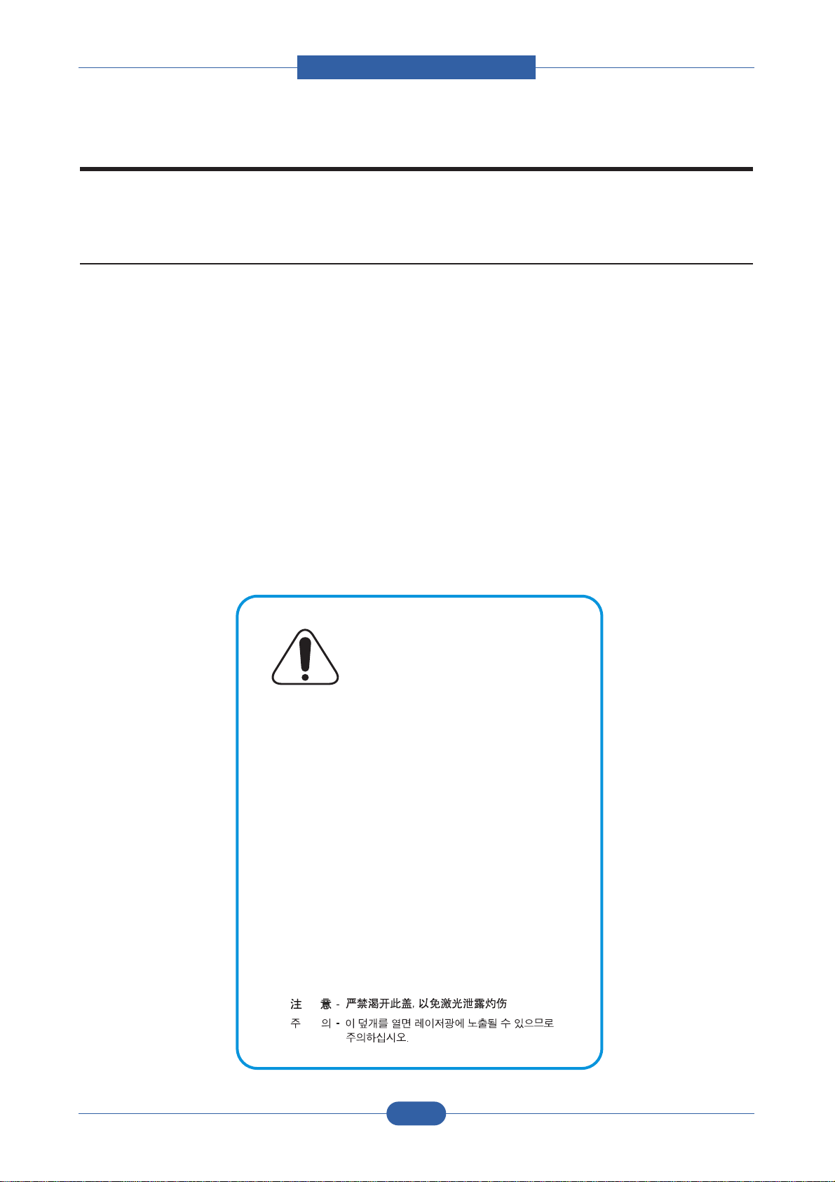
In order to prevent accidents and to prevent damage to the equipment please read the precautions listed
below carefully before servicing the printer and follow them closely.
CAUTION - INVISIBLE LASER RADIATION
WHEN THIS COVER OPEN.
DO NOT OPEN THIS COVER.
VORSICHT - UNSICHTBARE LASERSTRAHLUNG,
WENN ABDECKUNG GEÖFFNET.
NICHT DEM STRAHL AUSSETZEN.
ATTENTION - RAYONNEMENT LASER INVISIBLE EN CAS
D’OUVERTURE. EXPOSITION DANGEREUSE
AU FAISCEAU.
ATTENZIONE - RADIAZIONE LASER INVISIBILE IN CASO DI
APERTURA. EVITARE L’ESPOSIZIONE AL
FASCIO.
PRECAUCION - RADIACION LASER IVISIBLE CUANDO SE ABRE.
EVITAR EXPONERSE AL RAYO.
ADVARSEL. - USYNLIG LASERSTRÅLNING VED ÅBNING, NÅR
SIKKERHEDSBRYDERE ER UDE AF FUNKTION.
UNDGÅ UDSAETTELSE FOR STRÅLNING.
ADVARSEL. - USYNLIG LASERSTRÅLNING NÅR DEKSEL
ÅPNES. STIRR IKKE INN I STRÅLEN.
UNNGÅ EKSPONERING FOR STRÅLEN.
VARNING - OSYNLIG LASERSTRÅLNING NÄR DENNA DEL
ÄR ÖPPNAD OCH SPÄRREN ÄR URKOPPLAD.
BETRAKTA EJ STRÅLEN. STRÅLEN ÄR FARLIG.
VARO! - AVATTAESSA JA SUOJALUKITUS OHITETTAESSA
OLET ALTTIINA NÄKYMÄTTÖMÄLLE LASER-
SÄTEILYLLE ÄLÄ KATSO SÄTEESEEN.
1.1 Safety Warning
(1) Only to be serviced by appropriately qualified service engineers.
High voltages and lasers inside this product are dangerous. This printer should only be serviced by a suitably
trained and qualified service engineer.
(2) Use only authorized replacement parts
There are no user serviceable parts inside the printer. Do not make any unauthorized changes or
additions to the printer, these could cause the printer to malfunction and create electric shock or fire haz-ards.
(3) Laser Safety Statement
The Printer is certified in the U.S. to conform to the requirements of DHHS 21 CFR, chapter 1 Subchapter J for
Class 1(1) laser products, and elsewhere, it is certified as a Class I laser product
con-forming to the requirements of IEC 825. Class I laser products are not considered to be hazardous. The
laser system and printer are designed so there is never any human access to laser radiation above a Class I
level during normal operation, user maintenance, or prescribed service condition.
Warning >> Never operate or service the printer with the protective cover removed from Laser/Scanner assembly. The
reflected beam, although invisible, can damage your eyes. When using this product, these basic safety
pre-cautions should always be followed to reduce risk of fire, electric shock, and injury to persons.
1-1
Page 8

Service Manual
Precautions
1.2 Caution for safety
1.2.1 Toxic material
This product contains toxic materials that could cause illness if ingested.
(1) If the LCD control panel is damaged it is possible for the liquid inside to leak. This liquid is toxic. Contact with the skin
should be avoided, wash any splashes from eyes or skin immediately and contact your doctor. If the liquid gets into
the mouth or is swallowed see a doctor immediately.
(2) Please keep toner cartridges away from children. The toner powder contained in the toner cartridge may be harmful
and if swallowed you should contact a doctor.
1.2.2 Electric Shock and Fire Safety Precautions
Failure to follow the following instructions could cause electric shock or potentially cause a fire.
(1) Use only the correct voltage, failure to do so could damage the printer and potentially cause a fire cause an
electric shock.
(2) Use only the power cable supplied with the printer. Use of an incorrectly specified cable could cause the cable
to overheat and potentially cause a fire.
(3) Do not overload the power socket, this could lead to overheating of the cables inside the wall and could lead to
a fire.
(4) Do not allow water or other liquids to spill into the printer, this can cause electric shock. Do not allow paper
clips, pins or other foreign objects to fall into the printer these could cause a short circuit leading to an electric
shock or fire hazard..
(5) Never touch the plugs on either end of the power cable with wet hands, this can cause electric shock. When
servicing the printer remove the power plug from the wall socket.
(6) Use caution when inserting or taking off the power plug. The power plug has to be inserted completely. If not,
a fire will be caused due to poor contact. When taking off the power plug, grip the plug and remove it.
(7) Take care of the power cable. Do not allow it to become twisted, bent sharply round corners or other wise
damaged. Do not place objects on top of the power cable. If the power cable is damaged it could overheat and
cause a fire or exposed cables could cause an electric shock. Replace a damaged power cable immediately,
do not reuse or repair the damaged cable. Some chemicals can attack the coating on the power cable,
weakening the cover or exposing cables causing fire and shock risks.
(8) Ensure that the power sockets and plugs are not cracked or broken in any way. Any such defects should be
repaired immediately. Take care not to cut or damage the power cable or plugs when moving the machine.
(9) Use caution during thunder or lightening storms. It is recommend that this machine be disconnected from
the power source when such weather conditions are expected. Do not touch the machine or the power cord if it
is still connected to the wall socket in these weather conditions.
(10) Avoid damp or dusty areas, install the printer in a clean well ventilated location. Do not position the machine
near a humidifier. Damp and dust build up inside the machine can lead to overheating and cause a fire.
(11) Do not position the printer in direct sunlight. This will cause the temperature inside the printer to rise possibly
leading to the printer failing to work properly and in extreme conditions could lead to a fire.
(12) Do not insert any metal objects into the machine through the ventilator fan or other part of the casing, it could
make contact with a high voltage conductor inside the machine and cause an electric shock.
1-2
Page 9

Service Manual
Precautions
1.2.3 Handling Precautions
The following instructions are for your own personal safety, to avoid injury and so as not to damage the printer
(1) Ensure the printer is installed on a level surface, capable of supporting its weight. Failure to do so could cause
the printer to tip or fall.
(2) printer contains many rollers, gears and fans. Take great care to ensure that you do not catch your fingers, hair
or clothing in any of these rotating devices.
(3) Do not place any small metal objects, containers of water, chemicals or other liquids close to the printer which if
spilled could get into the machine and cause damage or a shock or fire hazard.
(4) Do not install the machine in areas with high dust or moisture levels, beside on open window or close to a
humidifier or heater. Damage could be cause to the printer in such areas.
(5) Do not place candles, burning cigarettes, etc on the printer, These could cause a fire.
1.2.4 Assembly / Disassembly Precautions
Replace parts carefully, always use authorized parts. Take care to note the exact location of parts and also
cable routing before dismantling any part of the machine. Ensure all parts and cables are replaced correctly.
Please carry out the following procedures before dismantling the printer or replacing any parts.
(1) Check the contents of the machine memory and make a note of any user settings. These will be erased if the
mainboard or network card is replaced.
(2) Ensure that power is disconnected before servicing or replacing any electrical parts.
(3) Disconnect printer interface cables and power cables.
(4) Only use approved spare parts. Ensure that part number, product name, any voltage, current or temperature
rating are correct.
(5) When removing or re-fitting any parts do not use excessive force, especially when fitting screws into plastic.
(6) Take care not to drop any small parts into the machine.
(7) Handling of the Toner Cartridge
- The OPC Drum can be irreparably damaged if it exposed to light.
Take care not to expose the OPC Drum either to direct sunlight or to fluorescent or incandescent room
lighting. Exposure for as little as 5 mins can damage the surface’s photoconductive properties and will result
in print quality degradation. Take extra care when servicing the printer. Remove the OPC Drum and store it in
a black bag or other lightproof container. Take care when working with the covers(especially the top cover)
open as light is admitted to the OPC area and can damage the OPC Drum.
- Take care not to scratch the green surface of OPC Drum Unit.
If the green surface of the Drum Cartridge is scratched or touched the print quality will be compromised.
1-3
Page 10
Service Manual
Precautions
1.2.5 Disregarding this warning may cause bodily injury
(1) Be careful with the high temperature part.
The fuser unit works at a high temperature. Use caution when working on the printer. Wait for the fuser to cool
down before disassembly.
(2) Do not put finger or hair into the rotating parts.
Take care when using a printer. It contains many rotating parts. Ensure that fingers, hair, clothing etc. do not
become caught in the mechanism as this could cause injury.
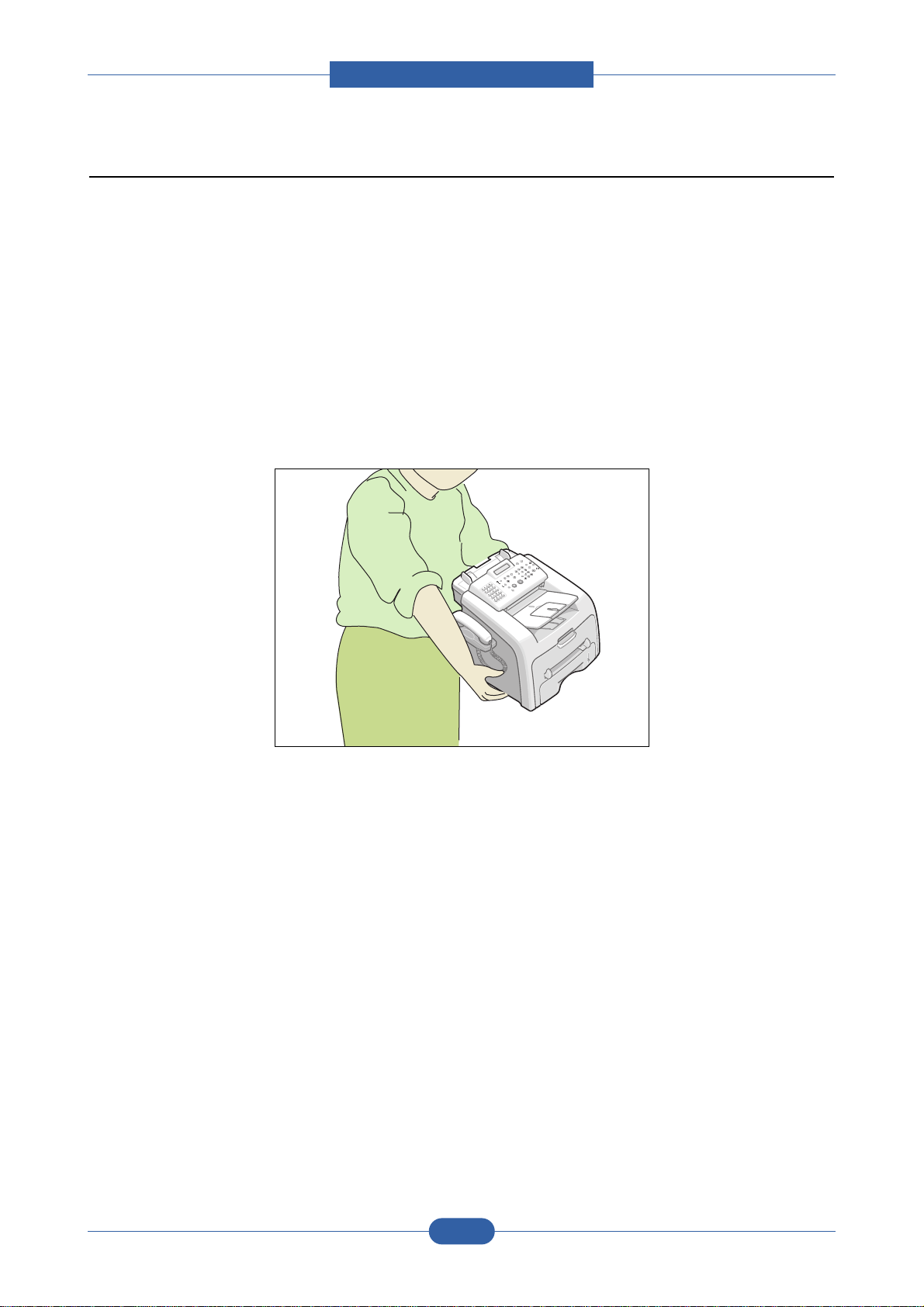
(3) When you move the printer.
This printer weighs 10kg including toner cartridge and cassette. Use safe lifting and handling techniques. Use
the lifting handles located on each side of the machine. Back injury could be caused if you do not lift carefully.
(4) Ensure the printer is installed safely.
The printer weighs 10Kg, ensure the printer is installed on a level surface, capable of supporting its weight.
Failure to do so could cause the printer to tip or fall possibly causing personal injury or damaging the printer.
(5) Do not install the printer on a sloping or unstable surface. After installation, double check that the printer is
stable.
1-4
Page 11

Service Manual
Precautions
1.3 ESD Precautions
Certain semiconductor devices can be easily damaged by static electricity. Such components are commonly called
“Electrostatically Sensitive (ES) Devices”, or ESDs. Examples of typical ESDs are: integrated circuits, some field
effect transistors, and semiconductor “chip” components.
The techniques outlined below should be followed to help reduce the incidence of component damage caused by
static electricity.
Caution >>Be sure no power is applied to the chassis or circuit, and observe all other safety precautions.
1. Immediately before handling a semiconductor component or semiconductor-equipped assembly, drain off any
electrostatic charge on your body by touching a known earth ground. Alternatively, employ a commercially available wrist strap device, which should be removed for your personal safety reasons prior to applying power to the
unit under test.
2. After removing an electrical assembly equipped with ESDs, place the assembly on a conductive surface, such as
aluminum or copper foil, or conductive foam, to prevent electrostatic charge buildup in the vicinity of the assembly.
3. Use only a grounded tip soldering iron to solder or desolder ESDs.
4. Use only an “anti-static” solder removal device. Some solder removal devices not classified as “anti-static” can
generate electrical charges sufficient to damage ESDs.
5. Do not use Freon-propelled chemicals. When sprayed, these can generate electrical charges sufficient to damage ESDs.
6. Do not remove a replacement ESD from its protective packaging until immediately before installing it. Most
replacement ESDs are packaged with all leads shorted together by conductive foam, aluminum foil, or a comparable conductive material.
7. Immediately before removing the protective shorting material from the leads of a replacement ESD, touch the protective material to the chassis or circuit assembly into which the device will be installed.
8. Maintain continuous electrical contact between the ESD and the assembly into which it will be installed, until completely plugged or soldered into the circuit.
9. Minimize bodily motions when handling unpackaged replacement ESDs. Normal motions, such as the brushing
together of clothing fabric and lifting one’s foot from a carpeted floor, can generate static electricity sufficient to
damage an ESD.
1-5
Page 12

Page 13

Service Manual
Product spec and feature
2. Product specification and feature
2.1 Product Specifications
Specfications are correct at the time of printing. Product specifications are subject to change without notice.
See below for product specifications.
Model Name F-114P F-114
Functions Fax,Copier,Printer,Scanner Fax,Copier
General Size (W*D*H) w/o Hand Set 363.0 * 398.0 * 308.3(mm) 363.0 * 398.0 * 308.3(mm)
Power Power Switch Yes Yes
Consumption Input Voltage
**Noise Operating(ADF) Less than 52 dBA Less than 52 dBA
EMI Approval EMI Approval Class B Class B
PC Print Power Save Mode Yes (5/10/15/30/45min.off) Yes (5/10/15/30/45min.off)
Items F-114 Series
Weight Without Toner Cartridge 10kg 10kg
With Toner Cartridge 11.5kg 11.5kg
LCD 16*2 16*2
Interface USB 1.1 USB 1.1 : f/w Down Load
AMV(Average Month Volume)
Duty cycle, Monthly Printing Up to 10,000 pages Up to 10,000 pages
Engine Life Up to 120,000 Pages Up to 120,000 Pages
Power Sleep Mode Energy Star Compliant Energy Star Compliant
Standby Less than 39 dBA Less than 39 dBA
Printing Less than 509 dBA Less than 50 dBA
Print Method Laser Laser
N/W I/f No No
* Speed (Engine) Up to 16 PPM in A4 size, -
Resolution Normal
Print Language GDI Toner Save Yes Yes(Text Mode)
Fpot Stand by Approx. 12 seconds -
Printable Area 208 x 273 mm (Letter) Duplex Print
Printing 500 Scan to Copy
or Scan to Fax
ADF SCAN Up to 2,000 pages Up to 2,000 pages
RET No -
Power Save Less than 42 seconds -
500 500
AC110V~127V, 220V ~ 240V AC110V~127V, 220V ~ 240V
(Fax Rec., Memory Copy)
Up to 17 PPM in Letter size
Up to 600 x 600 DPI effective output
Manual (driver support provided)
-
-
* Speed will be affected by Operating System used, computing performance, application software, connect-
ing method, media type, media size and job complexity.
** Sound Pressure Level, ISO 7779
2-1
Page 14

Service Manual
Product spec and feature
Items F-114 Series
Model Name F-114P F-114
Scan Halftone 256level 256level
Scan Method "CIS, Mono" "CIS, Mono"
*Scan Speed Gray Up to 72 sec (Second /scan) Color - -
Black&White Up to 25 sec -
Resolution(Optical)
Up to 200 x 200 DPI effective output Up to 200 x 200 DPI effective output
Halftone 256level Scan Width Max 216mm -
Effective 208mm -
Scan Length Max 400mm -
Copy Speed Up to 16 PPM in A4 size, Up to 16 PPM in A4 size,
Up to 17 PPM in Letter size Up to 17 PPM in Letter size
Resolution
Up to 300 x 300 DPI effective output Up to 300 x 300 DPI effective output
Halftone 256level 256level
Copy Quality Selection Text 16sec/Letter 16sec/Letter
or Original Image type Photo 16sec/letter 16sec/letter
selection Mode
FCOT Power Save Yes Yes
Stand by approx : 30sec approx : 30sec
*Copy Speed SDMC Up to 16 PPM in A4 size, Up to 16 PPM in A4 size,
Up to 17 PPM in Letter size Up to 17 PPM in Letter size
MDMC 3cpm 3cpm
Zoom Range 50-150% 50-150%
Multi Copy 1~99 1~99
Telephone Handset Yes Yes
1-Touch Dial 20 20
Speed Dial 80 80
TAD No No
TAD I/F Yes Yes
Tone/Pulse Tone (DTMF) Tone (DTMF)
Pulse : setting in tech mode Pulse : setting in tech mode
Earth/Recall No No
SMS No No
External Phone Interface Yes Yes
Fax Compatibility ITU-T G3 ITU-T G3
Communication System PSTN/PABX PSTN/PABX
Modem Speed 33.6Kbps 33.6Kbps
TX Speed approx. 3 sec approx. 3 sec
Compression MH/MR/MMR MH/MR/MMR
ECM Yes Yes
Resolution Std
Fine
S.Fine
Up to 203 x 98 DPI effective output Up to 203 x 98 DPI effective output
Up to 203 x 196 DPI effective output Up to 203 x 196 DPI effective output
Up to 203 x 392 DPI effective output Up to 203 x 392 DPI effective output
Std Up to 6 sec Up to 6 sec
Fine Up to 12 sec Up to 12 sec
S.Fine Up to 24 sec Up to 24 sec
2-2
Page 15

Service Manual
Product spec and feature
* Copy or Scan speed will be affected by Operating System used, computing performance, application software,
connecting method, media type, media size and job complexity.
Items F-114 Series
Model Name F-114P F-114
Fax Halftone 256level 256level
(Continued) Memory Capacity
Optional Memory
Total memory: 8MB( Fax: 2MB) Total memory: 8MB(Fax: 2MB)
No No
Broadcasting Yes Yes
Delay TX Yes Yes
Memory RX Yes Yes
Functions Voice Request No No
TTI Yes Yes
RTI Yes Yes
Polling Rx Polling Rx Polling
Security Receive Yes Yes
Flash No No
Auto Reduction Yes Yes
"F/W Upgrade Yes Yes
from Remote"
Memory B/U Yes(96 Hour) Yes(96 Hour)
Paper Handling
Casstte Type Cassette Cassette
Input Capacity 250Sheets/20lb 250Sheets/20lb
Optional Cassette
Output Capacity
No No
Max. 150 sheets/20lb Max 150 sheets/20lb
Output Control Face down Face down
Bypass 1sh 1sh
Media Size for For Fax and Copy: A4,Letter, For Fax and Copy: A4,Letter,
Main Tray Legal For PC Print : A4,Letter, Legal For PC Print : A4,Letter,
Legal. Folio, Executive, B5 Legal. Folio, Executive, B5"
Media Size for Envelope6 3/4, 7 3/4,#9, Envelope6 3/4, 7 3/4,#9,
Bypass #10,DL,C5,B5 #10,DL,C5,B5
Media Weight Auto : 16 ~ 28 Ib Auto : 16 ~ 28 Ib
Bypass: 16 ~ 43 Ib Bypass: 16 ~ 43 Ib
ADF Input Capacity Min. 20 Sheets Min. 20 Sheets
Media Weight 12.5lb ~ 28lb, 32lb(1 sheet) 12.5lb ~ 28lb, 32lb(1 sheet)
2-3
Page 16

Service Manual
Product spec and feature
Items F-114 Series
Model Name F-114P F-114
Software Windows Win 2000 Yes No
Compatiblity Win 2003 Yes No
(Scan/Print) Win XP Yes No
Win Vista Yes No
Driver GDI Printer SPL No
TWAIN Yes No
FaxRCP Yes No
(Windows ONLY)
Mac Printer Yes No
Mac Scanner No No
Linux Printer Yes No
Linux Scanner Yes No
PC-FAX No No
M/S Certification WHQL Yes (Win 2000/2003/XP) -
WIA No No
Bundle S/W SmarThru 3 Media CD-ROM Yes -
Manual Standalone Fax: Book Standalone Fax: Book
MFP: CD
Diskette No No
Consumables Life Initial 1,000 Pages 1,000 Pages
Running 3,000 Pages 3,000 Pages
Toner Sensor (Software) Yes(Dot Counter) Yes(Dot Counter)
Periodic Replacing Parts Pick Up Roller : Up to 60,000 sheets
Transfer Roller : Up to 60,000 sheets
Fuser Assembly : Up to 60,000 sheets
ADF Roller : Up to 60,000 sheets
ADF Rubber : Up to 10,000 sheets
2-4
Page 17
Product spec and feature
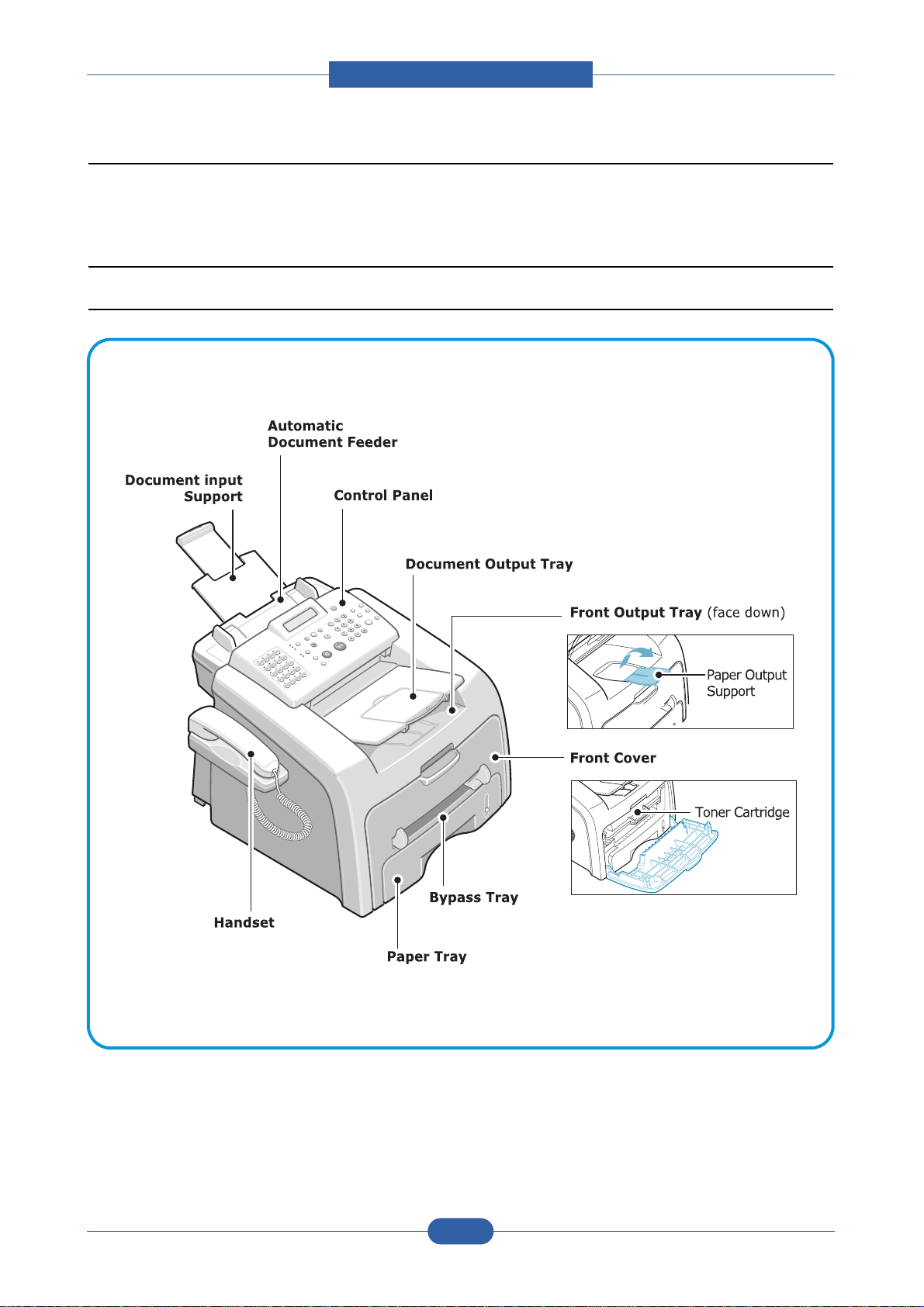
2.2 Summary of Product
This chapter describes the functions and operating principals of the main components.
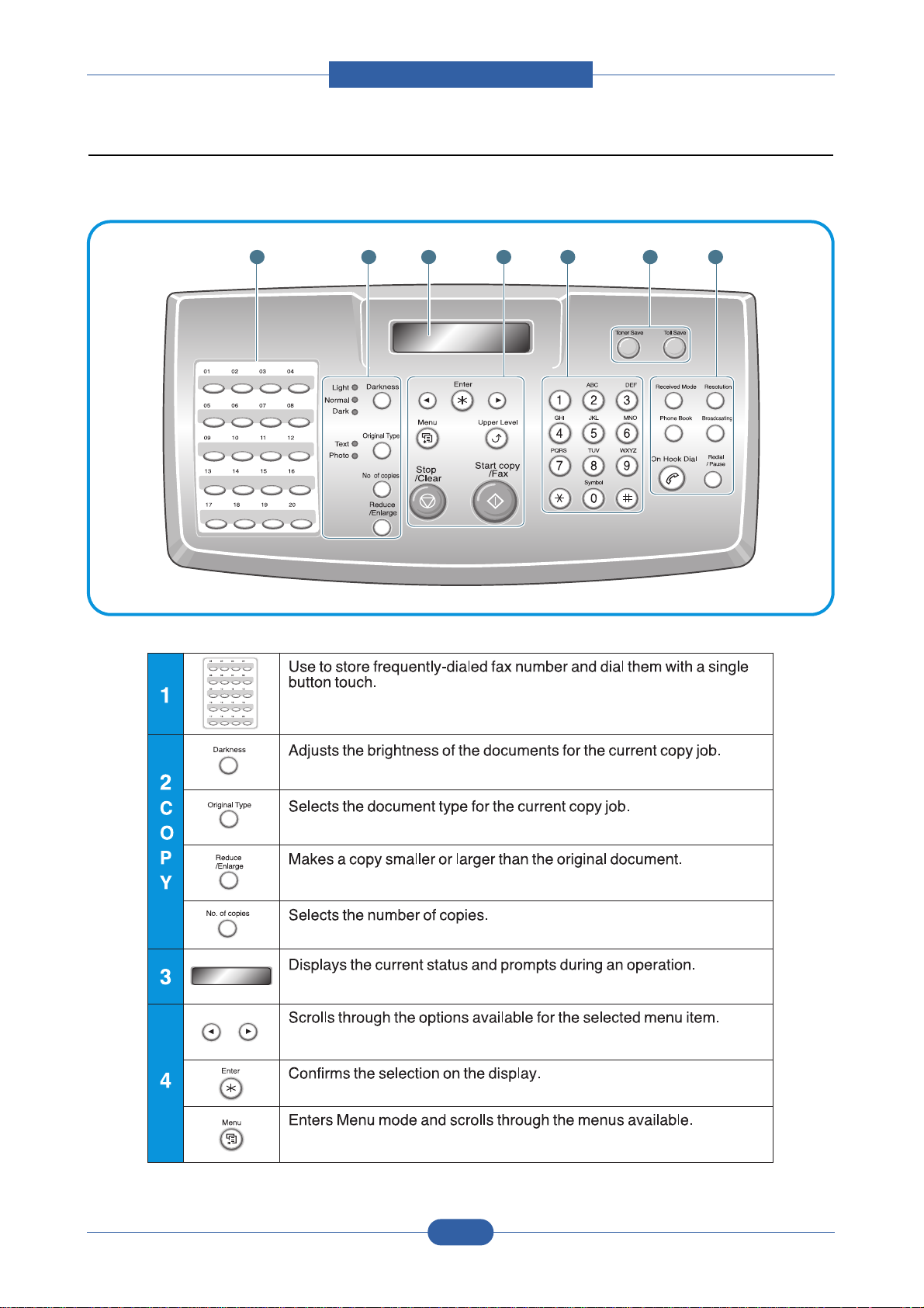
2.2.1 Printer Components
2.2.1.1 Front View
Summary of Product
Service Manual
2-5
Page 18

Service Manual
Product spec and feature
Items F-114 Series
Model Name F-114P F-114
Software Windows Win 2000 Yes No
Compatiblity Win 2003 Yes No
(Scan/Print) Win XP Yes No
Win Vista Yes No
Driver GDI Printer SPL No
TWAIN Yes No
FaxRCP Yes No
(Windows ONLY)
Mac Printer Yes No
Mac Scanner No No
Linux Printer Yes No
Linux Scanner Yes No
PC-FAX No No
M/S Certification WHQL Yes (Win 2000/2003/XP) -
WIA No No
Bundle S/W SmarThru 3 Media CD-ROM Yes -
Manual Standalone Fax: Book Standalone Fax: Book
MFP: CD
Diskette No No
Consumables Life Initial 1,000 Pages 1,000 Pages
Running 3,000 Pages 3,000 Pages
Toner Sensor (Software) Yes(Dot Counter) Yes(Dot Counter)
Periodic Replacing Parts Pick Up Roller : Up to 60,000 sheets
Transfer Roller : Up to 60,000 sheets
Fuser Assembly : Up to 60,000 sheets
ADF Roller : Up to 60,000 sheets
ADF Rubber : Up to 10,000 sheets
2-4
Page 19
Service Manual
Product spec and feature
1 2 43 5 6 7
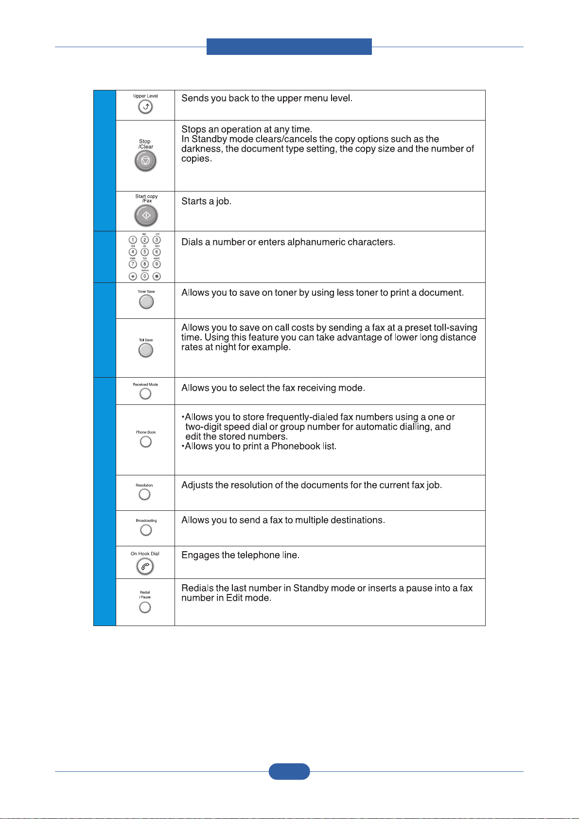
2.2.1.3 Control Panel
< F-114 / F-114P >
2-7
Page 20
Service Manual
Product spec and feature
4
5
6
S
A
V
E
7
F
A
X
2-8
Page 21

Service Manual
Product spec and feature
2.2.2.2 Line Interface.
This part connects the set with the PSTN. The main functions of this section are Line Interface, Line Monitoring,
and connection to an external phone or TAD using the built in EXT connector..
2.2.2.3 Print Engine.
The Print Engine consists of the following sections: Frame, Paper Feed, Image Transfer, Imaging Unit, Toner
Cartridge, Fuser, High Voltage Supply and Scanner. The set uses an Electro Photographic process using the LSU
to develop a latent image on the OPC drum. The Toner process is a single part diamagnetic process. Copy and
Transfer processes use a CIS Module.
2.2.2.5 Summary of Main Unit
- Main Board
This is an integral unit having the Engine and Video control on a single PBA. It controls the Electrophotographic
Process to take the image from the PC Interface and generate the Video Data for the LSU. It also manages the
transfer of that image onto paper and the fusing of the image. The main PBA unit consists of the following circuits:
Motor (Paper Feed and Exit) Driver, the Clutch driver, Pre-transfer Lamp Driver, the Fuser Driver and the Fan
Driver. The signals from the Paper Feed Sensor, the Paper Empty Sensor, MP sensor and Exit Sensor are input to
the Main Board from the SMPS/HVPS PBA.
2.2.2 Overview of System
The F-114 / F-114P can be divided into the following main constituent parts: Main Controller, Operator’s Panel,
PC Interface, Scanner, Line Interface and Power Supply. The Main Controller uses an SPGPm processor. The
Operator’s panel; (OPE) has its own MICOM which communicates serially with a UART built into the SPGPm
processor. The Scanner uses an Image Processor chip (CIP4) to control the CIS. The Line Interface an FM336
integrated with the Main Board and communicates with the LIU at speeds up to 33.6Kbps. The Power Supply has
both the SMPS and HVPS integrated on one PBA.
2.2.2.1 Main Controller.
The Main Controller of the F-114 / F-114P consists of two ASICs (CPU, Image Processor), Scanner, Fax Modem
and Print sections. Bus Control, I/O Handling, Scanner, all motor drivers and the PC Interface function is controlled
by the CPU.
It uses the chorus2. These control the peripherals and the Image Processing.
2.2.2.4 Scanner.
The scanner is designed around a 200dpi CIS module. The CIS scanning width is maximum 216mm,
effective width is 208mm. The F-114 operates at 200lpi, the F-114P operates at 300 lpi.
2-9
Page 22

Product spec and feature
- SMPS Board & HVPS Board
These are integrated into a singe PBA. The Power Supply uses the 110VAC/220VAC supply voltage to
generate the DC Voltages used by the system. The SMPS has 3 output channels (+5V, +12V, +24V, +24VS) and
supplies the Main Board and the OPE Board.
The HVPS creates the high voltages (THV/MHV/Supply/Dev) used for the electrophotographic process. The high
voltage is created from the 24VS line from the SMPS. High Voltage output is supplied to the Toner, the OPC
Cartridge and the Transfer Roller.
- OPE Board
The Operation Panel is driven by its own internal program using the OPE MICOM chip separate from the Main
Board processor. Data is transferred using the UART Port in the Main Controller serially. This unit
consists of the MICOM, the Key Pad Matrix and the LCD.
- Toner Cartridge
The Toner Cartridge consists of integrated Exposure and Developer units. The Exposure Unit consists of the OPC
Drum and the Charge Roller, and the Developer Unit consists of the toner particles and its tank, the Supply Roller
and the Developer Roller.
- LSU (Laser Scanner Unit)
This is the core of the laser printer. It converts the video data received from the computer into an electrostatic
latent image on the surface of the OPC drum. This is achieved by controlling the laser beam and exposing the surface of the OPC drum to the laser light. A rotating polygon mirror reflects the laser light onto the OPC and each
side of the mirror is one scan line. The OPC drum turns as the paper feeds to scan the image down the page.
The /HSYNC signal is created when the laser beam from LSU reaches the end of the polygon mirror and this signal is sent to the controller. The controller detects the /HSYNC signal to adjust the vertical line of the image on
paper. In other words after the /HSYNC signal is detected the image data is sent to the LSU to adjust the left margin on the paper.
- Toner Transfer
Toner is transferred from the OPC drum onto the paper using a PTL (Pre-transfer Lamp) and a transfer roller. The
PTL shines light onto the OPC, this reduces the electrical charge on the surface of the OPC
surface and improves the efficiency of the transfer.
The transfer roller transfers toner from the OPC drum to the paper.
Life span: Print over 100,000 sheets (at 15~30ºC)
- Fuser
This consists of a heat lamp, heat roller, pressure roller, thermistor and thermostat. By use of heat and pressure
toner is caused to melt and adhere to the paper surface in order to complete the printing process.
Service Manual
2-10
Page 23

Service Manual
Product spec and feature
2.2.3 System Layout
2.2.3.1 Feeding section
There is a universal cassette which automatically loads paper and the manual feed which supplies paper
single sheet at a time. The cassette has a friction pad which separates paper to ensure single sheet
feeding, and it has a sensor, which checks when the paper tray is empty.
- Feeding Method: Universal Cassette Type
- Feeding Standard: Center Loading
- Feeding Capacity: Cassette-250 sheets (75g/m
2
, 20lb paper standard)
Manual 1 sheet (Paper, OHP, Envelop, etc.)
- Paper detecting sensor: Photo sensor
- Paper size sensor: None
2.2.3.2 Transfer Ass’y
This consists of the PTL (pre-transfer lamp) and the Transfer Roller. The PTL shines a light onto the OPC
drum. This lowers the charge on the drum’s surface and improves transfer efficiency.
The transfer roller transfers toner from the OPC drum surface to the paper.
- Life expectancy: Over 60,000 sheets (at 15~30°C)
2.2.3.3 Driver Ass’y
- Gear driven power unit. The motor supplies power to the paper feed unit, the fuser unit, and the toner
cartridge.
2.2.3.4 Fixing Part(Fuser)
- The fuser consists of the Heat Lamp, Heat Roller, Pressure Roller, Thermistor, and Thermostat. It fixes
toner to the paper using pressure and heat to complete the printing job.
2.2.3.4(a) Temperature-Intercepting Device (Thermostat)
The thermostat is a temperature sensing device, which cuts off the power to the heat lamp to prevent
overheating fire when the heat lamp or heat roller overheats.
2.2.3.4(b) Temperature Detecting Sensor (Thermistor)
The Thermistor detects the surface temperature of the heat roller, this information is sent to the main
processor which uses this information to regulate the temperature of the heat roller.
2.2.3.4(c) Heat Roller
The surface of the Heat Roller is heated by the Heat Lamp. As the paper passes between the Heat and
Pressure rollers the toner is melted and fixed permanently to the paper. The surface of the roller is coated
with Teflon. This ensures that toner does not adhere to the roller surface.
2.2.3.4(d) Pressure roller
The Pressure Roller mounted under the heat roller, it is made of a silicon resin, and the surface of the roller
is coated with Teflon. This ensures that toner does not adhere to the roller surface.
2-11
Page 24

Product spec and feature
2.2.3.4(e) Safety Features
• To prevent overheating
- 1st protection device: Hardware cuts off when overheated
- 2nd protection device: Software cuts off when overheated
- 3rd protection device: Thermostat cuts off mains power to the lamp.
• Safety device
- Fuser power is cut off when the front cover is opened
- LSU power is cut off when the front cover is opened
- The temperature of the fuser cover's surface is maintained at less than 80ºC to protect the user and a
caution label is attached where the customer can see it easily when the rear cover is opened.
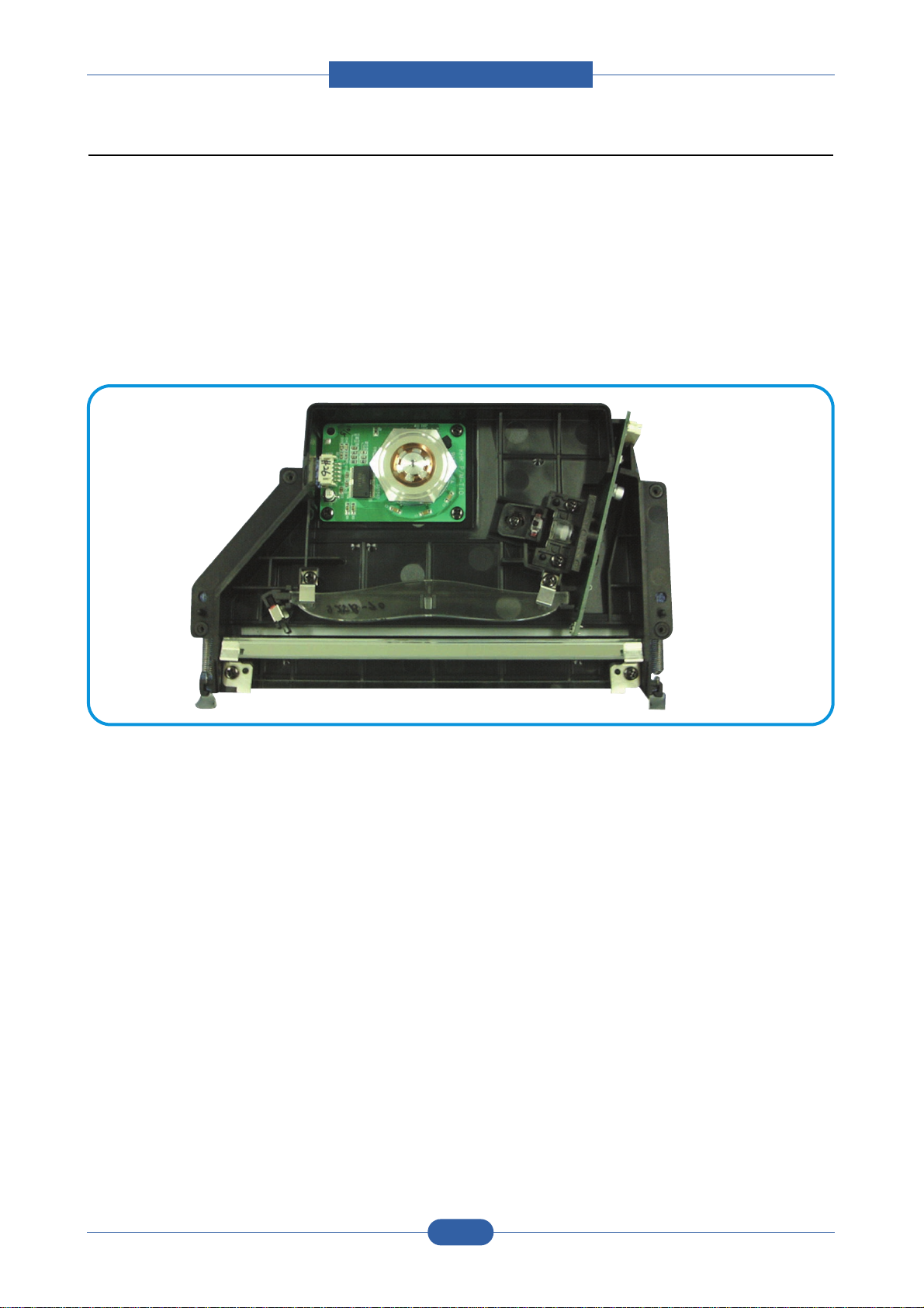
2.2.3.5 Scanner
• Scan Image Controller
1.Minimum Scan Line Time : 1.23ms
2.Scan Resolution : Color (Max 600 DPI)
3.Scan Width : 208mm
4.Function
- White Shading Correction
- Gamma Correction
- CIS Interface
- 256 Gray Scale
• CIS Driver Circuit
- CIS Max Frequency : 0.5MHz
- CIS Line Time : 5ms
- White Data Output Voltage : Max 1.2V
• Tx Driver Circuit
- Tx Motor Speed : Max 2200pps
- Motor Driver : STA471A
- Voltage : 24V DC
Service Manual
2-12
Page 25
Service Manual
Product spec and feature
2.2.3.6 LSU (Laser Scanner Unit)
This is the core of the laser printer. It converts the video data received from the computer into an electrostatic latent image on the surface of the OPC drum. This is achieved by controlling the laser beam and exposing the surface of the OPC drum to the laser light. A rotating polygon mirror reflects the laser light onto the
OPC and each side of the mirror is one scan line. The OPC drum turns as the paper feeds to scan the
image down the page.
The /HSYNC signal is created when the laser beam from LSU reaches the end of the polygon mirror and
this signal is sent to the controller. The controller detects the /HSYNC signal to adjust the vertical line of the
image on paper. In other words after the /HSYNC signal is detected the image data is sent to the LSU to
adjust the left margin on the paper.
2-13
Page 26

Service Manual
Product spec and feature
2.2.3.7 Toner Cartridge
The toner cartridge is an integral unit containing the OPC unit and toner unit. The OPC unit consists of the
OPC drum and charging roller, and the toner cartridge unit consists of the toner, supply roller, developing
roller, and blade (Doctor blade)
- Developing Method: Non magnetic 1 element contacting method
- Toner: Non magnetic 1 element shatter type toner
- The life span of toner: 3,000 sheets (IDC Pattern/A4 standard)
- Toner remaining amount detecting sensor: Yes
- OPC Cleaning: Electrostatic process
- Management of waste toner: Collect the toner using a Cleaning Blade
- OPC Drum protecting Shutter: Yes
- Classifying device for toner cartridge: ID is classified by interruption of the frame channel
2-14
Page 27
Service Manual
Product spec and feature
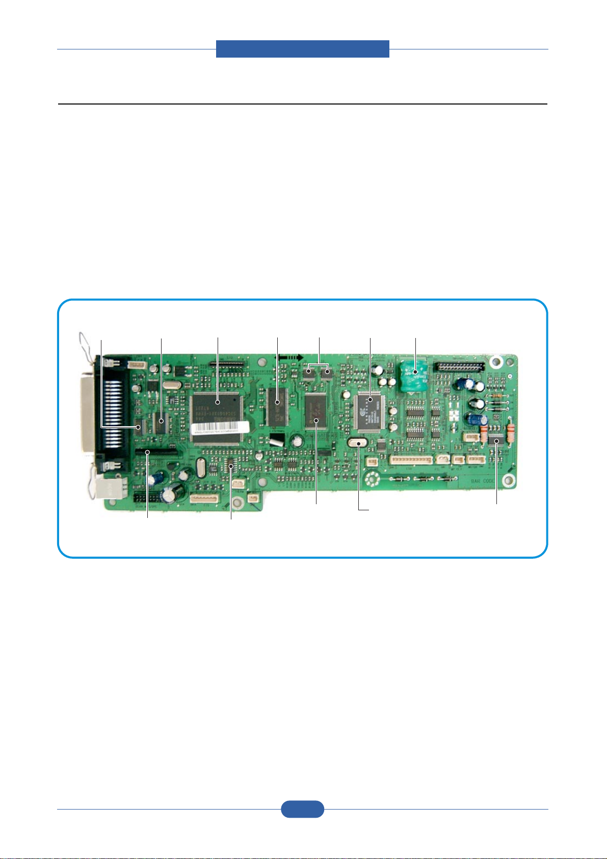
FLASH
MEMORY
MODEM
EXPANSION I/O
(HCT273)
Battery
SDRAM
STA471
(SCAN MOTOR DRIVE I/C)
SUPER1284
BUFFER(INVERTER)
74HCTO 4M
MODEM CLOCK
MOTOR DIRVE IC
(A3 977 SLP)
ASIC
74LVX161284
2.2.4 Main PBA(SPL Model)
The Engine Board and Controller Board have been integrated into a single PBA. This consists of the CPU,
printer scanner and line control functions. The CPU functions as the bus controller, I/O handler, motor driver
and PC inter-face. The main board sends the Current Image Video data to the LSU and manages the
Electrophotographic printing process. Circuits on the PBA drive include the main motor (paper feed,
cartridge, fuser), clutch driver, pre-transfer lamp driver, heat-lamp driver, CIS driver, scan motor driver,
modem and fan driver.
The signals from the paper feed jam sensor and paper empty sensor are inputted to the main board from
the power supply PBA.
Line interface circuit, it is a circuit for interfacing a telephone line with a modem and DAA. The circuit consists of
a matching circuit to conform to the impedance of the receiving telephone line and a circuit to conform to the impedance
of a modem.
Also, there is a ring detect circuit to detect a ring signal from the switchboard and a surge absorber to protect against
lighting strike surges on the incoming line.
2-15
Page 28

Service Manual
Product spec and feature
2.2.4.2 Flash Memory
This stores the system program. Firmware upgrade is achieved by downloading from the new image using the PC
Interface.
• Capacity : 0.5 M Byte
• Access Time : 70 nsec
2.2.4.3 SDRAM
This is used as a buffer, system working memory area, etc. while printing and scanning. This memory is also used to
store faxes waiting to be sent or waiting to be printed.
• Access Time : 60 nsec
2.2.4.1 ASIC (Chorus2)
The unt's S3C46Q0X 16/32-bit RISC micro controller is designed to provide a cost-effective, low power,
small die size and high performance micro-controller solution for MFP.
The S3C46Q0X is developed using ARM7TDMI core, 0.18(m CMOS standard cell, and memory cell.
•Main function block
• 1.8V internal, 3.3V external (I/O boundary) microprocessor with 4KByte Cache
• Image Processor
• On-chip clock generator with PLL
• Memory & External Bank Control
• DMA Control (5-channel)
• Interrupt Control
• 2-port USB Host /1- port USB Device (ver 1.1) Interface Control
• UART (2 Channel)
• Synchronous Serial Interface Control
• Timer (4 Channel)
• Watch Dog Timer
• Power control: Normal, Slow, Idle, Stop and SL_IDLE mode
• A/D Converter (10-bit, 2 Channel)
• General I/O Port Control
• Print Head Control
• Carrier Motor Control
• Paper Motor Control
• Tone Generator
• RTC with calendar function
• S/W Assistant function( Rotator )
2-16
Page 29

Service Manual
Product spec and feature
2.2.4.4 Sensor input circuit
1) Paper Empty Sensor
The Paper Empty sensor (Photo Interrupter) on the SMPS/HVPS PBA is monitored by the CPU on
signal(nP_EMPTY, CN3-Pin 1). When the cassette is empty the printer displays a message on the LCD
panel.
2) MP Sensing
Presence of paper in the MP tray is detected by operation of the MP Sensor (Photo Interrupter) on the
SMPS/HVPS PBA. The CPU monitors signal(MP_EMPTY, CN3-Pin 13) to recognize paper in the MP,
and paper is fed from MP if there is paper present.
3) Paper Feed Sensor, (Toner Cartridge Sensor)
When paper passes the actuator on the feed sensor, it is detected by the Photo interrupter.
signal(nP_FEED, CN3-Pin 2) monitored by the CPU and this signal starts the process of creating the
image after certain delay time If the feed sensor is not detected within 1 sec. after paper is fed, a paper
Jam0 occurs. (Displayed on the LCD panel).
When a toner cartridge is inserted it also operates the Paper Feed sensor. A message is displayed on the
LCD if no cartridge is detected.
4) Paper Exit Sensor
This detects that paper exits cleanly from the Machine using an exit sensor on the engine board and
actuator on the frame. The monitors signal(P_EXIT, CN3-Pin 26) and detects the on/off time of the exit
sensor and if jam status is detected then JAM2 is displayed the on the LCD panel.
5) Cover Open Senser
The Cover open sensor actuator is located on the front cover and the senor is in the main frame. When the
front cover is opened the +24VS to the DC fan, solenoid, main motor, polygon motor part of LSU, HVPS that
are cut off. The CPU monitors
signal(COVER_OPEN)
to recognize when the cover is opened.
6) DC FAN / SOLENOID Driving
It is driven by a transistor and controlled by signal(FAN, CN3-Pin 24) bit of the CPU.
When it is high the fan is activated by turning on the TR, and it is off when the sleep mode is selected.
There are two solenoids and these are driven by the Paper Pick-up and MP signals. The drive time is
300ms. The diode protects the driving TR from the Back-EMF pulse which is generated when the
solenoid is de-energized.
7) Motor Driving
The motor driving circuit is activated when the Driver IC is enabled. An A3977 (Motor driver IC) is used in
this case. The resistance Rs value of sensing and the voltage value of the V reference can be changed
by the motor driving voltage value.
2-17
Page 30
Service Manual
Product spec and feature
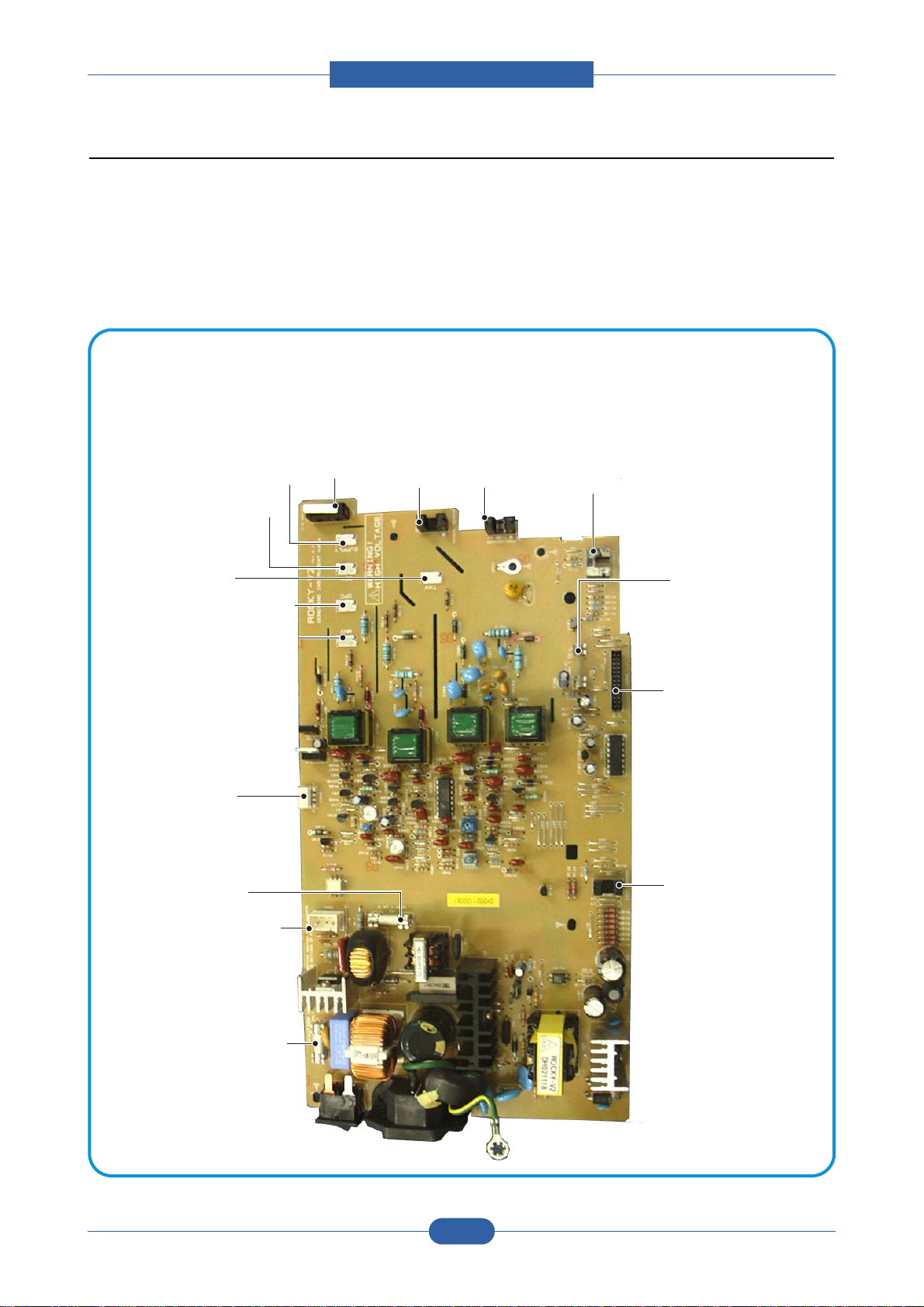
2.2.5 SMPS & HVPS
The SMPS and HVPS are on one integrated board.
The SMPS supplies the DC power to the system. It takes either 110V or 220V and outputs the +5V,
-5V/0.5A, 12V and 24V supplies to the main and ADF PBAs.
The HVPS creates the high voltage of THV/MHV/Supply/Dev and supplies it to the toner cartridge. The CPU is
used to modify some of these voltage settings to provide the ideal voltages to create the image.
The HVPS part uses the 24V and outputs the high voltage for THV/MHV/BIAS and the outputted high voltage is
supplied to the toner, OPC cartridge and transfer roller.
MAIN PBA CON.
CN3
(FAN CON.)
CN1
(H/L CON.)
F101
250V L2A
EXIT SENSOR
MHV
OPC
DEV
SUPPLY
THV
COVER OPEN SWITCH
MANUAL SENSOR
FEED SENSOR
PAPER-EMPTY SENSOR
F1
110V : 125V/8A
220V : 250V T 5A H
F2
110V : 125V/3A
220V : 250V 2A H
2-18
Page 31

Service Manual
Product spec and feature
2.2.5.1 HVPS(High Voltage Power Supply)
1) Transfer High Voltage (THV+)
- Function : It is this voltage that transfers toner from the OPC Drum to the paper.
- Output voltage : +1300V DC±20V
- Error : IF THV (+) is not present, low density printing occurs due to toner on the OPC Drum not being
transferred to the paper. It is possible that waste toner over-flow can occur if this condition persists.
Ghost images may appear which repeat at 76mm intervals.
2) Charge Voltage (MHV)
- Function : It is this voltage that charges the surface of the OPC to -900V ~ -1000V.
- Output voltage : -1550V DC ± 50V
- Error : IF MHV is not present toner then since the OPC drum surface has no charge toner is attracted to
the whole OPC surface. A black page is printed out when this happens.
3)Cleaning Voltage (THV-)
- Function : It removes toner contamination from the rear side of the paper by sending (-) polarity to the
transfer roller forcing toner to transfer back to the to OPC drum.
- Output Voltage : +300V/-150V
- Error : Smudges and toner contamination on the reverse side of the printed page.
4) Developing Voltage (DEV)
- Function: It is this voltage that develops toner with on to the section of the OPC drum surface exposed
by the LSU
(Laser Scanning Unit).
* When printing the exposed voltage on the OPC is -180V, unexposed is -900~-1000V, and the exposing
voltage on the DEV is -430V. Therefore toner with (-) polarity is developed onto an exposed
section of the OPC.
- Output voltage: -430V DC ± 20V
- Error: a) If DEV is GND, print density gets extremely low.
b) When DEV is floating due to poor connection between the frame and cartridge contacts etc.,
print density gets extremely high.
5) Supply Voltage (SUP)
- Function: It is this voltage that supplies toner to the developing roller.
- Output voltage: : -630V DC ± 50V (Use ZENER, DEV Gear)
- Error: a) When SUP is GND print density gets extremely low.
b) If SUP is floating due to poor connection between the frame and cartridge contacts etc. density
gets extremely low such that it is hard to see toner with the eyes
6) OPC Ground ZENER Voltage
- Function: It is this voltage that prevents image contamination under low temperature and low humidity
environment conditions.
- When a set prints without an output voltage, -130V DC ± 15V is maintained on OPC ground. (-103V
ZENER diode is connected to OPC ground)
- Error type:
a) When the ZENER diode is - 0V there is no serious image problem in general environment,
but in low temperature and low humidity environments it is possible that contamination
can occur on the entire image
b) When the ZENER diode is disconnected a blank page is printed out. (It is the same when
a ZENER diode is disconnected from OPC ground.)
2-19
Page 32

Service Manual
Product spec and feature
2.2.5.2 SMPS (Switching Mode Power Supply)
ItThis is the power source for the whole system. It is an independent module so that it is possible to use it for
common use. It is mounted at the bottom of the set.
It consists of the SMPS section, which supplies the DC power to drive the system, and the AC heater control
part, which supplies the power to the fuser. The SMPS has four output channels ((+5V, -5V, +12V, +12Vand
+24Vs).
There are three kinds of power, 120V exclusive (America), 220V exclusive (Europe), and 220V for China
(nations with unstable power supply).
1) AC Input
- Inputting rated voltage : AC 220V ~ 240V AC 100~127V
- Inputting voltage fluctuating range : AC 198V ~ 264V AC 90V ~ 135V
- Rated frequency : 50/60 Hz
- Frequency fluctuating range : 47 ~ 63 Hz
- Inputting Current : Under 4.0Arms/2.0Arms
2) Rated Power Output
3) Consumption Power
4) Length of Power Cord :
1830 ± 50mm
5) Power Switch :
Fitted
NO Item CH1 CH2 CH3 CH4
1 Channel name +5V -5V +24.0V +24.0VS
2 CONNECTOR PIN CON 2 CON2 CON2 CON2
3.3V PIN: 3, 4 -5V PIN : 7 24V PIN: 11, 12 24V PIN: 13, 16
GND PIN: 5, 6 GND PIN: 8 GND : 9, 10 GND : 18
3 Rated outputting voltage +5V ± 5% -5V ± 5% +24V ± 10% +24V ± 10%
(4.75 ~ 5.25V) (-4.75~-5.25V) (21.6 ~ 26.4V) (21.6 ~ 26.4V)
4 Rated outputting current 1.5 A 0.5A 1.5 A 1.0 A
5 Ripple noise voltage 150mVp-p 150mVp-p 500mVp-p 500mVp-p
6 Maximum output 7.5W 0.6W 36.0W 24.0W
NO Item CH1 CH2 CH3 CH4 System
(+5V) (+12V) (+24V) (+24VS)
1 Stand-By 1.0 A 0.05A 1.0 A 0.5 A AVG : 60 Wh : 220V
AVG : 75 Wh : 110V
2 Operating 1.5 A 0.5A 1.5 A 1.0 A AVG : 320 Wh
3 Sleep-Mode 0.3A 0.0A 0.0A 0.06A AVG : 15 Wh
2-20
Page 33

Product spec and feature
6) Feature
- Insulating resistance : over 50MΩ (at DC500V)
- Insulating revisiting pressure : Must be no problem within 1min. (at 1500Vzc, 10mA)
- Leaking current : under 3.5mA
- Running current : under 40A peak (at 25°c, Cold start) Under 60A peak (in other conditions)
- Rising Time : Within 2Sec
- Falling Time : Over 20ms
- Surge : Ring Wave 6KV-500A (Normal, Common)
7) Environment Condition
- Operating temperature range : 0°c ~ 40°c
- Storage temperature range : -25°c ~ 85°c
- Storage humidity range : 30% ~ 90% RH
- Operating atmospheric pressure range : 1
8) EMI Requirement :
CISPR ,FCC, CE, MIC, C-Tick,
9) Safty Requrement
- IEC950, C-UL, TUV,Semko,iK,CB, CCC, EPA,
2.2.5.3 Fuser AC Power Control
The Fuser (HEAT LAMP) is heated using AC power. The AC power is controlled by a Triac (THY1), a
semiconductor switch. 'On/Off control' is achieved when the gate of the Triac is turned on/off by a Photo
triac (PC1), this is an insulting part.
In the other words the AC control part is a passive circuit. It turns the heat lamp on/off by taking a signal
from the engine control section. When the 'HEATER ON' signal is activated by the engine the LED of PC1
(Photo Triac) flashes. The flashing light causes the Triac (PC1) to switch and a voltage is supplied to the
gate of Triac THY1.
As a result AC current flows in the heat lamp, and heat is produced.
On the other hand, when the signal is off, PC1 is off, the voltage is cut off at the gate of Triac THY1, this
Triac is therefore off, and thus the heat lamp is turned off.
1) Triac (THY1) feature
- 12A,600V SWITCHING
2) Phototriac Coupler (PC3)
- Turn On If Current : 15mA ~ 50mA(Design: 16mA)
- High Repetive Peak Off State Voltage : Min 600V
Service Manual
2-21
Page 34

Service Manual
Product spec and feature
2.2.6 Engine F/W
2.2.6.1 Feeding
If feeding from the cassette the drive of the pickup roller is controlled by controlling the pick-up solenoid.
The on/off of the solenoid is controlled by controlling the general output port or the external output port. If
feeding from the manual feeder the set decides to feed the paper according to the operation of the manual
sensor, and by driving the main motor, insert the paper in front of the feed sensor. When paper moves the
occurrence of a paper jam is judged as below.
2.2.6.1(a) Jam 0 – Jam in Feed area
• After a page was picked up, paper did not enter the unit due to a paper misfeed.
• After a page was picked up, paper entered but it did not reach the feed sensor in certain time due to slip, etc.
• After a page was picked up, if the feed sensor is not on try to pick up again. After retrying if the feed
sensor is still not on after certain time, it is Jam 0.
- this indicates that the leading edge of the paper doesn't pass the feed sensor within a certain time.
• Even though the paper reaches the feed sensor, the feed sensor does not turn on.
- this indicates that the leading edge of the paper already passed the feed sensor or that the sensor is
fauty.
2.2.6.1(b) Jam 1 – Jam inside the print engine
• After the leading edge of the paper passes the feed sensor, the trailing edge of the paper does not pass
the feed sensor within certain time. (During this time the feed sensor cannot be Off)
• After the leading edge of the paper passes the feed sensor, the paper does not reach the exit sensor within certain time. (The exit sensor cannot be On during this time)
- There is already paper between the feed sensor and the exit sensor.
2.2.6.1(c) Jam 2 – Jam in the Exit area
• After the trailing edge of the paper passes the feed sensor the trailing edge of the paper does not pass
the exit sensor within certain time.
2.2.6.2 Drive
The main motor drives the paper feed, developing unit and the Fuser It is driven by software which controls
the acceleration, constant speed and deceleration profiles. The Motor is managed with an A3977 driver IC
and controlled by step and enable signals from the CPU.
2.2.6.3 Transfer
The charging voltage, developing voltage and the transfer voltage are controlled by PWM (Pulse Width
Modulation). Each output voltage is changeable according to the PWM duty cycle. The transfer voltage
used when the paper passes the transfer roller is decided by environment recognition. The resistance value
of the transfer roller changes due to the surrounding environment in the room or within the set, this change
in resistance in turn changes the value of the voltage due to loading. This voltage is fed back into the set
through the A/D converter. Based on this fed back value the PWM cycle is changed to maintain the
required transfer voltage
2-22
Page 35

Service Manual
Product spec and feature
2.2.6.4 Fusing
The temperature of the heat roller's surface is detected according to the resistance value of the thermistor.
The thermistor resistance is measured using the A/D converter and thus the CPU can determine the
temperature of the heat roller. The AC power is controlled by comparing the target temperature to the value
from the thermistor. If the value from the thermistor is out of the controlling range while controlling the fusing
process, the error stated in the table occurs. (For the domestic model, the Q-PID method has been applied.)
Error Type
2.2.6.5 LSU
The LSU consists of the LD (Laser Diode) and the polygon motor control. When the printing signal occurs,
the LD is turned on and the polygon motor is enabled. When the light sensor detects the beam, Hsync occurs.
When the polygon motor speed becomes a normal, LReady occurs. If these two conditions are satisfied, the
status bit of the LSU controller register becomes 1 ant the LSU is judged to be ready. If the two conditions
are not satisfied, the error shown in the table below occurs.
Error Description
Open heat error When warming up, it has been lower than 68 °C over 25 sec
Lower heat error • Standby:
It has been lower than 100°C over 25 sec
• Printing:
- 2 consecutive pages: it has been lower than 145°C over 5 sec
- 3 consecutive page; it has been 40°C lower than the fixed fusing temperature over 4 seconds.
Over heat error It have been higher than 220°C over 3 seconds
Error Description
Polygon motor error When the polygon motor’s speed doesn’t become a normal
Hsync error The polygon motor’s speed is normal, but the Hsync signal is not created.
2.2.7 OPE PBA
The OPE board consists of various function keys and an LCD to display set status and operator messages.
A MICOM (HOLTEC HT48R50) and drives the LEDs and LCD. Communication between the OPE and the
CPU on the main board is serial (related signals are /Reset, TXD, and RXD).
2-23
Page 36

Page 37

Service Manual
Disassembly and Reassembly
3. Disassembly and Reassembly
3.1 General Precautions on Disassembly
When you disassemble and reassemble components, you must use extreme caution. The close
proximity of cables to moving parts makes proper
routing a must.
If components are removed, any cables disturbed
by the procedure must be restored as close as
possible to their original positions. Before removing any component from the machine, note the
cable routing that will be affected.
Whenever servicing the machine, you
must perform as follows:
1. Check to verify that documents are not stored
in memory.
2. Be sure to remove the toner cartridge before
you disassemble parts.
3. Unplug the power cord.
4. Use a flat and clean surface.
5. Replace only with authorized components.
6. Do not force plastic-material components.
7. Make sure all components are in their proper
position.
Releasing Plastic Latches
Many of the parts are held in place with plastic
latches. The latches break easily; release them
carefully.
To remove such parts, press the hook end of the
latch away from the part to which it is latched.
3-1
Page 38

Service Manual
Disassembly and Reassembly
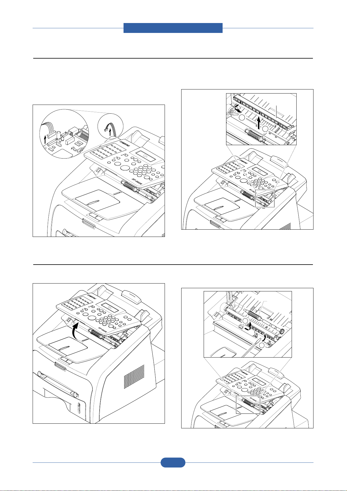
3.2 White Roller Ass,y
1. Open the OPE Unit. 2. Push the Bushing on RH end of the roller slightly inward,
then rotate it until it reaches the slot as shown below.
Then lift the roller out.
Note: Check the roller for any dirt. Clean with a soft cloth
dampened with water.
If the roller is heavily worn replace it with a new one.
3.3 Rear Cover
1. Remove the four screws securing the Rear Cover and
remove it, as shown below.
2. Unlatch the Face up Cover Securing the Rear Cover,
as shown below. Then lift the Face up Cover out.
Cover-Face up
2
White Roller
Bush
1
Rear Cover
3-2
Page 39

Service Manual
Disassembly and Reassembly
3.4 Side Cover L
1. Before you remove the Side Cover L, you should
remove:
- Remove handset and cradle.
2. Release the latches from Frame Ass,y in the direction
of the arrow, as shown below. Take care to disconnect
speaker harness.
3. If necessary, remove the two screws securing the
Speaker and remove it.
Speaker
Bracket
3.5 Side Cover R
1. Before you remove the Side Cover R, you should
remove:
- Rear Cover (see section 3.3)
2. Release the latches from Frame Ass'y in the direction
of the arrow, as shown below.
Side Cover R
Side Cover L
3-3
Page 40

Service Manual
Disassembly and Reassembly
3.6 OPE Unit
1. Before you remove the OPE Unit, you should remove:
- Rear Cover (see section 3.3)
2. Unplug the OPE connector from the Main PBA and
Scan Motor Harness, as shown below.
Then remove the two screws securing the Ground
Cable and remove it. Note the position of the bronze
earth plate.
3. Open the OPE and release the latch from Holder, as
shown below.
4. Carefully release the latches from Top Cover in the
direction of the arrow, as shown below.
5. Remove the two screws securing the Scan Upper
Ass'y and remove it.
Speaker
1
OPE Unit
2
OPE
Scan
Upper Ass'y
3-4
Page 41

Disassembly and Reassembly
6. Remove the seven screws securing the OPE PBA
and remove it.
OPE PBA
8. Remove the Key Pad from the OPE Cover.
Key Pad
7. Remove the Contact Rubber from the OPE Cover.
Contact Rubber
Service Manual
3-5
Page 42

Service Manual
Disassembly and Reassembly
3-6
Samsung Electronics
1. Before you remove the ADF Rubber Pad, you should
remove:
- Rear Cover (see section 3.3)
- OPE Unit (see section 3.6)
2. Insert a flat-blade screwdriver into the slot as shown
below, and release the latches.
Take out the Rubber Holder and the Rubber Pad.
Note:
• When you reassemble the Rubber Pad, be sure that
the Rubber Pad and Holder fit into the Guide Boss
and the Holder latches fit into the corresponding holes.
Then push firmly until it clicks.
• Clean the surface of the Rubber Pad with ethyl alcohol.
After wiping it, be sure to dry it. Check the rubber for
wear. If the wear reaches 1/2 it's original thickness,
replace it with a new one.
3.7 ADF Rubber Pad
Rubber Pad
Rubber Holder
Page 43
Service Manual
Disassembly and Reassembly
3-7
Samsung Electronics
1. Before you remove the CIS, you should remove:
- White Roller Ass'y (see section 3.2)
- Rear Cover (see section 3.3)
2. Unplug the CIS connector from the Main PBA. (CN14)
3. Unlatch the CIS using a flat-blade screwdriver and
release it, as shown below. Disconnect harness from
CIS unit.
3.8 CIS
CIS
CIS
1. Open the OPE Unit. 2. Pull up the Exit Roller using a flat-blade screwdriver
and remove it, as shown below.
3.9 Exit Roller
CIS
1
2
Exit Roller
2
1
Page 44

Service Manual
Disassembly and Reassembly
3-8
Samsung Electronics
1. Take out the Cassette.
2. Open the Front Cover.
3. Unlatch the Front Cover from the Frame Ass'y. Then
remove the Front Cover, as shown below.
3.10 Front Cover Ass'y
Cassette
Front Cover
Page 45

Disassembly and Reassembly
3.11 Scan Ass'y
1. Before you remove the Scan Ass'y, you should
remove:
- Rear Cover (see section 3.3)
- Side Cover L (see section 3.4)
- Side Cover R (see section 3.5)
- Front Cover (see section 3.10)
2. Unplug the three connectors (OPE, CIS, scan motor)
from the Main PBA. Then remove the two Ground
Cables, as shown below.
OPE
CIS
CIS
OPE
3. Remove the four screws securing the Top Cover and
remove the Scan Ass'y, as shown below.
Scan Ass'y
Service Manual
3-9
Page 46

Disassembly and Reassembly
3.12 Scan Motor Ass'y
1. Before you remove the Scan Motor Ass'y, you should
remove:
- Rear Cover (see section 3.3)
- Side Cover L (see section 3.4)
- Side Cover R (see section 3.5)
- OPE Unit (see section 3.6)
- Front Cover (see section 3.10)
- Scan Ass'y (see section 3.11)
2. Open the OPE Unit.
3. Remove the three silver screws securing the Scan
Motor Ass'y and remove it.
Scan Motor Ass'y
4. If necessary, remove the one screw securing the Scan
Motor and release the latches from Motor Bracket in
the direction of the arrow, as shown below.
1
2
Scan Motor
Service Manual
3-10
Page 47

Disassembly and Reassembly
3.13 ADF Roller
1. Before you remove the ADF Roller, you should
remove:
- Rear Cover (see section 3.3)
- Side Cover L (see section 3.4)
- Side Cover R (see section 3.5)
- Front Cover (see section 3.10)
- Scan Ass'y (see section 3.11)
- Scan Motor Ass'y (see chapter 3.12)
2. Carefully release the ADF Gear from the ADF Roller,
as shown below.
1
3. Carefully release the ADF Roller from Top Cover in
the direction of the arrow, as shown below.
2
1
ADF Roller
2
ADF Gear
Service Manual
3-11
Page 48

Disassembly and Reassembly
3.14 Sub Hook PBA
1. Before you remove the Sub Hook PBA, you should
remove:
- Rear Cover (see section 3.3)
- Side Cover L (see section 3.4)
2. Unplug the one connector from the Sub Hook PBA,
as shown below.
3. Remove the one screws securing the Sub Hook PBA
and remove it.
Sub Hook PBA
Service Manual
3-12
Page 49

Disassembly and Reassembly
3.15 Drive Ass'y
1. Before you remove the Drive Ass'y, you should
remove:
- Rear Cover (see section 3.3)
- Side Cover L (see section 3.4)
2. Remove the six screws securing the Drive Ass'y and
remove it. Then unplug the one connector from the
Drive Motor, as shown below.
Note : When re-fitting the Drive Ass’y tighten the screws
in the order that they are numbered on the base
plate.
3.16 DC-Fan
1. Before you remove the Fan, you should remove:
- Rear Cover (see section 3.3)
- Side Cover R (see section 3.5)
Drive Ass'y
2. Unplug the one connector from the SMPS, as shown
below. Then take out the Fan.
Service Manual
3-13
DC Fan
Page 50

Disassembly and Reassembly
3.17 Exit Cover Ass'y
1. Before you remove the Exit Cover Ass'y, you should
remove:
- Scan Ass'y (see section 3.11)
- Sub High PBA (see section 3.14)
2. Remove the four screws securing the Exit Cover Ass'y
and remove it, as shown below.
Exit Cover Ass'y
3. Remove the Exit Gear and Bearing using a flat-blade
screwdriver, as shown below.
Then take out the Exit Roller.
Exit Gear
Bearing
2
Exit Roller
1
Service Manual
3-14
Page 51

Disassembly and Reassembly
3.18 LSU-Unit
1. Before you remove the LSU, you should remove:
- Scan Ass'y (see section 3.11)
2. Unplug the two connectors from the LSU, as shown
below.
3. Remove the four screws securing the LSU and
remove it.
LSU
3.19 Engine Shield Ass'y
1. Before you remove the Engine Shield Ass'y, you
should remove:
- Rear Cover (see section 3.3)
- Side Cover L (see section 3.4)
- Side Cover R (see section 3.5)
2. Remove the twelve screws securing the Engine Shield
Ass'y and remove it. Then unplug the all connectors
from the SMPS and Main PBA, Main High PBA.
Engine Shield
Ass'y
Service Manual
3-15
Page 52

Disassembly and Reassembly
3.20 Main PBA
1. Before you remove the Main PBA, you should
remove:
- Engine Shield Ass,y (see section 3.19)
2. Remove the three screws securing the Main PBA and
remove it. Then carefully release the latches from
Supporter, as shown below.
Main PBA
2
Supporter
1
Service Manual
3-16
Page 53

Disassembly and Reassembly
3.21 SMPS
1. Before you remove the SMPS, you should remove:
- Engine Shield Ass,y (see section 3.19)
2. Remove the three screws securing the Inlet Bracket
and remove it.
Inlet Bracket
4. Remove the four screws securing the SMPS and
remove it. Then Lift the SMPS out, as shown below.
SMPS
3. Unplug one connector.
Service Manual
3-17
Page 54

Disassembly and Reassembly
3.22 Fuser Ass'y
1. Before you remove the Fuser Ass'y, you should
remove:
- Engine Shield Ass,y (see section 3.19)
2. Unplug the two connectors from the Main PBA and
SMPS, as shown below. Then remove the four
screws securing the Fuser Ass'y and remove it.
4. Remove the two screws securing the Halogen Lamp.
Then take out the Halogen Lamp from the Heat
Roller, as shown below.
Heat Roller
Fuser Ass'y
Halogen Lamp
3. Remove the two screws securing the Thermostat.
Then lift the Thermostat out.
Thermostat
5. Remove one screw securing the Idle Gear and
remove it.
Idle Gear
Service Manual
3-18
Page 55

Disassembly and Reassembly
6. Remove the four screws securing the Fuser Cover
and remove it, as shown below.
Claw
Fuser Cover
7. Unwrap the Thermister Harness, as shown below.
8. Remove the one screw securing the Thermister and
remove it, as shown below.
Thermister
Thermister Harness
Service Manual
3-19
Page 56

Service Manual
Disassembly and Reassembly
3-20
Samsung Electronics
1. Before you remove the Transfer Ass'y, you should
remove:
- LSU (see section 3.18)
2. Remove the three screws securing the Transfer Earth
and remove it.
3. Unplug the PTL Holder connector, then remove the
PTL Holder and PTL Lens, as shown below.
4. Release the frame latch at the R side of the Transfer
roller and lift the roller out. Release the latch on each
bush and lift them out.
3.23 Transfer Ass'y
Transfer
Earth
PTL
Holder
PTL
Lens
Transfer
Roller
Bush
Page 57

Service Manual
Disassembly and Reassembly
3-21
Samsung Electronics
1. Before you remove the Feed Ass'y, you should
remove:
- Scan Ass'y (see section 3.11)
- Drive Ass'y (see section 3.15)
- LSU (see section 3.18)
2. Remove the two screws securing the Paper Guide
and remove it.
3. Pull up the Feed Idle Bush and Feed Idle Shaft, as
shown below.
4. Remove the three screws securing the Feed Bracket
and remove it.
5. Remove the Idle Gear and Feed Gear2.
3.24 Feed Ass'y
Paper Guide
Feed Bracket
Bush
Feed Idle
Shaft
Feed Gear2
Idle Gear
Page 58

Service Manual
Disassembly and Reassembly
3-22
Samsung Electronics
6. Remove the Feed Gear1 Ass'y. 7. Pull up the Feed Roller and Feed Roller1.
Feed Gear1
Ass'y
Feed Roller
Feed Roller1
Page 59

Service Manual
Disassembly and Reassembly
3-23
Samsung Electronics
1. Before you remove the Pick up Ass'y, you should
remove:
- Scan Ass'y (see section 3.11)
- Drive Ass'y (see section 3.15)
- LSU (see section 3.18)
- Engine Shield Ass,y (see section 3.19)
2. Remove the Pick up Gear Ass,y.
3. Take out the Pick up Ass'y, as shown below.
3.25 Pick up Ass'y
Pick up Ass'y
1
2
Bush
1. Before you remove the Solenoid, you should remove:
- Scan Ass'y (see section 3.11)
- Feed Ass'y (see section 3.25)
- Pick up Ass'y (see section 3.26)
2. Remove the two screws securing the Manual
Solenoid and Pick up Solenoid.
Then remove Manual Solenoid and Pick up Solenoid.
3.26 Solenoid
(Pick up)
Solenoid
(Manual)
Solenoid
Pick up Gear
Ass'y
Page 60

Page 61

Service Manual
Alignment & Troubleshooting
4. Adjustment and Troubleshooting
4.1 Alignment and Adjustments
4.1.1 Paper path
ADF Part
PTL
P
I
C
K
/
R
PR
CR
DR
SR
TR FR
OPC
L S U
Fuser
Toner Cartridge
1
2
3
4
5
6
8
7
Engine Part
ADF R
10
9
ER
WR
4-1
Page 62

Service Manual
Alignment & Troubleshooting
4.1.1.1 Copy & Scan Document Path
ADF Part
ADF R
10
9
ER
WR
4-2
Page 63

Service Manual
Alignment & Troubleshooting
4.1.1.2 Printer Paper Path
1) After receiving print job the printer feeds printing paper from the cassette or manual feeder.
2) The fed paper passes the paper feeding sensor. (Jam 0 occurs if the sensor is not operated within a certain time)
3) After passing the feed sensor the paper passes through the print process to the paper exit sensor.
(Jam 1 occurs if the sensor is not operated by the paper’s leading edge within a certain time)
4) After passing the exit sensor paper exits from the set. (Jam 2 occurs if the trailing edge of the paper
does not pass the exit sensor within a certain time)
Engine Part
1
2
3
4
Paper Input (Cassette)
Paper Input (Manual Feed)
Paper Out (Face Down)
5
6
7
Paper Empty Sensor (Cassette)
Paper Feed Sensor
Paper Exit Sensor
Paper Empty Sensor (Manual)
PTL
P
I
C
K
/
R
PR
CR
DR
SR
TR FR
OPC
L S U
Fuser
Toner Cartridge
1
2
3
4
5
6
7
4-3
Page 64

Service Manual
Alignment & Troubleshooting
4.1.2 Clearing Paper Jams
Occasionally paper can become jammed during a print job. Some of the causes include:
• The tray is loaded improperly or overfilled.
• The tray has been pulled out during a print job.
• The front cover has been opened during a print job.
• Paper was used that does not meet paper specifications.
• Paper that is outside of the supported size range was used.
If a paper jam occurs the On Line/Error LED on the control panel lights red. Find and remove the jammed
paper. If you don't see the paper, open the covers.
Do not use a tweezers, pincers or other metal tools when removing a jam.
This could damage the internal mechanism causing print quality problems or possibly electrical shock..
Paper Jam0
PTL
P
I
C
K
/
R
PR
CR
DR
SR
TR FR
Empty Sensor
OPC
L S U
Fuser
Toner Cartridge
EXIT
Sensor
Feed
Sensor
MP Sensor
Paper Jam1
PTL
P
I
C
K
/
R
PR
CR
DR
SR
TR FR
Empty Sensor
OPC
L S U
Fuser
Toner Cartridge
EXIT
Sensor
Feed
Sensor
MP Sensor
Paper Jam2
PTL
P
I
C
K
/
R
PR
CR
DR
SR
TR FR
Empty Sensor
OPC
L S U
Fuser
Toner Cartridge
EXIT
Sensor
Feed
Sensor
MP Sensor
Bypass Jam
L S U
Fuser
EXIT
PR
Sensor
Empty Sensor
CR
DR
OPC
SR
PTL
TR FR
Toner Cartridge
MP Sensor
Feed
Sensor
R
/
K
C
I
P
4-4
Page 65

Service Manual
Alignment & Troubleshooting
4.1.2.1 Clearing Document Jams
When a document jams while passing through the ADF (Automatic Document Feeder) "Document Jam" appears on the
display.
4.1.2.1(a) Input Misfeed
1) Remove the remaining documents from the ADF.
2) Pull the jammed document gently out of the ADF.
3) Load the documents back into the ADF.
NOTE :To prevent document jams do not use thick, thin or mixed documents.
4-5
Page 66

Alignment & Troubleshooting
4.1.2.1(b) Exit Misfeed
1) Remove the remaining documents from the ADF.
2) Open the control panel by gripping its lower front edge and lifting gently.
3) Pull the document gently out of the ADF.
4) Close the control panel, then load the documents back into the ADF.
Service Manual
4-6
Page 67

Service Manual
Alignment & Troubleshooting
4.1.2.2 Clearing Paper Jams
When a paper jam occurs, "Paper Jam" appears on the display. Refer to the table below to locate and clear the paper jam.
To avoid tearing the paper pull the jammed paper out gently and slowly. Follow the steps on the next pages to clear the jam.
4.1.2.2.1 In the Paper Tray
1) Open and close the front cover. The jammed paper is automatically ejected from the machine. If the paper is not ejected
continue to step 2.
2) Pull the paper tray open.
Message Location of Jam
Paper Jam 0 In the paper tray.
Paper Jam 1 In the fuser area or around the toner
cartridge.
Paper Jam 2 In the paper exit area
Bypass Jam In the manual feeder
4-7
Page 68

Alignment & Troubleshooting
3) Remove the jammed paper by gently pulling it straight out.
If there is any resistance and the paper does not move when you pull or if you cannot see the paper in this area, skip to
the fuser area around the toner cartridge.
4) Insert the paper tray into the machine until it snaps into place.
5) Open and close the front cover to resume printing.
Service Manual
4-8
Page 69

Service Manual
Alignment & Troubleshooting
4.1.2.3 In the Paper Exit Area
1) Open and close the front cover. The jammed paper is automatically ejected from the machine. If the paper is not
ejected continue to step 2.
2) Gently pull the paper out of the front output tray. Skip to step 6.
If there is any resistance and the paper does not move when you pull or if you cannot see the paper in the front output tray continue to step 3.
3) Open the rear cover.
4) Remove the jammed paper by gently pulling it straight out.
5) Close the rear cover.
6) Open and close the front cover to resume printing.
4-9
Page 70

Service Manual
Alignment & Troubleshooting
4.1.2.4 In the Fuser Area or Around the Toner Cartridge
NOTE :The fuser area is hot. Take care when removing paper from the machine.
1) Open the front cover and lightly push down on the cartridge then pull to take it out.
2) Remove the jammed paper by gently pulling it straight out.
3) Replace the toner cartridge and close the front cover.
Printing automatically resumes.
4-10
Page 71

Service Manual
Alignment & Troubleshooting
4.1.2.5 In the Bypass Tray
"Bypass Jam" appears on the display when you try to print using the manual feeder and the machine does not detect
paper due to no paper or improper paper loading.
The error message may also occur when the paper is not properly fed into the machine through the manual feeder.
In this case pull the paper out of the machine.
4.1.2.6 Tips for Avoiding Paper Jams
By selecting the correct paper types most paper jams can be avoided. When a paper jam occurs follow the steps outlined in page 6-10
• Follow the procedures on page 6-10 when you load paper. Ensure that the adjustable guides are positioned correctly.
• Do not overload the paper tray. Ensure that the paper is below the paper capacity mark on the inside wall of the paper tray.
• Do not remove the paper from the tray while your machine is printing.
• Flex, fan and straighten the paper before loading.
• Do not use creased, damp or highly curled paper.
• Do not mix paper types in the paper tray.
• Use only recommended print materials. See "Paper Specifications" in the user manual.
• Ensure that the print side of print materials is facing down in the paper tray and facing up in the Bypass tray.
4-11
Page 72

Service Manual
Alignment & Troubleshooting
1. Paper Setting
Paper Type
Paper Size
2. Copy Setup
Default-Change
Timeout
3. Fax Setup
Ring to Answer
Darkness
Redial Term
Redials
MSG Confirm.
Auto Report
Auto Reduction
Discard Size
Receive Code
4. Fax Feature
Delay Fax
Add Page
Cancel Job
Delay Rx Poll
5. Advanced Fax
Send Forward
RCV Forward
Toll Save
Junk Fax Setup
Secure Receive
Prefix Dial No
Stamp RCV Name
ECM Mode
6. Reports
Phone Book
Send Report
RCV Report
System Data
Scheduled Jobs
MSG Confirm.
Junk Fax List
7. Sound/Volume
Speaker
Ringer
Key Sound
Alarm sound
8. Machine Setup
Machine ID
Date &Time
Clock Mode
Language
Power Save
Ignore Toner
USB Mode
9. Maintenance
Clean Drum
Notify toner
Clear Memory
Adjust Shading
4.1.3 User Mode(SF-565PR)
The table below shows the map of User settings available in User Mode. These are fully described in the
User Guide and are not included here.
4-12
Page 73

Service Manual
Alignment & Troubleshooting
4.1.4 Tech Mode
4.1.4.1 How to Enter Tech Mode
In service (tech) mode the technician can check the machine and perform various tests to help with failure
diagnosis.
When in Tech mode the machine still performs all normal operations.
To enter the Tech mode
To enter the Tech mode press in sequence and the LCD
briefly displays 'TECH', the machine has entered service (tech) mode.
4.1.4.2 Tech Mode settings map
4-13
Page 74

Service Manual
Alignment & Troubleshooting
4.1.4.3 Data Setup
SEND LEVEL
You can set the level of the transmission signal. Typically, the Tx level should be under -12 dBm.
Caution : The Send Fax Level is set to the best condition during manufacture. Never change settings arbitrarily.
DIAL MODE
This function can choose the dialing method.
*Default : Dial (Dial/Pulse)
MODEM SPEED
You can set the maximum modem speed.
When the fax establishes communication with a remote set the value of the maximum modem speed is
checked for both transmitter and receiver. The lowest value is used. It is best set at 33.6Kbps, the default
setting.
ERROR RATE
When the error rate is about exceed the set value, the Baud rate automatically adjusts to 2400 bps.
This ensures that the error rate remains below the set value.
You can select the rate between 5% and 10%.
CLEAR ALL MEMORY
The function resets the system to factory default settings.
This function is used to reset the system to the initial value when the product is functioning abnormally. All the values are returned to the default values, and all the information which was set by the
user will be erased.
< Method >
1. Select the [MEMORY CLEAR] in TECH MODE.
2. Push the ENTER button.
3. Select your country. (There are four country groups. Refer to the table below.)
4. Push the ENTER button then it will clear all memory.
NOTICE : Always perform a memory clear after replacing the main board, otherwise the system may
not operate properly.
Country Group USA/Canada UK Russia South Africa
USA/Canada UK Russia South Africa
Mexico Germany India
Brazil France Oman
Italy Poland
Spain Bangladesh
Austria Kuwait
Netherlands Morocco
Belgium Algeria
Country Portugal Pakistan
Sweden UAE
Norway Bahrain
Denmark Sri Lanka
Finland Saudi Arabia
Switzerland Chile
Greece Peru
Ireland Argentina
Turkey Hungary
Romania
Bulgaria
Czech
4-14
Page 75

Alignment & Troubleshooting
FLASH UPGRADE
There are 2 methods to update the Flash Rom, Local and Remote.
(1) Local Machine
• RCP
(Remote Control Panel) mode
This method is for Parallel Port or USB Port. Connect the PC and activate the RCP (Remote Control Panel) to
upgrade the Firmware.
< Method >
How to Update Firmware using RCP
1. Connect PC and Printer with a USB Cable.
2. Run the RCP utility and select Firmware Update.
3. Search for the Firmware file to be used to update the set using the Browse Icon.
4. Click the Update icon. The firmware file is transmitted to the Printer automatically and the printer is
initialized when the download completes.
5. Click the Refresh icon and check that the updated version numbers are displayed.
• DOS Command mode
This method is ONLY for Parallel Port. Connect the PC to the set using a Parallel Cable and enter the DOS
Command to upgrade the firmware.
< Method >
1. First of all you need the following files : down.bat, down_com.bin, fprt.exe, and Rom File: (file name for
upgrade). Ensure you save ALL of these files in the same folder.
2. At the DOS prompt enter the correct command (as shown below) and push the enter key.
Then the upgrade will automatically take place..
3. There are two commands use the correct one depending on the condition of the set..
* When the product is in the idle condition
down "rom file"
* When the product is in Ready condition
(TECH MODE --> DATA SETUP --> FLASH UPGRADE --> LOCAL)
fprt "rom file"
4. Do not turn off the power during the upgrade process.
(2) Remote FAX
It is possible to use a set that already has the latest firmware to upgrade a remote set remotely using the telephone system.
< Method >
1. On the set that has the latest firmware set it toi transmit the upgrade:(TECH MODE •DATA SETUP•••• FLASH UPGRADE•••• REMOTE)
2. Enter the telephone number of the set that needs to be upgraded.
(Several faxes can be upgrade at the same time. In this case, enter each fax number.)
3. When the enter button is pressed the set sends the firmware file by calling designated fax number.
(Around 10~15 minutes are needed to send the file.)
Service Manual
< Caution >
1. The Sending and Receiving fax machines MUST be the same model.
2. The sending fax must be set up in ECM mode and the Receiving fax memory must be 100%.
If not the function will not work.
4-15
Page 76

Service Manual
Alignment & Troubleshooting
4.1.4.4 Machine Test
SWITCH TEST
Use this feature to test all keys on the operation control panel. The result is displayed on the LCD
window each time you press a key.
MODEM TEST
Use this feature to hear various transmission signals to the telephone line from the modem and to
check the modem, amplifier and speaker. If no transmission signal sound is heard, it means the
modem part of the main board, amplifier, speaker or speaker harness is faulty.
DRAM TEST
Use this feature to test the machine's DRAM. The result appears in the LCD display.
If all memory is working normally, the LCD shows << O K >>
ROM TEST
Use this feature to test the machine's ROM. The result and the software version appear in the LCD display.
• FLASH VER : 1.00 V
• ENGINE VER :1.00V
PATTERN TEST
Using this pattern printout you can check that the printer mechanism is functioning properly.
This function is for factory manufacturing use only.
SHADING TEST
The function is used to set the optimum scan quality determined by the specific characteristics of
the CIS (Contack Image Sensor). If copy
image quality is poor perform this function
to check the condition of the CIS unit.
< Method >
1. Select the [Shading Test] in
TECH MODE(Manu, #, 1934).
2. Push the ENTER button and an image
will be scanned.
3. After scanning the CIS SHADING
PROFILE will be print out.
4. If the printed image is different to the
sample image shown the CIS is defective.
NOTICE : When you test the CIS, make
sure that the cover is closed.
4-16
Page 77

Service Manual
Alignment & Troubleshooting
4.1.4.5 Report
PROTOCOL LIST
This list shows the sequence of the CCITT group 3 T.30 protocol during the most recent sending or receiving
operation. Use this list to check for send and receive errors. If a communication error occurs while the machine
is in TECH mode, the protocol list will print automatically.
SYSTEM DATA
This list provides a list of the user system data settings and tech mode settings.
4-17
Page 78

Service Manual
Alignment & Troubleshooting
4.1.5 Engine Test Mode
The Engine Test Mode supplies useful functions to check the condition of the print engine. It tests the condition of each device and displays the result of the test on the LCD. It is divided into 5 functions (0~4), and
these are shown below.
4.1.5.1 To enter the Engine Test Mode
To enter the Engine Test mode
Press in sequence, and the LCD briefly displays
‘Engine Test’, the machine has entered Engine Test Mode.
Press “0”, “1”, “2”, “3” or “4” to select the Test No. (see list below – left hand column)
4.1.5.2 Diagnostic
NO. Sub No. Engine test Remark
0 1 Motor Test 1 : On, 2 : Off – next test selected
2 Pick Up Test 1 : On, 2 : Off – next test selected
3 Fan Test 1 : On, 2 : Off – next test selected
4 Manual Clt Test 1 : On, 2 : Off – next test selected
5 PTL Test 1 : On, 2 : Off – next test selected
1 1 LSU Motor Test 1 : On, 2 : Off – next test selected
2 LSU Hsync Test 1 : On, 2 : Off – next test selected
3 LD Test 1 : On, 2 : Off – next test selected
2 1 Feed Sensor Test 1. Check : read the sensor
2. Next : Next Sensor test
2 Exit Sensor Test 1. Check : read the sensor
2. Next : Next Sensor test
3 Cover Sensor Test 1. Check : read the sensor
2. Next : Next Sensor test
4 Empty Sensor Test 1. Check : read the sensor
2. Next : Next Sensor test
5 Manual Sensor Text 1. Check : read the sensor
2. Next : Next Sensor test
3 1 Therm ADC 180 1 : On, 2 : Off (maintain the fusing temp. 80C)
2 Therm ADC 140 1 : On, 2 : Off (maintain the fusing temp. 135C)
3 Therm ADC 120 1 : On, 2 : Off (maintain the fusing temp. 160C)
4 Therm ADC 100 1 : On, 2 : Off (maintain the fusing temp. 191C)
4 1 MHV Test 1 : On, 2 : Off (-1550V ± 50V)
2 Dev Bias Test 1 : On, 2 : Off (-430V ± 20V)
3 THV EN/NEG Test 1 : On, 2 : Off (-1000V +300V/-150V)
4 THV ON (1300V) 1 : On, 2 : Off (+1300V ± 20V)
5 THV ADC 1300V 1 : On, 2 : Off (ADC Value : 101 ± 5)
6 THV ADC 600V~3500V 1 : On, 2 : Off (Compare each ADC Value)
4-18
Page 79

Service Manual
Alignment & Troubleshooting
4.1.6 Identify Sale Date
This function confirms the date that consumer used the product for the first time.
When the consumer first operate the machine, it will start the scan and page counters.
The time the machine was first used is remembered.
These settings are remembered after memory reset (Clear All Memory).
< Method >
Press MENU, #, 1, 9, 3, # in sequence. Firmware version is displayed on LCD.
Press 1( in the number keypad) : The LCD display shows "Updated date"
Press 2( in the number keypad) : The LCD display shows "Product first use date"
4-19
Page 80

Service Manual
Alignment & Troubleshooting
4.1.7 Consumables and Replacement Parts
The life cycle outlined below is a general guideline for maintenance purposes and is for reference only.
Environmental conditions (temperature, humidity, dust etc.) and actual use can cause these figures to vary.
COMPONENT REPLACEMENT CYCLE
ADF Rubber 20,000 Pages
ADF Roller 60,000 Pages
Pick-up Roller 60,000 Pages
Friction Pad 60,000 Pages
Transfer Roller 60,000 Pages
Fuser 60,000 Pages
Toner Cartridge 3,000 Pages (A4 ISO 19752 Standard)
4-20
Page 81

Service Manual
Alignment & Troubleshooting
4.1.8 Abnormal Image Printing and Defective Roller
If a mark or other printing defect occurs at regular intervals down the page it may be caused by a damaged or
contaminated roller. Measure the repetition interval and refer to the table below to identify the roller concerned.
No Roller Abnormal image period Kind of abnormal image
1 OPC Drum 75.5mm White spot, Block spot
2 Charge Roller 37.7mm Black spot
3 Supply Roller 37.0mm Horizontal density band
4 Develop Roller 35.2mm Horizontal density band
5 Transfer Roller 45.3mm Black side contamination/transfer fault
6 Heat Roller 66.3mm Black spot and fuser ghost
7 Pressure Roller 75.5mm Black side contamination
1
2
3
4
OPC Drum
Charge Roller
Supply Roller
Developing Roller
5
6
7
Transfer Roller
Heat Roller
Pressure Roller
L S U
Fuser
PR
CR
OPC
TR FR
Toner Cartridge
DR
SR
PTL
MP Sensor
R
/
K
C
I
P
4-21
Page 82

Service Manual
Alignment & Troubleshooting
4.1.9 Error Messages
The front panel displays the printer's status or error messages. Refer to the list below for an explanation of these
messages and how to clear problems. The messages and their meanings are listed in alphabetical order, with numbered
messages following.
[Bypass Jam]
Meaning: The machine has detected a paper feed problem from the BYPASS Tray.
Solution: Open the side Cover and clear the jam.
Cancel ?
1:Yes 2:No
Meaning: While storing the document in memory the memory has become full.
Solution: To cancel the fax job, press the ‘1’ button to accept “Yes.” If you want to send the
pages that were stored press the ‘2’ button to accept “No.” This will send ONLY
the pages stored. The remaining pages should be sent later when
more memory becomes available.
[Comm. Error]
Meaning: A problem with the fax communications has occurred.
Solution: Try again.
CRU Fuse Error
Meaning: The machine has a problem with recognizing the new toner cartridge.
Solution: Check the toner cartridge probrem.
Document Jam
Meaning: Loaded document has jammed in the ADF.
Solution: Clear the document Jam.
[Door Open]
Meaning: The front cover is not securely latched.
Solution: Close the cover until it clicks in place.
Group Not Available
Meaning: You have tried to select a group location where only a single location number can
be used, such as when adding locations for a multi-dial operation.
Solution: Just use a one-touch or speed dial number or dial a number manually using the
number keypad.
[Incompatible]
Meaning: The remote machine does not have the requested feature, such as a delayed
transmission.
Solution: Reconfirm the remote machine’s features.
4-22
Page 83

Alignment & Troubleshooting
[Jam 1] or [No Cartridge]
Meaning: Paper has jammed inside the unit, or the toner cartridge is not installed.
Solution: Clear the jam. Install the toner cartridge.
Line Busy
Meaning: The remote person did not answer or the line is already engaged.
Solution: Try again after a few minutes.
[Line Error]
Meaning: Your machine cannot connect with the remote machine or has lost contact
because of a problem with the phone line.
Solution: Try again. If the problem persists, wait an hour or so for the line to clear and try
again.Or, turn the ECM on.
Load Document
Meaning: You have attempted to set up a copy or fax operation with no document loaded.
Solution: Load a document and try again.
[Low Heat Error]
Meaning: There is a problem in the fuser unit.
Solution: Check thermostat, thermister contact point & Heating Lamp.
Open Heat Error
Meaning: Thermister is not connected to the main board or contact point is poor at power on.
Solution: Check thermostat, thermister contact point & Heating Lamp.
[Over Heat]
Meaning: The printer has overheated.
Solution: Your unit will automatically return to the standby mode when it cools down to
normal operating temperature. If failure persists, check the ELA HOU-FUSER.
[LSU Error]
Meaning: A problem has occurred in the LSU (Laser Scanning Unit).
Solution: Use TECH mode to test LSU. Replace the LSU
Memory Full
Meaning: The memory has become full.
Solution: Either delete unnecessary documents, or retransmit after more memory becomes
available, or split the transmission into more than one operation.
[No Answer]
Meaning: The remote machine did not answer after all the redial attempts.
Solution: Try again. Make sure the remote machine is OK.
Service Manual
4-23
Page 84

Alignment & Troubleshooting
NO. Not Assigned
Meaning: The speed dial location you tried to use has no number assigned to it.
Solution: Dial the number manually with the keypad, or assign the number.
[No Paper]Add Paper
Meaning: The paper cassette is empty. The printer system stops.
Solution: Load new paper in the paper tray.
Operation NotAssigned
Meaning: You are doing in the Add/ Cancel operation, but there is no jobs waiting.
Solution: Check the display to see if there is any scheduled job. The display should
indicate them in Standby mode, for example, Delay Fax.
[Paper Jam 0]Open/Close Door
Meaning: Paper has jammed in paper feeding area. Paper is jammed in pick-up unit
Solution: Press STOP and clear the jam.
[Paper Jam 1]Open/Close Door
Meaning: Paper has jammed inside the unit. Paper has jammed in paper exit unit.
Solution: Clear the jam.
[Paper Jam 2]Check Inside
Meaning: Paper has jammed inside the unit. Paper has jammed in fuser area.
Solution: Clear the jam.
Power Failure
Meaning: Power has turned off then on and the machine’s memory has not been saved.
Solution: You need to start again the job which you were trying to do before the power failure.
Retry Redial?
Meaning: The machine is waiting for the programmed interval to automatically redial.
Solution: You can press START to immediately redial, or STOP to cancel the redial operation.
[Stop Pressed]
Meaning: The Stop/Clear button is pressed during a copy or fax operation.
Solution: Try again.
[Toner Empty]
Meaning: The toner cartridge has run out. The machine stops printing.
Solution: Replace with a new toner cartridge.
[Toner Low]
Meaning: The toner cartridge is almost empty.
Solution: Take out the toner cartridge and gently shake it. By doing this, you can temporarily
reestablish printing operations."
Service Manual
4-24
Page 85

Adjustment and Troubleshooting
4.2 Troubleshooting
4.2.1 Procedure of Checkig the Symptoms
Before attempting to repair the printer first obtain a detailed description of the problem from the customer.
Power On
Indicate
Error Massage
Ready or
Power save
Test Print
printing
Quality is
Nomal?
Refer to "Solution
of Image Problem"
Refer to
Error Massage
<Chapter 4.1.9>
END
- No Power
- Power Module error
- Main PBA error
- LCD Panel error
OP Panel
ON?
Service Manual
4-25
Page 86

Adjustment and Troubleshooting
4.2.2 The cause and solution of image quality
1) Vertical Black Line and Band
Description: 1. Straight thin black vertical lines occur in the prnting
2. Dark black vertical bands occurrs in the printing
Digital Printer
Digital Printer
Digital Printer
Digital Printer
Digital Printer
Service Manual
4-26
Page 87

Adjustment and Troubleshooting
2) Vertical White Line
Description: White vertical voids in the image.
Digital Printer
Digital Printer
Digital Printer
Digital Printer
Digital Printer
Service Manual
4-27
Page 88

Adjustment and Troubleshooting
3) Horizontal Black Bands
Description: Dark or blurry horizontal stripes occur in the printing periodically
(These may occurs at regular intervals down the page.)
Digital Printer
Digital Printer
Digital Printer
Digital Printer
Digital Printer
1. Bad contacts on the toner
cartridge high voltage terminals.
Clean all HV terminals on the cartridge
and on the set frame. Ensure all toner
or paper dust particles are removed.
2. The rollers in the toner
cartridge may be contaminated.
1) Charge roller = 37.7 mm
2) Supply roller = 37 mm
3) Develop roller = 35.3 mm
4) Transfer roller = 45.3 mm
1. Clean the right Gear that has
relatively small tooth gap on the
OPC.
2. If the problem persists replace the
toner cartridge.
Service Manual
4-28
Page 89

Adjustment and Troubleshooting
4) Black/White Spot
Description: 1. Dark or blurry spots occur periodically in the printing
2. White spots occur periodically in the printing
Digital Printer
Digital Printer
Digital Printer
Digital Printer
Digital Printer
1. If dark or blurry black
spots occur periodically,
the rollers in the Developer may be
contaminated with foreign matte or paper particles.
(Charge roller : 37.7 mm interval
OPC drum : 75.5 mm interval)
Print several OPC cleaning Mode
Prints and then run the Self-test 2
or 3 times.
2. If faded areas or voids
occur in a black image at intervals
of 75.5 mm, or black spots occur elsewhere,
the OPC drum surface is damaged.
3. If a black image is partially
broken, the transfer voltage is abnormal or the
transfer roller's life has expired.
75.5 mm repetition: Examine the
surface of the OPC drum and
carefully clean with a soft, lint free
cloth. If unsuccessful replace the
cartridge.
37.7mm repetition: Replace the toner
cartridge
The transfer roller guarantees 60,000
sheets printing. If the roller's life is
expired, replace it.
Note. Cleaning the inside of the set to
remove excess toner particles or
paper dust will reduce the occurrence
of this problem.
Service Manual
4-29
Page 90

Adjustment and Troubleshooting
5) Light Image
Description: The printed image is light, with no ghost.
Digital Printer
Digital Printer
Digital Printer
Digital Printer
Digital Printer
Service Manual
4-30
Page 91

Adjustment and Troubleshooting
6) Dark image or Black
Description: The printed image is dark.
Digital Printer
Digital Printer
Digital Printer
Digital Printer
Digital Printer
Service Manual
4-31
Page 92

Adjustment and Troubleshooting
7) Uneven Density
Description: Print Density is uneven between left and right.
Service Manual
4-32
Page 93

Adjustment and Troubleshooting
8) Background
Description:Light dark background appears in whole area of the printing.
Digital Printer
Digital Printer
Digital Printer
Digital Printer
Digital Printer
The toner cartridge is basically
designed to print 3,000 sheets with
Std. image. If it prints more than
3,600 sheets with 2% coverage,
a background can occur.
Service Manual
4-33
Page 94

Adjustment and Troubleshooting
9) Ghost(1)
Description: Ghost occurs at 75.5 mm intervals of the OPC drum in the whole printing.
Digital Printer
Digital Printer
75.5 mm
Digital Printer
Digital Printer
Digital Printer
Digital Printer
Service Manual
4-34
Page 95

Adjustment and Troubleshooting
10) Ghost (2)
Description:
Ghost occurs at 75 mm intervals of the OPC drum in the whole printing.
(When printing on card stock or transparencies using manual feeder)
Digital Printer
Digital Printer
75 mm
Digital Printer
Digital Printer
Digital Printer
Digital Printer
When printing on card stock
thicker than normal paper or
transparencies such as OHP, higher
transfer voltage is
required.
Ensure that the correct paper type
is selected in the printer driver or
application software. Remember to
set back to normal paper after use.
Service Manual
4-35
Page 96

Adjustment and Troubleshooting
11) Ghost (3)
Description:
Digital Printer
Digital Printer
Digital Printer
Digital Printer
Digital Printer
Digital Printer
Ghost occurs at 66.3 or 75.5 mm intervals.
66.3 or 75.5 mm
1. Fuser contamination.
Disassemble the fuser and remove
any contamination on the rollers.
Clean any contamination from
between the Thermistor and the
Heat roller. (Caution: Take care not
to deform the rollers.)
Service Manual
4-36
Page 97

Adjustment and Troubleshooting
12) Ghost (4)
Description:
Digital Printer
Digital Printer
Digital Printer
Digital Printer
Digital Printer
Digital Printer
A White ghost occurs in a black image printing at 32 mm intervals.
32 mm
1. The life of the developer
may be expired.
2. Abnormal
output from the HVPS.
Problem in the toner cartridge,
replace the toner cartridge and try
to print out again.
Check the HVPS supply voltage.
Clean all HV terminals on the
cartridge and on the set. Replace
the HVPS if the problem persists.
Service Manual
4-37
Page 98

Adjustment and Troubleshooting
13) Stains on the Face of Page
Description: The background on the face of the printed page is stained.
Digital Printer
Digital Printer
Digital Printer
Digital Printer
Digital Printer
1. Toner leakage due to improperly
sealed toner cartridge.
2. If the transfer roller is
contaminated, stains on the face of
page will occur.
Replace the toner cartridge.
If the transfer roller is
contaminated, run PC Cleaning
Mode Print 2 or 3 times.
And perform Self-Test 2 or 3 times
to remove contamination.
Service Manual
4-38
Page 99

Adjustment and Troubleshooting
14) Stains on Back of Page
Description: The back of the page is stained at 45.3 or 75.5 mm intervals.
Digital
Digital Pri
Digital Printer
Digital Printer
Digital Printer
1. 45.3mm : Transfer roller
is contaminated.
Perform the OPC Cleaning Mode
Print 2 or 3 times. Run Self-Test to
remove the contamination from the
transfer roller.
Note. Replace the transfer roller if
contaminated severely.
2. 75.5mm : Pressure roller
is contaminated.
Disassemble the fuser and clean
the H/R(Heat Roller) and P/R
(Pressure roller). Check and clean
the area between the H/R and the
Thermistor. (Caution: Take care
not to deform the rollers.)
Service Manual
4-39
Page 100

Adjustment and Troubleshooting
15) Blank Page Print out (1)
Description: Blank page is printed.
1. Bad ground contacts in
OPC and/or toner cartridge.
1. Check if the Ground-OPC or the
OPC Ground Zener diode are
defective or open circuit.
(set inside left side)
2. Remove contamination of the
terminals on the toner cartridge
and the unit.
Service Manual
4-40
 Loading...