

Page 1
• This PDF catalog is downloaded from the website of Murata Manufacturing co., ltd. Therefore, it’s specifications are subject to change or our products in it may be discontinued without advance notice. Please check with our
!Note
sales representatives or product engineers before ordering.
• This PDF catalog has only typical specifications because there is no space for detailed specifications. Therefore, please approve our product specifications or transact the approval sheet for product specifications before ordering.
CERAFILr
(Filters/Traps/Discriminators)
for Audio/Visual Equipment
P50E.pdf
10.2.9
Cat.No.P50E-4
Page 2

• This PDF catalog is downloaded from the website of Murata Manufacturing co., ltd. Therefore, it’s specifications are subject to change or our products in it may be discontinued without advance notice. Please check with our
!Note
• This PDF catalog has only typical specifications because there is no space for detailed specifications. Therefore, please approve our product specifications or transact the approval sheet for product specifications before ordering.
• Please read rating and !CAUTION (for storage, operating, rating, soldering, mounting and handling) in this catalog to prevent smoking and/or burning, etc.
!Note
sales representatives or product engineers before ordering.
• This catalog has only typical specifications because there is no space for detailed specifications. Therefore, please approve our product specifications or transact the approval sheet for product specifications before ordering.
P50E.pdf
10.2.9
for EU RoHS Compliant
• All the products in this catalog comply with EU RoHS.
• EU RoHS is "the European Directive 2002/95/EC on the Restriction of the Use
of Certain Hazardous Substances in Electrical and Electronic Equipment".
• For more details, please refer to our website 'Murata's Approach for EU RoHS'
(http://www.murata.com/info/rohs.html).
Page 3
• This PDF catalog is downloaded from the website of Murata Manufacturing co., ltd. Therefore, it’s specifications are subject to change or our products in it may be discontinued without advance notice. Please check with our
!Note
• This PDF catalog has only typical specifications because there is no space for detailed specifications. Therefore, please approve our product specifications or transact the approval sheet for product specifications before ordering.
• Please read rating and !CAUTION (for storage, operating, rating, soldering, mounting and handling) in this catalog to prevent smoking and/or burning, etc.
!Note
sales representatives or product engineers before ordering.
• This catalog has only typical specifications because there is no space for detailed specifications. Therefore, please approve our product specifications or transact the approval sheet for product specifications before ordering.
P50E.pdf
10.2.9
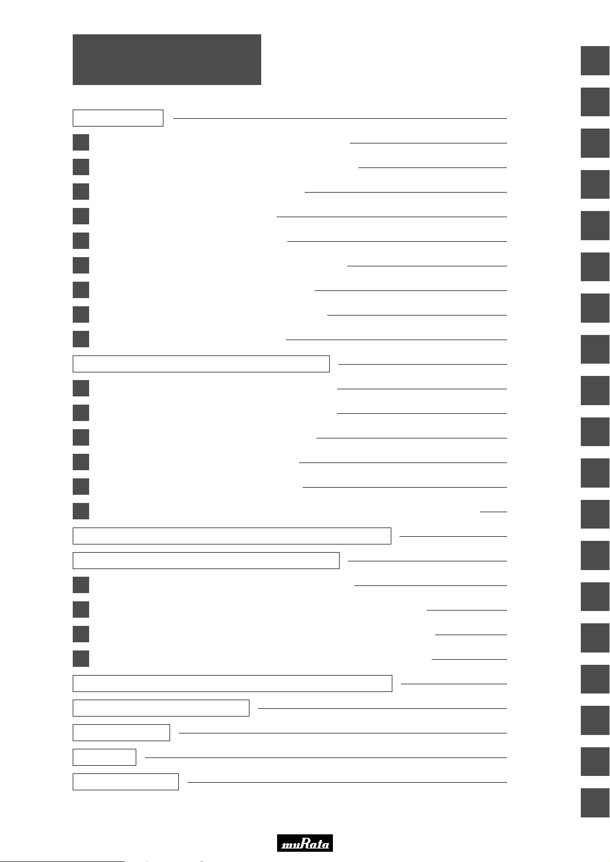
CONTENTS
Part Numbering 2
1
CERAFILr 10.7MHz Small Chip Type SFECF Series 5
2
CERAFILr 10.7MHz Chip Type SFECV/SFECK Series 11
3
CERAFILr 10.7MHz Standard Lead Type 14
4
CERAFILr 10.7MHz Low Loss Type 17
5
CERAFILr 10.7MHz Low Profile Type 20
6
CERAFILr 10.7MHz Low Spurious Response Type 23
7
CERAFILr 10.7MHz Wide Bandwidth Type 26
8
CERAFILr 10.7MHz Narrow Bandwidth Type 28
9
CERAFILr 10.7MHz for FM-IF Tuners 31
CERAFILr 10.7MHz Related Data on Lead Type 34
CERAFILr and "CERAFIL" in this catalog are
the trademarks of Murata Manufacturing Co., Ltd.
1
2
3
4
5
6
7
8
10
CERAFILr 4.5-6.5MHz Chip Type SFSKA Series 35
11
CERAFILr 2.3-5.7MHz Chip Type SFSKB Series 38
12
CERAFILr 455kHz Chip Type SFPKA Series 43
13
CERAFILr 455kHz SFULA/SFZLA Series 45
14
CERAFILr 455kHz SFPLA/CFWLA Series 48
15
CERAFILr 455kHz for AM Stereo Wide Bandwidth Type SFPLA/CFWLA/CFULA Series
CERAFILr 455kHz SFp Series Temperature Characteristics 52
CERAFILr 455kHz SFp Series Application Circuit 53
16
Ceramic Trap 4.5-6.5MHz Chip Type TPSKA Series 54
17
Ceramic Trap 4.5-6.5MHz Chip Type Double Traps TPWKA Series 56
18
Ceramic Discriminator 10.7MHz Ultra Thin Chip Type CDSCB Series 57
19
Ceramic Discriminator 10.7MHz Standard Lead Type CDALF Series 62
Ceramic Discriminator 10.7MHz Applied IC Reference Table 66
50
9
10
11
12
13
14
15
16
Notice (Soldering and Mounting) 68
Notice (Handling) 72
Packaging 79
Part Number Index 87
17
18
19
Page 4
• This PDF catalog is downloaded from the website of Murata Manufacturing co., ltd. Therefore, it’s specifications are subject to change or our products in it may be discontinued without advance notice. Please check with our
!Note
• This PDF catalog has only typical specifications because there is no space for detailed specifications. Therefore, please approve our product specifications or transact the approval sheet for product specifications before ordering.
• Please read rating and !CAUTION (for storage, operating, rating, soldering, mounting and handling) in this catalog to prevent smoking and/or burning, etc.
!Note
sales representatives or product engineers before ordering.
• This catalog has only typical specifications because there is no space for detailed specifications. Therefore, please approve our product specifications or transact the approval sheet for product specifications before ordering.
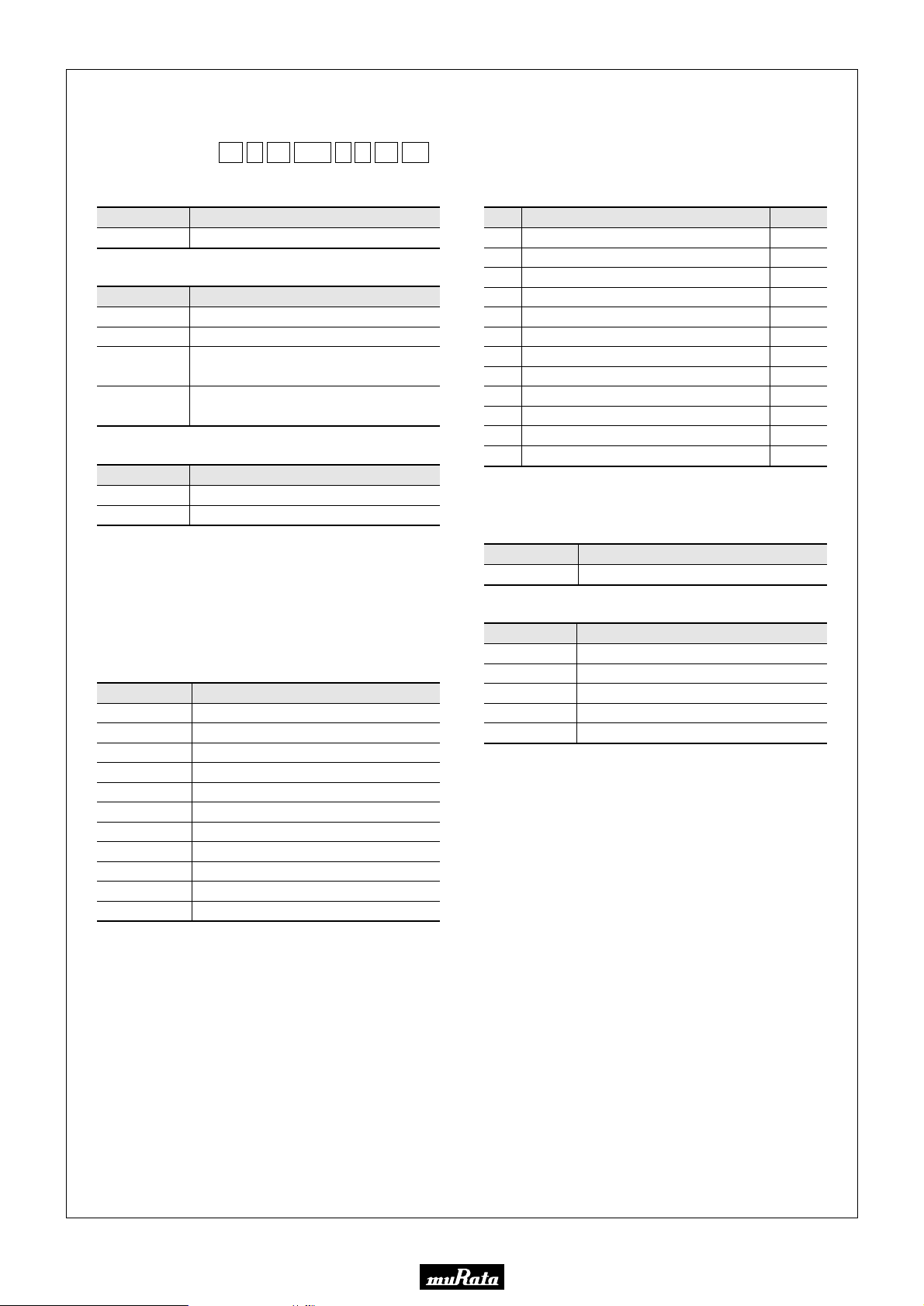
o Part Numbering
CERAFILr for FM
P50E.pdf
10.2.9
(Part Number)
SF
q
E
LF
w
e
F
10M7yA
t
r
A0
u
-B0
i
qProduct ID
Product ID
SF Ceramic Filters
wOscillation/Numbers of Element
Code
E
T
V
K
Oscillation/Numbers of Element
2 Elements Thickness Expander mode
3 Elements Thickness Expander mode
2 Elements Thickness Expander mode
(2nd Harmonic)
2 Elements Thickness Expander mode
(3rd Over Tone)
eStructure/Size
Code
Lp
Cp
is expressed "A" or subsequent code, which indicates the
p
structure/size.
Structure/Size
Lead Type
Chip Type
rNominal Center Frequency
Expressed by four-digit alphanumerics. The unit is in hertz (Hz).
Decimal point is expressed by capital letter "M" in case of MHz.
t3dB Bandwidth
Code 3dB Bandwidth
C
D
E
F
G
H
J
K
L
M
N
450kHz min
350kHz min
330kHz
280kHz
230kHz
180kHz
150kHz
110kHz
80kHz
50kHz
35kHz
yCenter Frequency/Tolerance
Code Center Frequency
Center Frequency mentioned by specification
A
-30kHz shifted from center frequency of code "A"
B
+30kHz shifted from center frequency of code "A"
C
-60kHz shifted from center frequency of code "A"
D
+60kHz shifted from center frequency of code "A"
E
Center Frequency mentioned by specification
H
-50kHz shifted from center frequency of code "H"
V
+50kHz shifted from center frequency of code "H"
W
Center Frequency mentioned by specification
K
Z
M
F
3dB band width of "F" signifies the frequency difference (both + and -)
from reference frequency which is nominal center frequency.
Combination of A, B, C, D, E
Combination of A, B, C
Nominal Center Frequency
Tolerance
±30kHz
±30kHz
±30kHz
±30kHz
±30kHz
±25kHz
±25kHz
±25kHz
±20kHz
—
—
—
uSeries
Code Series
A0
Two-digit alphanumerics express series
iPackaging
Code
-B0
-R0
-R1
-A0
-A1
Radial taping is applied to lead type and embossed taping to chip
type. With non-standard products, two-digit alphanumerics indicating
"Individual Specification" is added between "uSeries" and
"iPackaging".
1500pcs. /Radial Taping H
1000pcs. /Radial Taping H
Packaging
Bulk
Embossed Taping ø180mm
Embossed Taping ø330mm
=18mm
0
=18mm
0
2
Page 5
• This PDF catalog is downloaded from the website of Murata Manufacturing co., ltd. Therefore, it’s specifications are subject to change or our products in it may be discontinued without advance notice. Please check with our
!Note
• This PDF catalog has only typical specifications because there is no space for detailed specifications. Therefore, please approve our product specifications or transact the approval sheet for product specifications before ordering.
• Please read rating and !CAUTION (for storage, operating, rating, soldering, mounting and handling) in this catalog to prevent smoking and/or burning, etc.
!Note
sales representatives or product engineers before ordering.
• This catalog has only typical specifications because there is no space for detailed specifications. Therefore, please approve our product specifications or transact the approval sheet for product specifications before ordering.
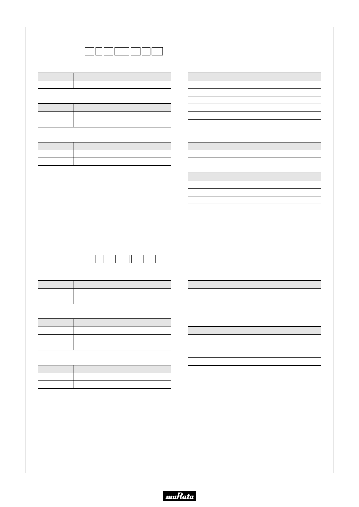
CERAFILr
P50E.pdf
10.2.9
(Part Number)
SF
q
KA
S
w
4M50
CF
e
r
t
00
y
-R1
u
qProduct ID
Product ID
SF Ceramic Filters
wOscillation/Numbers of Element
Code
S
T
Oscillation/Numbers of Element
2 Elements Thickness Shear mode
3 Elements Thickness Expander mode
eStructure/Size
Code
Rp
Kp
is expressed "A" or subsequent code, which indicates the
p
structure/size. SFT series has leaded type only.
Structure/Size
Lead Type
Chip Type
rNominal Center Frequency
Expressed by four-digit alphanumerics. The unit is in hertz (Hz).
Decimal point is expressed by capital letter "M" in case of MHz.
tProduct Specification Code (1)
Code
AF
BF
CF
DF
EF
The code AF is not applied to SFS series but to SFT series only.
Product Specification Code (1)
Standard Bandwidth Type
Tight Bandwidth Type
Standard Bandwidth Type
Broad Bandwidth Type
Ultra-broad Bandwidth Type
yProduct Specification Code (2)
Code
00
Product Specification Code (2)
Standard Type
uPackaging
Code
-B0
-A0
-R1
Radial taping is applied to lead type and embossed taping to chip
type. With non-standard products, two-digit alphanumerics indicating
"Individual Specification" is added between "yProduct Specification
Code (2)" and "uPackaging".
Embossed Taping ø=330mm
Packaging
Bulk
Radial Taping H
=18mm
0
CERAFILr for AM
(Part Number)
SF
q
P
w
e
455KtD4A
r
KA
qProduct ID
Product ID
SF
CF
Ceramic Filters
Ceramic Filters
wOscillation/Numbers of Element
Code
U
Z
P
Oscillation/Numbers of Element
1 Element Area Expansion mode
2 Elements Area Expansion mode
4 Elements Area Expansion mode
eStructure/Size
Code
Lp
Cp/Kp
p is "A" or subsequent code, which indicates the structure/size. It
varies depending on vibration mode and number of elements.
Structure/Size
Lead Type
Chip Type
rNominal Center Frequency
Expressed by four-digit alphanumerics. The unit is in hertz (Hz).
Capital letter "K" following three figures expresses the unit of
"kHz".
-B0
y
tProduct Specification
Code
D4A
A indicates standard type.
pp
Three-digit alphanumerics indicate product
specification of 3dB or 6dB frequency tolerance.
Product Specification
yPackaging
Code
-B0
-R0
-R1
Embossed Taping (ø180mm)
Embossed Taping (ø330mm)
-M0
Radial taping is applied to lead type and embossed taping to chip
type. With non-standard products, three-digit alphanumerics
indicating "Individual Specification" is added between "tProduct
Specification" and "yPackaging".
Packaging
Bulk
Magazine Cassette
3
Page 6
• This PDF catalog is downloaded from the website of Murata Manufacturing co., ltd. Therefore, it’s specifications are subject to change or our products in it may be discontinued without advance notice. Please check with our
!Note
• This PDF catalog has only typical specifications because there is no space for detailed specifications. Therefore, please approve our product specifications or transact the approval sheet for product specifications before ordering.
• Please read rating and !CAUTION (for storage, operating, rating, soldering, mounting and handling) in this catalog to prevent smoking and/or burning, etc.
!Note
sales representatives or product engineers before ordering.
• This catalog has only typical specifications because there is no space for detailed specifications. Therefore, please approve our product specifications or transact the approval sheet for product specifications before ordering.
Ceramic Traps
P50E.pdf
10.2.9
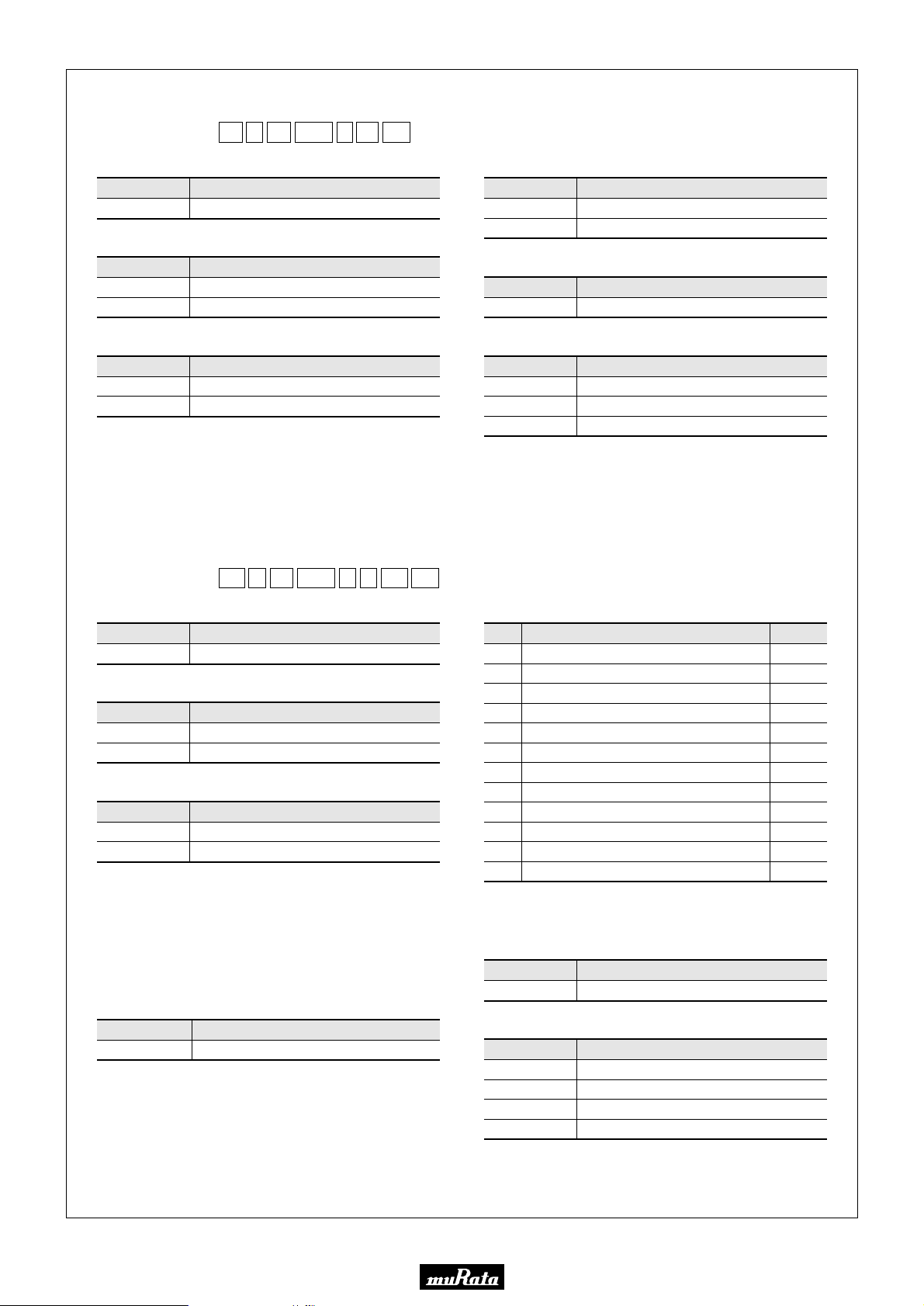
(Part Number)
TP
q
S
w
KA
e
4M00tB
r
-R0
y00u
qProduct ID
Product ID
TP Ceramic Traps
wFunction
Code
S
W
Function
Single Traps
Double Traps
eStructure/Size
Code
Rp
Kp
is expressed "A" or subsequent code, which indicates the
p
structure/size.
Structure/Size
Lead Type
Chip Type
rNominal Center Frequency
Expressed by four-digit alphanumerics. The unit is in hertz (Hz).
Decimal point is expressed by capital letter "M".
Discriminators for FM
-B0
tGy
001
A
u
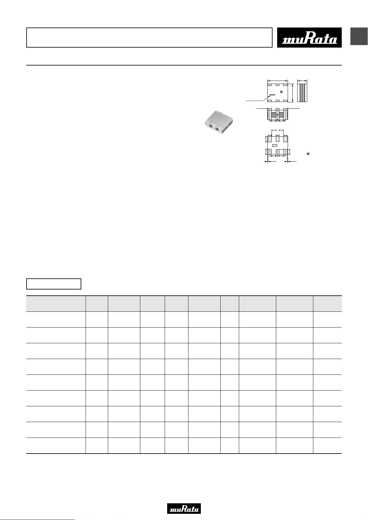
(Part Number)
CD
q
A
w
10M7
e
r
LF
qProduct ID
Product ID
CD Discriminators
wOscillation
Code
A
S
Oscillation
Thickness Expander mode
Thickness Shear mode
eStructure/Size
Code
Lp
Cp
is expressed "A" or subsequent code, which indicates the
p
structure/size.
Structure/Size
Lead Type
Chip Type
rNominal Center Frequency
Expressed by four-digit alphanumerics. The unit is in hertz (Hz).
Decimal point is expressed by capital letter "M" in case of MHz.
tSeries
Code Series
G
Two-digit alphanumerics express series
tProduct Specification Code (1)
Code
B
C
Product Specification (1)
Broad-bandwidth Type
Low-capacitance Type
yProduct Specification Code (2)
Code
00
Product Specification (2)
Standard Type
uPackaging
Code
-B0
-A0
-R1
Radial taping is applied to lead type and embossed taping to chip
type. With non-standard products, three-digit alphanumerics
indicating "Individual Specification" is added between "yProduct
Specification Code (2)" and "uPackaging".
Embossed Taping ø=330mm
Packaging
Bulk
Radial Taping H
=18mm
0
i
yCenter Frequency/Tolerance
Code Center Frequency
Center Frequency mentioned by specification
A
-30kHz shifted from center frequency of code "A"
B
+30kHz shifted from center frequency of code "A"
C
-60kHz shifted from center frequency of code "A"
D
+60kHz shifted from center frequency of code "A"
E
Center Frequency mentioned by specification
H
-50kHz shifted from center frequency of code "H"
V
+50kHz shifted from center frequency of code "H"
W
Center Frequency mentioned by specification
K
Z
M
F
3dB band width of "F" signifies the frequency difference (both + and -)
from reference frequency which is nominal center frequency.
Combination of A, B, C, D, E
Combination of A, B, C
Nominal Center Frequency
Tolerance
±30kHz
±30kHz
±30kHz
±30kHz
±30kHz
±25kHz
±25kHz
±25kHz
±20kHz
—
—
—
uIC
Code
001
Applicable IC Control Code
IC
iPackaging
Code
-B0
-A0
-R0
-R1
Radial taping is applied to lead type and embossed taping to chip
type. With non-standard products, an alphanumerics indicating
"Individual Specification" is added between "uIC" and
"iPackaging".
Embossed Taping ø=180mm
Embossed Taping ø=330mm
Packaging
Bulk
Radial Taping H
=18mm
0
4
Page 7
• This PDF catalog is downloaded from the website of Murata Manufacturing co., ltd. Therefore, it’s specifications are subject to change or our products in it may be discontinued without advance notice. Please check with our
!Note
• This PDF catalog has only typical specifications because there is no space for detailed specifications. Therefore, please approve our product specifications or transact the approval sheet for product specifications before ordering.
• Please read rating and !CAUTION (for storage, operating, rating, soldering, mounting and handling) in this catalog to prevent smoking and/or burning, etc.
!Note
sales representatives or product engineers before ordering.
• This catalog has only typical specifications because there is no space for detailed specifications. Therefore, please approve our product specifications or transact the approval sheet for product specifications before ordering.
P50E.pdf
10.2.9
CERAFILr (Filters/Traps/Discriminators) for Audio/Visual Equipment
1
CERAFILr 10.7MHz Small Chip Type SFECF Series
(0.6)
0.65±0.3
(3)
(4)
3.1±0.2
0 to 0.4
0.75±0.3
0 to 0.35
1.3±0.1
(1) : Input
(2)(5) : Ground
(3)(4) : No connect
(6) : Output
: EIAJ Monthly Code
: Reference( )
(in mm)
SFECF10M7 series for FM-receivers are small,
high performance and super thin (1.4mm max.) filters.
Piezoelectric element is connected in the sandwich
shape by ceramics substrate.
They have 1.4mm max. thickness and small mounting area.
(3.45x3.1mm)
SFECF series and CDSCB series (MHz Discriminator)
enable customers to make VICS/RKE/TPMS set so thin and
small sized.
■ Features
1. The filters are mountable by automatic placers.
2. They are slim, at only 1.4mm max. thickness, and
have a small mounting area (3.45x3.1mm) enabling
flexible PCB design.
3. Various bandwidths are available. Select a
suitable type in accordance with the desired
selectivity.
4. Operating Temperature Range:
-20 to +80 (degrees C)(Standard Type)
-40 to +85 (degrees C)(High-reliability Type)
Storage Temperature Range:
-40 to +85 (degrees C)(Standard Type)
-55 to +85 (degrees C)(High-reliability Type)
Input electrode
marker
0 to 0.4
0.65±0.3
(0.6)(0.6)
(1.28)
(1)
0.85±0.3
(6)
(1.28)(1.28)
0.85±0.3
0 to 0.35
3.45±0.2
(1.28)
0.3 min.0.3 min.
0.7±0.3
(2)
(5)
Standard Type
Part Number
SFECF10M7HA00-R0
Center
Frequency
(fo) (MHz)
10.700
±30kHz
SFECF10M7HF00-R0
SFECF10M7GA00-R0
10.700
±30kHz
SFECF10M7GF00-R0
SFECF10M7FA00-R0
10.700
±30kHz
SFECF10M7FF00-R0
SFECF10M7EA00-R0
SFECF10M7DA0001-R0
10.700
±30kHz
10.700
±30kHz
SFECF10M7DF00-R0
Area of Attenuation: [within 20dB]
Area of Insertion Loss: at minimum loss point Area of Ripple: within 3dB B.W.
Center frequency (fo) defined by the center of 3dB bandwidth.
For safety purposes, connect the output of filters to the IF amplifier through a D.C. blocking capacitor. Avoid applying a direct current to the output of ceramic filters.
The order quantity should be an integral multiple of the "Minimum Quantity" shown in the package page.
Nominal Center
Frequency (fn)
(MHz)
3dB
Bandwidth
(kHz)
Attenuation
(kHz)
- 180 ±40kHz 470 max. 4.0 ±2.0dB 1.0 max.
- 10.700 fn±25 min. 510 max.
- 230 ±50kHz 510 max. 3.5 ±2.0dB 1.0 max.
- 10.700 fn±45 min. 560 max.
- 280 ±50kHz 590 max. 3.0 ±2.0dB 1.0 max.
- 10.700 fn±65 min. 620 max.
- 330 ±50kHz 700 max. 3.0 ±2.0dB 1.0 max.
- 420 min. 950 max. 3.0 ±2.0dB 3.0 max.
- 10.700 fn±150 min. 990 max.
Insertion Loss
(dB)
8.0 max.
[at fn]
8.0 max.
[at fn]
7.0 max.
[at fn]
6.0 max.
[at fn]
Ripple
(dB)
1.0 max.
1.0 max.
1.0 max.
3.0 max.
Spurious
Attenuation
(1) (dB)
30 min.
[within 9MHz to fo]
30 min.
[within 9MHz to fn]
30 min.
[within 9MHz to fo]
30 min.
[within 9MHz to fn]
30 min.
[within 9MHz to fo]
30 min.
[within 9MHz to fn]
30 min.
[within 9MHz to fo]
35 min.
[within 9MHz to fo]
20 min.
[within 9MHz to fn]
Spurious
Attenuation
(2) (dB)
30 min.
[within fo to 12MHz]
25 min.
[within fn to 12MHz]
30 min.
[within fo to 12MHz]
25 min.
[within fn to 12MHz]
30 min.
[within fo to 12MHz]
25 min.
[within fn to 12MHz]
30 min.
[within fo to 12MHz]
25 min.
[within fo to 12MHz]
20 min.
[within fn to 12MHz]
Input/Output
Impedance
(ohm)
330
330
330
330
330
330
330
330
330
5
Page 8
• This PDF catalog is downloaded from the website of Murata Manufacturing co., ltd. Therefore, it’s specifications are subject to change or our products in it may be discontinued without advance notice. Please check with our
!Note
• This PDF catalog has only typical specifications because there is no space for detailed specifications. Therefore, please approve our product specifications or transact the approval sheet for product specifications before ordering.
• Please read rating and !CAUTION (for storage, operating, rating, soldering, mounting and handling) in this catalog to prevent smoking and/or burning, etc.
!Note
sales representatives or product engineers before ordering.
• This catalog has only typical specifications because there is no space for detailed specifications. Therefore, please approve our product specifications or transact the approval sheet for product specifications before ordering.
P50E.pdf
10.2.9
1
High-reliability Type
Part Number
SFECF10M7HA00S0-R0
Center
Frequency
(fo) (MHz)
10.700
±30kHz
SFECF10M7HF00S0-R0
SFECF10M7GA00S0-R0
10.700
±30kHz
SFECF10M7GF00S0-R0
SFECF10M7FA00S0-R0
10.700
±30kHz
SFECF10M7FF00S0-R0
SFECF10M7EA00S0-R0
10.700
±30kHz
SFECF10M7DF00S0-R0
Area of Attenuation: [within 20dB]
Area of Insertion Loss: at minimum loss point Area of Ripple: within 3dB B.W.
Center frequency (fo) defined by the center of 3dB bandwidth.
For safety purposes, connect the output of filters to the IF amplifier through a D.C. blocking capacitor. Avoid applying a direct current to the output of ceramic filters.
The order quantity should be an integral multiple of the "Minimum Quantity" shown in the package page.
Nominal Center
Frequency (fn)
(MHz)
3dB
Bandwidth
(kHz)
Attenuation
(kHz)
- 180 ±40kHz 470 max. 4.0 ±2.0dB 1.0 max.
- 10.700 fn±25 min. 510 max.
- 230 ±50kHz 510 max. 3.5 ±2.0dB 1.0 max.
- 10.700 fn±45 min. 560 max.
- 280 ±50kHz 590 max. 3.0 ±2.0dB 1.0 max.
- 10.700 fn±65 min. 630 max.
- 330 ±50kHz 700 max. 3.0 ±2.0dB 1.0 max.
- 10.700 fn±145 min. 990 max.
Insertion Loss
(dB)
8.0 max.
[at fn]
8.0 max.
[at fn]
7.0 max.
[at fn]
6.0 max.
[at fn]
Ripple
(dB)
1.0 max.
1.0 max.
1.0 max.
3.0 max.
Spurious
Attenuation
(1) (dB)
30 min.
[within 9MHz to fo]
30 min.
[within 9MHz to fn]
30 min.
[within 9MHz to fo]
30 min.
[within 9MHz to fn]
30 min.
[within 9MHz to fo]
30 min.
[within 9MHz to fn]
30 min.
[within 9MHz to fo]
20 min.
[within 9MHz to fn]
Spurious
Attenuation
(2) (dB)
30 min.
[within fo to 12MHz]
25 min.
[within fn to 12MHz]
30 min.
[within fo to 12MHz]
25 min.
[within fn to 12MHz]
30 min.
[within fo to 12MHz]
25 min.
[within fn to 12MHz]
30 min.
[within fo to 12MHz]
20 min.
[within fn to 12MHz]
Input/Output
Impedance
(ohm)
330
330
330
330
330
330
330
330
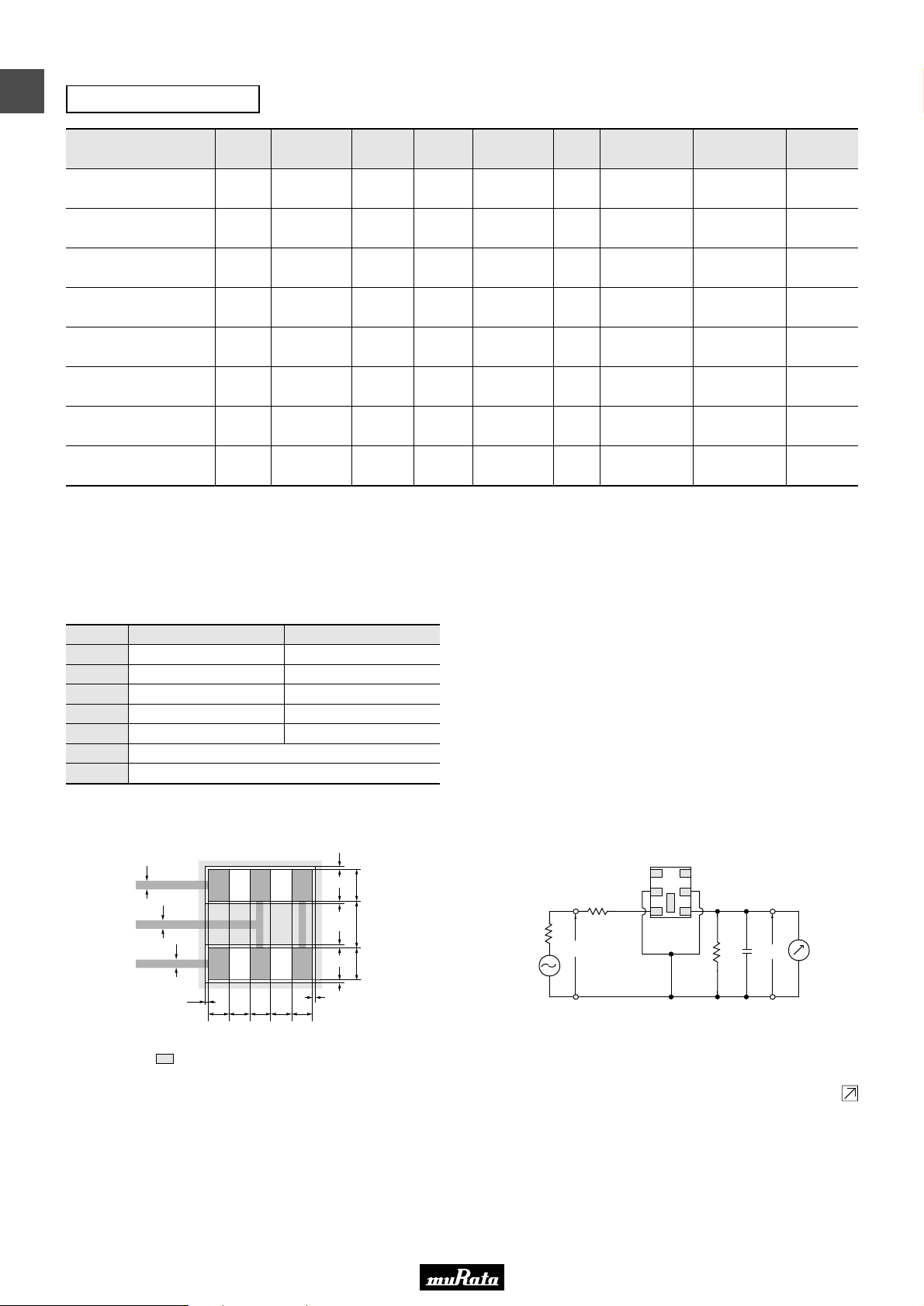
■ Standard Center Frequency Rank Code
CODE
D
B
A
C
E
Z
M
30kHz Step
10.64MHz±30kHz
10.67MHz±30kHz
10.70MHz±30kHz
10.73MHz±30kHz
10.76MHz±30kHz
Combination A, B, C, D, E
Combination A, B, C
25kHz Step
10.650MHz±25kHz
10.675MHz±25kHz
10.700MHz±25kHz
10.725MHz±25kHz
10.750MHz±25kHz
■ Standard Land Pattern Dimensions
0.3
0.3
0.3
0.1
0.8 0.6 0.8 0.6 0.8
It shows solder resist land pattern.
(6) (5) (4)
(1) (2) (3)
0.10.10.10.1
0.1
1.051.401.05
(1) :
(2)(5) :
(3)(4) :
(6) :
Input
Ground
No connect
Output
(in mm)
■ Test Circuit
(3)
(2)
R
1
Rg
E1
S.S.G.
Rg = 50Ω R
C2 = 10 ± 2 pF (Including stray capacitance and Input capacitance
of RF Volt Meter)
E1 : S.S.G. Output Voltage
1 = 280Ω ±5% R2 = 330Ω ±5%
(1)
(4)
(5)
(6)
C2
R
2
RF
E2
Voltmeter
Input
(1) :
Ground
(2)(5) :
No connect
(3)(4) :
Output
(6) :
Continued on the following page.
6
Page 9
• This PDF catalog is downloaded from the website of Murata Manufacturing co., ltd. Therefore, it’s specifications are subject to change or our products in it may be discontinued without advance notice. Please check with our
!Note
• This PDF catalog has only typical specifications because there is no space for detailed specifications. Therefore, please approve our product specifications or transact the approval sheet for product specifications before ordering.
• Please read rating and !CAUTION (for storage, operating, rating, soldering, mounting and handling) in this catalog to prevent smoking and/or burning, etc.
!Note
sales representatives or product engineers before ordering.
• This catalog has only typical specifications because there is no space for detailed specifications. Therefore, please approve our product specifications or transact the approval sheet for product specifications before ordering.
Continued from the preceding page.
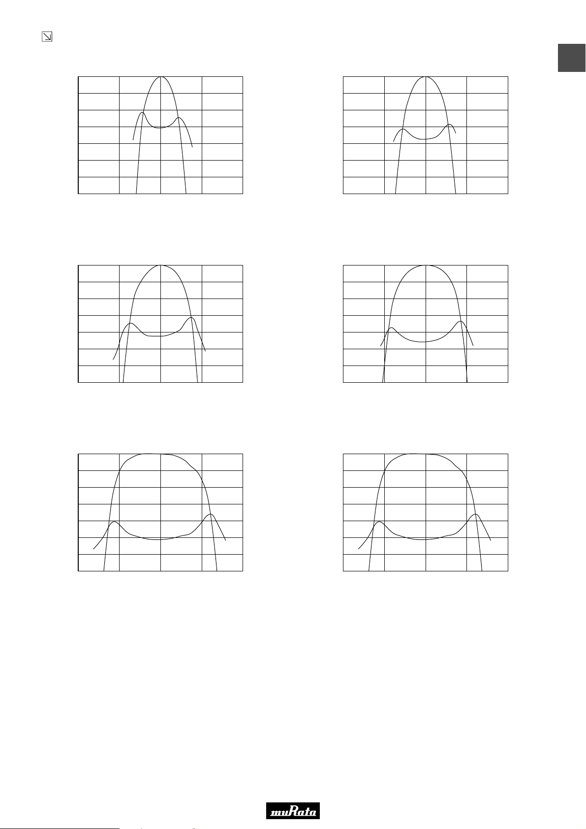
■ Frequency Characteristics Standard Type
SFECF10M7HA00-R0/SFECF10M7HF00-R0
0
1
2
3
4
Attenuation (dB)
5
6
7
10.300 10.500 10.700 10.900 11.100
Frequency (MHz)
7.0
6.0
5.0
4.0
3.0
G.D.T. (µsec.)
2.0
1.0
0.0
SFECF10M7GA00-R0/SFECF10M7GF00-R0
0
1
2
3
4
Attenuation (dB)
5
6
7
10.300 10.500 10.700 10.900 11.100
Frequency (MHz)
7.0
6.0
5.0
4.0
3.0
2.0
1.0
0.0
P50E.pdf
10.2.9
1
G.D.T. (µsec.)
SFECF10M7FA00-R0/SFECF10M7FF00-R0
0
1
2
3
4
Attenuation (dB)
5
6
7
10.300 10.500 10.700 10.900 11.100
Frequency (MHz)
SFECF10M7DA0001-R0
0
1
2
3
4
Attenuation (dB)
5
6
7
10.300 10.500 10.700 10.900 11.100
Frequency (MHz)
SFECF10M7EA00-R0
7.0
6.0
5.0
4.0
3.0
G.D.T. (µsec.)
2.0
1.0
0.0
0
1
2
3
4
Attenuation (dB)
5
6
7
10.300 10.500 10.700 10.900 11.100
Frequency (MHz)
7.0
6.0
5.0
4.0
3.0
G.D.T. (µsec.)
2.0
1.0
0.0
SFECF10M7DF00-R0
7.0
6.0
5.0
4.0
3.0
G.D.T. (µsec.)
2.0
1.0
0.0
0
1
2
3
4
Attenuation (dB)
5
6
7
10.300 10.500 10.700 10.900 11.100
Frequency (MHz)
7.0
6.0
5.0
4.0
3.0
G.D.T. (µsec.)
2.0
1.0
0.0
7
Page 10
• This PDF catalog is downloaded from the website of Murata Manufacturing co., ltd. Therefore, it’s specifications are subject to change or our products in it may be discontinued without advance notice. Please check with our
!Note
• This PDF catalog has only typical specifications because there is no space for detailed specifications. Therefore, please approve our product specifications or transact the approval sheet for product specifications before ordering.
• Please read rating and !CAUTION (for storage, operating, rating, soldering, mounting and handling) in this catalog to prevent smoking and/or burning, etc.
!Note
sales representatives or product engineers before ordering.
• This catalog has only typical specifications because there is no space for detailed specifications. Therefore, please approve our product specifications or transact the approval sheet for product specifications before ordering.
P50E.pdf
10.2.9
1
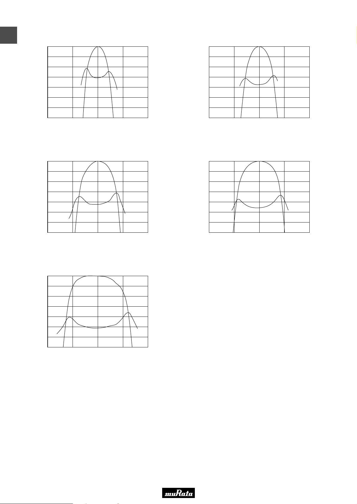
SFECF10M7HA00S0-R0/SFECF10M7HF00S0-R0
0
1
2
3
4
Attenuation (dB)
5
6
7
10.300 10.500 10.700 10.900 11.100
Frequency (MHz)
SFECF10M7FA00S0-R0/SFECF10M7FF00S0-R0
0
1
2
3
4
Attenuation (dB)
5
6
7
10.300 10.500 10.700 10.900 11.100
Frequency (MHz)
SFECF10M7GA00S0-R0/SFECF10M7GF00S0-R0
7.0
6.0
5.0
4.0
3.0
G.D.T. (µsec.)
2.0
1.0
0.0
0
1
2
3
4
Attenuation (dB)
5
6
7
10.300 10.500 10.700 10.900 11.100
Frequency (MHz)
7.0
6.0
5.0
4.0
3.0
G.D.T. (µsec.)
2.0
1.0
0.0
SFECF10M7EA00S0-R0
7.0
6.0
5.0
4.0
3.0
G.D.T. (µsec.)
2.0
1.0
0.0
0
1
2
3
4
Attenuation (dB)
5
6
7
10.300 10.500 10.700 10.900 11.100
Frequency (MHz)
7.0
6.0
5.0
4.0
3.0
G.D.T. (µsec.)
2.0
1.0
0.0
■ Frequency Characteristics High-reliability Type
SFECF10M7DF00S0-R0
0
1
2
3
4
Attenuation (dB)
5
6
7
10.300 10.500 10.700 10.900 11.100
Frequency (MHz)
7.0
6.0
5.0
4.0
3.0
G.D.T. (µsec.)
2.0
1.0
0.0
8
Page 11
• This PDF catalog is downloaded from the website of Murata Manufacturing co., ltd. Therefore, it’s specifications are subject to change or our products in it may be discontinued without advance notice. Please check with our
!Note
• This PDF catalog has only typical specifications because there is no space for detailed specifications. Therefore, please approve our product specifications or transact the approval sheet for product specifications before ordering.
• Please read rating and !CAUTION (for storage, operating, rating, soldering, mounting and handling) in this catalog to prevent smoking and/or burning, etc.
!Note
sales representatives or product engineers before ordering.
• This catalog has only typical specifications because there is no space for detailed specifications. Therefore, please approve our product specifications or transact the approval sheet for product specifications before ordering.
P50E.pdf
10.2.9
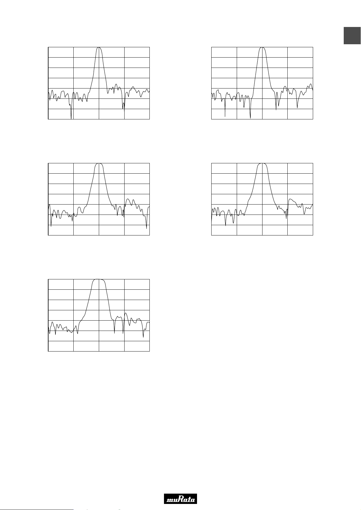
■ Frequency Characteristics (Spurious) Standard Type
SFECF10M7HA00-R0/SFECF10M7HF00-R0
0
10
20
30
40
Attenuation (dB)
50
60
70
8.700 9.700 10.700 11.700 12.700
SFECF10M7FA00-R0/SFECF10M7FF00-R0
0
10
20
30
40
Attenuation (dB)
50
60
70
8.700 9.700 10.700 11.700 12.700
Frequency (MHz)
Frequency (MHz)
SFECF10M7GA00-R0/SFECF10M7GF00-R0
0
10
20
30
40
Attenuation (dB)
50
60
70
8.700 9.700 10.700 11.700 12.700
Frequency (MHz)
SFECF10M7EA00-R0
0
10
20
30
40
Attenuation (dB)
50
60
70
8.700 9.700 10.700 11.700 12.700
Frequency (MHz)
1
SFECF10M7DA0001-R0/SFECF10M7DF00-R0
0
10
20
30
40
Attenuation (dB)
50
60
70
8.700 9.700 10.700 11.700 12.700
Frequency (MHz)
9
Page 12
• This PDF catalog is downloaded from the website of Murata Manufacturing co., ltd. Therefore, it’s specifications are subject to change or our products in it may be discontinued without advance notice. Please check with our
!Note
• This PDF catalog has only typical specifications because there is no space for detailed specifications. Therefore, please approve our product specifications or transact the approval sheet for product specifications before ordering.
• Please read rating and !CAUTION (for storage, operating, rating, soldering, mounting and handling) in this catalog to prevent smoking and/or burning, etc.
!Note
sales representatives or product engineers before ordering.
• This catalog has only typical specifications because there is no space for detailed specifications. Therefore, please approve our product specifications or transact the approval sheet for product specifications before ordering.
P50E.pdf
10.2.9
1
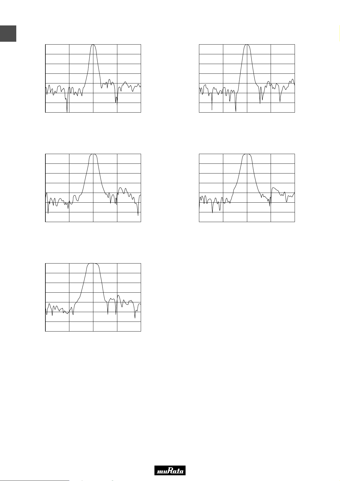
SFECF10M7HA00S0-R0/SFECF10M7HF00S0-R0
0
10
20
30
40
Attenuation (dB)
50
60
70
8.700 9.700 10.700 11.700 12.700
Frequency (MHz)
SFECF10M7FA00S0-R0/SFECF10M7FF00S0-R0
0
10
20
30
40
Attenuation (dB)
50
60
70
8.700 9.700 10.700 11.700 12.700
Frequency (MHz)
SFECF10M7GA00S0-R0/SFECF10M7GF00S0-R0
0
10
20
30
40
Attenuation (dB)
50
60
70
8.700 9.700 10.700 11.700 12.700
Frequency (MHz)
SFECF10M7EA00S0-R0
0
10
20
30
40
Attenuation (dB)
50
60
70
8.700 9.700 10.700 11.700 12.700
Frequency (MHz)
■ Frequency Characteristics (Spurious) High-reliability Type
SFECF10M7DF00S0-R0
0
10
20
30
40
Attenuation (dB)
50
60
70
8.700 9.700 10.700 11.700 12.700
Frequency (MHz)
10
Page 13
• This PDF catalog is downloaded from the website of Murata Manufacturing co., ltd. Therefore, it’s specifications are subject to change or our products in it may be discontinued without advance notice. Please check with our
!Note
• This PDF catalog has only typical specifications because there is no space for detailed specifications. Therefore, please approve our product specifications or transact the approval sheet for product specifications before ordering.
• Please read rating and !CAUTION (for storage, operating, rating, soldering, mounting and handling) in this catalog to prevent smoking and/or burning, etc.
!Note
sales representatives or product engineers before ordering.
• This catalog has only typical specifications because there is no space for detailed specifications. Therefore, please approve our product specifications or transact the approval sheet for product specifications before ordering.
CERAFILr (Filters/Traps/Discriminators) for Audio/Visual Equipment
P50E.pdf
10.2.9
CERAFILr 10.7MHz Chip Type SFECV/SFECK Series
SFECV/SFECK10M7 series for FM-receivers are monolithic
type ceramic filters which utilize the thickness expander
mode of the piezoelectric ceramic. SFECV series enable
customers to make AM/FM set so thin, and it can be of
help to the total chip circuit.
■ Features
1. Piezoelectric element is connected in the sandwich
shape by heat resistant substrate, thus it has
excellent mechanical strength, and it is
suitable for automatic mounting.
2. Various bandwidths are available. Select a suitable
type in accordance with the desired selectivity.
3. Operationg Temparature Range:
-20 to +80 (degrees C)(Standard Type)
-40 to +85 (degrees C)(High-reliability Type)
Storage Temparature Range:
-40 to +85 (degrees C)(Standard Type)
-55 to +85 (degrees C)(High-reliability Type)
** : EIAJ Monthly Code
** : Center Frequency Rank Code
6.9±0.3
4.05±0.4
1.2±0.5
2.9±0.31.5±0.2
(3) (2) (1)
1.0±0.5 1.0±0.5
1.2±0.3
*
*
*
1.0±0.5
1.2±0.5
1.5±0.2
: Marking
(1) : Input
(2) : Ground
(3) : Output
(in mm)
2
■ Applications
1. Small, thin radios
2. Automotive radios
3. Headphone stereos
Standard Type
Part Number
SFECV15M0EQ0001-R0
SFECV10M7KA00-R0
SFECV10M7JA00-R0
Area of Attenuation: [within 20dB]
Area of Insertion Loss: at minimum loss point
Center frequency (fo) defined by the center of 3dB bandwidth.
For safety purposes, connect the output of filters to the IF amplifier through a D.C. blocking capacitor. Avoid applying a direct current to the output of ceramic filters.
The order quantity should be an integral multiple of the "Minimum Quantity" shown in the package page.
Center
Frequency
(fo) (MHz)
15.000
±50kHz
10.700
±30kHz
10.700
±30kHz
3dB
Bandwidth
(kHz)
Attenuation
(kHz)
Insertion Loss
(dB)
Ripple
(dB)
300 min. 750 max. 7.0 max. 1.0 max.
110 ±30kHz 320 max. 6.0 ±2.0dB 1.0 max.
150 ±40kHz 380 max. 5.5 ±2.0dB 1.0 max.
Spurious
Attenuation
(1) (dB)
30 min.
[within 14MHz to fo]
35 min.
[within 9MHz to fo]
35 min.
[within 9MHz to fo]
Spurious
Attenuation
(2) (dB)
30 min.
[within fo to 16MHz]
35 min.
[within fo to 12MHz]
35 min.
[within fo to 12MHz]
High-reliability Type
Input/Output
Impedance
(ohm)
330
330
330
Part Number
SFECK10M7KA00S0-R0
SFECK10M7JA00S0-R0
Area of Attenuation: [within 20dB]
Area of Insertion Loss: at minimum loss point
Center frequency (fo) defined by the center of 3dB bandwidth.
For safety purposes, connect the output of filters to the IF amplifier through a D.C. blocking capacitor. Avoid applying a direct current to the output of ceramic filters.
The order quantity should be an integral multiple of the "Minimum Quantity" shown in the package page.
Center
Frequency
(fo) (MHz)
10.700
±30kHz
10.700
±30kHz
3dB
Bandwidth
(kHz)
Attenuation
(kHz)
Insertion Loss
(dB)
Ripple
(dB)
110 ±30kHz 320 max. 6.0 ±2.0dB 1.0 max.
150 ±40kHz 380 max. 5.5 ±2.0dB 1.0 max.
Spurious
Attenuation
(1) (dB)
35 min.
[within 9MHz to fo]
35 min.
[within 9MHz to fo]
Spurious
Attenuation
(2) (dB)
35 min.
[within fo to 12MHz]
35 min.
[within fo to 12MHz]
Input/Output
Impedance
(ohm)
330
330
11
Page 14
• This PDF catalog is downloaded from the website of Murata Manufacturing co., ltd. Therefore, it’s specifications are subject to change or our products in it may be discontinued without advance notice. Please check with our
!Note
• This PDF catalog has only typical specifications because there is no space for detailed specifications. Therefore, please approve our product specifications or transact the approval sheet for product specifications before ordering.
• Please read rating and !CAUTION (for storage, operating, rating, soldering, mounting and handling) in this catalog to prevent smoking and/or burning, etc.
!Note
sales representatives or product engineers before ordering.
• This catalog has only typical specifications because there is no space for detailed specifications. Therefore, please approve our product specifications or transact the approval sheet for product specifications before ordering.
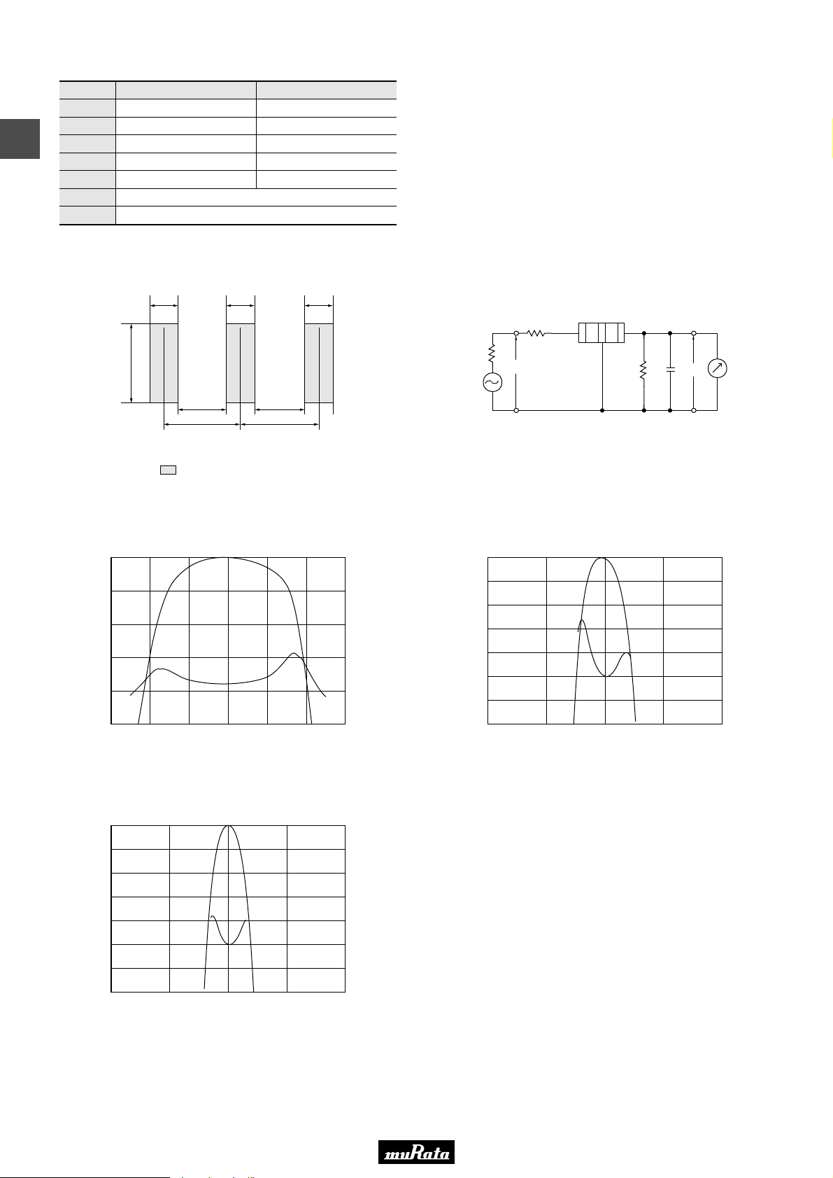
■ Standard Center Frequency Rank Code
CODE
D
B
2
A
C
E
Z
M
30kHz Step
10.64MHz±30kHz
10.67MHz±30kHz
10.70MHz±30kHz
10.73MHz±30kHz
10.76MHz±30kHz
Combination A, B, C, D, E
Combination A, B, C
25kHz Step
10.650MHz±25kHz
10.675MHz±25kHz
10.700MHz±25kHz
10.725MHz±25kHz
10.750MHz±25kHz
P50E.pdf
10.2.9
■ Standard Land Pattern Dimensions
1.2
4.0
Land
1.2 1.2
1.65
2.85 2.85
1.65
■ Frequency Characteristics Standard Type
SFECV15M0EQ0001-R0
0
2
4
6
Attenuation (dB)
8
10
14.700 14.800 14.900 15.000 15.100 15.200 15.300
Frequency (MHz)
10.0
8.0
6.0
4.0
2.0
0.0
(in mm)
G.D.T. (µsec.)
■ Test Circuit
R
1
(1)
Rg
S.S.G.
=-10dBm
E1
Rg = 50Ω R
C2 = 10 ± 2 pF (Including stray capacitance and Input capacitance
of RF Volt Meter)
E1 : S.S.G. Output Voltage
1 = 280Ω ±5% R2 = 330Ω ±5%
SFECV10M7KA00-R0
0
1
2
3
4
Attenuation (dB)
5
6
7
10.300 10.500 10.700 10.900 11.100
Frequency (MHz)
(3)
(2)
2
R
C2
RF
E2
Voltmeter
(1) : Input
(2) : Ground
(3) : Output
7.0
6.5
6.0
5.5
5.0
G.D.T. (µsec.)
4.5
4.0
3.5
SFECV10M7JA00-R0
0
1
2
3
4
Attenuation (dB)
5
6
7
10.300 10.500 10.700 10.900 11.100
Frequency (MHz)
12
8.0
7.5
7.0
6.5
6.0
G.D.T. (µsec.)
5.5
5.0
4.5
Page 15
• This PDF catalog is downloaded from the website of Murata Manufacturing co., ltd. Therefore, it’s specifications are subject to change or our products in it may be discontinued without advance notice. Please check with our
!Note
• This PDF catalog has only typical specifications because there is no space for detailed specifications. Therefore, please approve our product specifications or transact the approval sheet for product specifications before ordering.
• Please read rating and !CAUTION (for storage, operating, rating, soldering, mounting and handling) in this catalog to prevent smoking and/or burning, etc.
!Note
sales representatives or product engineers before ordering.
• This catalog has only typical specifications because there is no space for detailed specifications. Therefore, please approve our product specifications or transact the approval sheet for product specifications before ordering.
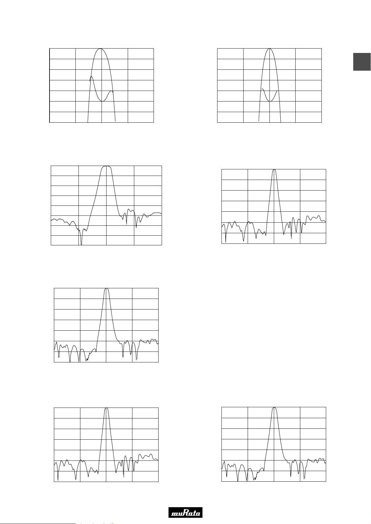
■ Frequency Characteristics High-reliability Type
SFECK10M7KA00S0-R0
0
1
2
3
4
Attenuation (dB)
5
6
7
10.300 10.500 10.700 10.900 11.100
Frequency (MHz)
7.0
6.5
6.0
5.5
5.0
G.D.T. (µsec.)
4.5
4.0
3.5
0
1
2
3
4
Attenuation (dB)
5
6
7
10.300 10.500 10.700 10.900 11.100
SFECK10M7JA00S0-R0
Frequency (MHz)
■ Frequency Characteristics (Spurious) Standard Type
0
SFECV15M0EQ0001-R0
10
20
30
40
Attenuation (dB)
50
60
70
80
13.000 15.00014.000 16.000 17.000
Frequency (MHz)
Attenuation (dB)
0
10
20
30
40
50
60
70
8.700
SFECV10M7KA00-R0
9.700 10.700
Frequency (MHz)
11.700 12.700
8.0
7.5
7.0
6.5
6.0
5.5
5.0
4.5
P50E.pdf
10.2.9
2
G.D.T. (µsec.)
SFECV10M7JA00-R0
0
10
20
30
40
Attenuation (dB)
50
60
70
8.700
9.700 10.700
Frequency (MHz)
11.700 12.700
■ Frequency Characteristics (Spurious) High-reliability Type
SFECK10M7KA00S0-R0
0
10
20
30
40
Attenuation (dB)
50
60
70
8.700
9.700 10.700
Frequency (MHz)
11.700 12.700
Attenuation (dB)
0
10
20
30
40
50
60
70
8.700
SFECK10M7JA00S0-R0
9.700 10.700
Frequency (MHz)
11.700 12.700
13
Page 16
• This PDF catalog is downloaded from the website of Murata Manufacturing co., ltd. Therefore, it’s specifications are subject to change or our products in it may be discontinued without advance notice. Please check with our
!Note
• This PDF catalog has only typical specifications because there is no space for detailed specifications. Therefore, please approve our product specifications or transact the approval sheet for product specifications before ordering.
• Please read rating and !CAUTION (for storage, operating, rating, soldering, mounting and handling) in this catalog to prevent smoking and/or burning, etc.
!Note
sales representatives or product engineers before ordering.
• This catalog has only typical specifications because there is no space for detailed specifications. Therefore, please approve our product specifications or transact the approval sheet for product specifications before ordering.
CERAFILr (Filters/Traps/Discriminators) for Audio/Visual Equipment
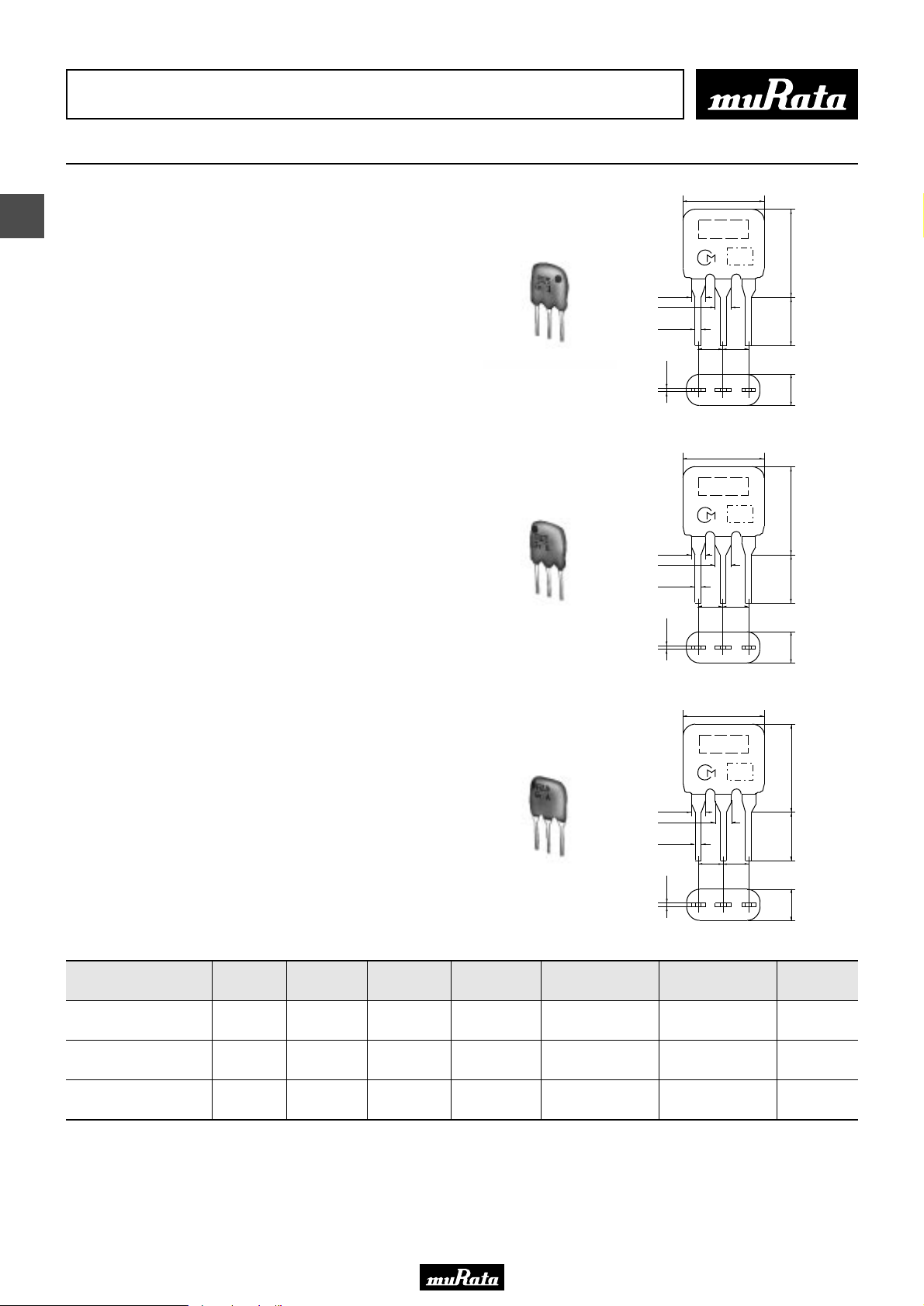
CERAFILr 10.7MHz Standard Lead Type
7.0±2.0
3
SFELF10M7 series for FM-receivers are monolithic type
ceramic filters which use the thickness expander mode
of the piezoelectric ceramic.
As part of the environment protection activity, solder
for terminal plating and terminal-element connection
inside of ceramic filter contain no lead (Pb).
■ Features
1. These miniature filters have high mechanical
strength.
2. Low loss, favorable waveform symmetry, and high
selectivity
3. Various band widths are available for applications
in wide to narrow bands.
4. Small dispersion and stable characteristics
5. Change in center frequency is typically within
+-30ppm/(degrees C) at -20 to +80 (degrees C).
6. High reliability
SFELF10M7HA00-B0
SFELF10M7GA00-B0
1.38±0.2
1.7±0.1
0.5±0.1
0.3±0.1
1.38±0.2
1.7±0.1
0.5±0.1
0.3±0.1
M A R K I N G
2.5±0.2
(3)
(2)
7.0±2.0
M A R K I N G
2.5±0.2
(3)
(2)
E I A J
C O D E
2.5±0.2
E I A J
C O D E
2.5±0.2
(1)
(1)
7.0±2.0
5.0±1.0
3.0±1.0
7.0±2.0
5.0±1.0
3.0±1.0
(1) : Input
(2) : Ground
(3) : Output
(in mm)
(1) : Input
(2) : Ground
(3) : Output
(in mm)
P50E.pdf
10.2.9
7.0±2.0
M A R K I N G
E I A J
C O D E
1.38±0.2
1.7±0.1
0.5±0.1
2.5±0.2
2.5±0.2
SFELF10M7FA00-B0
Part Number
SFELF10M7HA00-B0
SFELF10M7GA00-B0
SFELF10M7FA00-B0
Area of Attenuation: [within 20dB]
Area of Insertion Loss: at minimum loss point
Center frequency (fo) defined by the center of 3dB bandwidth.
For safety purposes, connect the output of filters to the IF amplifier through a D.C. blocking capacitor. Avoid applying a direct current to the output of ceramic filters.
The order quantity should be an integral multiple of the "Minimum Quantity" shown in the package page.
Center
Frequency
(fo) (MHz)
10.700
±30kHz
10.700
±30kHz
10.700
±30kHz
3dB
Bandwidth
(kHz)
Attenuation
(kHz)
Insertion Loss
(dB)
180 ±40kHz 520 max. 7.0 max.
230 ±50kHz 570 max. 4.0 ±2.0dB
280 ±50kHz 650 max. 4.0 ±2.0dB
Spurious
Attenuation
(1) (dB)
40 min.
[within 9MHz to fo]
40 min.
[within 9MHz to fo]
30 min.
[within 9MHz to fo]
0.3±0.1
(3)
(2)
Spurious
Attenuation
(2) (dB)
40 min.
[within fo to 12MHz]
40 min.
[within fo to 12MHz]
30 min.
[within fo to 12MHz]
(1)
7.0±2.0
5.0±1.0
3.0±1.0
Input/Output
Impedance
(1) : Input
(2) : Ground
(3) : Output
(in mm)
(ohm)
330
330
330
14
Page 17
• This PDF catalog is downloaded from the website of Murata Manufacturing co., ltd. Therefore, it’s specifications are subject to change or our products in it may be discontinued without advance notice. Please check with our
!Note
• This PDF catalog has only typical specifications because there is no space for detailed specifications. Therefore, please approve our product specifications or transact the approval sheet for product specifications before ordering.
• Please read rating and !CAUTION (for storage, operating, rating, soldering, mounting and handling) in this catalog to prevent smoking and/or burning, etc.
!Note
sales representatives or product engineers before ordering.
• This catalog has only typical specifications because there is no space for detailed specifications. Therefore, please approve our product specifications or transact the approval sheet for product specifications before ordering.
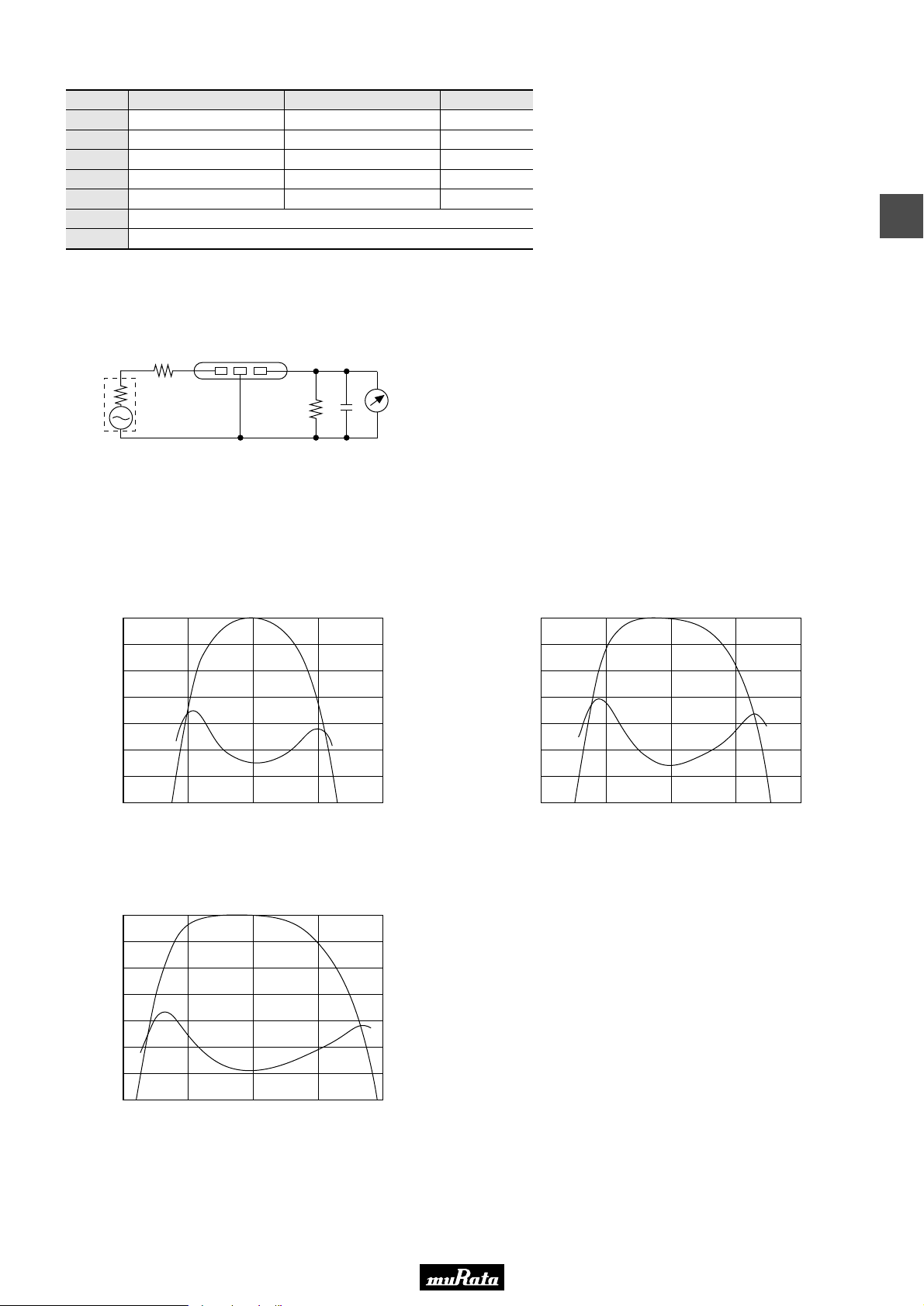
■ Standard Center Frequency Rank Code
CODE
D
B
A
C
E
Z
M
30kHz Step
10.64MHz±30kHz
10.67MHz±30kHz
10.70MHz±30kHz
10.73MHz±30kHz
10.76MHz±30kHz
25kHz Step
10.650MHz±25kHz
10.675MHz±25kHz
10.700MHz±25kHz
10.725MHz±25kHz
10.750MHz±25kHz
Combination A, B, C, D, E
Combination A, B, C
Color Code
Black
Blue
Red
Orange
White
■ Test Circuit
P50E.pdf
10.2.9
3
(1) (2) (3)
S.S.G
1
R
Rg
Rg + R1 = R2 = Input and Output Impedance
C = 10pF (Including stray capacitance and input
capacitance of RF voltmeter.)
■ Frequency Characteristics
SFELF10M7HA00-B0
0
1
2
3
4
Attenuation (dB)
5
6
7
10.500 10.600 10.700 10.800 10.900
Frequency (MHz)
RF
C
R2
Voltmeter
(1) : Input
(2) : Ground
(3) : Output
SFELF10M7GA00-B0
6.5
6.0
5.5
5.0
4.5
G.D.T. (µsec.)
4.0
3.5
3.0
0
1
2
3
4
Attenuation (dB)
5
6
7
10.500 10.600 10.700 10.800 10.900
Frequency (MHz)
6.0
5.5
5.0
4.5
4.0
G.D.T. (µsec.)
3.5
3.0
2.5
SFELF10M7FA00-B0
0
1
2
3
4
Attenuation (dB)
5
6
7
10.500 10.600 10.700 10.800 10.900
Frequency (MHz)
5.5
5.0
4.5
4.0
3.5
G.D.T. (µsec.)
3.0
2.5
2.0
15
Page 18
• This PDF catalog is downloaded from the website of Murata Manufacturing co., ltd. Therefore, it’s specifications are subject to change or our products in it may be discontinued without advance notice. Please check with our
!Note
• This PDF catalog has only typical specifications because there is no space for detailed specifications. Therefore, please approve our product specifications or transact the approval sheet for product specifications before ordering.
• Please read rating and !CAUTION (for storage, operating, rating, soldering, mounting and handling) in this catalog to prevent smoking and/or burning, etc.
!Note
sales representatives or product engineers before ordering.
• This catalog has only typical specifications because there is no space for detailed specifications. Therefore, please approve our product specifications or transact the approval sheet for product specifications before ordering.
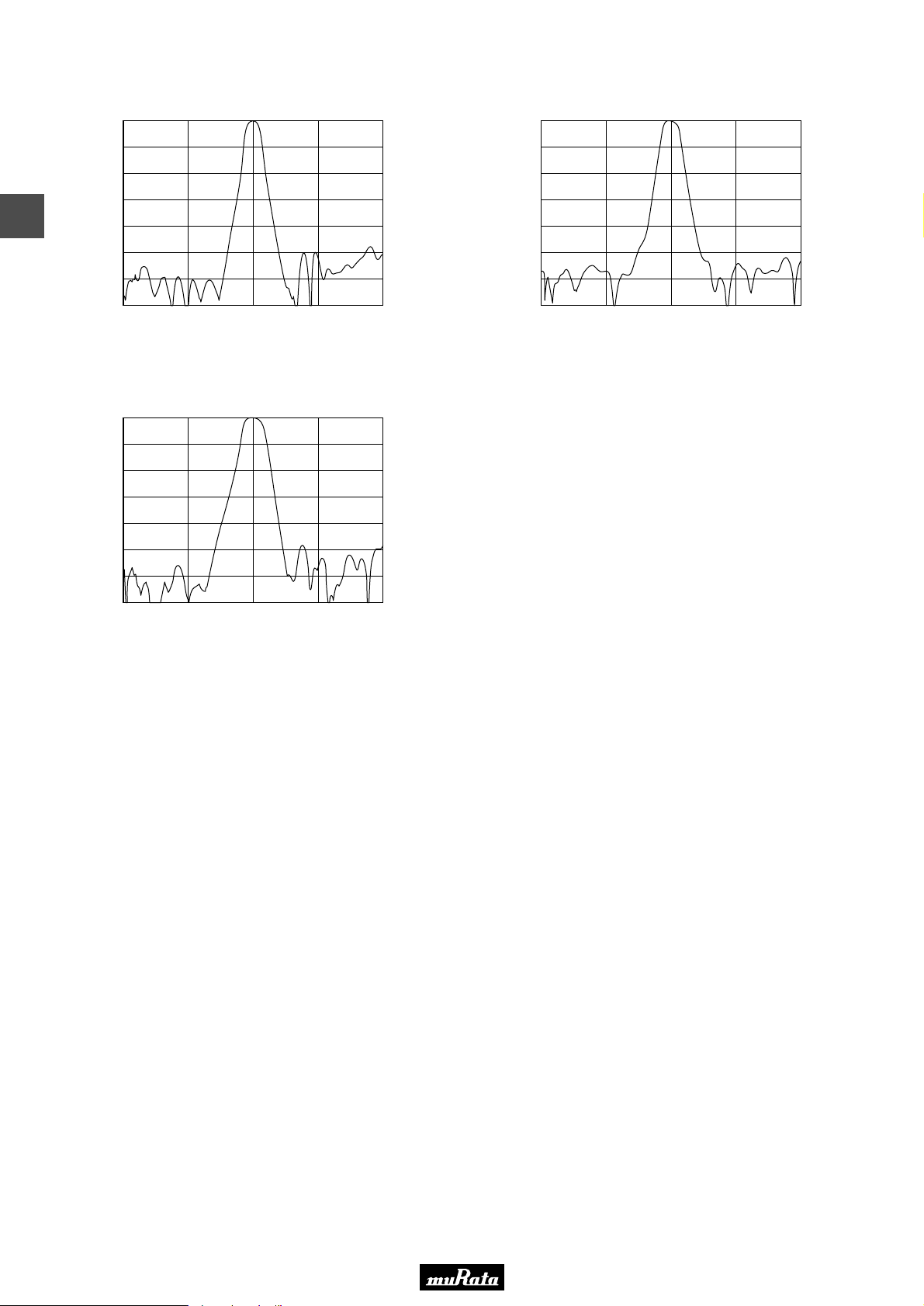
■ Frequency Characteristics (Spurious)
SFELF10M7HA00-B0
0
10
20
30
3
40
Attenuation (dB)
50
60
70
8.700 9.700 10.700 11.700 12.700
Frequency (MHz)
0
10
20
30
40
Attenuation (dB)
50
60
70
8.700 9.700 10.700 11.700 12.700
SFELF10M7FA00-B0
0
10
20
30
40
Attenuation (dB)
50
60
70
8.700 9.700 10.700 11.700 12.700
Frequency (MHz)
SFELF10M7GA00-B0
Frequency (MHz)
P50E.pdf
10.2.9
16
Page 19
• This PDF catalog is downloaded from the website of Murata Manufacturing co., ltd. Therefore, it’s specifications are subject to change or our products in it may be discontinued without advance notice. Please check with our
!Note
• This PDF catalog has only typical specifications because there is no space for detailed specifications. Therefore, please approve our product specifications or transact the approval sheet for product specifications before ordering.
• Please read rating and !CAUTION (for storage, operating, rating, soldering, mounting and handling) in this catalog to prevent smoking and/or burning, etc.
!Note
sales representatives or product engineers before ordering.
• This catalog has only typical specifications because there is no space for detailed specifications. Therefore, please approve our product specifications or transact the approval sheet for product specifications before ordering.
CERAFILr (Filters/Traps/Discriminators) for Audio/Visual Equipment
CERAFILr 10.7MHz Low Loss Type
7.0±2.0
SFELF10M7 series for FM-receivers are monolithic type
ceramic filters which use the thickness expander mode
of the piezoelectric ceramic.
As part of the environment protection activity, solder
for terminal plating and terminal-element connection
inside of ceramic filter contain no lead (Pb).
■ Features
1. Insertion loss is 1 to 1.5dB lower than
conventional products. These types are useful for
elevating the sensitivity of sets.
2. Small dispersion and stable characteristics
3. Excellent shape factor of frequency response
4. Good waveform symmetry
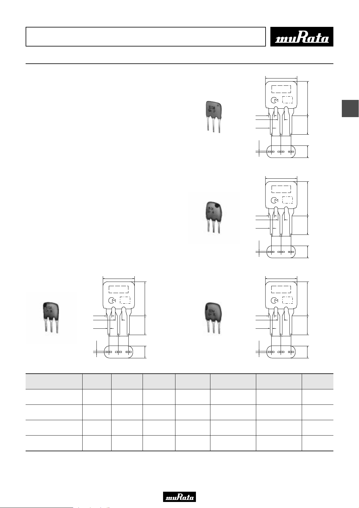
SFELF10M7JAA0-B0
SFELF10M7HAA0-B0
1.38±0.2
1.7±0.1
0.5±0.1
0.3±0.1
1.38±0.2
1.7±0.1
0.5±0.1
0.3±0.1
M A R K I N G
2.5±0.2
(3)
(2)
7.0±2.0
M A R K I N G
2.5±0.2
(3)
(2)
E I A J
C O D E
2.5±0.2
E I A J
C O D E
2.5±0.2
(1)
(1)
7.0±2.0
5.0±1.0
3.0±1.0
7.0±2.0
5.0±1.0
3.0±1.0
(1) : Input
(2) : Ground
(3) : Output
(in mm)
(1) : Input
(2) : Ground
(3) : Output
(in mm)
P50E.pdf
10.2.9
4
SFELF10M7GAA0-B0
Part Number
SFELF10M7JAA0-B0
SFELF10M7HAA0-B0
SFELF10M7GAA0-B0
SFELF10M7FAA0-B0
1.38±0.2
1.7±0.1
0.5±0.1
0.3±0.1
Center
Frequency
(fo) (MHz)
10.700
±30kHz
10.700
±30kHz
10.700
±30kHz
10.700
±30kHz
7.0±2.0
M A R K I N G
E I A J
2.5±0.2
(3)
C O D E
2.5±0.2
(2)
3dB
Bandwidth
(kHz)
7.0±2.0
5.0±1.0
(1) : Input
(2) : Ground
(3) : Output
3.0±1.0
(1)
(in mm)
Attenuation
Insertion Loss
(kHz)
150 ±40kHz 360 max. 4.5 ±2.0dB
180 ±40kHz 470 max. 3.5 ±1.5dB
230 ±50kHz 520 max. 3.0 ±2.0dB
280 ±50kHz 590 max. 2.5 ±2.0dB
SFELF10M7FAA0-B0
(dB)
[within 9MHz to fo]
[within 9MHz to fo]
[within 9MHz to fo]
[within 9MHz to fo]
Spurious
Attenuation
(1) (dB)
35 min.
35 min.
35 min.
30 min.
1.38±0.2
1.7±0.1
0.5±0.1
0.3±0.1
[within fo to 12MHz]
[within fo to 12MHz]
[within fo to 12MHz]
[within fo to 12MHz]
7.0±2.0
M A R K I N G
E I A J
C O D E
2.5±0.2
2.5±0.2
(3)
(2)
Spurious
Attenuation
(2) (dB)
35 min.
35 min.
35 min.
30 min.
(1)
7.0±2.0
5.0±1.0
3.0±1.0
Input/Output
Impedance
Area of Attenuation: [within 20dB]
Area of Insertion Loss: at minimum loss point
Center frequency (fo) defined by the center of 3dB bandwidth.
For safety purposes, connect the output of filters to the IF amplifier through a D.C. blocking capacitor. Avoid applying a direct current to the output of ceramic filters.
The order quantity should be an integral multiple of the "Minimum Quantity" shown in the package page.
(1) : Input
(2) : Ground
(3) : Output
(in mm)
(ohm)
330
330
330
330
17
Page 20
• This PDF catalog is downloaded from the website of Murata Manufacturing co., ltd. Therefore, it’s specifications are subject to change or our products in it may be discontinued without advance notice. Please check with our
!Note
• This PDF catalog has only typical specifications because there is no space for detailed specifications. Therefore, please approve our product specifications or transact the approval sheet for product specifications before ordering.
• Please read rating and !CAUTION (for storage, operating, rating, soldering, mounting and handling) in this catalog to prevent smoking and/or burning, etc.
!Note
sales representatives or product engineers before ordering.
• This catalog has only typical specifications because there is no space for detailed specifications. Therefore, please approve our product specifications or transact the approval sheet for product specifications before ordering.
■ Standard Center Frequency Rank Code
CODE
D
B
A
C
E
Z
M
30kHz Step
10.64MHz±30kHz
10.67MHz±30kHz
10.70MHz±30kHz
10.73MHz±30kHz
10.76MHz±30kHz
25kHz Step
10.650MHz±25kHz
10.675MHz±25kHz
10.700MHz±25kHz
10.725MHz±25kHz
10.750MHz±25kHz
Combination A, B, C, D, E
Combination A, B, C
Color Code
Black
Blue
Red
Orange
White
P50E.pdf
10.2.9
4
■ Test Circuit
Rg
S.S.G
1
R
Rg + R1 = R2 = Input and Output Impedance
C = 10pF (Including stray capacitance and input
capacitance of RF voltmeter.)
(1) (2) (3)
R2
RF
C
Voltmeter
(1) : Input
(2) : Ground
(3) : Output
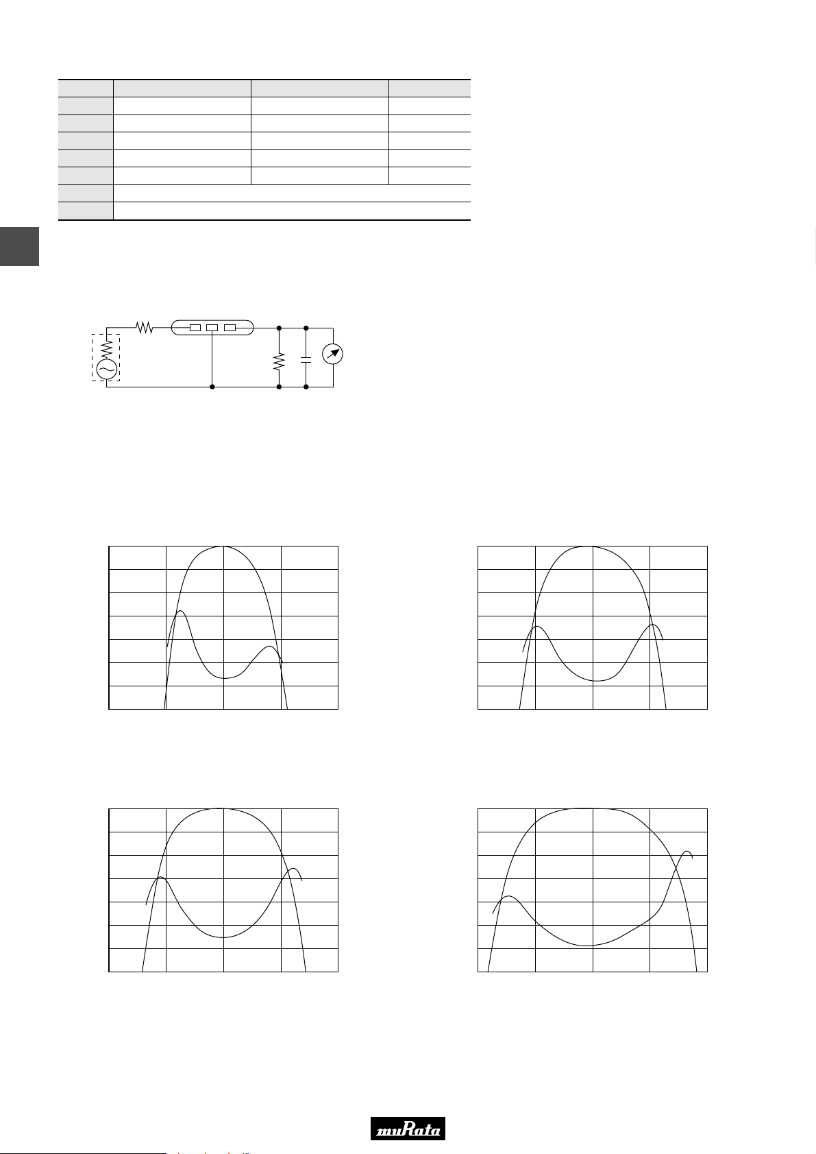
■ Frequency Characteristics
SFELF10M7JAA0-B0
0
1
2
3
4
Attenuation (dB)
5
6
7
10.500 10.600 10.700 10.800 10.900
Frequency (MHz)
7.0
6.5
6.0
5.5
5.0
G.D.T. (µsec.)
4.5
4.0
3.5
0
1
2
3
4
Attenuation (dB)
5
6
7
10.500 10.600 10.700 10.800 10.900
SFELF10M7HAA0-B0
Frequency (MHz)
6.5
6.0
5.5
5.0
4.5
G.D.T. (µsec.)
4.0
3.5
3.0
SFELF10M7GAA0-B0
0
1
2
3
4
Attenuation (dB)
5
6
7
10.500 10.600 10.700 10.800 10.900
Frequency (MHz)
18
SFELF10M7FAA0-B0
6.0
5.5
5.0
4.5
4.0
G.D.T. (µsec.)
3.5
3.0
2.5
0
1
2
3
4
Attenuation (dB)
5
6
7
10.500 10.600 10.700 10.800 10.900
Frequency (MHz)
5.5
5.0
4.5
4.0
3.5
G.D.T. (µsec.)
3.0
2.5
2.0
Page 21
• This PDF catalog is downloaded from the website of Murata Manufacturing co., ltd. Therefore, it’s specifications are subject to change or our products in it may be discontinued without advance notice. Please check with our
!Note
• This PDF catalog has only typical specifications because there is no space for detailed specifications. Therefore, please approve our product specifications or transact the approval sheet for product specifications before ordering.
• Please read rating and !CAUTION (for storage, operating, rating, soldering, mounting and handling) in this catalog to prevent smoking and/or burning, etc.
!Note
sales representatives or product engineers before ordering.
• This catalog has only typical specifications because there is no space for detailed specifications. Therefore, please approve our product specifications or transact the approval sheet for product specifications before ordering.
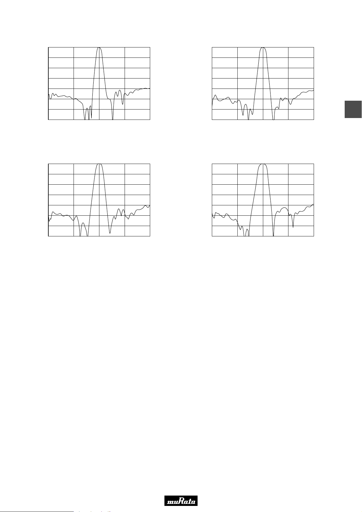
■ Frequency Characteristics (Spurious)
SFELF10M7JAA0-B0
0
10
20
30
40
Attenuation (dB)
50
60
70
8.700 9.700 10.700 11.700 12.700
Frequency (MHz)
0
10
20
30
40
Attenuation (dB)
50
60
70
8.700 9.700 10.700 11.700 12.700
SFELF10M7HAA0-B0
Frequency (MHz)
P50E.pdf
10.2.9
4
SFELF10M7GAA0-B0
0
10
20
30
40
Attenuation (dB)
50
60
70
8.700 9.700 10.700 11.700 12.700
Frequency (MHz)
SFELF10M7FAA0-B0
0
10
20
30
40
Attenuation (dB)
50
60
70
8.700 9.700 10.700 11.700 12.700
Frequency (MHz)
19
Page 22
• This PDF catalog is downloaded from the website of Murata Manufacturing co., ltd. Therefore, it’s specifications are subject to change or our products in it may be discontinued without advance notice. Please check with our
!Note
• This PDF catalog has only typical specifications because there is no space for detailed specifications. Therefore, please approve our product specifications or transact the approval sheet for product specifications before ordering.
• Please read rating and !CAUTION (for storage, operating, rating, soldering, mounting and handling) in this catalog to prevent smoking and/or burning, etc.
!Note
sales representatives or product engineers before ordering.
• This catalog has only typical specifications because there is no space for detailed specifications. Therefore, please approve our product specifications or transact the approval sheet for product specifications before ordering.
CERAFILr (Filters/Traps/Discriminators) for Audio/Visual Equipment
CERAFILr 10.7MHz Low Profile Type
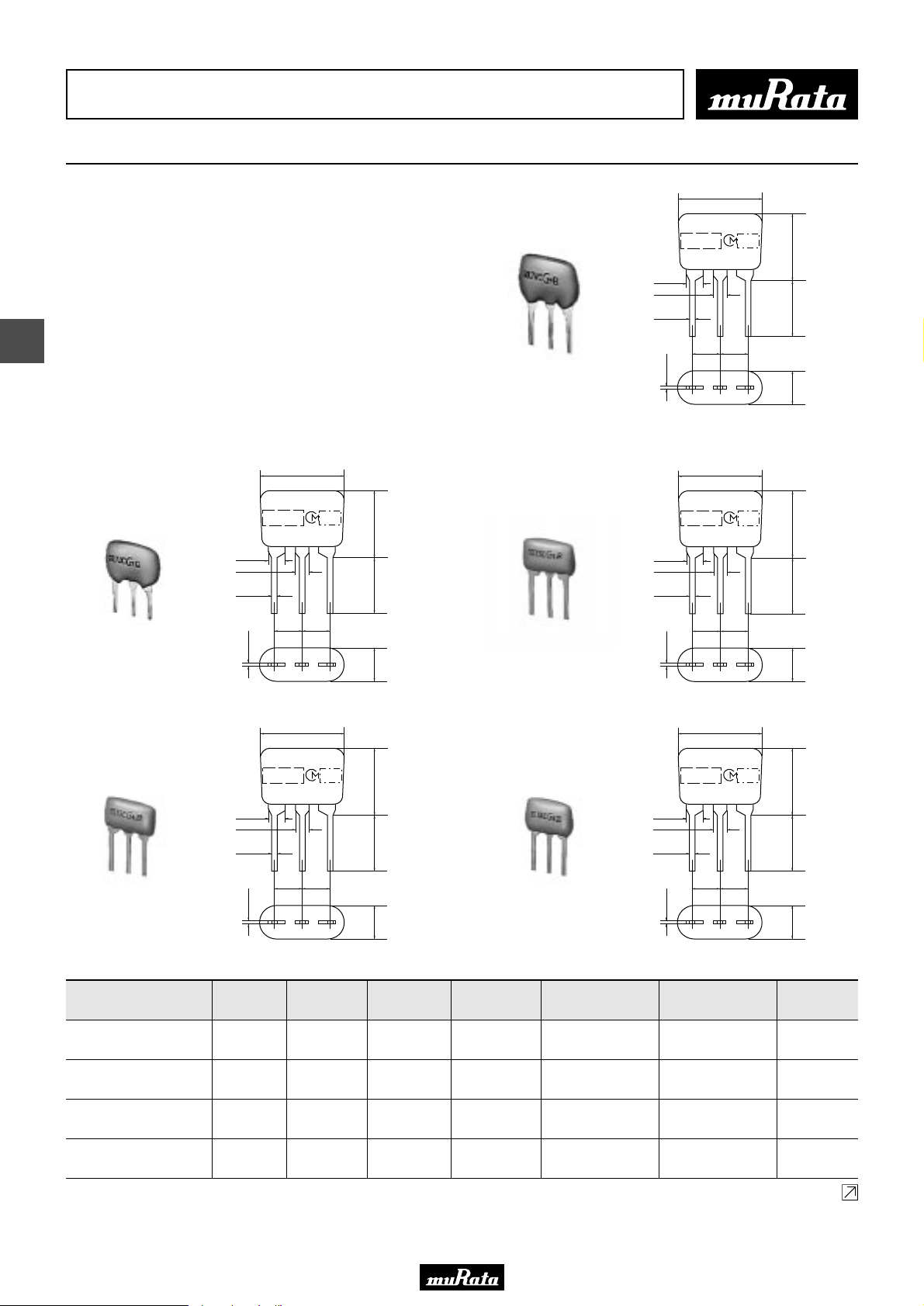
7.5±2.0
SFELG10M7 series for FM-receivers are monolithic type
ceramic filters which use the thickness expander mode
M A R K I N G
of the piezoelectric ceramic.
As part of the environment protection activity, solder
for terminal plating and terminal-element connection
inside of ceramic filter contain no lead (Pb).
1.5±0.1
1.3±0.1
0.5±0.1
5
■ Features
1. Installed height is 6.0mm, making it well suited
for compact, thin sets.
2. Environmental reliability is the same as those of
the ceramic filter SFELF10M7 series.
SFELG10M7KA00-B0
0.3±0.1
(1) (2) (3)
E I A J
C O D E
2.5
±
0.2
2.5±0.2
6.0 max.
5.0±1.0
3.0±1.0
(1) : Input
(2) : Ground
(3) : Output
(in mm)
P50E.pdf
10.2.9
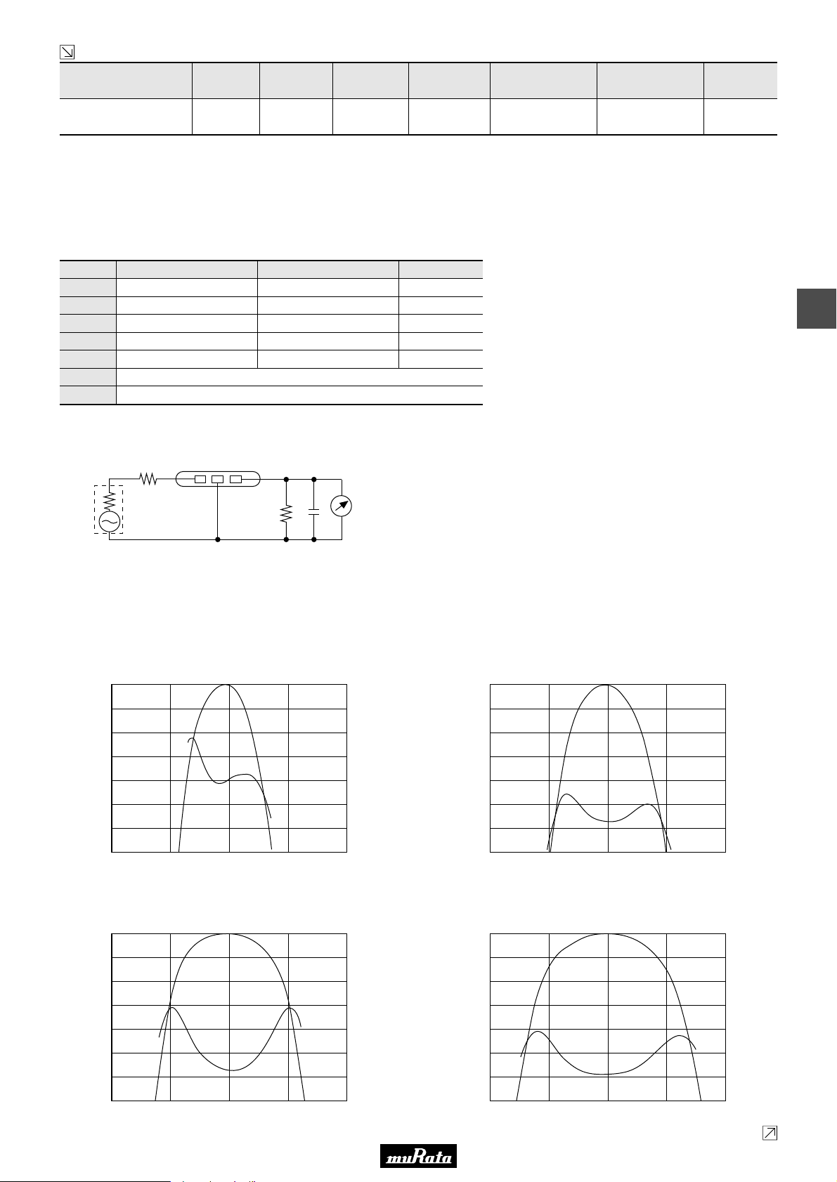
SFELG10M7JA00-B0
SFELG10M7GA00-B0
1.5±0.1
1.3±0.1
0.5±0.1
0.3±0.1
1.5±0.1
1.3±0.1
0.5±0.1
0.3±0.1
7.5±2.0
M A R K I N G
2.5
±
0.2
2.5±0.2
(1) (2) (3)
7.5±2.0
M A R K I N G
2.5
±
0.2
2.5±0.2
(1) (2) (3)
E I A J
C O D E
E I A J
C O D E
6.0 max.
5.0±1.0
3.0±1.0
6.0 max.
5.0±1.0
3.0±1.0
(1) : Input
(2) : Ground
(3) : Output
(in mm)
(1) : Input
(2) : Ground
(3) : Output
(in mm)
SFELG10M7HA00-B0
SFELG10M7FA00-B0
1.5±0.1
1.3±0.1
0.5±0.1
0.3±0.1
1.5±0.1
1.3±0.1
0.5±0.1
0.3±0.1
7.5±2.0
M A R K I N G
2.5
±
0.2
2.5±0.2
(1) (2) (3)
7.5±2.0
M A R K I N G
2.5
±
0.2
2.5±0.2
(1) (2) (3)
E I A J
C O D E
E I A J
C O D E
6.0 max.
5.0±1.0
3.0±1.0
6.0 max.
5.0±1.0
3.0±1.0
(1) : Input
(2) : Ground
(3) : Output
(in mm)
(1) : Input
(2) : Ground
(3) : Output
(in mm)
Part Number
SFELG10M7KA00-B0
SFELG10M7JA00-B0
SFELG10M7HA00-B0
SFELG10M7GA00-B0
20
Center
Frequency
(fo) (MHz)
10.700
±30kHz
10.700
±30kHz
10.700
±30kHz
10.700
±30kHz
3dB
Bandwidth
(kHz)
Attenuation
(kHz)
Insertion Loss
(dB)
110 ±30kHz 350 max. 7.0 ±2.0dB
150 ±40kHz 360 max. 4.5 ±2.0dB
180 ±40kHz 470 max. 3.5 ±2.0dB
230 ±50kHz 570 max. 3.0 ±2.0dB
Spurious
Attenuation
(1) (dB)
30 min.
[within 9MHz to fo]
35 min.
[within 9MHz to fo]
35 min.
[within 9MHz to fo]
40 min.
[within 9MHz to fo]
Spurious
Attenuation
(2) (dB)
30 min.
[within fo to 12MHz]
35 min.
[within fo to 12MHz]
35 min.
[within fo to 12MHz]
40 min.
[within fo to 12MHz]
Continued on the following page.
Input/Output
Impedance
(ohm)
330
330
330
330
Page 23
• This PDF catalog is downloaded from the website of Murata Manufacturing co., ltd. Therefore, it’s specifications are subject to change or our products in it may be discontinued without advance notice. Please check with our
!Note
• This PDF catalog has only typical specifications because there is no space for detailed specifications. Therefore, please approve our product specifications or transact the approval sheet for product specifications before ordering.
• Please read rating and !CAUTION (for storage, operating, rating, soldering, mounting and handling) in this catalog to prevent smoking and/or burning, etc.
!Note
sales representatives or product engineers before ordering.
• This catalog has only typical specifications because there is no space for detailed specifications. Therefore, please approve our product specifications or transact the approval sheet for product specifications before ordering.
Continued from the preceding page.
Part Number
SFELG10M7FA00-B0
Center
Frequency
(fo) (MHz)
10.700
±30kHz
3dB
Bandwidth
(kHz)
Attenuation
(kHz)
Insertion Loss
(dB)
280 ±50kHz 650 max. 3.0 ±2.0dB
Spurious
Attenuation
(1) (dB)
30 min.
[within 9MHz to fo]
Spurious
Attenuation
(2) (dB)
30 min.
[within fo to 12MHz]
Area of Attenuation: [within 20dB]
Area of Insertion Loss: at minimum loss point
Center frequency (fo) defined by the center of 3dB bandwidth.
For safety purposes, connect the output of filters to the IF amplifier through a D.C. blocking capacitor. Avoid applying a direct current to the output of ceramic filters.
The order quantity should be an integral multiple of the "Minimum Quantity" shown in the package page.
■ Standard Center Frequency Rank Code
CODE
D
B
A
C
E
Z
M
30kHz Step
10.64MHz±30kHz
10.67MHz±30kHz
10.70MHz±30kHz
10.73MHz±30kHz
10.76MHz±30kHz
25kHz Step
10.650MHz±25kHz
10.675MHz±25kHz
10.700MHz±25kHz
10.725MHz±25kHz
10.750MHz±25kHz
Combination A, B, C, D, E
Combination A, B, C
Color Code
Black
Blue
Red
Orange
White
Input/Output
Impedance
(ohm)
330
P50E.pdf
10.2.9
5
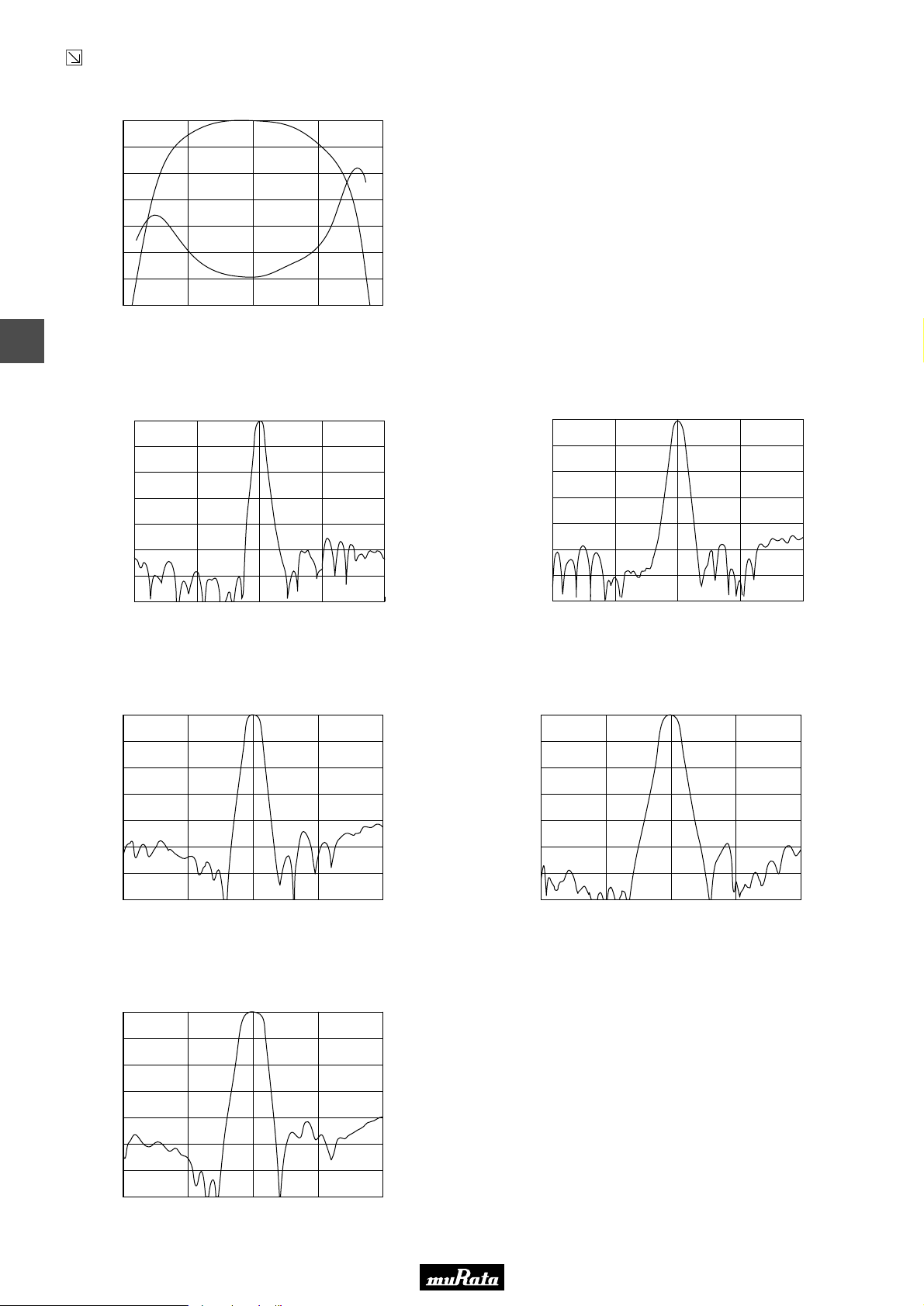
■ Test Circuit
(1) (2) (3)
S.S.G
1
R
Rg
Rg + R1 = R2 = Input and Output Impedance
C = 10pF (Including stray capacitance and input
capacitance of RF voltmeter.)
■ Frequency Characteristics
SFELG10M7KA00-B0
0
1
2
3
4
Attenuation (dB)
5
6
7
10.70010.60010.500 10.800 10.900
Frequency (MHz)
RF
C
R2
Voltmeter
(1) : Input
(2) : Ground
(3) : Output
SFELG10M7JA00-B0
8.0
7.5
7.0
6.5
6.0
G.D.T. (µsec.)
5.5
5.0
4.5
0
1
2
3
4
Attenuation (dB)
5
6
7
10.70010.60010.500 10.800 10.900
Frequency (MHz)
7.5
7.0
6.5
6.0
5.5
G.D.T. (µsec.)
5.0
4.5
4.0
SFELG10M7HA00-B0
0
1
2
3
4
Attenuation (dB)
5
6
7
10.500 10.600 10.700 10.800 10.900
Frequency (MHz)
SFELG10M7GA00-B0
6.5
6.0
5.5
5.0
4.5
G.D.T. (µsec.)
4.0
3.5
3.0
0
1
2
3
4
Attenuation (dB)
5
6
7
10.500 10.600 10.700 10.800 10.900
Frequency (MHz)
Continued on the following page.
6.0
5.5
5.0
4.5
4.0
G.D.T. (µsec.)
3.5
3.0
2.5
21
Page 24
• This PDF catalog is downloaded from the website of Murata Manufacturing co., ltd. Therefore, it’s specifications are subject to change or our products in it may be discontinued without advance notice. Please check with our
!Note
• This PDF catalog has only typical specifications because there is no space for detailed specifications. Therefore, please approve our product specifications or transact the approval sheet for product specifications before ordering.
• Please read rating and !CAUTION (for storage, operating, rating, soldering, mounting and handling) in this catalog to prevent smoking and/or burning, etc.
!Note
sales representatives or product engineers before ordering.
• This catalog has only typical specifications because there is no space for detailed specifications. Therefore, please approve our product specifications or transact the approval sheet for product specifications before ordering.
Continued from the preceding page.
■ Frequency Characteristics
SFELG10M7FA00-B0
0
1
2
3
4
Attenuation (dB)
5
6
7
10.500 10.600 10.700 10.800 10.900
Frequency (MHz)
5.5
5.0
4.5
4.0
3.5
3.,0
2.5
2.0
G.D.T. (µsec.)
5
■ Frequency Characteristics (Spurious)
SFELG10M7KA00-B0
0
10
20
30
40
Attenuation (dB)
50
60
70
8.700 9.700 10.700 11.700 12.700
Frequency (MHz)
0
10
20
30
40
Attenuation (dB)
50
60
70
SFELG10M7JA00-B0
9.7008.700 11.700 12.700
10.700
Frequency (MHz)
P50E.pdf
10.2.9
SFELG10M7HA00-B0
0
10
20
30
40
Attenuation (dB)
50
60
70
8.700 9.700 10.700 11.700 12.700
Frequency (MHz)
SFELG10M7FA00-B0
0
10
20
30
40
Attenuation (dB)
50
60
70
8.700 9.700 10.700 11.700 12.700
Frequency (MHz)
SFELG10M7GA00-B0
0
10
20
30
40
Attenuation (dB)
50
60
70
8.700 9.700 10.700 11.700 12.700
Frequency (MHz)
22
Page 25
• This PDF catalog is downloaded from the website of Murata Manufacturing co., ltd. Therefore, it’s specifications are subject to change or our products in it may be discontinued without advance notice. Please check with our
!Note
• This PDF catalog has only typical specifications because there is no space for detailed specifications. Therefore, please approve our product specifications or transact the approval sheet for product specifications before ordering.
• Please read rating and !CAUTION (for storage, operating, rating, soldering, mounting and handling) in this catalog to prevent smoking and/or burning, etc.
!Note
sales representatives or product engineers before ordering.
• This catalog has only typical specifications because there is no space for detailed specifications. Therefore, please approve our product specifications or transact the approval sheet for product specifications before ordering.
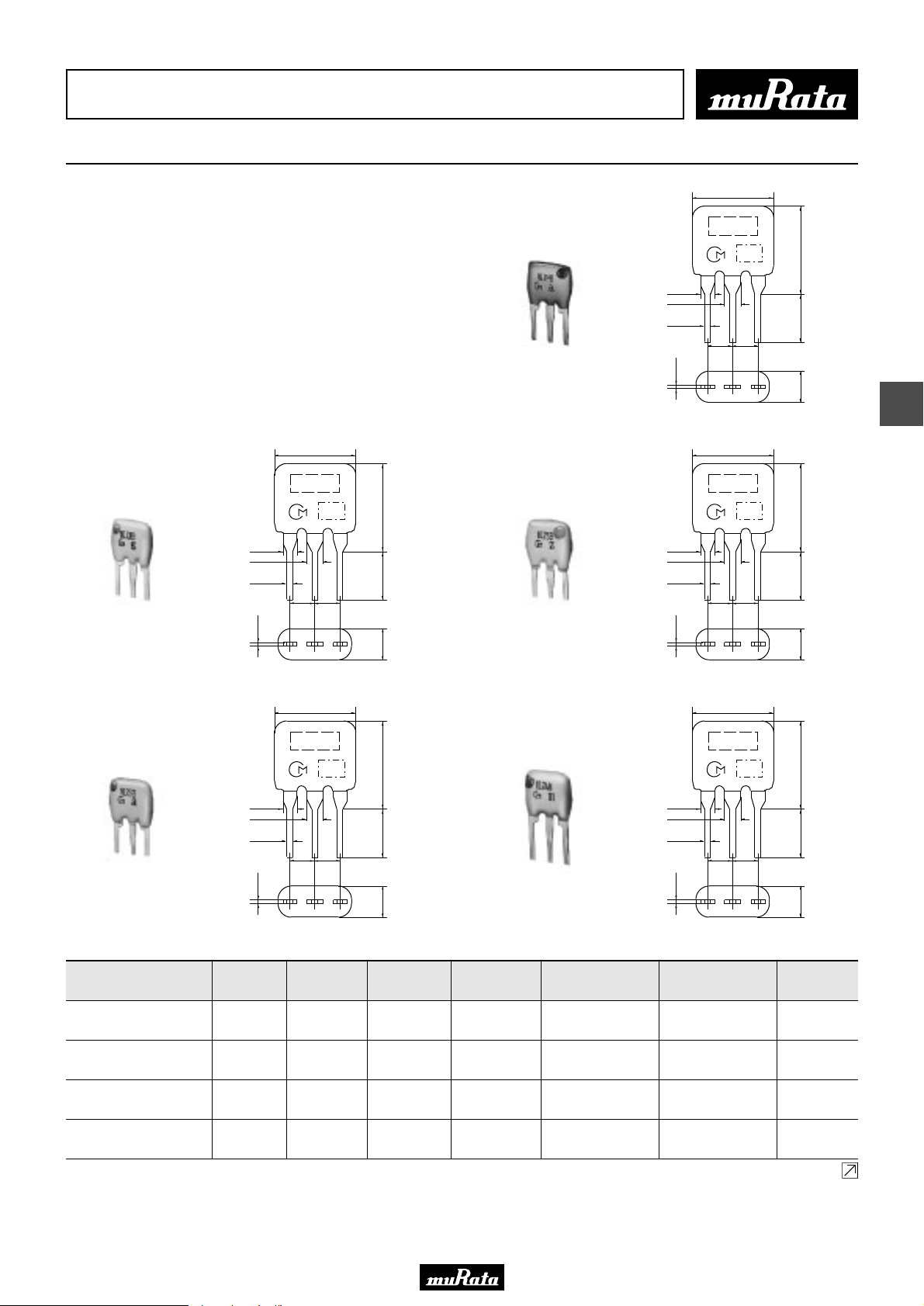
CERAFILr (Filters/Traps/Discriminators) for Audio/Visual Equipment
CERAFILr 10.7MHz Low Spurious Response Type
7.5±2.0
P50E.pdf
10.2.9
SFELF10M7 series for FM-receivers are monolithic type
ceramic filters which use the thickness expander mode
of the piezoelectric ceramic.
As part of the environment protection activity, solder
for terminal plating and terminal-element connection
inside of ceramic filter contain no lead (Pb).
■ Features
These types have lower spurious response compared
to the standard filters.
7.5±2.0
MARKING
EIAJ
SFELF10M7JAB0-B0
1.38±0.2
1.7±0.1
0.5±0.1
0.3±0.1
2.5±0.2
(3)
CODE
2.5±0.2
(2)
7.0±2.0
5.0±1.03.0±1.0
(1)
(in mm)
SFELF10M7KAB0-B0
SFELF10M7HAB0-B0
1.38±0.2
1.7±0.1
0.5±0.1
0.3±0.1
1.38±0.2
1.7±0.1
0.5±0.1
0.3±0.1
2.5±0.2
(3)
2.5±0.2
(3)
MARKING
EIAJ
CODE
2.5±0.2
(2)
7.5±2.0
MARKING
EIAJ
CODE
2.5±0.2
(2)
7.0±2.0
5.0±1.03.0±1.0
(1)
(1)
(in mm)
7.0±2.0
5.0±1.03.0±1.0
(in mm)
6
SFELF10M7GAB0-B0
Part Number
SFELF10M7KAB0-B0
SFELF10M7JAB0-B0
SFELF10M7HAB0-B0
SFELF10M7GAB0-B0
1.38±0.2
1.7±0.1
0.5±0.1
0.3±0.1
Center
Frequency
(fo) (MHz)
10.700
±30kHz
10.700
±30kHz
10.700
±30kHz
10.700
±30kHz
7.5±2.0
MARKING
EIAJ
2.5±0.2
2.5±0.2
(3)
(2)
3dB
Bandwidth
(kHz)
CODE
(1)
7.0±2.0
5.0±1.03.0±1.0
(in mm)
Attenuation
(kHz)
Insertion Loss
(dB)
110 ±30kHz 350 max. 7.0 ±2.0dB
150 ±40kHz 380 max. 5.5 ±2.0dB
180 ±40kHz 520 max. 5.0 ±2.0dB
230 ±50kHz 570 max. 3.0 ±2.0dB
SFELF10M7FAB0-B0
Spurious
Attenuation
(1) (dB)
45 min.
[within 9MHz to fo]
45 min.
[within 9MHz to fo]
45 min.
[within 9MHz to fo]
45 min.
[within 9MHz to fo]
7.5±2.0
MARKING
EIAJ
CODE
1.38±0.2
1.7±0.1
0.5±0.1
2.5±0.2
2.5±0.2
0.3±0.1
(3)
Spurious
Attenuation
(2) (dB)
(1)
(2)
30 min.
[within fo to 12MHz]
45 min.
[within fo to 12MHz]
45 min.
[within fo to 12MHz]
45 min.
[within fo to 12MHz]
Continued on the following page.
7.0±2.0
5.0±1.03.0±1.0
(in mm)
Input/Output
Impedance
(ohm)
330
330
330
330
23
Page 26
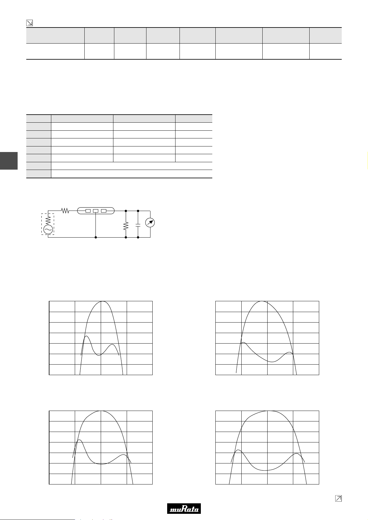
• This PDF catalog is downloaded from the website of Murata Manufacturing co., ltd. Therefore, it’s specifications are subject to change or our products in it may be discontinued without advance notice. Please check with our
!Note
• This PDF catalog has only typical specifications because there is no space for detailed specifications. Therefore, please approve our product specifications or transact the approval sheet for product specifications before ordering.
• Please read rating and !CAUTION (for storage, operating, rating, soldering, mounting and handling) in this catalog to prevent smoking and/or burning, etc.
!Note
sales representatives or product engineers before ordering.
• This catalog has only typical specifications because there is no space for detailed specifications. Therefore, please approve our product specifications or transact the approval sheet for product specifications before ordering.
Continued from the preceding page.
Part Number
SFELF10M7FAB0-B0
Center
Frequency
(fo) (MHz)
10.700
±30kHz
3dB
Bandwidth
(kHz)
Attenuation
(kHz)
Insertion Loss
(dB)
280 ±50kHz 650 max. 3.0 ±2.0dB
Spurious
Attenuation
(1) (dB)
45 min.
[within 9MHz to fo]
Spurious
Attenuation
(2) (dB)
45 min.
[within fo to 12MHz]
Area of Attenuation: [within 20dB]
Area of Insertion Loss: at minimum loss point
Center frequency (fo) defined by the center of 3dB bandwidth.
For safety purposes, connect the output of filters to the IF amplifier through a D.C. blocking capacitor. Avoid applying a direct current to the output of ceramic filters.
The order quantity should be an integral multiple of the "Minimum Quantity" shown in the package page.
■ Standard Center Frequency Rank Code
CODE
D
B
A
C
6
E
Z
M
30kHz Step
10.64MHz±30kHz
10.67MHz±30kHz
10.70MHz±30kHz
10.73MHz±30kHz
10.76MHz±30kHz
Combination A, B, C, D, E
Combination A, B, C
25kHz Step
10.650MHz±25kHz
10.675MHz±25kHz
10.700MHz±25kHz
10.725MHz±25kHz
10.750MHz±25kHz
Color Code
Black
Blue
Red
Orange
White
Input/Output
Impedance
(ohm)
330
P50E.pdf
10.2.9
■ Test Circuit
(1) (2) (3)
S.S.G
1
R
Rg
Rg + R1 = R2 = Input and Output Impedance
C = 10pF (Including stray capacitance and input
capacitance of RF voltmeter.)
■ Frequency Characteristics
SFELF10M7KAB0-B0
0
1
2
3
4
Attenuation (dB)
5
6
7
10.70010.60010.500 10.800 10.900
Frequency (MHz)
RF
C
R2
Voltmeter
(1) : Input
(2) : Ground
(3) : Output
SFELF10M7JAB0-B0
8.0
7.5
7.0
6.5
6.0
G.D.T. (µsec.)
5.5
5.0
4.5
0
1
2
3
4
Attenuation (dB)
5
6
7
10.70010.60010.500 10.800 10.900
Frequency (MHz)
7.0
6.5
6.0
5.5
5.0
G.D.T. (µsec.)
4.5
4.0
3.5
SFELF10M7HAB0-B0
0
1
2
3
4
Attenuation (dB)
5
6
7
10.500 10.600 10.700 10.800 10.900
Frequency (MHz)
24
SFELF10M7GAB0-B0
6.5
6.0
5.5
5.0
4.5
G.D.T. (µsec.)
4.0
3.5
3.0
0
1
2
3
4
Attenuation (dB)
5
6
7
10.500 10.600 10.700 10.800 10.900
Frequency (MHz)
Continued on the following page.
6.0
5.5
5.0
4.5
4.0
G.D.T. (µsec.)
3.5
3.0
2.5
Page 27
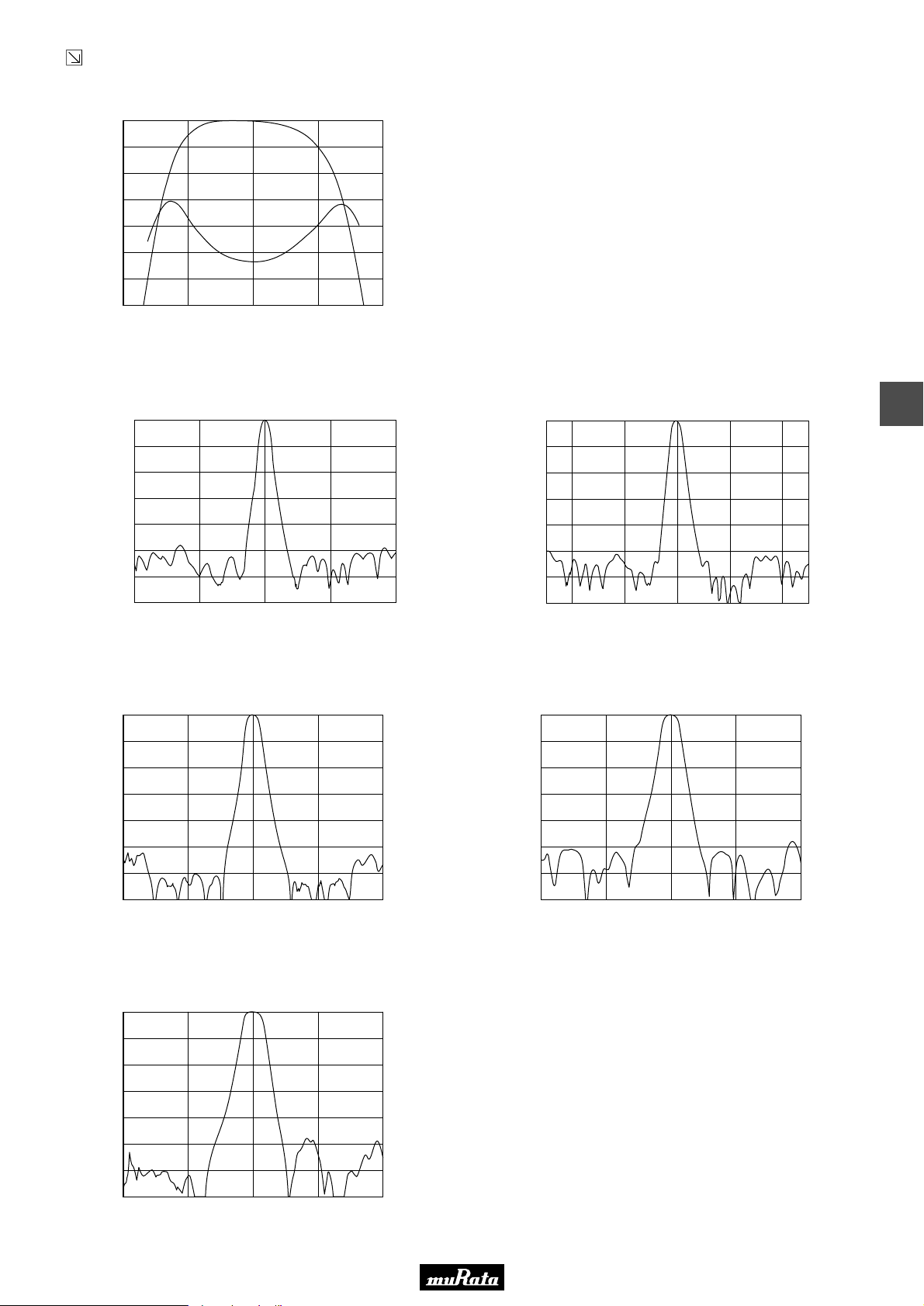
• This PDF catalog is downloaded from the website of Murata Manufacturing co., ltd. Therefore, it’s specifications are subject to change or our products in it may be discontinued without advance notice. Please check with our
!Note
• This PDF catalog has only typical specifications because there is no space for detailed specifications. Therefore, please approve our product specifications or transact the approval sheet for product specifications before ordering.
• Please read rating and !CAUTION (for storage, operating, rating, soldering, mounting and handling) in this catalog to prevent smoking and/or burning, etc.
!Note
sales representatives or product engineers before ordering.
• This catalog has only typical specifications because there is no space for detailed specifications. Therefore, please approve our product specifications or transact the approval sheet for product specifications before ordering.
Continued from the preceding page.
■ Frequency Characteristics
SFELF10M7FAB0-B0
0
1
2
3
4
Attenuation (dB)
5
6
7
10.500 10.600 10.700 10.800 10.900
Frequency (MHz)
5.5
5.0
4.5
4.0
3.5
G.D.T. (µsec.)
3.0
2.5
2.0
■ Frequency Characteristics (Spurious)
SFELF10M7KAB0-B0
0
10
20
30
40
Attenuation (dB)
50
60
70
10.700 11.700 12.7008.700 9.700
Frequency (MHz)
0
10
20
30
40
Attenuation (dB)
50
60
70
SFELF10M7JAB0-B0
10.700 11.700 12.7008.700 9.700
Frequency (MHz)
P50E.pdf
10.2.9
6
SFELF10M7HAB0-B0
0
10
20
30
40
Attenuation (dB)
50
60
70
8.700 9.700 10.700 11.700 12.700
Frequency (MHz)
SFELF10M7FAB0-B0
0
10
20
30
40
Attenuation (dB)
50
60
70
8.700 9.700 10.700 11.700 12.700
Frequency (MHz)
SFELF10M7GAB0-B0
0
10
20
30
40
Attenuation (dB)
50
60
70
8.700 9.700 10.700 11.700 12.700
Frequency (MHz)
25
Page 28
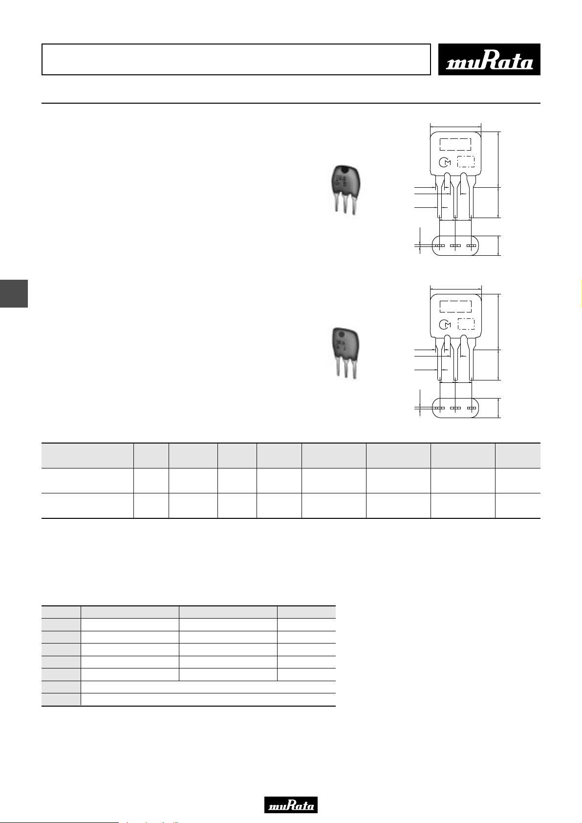
• This PDF catalog is downloaded from the website of Murata Manufacturing co., ltd. Therefore, it’s specifications are subject to change or our products in it may be discontinued without advance notice. Please check with our
!Note
• This PDF catalog has only typical specifications because there is no space for detailed specifications. Therefore, please approve our product specifications or transact the approval sheet for product specifications before ordering.
• Please read rating and !CAUTION (for storage, operating, rating, soldering, mounting and handling) in this catalog to prevent smoking and/or burning, etc.
!Note
sales representatives or product engineers before ordering.
• This catalog has only typical specifications because there is no space for detailed specifications. Therefore, please approve our product specifications or transact the approval sheet for product specifications before ordering.
CERAFILr (Filters/Traps/Discriminators) for Audio/Visual Equipment
CERAFILr 10.7MHz Wide Bandwidth Type
7.0±2.0
SFELF10M7 series for FM-receivers are monolithic type
ceramic filters which use the thickness expander mode
of the piezoelectric ceramic.
As part of the environment protection activity, solder
for terminal plating and terminal-element connection
inside of ceramic filter contain no lead (Pb).
■ Features
Realizes wider band characteristics not obtained by
conventional ceramic filters.
SFELF10M7EA00-B0
7
SFELF10M7DF00-B0
1.38±0.2
1.7±0.1
0.5±0.1
0.3±0.1
1.38±0.2
1.7±0.1
0.5±0.1
0.3±0.1
M A R K I N G
2.5±0.2
(3)
7.0±2.0
M A R K I N G
2.5±0.2
(3)
(2)
(2)
E I A J
C O D E
2.5±0.2
E I A J
C O D E
2.5±0.2
(1)
(1)
7.0±2.0
5.0±1.0
3.0±1.0
7.0±2.0
5.0±1.0
3.0±1.0
(1) : Input
(2) : Ground
(3) : Output
(in mm)
(1) : Input
(2) : Ground
(3) : Output
(in mm)
P50E.pdf
10.2.9
Center
Part Number
SFELF10M7EA00-B0
Frequency
(fo) (MHz)
±30kHz
SFELF10M7DF00-B0
Area of Attenuation: [within 20dB]
Area of Insertion Loss: at minimum loss point
Center frequency (fo) defined by the center of 3dB bandwidth.
For safety purposes, connect the output of filters to the IF amplifier through a D.C. blocking capacitor. Avoid applying a direct current to the output of ceramic filters.
The order quantity should be an integral multiple of the "Minimum Quantity" shown in the package page.
Nominal Center
Frequency (fn)
(MHz)
10.700
- 330 ±50kHz 680 max. 4.0 ±2.0dB
- 10.700 fn±175 min. 950 max. 3.0 ±2.0dB
3dB
Bandwidth
(kHz)
Attenuation
(kHz)
Insertion Loss
(dB)
Spurious
Attenuation
(1) (dB)
30 min.
[within 9MHz to fo]
20 min.
[within 5MHz to fn]
Spurious
Attenuation
(2) (dB)
30 min.
[within fo to 12MHz]
20 min.
[within fn to 15MHz]
■ Standard Center Frequency Rank Code (SFELF10M7EA00-B0)
CODE
D
B
A
C
E
Z
M
30kHz Step
10.64MHz±30kHz
10.67MHz±30kHz
10.70MHz±30kHz
10.73MHz±30kHz
10.76MHz±30kHz
25kHz Step
10.650MHz±25kHz
10.675MHz±25kHz
10.700MHz±25kHz
10.725MHz±25kHz
10.750MHz±25kHz
Combination A, B, C, D, E
Combination A, B, C
Color Code
Black
Blue
Red
Orange
White
Input/Output
Impedance
(ohm)
330
470
26
Page 29
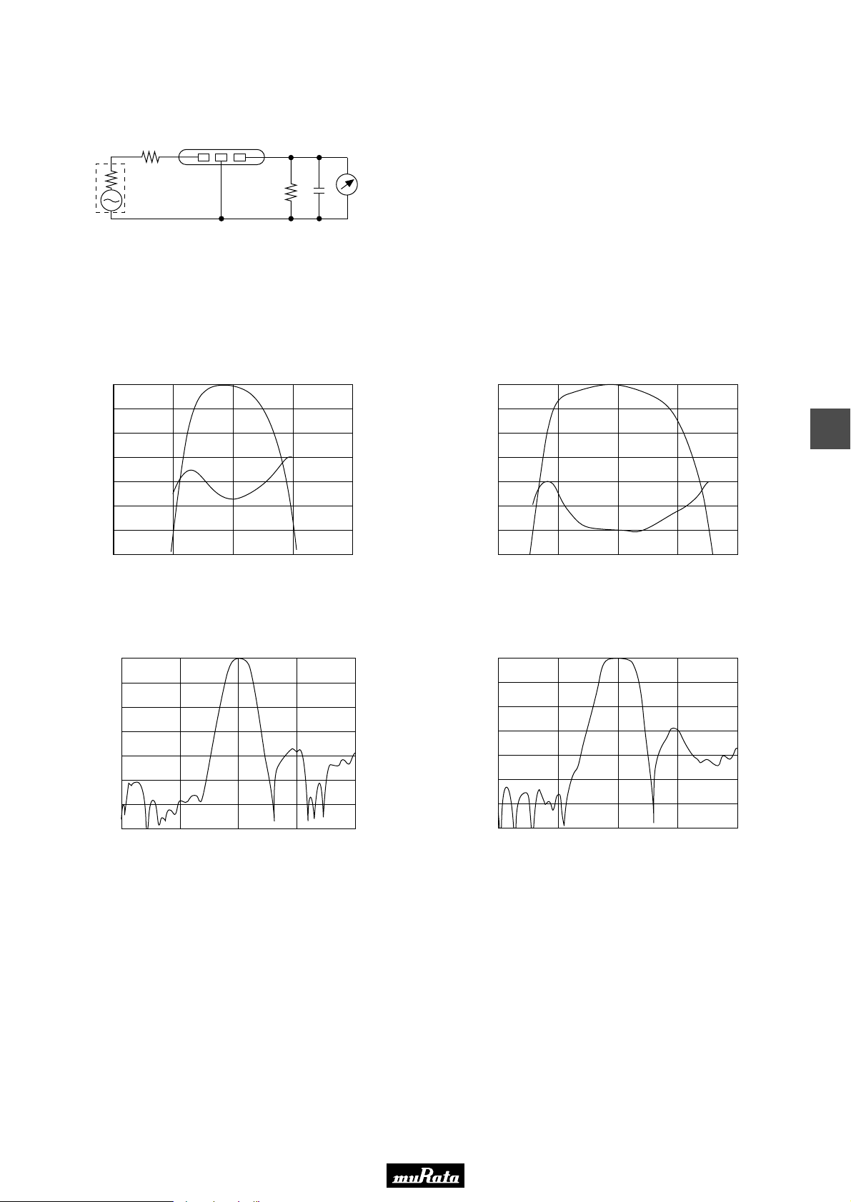
• This PDF catalog is downloaded from the website of Murata Manufacturing co., ltd. Therefore, it’s specifications are subject to change or our products in it may be discontinued without advance notice. Please check with our
!Note
• This PDF catalog has only typical specifications because there is no space for detailed specifications. Therefore, please approve our product specifications or transact the approval sheet for product specifications before ordering.
• Please read rating and !CAUTION (for storage, operating, rating, soldering, mounting and handling) in this catalog to prevent smoking and/or burning, etc.
!Note
sales representatives or product engineers before ordering.
• This catalog has only typical specifications because there is no space for detailed specifications. Therefore, please approve our product specifications or transact the approval sheet for product specifications before ordering.
■ Test Circuit
P50E.pdf
10.2.9
(1) (2) (3)
S.S.G
1
R
Rg
Rg + R1 = R2 = Input and Output Impedance
C = 10pF (Including stray capacitance and input
capacitance of RF voltmeter.)
■ Frequency Characteristics
SFELF10M7EA00-B0
0
1
2
3
4
Attenuation (dB)
5
6
7
10.70010.50010.300 10.900 11.100
Frequency (MHz)
RF
C
R2
Voltmeter
(1) : Input
(2) : Ground
(3) : Output
SFELF10M7DF00-B0
4.5
4.0
3.5
3.0
2.5
G.D.T. (µsec.)
2.0
1.5
1.0
0
1
2
3
4
Attenuation (dB)
5
6
7
10.300 10.500 10.700 10.900 11.100
Frequency (MHz)
4.5
4.0
3.5
3.0
2.5
G.D.T. (µsec.)
2.0
1.5
1.0
7
■ Frequency Characteristics (Spurious)
SFELF10M7EA00-B0
0
10
20
30
40
Attenuation (dB)
50
60
70
8.700 9.700 10.700 11.700 12.700
Frequency (MHz)
SFELF10M7DF00-B0
0
10
20
30
40
Attenuation (dB)
50
60
70
8.700 9.700 10.700 11.700 12.700
Frequency (MHz)
27
Page 30
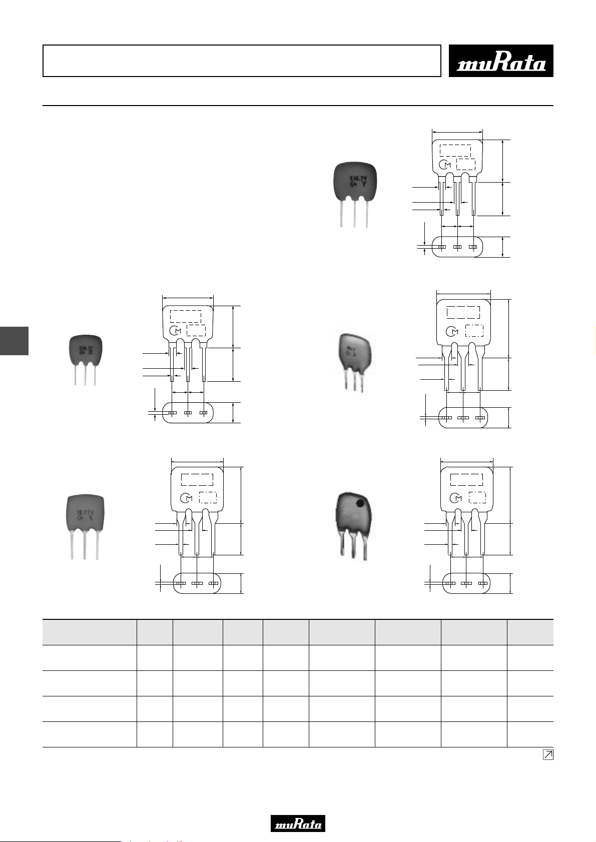
• This PDF catalog is downloaded from the website of Murata Manufacturing co., ltd. Therefore, it’s specifications are subject to change or our products in it may be discontinued without advance notice. Please check with our
!Note
• This PDF catalog has only typical specifications because there is no space for detailed specifications. Therefore, please approve our product specifications or transact the approval sheet for product specifications before ordering.
• Please read rating and !CAUTION (for storage, operating, rating, soldering, mounting and handling) in this catalog to prevent smoking and/or burning, etc.
!Note
sales representatives or product engineers before ordering.
• This catalog has only typical specifications because there is no space for detailed specifications. Therefore, please approve our product specifications or transact the approval sheet for product specifications before ordering.
CERAFILr (Filters/Traps/Discriminators) for Audio/Visual Equipment
CERAFILr 10.7MHz Narrow Bandwidth Type
7.0±2.0
■ Features
SFELF10M7LFTA/KAH0, SFVLF/SFKLF series realizes
narrower band characteristics not obtained by
conventional ceramic filters. Besides, low spurious
and temperature characteristics is stable. This series
is suitable for European car-audio or AM up conversion
use that needs narrow band characteristics are stable.
As part of the environment protection activity, solder
for terminal plating and terminal-element connection
inside of ceramic filter contain no lead (Pb).
SFVLF10M7MF00-B0
1.65±0.1
1.4±0.1
0.5±0.1
0.3±0.1
MARKING
EIAJ
CODE
2.5±0.2
2.5±0.2
(3) (2) (1)
7.0±2.05.0±1.03.0±1.0
(1) : Input
(2) : Ground
(3) : Output
(in mm)
P50E.pdf
10.2.9
1.38±0.2
1.7±0.1
0.5±0.1
0.3±0.1
10.0±2.0
M A R K I N G
2.5±0.2
(3)
M A R K I N G
2.5±0.2
(3)
E I A J
C O D E
2.5±0.2
(2)
7.0±2.0
2.5±0.2
(2)
E I A J
C O D E
10.0±2.0
5.0±1.0
(1) : Input
(2) : Ground
–1.0
+1.5
(3) : Output
3.5
7.0±2.0
5.0±1.0
3.0±1.0
(in mm)
(1) : Input
(2) : Ground
(3) : Output
(in mm)
(1)
(1)
7.0±2.0
MARKING
EIAJ
CODE
8
SFVLF10M7LF00-B0
SFELF10M7LFTA-B0
1.65±0.1
1.4±0.1
0.5±0.1
0.3±0.1
1.38±0.2
1.7±0.1
2.5±0.2
(3) (2) (1)
0.5±0.1
0.3±0.1
(3)
2.5±0.2
7.0±2.0
M A R K I N G
E I A J
C O D E
2.5±0.2
2.5±0.2
(2)
7.0±2.05.0±1.03.0±1.0
1.38±0.2
1.7±0.1
0.5±0.1
(1) : Input
(2) : Ground
(3) : Output
(in mm)
7.0±2.0
5.0±1.0
(1) : Input
(2) : Ground
(3) : Output
3.0±1.0
(1)
(in mm)
SFKLF10M7NL00-B0
SFELF10M7KAH0-B0
0.3±0.1
Part Number
SFVLF10M7MF00-B0
SFVLF10M7LF00-B0
SFKLF10M7NL00-B0
SFELF10M7LFTA-B0
28
Center
Frequency
(fo) (MHz)
Nominal Center
Frequency (fn)
(MHz)
3dB
Bandwidth
(kHz)
Attenuation
(kHz)
- 10.700 fn±13 min. 135 max. 5.0 ±2.0dB
- 10.700 fn±25 min. - 5.5 ±2.5dB
10.700
±15kHz
- 20 min. 95 max. 6.0 max.
- 10.700 fn±25 min. 280 max. 7.0 ±2.0dB
Insertion Loss
(dB)
Spurious
Attenuation
(1) (dB)
35 min.
[within 9MHz to fn]
30 min.
[within 9MHz to fn]
24 min.
[within fo-1MHz to fo]
30 min.
[within 9MHz to fn]
Spurious
Attenuation
(2) (dB)
35 min.
[within fn to 12MHz]
30 min.
[within fn to 12MHz]
24 min.
[within fo to fo+1MHz]
30 min.
[within fn to 12MHz]
Input/Output
Impedance
(ohm)
330
330
600
330
Continued on the following page.
Page 31
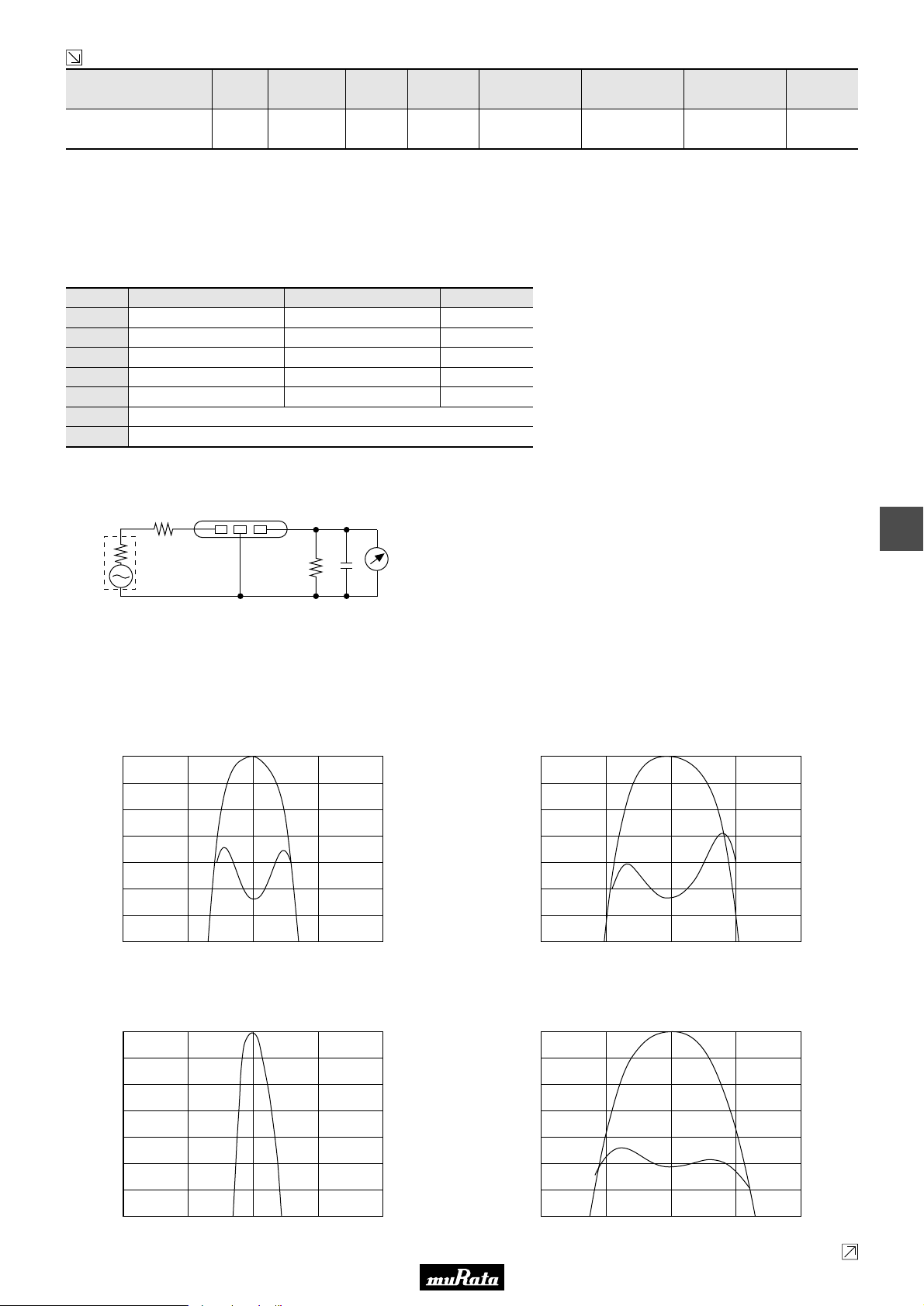
• This PDF catalog is downloaded from the website of Murata Manufacturing co., ltd. Therefore, it’s specifications are subject to change or our products in it may be discontinued without advance notice. Please check with our
!Note
• This PDF catalog has only typical specifications because there is no space for detailed specifications. Therefore, please approve our product specifications or transact the approval sheet for product specifications before ordering.
• Please read rating and !CAUTION (for storage, operating, rating, soldering, mounting and handling) in this catalog to prevent smoking and/or burning, etc.
!Note
sales representatives or product engineers before ordering.
• This catalog has only typical specifications because there is no space for detailed specifications. Therefore, please approve our product specifications or transact the approval sheet for product specifications before ordering.
Continued from the preceding page.
Part Number
SFELF10M7KAH0-B0
Frequency
(fo) (MHz)
10.700
±30kHz
Nominal Center
Frequency (fn)
(MHz)
- 110 ±30kHz 350 max. 7.0 ±2.0dB
3dB
Bandwidth
(kHz)
Attenuation
(kHz)
Insertion Loss
(dB)
Spurious
Attenuation
(1) (dB)
30 min.
[within 9MHz to fo]
Spurious
Attenuation
(2) (dB)
30 min.
[within fo to 12MHz]
Center
Area of Attenuation: [within 20dB]
Area of Insertion Loss: at minimum loss point
Center frequency (fo) defined by the center of 3dB bandwidth.
For safety purposes, connect the output of filters to the IF amplifier through a D.C. blocking capacitor. Avoid applying a direct current to the output of ceramic filters.
The order quantity should be an integral multiple of the "Minimum Quantity" shown in the package page.
■ Standard Center Frequency Rank Code (SFELF10M7KAH0-B0)
CODE
D
B
A
C
E
Z
M
30kHz Step
10.64MHz±30kHz
10.67MHz±30kHz
10.70MHz±30kHz
10.73MHz±30kHz
10.76MHz±30kHz
25kHz Step
10.650MHz±25kHz
10.675MHz±25kHz
10.700MHz±25kHz
10.725MHz±25kHz
10.750MHz±25kHz
Combination A, B, C, D, E
Combination A, B, C
Color Code
Black
Blue
Red
Orange
White
Input/Output
Impedance
(ohm)
330
P50E.pdf
10.2.9
■ Test Circuit
(1) (2) (3)
S.S.G
1
R
Rg
Rg + R1 = R2 = Input and Output Impedance
C = 10pF (Including stray capacitance and input
capacitance of RF voltmeter.)
■ Frequency Characteristics
SFVLF10M7MF00-B0
0
1
2
3
4
Attenuation (dB)
5
6
7
10.600 10.650 10.700 10.750 10.800
Frequency (MHz)
RF
8
C
R2
Voltmeter
(1) : Input
(2) : Ground
(3) : Output
19.0
18.0
17.0
16.0
15.0
G.D.T. (µsec.)
14.0
13.0
12.0
SFVLF10M7LF00-B0
0
1
2
3
4
Attenuation (dB)
5
6
7
10.600 10.650 10.700 10.750 10.800
Frequency (MHz)
15.0
14.0
13.0
12.0
11.0
10.0
9.0
8.0
G.D.T. (µsec.)
SFKLF10M7NL00-B0
0
1
2
3
4
Attenuation (dB)
5
6
7
10.70010.65010.600 10.750 10.800
Frequency (MHz)
0
1
2
3
4
Attenuation (dB)
5
6
7
10.600 10.650 10.700 10.750 10.800
SFELF10M7LFTA-B0
Frequency (MHz)
12.0
11.0
10.0
9.0
8.0
7.0
6.0
5.0
G.D.T. (µsec.)
Continued on the following page.
29
Page 32
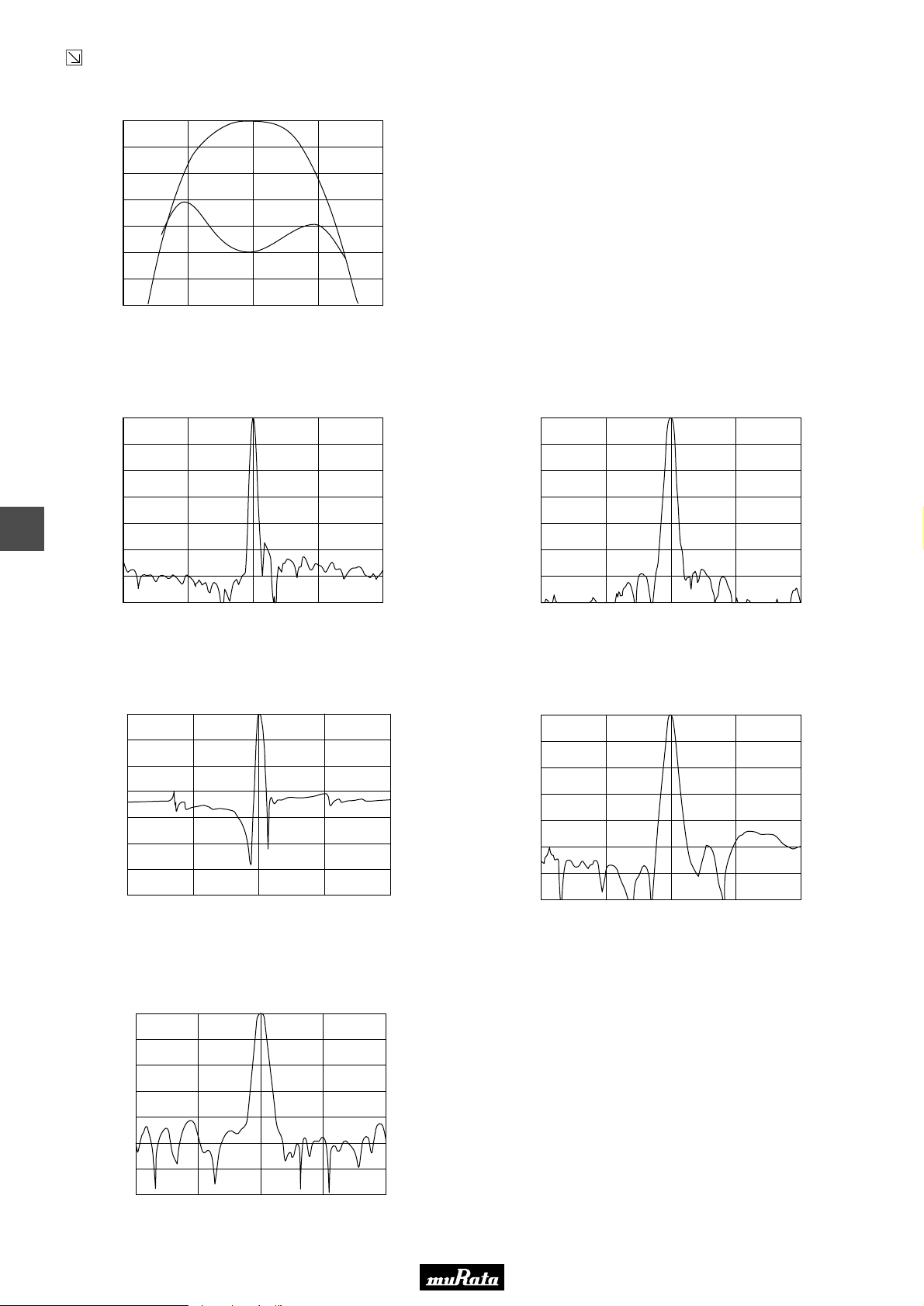
• This PDF catalog is downloaded from the website of Murata Manufacturing co., ltd. Therefore, it’s specifications are subject to change or our products in it may be discontinued without advance notice. Please check with our
!Note
• This PDF catalog has only typical specifications because there is no space for detailed specifications. Therefore, please approve our product specifications or transact the approval sheet for product specifications before ordering.
• Please read rating and !CAUTION (for storage, operating, rating, soldering, mounting and handling) in this catalog to prevent smoking and/or burning, etc.
!Note
sales representatives or product engineers before ordering.
• This catalog has only typical specifications because there is no space for detailed specifications. Therefore, please approve our product specifications or transact the approval sheet for product specifications before ordering.
Continued from the preceding page.
■ Frequency Characteristics
SFELF10M7KAH0-B0
0
1
2
3
4
Attenuation (dB)
5
6
7
10.70010.65010.600 10.750 10.800
Frequency (MHz)
8.0
7.5
7.0
6.5
6.0
G.D.T. (µsec.)
5.5
5.0
4.5
■ Frequency Characteristics (Spurious)
SFVLF10M7MF00-B0
0
10
20
30
8
40
Attenuation (dB)
50
60
70
8.700 9.700 10.700 11.700 12.700
Frequency (MHz)
0
10
20
30
40
Attenuation (dB)
50
60
70
8.700 9.700 10.700 11.700 12.700
SFVLF10M7LF00-B0
Frequency (MHz)
P50E.pdf
10.2.9
0
10
20
30
40
Attenuation (dB)
50
60
70
9.700
10.200
10.700
Frequency (MHz)
11.200
SFELF10M7KAH0-B0
0
10
20
30
40
Attenuation (dB)
50
60
70
SFKLF10M7NL00-B0
8.700 9.700 10.700 11.700 12.700
Frequency (MHz)
11.700
SFELF10M7LFTA-B0
0
10
20
30
40
Attenuation (dB)
50
60
70
8.700 9.700 10.700 11.700 12.700
Frequency (MHz)
30
Page 33
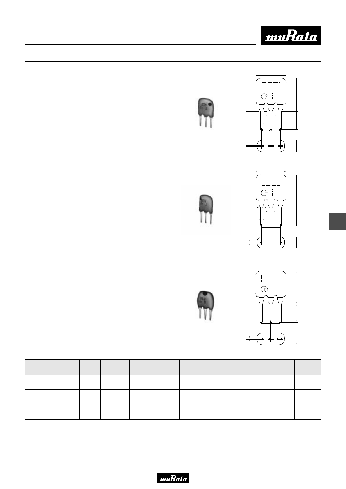
• This PDF catalog is downloaded from the website of Murata Manufacturing co., ltd. Therefore, it’s specifications are subject to change or our products in it may be discontinued without advance notice. Please check with our
!Note
• This PDF catalog has only typical specifications because there is no space for detailed specifications. Therefore, please approve our product specifications or transact the approval sheet for product specifications before ordering.
• Please read rating and !CAUTION (for storage, operating, rating, soldering, mounting and handling) in this catalog to prevent smoking and/or burning, etc.
!Note
sales representatives or product engineers before ordering.
• This catalog has only typical specifications because there is no space for detailed specifications. Therefore, please approve our product specifications or transact the approval sheet for product specifications before ordering.
CERAFILr (Filters/Traps/Discriminators) for Audio/Visual Equipment
CERAFILr 10.7MHz for FM-IF Tuners
7.0±2.0
SFELF10M7 series for FM-receivers are monolithic type
ceramic filters which use the thickness expander mode
of the piezoelectric ceramic.
As part of the environment protection activity, solder
for terminal plating and terminal-element connection
inside of ceramic filter contain no lead (Pb).
■ Features
1. Little dispersion of amplitude characteristics and
phase characteristics (G. D. T. characteristics)
2. The SFELF_G series is based on SFELF_FA00/GA00/HA00,
and it obtains high selectivity with low loss.
There is little dispersion of amplitude and GDT
characteristics, and low distortion rate can be
obtained.
3. The flatness of GDT is inspected for all products.
SFELF10M7HA0G-B0
SFELF10M7GA0G-B0
1.38±0.2
1.7±0.1
0.5±0.1
0.3±0.1
1.38±0.2
1.7±0.1
0.5±0.1
0.3±0.1
M A R K I N G
2.5±0.2
(3)
7.0±2.0
M A R K I N G
2.5±0.2
(3)
(2)
(2)
E I A J
C O D E
2.5±0.2
E I A J
C O D E
2.5±0.2
(1)
(1)
7.0±2.0
5.0±1.0
3.0±1.0
7.0±2.0
5.0±1.0
3.0±1.0
(1) : Input
(2) : Ground
(3) : Output
(in mm)
(1) : Input
(2) : Ground
(3) : Output
(in mm)
P50E.pdf
10.2.9
9
7.0±2.0
M A R K I N G
E I A J
C O D E
1.38±0.2
1.7±0.1
0.5±0.1
2.5±0.2
2.5±0.2
SFELF10M7FA0G-B0
Part Number
SFELF10M7HA0G-B0
SFELF10M7GA0G-B0
SFELF10M7FA0G-B0
Area of Attenuation: [within 20dB]
Area of Insertion Loss: at minimum loss point
Center frequency (fo) defined by the center of 3dB bandwidth.
For safety purposes, connect the output of filters to the IF amplifier through a D.C. blocking capacitor. Avoid applying a direct current to the output of ceramic filters.
The order quantity should be an integral multiple of the "Minimum Quantity" shown in the package page.
Center
Frequency
(fo) (MHz)
10.700
±30kHz
10.700
±30kHz
10.700
±30kHz
3dB
Bandwidth
(kHz)
Attenuation
(kHz)
Insertion Loss
(dB)
180 ±40kHz 520 max. 7.0 max.
230 ±50kHz 600 max. 7.0 max.
280 ±50kHz 650 max. 4.0 ±2.0dB
Spurious
Attenuation
(1) (dB)
40 min.
[within 9MHz to fo]
40 min.
[within 9MHz to fo]
30 min.
[within 9MHz to fo]
Spurious
Attenuation
(2) (dB)
40 min.
[within fo to 12MHz]
40 min.
[within fo to 12MHz]
30 min.
[within fo to 12MHz]
0.3±0.1
(3)
(2)
GDT Bandwidth
(kHz)
fo±45 min.
[within 0.5µsec.]
fo±60 min.
[within 0.5µsec.]
fo±85 min.
[within 0.5µsec.]
7.0±2.0
5.0±1.0
3.0±1.0
(1)
(1) : Input
(2) : Ground
(3) : Output
(in mm)
Input/Output
Impedance
(ohm)
330
330
330
31
Page 34
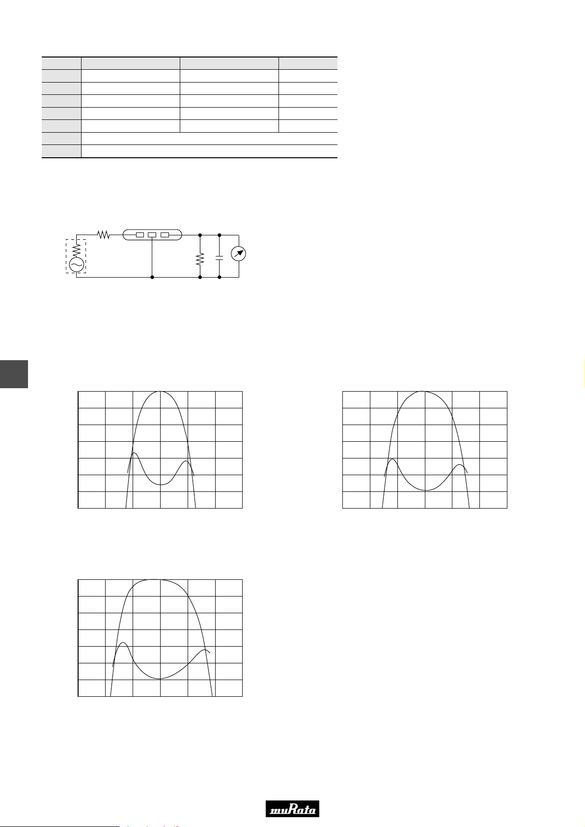
• This PDF catalog is downloaded from the website of Murata Manufacturing co., ltd. Therefore, it’s specifications are subject to change or our products in it may be discontinued without advance notice. Please check with our
!Note
• This PDF catalog has only typical specifications because there is no space for detailed specifications. Therefore, please approve our product specifications or transact the approval sheet for product specifications before ordering.
• Please read rating and !CAUTION (for storage, operating, rating, soldering, mounting and handling) in this catalog to prevent smoking and/or burning, etc.
!Note
sales representatives or product engineers before ordering.
• This catalog has only typical specifications because there is no space for detailed specifications. Therefore, please approve our product specifications or transact the approval sheet for product specifications before ordering.
■ Standard Center Frequency Rank Code
CODE
D
B
A
C
E
Z
M
30kHz Step
10.64MHz±30kHz
10.67MHz±30kHz
10.70MHz±30kHz
10.73MHz±30kHz
10.76MHz±30kHz
25kHz Step
10.650MHz±25kHz
10.675MHz±25kHz
10.700MHz±25kHz
10.725MHz±25kHz
10.750MHz±25kHz
Combination A, B, C, D, E
Combination A, B, C
Color Code
Black
Blue
Red
Orange
White
■ Test Circuit
P50E.pdf
10.2.9
(1) (2) (3)
RF
C
R2
Voltmeter
(1) : Input
(2) : Ground
(3) : Output
S.S.G
1
R
Rg
Rg + R1 = R2 = Input and Output Impedance
C = 10pF (Including stray capacitance and input
capacitance of RF voltmeter.)
■ Frequency Characteristics
9
0
1
2
3
4
Attenuation (dB)
5
6
7
10.400 10.500 10.600 10.700 10.800 10.900 11.000
SFELF10M7HA0G-B0
Frequency (MHz)
SFELF10M7GA0G-B0
6.5
6.0
5.5
5.0
4.5
G.D.T. (µsec.)
4.0
3.5
3.0
0
1
2
3
4
Attenuation (dB)
5
6
7
10.400 10.500 10.600 10.700 10.800 10.900 11.000
Frequency (MHz)
6.0
5.5
5.0
4.5
4.0
G.D.T. (µsec.)
3.5
3.0
2.5
SFELF10M7FA0G-B0
0
1
2
3
4
Attenuation (dB)
5
6
7
10.400 10.500 10.600 10.700 10.800 10.900 11.000
Frequency (MHz)
32
5.5
5.0
4.5
4.0
3.5
G.D.T. (µsec.)
3.0
2.5
2.0
Page 35
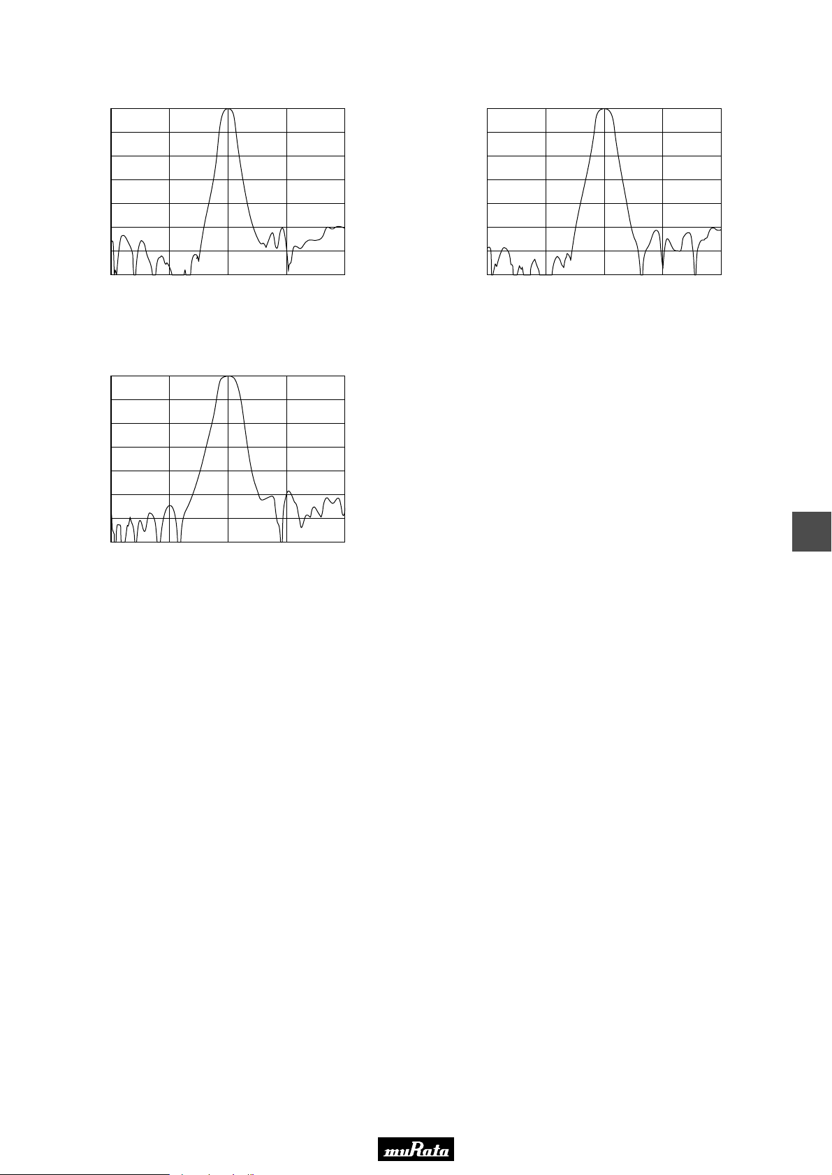
• This PDF catalog is downloaded from the website of Murata Manufacturing co., ltd. Therefore, it’s specifications are subject to change or our products in it may be discontinued without advance notice. Please check with our
!Note
• This PDF catalog has only typical specifications because there is no space for detailed specifications. Therefore, please approve our product specifications or transact the approval sheet for product specifications before ordering.
• Please read rating and !CAUTION (for storage, operating, rating, soldering, mounting and handling) in this catalog to prevent smoking and/or burning, etc.
!Note
sales representatives or product engineers before ordering.
• This catalog has only typical specifications because there is no space for detailed specifications. Therefore, please approve our product specifications or transact the approval sheet for product specifications before ordering.
■ Frequency Characteristics (Spurious)
SFELF10M7HA0G-B0
0
10
20
30
40
Attenuation (dB)
50
60
70
8.700 9.700 10.700 11.700 12.700
Frequency (MHz)
SFELF10M7FA0G-B0
0
10
20
30
40
Attenuation (dB)
50
60
70
8.700 9.700 10.700 11.700 12.700
Frequency (MHz)
0
10
20
30
40
Attenuation (dB)
50
60
70
8.700 9.700 10.700 11.700 12.700
SFELF10M7GA0G-B0
Frequency (MHz)
P50E.pdf
10.2.9
9
33
Page 36
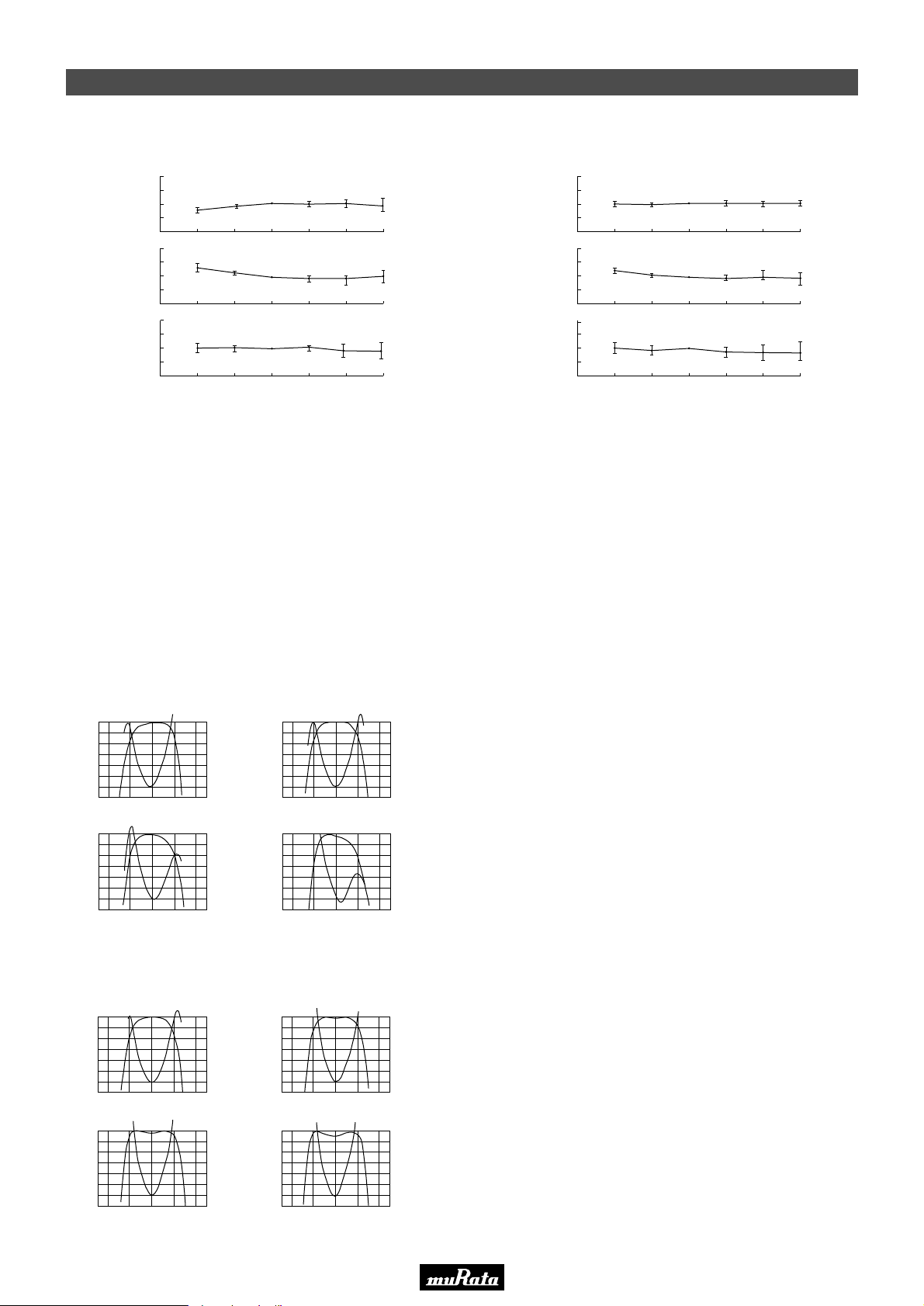
• This PDF catalog is downloaded from the website of Murata Manufacturing co., ltd. Therefore, it’s specifications are subject to change or our products in it may be discontinued without advance notice. Please check with our
!Note
• This PDF catalog has only typical specifications because there is no space for detailed specifications. Therefore, please approve our product specifications or transact the approval sheet for product specifications before ordering.
• Please read rating and !CAUTION (for storage, operating, rating, soldering, mounting and handling) in this catalog to prevent smoking and/or burning, etc.
!Note
sales representatives or product engineers before ordering.
• This catalog has only typical specifications because there is no space for detailed specifications. Therefore, please approve our product specifications or transact the approval sheet for product specifications before ordering.
CERAFILr 10.7MHz Related Data on Lead Type
■ Temperature Characteristics
W40
W20
Y20
Variation (kHz)Variation (dB)Variation (kHz)
Y40
W2
W1
Y1
Y2
W40
W20
Y20
Y40
SFELF10M7GA00-B0
Center frequency
0
Y20
Insertion loss
0
Y20
3dB Bandwidth
0
Y20
0 W20
Temperature (˚C)
0 W20
Temperature (˚C)
0 W20
Temperature (˚C)
W40 W60 W80
W40 W60 W80
W40 W60 W80
W40
W20
Y20
Variation (kHz)Variation (dB)Variation (kHz)
Y40
W2
W1
Y1
Y2
W40
W20
Y20
Y40
■ Matching Conditions
•When using ceramic filters, it is most important to
match the input/output load to impedance 330 ohm
(SFELF10M7DF00-B0 is 470 ohm and
SFKLF10M7NL00-B0 is 600 ohm matching).
Waveform symmetry is damaged when reactance is added
to the input/output load.
•Two ceramic filters directly connected can be used
9
for high selectivity. For reducing waveform
variation, it is recommended to input a buffer AMP
between ceramic filters.
•The SFELF10M7 series are of input/output symmetric
structure so that in theory there is no input/output
directionality. Actual circuits may use different
input/output loading conditions (for example,
mismatched impedance) or capacitance load. In such
cases, the waveform will be a little changed by the
direction of the input/output of the ceramic filters.
SFELF10M7HA00-B0
Center frequency
0
Y20
Insertion loss
0
Y20
3dB Bandwidth
0
Y20
0 W20 W40 W60 W80
Temperature (˚C)
0 W20 W40 W60 W80
Temperature (˚C)
0 W20 W40 W60 W80
Temperature (˚C)
P50E.pdf
10.2.9
■ Loaded Resistance and Waveform (Rg+R1=330 ohm)
R2=220Ω R2=330Ω
0 1.2
1
2
3
4
5
Attenuation (dB)Attenuation (dB)
6
7
0 1.2
1
2
3
4
5
6
7
10.7 10.8 10.910.610.5
Frequency (MHz)
2=560Ω R2=1kΩ
R
10.7 10.8 10.910.610.5
Frequency (MHz)
SFELF10M7GA00-B0
1.0
0.8
0.6
0.4
0.2
0
1.0
0.8
0.6
0.4
0.2
0
0 1.2
1
2
3
4
5
Attenuation (dB)Attenuation (dB)
6
7
Group Delay Time (µsec.)Group Delay Time (µsec.)
0 1.2
1
2
3
4
5
6
7
10.7 10.8 10.910.610.5
Frequency (MHz)
10.7 10.8 10.910.610.5
Frequency (MHz)
1.0
0.8
0.6
0.4
0.2
0
Group Delay Time (µsec.)Group Delay Time (µsec.)
1.0
0.8
0.6
0.4
0.2
0
■ Loaded Capacitance and Waveform (Rg+R1=R2=330 ohm)
C=10pF C=33pF
0 1.2
1
2
3
4
5
Attenuation (dB)Attenuation (dB)
6
7
0 1.2
1
2
3
4
5
6
7
10.7 10.8 10.910.610.5
Frequency (MHz)
C=56pF C=82pF
10.7 10.8 10.910.610.5
Frequency (MHz)
SFELF10M7HA00-B0
1.0
0.8
0.6
0.4
0.2
0
1.0
0.8
0.6
0.4
0.2
0
0 1.2
1
2
3
4
5
Attenuation (dB)Attenuation (dB)
6
7
Group Delay Time (µsec.)Group Delay Time (µsec.)
0 1.2
1
2
3
4
5
6
7
10.7 10.8 10.910.610.5
Frequency (MHz)
10.7 10.8 10.910.610.5
Frequency (MHz)
1.0
0.8
0.6
0.4
0.2
0
Group Delay Time (µsec.)Group Delay Time (µsec.)
1.0
0.8
0.6
0.4
0.2
0
34
Page 37
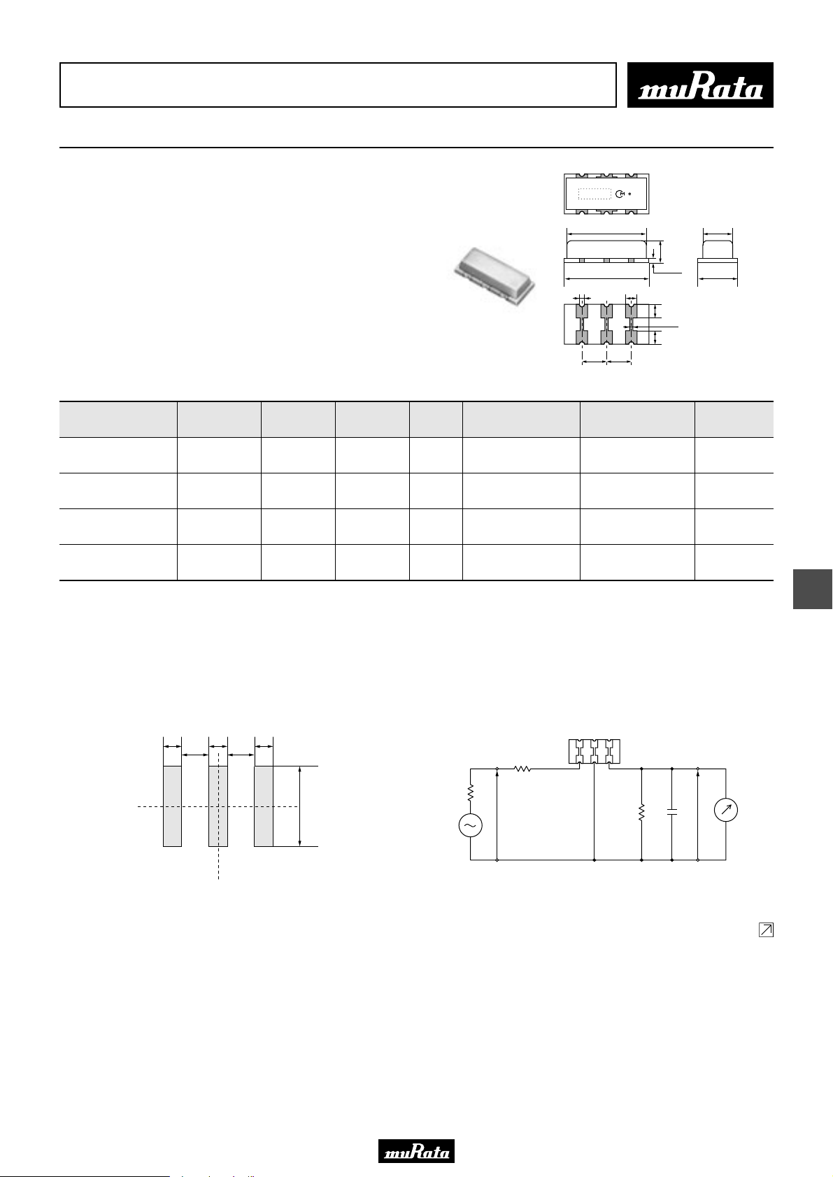
• This PDF catalog is downloaded from the website of Murata Manufacturing co., ltd. Therefore, it’s specifications are subject to change or our products in it may be discontinued without advance notice. Please check with our
!Note
• This PDF catalog has only typical specifications because there is no space for detailed specifications. Therefore, please approve our product specifications or transact the approval sheet for product specifications before ordering.
• Please read rating and !CAUTION (for storage, operating, rating, soldering, mounting and handling) in this catalog to prevent smoking and/or burning, etc.
!Note
sales representatives or product engineers before ordering.
• This catalog has only typical specifications because there is no space for detailed specifications. Therefore, please approve our product specifications or transact the approval sheet for product specifications before ordering.
CERAFILr (Filters/Traps/Discriminators) for Audio/Visual Equipment
CERAFILr 4.5-6.5MHz Chip Type SFSKA Series
SMD ceramic filter SFSKA_CF is a small and thin SMD
filter sealed with a metal cap.
Recommended for LCD-TVs, and small and thin tuners.
■ Features
1. High attenuation outside bandwidth
2. Small and thin package
3. Reflow-solderable
7.9±0.2 3.0±0.1
1.8±0.2
8.5±0.2
0.6±0.2 1.0±0.1
(1) (2) (3)
2.5±0.2 2.5±0.2
0.5±0.1
1.3±0.2
0.3±0.1
1.3±0.2
3.8±0.2
(1) : Input
(2) : Ground
(3) : Output
P50E.pdf
10.2.9
(in mm)
Part Number
Nominal Center
Frequency (fn)
(MHz)
SFSKA4M50CF00-R3 4.500 fn±60 min. 600 max. 6.0 max.
SFSKA5M50CF00-R3 5.500 fn±60 min. 600 max. 6.0 max.
SFSKA6M00CF00-R3 6.000 fn±60 min. 600 max. 6.0 max.
SFSKA6M50CF00-R3 6.500 fn±60 min. 600 max. 6.0 max.
Area of Insertion Loss: at minimum loss point
For safety purposes, connect the output of filters to the IF amplifier through a D.C. blocking capacitor. Avoid applying a direct current to the output of ceramic filters.
The order quantity should be an integral multiple of the "Minimum Quantity" shown in the package page.
■ Standard Land Pattern Dimensions
3dB
Bandwidth
(kHz)
20dB
Bandwidth
(kHz)
Insertion
Loss
(dB)
■ Test Circuit
Spurious
Attenuation(1)
(dB)
20 min.
[within 0 to fn]
25 min.
[within 0 to fn]
25 min.
[within 0 to fn]
25 min.
[within 0 to fn]
Spurious
Attenuation(2)
(dB)
15 min.
[within fn to 7.0MHz]
15 min.
[within fn to 7.0MHz]
15 min.
[within fn to 7.5MHz]
15 min.
[within fn to 8.5MHz]
SFSKA4M50CF00-R1
1.0 1.0
1.5 1.5
1.0
R1
4.8
Rg
E1
S.S.G.
(1) (2) (3)
R2
C2
Input/Output
Impedance
(ohm)
1000
600
470
470
E2
RF
Voltmeter
10
(in mm)
R1+Rg=R2=1000Ω ±5%, Rg=50Ω
C2=10pF (Including stray capacitance and Input capacitance of RF Voltmeter)
E1:S.S.G. Output voltage
Continued on the following page.
(1) :
(2) :
(3) :
Input
Ground
Output
35
Page 38
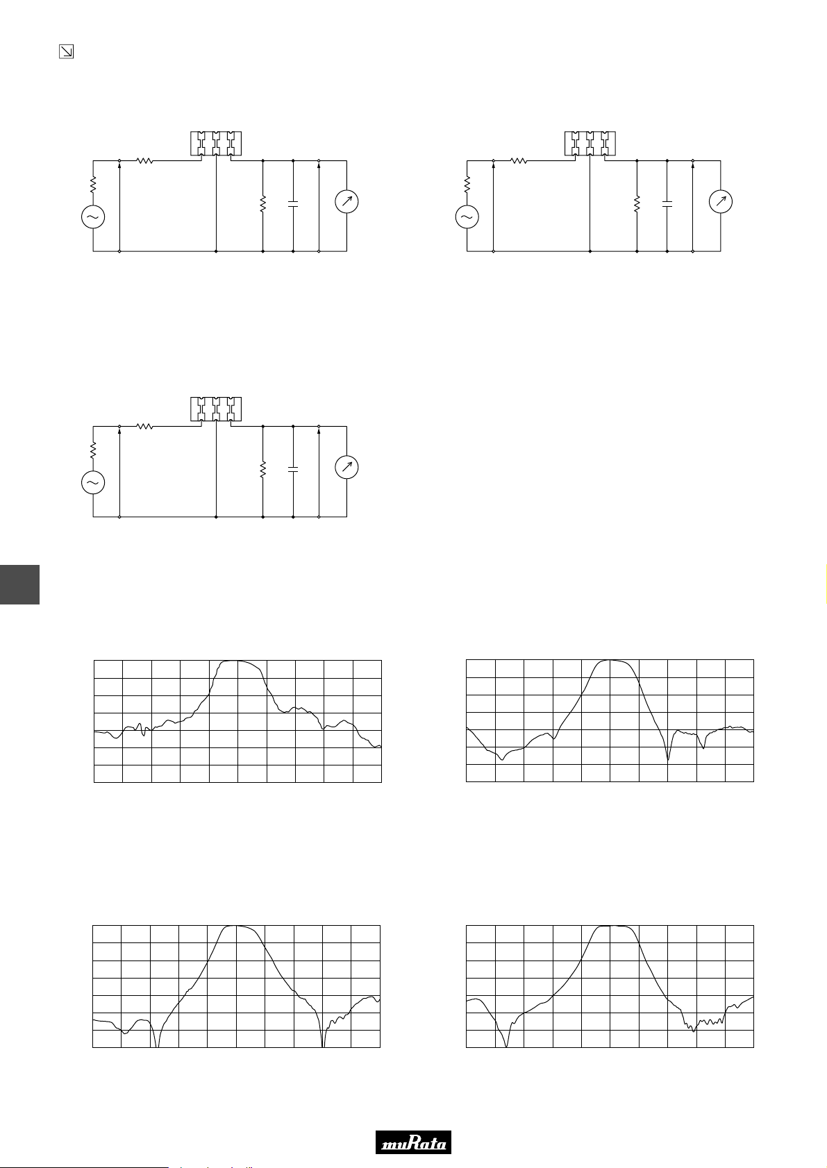
• This PDF catalog is downloaded from the website of Murata Manufacturing co., ltd. Therefore, it’s specifications are subject to change or our products in it may be discontinued without advance notice. Please check with our
!Note
• This PDF catalog has only typical specifications because there is no space for detailed specifications. Therefore, please approve our product specifications or transact the approval sheet for product specifications before ordering.
• Please read rating and !CAUTION (for storage, operating, rating, soldering, mounting and handling) in this catalog to prevent smoking and/or burning, etc.
!Note
sales representatives or product engineers before ordering.
• This catalog has only typical specifications because there is no space for detailed specifications. Therefore, please approve our product specifications or transact the approval sheet for product specifications before ordering.
Continued from the preceding page.
■ Test Circuit
SFSKA5M50CF00-R1
SFSKA6M00CF00-R1
P50E.pdf
10.2.9
(1) (2) (3)
R1
Rg
E1
S.S.G.
R1+Rg=R2=600Ω ±5%, Rg=50Ω
C2=10pF (Including stray capacitance and Input capacitance of RF Voltmeter)
E1: S.S.G. Output voltage
SFSKA6M50CF00-R1
(1) (2) (3)
R1
Rg
E1
S.S.G.
R1+Rg=R2=470Ω ±5%, Rg=50Ω
C2=10pF (Including stray capacitance and Input capacitance of RF Voltmeter)
E1: S.S.G. Output voltage
(1) (2) (3)
R1
R2
R2
E2
C2
E2
C2
RF
Voltmeter
(1) :
(2) :
(3) :
RF
Voltmeter
(1) :
(2) :
(3) :
Input
Ground
Output
Input
Ground
Output
Rg
E1
S.S.G.
R1+Rg=R2=470Ω ±5%, Rg=50Ω
C2=10pF (Including stray capacitance and Input capacitance of RF Voltmeter)
E1: S.S.G. Output voltage
R2
E2
C2
RF
Voltmeter
(1) :
(2) :
(3) :
Input
Ground
Output
10
■ Frequency Characteristics
SFSKA4M50CF00-R1
0
10
20
30
40
Attenuation (dB)
50
60
70
3.5 3.93.7 4.1 4.5 4.9 5.34.3
Frequency (MHz)
SFSKA6M00CF00-R1
0
10
20
30
40
50
Attenuation (dB)
60
70
5.0 5.2 5.4 5.6 5.8 6.0 6.2 6.4 6.6 6.8 7.0
Frequency (MHz)
4.7
5.1 5.5
SFSKA5M50CF00-R1
0
10
20
30
40
50
Attenuation (dB)
60
70
4.5 4.7 4.9 5.1 5.3 5.5 5.7 5.9 6.1 6.3 6.5
Frequency (MHz)
SFSKA6M50CF00-R1
0
10
20
30
40
50
Attenuation (dB)
60
70
5.5 5.7 5.9 6.1 6.3 6.5 6.7 6.9 7.1 7.3 7.5
Frequency (MHz)
36
Page 39
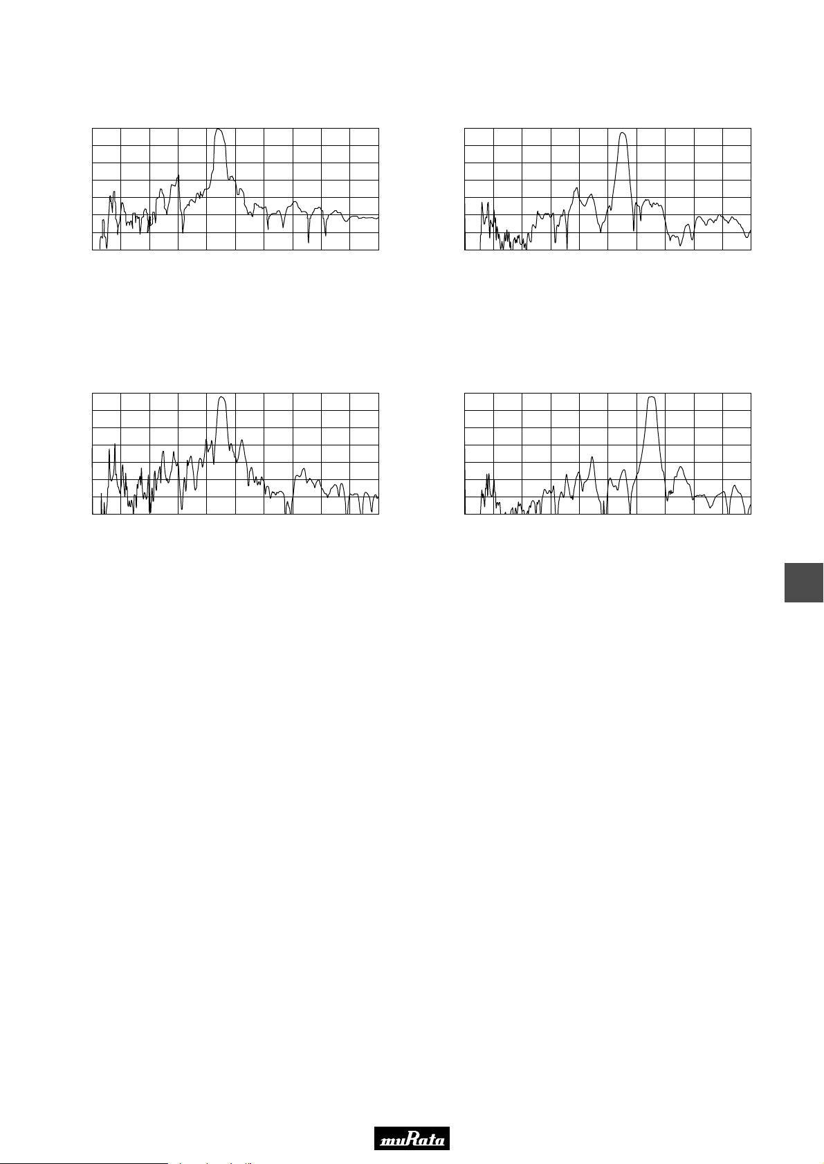
• This PDF catalog is downloaded from the website of Murata Manufacturing co., ltd. Therefore, it’s specifications are subject to change or our products in it may be discontinued without advance notice. Please check with our
!Note
• This PDF catalog has only typical specifications because there is no space for detailed specifications. Therefore, please approve our product specifications or transact the approval sheet for product specifications before ordering.
• Please read rating and !CAUTION (for storage, operating, rating, soldering, mounting and handling) in this catalog to prevent smoking and/or burning, etc.
!Note
sales representatives or product engineers before ordering.
• This catalog has only typical specifications because there is no space for detailed specifications. Therefore, please approve our product specifications or transact the approval sheet for product specifications before ordering.
■ Frequency Characteristics (Spurious)
SFSKA4M50CF00-R1
SFSKA5M50CF00-R1
P50E.pdf
10.2.9
0
10
20
30
40
50
Attenuation (dB)
60
70
0.0 2.0 4.0
Frequency (MHz)
6.0
8.0 10.0
SFSKA6M00CF00-R1
0
10
20
30
40
50
Attenuation (dB)
60
70
0 2.0 4.0 6.0 8.0 10.0
Frequency (MHz)
0
10
20
30
40
50
Attenuation (dB)
60
70
0 2.0 4.0 6.0 8.0 10.0
Frequency (MHz)
SFSKA6M50CF00-R1
0
10
20
30
40
50
Attenuation (dB)
60
70
0 2.0 4.0 6.0 8.0 10.0
Frequency (MHz)
10
37
Page 40
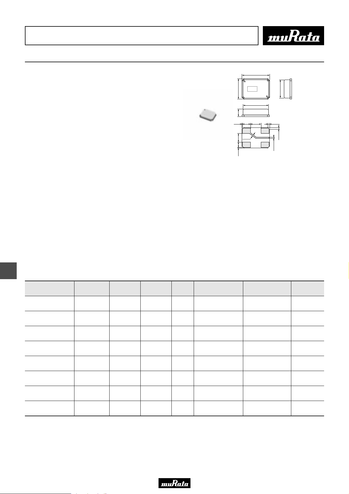
• This PDF catalog is downloaded from the website of Murata Manufacturing co., ltd. Therefore, it’s specifications are subject to change or our products in it may be discontinued without advance notice. Please check with our
!Note
• This PDF catalog has only typical specifications because there is no space for detailed specifications. Therefore, please approve our product specifications or transact the approval sheet for product specifications before ordering.
• Please read rating and !CAUTION (for storage, operating, rating, soldering, mounting and handling) in this catalog to prevent smoking and/or burning, etc.
!Note
sales representatives or product engineers before ordering.
• This catalog has only typical specifications because there is no space for detailed specifications. Therefore, please approve our product specifications or transact the approval sheet for product specifications before ordering.
CERAFILr (Filters/Traps/Discriminators) for Audio/Visual Equipment
CERAFILr 2.3-5.7MHz Chip Type SFSKB Series
5.2±0.1
The SFSKB series are SMD ceramic filters which are
suitable for IR head phone applications.
Center frequencies of 2.3, 2.8, 3.2, 3.8, 4.3, 4.8,
5.2, 5.7MHz are available.
Realized Small, thin and lightweight package,
compared with conventional LC filters.
It helps to compose multi channel circuit on one PCB.
No frequency adjustment is required on PCB and it
contributes reduction of production cost.
■ Features
1. SMD package in plastic emboss tape, available
for automatic placing.
2. They are slim, at only 1.5mm max. thickness,
and have a small mounting area (5.2x3.8mm) enabling
flexible PCB design.
3. Available for lead (Pb) free re-flow soldering process.
4. Operating temperature range: 0 to +70 (degree C)
Storage temperature range: -55 to +85 (degree C)
5. No frequency adjustment is required in production process.
6. Small, thin and lightweight package compared with
conventional LC filters
(0.1)
1.35±0.15
(1.6)
1.0±0.1
(0.1)
(4)
3.8±0.1
(3)
(4.93)
1.5±0.1
(3)
0.3±0.1
(4)
(2.0)
(1)
∗
(2)
(1)
(3.5)
(2)
Terminal Connection
(1) : Input
4-0.35
(2) : Output
(3) : Ground
(4) : Terminal for external
capacitor
4-0.35
∗
Tolerance unless otherwise
specified : ±0.1mm
0.25±0.1
( ) : Reference
P50E.pdf
10.2.9
: EIAJ Monthly Code
(in mm)
11
■ Applications
1. IR head phone
2. Set Top Box for satellite broadcasting
Part Number
Nominal Center
Frequency (fn)
(MHz)
SFSKB2M30GF00-R1 2.300 fn±75 min. 650 max. 6.0 max.
SFSKB2M80GF00-R1 2.800 fn±75 min. 650 max. 6.0 max.
SFSKB3M20FF00-R1 3.200 fn±75 min. 650 max. 6.0 max.
SFSKB3M80GF00-R1 3.800 fn±75 min. 650 max. 6.0 max.
SFSKB4M30GF00-R1 4.300 fn±75 min. 650 max. 6.0 max.
SFSKB4M80GF00-R1 4.800 fn±75 min. 650 max. 6.0 max.
SFSKB5M20GF00-R1 5.200 fn±75 min. 650 max. 6.0 max.
SFSKB5M70GF00-R1 5.700 fn±75 min. 650 max. 6.0 max.
For safety purposes, connect the output of filters to the IF amplifier through a D.C. blocking capacitor. Avoid applying a direct current to the output of ceramic filters.
The order quantity should be an integral multiple of the "Minimum Quantity" shown in the package page.
3dB
Bandwidth
(kHz)
20dB
Bandwidth
(kHz)
Insertion
Loss
(dB)
Spurious
Attenuation(1)
(dB)
25 min.
[within 1.3 to 1.8MHz]
25 min.
[within 1.8 to 2.3MHz]
30 min.
[within 2.2 to 2.8MHz]
30 min.
[within 2.8 to 3.2MHz]
30 min.
[within 3.3 to 3.8MHz]
30 min.
[within 3.8 to 4.3MHz]
30 min.
[within 4.2 to 4.8MHz]
30 min.
[within 4.7 to 5.2MHz]
Spurious
Attenuation(2)
(dB)
23 min.
[within 2.8 to 3.3MHz]
25 min.
[within 3.3 to 3.8MHz]
30 min.
[within 3.8 to 4.2MHz]
30 min.
[within 4.3 to 4.8MHz]
30 min.
[within 4.8 to 5.3MHz]
30 min.
[within 5.2 to 5.8MHz]
30 min.
[within 5.7 to 6.2MHz]
30 min.
[within 6.2 to 6.7MHz]
Input/Output
Impedance
(ohm)
1000
1000
1000
1000
1000
1000
1000
1000
38
Page 41
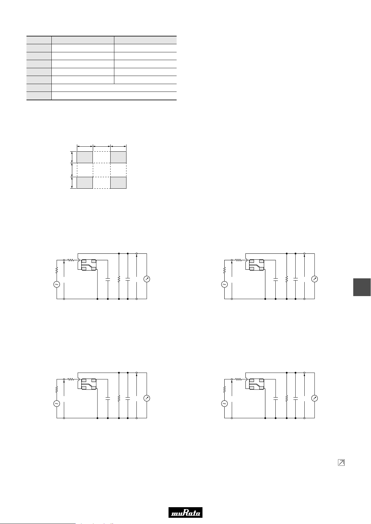
• This PDF catalog is downloaded from the website of Murata Manufacturing co., ltd. Therefore, it’s specifications are subject to change or our products in it may be discontinued without advance notice. Please check with our
!Note
• This PDF catalog has only typical specifications because there is no space for detailed specifications. Therefore, please approve our product specifications or transact the approval sheet for product specifications before ordering.
• Please read rating and !CAUTION (for storage, operating, rating, soldering, mounting and handling) in this catalog to prevent smoking and/or burning, etc.
!Note
sales representatives or product engineers before ordering.
• This catalog has only typical specifications because there is no space for detailed specifications. Therefore, please approve our product specifications or transact the approval sheet for product specifications before ordering.
■ Standard Center Frequency Rank Code
CODE
D
B
A
C
E
Z
M
30kHz Step
10.64MHz±30kHz
10.67MHz±30kHz
10.70MHz±30kHz
10.73MHz±30kHz
10.76MHz±30kHz
Combination A, B, C, D, E
Combination A, B, C
25kHz Step
10.650MHz±25kHz
10.675MHz±25kHz
10.700MHz±25kHz
10.725MHz±25kHz
10.750MHz±25kHz
■ Standard Land Pattern Dimensions
1.8 2.0 1.8
1.3 1.6 1.3
P50E.pdf
10.2.9
■ Test Circuit
SFSKB2M30GF00-R1/SFSKB3MZ0GF00-R1
R1
Rg
S.S.G.
R1+Rg=R2=1.0kΩ
Cc=22pF±5%
C2=10pF (Including stray capacitance and
Input capacitance of RF Voltmeter)
E1 : S.S.G. S.S.G. Output Voltage
E1
SFSKB4M30GF00-R1/SFSKB5M70GF00-R1
R1
(in mm)
SFSKB2M80GF00-R1/SFSKB3M20FF00-R1
(1)
(4)
(2)
(3)
Cc
C2
R2
RF
E2
Voltmeter
S.S.G.
R1
(1)
(4)
Rg
(2)
(3)
E1
Cc
C2
R2
RF
E2
Voltmeter
11
R1+Rg=R2=1.0kΩ
(1) : Input
(2) : Output
(3) : Ground
(4) : Terminal for external capacitor
(1)
(4)
Cc=39pF±5%
C2=10pF (Including stray capacitance and
Input capacitance of RF Voltmeter)
E1 : S.S.G. S.S.G. Output Voltage
SFSKB4M80GF00-R1
R1
(1)
(4)
(1) : Input
(2) : Output
(3) : Ground
(4) : Terminal for external capacitor
Rg
S.S.G.
R1+Rg=R2=1.0kΩ
Cc=33pF±5%
C2=10pF (Including stray capacitance and
Input capacitance of RF Voltmeter)
E1 : S.S.G. S.S.G. Output Voltage
(2)
(3)
E1
Cc
C2
R2
(1) : Input
(2) : Output
(3) : Ground
(4) : Terminal for external capacitor
Rg
RF
E2
Voltmeter
S.S.G.
R1+Rg=R2=1.0kΩ
Cc=15pF±5%
C2=10pF (Including stray capacitance and
Input capacitance of RF Voltmeter)
E1 : S.S.G. S.S.G. Output Voltage
(2)
(3)
E1
Cc
C2
R2
(1) : Input
(2) : Output
(3) : Ground
(4) : Terminal for external capacitor
RF
E2
Voltmeter
Continued on the following page.
39
Page 42
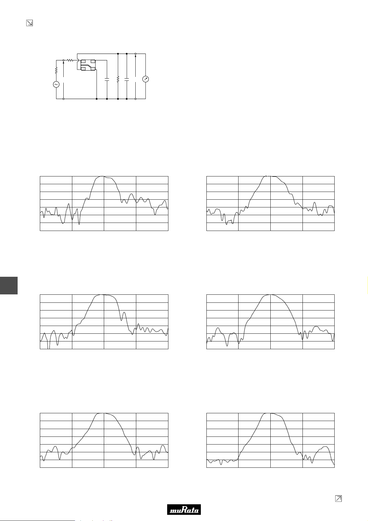
• This PDF catalog is downloaded from the website of Murata Manufacturing co., ltd. Therefore, it’s specifications are subject to change or our products in it may be discontinued without advance notice. Please check with our
!Note
• This PDF catalog has only typical specifications because there is no space for detailed specifications. Therefore, please approve our product specifications or transact the approval sheet for product specifications before ordering.
• Please read rating and !CAUTION (for storage, operating, rating, soldering, mounting and handling) in this catalog to prevent smoking and/or burning, etc.
!Note
sales representatives or product engineers before ordering.
• This catalog has only typical specifications because there is no space for detailed specifications. Therefore, please approve our product specifications or transact the approval sheet for product specifications before ordering.
Continued from the preceding page.
■ Test Circuit
SFSKB5M20GF00-R1
R1
(1)
(4)
P50E.pdf
10.2.9
Rg
S.S.G.
R1+Rg=R2=1.0kΩ
Cc=27pF±5%
C2=10pF (Including stray capacitance and
Input capacitance of RF Voltmeter)
E1 : S.S.G. S.S.G. Output Voltage
(2)
(3)
E1
Cc
C2
R2
E2
(1) : Input
(2) : Output
(3) : Ground
(4) : Terminal for external capacitor
■ Frequency Characteristics
SFSKB2M30GF00-R1
0
10
20
30
40
Attenuation (dB)
50
60
70
1.300 2.3001.800 2.800 3.300
Frequency (MHz)
RF
Voltmeter
SFSKB2M80GF00-R1
0
10
20
30
40
Attenuation (dB)
50
60
70
1.800 2.8002.300 3.300 3.800
Frequency (MHz)
11
SFSKB3M20FF00-R1
0
10
20
30
40
Attenuation (dB)
50
60
70
2.200 3.2002.700 3.700 4.200
Frequency (MHz)
SFSKB4M30GF00-R1
0
10
20
30
40
Attenuation (dB)
50
60
70
3.300 4.3003.800 4.800 5.300
Frequency (MHz)
SFSKB3M80GF00-R1
0
10
20
30
40
Attenuation (dB)
50
60
70
2.800 3.8003.300 4.300 4.800
Frequency (MHz)
SFSKB4M80GF00-R1
0
10
20
30
40
Attenuation (dB)
50
60
70
3.800 4.8004.300 5.300 5.800
Frequency (MHz)
40
Continued on the following page.
Page 43
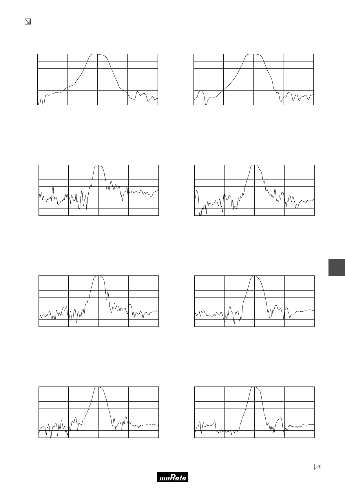
• This PDF catalog is downloaded from the website of Murata Manufacturing co., ltd. Therefore, it’s specifications are subject to change or our products in it may be discontinued without advance notice. Please check with our
!Note
• This PDF catalog has only typical specifications because there is no space for detailed specifications. Therefore, please approve our product specifications or transact the approval sheet for product specifications before ordering.
• Please read rating and !CAUTION (for storage, operating, rating, soldering, mounting and handling) in this catalog to prevent smoking and/or burning, etc.
!Note
sales representatives or product engineers before ordering.
• This catalog has only typical specifications because there is no space for detailed specifications. Therefore, please approve our product specifications or transact the approval sheet for product specifications before ordering.
Continued from the preceding page.
■ Frequency Characteristics
SFSKB5M20GF00-R1
SFSKB5M70GF00-R1
P50E.pdf
10.2.9
0
10
20
30
40
Attenuation (dB)
50
60
70
4.200 5.2004.700 5.700 6.200
Frequency (MHz)
■ Frequency Characteristics (Spurious)
SFSKB2M30GF00-R1
0
10
20
30
40
50
Attenuation (dB)
60
70
0.300 1.300 2.300
Frequency (MHz)
3.300
4.300
0
10
20
30
40
Attenuation (dB)
50
60
70
4.700 5.7005.200 6.200 6.700
Frequency (MHz)
SFSKB2M80GF00-R1
0
10
20
30
40
50
Attenuation (dB)
60
70
0.800 1.800 2.800
Frequency (MHz)
3.800
4.800
SFSKB3M20FF00-R1
0
10
20
30
40
50
Attenuation (dB)
60
70
1.200 2.200 3.200
SFSKB4M30GF00-R1
0
10
20
30
40
50
Attenuation (dB)
60
70
2.300 3.300 4.300
Frequency (MHz)
Frequency (MHz)
4.200
5.300
5.200
6.300
SFSKB3M80GF00-R1
0
10
20
30
40
50
Attenuation (dB)
60
70
1.800 2.800 3.800
SFSKB4M80GF00-R1
0
10
20
30
40
50
Attenuation (dB)
60
70
2.800 3.800 4.800
Frequency (MHz)
Frequency (MHz)
4.800
5.800
11
5.800
6.800
Continued on the following page.
41
Page 44
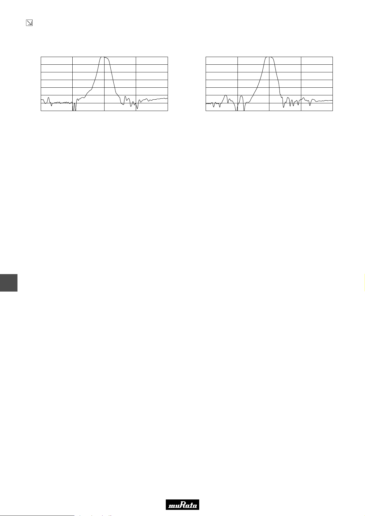
• This PDF catalog is downloaded from the website of Murata Manufacturing co., ltd. Therefore, it’s specifications are subject to change or our products in it may be discontinued without advance notice. Please check with our
!Note
• This PDF catalog has only typical specifications because there is no space for detailed specifications. Therefore, please approve our product specifications or transact the approval sheet for product specifications before ordering.
• Please read rating and !CAUTION (for storage, operating, rating, soldering, mounting and handling) in this catalog to prevent smoking and/or burning, etc.
!Note
sales representatives or product engineers before ordering.
• This catalog has only typical specifications because there is no space for detailed specifications. Therefore, please approve our product specifications or transact the approval sheet for product specifications before ordering.
Continued from the preceding page.
■ Frequency Characteristics (Spurious)
SFSKB5M20GF00-R1
SFSKB5M70GF00-R1
P50E.pdf
10.2.9
0
10
20
30
40
50
Attenuation (dB)
60
70
3.200 4.200 5.200
Frequency (MHz)
6.200
7.200
0
10
20
30
40
50
Attenuation (dB)
60
70
3.700 4.700 5.700
Frequency (MHz)
6.700
7.700
11
42
Page 45
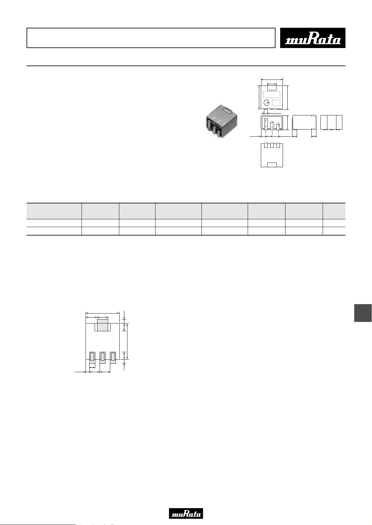
• This PDF catalog is downloaded from the website of Murata Manufacturing co., ltd. Therefore, it’s specifications are subject to change or our products in it may be discontinued without advance notice. Please check with our
!Note
• This PDF catalog has only typical specifications because there is no space for detailed specifications. Therefore, please approve our product specifications or transact the approval sheet for product specifications before ordering.
• Please read rating and !CAUTION (for storage, operating, rating, soldering, mounting and handling) in this catalog to prevent smoking and/or burning, etc.
!Note
sales representatives or product engineers before ordering.
• This catalog has only typical specifications because there is no space for detailed specifications. Therefore, please approve our product specifications or transact the approval sheet for product specifications before ordering.
CERAFILr (Filters/Traps/Discriminators) for Audio/Visual Equipment
CERAFILr 455kHz Chip Type SFPKA Series
7.0±0.3
3.0±0.3
SFPKA series for AM use is one of the most
1.5±0.3
7.5±0.3
MARKING
EIAJ
CODE
0.9±0.1
2.0±0.3
(1) (2) (3)
8.4 max.
5.0 max.
2.0±0.3
1.5±0.3 1.6±0.3
recommendable intermediate filters, having such
distinctive features as high selectivity, high
stability and adjustment-free operation.
Additionally its easy matching with IC helps create an
easy circuit design.
■ Features
1. The filters are mountable by automatic placers
and can be reflow soldered and withstand
washing.
2. The filters are wide bandwidth and high
selectivity. So they are suitable for car radio
and multi-band radio.
Connection
(1) : Input
(2) : Ground
(3) : Output
(in mm)
P50E.pdf
10.2.9
Part Number
Center
Frequency (fo)
(kHz)
6dB
Bandwidth
(kHz)
Selectivity (-)
(dB)
Selectivity (+)
(dB)
Insertion
Loss
(dB)
Input/Output
Impedance
(ohm)
SFPKA450KH1A-R1 450.0 ±1.0kHz fn±3.0 min. 40 min.[fn-9kHz] 40 min.[fn+9kHz] 6.0 max. 2000 4
SFPKA450KG1A-R1 450.0 ±1.0kHz fn±4.5 min. 40 min.[fn-10kHz] 40 min.[fn+10kHz] 6.0 max. 1500 4
Area of Insertion Loss: at minimum loss point
Center frequency (fo) is defined by the center of 6dB bandwidth.
(fn) means nominal center frequency (450kHz).
For safety purposes, connect the output of filters to the IF amplifier through a D.C. blocking capacitor. Avoid applying a direct current to the output of ceramic filters.
The order quantity should be an integral multiple of the "Minimum Quantity" shown in the package page.
■ Standard Land Pattern Dimensions
6.95
2.02.475
1.1
0.925 2.0 2.0
0.80.9
1.61.55
7.45
(in mm)
Element
12
43
Page 46
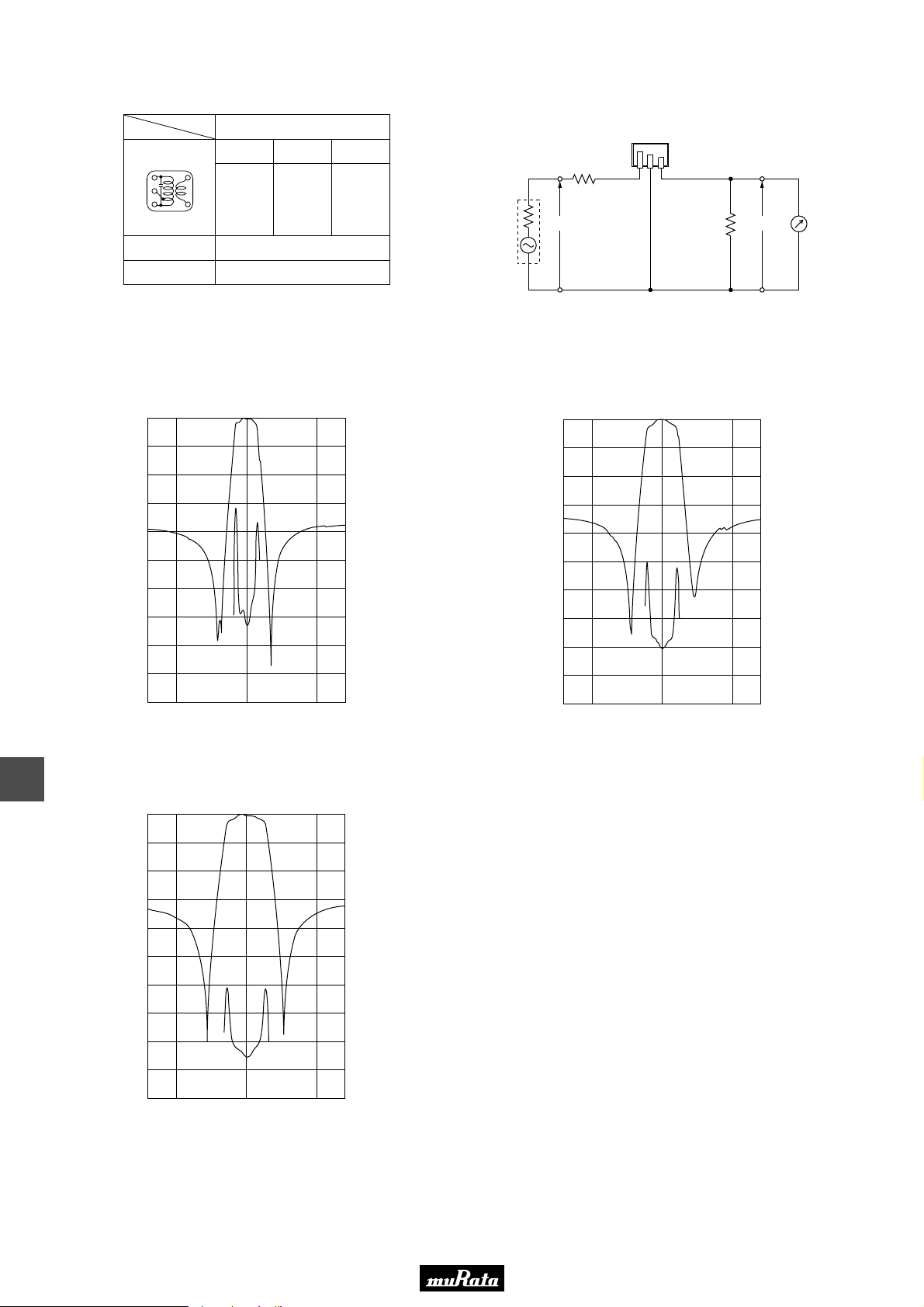
• This PDF catalog is downloaded from the website of Murata Manufacturing co., ltd. Therefore, it’s specifications are subject to change or our products in it may be discontinued without advance notice. Please check with our
!Note
• This PDF catalog has only typical specifications because there is no space for detailed specifications. Therefore, please approve our product specifications or transact the approval sheet for product specifications before ordering.
• Please read rating and !CAUTION (for storage, operating, rating, soldering, mounting and handling) in this catalog to prevent smoking and/or burning, etc.
!Note
sales representatives or product engineers before ordering.
• This catalog has only typical specifications because there is no space for detailed specifications. Therefore, please approve our product specifications or transact the approval sheet for product specifications before ordering.
P50E.pdf
10.2.9
■ Recommended IFT
No load Qu
Type
(1)—(2) (2)—(3) (4)—(6)
60T 125T 28T
(6)
Item
Winding Specification
S(3) (4)S
(2)
(1)
(Bottom view)
Tuning Capacitance
• Matching of CERAFILr SFPKA series with IFT is decided by the Qu of IFT
and IFT secondary side impedance, |Z2|. Set the Qu at about 40 because
a Qu value which is too high (e.g.,90) may produce ripple in the waveform.
It is recommended to match the impedance of |Z2| with that of the
CERAFILr.
■ Frequency Characteristics
SFPKA450KH1A-R1
0
10
20
30
40
SFPKA
40
180pF
400
360
320
280
240
■ Test Circuit
S.S.G.
0dBm
Rg
E1
0
10
20
30
40
R1
(1)
(2)
Rg+R1=R2=Input/Output Impedance
E1 : S.S.G. Output Voltage
SFPKA450KG1A-R1
(3)
400
360
320
280
240
RF Voltmeter
(1) : Input
(2) : Ground
(3) : Output
R2 E2
12
50
Attenuation (dB)
60
70
80
90
100
425 450 475
Frequency (kHz)
200
160
120
80
40
0
50
G.D.T. (µsec.)
Attenuation (dB)
60
70
80
90
100
425 450 475
Frequency (kHz)
200
160
120
80
40
0
G.D.T. (µsec.)
SFPKA450KF4A-R1
0
10
20
30
40
50
Attenuation (dB)
60
400
360
320
280
240
200
160
G.D.T. (µsec.)
44
70
80
90
100
425 450 475
Frequency (kHz)
120
80
40
0
Page 47
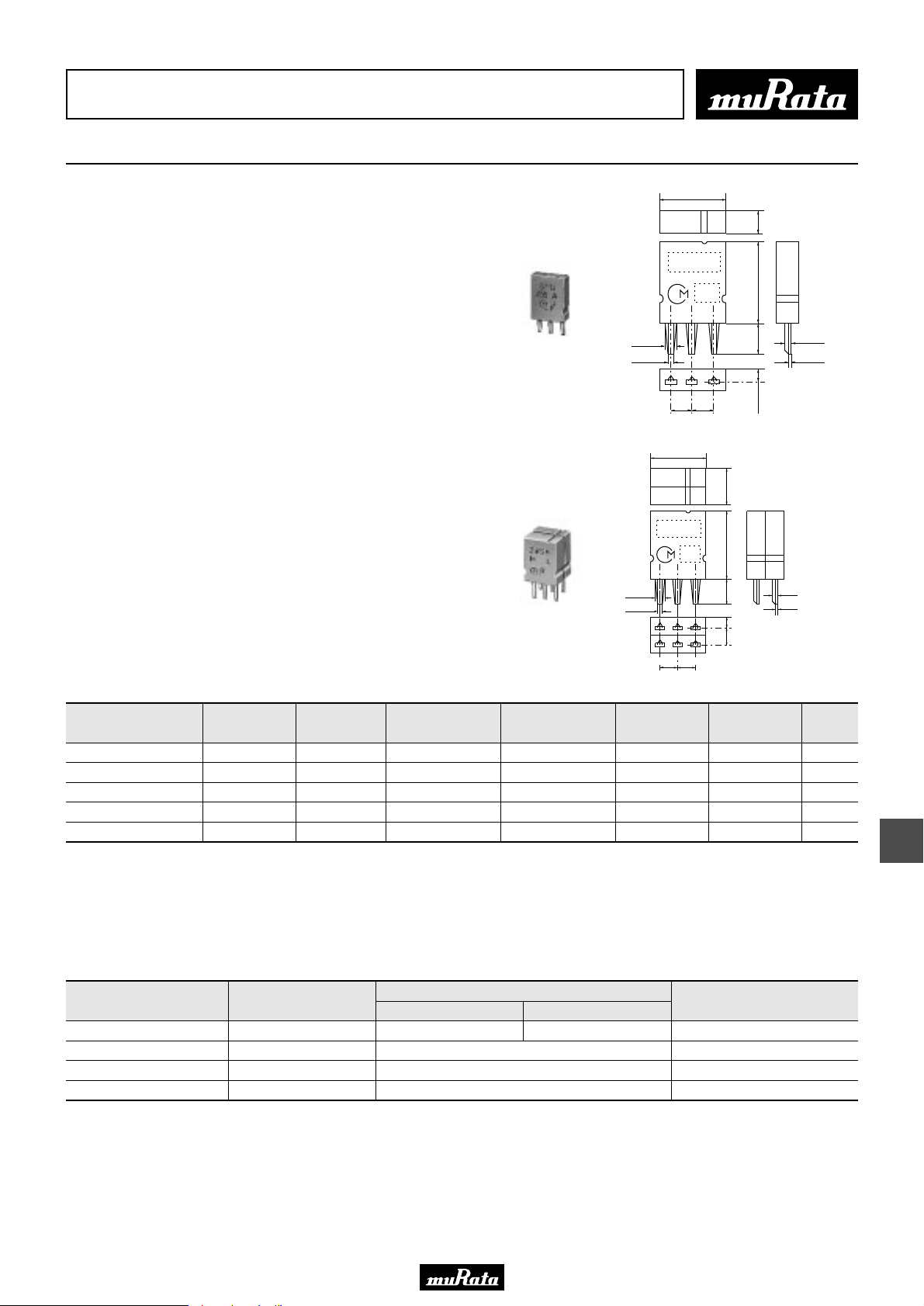
• This PDF catalog is downloaded from the website of Murata Manufacturing co., ltd. Therefore, it’s specifications are subject to change or our products in it may be discontinued without advance notice. Please check with our
!Note
• This PDF catalog has only typical specifications because there is no space for detailed specifications. Therefore, please approve our product specifications or transact the approval sheet for product specifications before ordering.
• Please read rating and !CAUTION (for storage, operating, rating, soldering, mounting and handling) in this catalog to prevent smoking and/or burning, etc.
!Note
sales representatives or product engineers before ordering.
• This catalog has only typical specifications because there is no space for detailed specifications. Therefore, please approve our product specifications or transact the approval sheet for product specifications before ordering.
CERAFILr (Filters/Traps/Discriminators) for Audio/Visual Equipment
CERAFILr 455kHz SFULA/SFZLA Series
7.0±0.3
SFULA/SFZLA series for AM use is one of the most
recommendable intermediate filters, having such
distinctive features as high selectivity, high
stability, and adjustment-free operation.
Additionally its easy matching with IC helps create
an easy circuit design.
■ Features
1. Center frequency range between 450 to 470kHz
are available standard tolerance of +-2kHz.
2. For frequency synthesizers, center frequencies
of 450, 459 and 468kHz are available standard
tolerance of +-1kHz.
SFULA Series
1.1±0.1
0.8±0.1
MARKING
EIAJ
CODE
2.5±0.22.5±0.2
7.0±0.3
(1)(2)(3)
3.5±0.3
9.0±0.3
+1.0
-0.5
3.5
1.75±0.5
0.25
0.1
Connection
(1) : Input
(2) : Ground
(3) : Output
P50E.pdf
10.2.9
(in mm)
7.0±0.5
MARKING
EIAJ
CODE
9.0±0.3
+1.0
Part Number
Center
Frequency (fo)
(kHz)
3dB
Bandwidth
(kHz)
Selectivity (-)
(dB)
SFZLA Series
Selectivity (+)
(dB)
1.1±0.1
0.8±0.1
Insertion
(1) (2) (3)
2.5±0.2
Loss
(dB)
(4)(5)(6)
2.5±0.2
-0.5
3.5
1.75
±0.5
0.5
±
3.5
Input/Output
Impedance
0.25
0.1
Connection
(1) : Input
(2)(5) : Ground
(3)(4) : Direct connection
(6) : Output
(ohm)
Element
SFULA455KU2A-B0 455.0 ±2.0kHz 10.0 ±3.0kHz 6 min.[fo-10kHz] 4 min.[fo+10kHz] 5.0 max. 3000 1
SFULA455KU2B-B0 462.0 ±2.0kHz 10.0 ±3.0kHz 6 min.[fo-10kHz] 4 min.[fo+10kHz] 5.0 max. 3000 1
SFZLA455KN2A-B0 455.5 ±2.0kHz 4.0 ±1.0kHz 23 min.[fo-9kHz] 23 min.[fo+9kHz] 7.0 max. 3000 2
SFZLA455KS2A-B0 456.0 ±2.0kHz 5.5 ±1.0kHz 18 min.[fo-9kHz] 18 min.[fo+9kHz] 7.0 max. 3000 2
SFZLA455KT2A-B0 456.0 ±2.0kHz 7.0 ±1.0kHz 16 min.[fo-9kHz] 16 min.[fo+9kHz] 6.0 max. 3000 2
Area of Insertion Loss: at minimum loss point
Center frequency (fo) is defined by the center of 3dB bandwidth.
For safety purposes, connect the output of filters to the IF amplifier through a D.C. blocking capacitor. Avoid applying a direct current to the output of ceramic filters.
The order quantity should be an integral multiple of the "Minimum Quantity" shown in the package page.
(in mm)
13
■ Frequency Characteristics (CERAFILr with IFT)
Part Number
IFT+SFULA455KU2B-B0
IFT+SFZLA455KN2A-B0
IFT+SFZLA455KS2A-B0
IFT+SFZLA455KT2A-B0
6dB Band Width
(kHz)
6.5
5.0
7.0
8.5
-9kHz off (dB)
23
Selectivity
38
33
27
+9kHz off (dB)
20
Input Level (at 0.6mV output)
(dB)
78
78
78
78
Typ. value
45
Page 48
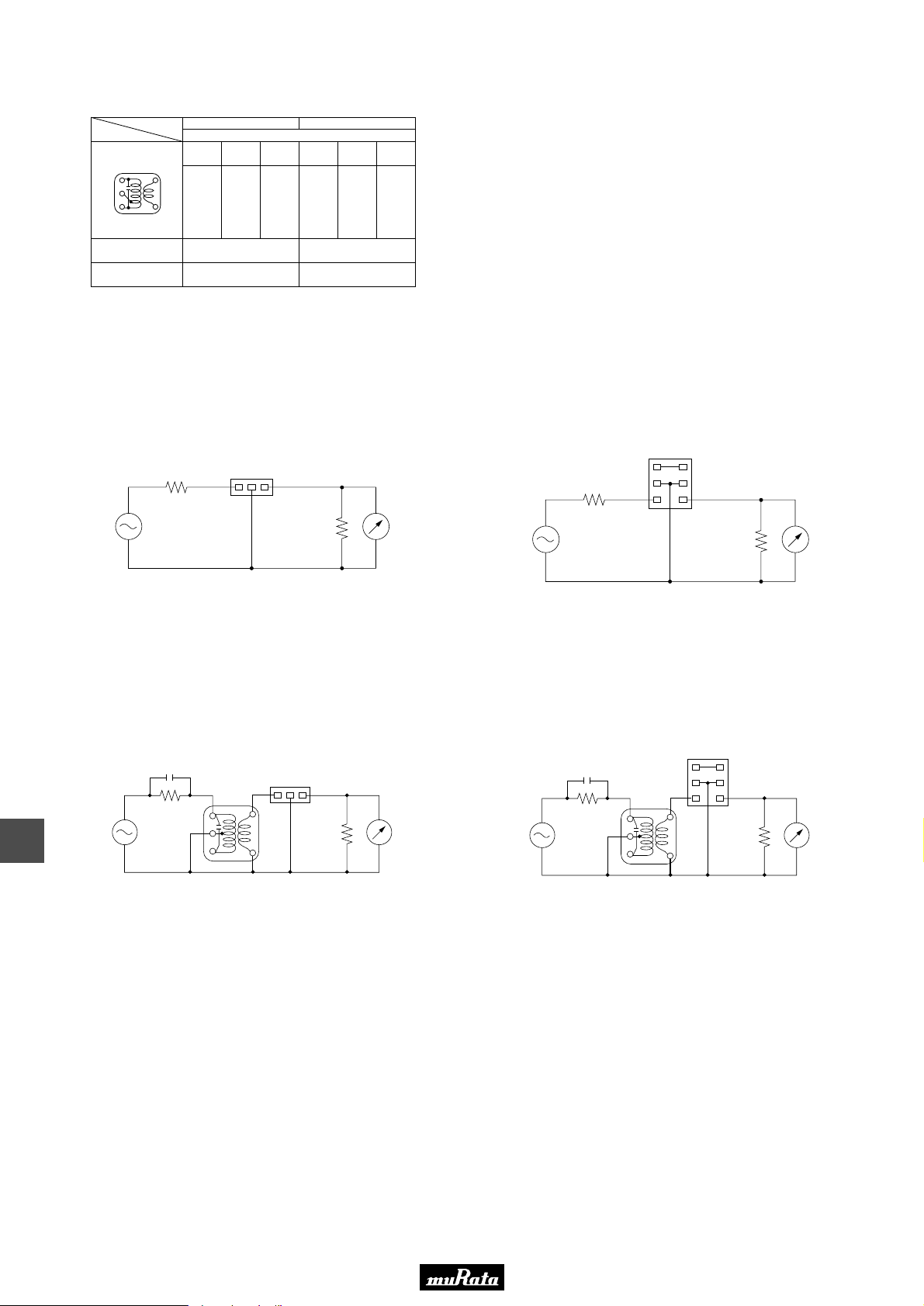
• This PDF catalog is downloaded from the website of Murata Manufacturing co., ltd. Therefore, it’s specifications are subject to change or our products in it may be discontinued without advance notice. Please check with our
!Note
• This PDF catalog has only typical specifications because there is no space for detailed specifications. Therefore, please approve our product specifications or transact the approval sheet for product specifications before ordering.
• Please read rating and !CAUTION (for storage, operating, rating, soldering, mounting and handling) in this catalog to prevent smoking and/or burning, etc.
!Note
sales representatives or product engineers before ordering.
• This catalog has only typical specifications because there is no space for detailed specifications. Therefore, please approve our product specifications or transact the approval sheet for product specifications before ordering.
■ Recommended IFT
P50E.pdf
10.2.9
Item
Winding Specification
S(3) (4)S
(2)
(1)
(Bottom view)
Tuning Capacitance
• Matching of CERAFILr SFULA/SFZLA series with IFT is decided by the IFT secondary side
impedance, |Z2|. The design target values of |Z2| are:
For SFULApB : 300Ω
For SFZLApA : 1kΩ
Type
(6)
No load Qu
SFULApB
(1)—(2) (2)—(3) (4)—(6)
70T 115T 7T
180pF
7×7mm IFT
105
SFZLApA
(1)—(2) (2)—(3) (4)—(6)
68T 84T 14T
90
180pF
■ Test Circuit (CERAFILr Only)
SFULA Series
S.S.G.
(Rg=50Ω)
3kΩ
(1) (3)
(2)
3kΩ
RF
Voltmeter
S.S.G.
(Rg=50Ω)
3kΩ
SFZLA Series
(3)
(2)
(1)
(4)
(5)
(6)
RF
3kΩ
Voltmeter
13
■ Test Circuit (CERAFILr with IFT)
SFULA Series
7pF
(1)
IFT
(3)
(2)
(1)
(2)
(4)
(6)
S.S.G.
(Rg=50Ω)
300kΩ
SFZLA Series
7pF
(3)
300kΩ
RF
3kΩ
Voltmeter
S.S.G.
(Rg=50Ω)
(3) (4)
(2)
(1)
(3)
(2)
IFT
(1)
(6)
(4)
(5)
(6)
RF
3kΩ
Voltmeter
46
Page 49
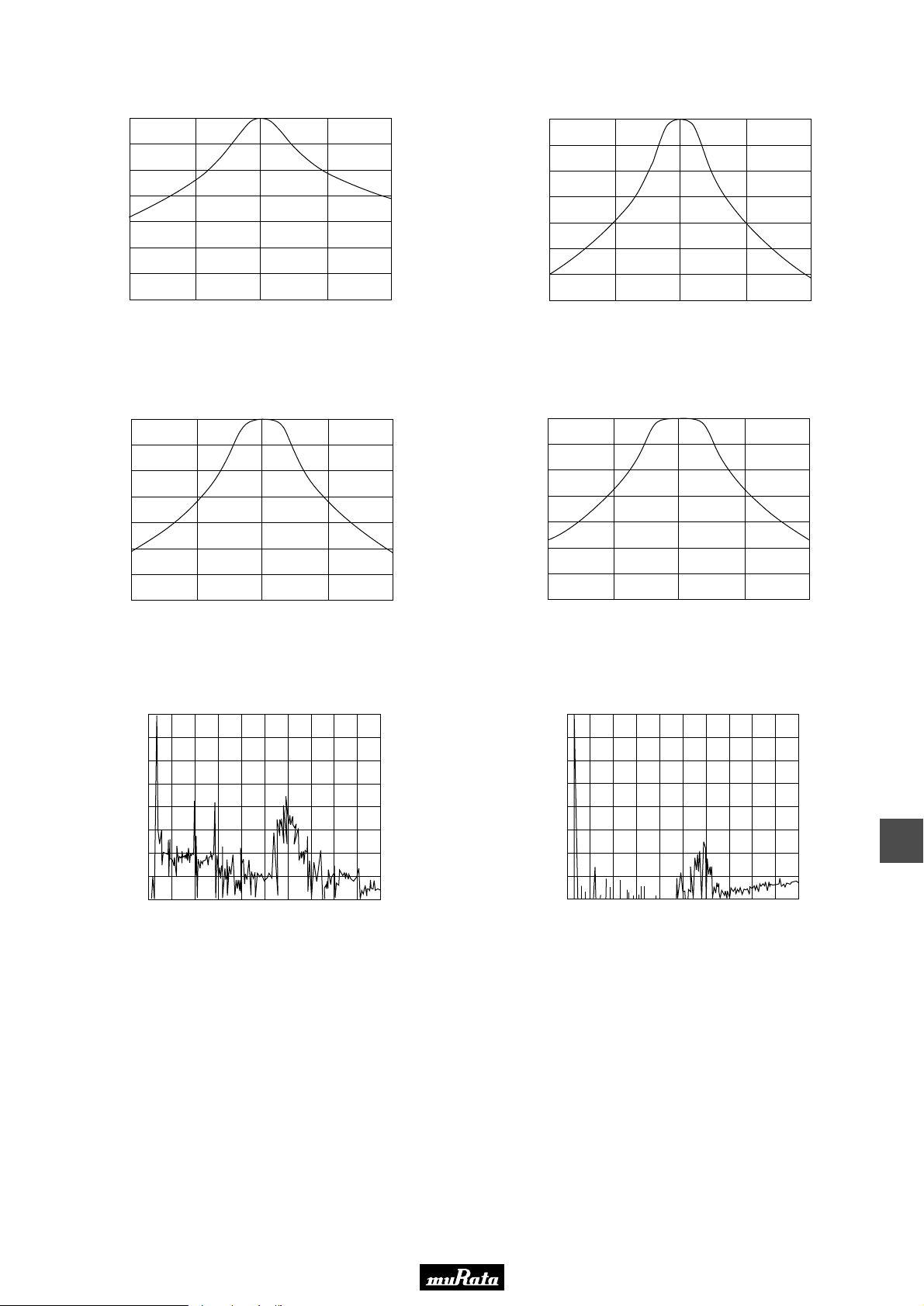
• This PDF catalog is downloaded from the website of Murata Manufacturing co., ltd. Therefore, it’s specifications are subject to change or our products in it may be discontinued without advance notice. Please check with our
!Note
• This PDF catalog has only typical specifications because there is no space for detailed specifications. Therefore, please approve our product specifications or transact the approval sheet for product specifications before ordering.
• Please read rating and !CAUTION (for storage, operating, rating, soldering, mounting and handling) in this catalog to prevent smoking and/or burning, etc.
!Note
sales representatives or product engineers before ordering.
• This catalog has only typical specifications because there is no space for detailed specifications. Therefore, please approve our product specifications or transact the approval sheet for product specifications before ordering.
■ Frequency Characteristics
0
IFT+SFULA455KU2B-B0
10
20
30
40
Attenuation (dB)
50
60
70
435 445 455 465 475
Frequency (kHz)
0
10
20
30
40
Attenuation (dB)
50
60
70
435 445 455 465 475
IFT+SFZLA455KN2A-B0
Frequency (kHz)
P50E.pdf
10.2.9
IFT+SFZLA455KS2A-B0
0
10
20
30
40
Attenuation (dB)
50
60
70
435 445 455 465 475
Frequency (kHz)
■ Frequency Characteristics (Spurious)
IFT+SFULA455KU2B-B0
0
10
20
30
40
50
Attennation (dB)
60
70
80
0 1 2 3 4 5 6 7 8 9 10
Frequency (MHz)
IFT+SFZLA455KT2A-B0
0
10
20
30
40
Attenuation (dB)
50
60
70
435 445 455 465 475
Frequency (kHz)
IFT+SFZLA Series
0
10
20
30
40
50
Attennation (dB)
60
70
80
0 1 2 3 4 5 6 7 8 9 10
Frequency (MHz)
13
47
Page 50
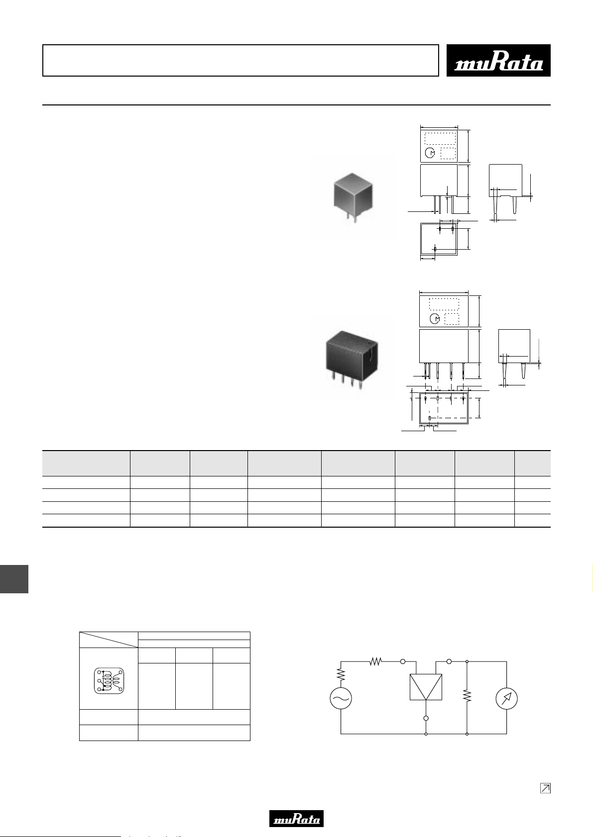
• This PDF catalog is downloaded from the website of Murata Manufacturing co., ltd. Therefore, it’s specifications are subject to change or our products in it may be discontinued without advance notice. Please check with our
!Note
• This PDF catalog has only typical specifications because there is no space for detailed specifications. Therefore, please approve our product specifications or transact the approval sheet for product specifications before ordering.
• Please read rating and !CAUTION (for storage, operating, rating, soldering, mounting and handling) in this catalog to prevent smoking and/or burning, etc.
!Note
sales representatives or product engineers before ordering.
• This catalog has only typical specifications because there is no space for detailed specifications. Therefore, please approve our product specifications or transact the approval sheet for product specifications before ordering.
CERAFILr (Filters/Traps/Discriminators) for Audio/Visual Equipment
CERAFILr 455kHz SFPLA/CFWLA Series
8.0±0.3
0.15±0.05
3.3±0.5
MARKING
EIAJ
CODE
2.7±0.3
(3)
11.0±0.5
MARKING
1.5 max.
(1)(2)
EIAJ
CODE
7.0±0.3
7.3±0.3
0.3
±
3.0
1.2±0.5
4.2±0.3
7.0±0.5
SFPLA/CFWLA series for AM use is one of the most
suitable intermediate filters, having such
distinctive features as high selectivity, high
stability, high attenuation, and adjustment-free
operation. Additionally its easy matching with IC
helps create an easy circuit design.
This is the most suitable for car-stereo and
all band radio with high attenuation.
SFPLA Series
0.8±0.1
0.6±0.1
Connection
(1) : Input
(2) : Ground
(3) : Output
P50E.pdf
10.2.9
0.3±0.1
(in mm)
14
4.3±0.3
0.8±0.1
0.6±0.1
Connection
(1) : Input
(2)(3)(4) : Ground
(5) : Output
(in mm)
Part Number
Center
Frequency (fo)
(kHz)
6dB
Bandwidth
(kHz)
Selectivity (-)
(dB)
CFWLA Series
Selectivity (+)
(dB)
0.15
2.9±0.3
1.35±0.5
2.3±0.5
Insertion
Loss
(4)
(5)
(dB)
(3)
2.9±0.3
2.92.9——0.30.3
2.0±0.3
7.5±0.5
3.5±0.5
2.6±0.3
1.2±0.5
(1)(2)
Input/Output
Impedance
(ohm)
SFPLA450KJ1A-B0 450.0 ±1.0kHz fn±2.0 min. 40 min.[fn-7.5kHz] 40 min.[fn+7.5kHz] 6.0 max. 2000 4
SFPLA450KH1A-B0 450.0 ±1.0kHz fn±3.0 min. 40 min.[fn-9kHz] 40 min.[fn+9kHz] 6.0 max. 2000 4
CFWLA450KJFA-B0 450.0 (fn) fn±2.0 min. 50 min.[fn-7.5kHz] 50 min.[fn+7.5kHz] 7.0 max. 2000 6
CFWLA450KHFA-B0 450.0 (fn) fn±3.0 min. 50 min.[fn-9kHz] 50 min.[fn+9kHz] 6.0 max. 2000 6
Area of Insertion Loss: at minimum loss point
Center frequency (fo) is defined by the center of 6dB bandwidth.
(fn) means nominal center frequency (450kHz).
For safety purposes, connect the output of filters to the IF amplifier through a D.C. blocking capacitor. Avoid applying a direct current to the output of ceramic filters.
The order quantity should be an integral multiple of the "Minimum Quantity" shown in the package page.
■ Recommended IFT
Item
Winding Specification
S(3) (4)S
(2)
(1)
(Bottom view)
Tuning Capacitance
• Matching of CERAFILr SFPLA/CFULA/CFWLA series with IFT is decided
by the Qu of IFT and IFT secondary side impedance, |Z2|. Set the Qu at
about 40 because a Qu value which is too high (e.g.,90) may produce
ripple in the waveform. It is recommended to match the impedance of |Z2|
with that of the CERAFILr.
Type
(6)
No load Qu
SFPLA/CFULA/CFWLA
7×7mm IFT
(1)—(2) (2)—(3) (4)—(6)
60T 125T 28T
40
180pF
■ Test Circuit
Rg
SSG
Input Output
R1
Ground
Rg+R1 =R2 : Input/Output Impedance
R2
1.5 max.
Element
RF
Voltmeter
48
Continued on the following page.
Page 51
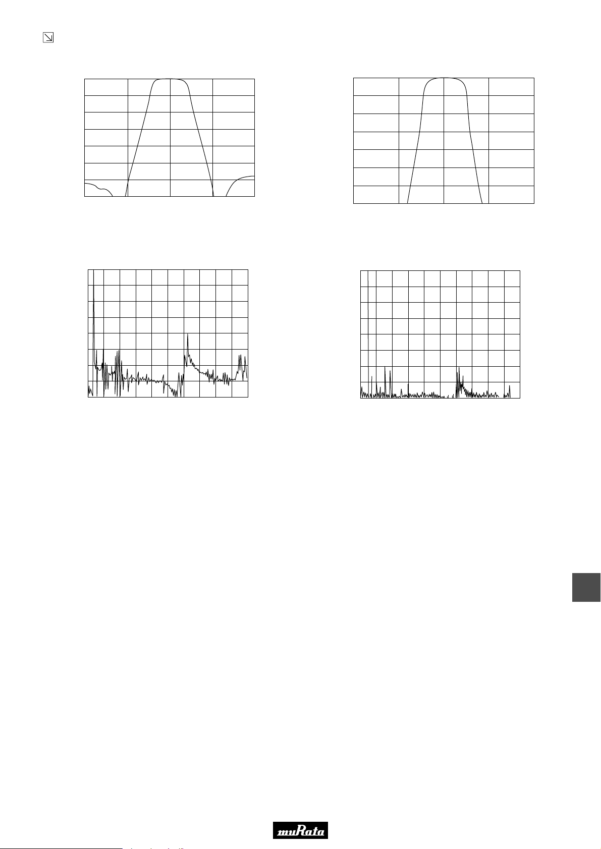
• This PDF catalog is downloaded from the website of Murata Manufacturing co., ltd. Therefore, it’s specifications are subject to change or our products in it may be discontinued without advance notice. Please check with our
!Note
• This PDF catalog has only typical specifications because there is no space for detailed specifications. Therefore, please approve our product specifications or transact the approval sheet for product specifications before ordering.
• Please read rating and !CAUTION (for storage, operating, rating, soldering, mounting and handling) in this catalog to prevent smoking and/or burning, etc.
!Note
sales representatives or product engineers before ordering.
• This catalog has only typical specifications because there is no space for detailed specifications. Therefore, please approve our product specifications or transact the approval sheet for product specifications before ordering.
Continued from the preceding page.
■ Frequency Characteristics
IFT+SFPLA450KH1A-B0
0
10
20
30
40
Attenuation (dB)
50
60
70
430 440 450 460 470
Frequency (kHz)
0
10
20
30
40
Attennation (dB)
50
60
70
430 440 450 460 470
IFT+CFWLA450KHFA-B0
Frequency (kHz)
■ Frequency Characteristics (Spurious)
0
IFT+SFPLA450KH1A-B0
10
20
30
40
Attennation (dB)
50
60
70
80
0 1 2 3 4 5 6 7 8 9 10
Frequency (kHz)
0
10
20
30
40
Attennation (dB)
50
60
70
80
0 1 2 3 4 5 6 7 8 9 10
IFT+CFWLA450KHFA-B0
Frequency (kHz)
P50E.pdf
10.2.9
49
14
Page 52
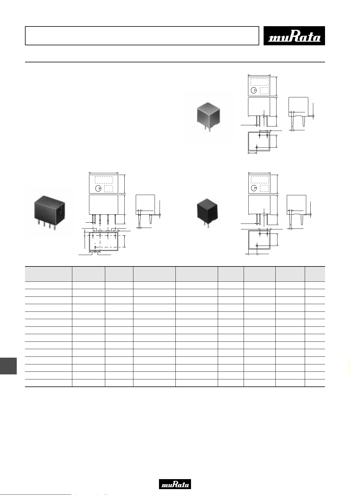
• This PDF catalog is downloaded from the website of Murata Manufacturing co., ltd. Therefore, it’s specifications are subject to change or our products in it may be discontinued without advance notice. Please check with our
!Note
• This PDF catalog has only typical specifications because there is no space for detailed specifications. Therefore, please approve our product specifications or transact the approval sheet for product specifications before ordering.
• Please read rating and !CAUTION (for storage, operating, rating, soldering, mounting and handling) in this catalog to prevent smoking and/or burning, etc.
!Note
sales representatives or product engineers before ordering.
• This catalog has only typical specifications because there is no space for detailed specifications. Therefore, please approve our product specifications or transact the approval sheet for product specifications before ordering.
CERAFILr (Filters/Traps/Discriminators) for Audio/Visual Equipment
CERAFILr 455kHz for AM Stereo Wide Bandwidth Type SFPLA/CFWLA/CFULA Series
8.0±0.3
0.15±0.05
3.3±0.5
MARKING
EIAJ
CODE
2.7±0.3
(3)
7.0±0.3
7.3±0.3
0.3
±
3.0
1.5 max.
1.2±0.5
(1)(2)
4.2±0.3
SFPLA/CFULA/CFWLA series for AM use is one of the most
suitable intermediate filters, having such
distinctive features as high selectivity, high
stability, high attenuation, and adjustment-free
operation. Additionally its easy matching with IC
helps create an easy circuit design.
Especially, CFULA/CFWLA_Y series is the frequency
fidelity in the high sound area of an AM stereo will
be improved with wide band, flat group delay time
characteristics.
SFPLA Series
0.8±0.1
0.6±0.1
Connection
(1) : Input
(2) : Ground
(3) : Output
P50E.pdf
10.2.9
0.3±0.1
(in mm)
15
CFWLA Series
Part Number
11.0±0.5
MARKING
0.15
2.9±0.3
(4)
(3)
(5)
1.35±0.5
2.3±0.5
Center
Frequency (fo)
(kHz)
EIAJ
CODE
2.9±0.3
2.92.9——0.30.3
2.0±0.3
7.0±0.5
7.5±0.5
3.5±0.5
2.6±0.3
1.2±0.5
(1)(2)
6dB
Bandwidth
(kHz)
4.3±0.3
0.8±0.1
1.5 max.
0.6±0.1
Connection
(1) : Input
(2)(3)(4) : Ground
(5) : Output
(in mm)
Selectivity (-)
(dB)
CFULA Series
Selectivity (+)
(dB)
Insertion
Loss
(dB)
8.0±0.3
MARKING
0.15±0.05
2.7±0.3
(3)
GDT 20µsec.
Bandwidth
(kHz)
EIAJ
CODE
1.5 max.
(1)(2)
3.3±0.5
7.0±0.3
7.3±0.3
3.0±0.3
1.2±0.5
4.2±0.3
Input/Output
Impedance
(ohm)
0.8±0.1
0.6±0.1
Connection
(1) : Input
(2) : Ground
(3) : Output
(in mm)
0.3±0.1
Element
SFPLA450KG1A-B0 450.0 ±1.0kHz fn±4.5 min. 30 min.[fn-9kHz] 30 min.[fn+9kHz] 6.0 max. - 2000 4
SFPLA450KF1A-B0 450.0 ±1.0kHz fn±6.0 min. 40 min.[fn-12.5kHz] 40 min.[fn+12.5kHz] 6.0 max. - 2000 4
SFPLA450KE1A-B0 450.0 ±1.0kHz fn±7.5 min. 40 min.[fn-15kHz] 40 min.[fn+15kHz] 6.0 max. - 1500 4
SFPLA450KD1A-B0 450.0 ±1.0kHz fn±10.0 min. 40 min.[fn-20kHz] 40 min.[fn+20kHz] 4.0 max. - 1500 4
CFULA450KG1Y-B0 450.0 ±1.0kHz fn±4.5 min. 40 min.[fn-15kHz] 40 min.[fn+15kHz] 10.0 max. fn±3 2000 4
CFULA450KF1Y-B0 450.0 ±1.0kHz fn±6.0 min. 40 min.[fn-17.5kHz] 40 min.[fn+17.5kHz] 9.0 max. fn±4 2000 4
CFULA450KD1Y-B0 450.0 ±1.0kHz fn±10.0 min. 40 min.[fn-25kHz] 40 min.[fn+25kHz] 7.0 max. fn±7 1500 4
CFWLA450KG1Y-B0 450.0 ±1.0kHz fn±4.5 min. 50 min.[fn-15kHz] 50 min.[fn+15kHz] 11.0 max. fn±4 2000 6
CFWLA450KF1Y-B0 450.0 ±1.0kHz fn±6.0 min. 50 min.[fn-17.5kHz] 50 min.[fn+17.5kHz] 10.0 max. fn±5 2000 6
CFWLA450KD1Y-B0 450.0 ±1.0kHz fn±10.0 min. 50 min.[fn-25kHz] 50 min.[fn+25kHz] 8.0 max. fn±8 1500 6
CFWLA450KGFA-B0 450.0 (fn) fn±4.5 min. 50 min.[fn-10kHz] 50 min.[fn+10kHz] 6.0 max. - 2000 6
CFWLA450KFFA-B0 450.0 (fn) fn±6.0 min. 50 min.[fn-12.5kHz] 50 min.[fn+12.5kHz] 6.0 max. - 2000 6
CFWLA450KEFA-B0 450.0 (fn) fn±7.5 min. 50 min.[fn-15kHz] 50 min.[fn+15kHz] 6.0 max. - 1500 6
CFWLA450KDFA-B0 450.0 (fn) fn±10.0 min. 50 min.[fn-20kHz] 50 min.[fn+20kHz] 4.0 max. - 1500 6
Area of Insertion Loss: at minimum loss point
Center frequency (fo) is defined by the center of 6dB bandwidth.
(fn) means nominal center frequency (450kHz).
For safety purposes, connect the output of filters to the IF amplifier through a D.C. blocking capacitor. Avoid applying a direct current to the output of ceramic filters.
The order quantity should be an integral multiple of the "Minimum Quantity" shown in the package page.
50
Page 53
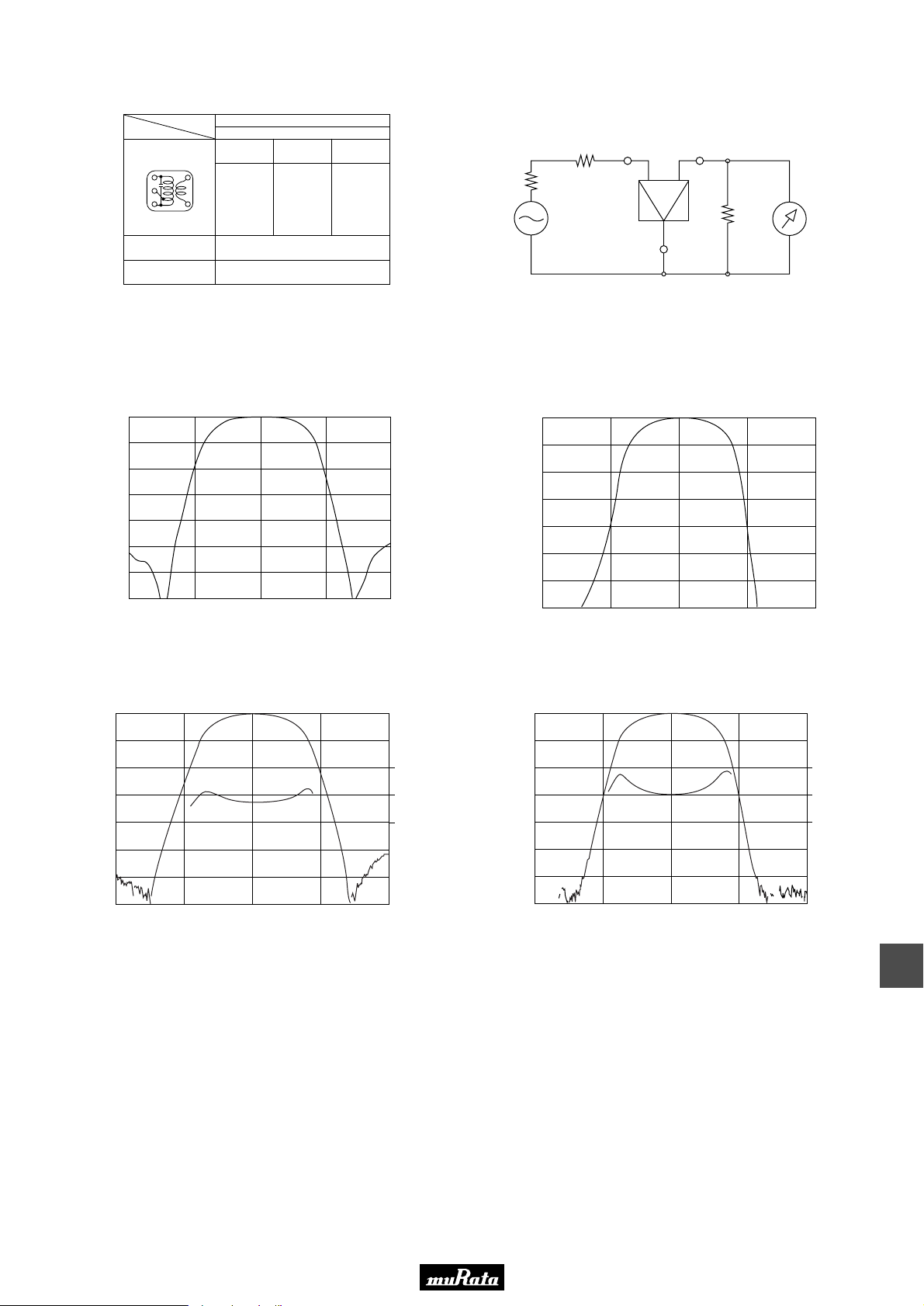
• This PDF catalog is downloaded from the website of Murata Manufacturing co., ltd. Therefore, it’s specifications are subject to change or our products in it may be discontinued without advance notice. Please check with our
!Note
• This PDF catalog has only typical specifications because there is no space for detailed specifications. Therefore, please approve our product specifications or transact the approval sheet for product specifications before ordering.
• Please read rating and !CAUTION (for storage, operating, rating, soldering, mounting and handling) in this catalog to prevent smoking and/or burning, etc.
!Note
sales representatives or product engineers before ordering.
• This catalog has only typical specifications because there is no space for detailed specifications. Therefore, please approve our product specifications or transact the approval sheet for product specifications before ordering.
P50E.pdf
10.2.9
■ Recommended IFT
No load Qu
Type
(1)—(2) (2)—(3) (4)—(6)
60T 125T 28T
(6)
Item
Winding Specification
S(3) (4)S
(2)
(1)
(Bottom view)
Tuning Capacitance
• Matching of CERAFILr SFPLA/CFULA/CFWLA series with IFT is decided
by the Qu of IFT and IFT secondary side impedance, |Z2|. Set the Qu at
about 40 because a Qu value which is too high (e.g.,90) may produce
ripple in the waveform. It is recommended to match the impedance of |Z2|
with that of the CERAFILr.
■ Frequency Characteristics
0
10
20
30
40
Attenuation (dB)
50
60
70
430 440 450 460 470
IFT+SFPLA450KF1A-B0
Frequency (kHz)
SFPLA/CFULA/CFWLA
7×7mm IFT
40
180pF
■ Test Circuit
Rg
SSG
0
10
20
30
40
Attennation (dB)
50
60
70
430
Input Output
R1
Ground
Rg+R1 =R2 : Input/Output Impedance
IFT+CFWLA450KFFA-B0
440
450 460 470
Frequency (kHz)
R2
RF
Voltmeter
0
10
20
30
40
Attennation (dB)
50
60
70
430
440
450 460 470
Frequency (kHz)
200
100
0
Group Delay Time (µsec.)
0
10
20
30
40
Attennation (dB)
50
60
70
430
IFT+CFULA450KF1Y-B0
IFT+CFWLA450KF1Y-B0
440
450 460 470
Frequency (kHz)
200
100
0
Group Delay Time (µsec.)
15
51
Page 54
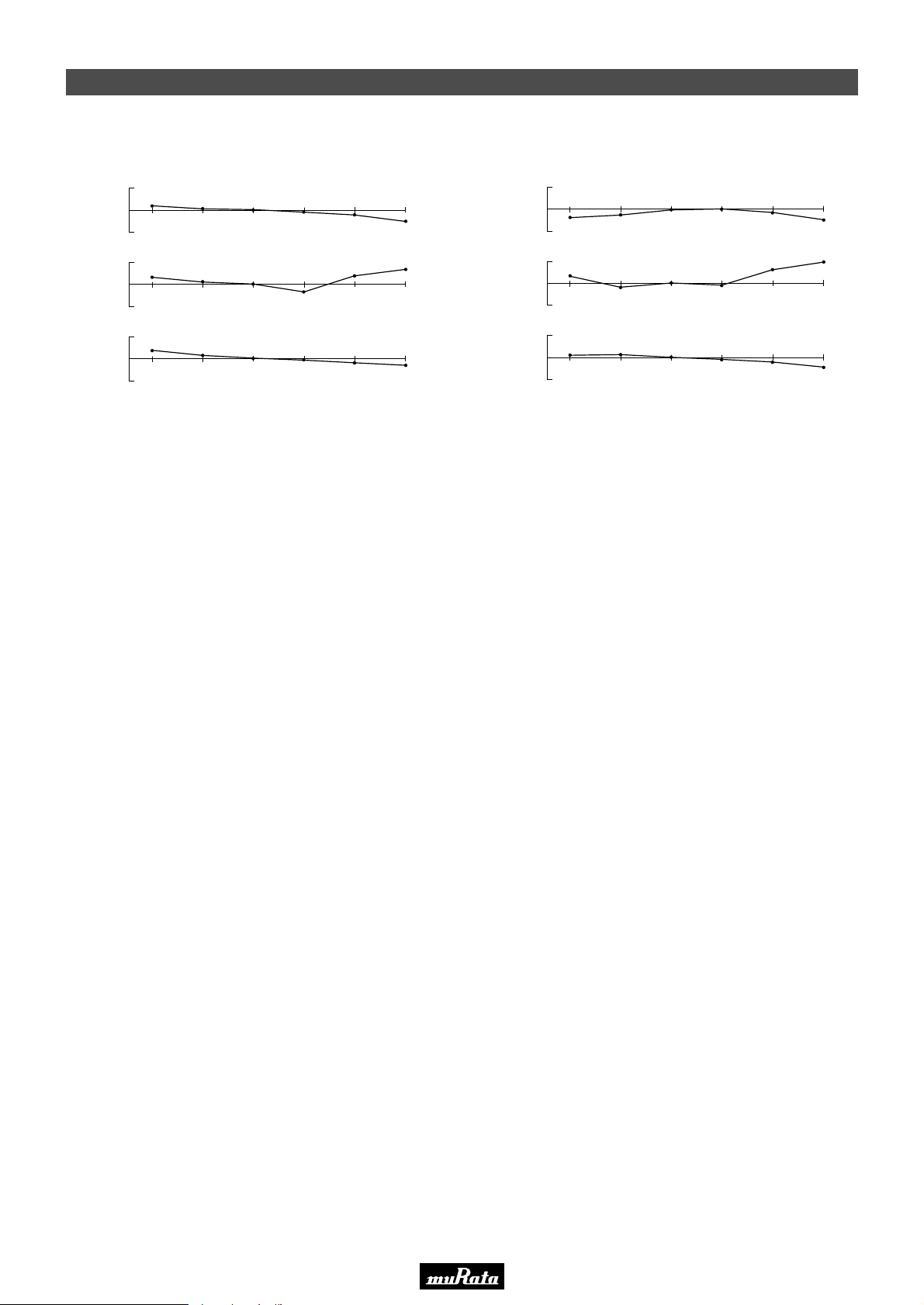
• This PDF catalog is downloaded from the website of Murata Manufacturing co., ltd. Therefore, it’s specifications are subject to change or our products in it may be discontinued without advance notice. Please check with our
!Note
• This PDF catalog has only typical specifications because there is no space for detailed specifications. Therefore, please approve our product specifications or transact the approval sheet for product specifications before ordering.
• Please read rating and !CAUTION (for storage, operating, rating, soldering, mounting and handling) in this catalog to prevent smoking and/or burning, etc.
!Note
sales representatives or product engineers before ordering.
• This catalog has only typical specifications because there is no space for detailed specifications. Therefore, please approve our product specifications or transact the approval sheet for product specifications before ordering.
CERAFILr 455kHz SFp Series Temperature Characteristics
P50E.pdf
10.2.9
■ SFZLA455KS2A-B0
+1
0
(kHz)
-
20
-
1
Center Frequency
+1
0
(dB)
-
Insertion Los
3dB Band Width
20
-
1
+1
0
-
20
(kHz)
-
1
0
0
0
■ SFPLA450KH1A-B0
Temperature (D)
20
20
20
40
40
40
60
60
Temperature (D)
Temperature (D)
60
80
80
80
+1
-
20
0
(kHz)
-
1
Center Frequency
+1
0
(dB)
-
20
Insertion Los
-
1
+1
0
-
20
(kHz)
3dB Band Width
-
1
0
0
0
20
20
20
40
40
40
Temperature (D)
60
60
Temperature (D)
Temperature (D)
60
80
80
80
15
52
Page 55
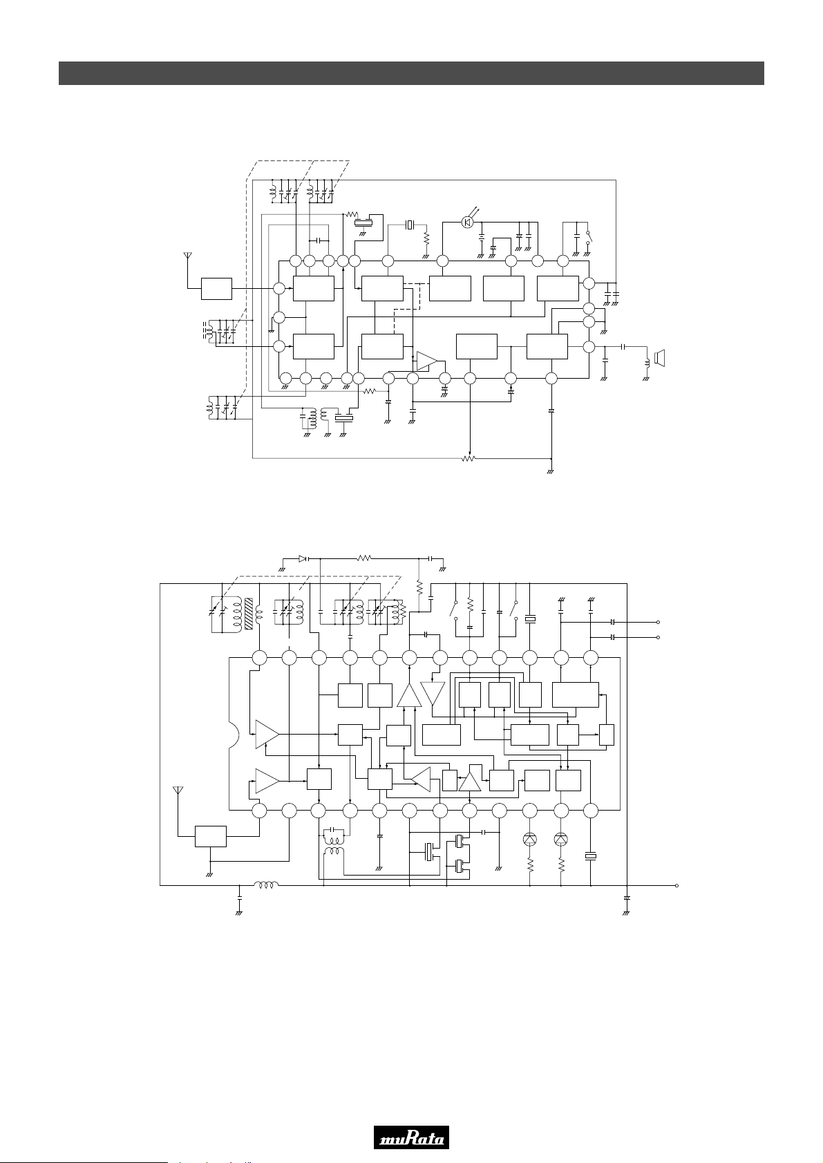
• This PDF catalog is downloaded from the website of Murata Manufacturing co., ltd. Therefore, it’s specifications are subject to change or our products in it may be discontinued without advance notice. Please check with our
!Note
• This PDF catalog has only typical specifications because there is no space for detailed specifications. Therefore, please approve our product specifications or transact the approval sheet for product specifications before ordering.
• Please read rating and !CAUTION (for storage, operating, rating, soldering, mounting and handling) in this catalog to prevent smoking and/or burning, etc.
!Note
sales representatives or product engineers before ordering.
• This catalog has only typical specifications because there is no space for detailed specifications. Therefore, please approve our product specifications or transact the approval sheet for product specifications before ordering.
CERAFILr 455kHz SFp Series Application Circuit
■ Portable Radio
SFULA455KU2B-B0
FM PF FM OSC
®
FM CERAFIL
(SFELF10M7FA00-B0)
P50E.pdf
10.2.9
FM
BPF
AM ANT
AM OSC
SFULA455KU2B-B0
L3
FM
PF
AM
PF
24 23 22 20 19 18 17 16 15 14 13
12
13
10
IS2236
L1 T1L2
20p
OUTINVcc1
IF
OUT
FM
FRONT
END
AM
FRONT
END
20 161811 5
®
AM CERAFIL
(SFULA455KU2B-B0)
100k
22p
5p
15p
FM
OSCAMOSC
21
FM IF
IN
FM IF
AMP
DETECTOR
AM IF
AMP
DETECTOR
AM IF
IN
8p
2
FM DISCRI
+
DEF
OUT
R
1917679 14
METER
TUNING
METER
CXA1019M (SONY)
AGC
AMP
DEP
+
OUT
0.022µ
100k
ST
330p
33k
10µ
MO AM
+
LPF1
MPX
IN
RIPPLE
FILTER
VOL
VOL
22k
+
-
0.1µ
LPF2 VCO
+
+
25 26 15
Vcc
AF
PRE/POWER
AMP
AF IN
+
CSBLA456
KE2ZF16-B0
FM
0.1µ
+
-
REGULATOR
3244212322
+
0.015µ
OUTLOUT
R
FM/AM
BAND SELECT
REG
OUT
8
28
1
27
4.7µ
0.015µ
+
+
4.7µ
+
SP
+
Unit
R
: Ω
C
: F
L
: H
-
-
L
R
BPF
0.022µ
FM
RF IN
AM
RF
FM
RF
10µ
FM
MIX
AM
MIX
FM
OSCAMOSC
AM
MIX
AM
MIX
2
T
AM
AGC
PRE
AF
AM/FM
AM
MONO SW
DET
33µ
AM
AGC
+
-
AM
L
IF
DET
654321 7 8 9 10 11 12
Vcc2GND1
SFULA455
KU2B-B0
AM
IF IN
FM
IF IN
SFELF10
M7FA00-B0
Phase
COM
FM
IF
GND2
0.033µ
Phase
COM
FM
DET
Freq
Divider
TUN
LED
VCO
TUN
LED
560
ST
DECODER
HYS SW
ST
LED
ST
QUAD
LED
CDALF10
M7GA16-B0
TA8122AN (TOSHIBA)
560
+
22µ
-
Vcc
(3V)
Unit
R
C
: Ω
: F
L
: H
15
53
Page 56
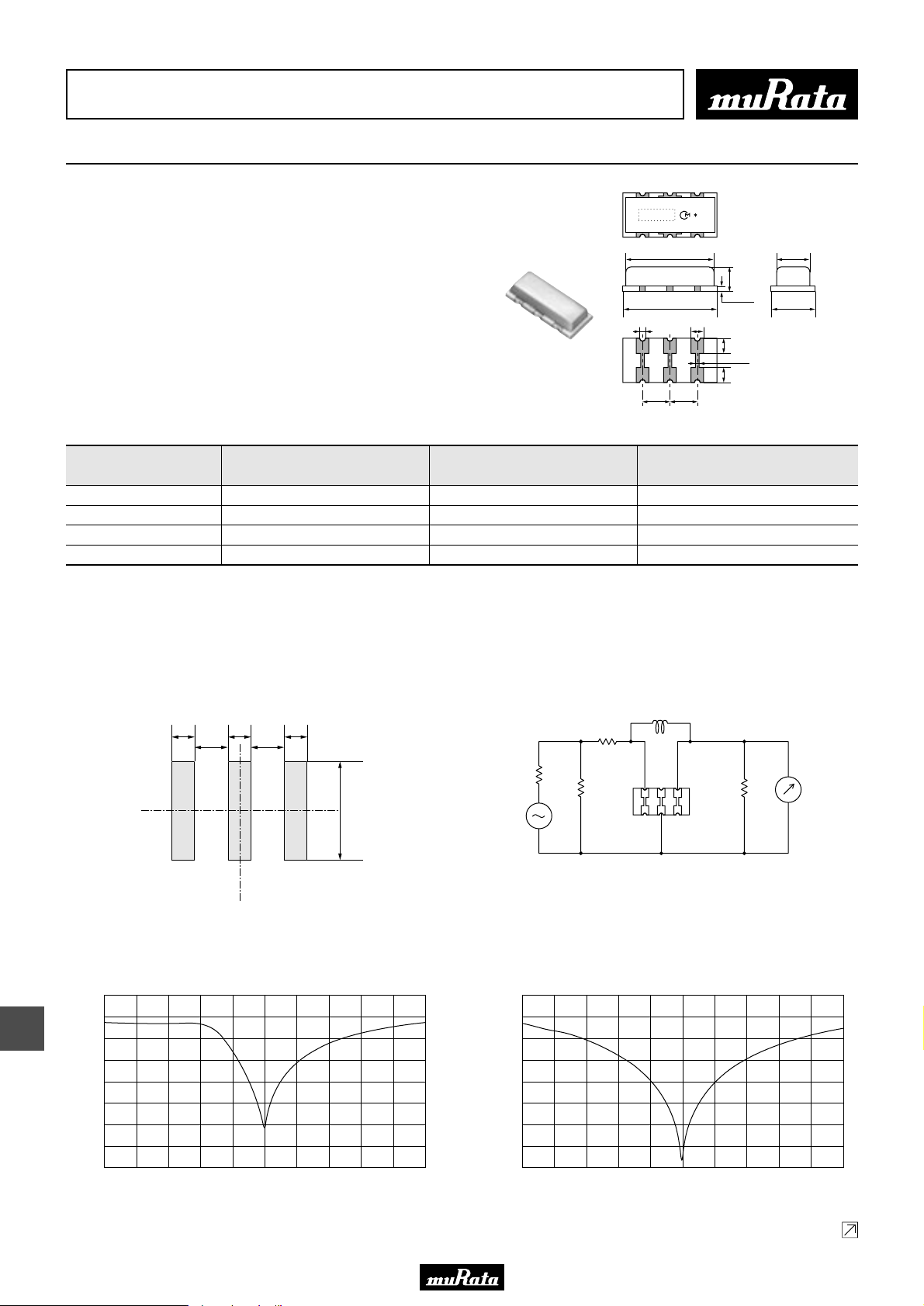
• This PDF catalog is downloaded from the website of Murata Manufacturing co., ltd. Therefore, it’s specifications are subject to change or our products in it may be discontinued without advance notice. Please check with our
!Note
• This PDF catalog has only typical specifications because there is no space for detailed specifications. Therefore, please approve our product specifications or transact the approval sheet for product specifications before ordering.
• Please read rating and !CAUTION (for storage, operating, rating, soldering, mounting and handling) in this catalog to prevent smoking and/or burning, etc.
!Note
sales representatives or product engineers before ordering.
• This catalog has only typical specifications because there is no space for detailed specifications. Therefore, please approve our product specifications or transact the approval sheet for product specifications before ordering.
CERAFILr (Filters/Traps/Discriminators) for Audio/Visual Equipment
Ceramic Trap 4.5-6.5MHz Chip Type TPSKA Series
SMD ceramic trap TPSKA_B is small and thin SMD trap
sealed with a metal cap. Recommended for LCD-TVs, and
small and thin tuners.
■ Features
1. High attenuation and high performance group
delay time
2. Small and thin package
3. Reflow-solderable
7.9±0.2 3.0±0.1
1.8±0.2
8.5±0.2
0.6±0.2 1.0±0.1
(1) (2) (3)
2.5±0.2 2.5±0.2
0.5±0.1
1.3±0.2
0.3±0.1
1.3±0.2
3.8±0.2
(1) : Input
(2) : Ground
(3) : Output
P50E.pdf
10.2.9
(in mm)
Part Number
Nominal Center
Frequency (fn1)
(MHz)
Attenuation
(at fn1)
(dB)
30dB Attenuation
BW (fn1)
(kHz)
TPSKA4M50B00-R3 4.500 35 min. 50 min.
TPSKA5M50B00-R3 5.500 35 min. 70 min.
TPSKA6M00B00-R3 6.000 35 min. 70 min.
TPSKA6M50B00-R3 6.500 35 min. 70 min.
For safety purposes, connect the output of filters to the IF amplifier through a D.C. blocking capacitor. Avoid applying a direct current to the output of ceramic filters.
The order quantity should be an integral multiple of the "Minimum Quantity" shown in the package page.
■ Standard Land Pattern Dimensions
1.0 1.0
1.5 1.5
1.0
4.8
(in mm)
■ Test Circuit
Rg
S.S.G.
L
R1
50Ω R2
Rg=50Ω
R1=330Ω
R2=1.0kΩ
L=15µH
RF
Voltmeter
16
■ Frequency Characteristics
TPSKA4M50B00-R1
0
10
20
30
40
Attenuation (dB)
50
60
70
4.0 4.24.1 4.3 4.5 4.7 4.94.4 4.6 4.8 5.0
54
Frequency (MHz)
TPSKA5M50B00-R1
0
10
20
30
40
Attenuation (dB)
50
60
70
5.0 5.25.1 5.3 5.5 5.7 5.95.4 5.6 5.8 6.0
Frequency (MHz)
Continued on the following page.
Page 57
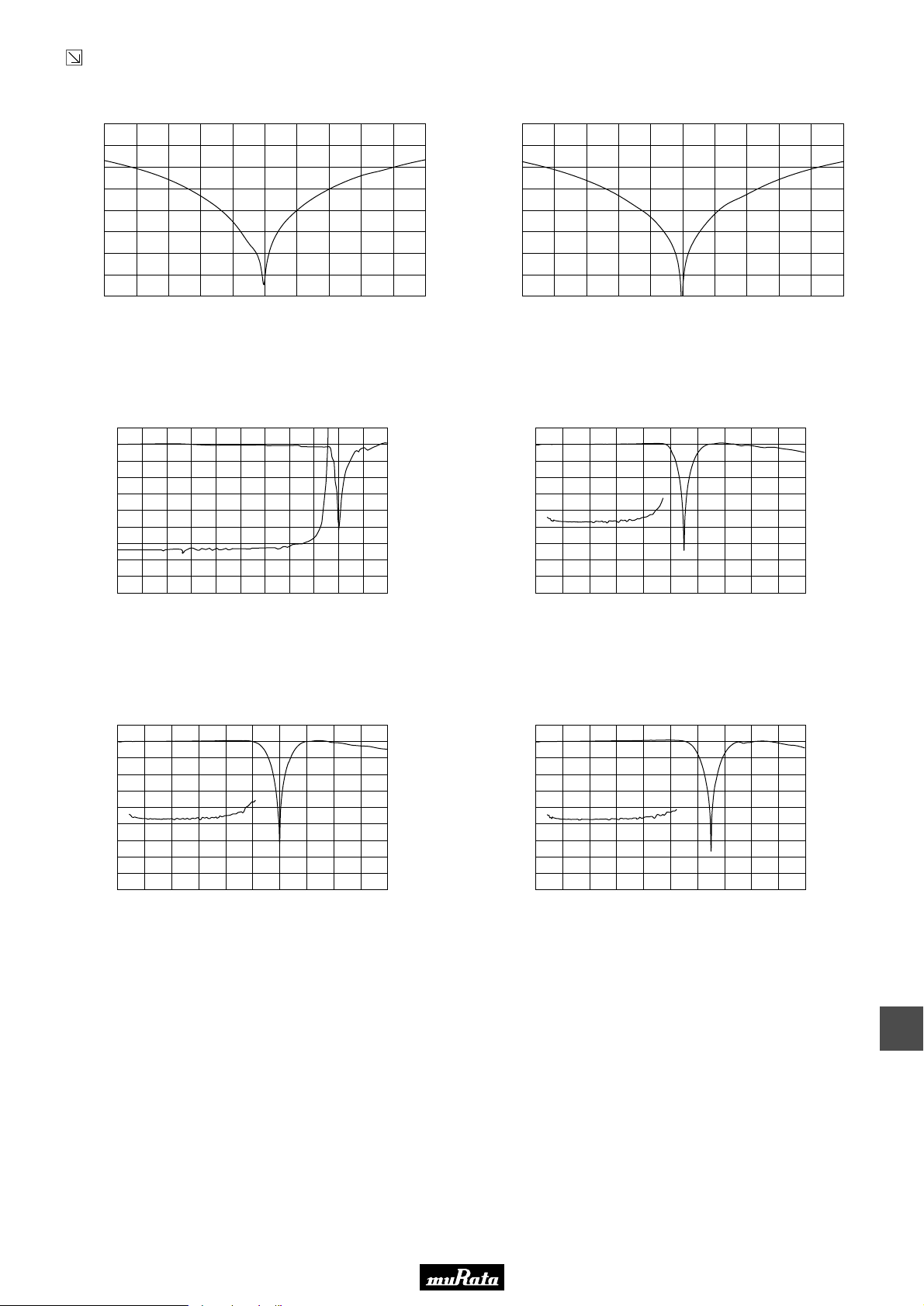
• This PDF catalog is downloaded from the website of Murata Manufacturing co., ltd. Therefore, it’s specifications are subject to change or our products in it may be discontinued without advance notice. Please check with our
!Note
• This PDF catalog has only typical specifications because there is no space for detailed specifications. Therefore, please approve our product specifications or transact the approval sheet for product specifications before ordering.
• Please read rating and !CAUTION (for storage, operating, rating, soldering, mounting and handling) in this catalog to prevent smoking and/or burning, etc.
!Note
sales representatives or product engineers before ordering.
• This catalog has only typical specifications because there is no space for detailed specifications. Therefore, please approve our product specifications or transact the approval sheet for product specifications before ordering.
Continued from the preceding page.
■ Frequency Characteristics
TPSKA6M00B00-R1
TPSKA6M50B00-R1
P50E.pdf
10.2.9
0
10
20
30
40
Attenuation (dB)
50
60
70
5.5 5.75.6 5.8 6.0 6.2 6.45.9 6.1 6.3 6.5
Frequency (MHz)
■ Frequency Characteristics (Spurious)
TPSKA4M50B00-R1
0
10
20
30
40
50
Attenuation (dB)
60
70
80
0 1.0 2.0 3.0 4.0 5.0
Frequency (MHz)
700
600
500
400
300
200
100
0
0
10
20
30
40
Attenuation (dB)
50
60
70
6.0 6.26.1 6.3 6.5 6.7 6.96.4 6.6 6.8 7.0
Frequency (MHz)
TPSKA5M50B00-R1
0
10
20
30
40
G.D.T. (nsec)
50
Attenuation (dB)
60
70
80
0 1.0 2.0 3.0 4.0 5.0 6.0 7.0 8.0 9.0 10.0
Frequency (MHz)
1000
800
600
400
200
0
G.D.T. (nsec.)
TPSKA6M00B00-R1
0
10
20
30
40
50
Attenuation (dB)
60
70
80
0 1.0 2.0 3.0 4.0 5.0 6.0 7.0 8.0 9.0 10.0
Frequency (MHz)
1000
800
600
400
200
0
TPSKA6M50B00-R1
0
10
20
30
40
G.D.T. (nsec.)
50
Attenuation (dB)
60
70
80
0 1.0 2.0 3.0 4.0 5.0 6.0 7.0 8.0 9.0 10.0
Frequency (MHz)
1000
800
600
400
200
0
G.D.T. (nsec.)
16
55
Page 58
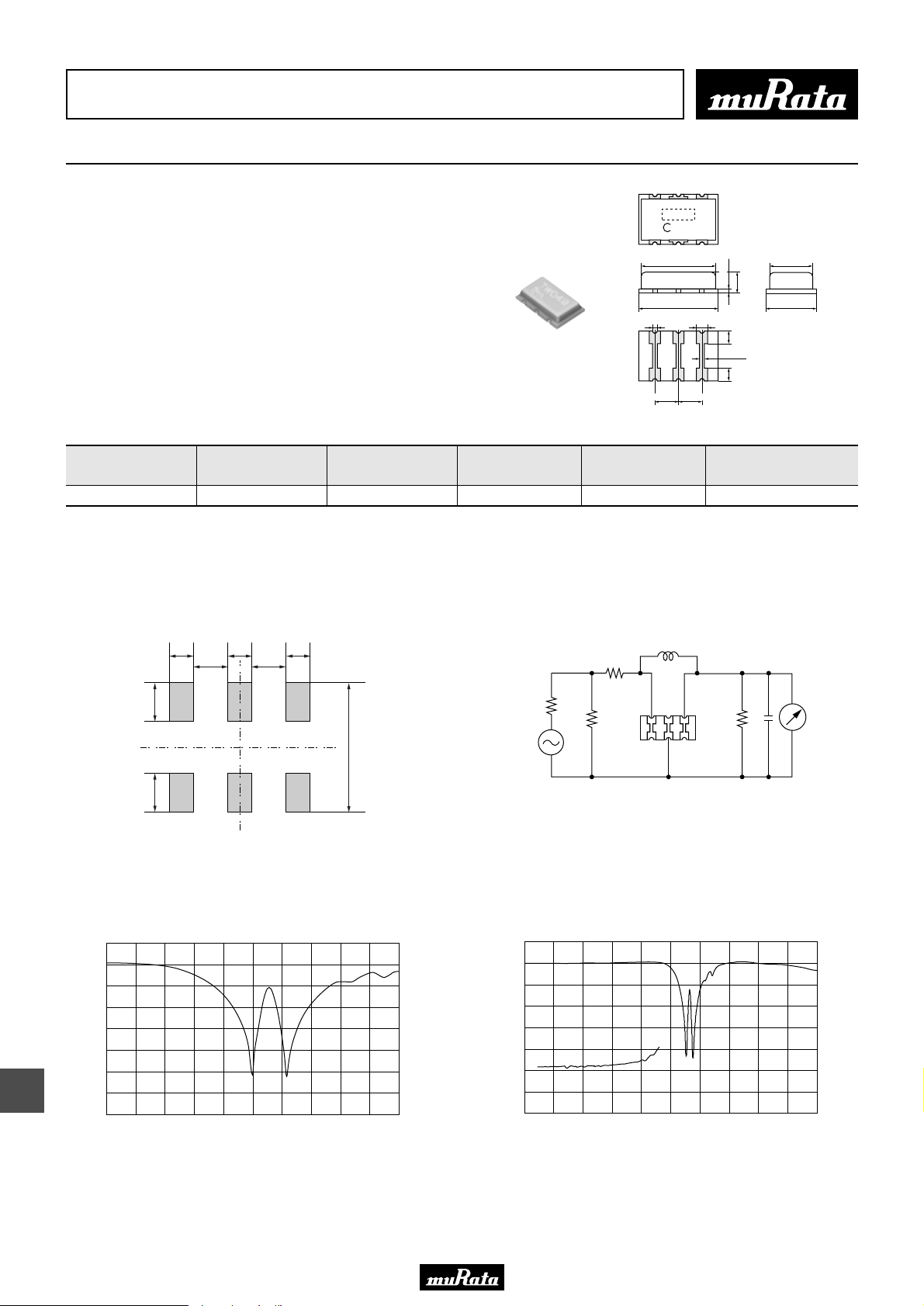
• This PDF catalog is downloaded from the website of Murata Manufacturing co., ltd. Therefore, it’s specifications are subject to change or our products in it may be discontinued without advance notice. Please check with our
!Note
• This PDF catalog has only typical specifications because there is no space for detailed specifications. Therefore, please approve our product specifications or transact the approval sheet for product specifications before ordering.
• Please read rating and !CAUTION (for storage, operating, rating, soldering, mounting and handling) in this catalog to prevent smoking and/or burning, etc.
!Note
sales representatives or product engineers before ordering.
• This catalog has only typical specifications because there is no space for detailed specifications. Therefore, please approve our product specifications or transact the approval sheet for product specifications before ordering.
CERAFILr (Filters/Traps/Discriminators) for Audio/Visual Equipment
Ceramic Trap 4.5-6.5MHz Chip Type Double Traps TPWKA Series
P50E.pdf
10.2.9
SMD ceramic trap TPWKA is small and thin SMD trap
M
∗
sealed with a metal cap. Recommended for LCD-TVs, and
small and thin tuners.
This series consists of 2 wafers with 2 trap
frequencies. Recommended for multi-standard set.
■ Features
1. Good performance of attenuation
2. Small and thin package
3. Reflow-solderable
Part Number
Nominal Center
Frequency (fn1)
(MHz)
TPWKA5M50B04-R1 5.500 5.742 30 min. 30 min. 50 min.
For safety purposes, connect the output of filters to the IF amplifier through a D.C. blocking capacitor. Avoid applying a direct current to the output of ceramic filters.
The order quantity should be an integral multiple of the "Minimum Quantity" shown in the package page.
■ Standard Land Pattern Dimensions
1.2
1.2 1.2
1.3 1.3
Nominal Center
Frequency (fn2)
(MHz)
Attenuation
(at fn1)
(dB)
■ Test Circuit
Attenuation
R1
7.9±0.2 4.2±0.1
8.5±0.2 5.0±0.2
0.4±0.2 1.0±0.1
(1) (2) (3)
2.5±0.2 2.5±0.2
(at fn2)
(dB)
L
0.4±0.1
1.5±0.2
1.3±0.2
(1) : Input or Output
0.3±0.1
(2) : Ground
(3) : Output or Input
1.3±0.2
30dB Attenuation
BW (fn1)
(kHz)
(in mm)
17
1.91.9
■ Frequency Characteristics
0
10
20
30
40
Attenuation (dB)
50
60
70
4.5 4.7 4.9 5.1 5.3 5.5 5.7 5.9 6.1 6.3 6.5
Frequency (MHz)
5.8
(in mm)
Rg
S.S.G.
50Ω
Rg = 50 Ω
R1 = 150 Ω
R2 = 330 Ω
C2 = 10pF (Including stray capacitance and input capacitance of RF voltmeter)
R2
L = 8.2 µH
■ Frequency Characteristics (Spurious)
0
10
20
30
40
Attenuation (dB)
50
60
70
0 1.0 2.0 3.0 4.0 5.0 6.0 7.0 8.0 9.0 10.0
Frequency (MHz)
C2
RF
Voltmeter
800
600
400
G.D.T. (nesc)
200
0
56
Page 59
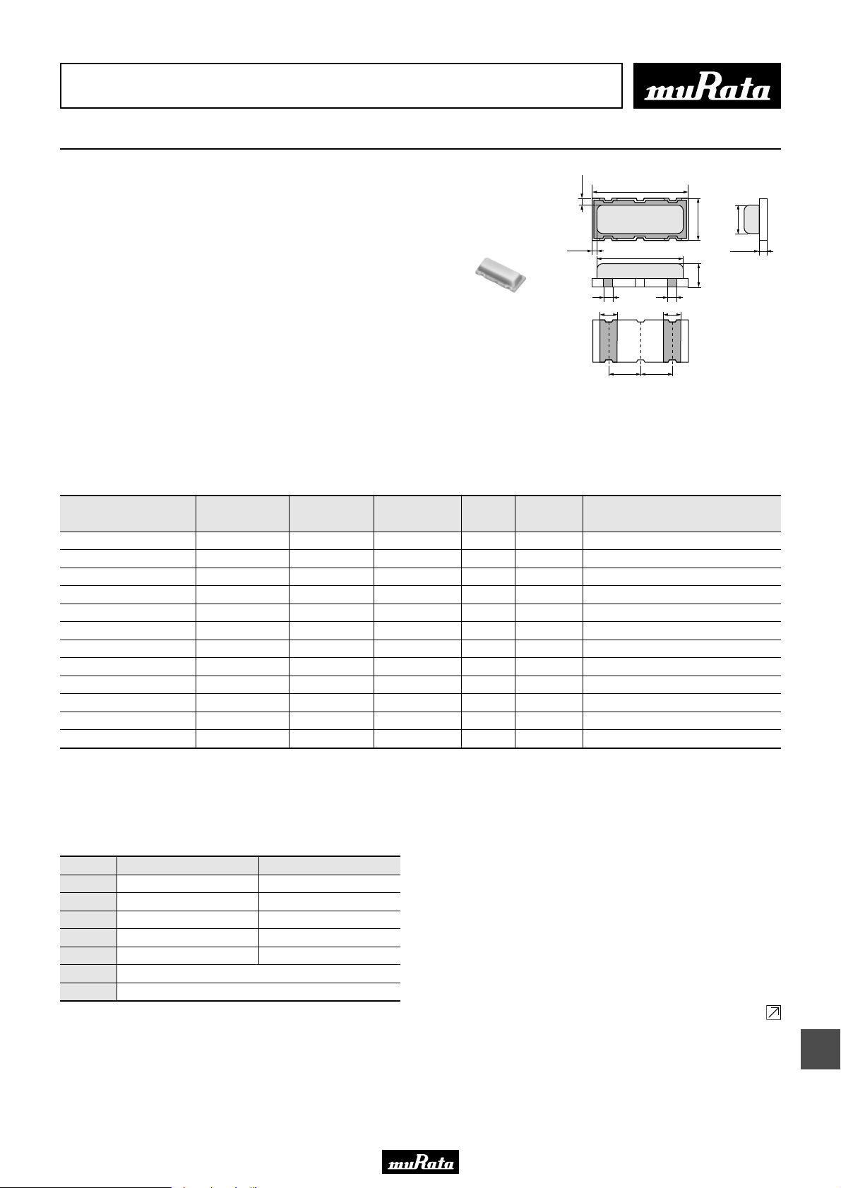
• This PDF catalog is downloaded from the website of Murata Manufacturing co., ltd. Therefore, it’s specifications are subject to change or our products in it may be discontinued without advance notice. Please check with our
!Note
• This PDF catalog has only typical specifications because there is no space for detailed specifications. Therefore, please approve our product specifications or transact the approval sheet for product specifications before ordering.
• Please read rating and !CAUTION (for storage, operating, rating, soldering, mounting and handling) in this catalog to prevent smoking and/or burning, etc.
!Note
sales representatives or product engineers before ordering.
• This catalog has only typical specifications because there is no space for detailed specifications. Therefore, please approve our product specifications or transact the approval sheet for product specifications before ordering.
CERAFILr (Filters/Traps/Discriminators) for Audio/Visual Equipment
Ceramic Discriminator 10.7MHz Ultra Thin Chip Type CDSCB Series
P50E.pdf
10.2.9
CDSCB10M7 series forms a resonator on a piezoelectric
0.3±0.2
4.5±0.1
ceramic substrate. In combination with ICs, this type
obtains stable demodulation characteristics in a wide
bandwidth.
0.2±0.2
4.1 max.
They have 1.0mm max. thickness and small mounting area
(4.5x2.0mm).
0.4(ref.) 0.4(ref.)
0.8±0.10.8±0.1
■ Features
1. Compact and high reliability and recommended for
automotive applications.
2. Can be combined with various ICs. The IC is
determined by the last number in the part number.
3. Stable demodulation characteristics can be
obtained without adjustment.
4. Stable temperature characteristics
5. Available lead (Pb) free solder reflow.
Part Number
CDSCB10M7GA105A-R0 10.700 ±30kHz 220 min. 110 min. 1.5 max. - TEA5757HL
CDSCB10M7GA113-R0 10.700 ±30kHz 300 min. 110 min. 1.0 max. - TA2154FN
CDSCB10M7GA119-R0 10.700 ±30kHz 500 min. 75 min. 1.0 max. - TRF6901
CDSCB10M7GA121-R0 10.700 ±30kHz 390 min. 80 min. 1.0 max. - LV23100V
CDSCB10M7GA135-R0 10.700 ±30kHz 155 min. 75 min. - - TH71101
CDSCB10M7GA136-R0 10.700 ±30kHz 140 min. 120 min. - - TH7122
CDSCB10M7GF072-R0 10.700 (fn) fn±150 min. 130 min. 2.0 max. - TA31161
CDSCB10M7GF107S-R0 10.700 (fn) fn±80 min. 52 min. 3.0 max. - TA31272FN
CDSCB10M7GF109-R0 10.700 (fn) fn±100 min. 170 min. 3.0 max. - TK14588V
CDSCB10M7GF123-R0 10.700 (fn) - - - 900 min. TA31275FN
CDSCB10M7GF123S-R0 10.700 (fn) - - - 900 min. TA31275FN
CDSCB10M7GF126-R0 10.700 (fn) - - - 400 min. NJM2295AV
(fn) means nominal center frequency (10.700MHz).
For safety purposes, avoid applying a direct current between the terminals.
The order quantity should be an integral multiple of the "Minimum Quantity" shown in the package page.
Center
Frequency (fo)
(MHz)
Recovered
Audio 3dB BW
(kHz)
Recovered
Audio Output
(mV)
Distortion
(%)
S Curve
(mV)
1.5±0.1
1.5±0.1
IC
2.0±0.1
1.4 max.
0.4±0.05
1.0 max.
(in mm)
■ Standard Center Frequency Rank Code
CODE
D
B
A
C
E
Z
M
30kHz Step
10.64MHz±30kHz
10.67MHz±30kHz
10.70MHz±30kHz
10.73MHz±30kHz
10.76MHz±30kHz
Combination A, B, C, D, E
Combination A, B, C
25kHz Step
10.650MHz±25kHz
10.675MHz±25kHz
10.700MHz±25kHz
10.725MHz±25kHz
10.750MHz±25kHz
Continued on the following page.
18
57
Page 60
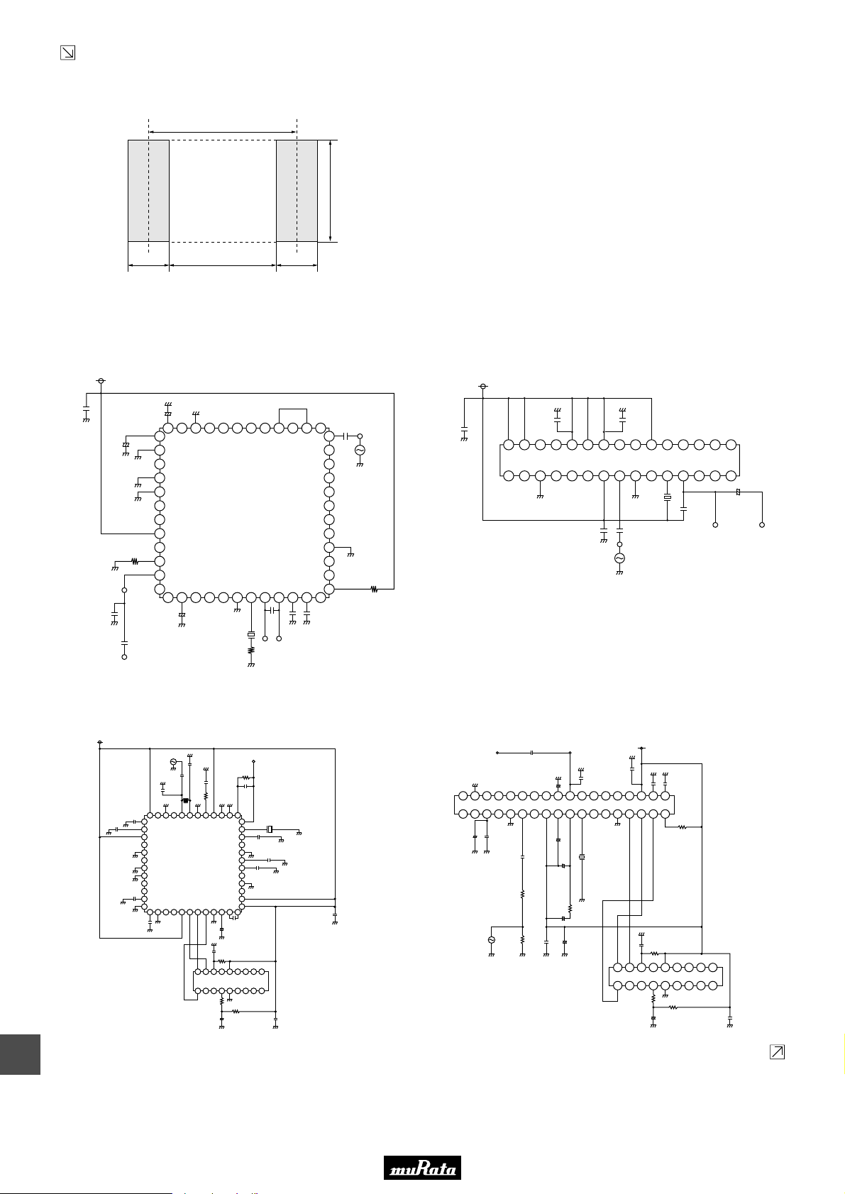
• This PDF catalog is downloaded from the website of Murata Manufacturing co., ltd. Therefore, it’s specifications are subject to change or our products in it may be discontinued without advance notice. Please check with our
!Note
• This PDF catalog has only typical specifications because there is no space for detailed specifications. Therefore, please approve our product specifications or transact the approval sheet for product specifications before ordering.
• Please read rating and !CAUTION (for storage, operating, rating, soldering, mounting and handling) in this catalog to prevent smoking and/or burning, etc.
!Note
sales representatives or product engineers before ordering.
• This catalog has only typical specifications because there is no space for detailed specifications. Therefore, please approve our product specifications or transact the approval sheet for product specifications before ordering.
Continued from the preceding page.
■ Standard Land Pattern Dimensions
3.0
2.6
1.0 2.0 1.0
(in mm)
■ Test Circuit
0.1µ
Vcc (3.0V)
100µ
DC OUT
330p
0.22µ
+
AF OUT
CDSCB10M7GA105A-R0
10µ
+
48 41424344454647
1
2
3
4
5
6
7
8
9
100k
10
11
12
13
+
4.7µ
TEA5757HL
(PHILIPS)
X
150
40213922382337
20191817161514
0.47µ
AFC (n)
AFC (p)
0.1µ
0.1µ
36
35
S.S.G.
34
33
32
31
30
29
28
27
26
25
24
10
0.1µ
X : CDSCB10M7GA105A-R0
Unit CR: F
Vcc (1.2V)
0.01µ
30 23242526272829
1 8765432
: Ω
CDSCB10M7GA113-R0
0.01µ
0.01µ
2292110201119121813171416
TA2154FN (TOSHIBA)
0.01µ
0.01µ
S.S.G.
X
680p
X : CDSCB10M7GA113-R0
D.C. OUT
P50E.pdf
10.2.9
15
+
2.2µ
AF OUT
Unit CR: F
: Ω
18
Vcc (3.0V)
0.01µ
CDSCB10M7GA119-R0
IF Input
0.01µ
120p
4.7µ
48 47 46 45 44 43 42 41 40 39 38 37
0.01µ
1
2
3
4
5
6
TRF6901
7
(TEXAS INSTRUMENTS)
8
9
10
100p
11
12
13 14 15 16 17 18 19 20 21 22 23 24
0.01µ
68p
15p
220k
10
18 17 16 15 14 13 12 11 10
82p
36
35
34
33
32
31
30
29
28
27
26
25
0.22µ
+
0.47µ
100p
10k
PIC16F84
1 2 3 4 5 6 7 8 9
1k
10k
+
2.2µ
AF Output
X
1000p
47p
0.01µ
0.1µ
0.1µ
X : CDSCB10M7GA119-R0
Unit C
R
L
CDSCB10M7GA121-R0
AF Output
36 35 34 33 32 31 30 2829 27 26 25 24 23 22 21 20 19
1 2 3 4 5 6 7 98 10 11 12 13 14 15 16 17 18
+
10µ
S.G.
: F
: Ω
: H
0.01µ
D.C. Output
22µ
+
LV23100V (SANYO)
0.047µ
1µ
+
+
0.047µ10k75
0.47µ
+
1µ
100µ
0.047µ
X : CDSCB10M7GA121-R0
Vcc (3.2V)
0.01µ
0.015µ
10p
10p
10k
X
3.3k
+
10k
100p
18
PIC16F84 (Control IC)
1172163154145136127109118
1k
10k
2.2µ
+
0.1µ
Unit CR: F
: Ω
Continued on the following page.
58
Page 61
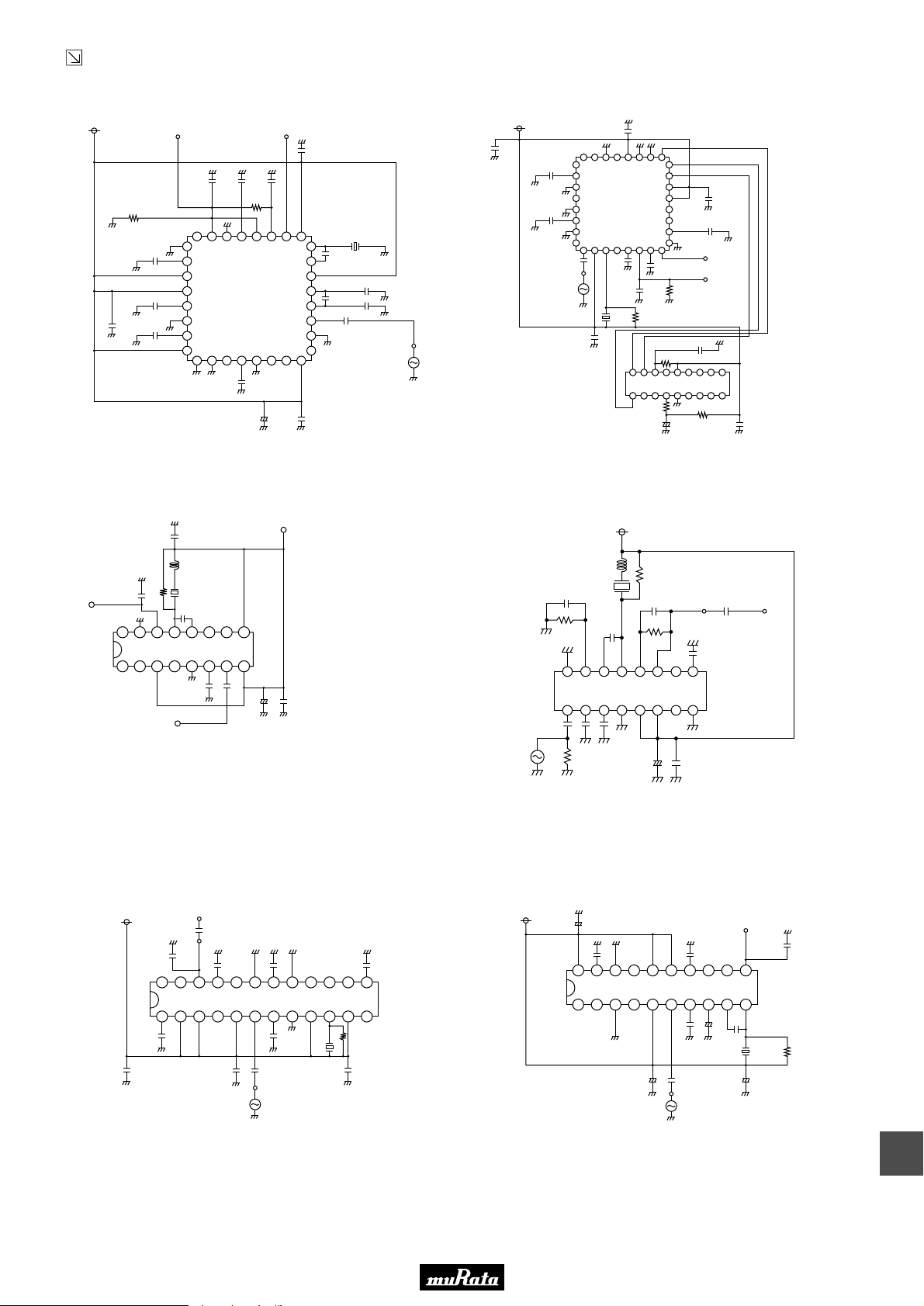
• This PDF catalog is downloaded from the website of Murata Manufacturing co., ltd. Therefore, it’s specifications are subject to change or our products in it may be discontinued without advance notice. Please check with our
!Note
• This PDF catalog has only typical specifications because there is no space for detailed specifications. Therefore, please approve our product specifications or transact the approval sheet for product specifications before ordering.
• Please read rating and !CAUTION (for storage, operating, rating, soldering, mounting and handling) in this catalog to prevent smoking and/or burning, etc.
!Note
sales representatives or product engineers before ordering.
• This catalog has only typical specifications because there is no space for detailed specifications. Therefore, please approve our product specifications or transact the approval sheet for product specifications before ordering.
Continued from the preceding page.
■ Test Circuit
Vcc (5.0V)
330p
220k
CDSCB10M7GA135-R0
25
26
0.01µ
27
TH71101, TH71102,
28
TH71111 or TH71112
29
0.01µ
30
31
0.01µ
32
1 2 3 4 5 6 7 8
(MELEXIS)
0.01µ
0.01µ1000p100p
330k
FKS-OUTAF-OUT
0.1µ
Vcc (5.0V)
0.1µ
0.01µ
1718192021222324
16
12p
C.D.
15
14
13
12
11
10
1000p
0.033µ
1000p
0.01µ
9
0.01µ
S.G.
+
X: CDSCB10M7GA135-R0
330p10µ
Unit CR: F
: Ω
CDSCB10M7GA136-R0
330p
25
26
27
TH7122
28
[Internal AFC Enabled]
29
(MELEXIS)
30
31
32
1 2 3 4 5 6 7 8
0.1µ0.01µ
330p
S.G.
C.D.
3.3k
330p
18 17 16 15 14 13 12 11 10
PIC16F84 (Control IC)
1 2 3 4 5 6 7 8 9
330p
100k
1k
1718192021222324
16
15
14
13
12
11
10
9
330p
0.01µ
FKS-OUT
AF-OUT
100k
100p
10k
+
2.2µ
X: CDSCB10M7GA136-R0
0.1µ
Unit CR: F
P50E.pdf
10.2.9
: Ω
AF OUT
0.01µ
R
0.01µ
16
TA31161 (TOSHIBA)
1 8765432
Vcc (5.0V)
0.1µ
CDSCB10M7GF072-R0
Vcc (3V)
4.7µ
X
10p
9101112131415
0.01µ
0.01µ
+
33µ 0.01µ
X : CDSCB10M7GF072-R0
R : 820
IF IN
CDSCB10M7GF123-R0
AF OUT
0.01µ
DC-OUT
3300p
24 23 22 21 20 19 18 17 16 15 14 13
1000p
TA31275FN (TOSHIBA)
1 2 3 4 5 6 7 8 9 10 11 12
0.01µ
0.01µ
0.1µ
0.1µ
0.01µ
S.S.G.
1.8k
0.1µ
X : CDSCB10M7GF123-R0
CDSCB10M7GF109-R0
Vcc (3V)
1.2µ
R
X
0.01µ
12k
8p
1000p
51k
D.C. OUT AF OUT
0.01µ
0.01µ
910111213141516
TK14588V (TOKO)
Unit C
: F
R
: Ω
L
: H
S.S.G.
0.01µ
0.01µ
0.01µ
51
87654321
+
4.7µ
0.01µ
X : CDSCB10M7GF109-R0
R : 820
Unit C
: F
R
: Ω
L
: H
CDSCB10M7GF126-R0
Vcc (5.0V)
10µ
+
0.01µ
0.01µ
20 19 18 17 16 15 14 13 12 11
NJM2295AV (JRC)
1 2 3 4 5 6 7 8 9 10
+
0.01µ
10µ
Unit CR: F
: Ω
S.G.
DC-OUT
100p
+
0.01µ
8p
10µ
C.D.
0.01µ
180
+
10µ
X : CDSCB10M7GF126-R0
Unit CR: F
: Ω
59
18
Page 62
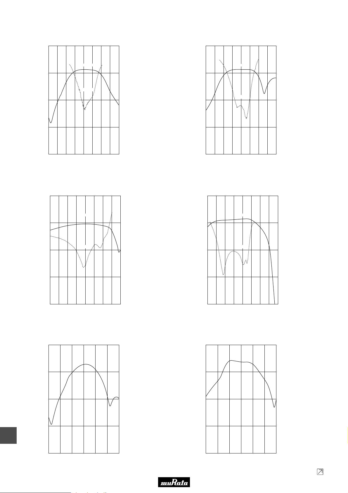
• This PDF catalog is downloaded from the website of Murata Manufacturing co., ltd. Therefore, it’s specifications are subject to change or our products in it may be discontinued without advance notice. Please check with our
!Note
• This PDF catalog has only typical specifications because there is no space for detailed specifications. Therefore, please approve our product specifications or transact the approval sheet for product specifications before ordering.
• Please read rating and !CAUTION (for storage, operating, rating, soldering, mounting and handling) in this catalog to prevent smoking and/or burning, etc.
!Note
sales representatives or product engineers before ordering.
• This catalog has only typical specifications because there is no space for detailed specifications. Therefore, please approve our product specifications or transact the approval sheet for product specifications before ordering.
■ Recovered Audio Curve
1000
CDSCB10M7GA105A-R0
100
1000
CDSCB10M7GA113-R0
100
P50E.pdf
10.2.9
AF Output
100
Distortion
10
AF Output Voltage (mV)
1
10.3 10.4 10.5 10.6 10.7 10.8 10.9 11.0 11.1
Frequency (MHz)
CDSCB10M7GA119-R0
1000
AF Output
100
AF Output
10
1
T.H.D. (%)
0.1
Input
= 100dBµ
fdev.
= ±75kHz
fmod.
= 1kHz
Vcc
= 3.0V
100
10
AF Output Voltage (mV)
1
10.3 10.4 10.5 10.6 10.7 10.8 10.9 11.0 11.1
Distortion
Frequency (MHz)
10
1
T.H.D. (%)
0.1
Input
= 100dBµ
fdev.
= ±75kHz
fmod.
= 1kHz
Vcc
= 1.2V
CDSCB10M7GA121-R0
100
10
1000
AF Output
100
100
10
10
AF Output Voltage (mV)
1
10.3 10.4 10.5 10.6 10.7 10.8 10.9 11.0 11.1
Distortion
Frequency (MHz)
CDSCB10M7GA135-R0
1000
100
10
AF Output Voltage (mV)
1
T.H.D. (%)
0.1
Input
= 100dBµ
fdev.
= ±60kHz
fmod.
= 1kHz
Vcc
= 3.0V
10
AF Output Voltage (mV)
1
10.3 10.4 10.5 10.6 10.7 10.8 10.9 11.0 11.1
Distortion
Frequency (MHz)
1
T.H.D. (%)
0.1
Input
= 100dBµ
fdev.
= ±75kHz
fmod.
= 1kHz
Vcc
= 3.2V
CDSCB10M7GA136-R0
1000
100
10
AF Output Voltage (mV)
18
60
1
0.1
10.4 10.5 10.6 10.7 10.8 10.9 11.0
Frequency (MHz)
Input
fdev.
fmod.
Vcc
= 100dBµ
= ±50kHz
= 1kHz
= 5.0V
1
0.1
10.4 10.5 10.6 10.7 10.8 10.9 11.0
Frequency (MHz)
Continued on the following page.
Input
fdev.
fmod.
Vcc
= 100dBµ
= ±50kHz
= 1kHz
= 5.0V
Page 63
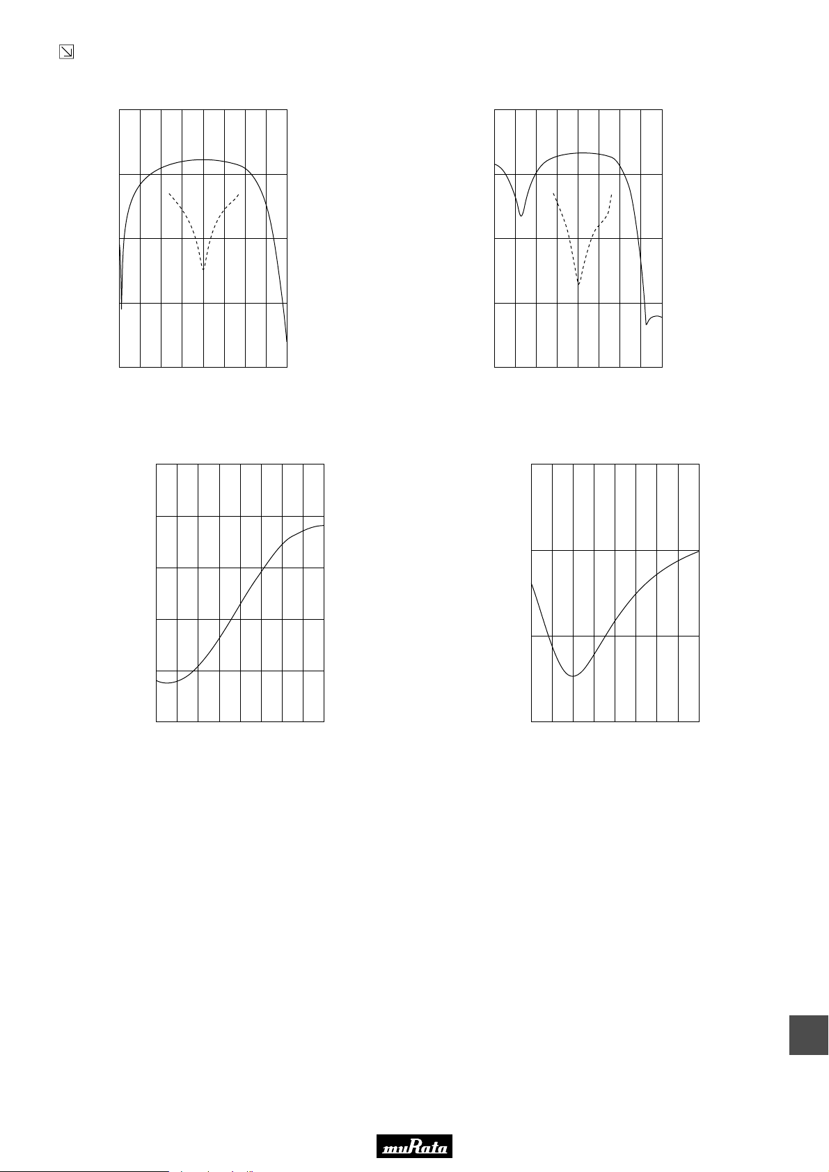
• This PDF catalog is downloaded from the website of Murata Manufacturing co., ltd. Therefore, it’s specifications are subject to change or our products in it may be discontinued without advance notice. Please check with our
!Note
• This PDF catalog has only typical specifications because there is no space for detailed specifications. Therefore, please approve our product specifications or transact the approval sheet for product specifications before ordering.
• Please read rating and !CAUTION (for storage, operating, rating, soldering, mounting and handling) in this catalog to prevent smoking and/or burning, etc.
!Note
sales representatives or product engineers before ordering.
• This catalog has only typical specifications because there is no space for detailed specifications. Therefore, please approve our product specifications or transact the approval sheet for product specifications before ordering.
Continued from the preceding page.
■ Recovered Audio Curve
CDSCB10M7GF072-R0
1000 100
1000
CDSCB10M7GF109-R0
100
P50E.pdf
10.2.9
100 10
10 1
AF Output Voltage (mV)
1 0.1
10.3 10.5 10.7 10.9 11.110.4 10.6 10.8 11.0
■ S Curve
Frequency (MHz)
CDSCB10M7GF123-R0
2.5
2.0
1.5
T.H.D. (%)
Input =
fdev. =
fmod. =
Vcc =
100dBµ
±80kHz
1kHz
3.0V
100
10
AF Output Voltage (mV)
1
10.3 10.5 10.7 10.9 11.1
10.4 10.6 10.8 11.0
Frequency (MHz)
CDSCB10M7GF126-R0
4.0
3.0
10
1
T.H.D. (%)
0.1
Input =
100dBµ
fdev. =
±64kHz
fmod. =
1kHz
Vcc =
3.0V
Volt (V)
1.0
0.5
0.0
10.3 10.4 10.5 10.6 10.7 10.8 10.9 11.0 11.1
Frequency (MHz)
Volt (V)
2.0
1.0
10.3 10.4 10.5 10.6 10.7 10.8 10.9 11.0 11.1
Frequency (MHz)
61
18
Page 64
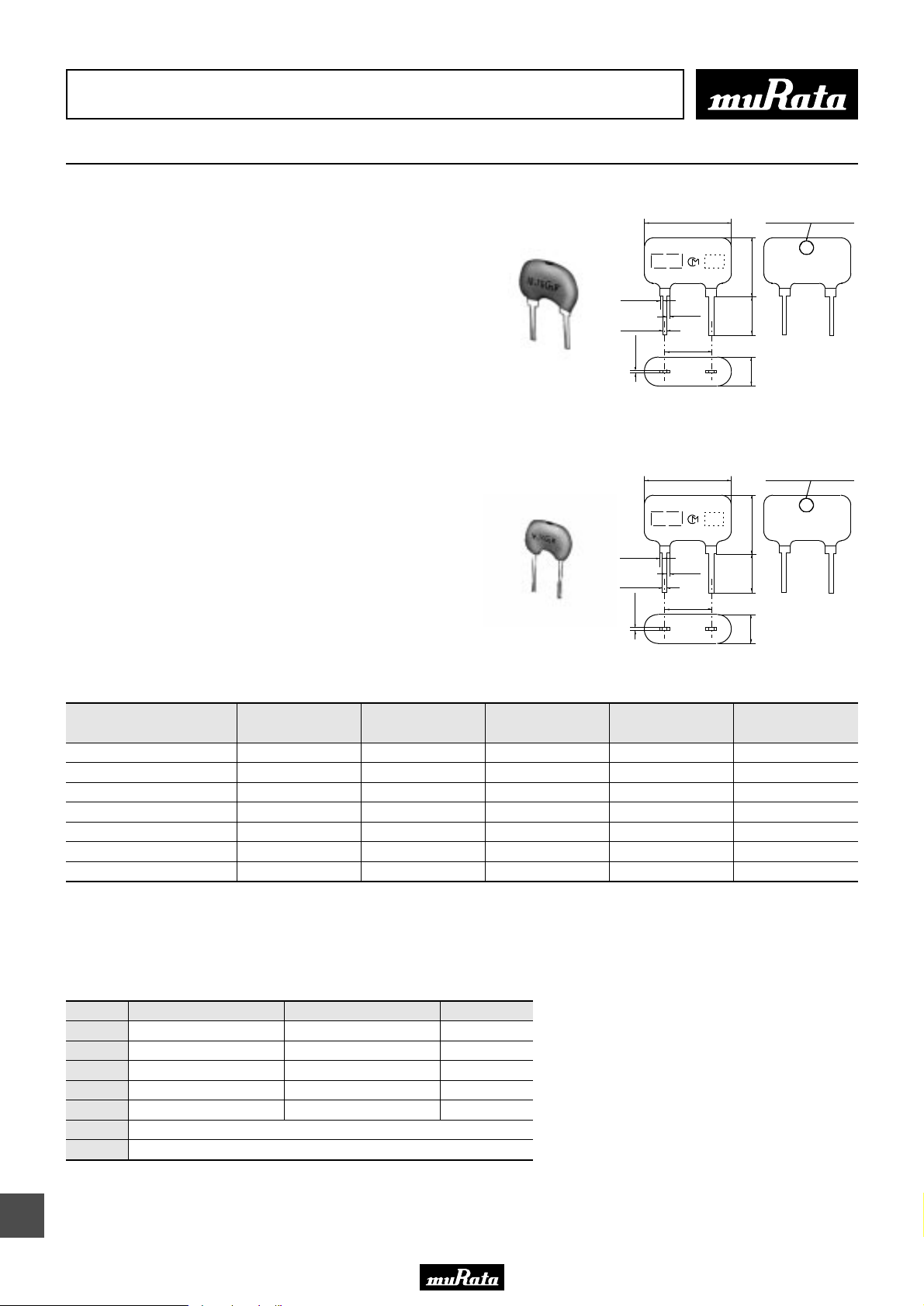
• This PDF catalog is downloaded from the website of Murata Manufacturing co., ltd. Therefore, it’s specifications are subject to change or our products in it may be discontinued without advance notice. Please check with our
!Note
• This PDF catalog has only typical specifications because there is no space for detailed specifications. Therefore, please approve our product specifications or transact the approval sheet for product specifications before ordering.
• Please read rating and !CAUTION (for storage, operating, rating, soldering, mounting and handling) in this catalog to prevent smoking and/or burning, etc.
!Note
sales representatives or product engineers before ordering.
• This catalog has only typical specifications because there is no space for detailed specifications. Therefore, please approve our product specifications or transact the approval sheet for product specifications before ordering.
CERAFILr (Filters/Traps/Discriminators) for Audio/Visual Equipment
Ceramic Discriminator 10.7MHz Standard Lead Type CDALF Series
P50E.pdf
10.2.9
CDALF10M7 series forms a resonator on a piezoelectric
ceramic substrate. In combination with ICs, this type
obtains stable demodulation characteristics in wide
bandwidths.
As part of the environment protection activity, solder
for terminal plating and terminal-element connection
inside of ceramic filter contain no lead (Pb).
■ Features
1. Compact and excellent mechanical strength
2. Can be combined with various ICs. The IC is
determined by the last number in the part number.
3. Stable demodulation characteristics can be obtained
without adjustment.
4. Stable temperature characteristics
5. Recommended combination: ceramic discriminator
CDALF10M7 series and "CERAFIL" SFELF10M7 series
of the same frequency rank.
CDALF10M7G_ Series
CDALF10M7C_ Series
0.4±0.1
0.5±0.1
0.3±0.1
0.4±0.1
0.5±0.1
0.3±0.1
M A R K I N G
M A R K I N G
8.0±1.0
0.65±0.1
5.0±0.2
8.0±1.0
0.65±0.1
5.0±0.2
E I A J
C O D E
E I A J
C O D E
Freq. Rank (Color Dot)
5.0±1.0
5.0±1.0
3.0±1.0
Freq. Rank (Color Dot)
5.0±1.0
5.0±1.0
3.0±1.0
(in mm)
(in mm)
Part Number
Center
Frequency (fo)
(MHz)
Recovered
Audio 3dB BW
(kHz)
Recovered
Audio Output
(mV)
Distortion
(%)
IC
CDALF10M7GA016-B0 10.700 ±30kHz 300 min. within60 to 90mV 0.9 max. TA8122F
CDALF10M7GA018-B0 10.700 ±30kHz 300 min. within60 to 90mV 0.9 max. TA8132N
CDALF10M7GA046-B0 10.700 ±30kHz 330 min. 280 min. 1.0 max. LA1832
CDALF10M7GA048-B0 10.700 ±30kHz 400 min. 700 min. 1.0 max. LA1835
CDALF10M7GA092-B0 10.700 ±30kHz 300 min. 60 min. 1.0 max. TA2132P
CDALF10M7CA005A-B0 10.700 ±30kHz 100 min. 600 min. 6.0 max. LA7770
CDALF10M7CA040-B0 10.700 ±30kHz 130 min. 40 min. 0.7 max. TEA5710
For safety purposes, avoid applying a direct current between the terminals.
The order quantity should be an integral multiple of the "Minimum Quantity" shown in the package page.
CDALF10M7GA018-B0: Color dot is different from standard series.
■ Standard Center Frequency Rank Code
CODE
D
B
A
C
E
Z
M
30kHz Step
10.64MHz±30kHz
10.67MHz±30kHz
10.70MHz±30kHz
10.73MHz±30kHz
10.76MHz±30kHz
25kHz Step
10.650MHz±25kHz
10.675MHz±25kHz
10.700MHz±25kHz
10.725MHz±25kHz
10.750MHz±25kHz
Combination A, B, C, D, E
Combination A, B, C
Color Code
Black
Blue
Red
Orange
White
19
62
Page 65
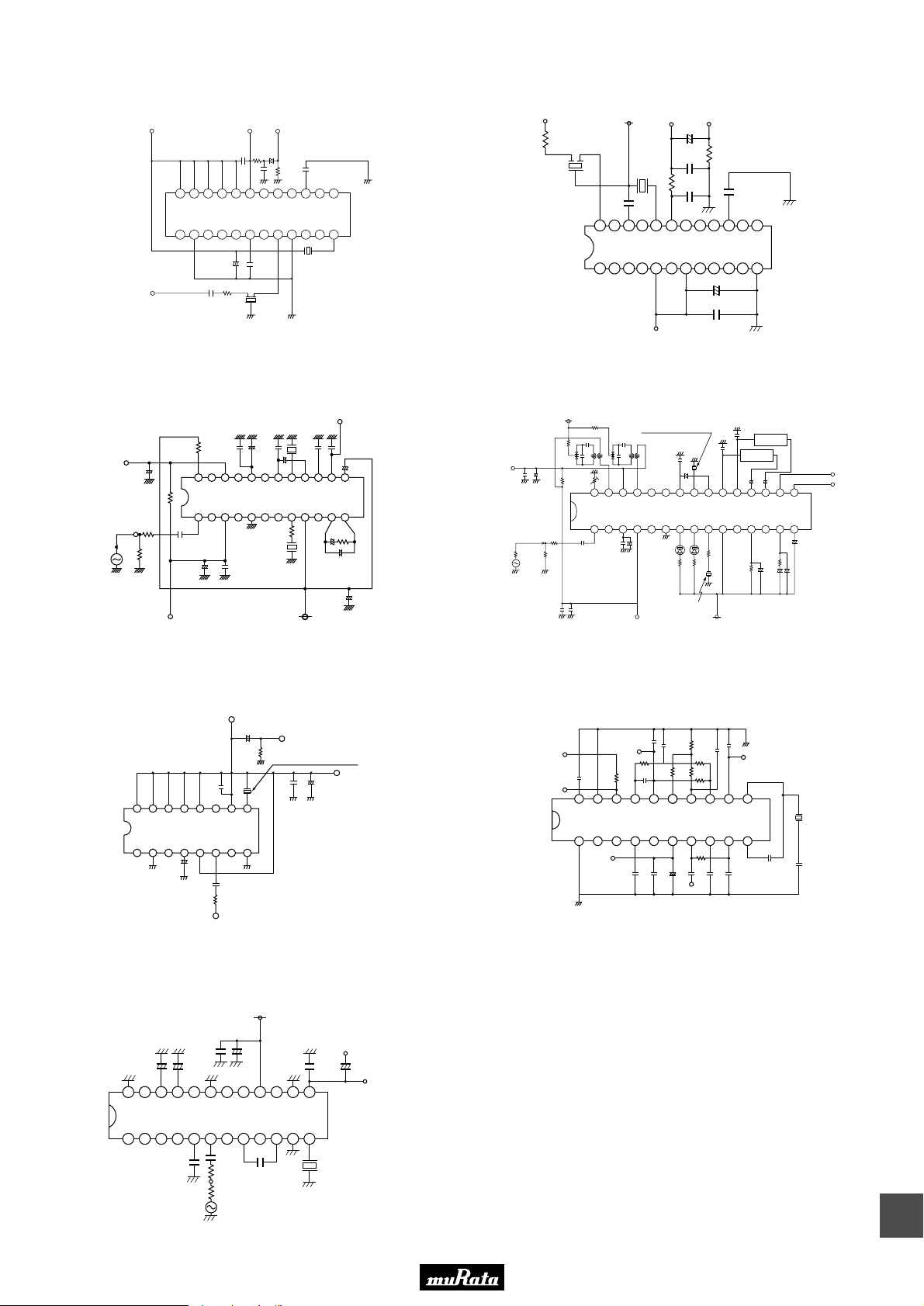
• This PDF catalog is downloaded from the website of Murata Manufacturing co., ltd. Therefore, it’s specifications are subject to change or our products in it may be discontinued without advance notice. Please check with our
!Note
• This PDF catalog has only typical specifications because there is no space for detailed specifications. Therefore, please approve our product specifications or transact the approval sheet for product specifications before ordering.
• Please read rating and !CAUTION (for storage, operating, rating, soldering, mounting and handling) in this catalog to prevent smoking and/or burning, etc.
!Note
sales representatives or product engineers before ordering.
• This catalog has only typical specifications because there is no space for detailed specifications. Therefore, please approve our product specifications or transact the approval sheet for product specifications before ordering.
■ Test Circuit
CDALF10M7GA016-B0
VCC +3V DC Out AF Out
1k
330p
2.5µ
+
24 23 22 21 20 19 18 17 16 15 14 13
TA8122F (TOSHIBA)
1 2 3 4 5 6 7 8 9 10 11 12
IF in
0.033µ
+
22µ
SFELF10M7DF00
0.022µ
0.022µ
270
24k
0.1µ
CDALF10M7GA016
Unit
R : Ω
C : F
1F in
270
SFELF10M7DF00
CDALF10M7GA018-B0
Vcc 3V
DC out AF out
2.2µ
+
0.033µ
24k
CDALF10M7GA018
1k
330p
0.022µ
24 23 22 21 20 19 18 17 16 15 14 13
0.1µ
TA8132N (TOSHIBA)
1 2 3 4 5 6 7 8 9 10 11 12
Vcc 3V
22µ
+
0.022µ
Unit
R : Ω
C : F
P50E.pdf
10.2.9
AFC
+
3.3µ
300
IF-IN
75
1611521431341251161079
CDALF10M7GA046-B0
CSBLA456KE2ZF15
0.047µ5.6k
24 1314151617181920212223
6.8k
0.047µ
REG
LA1832 (SANYO)
1 12111098765432
CDALF10M7GA046
+
10µ
0.047µ
CDALF10M7GA092-B0
DC OUT
330p
TA2132P(TOSHIBA)
+
4.7µ
270 0.01µ
IF-IN
2.2µ
+
1200p
+
22µ
20k
8
AF OUT
0.01µ
+
1µ
270
2.2µ
Vcc (5V)
AF OUT
CDALF10M7GA092
+
4.7µ
0.033µ
0.01µ
+
1µ
3k
1µ
+
Vcc(3.0V)
100µ
Unit
R : Ω
C : F
Unit
R : Ω
C : F
AFC
IF-IN
47n
DATA OUT
CDALF10M7GA048-B0
3.3µ
Vt
+
5k
15k
30 29 28 27 26 25 24 23 22 21 20 19 18 17 16
1 2 3 4 5 6 7 8 9 10 11 12 13 14 15
300
75
47n
0.047µ
10µ
0.047µ
CSBLA456KE2ZF15
+
10µ
CDALF10M7GA048
REG.
CDALF10M7CA005A-B0
DC Bias
DC Bias
+5V
0.01µ
20 19 18 17 16 15 14 13 12 11
1 2 3 4 5 6 7 8 9 10
Vcc=12V
470p
+5.2V
2k
5.6k
220p
IC : LA7770 (SANYO)
1000p
0.022p
1500p
33n
+
1µ
LA1835 (SANYO)
1k 1k
VCC(7V)
2k
0.1µ
0.1µ
10k
10k
20k
10k
50
+
33µ
-
0.01µ
0.01µ
IF IN
510
33n
470p
0.01µ
L. P. F.
10µ
10µ
20k
+
Demod.OUT
L. P. F.
++
3k
10µ
5p
Rch
Lch
1µ
0.47µ
+ +
Unit
R : Ω
C : F
CDALF10M7CA005A
0.01µ
Unit
R : Ω
C : F
CDALF10M7CA040-B0
VCC (3V)
+
+ +
0.01µ
10µ
100µ
24 23 22 21 20 19 18 17 16 15 14 13
TEA5710 (PHILIPS)
1 2 3 4 5 6 7 8 9 10 11 12
0.22µ
S.S.G.
280
50
100µ
0.01µ
0.22µ
0.01µ
AF-OUT
+
1µ
DC-OUT
Unit
R : Ω
C : F
19
63
Page 66
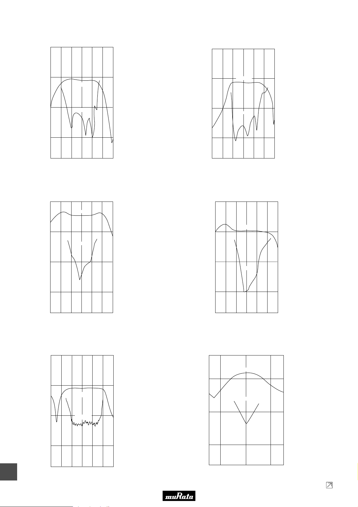
• This PDF catalog is downloaded from the website of Murata Manufacturing co., ltd. Therefore, it’s specifications are subject to change or our products in it may be discontinued without advance notice. Please check with our
!Note
• This PDF catalog has only typical specifications because there is no space for detailed specifications. Therefore, please approve our product specifications or transact the approval sheet for product specifications before ordering.
• Please read rating and !CAUTION (for storage, operating, rating, soldering, mounting and handling) in this catalog to prevent smoking and/or burning, etc.
!Note
sales representatives or product engineers before ordering.
• This catalog has only typical specifications because there is no space for detailed specifications. Therefore, please approve our product specifications or transact the approval sheet for product specifications before ordering.
■ Frequency Characteristics
1000
CDALF10M7GA016-B0
100
1000
CDALF10M7GA018-B0
100
P50E.pdf
10.2.9
Recovered AF Output Voltage (mV)
1000
100
100
10
AF Output
10
1
Distortion
10.610.5 10.7 10.8 10.9 11.010.4
Frequency (MHz)
1
Distortion (%)
0.1
Input signal conditions
Input Level
Mod. Freq.
Freq.Dev.
80dBµ
1000Hz
±22.5kHz
100
10
Recovered AF Output Voltage (mV)
1
10.4 10.5 10.6 10.7 10.8 10.9 11.0
CDALF10M7GA046-B0
100
AF Output
10
Distortion
1000
100
AF Output
Distortion
Frequency (MHz)
CDALF10M7GA048-B0
AF Output
10
1
Distortion (%)
0.1
Input signal conditions
Input Level 80dBµ
Mod. Freq. 1000Hz
Freq. Dev. ±22.5kHz
100
10
19
64
10
Distortion
Recovered AF Output Voltage (mV)
1
10.610.5 10.7 10.8 10.9 11.010.4
Frequency (MHz)
CDALF10M7CA005A-B0
5000
AF Output
1000
Distortion
100
Recovered AF Output Voltage (mV)
10
10.6 10.7 10.8
Frequency (MHz)
10.9 11.0
1
Distortion (%)
0.1
Input signal conditions
Input Level 112dBµ
Mod. Freq. 1000Hz
Freq. Dev. ±75kHz
10
Recovered AF Output Voltage (mV)
1
10.510.4 10.6 10.7
Frequency (MHz)
10.8
CDALF10M7GA092-B0
1000
100
AF Output
10
Recovered AF Output Voltage (mV)
1
Distortion
10.510.4 10.6 10.7 10.8 10.9 11.0
Frequency (MHz)
100
10
1
Distortion (%)
0.1
Input signal conditions
Input Level 80dBµ
Mod.Freq. 1000Hz
Freq.Dev. ±22.5kHz
1
Distortion (%)
0.1
Input signal conditions
Input Level
Mod. Freq.
Freq.Dev.
500
100
10
1
Input signal conditions
Input Level 100dBµ
Mod. Freq. 1000Hz
Freq. Dev. ±75kHz
112dBµ
1000Hz
±75kHz
Distortion (%)
Continued on the following page.
Page 67
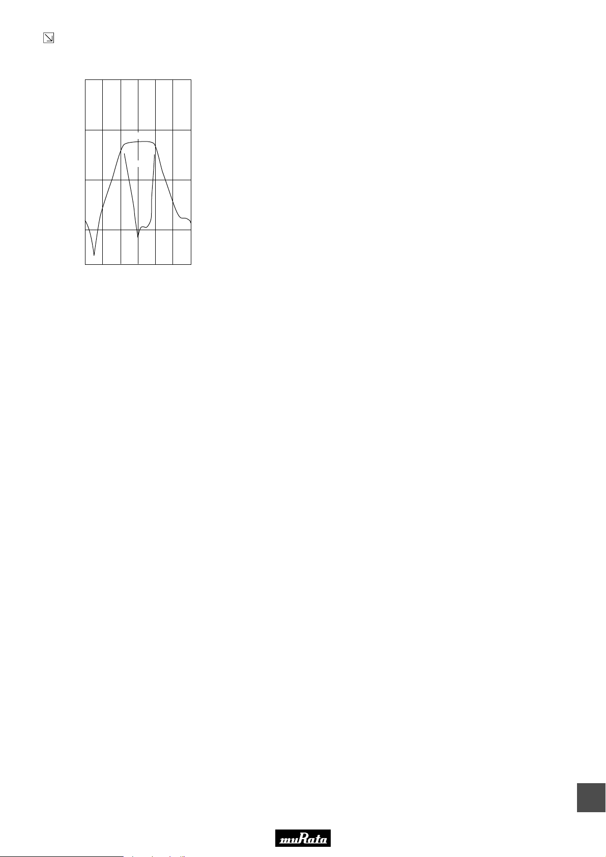
• This PDF catalog is downloaded from the website of Murata Manufacturing co., ltd. Therefore, it’s specifications are subject to change or our products in it may be discontinued without advance notice. Please check with our
!Note
• This PDF catalog has only typical specifications because there is no space for detailed specifications. Therefore, please approve our product specifications or transact the approval sheet for product specifications before ordering.
• Please read rating and !CAUTION (for storage, operating, rating, soldering, mounting and handling) in this catalog to prevent smoking and/or burning, etc.
!Note
sales representatives or product engineers before ordering.
• This catalog has only typical specifications because there is no space for detailed specifications. Therefore, please approve our product specifications or transact the approval sheet for product specifications before ordering.
Continued from the preceding page.
■ Frequency Characteristics
CDALF10M7CA040-B0
1000
100
P50E.pdf
10.2.9
100
10
Recovered AF Output Voltage (mV)
1
10.4 11.0
AF Output
Distortion
10.5 10.6 10.7 10.8 10.9
Frequency (MHz)
10
1
Distortion (%)
0.1
Input signal conditions
Input Level 100dBµ
Mod. Freq. 1000Hz
Freq. Dev. ±22.5kHz
65
19
Page 68
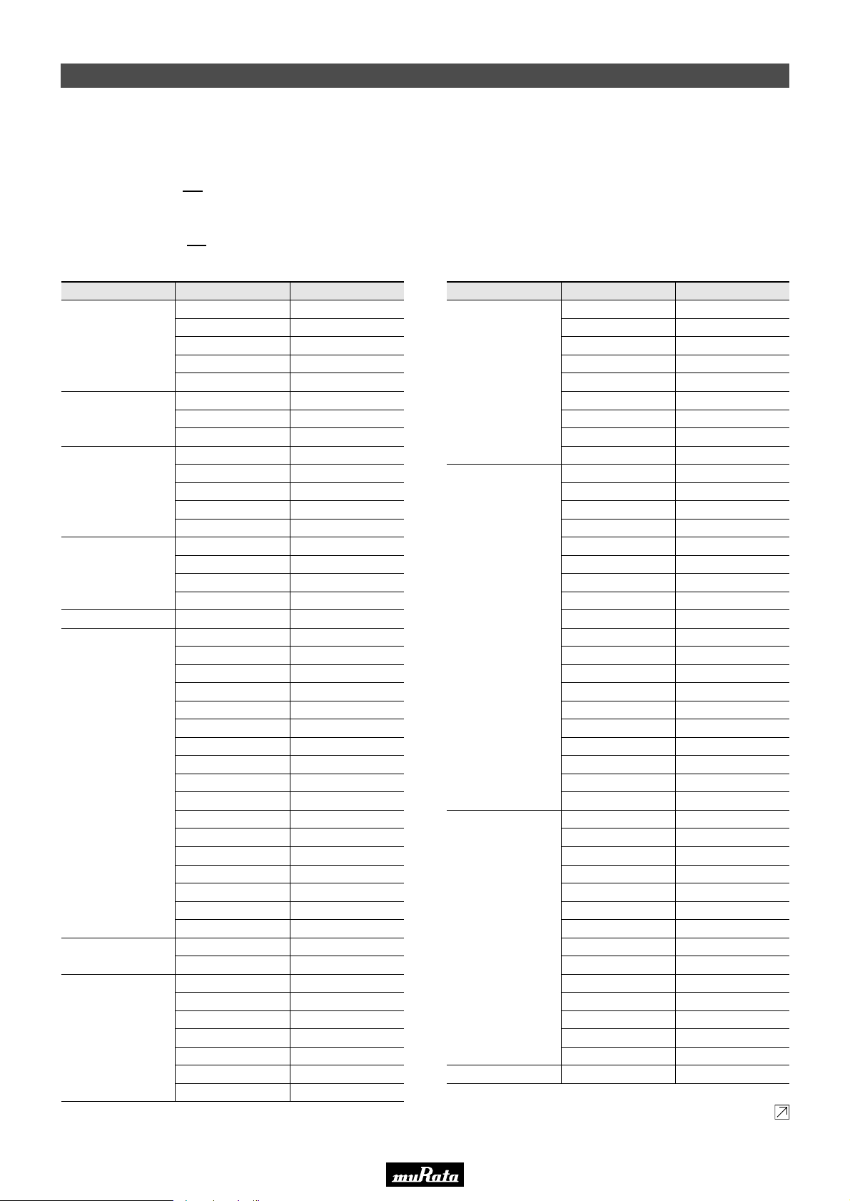
Please see following table for reference applied IC.
If you cannot find IC part number you are seeking, please contact our sales representative.
ex. : CDALF10M7GA016-B0
Suffix Number
CDSCB10M7GA105A-R0
Suffix Number
IC Manufacturer IC Part Number Suffix Number
SAMSUNG
SANYO
SONY
T. I.
KA22425
KA2244
KA22901
KA2292
KA2295
KA2297
KA2298B
KB22902
S1A0903
LA1150
LA1225M
LA1260
LA1805
LA1810
LA1814M
LA1816
LA1822
LA1823
LA1827M
LA1830
LA1831
LA1832 / M
LA1833
LA1835 / M
LA1838 / M
LA7770
LV23000M
LV23100V
CX1691M
CX-20029
CX-20076
CXA1030P
CXA1111
CXA1238
CXA1238N
CX1343M
CXA1376AM
CXA1538M / N / S
CXA1611
CXA1619B
CXA1991N
CX3067M
TRF6901
089
059
090
063
064
091
065
103
118A
070
108A
007
026
022
115
015
094
101
083
037
043
046
086
048
079
023
114
121
078
001
002
012
093
027
027N
032
054
069
075
117
068
076
119
IC Manufacturer IC Part Number Suffix Number
ATMEL
INFINEON
MATSUSHITA
MOTOROLA
NEC
PHILIPS
RFMD
ROHM
U2501B
U2765B
U4313B
U4490B
U829B
TDA1576T
TDA6160X
TDA6160-2X
AN6138SH
AN7004
AN7006S
AN7007SU
AN7232
MC13156
MC13158
MC13173
MC3363
µPC1391M
NE604
SA605
SA626
SA636DK
SA639
TBA120U
TBA229-2
TDA1596T
TDA2557
TEA5591
TEA5592
TEA5594
TEA5710
TEA5712T
TEA5757HL
TEA5762 / 5757
UAA3220TS
RF2905
RF2925
BA1440
BA1448
BA4110
BA4220
BA4230AF
BA4234L
BA4240L
028
095
081
034V
025
051
038
044
097
011
014A
013
053
049
073
052
087
056
020
042
047
096
085
029
021A
120
024
017
030
035
040
055
105A
061
098
111
104
019
060
066
041
005
004
067
Continued on the following page.
• This PDF catalog is downloaded from the website of Murata Manufacturing co., ltd. Therefore, it’s specifications are subject to change or our products in it may be discontinued without advance notice. Please check with our
!Note
• This PDF catalog has only typical specifications because there is no space for detailed specifications. Therefore, please approve our product specifications or transact the approval sheet for product specifications before ordering.
• Please read rating and !CAUTION (for storage, operating, rating, soldering, mounting and handling) in this catalog to prevent smoking and/or burning, etc.
!Note
sales representatives or product engineers before ordering.
• This catalog has only typical specifications because there is no space for detailed specifications. Therefore, please approve our product specifications or transact the approval sheet for product specifications before ordering.
Ceramic Discriminator 10.7MHz Applied IC Reference Table
P50E.pdf
10.2.9
19
66
Page 69
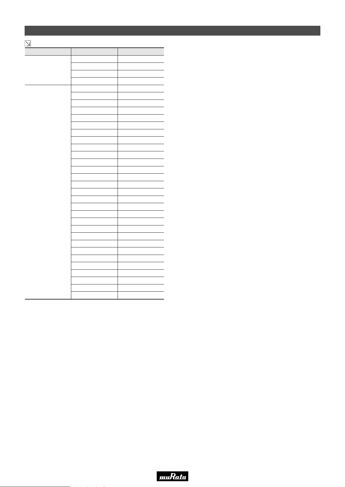
IC Manufacturer IC Part Number Suffix Number
TOKO
TOSHIBA
TK14570L
TK14581
TK14583V
TK14588V
TA2003
TA2007
TA2008A / AN
TA2022
TA2029
TA2046
TA2057
TA2099N
TA2104AFN
TA2104F
TA2111N / F / FN
TA2132
TA2132BP
TA2142FN
TA2149AN
TA2149N
TA2154FN
TA2159F
TA31161
TA31275FN
TA7130P
TA7303P
TA7640AP
TA7765AF
TA8122AN / AF
TA8132AN / AF
TA8186
TA8721ASN
TB2132FN
122
062
112
109
031
033
045
050
036
058
057
082
080
080A
077
092
092D
102
100A
100
113
116
072
123
009
008
006
071
016
018
039
088
128
Continued from the preceding page.
• This PDF catalog is downloaded from the website of Murata Manufacturing co., ltd. Therefore, it’s specifications are subject to change or our products in it may be discontinued without advance notice. Please check with our
!Note
• This PDF catalog has only typical specifications because there is no space for detailed specifications. Therefore, please approve our product specifications or transact the approval sheet for product specifications before ordering.
• Please read rating and !CAUTION (for storage, operating, rating, soldering, mounting and handling) in this catalog to prevent smoking and/or burning, etc.
!Note
sales representatives or product engineers before ordering.
• This catalog has only typical specifications because there is no space for detailed specifications. Therefore, please approve our product specifications or transact the approval sheet for product specifications before ordering.
Ceramic Discriminator 10.7MHz Applied IC Reference Table
P50E.pdf
10.2.9
67
19
Page 70
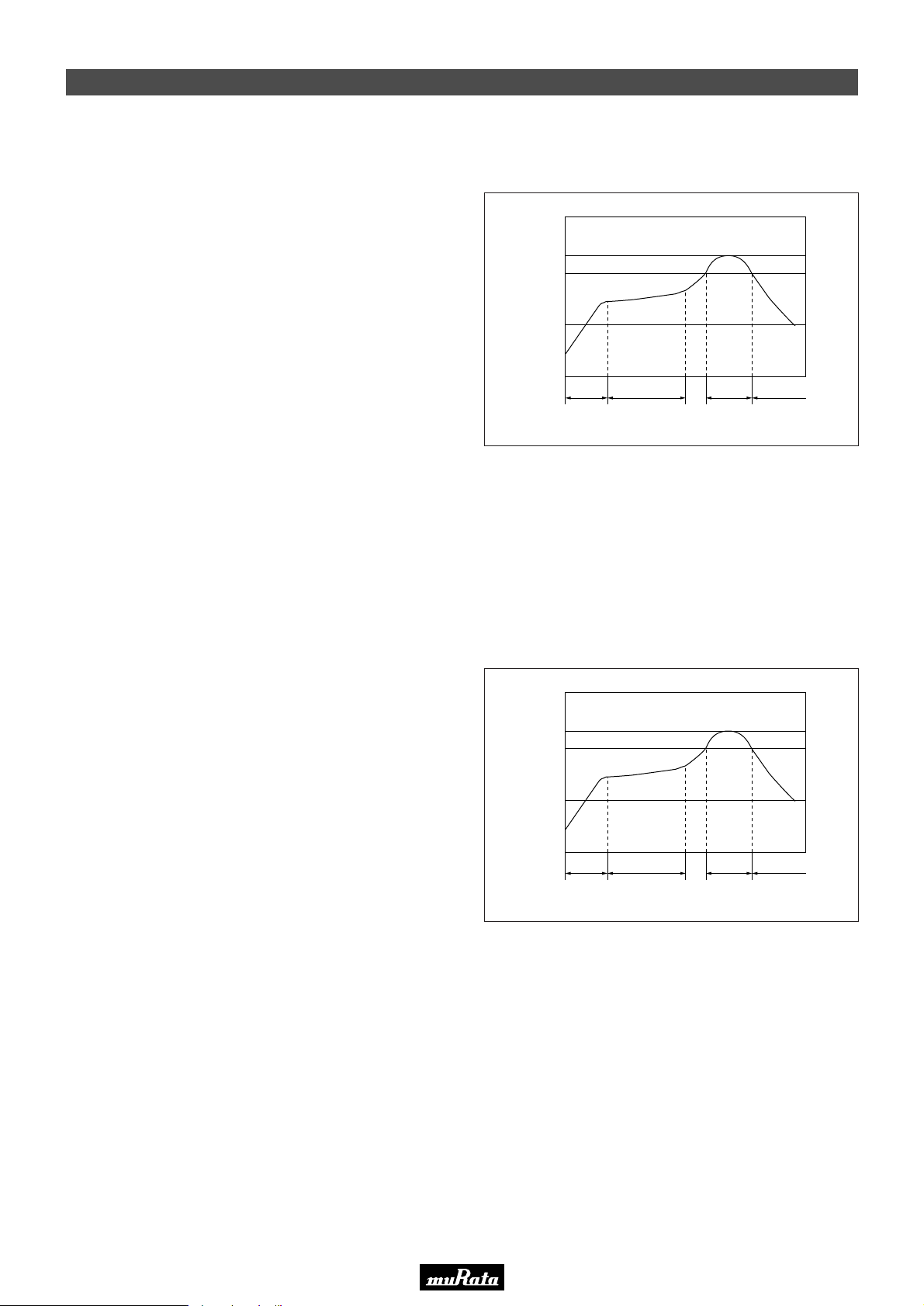
• This PDF catalog is downloaded from the website of Murata Manufacturing co., ltd. Therefore, it’s specifications are subject to change or our products in it may be discontinued without advance notice. Please check with our
!Note
• This PDF catalog has only typical specifications because there is no space for detailed specifications. Therefore, please approve our product specifications or transact the approval sheet for product specifications before ordering.
• Please read rating and !CAUTION (for storage, operating, rating, soldering, mounting and handling) in this catalog to prevent smoking and/or burning, etc.
!Note
sales representatives or product engineers before ordering.
• This catalog has only typical specifications because there is no space for detailed specifications. Therefore, please approve our product specifications or transact the approval sheet for product specifications before ordering.
Notice (Soldering and Mounting)
■ CERAFILr 10.7MHz Chip Type SFECF Series
1. Standard Reflow Soldering Conditions
(1) Reflow
Filter is soldered twice within the following temperature
conditions.
Peak
260
230
Pre-heating
100
Temperature (°C)
(150-180°C)
(260°C max.)
Heating
(230°C)
Gradual
Cooling
P50E.pdf
10.2.9
(2) Soldering Iron
Filter is soldered at +350±5°C for 3.0±0.5 seconds. The
soldering iron should not touch the filter while soldering.
2. Wash
The component cannot withstand washing.
■ CERAFILr 10.7MHz Chip Type SFECV/SFECK Series
1. Standard Reflow Soldering Conditions
(1) Reflow
Filter is soldered twice within the following temperature
conditions.
30 sec.
240
230
100
Temperature (°C)
min.
60-120 sec.
Pre-heating
(150-180°C)
40 sec.
max.
Peak
(240°C max.)
Heating
(230°C)
120 sec.
min.
Gradual
Cooling
19
(2) Soldering Iron
Filter is soldered at +350±5°C for 3.0±0.5 seconds. The
soldering iron should not touch the filter while soldering.
2. Wash
The component cannot withstand washing.
■ CERAFILr 10.7MHz Lead Type
The component cannot withstand washing.
68
30 sec.
min.
60-120 sec.
30 sec.
max.
120 sec.
min.
Page 71

• This PDF catalog is downloaded from the website of Murata Manufacturing co., ltd. Therefore, it’s specifications are subject to change or our products in it may be discontinued without advance notice. Please check with our
!Note
• This PDF catalog has only typical specifications because there is no space for detailed specifications. Therefore, please approve our product specifications or transact the approval sheet for product specifications before ordering.
• Please read rating and !CAUTION (for storage, operating, rating, soldering, mounting and handling) in this catalog to prevent smoking and/or burning, etc.
!Note
sales representatives or product engineers before ordering.
• This catalog has only typical specifications because there is no space for detailed specifications. Therefore, please approve our product specifications or transact the approval sheet for product specifications before ordering.
Notice (Soldering and Mounting)
■ CERAFILr 4.5-6.5MHz Chip Type
1. Standard Reflow Soldering Conditions
(1) Reflow
Filter is soldered twice within the following temperature
conditions.
Peak
240
230
Pre-heating
100
Temperature (°C)
(150-180°C)
(240°C max.)
Heating
(230°C)
Gradual
Cooling
P50E.pdf
10.2.9
(2) Soldering Iron
Filter is soldered at +350±5°C for 3.0±0.5 seconds. The
soldering iron should not touch the filter while soldering.
2. Wash
The component cannot withstand washing.
■ CERAFILr 2.3-5.7MHz Chip Type SFSKB Series
1. Standard Reflow Soldering Conditions
(1) Reflow
Filter is soldered twice within the following temperature
conditions.
30 sec.
260
200
100
Temperature (°C)
min.
60-120 sec.
Pre-heating
(150-170°C)
30 sec.
max.
Peak
(260°C max.)
Heating
(200°C)
120 sec.
min.
Gradual
Cooling
(2) Soldering Iron
Filter is soldered at +320±5°C for 3.0±0.5 seconds. The
soldering iron should not touch the filter while soldering.
2. Wash
The component cannot withstand washing.
■ CERAFILr 3.5-6.5MHz Lead Type
The component cannot withstand washing.
30 sec.
min.
60-120 sec.
60 sec.
max.
120 sec.
min.
19
69
Page 72
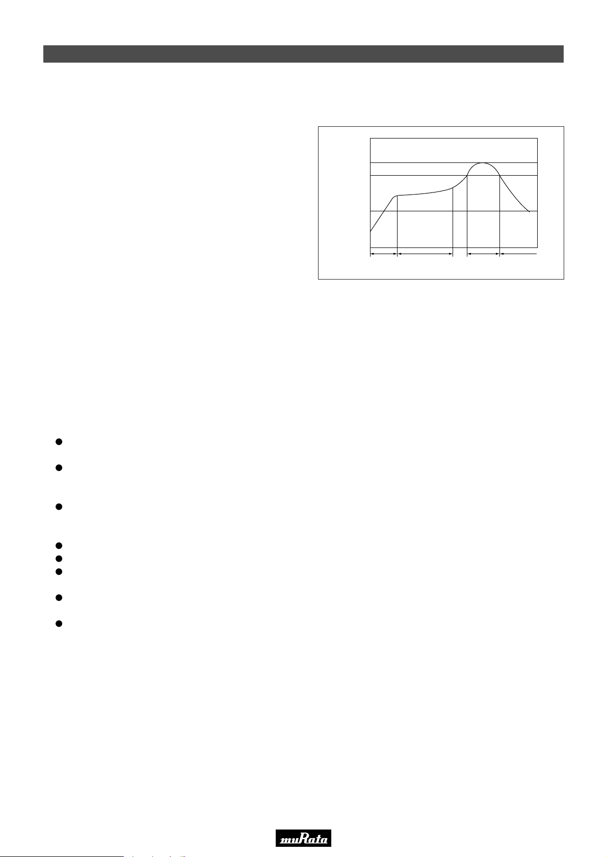
• This PDF catalog is downloaded from the website of Murata Manufacturing co., ltd. Therefore, it’s specifications are subject to change or our products in it may be discontinued without advance notice. Please check with our
!Note
• This PDF catalog has only typical specifications because there is no space for detailed specifications. Therefore, please approve our product specifications or transact the approval sheet for product specifications before ordering.
• Please read rating and !CAUTION (for storage, operating, rating, soldering, mounting and handling) in this catalog to prevent smoking and/or burning, etc.
!Note
sales representatives or product engineers before ordering.
• This catalog has only typical specifications because there is no space for detailed specifications. Therefore, please approve our product specifications or transact the approval sheet for product specifications before ordering.
Notice (Soldering and Mounting)
■ CERAFILr 455kHz Chip Type SFPKA Series
1. Standard Reflow Soldering Conditions
(1) Reflow
Filter is soldered twice within the following temperature
conditions.
260
230
100
Temperature (°C)
Pre-heating
(150-180°C)
Peak
(260°C max.)
Heating
(230°C)
P50E.pdf
10.2.9
Gradual
Cooling
(2) Soldering Iron
Electrode is directly soldered with the tip of soldering iron
at +350±5°C for 3.0±0.5 seconds.
2. Wash
(1) Cleaning Solvent
CFC alternatives (HCFC Series), Isopropyl Alcohol (IPA),
Water (Demineralized Water), Cleaning Water Solution
(Cleanthrough-750H, Pine Alpha 100S), Silicon
(Technocare FRW)
(2) Cleaning Conditions
Immersion Wash
2 minutes max. in above solvent at +60°C max.
Shower or Rinse Wash
2 minutes max. in above solvent at +60°C max.
(3) Notice
When components are immersed in solvent, be sure to
maintain the temperature of components below the
temperature of solvent.
Please do not use ultrasonic cleaning.
Total washing time should be within 4 minutes.
Please ensure the component is thoroughly evaluated
in your application circuit.
Please do not use chlorine, petroleum and alkaline
cleaning solvents.
If you plan to use any other type of solvents, please
consult with Murata or Murata representative prior to
using.
30 sec.
min.
60-120 sec. 40 sec.
max.
120 sec.
min.
19
■ CERAFILr 455kHz Lead Type
The component cannot withstand washing.
70
Page 73
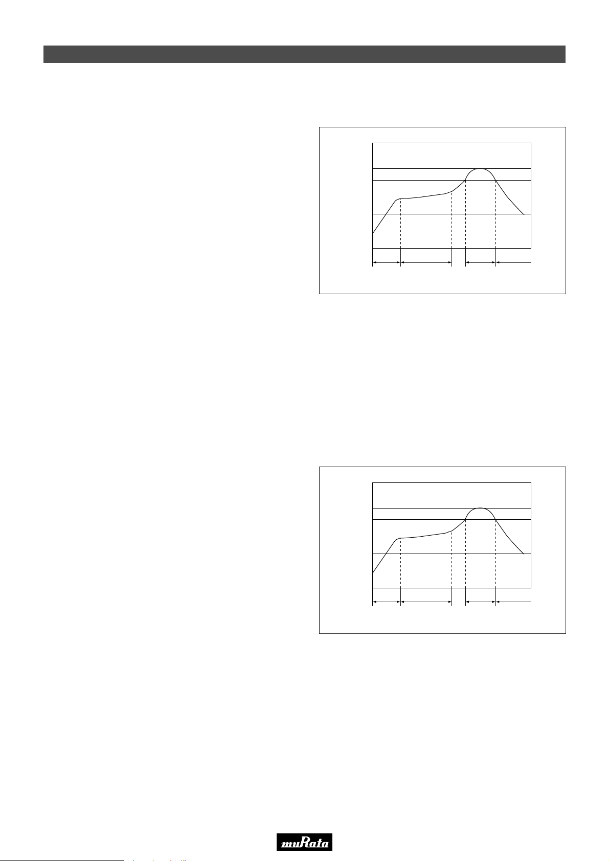
• This PDF catalog is downloaded from the website of Murata Manufacturing co., ltd. Therefore, it’s specifications are subject to change or our products in it may be discontinued without advance notice. Please check with our
!Note
• This PDF catalog has only typical specifications because there is no space for detailed specifications. Therefore, please approve our product specifications or transact the approval sheet for product specifications before ordering.
• Please read rating and !CAUTION (for storage, operating, rating, soldering, mounting and handling) in this catalog to prevent smoking and/or burning, etc.
!Note
sales representatives or product engineers before ordering.
• This catalog has only typical specifications because there is no space for detailed specifications. Therefore, please approve our product specifications or transact the approval sheet for product specifications before ordering.
Notice (Soldering and Mounting)
■ Ceramic Trap 4.5-6.5MHz Chip Type
1. Standard Reflow Soldering Conditions
(1) Reflow
Filter is soldered twice within the following temperature
conditions.
Peak
240
230
Pre-heating
100
Temperature (°C)
(150-180°C)
(240°C max.)
Heating
(230°C)
Gradual
Cooling
P50E.pdf
10.2.9
(2) Soldering Iron
Filter is soldered at +350±5°C for 3.0±0.5 seconds. The
soldering iron should not touch the filter while soldering.
2. Wash
The component cannot withstand washing.
■ Ceramic Trap 3.5-6.5MHz Lead Type
The component cannot withstand washing.
■ Ceramic Discriminator 10.7MHz Chip Type
1. Standard Reflow Soldering Conditions
(1) Reflow
Filter is soldered twice within the following temperature
conditions.
30 sec.
260
230
100
Temperature (°C)
min.
60-120 sec.
Pre-heating
(150-180°C)
30 sec.
max.
Peak
(260°C max.)
Heating
(230°C)
120 sec.
min.
Gradual
Cooling
(2) Soldering Iron
Filter is soldered at +300±5°C for 3.0±0.5 seconds. The
soldering iron should not touch the filter while soldering.
2. Wash
The component cannot withstand washing.
■ Ceramic Discriminator 10.7MHz Lead Type
The component cannot withstand washing.
■ Ceramic Discriminator 3.5-6.5MHz
The component cannot withstand washing.
30 sec.
min.
60-120 sec.
40 sec.
max.
120 sec.
min.
19
71
Page 74
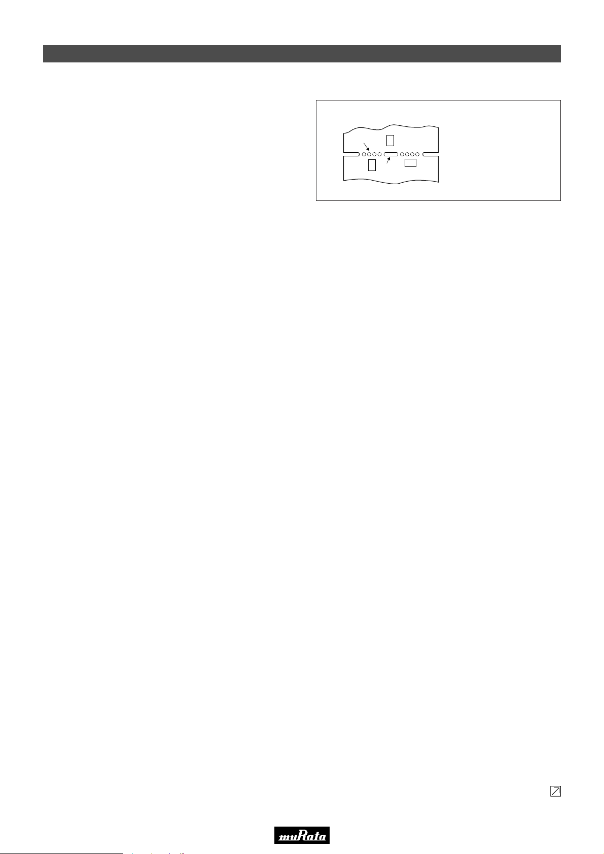
• This PDF catalog is downloaded from the website of Murata Manufacturing co., ltd. Therefore, it’s specifications are subject to change or our products in it may be discontinued without advance notice. Please check with our
!Note
• This PDF catalog has only typical specifications because there is no space for detailed specifications. Therefore, please approve our product specifications or transact the approval sheet for product specifications before ordering.
• Please read rating and !CAUTION (for storage, operating, rating, soldering, mounting and handling) in this catalog to prevent smoking and/or burning, etc.
!Note
sales representatives or product engineers before ordering.
• This catalog has only typical specifications because there is no space for detailed specifications. Therefore, please approve our product specifications or transact the approval sheet for product specifications before ordering.
Notice (Handling)
■ CERAFILr 10.7MHz Chip Type SFECF Series
1. The component will be damaged when an excessive
stress is applied.
2. The component may be damaged if excess mechanical
stress is applied to it mounted on the printed circuit
board.
3. Design layout of components on the PC board to
minimize the stress imposed on the warp or flexure of the
board.
4. After installing chips, if solder is excessively applied to
the circuit board, mechanical stress will cause destruction
resistance characteristics to lower. To prevent this, be
extremely careful in determining shape and dimension
before designing the circuit board diagram.
5. The component may be damaged during mounting
process if some part of mounter such as positioning
claws or nozzle are worn down. The regular maintenance
recommended for mounters should be done to prevent
trouble.
6. The component is recommended with placement
machines which employ optical placement capabilities.
The component might be damaged by excessive
mechanical force. Please make sure that you have
evaluated by using placement machines before going into
mass production. Do not use placement machines which
utilize mechanical positioning. Please contact Murata for
details beforehand.
7. When correcting chips with a soldering iron, the tip of the
soldering iron should not directly touch the chip
component. Depending on the soldering conditions, the
effective area of terminations may be reduced. The use
of solder containing Ag should be done to prevent the
electrode erosion.
8. Do not clean or wash the component as it is not
hermetically sealed.
9. In case of covering filter with over coat, conditions such
as material of resin, cure temperature, and so on should
be evaluated carefully.
10. Do not use strong acidity flux, more than 0.2wt%
chlorine content, in re-flow soldering.
11. Accurate test circuit values are required to measure
electrical characteristics.
It may be a cause of miscorrelation if there is any
deviation, especially stray capacitance, from the test
circuit in the specification.
12. The components, packed in the moisture proof bag (dry
pack), are sensitive to moisture. The following treatment
is required before applying re-flow soldering. To avoid
reliability degradation caused by thermal stress, when
unpacked, store the component in an atmosphere at
30°C and below 60%R.H., and solder within 1 week.
13. For safety purposes, connect the output of filters to the
IF amplifier through a D.C. blocking capacitor. Avoid
applying a direct current to the output of ceramic filters.
19
[Component Layout Close to Board]
Perforation
B
A
C
Slit
Continued on the following page.
Susceptibility to
stress is in the order
of : A>C>B
P50E.pdf
10.2.9
72
Page 75
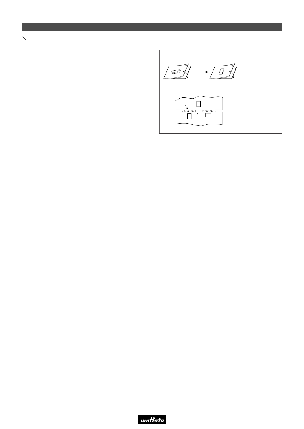
• This PDF catalog is downloaded from the website of Murata Manufacturing co., ltd. Therefore, it’s specifications are subject to change or our products in it may be discontinued without advance notice. Please check with our
!Note
• This PDF catalog has only typical specifications because there is no space for detailed specifications. Therefore, please approve our product specifications or transact the approval sheet for product specifications before ordering.
• Please read rating and !CAUTION (for storage, operating, rating, soldering, mounting and handling) in this catalog to prevent smoking and/or burning, etc.
!Note
sales representatives or product engineers before ordering.
• This catalog has only typical specifications because there is no space for detailed specifications. Therefore, please approve our product specifications or transact the approval sheet for product specifications before ordering.
Notice (Handling)
Continued from the preceding page.
■ CERAFILr 10.7MHz Chip Type SFECV/SFECK Series
1. The component will be damaged when an excessive
stress is applied.
2. The component may be damaged if excess mechanical
stress is applied to it mounted on the printed circuit
board.
3. Design layout of components on the PC board to
minimize the stress imposed on the warp or flexure of the
board.
4. After installing chips, if solder is excessively applied to
the circuit board, mechanical stress will cause
destruction resistance characteristics to lower. To
prevent this, be extremely careful in determining shape
and dimension before designing the circuit board
diagram.
5. The component may be damaged during mounting
process if some part of mounter such as positioning
claws or nozzle are worn down. The regular maintenance
recommended for mounters should be done to prevent
troubles.
6. The component is recommended with placement
machines which employ optical placement capabilities.
The component might be damaged by excessive
mechanical force. Please make sure that you have
evaluated by using placement machines before going
into mass production. Do not use placement machines
which utilize mechanical positioning. Please contact
Murata for details beforehand.
7. When correcting chips with a soldering iron, the tip of the
soldering iron should not directly touch the chip
component. Depending on the soldering conditions, the
effective area of terminations may be reduced. The use
of solder containing Ag should be done to prevent the
electrode erosion.
8. Do not clean or wash the component as it is not
hermetically sealed.
9. In case of covering filter with over coat, conditions such
as material of resin, cure temperature, and so on should
be evaluated carefully.
10. Do not use strong acidity flux, more than 0.2wt%
chlorine content, in re-flow soldering.
11. Accurate test circuit values are required to measure
electrical characteristics. It may be a cause of miscorrelation if there is any deviation, especially stray
capacitance, from the test circuit in the specification.
12. For safety purposes, connect the output of filters to the
IF amplifier through a D.C. blocking capacitor. Avoid
applying a direct current to the output of ceramic filters.
[Component Direction]
[Component Layout Close to Board]
Perforation
B
A
C
Slit
Susceptibility to
stress is in the order
of : A>C>B
P50E.pdf
10.2.9
Put the
component
lateral to the
direction in
which stress
acts.
73
19
Page 76
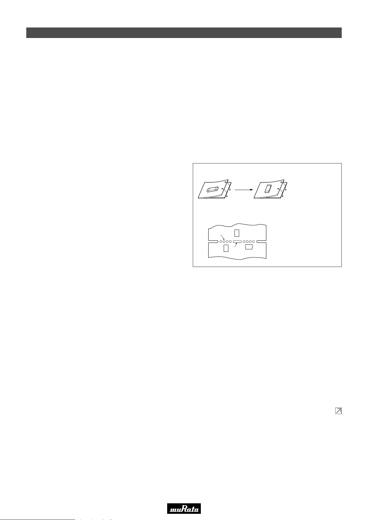
• This PDF catalog is downloaded from the website of Murata Manufacturing co., ltd. Therefore, it’s specifications are subject to change or our products in it may be discontinued without advance notice. Please check with our
!Note
• This PDF catalog has only typical specifications because there is no space for detailed specifications. Therefore, please approve our product specifications or transact the approval sheet for product specifications before ordering.
• Please read rating and !CAUTION (for storage, operating, rating, soldering, mounting and handling) in this catalog to prevent smoking and/or burning, etc.
!Note
sales representatives or product engineers before ordering.
• This catalog has only typical specifications because there is no space for detailed specifications. Therefore, please approve our product specifications or transact the approval sheet for product specifications before ordering.
Notice (Handling)
■ CERAFILr 10.7MHz Lead Type
1. Do not use this product with bend. The component
may be damaged if excess mechanical stress is
applied to it mounted on the printed circuit board.
2. The component may be damaged when an excessive
stress is applied.
3. All kinds of re-flow soldering must not be applied
on the component.
4. Do not clean or wash the component as it is not
hermetically sealed.
5. Do not use strong acidity flux, more than 0.2wt%
chlorine content, in flow soldering.
■ CERAFILr 4.5-6.5MHz Chip Type
1. The component may be damaged if excess mechanical
stress is applied to it mounted on the printed circuit
board.
2. Design layout of components on the PC board to
minimize the stress imposed on the warp or flexure of the
board.
3. After installing chips, if solder is excessively applied to
the circuit board, mechanical stress will cause destruction
resistance characteristics to lower. To prevent this, be
extremely careful in determining shape and dimension
before designing the circuit board diagram.
4. The component may be damaged during mounting
process if some part of mounter such as positioning
claws or nozzle are worn down. The regular maintenance
recommended for mounters should be done to prevent
troubles.
5. When correcting chips with a soldering iron, the tip of the
soldering iron should not directly touch the chip
component.
6. Cleaning or washing of the component is not acceptable
due to non sealed construction.
7. In case of covering filter with over coat, conditions such
as material of resin, cure temperature, and so on should
be evaluated carefully.
8. Accurate test circuit values are required to measure
electrical characteristics. It may be a cause of
miscorrelation if there is any deviation, especially stray
capacitance, from the test circuit in the specification.
9. For safety purposes, connect the output of filters to the IF
amplifier through a D.C. blocking capacitor. Avoid
applying a direct current to the output of ceramic filters.
6. In case of covering discriminator with over coat,
conditions such as material of resin, cure
temperature, and so on should be evaluated
carefully.
7. Accurate test circuit values are required to
measure electrical characteristics. It may be a
cause of miscorrelation if there is any deviation,
especially stray capacitance, from the test
circuit in the specification.
8. For safety purposes, avoid applying a direct
current between the terminals.
[Component Direction]
[Component Layout Close to Board]
Perforation
B
A
C
Slit
Susceptibility to
stress is in the order
of : A>C>B
Continued on the following page.
P50E.pdf
10.2.9
Put the component lateral to
the direction in
which stress
acts.
19
74
Page 77
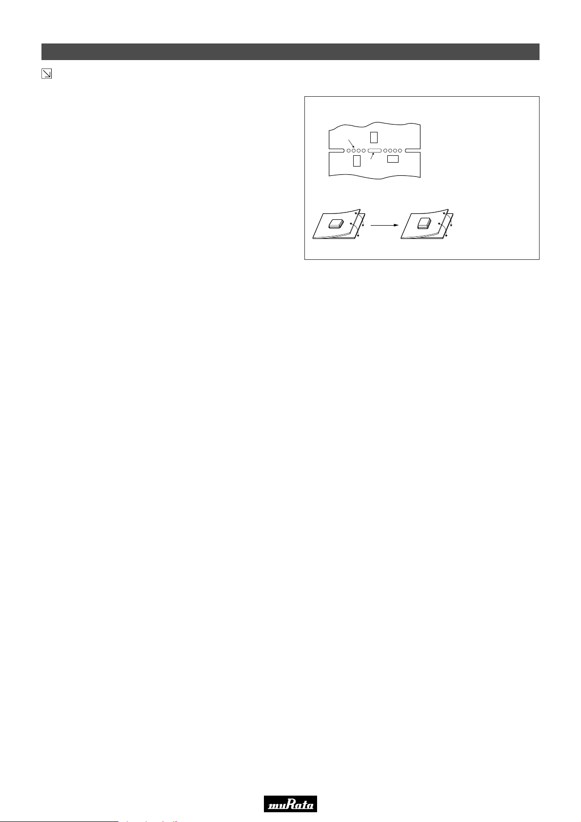
• This PDF catalog is downloaded from the website of Murata Manufacturing co., ltd. Therefore, it’s specifications are subject to change or our products in it may be discontinued without advance notice. Please check with our
!Note
• This PDF catalog has only typical specifications because there is no space for detailed specifications. Therefore, please approve our product specifications or transact the approval sheet for product specifications before ordering.
• Please read rating and !CAUTION (for storage, operating, rating, soldering, mounting and handling) in this catalog to prevent smoking and/or burning, etc.
!Note
sales representatives or product engineers before ordering.
• This catalog has only typical specifications because there is no space for detailed specifications. Therefore, please approve our product specifications or transact the approval sheet for product specifications before ordering.
Notice (Handling)
Continued from the preceding page.
■ CERAFILr 2.3-5.7MHz Chip Type SFSKB Series
The component will be damaged when an excessive
1.
stress is applied.
The component may be damaged if excess mechanical
2.
stress is applied to it mounted on the printed circuit
board.
Design layout of components on the PC board to
3.
minimize the stress imposed on the warp or flexure of the
board.
After installing chips, if solder is excessively applied to
4.
the circuit board, mechanical stress will cause destruction
resistance characteristics to lower. To prevent this, be
extremely careful in determining shape and dimension
before designing the circuit board diagram.
The component may be damaged during mounting
5.
process if some part of mounter such as positioning
claws, nozzle are worn down. The regular maintenance
recommended for mounters should be done to prevent
the troubles.
The component is recommended with placement
6.
machines which employ optical placement capabilities.
The component might be damaged by excessive
mechanical force. Please make sure that you have
evaluated by using placement machines before going into
mass production. Do not use placement machines which
utilize mechanical positioning. Please contact Murata for
details beforehand.
When correcting chips with a soldering iron, the tip of the
7.
soldering iron should not directly touch the chip
component. Depending on the soldering conditions, the
effective area of terminations may be reduced. The use of
solder containing Ag should be done to prevent the
electrode erosion.
Do not clean or wash the component as it is not
8.
hermetically sealed.
In case of covering filter with over coat, conditions such
9.
as material of resin, cure temperature, and so on should
be evaluated carefully.
Do not use strong acidity flux, more than 0.2wt%
10.
chlorine content, in re-flow soldering.
Accurate test circuit values are required to measure
11.
electrical characteristics. It may be a cause of
miscorrelation if there is any deviation, especially stray
capacitance, from the test circuit in the specification.
For safety purposes, connect the output of filters to the
12.
IF amplifier through a D.C. blocking capacitor. Avoid
applying a direct current to the output of ceramic filters.
[Component Layout Close to Board]
Perforation
B
A
C
Slit
[Component Direction]
Susceptibility to
stress is in the order
of : A>C>B
P50E.pdf
10.2.9
Put the component laterally to
the direction in
which stress
acts.
75
19
Page 78

• This PDF catalog is downloaded from the website of Murata Manufacturing co., ltd. Therefore, it’s specifications are subject to change or our products in it may be discontinued without advance notice. Please check with our
!Note
• This PDF catalog has only typical specifications because there is no space for detailed specifications. Therefore, please approve our product specifications or transact the approval sheet for product specifications before ordering.
• Please read rating and !CAUTION (for storage, operating, rating, soldering, mounting and handling) in this catalog to prevent smoking and/or burning, etc.
!Note
sales representatives or product engineers before ordering.
• This catalog has only typical specifications because there is no space for detailed specifications. Therefore, please approve our product specifications or transact the approval sheet for product specifications before ordering.
Notice (Handling)
■ CERAFILr 3.5-6.5MHz Lead Type
1. Do not use this product with bend. The component
may be damaged if excess mechanical stress is
applied to it mounted on the printed circuit board.
2. The component may be damaged when an excessive
stress is applied.
3. All kinds of re-flow soldering must not be applied
on the component.
4. Do not clean or wash the component as it is not
hermetically sealed.
5. Please contact Murata or Murata representative for
soldering condition, in case of using lead free
solder.
6. Do not use strong acidity flux, more than 0.2wt%
chlorine content, in flow soldering.
7. In case of covering filter with over coat,
conditions such as material of resin, cure
temperature, and so on should be evaluated
carefully.
8. Accurate test circuit values are required to
measure electrical characteristics. It may be a
cause of miscorrelation if there is any
deviation, especially stray capacitance, from the
test circuit in the specification.
9. For safety purposes, connect the output of filters
to the IF amplifier through a D.C. blocking
capacitor. Avoid applying a direct current to the
output of ceramic filters.
P50E.pdf
10.2.9
■ CERAFILr 455kHz Chip Type SFPKA Series
1. The component will be damaged when an excessive
stress is applied.
2. In the case that the component is cleaned, confirm
that no reliability degradation is created.
3. In case of covering filter with over coat,
conditions such as material of resin, cure
temperature, and so on should be evaluated
carefully.
4. Do not use strong acidity flux, more than 0.2wt%
chlorine content, in re-flow soldering.
■ CERAFILr 455kHz Lead Type
1. Do not use this product with bend. The component
may be damaged if excessive mechanical stress is
applied to it mounted on the printed circuit board.
2. The component will be damaged when an excessive
stress is applied.
3. All kinds of re-flow soldering must not be applied
on the component.
4. Do not clean or wash the component as it is not
hermetically sealed.
5. Do not use strong acidity flux, more than 0.2wt%
chlorine content, in flow soldering.
6. In case of covering filter with over coat,
conditions such as material of resin, cure
temperature, and so on should be evaluated
carefully.
5. The product, packed in the moisture-proof bag
(dry pack), is sensitive to moisture. The following
treatment is required before applying re-flow
soldering, to avoid package cracks or reliability
degradation caused by thermal stress. When unpacked,
store the component in an atmosphere of below 25
degree C and below 65%R.H., and solder within 48
hours.
6. For safety purposes, connect the output of filters
to the IF amplifier through a D.C. blocking
capacitor. Avoid applying a direct current to the
output of ceramic filters.
7. Accurate test circuit values are required to
measure electrical characteristics.
It may be a cause of miscorrelation if there is
any deviation, especially stray capacitance, from
the test circuit in the specification.
8. For safety purposes, connect the output of filters
to the IF amplifier through a D.C. blocking
capacitor. Avoid applying a direct current to the
output of ceramic filters.
19
76
Page 79
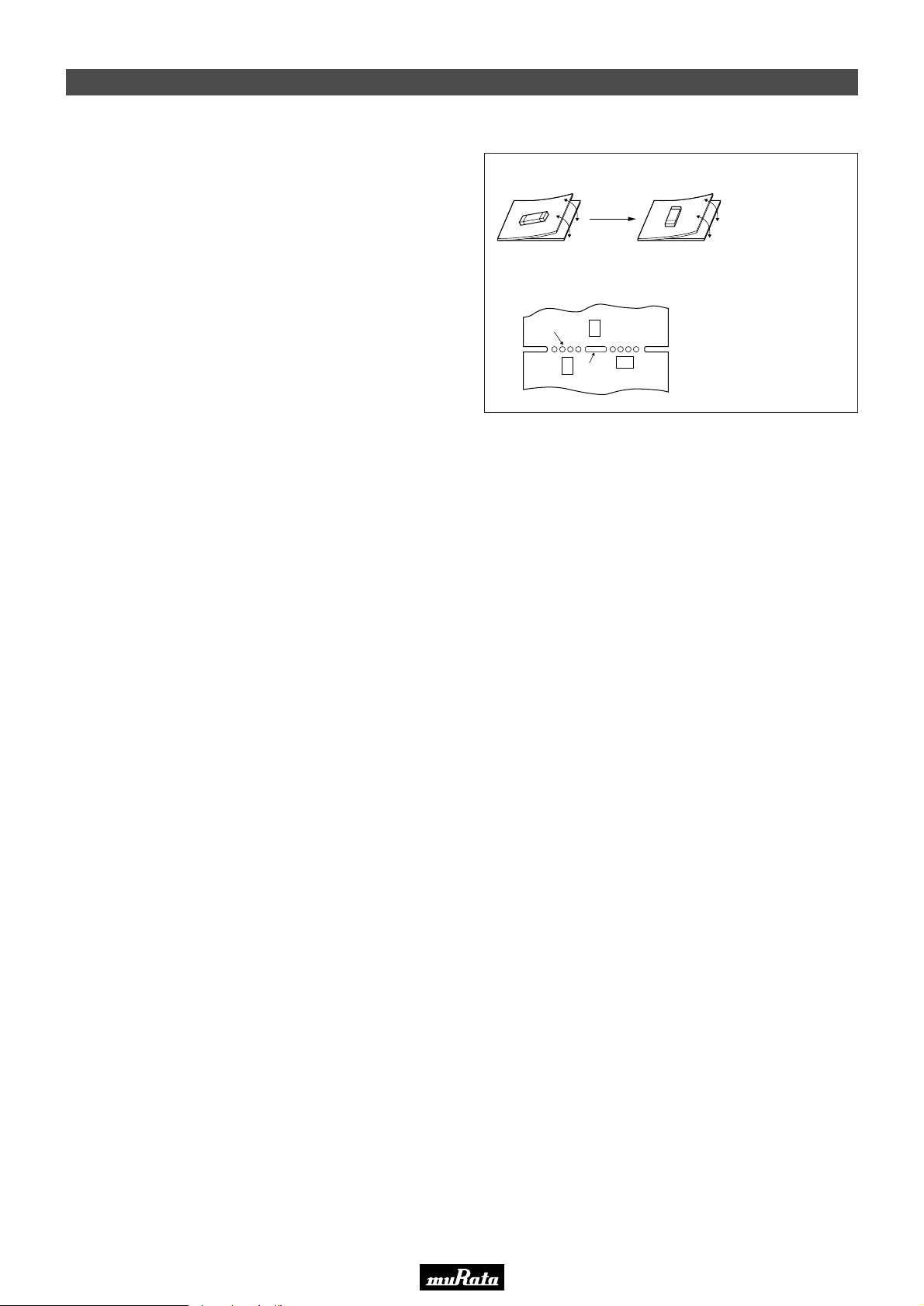
• This PDF catalog is downloaded from the website of Murata Manufacturing co., ltd. Therefore, it’s specifications are subject to change or our products in it may be discontinued without advance notice. Please check with our
!Note
• This PDF catalog has only typical specifications because there is no space for detailed specifications. Therefore, please approve our product specifications or transact the approval sheet for product specifications before ordering.
• Please read rating and !CAUTION (for storage, operating, rating, soldering, mounting and handling) in this catalog to prevent smoking and/or burning, etc.
!Note
sales representatives or product engineers before ordering.
• This catalog has only typical specifications because there is no space for detailed specifications. Therefore, please approve our product specifications or transact the approval sheet for product specifications before ordering.
Notice (Handling)
■ Ceramic Trap 4.5-6.5MHz Chip Type
1. The component may be damaged if excess mechanical
stress is applied to it mounted on the printed circuit
board.
2. Design layout of components on the PC board to
minimize the stress imposed on the warp or flexure of the
board.
3. After installing chips, if solder is excessively applied to
the circuit board, mechanical stress will cause destruction
resistance characteristics to lower. To prevent this, be
extremely careful in determining shape and dimension
before designing the circuit board diagram.
4. The component may be damaged during mounting
process if some part of mounter such as positioning
claws or nozzle are worn down. The regular maintenance
recommended for mounters should be done to prevent
troubles.
5. When correcting chips with a soldering iron, the tip of the
soldering iron should not directly touch the chip
component.
6. Cleaning or washing of the component is not acceptable
due to non sealed construction.
7. In case of covering filter with over coat, conditions such
as material of resin, cure temperature, and so on should
be evaluated carefully.
8. Accurate test circuit values are required to measure
electrical characteristics. It may be a cause of
miscorrelation if there is any deviation, especially stray
capacitance, from the test circuit in the specification.
9. For safety purposes, connect the output of filters to the IF
amplifier through a D.C. blocking capacitor. Avoid
applying a direct current to the output of ceramic filters.
[Component Direction]
[Component Layout Close to Board]
Perforation
B
A
C
Slit
Susceptibility to
stress is in the order
of : A>C>B
P50E.pdf
10.2.9
Put the component lateral to
the direction in
which stress
acts.
■ Ceramic Trap 3.5-6.5MHz Lead Type
1. Do not use this product with bend. The component
may be damaged if excess mechanical stress is
applied to it mounted on the printed circuit board.
2. The component may be damaged when an excessive
stress is applied.
3. All kinds of re-flow soldering must not be applied
on the component.
4. Do not clean or wash the component as it is not
hermetically sealed.
5. Please contact Murata or Murata representative for
soldering condition, in case of using lead free
solder.
6. Do not use strong acidity flux, more than 0.2wt%
chlorine content, in flow soldering.
7. In case of covering filter with over coat,
conditions such as material of resin, cure
temperature, and so on should be evaluated
carefully.
8. Accurate test circuit values are required to
measure electrical characteristics. It may be a
cause of miscorrelation if there is any
deviation, especially stray capacitance, from the
test circuit in the specification.
9. For safety purposes, connect the output of filters
to the IF amplifier through a D.C. blocking
capacitor. Avoid applying a direct current to the
output of ceramic filters.
19
77
Page 80
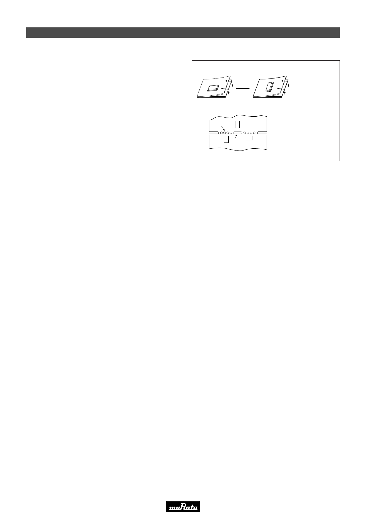
• This PDF catalog is downloaded from the website of Murata Manufacturing co., ltd. Therefore, it’s specifications are subject to change or our products in it may be discontinued without advance notice. Please check with our
!Note
• This PDF catalog has only typical specifications because there is no space for detailed specifications. Therefore, please approve our product specifications or transact the approval sheet for product specifications before ordering.
• Please read rating and !CAUTION (for storage, operating, rating, soldering, mounting and handling) in this catalog to prevent smoking and/or burning, etc.
!Note
sales representatives or product engineers before ordering.
• This catalog has only typical specifications because there is no space for detailed specifications. Therefore, please approve our product specifications or transact the approval sheet for product specifications before ordering.
Notice (Handling)
■ Ceramic Discriminator 10.7MHz Chip Type
1. The component mounted on the PCB may be damaged if
excessive mechanical stress is applied.
2. Layout the components on the PCB to minimize the
stress imposed on the warp or flexure of the board.
3. After installing components, if solder is excessively
applied to the circuit board, mechanical stress will cause
destruction resistance characteristics to lower. To prevent
this, be extremely careful in determining shape and
dimension before designing the circuit board diagram.
4. The component may be damaged during mounting
process if some part of mounter such as positioning
claws or nozzle are worn down. The regular maintenance
recommended for mounters should be done to prevent
troubles.
5. When correcting component's position with a soldering
iron, the tip of the soldering iron should not directly touch
the chip component. Depending on the soldering
conditions, the effective area of terminations may be
reduced. The use of solder containing Ag should be
considered to prevent the electrode erosion.
6. Do not clean or wash the component as it is not
hermetically sealed.
7. In case of overcoating the part, coating conditions such
as material of resin, curing temperature, and so on
should be evaluated carefully.
8. Accurate test circuit values are required to measure
electrical characteristics.
It may be a cause of miscorrelation if there is any
deviation, especially stray capacitance, from the test
circuit in the specification.
9. For safety purposes, avoid applying a direct current
between the terminals.
[Component Direction]
[Component Layout Close to Board]
Perforation
B
A
C
Slit
Susceptibility to
stress is in the order
of : A>C>B
P50E.pdf
10.2.9
Put the
component
laterally to the
direction in
which stress
acts.
19
■ Ceramic Discriminator 10.7MHz Lead Type
1. Do not use this product with bend. The component
may be damaged if excess mechanical stress is
applied to it mounted on the printed circuit board.
2. The component may be damaged when an excessive
stress is applied.
3. All kinds of re-flow soldering must not be applied
on the component.
4. Do not clean or wash the component as it is not
hermetically sealed.
5. Do not use strong acidity flux, more than 0.2wt%
chlorine content, in flow soldering.
6. In case of covering discriminator with over coat,
conditions such as material of resin, cure
temperature, and so on should be evaluated
carefully.
7. Accurate test circuit values are required to
measure electrical characteristics. It may be a
cause of miscorrelation if there is any deviation,
especially stray capacitance, from the test
circuit in the specification.
8. For safety purposes, avoid applying a direct
current between the terminals.
78
Page 81
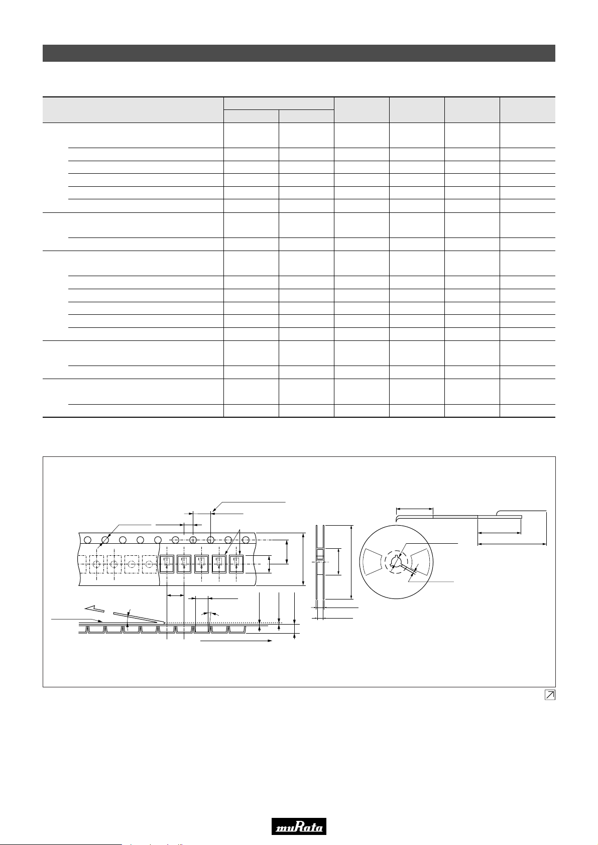
• This PDF catalog is downloaded from the website of Murata Manufacturing co., ltd. Therefore, it’s specifications are subject to change or our products in it may be discontinued without advance notice. Please check with our
!Note
• This PDF catalog has only typical specifications because there is no space for detailed specifications. Therefore, please approve our product specifications or transact the approval sheet for product specifications before ordering.
• Please read rating and !CAUTION (for storage, operating, rating, soldering, mounting and handling) in this catalog to prevent smoking and/or burning, etc.
!Note
sales representatives or product engineers before ordering.
• This catalog has only typical specifications because there is no space for detailed specifications. Therefore, please approve our product specifications or transact the approval sheet for product specifications before ordering.
Packaging
■ Minimum Quantity
Taping
ø180mmø330mm
CERAFILr<10.7MHz>
2,000
2,000
2,000
1,500
1,500
1,500
1,000
1,500
500
500
500
500
500
200
500
50
50
50
50
CERAFILr<2.3-6.5MHz>
CERAFILr<455kHz>
Ceramic Traps<3.5-6.5MHz>
Ceramic Discriminators<10.7MHz>
SFECF
SFECV/SFECK
SFELF
SFELG
SFKLF
SFVLF
SFSKA
SFSKB
CFULA
CFWLA
SFPKA
SFPLA
SFULA
SFZLA
TPSKA
TPWKA
CDALF
CDSCB
3,000
3,000
1,000
3,000
3,000
P50E.pdf
10.2.9
BoxMagazineBulkAmmo Pack
200
150
200
■ CERAFILr 10.7MHz Chip Type SFECF Series
Dimensions of Carrier Tape Dimensions of Reel
10 pitch accumulated
4.0±0.1
ø1.55±0.05
Peeling strength
(0.1 to 0.7N)
Cover film
• Part number marked side is always facing upside.
• The feeding holes side of cavity tape is always input terminal.
10˚ max.
2.0±0.05
4.0±0.1
Chip filter
+0.1
3.35
-0.05
3˚ max.
User direction of feed
40±0.15
4.1±0.1
0.3±0.05
Trailer Leader
160 to 190
Components
Empty
ø13.0±0.5
-1.5
+0
-0
5.5±0.05
12.0±0.2
(0.05)
1.84±0.1
+1.0
60
17.0±1.0
+1.0
13.0
-0
180
2.0±0.5
Continued on the following page.
Empty
240 to 280
400 to 560
( ) : Reference
Cover film
(in mm)
79
19
Page 82
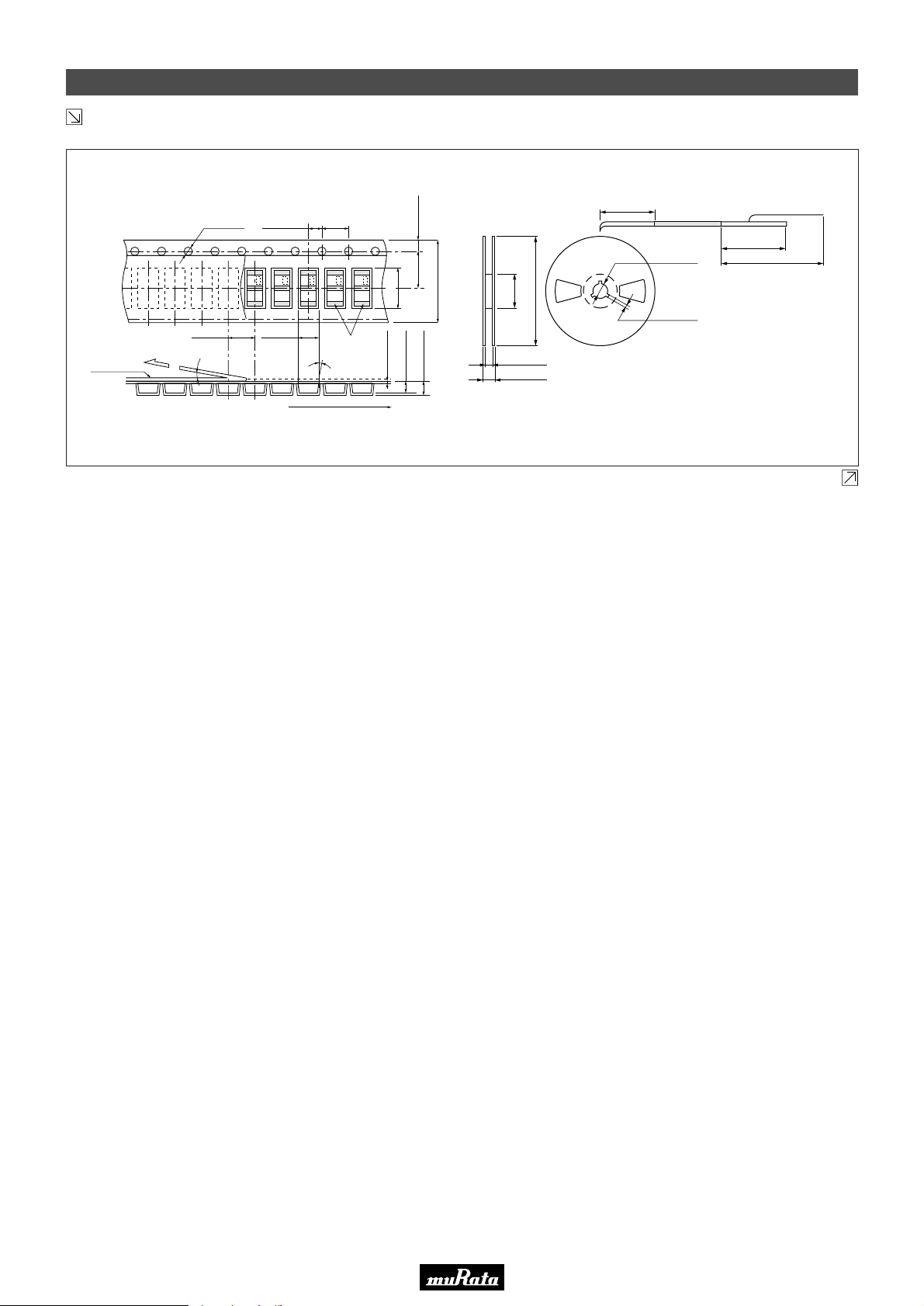
• This PDF catalog is downloaded from the website of Murata Manufacturing co., ltd. Therefore, it’s specifications are subject to change or our products in it may be discontinued without advance notice. Please check with our
!Note
• This PDF catalog has only typical specifications because there is no space for detailed specifications. Therefore, please approve our product specifications or transact the approval sheet for product specifications before ordering.
• Please read rating and !CAUTION (for storage, operating, rating, soldering, mounting and handling) in this catalog to prevent smoking and/or burning, etc.
!Note
sales representatives or product engineers before ordering.
• This catalog has only typical specifications because there is no space for detailed specifications. Therefore, please approve our product specifications or transact the approval sheet for product specifications before ordering.
Packaging
Continued from the preceding page.
■ CERAFILr 10.7MHz Chip Type SFECV/SFECK Series
P50E.pdf
10.2.9
Dimensions of carrier tape
W0.1
2.0T0.05 4.0T0.1
Y0.0
ø1.5
∗∗∗∗∗∗∗∗∗∗∗∗∗
3.0T0.14.0T0.1
Peeling strengh 0.1 to 0.7N
Cover film
• Part number marked side is always facing up.
• The feeding holes side of cavity tape is always input terminal.
10° max.
Chip filter
3° max.
User direction of feed
Dimension of reel
Trailer Leader
160-190
Components
1.75T0.1
∗∗
5.5T0.05
12.0T0.2
7.3T0.01
W0.1
Y0.05
1.9T0.1
1.7
0.3T0.05
+0
+1.0
-0
60
13.0
17.0±1.0
-1.5
180
+1.0
-0
Empty
ø13.0±0.5
2.0±0.5
Continued on the following page.
Cover film
Empty
240-280
400-560
( ) : Reference
(in mm)
19
80
Page 83
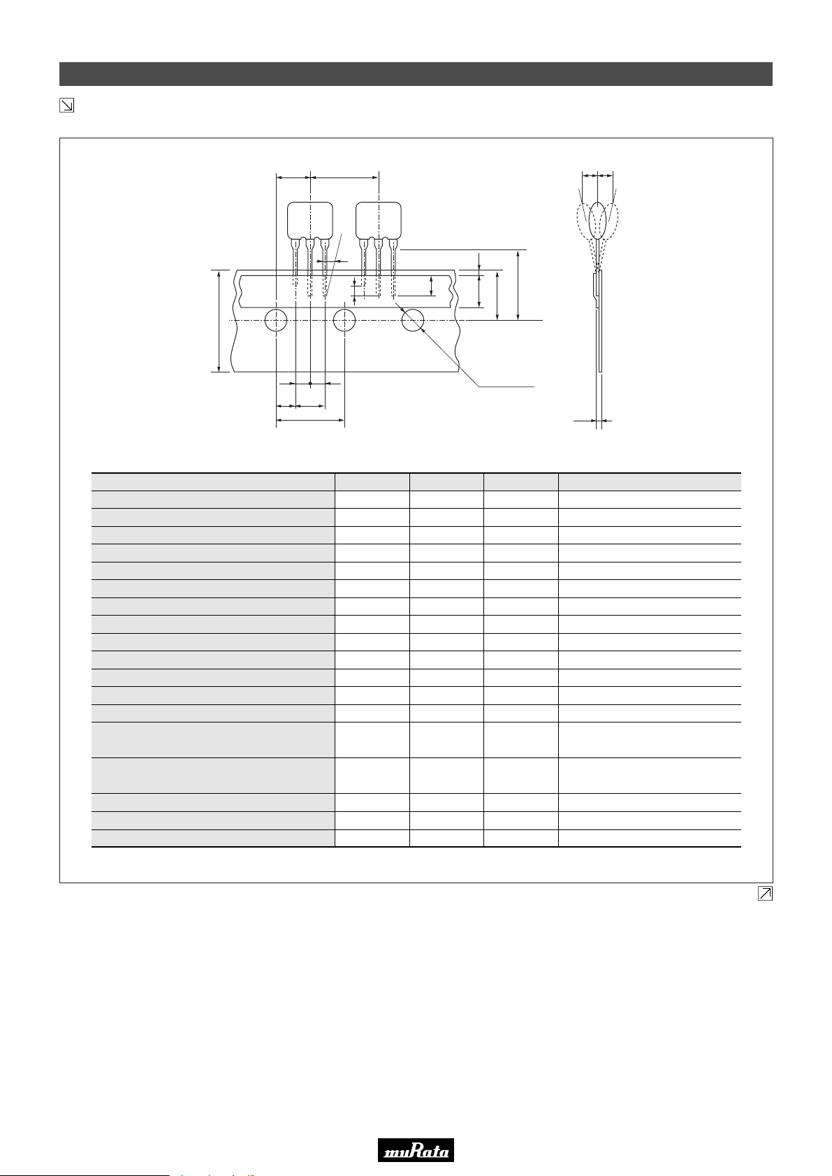
• This PDF catalog is downloaded from the website of Murata Manufacturing co., ltd. Therefore, it’s specifications are subject to change or our products in it may be discontinued without advance notice. Please check with our
!Note
• This PDF catalog has only typical specifications because there is no space for detailed specifications. Therefore, please approve our product specifications or transact the approval sheet for product specifications before ordering.
• Please read rating and !CAUTION (for storage, operating, rating, soldering, mounting and handling) in this catalog to prevent smoking and/or burning, etc.
!Note
sales representatives or product engineers before ordering.
• This catalog has only typical specifications because there is no space for detailed specifications. Therefore, please approve our product specifications or transact the approval sheet for product specifications before ordering.
Packaging
Continued from the preceding page.
■ CERAFILr 10.7MHz Lead Type SF_LF Series
P50E.pdf
10.2.9
P2 P
W
F
1
P
Item Code Dimensions Tolerance Remarks
Lead length under the hold down tape
Length of cut off
Pitch of components
Pitch of sprocket hole (1)
Length from hole center to lead
Length from hole center to component center
Lead spacing (1)
Lead spacing (2)
Slant to the forward or backward
Slant to the left or right
Width of carrier tape
Width of hold down tape
Position of sprocket hole
Gap of hold down tape and carrier tape
Distance between the center of sprocket
hole and lead stopper
Diameter of sprocket hole
Total tape thickness
Pitch of sprocket hole (2)
1 F1
F
P0
dh dh
1
dS
W2
1
L2
L
1
L2
P
P
0
P1
P2
F
F
1
dh
dS
1
W
W
0
W1
W2
H0
D0
t
P
020
L
3.0 min.
2.0 max.
12.7
12.7
3.85
6.35
5.0
2.5
0
0
18.0
6.0 min.
9.0
0
18.0
ø4.0
0.6
254.0
H0
W0
W1
D0
t
-
-
To distinguish the direction
±0.5
±0.2
±0.5
±0.5
+0.5
–0.2
±0.2
±1.0
±1.0
±0.5
-
±0.5
+0.5
–0
Hold down tape doesn't exceed
the carrier tape
±0.5
±0.2
±0.2
±1.5
The pitch of 20 sprocket holes
(in mm)
Continued on the following page.
19
81
Page 84
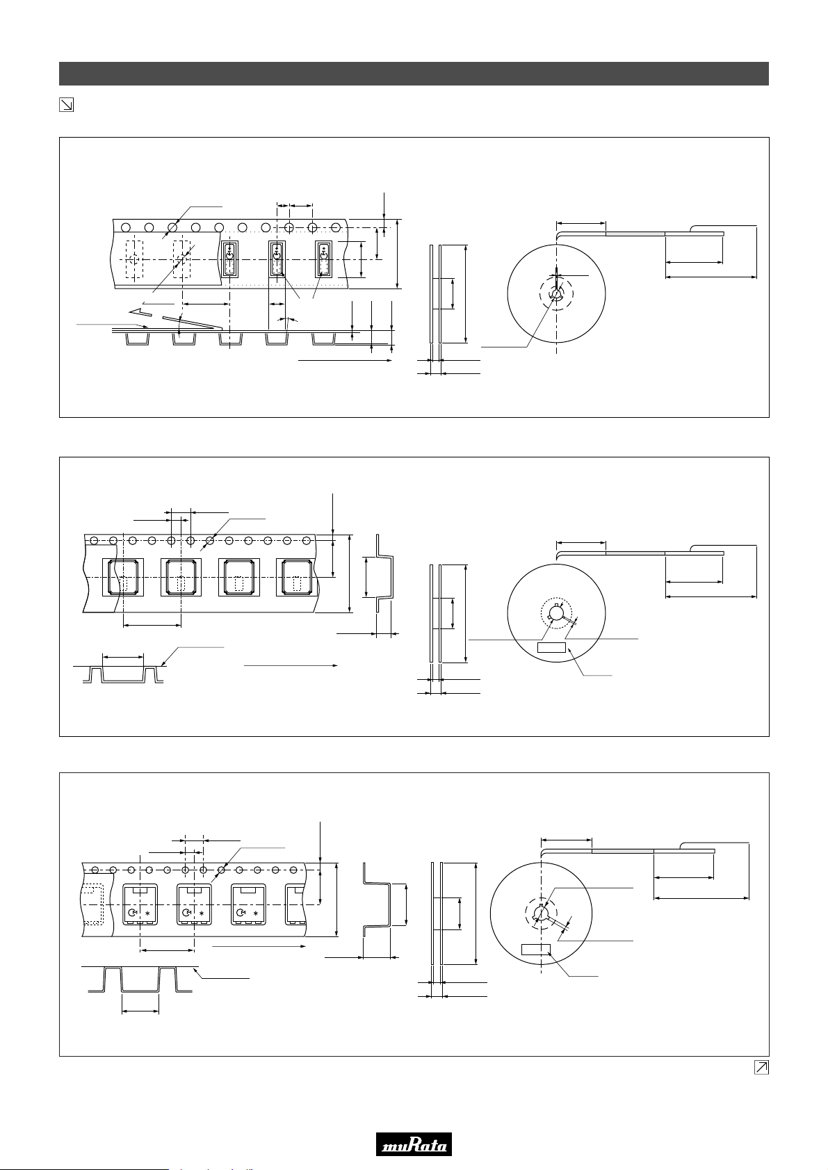
∗
• This PDF catalog is downloaded from the website of Murata Manufacturing co., ltd. Therefore, it’s specifications are subject to change or our products in it may be discontinued without advance notice. Please check with our
!Note
• This PDF catalog has only typical specifications because there is no space for detailed specifications. Therefore, please approve our product specifications or transact the approval sheet for product specifications before ordering.
• Please read rating and !CAUTION (for storage, operating, rating, soldering, mounting and handling) in this catalog to prevent smoking and/or burning, etc.
!Note
sales representatives or product engineers before ordering.
• This catalog has only typical specifications because there is no space for detailed specifications. Therefore, please approve our product specifications or transact the approval sheet for product specifications before ordering.
Packaging
Continued from the preceding page.
■ CERAFILr 4.5-6.5MHz Chip Type SFSKA Series
P50E.pdf
10.2.9
Dimensions of Carrier Tape
+0.1
ø1.5
–0.0
Peeling strength
(0.1 to 0.7N)
Cover film
• Part number marked side is always facing upside.
• The feeding holes side of cavity tape is always input terminal.
ø1.5
+0.1
–0.0
8.0±0.1
10˚ max.
2.0±0.1 4.0±0.1
4.3±0.1
Chip filter
3˚ max.
User direction of feed
9.0±0.1
+0.1
–0.05
2.1
0.3±0.05
■ CERAFILr 2.3-5.7MHz Chip Type SFSKB Series
2.0±0.1
∗ ∗ ∗
4.0±0.1
ø1.5
+0.1
–0.0
1.75±0.1
5.5±0.1
5.6±0.1
12.0±0.2
Dimensions of Reel
1.75±0.1
7.5±0.1
16.0±0.2
80±1
330±2
2.3±0.1
ø13.0±0.2
17.5±1.5
21.5±1.0
Trailer
160 to 190
2.2±0.5
ComponentsEmpty
Leader
Cover film
Empty
240 to 280 min.
400 to 560
(in mm)
Dimensions of ReelDimensions of Carrier Tape
Trailer
160 to 190
ComponentsEmpty
Leader
Cover Film
Empty
240 to 280
400 to 560
8.0±0.1
4.2±0.1
• Part Number marked side is always facing upside.
• The direction of electrode shall be placed by one direction.
Cover Film
User direction of feed
1.6±0.1
■ CERAFILr 455kHz Chip Type SFPKA Series
Dimensions of Carrier Tape
7.4±0.1
2.0±0.1
12.0±0.1
4.0±0.1
User direction of feed
Cover film
+0.1
ø1.5
-0
7.5±0.1 1.75±0.1
16.0±0.2
5.3±0.1
• Part number marked side is always facing upside.
• The feeding holes side of cavity tape is always input terminal.
(ø80)
(ø330)
13.5±1.0
17.5±1.5
ø13.0±0.2
2.2±0.2
Label
(in mm)
Dimensions of Reel
Trailer Leader
160 to 190
Empty
ø13.0±0.2
8.8±0.1
80±1
330±2
17.5±0.5
21.5±1.0
2.2±0.5
Label
Cover film
EmptyComponents
240 to 280
400 to 560
(in mm)
19
Continued on the following page.
82
Page 85
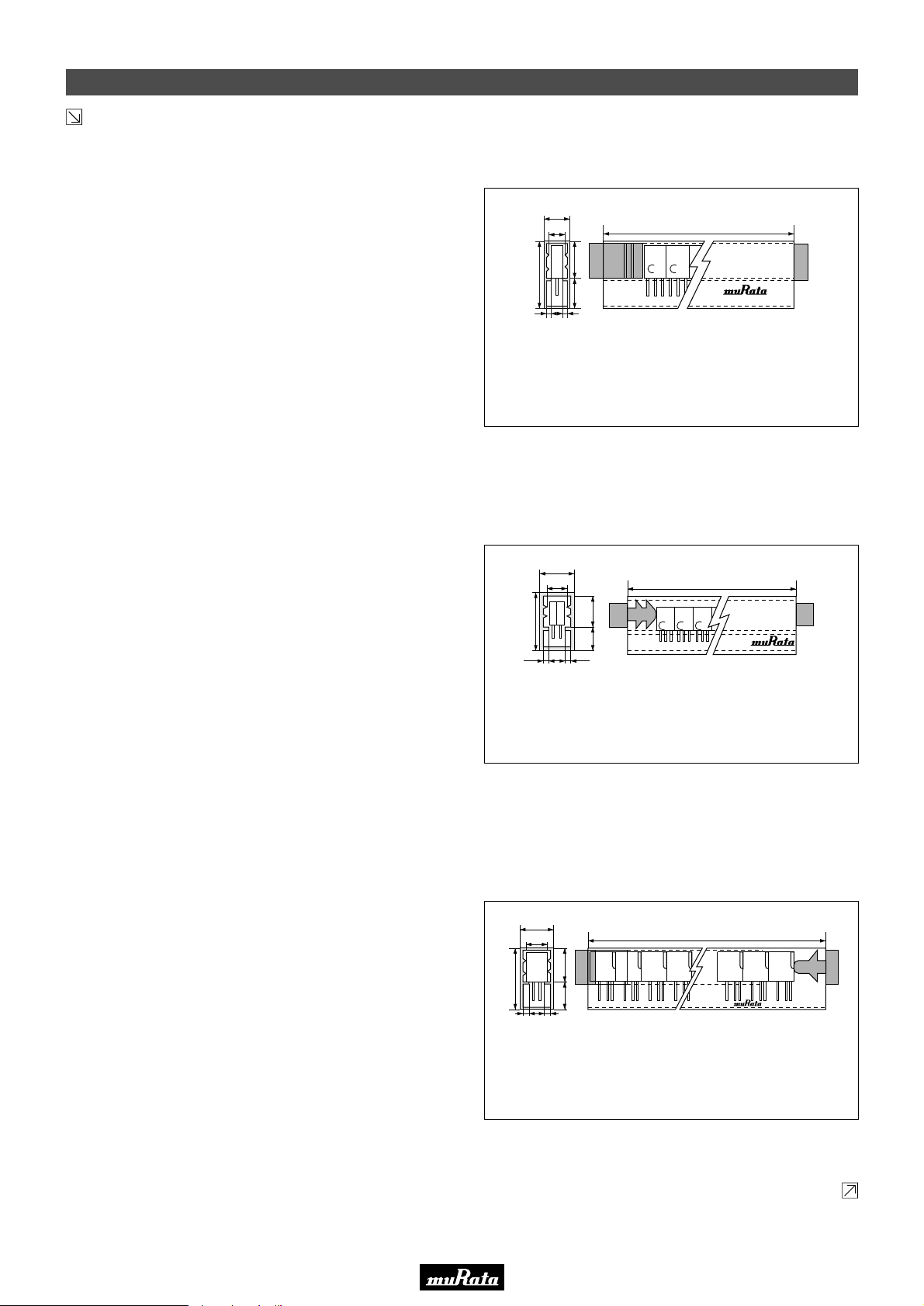
• This PDF catalog is downloaded from the website of Murata Manufacturing co., ltd. Therefore, it’s specifications are subject to change or our products in it may be discontinued without advance notice. Please check with our
!Note
• This PDF catalog has only typical specifications because there is no space for detailed specifications. Therefore, please approve our product specifications or transact the approval sheet for product specifications before ordering.
• Please read rating and !CAUTION (for storage, operating, rating, soldering, mounting and handling) in this catalog to prevent smoking and/or burning, etc.
!Note
sales representatives or product engineers before ordering.
• This catalog has only typical specifications because there is no space for detailed specifications. Therefore, please approve our product specifications or transact the approval sheet for product specifications before ordering.
Packaging
Continued from the preceding page.
■ CERAFILr 455kHz Lead Type SFULA Series
Standard of Magazine Cassette
1. Putting CERAFILr into Magazine
A magazine should contain 50pcs of CERAFILr, with the
marking of products all facing toward the "Murata" mark
on a magazine, and be closed with exclusive stoppers at
both ends. Above should be the minimum packaging unit.
2. Quality of Magazine
(1) Transparent so that input / output direction is visually
recognizable.
(2) With an angle of 35° CERAFILr should slip down
smoothly.
(3) Antistatic finish
(4) Recycling
Note: Magazines should be sent back for recycling.
(Therefore, empty magazines should not be damaged.)
3. Dimensions of Magazine Cassette
5.6±0.3
4.2±0.25
10±0.38.1±0.3
18.7±0.3
1.1 1.1
Material: Polycarbonate
Camber of Case: ±1mm max. against entire length (reference)
Twist of Case: ±0.5mm max. (reference)
+0
390
–2
*M*
M
Tolerance unless otherwise specified: ±0.2
P50E.pdf
10.2.9
(in mm)
■ CERAFILr 455kHz Lead Type SFZLA Series
Standard of Magazine Cassette
1. Putting CERAFILr into Magazine
A magazine should contain 50pcs of CERAFILr, with the
marking of products all facing toward the "Murata" mark
on a magazine, and be closed with exclusive stoppers at
both ends. Above should be the minimum packaging unit.
2. Quality of Magazine
(1) Transparent so that input / output direction is visually
recognizable.
(2) With an angle of 35° CERAFILr should slip down
smoothly.
(3) Antistatic finish
(4) Recycling
Note: Magazines should be sent back for recycling.
(Therefore, empty magazines should not be damaged.)
■ CERAFILr 455kHz Lead Type SFPLA Series
Standard of Magazine Cassette
1. Putting CERAFILr into Magazine
A magazine should contain 50pcs of CERAFILr, which
ground terminals are all facing toward the "Murata" mark
on a magazine, and be closed with exclusive stoppers at
both ends. Above should be the minimum packaging unit.
2. Quality of Magazine
(1) Transparent so that input / output direction is visually
recognizable.
(2) With an angle of 35° CERAFILr should slip down
smoothly.
(3) Antistatic finish
(4) Recycling
Note: Magazines should be sent back for recycling.
(Therefore, empty magazines should not be damaged.)
3. Dimensions of Magazine Cassette
9.0±0.3
7.6±0.25
18.7±0.3
1.1
Material: Polycarbonate
Camber of Case: ±1mm max. against entire length (reference)
Twist of Case: ±0.5mm max. (reference)
10.0±0.3
8.1±0.3
1.1
+0
390
–2
*M*M*
M
Tolerance unless otherwise specified: ±0.2
3. Dimensions of Magazine Cassette
9.0±0.3
7.6±0.25
10±0.38.1±0.3
18.7±0.3
1.1 1.1
Material: Polycarbonate
Camber of Case: ±1mm max. against entire length (reference)
Twist of Case: ±0.5mm max. (reference)
405±1.0
Tolerance unless otherwise specified: ±0.2
Continued on the following page.
(in mm)
HP51M0003-02
(in mm)
83
19
Page 86
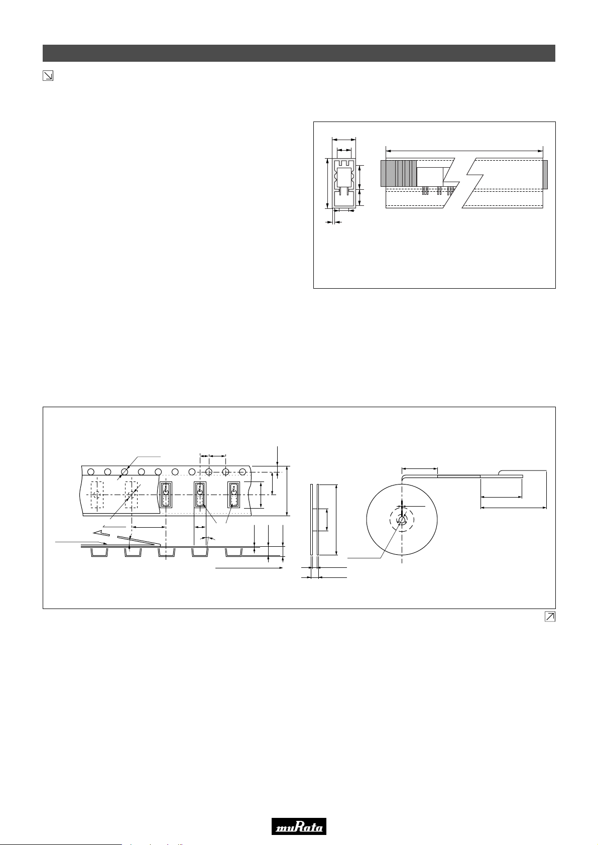
• This PDF catalog is downloaded from the website of Murata Manufacturing co., ltd. Therefore, it’s specifications are subject to change or our products in it may be discontinued without advance notice. Please check with our
!Note
• This PDF catalog has only typical specifications because there is no space for detailed specifications. Therefore, please approve our product specifications or transact the approval sheet for product specifications before ordering.
• Please read rating and !CAUTION (for storage, operating, rating, soldering, mounting and handling) in this catalog to prevent smoking and/or burning, etc.
!Note
sales representatives or product engineers before ordering.
• This catalog has only typical specifications because there is no space for detailed specifications. Therefore, please approve our product specifications or transact the approval sheet for product specifications before ordering.
Packaging
Continued from the preceding page.
■ CERAFILr 455kHz Lead Type CFWLA Series
Standard of Magazine Cassette
1. Putting CERAFILr into Magazine
A magazine should contain 50pcs of CERAFILr, with
ground terminals all facing toward the "Murata" mark on a
magazine, and be closed with exclusive stoppers at both
ends. Above should be the minimum packaging unit.
2. Quality of Magazine
(1) Transparent so that input / output direction is visually
recognizable.
(2) With an angle of 35° CERAFILr should slip down
smoothly.
(3) Antistatic finish
(4) Recycling
Note: Magazines should be sent back for recycling.
(Therefore, empty magazines should not be damaged.)
4. Dimensions of Magazine Cassette
9.0±0.3
7.3±0.25
18.7±0.3
5.3±0.3
0.6
Material: Polycarbonate
Camber of Case: ±1mm max. against entire length (reference)
Twist of Case: ±0.5mm max. (reference)
9.0±0.3
7.5±0.3
576.0±2.0
Tolerance unless otherwise specified: ±0.2
P50E.pdf
10.2.9
ANTISTATIC
muRataHP51M0064
(in mm)
3. Magazine should be packaged in a cardboard box.
MURATA model name, quantity and outgoing inspection
number should be indicated on the box.
Cardboard box may contain maximum 33 magazines
(1,650 pieces of filter).
■ Ceramic Trap 4.5-6.5MHz Chip Type TPSKA Series
Dimensions of Carrier Tape
+0.1
ø1.5
–0.0
Peeling strength
(0.1 to 0.7N)
Cover film
• Part number marked side is always facing upside.
• The feeding holes side of cavity tape is always input terminal.
ø1.5
+0.1
–0.0
8.0±0.1
10˚ max.
2.0±0.1 4.0±0.1
4.3±0.1
Chip filter
3˚ max.
User direction of feed
1.75±0.1
7.5±0.1
9.0±0.1
+0.1
–0.05
2.3±0.1
2.1
0.3±0.05
Dimensions of Reel
Trailer
160 to 190
ComponentsEmpty
16.0±0.2
80±1
330±2
ø13.0±0.2
17.5±1.5
21.5±1.0
2.2±0.5
Leader
Cover film
Empty
240 to 280 min.
400 to 560
(in mm)
19
Continued on the following page.
84
Page 87
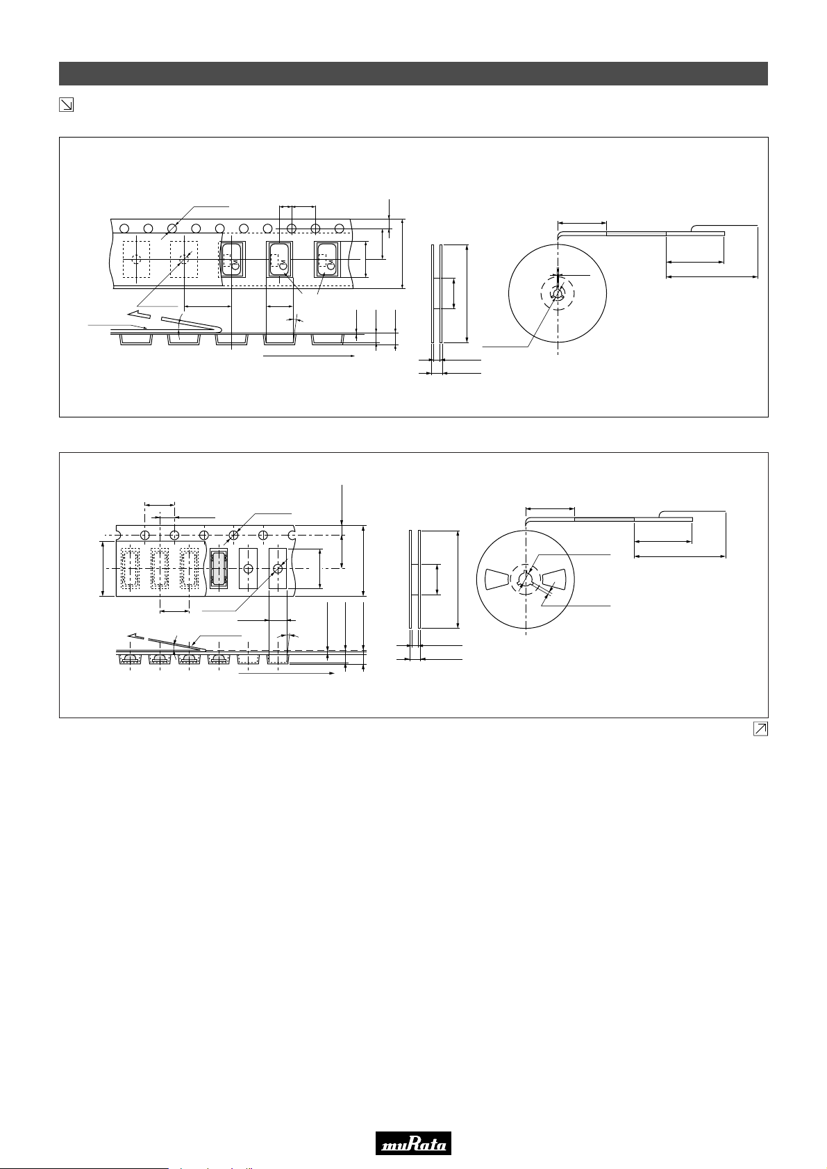
• This PDF catalog is downloaded from the website of Murata Manufacturing co., ltd. Therefore, it’s specifications are subject to change or our products in it may be discontinued without advance notice. Please check with our
!Note
• This PDF catalog has only typical specifications because there is no space for detailed specifications. Therefore, please approve our product specifications or transact the approval sheet for product specifications before ordering.
• Please read rating and !CAUTION (for storage, operating, rating, soldering, mounting and handling) in this catalog to prevent smoking and/or burning, etc.
!Note
sales representatives or product engineers before ordering.
• This catalog has only typical specifications because there is no space for detailed specifications. Therefore, please approve our product specifications or transact the approval sheet for product specifications before ordering.
Packaging
Continued from the preceding page.
■ Ceramic Trap 4.5-6.5MHz Chip Type TPWKA Series
P50E.pdf
10.2.9
Dimensions of carrier tape
+0.1
ø1.5
–0.0
Peeling strength
(0.1 to 0.7N)
Cover film
• Part number marked side is always facing up.
ø1.5
+0.1
–0.0
10˚ max.
2.0±0.1
∗
5.5±0.18.0±0.1
User direction of feed
4.0±0.1
∗
Chip filter
3˚ max.
1.75±0.1
∗
7.5±0.1
9.0±0.1
16.0±0.2
+0.1
–0.05
0.3±0.05
1.95±0.1
1.75
■ Ceramic Discriminator 10.7MHz Chip Type CDSCB Series
Dimensions of Carrier Tape
(9.0)
Peeling strength
0.1 to 0.7N
4.0±0.1
4.0±0.1
2.0±0.05
10˚
+0.1
ø1.5
-0
Cover film
2.2±0.1
ø1.5
+0.1
-0
3˚max.
1.75±0.1
5.5±0.05
4.7±0.1
12.0±0.2
1.1±0.1
0.3±0.05
(1.7 max.)
+0.1
13.0
17.0±1.0
-0
60
80±1
330±2
17.5±0.5
21.5±1.0
+0.1
-1.5
180
+1.0
-0
ø13.0±0.2
Dimensions of Reel
Trailer
160 to 190
ComponentsEmpty
240 to 280 min.
2.2±0.5
Dimension of reel
Trailer Leader
160 to 190
Empty
ø13.0±0.2
2.0±0.5
Cover film
EmptyComponents
240 to 280
400 to 560
Leader
Cover film
Empty
400 to 560
(in mm)
• Part number marked side is always facing upside.
User direction of feed
• The feeding holes side of cavity tape is always input terminal.
( ) : Reference
(in mm)
Continued on the following page.
85
19
Page 88
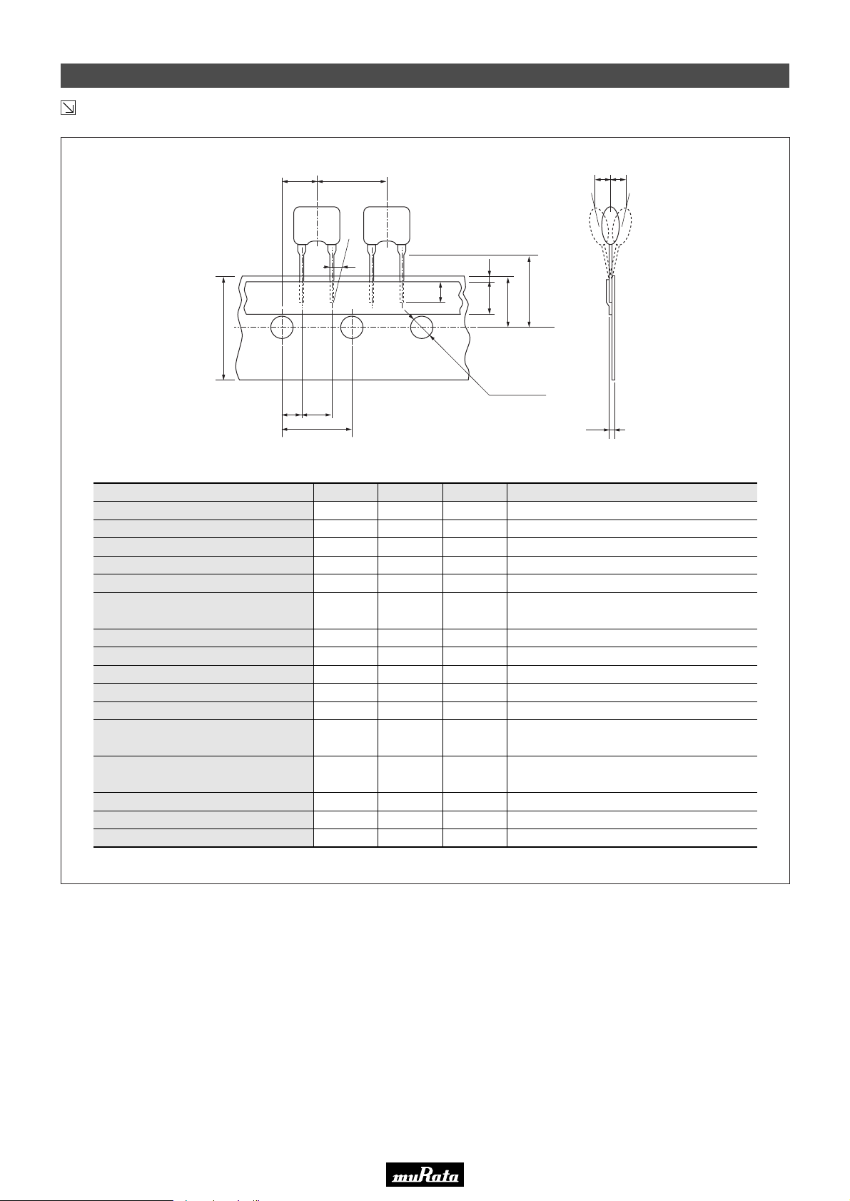
• This PDF catalog is downloaded from the website of Murata Manufacturing co., ltd. Therefore, it’s specifications are subject to change or our products in it may be discontinued without advance notice. Please check with our
!Note
• This PDF catalog has only typical specifications because there is no space for detailed specifications. Therefore, please approve our product specifications or transact the approval sheet for product specifications before ordering.
• Please read rating and !CAUTION (for storage, operating, rating, soldering, mounting and handling) in this catalog to prevent smoking and/or burning, etc.
!Note
sales representatives or product engineers before ordering.
• This catalog has only typical specifications because there is no space for detailed specifications. Therefore, please approve our product specifications or transact the approval sheet for product specifications before ordering.
Packaging
Continued from the preceding page.
■ Ceramic Discriminator 10.7MHz Lead Type CDALF Series
P50E.pdf
10.2.9
W
P
Item Code Dimensions Tolerance Remarks
Lead length under the hold down tape
Pitch of component
Pitch of sprocket hole (1)
Length from hole center to lead
Length from hole center to component center
Lead spacing
Slant to the forward or backward
Slant to the left or right
Width of carrier tape
Width of hold down tape
Position of sprocket hole
Gap of hold down tape and
carrier tape
Distance between the center of
sprocket hole and lead stopper
Diameter of sprocket hole
Total tape thickness
Pitch of sprocket hole (2)
P2 P
1
F
P0
dS
Po20
L
P
P
P1
P2
dh
W
W
W1
W2
H0
D0
dh dh
1
dS
W2
1
L
1
3.0 min.
12.7
0
12.7
3.85
6.35
F
5.0
0
1
0
18.0
6.0 min.
0
9.0
0
18.0
ø4.0
t
0.6
254.0
-
±0.5
±0.2
±0.5
±0.5
+0.5
-0.2
±1.0
±1.0
±0.5
-
±0.5
+0.5
-0.0
±0.5
±0.2
±0.2
±1.5
H0
W0
W1
D0
t
Hold down tape doesn't exceed the carrier tape
The pitch of 20 sprocket holes
19
(in mm)
86
Page 89
Part Number Index
!Note
• Please read rating and !CAUTION (for storage, operating, rating, soldering, mounting and handling) in this catalog to prevent smoking and/or burning, etc.
• This catalog has only typical specifications because there is no space for detailed specifications. Therefore, please approve our product specifications or transact the approval sheet for product specifications before ordering.
• This PDF catalog is downloaded from the website of Murata Manufacturing co., ltd. Therefore, it’s specifications are subject to change or our products in it may be discontinued without advance notice. Please check with our
!Note
sales representatives or product engineers before ordering.
• This PDF catalog has only typical specifications because there is no space for detailed specifications. Therefore, please approve our product specifications or transact the approval sheet for product specifications before ordering.
P50E.pdf
10.2.9
CDALF
CDSCB
CFULA
CFWLA
SFECF
SFECK
SFECV
SFELF
SFELG
SFKLF
SFPKA
SFPLA
SFSKA
SFSKB
SFULA
SFVLF
SFZLA
TPSKA
TPWKA
··········
··········
··········
··········
··········
··········
··········
··········
··········
··········
··········
··········
··········
··········
··········
··········
··········
··········
··········
Ceramic Discriminators for FM
Chip Ceramic Discriminators for FM
Ceramic Filters (CERAFILr) for AM
Ceramic Filters (CERAFILr) for AM
Chip Ceramic Filters (CERAFILr) for FM
Chip Ceramic Filters (CERAFILr) for FM
Chip Ceramic Filters (CERAFILr) for FM
Ceramic Filters (CERAFILr) for FM
Ceramic Filters (CERAFILr) for FM
Ceramic Filters (CERAFILr) for FM
Chip Ceramic Filters (CERAFILr) for AM
Ceramic Filters (CERAFILr) for AM
··············································
··········································
··········································
·······································
····································
·····································
·····································
·····················
·······································
··········································
·····································
·······································
Chip Ceramic Filters (CERAFILr) for TV/VCR
Chip Ceramic Filters (CERAFILr) for TV/VCR
Ceramic Filters (CERAFILr) for AM
Ceramic Filters (CERAFILr) for FM
Ceramic Filters (CERAFILr) for AM
Chip Ceramic Traps
·······················································
Chip Ceramic Traps (Double Traps)
··········································
··········································
··········································
··········································
p48, 50
p14, 17, 23-24, 26, 28-29, 31
p20-21
p48, 50
·································
·································
p62
p57
p50
p5-6
p11
p11
p28
p43
p35
p38
p45
p28
p45
p54
p56
87
Page 90
• This PDF catalog is downloaded from the website of Murata Manufacturing co., ltd. Therefore, it’s specifications are subject to change or our products in it may be discontinued without advance notice. Please check with our
!Note
sales representatives or product engineers before ordering.
• This PDF catalog has only typical specifications because there is no space for detailed specifications. Therefore, please approve our product specifications or transact the approval sheet for product specifications before ordering.
P50E.pdf
10.2.9
 Loading...