

Page 1
Manual & Service Guide
RPR750 Series Paging Receiver
TM1215 (Issue 6.0)
Time critical messaging
Page 2

TM1215 Iss. 6.0 RPR750
Issue Control
Issue Date Remarks
6.0
15.03.10
First Issue of re-formatted document, including MKII
Decoder PCB and revised case-style data.
i
Page 3

TM1215 Iss. 6.0 RPR750
Contents
Company Liability ...................................................................................................................... 1
Safety summary ......................................................................................................................... 2
Compliance Statements & WEE Information.............................................................................. 3
1. Introduction................................................................................................................................. 4
1.1 Features ......................................................................................................................... 4
1.2 Technical Specification................................................................................................... 6
2. User Operating Instructions ....................................................................................................... 9
2.1 Introduction..................................................................................................................... 9
2.2 Controls & Indicators ......................................................................................................9
2.3 Wearing the Pager ....................................................................................................... 10
2.4 Operation of the Pager ................................................................................................. 10
2.5 Options & Features ...................................................................................................... 16
3. Technical Description............................................................................................................... 22
3.1 Physical Construction................................................................................................... 22
3.2 Functional Description.................................................................................................. 23
4. Servicing .................................................................................................................................. 28
4.1 Routine Maintenance ................................................................................................... 28
4.2 Service Policy............................................................................................................... 28
4.3 Test Equipment & Tools ............................................................................................... 28
4.4 Dismantling the Pager .................................................................................................. 29
4.5 Servicing Information for Decoder PCB's ..................................................................... 33
4.6 Alignment of VHF & UHF Radio PCB's ........................................................................ 38
4.7 Alignment of HF Radio PCB......................................................................................... 40
5. List of Diagrams & Drawings.................................................................................................... 42
ii
Page 4

TM1215 Iss. 6.0 RPR750
Company Liability
The contents of this manual have been checked and verified for technical accuracy.
Multitone Electronics plc accepts no liability for inaccuracies, or errors. In accordance with
the company policy of continuous product development, the content of this manual may
be altered. The user of this document should ensure that they are in possession of the
correct issue of this document, before attempting any work on equipment.
Multitone Electronics plc
Multitone House,
Shortwood Copse Lane,
Kempshott,
Basingstoke,
Hampshire,
England
RG23 7NL
1
Page 5
TM1215 Iss. 6.0 RPR750
Safety Summary
The following information is applicable to both user and servicing personnel.
Warnings and cautions will be found throughout this document, where they are
deemed necessary.
Warning
statements identify conditions or practices, which could result in
injury, or loss of life.
Caution
statements identify conditions or practices, which could result in
damage to equipment.
WARNINGS
WHILST REFERENCE IS MADE IN THIS DOCUMENT TO THE INTRINSICALLY SAFE
(HAZARDOUS AREA) VARIANT OF THE RPR 750 SERIES, THIS MANUAL DOES
NOT COVER THE DETAILED SERVICING OF THIS PRODUCT VARIANT AND ANY
SUCH ITEMS SHOULD BE RETURNED TO MULTITONE FOR REPAIR.
DO NOT TAKE STANDARD VERSIONS OF THIS PAGER INTO AREAS
WHERE EXPLOSIVE MIXTURES MAY BE PRESENT
WHEN CHARGING IS ENABLED, ONLY PAGERS FITTED WITH
RECHARGEABLE BATTERIES SHOULD BE INSERTED INTO THE
ABSENCE/CHARGING RACKS, OR DESK-TOP CHARGERS
CAUTIONS
PROTECT THE PAGER FROM LIQUIDS, STRONG MAGNETIC FIELDS AND
EXTREME TEMPERATURES. DO NOT LEAVE THE PAGER EXPOSED TO STRONG
SUNLIGHT. AVOID SUCH AREAS AS CAR INTERIORS AND WINDOW LEDGES.
STATIC SENSITIVE DEVICES ARE USED IN THIS EQUIPMENT. CARE MUST BE
TAKEN, TO AVOID DAMAGE FROM HIGH LEVELS OF STATIC ELECTRICITY.
DO NOT PRESS ANY OF THE BUTTONS WHEN THE PAGER IS IN THE ABSENCE
RACK, OR PROGRAMMING POCKET.
2
Page 6

TM1215 Iss. 6.0 RPR750
Compliance Statements
EU Territories: - This product complies with the requirements of the EU Radio &
Telecommunications Terminal Equipment Directive 99/5/EC. A complete copy of the
associated Declaration Of Conformity for this and other Multitone products, may be
found at the following Multitone Internet address: - www.multitone.com/support
US/Canada: - This device complies with Part 15 of the FCC Rules and Industry
Canada standard RSS210. Operation is subject to the following two conditions:
(1), this device may not cause harmful interference and (2), this device must accept
any interference received, including interference that may cause undesired
operation.
Any unauthorised modification to this device may void the user's authority to
operate the equipment.
WEEE Directive & Product Disposal
At the end of its serviceable life, this product should not
be treated as household or general waste. It should be
handed over to the applicable collection point for the
recycling of electrical and electronic equipment, or
returned to Multitone or their agent, for disposal.
Any batteries associated with these products, must be
disposed of in accordance with local regulations for the
handling of such items, or returned to Multitone or our
agents, for disposal.
3
Page 7

TM1215 Iss. 6.0 RPR750
1. Introduction
The Multitone RPR 750 Series is a "top-fired" alphanumeric radio-paging receiver,
designed to operate in the 25 - 54MHz (751), 138 - 174MHz (752) and 407 - 470MHz
(753) radio frequency bands.
The paging and messaging data is transmitted, using either of the Multitone proprietary
MK6 and MK7 digital code formats, or the CCIR Radio Paging Code No.1 (POCSAG)
format. The Multitone formats also have the facility for enabling speech messages,
following initial paging data.
User alert facilities include selectable options of beep-alert tones, flashing LED, speech
and/or vibration. Any of these alert options may be accompanied by an alphanumeric
message, either pre-formatted up to 60 characters in length (Multitone MK6), or freeformatted up to 120 characters (Multitone MK7 and POCSAG).
For use in areas of classified hazardous atmospheres, the RPR 750 is also available in
"intrinsically safe" variants, which are certified to recognised international standards.
The equipment is powered from a single "AA" (LR6) size battery, or a "AAA" (LR03) for
the IS variant. This may be a disposable primary cell, or where the system is suitably
equipped, absence/charging racks enable the use of secondary re-chargeable cells.
During periods of battery replacement, or the pager being switched off, an internal backup storage device will enable the retention of data for up to 12 hours.
For the intrinsically safe equipment variants, only certain battery types are
permitted. Refer to user information for correct types, before attempting to replace
these items.
1.1 Equipment Features
The following operational features are available with the RPR 750 Series. The availability
of individual facilities, is dependent upon the equipment variant supplied, pre-programmed
options and User selected functions.
1.1.1 Code Formats:-
Multitone MK6, MK7 and CCIR Radio-paging Code No. 1 (RPC1) - POCSAG (512 & 1200
Baud).
1.1.3 Available Addresses: -
MK6 - a single address, plus one 10, 100 or 1,000 user group call option;
MK7 - up to 10 individual addresses, plus one 10, 100, 1,000, or 10,000 user group call
address and one all call address;
POCSAG - up to 4 individual address (RIC) codes, each with 4 function codes.
1.1.4 Alert options: -
• Audible alert level - ≥80dBA SPL @ 30cm, full volume.
• Beep alert - MK6/7 - up to 8 beep tone patterns; POCSAG - up to 8 cadence
patterns.
• Volume - user enabled volume control of beep & speech.
• Silent alert - user enabled option; vibrate and/or flashing red LED.
• Escalating alert - software enabled option; "Escalert" beep function, with 3 optional
start points, lamp only, quiet, or full.
• Alert duration - software enabled option; 8s, 16s, 32s, or continuous.
4
Page 8

TM1215 Iss. 6.0 RPR750
• Extended alert - software enabled option; flashing LED every 2s, programmable
tone & vibrate repeat period, 2s to 512s; alert continues until cancelled by user.
1.1.5 Display: -
14 character Liquid Crystal Display (LCD), with full alphanumeric scrolling
capability. User selectable read orientation; automatic white LED back-lighting;
software enabled "on demand" option.
1.1.6 Message options: -
• Free format - Maximum off-air message length per call of 120 characters;
maximum of 5 stored message calls, or total of 600 characters; each message
time stamped.
• Beep code alpha format - up to 4 pre-programmed alphanumeric messages, each
of up to 14 characters in length.
1.1.7 Speech (MK6 & MK7 variants only)
• "Live" and stored speech message options. Auto-switched to live speech with pre-
set timeouts (10s, 30s or 150s); termination off-air by encoder, or locally by
CANCEL button.
• Up to 120s of speech storage available, configurable in 5 partitions of 24s duration
per partition.
1.1.8 Optional Features
• Language - software enabled option; English, French, German, Dutch, plus 12
further options.
• Call Comparator - software enabled option; will ignore any call identified as a
"repeat" of the previous call, within chosen time period of 30s, 120s or 300s.
• Time display - software enabled option; on or off. May be set within the pager, or
received as an off-air signal from the controlling system.
• Out of range warning - software enabled option; alert to be given after a period of
3.5 minutes (MK6/MK7), or 5 minutes (POCSAG). Audible, tactile and visual alert
options.
• Low battery indication - software enabled option; audible, tactile and visual alert
options (not recommended for re-chargeable cells).
• Permanent On - software enabled option.
• Test mode - software enabled option; will override programmed alert options to
provide a short alert + call-count function for test purposes (coverage or pager).
1.1.9 Mechanical Construction
• Minimum IP54 rated ingress protection.
• Detachable Griptite clip.
• Optional detachable lanyard.
1.1.10 Charging/Absence/Programming
Contacts are provided to enable charging, absence registration and programming
facilities.
• Charging - options of charging rack, absence/charging rack, or single desk-top
charging unit. For Intrinsically safe variants, only protected charging units as
supplied by Multitone should be used.
• Absence - automatic absence registration when inserted into an absence rack.
Data link with control system provides message facility e.g. display User No. Pager
automatically enters switch-on sequence, when removed from the rack.
• Programming - software enabled options, may be programmed using a Multitone
programming "pocket", software and a PC.
5
Page 9

TM1215 Iss. 6.0 RPR750
1.2. Technical Specifications
1.2.1 Radio Parameters
Model: UHF - RPR753; VHF - RPR752; HF - RPR751
Frequency Range:
407 - 470MHz 137 - 174MHz 25 - 54MHz
Frequency Bands:
407 - 417MHz 137 - 144MHz 25 - 27.5MHz
430 - 435MHz 144 - 149MHz 27.5 - 30.5MHz
435 - 440MHz 149 - 155MHz 30.5 - 35MHz
440 - 444MHz 155 - 161MHz 35 - 39MHz
444 - 447MHz 161 - 167.5MHz 39 - 43.5MHz
447 - 451MHz 167.5 - 174MHz 43.5 - 48.5MHz
451 - 457MHz 48.5 - 54MHz
457 - 463MHz
463 - 470MHz
Channel Spacing:
10kHz, 12.5kHz, 20kHz & 25kHz
(10kHz available for HF variants only)
Intermediate Frequencies:
UHF: 45MHz & 455kHz; VHF: 21.4MHz & 455kHz; HF: 455kHz
Crystal Frequency:
UHF:
Carrier Frequency - 45MHz VHF: Carrier Frequency - 21.4MHz
3
HF: (Carrier Frequency - 455kHz)/2
Sensitivity:
The sensitivity figures specified are on-body typical, for operation at the ambient
temperature range 18ºC - 25ºC. At temperatures outside of this range, but within the
specified extremes, performance is at an intermediate value. At specified extremes, the
degradation of sensitivity shall not exceed +6dB, relative to the ambient figure.
The battery voltage should be above the low battery trigger point.
Variant Best Position 8 Position Average
RPR 751 15µV/m 25µV/m
RPR 752 15µV/m 22µV/m
RPR 753 15µV/m 25µV/m
Figures quoted are for operation @ 512 Baud data rate. An average degradation of 2dB in
the sensitivity performance should be allowed for, when using 1200 Baud.
6
Page 10

TM1215 Iss. 6.0 RPR750
Adjacent Channel Selectivity:
UHF/VHF ≥55dB 12.5kHz
UHF/VHF ≥65dB 20/25kHz
HF ≥50dB 10/12.5kHz
HF ≥50dB 20/25kHz
Image Response:
UHF/VHF ≥50dB
HF ≥10dB
Spurious Response:
UHF/VHF ≥50dB
HF ≥50dB
Intermodulation Response:
UHF/VHF ≥55dB (2+4, 4+8 channel)
HF ≥50dB
Co-channel Rejection:
UHF/VHF ≥-6dB
HF ≥-5dB
Spurious Emissions:
25MHz - 1GHz ≤2nW
1GHz - 4GHz ≤20nW
1.2.2 EMC Performance
In accordance with the requirements of the European R & TTE Directive, the RPR 750
Series Paging Receivers are also compliant with the following additional EMC
performance parameters: -
RF Field Immunity: 80MHz-1GHz & 1.4GHz-2GHz - 3V/m
Electro-static discharge: ±4kV contact discharge; ±8kV air-discharge.
1.2.3 Power Supply
Single cell battery size AA (LR6);
Nominal voltage disposable: 1.5 Volt
re-chargeable: 1.2 Volt
Typical Battery Life: Alkaline 1,000hrs
NiMH 520hrs
Ni-Cad 300hrs
7
Page 11

TM1215 Iss. 6.0 RPR750
DO NOT CHANGE THE BATTERY IN A HAZARDOUS AREA.
FOR IS EQUIPMENTS, REPLACE BATTERY ONLY WITH AN
APPROVED TYPE.
Approved Batteries (AAA) IS Variants:
See User Guide supplied with product, or contact Multitone
1.2.4 Operational Environment
Temperature: -10
°C to +55°C
Humidity: 90% RH (non-condensing)
Ingress Protection designed to meet IP54
Storage Temperature -20
° to +70°
1.2.5 Dimensions
Length: 81mm (3.2")
Width: 57mm (2.2")
Depth: 21mm (0.8")
1.2.6 Weight
Without battery: 60gm (2.1oz)
With battery: 83gm (2.9oz)
8
Page 12
TM1215 Iss. 6.0 RPR750
2 User Operating Instructions
2.1 Introduction
This section describes the operation of the Multitone RPR 750 Series radio-paging
receiver, including the location and function of each button and indicator. Unless
otherwise stated, operation is common to all variants in the Series.
Note should be made of all the warnings and cautions outlined in the Preliminary Section
and Section 1 of this manual, especially in relation to use of this equipment in hazardous
areas.
2.2 Controls & Indicators
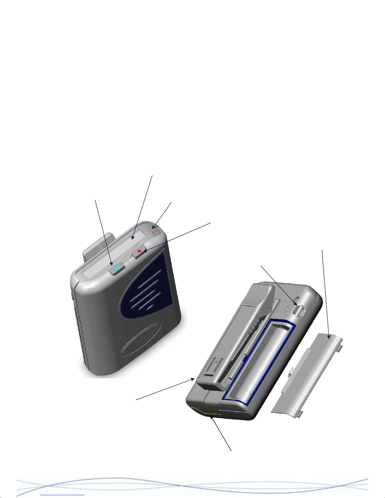
See Figure 2.1 below for the controls, indicators and User access points, associated with
the RPR 750 Series.
Figure: 2.1 User Access and Control Points
LANYARD RETAINER
BATTERY
COMPARTMENT DOOR
CHARGING &
PROGRAMMING CONTACTS
GRIPTITE CLIP
MUTE
BUTTON
LED CALL INDICATOR
ON/CANCEL/RECALL
(OCR) BUTTON
ALPHA-NUMERIC
LC DISPLAY
9
Page 13

TM1215 Iss. 6.0 RPR750
2.3 Wearing the Pager
The pager is supplied with a detachable "Griptite" clip, which is specifically designed to
enable a tight grip-fit when used for "in-pocket", or "belt" applications. The tightness of the
clip may be adjusted by varying the clip slider on the underside of the clip assembly.
An elasticised detachable Lanyard option with a metal retaining clip, is also supplied. This
may be used in conjunction with the "Griptite" clip, or as a separate method of attachment.
2.4 Operation of the Pager
2.4.1 Switching On
To switch the pager on, press the ON/CANCEL/RECALL (OCR) button once. During the
first 0.5 seconds, the pager will emit a short beep-tone, the LED will light, the vibrate
motor operate and all of the segments of the LC display will show. Following this initial
sequence, the LC display will go on to show the pager's address and a switch-on
message. The display backlight will also illuminate for the period of this sequence, which
will last for a total of approximately 8 seconds. Upon completion of the sequence, the
pager will enter quiescent mode and be ready to receive calls.
If the battery is low, the "low battery warning" buzz-tone will additionally modulate the
beep-tone during the initial sequence.
If during the switch-on sequence the pager's EEPROM cannot be read correctly (due to a
fault, or incorrect programming), then the display will show a flashing sequence of
EEEEEEEEEEEEEE. In this instance the functionality of the pager is limited to
engineering mode, absence mode (for re-programming) and OFF.
2.4.2 Switching Off
To switch the pager off, press and hold the ON/CANCEL button and then press the MUTE
button. The pager will display OFF and then switch off after 2 seconds. Once the display
shows OFF, the ON/CANCEL button may be released and it is not possible to stop the
shutdown sequence.
2.4.3 Permanent On
This is an optional programmable mode. The pager will automatically initiate the switch-on
sequence as per Section 2.4.1, when a battery is inserted and remain ON until the battery
is removed.
Should the "switch-off" button sequence (Section 2.4.2) be applied to a permanently ON
pager, it will cause the display to read RESET and the pager will then perform a reset,
followed by the switch-on sequence as per Section 2.4.1.
2.4.4 Display Modes
The Liquid Crystal Display (LCD) is a 14 character full alphanumeric device, which in the
quiescent state is always active and will show the highest priority status information
(without backlight). Where time is enabled as an option, this will be displayed.
Display reversal: - The displayed text may be inverted, to suit the User's mode of wearing
the pager. To enable this option, press the MUTE button whilst in the status interrogation
mode (see 2.4.6). The new display direction will be held in the pager's non-volatile
memory and thus will be retained, even when the equipment is switched off, until reset.
10
Page 14

TM1215 Iss. 6.0 RPR750
On-demand option: - The pager may be programmed with this feature, which means that
the display will be blank in the quiescent state until the pager has a changed status (e.g.
call), or a button is pushed.
2.4.5 Status Information
To interrogate the pager's status, from the quiescent mode, press the CANCEL button
once. This will cause status> to be displayed, followed by each programmable status
message in priority order. Each message is displayed for 1s and when the sequence is
completed, the pager will revert to the quiescent mode. The sequence is as per Table 1
below.
Description Format When Used
New Message
X new message(s)
There are x message(s) with new
status (x = 1 to 5)
Out-of-range
Out of range
Option is enabled & no in-range
system signal has been received for
3.5 minutes for MK6/7 formats & 5
minutes for POCSAG
Low battery
Low battery
Option is enabled and cell voltage is
below trigger point
Time of day
12:00
Option programmed and pager is not
out of range, or internal clock option
has been activated
Mute status
mute
Pager is in mute mode
Vibrate
vibrate
Vibrate option selected
On status
on
No other status message to display
Table 1: Status Messages
2.4.6 Receiving a Call
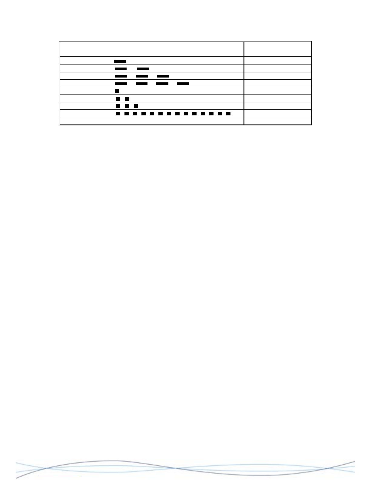
For Multitone MK6 & MK7 code formats, there are 8 different audible alert patterns (beep
codes - see Table 2), plus one silent alert function. When a call is received using these
formats, the user is alerted (where option is selected) by:
a) the chosen audible tone alert pattern (except in Mute mode); 8, 16, or 32s duration, as
programmed;
b) the Alert LED flashing in unison with the tonal alert pattern;
c) the display showing the received message;
d) pager vibration (if selected);
e) a speech message.
Where a silent alert is transmitted, functions b, c and optionally d & e, are activated.
Calls may continue to be received whilst the pager is beeping; however the sensitivity of
the radio may be reduced during this period. If a new call is received it will take priority
and the original call will be assigned a new status and placed into the memory; unless it
has been cancelled by the User before the arrival of the second call.
11
Page 15
TM1215 Iss. 6.0 RPR750
PIP/BEEP TONE ALERT PATTERN MULTITONE BEEP
CODE
Single Beep 2
Double Beep 3
Triple Beep 1
Continuous Beep 4
Single Pip 6
Double Pip 7
Triple Pip 5*
Continuous Pip 8*
Silent Alert 9
Note: * Beep codes 5 & 8 override the Escalert and mute modes. The alert is full volume
for the whole of the programmed alert period.
Table 2: Beep Alert Patterns & Beep Codes MK6 & MK7
Standard alert Beep and Pip tones are single 2.7kHz tones, timed at 125ms for a single
Pip and 500ms for a single Beep, with equal periods between each tone (125ms &
500ms) for multiple cadence alerts e.g. double beep, triple beep etc.
An optional two frequency "warble tone" is also available, which consists of alternate
67.5ms periods of 2.1kHz and 2.7kHz tones. This tone will also follow the cadence
patterns for the different alert types.
For the POCSAG variant up to 8 cadence patterns are available, which may be mapped to
each RIC and function code.
2.4.7 Cancelling Alerts
An alert may be cancelled by pressing the CANCEL button, which will terminate the LED,
tone and/or vibration alerts, but any message will be replayed from the beginning. The
cancel operation also deletes the new status from the call (see 2.4.13), but un-cancelled
calls will retain their new status until they have been fully displayed in memory replay
mode.
2.4.8 Escalating Alerts
Alert escalation (Escalert) is a software programmable option, which may be set to
commence at any point in the sequence shown in Table 3. If the vibrate option has been
selected, then this will be included at every stage in the alert, with a cadence of 2s on, 2s
off.
If the pager is in the mute mode, then the alert tone will be suppressed from the
sequences in Table 3. The Escalert option is overridden when beep codes 5 & 8 are
received (MK6/7), or RIC B (emergency override) (POCSAG) in this case, the pager will
immediately commence an alert at the stage 3 level.
12
Page 16
TM1215 Iss. 6.0 RPR750
Stage Duration Alert
1 4 seconds LED flash only, following the
assigned beep code pattern
2 4 seconds LED flash and quiet tone, both
following the assigned beep code
pattern
3 8, 16, 32 seconds, or
continuous
As per stage 2, but at normal tone
volume
Table 3: Escalating Alert Sequence
2.4.9 Extended Alert
Extended Alert is a software programmable mode, which is entered if a call is not
cancelled within the normal alert period. The sequence is as follows: -
LED - one 0.125s flash, commencing 2s after the end of the normal alert period, followed
by one flash every 2s thereafter, until cancelled.
Tone - two 0.125s normal volume pips, commencing 120s after the normal alert period
and 2 further pips every 120s thereafter, until cancelled. The time period between the pips
is 2s and they are synchronised to the LED flashes. If the pager is in Mute mode, or the
call is a Silent Alert, then the pips will be suppressed.
Vibrate - one 2s vibration, commencing 120s after the end of the normal alert period,
followed by further vibrations every 120s, until cancelled.
Notes:
(a) It is not possible to interrogate ON/MUTE status, or change modes, during an
extended alert. The alert must first be cancelled and the call viewed from
memory.
(b) The 120s alert interval is programmable from 2 to 512s, although 120 and 300
seconds are the most commonly used.
2.4.10 On/Mute Mode
A software programmable option with User definable configurations, using the MUTE
button. Whilst in the Mute mode the pager will respond to calls, but will not emit a tone
alert, or activate the speech audio channel. An alert will be notified by the flashing LED
and vibration where activated. Text messages will be displayed and stored, as will any
associated speech messages, up to the specified storage limit. The Mute mode will be
neutralised by any override beep codes received and a normal alert will be sounded.
The ON/MUTE mode configuration may be changed, by pressing and holding the MUTE
button for 1.5s whilst the pager is in the quiescent state. Each status will be displayed and
acknowledged with an audible alert, in accordance with the Table 4 below. Subsequent
pressing of the MUTE button for 1.5s, will cause the pager to cycle through the status
options as given in Table 4.
Status On Display Audio Acknowledgement
on
1 quiet pip
Mute + vibrate
2 quiet pips + 1 second vibrate
On + vibrate
1 quiet pips + 1 second vibrate
Table 4: Mute/On Mode Sequence
13
Page 17

TM1215 Iss. 6.0 RPR750
2.4.11 Vibrate Alert
A software programmable option, which once programmed may also be enabled/disabled
directly by the User, utilising the MUTE button as previously described in 2.4.10.
Note: Both the Mute and Vibrate modes are software options. If either or both of these
options are disabled, then the corresponding modes of operation described in 2.4.10 &
2.4.11 above, will not be available.
2.4.12 Call Status
Each call is given a new status when first received. This status is retained until the call is
fully displayed, either during initial reception, from the memory replay mode, or is
cancelled by the CANCEL button. If an alert is left uncancelled, then "x new messages"
will be shown on the display, where x = 1 - 5.
2.4.13 Message Retrieval & Viewing
New messages are displayed during the initial alert & speech periods unless cancelled
and received calls are automatically entered into the pager's memory store. Message
retrieval is initiated from the quiescent state, by pressing the CANCEL button once to
enter the Status mode and again to enter memory replay. If the pager is in the extended
alert mode, then the first press of the CANCEL switch will cause it to enter the memory
replay mode directly. At this point, the pager will display the "header" for the first
message, or the phrase "no messages", if there are none. If there are no messages, the
pager will return to the quiescent state after 2 seconds.
The message "header" is the first part of the message screen and may consist of a time
stamp or a message number (Mx, where x = 1 - 5), plus the initial part of the message if it
is more than 14 characters (all if it is less), as in the examples shown below: -
Header Display Rest of message
Time stamp 10:20 visitor in reception**
14:35 meet me in conf room 15:00 - ADT**
Message No. M1 please come to reception**
(No time stamp) M2 PHONE 020-1647-98452**
Further pressing of the CANCEL button, will cause the pager to scroll through the stored
message "headers". If it is required to read a message, do not press the CANCEL button
again after reaching the desired message "header", the selected message will then scroll
through automatically, after a 1.25s interval. A message will terminate with **, or **? if
there is an abnormal termination, or any doubtful elements. The final screen will display
for 2.5s and then the pager will return to quiescent mode, if no further button operations
are instigated.
The speed of message viewing may be changed, by use of the MUTE button. If the MUTE
button is pressed during viewing, then the message is held at the current screen.
Releasing the MUTE button will cause the next screen to be displayed immediately. If the
MUTE is pressed and released during the final screen of a message, then the message
"header" is again displayed and the message can be viewed again.
If the CANCEL button is pressed whilst viewing a message, the viewing of that message
will be cancelled and the pager will revert to the preview mode, with the next message
"header" displayed. If all message "headers" have been viewed, then the pager will revert
to the status interrogation mode.
14
Page 18

TM1215 Iss. 6.0 RPR750
2.4.14 Message Replay Order
If there are new messages, then only these will be recalled. Once all the new messages
have been recalled, the pager will exit the memory replay mode and it will be possible to
view all the messages in the memory. These will be recalled in reverse order of reception
i.e. the latest message first.
2.4.15 Speech Calls (not POCSAG variants)
When a speech call is received, the alert is 4 seconds of a "Stage 3" alert (see Table 3,
section 2.4.9). After the alert period, the speech audio channel is opened and once
speech has commenced, it may only be terminated by: -
(i) a termination signal from the system encoder;
(ii) system time-out (options - no time-out, 10s, 30s, or 150 seconds), or
(iii) pressing the CANCEL button. If a call has been terminated during the alert period, a
further press of CANCEL will terminate speech.
If a call is terminated by either of methods (i) or (ii), then the call will remain un-cancelled
and be stored with a new status. If the option is enabled, the pager will then enter the
extended alert mode.
If the call has been terminated by pressing the CANCEL button during the speech period
i.e. within the time-out period, or before the termination signal from encoder, then it is
possible to re-open the speech channel, with a further press of the CANCEL button.
Any speech calls received whilst in the mute mode and without an override beep code, will
be stored without the speech channel being opened.
2.4.16 Re-playing Stored Speech (not POCSAG variants)
A speech message may be stored by the pager, but replay is not possible until the original
speech call has been completed, regardless of whether the calI has been cancelled and
the speech channel closed. Up to 120 seconds of speech may be held in the memory, in 5
equal memory segments of 24 seconds each. Any speech message exceeding this period
will be heard in full at the point of original reception, but will be truncated for storage
purposes. New calls will be allocated to the next available memory slot up to the
maximum limit and when full, new messages will overwrite the oldest stored message.
If a call has an associated speech element, which was stored when it was received, this
speech may be replayed whilst the retrieved message is being displayed.
Any stored speech will start when the message header is displayed. If the CANCEL button
is pressed at any time, the replay will be terminated and the next message will be
retrieved. Any speech associated with this new message will automatically start to be
replayed.
If the MUTE button is pressed at any time during a message replay period, the message
header will be redisplayed and the re-call cycle will start over again from the beginning.
15
Page 19

TM1215 Iss. 6.0 RPR750
2.4.17 Speech (BEEP Tone) Volume Adjustment (not POCSAG variants)
To adjust the volume of the speech messages and beep tone where programmed as an
option, the pager must be in the quiescent state. First push the MUTE button, followed by
the OCR button. The display will show the current volume level and this may then be
adjusted by further pressing the OCR button to increase the volume, or the MUTE button
to decrease. When the desired level is reached, release any buttons and the pager will
return to its quiescent state.
2.4.18 Tone & Speech Only Calls
If there are no messages, or speech associated with a call, then the message display will
show as "tone call n" for the duration of the alert, where n is the Multitone Beep Code
number (see Section 2.4.6, Table 2).
For a "speech only" call (not POCSAG variants) the message display will read as speech.
In both instances, messages may be preceded by a time stamp or message number.
2.4.19 Beep Code Alpha
Beep Code Alpha is when one particular pre-programmed message is always assigned to
a specific beep code. When this code is received, the same message is always activated
and displayed. Up to 4 alphanumeric beep code messages, each of up to 14 characters in
length, may be programmed into a pager.
2.5 OPTIONS & FEATURES
2.5.1 Time Of Day
The Time Of Day function may be derived from either one of two sources. If the system on
which the pager is to be used has an "off-air" time signal, then this option may be enabled
during the software programming of the pager. Alternatively, if time notification is required
on a pager not allocated to a system with an "off-air" time signal, then the internal clock
may be activated.
Time is displayed during quiescent conditions and takes the form: -
Hours: Minutes
3:17
15:17
Where time has not been selected, then the pager will display on status. Time will be
overridden by higher priority status messages such as new message, out of range and
low battery.
Off-air time signal - If this option has been selected, the display will show the symbol --:--
in the quiescent state, until the first valid time signal (transmitted every minute) has been
received from the system. If the pager should go out of range of the system and no time
signal is received for 2 minutes, then this symbol will also be displayed until a valid signal
is again received.
Internal clock - where the off-air time signal option is not enabled, it is possible to activate
and set the pager's internal clock. To set the time, press the CANCEL button during the
switch-on sequence and the time-of-day screen will be displayed. This screen will initially
show the hours flashing.
16
Page 20

TM1215 Iss. 6.0 RPR750
To change the hours repeatedly press, or press and hold the MUTE button, until the
desired hour is displayed. When this point has been reached, press the CANCEL button
and the minutes will start to flash. Press the MUTE button as before, until the desired
minutes are displayed. To complete the set-up, press the CANCEL button and the pager
will continue the switch-on sequence, starting at the address display for MK6/7 variants, or
the switch-on message for POCSAG variants.
If an incorrect time is entered, the CANCEL button may be pressed during the switch-on
sequence and the initial time-of-day screen will be re-displayed and the time may be reentered. To reset the time on a pager which has already been switched-on, simply turn
the pager off and on again and follow the set-up sequence. If a pager has the permanent
on option activated, reset the pager as per Section 2.4.4. and follow the time-of day set-up
sequence.
2.5.2 Call Comparator
The Call Comparator is a software programmable option, which enables the pager to
recognise calls that are a repetition of a previous call, sent within a pre-determined time
after the original call. The pager will ignore any repeated calls identified by the
comparator. The time limit can be programmed for periods of 30s, 120s and 300s after the
original call.
The exception to this will be for message calls, where the original call has not been
decoded with 100% confidence. In this case the subsequent call will be accepted and will
overwrite the original message in the pager's memory. In both cases however, a normal
alert sequence will be generated.
2.5.3 Out of Range Warning
If enabled, the Out Of Range Warning, will notify the user if the pager has not received a
valid signal for a preset time, nominally 3 minutes 30 seconds for on-site variants and 5
minutes for POCSAG variants. Combinations of alert options are available, including
visual only, audible plus visual, or either option plus vibrate.
The audible/visual option enables an out of range warning on the display for 4 seconds,
accompanied by a 2s quiet buzz (512Hz). Pagers with the audible warning enabled, will
also produce a buzz when the CANCEL button is pressed whilst the receiver is out of
range. For the visual only alert, just the message is displayed. In all cases when selected,
the vibrate option will cause several short pulses during the alert period.
After the 4s alert period, the pager will return to the quiescent mode. The range status
may be checked at any time, by using the status interrogation as described in Section
2.4.5.
2.5.4 Low Battery Warning
It is advised that this option is not enabled for use with rechargeable cells.
The battery condition is continually monitored and if a low battery voltage is sensed the
pager will continue to operate, but the battery must be changed at the earliest opportunity
(usually within the next 24hrs., depending upon system traffic levels), or continued
operation cannot be guaranteed.
17
Page 21

TM1215 Iss. 6.0 RPR750
When enabled, this option may be programmed for audible, visual and tactile alert
options. A warning may be activated under the following conditions: -
(i) at switch-on, the switch-on tone will be additionally modulated by a buzz tone;
(ii) any alerts will be modulated by a buzz tone;
(iii) the battery condition may be checked at any time, using the status interrogation
mode as described in section 2.4.5. If it becomes the highest priority message, then
a pager with the continuous display option activated and in quiescent mode, may
show an abbreviated warning message, with a time stamp.
2.5.5 Absence & Charging
Use only Multitone specified charging racks/units and programming
jigs.
Only pagers fitted with rechargeable batteries should be inserted into a
rack or charger!
Three contacts are provided at the base of the pager, to provide absence registration and
battery charging. These facilities may be provided by either, an absence/charging rack
which has a data-bus link to a central control system, a charging-only rack, or a single
desk-top charging unit.
When a pager is inserted into an Absence Rack, it will automatically be switched into the
absence mode. A pager which is already on will reset and a pager which is off, will switch
on and enter the absence mode. No paging calls will be accepted whilst the pager is
in the rack and any stored messages will be erased.
When inserted into a rack, a pager may display a programmable message of up to 9
characters. Unless programmed otherwise, the default message will be the pager's RIC
(receiver identity code) number. This message may be programmed either prior to
bringing the pager into service, or new alphanumeric messages may be transmitted to it
via the absence rack data bus.
Data exchange between the pager and the controlling system whilst the pager is in a rack,
allows the system to recognise the pager's out-of service status and make this information
available to system users. The system may also interrogate the pager for other
information, or send messages to the pager for display.
The pager's display orientation will be corrected for viewing in the rack, but will revert to
the user-programmed direction when the pager is removed from the rack. The "alert" LED
will be illuminated at half brightness during the charging cycle.
When a pager is removed from a rack, it will automatically enter its switch-on sequence.
When a single-unit charger or charge-only rack is used, the pager may still receive calls,
but its radio sensitivity may be impaired. The vibrate option will be switched off.
2.5.6 Test Mode
A Test Mode function is available, which is externally programmable from an absence
rack, or programming jig. This mode enables a short alert beep (0.5s tone & LED) and a
message display (TEST + time stamp), which overrides the call comparator and any other
programmed alert options. By enabling this function and transmitting a continual series of
calls with short repeat times to the pager's address, it provides a quick method of testing
pager sensitivity and also assessing site coverage.
18
Page 22
TM1215 Iss. 6.0 RPR750
In the quiescent state, the pager will display *TEST MODE*, instead of status.
Additionally, if the pager is in mute mode the tone alert will be suppressed, unless an
override beep code is transmitted. If a call is sent to a single pager in test mode, then any
message or speech will be ignored, but if an all-call address is used then the pager will
open the speech circuits for 2 to 4 seconds, to test the speech channel.
For test purposes a counter is incorporated, which will record the number of calls (up to
255 before resetting to zero) received in test mode and store this number in the EEPROM,
when the pager is reset, or turned off. This number may be reset, or retrieved by using a
programming unit.
Open channel speech selection (MK6 & 7 variants only) is available in test mode, which is
activated by pressing and holding the CANCEL button for 2 seconds. The speech channel
will then remain open until the CANCEL button is pressed again.
2.5.7 Batteries, Changing the Battery & Battery Care
The pager can be used with any 1.5 Volt nominal AA (LR6) sized primary cell, or for rechargeable applications NiMH secondary cells. It should be noted that battery life
expectancy may vary greatly with the cell supplier and chemistry, especially with the rechargeable options.
In order to maximise battery life, cancel any alerts as soon as possible and switch-off the
pager when not in use. If the pager is not to be used for a long period, it is recommended
that the battery be removed.
NOTE: Any stored messages will be retained by the pager for approximately 12 hours
when the battery is removed, or the pager is turned off.
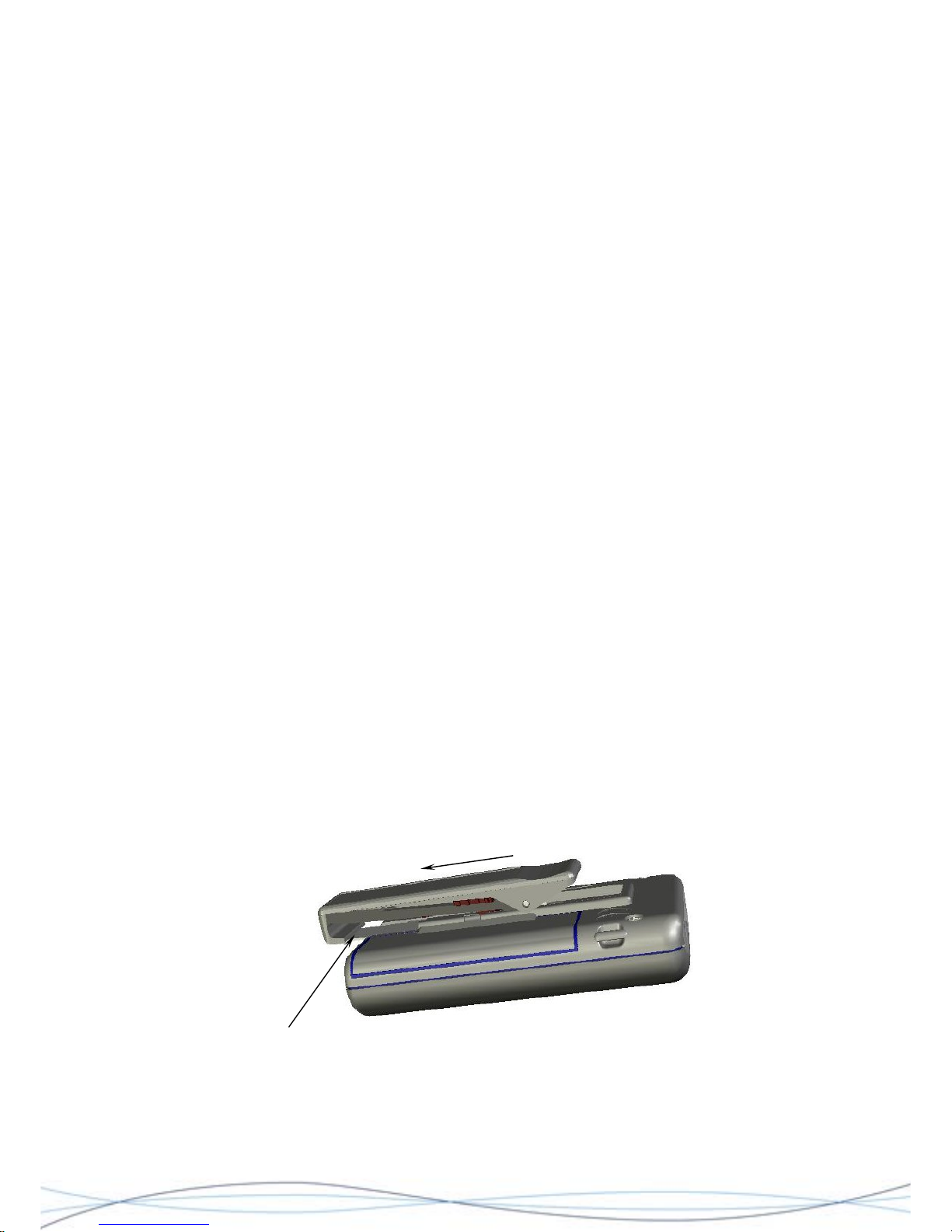
To change the battery, ensure that the pager is switched off and proceed as follows: -
Hold the unit in one hand with the front facing downwards. Insert the blade of the Battery
Door tool under the bottom edge of the metal back-plate for the clip and gently lift enough
to release the clip from its retaining slot. At the same time, slide the clip assembly towards
the base of the unit with your thumb.
Figure: 2.2 Clip Removal
Slide clip
Metal back-plate (insert Battery Door
Tool or thin blade under this edge)
19
Page 23
TM1215 Iss. 6.0 RPR750
20
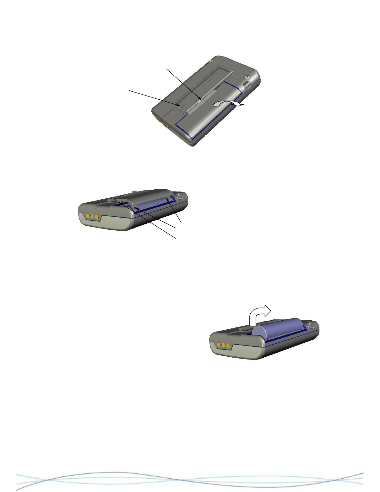
Using the Battery Door Tool, lift and release the battery-door catch and with forefinger,
pull the door away from the case, in the direction shown in the illustration.
Clip back-plate retaining slot
Battery door catch
Figure: 2.3 Battery Door Removal
Ensure that the battery door lugs are
lifted clear of the case and remove the
door.
Battery door
locating/locking lugs
orefinger
Figure: 2.4 Battery Door Lug Positions
Remove the battery by placing your forefinger onto the positive end-cap and lifting the
battery upwards, at the same time pushing slightly backwards against the negative
contact spring.
Remove the battery by placing your f
onto the positive end-cap and lifting the
battery upwards, at the same time pushing
slightly backwards against the negative
contact spring.
Figure: 2.5 Battery Removal
Battery replacement is the reverse of the above sequence. Place the battery base against
the negative contact spring and compress slightly, at the same time pushing the battery
into the compartment and engaging the positive end-cap against the positive contact of
the pager.
Page 24
TM1215 Iss. 6.0 RPR750
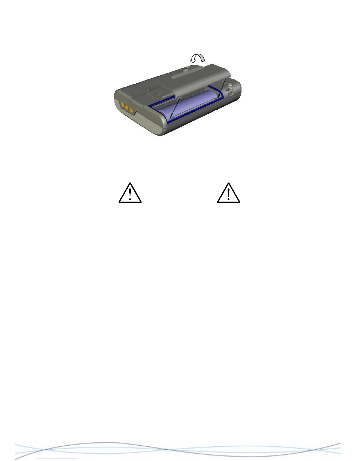
WARNING
To replace the battery door, firstly locate the battery door lugs into the positions shown
and then rotate the door downwards, compressing the battery and surrounding gasket.
Push until the second set of lugs and the catch engage and hold the door closed.
Figure: 2.6 Battery Door Re-fitting
Finally, whilst holding the battery door in place, re-insert the metal clip-back into the
guides on the case-rear and slide the clip into place, ensuring that the retaining lug relocates into the slot in the case-back.
For the Intrinsically safe variants of the pager, only specific types of cell are to be
used, as these form part of the safety certification. Do not use any other cell types,
as this may contribute to a hazardous situation. Refer to the User Guide for battery
options.
21
Page 25
TM1215 Iss. 6.0 RPR750
3 Technical Description
3.1 PHYSICAL CONSTRUCTION
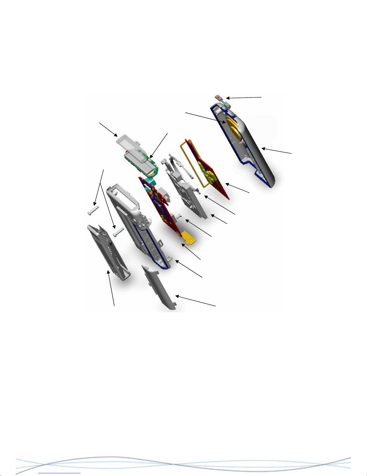
The RPR 750 Series receiver electronic hardware comprises two main printed circuit
board (PCB) assemblies, contained in a plastic housing. See Fig. 3.1.
Case Screws
Window
Display PCB
Decoder PCB
Case Rear
Battery Compartment Door Griptite Clip
Loudspeaker
Radio PCB
Rubber Spacer Mat
Loudspeaker Retaining Clip
PCB Fixing Screw
Function Buttons
Case Front
Figure: 3.1. Major Assembly Parts - RPR 750 Series
The case is constructed from Bayblend PC/ABS plastic in two main parts, front & rear,
with a detachable battery compartment door assembly in the case back. The principal
PCB's, the Radio and Decoder, are mounted one over the other, with electrical connection
between them achieved by means of a multi-way plug & socket assembly. The PCB
combination is then affixed to the case rear. The case front is detachable and holds the
loudspeaker assembly.
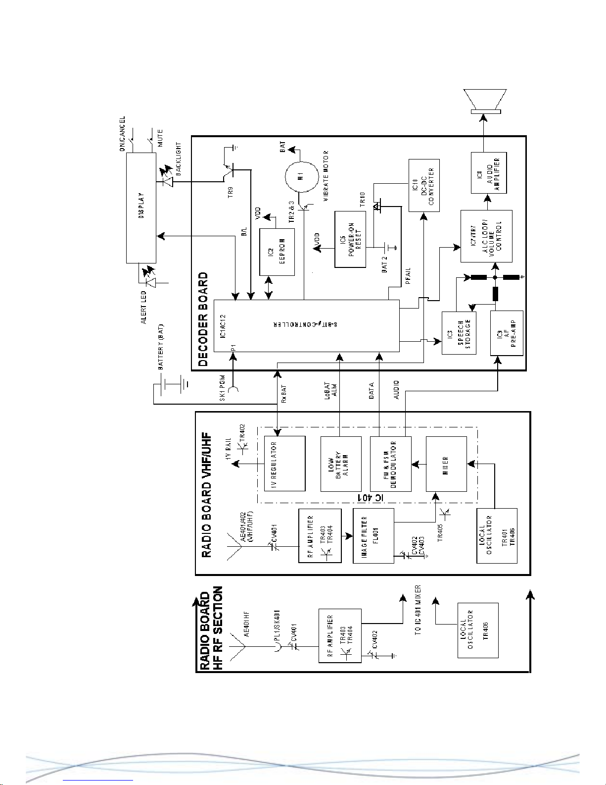
Radio PCB - this PCB contains the Dual Conversion radio receiver, a 1V regulator and a
low battery alarm function. Demodulated data and audio signals from this board are fed to
the Decoder PCB.
Decoder PCB - also sub-mounted on this PCB, are the LC display PCB and the vibrate
motor. The PCB contains the central processor, data decoding, speech storage and audio
amplification, the LC visual display drivers and the LC message screen and alert lamp.
22
Page 26
TM1215 Iss. 6.0 RPR750
3.2 FUNCTIONAL DESCRIPTION
23
Page 27

TM1215 Iss. 6.0 RPR750
.2.1 Radio Board RF Section (VHF/UHF)
he RPR 750 Series VHF/UHF radio is a dual conversion superhet configuration. The
03
he output of the RF amplifier passes to the Image filter, which attenuates the 1
st
Image
408, L401 and CV403 form a further parallel tuned circuit, which is again adjusted for
0dB
he local oscillator (LO) is formed by XL401, TR406 and associated components. C417
s
he mixer circuit, comprising TR405 and associated components, receives the output
it
he output of FL401 is fed into IC401, to be mixed with the second local oscillator. This
are
f
his signal is then passed through filter FL403, to remove any unwanted products and
.2.2 Radio Board RF Section (HF)
he RPR 750 Series HF radio is a single conversion configuration. The RF signal is
erial AE1 is tuned and matched by CV401 and banded components, C434, C453 and
s
he local oscillator is formed by crystal XL401 and TR406, plus associated components.
he crystal frequency is (Channel Frequency - 455kHz)/2.
3
T
incoming RF signal is detected by the loop antenna AE401/402 and is finely tuned by
capacitor CV401. C433 and C435 provide matching to the RF amplifier formed by TR4
and TR404, which provides in the order of 10dB gain.
T
frequency, signals outside of the required band and also matches the output of the RF
amplifier to the mixer stage. L405/406 and CV402 form a parallel tuned circuit, which is
adjusted to have minimum loss at the frequency of operation.
C
minimum loss at the frequency of interest. Additionally L401 and C408 form a series
resonant circuit, which is close to the 1
st
Image frequency. This gives approximately 4
attenuation at the Image frequency.
T
and L403 tune the collector of TR406, to the third harmonic of XL401. This circuit provide
the correct Local Oscillator frequency and reduces the level of other harmonics. For the
UHF receiver, further harmonic reduction is achieved by tuned circuits L408, C440 and
L402, C410. Fine frequency adjustment is achieved by CV404.
T
from the Image filter and mixes it with the output from the local oscillator, to produce a
45MHz (UHF) or 21.4MHz (VHF) product signal, which is selected by the resonant circu
of L407 and C439. The resultant signal is then fed into xtal. filter FL401.
T
runs at 44.545MHz (20.945MHz for VHF) and comprises XL402, associated tuning
components and IC401. The frequency of this oscillator is not variable, so any errors
compensate for by the tuning of the first LO. The output from FL401 is fed into pin 20 of
IC401 and mixed with the LO output, to produce a second IF signal at 455kHz on Pin 3 o
IC401.
T
provide further selectivity. The output of FL403 is then fed back into the IF amplifier of
IC401, on Pin 5.
3
T
received by the ferrite + loop aerial AE1, which is mounted on the Decoder board and
connected to the Radio board via PL1/SK401.
A
C435. The incoming signal is matched to the base of TR403, which in conjunction with
TR404 forms a cascade rf amplifier with a gain of 15 - 20dB. Tuning and matching of thi
amplifier is provided by L405/406, CV402, C455, C450, C405, C452 and C406. The
output of this stage is coupled to the mixer stage of IC401, via C419.
T
This circuit doubles the frequency generated by XL401 and the circuit formed by L403 and
C417 selects the second harmonic. The resultant signal is fed into IC401 via C451.
T
24
Page 28

TM1215 Iss. 6.0 RPR750
.2.3 Demodulation & Detection (All RF variants)
401 is a multi-functional device, combining the operations of mixer, local oscillator, IF,
he IF amplifier of IC401 amplifies the signal and also removes any AM components in
d
he detector circuit is also internal to IC401 and is a Quadrature Demodulator with two
n
he output from the detector stage is on Pin 10 of IC401. This gives an audio output to
n Pins
he output of the data filter is internally connected in IC401 to the FSK reference voltage
431. The
he
dditional facilities provided by IC401 include a 1V constant voltage source, which is fed
r
low battery voltage alarm is made available on IC401, Pin 16. This circuit is triggered
.2.4 Decoder Board
he Decoder board is most easily considered in three functional sections: digital
.2.4.1 Digital
his section is based around the 8-bit micro-controller IC1 (MKI variant) or IC12 (MKII
1/IC12 contains a flash-based memory (programmed via SK1 pin 7 PGM, which also
r
3
IC
detector, low battery alarm and a 1V regulator.
T
the waveform, in order to shape the data signal to a "square" format, before being passe
to the detector stage.
T
inputs. One signal input directly connects internally from the IF amplifier stage and a
second signal from the IF is passed out via Pin 8 to a phase delay circuit, comprising
C445, R426, C444 and ceramic discriminator FL402. The phase delay is dependant o
the frequency of the IF signal and is 90 degrees at the receiver's allocated centre
frequency. The delayed signal is fed back into IC401 on Pin 9.
T
Pin 9 of PL401 and test point TP1; the latter providing a measurement test point for
receiver tuning, using SINAD measurement techniques. The detector output also
connects to R414, R411, R410, C421 and C422, which connect back into IC401 o
11 and 12, to form a data filter network in conjunction with the integral op-amp. This is a
unity gain low-pass filter, which reduces high frequency noise.
T
(FSKREF) charge/discharge circuit. This circuit is controlled by a logic signal from the
central Processor IC1 on the Decoder PCB, via Pin 14 and determines the
charge/discharge rate of the capacitor used to store the FSKREF voltage, C
reference voltage is fed into the FSK comparator, along with the detected signal from t
low-pass filter. The comparator then "shapes" the FSK data signal, to reduce errors due to
waveform distortion and feeds the resulting signal out on to Pin 15, to be passed on to the
Decoder PCB.
A
from the battery via the emitter of TR402. The base of TR402 is controlled by the regulato
circuit via Pin 17 and provides the 1V level onto the collector of TR402. Level monitoring
is fed back into IC401 via Pin 18. This voltage is used to power the RF stages of the
receiver.
A
when the battery voltage drops to 1.1V and the output pin becomes "high". This status is
fed to the main processor IC1 on the Decoder board, which then activates the audio and
visual alarm circuits.
3
T
processing, audio amplification and power management.
3
T
variant), a 4kbit serial EEPROM IC2 and the display module (LCM).
IC
allows access to the contents of IC2 via IC1/IC12 and provides all the function control fo
the pager and data decoding. The main clock frequency for the IC is derived from XL3 @
25
Page 29

TM1215 Iss. 6.0 RPR750
4.19MHz, with a sub-system clock XL2 operating on either 32.768kHz or 38.4kHz,
depending upon the Baud rate selected for the pager (512 or 1200).
The radio circuits are activated by IC1/IC12 (RXEN-SK1/13) for a brief period every
second, so that a check may be made for the presence of a preamble signal. If preamble
is detected, then the radio is held on and the demodulated data signal is downloaded
(DATAP) from the Radio board via SK1/11, for decoding by IC1/IC12.
At the same time IC1/IC12 reads the pager address and the programmed options data
held in the EEPROM IC2 and if the decoded data is recognised as valid, then IC1/IC12
generates a call alert sequence which includes the options of flashing the Alert LED (HS),
an audible tone alert (BEEP), message text display and speech and/or vibrate (VIBRATE).
Communication between IC1/IC12 and the Display Module is via a high-speed serial data
bus, along a 12 way flexible connecting strip (signals SI, SCL, A0 & SO). The LCM
contains the LC display, a driver IC, control switches (OCR & MUTE), the red Alert LED
and LED backlighting facilities.
IC1/IC12 controls the radio circuits via SK1 pins 13 (RXEN), which enables the power
ON/OFF function and pin 12 (F_CHG), which controls the FSK reference voltage for the
data comparator (see preceding Radio PCB description).
Battery status data is also fed from IC401 via SK1 pin 10 (LOWB), which is processed by
IC1/IC12 to sound a “low battery” alert. In the event of the main battery being removed,
IC1/IC12 will also cause the switchover to the back-up battery, to maintain the internal
clock and messages.
3.2.4.2 Audio
The Audio section consists of speech storage chip IC3, a pre-amplifier IC9, digital
potentiometers IC7 and IC11 (MKII only) and power amplifier IC8.
When a speech call is received, the audio from the radio is fed from SK1 pin 9 (RX
AUDIO) into the pre-amplifier IC9 (pin 3). IC9 and IC8 are normally held quiet until a
speech call is detected by IC1/IC12, which then activates IC9 via (EN2) and IC8 via (EN1)
control lines. When the pager is in battery economy mode, or receiving calls, both the
control lines are cleared, putting the audio section into standby mode.
The output from IC9 (pin 4) is fed jointly to the input of stored-speech chip IC3 (SPEECH
IN) and also directly to input of IC8 (pin 1). In company with this, the output from IC3
(SPEECH OUT) is also fed to the input of IC8 (pin 1).
With this configuration, when a speech call is first received, both (EN1) and (EN2) control
lines are activated by IC1/IC12 and the audio is fed to both the loudspeaker and the
speech storage chip IC3 simultaneously. When a stored speech call is selected to be
replayed from IC3, only line (EN1) is enabled.
The functional gain of the power amplifier IC8 is controlled by the agc circuit combination
of TR7 and IC7, the latter being a digital potentiometer. The gain value set in IC7 is
determined from IC1/IC12, by toggling the control lines (CS1) and (U/D), enabling the user
to set the speech audio signal level entering IC8.
The alert tones are fed directly from IC1/IC12 (BEEP) output to digital potentiometer IC11
and then to the final power amplifier IC8.
IC8 provides a balanced drive to the loudspeaker. The overall gain of this final device is
held by R49, R50, R24 and R65.
26
Page 30

TM1215 Iss. 6.0 RPR750
3.2.4.3 Power management
This section comprises IC5 and IC10, under the control of IC1/IC12.
IC10, L1 and D29, form a voltage converter, which boosts the nominal battery voltage to
3.3V (VDD). When a battery is fitted, TR’s 8 & 10 are enabled and the output of IC10 is
connected to the digital sections of the pager.
The presence of the main battery is detected by TR8 (B+), which controls the status of
TR10. At the same time, the backup cell BATT2 is charged from the main battery, which
typically takes around 24 hours from flat. If the main battery fails or is removed, TR8 is
switched off, which status is signalled to IC1/IC12 (PFAIL). At the same time TR10 is
turned off, effectively isolating IC10 from the backup cell. BATT2 will maintain the internal
clock and message memory function for a minimum of 12 hours.
IC5 is a voltage detector, which controls the reset signal to IC1/IC12. When the supply line
(VDD) falls below 2.2V, IC5 triggers the (RESET) line to IC1/IC12, resulting in the pager
losing any messages and re-setting its real-time clock.
Also included within the power management section, are the driver for the vibrate motor
TR’s 2 & 3, the Alert LED driver TR6 and the display module backlight driver circuit
combination, TR9/L2.
The pager is charged via external contacts CONN1(CHG) + CONN1(GND ) and R54/D25
to the B+ rail. The presence of a charging voltage is signalled to IC1/IC12 by TR4
(CHGDET).
3.2.4.4 Programming
When programming the pager from an absence rack or programming pocket, serial data is
transferred from the external contact CONN1 (PROG) to the IC1/IC12 (PROGB) pin.
Resistor R38 provides a pull-down function to IC1/IC12 and the diode D26, provides ESD
and excessive voltage protection for the external programming contact.
27
Page 31

TM1215 Iss. 6.0 RPR750
4 Servicing (excluding IS variants)
STATIC SENSITIVE DEVICES ARE USED WITHIN THIS EQUIPMENT. CARE MUST BE
TAKEN TO ENSURE THAT DAMAGE TO THESE DEVICES, IS NOT CAUSED BY HIGH
LEVELS OF STATIC ELECTRICITY.
4.1. Routine Maintenance
Routine maintenance of the RPR 750 Series receiver is limited to replacement of the
battery when required and surface cleaning of the unit, using a lint-free cloth moistened
with soapy water.
4.2 Service Policy
Where possible, it is advocated that faulty units are returned to Multitone for repair. Where
it is necessary to effect repairs in the field, these should be limited to the direct
replacement of the identified faulty module, or broken case part, only. Any component
removed, must be replaced by the relevant item as specified in Section 6.
Any work should only be carried-out by qualified personnel, in correctly equipped and
authorised workshops. Liability is not accepted for any work carried-out by third parties.
Workshops must be free from hostile radio interference, or equipped with suitable
screening facilities.
Work on Intrinsically Safe variants of the equipment must only be carried out by
Multitone trained personnel, or authorised service centres. When re-programming
equipment, only use the specified Multitone P648 Programming Unit, otherwise the
Intrinsic Safety status of the equipment is void.
4.3 Test Equipment & Tools
The following tools and test equipment may be required during any servicing procedure: -
• IBM PC or equivalent
• Multitone P648 Programming Unit & software
• Multitone P645 Test Encoder, cable & software
• Multitone Fault finding jig
• RF Signal Generator
• SINAD Meter
• Oscilloscope
• AC Millivoltmeter
• RF Millivoltmeter with high impedance/low capacitance probe
• Digital Multimeter
• TEM Cell
• DC Power Supply 1-1.5V
• Anti-static Workstation
• Surface-mount component handling tools
• Modified case-front assembly
• Trimming Tools - tip sizes 0.4 - 1.8mm
• M2 cross-point screwdriver
28
Page 32
TM1215 Iss. 6.0 RPR750
4.4 Dismantling the Pager
Before dismantling the pager, ensure that it is switched off!
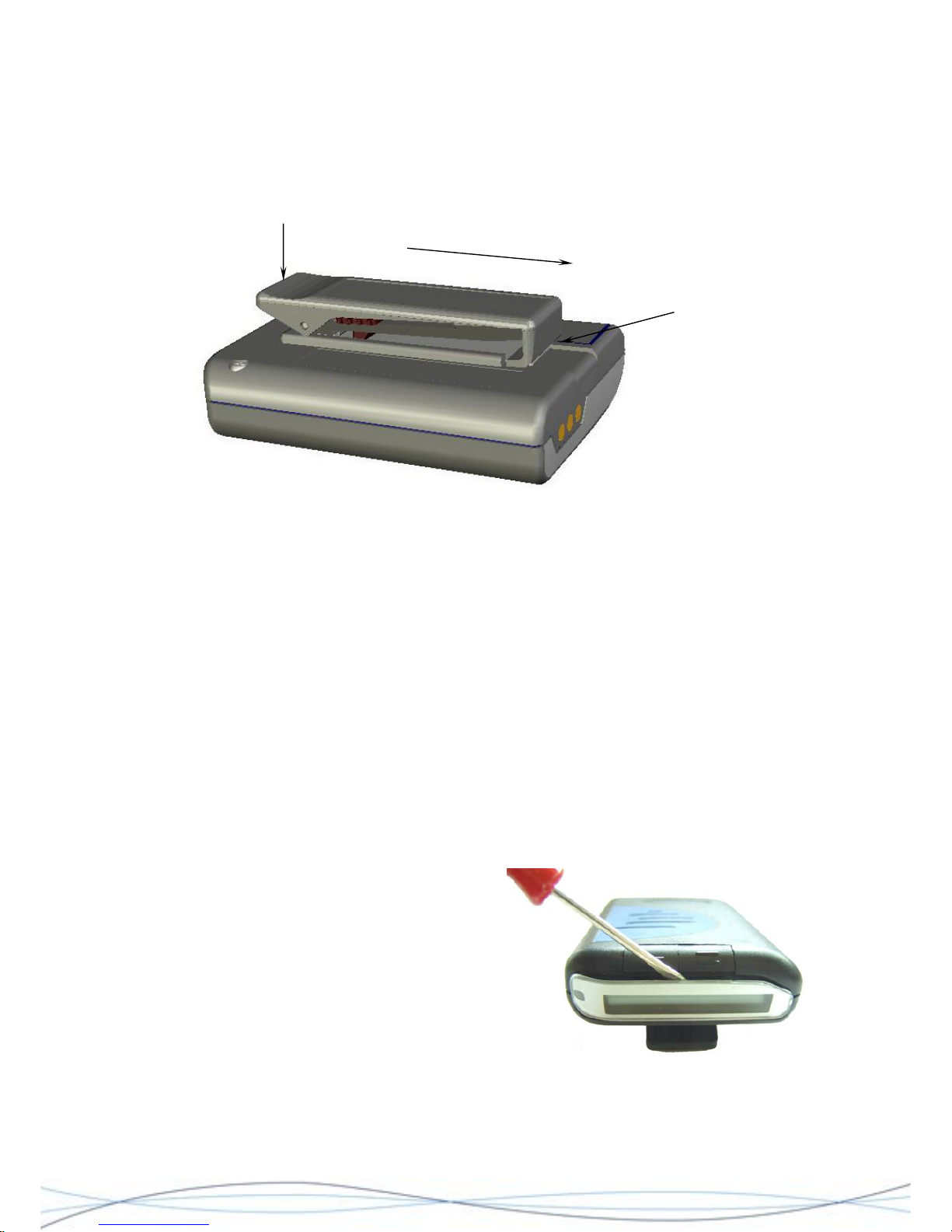
4.4.1 Clip Removal & Replacement
Slide Clip Assembly to remove
Insert Battery
Door Tool or b
under the edge o
the metal retaining
clip and lift
lade
f
Figure: 4.1
Removal - Refer to Fig. 4.1. Hold the pager in one hand and push down on the top of the
clip, to raise the bottom "grip-edge". Gently insert the Battery Door Tool edge marked
"clip" or similar blade, under the metal back-plate of the clip and lift enough to release the
retaining catch. Once the catch has lifted sufficiently, slide the clip towards the bottom of
the pager, by applying thumb pressure to the clip top.
Replacement - Before attempting clip replacement, ensure that the grip adjustment slider
is set to the top of the clip and that the metal back-plate has been straightened. To
replace the clip, insert the top of the metal back-plate into the grooves of the clip housing.
Slowly push the clip home, until the retaining catch locks into position.
4.4.2 Case Removal
Remove the clip assembly (as described in 4.4.1) and the battery door. The next stage of
removal varies according to the age of the equipment under repair and is determined by
the type of OCR/Mute button fitted.
For older equipments fitted with the “flush”
style of button, proceed as follows. Do not
try to remove the window by this
method on later units, as it is moulded
as part of the case rear.
Insert the blade of a small screwdriver, or
similar blunt blade, between the edge of
the window and behind the buttons. Gently
lift the blade and prise the open the edge
of the window. Once lose, lift the window
away from the unit and discard. Do not
re-use the window, replace with a new component.
29
Page 33
TM1215 Iss. 6.0 RPR750
Place tip of finger on the top edge (display) of
a button and pull forward towards the front of
the unit, until it releases from the main
assembly. Repeat the process with the second
button and carefully retain both components.
From this point, dis-assembly is the same for both the early equipments and the later
assemblies with the “raised” OCR/Mute buttons. For later equipments the buttons may
remain in situ in the case front, unless replacement is required.
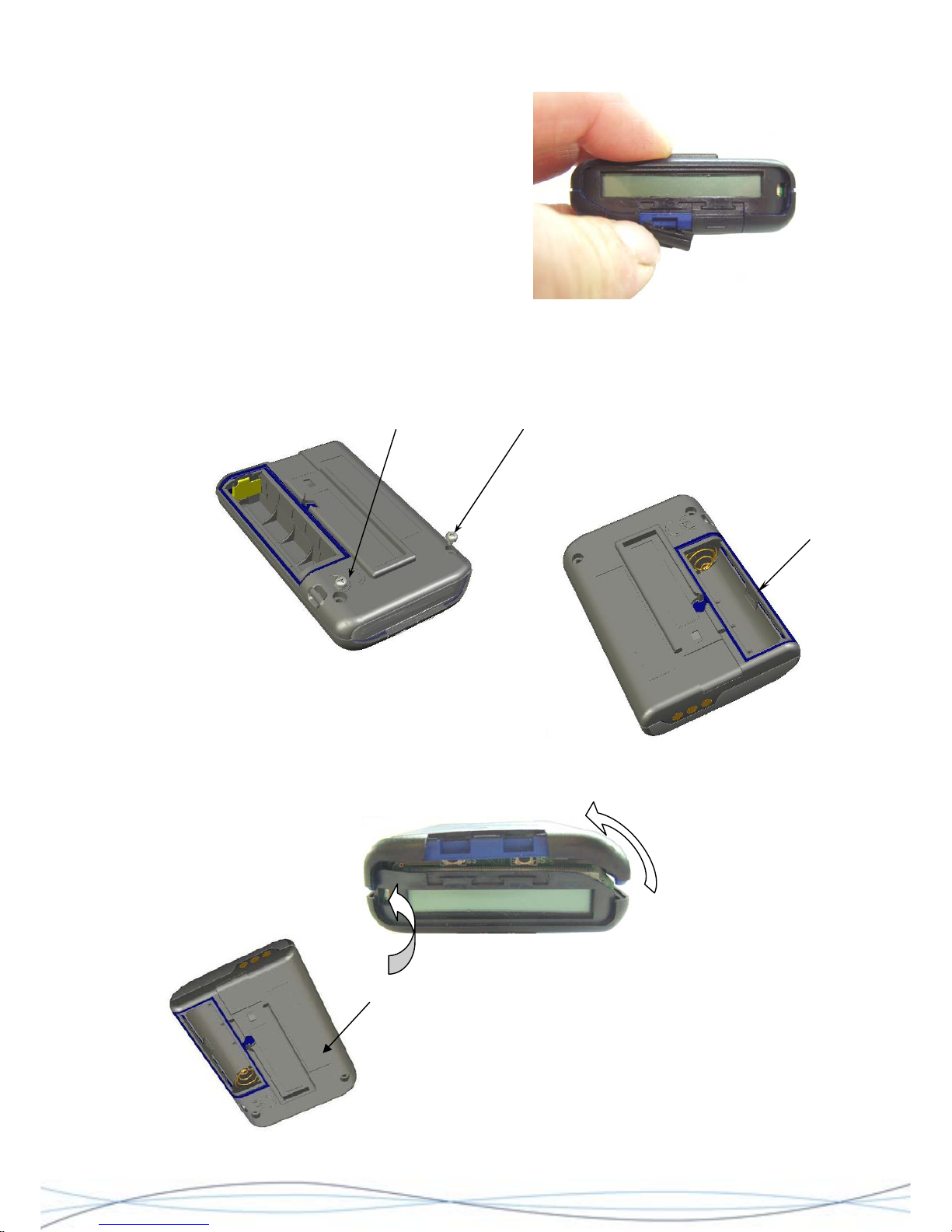
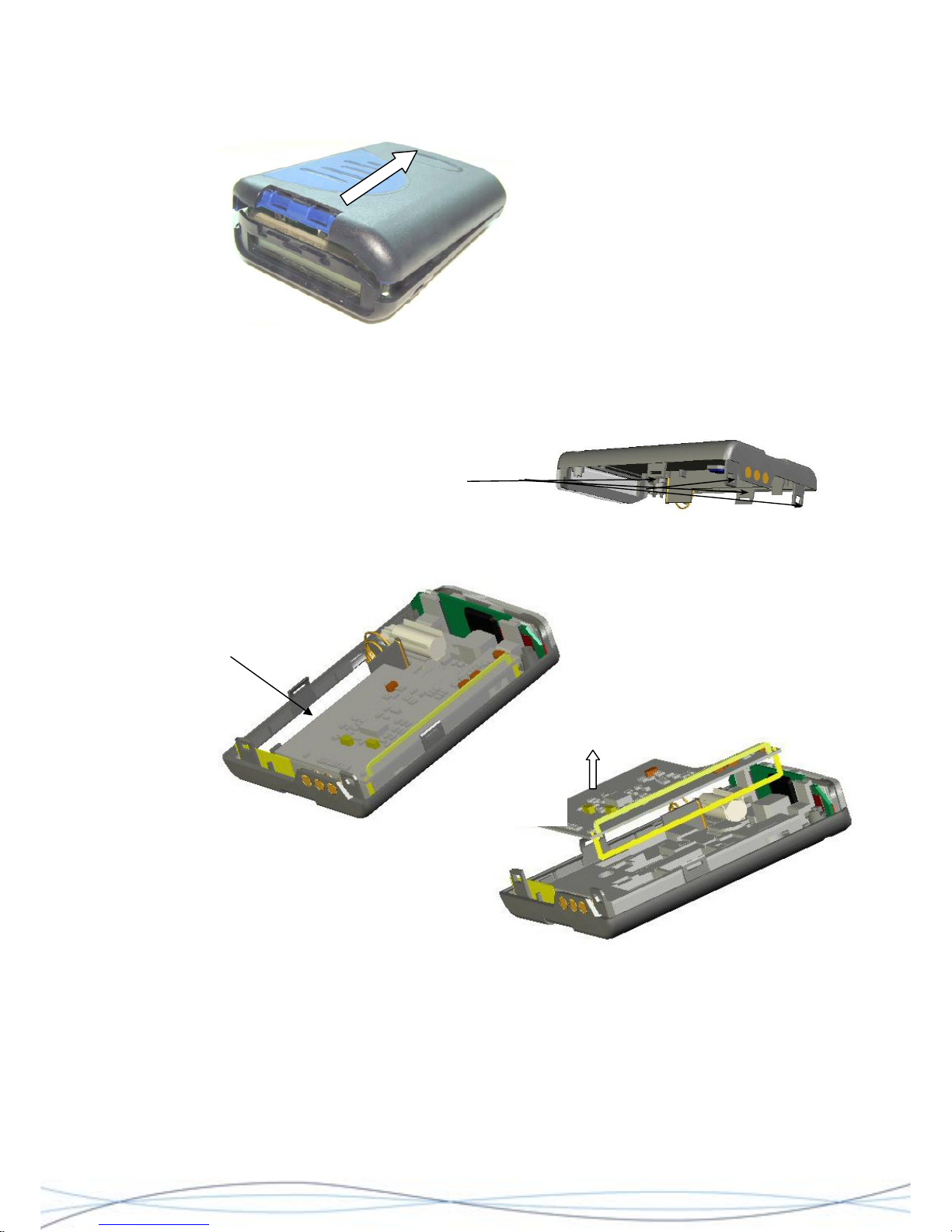
Remove the 2 fixing screws located at the top/rear of the case.
Locate the catch on the outer edge of the battery
compartment. Apply pressure where indicated and
unhook the rear-case tag from the front-case tab and
release. This will separate this edge of the front and rear
case halves.
Separate the two
case halves and
push here whilst pulling apart. At the same time, apply
pressure to the side of the case back as shown to the left, to
release the tag & tab inside.
30
Page 34
TM1215 Iss. 6.0 RPR750
Separate the two case halves around the
area of the catches. Holding the rear half
of the pager in one hand, with the other hand, grip and gently pivot the case front
upwards. This should release the remaining 2 catches. Take care not to strain the speaker
connection. Using tweezers or fine pliers, unplug the loudspeaker connector from the
decoder PCB and put the case front assembly aside.
Location of "locking" catches on case-rear moulding
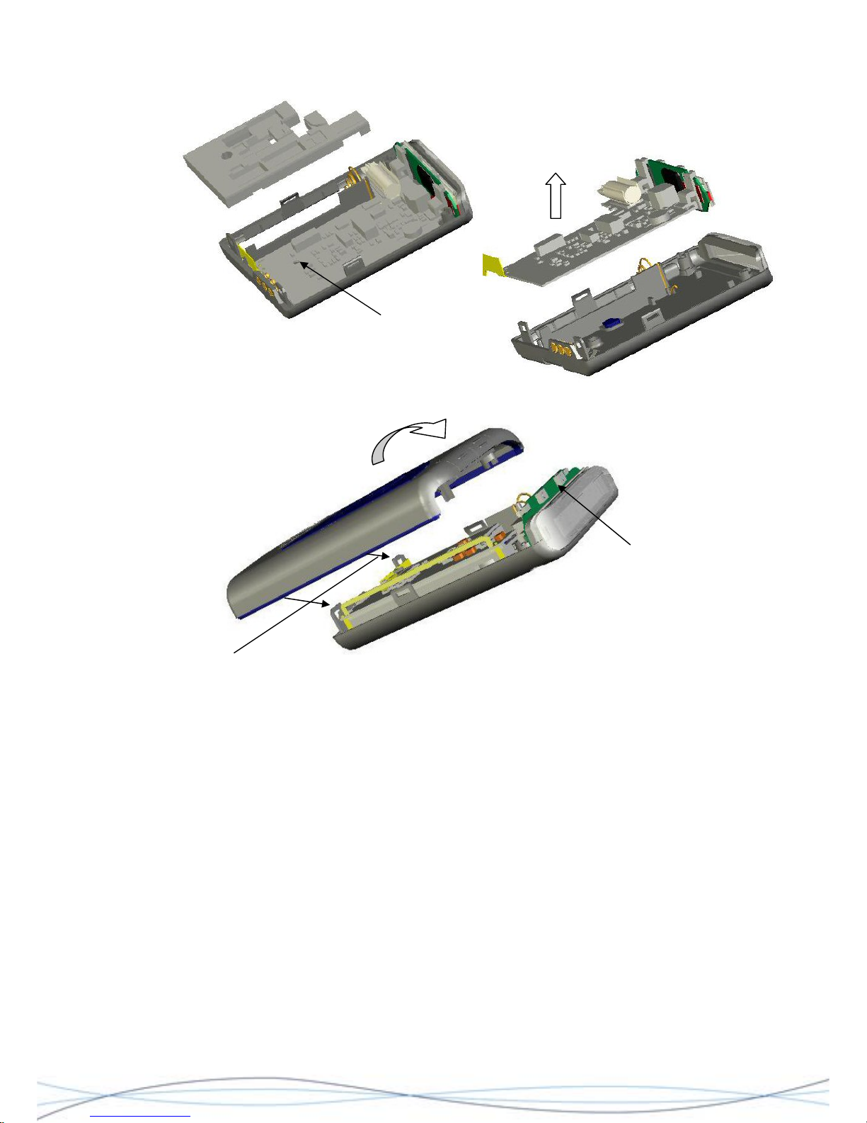
4.4.3 PCB Separation
NOTE: PCB profiles are illustrative only and may vary for each model of the RPR 750.
Lift here
To remove the radio PCB, gently lever-up the edge of the board at the point shown. This
will release the PCB assembly from the socket on the decoder PCB. Lift the PCB (taking
care not to damage the aerial loop) away from the housing.
To remove the decoder/display assembly from the case, firstly remove the rubber PCB
spacer. Remove the M2 retaining screw located where shown, using a cross-head (Pozi)
screwdriver. This will release the assembly, which may then be lifted from the housing.
31
Page 35
TM1215 Iss. 6.0 RPR750
Location of retaining screw
4.4.4 Re-assembly
Ensure that the
switches are located
correctly, before
closing.
Locate these rear catches first
Re-assembly is the reverse process of the above. When re-assembling a complete caseback assembly (including PCB's) together with a case-front; first locate the two catches at
the base of the rear case assembly and lock these into position in the case-front.
Ensure that the edges of the case are correctly aligned and working up from the base
along both edges, squeeze the sides into position, ensuring that the locking catches
engage. Before closing the top, check that the switches on the display module engage
correctly behind the buttons in the front case moulding and that the display module sits
correctly in front of the loudspeaker-retaining clip. Gently squeeze the top halves of the
case together until they join. Screw the two halves together, using the 2 fixing screws.
To re-fit the buttons (early models), first locate each button in position. This is done by
locating the "tab" at the bottom of each button, in the slot at the lower front of each button
recess. Gently push the button back into the recess, ensuring that the two locating lugs on
the back of the button position themselves into the corresponding dovetail notches at the
back of the recesses and the buttons lie flat.
For older models, fit a NEW window part in place over the top of the unit, ensuring it is
pushed down firmly and retains the rear button lugs in place.
32
Page 36
TM1215 Iss. 6.0 RPR750
Before attempting clip replacement, ensure that the grip adjustment slider is set to the top
of the clip and that the metal back-plate has been straightened. Re-insert the metal clipback into the guides on the case-back and slowly slide the clip into place, ensuring that
the retaining lug re-locates into the slot in the case-back.
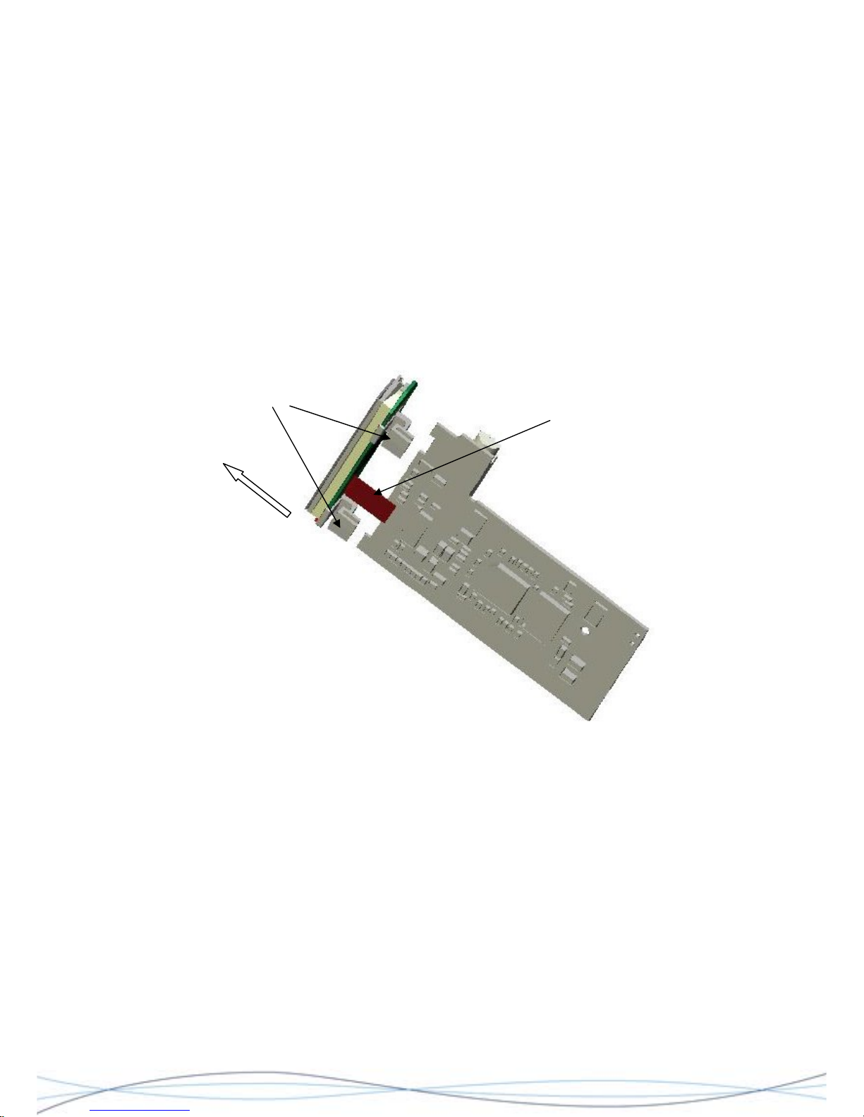
4.4.5 Display Removal
This whole assembly should be treated as a non-serviceable item, to be replaced in its
entirety.
The display module is held in place onto the decoder PCB, by two plastic clips. To remove
the display, hold the decoder PCB assembly in one hand and grip the edges of the
"release bar" on the flexible connecting strip connector, between your finger and thumb.
Pull the bar towards the display module until it "clicks", to release the connecting strip.
Grip and pull the display assembly away from the decoder PCB.
Grip display
assembly and
pull away from
decoder
Flexible connecting strip
Retaining clips
4.5 Servicing Information for the Decoder PCB’s 0261-7498 (MKI) & 0261-8243 (MKII)
The following information is intended to enable a series of front-line diagnostic tests on the
Decoder PCB, in order to establish the possible area at fault and whether a field-repair is
possible. Basic fault-finding information has been provided on the most common faults,
categorised by how the fault has been observed.
Please refer to the circuit and layout diagrams in Section 7.
4.5.1 Test Arrangement
It may be possible to check the Decoder PCB whilst it is still fitted to the rear-case
assembly and using the receiver's AA battery, but where it is necessary to remove the
PCB for access (see section 5.4.3), then separate power supply arrangements must be
made. Care should be taken not to damage the PCB contact areas, when making such
connections.
33
Page 37
TM1215 Iss. 6.0 RPR750
4.5.2 Test Equipment
1.5V nominal dc power source
Digital Multimeter
Oscilloscope
Test Encoder (P645)
RF Signal Generator
Multitone P648 Programming Unit
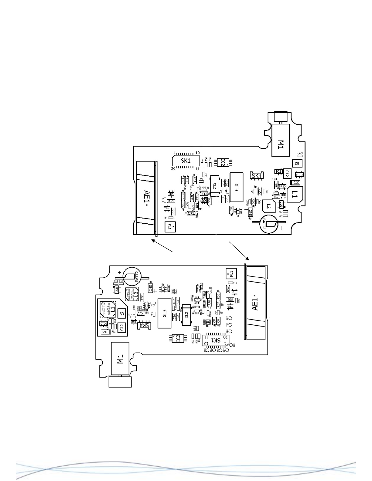
4.5.3 Component Location Points
MKI Decoder 0261-7498 Topside
HF Variants only
MKII Decoder 0261-8243 Topside
34
Page 38
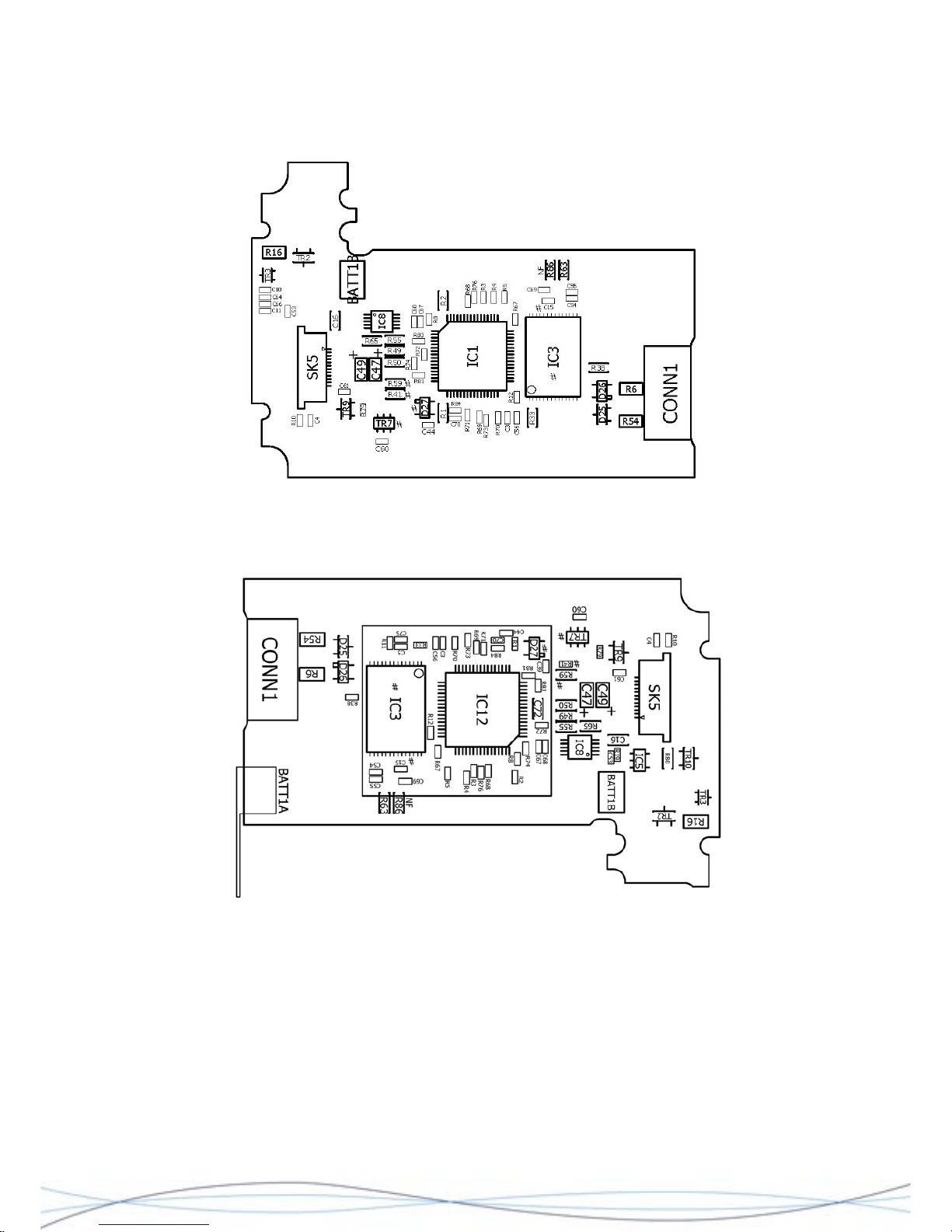
TM1215 Iss. 6.0 RPR750
MKI Decoder 0261-7498 Underside
MKII Decoder 0261-8243 Underside
4.5.4 Basic Test Measurements
1. 3.3V ±5% should be present on the positive end of C12.
Fault condition found - check the operation of the voltage converter IC10, the series
inductor L1, or the rectifier diode D29. With a 'scope probe on IC10 Pin 1, check for the
converter oscillating; a short circuit on the 3.3V rail would prevent this from working.
2. 3.3V ±5% should be present on the Source pin of TR10.
Fault condition found - check the "battery detect" circuit, TR8, R10 & C62, or for a short
circuit elsewhere on the 3.3V supply rail.
35
Page 39

TM1215 Iss. 6.0 RPR750
3. Check that the reset line is high i.e. the supply rail is within limits and the microprocessor is operational.
Fault condition found - check IC5 pin 1, or the junction of C16 & R19. If the reset line is
low, then the 3.3V line may be outside limits, IC 5 may be faulty, or there could be a short
circuit elsewhere on the line.
4. Check that the backup cell BATT2 is being charged. On BATT+ terminal, there should
be 3.3V ±10% (this may vary between 0V and 3.3V on a new decoder, as it may take up
to 24 hours for BATT2 to be fully charged).
Fault condition found - check R17, or BATT2.
5. Check that the micro-processor clock crystal is oscillating and the frequency is
4.194MHz ±0.01%.
Note - this measurement should be made within a few seconds of powering-on the
decoder, as once the initialisation sequence is complete, the decoder will start to use the
STOP mode and the main oscillator will be switched off for most of the time.
6. Check that the micro-processor sub-system oscillator (XL2) is running @ the correct
frequency, either 32.768kHz for 512 Baud or 38.4kHz for 1200 Baud rate receivers.
Note - this oscillator should run continuously.
4.5.5 Alpha-numeric Display does not work
Check for poor solder joints on R68 - R73, R76 & R81. Check for solder short circuits on
SK5. Change the Liquid Display Module (LCM) for a known good unit. If the display starts
to work, replace the faulty LCM.
4.5.6 Display Backlight does not work
Check that the backlight has not been software inhibited (battery low for example). If not,
measure the voltage on IC1 pin 20, or IC12 pin 39 for the MKII variant, (B/L); when the
light is active, this should be a 3V minimum pk-pk square wave, @ approximately 30kHz.
If the correct driving waveform is present on IC1 pin 22 (IC12 pin 41), check R79, TR9,
L2, or the backlight LED on the LCM module.
4.5.7 Decoder does not "Beep"
For test purposes, the Beep signal may be activated either during the switch-on
initialisation, or when the mute button is pressed to determine the pager status. First
check that the loudspeaker is connected and there are no shorts on SK4.The beep signal
should be measured on IC1 pin 21, or IC12 pin 40 and is typically a 2.7kHz square wave.
If the signal is not present, then there is a solder short, a fault in IC1/IC12, or the beep
output is inhibited in the software, as the result of an EEPROM option.
If the O/P from IC1/IC12 is present, measure the supply voltage to the audio amplifier (IC8
pin 10) and check that the amplifier is enabled (IC8 pin 2 = 0V). If not, fault lies with IC8,
or IC11.
4.5.8 Decoder Vibrate Motor does not operate
1). Check that the vibrate-motor signal O/P from IC1 pin 12 or IC12 pin 57 is @ 3V, when
the motor should be active. 2). Check that TR3, R16 and TR2 are functioning correctly.
3). Check the vibrate motor itself is working.
36
Page 40

TM1215 Iss. 6.0 RPR750
4.5.9 Decoder Alert LED not working
If the LED does not work when the pager is inserted into a charging rack, then check D25,
R52, R54 and the LED itself.
If the LED is not operable during the initialisation sequence, or when the pager receives a
call, verify that IC1 pin 22 or IC12 pin 41(HS) switches to 0V when the LED is active. Also
check the circuit around TR6 and R53.
4.5.10 Decoder does not call
Check that the decoder is enabling the radio via SK1 pin 13 (RXEN) (radio is enabled by
DATAP being set to 3V3). Recovered data should be present on SK1 pin 11 (DATAP).
Using the RF signal generator and a call encoder, send continuous pre-amble to the
pager. Check that the radio is enabled and that the mark-space ratio of the recovered data
is 50:50. If not, check that the fast charge signal (F_CHG, SK1 pin 12) is activated, as the
decoder first samples the data.
If the decoder is receiving continuous pre-amble with a consistent 50:50 mark-space ratio
but will still not call, check the programming of the EEPROM (IC2).
4.5.11 Decoder does not receive Speech Calls
Check that the pager is programmed to receive speech calls and that the loudspeaker is
connected correctly (SK4) and not faulty.
Verify that when a speech call is received, the alert sequence is a maximum of 4 seconds
duration and that there is no escalating alert. When the alert sequence is complete, check
that IC9 pin 5 (EN2) and IC8 pin 2 (EN1) are both set to 3V3. This enables both the
speech pre-amplifier and power amplifier.
Check the speech signal path from SK1 pin 9 (RX_AUDIO), through IC9 (pin 4) and IC8
(pins 7 & 9).
4.5.12 Pager does not record Speech calls
Check for the presence of speech at the junction of C7 & R78. Confirm that the relevant
control signals are present on the speech chip (IC3 pins 8, 9, 10 & 11) and that the
speech signal is present on IC3 pin 20 (AUDOUT) when speech is played back, indicating
that the speech chip is recording correctly. If a speech signal is present, check C6, C43,
R57 and IC8 plus associated circuitry.
4.5.13 Pager cannot be programmed
Confirm that the pager displays entry into the absence/programming, by displaying the
"rack" message programmed into IC2. Verify that the waveform on the programming pin
(PROG) is correct. Typically, the programming input is held low for 18ms, switched high
for 2ms and then returns low. This indicates that the pager has detected the presence of
the rack/programmer and is waiting for a transaction. If the waveform is not present, check
R6, R38, or the programming contact.
If the pager enters absence/programming mode, but does not programme consistently,
check that XL3 is the correct frequency (4.194304MHz).
If the pager responds correctly to the absence/programming commands, but does not
store the data, check the decoder EEPROM (IC2), R9, R75 & R77.
37
Page 41
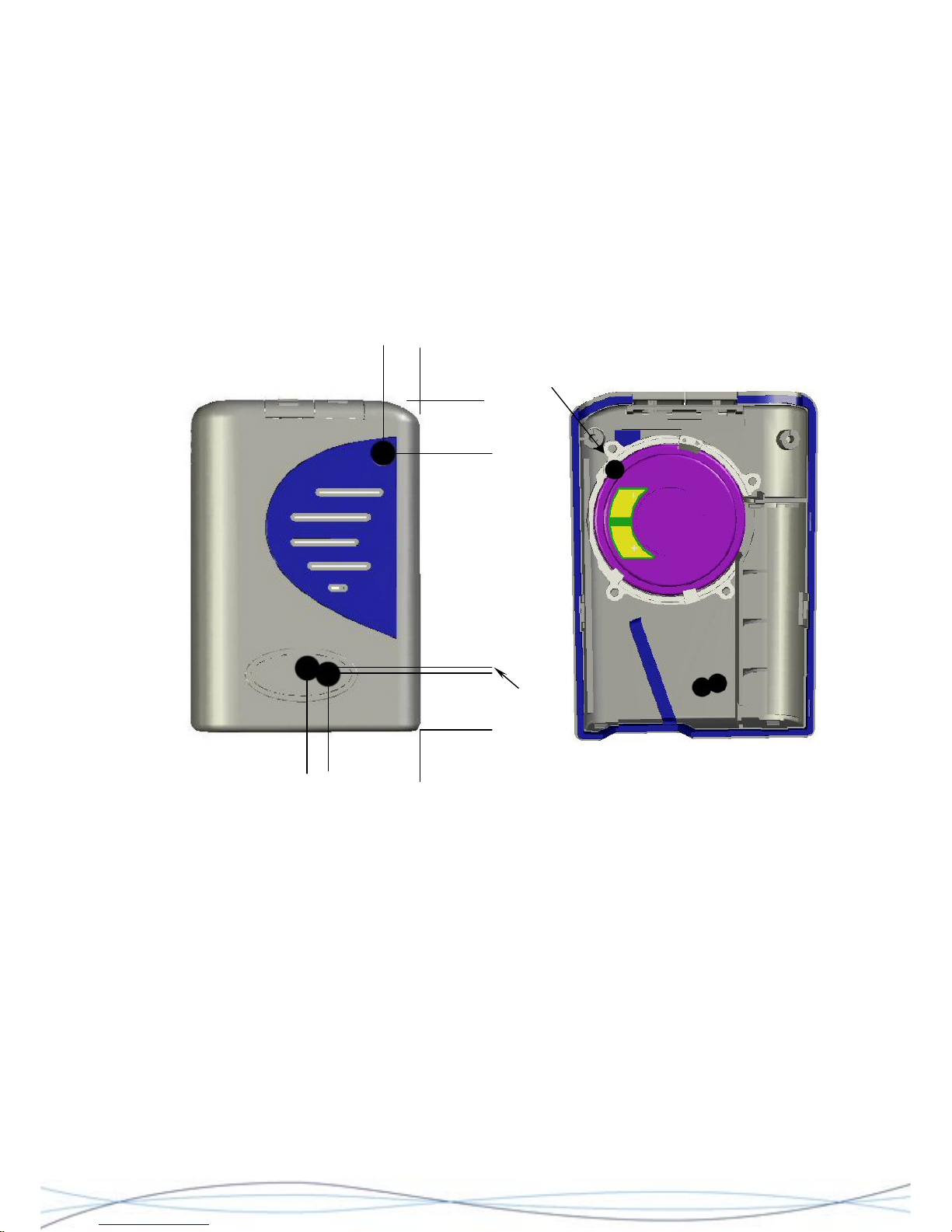
TM1215 Iss. 6.0 RPR750
4.5.14 Pager Clock is inaccurate
Check that the correct crystal (XL2) is fitted for the code format used. Confirm that the
frequency is within limits. If not, check C1 & C2 and replace the crystal if necessary.
4.6 Alignment of VHF & UHF Radio PCB's
It is possible to perform a rudimentary radio PCB alignment, outside of the case assembly.
However for final tuning of the aerial, it is necessary to use either a Multitone alignment
jig, or a modified case assembly, which has the necessary cut-outs for access to the
alignment points.
Hole through
loudspeaker
5 25
13
14
18
10
Dimensions are shown in millimetres and are approximate.
Diagrams showing hole positions for tuning points on a "dummy" case -front. The
suggested drilled hole diameter is 6 - 6.5mm. N.B. It is essential to retain the
loudspeaker on the inside of the case, as its metal construction forms an intrinsic
part of the circuit conditions, when fine-tuning the aerial. It will be necessary to
create a hole through the metal surround of the speaker.
4.6.1 Test Arrangement
In order to align a radio, the PCB will need to be connected to a working decoder PCB &
rear case assembly and the drilled front-case fitted over the radio for final tuning. Power
may be provided by an internal battery, or an external PSU connected to the battery
terminals. Any alignment must be carried out in an area, which is free from external RF
signal interference.
38
Page 42
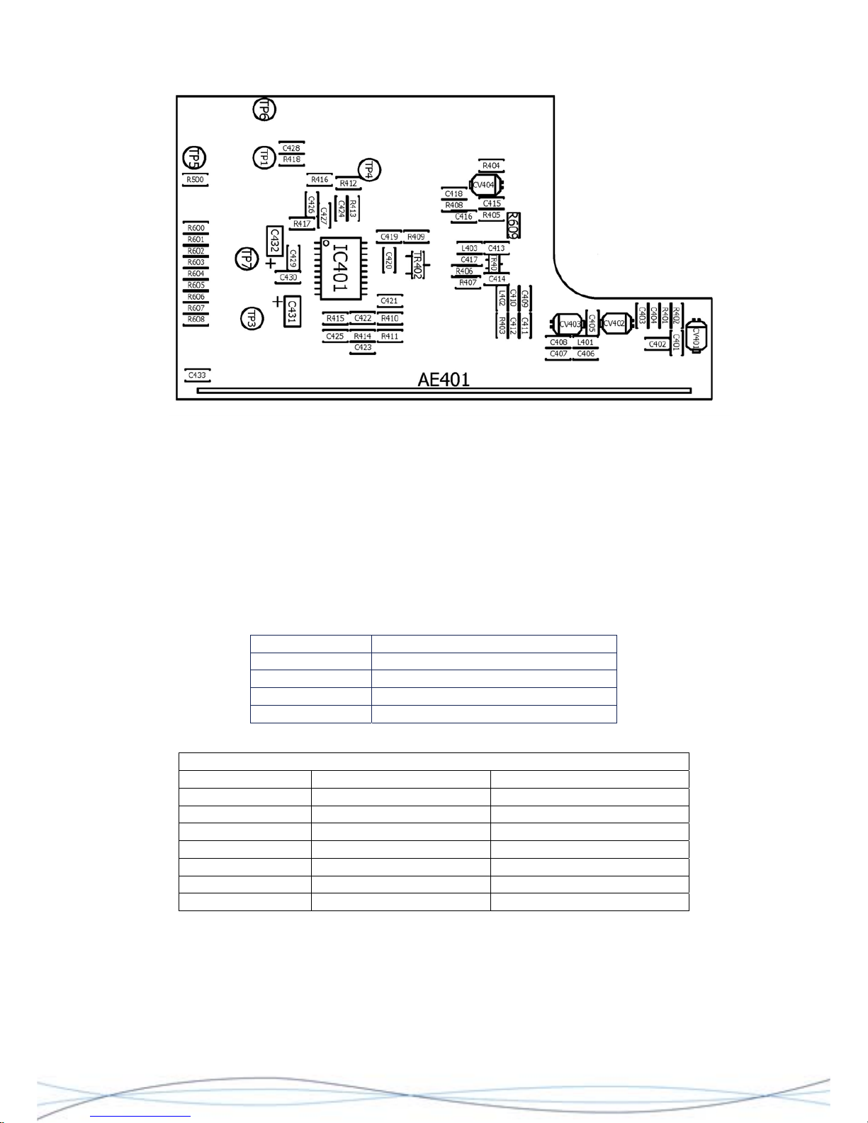
TM1215 Iss. 6.0 RPR750
Layout of VHF/UHF Radio PCB, showing Test Points and Adjustment Trimmers
4.6.2 Test Equipment
RF signal generator, with external FM modulation I/P
SINAD Meter
Digital Multimeter
Ceramic/insulated Bladed Trimming Tool & Probe suitable for audio frequencies
Non-invasive coupling device for RF signal e.g. small telescopic aerial connected to RF
signal generator.
4.6.3 Tuning & Test Points
Tuning Points Description
CV401 Aerial Tuning
CV402 RF Stage/Image Filter Tuning
CV403 RF Stage/Image Filter Tuning
CV404 Fine Frequency Setting
Test Points
Test Point Signal Description
TP1 Audio 30mV Audio O/P
TP2 -
TP3 455kHz IF Signal
TP4 1.0V rail (-0.05/+0.1V) 1V regulated supply
TP5 0V Ground
TP6 Pull-up Rx enable RXEN Receiver Enable
TP7 1.1 - 1.6V dc Battery Positive
4.6.4 Procedure
Set the signal generator to the RF channel frequency and modulate the carrier with the
audio output from the SINAD meter. Set the FM deviation to the appropriate level for the
channel spacing of the PCB under test. Set the RF output to high e.g. +20dBm. Do not fit
the case-front at this stage.
39
Page 43
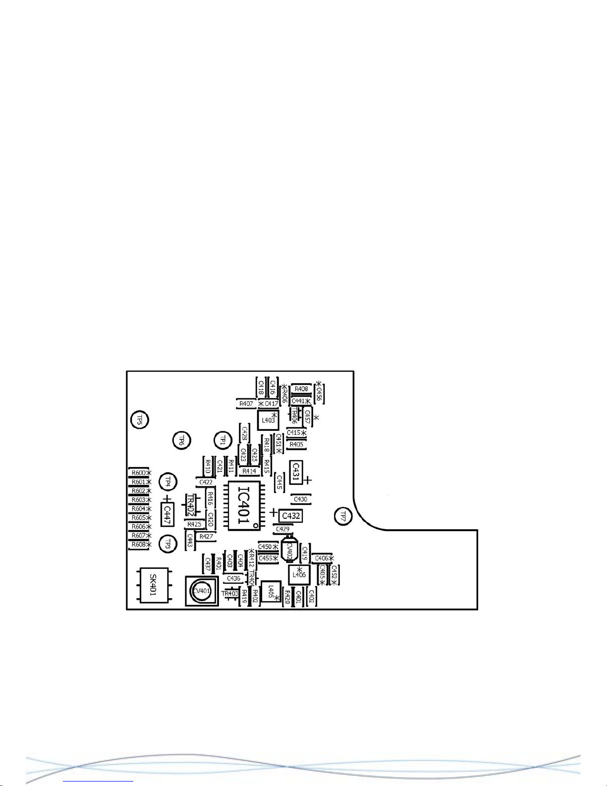
TM1215 Iss. 6.0 RPR750
Starting with the radio PCB uncovered, connect the audio probe from the SINAD meter
between TP1 and Gnd./0V (the circular PCB track next to TP1 is the most suitable point).
Temporarily fit R416 (0R), or connect TP6 to TP7, to enable the receiver. Check the
battery voltage is correct (TP7) and also the 1V rail (TP4).
Adjust CV404 for the best SINAD signal. Reduce the RF output from the signal generator
to a lower level e.g. -60dBm and adjust CV402 and CV 403 for the best SINAD, whilst
further reducing the RF level as necessary.
Fit the case front and adjust CV 401 for best SINAD, gradually reducing the RF signal
level, as necessary.
Remove R416, TP6/TP7 link and any other connections made during this procedure.
Radio alignment is now complete.
4.7 Alignment of HF Radio PCB
4.7.1 Test Arrangement
The HF Radio may be aligned outside of the case assembly, but will need to be
connected to a working HF variant decoder and rear case assembly, with an AE1 ferrite
aerial and PL1 fitted. Power may be provided by the primary battery, or an external PSU
connected to the battery terminals. Any alignment must be done in an area free from
external RF signal interference.
Layout of HF Radio PCB, showing Test Points and Adjustment Trimmers
40
Page 44
TM1215 Iss. 6.0 RPR750
4.7.2 Test Equipment
RF signal generator, with external FM modulation I/P
SINAD Meter
Digital Multimeter
Ceramic/insulated Bladed Trimming Tool & Probe suitable for audio frequencies
Non-invasive coupling device for RF signal e.g. small telescopic aerial connected to RF
signal generator.
4.7.3 Tuning & Test Points
Tuning Points Description
CV401 Aerial Tuning
CV402 RF Stage Amplifier Tuning
Test Points
Test Point Signal Description
TP1 Audio 30mV Audio O/P
TP2 -
TP3 455kHz IF Signal
TP4 1.0V rail (-0.05/+0.1V) 1V regulated supply
TP5 0V Ground
TP6 Pull-up Rx enable RXEN Receiver Enable
TP7 1.1 - 1.6V dc Battery Positive
4.7.4 Procedure
Set the signal generator to the RF channel frequency and modulate the carrier with the
audio output from the SINAD meter. Set the FM deviation to the appropriate level for the
channel spacing of the PCB under test. Set the RF output to high e.g. +20dBm.
Connect the audio probe from the SINAD meter between TP1 and Gnd./0V TP5.
Temporarily fit R416 (0R), or connect TP6 to TP7, to enable the receiver. Check the
battery voltage is correct (TP7) and also the 1V rail (TP4).
Adjust CV401 and CV402 for the best SINAD signal. Reduce the RF output from the
signal generator to a lower level e.g. -60dBm and further adjust CV401/2 for the best
SINAD, whilst further reducing the RF level as necessary.
Remove R416, TP6/TP7 link and any other connections made during this procedure.
Radio alignment is now complete.
41
Page 45

TM1215 Iss. 6.0 RPR750
42
5 List of Diagrams & Drawings
Main Board (Decoder MKI) Circuit Diagram 2961 - 7497-3
Main Board (Decoder MKI) PCB Layout 0261 - 7498-2
Main Board (Decoder MKII) Circuit Diagram 2961 - 8242-2
Main Board (Decoder MKII) PCB Layout 0261 - 8243-3
HF Radio Circuit Diagram 2961 – 7673-9
HF Radio Board PCB Layout 0261 – 7674-3
VHF Radio Circuit Diagram 2961 – 7494-3
UHF Radio Circuit Diagram 2961 – 7834-3
VHF\UHF Radio Board PCB Layout 0261 – 7495-4
Page 46
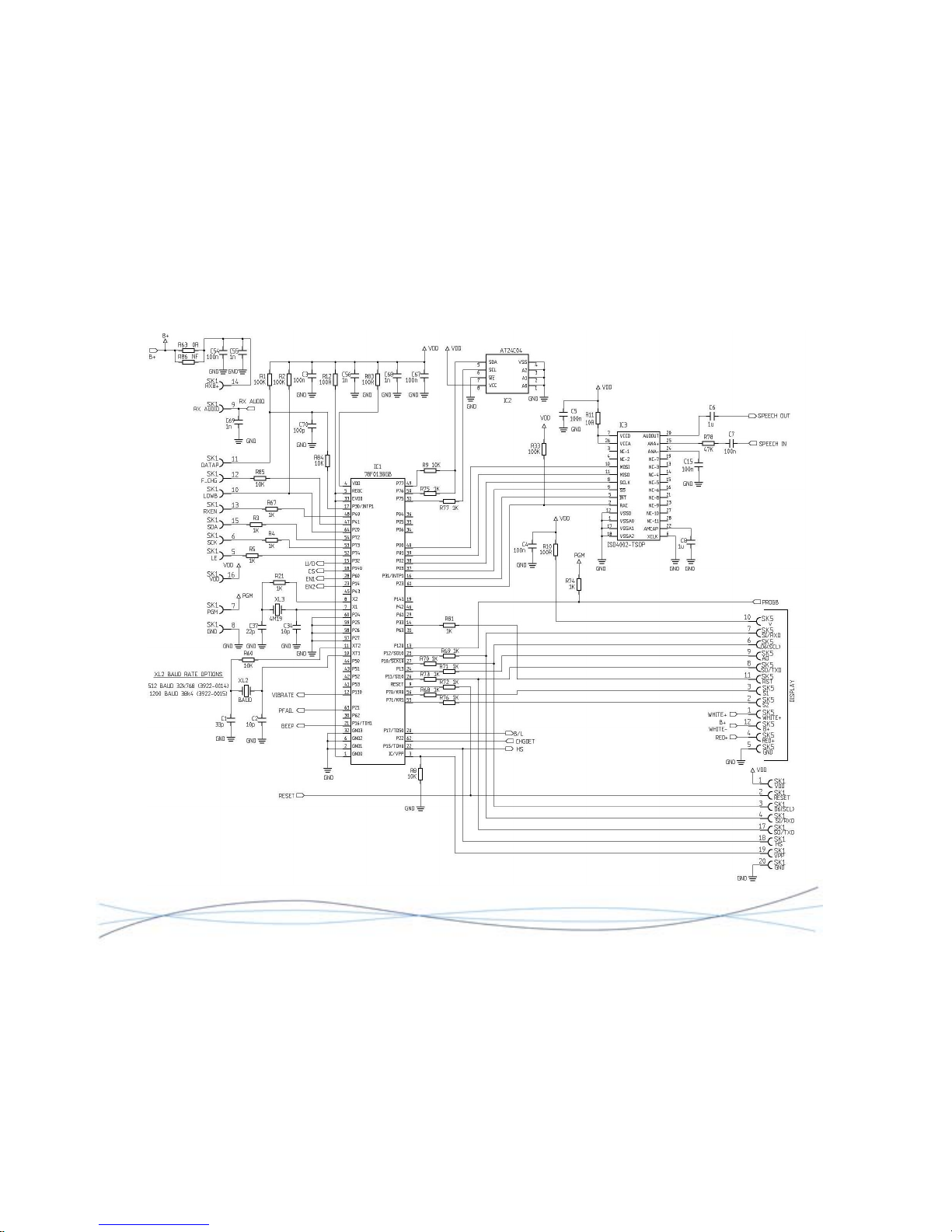
TM1215 Iss. 6.0 RPR750
MKI Decoder Circuit Diagram 2961-7497 Sheet 1
43
Page 47
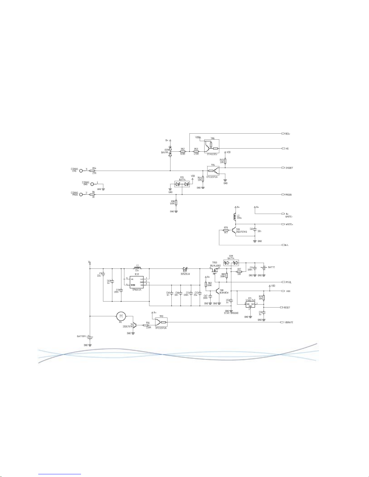
TM1215 Iss. 6.0 RPR750
MKI Decoder Circuit Diagram 2961-7497 Sheet 2
44
Page 48
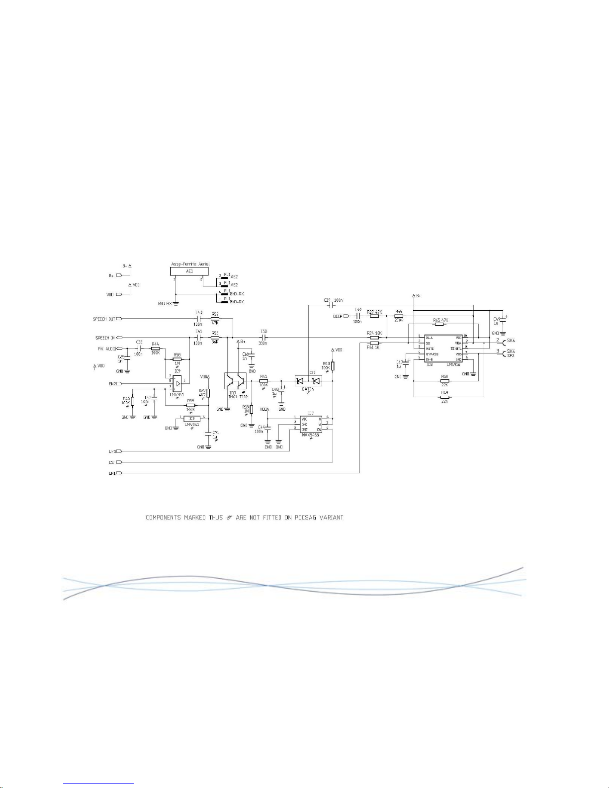
TM1215 Iss. 6.0 RPR750
MKI Decoder Circuit Diagram 2961-7497 Sheet 3
45
Page 49
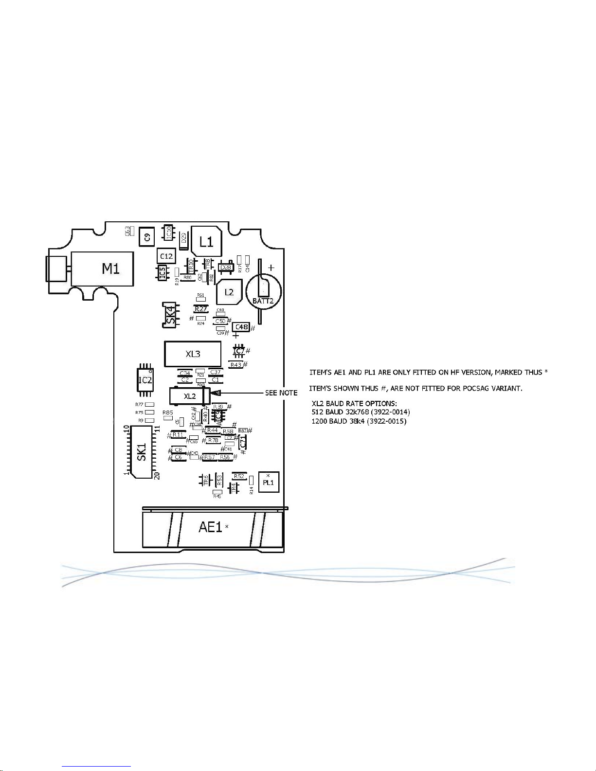
TM1215 Iss. 6.0 RPR750
MKI Decoder PCB Layout 0261-7498 Sheet 1
46
Page 50
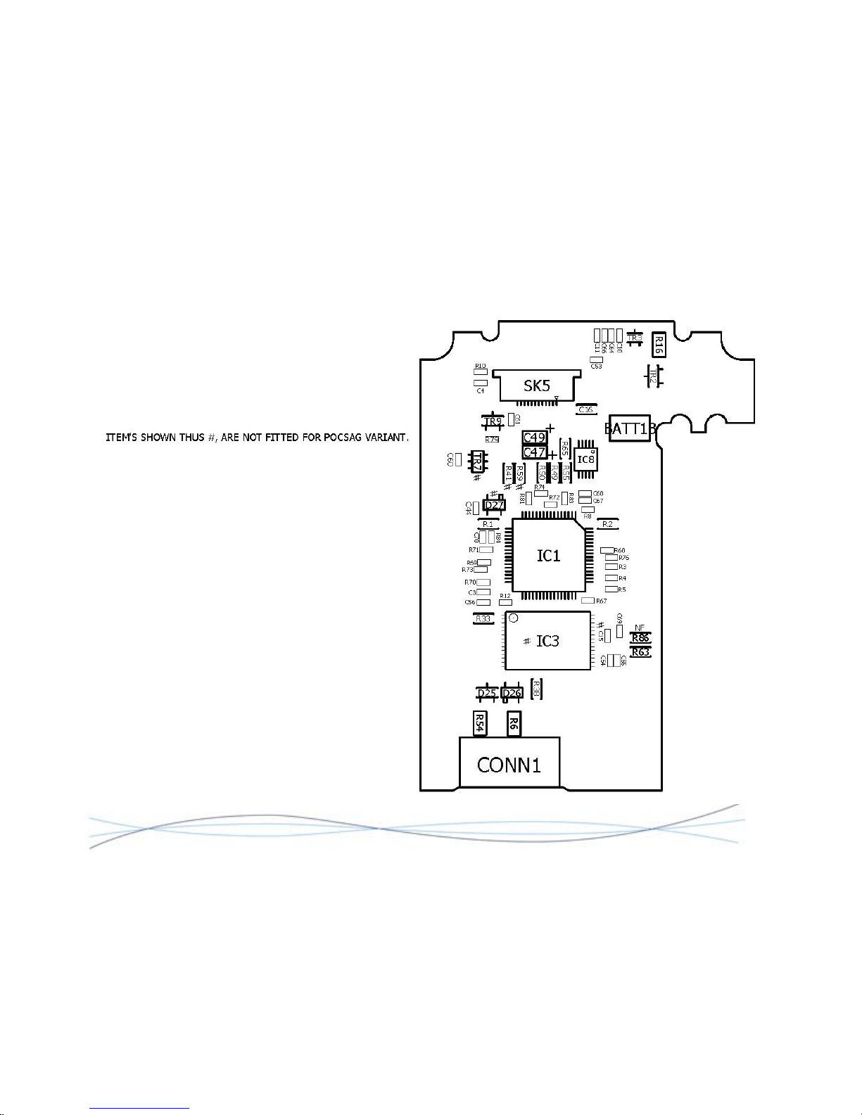
TM1215 Iss. 6.0 RPR750
MKI Decoder PCB Layout 0261-7498 Sheet 2
47
Page 51
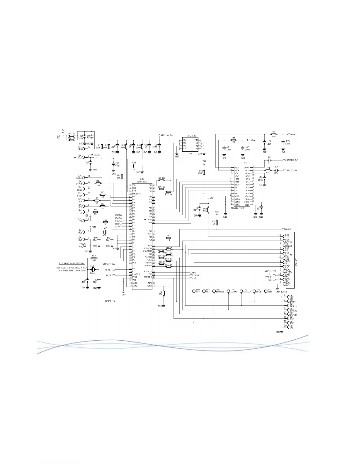
TM1215 Iss. 6.0 RPR750
MKII Decoder Circuit Diagram 2961-8242 Sheet 1
48
Page 52
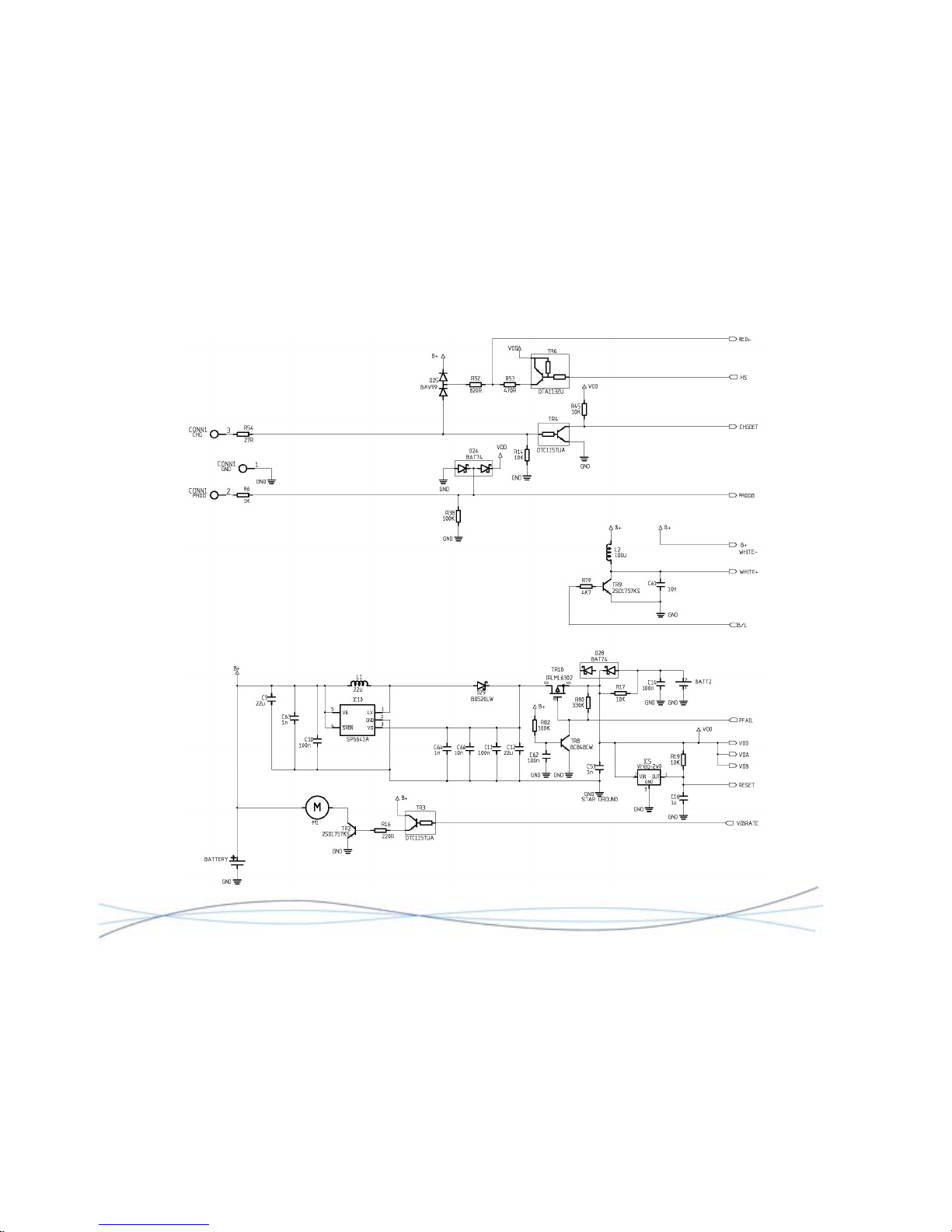
TM1215 Iss. 6.0 RPR750
MK1I Decoder Circuit Diagram 2961-8242 Sheet 2
49
Page 53
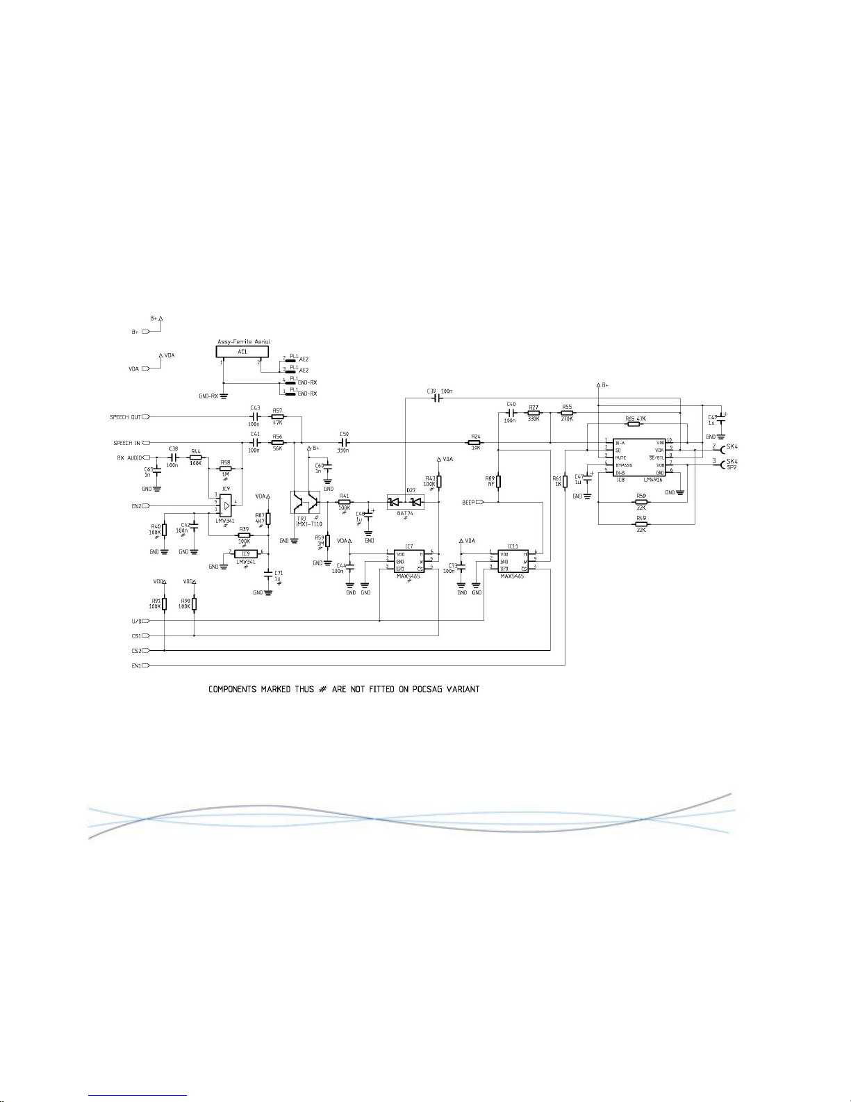
TM1215 Iss. 6.0 RPR750
MKII Decoder Circuit Diagram 2961-8242 Sheet 3
50
Page 54
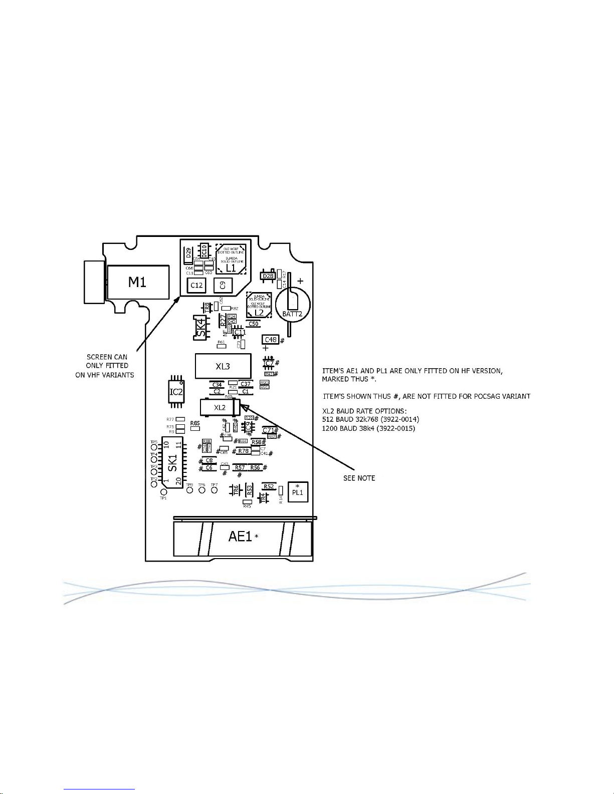
TM1215 Iss. 6.0 RPR750
MKII Decoder PCB Layout 0261-8243 Sheet 1
51
Page 55
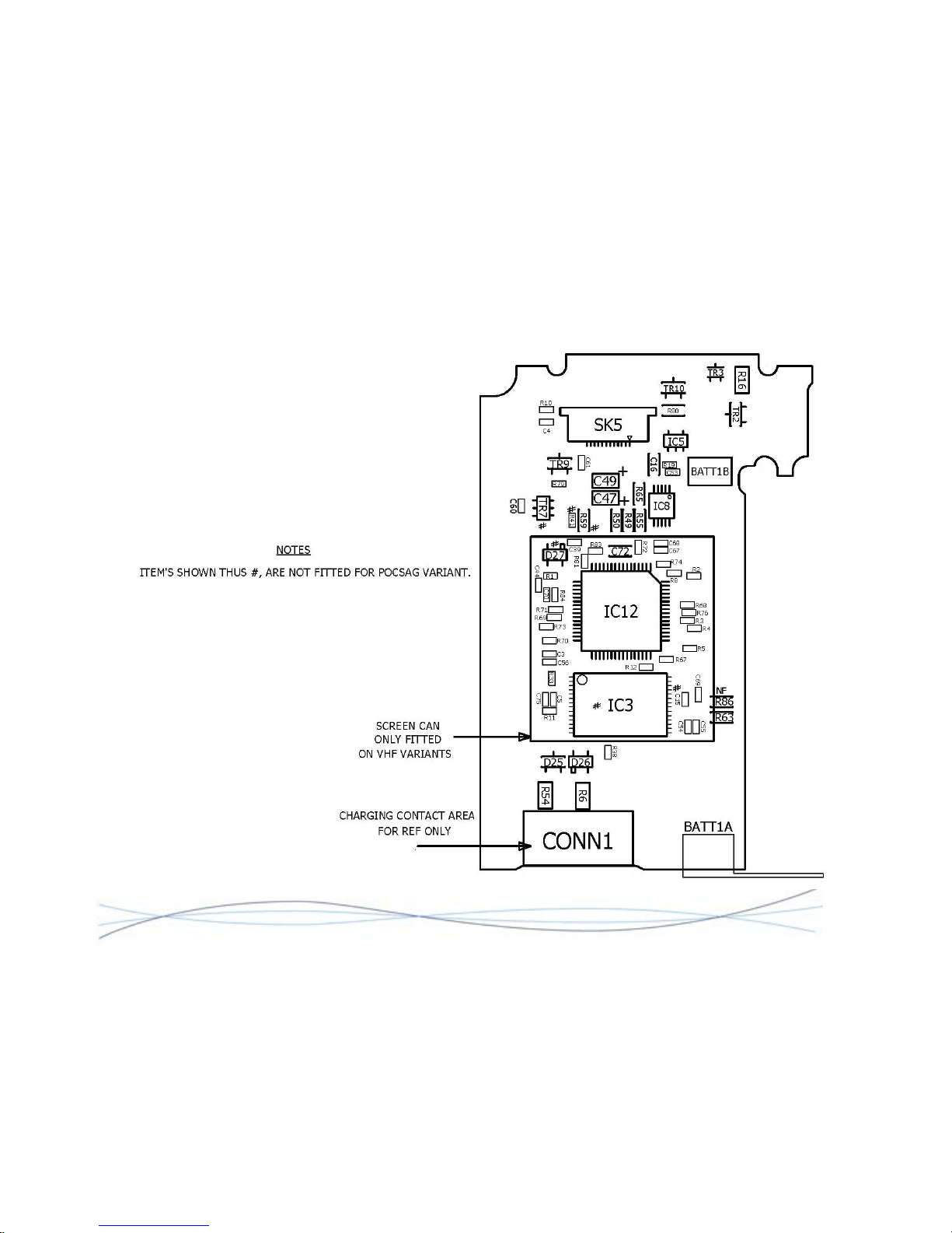
TM1215 Iss. 6.0 RPR750
MKII Decoder PCB Layout 0261-8243 Sheet 2
52
Page 56
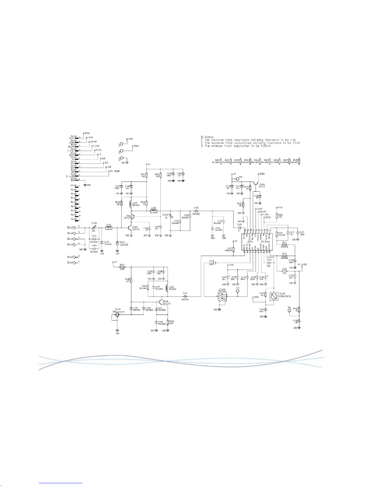
TM1215 Iss. 6.0 RPR750
HF Radio Circuit Diagram 2961-7673 Sheet 1
53
Page 57
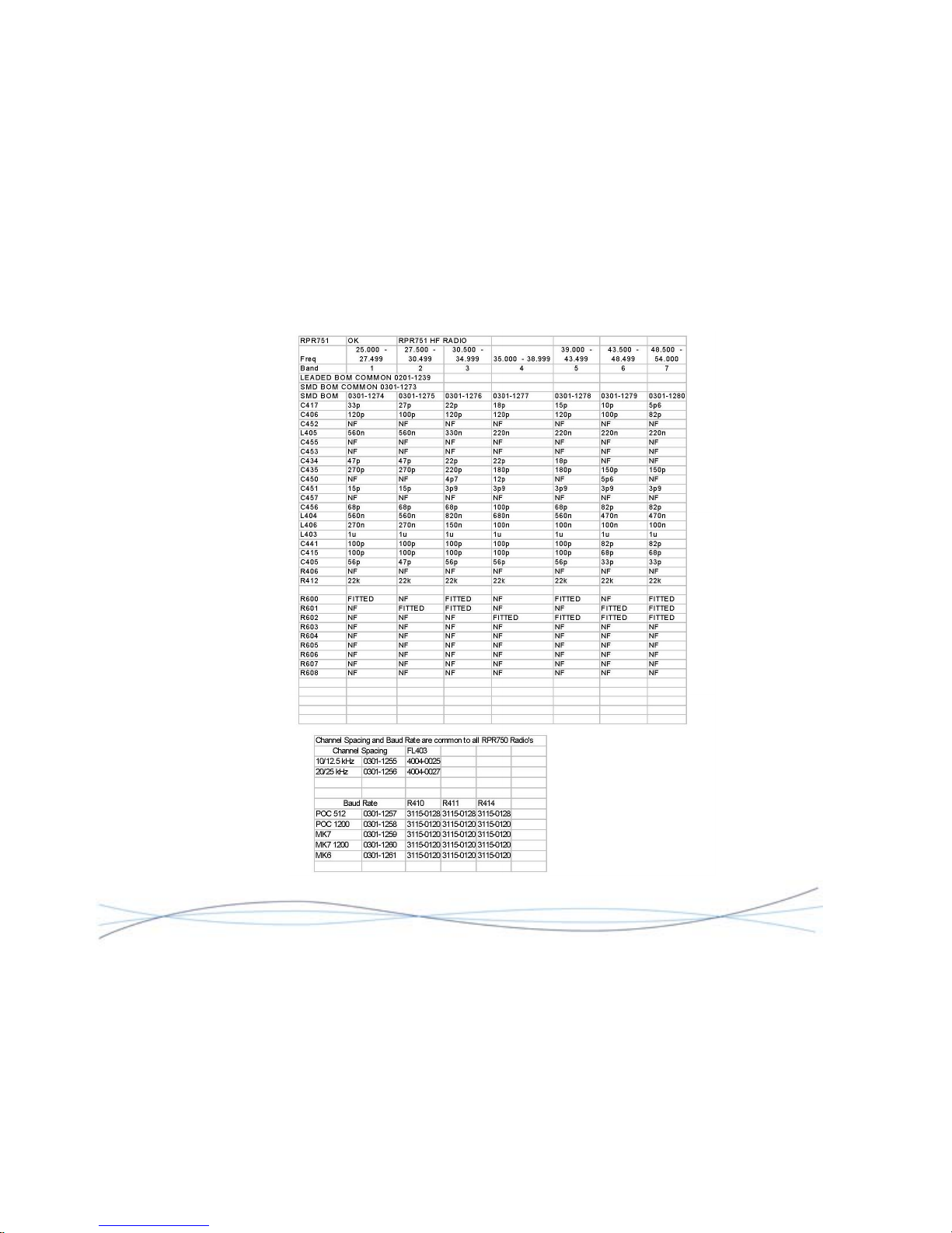
TM1215 Iss. 6.0 RPR750
HF Radio Circuit Diagram 2961-7673 Sheet 2
54
Page 58
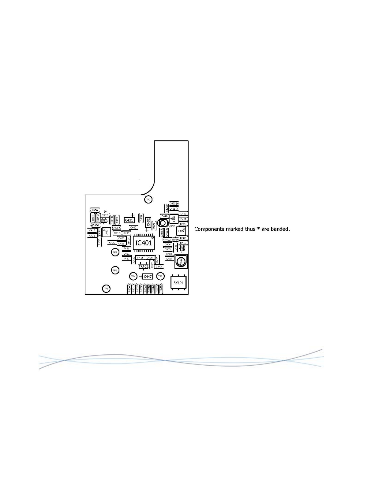
TM1215 Iss. 6.0 RPR750
HF Radio PCB Layout 0261-7674 Sheet 1
55
Page 59
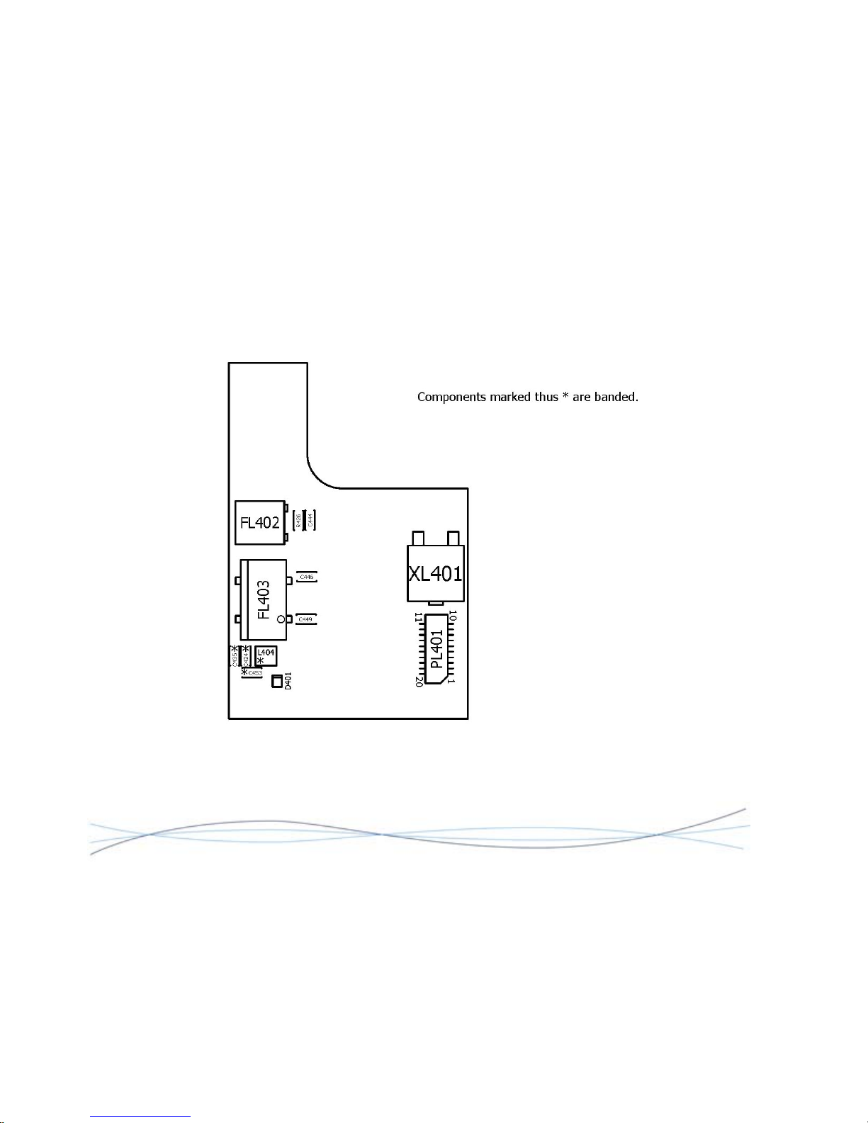
TM1215 Iss. 6.0 RPR750
HF Radio PCB Layout 0261-7674 Sheet 2
56
Page 60
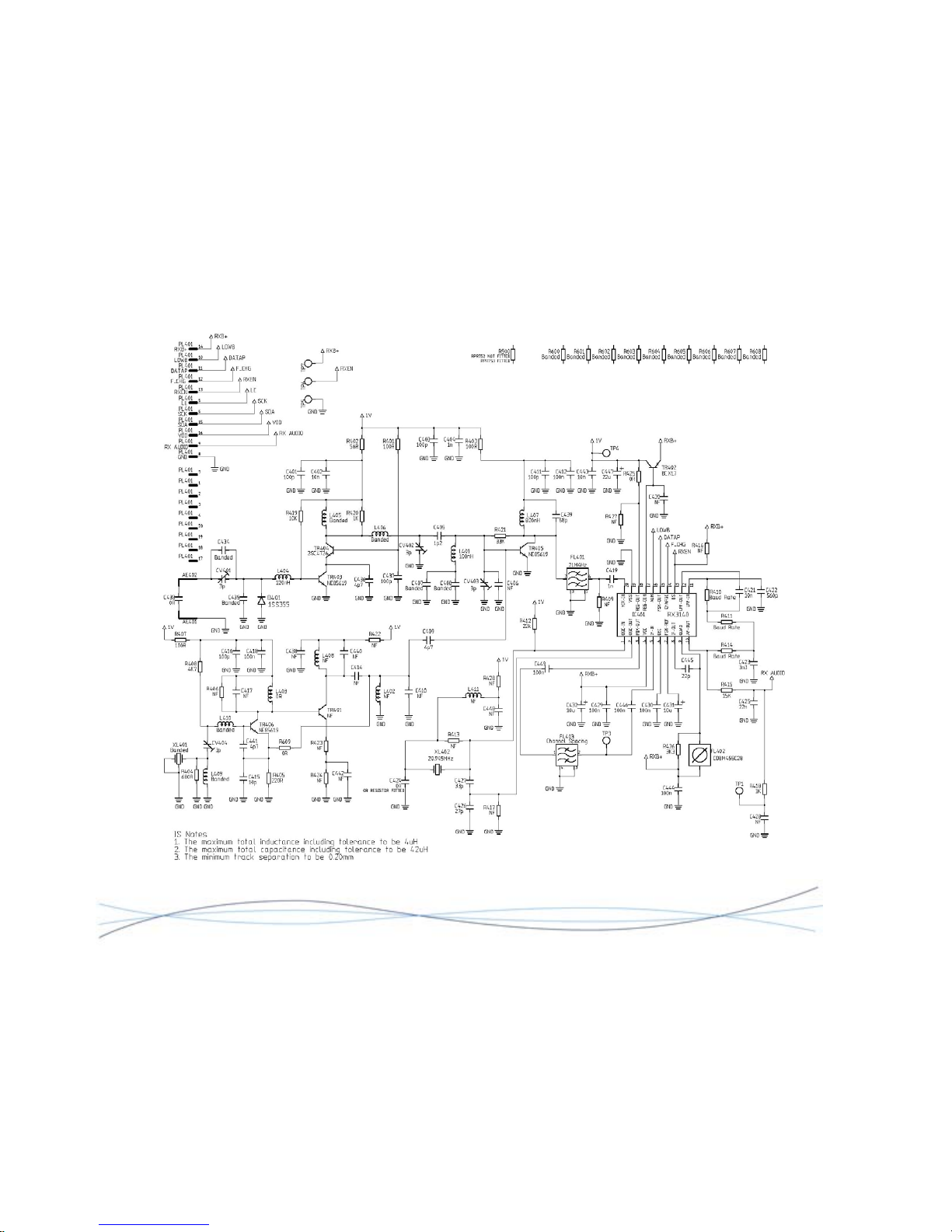
TM1215 Iss. 6.0 RPR750
VHF Radio Circuit Diagram 2961-7494 Sheet 1
57
Page 61
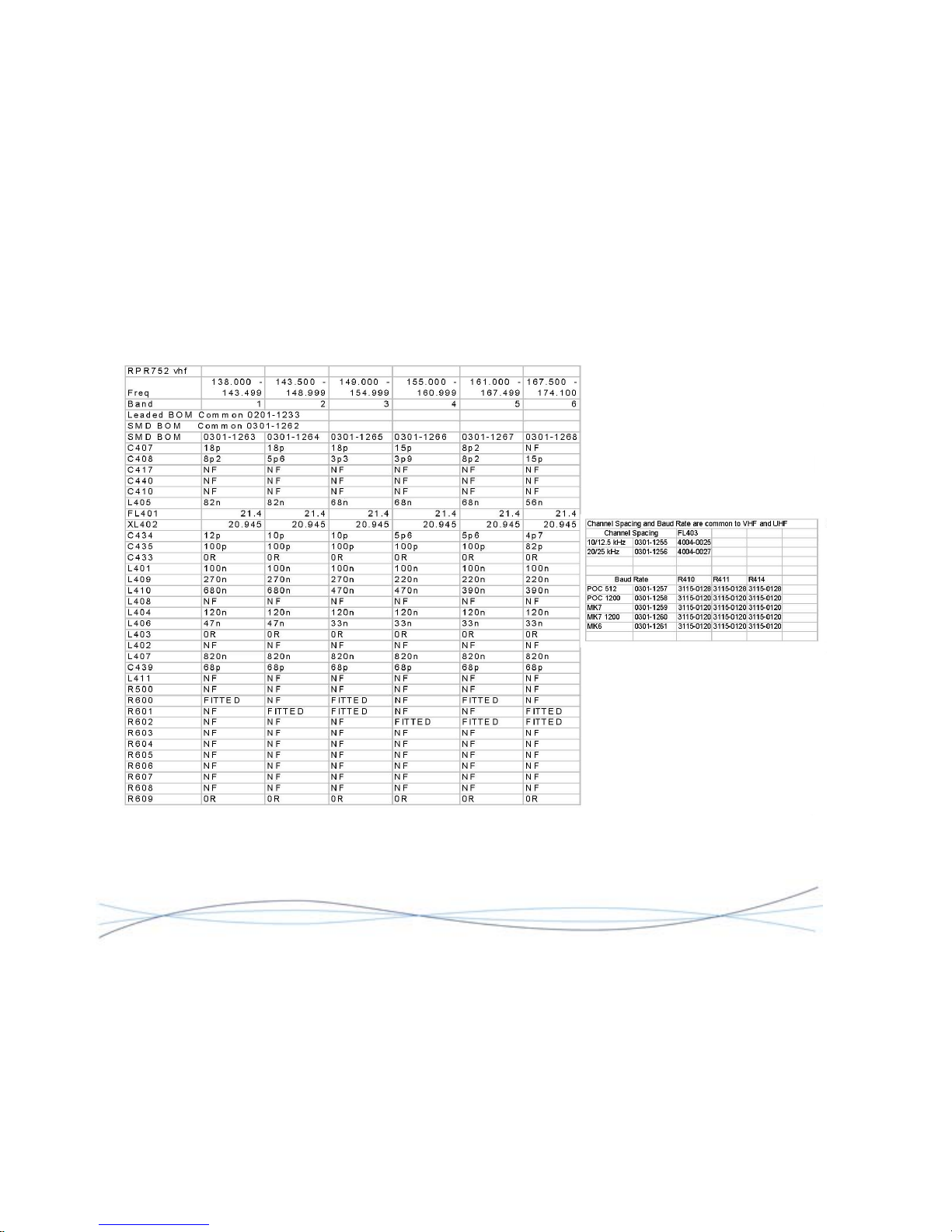
TM1215 Iss. 6.0 RPR750
VHF Radio Circuit Diagram 2961-7494 Sheet 2
58
Page 62
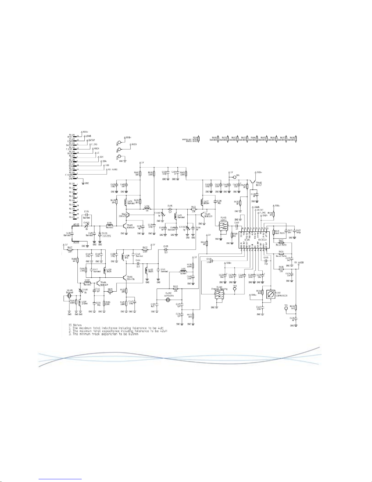
TM1215 Iss. 6.0 RPR750
UHF Radio Circuit Diagram 2961-7834 Sheet 1
59
Page 63
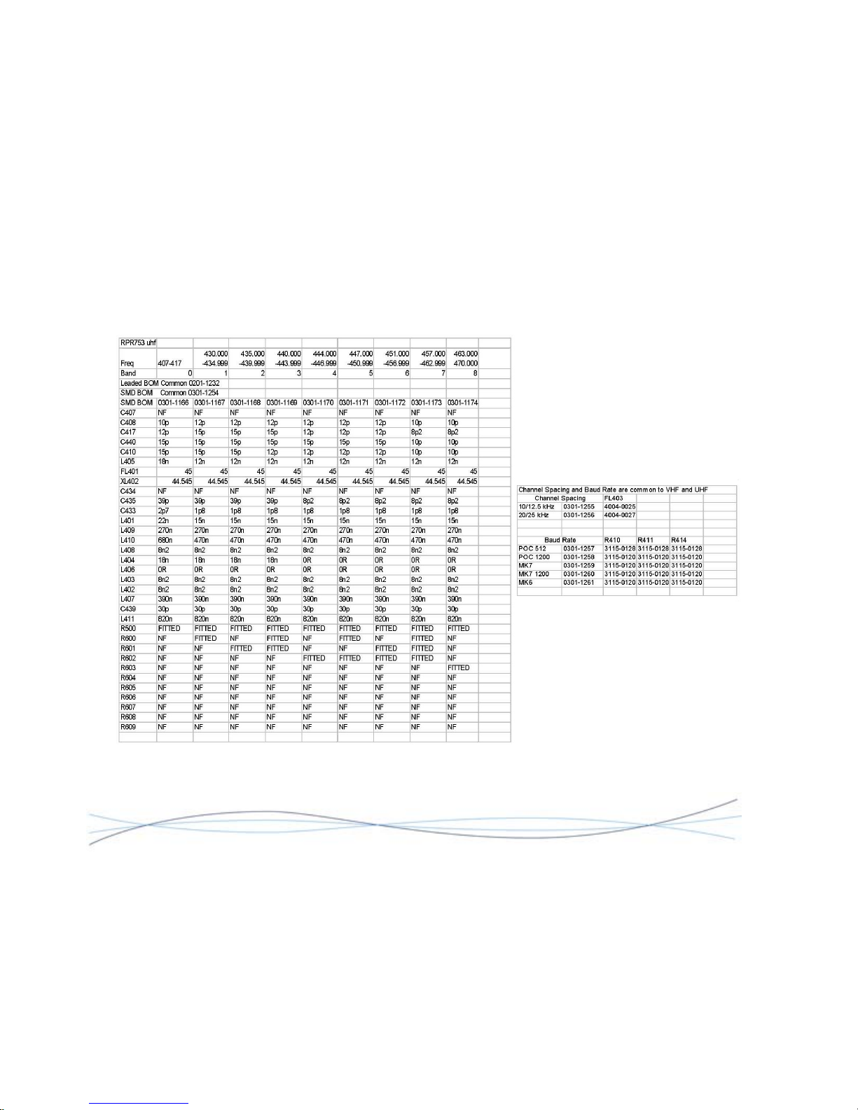
TM1215 Iss. 6.0 RPR750
UHF Radio Circuit Diagram 2961-7834 Sheet 2
60
Page 64
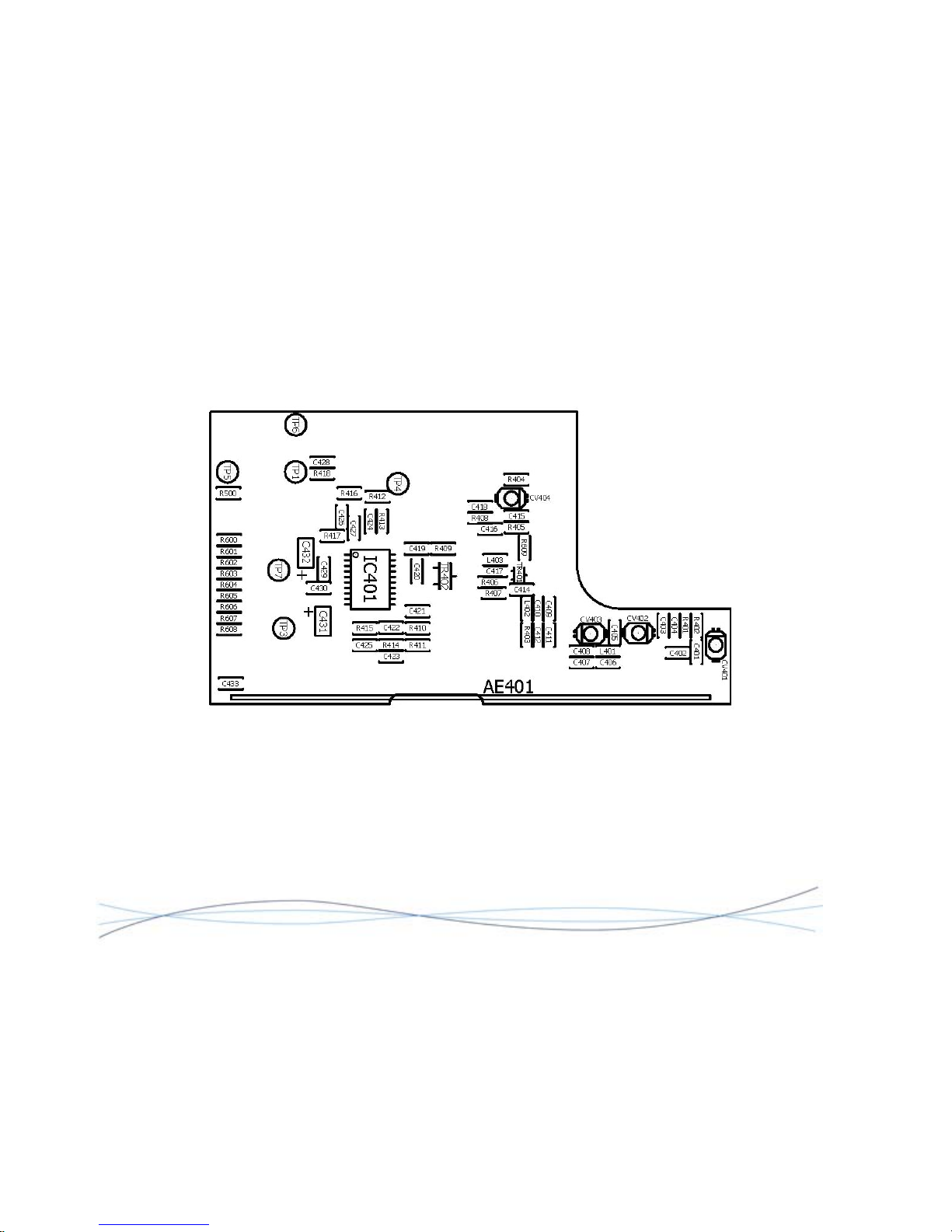
TM1215 Iss. 6.0 RPR750
VHF/UHF Radio PCB Layout 0261-7495 Sheet 1
61
Page 65
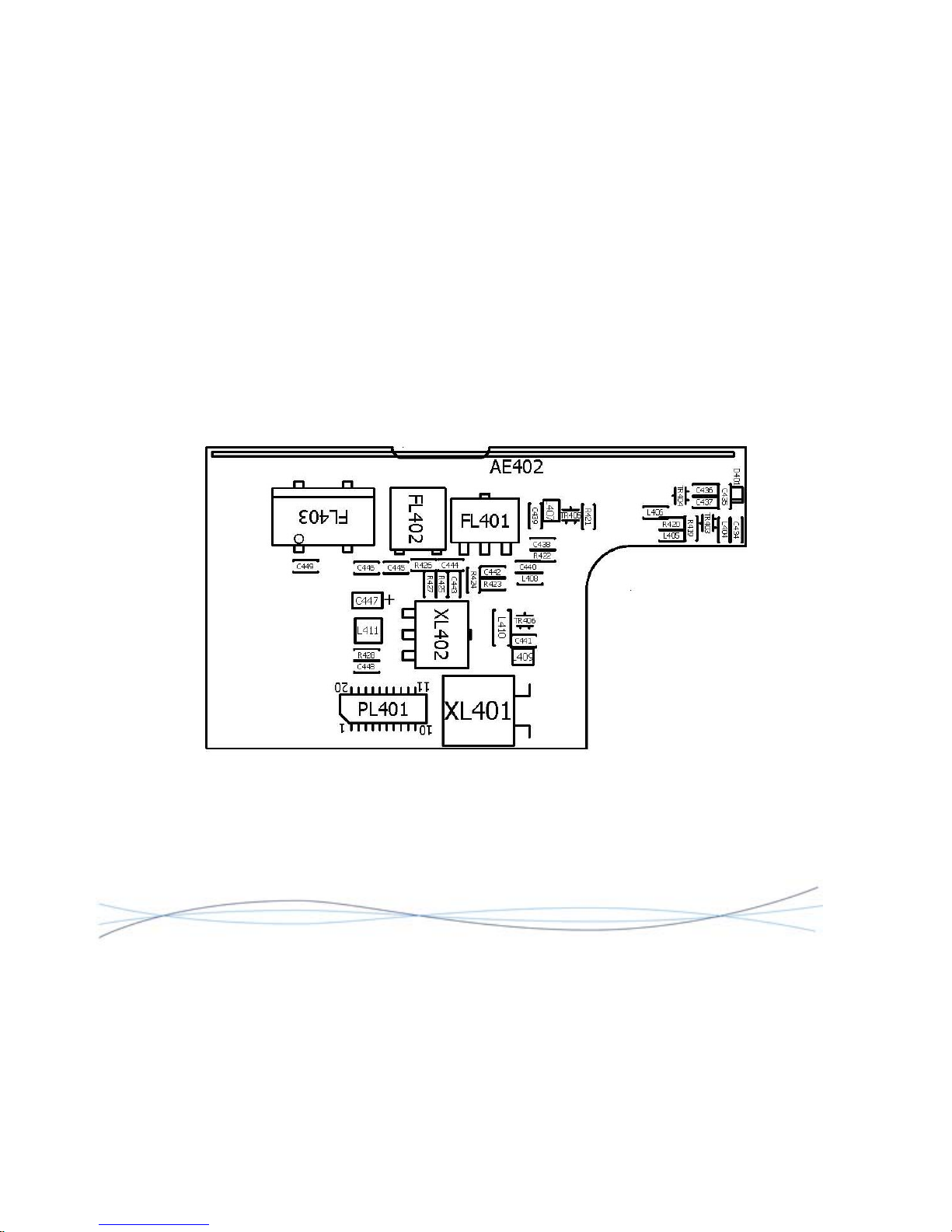
RPR750
62
VHF/UHF Radio PCB Layout 0261-7495 Sheet 2
TM1215 Iss. 6.0
Page 66

TM1215 Iss. 6.0 RPR750
Cert No.
FM20122
Multitone Electronics plc, Multitone House, Shortwood Copse Lane, Basingstoke, RG23 7NL
Telephone: +44 (0)1256 320292 Fax: +44 (0)1256 462643 Email: [email protected] Web: www.multitone.com
This document is for guidance only. Products and services offered are subject to availability and may differ from those described or
illustrated in this document as a result of changes. Specifications are subject to change without notice. Multitone Electronics plc is
part of Kantone Holding Ltd, a member of the Champion Technology group of companies. Registered office: Multitone Electronics plc,
Shortwood Copse Lane, Kempshott, Basingstoke, Hampshire, RG23 7NL. Registered in England No. 256314.
TM1215 Iss. 6.0 RPR750
Cert No.
FM20122
Multitone Electronics plc, Multitone House, Shortwood Copse Lane, Basingstoke, RG23 7NL
Telephone: +44 (0)1256 320292 Fax: +44 (0)1256 462643 Email: [email protected] Web: www.multitone.com
This document is for guidance only. Products and services offered are subject to availability and may differ from those described or
illustrated in this document as a result of changes. Specifications are subject to change without notice. Multitone Electronics plc is
part of Kantone Holding Ltd, a member of the Champion Technology group of companies. Registered office: Multitone Electronics plc,
Shortwood Copse Lane, Kempshott, Basingstoke, Hampshire, RG23 7NL. Registered in England No. 256314.
 Loading...