

Page 1

R
TalkAnytime
Click-to-Talk Media Server
User Guide for Voice/IP Gateways
Analog Models: TA410 & TA810
Page 2

User Guide
S000388B
Analog Click-to-Talk Media Servers
Models TA410 & TA810
This publication may not be reproduced, in whole or in part, without prior expressed written permission from Multi-Tech Systems,
Inc. All rights reserved.
Copyright © 2007, by Multi-Tech Systems, Inc.
Multi-Tech Systems, Inc. makes no representations or warranties with respect to the contents hereof and specifically disclaims any
implied warranties of merchantability or fitness for any particular purpose. Furthermore, Multi-Tech Systems, Inc. reserves the right
to revise this publication and to make changes from time to time in the content hereof without obligation of Multi-Tech Systems, Inc.
to notify any person or organization of such revisions or changes.
Record of Revisions
Revision Description
A Doc re-organization. Follows S000249K. (01/25/06)
Describes 10.08 software release.
B Full Quick Start Instructions added to Chapter 2. (03/08/07)
Patents
This Product is covered by one or more of the following U.S. Patent Numbers: 6151333, 5757801, 5682386, 5. 301.274; 5.309.562;
5.355.365; 5.355.653 ; 5.452.289; 5.453.986. Other Patents Pending.
Trademark
The Multi-Tech logo and TalkAnytime logo are trademarks of Multi-Tech Systems, Inc. Windows are registered trademarks of
Microsoft.
Multi-Tech Systems, Inc.
2205 Woodale Drive
Mounds View, Minnesota 55112
(763) 785-3500 or (800) 328-9717; U.S. Fax: 763-785-9874
Technical Support: (800) 972-2439
http://www.multitech.com
Multi-Tech Systems, Inc. TalkAnytime User Guide 2
Page 3

CONTENTS
CHAPTER 1: OVERVIEW ......................................................................................................................................................6
ABOUT THIS MANUAL ..............................................................................................................................................................7
INTRODUCTION TO TALKANYTIME ANALOG CLICK-TO-TALK MEDIA SERVERS (TA410 & TA810) ......................................8
TalkAnytime Front Panel LEDs.........................................................................................................................................10
COMMAND COMPUTER REQUIREMENTS .................................................................................................................................11
CLIENT COMPUTER REQUIREMENTS .......................................................................................................................................12
SPECIFICATIONS .....................................................................................................................................................................13
INSTALLATION AT A GLANCE .................................................................................................................................................13
RELATED DOCUMENTATION ...................................................................................................................................................14
CHAPTER 2: QUICK START INSTRUCTIONS................................................................................................................15
INTRODUCTION .......................................................................................................................................................................16
TALKANYTIME STARTUP TASKS ............................................................................................................................................16
Phone/IP Details *Absolutely Needed* Before Starting the Installation...........................................................................17
Gather IP Information........................................................................................................................................................................ 17
Gather Telephone Information ..........................................................................................................................................................17
Obtain Email Address for TalkAnytime (for email call log reporting).............................................................................................. 18
Config Info CheckList.......................................................................................................................................................................18
Placement ..........................................................................................................................................................................19
Command/Control Computer Setup (Specs & Settings) ....................................................................................................19
CLIENT COMPUTER REQUIREMENTS .......................................................................................................................................20
QUICK HOOKUP FOR TA410 & TA810...................................................................................................................................21
INSTALL TALKANYTIME CONFIGURATION SOFTWARE ONTO COMMAND PC .........................................................................22
PHONE/IP STARTER CONFIGURATION.....................................................................................................................................22
INBOUND PHONEBOOK ...........................................................................................................................................................25
TALKANYTIME URL CONFIGURATION ...................................................................................................................................26
TALKANYTIME SYSTEM EXAMPLES .......................................................................................................................................27
Introduction .......................................................................................................................................................................27
Calls into a Phone Pool.....................................................................................................................................................28
Technical Configuration for Phone Pool Call...................................................................................................................29
Calls to Specific Extensions Through an IVR....................................................................................................................30
Technical Configuration for Specific Extension Calls via IVR..........................................................................................31
Inbound Phonebook List for Entire Example System.........................................................................................................32
Calls by Trusted Party into PBX and Beyond....................................................................................................................33
Technical Configuration for Trusted-Party Calling Through PBX...................................................................................34
USER’S PERSPECTIVE OF TALKANYTIME................................................................................................................................35
HOW WEB SITE MUST BE CONFIGURED .................................................................................................................................39
CONNECTIVITY TEST ..............................................................................................................................................................41
TROUBLESHOOTING................................................................................................................................................................42
CHAPTER 3: MECHANICAL INSTALLATION AND CABLI NG..................................................................................43
INTRODUCTION .......................................................................................................................................................................44
SAFETY WARNINGS ................................................................................................................................................................44
Lithium Battery Caution ....................................................................................................................................................44
Safety Warnings Telecom...................................................................................................................................................44
UNPACKING YOUR TALKANYTIME UNIT................................................................................................................................44
Unpacking the TA-410/810................................................................................................................................................45
RACK MOUNTING INSTRUCTIONS FOR TA410 & TA810 ........................................................................................................46
Safety Recommendations for Rack Installations................................................................................................................46
19-Inch Rack Enclosure Mounting Procedure...................................................................................................................47
CABLING PROCEDURE FOR TA-410/810 .................................................................................................................................48
CHAPTER 4: SOFTWARE INSTALLATION....................................................................................................................51
INTRODUCTION .......................................................................................................................................................................52
LOADING MULTIVOIP SOFTWARE ONTO THE PC...................................................................................................................52
UN-INSTALLING THE TALKANYTIME CONFIGURATION SOFTWARE........................................................................................55
Multi-Tech Systems, Inc. TalkAnytime User Guide 3
Page 4

ContentsVOIP
CHAPTER 5: TECHNICAL CONFIGURATION...............................................................................................................58
CONFIGURING THE TALKANYTIME .........................................................................................................................................59
LOCAL CONFIGURATION.........................................................................................................................................................60
Pre-Requisites....................................................................................................................................................................60
IP Parameters..................................................................................................................................................................................... 60
Telephony Interface Parameters ........................................................................................................................................................ 61
SMTP Parameters (for email call log reporting)................................................................................................................................ 61
Config Info CheckList.......................................................................................................................................................................62
Local Configuration Procedure (Summary)......................................................................................................................63
Local Configuration Procedure (Detailed)........................................................................................................................64
CHAPTER 6: PHONEBOOK AND URL CONFIGURATION........................................................................................107
INTRODUCTION .....................................................................................................................................................................108
INBOUND PHONEBOOK .........................................................................................................................................................108
TALKANYTIME URL CONFIGURATION .................................................................................................................................111
TALKANYTIME SYSTEM EXAMPLES .....................................................................................................................................112
Introduction .....................................................................................................................................................................112
Calls into a Phone Pool...................................................................................................................................................113
Technical Configuration for Phone Pool Call.................................................................................................................114
Calls to Specific Extensions Through an IVR..................................................................................................................115
Technical Configuration for Specific Extension Calls via IVR........................................................................................116
Calls by Trusted Party into PBX and Beyond..................................................................................................................117
Technical Configuration for Trusted-Party Calling Through PBX.................................................................................118
Inbound Phonebook List for Example System..................................................................................................................119
USER’S PERSPECTIVE OF TALKANYTIME..............................................................................................................................120
HOW WEB SITE MUST BE CONFIGURED ...............................................................................................................................125
Graphic File for Mouse-Over Targeting. ........................................................................................................................125
Qualifications Query Window..........................................................................................................................................126
Help Documents for End-Users.......................................................................................................................................128
CHAPTER 7: OPERATION AND MAINTENANCE.......................................................................................................129
OPERATION AND MAINTENANCE ..........................................................................................................................................130
System Information screen...............................................................................................................................................130
Statistics Screens .............................................................................................................................................................133
About Call Progress.........................................................................................................................................................133
About Logs.......................................................................................................................................................................136
About IP Statistics............................................................................................................................................................139
About Link Management..................................................................................................................................................142
TALKANYTIME PROGRAM MENU ITEMS............................................................................................................................... 144
Configuration Option.......................................................................................................................................................146
Configuration Port Setup.................................................................................................................................................146
Date and Time Setup........................................................................................................................................................147
Obtaining Updated Firmware..........................................................................................................................................147
Implementing a Software Upgrade..................................................................................................................................151
Identifying Current Firmware Version ............................................................................................................................................ 151
Downloading Firmware................................................................................................................................................................... 152
Downloading Factory Defaults........................................................................................................................................................ 154
Downloading IFM Firmware........................................................................................................................................... 156
Setting and Downloading User Defaults .........................................................................................................................158
Setting a Password (Windows GUI)................................................................................................................................161
Setting a Password (Web Browser GUI).........................................................................................................................164
Un-Installing the TalkAnytime Software..........................................................................................................................165
Upgrading Software.........................................................................................................................................................168
FTP SERVER FILE TRANSFERS (“DOWNLOADS”).................................................................................................................. 169
WEB BROWSER INTERFACE ..................................................................................................................................................177
SYSLOG SERVER FUNCTIONS ...............................................................................................................................................182
CHAPTER 8 WARRANTY, SERVICE, AND TECH SUPPORT....................................................................................184
LIMITED WARRANTY............................................................................................................................................................185
Multi-Tech Systems, Inc. TalkAnyTime User Guide 4
Page 5

ContentsVOIP
REPAIR PROCEDURES FOR U.S. AND CANADIAN CUSTOMERS ..............................................................................................185
TECHNICAL SUPPORT ........................................................................................................................................................... 186
Contacting Technical Support................................................................................................... ......................................186
CHAPTER 9: REGULATORY INFORMATION.............................................................................................. ...............187
EMC, Safety, and R&TTE Directive Compliance............................................................................................................188
FCC Declaration.............................................................................................................................................................188
Industry Canada ..............................................................................................................................................................188
FCC Part 68 Telecom...................................................................................................................................................... 189
Canadian Limitations Notice...........................................................................................................................................190
WEEE Statement..............................................................................................................................................................191
C-ROHS HT/TS Substance Concentration.......................................................................................................................192
依照中国标准的有毒有害物质信息
APPENDIX A: CABLE PINOUTS.....................................................................................................................................193
COMMAND CABLE ................................................................................................................................................................194
ETHERNET CONNECTOR ....................................................................................................................................................... 194
T1/E1 CONNECTOR ..............................................................................................................................................................195
VOICE/FAX CHANNEL CONNECTORS ....................................................................................................................................195
APPENDIX B: TCP/UDP PORT ASSIGNMENTS.......................................................................................... .................196
WELL KNOWN PORT NUMBERS ............................................................................................................................................197
PORT NUMBER ASSIGNMENT LIST ........................................................................................................................................197
..................................................................................................................................192
INDEX....................................................................................................................................................................................199
Multi-Tech Systems, Inc. TalkAnyTime User Guide 5
Page 6

Chapter 1: Overview
Multi-Tech Systems, Inc. TalkAnyTime User Guide 6
Page 7

Chapter 1: Overview
About This Manual
This manual is about Voice-over-IP products made by Multi-Tech Systems, Inc. It describes two analog
TalkAnytime units, models TA810 and TA410, that allow you to accept incoming audio calls over the
Internet or other IP network.
The table below (on next page) describes the vital characteristics of the various models in the TalkAnytime
product family.
How to Use This Manual. In short, use the index and the examples.
When our readers crack open this large manual, they generally need one of two things: information on a
very specific software setting or technical parameter (about telephony or IP) or they need help when setting
up phonebooks or URLs for their TalkAnytime units. The index gives quick access to TalkAnytime settings
and parameters. It’s detailed. Use it. The best way to learn about phonebooks is to wade through
examples like those in our chapter on Phonebook and URL Configuration. Finally, this manual is meant to
be comprehensive. If you notice that something important is lacking, please let us know.
Additional Resources. The MultiTech web site (www.multitech.com) offers both a list of Frequently Asked
Questions (the MultiVOIP or TalkAnytime FAQ) and a collection of resolutions of issues that MultiVOIP
and TalkAnytime users have encountered (these are Troubleshooting Resolutions in the searchable
Knowledge Base).
TalkAnytime Product Family
Description
Model
TA
2410
Function T1 digital click-
to-talk VOIP unit
Capacity 24 channels 30 channels
Chassis/
Mounting
Description
Model
19” 1U
rack
mount
TA
810
Function analog click-to-
talk voip unit
Capacity 8 channels 4
Chassis/
Mounting
19” 1U
rack mount
TA
E1 digital click-to-
19” 1U
TA
analog click-to-
19” 1U
3010
talk VOIP unit
rack
mount
410
talk voip unit
channels
rack mount
Multi-Tech Systems, Inc. TalkAnyTime User Guide 7
Page 8
Chapter 1: Overview
Introduction to TalkAnytime
Analog Click-to-Talk Media Servers
(TA410 & TA810)
VOIP: The Free Ride. The analog TalkAnytime units (TA410 and TA810) use Voice-Over-IP gateway
technology to allow free incoming audio communication over the Internet or other IP network. To make
this free voice service available , you simply connect the TalkAnytime unit to your telephone equipment
and your existing Internet connection.
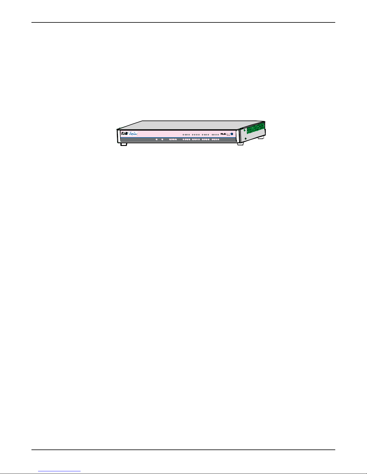
Voice/Fax 5Voice/Fax 6Voice/Fax 7Voice/Fax 8
XMT RCVXSG RSG XMTRCV XSG RSGXMT RCV XSGRSG
Voice/Fax 1Voice/Fax 2Voice/Fax 3 Voice/Fax 4EthernetBootPower
RCV XMT COLLNK XMTRCV XSG RSG
XMT RCVXSG RSG
Figure 1-1: TA-410/810 Chassis
Capacity. TalkAnytime model TA810 is an eight-channel unit that can carry 8 simultaneous audio
conversations. The model TA410 is a four-channel unit that can carry 4 simultaneous audio conversations..
Both of these units have a 10/100Mbps Ethernet interface and a command port for configurat ion.
XMTR CV XSGRSG
XMTRCV XSG RSG
XMTRCV XSG RSG
Mounting. Mechanically, the TA410 and TA810 units are designed for a one-high industry-standard EIA
19-inch rack enclosure. The product must be installed by qualified service personnel in a restricted- acces s
area, in accordance with Articles 110-16, 10-17, and 110-18 of the National Electrical Code, ANSI/NFPA 70.
Phone System Transparency. These TalkAnytime units inter-operate with a telephone switch or PBX,
acting as a switching device that directs voice calls originating on an IP network into a PBX or key
telephone system. The TalkAnytime units have “phonebooks,” directories that determine from whom calls
may be received. The TalkAnytime can be set to give the caller a dial tone that allows them to dial
extensions within a PBX or key telephone system.
Management. Configuration and system management can be done locally with the TalkAnytime
configuration software. After an IP address has been assigned locally, other configuration can be done
remotely using the TalkAnytime web browser GUI. Remote system management can be done with the
TalkAnytime web browser GUI. All of these control software packages are included on the Product CD.
Multi-Tech Systems, Inc. TalkAnyTime User Guide 8
Page 9

Chapter 1: Overview
While the web GUI’s appearance differs slightly, its content and organization are essentially the same as
that of the Windows GUI (except for logging).
The primary advantage of the web GUI is remote access for control and configuration. The controller PC
and the TalkAnytime unit itself must both be connected to the same IP network and their IP addresses must
be known.
Multi-Tech Systems, Inc. TalkAnyTime User Guide 9
Page 10
Chapter 1: Overview
Once you’ve begun using the web browser GUI, you can go back to the TalkAnytime Windows GUI at any
time. However, you must log out of the web browser GUI before using the TalkAnytime Windows GUI.
Logging of System Events. MultiTech has built SysLog Server functionality into the software of the
TalkAnytime units. SysLog is a de facto standard for logging events in network communication systems.
The SysLog Server resides in the TalkAnytime unit itself. To implement this functionality, you will need a
SysLog client program (sometimes referred to as a “daemon”). SysLog client programs, both paid and
freeware, can be obtained from Kiwi Enterprises, among other firms. See www.kiwisyslog.com
client programs essentially give you a means of structuring console messages for convenience and ease of
use.
MultiTech Systems does not endorse any particular SysLog client program. SysLog client programs by any
qualified provider should suffice for use with TalkAnytime units. Kiwi’s brief description of their SysLog
program indicates the typical scope of such programs. “Kiwi Syslog Daemon is a freeware Syslog Daemon
for the Windows platform. It receives, logs, displays and forwards Syslog messages from hosts such as
routers, switches, Unix hosts and any other syslog enabled device. There are many customizable options
available.”
TalkAnytime Front Panel LEDs
LED Types. The TalkAnytime units have two types of LEDs on their front panels:
(1) general operation LED indicators (for power, booting, and
ethernet functions), and
(2) channel operation LED indicators that describe the data traffic and performance in each data
channel.
Active LEDs. On both the TA410 and TA810, there are eight sets of channel-operation LEDs. However, on
the TA410, only the lower four sets of channel-operation LEDs are functional. On the TA810, all eight sets
are functional.
. SysLog
Multi-Tech Systems, Inc. TalkAnyTime User Guide 10
Figure 1-3. TA-410/810 LEDs
Page 11

Analog TalkAnytime LED Descriptions
TA-410/810 Front Panel LED Definitions
LED NAME DESCRIPTION
General Operation LEDs (one set on each TalkAnytime model)
Power Indicates presence of power.
Chapter 1: Overview
Boot
Ethernet
After power up, the Boot LED will be on briefly while the TalkAnytime is booting. It lights
whenever the TalkAnytime is booting or downloading a setup configuration data set.
FDX. LED indicates whether Ethernet connection is half-duplex or full-duplex
(FDX) and, in half-duplex mode, indicates occurrence of data collisions. LED is on
constantly for full-duplex mode; LED is off constantly for half-duplex mode. When
operating in half-duplex mode, the LED will flash during data collisions.
LNK. Link/Activity LED. This LED is lit if Ethernet connection has been made. It
is off when the link is down (i.e., when no Ethernet connection exists). While link is
up, this LED will flash off to indicate data activity.
Channel-Operation LEDs (one set for each channel)
XMT
RCV
XSG
RSG
Transmit. This indicator blinks when voice packets are being transmitted to the
local area network.
Receive. This indicator blinks when voice packets are being received from the
local area network.
Transmit Signal. This indicator lights when the FXS-configured channel is off-
hook, the FXO-configured channel is receiving a ring from the Telco, or the M lead
is active on the E&M configured channel. That is, it lights when the TalkAnytime is
receiving a ring from the PBX.
Receive Signal. This indicator lights when the FXS-configured channel is ringing,
the FXO-configured channel has taken the line off-hook, or the E lead is active on
the E&M-configured channel.
Command Computer Requirements
The computer on which the TalkAnytime unit’s configuration program is installed must meet these
requirements:
• must be IBM-compatible PC with MS Windows operating system;
• must have an available COM port for connection to the TalkAnytime.
However, this PC does not need to be connected to the TalkAnytime permanently. It only needs to be
connected when local configuration and monitoring are done. Nearly all configuration and monitoring
functions can be done remotely via the IP network.
Multi-Tech Systems, Inc. TalkAnyTime User Guide 11
Page 12

Chapter 1: Overview
Client Computer Requirements
To make an incoming call using TalkAnytime, the computer must meet the requirements described in the
table below.
Category Requirement
Operating System Windows 98 or Windows XP
Browser Internet Explorer 5.0 or higher
Audio Hardware Microphone & Speaker (in any form)
O.S. Settings Headset or microphone/speaker combo
must be activated and not pre-empted by
any other audio hardware or software.
Browser Settings Popup Blocking must be disabled at least
for the IP address at which the
TalkAnytime unit is operating..
Activex controls must be enabled.
In terms of audio hardware, many combinations are possi ble. In any event, the computer must have both a
microphone and an audio output device and they must be activated. A headset that includes both a
microphone and a speaker (connected to the appropriate jacks on the computer’s sound card) would meet
this requirement. The computer might have a built-in microphone and built-in or extension speakers and
such a combination would also meet this requirement.
Multi-Tech Systems, Inc. TalkAnyTime User Guide 12
Page 13

Specifications
Chapter 1: Overview
Parameter
/Model
Operating
Voltage/
Current
Mains
Frequencies
Power
Consumption
Mechanical
Dimensions
Weight
100-240 VAC
1.2 - 0.6 A
50/60 Hz 50/60 Hz
29 watts 46 watts
1.75” H x
17.4” W x
8.5” D
4.5cm H x
44.2 cm W x
21.6 cm D
7.1 lbs.
(3.2 kg)
TA410
Installation at a Glance
The basic steps of installing your TalkAnytime unit involve
TA810
100-240 VAC
1.2 - 0.6 A
1.75” H x
17.4” W x
8.5” D
4.5cm H x
44.2 cm W x
21.6 cm D
7.7 lbs.
(3.5 kg)
• unpacking the unit,
• connecting the cables,
• configuring it using management software (TalkAnytime Configuration software),
• making phonebook entries to determine routing of incoming calls,
• establishing a TalkAnytime URL that includes certain operating parameters
and placing a link to that URL on a website, and
• confirming connectivity on an incoming call.
This process results in a fully functional click-to-talk system.
Multi-Tech Systems, Inc. TalkAnyTime User Guide 13
Page 14

Chapter 1: Overview
Related Documentation
The TalkAnytime User Guide (the document you are now reading) comes in electronic form and is
included on your system CD. It presents in-depth information on the f eatures and functionali ty of MultiTech’s TalkAnytime Product Family.
TM
The CD media is produced using Adobe Acrobat
print your copy of a user guide, load Acrobat Reader
the TalkAnytime CD and is also a free download from Adobe’s Web Site:
for viewing and printing the user guide. To view or
TM
on your system. The Acrobat Reader is included on
www.adobe.com/prodindex/acrobat/readstep.html
This TalkAnytime User Guide is also available on Multi-Tech’s Web site at:
http://www.multitech.com
Viewing and printing a user guide from the Web also requires that you have the Acrobat Reader loaded on
your system. To select the TalkAnytime User Guide from the Multi-Tech Systems home page, click Documents and then click
TalkAnytime in the product list drop-down window. All TalkAnytime documents will be displayed. You can then choose
User Guide to view or download the .pdf file.
The TalkAnytim e CD also includes , as PDF files, sing le-page descript ions for end-users about how to use Talk Anytime. One
document pertains to calls directed to a phone pool. A second document pert ains to incoming calling where the caller can, after
connection, dial specific ext ensions within the organization’s PBX. A third document pertains to use of the TalkAnytime by
trusted parties who are allowed full access to the PBX including PSTN access.
Entries (organized by model number) in the “knowledge base” and ‘troubleshooting resolutions’ sections of
the MultiTech web site (found under “Support”) constitute another source of help for problems
encountered in the field.
Multi-Tech Systems, Inc. TalkAnyTime User Guide 14
Page 15

Chapter 2: Quick Start Instructions
Multi-Tech Systems, Inc. TalkAnyTime User Guide 15
Page 16
TalkAnytime Quick Start Instructions Startup Tasks
Introduction
The Quick Start Instructions are streamlined instructions intended to get the TalkAnytime unit up and
running quickly. These start-up instructions include assistance on setting up the TalkAnytime unit’s
Inbound Phonebook and defining the URL expression, which includes some parameter settings.
A printed Cabling Guide is shipped with the TalkAnytime unit and an electronic copy is included on the
Product CD.
TalkAnytime Startup Tasks
Task Summary
z Collecting Phone/IP
Details ( vital! )
z Placement
z Command/Control
Computer Setup:
Specs & Settings
The TalkAnytime must be configured to
interface with your particular phone
system and IP network. To do so,
certain details must be known about
those phone and IP systems.
Decide where you’ll mount the unit.
Some modest minimum specifications
must be met. A COM port must be set
up.
z Hookup Connect power, phone, and data cables
per diagram.
z Software Installation This is the configuration program.
It’s a standard Windows software
installation.
z Phone/IP Starter
Configuration
z Phonebook/URL Starter
Configuration
You will enter phone numbers and IP
addresses. You’ll use default parameter
values where possible to get the system
running quickly.
Use “Config Info CheckList” (page 18).
The phonebook is where you specify
how calls will be routed. A special URL
determines how the TalkAnytime will
interact with your web server.
z Connectivity Test You’ll find out if your TalkAnytime
system can receive phone calls from
visitors to your web site. That means
you’re up and running!
z Troubleshooting Detect and remedy any problems that
might have prevented connectivity.
Multi-Tech Systems, Inc. TalkAnyTime User Guide 16
Page 17
TalkAnytime Quick Start Instructions Gathering Phone/IP Details
Phone/IP Details *Absolutely Needed*
Before Starting the Installation
The TalkAnytime will interface with both the IP network and the phone system. You must gather
information about the IP network and about the phone system so that the TalkAnytime can be configured
to operate with them properly. A summary of this configuration information appears on page 18 (“Config
Info CheckList”).
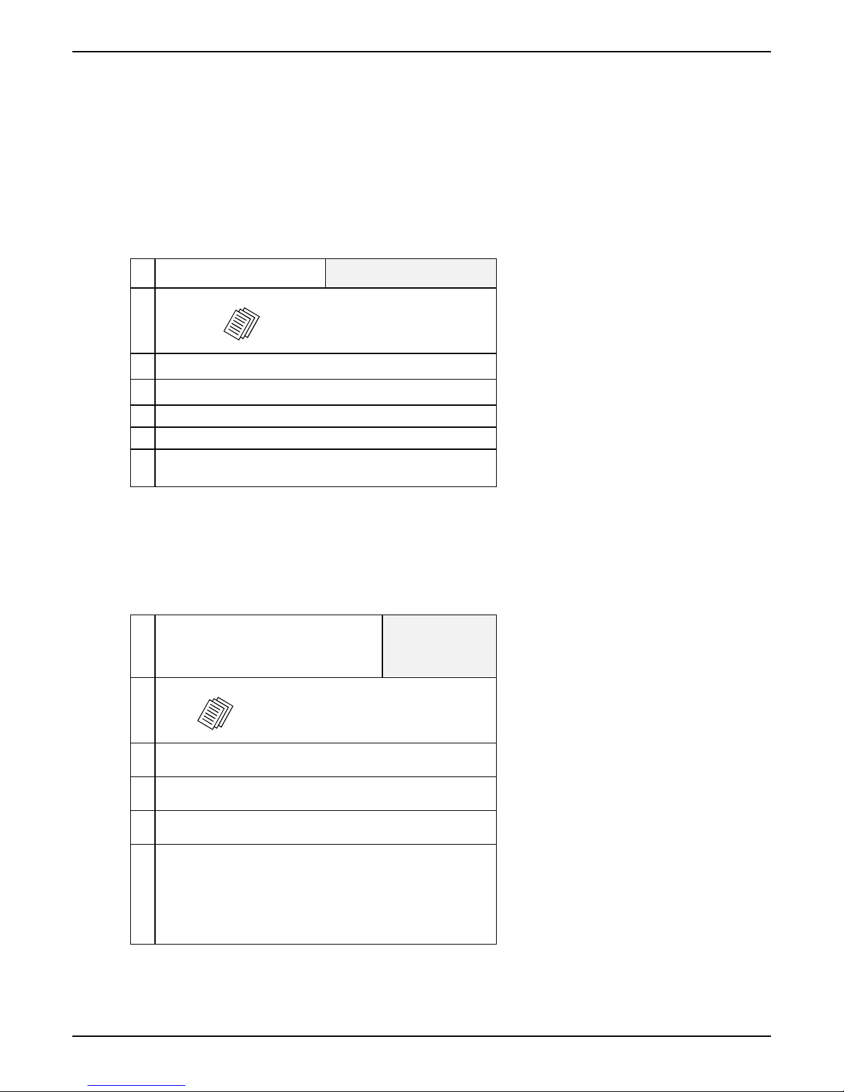
Gather IP Information
Ask your computer network
9
administrator.
#
• IP Address
• IP Mask
• Gateway
• Domain Name Server (DNS) Info (optional)
• Determine whether or not 802.1p Packet Prioritization
will be used.
IP Network Parameters:
Record for this
TalkAnytime unit.
Phone/IP Details *Absolutely Needed*
Gather T elephone Information
Analog Phone Parameters
9
Ask phone company or
telecom manager.
#
• Which interface type is used?
E&M_____ FXS/FXO_____
• If FXS, determine whether the line will be used for a
phone, fax, or KTS (key telephone system)
• If FXO, determine if line will be an analog PBX
extension or an analog line from a telco central office
• If E&M, determine these aspects of the E&M trunk
line from the PBX:
• What is its Type (1, 2, 3, 4, or 5)?
• Is it 2-wire or 4-wire?
• Is it Dial-Tone or Wink?
Multi-Tech Systems, Inc. TalkAnyTime User Guide 17
Analog Telephony Interface Parameters:
Record for this VOIP Site
Page 18
TalkAnytime Quick Start Instructions Gathering Phone/IP Details
Phone/IP Details Often Needed/Wanted
Obtain Email Address for TalkAnytime (for email call log reporting)
required if log reports of
TalkAnytime call traffic
are to be sent by email
Optional
SMTP Parameters
Preparation Task:
Ask Mail Server
administrator to set up
email account (with
password) for the
TalkAnytime unit itself.
Be sure to give a unique
identifier to each
individual TalkAnytime
unit.
Get the IP address of the
mail server computer, as
well.
To: I .T. De par t men t
re: email accoun t for VOIP
voip-unit2@biggytech.com
Config Info CheckList
Type of Config Info Gathered TalkAnytime
Configuration screen
on which to enter
Config Info
IP info for TalkAnytime unit
● IP address
● Gateway
● DNS IP (if used)
● 802.1p Prioritization (if used)
Interface Type
(Choices: E&M, FXS/FXO*)
E&M info (only if E&M is used)
● Type (1-5) ● 2 or 4 wires?
● Dial Tone or Wink?
Country Code Regional Parameters
Email address for TalkAnytime unit
(optional)
Reminder: Be sure to Save Setup after entering configuration values.
Multi-Tech Systems, Inc. TalkAnyTime User Guide 18
√
Ethernet/IP Parameters
Interface Parameters
*In FXO/FXS systems,
channels used for phone, fax,
or key system are FXS;
channels used for analog PBX
extensions or analog telco
lines are FXO.
Interface Parameters
SMTP Parameters
Page 19

TalkAnytime Quick Start Instructions Placement
Placement
Mount your TalkAnytime unit in a safe and convenient location where cables for your network and phone
system are accessible. Rack-mounting instructions are in Chapter 3: Mechanical Installation & Cabling of the
User Guide.
Command/Control Computer Setup (Specs & Settings)
The computer used for command and control of the TalkAnytime
(a) must be an IBM-compatible PC,
(b) must use a Microsoft operating system,
(c) must be connected to your local network (Ethernet) system, and
(d) must have an available serial COM port.
The configuration tasks and control tasks the PC will have to do with the TalkAnytime are not especially
demanding. Still, we recommend using a reasonably new computer. The computer that you use to
configure your TalkAnytime need not be dedicated to the TalkAnytime after installation is complete.
COM port on controller PC. You’ll need an available COM port on the controller PC. You’ll need to know
which COM port is available for use with the TalkAnytime (COM1, COM2, etc.).
Multi-Tech Systems, Inc. TalkAnyTime User Guide 19
Page 20

TalkAnytime Quick Start Instructions Client Computer Requirements
Client Computer Requirements
To make an incoming call using TalkAnytime, the computer must meet the requirements described in the
table below.
Category Requirement
Operating System Windows 98 or Windows XP
Browser Internet Explorer 5.0 or higher
Audio Hardware Microphone & Speaker (in any form)
O.S. Settings Headset or microphone/speaker combo
must be activated and not pre-empted by
any other audio hardware or software.
Browser Settings Popup Blocking must be disabled for the
IP address of the TalkAnytime unit.
(Popup Blocking need not be disabled
globally.)
Activex controls must be enabled.
In terms of audio hardware, many combinations are possi ble. In any event, the computer must have both a
microphone and an audio output device and they must be activated. A headset that includes both a
microphone and a speaker (connected to the appropriate jacks on the computer’s sound card) would meet
this requirement. The computer might have a built-in microphone and built-in or extension speakers and
such a combination would also meet this requirement.
Multi-Tech Systems, Inc. TalkAnyTime User Guide 20
Page 21
TalkAnytime Quick Start Instructions Quick Hookup
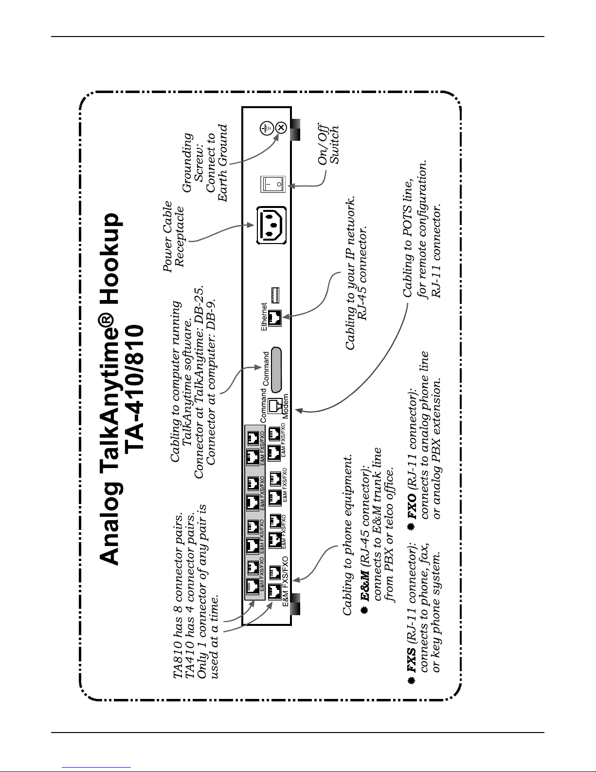
Quick Hookup for TA410 & TA810
Multi-Tech Systems, Inc. TalkAnyTime User Guide 21
Page 22

TalkAnytime Quick Start Instructions Configuration Software Installation
Install TalkAnytime Configuration Software onto Command PC
For more details, see Chapter 4: Software Installation in User Guide.
1. TalkAnytime unit must be properly cabled. Power must be turned on.
2. Insert TalkAnytime CD into drive. Allow 10-20 seconds for Autorun to start. If Autorun fails, go to
My Computer | CD ROM drive | Open. Click Autorun icon.
3. At first dialog box, click Install Software.
4. At ‘welcome’ screen, click Next.
5. Follow on-screen instructions. Accept default program folder location and click Next.
6. Accept default icon folder location. Click Next. Files will be copied.
7. Select available COM port on command/control computer.
8. At completion screen, click Finish.
9. At the prompt “Do you want to run TalkAnytime Configuration?,” click No. Software installation is
complete.
Phone/IP Starter Configuration
Full details here: Technical Configuration chapter in User Guide
1. Open the TalkAnytime program:
Start | TalkAnytime xxx | Configuration.
2. Go to Configuration | Ethernet/IP. Enter the IP parameters for your TalkAnytime unit. Activate Packet
Prioritization (802.1p) if desired. For details, see the “Technical Configuration” chapter of the User Guide.
3. Do you want to configure and operate the TalkAnytime unit using the web browser GUI? (It has the
same functionality as the local Windows GUI, but offers remote access.)
If NO, skip to step 5. If YES, continue with step 4.
4. Web Browser GUI Setup (Optional). To do configuration and operation procedures using the web
browser GUI, you must first set it up. To do so, follow these steps. (The browser used must be Internet
Explorer 6.0 or above; or Netscape 6.0 or above; or FireFox 1.0 or above.)
A. Be sure an IP address has been
assigned to the TalkAnytime unit
(this must be done in the
TalkAnytime Windows GUI).
B. Save Setup in Windows GUI.
C. Close the TalkAnytime Windows
GUI.
D. Install Java program from
TalkAnytime product CD.
(Must be Java Runtime
Environment 1.4.2_01 or above.)
NOTE: Required on first use of
Web Browser GUI only.
Need more
info?
See “Web Browser Interface” in Operation &
Maintenance chapter of User Guide (on CD).
E. Open web browser.
(Note: The PC being used must
be connected to and have an IP
address on the same IP network
that the TalkAnytime is on.)
F. Browse to IP address of
TalkAnytime unit.
G. If username and password have
been established, enter them
when prompted by the
TalkAnytime.
H. Use web browser GUI to
configure or operate the
TalkAnytime unit.
Multi-Tech Systems, Inc. TalkAnyTime User Guide 22
Page 23

TalkAnytime Quick Start Instructions Phone/IP Starter Configuration
Once you’ve begun using the web browser GUI, you can go back to the TalkAnytime Windows GUI
at any time. However, you must log out of the web browser GUI before using the TalkAnytime
Windows GUI.
5. Go to Configuration | Voice/Fax. Select Coder | “Automatic.” At the right-hand side of the dialog box,
click OK. If you know any specific parameter values that will apply to your system, enter them. Click
Copy Channel. Select Copy to All. Click Copy. At main Voice/Fax Parameters screen, click OK to exit
from the dialog box.
6. Enter telephone system information.
Go to Configuration | Interface. Enter parameters obtained from phone company or PBX administrator.
7. Go to Configuration | Regional Parameters. Select the Country/Region that fits your situation. Click
OK and confirm. Click OK to exit from the dialog box.
8. Go to Configuration | Regional Pa rameters. In the Country Selection for Built-In Modem field (drop-
down list), select the country that best fits your situation. (This may not be the same as your selection for
the Country/Region field. The selections in the Country Selection for Built-In Modem field entail more
detailed groupings of telephony parameters than do the Country/Region values.)
9. Do you want the phone-call logs produced by the TalkAnytime to be sent out by email (to your
Administrator or someone else)?
If NO, skip to step 11.
If YES, continue with step 10.
10. Go to Configuration | SMTP.
SMTP lets you send phone-call log records to the TalkAnytime Administrator by email. Select Enable
SMTP.
You should have already obtained an email address for the TalkAnytime itself (this serves as the
origination email account for email logs that the TalkAnytime can email out automatically).
Enter this email address in the “Login Name” field.
Type the password for this email account.
Multi-Tech Systems, Inc. TalkAnyTime User Guide 23
Page 24

TalkAnytime Quick Start Instructions Phone/IP Starter Configuration
Phone/IP Starter Configuration (continued)
Enter the IP address of the email server where the TalkAnytime’s email account is located in the “Mail
Server IP Address” field.
Typically the email log reports are sent to the TalkAnytime Administrator but they ca n be sent to any
email address. Decide where you want the email logs sent and enter that email address in the “Recipient
Address” field.
Whenever email log messages are sent out, they must have a standard Subject line. Something like
“Phone Logs for TalkAnytime N” is useful. If you have more than one TalkAnytime unit in the building,
you’ll need a unique identifier for each one (select a useful name or number for “N”). In this “Subject”
field, enter a useful subject title for the log messages.
In the “Reply-To Address” field, enter the email address of your Administrator.
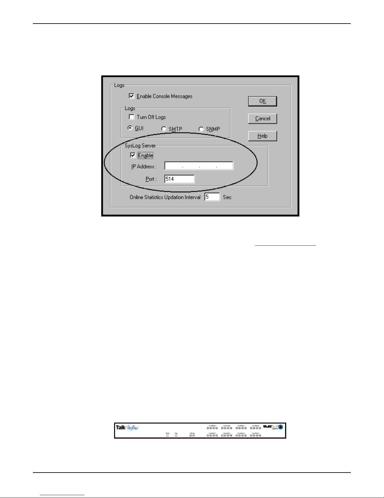
11. Go to Configuration | Logs.
Select “Enable Console Messages.”
To allow log reports by email (if desired), click SMTP. Click OK.
To do logging with a SysLog client program, click on “SysLog Server – Enable” in the Logs screen. To
implement this function, you must install a SysLog client program. For more info, see the “SysLog Server
Functions” section of the Operation & Maintenance chapter of the
User Guide.
12. Go to Save Setup | Save and Reboot. Click OK. This will save the para meter values that you have just
entered.
The TalkAnytime unit’s “BOOT” LED will light up while the configuration file is being saved and loaded
into the TalkAnytime. Don’t do anything to the TalkAnytime until the “BOOT “LED is off (a loss of
power at this point could cause the TalkAnytime unit to lose the configuration settings you have made).
END OF PROCEDURE.
Multi-Tech Systems, Inc. TalkAnyTime User Guide 24
Page 25

TalkAnytime Quick Start Instructions Phonebook Configuration
Inbound Phonebook
1. Open the TalkAnytime program.
( Start | TalkAnytime xxx | Configuration )
2. Go to Phone Book | Inbound Phonebook | Add Entry.
3. In the “Remove Prefix” field, enter the PBX extension to which you want to direct the incoming
TalkAnytime calls.
4. In the “Add Prefix” field, enter the same digits as were entered in the “Remove Prefix” field.
5. In the “Channel Number” field, enter “Hunting.” A “hunting” value means the TalkAnytime unit will
assign the call to the first available channel.
If desired, specific channels can be assigned to specific incoming calls (i.e., to any set of calls received
with a particular incoming dialing pattern).
6. In the “Description” field, enter an identifier (letters and/or digits) that describes the destination of the
incoming TalkAnytime calls. The identifier entered in this field must match the identifier used in the
Service field of the TalkAnytime URL. The description should make the routing of calls easy to
understand. (40 characters max.)
7. Repeat steps 2-6 for each inbound phonebook entry. As noted above, each channel of the TalkAnytime
unit can be configured separately, have its own values in the “Remove Prefix” and “Add Prefix” fields
and its own “Description” value. Or all channels can be configured alike. When all entries are complete,
go to step 8.
8. Click OK to exit the inbound phonebook screen.
9. Click on Save Setup. Highlight Save and Reboot. Click OK.
Your starter inbound phonebook configuration is complete.
Multi-Tech Systems, Inc. TalkAnyTime User Guide 25
Page 26

TalkAnytime Quick Start Instructions URL Configuration
TalkAnytime URL Configuration
End users will access the TalkAnytime by clicking on an icon on a web site. The web server must include a
URL link expression that not only directs the caller to the TalkAnytime unit but also specifies values for
several other parameters (four parameters are required; two are optional).
The general form of the URL expression is as follows:
TalkAnytime URL Command Line
http://a.b.c.d/tat.cgi?Service=string1&Protocol=n&Codec=q&SC=w
&Packetization=y&Digits=z
Configuration
Parameter
Involved
TalkAnytime
IP Address
Portion of URL in
question
where a, b, c, and d are
variables;
Values: 0 to 255
Service where string1 is a variable;
Values: any
letters/numbers;
no spaces, periods,
commas, or symbols;
40 characters max.
Protocol where n is a variable;
This value must match the value of the
Description field in the Inbound Phonebook.
Values: TCP or UDP
Codec where q is a variable;
Values: G711A, G711U,
G723
Silence
Compression
where w is a variable;
Values: ON, OFF
Packetization where y is a variable;
Values: 30, 60, 90, 120
Digits where z is a variable;
Values: Yes, No
allowed variant
tatfrm.cgi? Eliminates black background behind TalkAnytime
of tat.cgi?
Optional parameter. If omitted, remove the
entire expression “SC=w” from URL.
Optional parameter. If omitted, remove the entire
expression “Packetization=y” from URL.
When Digits=No, the end user can use the
TalkAnytime keypad to dial only after connection
has been made. When Digits=Yes, TalkAnytime
keypad is available immediately.
user screen.
Note: All non-italicized characters in the URL expression are fixed literal characters that
must be included verbatim. As noted above, the tat.cgi? expression has an
allowed variant.
Use of phonebook entries and URL command lines is illustrated in the
that follows.
Comment
TalkAnytime System Examples section
Multi-Tech Systems, Inc. TalkAnyTime User Guide 26
Page 27
TalkAnytime Quick Start Instructions System Examples
TalkAnytime System Examples
Introduction
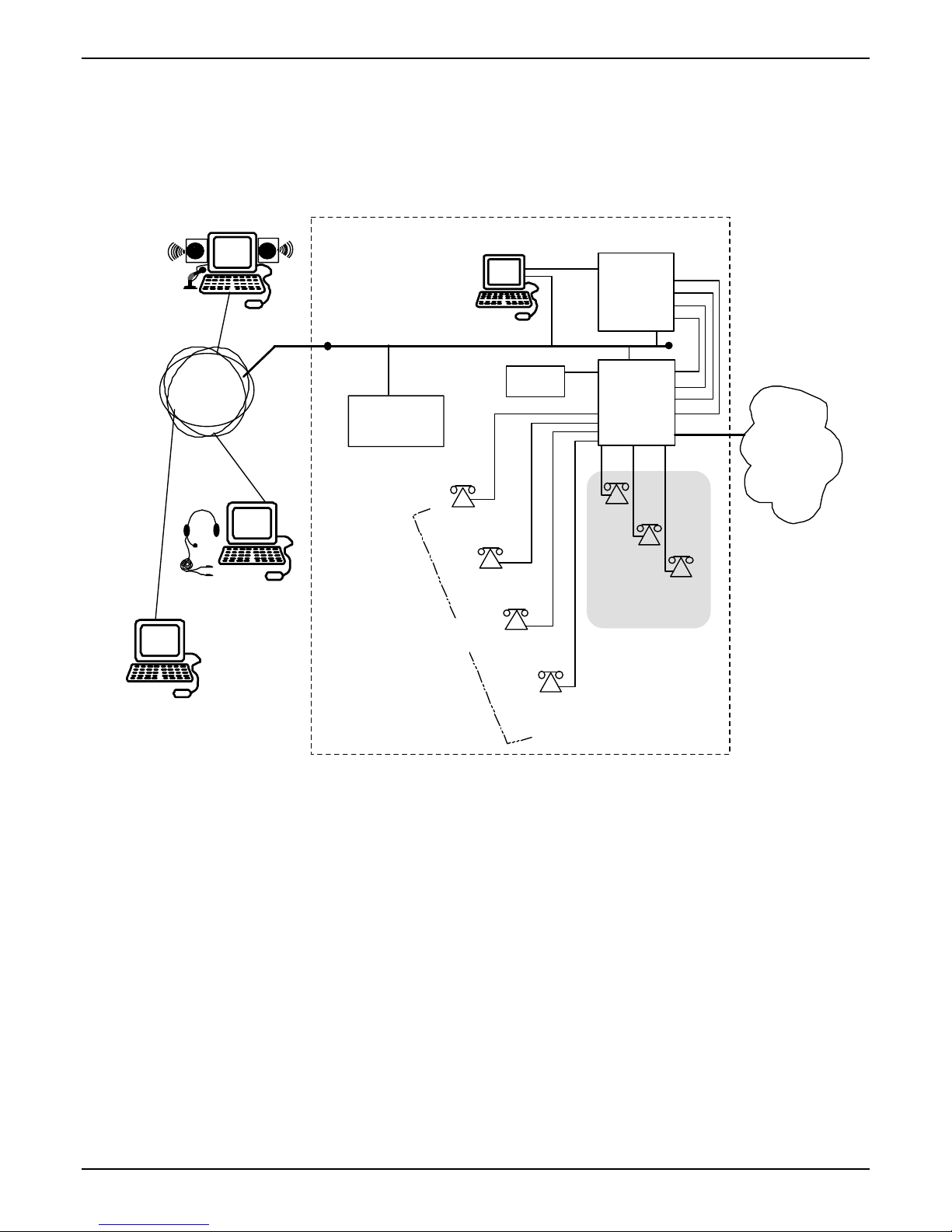
The following example shows how the TalkAnytime unit operates in a specific telecommunications system.
Home PC User A
Command PC
Whir lygi g Gad get
Company Office s
Ethernet LAN
Talk
Anytime
TA410
FXO
FXO
FXO
FXO
Internet
PBX
Web Server
PSTN
IVR
x8651
Comblasticator
Specialist
MI C
SPKR
Home PC User B
Customer
Service
Dept.
Traveling
Whirlygi g
Manager
x8652
Zanfraditron
Spec ialist
x8653
Fridnorpulizer
Spec ialist
x86 54
Gronplostramax
Spe cialist
In this system, the TalkAnytime unit is connected to a PBX system. Incoming calls are directed to two
different departments, the Sales Department (where all call recipients are peers and it is satisfa c tory for the
incoming caller to reach any one of them) and the Customer Service Department (where each call recipient
is a specialist). We show 3 callers. Two are customers; the computer of one is equipped with a
microphone/speaker headset; the computer of the other has external speakers and an external microphone.
The third caller is an employee of the Whirlygig Gadget Company, a trusted party who has instructions on
how to use the TalkAnytime unit to reach the public phone system (PSTN) as well as other Whirlygig
employees through the PBX.
x7301
Sales
Dept.
x73 02
x73 03
Multi-Tech Systems, Inc. TalkAnyTime User Guide 27
Page 28
TalkAnytime Quick Start Instructions System Examples
Example Types. We will show a configuration of TalkAnytime settings that allows 3 different types of calls:
(a) calls into a phone pool,
(b) calls directed to specific individual phones through an IVR (a voice recording device connected
to a PBX and that plays a recorded message and allows callers to dial different extensions with
DTMF signals from phone or keypad), and
(c) calls by a trusted party into an institutional PBX and out into the local public phone system
(PSTN).
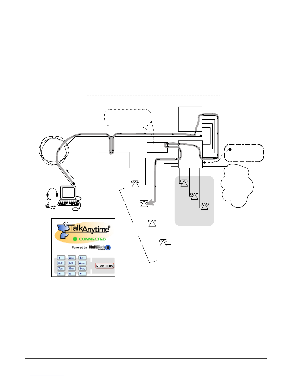
Calls into a Phone Pool
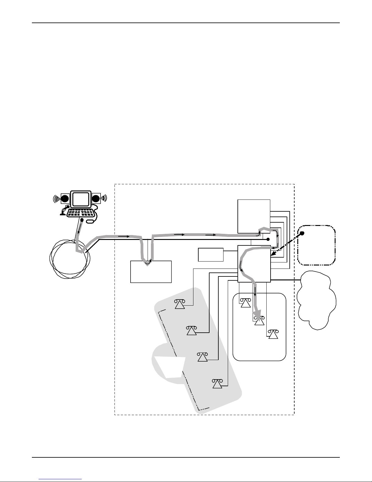
User-A Calls Sales Department. The drawing below shows a call coming into the Whirlygig Sales
Department from a prospective customer. The PBX is set up to ‘hunt’ among a group of extensions allotted
to the Sales Department. The TalkAnytime unit directs calls originating through the Whirlygig web server
to the PBX and into the phone pool of sales representatives.
The main settings of the TalkAnytime Configuration Program, Phonebook, and web server URL that are
required to implement this capacity are shown in the second drawing below.
Home PC User A
65.129.90.200
Call
starts
here.
Internet
Whi r lygi g Gadget
Com pany Off ices
Path of Ca ll
Web Server
Ethernet LAN
x8651
Comblasticator
Specialist
Zanfraditron
Specialist
Customer
Service
Dept.
IVR
x8652
x8653
Fridnorpul izer
Specialist
Talk
Anytime
TA 41 0
466-0000
x7301
x7302
Sales
Dept.
PBX
717-
FXO
FXO
FXO
FXO
PBX is
set to ‘hun t’
among
extensions
7300-7399.
PSTN
x73 03
Multi-Tech Systems, Inc. TalkAnyTime User Guide 28
x8654
Gronplostramax
Spec ia list
Page 29
TalkAnytime Quick Start Instructions System Examples
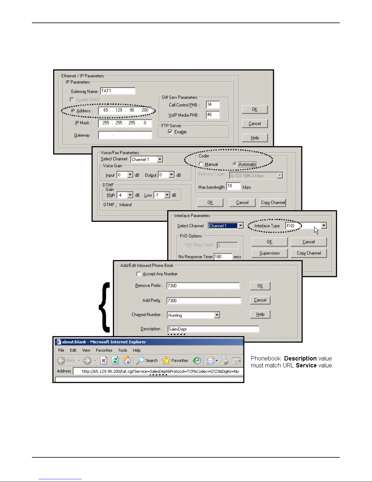
Technical Configuration for Phone Pool Call
Multi-Tech Systems, Inc. TalkAnyTime User Guide 29
Page 30
TalkAnytime Quick Start Instructions System Examples
Calls to Specific Extensions Through an IVR
User-B Calls Customer Service Speciali st . The drawing below shows a call coming into a particular
product specialist in the Whirlygig Customer Service Department from customer concerned about a
“Zanfraditron” device (a fictional product contrived for this example). The PBX is equipped with an IVR
(which produces outgoing messages and allows DTMF in return from the caller) at extension 8600. In
response to the outgoing message, the caller dials the desired extension for the Zanfraditron specialist on
the TalkAnytime keypad and the connection is made.
The main settings of the TalkAnytime Configuration Program, Phonebook, and web server URL that are
required to allow this kind of incoming call are shown in the second drawing below.
Whirlygig Gadget
Company Offices
65.129.90.200
Ta lk
Anytime
TA410
FXO
FXO
FXO
FXO
PBX
717-
466-0000
PBX is set
to route calls
to 8600 to IVR.
Internet
Path of Ca ll
IVR’s Outgoing Message
“Welcome to Whirlygig.....
To speak to a Zanfraditron
specialist, dial 8652.”
Ethernet LAN
Web Server
IVR
ext 8600
MIC
SPKR
Home PC User B
Call
starts
here.
After hearing IVR’s outgoing message,
ca ller uses Tal kAnytime keyp ad to dial
the desired extension.
x8651
Comblas tic ator
Specialist
Zanfraditron
Spec ialis t
Customer
Service
Dept.
x8652
x8653
Fridnorpul izer
Specialist
Gronplostramax
Spec ialis t
x865 4
x7301
Sales
Dept.
PSTN
x730 2
x73 03
Multi-Tech Systems, Inc. TalkAnyTime User Guide 30
Page 31

TalkAnytime Quick Start Instructions System Examples
Technical Configuration for Specific Extension Calls via IVR
Alternative Method to Access Multiple Extensions.
extensions of the PBX. Specifically, the end-user used the TalkAnytime keypad to dial digits in response to instructions
given in the IVR’s outgoing message.
Be aware that external extensions could have been reached in another way without an IVR: the end-user could be
allowed to dial any extension on the PBX from the TalkAnytime keypad (determined by the setting Digits=Yes in the
URL). In that case, the PBX would have to be configured in a way that blocks PSTN calling by the PBX extensions to
which the TalkAnytime channels are connected. In either method, it is important to prevent unwanted access to the
PSTN and especially toll calling through the PBX.
Multi-Tech Systems, Inc. TalkAnyTime User Guide 31
In this example, we used an IVR to allow access to various
Page 32

TalkAnytime Quick Start Instructions System Examples
Inbound Phonebook List for Entire Example System
The three uses of the TalkAnytime described here can be implemented simultaneously in a single system.
Each type of use entails its own entry in the Phonebook. The resulting phonebook list is shown below.
Multi-Tech Systems, Inc. TalkAnyTime User Guide 32
Page 33

TalkAnytime Quick Start Instructions System Examples
Calls by Trusted Party into PBX and Beyond
Employee Accesses PSTN of Home City Thru PBX. The drawing below shows a trusted party using
TalkAnytime to access the PSTN of the company’s home office and, from there, to make a call to his home
residence. In this case, the caller does not need to surf to the company’s home page to begin. Once an
Internet connection is established, the user can simply type the private (and secret) URL that he has been
given into the browser, press ENTER, and be connected to the TalkAnytime unit. When the TalkAnytime
dialing pad appears, the user can dial just as if he/she were at his desk at the company’s home office.
NOTE: Since this arrangement gives access to the company’s PBX and consequent
financial liability for toll charges incurred, such authorization should only be
given to trusted parties.
The main settings of the TalkAnytime Configuration Program, Phonebook, and web server URL that are
required to allow this kind of incoming call are shown in the second drawing below.
Trusted Party Calling Through PBX
Joe connects to Internet and
1
enters his own private URL
provided for convenience of
trusted traveling employees.
(It's not necessary to surf to
Whirlygig site. URL contains
all needed information.)
Whirlygig Gadget
Company Offices
Path of Call
Talk
Anytime
TA410
FXO
FXO
FXO
FXO
Ethernet LAN
IVR
Internet
Web Server
PBX
717-
466-0000
PSTN
x73 01
Sales
Dept.
x7302
x7303
NOTE
This type of use of
TalkAnytime entails
risk of misuse of
access to PBX and
resulting toll charges.
It is to be used only
with trusted personnel.
Joe’s
Hou se
Call
starts
here.
SPKR
Traveling
Whirlygig
Manager
“Joe”
MIC
When the TalkAnytime
2
dial pad appears, Joe
can dial into the PSTN
of the Whirlygig office site
(for example, to call home)
just as he would from his
own office in the
Whirlygig building.
x8651
Comblas ticator
Sp e ci a li st
Zanfraditron
Customer
Service
Dept.
x8 652
Specialist
x8653
Fridnorp ulizer
Special is t
x8654
Gronplostr amax
Spec ialis t
Multi-Tech Systems, Inc. TalkAnyTime User Guide 33
Page 34

TalkAnytime Quick Start Instructions System Examples
Technical Configuration for Trusted-Party Calling Through PBX
Multi-Tech Systems, Inc. TalkAnyTime User Guide 34
Page 35

TalkAnytime Quick Start Instructions End-User’s Perspective
User’s Perspective of TalkAnytime
For end-users TalkAnytime is an opportunity to conduct a toll-free voice call directly from their computers.
The process begins when a user responds to a “click-to-talk” opportunity on a web site.
In the example shown here, the user can click on a rectangular icon to speak to a sales agent or on a
diamond-shaped icon to speak to a customer service representative.
When the user clicks on either of these icons, the website will respond first by checking that the user’s PC
meets the basic requirements to use TalkAnytime.
These are the requirements:
User PC Requirements for TalkAnytime
Category Requirement
Operating System Windows 98 or Windows XP
Browser Internet Explorer 5.0 or higher
Audio Hardware Microphone & Speaker (in any form)
O.S. Settings Headset or microphone/speaker combo
Browser Settings Popup Blocking must be disabled, at
Multi-Tech Systems, Inc. TalkAnyTime User Guide 35
must be activated and not pre-empted by
any other audio hardware or software.
least for the IP address at which the
TalkAnytime unit is operating.
Page 36

TalkAnytime Quick Start Instructions End-User’s Perspective
ActiveX controls must be enabled.
Qualifications Query Window. The following window will appear to the user.
Users who meet the requirements can continue by clicking OK.
Installing the TalkAnytime Applet. Next the TalkAnytime applet program will begin downloading into
the user’s computer. This occurs each time TalkAnytime is used. (The applet does not remain available on
the user’s computer for future uses.) During the download, the following screen will appear.
Multi-Tech Systems, Inc. TalkAnyTime User Guide 36
Page 37

TalkAnytime Quick Start Instructions End-User’s Perspective
When the download of the TalkAnytime applet is complete, a message will appear indicating that a second
download may be necessary. This second download is an Activex control.
When the user right-clicks on the query box a menu will appear. Choose Install ActiveX Co ntro l to initiate
the download.
A Security Warning screen will appear to confirm the download.
Popup Blocking. Popup Blocking must be disabled in the user’s Internet Explorer, at least for the IP
address on which the TalkAnytime unit is operating. If Popup Blocking remains activated in such cases, an
error screen will appear and no voice connection will be made. This screen will advise the user that Popup
Blocking must be disabled in order to use TalkAnytime.
When the popup-blocking function prevents TalkAnytime from being launched, a screen of this kind will
appear:
Multi-Tech Systems, Inc. TalkAnyTime User Guide 37
Page 38

TalkAnytime Quick Start Instructions End-User’s Perspective
During the Call. When this download is complete and the Popup Blocking issue (if any) has been resolved,
the TalkAnytime voice session will begin. During the speech session, the graphic representation will be
different.
Disconnection. At the end of the call, the user should click on the “Disconnect” button to end the
connection. The applet screen will change accordingly.
Ending the Session. When the session is complete, the user can click on the Close button to shut down the
applet program.
Multi-Tech Systems, Inc. TalkAnyTime User Guide 38
Page 39

TalkAnytime Quick Start Instructions Web Site Configuration
How Web Site Must Be Configured
The webmaster must make several preparations for the TalkAnytime. The webmaster must:
● determine the IP address to be used for the TalkAnytime unit,
● have a graphic file that will be used as a target for the ‘mouse-over’ command that launches
TalkAnytime for the user,
● produce a qualifications query window that informs user of user-PC requirements before
downloading the TalkAnytime applet program, and
● establish a command line that includes the IP address of the TalkAnytime unit as well as several
variable settings.
IP Address for TalkAnytime. Any location on the host site is OK.
Graphic File for Mouse-Over Targeting. Any file will suffice. Typically the graphic image would include
identify the department or product name associated with the call. For example, a web site might use
separate graphic files to direct calls concerning various product lines or specially reduced-price products or
promotions.
These are HTML expressions needed to insert the graphics onto the web site.
<a href="" onMouseUp="confirmTalkAnytime()"><img
src="/images/Logos/Tradenames/boxsales1.jpg" ALT="TalkAnytime®" width="169" height="75"
Multi-Tech Systems, Inc. TalkAnyTime User Guide 39
border="0" /></a>
<a href="" onMouseUp="confirmTalkAnytime()"><img
src="/images/Logos/Tradenames/diamond-custservice1.jpg" ALT="TalkAnytime®" width="169"
height="75" border="0" /></a>
Page 40

TalkAnytime Quick Start Instructions Web Site Configuration
Qualifications Query Window. When an online computer user clicks on the TalkAnytime icon, a message
appears that indicates that the computer being used must meet certain requirements in order to use
TalkAnytime.
User PC Requirements for TalkAnytime
Category Requirement
Operating System Windows 98 or Windows XP
Browser Internet Explorer 5.0 or higher
Audio Hardware Microphone & Speaker (in any form)
O.S. Settings Headset or microphone/speaker combo
must be activated and not pre-empted by
any other audio hardware or software.
Browser Settings Popup Blocking must be disabled, at
least for the IP address at which the
TalkAnytime unit is operating.
ActiveX controls must be enabled.
The following window will appear to the user.
The following is a JavaScript command that would create such a graphical qualifications query window.
function confirmTalkAnytime() {
if(confirm("TalkAnytime®, the communication service that allows you to
talk to your \n" +
"whirlygig representative via your Internet connection,
requires a \n" +
"headset/microphone-equipped, multimedia computer running Internet
Explorer \n" + "5.0 or higher. \n" + " \n" + "Please cancel if
you're running another browser or do not have a headset \n" +
"and microphone; otherwise, click 'OK' to continue.") == true){
var DaName = "TalkAnytime® Communication Window";
window.open("http://65.129.90.200/tatfrm.cgi?Service=Sales&Codec=G723&Pr
otocol=TCP&Packetization=30&Digits=No",null,"height=285,width=310,
bar=no,resizable=no,status=no,toolbar=no,menubar=no,location=no,sc
rollbars=no",true);
}
}
The administrator and webmaster can customize the query window message as needed.
Multi-Tech Systems, Inc. TalkAnyTime User Guide 40
Page 41

TalkAnytime Quick Start Instructions Connectivity Test
Connectivity Test
The procedures “Phone/IP Starter Configuration” and “Phonebook Starter Configuration” must be
completed before you can do this procedure.
1. The setup for testing connectivity is shown below.
Setup for Connectivity Test
Ethernet
Hub
Command
Ch1 (FXS)
Ethernet
Po rt
PC
Ch2 (FXS)
TalkAnyti me
TA-410/810
Settings:
IP Ad dr= 65.129. 90.2
Voice/Fax Coder field: A utomatic
Interfa ce: FXS
Inbound P honebook
Channel 1
Description field: tes t-x yz
IP Addr= 65.129.90.3
URL://65.129 .90.2/tat.cgi?
Service=test-xyz&
Proto col=TCP&
Code c=G723&
Digits=Yes
No
After the settings shown here have been made in the TalkAnytime Configuration program, click on Save
Setup.
2. From a browser at the command PC, type in the test URL with “Digits=No.”
If a connection is made and the phone connected to Channel 1 of the TalkAnytime unit rings, then
connectivity has been demonstrated.
If a connection cannot be made, skip to Troubleshooting below.
3. From a browser at the command PC, type in the test URL with “Digits=Yes.” At the TalkAnytime client
software, click
Dial.
If a connection is made and the phone connected to Channel 1 of the TalkAnytime unit rings, then
connectivity has been demonstrated.
If a connection cannot be made, skip to Troubleshooting below.
Multi-Tech Systems, Inc. TalkAnyTime User Guide 41
Page 42

TalkAnytime Quick Start Instructions Troubleshooting
Troubleshooting
If you cannot establish voice connectivity between the Command PC and the TalkAnytime, follow the steps
below to determine the problem.
1. Ping the TalkAnytime unit to confirm connectivity to the network.
2. Verify the connections at the TalkAnytime unit, hub, and PC.
y Check cabling. Are connections well seated? To correct receptacle?
y Are the LNK LEDs on on both the TalkAnytime unit and the PC’s network card lit?
3. Verify Inbound Phonebook configuration.
4. Verify settings in Interface Parameter screen (FXS is correct for the connectivity test described here).
5. Verify settings in Ethernet/IP Parameters screen (are the IP addresses of the PC and TalkAnytime unit
correct?).
6. If, after thorough inspection, connectivity cannot be established, call MultiTech Customer Service at 1-
800-972-2439.
Multi-Tech Systems, Inc. TalkAnyTime User Guide 42
Page 43

Chapter 3: Mechanical Installation
and Cabling
Multi-Tech Systems, Inc. TalkAnytime User Guide 43
Page 44

Chapter 3: Mechanical Installation & Cabling
Introduction
The TA410 and TA810 units are heavy enough to require two able-bodied persons to participate when
installing one of these units in a rack.
Please read the safety notices before beginning installation.
Safety W arnings
Lithium Battery Caution
A lithium battery on the voice/fax channel board provides backup power for the timekeeping capability.
The battery has an estimated life expectancy of ten years.
When the battery starts to weaken, the date and time may be incorrect. If the battery fails, the board must
be sent back to Multi-Tech Systems for battery replacement.
Warning: There is danger of explosion if the battery is incorrectly replaced.
Safety W arnings T elecom
1. Never install telephone wiring during a lightning storm.
2. Never install a telephone jack in wet locations unless the jack is specifically designed for wet locations.
3. This product is to be used with UL and UL listed computers.
4. Never touch uninsulated telephone wires or terminals unless the telephone line has been disconnected at
the network interface.
5. Use caution when installing or modifying telephone lines.
6. Avoid using a telephone (other than a cordless type) during an electrical storm. There may be a remote
risk of electrical shock from lightning.
7. Do not use a telephone in the vicinity of a gas leak.
8. To reduce the risk of fire, use only a UL-listed 26 AWG or larger telecommunication line cord.
9. This product must be disconnected from its power source and telephone network interface when
servicing.
Unpacking Y our TalkAnytime Unit
When unpacking your TalkAnytime unit, check to see that all of the items shown are included in the box. If
any box contents are missing, contact MultiTech Tech Support at 1-800-972-2439.
Multi-Tech Systems, Inc. TalkAnyTime User Guide 44
Page 45

Unpacking the TA-410/810
Chapter 3: Mechanical Installation & Cabling
TalkAnytime
Cabling
Guide
R
TalkAn yti me
Power
Boot
R
Voice/Fax 5 Voice/Fax 6 Voice/Fax 7 Voice/Fax 8
XMT RCV XSG RSG XMT RCV XSG RSG XMT RCV XSG RSG
Ethernet
Voice/Fax 1 Voice/Fax 2 Voice/Fax 3 Voice/Fax 4
RCV XMT COL LNK XMT RCV XSG RSG
XMT RCV XSG RSG
XMT RCV XSG RSG
XMT RCV XSG RSG
XMT RCV XSG RSG
Figure 3-1: Unpacking the TA-410/810
Multi-Tech Systems, Inc. TalkAnyTime User Guide 45
Page 46

Chapter 3: Mechanical Installation & Cabling
Rack Mounting Instructions for TA410 & TA810
The TalkAnytime units can be mounted in an industry-standard EIA 19-inch rack enclosure, as shown in
Figure 3-2.
Safety Recommendations for Rack Installations
Ensure proper installation of the unit in a closed or multi-unit enclosure by following the recommended
installation as defined by the enclosure manufacturer. Do not place the unit directly on top of other
equipment or place other equipment directly on top of the unit. If installing the unit in a closed or multiunit enclosure, ensure adequate airflow within the rack so that the maximum recommended ambient
temperature is not exceeded. Ensure that the unit is properly connected to earth ground by verifying that it
is reliably grounded when mounted within a rack. If a power strip is used, ensure that the power strip
provides adequate grounding of the attached apparatus.
Multi-Tech Systems, Inc. TalkAnyTime User Guide 46
Figure 3-2: Rack-Mounting (TA410 or TA810)
Page 47

Chapter 3: Mechanical Installation & Cabling
When mounting the equipment in the rack, make sure mechanical loading is even to avoid a hazardous
condition, such as loading heavy equipment in rack unevenly. The rack used should safely support the
combined weight of all the equipment it supports.
Ensure that the mains supply circuit is capable of handling the load of the equipment. See the power label
on the equipment for load requirements (full specifications for TalkAnytime models are presented in
chapter 1 of this manual).
Maximum ambient temperature for the unit is 60 degrees Celsius (140 degrees Fahrenheit) at 20-90% noncondensing relative humidity. This equipment should only be installed by properly qualified service
personnel. Only connect like circuits. In other words, connect SELV (Secondary Extra Low Voltage) circuits
to SELV circuits and TN (Telecommunications Network) circuits to TN circuits.
19-Inch Rack Enclosure Mounting Procedure
Attaching the TalkAnytime unit to a rack-rail of an EIA 19-inch rack enclosure will certainly require two
persons. Essentially, the technicians must attach the brackets to the TalkAnytime chassis with the screws
provided, as shown in Figure 3-3, and then secure unit to rack rails by the brackets, as shown in Figure 3-4.
Because equipment racks vary, screws for rack-rail mounting are not provided. Follow the instructions of
the rack manufacturer and use screws that fit.
1. Position the right rack-mounting bracket on the TalkAnytime unit using the two vertical
mounting screw holes.
2. Secure the bracket to the TalkAnytime unit using the two screws provided.
3. Position the left rack-mounting bracket on the TalkAnytime unit using the two vertical mounting
screw holes.
4. Secure the bracket to the TalkAnytime unit using the two screws provided.
5. Remove feet (4) from the TalkAnytime unit.
6. Mount the TalkAnytime unit in the rack enclosure per the rack manufacture’s mounting
procedure.
x
x
Figure 3-3: Bracket Attachment for Rack Mounting
(TA410 & TA810)
Figure 3-4: Attaching TalkAnytime Unit to Rack Rail
(TA410 & TA810)
Multi-Tech Systems, Inc. TalkAnyTime User Guide 47
Page 48

Chapter 3: Mechanical Installation & Cabling
Cabling Procedure for TA-410/810
Cabling involves connecting the TalkAnytime unit to your LAN and telephone equipment.
1. Connect the power cord supplied with your TalkAnytime unit to a live AC outlet and to the power
connector on the back of the TalkAnytime as shown at top right in Figure 3-5.
Command Modem connector
for remote configuration
E&M FXS/ FX O E&M FXS/FXO E&M FX S/FXO E&M FXS/FXO
E&M FXS/FXO E&M FXS/FXO
Voice/Fax C ha nnel Connections
Chan nels 1- 4 Botto m M VP410 /810
Channels 5-8 Top MVP810 Only
E&M F XS/FXO
E&M
FXO
PSTN
E&M FXS /FXO E&M FXS/FXO
FXS
COMMAND
MODEM
COMMAND
ETHERNET
10 BASET
Ethernet Connection
Comm and Port Connection
Figure 3-5: Cabling for TA-410/810
2. Connect the TalkAnytime unit to a PC by using a DB-25 (male) to DB-9 (female) cable. Plug the DB-25
end of the cable into the Command port of the TalkAnytime and the other end into the PC serial port. See
Figure 3-5.
3. Connect a network cable to the ETHERNET 10BASET connector on the back of the TalkAnytime unit.
Connect the other end of the cable to your network.
4. For an FXS or FXO connection.
(FXS Examples: analog phone, fax machine, Key Telephone System.)
(FXO Examples: PBX extension, POTS line from telco central office.)
Connect one end of an RJ-11 phone cord to the Channel 1 FXS/FXO connector on the back of the
TalkAnytime unit.
Connect the other end to the device or phone jack.
For an E&M connection.
(E&M Example: trunk line from telephone switch.)
Connect one end of an RJ-45 phone cord to the Channel 1 E&M connector on the back of the TalkAnytime
unit.
Connect the other end to the trunk line.
Verify that the E&M Type in the E&M Options group of the Interface dialog box is the same as the E&M
trunk type supported by the telephone switch. See Appendix B for an E&M cabling pinout.
5. Repeat step 4 to connect the remaining telephone equipment to each channel on your TalkAnytime unit.
Although a TalkAnytime’s channels are often all configured identically, each channel is individually
Multi-Tech Systems, Inc. TalkAnyTime User Guide 48
Page 49

Chapter 3: Mechanical Installation & Cabling
configurable. So, for example, some channels of a TalkAnytime might use the FXO interface and others
the FXS, etc.
6. If you intend to configure the TalkAnytime unit remotely using the TalkAnytime Windows GUI, connect
an RJ-11 phone cable between the Command Modem connector (at the rear of the TalkAnytime unit) and
a receptacle served by a telco POTS line. See Figure 3-6.
The Command Modem is built into the TalkAnytime unit. To configure the TalkAnytime unit remotely
using its Windows GUI, you must call into the TalkAnytime’s Command Modem. Once a connection is
made, the configuration process is identical to local configuration with the Windows GUI.
Command Modem connector
for remote configuration
E&M FXS/FX O
E&M FXS/FXO
E&M FXS/FXO
E&M FXS/FXO
E&M FXS/FXO E&M FXS/FXO
E&M FXS/FXO E&M FXS/FXO
COMMAND
MODEM
COMMAND
ETHERNET
10 BASET
TA-410/810
Rear Panel
Grounding Screw
Telco POTS Line
Figure 3-6. TA-410/810 Connection for Remote Config Modem
7. Ensure that the TalkAnytime unit is properly connected to earth ground.
This can be accomplished by connecting a grounding wire between the chassis grounding screw (see
Figure 3-7) and a connector securely connected to the ground (GND) of the building’s electrical system.
Ground Connection Details. Ensure that the unit is securely and permanently connected to an earth
ground (GND) with a ground wire of 18 gauge (18 AWG) or thicker. The ground wire needs to be
installed between the grounding screw on the TalkAnytime chassis and a permanent earth ground.
Whether the TalkAnytime unit is used in a rack or on a desktop, you must verify that the earth ground
connection is permanent and reliable. In order for the ground connection to be considered permanent,
the grounding wire must connect to the earth ground of the building's electrical wiring system and the
ground connection must use a screw terminal or other reliable means of fastening. The ground
connection must not be as easily disconnected as, for example, a power cord.
Product
Ground
Screw
Multi-Tech
Product
Multi-Tech Systems, Inc. TalkAnyTime User Guide 49
Grounding connectors
must be secured
permanently to
product ground screw
and earth ground screw.
Ground
Wire:
Size 18AWG
or thicker
Earth Ground Screw:
Connected to
Permanent Earth Ground
of Building’s
Electrical System
GND
Page 50

Chapter 3: Mechanical Installation & Cabling
Figure 3-7. Earth Ground Details
8. Turn on power to the TalkAnytime unit by placing the ON/OFF switch on the back panel to the ON
position. Wait for the Boot LED on the TalkAnytime unit to go off before proceeding. This may take a few
minutes.
Proceed to Chapter 4 to load the TalkAnytime software.
Multi-Tech Systems, Inc. TalkAnyTime User Guide 50
Page 51

Chapter 4: Software Installation
Multi-Tech Systems, Inc. TalkAnyTime User Guide 51
Page 52

Chapter 4: Software Installation
Introduction
Configuring software for your TalkAnytime unit entails four tasks:
(1) loading the software onto the command PC (this is “Software Installation and is discussed in this
chapter),
(2) setting values for telephony and IP parameters that will fit your system (this is “Technical
Configuration” and it is discussed in Chapter 5),
(3) establishing a “phonebook” that contains routing instructions and corresponding dialing patterns for
TalkAnytime calls (this is “Phonebook Configuration” and it is discussed in Chapter 6, and
(4) establishing a TalkAnytime URL that includes the IP address at which the TalkAnytime will operate, as
well as several operating parameters and setting up a link to this URL on the organization’s website (this is
“URL Configuration” and it is discussed in Chapter 6).
Loading MultiVOIP Software onto the PC
The software loading procedure does not present every screen or option in the loading process. It is
assumed that someone with a thorough knowledge of Windows and the software loading process is
performing the installation.
The TalkAnytime software and User Guide are contained on the TalkAnytime product CD. Because the CD
is auto-detectable, it will start up automatically when you insert it into your CD-ROM drive. When you
have finished loading your TalkAnytime software, you can view and print the User Guide by clicking on
the View Manuals icon.
1. Be sure that your TalkAnytime unit has been properly cabled and that the power is turned on.
2. Insert the TalkAnytime CD into your CD-ROM drive. The CD should start automatically. It may take 10
to 20 seconds for the Multi-Tech CD installation window to display.
If the Multi-Tech Installation CD window does not display automatically, click My Computer, then right
click the CD ROM drive icon, click Open, and then click the Autorun icon.
3. When the Multi-Tech Installation CD dialog box appears, click the Install Software icon.
Multi-Tech Systems, Inc. TalkAnyTime User Guide 52
Page 53

4. A ‘welcome’ screen appears.
Chapter 4: Software Installation
Press Enter or click Next to continue.
5. Follow the on-screen instructions to install your TalkAnytime software. The first screen asks you to
choose the folder location of the files of the TalkAnytime software.
Choose a location and click Next.
Multi-Tech Systems, Inc. TalkAnyTime User Guide 53
Page 54

Chapter 4: Software Installation
6. At the next screen, you must select a program folder location for the TalkAnytime software program
icon.
Click Next. Transient progress screens will appear while files are being copied.
7. A completion screen will appear.
Click Finish.
Multi-Tech Systems, Inc. TalkAnyTime User Guide 54
Page 55

Chapter 4: Software Installation
8. When setup of the TalkAnytime software is complete, you will be prompted to run the TalkAnytime
software to configure the TalkAnytime unit.
Software installation is complete at this point. You may proceed with Technical Configuration now or
not, at your convenience.
Technical Configuration instructions are in the next chapter of this manual.
Un-Installing the TalkAnytime Configuration Software
1. To un-install the TalkAnytime configuration software, go to Start | Programs and locate the entry for the
TalkAnytime program. Select Uninstall.
Multi-Tech Systems, Inc. TalkAnyTime User Guide 55
Page 56

Chapter 4: Software Installation
2. You will be asked to shut down other applications while uninstalling the TalkAnytime software.
3. Two confirmation screens will appear. Click Yes and OK when you are certain you want to continue
with the uninstallation process.
4. A special warning message similar to that shown below may appear concerning the TalkAnytime
software’s “.bin” file. Click Yes.
Multi-Tech Systems, Inc. TalkAnyTime User Guide 56
Page 57

5. A completion screen will appear.
Chapter 4: Software Installation
Click Finish.
Multi-Tech Systems, Inc. TalkAnyTime User Guide 57
Page 58

Chapter 5: Technical Configuration
Multi-Tech Systems, Inc. TalkAnyTime User Guide 58
Page 59

Chapter 5: Technical Configuration
Configuring the TalkAnytime
There are two ways in which the TalkAnytime must be configured before operation: technical
configuration and phonebook configuration.
Technical Configuration. First, the TalkAnytime must be configured to operate with technical parameter
settings that will match the equipment with which it interfaces. There are eight types of technical
parameters that must be set.
These technical parameters pertain to
(1) its operation in an IP network,
(2) its operation with telephony equipment,
(3) its transmission of voice messages,
(4) certain telephony attributes that are common to particular nations or regions,
(5) its operation with a mail server on the same IP network (per SMTP parameters) such that log reports
about VoIP telephone call traffic can be sent to the administrator by email,
(6) selecting the method by which log reports will be ma de accessible.
The process of specifying values for the various parameters in these seven categories is what we call
“technical configuration” and it is described in this chapter.
Website Implementation. The TalkAnytime unit must be on the same local network as your web server.
A link must be set up that will direct callers to the IP address of the TalkAnytime unit using a URL that
includes describes several attributes of the TalkAnytime service. That link will involve a graphics file that
will be used as an icon. The graphics file must be listed on the web page in a mouse-related command.
TalkAnytime also requires that several operating parameters be specified in a short Java script command
line. That Java script command line will also include a description of the characteristics required of the
user’s PC if TalkAnytime is to be used.
Website implementation is described later in this chapter.
Phonebook Configuration. The second type of configuration that is required for the TalkAnytime pertains
to the phone number dialing sequences that it will receive and transmit when handling calls. Dialing
patterns will be affected by both the PBX/telephony equipment. We call this “Phonebook Configuration,”
and, for analog TalkAnytime units, it is described in Chapter 6. The Quick Start Guide presents additional
information on phonebook setup.
Local/Remote Configuration. The TalkAnytime must be configured locally at first (to establish an IP
address for the TalkAnytime unit). But changes to this initial configuration can be done either locally or
remotely.
Local configuration is done through a connection between the “Command” port of the TalkAnytime and
the COM port of the computer; the TalkAnytime configuration program is used.
Remote configuration is done through a connection between the TalkAnytime Ethernet (network) port and
a computer connected to the same network. The computer could be miles or continents away from the
TalkAnytime itself. To configure the TalkAnytime remotely, use the TalkAnytime web browser interface
program.
Web Browser Interface. The TalkAnytime web browser GUI gives access to the same commands a nd
configuration parameters as are available in the TalkAnytime Windows GUI except for logging functions.
When using the web browser GUI, logging can be done by email (the SMTP option).
Multi-Tech Systems, Inc. TalkAnyTime User Guide 59
Page 60

Chapter 5: Technical Configuration
Functional Equivalence of Interfaces. The TalkAnytime configuration program is required to do the initial
configuration (that is, setting an IP address for the TalkAnytime unit) so that the TalkAnytime unit can
communicate with the web browser GUI. Management of the VOIP after that point can be done from either
the Windows GUI or from the web GUI.
WARNING: Do not attempt to interface the TalkAnytime unit with two control programs
simultaneously (that is, by accessing the TalkAnytime configuration progra m via the
Command Port and the web browser interface via the Ethernet Port). The results of
using two programs to control a single TalkAnytime simultaneously would be
unpredictable.
Local Configuration
This manual primarily describes local configuration with the Windows GUI. After IP addresses have been
set locally using the Windows GUI, most aspects of configuration (logging functions are an exception) can
be handled through the web browser GUI, as well (see the Operation and Maintenance chapter of this
manual). In most aspects of configuration, the Windows GUI and web-browser GUI differ only graphically,
not functionally.
Pre-Requisites
To complete the configuration of the
TalkAnytime unit, you must know
several things about the overall system.
Before configuring your TalkAnytime Gateway unit, you must know the values for several IP and
telephone parameters that describe the IP network system and telephony system (PBX or telco central office
equipment) with which the digital TalkAnytime will interact. If you plan to receive log reports on phone
traffic by email (SMTP), you must arrange to have an email address assigned to the TalkAnytime unit on
the email server on your IP network. A summary of this configuration information appears on page 34
(“Config Info CheckList”).
IP Parameters
The following parameters must be known about the network (LAN, WAN, Internet, etc.) to which the
MultiVOIP will connect:
Ask your computer network
9
administrator.
#
• IP Address
IP Network Parameters:
Record for this
TalkAnytime unit.
• IP Mask
• Gateway
• Domain Name Server (DNS) Info (optional)
• Determine whether or not 802.1p Packet Prioritization
will be used.
Write down the values for these IP parameters. You will need to enter these values in the “IP Parameters”
screen in the Configuration section of the TalkAnytime software.
Multi-Tech Systems, Inc. TalkAnyTime User Guide 60
Page 61

Chapter 5: Technical Configuration
Telephony Interface Parameters
The following parameters must be known about the PBX or telco central office equipment to which the
analog TalkAnytime will connect:
Phone Parameters
9
Ask phone company or
telecom manager.
#
• Which interface type is to be used?
E&M_____ FXS/FXO_____
• If FXS, determine whether the line will be used for a
Telephony Interface Parameters:
Record for this VOIP Site
phone, fax, or KTS (key telephone system)
• If FXO, determine if line will be an analog PBX
extension or an analog line from a telco central office
• If E&M, determine these aspects of the E&M trunk
line from the PBX:
• What is its Type (1, 2, 3, 4, or 5)?
• Is it 2-wire or 4-wire?
• Is it Dial Tone or Wink?
SMTP Parameters (for email call log reporting)
required if log reports of
TalkAnytime call traffic
are to be sent by email
SMTP Parameters
Preparation Task:
Ask Mail Server
administrator to set up
email account (with
password) for the
TalkAnytime unit itself.
Be sure to give a unique
identifier to each
individual TalkAnytime
unit. .
Get the IP address of the
mail server computer, as
well.
Optional
To: I .T. De par t men t
re: email accoun t for VOIP
voip-unit2@biggytech.com
Multi-Tech Systems, Inc. TalkAnyTime User Guide 61
Page 62

Chapter 5: Technical Configuration
Config Info CheckList
Type of Config Info Gathered TalkAnytime
Configuration screen
on which to enter
Config Info
√
IP info for TalkAnytime unit
● IP address
● Gateway
● DNS IP (if used)
● 802.1p Prioritization (if used)
Interface Type
(Choices: E&M, FXS/FXO*)
E&M info (only if E&M is used)
● Type (1-5) ● 2 or 4 wires?
● Dial Tone or Wink?
Country Code Regional Parameters
Email address for voip
(optional)
Reminder: Be sure to Save Setup after entering configuration values.
Ethernet/IP Parameters
Interface Parameters
*In FXO/FXS systems,
channels used for phone, fax,
or key system are FXS;
channels used for analog PBX
extensions or analog telco
lines are FXO.
Interface Parameters
SMTP Parameters
Multi-Tech Systems, Inc. TalkAnyTime User Guide 62
Page 63

Chapter 5: Technical Configuration
Local Configuration Procedure (Summary)
After the TalkAnytime configuration software has been installed in the ‘Command’ PC (which is connected
to the TalkAnytime unit), several steps must be taken to configure the TalkAnytime unit to function in its
specific setting. Although the summary below includes all of these steps, some are optional.
1. Check Power and Cabling.
2. Start TalkAnytime Configuration Program.
3. Confirm Connection.
4. Solve Common Connection Problems.
A. Fixing a COM Port Problem.
B. Fixing a Cabling Problem.
5. Familiarize yourself with configuration parameter screens and how to access them.
6. Set Ethernet/IP Parameters.
7. Set up web browser GUI (optional).
8. Set Voice/Fax Parameters.
9. Set Telephony Interface Parameters.
10. Set Regional Parameters (Phone Signaling Tones & Cadences and setup for built-in Remote
Configuration/Command Modem).
11. Set Custom Tones and Cadences (optional).
12. Set SMTP Parameters (applicable if Log Reports are via Email).
15. Set Log Reporting Method (GUI, locally in TalkAnytime Configuration program; or, SMTP, via email).
16. Set Baud Rate (of COM port connection to ‘Command’ PC).
17. View System Info screen and set updating interval (optional).
18. Save the TalkAnytime configuration.
19. Create a User Default Configuration (optional).
When technical configuration is complete, you will need to configure the TalkAnytime unit’s inbound
phonebook.
Multi-Tech Systems, Inc. TalkAnyTime User Guide 63
Page 64

Chapter 5: Technical Configuration
Local Configuration Procedure (Detailed)
You can begin the configuration process as a continuation of the TalkAnytime software installation. You
can establish your configuration or modify it at any time by launching the TalkAnytime program from the
Windows Start menu.
1. Check Power and Cabling. Be sure the TalkAnytime unit is turned on and connected to the computer
via the TalkAnytime unit’s Command Port (DB9 connector at computer’s COM port; RJ45 connector at
the TalkAnytime unit).
2. Start TalkAnytime Configuration Program. Launch the TalkAnytime program from the Windows Start
menu (from the folder location determined during installation).
Multi-Tech Systems, Inc. TalkAnyTime User Guide 64
Page 65

Chapter 5: Technical Configuration
3. Confirm Connection. If the TalkAnytime unit is set for an available COM port and is correctly cabled to
the PC, the TalkAnytime main screen will appear. (If the main screen appears grayed out and seems
inaccessible, go to step 4.)
In the lower left corner of the screen, the connection status of the TalkAnytime will be displayed. The
messages in the lower left corner will change as detection occurs. The message “TalkAnytime Found”
confirms that the TalkAnytime unit is in contact with the TalkAnytime configuration program. Skip to
step 5.
Multi-Tech Systems, Inc. TalkAnyTime User Guide 65
Page 66

Chapter 5: Technical Configuration
4. Solving Common Connection Problems.
A. Fixing a COM Port Problem. If the TalkAnytime main screen appears but is grayed out and seems
inaccessible, the COM port that was specified for its communication with the PC is unavailable and must
be changed. An error message will appear.
To change the COM port setting, use the COM Port Setup dialog box, which is accessible via the
keyboard shortcut Ctrl + G or by going to the Connection pull-down menu and choosing “Settings.” In
the “Select Port” field, select a COM port that is available on the PC. (If no COM ports are currently
available, re-allocate COM port resour ces in the computer’s MS Windows operating system to make one
available.)
Ctrl + G
4B. Fixing a Cabling Problem. If the TalkAnytime unit cannot be located by the computer, three error
messages will appear (saying “TalkAnytime Not Found” and “Phone Database Not Read”).
In this case, the TalkAnytime unit is simply disconnected from the network. For instructions on
TalkAnytime cable connections, see the Cabling section of Chapter 3.
5. Configuration Parameter Groups: Getting Familiar, Learning About Access. The first part of
configuration concerns Ethernet/IP parameters, Voice/FAX parameters, Telephony Interface parameters,
Regional parameters, SMTP parameters, Logs, and System Information. In the TalkAnytime software, these
seven types of parameters are grouped together under “Configuration” and each has its own dialog box for
entering values.
Generally, you can reach the dialog box for these parameter groups in one of four ways: pulldown menu,
toolbar icon, keyboard shortcut, or sidebar.
Multi-Tech Systems, Inc. TalkAnyTime User Guide 66
Page 67

Chapter 5: Technical Configuration
6. Set Ethernet/IP Parameters. This dialog box can be reached by pulldown menu, toolbar icon, keyboard
shortcut, or sidebar.
Accessing “Ethernet/IP Parameters”
Pulldown Icon
Shortcut Sidebar
Ctrl + Alt + I
In each field, enter the values that fit your particular network.
Multi-Tech Systems, Inc. TalkAnyTime User Guide 67
Page 68

Chapter 5: Technical Configuration
The Ethernet/IP Parameters fields are described in the tables and text passages below. Note that both
DiffServ parameters (Call Control PHB and VoIP Media PHB) must be set to zero if you enable Packet
Prioritization (802.1p). Nonzero DiffServ values negate the prioritization scheme.
Ethernet/IP Parameter Definitions (cont’d)
Field Name Values Description
Ethernet Parameters
Packet
Prioritization
(802.1p)
Frame Type Type II, SNAP
Y/N
Select to activate prioritization under 802.1p protocol (described
below).
.
Must be set to match network’s frame type. Default is
Type II.
802.1p
A draft standard of the IEEE about data traffic prioritization on Ethernet networks. The
802.1p draft is an extension of the 802.1D bridging standard. 802.1D determines how
prioritization will operate within a MAC-layer bridge for any kind of media. The
802.1Q draft for virtual local-ar e a -ne tworks (VLANs) addresses the issue of
prioritization for Ethernet networks in particular.
802.1p enacts this Quality-of-Service feature using 3 bits. This 3-bit code allows data
switches to reorder packets based on priority level. The descriptors for the 8 priority
levels are given below.
802.1p PRIORITY LEVELS
LOWEST PRIORITY
1 – Background:
Bulk transfers and other activities permitted on the
network, but should not affect the use of network by other users
and applications.
2 – Spare:
0 – Best Effort (default): Normal priority for ordinary LAN traffic.
3 – Excellent Effort:
An unused (spare) value of the user priority.
organization would deliver to its most important customers.
The best effort type of service that an information services
Ethernet/IP Parameter Definitions (cont’d)
Field Name Values Description
Ethernet Parameters
802.1p (continued)
4 – Controlled Load: Important business applications subject to
some form of “Admission Control”, such as preplanning
of Network requirement, characterized by bandwidth
reservation per flow.
5 – Video:
Traffic characterized by
delay < 100 ms.
6 – Voice:
Traffic characterized by
delay < 10 ms.
7 - Network Control:
support network infrastructure.
HIGHEST PRIORITY
Call Control
Priority
VoIP Media
Priority
Others (Priorities) 0-7, where 0 is
VLAN ID 1 - 4094 The 802.1Q IEEE standard allows virtual LANs to
0-7, where 0 is
lowest priority
0-7, where 0 is
lowest priority
lowest priority
Traffic urgently needed to maintain and
Sets the priority for signaling packets.
Sets the priority for media packets.
Sets the priority for SMTP, DNS, DHCP, and other
packet types.
be defined within a network. This field identifies
each virtual LAN by number.
Multi-Tech Systems, Inc. TalkAnyTime User Guide 68
Page 69

Chapter 5: Technical Configuration
Ethernet/IP Parameter Definitions (cont’d)
Field Name Values Description
IP Parameter fields
Gateway Name alphanumeric Descriptor o f current voip unit to distinguish it from
Enable DHCP Y/N
disabled by
default
IP Address 4-places, 0-255
IP Mask 4-places, 0-255
Gateway
4-places, 0-255. The IP address of the device that connects your
other units in system.
Dynamic Host Configuration Protocol is a method for
assigning IP address and other IP parameters to
computers on the IP network in a single message with
great flexibility. IP addresses can be static or temporary
depending on the needs of the computer.
The unique LAN IP address assigned to the
TalkAnytime unit.
Subnetwork address that allows for sharing of IP
addresses within a LAN.
TalkAnytime to the Internet.
Ethernet/IP Parameter Definitions (cont’d)
Field Name Values Description
DiffServ
Parameter
fields
DiffServ PHB (Per Hop Behavior) values pertain to a
differential prioritizing system for IP packets as handled by
DiffServ-compatible routers.
elaborate technical description. These descriptions are found in
TCP/IP standards RFC2474, RFC2597, and, for present purposes, in
RFC3246, which describes the value 34 (34 decimal; 22 hex) for
Assured Forwarding behavior (default for Call Control PHB) and
the value 46 (46 decimal; 2E hexadecimal) for Expedited Forwarding
behavior (default for Voip Media PHB). Before using values other
than these default values of 34 and 46, consult these standards
documents and/or a qualified IP telecommunications engineer.
There are 64 values, each with an
To disable DiffServ, configure both fields to 0 decimal.
The next page explains DiffServ in the context of the IP datagram.
Call Control PHB 0 – 63
default = 34
.
Voip Media PHB 0 – 63
default = 46
n
Value is used to prioritize call setup IP
packets.
Value is used to prioritize the RTP/RTCP audio
IP packets.
Multi-Tech Systems, Inc. TalkAnyTime User Guide 69
Page 70

Chapter 5: Technical Configuration
The IP Datagram with Header, Its Type-of-Service field, & DiffServ
bits =>
0 4 8 16 19 24 31
VERS HLEN
IDENTIFICATION
TIME TO LIVE PROTOCOL HEADER CHECKSUM
TYPE OF
SERVICE
FLAGS
SOURCE IP ADDRESS
DESTINATION IP ADDRESS
IP OPTIONS (if any) PADDING …
DATA
…
TOTAL LENGTH
FRAGMENT OFFSET
end of header
The TOS field consists of eight bits, of which only the first six are used. These six bits are called the “Differentiated Service
Codepoint” or DSCP bits.
The Type of Service or “TOS” field
0 1 2 3 4 5 6 7
PRECEDENCE D T R
unused
The three ‘Precedence’ bits have eight values, 0-7, ranging from “normal” precedence (value of 0) to “network control”
(value of 7). When set, the D bit requests low delay, the T bit requests high throughput, and the R bit requests high
reliability.
Routers that support DiffServ can examine the six DSCP bits and prioritize the packet based on the DSCP value. The
DiffServ Parameters fields in the Ethernet/IP Parameters screen allow you to configure the DSCP bits to values supported by
the router. Specifically, the Voip Media PHB field relates to the prioritizing of audio packets (RTP and RTCP packets) and
the Call Control PHB field relates to the prioritzing of non-audio packets (packets concerning call set-up and tear-down,
gatekeeper registration, etc.).
The Call Control PHB parameter defaults to 34 decimal (22 hex; 100010 binary – consider vis-à-vis TOS field above) for
Assured Forwarding behavior. The Voip Media PHB parameter defaults to the value 46 decimal (2E hex; 101110 binary –
consider vis-à-vis TOS field above). To disable DiffServ, configure both fields to 0 decimal.
Ethernet/IP Parameter Definitions (cont’d)
Field Name Values Description
FTP Parameter fields
FTP Server
Enable
Multi-Tech Systems, Inc. TalkAnyTime User Guide 70
Y/N
Default = disabled
See “FTP Server
File Transfers” in
Operation &
Maintenance
chapter.
TalkAnytime unit has an FTP Server function
so that firmware and other important
operating software files can be transferred to
the unit via the network.
Page 71

Chapter 5: Technical Configuration
About Service Records
An SRV record holds the following information:
Service: the symbolic name of the desired service.
•
Protocol: this is usually either TCP or UDP.
•
Domain name: the domain for which this record is valid.
•
TTL: standard DNS time to live field.
•
Class: standard DNS class field (this is always IN).
•
Priority: the priority of the target host.
•
Weight: A relative weight for records with the same priority.
•
Port: the TCP or UDP port on which the service is to be found.
•
Target: the hostname of the machine providing the service.
•
An example SRV record might look like this:
_sip._tcp.example.com 86400 IN SRV 0 5 5060 sipserver.example.com.
This expression denotes a server named sipserver.example.com. This server listens on TCP port 5060 for SIP
protocol
connections. The priority given here is 0, and the weight is 5.
7. Set up the Web Browser GUI (Optional). After an IP address for the TalkAnytime unit has been
established, you can choose to do any further configuration of the unit (a) by using the TalkAnytime web
browser GUI, or (b) by continuing to use the TalkAnytime Windows GUI. If you want to do configuration
work using the web browser GUI, you must first set it up. To do so, follow the steps below.
A. Set IP address of TalkAnytime unit using the TalkAnytime Configuration program (the Windows
GUI).
B. Save Setup in Windows GUI.
C. Close Windows GUI.
D. Install Java program from TalkAnytime product CD (on first use only).
E. Open web browser.
F. Browse to IP address of TalkAnytime unit.
G. If username and password have been established, enter them when when prompted.
H. Set browser to allow pop-ups at least for the IP address at which the TalkAnytime unit is located. The
TalkAnytime Web GUI makes extensive use of pop-up windows to access screens and commands.
I. Use web browser GUI to configure or operate TalkAnytime unit. The configuration screens in the web
browser GUI will have the same content as their counterparts in the Windows GUI; only the graphic
presentation will be different.
For more details on enabling the TalkAnytime web GUI, see the “Web Browser Interface” section of the
Operation & Maintenance chapter of this manual.
Multi-Tech Systems, Inc. TalkAnyTime User Guide 71
Page 72

Chapter 5: Technical Configuration
8. Set Voice/FAX Parameters. This dialog box can be reached by pulldown menu, toolbar icon, keyboard
shortcut, or sidebar.
Accessing “Voice/FAX Parameters”
Pulldown Icon
Shortcut Sidebar
Ctrl + H
Multi-Tech Systems, Inc. TalkAnyTime User Guide 72
Page 73

Chapter 5: Technical Configuration
In each field, enter the values that fit your particular network.
Multi-Tech Systems, Inc. TalkAnyTime User Guide 73
Page 74

Chapter 5: Technical Configuration
Note that Voice/FAX parameters are applied on a channel-by-channel basis. However, once you have
established a set of Voice/FAX parameters for a particular channel, you can apply this entire set of
Voice/FAX parameters to another channel by using the Copy Channel button and its dialog box. To copy
a set of Voice/FAX parameters to all channels, select “Copy to All” and click Copy.
Multi-Tech Systems, Inc. TalkAnyTime User Guide 74
Page 75

Chapter 5: Technical Configuration
The Voice/FAX Parameters fields are described in the tables below.
Voice/Fax Parameter Definitions
Field Name Values Description
Default --
When this button is clicked, all Voice/FAX parameters are set to their
default values.
Select
Channel
Copy
Channel
1-4 (410)
1-8 (810)
--
Channel to be configured is selected here.
Copies the Voice/FAX attributes of one channel to another channel.
Attributes can be copied to multiple channels or all channels at once.
Voice Gain -- Signal amplification (or attenuation) in dB.
Input Gain
Output Gain
+31dB
to
–31dB
+31dB
to
Modifies audio level entering voice channel before it is sent over the
network to the remote VOIP. The default & recommended value is 0
dB.
Modifies audio level being output to the device attached to the voice
channel. The default and recommended value is 0 dB.
–31dB
DTMF Parameters
DTMF Gain --
The DTMF Gain (Dual Tone Multi-Frequency) controls the volume
level of the DTMF tones sent out for Touch-Tone dialing.
DTMF Gain,
High Tones
+3dB to
-31dB &
Default value: -4 dB. Not to be changed except under supervision of
MultiTech’s Technical Support.
“mute”
DTMF Gain,
Low Tones
+3dB to
-31dB &
Default value: -7 dB. Not to be changed except under supervision of
MultiTech’s Technical Support.
“mute”
Voice/Fax Parameter Definitions (cont’d)
Field Name Values Description
DTMF Parameters
DTMF
In/Out of
Band
FAX Parameters Not applicable to TalkAnytime.
Out of
Band, or
Inband
, When DTMF is set to Inband, the DTMF digits are passed through the
TalkAnytime unit as they are received. In MultiVOIP products, which are
related to the TalkAnytime unit, DTMF can also be set to Out of Band. In
such cases, the TalkAnytime unit detects DTMF tones at its input and
regenerates them at its output.
Multi-Tech Systems, Inc. TalkAnyTime User Guide 75
Page 76

Chapter 5: Technical Configuration
Voice/Fax Parameter Definitions (cont’d)
Coder Parameters
Coder Manual or
Automatic
Determines whether selection of coder is manual or automatic.
When Automatic is selected, the local and remote voice channels
will negotiate the voice coder to be used by selecting the highest
bandwidth coder supported by both sides without exceeding the
Max Bandwidth setting. G.723, G.729, or G.711 are negotiated.
In general, this should be set to Automatic.
Selected
Coder
G.711 a/u
law 64
kbps;
G.726, @
16/24/32
/40 kbps;
G.727, @
nine bps
rates;
G.723.1 @
5.3 kbps,
6.3 kbps;
Select from a range of coders with specific bandwidths. The higher
the bps rate, the more bandwidth is used. The channel that you are
calling must have the same voice coder selected.
Default = G.723.1 @ 6.3 kbps, as required for H.323. Here 64K of
digital voice are compressed to 6.3K, allowing several simultaneous
conversations over the same bandwidth that would otherwise carry
only one.
To make selections from the Selected Coder drop-down list, the
Manual option must be enabl ed.
G.729,
8kbps;
Net Coder
@
6.4, 7.2, 8,
8.8, 9.6
kbps
Max
bandwidth
(coder)
11 – 128
kbps
Not applicable for TalkAnytime units.
Voice/Fax Parameter Definitions (cont’d)
Field Name Values Description
Advanced Features
Silence
Compression
Echo
Cancellation
Forward
--
Not applicable for TalkAnytime units.
Y/N Determines whether echo cancellation is enabled (checked) for this voice
channel.
Echo Cancellation removes echo and improves sound quality. Default =
on.
Y/N
Not applicable for TalkAnytime units.
Error
Correction
Multi-Tech Systems, Inc. TalkAnyTime User Guide 76
Page 77

Chapter 5: Technical Configuration
Voice/Fax Parameter Definitions (cont’d) )
Field Name Values Description
Dynamic Jitter Buffer
Dynamic
Jitter Buffer
Dynamic Jitter defines a minimum and a maximum jitter value for
voice communications. When receiving voice packets from a
remote
source, varying delays between packets may occur due to
network traffic problems. This is called Jitter. To compensate, the
TalkAnytime unit uses a Dynamic Jitter Buffer. The Jitter Buffer
enables the TalkAnytime unit to wait for delayed voice packets by
automatically adjusting the length of the Jitter Buffer between
configurable minimum and maximum values. An Optimization
Factor adjustment controls how quickly the length of the Jitter
Buffer is increased when jitter increases on the network. The length
of the jitter buffer directly effects the voice delay on voip calls.
Minimum
Jitter Value
60 to 400
ms
The minimum dynamic jitter buffer of 60 milliseconds is the
minimum delay that would be acceptable over a low jitter network.
Default = 150 msec
Voice/Fax Parameter Definitions (cont’d)
Field Name Values Description
Dynamic Jitter
Maximum
Jitter Value
60 to 400
ms
The maximum dynamic jitter buffer of 400 milliseconds is the
maximum delay tolerable over a high jitter network.
Default = 300 msec
Optimization Factor
0 to 12 The Optimization Factor determines how quickly the length of the
Dynamic Jitter Buffer is changed based on actual jitter encountered
on the network. Selecting the minimum value of 0 means low voice
delay is desired, but increases the possibility of jitter-induced voice
quality problems. Selecting the maximum value of 12 means
highest voice quality under jitter conditions is desired at the cost of
increased voice delay.
Default = 7.
Multi-Tech Systems, Inc. TalkAnyTime User Guide 77
Page 78

Chapter 5: Technical Configuration
Voice/Fax Parameter Definitions (cont’d) )
Field Name Values Description
Auto Disconnect
Automatic
-- The Automatic Disconnection group provides four options which
Disconnection
Jitter Value 1-65535
milliseconds
Call
Duration
Consecutive
1-65535
seconds
1-65535 Consecutive Packets Lost defines the number of consecutive
Packets Lost
Network
Disconnection
1 to 65535
seconds;
Default =
30 sec.
can be used singly or in any combination.
The Jitter Value defines the average inter-arrival packet deviation
(in milliseconds) before the call is automatically disconnected. The
default is 300 milliseconds. A higher value means voice
transmission will be more accepting of jitter. A lower value is less
tolerant of jitter.
Inactive by default. When active, default = 300 ms. However, value
must equal or exceed Dynamic Minimum Jitter Value.
Call Duration defines the maximum length of time (in seconds)
that a call remains connected before the call is automaticall y
disconnected.
Inactive by default.
When active, default = 180 sec.
This may be too short for most configurations, requiring upward
adjustment.
packets that are lost after which the call is automatically
disconnected.
Inactive by default.
When active, default = 30
Specifies how long to wait before disconnecting the call when IP
network connectivity with the remote site has been lost.
Multi-Tech Systems, Inc. TalkAnyTime User Guide 78
Page 79

Chapter 5: Technical Configuration
9. Set Telephony Interface Parameters. This dialog box can be reached by pulldown menu, toolbar icon,
keyboard shortcut, or sidebar.
Accessing Telephony Interface Parameters
Pulldown Icon
--
Shortcut Sidebar
Ctrl + Alt + N
Multi-Tech Systems, Inc. TalkAnyTime User Guide 79
Page 80

Chapter 5: Technical Configuration
In each field, enter the values that fit your particular network.
The kinds of parameters for which values must be chosen depend on the type of telephony supervisory
signaling or interface used (FXO, E&M, etc.). We present here the various parameters grouped and
organized by interface type.
Multi-Tech Systems, Inc. TalkAnyTime User Guide 80
Page 81

Chapter 5: Technical Configuration
Note that Interface parameters are applied on a channel-by-channel basis. However, once you have
established a set of Interface parameters for a particular channel, you can apply this entire set of Voice/FAX
parameters to another channel by using the Copy Channel button and its dialog box. To copy a set of
Interface parameters to all channels, select “Copy to All” and click Copy.
Multi-Tech Systems, Inc. TalkAnyTime User Guide 81
Page 82

Chapter 5: Technical Configuration
FXS Loop Start Parameters. The parameters applicable to FXS Loop Start are shown in the figure below
and described in the table that follows.
FXS Loop Start Interface: Parameter Definitions
Field Name Values Description
FXS (Loop
Start)
Y/N Enables FXS Loop Start interface type.
FXS Loop Start Interface: Parameter Definitions (cont’d)
Field Name Values Description
FXS Options fields
FXS Ring
Count , FXS
Current Loss Y/N
Generate
Current
Reversal
1-99
Y/N
Maximum number of rings that the TalkAnytime unit will issue
before giving up the attempted call.
When enabled, the TalkAnytime will interrupt loop current in the
FXS circuit to initiate a disconnection. This tells the device
connected to the FXS port to hang up. The TalkAnytime cannot
drop the call; the FXS device must go on hook.
When selected, this option implements Answer Supervision and
Disconnect Supervision to the FXO interface using current
reversal to indicate events. Applicable only when FXS and FXO
interfaces are connected back to back.
Multi-Tech Systems, Inc. TalkAnyTime User Guide 82
Page 83

Chapter 5: Technical Configuration
FXO Parameters. The parameters applicable to the FXO telephony interface type are shown in the figure
below and described in the table that follows.
FXO Interface: Parameter Definitions*
Field Name Values Description
Interface Type FXO Enables FXO functionality
FXO Options
FXO Ring
Count
No Response
Timer
1-99 Number of rings required before the TalkAnytime answers the
incoming call.
1 – 65535
(in seconds)
Length of time before call connection attempt is abandoned.
Multi-Tech Systems, Inc. TalkAnyTime User Guide 83
Page 84

Chapter 5: Technical Configuration
FXO Supervision. When the selected Interface type is FXO, the Supervision button is active. Click on this button to access
call answering supervision parameters and call disconnection parameters that relate to the FXO interface type.
Multi-Tech Systems, Inc. TalkAnyTime User Guide 84
Page 85

Chapter 5: Technical Configuration
FXO Supervision Parameter Definitions
Field Name Values Description
Answer Supervision fields
Current
Reversal
Answer Delay Y/N When this option is selected, the FXO interface sends the
Answer Delay
Timer
Tone Detection Y/N When selected, call disconnection will be triggered by a tone
Y/N When this option is selected, the FXO interface sends notice to
make connection upon detecting current reversal from the PBX
(which occurs when the called extension goes offhook).
connection notice to the calling party only when the Answer Delay
Timer expires. The connection notice is sent regardless of whether
or not the called extension has gone offhook.
integer values
(in seconds)
Range = 1 - 65535
When Answer Delay is enabled, this value determines when the
FXO interface sends the connection notice.
sequence.
Available
Tones
Answer Tones any tone from
dial tone,
ring tone,
busy tone,
unobtainable
tone (fast busy),
survivability
tone,
re-order tone
Available Tones
list
List from which tones can be chosen to signal call answer.
Currently chosen call-answer supervision tone.
FXO Supervision Parameter Definitions
Field Name Values Description
Disconnect Supervision fields There are four possible criteria for disconnection under FXO:
current reversal, current loss, tone detection, and silence detection.
Disconnection can be triggered by more than one of the three
criteria.
Current
Reversal
Current Loss Y/N Disconnection to be triggered by loss of current. That is, when
Y/N Disconnection to be triggered by reversal of current from the PBX.
Current Loss is enabled (“Y”), the TalkAnytime will hang up the
call at a specified interval after it detects a loss of current initiated
by the attached device.
Current Loss
Timer
Silence
Detection
Enable
Silence
Detection Type
Silence Timer
in seconds
200 to 2000
(in milliseconds)
Y/N Enables/disables silence-detection method of supervising call
One-Way or
Two-Way
integer value Duration of silence required to trigger disconnection.
Multi-Tech Systems, Inc. TalkAnyTime User Guide 85
Determines the interval after detection of current loss at which the call
will be disconnected.
disconnection.
Disconnection to be triggered by silence in one direction only or in
both directions simultaneously.
Page 86

Chapter 5: Technical Configuration
FXO Supervision Parameter Definitions
Field Name Values Description
Disconnect Supervision fields
DTMF Tone Enables supervision of call disconnection using DTMF tones.
High Tones 1209Hz 1336Hz 1447Hz 1633Hz
DTMF Tone Pairs
2
1
5
4
8
7
0
*
A
B
C
D
Low Tones
697Hz
770Hz
852Hz
941Hz
3
6
9
#
Disconnect
Tone Sequence
1st tone pair
+
nd
2
tone pair
These are DTMF tone pairs.
Values for first tone pair are:
*, #, 0, 1-9, and A-D.
Values for second tone pair are:
none, 0, 1-9, A-D, *, and #.
The tone pairs 1-9, 0, *, and # are the standard DTMF pairs found on
phone sets. The tone pairs A-D are “extended DTMF” tones, which
are used for various PBX functions.
Tone Detection Y/N Enables supervision of call disconnection by detecting cessation of a
pre-specified tone from the PBX.
Available
Tones
dial tone,
ring tone,
List from which tones can be chosen to signal call disconnection.
busy tone,
unobtainable
tone (fast busy),
survivability
tone,
re-order tone
Disconnect
Tones
any tone from
Available Tones
Currently chosen disconnection supervision tone.
list
Multi-Tech Systems, Inc. TalkAnyTime User Guide 86
Page 87

Chapter 5: Technical Configuration
E&M Parameters. The parameters applicable to the E&M telephony interface type are shown in the figure
below and described in the table that follows.
E&M Interface Parameter Definitions
Field Name Values Description
Interface E&M enables E&M functionality
Type Types 1-5. Refers to the type of E&M interface being used.
Mode 2-wire or 4-wire Each E&M interface type can be either 2-wire or 4-wire audio.
Signal Dial Tone or
Wink
Wink Timer
(in ms)
No Response
Timer
Disconnect on
Call Progress
Tone
integer values,
in milliseconds
integer values (in
seconds)
Y/N
When Dial Tone is selected, no wink is required on the E lead or M
lead in the call initiation or setup.
When Wink is selected, a wink is required during call setup.
This is the length of the wink for wink signaling.
Applicable only when Signal parameter is set to “Wink.”
The value here denotes the time (in seconds) after which the call
attempt would be disconnected by the FXO Interface because there
was no answer.
Allows call on FXO port to be disconnected when a PBX issues a callprogress tone denoting that the phone statio n on the PBX that has been
involved in the call has been hung up.
Multi-Tech Systems, Inc. TalkAnyTime User Guide 87
Page 88

Chapter 5: Technical Configuration
10. Set Regional Parameters (Phone Signaling Tones & Cadences).
This dialog box can be reached by pulldown menu, keyboard shortcut, or sidebar.
Accessing “Regional Parameters”
Pulldown Icon
Shortcut Sidebar
Ctrl + R
The Regional Parameters screen will appear. For the country selected, the standard set of frequency pairs
will be listed for dial tone, busy tone, ‘unobtainable’ tone (fast busy or trunk busy), ring tone, and other,
more specialized tones.
Remote Configuration/Command Modem. Each TA410 and TA810 TalkAnytime unit contains a built-in
modem. This modem allows the TalkAnytime unit to be configured remotely when a standard POTS line
is connected to the “Command Modem” connector on the back panel of the TalkAnytime unit. In the
Country Selection for Built-In Modem field (drop-down list), select the country that best fits your
Multi-Tech Systems, Inc. TalkAnyTime User Guide 88
Page 89

Chapter 5: Technical Configuration
situation. This may not be the same as your selection for the Country/Region field. The selections in the
Country Selection for Built-In Modem field entail more detailed groupings of telephony parameters
than do the Country/Region values.
In each field, enter the values that fit your particular system.
The Regional Parameters fields are described in the table below.
“Regional Parameter” Definitions
Field Name Values Description
Country/
Region
USA, Japan, UK,
Custom
Name of a country or region that uses a certain set of tone pairs for
dial tone, ring tone, busy tone, unobtainable tone (fast busy tone),
survivability tone (tone heard briefly, 2 seconds, after going offhook
denoting survivable mode of VOIP unit), re-order tone (a tone
pattern indicating the need for the user to hang up the phone), and
intercept tone (a tone that warns an a party that has gone off hook
but has not begun dialing, within a prescribed time, that an
automatic emergency or attendant number will be called; the
automatic call can be used to direct an attendant’s attention to a
disabled or distressed caller, allowing an appropriate response to be
made).
In some cases, the tone-pair scheme denoted by a country name
may also be used outside of that country. The “Custom” option
(button) assures that any tone-pairing scheme worldwide can be
accommodated.
Note: Intercept tone is applicable only when the FXS telephony
interface has been chosen in the Interface screen and when the
AutoCall / OffHook Alert field is set to OffHook Alert in the
Voice/Fax Parameters screen. The time allowed for dialing before
the automatic calling process begins is set in the Offhook Alert
Timer field of the Voice/Fax Parameters screen.
Multi-Tech Systems, Inc. TalkAnyTime User Guide 89
Page 90

Chapter 5: Technical Configuration
“Regional Parameter” Definitions
Field Name Values Description
Country/
Region
Advisory
screen
USA, Japan, UK,
Custom
Note:
“Survivability”
tone indicates a
special type of
call-routing
redundancy &
applies to
MultiVantage
voip units only.
Name of a country or region that uses a certain set of tone pairs for dial
tone, ring tone, busy tone, and ‘unobtainable’ tone (fast busy tone),
survivability tone (tone heard briefly, 2 seconds, after going offhook
denoting survivable mode of voip unit) and re-order tone (a tone
pattern indicating the need for the user to hang up the phone). In some
cases, the tone-pair scheme denoted by a country name may also be
used outside of that country. The “Custom” option (button) assures
that any tone-pairing scheme worldwide can be accommodated.
This message screen appears whenever the Country field is changed. It
informs the operator that, upon change of the Country field value, all User
Defined Tones will be deleted.
Standard Tones fields
Type column
Frequency 1 freq. in Hertz Lower frequency of pair.
Frequency 2 freq. in Hertz
dial tone,
ring tone,
busy tone,
unobtainable
tone (fast busy),
survivability
tone,
re-order tone
Type of telephony tone-pair for which frequency, gain, and cadence are
being presented.
Higher frequency of pair.
Multi-Tech Systems, Inc. TalkAnyTime User Guide 90
Page 91

Chapter 5: Technical Configuration
“Regional Parameter” Definitions (cont’d)
Field Name Values Description
Standard Tones fields (cont’d)
Gain 1
Gain 2
Cadence
(msec) On/Off
Custom
(button)
gain in dB
+3dB to –31dB
and “mute”
setting
gain in dB
+3dB to –31dB
and “mute”
setting
n/n/n/n
four integer time
values in
milli-seconds;
zero value for
dial-tone
indicates
continuous tone
--
Amplification factor of lower frequency of pair.
This applies to the dial, ring, busy and ‘unobtainable’ tones that the
TalkAnytime unit outputs as audio to the FXS, FXS, or E&M port.
Default: -16dB
Amplification factor of higher frequency of pair.
This applies to the dial, ring, busy, and ‘unobtainable’ (fast busy) tones
that the TalkAnytime unit outputs as audio to the FXS, FXO, or E&M
port. Default: -16dB
On/off pattern of tone durations used to denote phone ringing, phone
busy, connection unobtainable (fast busy), dial tone (“0” indicates
continuous tone), survivability, and re-order. Default values differ for
different countries/regions. Although most cadences have only two
parts (an “on” duration and an “off” duration), some telephony
cadences have four parts. Most cadences, then, are expressed as two
iterations of a two-part sequence. Although this is redundant, it is
necessary to allow for expression of 4-part cadences.
Click on the “Custom” button to bring up the Custom Tone Pair
Settings screen. (The “Custom” button is active only when “Custom” is
selected in the Country/Region field.) This screen allows the user to
specify tone pair attributes that are not found in any of the standard
national/regional telephony toning schemes.
Multi-Tech Systems, Inc. TalkAnyTime User Guide 91
Page 92

Chapter 5: Technical Configuration
“Regional Parameter” Definitions (cont’d)
Field Name Values Description
Country
country name
Selection for
Built-In
Modem
(not applicable
to MVP130/130FXS
MVP210,
MVP410ST, or
MVP810ST)
User Defined Tones fields
Type column alphanumeric
name specified
by user
Frequency 1 freq. in Hertz Lower frequency of pair.
Frequency 2 freq. in Hertz
Gain 1
Gain 2
Cadence
(msec) On/Off
gain in dB
+3dB to –31dB
and “mute” setting
gain in dB
+3dB to –31dB
and “mute” setting
n/n/n/n
four integer time
values in
milli-seconds;
zero value for
dial-tone
indicates
continuous tone
TalkAnytime units operating with the X.06 software release (and above) include a
built-in modem. The administrator can dial into this modem to configure the
TalkAnytime unit remotely. The country name values in this field set telephony
parameters that allow the modem to work in the listed country. This value may
be different than the Country/Region value. For example, a user may need to
choose “Europe” as the Country/Region value but “Denmark” as the CountrySelection-for-Built-In-Modem value.
Name of supervisory tone pair. Cannot be same as name of any standard
tone pair.
Higher frequency of pair.
Amplification factor of lower frequency of pair.
This applies to any supervisory tones that the TalkAnytime unit outputs as audio
to the FXS, FXS, or E&M port. Default: -16dB
Amplification factor of higher frequency of pair.
This applies to any supervisory tones that the TalkAnytime unit outputs as audio
to the FXS, FXO, or E&M port. Default: -16dB
On/off pattern of tone durations used to denote supervisory tones specified by
user. Supervisory tones relate to answering and disconnection of calls. Although
most cadences have only two parts (an “on” duration and an “off” duration),
some telephony cadences have four parts. Most cadences, then, are expressed as
two iterations of a two-part sequence. Although this is redundant, it is necessary
to allow for expression of 4-part cadences.
Multi-Tech Systems, Inc. TalkAnyTime User Guide 92
Page 93

Chapter 5: Technical Configuration
11. Set Custom Tones and Cadences (optional). The Regional Parameters dialog box has a secondary
dialog box that allows you to customize DTMF tone pairs to create unique ring-tones, dial-tones, busytones or “unobtainable” tones (fast busy signal) or “re-order” tones (telling the user that she must hang
up an off-hook phone) or “survivability” tones (an indication of call-routing redundancy) for your
system. This screen allows the user to specify tone-pair attributes that are not found in any of the
standard national/regional telephony toning schemes. To access this customization feature, click on the
Custom button on the Regional Parameters screen. (The “Custom” button is active only when “Custom”
is selected in the Country/Region field.)
Multi-Tech Systems, Inc. TalkAnyTime User Guide 93
Page 94

Chapter 5: Technical Configuration
The Custom Tone-Pair Settings fields are described in the table below.
Custom Tone-Pair Settings Definitions
Field Name Values Description
Tone Pair
dial tone,
busy tone,
ring tone,
‘unobtainable’
tone,
survivability
tone,
re-order tone
TONE PAIR VALUES
Frequency 1 frequency in
Hertz
Frequency 2 frequency in
Hertz
Gain 1 gain in dB
+3dB to –31dB
and “mute”
setting
Gain 2 gain in dB
+3dB to –31dB
and “mute”
setting
Identifies the type of telephony signaling tone for which frequencies are
being specified.
About Defaults: US telephony values are used as defaults on this screen.
However, since this dialog box is provided to allow custom tone-pair
settings, default values are essentially irrelevant.
Frequency of lower tone of pair.
This outbound tone pair enters the TalkAnytime unit at the input port.
Frequency of higher tone of pair.
This outbound tone pair enters the TalkAnytime unit at the input port.
Amplification factor of lower frequency of pair. This figure describes
amplification that the TalkAnytime unit applies to outbound tones
entering the TalkAnytime unit at the input port. Default = -16dB
Amplification factor of higher frequency of pair. This figure describes
amplification that the TalkAnytime unit applies to outbound tones
entering the TalkAnytime unit at the input port. Default = -16dB
Custom Tone-Pair Settings Definitions
Field Name Values Description
Cadence 1 integer time
value in
milli-seconds;
zero value for
dial-tone
indicates
continuous tone
Cadence 2 duration in
milliseconds
Cadence 3 duration in
milliseconds
Cadence 4 duration in
milliseconds
On/off pattern of tone durations used to denote phone ringing, phone
busy, dial tone (“0” indicates continuous tone) survivability and re-order.
Cadence 1 is duration of first period of tone being “on” in the cadence of
the telephony signal (which could be ring-tone, busy-tone, unobtainabletone, or dial tone).
Cadence 2 is duration of first “off” period in signaling cadence.
Cadence 3 is duration of second “on” period in signaling cadence.
Cadence 4 is duration of second “off” period in the signaling cadence,
after which the 4-part cadence pattern of the telephony signal repeats.
Multi-Tech Systems, Inc. TalkAnyTime User Guide 94
Page 95

Chapter 5: Technical Configuration
12. Set SMTP Parameters (Log Reports by Email). The SMTP Parameters screen is applicable when the
administrator has chosen to receive log reports by email (this is done by selecting the “SMTP” checkbox
in the Others screen and selecting “Enable SMTP” in the SMTP Parameters screen.). The SMTP
Parameters screen can be reached by pulldown menu, keyboard shortcut, or sidebar.
Accessing “SMTP Parameters”
Pulldown Icon
Shortcut Sidebar
Ctrl + Alt + S
TalkAnytime unit as Email Sender. When SMTP is used, the TalkAnytime unit will actually be given its
own email account (with Login Name and Password) on some mail server connected to the IP network.
Using this account, the TalkAnytime unit will then send out email messages containing log report
information. The “Recipient” of the log report email is ordinarily the Administrator. Because the
TalkAnytime unit cannot receive email, a “Reply-To” address must also be set up. Ordinarily, the “ReplyTo” address is that of a technician who has access to the mail server or TalkAnytime unit or both, and the
VoIP administrator might also be designated as the “Reply-To” party. The main function of the Reply-To
address is to receive error or failure messages regarding the emailed reports.
Multi-Tech Systems, Inc. TalkAnyTime User Guide 95
Page 96

Chapter 5: Technical Configuration
The SMTP Parameters screen is shown below
“SMTP Parameters” Definitions
Field Name Values Description
Enable SMTP Y/N In order to send log reports by email, this box must be checked. However,
to enable SMTP functionality, you must also select “SMTP” in the Logs
screen.
Requires
Authentication
Login Name alpha-
Y/N If this checkbox is checked, the TalkAnytime unit will send Authentication
information to the SMTP server. The authentication information indicates
whether or not the email sender has permission to use the SMTP server.
This is the User Name for the TalkAnytime unit’s email account.
numeric, per
email domain
Multi-Tech Systems, Inc. TalkAnyTime User Guide 96
Page 97

Chapter 5: Technical Configuration
.
“SMTP Parameters” Definitions (cont’d)
Field Name Values Description
Password alpha-
numeric
Mail Server IP
Address
Port Number 25
Mail Type text or html Mail type in which log reports will be sent.
Subject text User specified. Subject line that will appear for all emailed log reports for
Reply-To
Address
Recipient
Address
Mail Criteria
Number of
Records
n.n.n.n
for n= 0 to
255
email address
email address
integer
Login password for TalkAnytime unit’s email account.
This is the mail server’s IP address. This mail server must be accessible
on the IP network to which the TalkAnytime unit is connected.
25 is a standard port number for SMTP.
this TalkAnytime unit.
User specified. This email address functions as a source email identifier
for the TalkAnytime unit, which, of course, cannot usefully receive email
messages. The Reply-To address provides a destination for returned
messages indicating the status of messages sent by the TalkAnytime unit
(esp. to indicate when log report email was undeliverable or when an
error has occurred).
User specified. Email address at which VOIP administrator will receive
log reports.
Criteria for sending log summary by email.
The log summary email will be sent out either when the user-specified
number of log messages has accumulated, or once every day or multiple
days, which ever comes first.
This is the number of log records that must accumulate to trigger the
sending of a log-summary email.
Number of
Days
integer
This is the number of days that must pass before triggering the sending of
a log-summary email.
Multi-Tech Systems, Inc. TalkAnyTime User Guide 97
Page 98

Chapter 5: Technical Configuration
The SMTP Parameters dialog box has a secondary dialog box, Custom Fields, that allows you to
customize email log messages for the
aspects of the call traffic going through the
TalkAnytime unit. The TalkAnytime software logs data about many
TalkAnytime unit. The Custom Fields screen lets you pick which
aspects will be included in the email log reports.
“Custom Fields” Definitions
Field Description Field Description
Select All Log report to
include all fields
shown.
Channel
Number
Duration Length of call. Call
Packets
Sent
Data channel
carrying call.
Total packets sent
in call.
Start
Date,
Time
Mode
Packets
Received
Date and time the
phone call began.
Voice or fax.
Total packets
received in call.
Multi-Tech Systems, Inc. TalkAnyTime User Guide 98
Page 99

Chapter 5: Technical Configuration
“Custom Fields” Definitions (cont’d)
Field Description Field Description
Bytes
Sent
Packets
Lost
Outbound
Digits
Received
Call
Status
Call
Direction
Total bytes sent in call.
Packets lost in call.
The DTMF dialing digits
received by this gateway from
the remote gateway
presuming that DTMF is set to
"Out of Band."
Successful or unsuccessful.
Indicates call’s originating
party.
Bytes
Received
Coder
Prefix
Matched
Call Type Indicates the Call Signaling protocol used for
DTMF
Capability
Total bytes received in call.
Voice Coder /Compression Rate used for call
will be listed in log.
When selected, the phonebook prefix matched
in processing the call will be listed in log.
the call (H.323, SIP, or SPP apply to MultiVOIP
units; TalkAnytime uses a proprietary
protocol).
Indicates whether the DTMF dialing digits are
carried "Inband" or "Out of Band." The
corresponding field values differ for the 3
different voip protocols.
For H.323, this field can display "Out of Band"
or "Inband". For SIP it can display either "Out
of Band RFC2833" or "Out of Band SIP INFO"
to indicate the out-of-band condition or
"Inband" to indicate the in-band condition. For
SPP it can display "Out of Band RFC2833" or
"Inband".
“Custom Fields” Definitions (cont’d)
Field Description Field Description
Server
Details
Disconnect
Reason
Gateway
Number
IP Addr IP address where call
Descript Identifier of site where call
Options When selected, log will not
The IP address of the traffic
control server (if any) being
used (whether an H.323
gatekeeper, a SIP proxy, or
an SPP registrar gateway)
will be displayed here if the
call is handled through that
server.
Indicates whether the call was disconnected simply because the desired conversation was done or
some other irregular cause occasioned disconnection (e.g., a technical error or failure). Values are
"Normal" and "Local" disconnection.
From Details
Originating gateway Gatew N.
originated.
originated.
Silence Compression and
Forward Error Correction by
call originator.
Outbound
Digits Sent
IP Addr
Descript
Options
The dialing digits sent by this gateway to the
remote gateway presuming that DTMF is set to
"Out of Band."
To Details
Completing or answering gateway
IP address where call was completed or answered.
Identifier of site where call was completed or
answered.
When selected, log will not use Silence
Compression and Forward Error Correction by
party answering call.
Multi-Tech Systems, Inc. TalkAnyTime User Guide 99
Page 100

Chapter 5: Technical Configuration
Multi-Tech Systems, Inc. TalkAnyTime User Guide 100
 Loading...