

Page 1

R
TalkAnytime
Click-to-Talk Media Server
User Guide for Voice/IP Gateways
Digital Models: TA2410 & TA3010
Page 2

User Guide
S000424, Rev. A
Digital Click-to-Talk Media Servers
Models TA2410 & TA3010
This publication may not be reproduced, in whole or in part, without prior expressed written permission from Multi-Tech Systems,
Inc. All rights reserved.
Copyright © 2006, by Multi-Tech Systems, Inc.
Multi-Tech Systems, Inc. makes no representations or warranties with respect to the contents hereof and specifically disclaims any
implied warranties of merchantability or fitness for any particular purpose. Furthermore, Multi-Tech Systems, Inc. reserves the right
to revise this publication and to make changes from time to time in the content hereof without obligation of Multi-Tech Systems, Inc.
to notify any person or organization of such revisions or changes. Check Multi-Tech’s web site for current versions of our product
documentation.
Record of Revisions
Revision Description
A Initial release. (11/29/06)
Describes 11.09 software release.
Patents
This Product is covered by one or more of the following U.S. Patent Numbers: 6151333, 5757801, 5682386, 5.301.274; 5.309.562;
5.355.365; 5.355.653; 5.452.289; 5.453.986. Other Patents Pending.
Trademark
The Multi-Tech logo and TalkAnytime logo are registered trademarks of Multi-Tech Systems, Inc. Windows is a registered trademark
of Microsoft.
Multi-Tech Systems, Inc.
2205 Woodale Drive
Mounds View, Minnesota 55112
(763) 785-3500 or (800) 328-9717; U.S. Fax: 763-785-9874
Technical Support: (800) 972-2439
http://www.multitech.com
2
Page 3

CONTENTS
CHAPTER 1: OVERVIEW ......................................................................................................................................................6
ABOUT THIS MANUAL ..............................................................................................................................................................7
INTRODUCTION TO TALKANYTIME
®
DIGITAL CLICK-TO-TALK MEDIA SERVERS (TA2410 & TA3010) ................................8
DIGITAL TALKANYTIME LED DESCRIPTIONS ........................................................................................................................12
T1 Front Panel LEDs.........................................................................................................................................................12
T1 LED Descriptions.........................................................................................................................................................13
E1 Front Panel LEDs ........................................................................................................................................................14
E1 LED Descriptions.........................................................................................................................................................15
COMMAND COMPUTER REQUIREMENTS .................................................................................................................................16
CLIENT COMPUTER REQUIREMENTS .......................................................................................................................................16
SPECIFICATIONS .....................................................................................................................................................................17
Specs for Digital T1 TalkAnytime Units ............................................................................................................................17
Specs for Digital E1 TalkAnytime Units............................................................................................................................18
INSTALLATION AT A GLANCE .................................................................................................................................................18
RELATED DOCUMENTATION ...................................................................................................................................................19
CHAPTER 2: QUICK START INSTRUCTIONS................................................................................................................20
INTRODUCTION .......................................................................................................................................................................21
SAFETY WARNINGS ................................................................................................................................................................21
Lithium Battery Caution ....................................................................................................................................................21
Safety Warnings Telecom...................................................................................................................................................21
TALKANYTIME STARTUP TASKS ............................................................................................................................................22
Phone/IP Details *Absolutely Needed* Before Starting the Installation...........................................................................23
Gather IP Information........................................................................................................................................................................ 23
T1 Telephony Parameters (for TA2410)............................................................................................................................................23
E1 Telephony Parameters (for TA3010)............................................................................................................................................24
Obtain Email Address for TalkAnytime (for email call log reporting).............................................................................................25
Config Info CheckList.......................................................................................................................................................................26
Placement ..........................................................................................................................................................................27
Command/Control Computer Setup (Specs & Settings) ....................................................................................................27
CLIENT COMPUTER REQUIREMENTS .......................................................................................................................................28
END-USER INFORMATION.......................................................................................................................................................28
QUICK HOOKUP FOR TA2410 & TA3010...............................................................................................................................29
INSTALL TALKANYTIME CONFIGURATION SOFTWARE ONTO COMMAND PC .........................................................................30
PHONE/IP STARTER CONFIGURATION.....................................................................................................................................31
INBOUND PHONEBOOK ...........................................................................................................................................................33
TALKANYTIME URL CONFIGURATION ...................................................................................................................................34
TALKANYTIME SYSTEM EXAMPLES .......................................................................................................................................36
Introduction .......................................................................................................................................................................36
Calls into a Phone Pool.....................................................................................................................................................37
Technical Configuration for Phone Pool Call...................................................................................................................38
Calls to Specific Extensions Through an IVR....................................................................................................................39
Technical Configuration for Specific Extension Calls via IVR..........................................................................................40
Inbound Phonebook List for Entire Example System.........................................................................................................41
Calls by Trusted Party into PBX and Beyond....................................................................................................................42
Technical Configuration for Trusted-Party Calling Through PBX...................................................................................43
HOW WEB SITE MUST BE CONFIGURED .................................................................................................................................43
CONNECTIVITY TEST ..............................................................................................................................................................46
TROUBLESHOOTING................................................................................................................................................................47
CHAPTER 3: MECHANICAL INSTALLATION AND CABLI NG..................................................................................48
INTRODUCTION .......................................................................................................................................................................49
SAFETY WARNINGS ................................................................................................................................................................49
Lithium Battery Caution ....................................................................................................................................................49
Safety Warnings Telecom...................................................................................................................................................49
UNPACKING YOUR TALKANYTIME UNIT................................................................................................................................49
3
Page 4

Contents TalkAnytime User Guide
Unpacking the TA-2410/3010 TalkAnytime Unit...............................................................................................................50
RACK MOUNTING INSTRUCTIONS FOR TA2410 & TA3010 ....................................................................................................51
Safety Recommendations for Rack Installations................................................................................................................51
19-Inch Rack Enclosure Mounting Procedure...................................................................................................................52
CABLING PROCEDURE FOR TA-2410/3010 .............................................................................................................................53
CHAPTER 4: SOFTWARE INSTALLATION....................................................................................................................56
INTRODUCTION .......................................................................................................................................................................57
LOADING MULTIVOIP SOFTWARE ONTO THE PC...................................................................................................................57
UN-INSTALLING THE TALKANYTIME CONFIGURATION SOFTWARE........................................................................................62
CHAPTER 5: TECHNICAL CONFIGURATION...............................................................................................................65
CONFIGURING THE TALKANYTIME .........................................................................................................................................66
LOCAL CONFIGURATION.........................................................................................................................................................67
Pre-Requisites....................................................................................................................................................................67
IP Parameters..................................................................................................................................................................................... 67
T1 Telephony Parameters (for TA2410)............................................................................................................................................68
E1 Telephony Parameters (for TA3010)............................................................................................................................................69
SMTP Parameters (for email call log reporting)................................................................................................................................ 69
Config Info CheckList.......................................................................................................................................................................70
Local Configuration Procedure (Summary)......................................................................................................................71
Local Configuration Procedure (Detailed)........................................................................................................................72
CHAPTER 6: PHONEBOOK AND URL CONFIGURATION........................................................................................123
INTRODUCTION .....................................................................................................................................................................124
INBOUND PHONEBOOK .........................................................................................................................................................124
TALKANYTIME URL CONFIGURATION .................................................................................................................................127
TALKANYTIME SYSTEM EXAMPLES .....................................................................................................................................128
Introduction .....................................................................................................................................................................128
Calls into a Phone Pool...................................................................................................................................................129
Technical Configuration for Phone Pool Call.................................................................................................................130
Calls to Specific Extensions Through an IVR..................................................................................................................131
Technical Configuration for Specific Extension Calls via IVR........................................................................................132
Inbound Phonebook List for Example System..................................................................................................................133
USER’S PERSPECTIVE OF TALKANYTIME..............................................................................................................................134
HOW WEB SITE MUST BE CONFIGURED ...............................................................................................................................139
Graphic File for Mouse-Over Targeting. ........................................................................................................................139
Qualifications Query Window..........................................................................................................................................140
Help Documents for End-Users.......................................................................................................................................142
CHAPTER 7: OPERATION AND MAINTENANCE.......................................................................................................144
OPERATION AND MAINTENANCE ..........................................................................................................................................145
System Information screen...............................................................................................................................................145
Statistics Screens .............................................................................................................................................................148
About Call Progress.........................................................................................................................................................148
About Logs.......................................................................................................................................................................151
About IP Statistics............................................................................................................................................................154
About Link Management..................................................................................................................................................157
About T1/E1 Statistics......................................................................................................................................................159
TALKANYTIME PROGRAM MENU ITEMS............................................................................................................................... 166
Configuration Option.......................................................................................................................................................168
Configuration Port Setup.................................................................................................................................................168
Date and Time Setup........................................................................................................................................................169
Obtaining Updated Firmware..........................................................................................................................................169
Implementing a Software Upgrade..................................................................................................................................173
Identifying Current Firmware Version ............................................................................................................................................ 173
Downloading Firmware................................................................................................................................................................... 174
Downloading Factory Defaults........................................................................................................................................................ 176
Downloading CAS Protocol ............................................................................................................................................................ 178
Setting and Downloading User Defaults .........................................................................................................................180
4
Page 5

TalkAnytime User Guide ContentsVOIP
Setting a Password (Windows GUI)................................................................................................................................182
Setting a Password (Web Browser GUI).........................................................................................................................185
Un-Installing the TalkAnytime Software..........................................................................................................................186
Upgrading Software.........................................................................................................................................................189
FTP SERVER FILE TRANSFERS (“DOWNLOADS”).................................................................................................................. 190
WEB BROWSER INTERFACE ..................................................................................................................................................198
SYSLOG SERVER FUNCTIONS ...............................................................................................................................................203
CHAPTER 8 WARRANTY, SERVICE, AND TECH SUPPORT....................................................................................205
LIMITED WARRANTY............................................................................................................................................................206
REPAIR PROCEDURES FOR U.S. AND CANADIAN CUSTOMERS ..............................................................................................206
TECHNICAL SUPPORT ........................................................................................................................................................... 207
Contacting Technical Support................................................................................................... ......................................207
CHAPTER 9: REGULATORY INFORMATION.............................................................................................. ...............208
EMC, Safety, and R&TTE Directive Compliance............................................................................................................209
FCC DECLARATION.............................................................................................................................................................. 209
Industry Canada ..............................................................................................................................................................209
FCC Part 68 Telecom...................................................................................................................................................... 210
Canadian Limitations Notice...........................................................................................................................................211
WEEE Statement..............................................................................................................................................................212
APPENDIX A: CABLE PINOUTS.....................................................................................................................................213
APPENDIX A: CABLE PINOUTS .............................................................................................................................................214
Command Cable ..............................................................................................................................................................214
Ethernet Connector..........................................................................................................................................................214
T1/E1 Connector..............................................................................................................................................................215
Voice/Fax Channel Connectors.......................................................................................................................................215
APPENDIX B: TCP/UDP PORT ASSIGNMENTS...........................................................................................................217
WELL KNOWN PORT NUMBERS ............................................................................................................................................218
PORT NUMBER ASSIGNMENT LIST ........................................................................................................................................218
APPENDIX C: EXPANSION CARD INSTALLATION (TA24-48 & TA30-60)............................................................219
INSTALLATION......................................................................................................................................................................220
OPERATION...........................................................................................................................................................................221
INDEX....................................................................................................................................................................................222
INDEX....................................................................................................................................................................................222
5
Page 6

Chapter 1: Overview
6
Page 7

TalkAnytime User Guide Overview
About This Manual
This manual is about Voice-over-IP products made by Multi-Tech Systems, Inc. It describes two digital
TalkAnytime
®
units, models TA3010 and TA2410, that allow you to accept incoming audio/voice calls over
the Internet or other IP network.
The table below describes the vital characteristics of the various models in the TalkAnytime
®
product
family. The TalkAnytime product family is closely related to the MultiVOIP product family and this
manual contains many references to MultiVOIPs and ‘voips’ in general.
How to Use This Manual. In short, use the index and the examples.
When our readers crack open this large manual, they generally need one of two things: information on a
very specific software setting or technical parameter (about telephony or IP) or they need help when setting
up phonebooks or URLs for their TalkAnytime
®
units. The index gives quick access to TalkAnytime®
settings and parameters. It’s detailed. Use it. The best way to learn about phonebooks is to wade through
examples like those in our chapter on Phonebook and URL Configuration. Finally, this manual is meant to
be comprehensive. If you notice that something important is lacking, please let us know.
Additional Resources. The MultiTech web site (www.multitech.com) offers both a list of Frequently Asked
Questions (the MultiVOIP/TAT FAQ) and a collection of resolutions of issues that MultiVOIP and
TalkAnytime
®
users have encountered (these are Troubleshooting Resolutions in the searchable
Knowledge Base).
TalkAnyTime® Product Family
Description
Model
TA
2410
Function T1 digital
click-to-talk
VOIP unit
TA
3010
E1 digital
click-to-talk
VOIP unit
TA
24-48
T1 expansion
card; doubles
capacity when
installed in a
TA2410 unit
TA
30-60
E1 expansion
card; doubles
capacity when
installed in a
TA3010 unit
Capacity 24 channels 30 channels 24 channels 30 channels
Chassis/
Mounting
19” 1U
rack
mount
19” 1U
rack
mount
Sold as kit to be
installed into
open card slot in
TA2410.
Sold as kit to be
Description
Model
Function analog click-to-
TA
810
talk voip unit
TA
410
analog click-to-
talk voip unit
Capacity 8 channels 4channels
Chassis/
Mounting
19” 1U
rack mount
19” 1U
rack mount
installed into open
card slot in
TA3010.
7
Page 8
Overview TalkAnytime User Guide
Introduction to TalkAnyTime®
Digital Click-to-Talk Media Servers
(TA2410 & TA3010)
VOIP: The Free Ride. The analog TalkAnyTime units (TA2410 and TA3010) use Voice-Over-IP gateway
technology to allow free incoming audio communication over the Internet or other IP network. To make
this free voice service available , you simply connect the TalkAnyTime unit to your telephone equipment
and your existing Internet connection.
Voice/Fax 5 Voice/Fax 6Voice/Fax 7Voice/Fax 8
XMT RCVXSG RSG XMTRCV X SG RSGXMT R CV XSGRSG
Voice/Fax 1 Voice/Fax 2Voice/Fax 3 Voice/Fax 4EthernetBootPower
RCV XMT COLLNK XMTRCV XSG RSG
XMT RCVXSG RSG
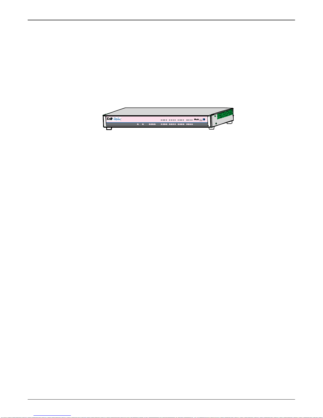
Figure 1-1: TA-2410/3010 Chassis
Capacity. TalkAnyTime
®
model TA3010 is a thirty-channel E1 unit (Euro digital telephony; 30 timedivision multiplexed channels on a single conductor) that can carry 30 simultaneous audio conversations.
The model TA2410 is a twenty-four-channel unit (US digital telephony; 24 time-division multiplexed
channels on a single conductor) that can carry 24 simultaneous audio conversations.. Both of these units
have a 10/100Mbps Ethernet interface, a local command port for local configuration using a Windows GUI,
and a remote configuration modem port for remote configuration using a Windows GUI. Both the TA2410
and the TA3010 are expandable to double capacity (from one to two T1/E1 lines) if an expansion card
(TA24-48 or TA30-60) is added.
XMTRCV XSGRSG
XMTRCV XSG RSG
XMTRCV XSG RSG
Mounting. Mechanically, the TA2410 and TA3010 units are designed for a one-high industry-standard EIA
19-inch rack enclosure. The product must be installed by qualified service personnel in a restricted-access
area, in accordance with Articles 110-16, 10-17, and 110-18 of the National Electrical Code, ANSI/NFPA 70.
Phone System Transparency. These TalkAnyTime units inter-operate with a telephone switch or PBX,
acting as a switching device that directs voice calls originating on an IP network into a PBX or key
telephone system. The TalkAnyTime units have “phonebooks,” directories that determine from whom calls
may be received. The TalkAnyTime unit can be set to give the caller a dial tone that allows her/him to dial
extensions within a PBX or key telephone system.
Management. Configuration and system management can be done locally or remotely with either of two
graphical user interfaces (GUIs). One is a Windows GUI and the other is a web-based GUI that operates
over the Internet or other IP network. After an IP address has been assigned with the Windows GUI, other
configuration can be done either locally or remotely using either the TalkAnyTime web browser GUI or its
Windows GUI. The Windows GUI is included on the Product CD; the web-based GUI is built into the
TalkAnytime unit at the factory and requires no installation.
8
Page 9
TalkAnytime User Guide Overview
While the web GUI’s appearance differs slightly, its contents and organization are essentially the same as
that of the Windows GUI.
9
Page 10
Overview TalkAnytime User Guide
The primary advantage of the web GUI is remote access for control and configuration. The controller PC
®
and the TalkAnyTime
unit itself must both be connected to the same IP network and their IP addresses
must be known.
10
Page 11
TalkAnytime User Guide Overview
Once you’ve begun using the web browser GUI, you can go back to the TalkAnyTime® Windows GUI at
any time. However, you must log out of the web browser GUI before using the TalkAnyTime
®
Windows
GUI.
Similarly, you must close the Windows GUI before opening the web GUI. The two GUIs cannot be used
simultaneously else a conflict or error will occur.
Logging of System Events. MultiTech has built SysLog Server functionality into the software of the
TalkAnyTime units. SysLog is a de facto standard for logging events in network communication systems.
The SysLog Server resides in the TalkAnyTime unit itself. To implement this functionality, you will need a
SysLog client program (sometimes referred to as a “daemon”). SysLog client programs, both paid and
freeware, can be obtained from Kiwi Enterprises, among other firms. See www.kiwisyslog.com
. SysLog
client programs essentially give you a means of structuring console messages for convenience and ease of
use.
MultiTech Systems does not endorse any particular SysLog client program. SysLog client programs by any
qualified provider should suffice for use with TalkAnyTime units. Kiwi’s brief description of their SysLog
program indicates the typical scope of such programs. “Kiwi Syslog Daemon is a freeware Syslog Daemon
for the Windows platform. It receives, logs, displays and forwards Syslog messages from hosts such as
routers, switches, Unix hosts and any other syslog enabled device. There are many customizable options
available.”
11
Page 12

Overview TalkAnytime User Guide
Digital TalkAnytime LED Descriptions
T1 Front Panel LEDs
The TA2410 and TA24-48 both use a common main circuit board or motherboard. Consequently the LED
indicators are the same for both.
Active LEDs. The TA2410 front panel has two sets of identical LEDs. In the TA2410 as shipped (that is,
without an expansion card), the left-hand set of LEDs is functional whereas the right-hand set is not.
When the TA2410 has been upgraded with an TA24-48 kit, the right-hand set of LEDs will also become
active.
Click-to-Talk Media Server
Figure 1-2: TA2410 LEDs
T1 LED Descriptions. The descriptions below apply to the digital T1 TalkAnytime units. The TA2410 has
two sets of LEDs, one for the single board shipped inside the TA2410 unit, and a second set for an
expansion board that can be purchased (TA24-48). As viewed from the front of the TA2410, it is the left
group that is active and that presents feedback about the operation of the TA-2410 unit. If a TA24-48
expansion card is added to the TA2410, the second group of LEDs, beginning with the second “Power”
LED, become operational with respect to the second T1 TalkAnytime circuit card.
12
Page 13

TalkAnytime User Guide Overview
T1 LED Descriptions
TA2410 Front Panel LED Definitions
LED NAME DESCRIPTION
Power Indicates presence of power.
Boot
After power up, the Boot LED will be on for about 10
seconds while the TA2410 is booting.
LNK Link/Activity LED. This LED is lit if Ethernet
connection has been made. It is off when the link is
down (i.e., when no Ethernet connection exists). While
link is up, this LED will flash off to indicate data
activity.
FDX Full-Duplex & Collision LED. This LED indicates
whether the Ethernet connection is half-duplex or fullduplex (FDX) and, in half-duplex mode, indicates
occurrence of data collisions. LED is on constantly for
full-duplex mode; LED is off constantly for half-duplex
mode. When operating in half-duplex mode, the LED
will flash during data collisions.
T1 Indicates that the unit is a T1 TalkAnytime model.
E1 E1. Not supported.
PRI PRI. On if T1 line is of ISDN-Primary-Rate type.
ONL Online. This LED is on when frame synchroni-
zation has been established on the T1/E1 link.
IC IC LED is on when Internal Clocking is selected in
T1/E1 configuration.
LC Indicates Loss of Carrier.
LS Indicates Loss of Signal.
Test For testing purposes only.
13
Page 14

Overview TalkAnytime User Guide
E1 Front Panel LEDs
The TA3010 and TA30-60 both use a common main circuit card or motherboard. Consequently, the LED
indicators are the same for both.
Click-to-Talk Media Server
Figure 1-4: TA3010 LEDs
Active LEDs. The TA3010 front panel has two sets of identical LEDs. In the TA3010 as shipped (that is,
without an expansion card), the left-hand set of LEDs is functional whereas the right-hand set is not.
When the TA3010 has been upgraded with an TA30-60 kit, the right-hand set of LEDs will also become
active.
14
Page 15

TalkAnytime User Guide Overview
E1 LED Descriptions
TA3010 Front Panel LED Definitions
LED NAME DESCRIPTION
Power Indicates presence of power.
Boot After power up, the Boot LED will be on for
about 10 seconds while the TA3010 is booting.
LNK Link/Activity LED. This LED is lit if Ethernet
connection has been made. It is off when the link is
down (i.e., when no Ethernet connection exists).
While link is up, this LED will flash off to indicate data
activity.
FDX Full-Duplex & Collision LED. This LED indicates
whether the Ethernet connection is half-duplex or fullduplex (FDX) and, in half-duplex mode, indicates
occurrence of data collisions. LED is on constantly for
full-duplex mode; LED is off constantly for halfduplex mode. When operating in half-duplex mode,
the LED will flash during data collisions.
T1 T1. Not supported (see below).
E1 E1. When lit, indicates that unit is configured for
E1 operation. It is possible for the TA3010 to be
internally re-configured for T1 operation.
However, this is not recommended because this
change would leave one of the unit’s five
primary circuitry sub-units unused. If T1
operation is desired, it is far more efficient to use
a TA2410 unit than to re-configure the TA3010
unit.
PRI PRI. On if E1 line is of ISDN-Primary-Rate type.
ONL Online. This LED is on when frame
synchronization has been established on the
T1/E1 link.
IC IC LED is on when Internal Clocking is selected
in T1/E1 configuration.
LC Indicates Loss of Carrier.
LS Indicates Loss of Signal.
Test For testing purposes only.
15
Page 16

Overview TalkAnytime User Guide
Command Computer Requirements
The computer on which the TalkAnytime unit’s configuration program is installed must meet these
requirements:
• must be IBM-compatible PC with MS Windows operating system;
• must have an available COM port for connection to the TalkAnytime unit (or, for computers
with USB2.0 ports but lacking serial ports, the computer must be fitted with a USB2.0-toserial adapter);
• must be connected to your local network (Ethernet) system, and
• must have an available serial COM port (or USB2.0 port if applicable).
However, this PC does not need to be connected to the TalkAnytime unit permanently. It only needs to be
connected when local configuration and monitoring are done. After an IP address for the TalkAnytime unit
has been set with the Windows GUI, all configuration and monitoring functions can be done remotely via
the IP network (using the TalkAnytime web GUI) on any computer that can run a modern web browser.
Work-Around Allowing Use of Web GUI Only. The default IP address of the TalkAnytime unit as
shipped from the factory is 192.168.3.143. By installing the up-to-date Java program from the TalkAnytime
CD and temporarily resetting the IP address of the command computer to 192.168.3.x, the TalkAnytime
unit’s built-in- web GUI can be contacted and its IP address can be set as needed. If this is done, all
subsequent configuration can be done using the TalkAnytime web GUI and the command computer would
not need a serial COM port. However, under such an arrangement, the command computer would remain
unable to use the TalkAnytime Windows GUI because contact with the Windows GUI requires either a
COM port or the USB2.0-to-serial adaptor arrangement.
Client Computer Requirements
To make an incoming call using TalkAnytime, the computer must meet the requirements described in the
table below.
Category Requirement
Operating System Windows 98 or Windows XP
Browser Internet Explorer 5.0 or higher
Audio Hardware Microphone & Speaker (in any form)
O.S. Settings Headset or microphone/speaker combo
must be activated and not pre-empted by
any other audio hardware or software.
Browser Settings Popup Blocking must be disabled at least
for the IP address at which the
TalkAnytime unit is operating.
Activex controls must be enabled.
In terms of audio hardware, many combinations are possible. In any event, the computer must have both a
microphone and an audio output device and they must be activated. A headset that includes both a
microphone and a speaker (connected to the appropriate jacks on the computer’s sound card) would meet
this requirement. The computer might have a built-in microphone and built-in or extension speakers and
such a combination would also meet this requirement.
16
Page 17

TalkAnytime User Guide Overview
Specifications
Specs for Digital T1 TalkAnytime Units
Digital T1 TalkAnytime Specifications
Parameter
……/Model
Operating
Voltage/Current
Mains
Frequencies
Power
Consumption
Mechanical
Dimensions
Weight
TA2410
100-240 VAC
1.2 - 0.6 A
50/60 Hz 50/60 Hz
17 watts 27 watts
1.75”H x
17.4”W x
8.75”D
4.5cm H x
44.2 cm W x
22.2 cm D
7.1 lbs.
(3.2 kg)
TA2410
w/ TA24-48
Expansion
Card
100-240 VAC
1.2 - 0.6 A
1.75”H x
17.4”W x
8.75”D
4.5cm H x
44.2 cm W x
22.2 cm D
7.5 lbs.
(3.4 kg)
17
Page 18

Overview TalkAnytime User Guide
Specs for Digital E1 TalkAnytime Units
Digital E1 TalkAnytime Specifications
Parameter
……/Model
Operating
Voltage/Current
Mains
Frequencies
Power
Consumption
Mechanical
Dimensions
Weight
TA3010 TA3010
w/ TA30-60
Expansion
Card
100-240 VAC
1.2 - 0.6 A
100-240 VAC
1.2 - 0.6 A
50/60 Hz 50/60 Hz
17 watts 27 watts
1.75”H x
17.4”W x
8.75”D
4.5cm H x
44.2 cm W x
22.2 cm D
7.1 lbs.
(3.2 kg)
1.75”H x
17.4”W x
8.75”D
4.5cm H x
44.2 cm W x
22.2 cm D
7.5 lbs.
(3.4 kg)
Installation at a Glance
The basic steps of installing your TalkAnytime unit involve
• unpacking the unit,
• connecting the cables,
• configuring it using management software (TalkAnytime Configuration software),
• making phonebook entries to determine routing of incoming calls,
• establishing a TalkAnytime URL that includes certain operating parameters
and placing a link to that URL on a website, and
• confirming connectivity on an incoming call.
This process results in a fully functional click-to-talk system.
18
Page 19

TalkAnytime User Guide Overview
Related Documentation
The TalkAnytime User Guide (the document you are now reading) comes in electronic form and is included
on your system CD. It presents in-depth information on the features and functionality of Multi-Tech’s
digital TalkAnytime products. Chapter 2 of this manual consists of “Quick Start Instructions” meant to get
the product up and running quickly with a simple configuration.
A printed Cabling Guide is also included with the product. Its purpose is to help get the unit’s cables
connected properly.
The CD media is produced using Adobe Acrobat
print your copy of a user guide, load Acrobat Reader
a free download from Adobe’s Web Site (below) and the TalkAnytime CD has a link to that site.
TM
for viewing and printing the user guide. To view or
TM
on your system. The Acrobat Reader is available as
www.adobe.com/prodindex/acrobat/readstep.html
This TalkAnytime User Guide is also available on Multi-Tech’s Web site at:
http://www.multitech.com
Viewing and printing a user guide from the Web also requires that you have the Acrobat Reader loaded on
your system. To select the TalkAnyTime User Guide from the Multi-Tech Systems home page, click Documents and then
click TalkAnytime in the product list drop-down window. All TalkAnyTime documents will be displayed. You can then
choose User Guide to view or download the .pdf file.
The TalkAnytime CD also includes, as PDF files, single-page descriptions for end-users about how to use TalkAnytime. One
document pertains to calls directed to a phone pool. A second document pertains to incoming calling where the caller can, after
connection, dial specific extensions within the organization’s PBX. A third document pertains to use of the TalkAnytime by
trusted parties who are allowed full access to the PBX including PSTN access.
Entries (organized by model number) in the “knowledge base” and ‘troubleshooting resolutions’ sections of
the MultiTech web site (found under “Support”) constitute another source of help for problems
encountered in the field.
19
Page 20

Chapter 2: Quick Start Instructions
20
Page 21

TalkAnytime Quick Start Instructions Gathering Phone/IP Details
Introduction
This chapter will get your TalkAnytime up and running quickly.
More detailed treatment of setup topics can be found in the “Technical Configuration” and “Phonebook
Configuration” chapters of this manual.
Safety Warnings
Lithium Battery Caution
A lithium battery on the voice/fax channel board provides backup power for the timekeeping capability.
The battery has an estimated life expectancy of ten years.
When the battery starts to weaken, the date and time may be incorrect. If the battery fails, the board must
be sent back to Multi-Tech Systems for battery replacement.
Warning: There is danger of explosion if the battery is incorrectly replaced.
Safety Warnings Telecom
1. Never install telephone wiring during a lightning storm.
2. This product must be disconnected from power source and telephone network interface when servicing.
3. This product is to be used with UL and cUL listed computers.
4. Never touch uninsulated telephone wires or terminals unless the telephone line has been disconnected at
the network interface.
5. Use caution when installing or modifying telephone lines.
6. Avoid using a telephone (other than a cordless type) during an electrical storm. There may be a remote
risk of electrical shock from lightning.
7. Do not use a telephone in the vicinity of a gas leak – not even to report a gas leak.
8. To reduce the risk of fire, use only a UL-listed 26 AWG or larger telecommunication line cord.
9. Never install a telephone jack in a wet location unless the jack is specifically designed for wet locations.
21
Page 22

TalkAnytime Quick Start Instructions Startup Tasks
TalkAnytime Startup Tasks
Task Summary
Collecting Phone/IP
Details ( vital! )
Placement
Command/Control
Computer Setup:
Specs & Settings
The TalkAnytime must be configured to
interface with your particular phone
system and IP network. To do so,
certain details must be known about
those phone and IP systems.
Decide where you’ll mount the unit.
Some modest minimum specifications
must be met. A data connection to the
TalkAnytime unit (whether via serial
port, USB2.0-with-adaptor, or webbased) must be made.
Hookup Connect power, ground, phone, and
data cables per diagram.
Software Installation This is the configuration program.
It’s a standard Windows software
installation.
Phone/IP Starter
Configuration
Phonebook/URL Starter
Configuration
You will enter phone numbers and IP
addresses. You’ll use default parameter
values where possible to get the system
running quickly.
Use “Config Info CheckList” (page 26).
The phonebook is where you specify
how calls will be routed. A special URL
determines how the TalkAnytime will
interact with your web server.
Connectivity Test You’ll find out if your TalkAnytime
system can receive phone calls from
visitors to your web site. That means
you’re up and running!
Troubleshooting Detect and remedy any problems that
might have prevented connectivity.
22
Page 23
TalkAnytime Quick Start Instructions Gathering Phone/IP Details
Phone/IP Details *Absolutely Needed*
Before Starting the Installation
The TalkAnytime will interface with both the IP network and the phone system. You must gather
information about the IP network and about the phone system so that the TalkAnytime can be configured
to operate with them properly. A summary of this configuration information appears on page 26 (“Config
Info CheckList”).
Gather IP Information
Ask your computer network
administrator.
#
• IP Address
Note: The default IP address of TalkAnytime units
is 192.168.3.143.
• IP Mask
• Gateway
• Domain Name Server (DNS) Info (optional)
• Determine whether or not 802.1p Packet Prioritization
will be used.
IP Network Parameters:
Record for this
TalkAnytime unit.
T1 Telephony Parameters (for TA2410)
The following parameters must be known about the PBX or telco central office equipment to which the T1
TalkAnytime unit will connect:
T1 Phone Parameters
Ask phone company or
PBX maintainer.
Info needed to operate:
TA2410
#
• Which frame format is used?
• Which CAS or PRI protocol is used? ______________
• Clocking: Does the PBX or telco switch use
internal or external clocking? _________________
Note that the setting used in the TalkAnytime unit will
be the opposite of the setting used by the telco/PBX.
• Which line coding is used?
Write down the values for these T1 parameters. You will need to enter these values in the “T1/E1/ISDN
Parameters” screen in the Configuration section of the TalkAnytime software.
T1 Parameters:
Record for this
TalkAnytime unit.
ESF___ or D4___
AMI___ or B8ZS___
23
Page 24

Gathering Phone/IP Details TalkAnytime Quick Start Instructions
E1 Telephony Parameters (for TA3010)
The following parameters must be known about the PBX or telco central office equipment to which the E1
TalkAnytime unit will connect:
E1 Phone Parameters
Ask phone company or
PBX maintainer.
#
• Which frame format is used?
• Which CAS or PRI protocol is used? ______________
• Clocking: Does the PBX or telco switch use
internal or external clocking? _________________
Note that the setting used in the TalkAnytime unit will
be the opposite of the setting used by the telco/PBX.
• Which line coding is used?
• Pulse shape level?: (most commonly 0 to 40 meters)
Write down the values for these E1 parameters. You will need to enter these values in the “T1/E1/ISDN
Parameters” screen in the Configuration section of the TalkAnytime software.
E1 Parameters:
Record for this
TalkAnytime unit.
MultiFrame w/ CRC4 modified_____
Info needed to operate:
TA3010
Double Frame_____
MultiFrame w/ CRC4_____
AMI___ or HDB3___
24
Page 25
TalkAnytime Quick Start Instructions Gathering Phone/IP Details
Phone/IP Details Often Needed/Wanted
Obtain Email Address for TalkAnytime
(for email call log reporting)
required if log reports of
TalkAnytime call traffic
are to be sent by email
SMTP Parameters
Preparation Task:
Ask Mail Server
administrator to set up
email account (with
password) for the
TalkAnytime unit itself.
Be sure to give a unique
identifier to each
individual TalkAnytime
unit.
Get the IP address of the
mail server computer, as
well.
Optional
To: I .T. De par tmen t
re: email accoun t for VOIP
voip-unit2@biggytech.com
25
Page 26

Gathering Phone/IP Details TalkAnytime Quick Start Instructions
Config Info CheckList
Type of Config Info Gathered TalkAnytime
Configuration screen
on which to enter
Config Info
√
IP info for TalkAnytime unit
● IP address
● Gateway
● DNS IP (if used)
● 802.1p Prioritization (if used)
Frame Format
(Choices: ESF, D4, F4, SLC96)
Frame Format
(Choices: Double Frame, Multi-Frame w/
CRC4, Multi-Frame w/ CRC4 Modified)
CAS Protocol
(Choices: FXS Loop Start, E&M Wink,
E&M Wink w/ Dial Tone, FXO Ground
Start, FXO Loop Start, FXS Ground Start,
E&M Immediate, MFR2-China, Clear
Channel)
ISDN-PRI Protocol
(only if ISDN-PRI is used)
(Choices: Network, Terminal)
Clocking
(Choices: Internal, External)
Line Coding
(Choices: AMI, B8ZS)
Pulse Shape Level
(Choices: 0 – 40 m)
Country Code Regional Parameters
Email address for voip
(optional)
Reminder: Be sure to Save Setup after entering configuration values.
Ethernet/IP Parameters
T1/E1/ISDN Parameters
(TA2410 only)
T1/E1/ISDN Parameters
(TA3010 only)
T1/E1/ISDN Parameters
T1/E1/ISDN Parameters
T1/E1/ISDN Parameters
T1/E1/ISDN Parameters
T1/E1/ISDN Parameters
SMTP Parameters
26
Page 27

Placement & Command PC Settings TalkAnytime Quick Start Instructions
Placement
Mount your TalkAnytime unit in a safe and convenient location where cables for your network and phone
system are accessible. Rack-mounting instructions are in Chapter 3: Mechanical Installation & Cabling of the
User Guide.
Command/Control Computer Setup (Specs & Settings)
The computer used for command and control of the TalkAnytime
(a) must be an IBM-compatible PC,
(b) must use a Microsoft operating system,
(c) must be connected to your local network (Ethernet) system, and
(d) must have an available serial COM port.
The configuration tasks and control tasks the PC will have to do with the TalkAnytime are not especially
demanding. Still, we recommend using a reasonably new computer. The computer that you use to
configure your TalkAnytime need not be dedicated to the TalkAnytime after installation is complete.
COM port on controller PC. You’ll need an available COM port on the controller PC. You’ll need to know
which COM port is available for use with the TalkAnytime (COM1, COM2, etc.). If your command
computer has only USB2.0 ports and no serial ports, you will need a USB2.0-to-serial adaptor.
Work-Around Allowing Use of Web GUI Only. The default IP address of the TalkAnytime unit as
shipped from the factory is 192.168.3.143. By installing the up-to-date Java program from the TalkAnytime
CD, temporarily resetting the IP address of the command computer to 192.168.3.x, and connecting both to
the same physical Ethernet network, the TalkAnytime unit’s built-in- web GUI can be contacted and its IP
address can be set as needed. If this is done, all subsequent configuration can be done using the
TalkAnytime web GUI and the command computer would not need a serial COM port. Therefore, in the
case of a computer lacking a serial port, no USB2.0-to-serial adaptor would be needed. However, under
such an arrangement, the command computer would remain unable to use the TalkAnytime Windows GUI
because contact with the Windows GUI requires either a COM port or the USB2.0-to-serial adaptor
arrangement. (If you use this work-around, you must be sure to re-set your command PC to its original IP
address afterwards.)
27
Page 28

Quick Hookup TalkAnytime Quick Start Instructions
Client Computer Requirements
To make an incoming call using TalkAnytime, the computer must meet the requirements described in the
table below.
Category Requirement
Operating System Windows 98 or Windows XP
Browser Internet Explorer 5.0 or higher
Audio Hardware Microphone & Speaker (in any form)
O.S. Settings Headset or microphone/speaker combo
must be activated and not pre-empted by
any other audio hardware or software.
Browser Settings Popup Blocking must be disabled for the
IP address of the TalkAnytime unit.
(Popup Blocking need not be disabled
globally.)
Activex controls must be enabled.
In terms of audio hardware, many combinations are possible. In any event, the computer must have both a
microphone and an audio output device and they must be activated. A headset that includes both a
microphone and a speaker (connected to the appropriate jacks on the computer’s sound card) would meet
this requirement. The computer might have a built-in microphone and built-in or extension speakers and
such a combination would also meet this requirement.
End-User Information
This chapter documents three ways in which the TalkAnytime unit could make toll-free calling available for
end-users. On the Product CD, we present descriptions of these three applications in separate, single-page
files to explain these applications to end-users. We intend that these files be made available by hyper-link
from the web page at which end-users will access TalkAnytime. The files are listed below.
● TalkAnytime Client Pool-Call Primer
● TalkAnytime Client Specific-Extension Primer
● TalkAnytime Client Dial-Thru Primer
28
Page 29
TalkAnytime Quick Start Instructions Client PC Requirements
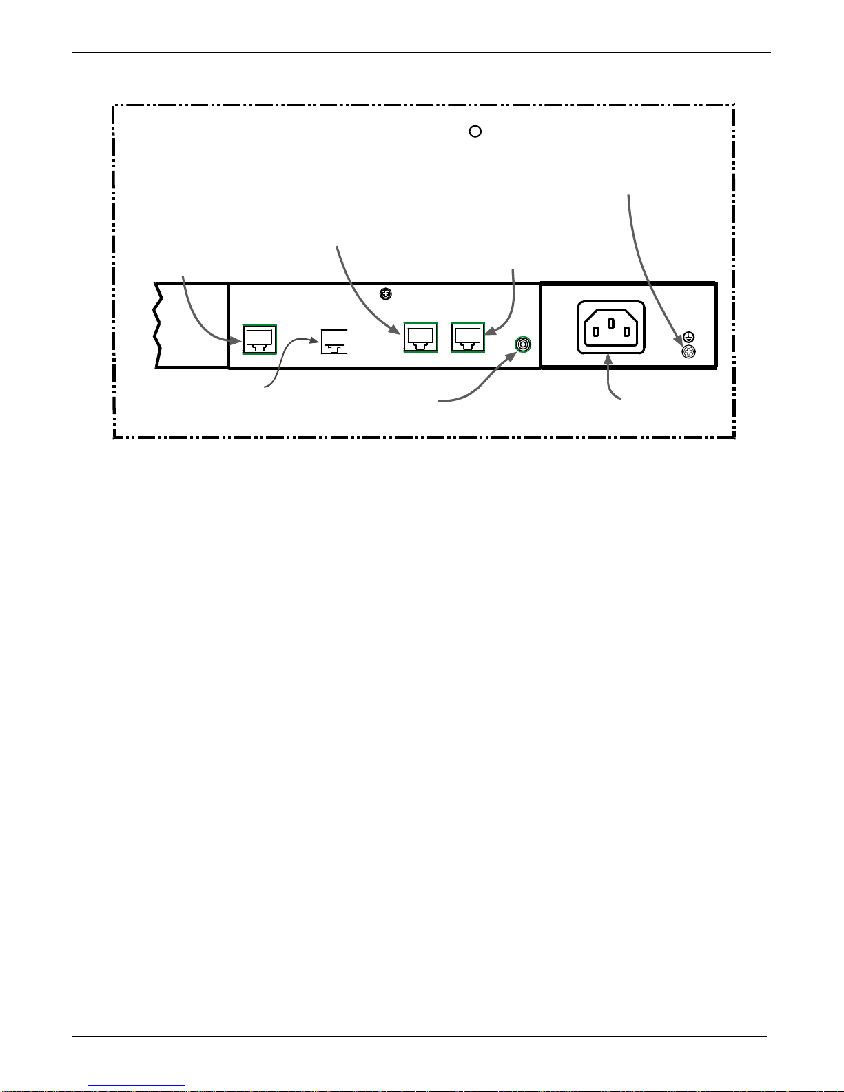
Quick Hookup for TA2410 & TA3010
T1/E1/PRI cabling
to your PBX.
RJ-45 connector.
Cabling to POTS line
(RJ-11 connector) for remote
configuration via the built-in
modem.
T1/E1 TalkAnytime Hookup
R
(TA-2410/3010)
Cabling to your IP network.
RJ-45 connector.
DIGITAL VOICE
TRUNK O
COMMAND
MODEM
On/Off Switch
WAN
Cabling to computer running
TalkAnytime software.
RJ-45 to serial connector (DB9).
CONSOLE
Grounding
Screw
l
Power Cable
Receptacle
29
Page 30

TalkAnytime Quick Start Instructions Software Installation
Install TalkAnytime Configuration Software onto Command PC
For more details, see Chapter 4: Software Installation in User Guide.
1. TalkAnytime unit must be properly cabled. Power must be turned on.
2. Insert TalkAnytime CD into drive. Allow 10-20 seconds for Autorun to start. If Autorun fails, go to
My Computer | CD ROM drive | Open. Click Autorun icon.
3. At first dialog box, click Install Software.
4. At ‘welcome’ screen, click Next.
5. Follow on-screen instructions. Accept default program folder location and click Next.
6. Accept default icon folder location. Click Next. Files will be copied.
7. At completion screen, click Finish.
8. At the prompt “Do you want to run TalkAnytime Configuration?,” click No. Software installation is
complete.
30
Page 31

TalkAnytime Quick Start Instructions Phone/IP Starter Config.
Phone/IP Starter Configuration
Full details here: Technical Configuration chapter in User Guide
1. Open the TalkAnytime program:
Start | TalkAnytime xxx | Configuration.
Note: If you used the “Work-Around” on page 27 to operate using the TalkAnytime web GUI only, skip to step 4E.
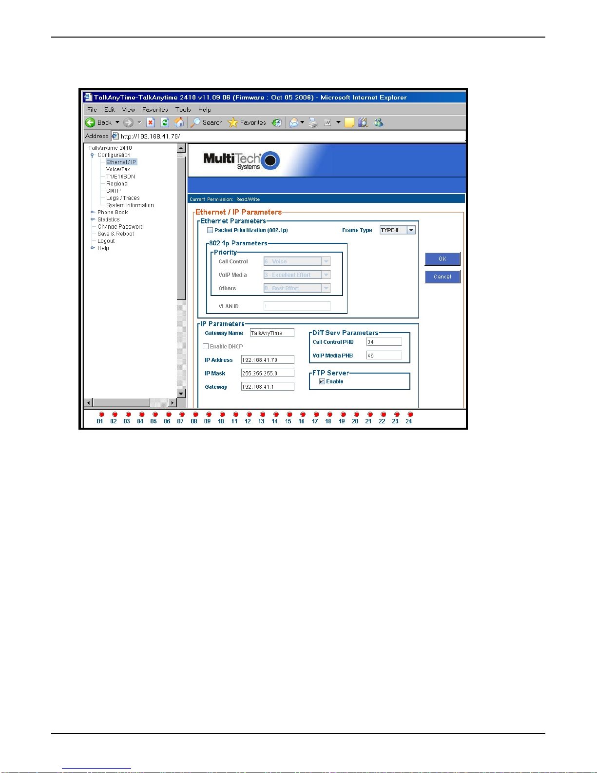
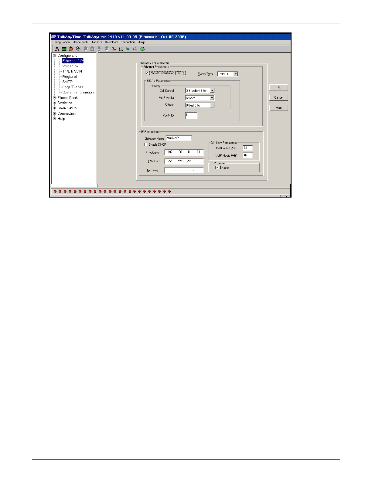
2. Go to Configuration | Ethernet/IP. Enter the IP parameters for your TalkAnytime unit. Activate Packet
Prioritization (802.1p) if desired. For details, see the “Technical Configuration” chapter of the User Guide.
3. Do you want to configure and operate the TalkAnytime unit using the web browser GUI? (It has the
same functionality as the local Windows GUI, but offers remote access.)
If NO, skip to step 5. If YES, continue with step 4.
4. Web Browser GUI Setup (Optional). To do configuration and operation procedures using the web
browser GUI, you must first set it up. To do so, follow these steps. (The browser used must be Internet
Explorer 6.0 or above; or Netscape 6.0 or above; or FireFox 1.0 or above.)
A. Be sure an IP address has been
assigned to the TalkAnytime unit
(this must be done in the
TalkAnytime Windows GUI).
B. Save Setup in Windows GUI. F. Browse to IP address of
C. Close the TalkAnytime Windows
GUI.
D. Install Java program from
TalkAnytime product CD.
(Must be Java Runtime
Environment 1.4.2_01 or above.)
NOTE: Required on first use of
Web Browser GUI only.
Need more
info?
See “Web Browser Interface” in Operation &
Maintenance chapter of User Guide (on CD).
E. Open web browser.
(Note: The PC being used must
be connected to and have an IP
address on the same IP network
that the TalkAnytime is on.)
TalkAnytime unit.
G. If username and password have
been established, enter them
when prompted by the
TalkAnytime unit.
H. Use web browser GUI to
configure or operate the
TalkAnytime unit.
Once you’ve begun using the web browser GUI, you can go back to the TalkAnytime Windows GUI
at any time. However, you must log out of the web browser GUI before using the TalkAnytime
Windows GUI.
5. Go to Configuration | Voice/Fax. Select Coder | “Automatic.” At the right-hand side of the dialog box,
click OK. If you know any specific parameter values that will apply to your system, enter them. Click
Copy Channel. Select Copy to All. Click Copy. At main Voice/Fax Parameters screen, click OK to exit
from the dialog box.
6. Enter telephone system information.
Go to Configuration | T1/E1/ISDN Parameters. Enter parameters obtained from phone company or PBX
administrator.
7. Go to Configuration | Regional Parameters. Select the Country/Region that fits your situation. Click
OK and confirm. Click OK to exit from the dialog box.
31
Page 32

Phone/IP Starter Config. TalkAnytime Quick Start Instructions
Phone/IP Starter Configuration (continued)
8. Go to Configuration | Regional Parameters. In the Country Selection for Built-In Modem field (drop-
down list), select the country that best fits your situation. (This may not be the same as your selection for
the Country/Region field. The selections in the Country Selection for Built-In Modem field entail more
detailed groupings of telephony parameters than do the Country/Region values.) Click OK.
9. Do you want the phone-call logs produced by the TalkAnytime to be sent out by email (to your
Administrator or someone else)?
If NO, skip to step 11.
If YES, continue with step 10.
10. Go to Configuration | SMTP.
SMTP lets you send phone-call log records to the TalkAnytime Administrator by email. Select Enable
SMTP.
You should have already obtained an email address for the TalkAnytime itself (this serves as the
origination email account for email logs that the TalkAnytime can email out automatically).
Enter this email address in the “Login Name” field.
Type the password for this email account. Click OK.
Enter the IP address of the email server where the TalkAnytime’s email account is located in the “Mail
Server IP Address” field.
Typically the email log reports are sent to the TalkAnytime Administrator but they can be sent to any
email address. Decide where you want the email logs sent and enter that email address in the “Recipient
Address” field.
Whenever email log messages are sent out, they must have a standard Subject line. Something like
“Phone Logs for TalkAnytime N” is useful. If you have more than one TalkAnytime unit in the building,
you’ll need a unique identifier for each one (select a useful name or number for “N”). In this “Subject”
field, enter a useful subject title for the log messages.
In the “Reply-To Address” field, enter the email address of your Administrator.
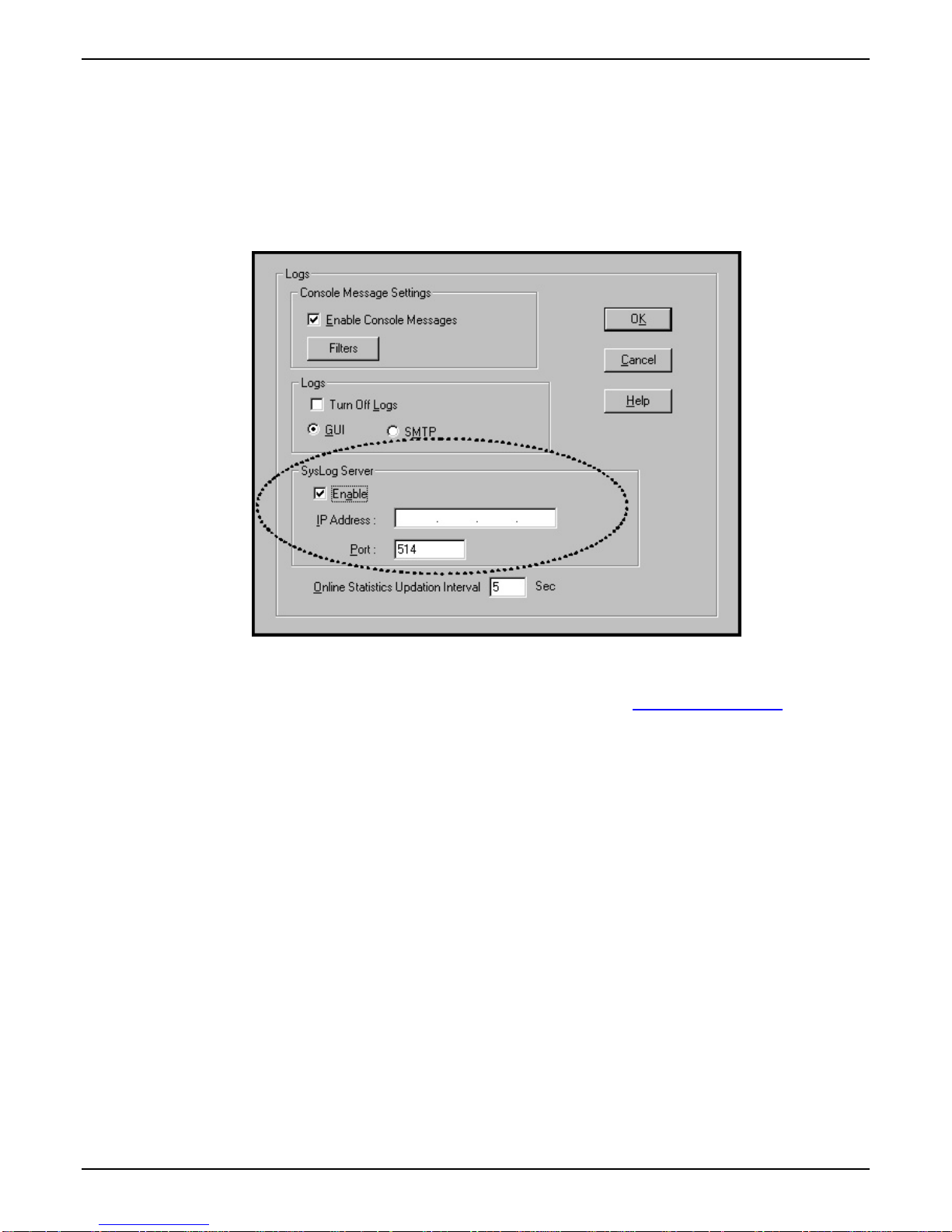
11. Go to Configuration | Logs.
Select “Enable Console Messages.”
To allow log reports by email (if desired), click SMTP. Click OK.
To do logging with a SysLog client program, click on “SysLog Server – Enable” in the Logs screen. To
implement this function, you must install a SysLog client program. For more info, see the “SysLog Server
Functions” section of the Operation & Maintenance chapter of the
User Guide.
12. Go to Save Setup | Save and Reboot. Click OK. This will save the parameter values that you have just
entered.
The TalkAnytime unit’s “BOOT” LED will light up while the configuration file is being saved and loaded
into the TalkAnytime. Don’t do anything to the TalkAnytime until the “BOOT “LED is off (a loss of
power at this point could cause the TalkAnytime unit to lose the configuration settings you have made).
END OF PROCEDURE.
32
Page 33

TalkAnytime Quick Start Instructions Phonebook Configuration
Inbound Phonebook
1. Open the TalkAnytime program.
( Start | TalkAnytime xxx | Configuration )
2. Go to Phone Book | Inbound Phonebook | Add Entry.
3. In the “Remove Prefix” field, enter the PBX extension to which you want to direct the incoming
TalkAnytime calls.
4. In the “Add Prefix” field, enter the same digits as were entered in the “Remove Prefix” field.
5. In the “Channel Number” field, enter “Hunting.” A “hunting” value means the TalkAnytime unit will
assign the call to the first available channel.
If desired, specific channels can be assigned to specific incoming calls (i.e., to any set of calls received
with a particular incoming dialing pattern).
6. In the “Description” field, enter an identifier (letters and/or digits) that describes the destination of the
incoming TalkAnytime calls. The identifier entered in this field must match the identifier used in the
Service field of the TalkAnytime URL (see the “TalkAnytime URL Configuration” section below). The
description should make the routing of calls easy to understand. (40 characters max.)
7. Repeat steps 2-6 for each inbound phonebook entry. As noted above, each channel of the TalkAnytime
unit can be configured separately, have its own values in the “Remove Prefix” and “Add Prefix” fields
and its own “Description” value. Or all channels can be configured alike. When all entries are complete,
go to step 8.
8. Click OK to exit the inbound phonebook screen.
9. Click on Save Setup. Highlight Save and Reboot. Click OK.
Your starter inbound phonebook configuration is complete.
33
Page 34

URL Configuration TalkAnytime Quick Start Instructions
TalkAnytime URL Configuration
End users will access the TalkAnytime by clicking on an icon on a web site. The web server must include a
URL link expression that not only directs the caller to the TalkAnytime unit but also specifies values for
several other parameters (four parameters are required; two are optional).
The general form of the URL expression is as follows:
TalkAnytime URL Command Line
http://a.b.c.d/tat.cgi?Service=string1&Protocol=n&Codec=q&SC=w
&Packetization=y&Digits=z
Configuration
Parameter
Involved
TalkAnytime
IP Address
Portion of URL in
question
where a, b, c, and d are
the IP address octet
numbers;
Values: 0 to 255
Service where string1 is a variable;
Values: any
letters/numbers;
no spaces, periods,
commas, or symbols;
40 characters max.
Protocol where n is a variable;
Values: TCP or UDP
Codec where q is a variable;
Values: G711A, G711U,
G723
Silence
Compression
where w is a variable;
Values: ON, OFF
Comment
This value must match the
value of the Description
field in the Inbound
Phonebook.
Optional parameter. If
omitted, remove the entire
expression “&SC=w” from
URL.
34
Page 35

TalkAnytime Quick Start Instructions URL Configuration
TalkAnytime URL Command Line (cont’d)
http://a.b.c.d/tat.cgi?Service=string1&Protocol=n&Codec=q&SC=w
&Packetization=y&Digits=z
Configuration
Parameter
Involved
Packetization where y is a variable;
Portion of URL in question Comment
Optional parameter. If omitted,
Values: 30, 60, 90, & 120 (for G723);
10, 20, 30, 40, 50, 60, 70, 80,
remove the entire expression
“&Packetization=y” from URL.
& 90 (for G711A & G711U).
Digits where z is a variable;
Values: Yes, No
allowed variant
tatfrm.cgi? Eliminates black background
of tat.cgi?
Note: All non-italicized characters in the URL
expression are fixed literal characters that
must be included verbatim. As noted
above, the tat.cgi? expression has an
allowed variant.
When Digits=No, the end user
can use the TalkAnytime
keypad to dial only after
connection has been made.
When Digits=Yes, TalkAnytime
keypad is available
immediately.
behind TalkAnytime user
screen.
Use of phonebook entries and URL command lines is illustrated in the
that follows.
TalkAnytime System Examples section
35
Page 36

End-User’s Perspective TalkAnytime Quick Start Instructions
TalkAnytime System Examples
Introduction
The following example shows how the TalkAnytime unit operates in a specific telecommunications system.
Home PC User A
Command PC
Whirlygig Gad get
Company Office s
Ethernet LAN
Talk
Anytime
TA2410
T1
Internet
PBX
Web Server
PSTN
IVR
x8651
Comblasti cator
Specialist
MI C
SPKR
Home PC User B
Customer
Service
Dept.
Traveling
Whirlygig
Manager
x8652
Zanfraditron
Specialist
x8653
Fridnorpulizer
Spec ia list
x86 54
Gronplostramax
Spe cialist
In this system, the TalkAnytime unit is connected to a PBX system. Incoming calls are directed to two
different departments, the Sales Department (where all call recipients are peers and it is satisfactory for the
incoming caller to reach any one of them) and the Customer Service Department (where each call recipient
is a specialist). We show 3 callers. Two are customers; the computer of one is equipped with a
microphone/speaker headset; the computer of the other has external speakers and an external microphone.
The third caller is an employee of the Whirlygig Gadget Company, a trusted party who has instructions on
how to use the TalkAnytime unit to reach the public phone system (PSTN) as well as other Whirlygig
employees through the PBX.
x7301
Sales
Dept.
x73 02
x73 03
Example Types. We will show a configuration of TalkAnytime settings that allows 3 different types of calls:
(a) calls into a phone pool,
(b) calls directed to specific individual phones through an IVR (a voice recording device connected
to a PBX and that plays a recorded message and allows callers to dial different extensions with
DTMF signals from phone or keypad), and
(c) calls by a trusted party into an institutional PBX and out into the local public phone system
(PSTN).
36
Page 37

TalkAnytime Quick Start Instructions End-User’s Perspective
Calls into a Phone Pool
User-A Calls Sales Department. The drawing below shows a call coming into the Whirlygig Sales
Department from a prospective customer. The PBX is set up to ‘hunt’ among a group of extensions allotted
to the Sales Department. The TalkAnytime unit directs calls originating through the Whirlygig web server
to the PBX and into the phone pool of sales representatives.
The main settings of the TalkAnytime Configuration Program, Phonebook, and web server URL that are
required to implement this capacity are shown in the second drawing below. Note that, especially for the
T1/E1/ISDN parameters, your settings must simply conform to the requirements of your PBX; there is no
set of routine default values that can be depended upon to be widely applicable.
Home PC User A
65.129.90.200
Call
starts
here.
Internet
Whirlygig Gadget
Company Offices
Path of Call
Web Server
Ethernet LAN
x8651
Comblasticator
Specialis t
Zanfraditron
Spec ialist
Customer
Service
Dept.
IVR
x8652
x8653
Fridnorpulizer
Specialist
Talk
Anytime
TA2410
466-0000
x7301
x7302
Sales
Dept.
PBX
717-
T1
PBX is
set to ‘hunt’
among
extensions
7300-7399.
PSTN
x7303
Gronplostramax
37
x8654
Specialis t
Page 38

End-User’s Perspective TalkAnytime Quick Start Instructions
Technical Configuration for Phone Pool Call
38
Page 39

TalkAnytime Quick Start Instructions End-User’s Perspective
Calls to Specific Extensions Through an IVR
User-B Calls Customer Service Specialist. The drawing below shows a call coming into a particular
product specialist in the Whirlygig Customer Service Department from customer concerned about a
“Zanfraditron” device (a fictional product contrived for this example). The PBX is equipped with an IVR
(which produces outgoing messages and allows DTMF in return from the caller) at extension 8600. In
response to the outgoing message, the caller dials the desired extension for the Zanfraditron specialist on
the TalkAnytime keypad and the connection is made.
The main settings of the TalkAnytime Configuration Program, Phonebook, and web server URL that are
required to allow this kind of incoming call are shown in the second drawing below. Note that, especially
for the T1/E1/ISDN parameters, your settings must simply conform to the requirements of your PBX;
there is no set of routine default values that can be depended upon to be widely applicable.
Whirlygig Gadget
Company Offices
65.129.90.200
Ta lk
T1
Anytime
TA2410
PBX
717-
466-0000
PBX is set
to route calls
to 8600 to IVR.
Internet
Path of Call
IVR’s Outgoing Message
“Welcome to W hirlygig.....
To speak to a Zanfraditron
specialist, dial 8652.”
Ethernet LAN
Web Server
IVR
ext 8600
Call
starts
here.
MIC
SPKR
Home PC User B
After hearin g IVR’s outg oing message,
caller uses TalkAnytime keypad to dial
the desired extension.
x8651
Comblasticator
Spec ialis t
Zanfraditr on
Customer
Service
Dept.
x8652
Spec ialis t
x8653
Fridnorpulizer
Specialist
x865 4
Gronplostramax
Specialis t
x7301
Sales
Dept.
PSTN
x730 2
x73 03
39
Page 40

End-User’s Perspective TalkAnytime Quick Start Instructions
Technical Configuration for Specific Extension Calls via IVR
Alternative Method to Access Multiple Extensions.
extensions of the PBX. Specifically, the end-user used the TalkAnytime keypad to dial digits in response to instructions
given in the IVR’s outgoing message.
Be aware that external extensions could have been reached in another way without an IVR: the end-user could be
allowed to dial any extension on the PBX from the TalkAnytime keypad (determined by the setting Digits=Yes in the
URL). In that case, the PBX would have to be configured in a way that blocks PSTN calling by the PBX extensions to
which the TalkAnytime channels are connected. In either method, it is important to prevent unwanted access to the
PSTN and especially toll calling through the PBX.
In this example, we used an IVR to allow access to various
40
Page 41

TalkAnytime Quick Start Instructions End-User’s Perspective
Inbound Phonebook List for Entire Example System
The three uses of the TalkAnytime described here can be implemented simultaneously in a single system.
Each type of use entails its own entry in the Phonebook. The resulting phonebook list is shown below.
41
Page 42

End-User’s Perspective TalkAnytime Quick Start Instructions
Calls by Trusted Party into PBX and Beyond
Employee Accesses PSTN of Home City Thru PBX. The drawing below shows a trusted party using
TalkAnytime to access the PSTN of the company’s home office and, from there, to make a call to his home
residence. In this case, the caller does not need to surf to the company’s home page to begin. Once an
Internet connection is established, the user can simply type the private (and secret) URL that he has been
given into the browser, press ENTER, and be connected to the TalkAnytime unit. When the TalkAnytime
dialing pad appears, the user can dial just as if he/she were at his desk at the company’s home office.
NOTE: Since this arrangement gives access to the company’s PBX and consequent
financial liability for toll charges incurred, such authorization should only be
given to trusted parties.
The main settings of the TalkAnytime Configuration Program, Phonebook, and web server URL that are
required to allow this kind of incoming call are shown in the second drawing below. Note that, especially
for the T1/E1/ISDN parameters, your settings must simply conform to the requirements of your PBX;
there is no set of routine default values that can be depended upon to be widely applicable.
Trusted Party Calling Through PBX
Joe connects to Internet and
1
enters his own private URL
provided for convenience of
trusted traveling employees.
(It's not ne cessa ry to surf to
Whirlygig site. URL contains
all needed information.)
Internet
Call
starts
here.
SPKR
Travel ing
Whirly gig
Manager
“Joe”
MIC
Whirlygig Gadget
Company Offices
Path of Call
When the TalkAnytime
2
dial pad appears, Joe
can dial into the PSTN
of the Whirlyg ig off ice sit e
(for example, to call home)
just as he would from his
own o ffice in t he
Whirlygig building.
Ethernet LAN
Web Server
Customer
Service
Dept.
x8651
Comblasticator
Sp e ci a li st
x8 652
Zanfraditr on
Specialist
Fridnorpulizer
IVR
x8653
Specialist
x8654
Gronplos tramax
Spec ialist
Tal k
Anytime
TA2410
PBX
717-
466-0000
x73 01
x7302
Sales
Dept.
T1
PSTN
x7303
NOTE
This type of use of
TalkAnytime entails
risk of misuse of
access to PBX and
resulting toll charges.
It is to be used only
with trusted personnel.
Joe’s
House
42
Page 43

TalkAnytime Quick Start Instructions End-User’s Perspective
Technical Configuration for Trusted-Party Calling Through PBX
How Web Site Must Be Configured
The webmaster must make several preparations for the TalkAnytime. The webmaster must:
● determine the IP address to be used for the TalkAnytime unit,
● have a graphic file that will be used as a target for the ‘mouse-over’ command that launches
TalkAnytime for the user,
● produce a qualifications query window that informs user of user-PC requirements before
downloading the TalkAnytime applet program, and
● establish a command line that includes the IP address of the TalkAnytime unit as well as several
variable settings.
IP Address for TalkAnytime. Any location on the host site is OK.
43
Page 44

Website Configuration TalkAnytime Quick Start Instructions
Graphic File for Mouse-Over Targeting. Any file will suffice. Typically the graphic image would include
identify the department or product name associated with the call. For example, a web site might use
separate graphic files to direct calls concerning various product lines or specially reduced-price products or
promotions.
44
Page 45

TalkAnytime Quick Start Instructions Website Configuration
These are HTML expressions needed to insert the graphics onto the web site.
<a href="" onMouseUp="confirmTalkAnytime()"><img
src="/images/Logos/Tradenames/boxsales1.jpg" ALT="TalkAnytime®" width="169" height="75"
Qualifications Query Window. When an online computer user clicks on the TalkAnytime icon, a message
appears that indicates that the computer being used must meet certain requirements in order to use
TalkAnytime.
border="0" /></a>
<a href="" onMouseUp="confirmTalkAnytime()"><img
src="/images/Logos/Tradenames/diamond-custservice1.jpg" ALT="TalkAnytime®" width="169"
height="75" border="0" /></a>
User PC Requirements for TalkAnytime
Category Requirement
Operating System Windows 98 or Windows XP
Browser Internet Explorer 5.0 or higher
Audio Hardware Microphone & Speaker (in any form)
O.S. Settings Headset or microphone/speaker combo
must be activated and not pre-empted by
any other audio hardware or software.
Browser Settings Popup Blocking must be disabled, at
least for the IP address at which the
TalkAnytime unit is operating.
ActiveX controls must be enabled.
The following window will appear to the user.
The following is a JavaScript command that would create such a graphical qualifications query window.
function confirmTalkAnytime() {
if(confirm("TalkAnytime®, the communication service that allows you to
talk to your \n" +
"whirlygig representative via your Internet connection,
requires a \n" +
"headset/microphone-equipped, multimedia computer running Internet
Explorer \n" + "5.0 or higher. \n" + " \n" + "Please cancel if
you're running another browser or do not have a headset \n" +
var DaName = "TalkAnytime® Communication Window";
window.open("http://65.129.90.200/tatfrm.cgi?Service=Sales&Codec=G723&Pr
"and microphone; otherwise, click 'OK' to continue.") == true){
otocol=TCP&Packetization=30&Digits=No",null,"height=285,width=310,
bar=no,resizable=no,status=no,toolbar=no,menubar=no,location=no,sc
rollbars=no",true);
}
}
The administrator and webmaster can customize the query window message as needed.
45
Page 46

URL Configuration TalkAnytime Quick Start Instructions
Connectivity Test
The procedures “Phone/IP Starter Configuration” and “Phonebook Starter Configuration” must be
completed before you can do this procedure.
1. The setup for testing connectivity is shown below. The settings in the T1/E1 Parameters screen must be
made to fit your PBX and overall system.
Setup for Connectivity Test
Ethernet
Hub
T1/E1
Connection
PBX
Digital Voice
Trun k Port
Settings:
IP Addr= 65.129.90.2
Voice/Fax Coder field: Automatic
T1/E1 Params: per system needs
Inbound Phonebook
Channel 1
Description field: test-xyz
Ethernet
Port
TalkAnytime
TA2410 or
TA3010
Command
PC
IP Addr= 65.129.90.3
URL://65.129.90.2/tat.cgi?
Service=test-xyz&
Protocol=TCP&
Codec=G723&
Digits=Yes
After the settings shown here have been made in the TalkAnytime Configuration program, click on Save
Setup.
2. From a browser at the command PC, type in the test URL with “Digits=Yes.” At the TalkAnytime client
software, click
Dial. You will then hear a dial tone coming back from the PBX. Enter the designated PBX
extension on the TalkAnytime dial pad (on the screen). The phone at the designated PBX extension
should ring.
If a connection is made and the designated phone extension of the PBX rings, then connectivity has been
demonstrated.
If a connection cannot be made, skip to Troubleshooting below. Troubleshooting involves a ping test. If
you can ping the TA-2410/3010 successfully but cannot make a call, then there may be a problem with
your T1/E1 Parameters settings. Check those settings and re-test.
If a connection cannot be made, skip to Troubleshooting below.
3. The LEDs on the front panel of the TalkAnytime unit will also help you confirm connectivity. If the TA2410/3010 is configured correctly and connected properly, the ONL LED should be on, and the LC and
LS LEDs should be off.
46
Page 47

TalkAnytime Quick Start Instructions Troubleshooting
Troubleshooting
If you cannot establish voice connectivity between the Command PC and the TalkAnytime, follow the steps
below to determine the problem.
1. Ping the TalkAnytime unit to confirm connectivity to the network.
2. Verify the connections at the TalkAnytime unit, hub, and PC.
Check cabling. Are connections well seated? To correct receptacle?
Are the LNK LEDs on on both the TalkAnytime unit and the PC’s network card lit?
3. Verify Inbound Phonebook configuration.
4. Verify settings in T1/E1 Parameter screen.
5. Verify settings in Ethernet/IP Parameters screen (are the IP addresses of the PC and TalkAnytime unit
correct?).
6. If, after thorough inspection, connectivity cannot be established, call MultiTech Customer Service at 1-
800-972-2439.
47
Page 48

Chapter 3: Mechanical Installation
and Cabling
48
Page 49

TalkAnytime User Guide Mechanical Installation & Cabling
Introduction
The TA2410 and TA3010 units are heavy enough to require two able-bodied persons to participate when
installing one of these units in a rack.
Please read the safety notices before beginning installation.
Safety Warnings
Lithium Battery Caution
A lithium battery on the voice/fax channel board provides backup power for the timekeeping capability.
The battery has an estimated life expectancy of ten years.
When the battery starts to weaken, the date and time may be incorrect. If the battery fails, the board must
be sent back to Multi-Tech Systems for battery replacement.
Warning: There is danger of explosion if the battery is incorrectly replaced.
Safety Warnings Telecom
1. Never install telephone wiring during a lightning storm.
2. This product must be disconnected from power source and telephone network interface when servicing.
3. This product is to be used with UL and cUL listed computers.
4. Never touch uninsulated telephone wires or terminals unless the telephone line has been disconnected at
the network interface.
5. Use caution when installing or modifying telephone lines.
6. Avoid using a telephone (other than a cordless type) during an electrical storm. There may be a remote
risk of electrical shock from lightning.
7. Do not use a telephone in the vicinity of a gas leak – not even to report a gas leak.
8. To reduce the risk of fire, use only a UL-listed 26 AWG or larger telecommunication line cord.
9. Never install a telephone jack in a wet location unless the jack is specifically designed for wet locations.
Unpacking Your TalkAnytime Unit
When unpacking your TalkAnytime unit, check to see that all of the items shown are included in the box. If
any box contents are missing, contact MultiTech Tech Support at 1-800-972-2439.
49
Page 50

Mechanical Installation & Cabling TalkAnytime User Guide
Unpacking the TA-2410/3010 TalkAnytime Unit
Talk Anytime
Cabling
Guide
R
TalkAn ytim e
R
Figure 3-1: Unpacking the TA-2410/3010
50
Page 51

TalkAnytime User Guide Mechanical Installation & Cabling
Rack Mounting Instructions for TA2410 & TA3010
The TalkAnytime units can be mounted in an industry-standard EIA 19-inch rack enclosure, as shown in
Figure 3-2.
Safety Recommendations for Rack Installations
Ensure proper installation of the unit in a closed or multi-unit enclosure by following the recommended
installation as defined by the enclosure manufacturer. Do not place the unit directly on top of other
equipment or place other equipment directly on top of the unit. If installing the unit in a closed or multiunit enclosure, ensure adequate airflow within the rack so that the maximum recommended ambient
temperature is not exceeded. Ensure that the unit is properly connected to earth ground by verifying that it
is reliably grounded when mounted within a rack. If a power strip is used, ensure that the power strip
provides adequate grounding of the attached apparatus.
Figure 3-2: Rack-Mounting (TA2410 or TA3010)
51
Page 52

Mechanical Installation & Cabling TalkAnytime User Guide
When mounting the equipment in the rack, make sure mechanical loading is even to avoid a hazardous
condition, such as loading heavy equipment in rack unevenly. The rack used should safely support the
combined weight of all the equipment it supports.
Ensure that the mains supply circuit is capable of handling the load of the equipment. See the power label
on the equipment for load requirements (full specifications for TalkAnytime models are presented in
chapter 1 of this manual).
Maximum ambient temperature for the unit is 60 degrees Celsius (140 degrees Fahrenheit) at 20-90% noncondensing relative humidity. This equipment should only be installed by properly qualified service
personnel. Only connect like circuits. In other words, connect SELV (Secondary Extra Low Voltage) circuits
to SELV circuits and TN (Telecommunications Network) circuits to TN circuits.
19-Inch Rack Enclosure Mounting Procedure
Attaching the TalkAnytime unit to a rack-rail of an EIA 19-inch rack enclosure will certainly require two
persons. Essentially, the technicians must attach the brackets to the TalkAnyTime chassis with the screws
provided, as shown in Figure 3-3, and then secure unit to rack rails by the brackets, as shown in Figure 3-4.
Because equipment racks vary, screws for rack-rail mounting are not provided. Follow the instructions of
the rack manufacturer and use screws that fit.
1. Position the right rack-mounting bracket on the TalkAnytime unit using the two vertical
mounting screw holes.
2. Secure the bracket to the TalkAnytime unit using the two screws provided.
3. Position the left rack-mounting bracket on the TalkAnytime unit using the two vertical mounting
screw holes.
4. Secure the bracket to the TalkAnytime unit using the two screws provided.
5. Remove feet (4) from the TalkAnytime unit.
6. Mount the TalkAnytime unit in the rack enclosure per the rack manufacture’s mounting
procedure.
x
x
Figure 3-3: Bracket Attachment for Rack Mounting
(TA2410 & TA3010)
Figure 3-4: Attaching TalkAnytime Unit to Rack Rail
(TA2410 & TA3010)
52
Page 53

TalkAnytime User Guide Mechanical Installation & Cabling
Cabling Procedure for TA-2410/3010
Cabling involves connecting the TalkAnytime unit to your telephone equipment, command computer, your
network (WAN or LAN), to power, and to earth ground.
1. Connect the power cord supplied with your TalkAnytime unit to a live AC outlet and to the power
connector on the back of the TalkAnytime unit as shown at top right in Figure 3-5.
DIGITAL VOICE
TRUNK
T1
PBX
Telephony Connection
COMMAND
MODEM
DIGITAL VOICE COMMAND
TRUNK
WAN CONSOLE
WAN CONSOLE
MODEM
Command Port Connection
Hub
Network Connection
Figure 3-5: Cabling for TA-2410/3010
2. Connect the TalkAnytime to the PC (the computer that will hold the TalkAnytime software) using the
RJ45-to-DB9 (female) cable provided with your TalkAnytime unit. Plug the RJ-45 end of the cable into
the Console port of the TalkAnytime unit and connect the other end (the DB9 connector) to the PC serial
port you are using (typically COM1 or COM2). See Figure 3-5. If your computer has only USB2.0 ports
and no serial ports, you will need a serial-to-USB2.0 adapter.
3. Connect a network cable to the WAN connector on the back of the TalkAnyTime unit. Connect the other
end of the cable to your network.
4. If you intend to configure the TalkAnytime remotely using the TalkAnytime Windows GUI, connect an
RJ-11 phone cable between the Command Modem connector (at the rear of the TalkAnytime) and a
receptacle served by a telco POTS line. See Figure 3-6.
The Command Modem is built into the TalkAnytime unit. To configure the TalkAnytime remotely using
its Windows GUI, you must call into the TalkAnytime’s Command Modem. Once a connection is made,
the configuration process is identical to local configuration with the Windows GUI.
53
Page 54

Mechanical Installation & Cabling TalkAnytime User Guide
DIGITAL VOICE
COMMAND
MODEM
DIGITAL VOIC E
TRUNK
ETHERNET COMMAND
ETHERNET COMMAND
10 BASET
RS232
Grounding Screw
Telco POTS Line
Figure 3-6. TA-2410/3010 TalkAnytime Connections
for Remote Config Modem & GND
5. Ensure that the TalkAnytime unit is properly connected to earth ground.
This can be accomplished by connecting a grounding wire between the chassis grounding screw (see
Figure 3-7) and a connector securely connected to the ground (GND) of the building’s electrical system.
Ground Connection Details. Ensure that the unit is securely and permanently connected to an earth
ground (GND) with a ground wire of 18 gauge (18 AWG) or thicker. The ground wire needs to be
installed between the grounding screw on the TalkAnytime chassis and a permanent earth ground.
Whether the TalkAnytime unit is used in a rack or on a desktop, you must verify that the earth ground
connection is permanent and reliable. In order for the ground connection to be considered permanent,
the grounding wire must connect to the earth ground of the building's electrical wiring system and the
ground connection must use a screw terminal or other reliable means of fastening. The ground
connection must not be as easily disconnected as, for example, a power cord.
Product
Ground
Screw
Multi-Tech
Product
Ground
Wire:
Size 18AWG
or thicker
Earth Ground Screw:
Connected to
Permanent Earth Ground
of Building’s
Grounding connectors
Electrical System
must be secured
permanently to
product ground screw
and earth ground screw.
GND
Figure 3-7. Earth Ground Details
54
Page 55

TalkAnytime User Guide Mechanical Installation & Cabling
6. Turn on power to the TalkAnytime unit by placing the ON/OFF switch on the back panel to the ON
position. Wait for the Boot LED on the TalkAnytime unit to go off before proceeding. This may take a few
minutes.
Proceed to Chapter 4 to load the TalkAnytime software.
55
Page 56

Chapter 4: Software Installation
56
Page 57

TalkAnytime User Guide Software Installation
Introduction
Configuring software for your TalkAnytime unit entails four tasks:
(1) loading the software onto the command PC (this is “Software Installation and is discussed in this
chapter),
(2) setting values for telephony and IP parameters that will fit your system (this is “Technical
Configuration” and it is discussed in Chapter 5),
(3) establishing a “phonebook” that contains routing instructions and corresponding dialing patterns for
TalkAnytime calls (this is “Phonebook Configuration” and it is discussed in Chapter 6, and
(4) establishing a TalkAnytime URL that includes the IP address at which the TalkAnytime will operate, as
well as several operating parameters and setting up a link to this URL on the organization’s website (this is
“URL Configuration” and it is discussed in Chapter 6).
Loading MultiVOIP Software onto the PC
The software loading procedure does not present every screen or option in the loading process. It is
assumed that someone with a thorough knowledge of Windows and the software loading process is
performing the installation.
The TalkAnytime software and User Guide are contained on the TalkAnytime product CD. Because the CD
is auto-detectable, it will start up automatically when you insert it into your CD-ROM drive. When you
have finished loading your TalkAnytime software, you can view and print the User Guide by clicking on
the View Manuals icon.
1. Be sure that your TalkAnytime unit has been properly cabled and that the power is turned on.
2. Insert the TalkAnytime CD into your CD-ROM drive. The CD should start automatically. It may take 10
to 20 seconds for the Multi-Tech CD installation window to display.
If the Multi-Tech Installation CD window does not display automatically, click My Computer, then right
click the CD ROM drive icon, click Open, and then click the Autorun icon.
57
Page 58

Software Installation TalkAnytime® User Guide
3. When the Multi-Tech Installation CD dialog box appears, click the Install Software icon.
4. A ‘welcome’ screen appears.
Press Enter or click Next to continue.
58
Page 59

TalkAnytime User Guide Software Installation
5. Follow the on-screen instructions to install your TalkAnytime software. The first screen asks you to
choose the folder location of the files of the TalkAnytime software.
Choose a location and click Next.
59
Page 60

Software Installation TalkAnytime® User Guide
6. At the next screen, you must select a program folder location for the TalkAnytime software program
icon.
Click Next. Transient progress screens will appear while files are being copied.
7. A completion screen will appear.
Click Finish.
60
Page 61
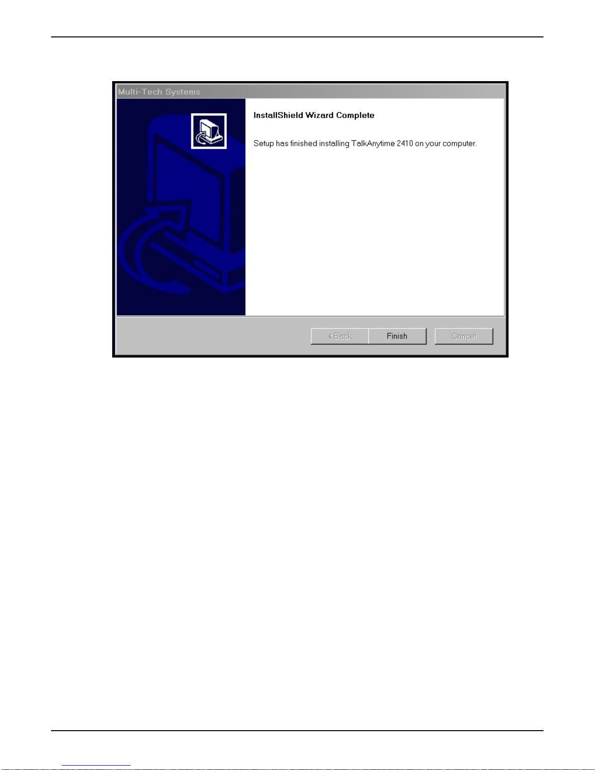
TalkAnytime User Guide Software Installation
8. When setup of the TalkAnytime software is complete, you will be prompted to run the TalkAnytime
software to configure the TalkAnytime unit.
Software installation is complete at this point. You may proceed with Technical Configuration now or
not, at your convenience.
Technical Configuration instructions are in the next chapter of this manual.
61
Page 62

Software Installation TalkAnytime® User Guide
Un-Installing the TalkAnytime Configuration Software
1. To un-install the TalkAnytime configuration software, go to Start | Programs and locate the entry for the
TalkAnytime program. Select Uninstall.
62
Page 63

TalkAnytime User Guide Software Installation
2. You will be asked to shut down other applications while uninstalling the TalkAnytime software.
3. Two confirmation screens will appear. Click Yes and OK when you are certain you want to continue
with the uninstallation process.
4. A special warning message similar to that shown below will appear concerning the TalkAnytime
software’s “.bin” file. Click Yes.
63
Page 64

Software Installation TalkAnytime® User Guide
5. A completion screen will appear.
Click Finish.
64
Page 65

Chapter 5: Technical Configuration
65
Page 66

Technical Configuration TalkAnytime User Guide
Configuring the TalkAnytime
When you begin using the TalkAnytime unit, you must
(A) decide which graphic user interface (GUI) to use (there is a Windows GUI and a web-based
GUI, and both can be accessed remotely),
(B) set values for two broad groups of configuration parameters on the TalkAnytime unit
(technical configuration parameters and phone book configuration parameters, both described
below), and
(C) complete the setup of the TalkAnytime unit for its inter-operation with a web server.
Two GUIs, both with Remote Access. The TalkAnytime unit has two GUIs.
One GUI is a Windows GUI, which can be accessed locally (by a connection between the “Console” port of
the TalkAnytime unit and a serial COM port of the command computer; if the command computer lacks a
serial port but has only USB2.0 ports instead, you will need a USB2.0-to-serial adapter). The Windows GUI
can be accessed remotely (through a phone line serving the TalkAnytime’s “Command Modem” port that
connects the command computer to the remote TalkAnytime unit through the unit’s built-in modem.
The second GUI, the web GUI, is built into the TalkAnytime unit. The TalkAnytime web GUI is accessible
to the command computer via the Internet or other IP network using a web browser.
If you intend to use the web GUI, you will still need first to use the Windows GUI to set an IP address for
the TalkAnytime unit. After an IP address has been established for the TalkAnytime unit, all subsequent
configuration can be done using the web GUI. Because of the obvious problem of conflicts, you cannot use
both GUIs at the same time.
Two Types of Configuration Parameters. There are two ways in which the TalkAnytime must be
configured before operation: technical configuration and phonebook configuration.
Technical Configuration. First, the TalkAnytime must be configured to operate with technical parameter
settings that will match the equipment with which it interfaces. There are six types of technical parameters
that must be set.
These technical parameters pertain to
(1) its operation in an IP network,
(2) its operation with telephony equipment,
(3) its transmission of digitized voice packets,
(4) certain telephony attributes that are common to particular nations or regions,
(5) its operation with a mail server on the same IP network (per SMTP parameters) such that log reports
about VoIP telephone call traffic can be sent to the administrator by email, and
(6) selecting the method by which log reports will be made accessible.
The process of specifying values for the various parameters in these six categories is what we call “technical
configuration” and it is described in this chapter.
Phonebook Configuration. The second type of configuration that is required for the TalkAnytime pertains
to the phone number dialing sequences that it will receive and transmit when handling calls. Dialing
patterns will be affected by the PBX/telephony equipment to which it is connected. We call this
“Phonebook Configuration,” and it is described in Chapter 6. The Quick Start Guide chapter of this manual
(Chapter 2) presents additional information on phonebook setup.
Website Implementation. The TalkAnytime unit must be on the same local network as your web server.
A link must be set up that will direct callers to the IP address of the TalkAnytime unit using a URL that
66
Page 67

TalkAnytime User Guide Technical Configuration
7
includes describes several attributes of the TalkAnytime service. That link will involve a graphics file that
will be used as an icon. The graphics file must be listed on the web page in a mouse-related command.
TalkAnytime also requires that several operating parameters be specified in a short Java script command
line. That Java script command line will also include a description of the characteristics required of the
user’s computer if TalkAnytime is to be used.
Website implementation is described later in this chapter.
Local Configuration
This manual primarily describes local configuration with the Windows GUI. After IP addresses have been
set locally using the Windows GUI, other configuration tasks, as well as operation and maintenance tasks
(see the Operation and Maintenance chapter of this manual), can be handled through either the web browser
GUI or the Windows GUI. Essentially, the Windows GUI and web-browser GUI differ only graphically,
not functionally.
Pre-Requisites
To complete the configuration of the
TalkAnytime unit, you must know
several things about the overall system.
Before configuring your TalkAnytime Gateway unit, you must know the values for several IP and
telephone parameters that describe the IP network system and telephony system (PBX or telco central office
equipment) with which the digital TalkAnytime will interact. If you plan to receive log reports on phone
traffic by email (SMTP), you must arrange to have an email address assigned to the TalkAnytime unit on
the email server on your IP network. A summary of this configuration information appears on page 26
(“Config Info CheckList”).
IP Parameters
The following parameters must be known about the network (LAN, WAN, Internet, etc.) to which the
TalkAnytime unit will connect:
Ask your computer network
administrator.
#
• IP Address
• IP Mask
• Gateway
• Domain Name Server (DNS) Info (optional)
• Determine whether or not 802.1p Packet Prioritization
will be used.
IP Network Parameters:
Record for this
TalkAnytime unit.
Write down the values for these IP parameters. You will need to enter these values in the “IP Parameters”
screen in the Configuration section of the TalkAnytime software.
6
Page 68

Technical Configuration TalkAnytime User Guide
T1 Telephony Parameters (for TA2410)
The following parameters must be known about the PBX or telco central office equipment to which the T1
TalkAnytime unit will connect:
T1 Phone Parameters
Ask phone company or
PBX maintainer.
#
• Which frame format is used?
• Which CAS or PRI protocol is used? ______________
• Clocking: Does the PBX or telco switch use
internal or external clocking? _________________
Note that the setting used in the TalkAnytime unit will
be the opposite of the setting used by the telco/PBX.
• Which line coding is used?
Write down the values for these T1 parameters. You will need to enter these values in the “T1/E1/ISDN
Parameters” screen in the Configuration section of the TalkAnytime software.
T1 Parameters:
Record for this
TalkAnytime unit.
Info needed to operate:
TA2410
ESF___ or D4___
AMI___ or B8ZS___
68
Page 69

TalkAnytime User Guide Technical Configuration
E1 Telephony Parameters (for TA3010)
The following parameters must be known about the PBX or telco central office equipment to which the E1
TalkAnytime unit will connect:
E1 Phone Parameters
Ask phone company or
PBX maintainer.
#
E1 Parameters:
Record for this
TalkAnytime unit.
Info needed to operate:
TA3010
• Which frame format is used?
MultiFrame w/ CRC4 modified_____
• Which CAS or PRI protocol is used? ______________
• Clocking: Does the PBX or telco switch use
internal or external clocking? _________________
Double Frame_____
MultiFrame w/ CRC4_____
Note that the setting used in the TalkAnytime unit will
be the opposite of the setting used by the telco/PBX.
• Which line coding is used?
• Pulse shape level?: (most commonly 0 to 40 meters)
AMI___ or HDB3___
Write down the values for these E1 parameters. You will need to enter these values in the “T1/E1/ISDN
Parameters” screen in the Configuration section of the TalkAnytime software.
SMTP Parameters (for email call log reporting)
required if log reports of
TA unit’s call traffic
are to be sent by email
SMTP Parameters
Preparation Task:
Ask Mail Server
administrator to set up
email account (with
password) for the
TalkAnytime unit itself.
Be sure to give a unique
identifier to each
individual TalkAnytime
unit. .
Get the IP address of the
mail server computer, as
well.
To: I .T. De par tmen t
re: email accoun t for VOIP
voip-unit2@biggytech.com
Optional
69
Page 70

Technical Configuration TalkAnytime User Guide
Config Info CheckList
Type of Config Info Gathered TalkAnytime
Configuration screen
on which to enter
Config Info
√
IP info for TalkAnytime unit
● IP address
● Gateway
● DNS IP (if used)
● 802.1p Prioritization (if used)
Frame Format
(Choices: ESF, D4, F4, SLC96)
Frame Format
(Choices: Double Frame, Multi-Frame w/
CRC4, Multi-Frame w/ CRC4 Modified)
CAS Protocol
(Choices: FXS Loop Start, E&M Wink,
E&M Wink w/ Dial Tone, FXO Ground
Start, FXO Loop Start, FXS Ground Start,
E&M Immediate, MFR2-China, Clear
Channel)
ISDN-PRI Protocol
(only if ISDN-PRI is used)
(Choices: Network, Terminal)
Clocking
(Choices: Internal, External)
Line Coding
(Choices: AMI, B8ZS)
Pulse Shape Level
(Choices: 0 – 40 m)
Country Code Regional Parameters
Email address for voip
(optional)
Reminder: Be sure to Save Setup after entering configuration values.
Ethernet/IP Parameters
T1/E1/ISDN Parameters
(TA2410 only)
T1/E1/ISDN Parameters
(TA3010 only)
T1/E1/ISDN Parameters
T1/E1/ISDN Parameters
T1/E1/ISDN Parameters
T1/E1/ISDN Parameters
T1/E1/ISDN Parameters
SMTP Parameters
70
Page 71

TalkAnytime User Guide Technical Configuration
Local Configuration Procedure (Summary)
After the TalkAnytime configuration software has been installed in the ‘Command’ PC (which is connected
to the TalkAnytime unit), several steps must be taken to configure the TalkAnytime unit to function in its
specific setting. Although the summary below includes all of these steps, some are optional.
1. Check Power and Cabling.
2. Start TalkAnytime Configuration Program.
3. Confirm Connection.
4. Solve Common Connection Problems.
A. Fixing a COM Port Problem.
B. Fixing a Cabling Problem.
5. Familiarize yourself with configuration parameter screens and how to access them.
6. Set Ethernet/IP Parameters.
7. Set up web browser GUI (optional).
8. Set Voice/Fax Parameters.
9. Set T1 or E1 Parameters.
10. Set ISDN Parameters (if ISDN-PRI is used instead of T1 or E1).
11. Set Regional Parameters (Phone Signaling Tones & Cadences and setup for built-in Remote
Configuration/Command Modem).
12. Set Custom Tones and Cadences (optional).
13. Set SMTP Parameters (applicable if Log Reports are via Email).
14. Set Log Reporting Method (GUI, locally in TalkAnytime Configuration program; or, SMTP, via email).
15. Set Baud Rate (of COM port connection to ‘Command’ PC).
16. View System Info screen and set updating interval (optional).
17. Save the TalkAnytime configuration.
18. Create a User Default Configuration (optional).
When technical configuration is complete, you will need to configure the TalkAnytime unit’s inbound
phonebook.
71
Page 72

Technical Configuration TalkAnytime User Guide
Local Configuration Procedure (Detailed)
You can begin the configuration process as a continuation of the TalkAnytime software installation. You
can establish your configuration or modify it at any time by launching the TalkAnytime program from the
Windows Start menu.
1. Check Power and Cabling. Be sure the TalkAnytime unit is turned on and connected to the computer
via the TalkAnytime unit’s Console Port (RJ45 connector is connected at the TalkAnytime unit; DB9
connector is connected at the computer’s COM port; if the computer has only USB2.0 ports and no serial
ports, use a USB2.0-to-serial adaptor).
2. Start TalkAnytime Configuration Program. Launch the TalkAnytime program from the Windows Start
menu (from the folder location determined during installation).
72
Page 73

TalkAnytime User Guide Technical Configuration
3. Confirm Connection. If the TalkAnytime unit is set for an available COM port and is correctly cabled to
the PC, the TalkAnytime main screen will appear. (If the main screen appears grayed out and seems
inaccessible, go to step 4.)
In the lower left corner of the screen, the connection status of the TalkAnytime will be displayed. The
messages in the lower left corner will change as detection occurs. The message “TalkAnytime Found”
confirms that the TalkAnytime unit is in contact with the TalkAnytime configuration program. Skip to
step 5.
73
Page 74

Technical Configuration TalkAnytime User Guide
4. Solving Common Connection Problems.
A. Fixing a COM Port Problem. If the TalkAnytime main screen appears but is grayed out and seems
inaccessible, the COM port that was specified for its communication with the PC is unavailable and must
be changed. An error message will appear.
To change the COM port setting, use the COM Port Setup dialog box, which is accessible via the
keyboard shortcut Ctrl + G or by going to the Connection pull-down menu and choosing “Settings.” In
the “Select Port” field, select a COM port that is available on the PC. (If no COM ports are currently
available, re-allocate COM port resources in the computer’s MS Windows operating system to make one
available. If your computer has USB2.0 ports but no serial COM ports, you will need a USB2.0-to-serial
adaptor.)
Ctrl + G
4B. Fixing a Cabling Problem. If the TalkAnytime unit cannot be located by the computer, three error
messages will appear (saying “TalkAnytime Not Found” and “Phone Database Not Read”).
In this case, the TalkAnytime unit is simply disconnected from the network. For instructions on
TalkAnytime cable connections, see the Cabling section of Chapter 3.
5. Configuration Parameter Groups: Getting Familiar, Learning About Access. The first part of
configuration concerns Ethernet/IP parameters, Voice/FAX parameters, T1/E1/ISDN parameters,
Regional parameters, SMTP parameters, and Logs. In the TalkAnytime software, these six types of
parameters are grouped together under “Configuration” and each has its own dialog box for entering
values. A seventh screen, the System Information screen, presents a summary of important information
about the voip but is read-only (that is, no parameters can be changed at this screen).
74
Page 75

TalkAnytime User Guide Technical Configuration
Generally, you can reach the dialog box for these parameter groups in one of four ways: pulldown menu,
toolbar icon, keyboard shortcut, or sidebar.
6. Set Ethernet/IP Parameters. This dialog box can be reached by pulldown menu, toolbar icon, keyboard
shortcut, or sidebar.
Accessing “Ethernet/IP Parameters”
Pulldown Icon
Shortcut Sidebar
Ctrl + Alt + I
In each field, enter the values that fit your particular network.
75
Page 76

Technical Configuration TalkAnytime User Guide
The Ethernet/IP Parameters fields are described in the tables and text passages below. Note that both
DiffServ parameters (Call Control PHB and VoIP Media PHB) must be set to zero if you enable Packet
Prioritization (802.1p). Nonzero DiffServ values negate the prioritization scheme.
Ethernet/IP Parameter Definitions
Field Name Values Description
Ethernet Parameters
Packet
Prioritization
(802.1p)
Frame Type Type II, SNAP
Y/N
Select to activate prioritization under 802.1p protocol (described
below).
.
Must be set to match network’s frame type. Default is
Type II.
802.1p
A draft standard of the IEEE about data traffic prioritization on Ethernet networks. The
802.1p draft is an extension of the 802.1D bridging standard. 802.1D determines how
prioritization will operate within a MAC-layer bridge for any kind of media. The
802.1Q draft for virtual local-area-networks (VLANs) addresses the issue of
prioritization for Ethernet networks in particular.
802.1p enacts this Quality-of-Service feature using 3 bits. This 3-bit code allows data
switches to reorder packets based on priority level. The descriptors for the 8 priority
levels are given below.
802.1p PRIORITY LEVELS
LOWEST PRIORITY
1 – Background: Bulk transfers and other activities permitted on the
network, but should not affect the use of network by other users
and applications.
Spare: An unused (spare) value of the user priority.
2 –
Best Effort (default): Normal priority for ordinary LAN traffic.
0 –
3 –
Excellent Effort: The best effort type of service that an information services
organization would deliver to its most important customers.
4 – Controlled Load: Important business applications subject to some
form of “Admission Control”, such as preplanning of Network
requirement, characterized by bandwidth reservation per flow.
Video: Traffic characterized by
5 –
delay < 100 ms.
Voice: Traffic characterized by
6 –
delay < 10 ms.
Network Control: Traffic urgently needed to maintain and support
7 -
network infrastructure.
HIGHEST PRIORITY
Call Control
Priority
VoIP Media
Priority
Others
(Priorities)
VLAN ID 1 - 4094 The 802.1Q IEEE standard allows virtual LANs to be defined
0-7, where 0 is
lowest priority
0-7, where 0 is
lowest priority
0-7, where 0 is
lowest priority
Sets the priority for signaling packets.
Sets the priority for media packets.
Sets the priority for SMTP, DNS, DHCP, and other packet types.
within a network. This field identifies each virtual LAN by
number.
76
Page 77

TalkAnytime User Guide Technical Configuration
7
Ethernet/IP Parameter Definitions (cont’d)
Field Name Values Description
IP Parameter fields
Gateway Name alphanumeric Descriptor of current voip unit to distinguish it from other
Enable DHCP Y/N
disabled by
default
IP Address 4-places, 0-255
IP Mask 4-places, 0-255
Gateway
DiffServ
Parameter
fields
4-places, 0-255.
DiffServ PHB (Per Hop Behavior) values pertain to a differential
prioritizing system for IP packets as handled by DiffServcompatible routers.
description. These descriptions are found in TCP/IP standards RFC2474,
RFC2597, and, for present purposes, in RFC3246, which describes the value
34 (34 decimal; 22 hex) for Assured Forwarding behavior (default for Call
Control PHB) and the value 46 (46 decimal; 2E hexadecimal) for Expedited
Forwarding behavior (default for Voip Media PHB). Before using values
other than these default values of 34 and 46, consult these standards
documents and/or a qualified IP telecommunications engineer.
units in system.
Dynamic Host Configuration Protocol is a method for
assigning IP address and other IP parameters to computers
on the IP network in a single message with great flexibility.
IP addresses can be static or temporary depending on the
needs of the computer.
The unique LAN IP address assigned to the
TalkAnytime unit.
Subnetwork address that allows for sharing of IP
addresses within a LAN.
The IP address of the device that connects your
TalkAnytime to the Internet.
There are 64 values, each with an elaborate technical
To disable DiffServ, configure both fields to 0 decimal.
The next page explains DiffServ in the context of the IP datagram.
Call Control PHB 0 – 63
default = 34
.
Voip Media PHB 0 – 63
default = 46
n
Value is used to prioritize call setup IP packets.
Value is used to prioritize the RTP/RTCP audio IP
packets.
7
Page 78

Technical Configuration TalkAnytime User Guide
The IP Datagram with Header, Its Type-of-Service field, & DiffServ
bits =>
0 4 8 16 19 24 31
VERS HLEN
IDENTIFICATION
TIME TO LIVE PROTOCOL HEADER CHECKSUM
TYPE OF
SERVICE
FLAGS
SOURCE IP ADDRESS
DESTINATION IP ADDRESS
IP OPTIONS (if any) PADDING …
DATA
…
TOTAL LENGTH
FRAGMENT OFFSET
end of header
The TOS field consists of eight bits, of which only the first six are used. These six bits are called the “Differentiated Service
Codepoint” or DSCP bits.
The Type of Service or “TOS” field
0 1 2 3 4 5 6 7
PRECEDENCE D T R
unused
The three ‘Precedence’ bits have eight values, 0-7, ranging from “normal” precedence (value of 0) to “network control”
(value of 7). When set, the D bit requests low delay, the T bit requests high throughput, and the R bit requests high
reliability.
Routers that support DiffServ can examine the six DSCP bits and prioritize the packet based on the DSCP value. The
DiffServ Parameters fields in the Ethernet/IP Parameters screen allow you to configure the DSCP bits to values supported by
the router. Specifically, the Voip Media PHB field relates to the prioritizing of audio packets (RTP and RTCP packets) and
the Call Control PHB field relates to the prioritzing of non-audio packets (packets concerning call set-up and tear-down,
gatekeeper registration, etc.).
The Call Control PHB parameter defaults to 34 decimal (22 hex; 100010 binary – consider vis-à-vis TOS field above) for
Assured Forwarding behavior. The Voip Media PHB parameter defaults to the value 46 decimal (2E hex; 101110 binary –
consider vis-à-vis TOS field above). To disable DiffServ, configure both fields to 0 decimal.
Ethernet/IP Parameter Definitions (cont’d)
Field Name Values Description
FTP Parameter fields
FTP Server
Enable
Y/N
Default = disabled
See “FTP Server
File Transfers” in
Operation &
Maintenance
chapter.
TalkAnytime unit has an FTP Server function
so that firmware and other important
operating software files can be transferred to
the unit via the network.
78
Page 79

TalkAnytime User Guide Technical Configuration
About Service Records
An SRV record holds the following information:
•
Service: the symbolic name of the desired service.
Protocol: this is usually either TCP or UDP.
•
Domain name: the domain for which this record is valid.
•
TTL: standard DNS time to live field.
•
Class: standard DNS class field (this is always IN).
•
Priority: the priority of the target host.
•
Weight: A relative weight for records with the same priority.
•
Port: the TCP or UDP port on which the service is to be found.
•
Target: the hostname of the machine providing the service.
•
An example SRV record might look like this:
_sip._tcp.example.com 86400 IN SRV 0 5 5060 sipserver.example.com.
This expression denotes a server named sipserver.example.com. This server listens on TCP port 5060 for SIP protocol
connections. The priority given here is 0, and the weight is 5.
7. Set up the Web Browser GUI (Optional). After an IP address for the TalkAnytime unit has been
established, you can choose to do any further configuration of the unit (a) by using the TalkAnytime web
browser GUI, or (b) by continuing to use the TalkAnytime Windows GUI. If you want to do configuration
work using the web browser GUI, you must first set it up. To do so, follow the steps below.
A. Set IP address of TalkAnytime unit using the TalkAnytime Configuration program (the Windows
GUI).
B. Save Setup in Windows GUI.
C. Close Windows GUI.
D. Install Java program from TalkAnytime product CD (on first use only).
E. Open web browser.
F. Browse to IP address of TalkAnytime unit.
G. If username and password have been established, enter them when when prompted.
H. Set browser to allow pop-ups at least for the IP address at which the TalkAnytime unit is located. The
TalkAnytime Web GUI makes extensive use of pop-up windows to access screens and commands.
I. Use web browser GUI to configure or operate TalkAnytime unit. The configuration screens in the web
browser GUI will have the same content as their counterparts in the Windows GUI; only the graphic
presentation will be different.
For more details on enabling the TalkAnytime web GUI, see the “Web Browser Interface” section of the
Operation & Maintenance chapter of this manual.
79
Page 80

Technical Configuration TalkAnytime User Guide
8. Set Voice/FAX Parameters. This dialog box can be reached by pulldown menu, toolbar icon, keyboard
shortcut, or sidebar.
Accessing “Voice/FAX Parameters”
Pulldown Icon
Shortcut Sidebar
Ctrl + H
80
Page 81

TalkAnytime User Guide Technical Configuration
In each field, enter the values that fit your particular network.
81
Page 82

Technical Configuration TalkAnytime User Guide
Note that Voice/FAX parameters are applied on a channel-by-channel basis. However, once you have
established a set of Voice/FAX parameters for a particular channel, you can apply this entire set of
Voice/FAX parameters to another channel by using the Copy Channel button and its dialog box. To copy
a set of Voice/FAX parameters to all channels, select “Copy to All” and click Copy.
82
Page 83

TalkAnytime User Guide Technical Configuration
The Voice/FAX Parameters fields are described in the tables below.
Voice/Fax Parameter Definitions
Field Name Values Description
Default --
When this button is clicked, all Voice/FAX parameters are set to their
default values.
Select
Channel
Copy
Channel
1-24 (2410)
1-30 (3010)
--
Channel to be configured is selected here.
Copies the Voice/FAX attributes of one channel to another channel.
Attributes can be copied to multiple channels or all channels at once.
Voice Gain -- Signal amplification (or attenuation) in dB.
Input Gain
+31dB
to
Modifies audio level entering voice channel before it is sent over the
network to the remote VOIP. The default & recommended value is 0 dB.
–31dB
Output Gain
+31dB
to
Modifies audio level being output to the device attached to the voice
channel. The default and recommended value is 0 dB.
–31dB
DTMF Parameters
DTMF Gain --
The DTMF Gain (Dual Tone Multi-Frequency) controls the volume level
of the DTMF tones sent out for Touch-Tone dialing.
DTMF Gain,
High Tones
+3dB to
-31dB &
Default value: -4 dB. Not to be changed except under supervision of
MultiTech’s Technical Support.
“mute”
DTMF Gain,
Low Tones
+3dB to
-31dB &
Default value: -7 dB. Not to be changed except under supervision of
MultiTech’s Technical Support.
“mute”
DTMF
In/Out of
Band
FAX/Modem Parameters
Out of
Band, or
Inband
When DTMF is set to Inband, the DTMF digits are passed through the
TalkAnytime unit as they are received. In MultiVOIP products, which are related
to the TalkAnytime unit, DTMF can also be set to Out of Band. In such cases, the
TalkAnytime unit detects DTMF tones at its input and regenerates them at its
output.
Not applicable to TalkAnytime.
83
Page 84

Technical Configuration TalkAnytime User Guide
Voice/Fax Parameter Definitions (cont’d)
Coder Parameters
Coder Manual or
Automatic
Determines whether selection of coder is manual or automatic.
When Automatic is selected, the local and remote voice channels
will negotiate the voice coder to be used by selecting the highest
bandwidth coder supported by both sides without exceeding the
Max Bandwidth setting. G.723, G.729, or G.711 are negotiated.
In general, this should be set to Automatic.
Selected
Coder
G.711 a/u
law 64
kbps;
G.726, @
16/24/32
/40 kbps;
G.727, @
nine bps
rates;
G.723.1 @
5.3 kbps,
6.3 kbps;
Select from a range of coders with specific bandwidths. The higher
the bps rate, the more bandwidth is used. The channel that you are
calling must have the same voice coder selected.
Default = G.723.1 @ 6.3 kbps, as required for H.323. Here 64K of
digital voice are compressed to 6.3K, allowing several simultaneous
conversations over the same bandwidth that would otherwise carry
only one.
To make selections from the Selected Coder drop-down list, the
Manual option must be enabled.
G.729,
8kbps;
Net Coder
@
6.4, 7.2, 8,
8.8, 9.6
kbps
Max
bandwidth
(coder)
11 – 128
kbps
Not applicable for TalkAnytime units.
Advanced
Features
Silence
Compression
Echo
Cancellation
Forward
--
Y/N Determines whether echo cancellation is enabled (checked) for this voice
Y/N Not applicable for TalkAnytime units.
Not applicable for TalkAnytime units.
channel.
Echo Cancellation removes echo and improves sound quality. Default =
on.
Error
Correction
84
Page 85

TalkAnytime User Guide Technical Configuration
Voice/Fax Parameter Definitions (cont’d) )
Field Name Values Description
Dynamic Jitter Buffer
Dynamic
Jitter Buffer
Dynamic Jitter defines a minimum and a maximum jitter value for
voice communications. When receiving voice packets from a
remote
source, varying delays between packets may occur due to
network traffic problems. This is called Jitter. To compensate, the
TalkAnytime unit uses a Dynamic Jitter Buffer. The Jitter Buffer
enables the TalkAnytime unit to wait for delayed voice packets by
automatically adjusting the length of the Jitter Buffer between
configurable minimum and maximum values. An Optimization
Factor adjustment controls how quickly the length of the Jitter
Buffer is increased when jitter increases on the network. The length
of the jitter buffer directly effects the voice delay on voip calls.
Minimum
Jitter Value
60 to 400
ms
The minimum dynamic jitter buffer of 60 milliseconds is the
minimum delay that would be acceptable over a low jitter network.
Default = 150 msec
Dynamic
Jitter
Maximum
Jitter Value
60 to 400
ms
The maximum dynamic jitter buffer of 400 milliseconds is the
maximum delay tolerable over a high jitter network.
Default = 300 msec
Optimization Factor
0 to 12 The Optimization Factor determines how quickly the length of the
Dynamic Jitter Buffer is changed based on actual jitter encountered
on the network. Selecting the minimum value of 0 means low voice
delay is desired, but increases the possibility of jitter-induced voice
quality problems. Selecting the maximum value of 12 means
highest voice quality under jitter conditions is desired at the cost of
increased voice delay.
Default = 7.
85
Page 86

Technical Configuration TalkAnytime User Guide
Voice/Fax Parameter Definitions (cont’d) )
Field Name Values Description
Auto Disconnect
Automatic
-- The Automatic Disconnection group provides four options which
Disconnection
Jitter Value 1-65535
milliseconds
Call
Duration
Consecutive
1-65535
seconds
1-65535 Consecutive Packets Lost defines the number of consecutive
Packets Lost
Network
Disconnection
1 to 65535
seconds;
Default =
30 sec.
can be used singly or in any combination.
The Jitter Value defines the average inter-arrival packet deviation
(in milliseconds) before the call is automatically disconnected. The
default is 300 milliseconds. A higher value means voice
transmission will be more accepting of jitter. A lower value is less
tolerant of jitter.
Inactive by default. When active, default = 300 ms. However, value
must equal or exceed Dynamic Minimum Jitter Value.
Call Duration defines the maximum length of time (in seconds)
that a call remains connected before the call is automatically
disconnected.
Inactive by default.
When active, default = 180 sec.
This may be too short for most configurations, requiring upward
adjustment.
packets that are lost after which the call is automatically
disconnected.
Inactive by default.
When active, default = 30
Specifies how long to wait before disconnecting the call when IP
network connectivity with the remote site has been lost.
86
Page 87

TalkAnytime User Guide Technical Configuration
7
9. Set T1/E1/ISDN Parameters. This dialog box can be reached by pulldown menu, keyboard shortcut, or
sidebar.
Accessing “T1/E1/ISDN Parameters”
Pulldown Icon
--
Shortcut Sidebar
Ctrl + T
8
Page 88

Technical Configuration TalkAnytime User Guide
In each field, enter the values that fit your particular network.
88
Page 89

TalkAnytime User Guide Technical Configuration
T1 Parameters. The parameters applicable to T1 and their values are shown in the figure below. These T1
Parameter fields are described in the tables that follow.
89
Page 90

Technical Configuration TalkAnytime User Guide
T1 Parameter Definitions
Field Name Values Description
T1/E1/ISDN T1 North American digital telephony standard.
Long-Haul
Mode
CRC Check
(Cyclic
Redundancy
Check)
Frame Format F4, D4, ESF,
CAS Protocol E&M Immed Strt
Y/N In Long-Haul Mode, the TalkAnytime automatically recovers
received signals as low as –36 dB. The maximum reachable length
with 22 AWG cable is 2000 meters. When Long-Haul Mode is
disabled, signals as low as –10 dB can be received.
Default: disabled.
Y/N When enabled, allows generation and checking of CRC bits. If not
enabled, all check bits in the transmit direction are set. Only applies
to ESF frame format.
Default: enabled.
Frame Format of TalkAnytime should match that used by PBX or
SLC96
E&M Wink Start
E&M Wink with
dial tone
FXO Ground Strt
FXO Loop Start
FXS Ground Strt
FXS Loop Start
telco. ESF and D4 are commonly used.
Channel Associated Signaling (CAS) is a method of incorporating
telephony signaling info into a T1 voice/data stream. In CAS, the
signaling bits (the A, B, C, and D bits) are multiplexed into the
signal stream of each T1 channel. (By contrast, in Common Channel
Signaling (CCS), one channel handles signaling for all other
channels.) Each CAS protocol defines the states of the signaling bits
during the various stages of a call (IDLE, SEIZED, ANSWER, RINGON, RING-OFF).
The CAS protocol code allows the TalkAnytime to interact properly
with the PBX or central-office switch that it serves.
Match this parameter to the setting of PBX or central-office switch.
FXS Options –
No Response
Timer
1 – 65535
(in seconds)
Length of time before call connection attempt is abandoned.
Applicable only when an FXS CAS protocol is selected.
90
Page 91

TalkAnytime User Guide Technical Configuration
For TalkAnytime units, supervision of CAS protocols is supported only forFXS Ground Start and FXS Loop Start.
The parameters described in the following table for FXS Ground Start also apply to FXS Loop Start.
T1 Parameter Definitions
Field Name Values Description
FXS Ground/Loop Start
Supervision Parameters
Answer Delay
(Enable)
Answer Delay
Timer
Y/N When this option is selected, the FXS interface sends the
numeric
(in seconds)
connection notice to the calling party only when the
Answer Delay Timer expires. The connection notice is
sent regardless of whether or not the called extension has
gone offhook.
When Answer Delay is enabled, this value determines
when the FXS interface sends the connection notice.
91
Page 92

Technical Configuration TalkAnytime User Guide
T1 Parameter Definitions (cont’d)
Field Name Values Description
FXS Ground/Loop Start
Supervision Parameters
Tone Detection
Y/N After a specified tone (chosen from the Available Tones
(Enable)
Available
Tones (List)
Answer Tones
(List)
Busy Tone, Dial
Tone, Reorder Tone
Survivability Dial
Tone, Unobtainable
Tone
Busy Tone, Dial
Tone, Reorder Tone
Survivability Dial
Tone, Unobtainable
Tone
list) coming from the PBX is stopped, the FXS interface
will send the ‘connect’ signal to the calling party.
List from which tones can be chosen to signal call
answer.
Currently chosen call-answer supervision tone.
ISDN Parameters
Field Name Values Description
Enable
ISDN-PRI
Terminal/
Network
Y/N If digital connection is ISDN-PRI type, this box should be
checked. When ISDN is enabled, the “CAS Protocols”
field is grayed out (ISDN has its own signaling method).
either
“Terminal” or
“Network”
When “Terminal” is selected, it indicates that the TalkAnytime
unit should emulate the subscriber (terminal) side of the digital
connection. When “Network” is selected, it indicates that the
TalkAnytime unit should emulate the central office (network)
side of the digital connection.
Setting used for TalkAnytime unit must be opposite to the
setting used in the PBX. For example, if the PBX is set to
“Terminal,” then the TalkAnytime unit must be set to
“Network.”
92
Page 93

TalkAnytime User Guide Technical Configuration
T1 Parameter Definitions (cont’d)
Field Name Values Description
ISDN Parameters
Country see table, later
this chapter
Operator see table, later
this chapter
Note on
Country &
Operator
options.
Numbering Details Parameters
Calling Party
Number Type
Called Party
Number Type
Called Party
Number Plan
__ [ISDN implementation options
unknown,
national,
international,
network specific,
subscriber,
abbreviated,
as received from
network
unknown,
national,
international,
network specific,
subscriber,
abbreviated,
as received from
network
unknown,
ISDN telephony,
data,
telex,
national standard,
private,
as received from
network
Country in which TalkAnytime
is operating with ISDN.
Indicates phone switch
manufacturer/model or refers
to telco so as to specify the
switching system in question.
ISDN is implemented
somewhat differently in
different switches.
are shown, arranged by
country, in a table below – soon
after E1 Parameter Definitions.]
Calling party type is part of
calling party Number
Information element that is sent
on ISDN line. The Calling party
number information element
identifies the origin of a call.
Called Party Number Type and
Called Party Number Plan are
part of Calling Party Number
Information element that is sent
on ISDN line. The Called party
number information element
identifies destination of a call.
The call dialing plan under
which the called party operates.
93
Page 94

Technical Configuration TalkAnytime User Guide
T1 Parameter Definitions (cont’d)
Field Name Values Description
General T1/E1/ISDN Parameters
Line Build Out 0 dB, -7.5 dB,
-15 dB, -22.5 dB
Pulse Shape
Level
0 to 40 Meters
40 to 81 m
81 to 122 m
122 to 162 m
162 to 200 m
Caller ID Parameters Not applicable to TalkAnytime.
Caller ID
Y/N Turns Caller ID feature on (if checked) and off (if
Enable
Calling
0-9, *, #
Number Prefix
(Caller ID)
Calling
0-9, *, # A DTMF symbol used to mark the end of the calling party
Number Suffix
(Caller ID)
Flash Hook Parameters Not applicable to TalkAnytime.
Detect Flash
Y/N This setting determines whether or not the MultiVOIP
Hook
To reduce the crosstalk on received signals, a transmit
attenuator can be placed in the data path. Transmit
attenuation is selectable. Default: O dB
Refers to length of cable between TalkAnytime and
PBX/telco in meters. Most common will be 0 to 40m.
unchecked).
A DTMF symbol used to mark the beginning of the calling party
number for use with Caller ID. Maximum length: 4 characters.
number for use with Caller ID.
responds to hook-flash signals.
Maximum length: 4 characters.
Detection Time 100 – 1500
milliseconds
Generation
Time
100 – 1500
milliseconds
Minimum hook-flash time that will be interpreted as a valid
flash by the MultiVOIP.
In some systems, a MultiVOIP might receive a hook-flash signal
from an upstream device (a PBX, voip or other device) and must
replicate it to a downstream device. This parameter determines the
duration of the hook-flash signal that is passed to a downstream
device.
Clocking External/Internal Set opposite to telco/PBX setting. Example: if telco clocking
internal, set VOIP clocking as external.
94
Page 95

TalkAnytime User Guide Technical Configuration
T1 Parameter Definitions (cont’d)
Field Name Values Description
Line Coding AMI / B8ZS Match to PBX or telco.
PCM Law A-Law/Mu-Law Match to PBX or telco. “
Mu-law” is analog-to-digital
compression/expansion
standard used in North
America. “A-law” is European
standard.
Yellow Alarm
Format
Bit 2 / 1111… Depending on the Frame
Format used, there are choices
of Yellow Alarm format, as
follows:
D4: -Bit2 = 0 in every speech
channel
-FS bit of frame 12 is forced
to one.
ESF: -Bit2 = 0 in every speech
channel
–1111111100000000 pattern
in data link channel.
Check with your PBX/telco
administrator for the correct
setting or use the default value
(1111 … ).
95
Page 96

Technical Configuration TalkAnytime User Guide
E1 Parameters. The parameters applicable to E1 and their values are shown in the figure below. These E1
Parameter fields are described in the tables that follow.
96
Page 97

TalkAnytime User Guide Technical Configuration
7
E1 Parameter Definitions
Field Name Values Description
T1/E1/ISDN E1 European standard.
Long-Haul
Mode
CRC Check
(Cyclic
Redundancy
Check)
Frame Format Double Frame;
CAS Protocol E&M Immed Strt
Y/N In Long-Haul Mode, the TalkAnytime automatically
recovers received signals as low as –36 dB. The maximum
reachable length with 22 AWG cable is 2000 meters. When
Long-Haul Mode is disabled, signals as low as –10 dB can
be received.
Default: disabled.
-- Not applicable to E1.
Frame Format of TalkAnytime should match that used by
MultiFrame
(with CRC4);
MultiFrame
(w/CRC4,
modified)
E&M Wink Start
E&M Wink with
dial tone
FXO Ground Strt
FXO Loop Start
FXS Ground Strt
FXS Loop Start
MFR2ITU
MFR2 China
MFR2 ANI
PBX or telco.
Channel Associated Signaling (CAS) is a method of
incorporating telephony signaling info into an E1
voice/data stream. In CAS, the signaling bits (the A, B, C,
and D bits) are multiplexed into the signal stream of each
E1 channel. (By contrast, in Common Channel Signaling
(CCS), one channel handles signaling for all other
channels.) Each CAS protocol defines the states of the
signaling bits during the various stages of a call (IDLE,
SEIZED, ANSWER, RING-ON, RING-OFF).
The CAS protocol code allows the VOIP to interact
properly with the PBX or central-office switch that it
serves. The need to download CAS protocols arises for
only a small minority of VOIP users, and only when
PBX/switch is found to be incompatible with standard
protocols.
FXS Options –
No Response
Timer
1 – 65535
(in seconds)
Match this parameter to the setting of PBX or central-office
switch.
Length of time before call connection attempt is
abandoned. Applicable only when FXS Loop Start or FXS
Ground Start is selected as the CAS protocol.
9
Page 98

Technical Configuration TalkAnytime User Guide
The values in the table below apply to both the FXS Ground Start CAS protocol and the FXS Loop Start CAS protocol.
E1 Parameter Definitions
Field Name Values Description
FXS Ground/Loop Start
Supervision Parameters
Answer Delay
(Enable)
Answer Delay
Timer
Y/N When this option is selected, the
numeric
(in seconds)
FXS interface sends the
connection notice to the calling
party only when the Answer
Delay Timer expires. The
connection notice is sent
regardless of whether or not the
called extension has gone
offhook.
When Answer Delay is enabled,
this value determines when the
FXS interface sends the
connection notice.
98
Page 99

TalkAnytime User Guide Technical Configuration
E1 Parameter Definitions (cont’d)
Field Name Values Description
FXS Ground/Loop Start
Supervision Parameters
Tone Detection
Y/N After a specified tone (chosen
(Enable)
Available
Tones (List)
Answer Tones
(List)
Busy Tone, Dial
Tone, Reorder Tone
Survivability Dial
Tone, Unobtainable
Tone
Busy Tone, Dial
Tone, Reorder Tone
Survivability Dial
Tone, Unobtainable
Tone
from the Available Tones list)
coming from the PBX is
stopped, the FXS interface will
send the ‘connect’ signal to the
calling party.
List from which tones can be
chosen to signal call answer.
Currently chosen call-answer
supervision tone.
ISDN Parameters
Field Name Values Description
Enable
ISDN-PRI
Terminal/
Network
Y/N If digital connection is ISDN-
PRI type, this box should be
checked. When ISDN is
enabled, the “CAS Protocols”
field is grayed out (ISDN has its
own signaling method).
either
“Terminal” or
“Network”
When “Terminal” is selected, it
indicates that the TalkAnytime
should emulate the subscriber
(terminal) side of the digital
connection. When “Network”
is selected, it indicates that the
TalkAnytime should emulate
the central office (network) side
of the digital connection.
Setting used for TalkAnytime must
be opposite to the setting used in
the PBX. For example, if the PBX is
set to “Terminal,” then the
TalkAnytime must be set to
“Network.”
99
Page 100

Technical Configuration TalkAnytime User Guide
E1 Parameter Definitions (cont’d)
Field Name Values Description
ISDN Parameters
Country see table, later
this chapter
Operator see table, later
this chapter
Note on
Country &
Operator
options.
Numbering Details Parameters
Calling Party
Number Type
Called Party
Number Type
Called Party
Number Plan
__ [ISDN implementation options
unknown,
national,
international,
network specific,
subscriber,
abbreviated,
as received from
network
unknown,
national,
international,
network specific,
subscriber,
abbreviated,
as received from
network
unknown,
ISDN telephony,
data,
telex,
national standard,
private,
as received from
network
Country in which TalkAnytime
is operating with ISDN.
Indicates phone switch
manufacturer/model or refers
to telco so as to specify the
switching system in question.
ISDN is implemented
somewhat differently in
different switches.
are shown, arranged by
country, in a table below – soon
after E1 Parameter Definitions.]
Calling party type is part of
calling party Number
Information element that is sent
on ISDN line. The Calling party
number information element
identifies the origin of a call.
Called Party Number Type and
Called Party Number Plan are
part of Calling Party Number
Information element that is sent
on ISDN line. The Called party
number information element
identifies destination of a call.
The call dialing plan under
which the called party operates.
100
 Loading...