

Page 1
®
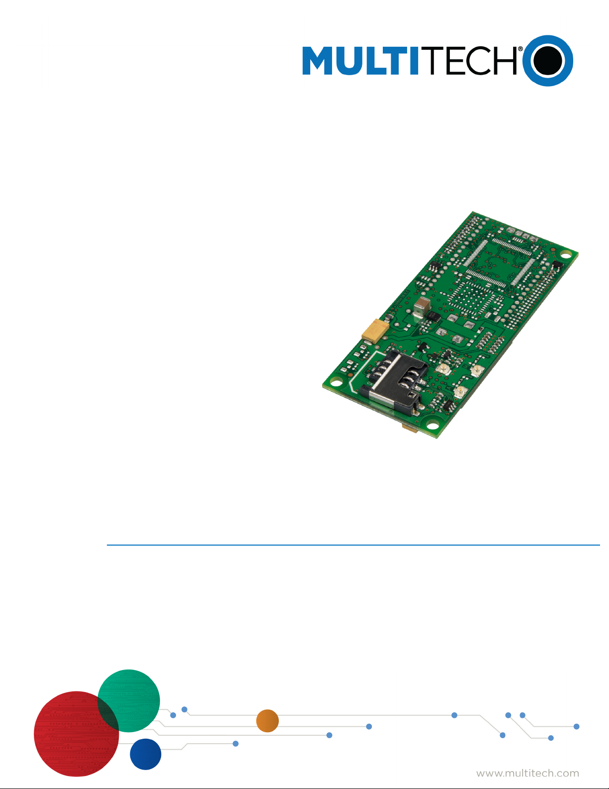
SocketModem
MTSMC-LSP3 Device Guide
Cell
Page 2
SOCKETMODEM® CELL DEVICE GUIDE
SocketModem®Cell Device Guide
Models: MTSMC-LSP3, MTSMC-LSP3-U
Part Number: S000703, Version 1.2
Copyright
This publication may not be reproduced, in whole or in part, without the specific and express prior written permission signed by an executive officer of
Multi-Tech Systems, Inc. All rights reserved. Copyright © 2019 by Multi-Tech Systems, Inc.
Multi-Tech Systems, Inc. makes no representations or warranties, whether express, implied or by estoppels, with respect to the content, information,
material and recommendations herein and specifically disclaims any implied warranties of merchantability, fitness for any particular purpose and noninfringement.
Multi-Tech Systems, Inc. reserves the right to revise this publication and to make changes from time to time in the content hereof without obligation of
Multi-Tech Systems, Inc. to notify any person or organization of such revisions or changes.
Trademarks and Registered Trademarks
Multi-Tech, and the Multi-Tech logo, and SocketModem are trademarks and registered trademarks of Multi-Tech Systems, Inc. All other products and
technologies are the trademarks or registered trademarks of their respective holders.
Legal Notices
The MultiTech products are not designed, manufactured or intended for use, and should not be used, or sold or re-sold for use, in connection with
applications requiring fail-safe performance or in applications where the failure of the products would reasonably be expected to result in personal injury or
death, significant property damage, or serious physical or environmental damage. Examples of such use include life support machines or other life
preserving medical devices or systems, air traffic control or aircraft navigation or communications systems, control equipment for nuclear facilities, or
missile, nuclear, biological or chemical weapons or other military applications (“Restricted Applications”). Use of the products in such Restricted
Applications is at the user’s sole risk and liability.
MULTITECH DOES NOT WARRANT THAT THE TRANSMISSION OF DATA BY A PRODUCT OVER A CELLULAR COMMUNICATIONS NETWORK WILL BE
UNINTERRUPTED, TIMELY, SECURE OR ERROR FREE, NOR DOES MULTITECH WARRANT ANY CONNECTION OR ACCESSIBILITY TO ANY CELLULAR
COMMUNICATIONS NETWORK. MULTITECH WILL HAVE NO LIABILITY FOR ANY LOSSES, DAMAGES, OBLIGATIONS, PENALTIES, DEFICIENCIES, LIABILITIES,
COSTS OR EXPENSES (INCLUDING WITHOUT LIMITATION REASONABLE ATTORNEYS FEES) RELATED TO TEMPORARY INABILITY TO ACCESS A CELLULAR
COMMUNICATIONS NETWORK USING THE PRODUCTS.
The MultiTech products and the final application of the MultiTech products should be thoroughly tested to ensure the functionality of the MultiTech
products as used in the final application. The designer, manufacturer and reseller has the sole responsibility of ensuring that any end user product into
which the MultiTech product is integrated operates as intended and meets its requirements or the requirements of its direct or indirect customers.
MultiTech has no responsibility whatsoever for the integration, configuration, testing, validation, verification, installation, upgrade, support or maintenance
of such end user product, or for any liabilities, damages, costs or expenses associated therewith, except to the extent agreed upon in a signed written
document. To the extent MultiTech provides any comments or suggested changes related to the application of its products, such comments or suggested
changes is performed only as a courtesy and without any representation or warranty whatsoever.
Contacting MultiTech
Knowledge Base
The Knowledge Base provides immediate access to support information and resolutions for all MultiTech products. Visit http://www.multitech.com/kb.go.
Support Portal
To create an account and submit a support case directly to our technical support team, visit: https://support.multitech.com.
Support
Business Hours: M-F, 8am to 5pm CT
Country By Email By Phone
Warranty
To read the warranty statement for your product, visit https://www.multitech.com/legal/warranty. For other warranty options, visit
www.multitech.com/es.go.
World Headquarters
Multi-Tech Systems, Inc.
2205 Woodale Drive, Mounds View, MN 55112
Phone: (800) 328-9717 or (763) 785-3500
Fax (763) 785-9874
2 SocketModem®Cell MTSMC-LSP3 Device Guide
Page 3

CONTENTS
Contents
Chapter 1 – Product Overview ................................................................................................................................. 6
Product Overview.......................................................................................................................................................... 6
Documentation ............................................................................................................................................................. 6
Product Build Options ................................................................................................................................................... 7
Chapter 2 – Mechanical Drawings............................................................................................................................ 8
MTSMC-LSP3 ................................................................................................................................................................. 8
MTSMC-LSP3-U ............................................................................................................................................................. 9
Chapter 3 – Specifications...................................................................................................................................... 10
MTSMC-LSP3 and MTSMC-LSP3-U Specifications....................................................................................................... 10
Powering Down Your Device ...................................................................................................................................... 11
UART DC Electrical Characteristics.............................................................................................................................. 11
Absolute Maximum Rating........................................................................................................................................ 12
Electrical Characteristics Other Pins ........................................................................................................................... 12
Pinout Specifications................................................................................................................................................... 12
Pin Availability by Build............................................................................................................................................... 13
Power Measurements................................................................................................................................................. 14
MTSMC-LSP3 Power Draw ........................................................................................................................................ 14
MTSMC-LSP3-U Power Draw .................................................................................................................................... 15
Mounting Hardware.................................................................................................................................................... 15
Recommended Parts................................................................................................................................................. 15
Chapter 4 – Antennas ............................................................................................................................................ 16
Antenna System Cellular Devices................................................................................................................................ 16
Requirements for Cellular Antennas with regard to FCC/IC Compliance ................................................................. 16
LTE Antenna ............................................................................................................................................................... 16
LTE Antenna Diversity ................................................................................................................................................. 16
Selecting Antennas ................................................................................................................................................... 17
Placing External Antennas ........................................................................................................................................ 17
Placing GPS Antennas .............................................................................................................................................. 17
Antenna Approvals and Safety Considerations ........................................................................................................ 17
Diversity and Power Draw ....................................................................................................................................... 17
OEM Integration ......................................................................................................................................................... 17
FCC & IC Information to Consumers ......................................................................................................................... 17
FCC Grant Notes........................................................................................................................................................ 17
Host Labeling............................................................................................................................................................. 18
Chapter 5 – Safety Information .............................................................................................................................. 19
Handling Precautions .................................................................................................................................................. 19
Radio Frequency (RF) Safety ....................................................................................................................................... 19
SocketModem®Cell MTSMC-LSP3 Device Guide 3
Page 4

CONTENTS
Sécurité relative aux appareils à radiofréquence (RF).............................................................................................. 19
Interference with Pacemakers and Other Medical Devices ...................................................................................... 20
Potential interference ............................................................................................................................................... 20
Precautions for pacemaker wearers ........................................................................................................................ 20
Vehicle Safety.............................................................................................................................................................. 20
Device Maintenance ................................................................................................................................................... 20
User Responsibility...................................................................................................................................................... 21
Chapter 6 – Regulatory Information....................................................................................................................... 22
47 CFR Part 15 Regulation Class B Devices ................................................................................................................. 22
FCC Grant Information ................................................................................................................................................ 23
FCC Part 15................................................................................................................................................................ 23
Chapter 7 – Environmental Notices........................................................................................................................ 25
Waste Electrical and Electronic Equipment Statement .............................................................................................. 25
WEEE Directive.......................................................................................................................................................... 25
Instructions for Disposal of WEEE by Users in the European Union ........................................................................ 25
REACH Statement ....................................................................................................................................................... 25
Registration of Substances........................................................................................................................................ 25
Restriction of the Use of Hazardous Substances (RoHS) ............................................................................................ 25
Chapter 8 – Sprint Activation and OMA-DM Commands (LSP3).............................................................................. 27
Chapter 9 – Labels.................................................................................................................................................. 28
Approvals and Certifications ....................................................................................................................................... 28
Example Labels............................................................................................................................................................ 28
Chapter 10 – Using Connection Manager ............................................................................................................... 30
Installing Connection Manager ................................................................................................................................... 30
Setting Up a Serial Device in Windows Device Manager............................................................................................ 31
Connecting a Device.................................................................................................................................................... 33
Uninstalling Connection Manager............................................................................................................................... 34
Connection Manager User Interface........................................................................................................................... 34
Main tab.................................................................................................................................................................... 35
Settings tab ............................................................................................................................................................... 36
Connection tab.......................................................................................................................................................... 36
Details tab ................................................................................................................................................................. 36
Terminal tab.............................................................................................................................................................. 36
Charts tab.................................................................................................................................................................. 36
Troubleshooting.......................................................................................................................................................... 36
Serial COM port is not available in the Serial Modem Settings................................................................................ 36
Device is not detected ("No Device") ....................................................................................................................... 36
MultiConnect Cell USB Modem is not detected ....................................................................................................... 37
Connection Manager is not working, and a device connected to the computer is not detected............................ 37
Connection Manager displays "Device Error" status for a serial device .................................................................. 37
4 SocketModem®Cell MTSMC-LSP3 Device Guide
Page 5

CONTENTS
Index...................................................................................................................................................................... 38
SocketModem®Cell MTSMC-LSP3 Device Guide 5
Page 6

PRODUCT OVERVIEW
Chapter 1 – Product Overview
Product Overview
SocketModem Cell models are complete, ready-to-integrate communications devices that offer standards-based
LTE performance. These quick-to-market communications devices allow developers to add wireless communication
to products with a minimum of development time and expense. SocketModem Cell models are based on industrystandard open interfaces and use MultiTech’s Universal Socket design.
Documentation
The following documentation is available at multitech.com/support.
Document Description Part Number
SocketModem Cell LTE CAT1
MTSMC-LSP3 Device Guide
Universal Developer Kit 2.0
Developer Guide
USB Driver Installation Guide Instructions for installing USB drivers on Linux and Windows
Telit LE920x4/LE910Cx Series
AT Commands Reference
Guide
This document. Provides overview, safety and regulatory
information, design considerations, schematics, and device
information.
Information for developing with the MTUDK2 Developer Kit.
Includes an overview, design considerations, schematics, and
installation and operation information.
Systems.
Lists AT Commands and parameters used to configure your
device.
S000703
S000610
S000616
80490ST10778A
Rev. 4
6 SocketModem®Cell MTSMC-LSP3 Device Guide
Page 7
Product Build Options
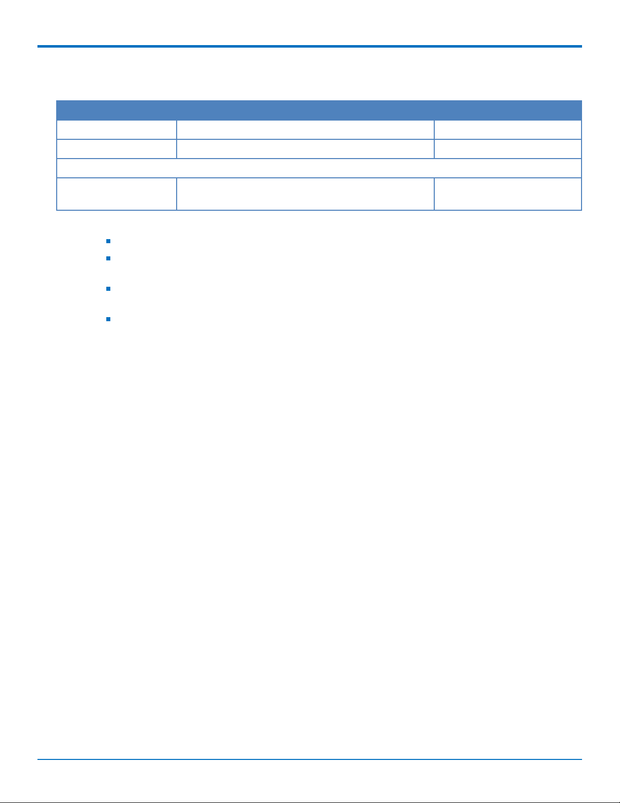
Product Description Carrier/Region
MTSMC-LSP3 Embedded LTE Cat 1 serial modem with GNSS Sprint
MTSMC-LSP3-U Embedded LTE Cat 1 USB modem with GNSS Sprint
Developer Kits
PRODUCT OVERVIEW
MTUDK2-ST-Cell Developer Kit for SocketModem, and Dragonfly cellular
devices.
Note:
These units ship without network activation.
To connect them to the cellular network, you need a cellular account. For more information, refer to
Account Activation.
The complete product code may end in .Rx. For example, MTSMC-LSP3.Rx, where R is revision and x
is the revision number.
All builds can be ordered individually or in 50-packs. Add SP to the model number for a single pack.
All
SocketModem®Cell MTSMC-LSP3 Device Guide 7
Page 8
MECHANICAL DRAWINGS
Chapter 2 – Mechanical Drawings
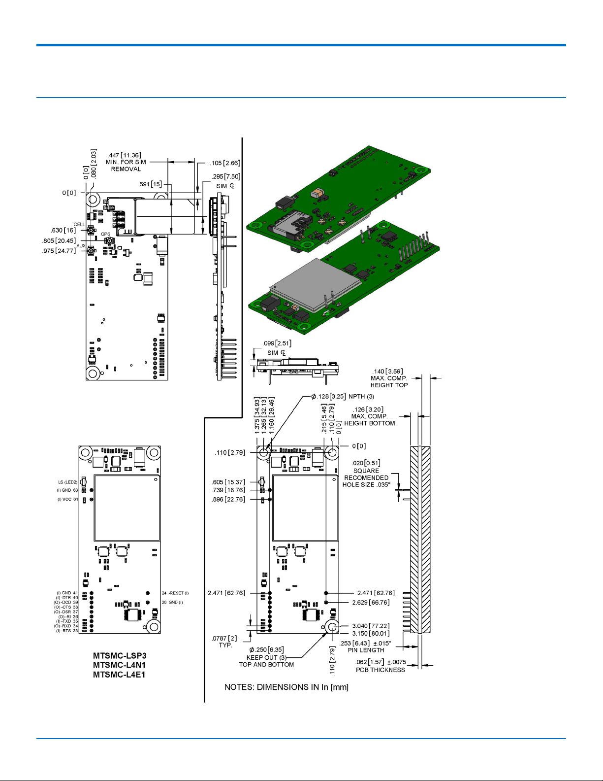
MTSMC-LSP3
8 SocketModem®Cell MTSMC-LSP3 Device Guide
Page 9
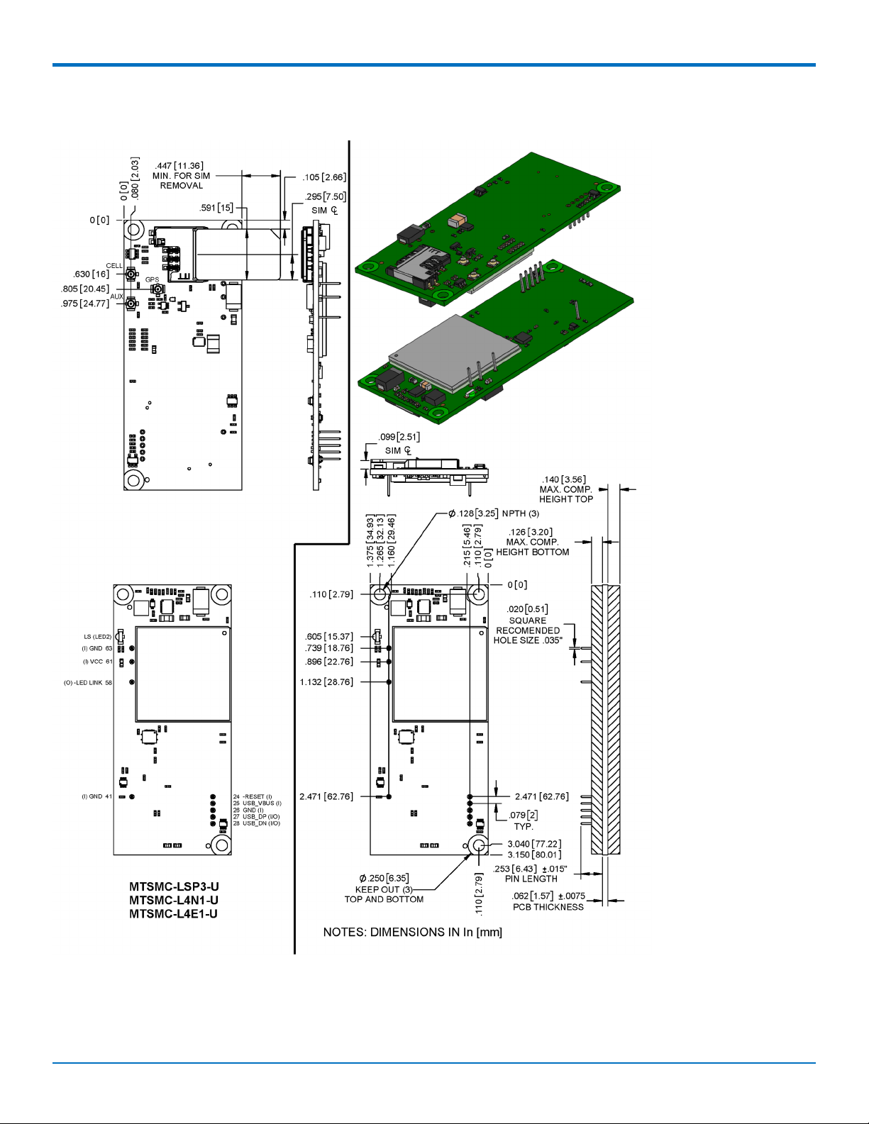
MTSMC-LSP3-U
MECHANICAL DRAWINGS
SocketModem®Cell MTSMC-LSP3 Device Guide 9
Page 10

SPECIFICATIONS
Chapter 3 – Specifications
MTSMC-LSP3 and MTSMC-LSP3-U Specifications
Category Description
General
Standards LTE FDD Cat 1, 3GPP release 10 compliant
USB Interface is CDC-ACM compliant
TCP/IP Functions FTP, TCP, UDP, SMTP stack, IPv4/IPv6 stack
Frequency Bands 4G: 1900 (B2/B25) / AWS 1700 (B4) / 850 (B5/B26) / B12 (700)
Speed
Data Speed LTE: 10 Mbps downlink/ 5 Mbps uplink
Interface
USB Interface USB 2.0 HS/HSIC
Serial Modem Interface Up to 921.6 Kbps
Physical Description
Weight 0.4 oz. (10 g)
Dimensions Refer to Mechanical Drawing for Dimensions.
Connectors
Antenna Connector 2 surface mount UFL connectors for cellular, Rx diversity/MIMO
SIM 1.8V and 3V SIM holder for mini-SIM card
Environment
Operating Temperature -40° C to +85° C
Humidity 20%-90% RH, non-condensing
Power Requirements
Input Voltage 3.3-5 VDC
SMS
SMS Point-to-Point messaging
Mobile-Terminated SMS
Mobile-Originated SMS
10 SocketModem®Cell MTSMC-LSP3 Device Guide
Page 11
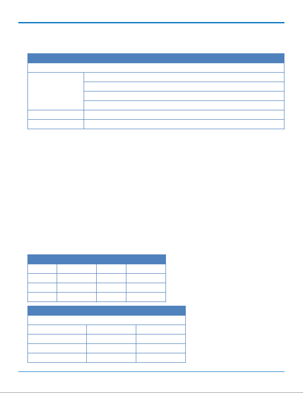
Category Description
Certifications and Compliance
SPECIFICATIONS
EMC and Radio
Compliance
Safety Compliance UL 60950-1 2nd ED
Carrier Sprint
FCC Part 15 Class B
FCC Part 22
FCC Part 24
FCC Part 27
Powering Down Your Device
CAUTION: Failing to properly power down the device before removing power may corrupt your device's file
system.
To properly power down your device, use the following sequence or pull 3G_ONOFF signal low:
1. Issue the AT#SHDN command.
2. Wait 30 seconds.
3. Power off or disconnect power.
Note: If you send AT#SHDN and do not remove power AND the 3G_ONOFF line is high, the radio restarts after
60 seconds.
UART DC Electrical Characteristics
Units: Volts
Applies to the following pins:
Pin Signal Name Pin Signal Name
J33 -RTS J37 -DSR
J34 -RXD J38 -CTS
J35 -TXD J39 -DCD
J36 -RI J40 -DTR
Parameter Minimum Maximum
3.3 Volt Powered
Input Low Level 0 0.55
Input High Level 1.5 3.3
Output Low Level 0 0.55
Output High Level 2.35 3.3
SocketModem®Cell MTSMC-LSP3 Device Guide 11
Page 12
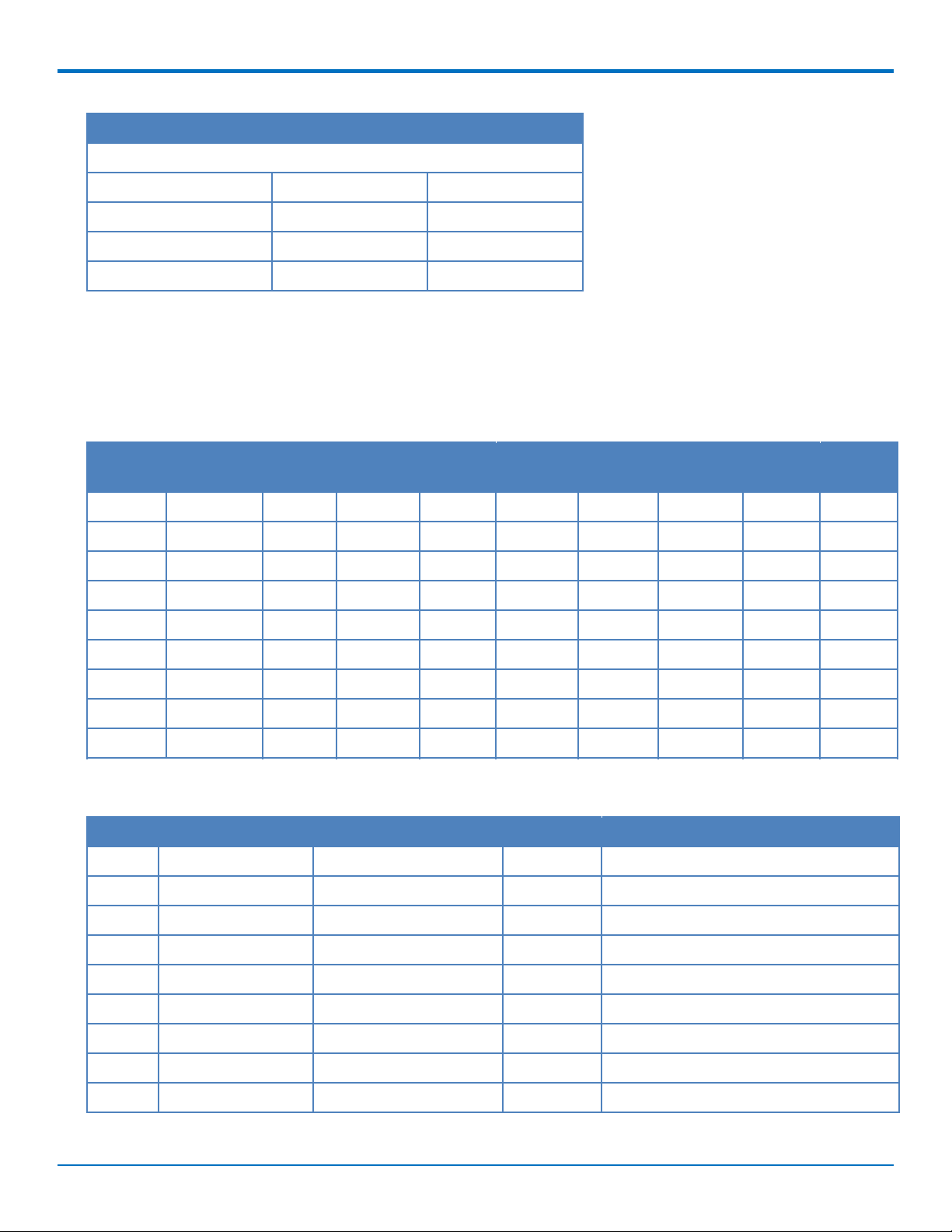
SPECIFICATIONS
Parameter Minimum Maximum
5 Volt Powered
Input Low Level 0 0.8
Input High Level 2.3 5
Output Low Level 0 0.55
Output High Level 3.7 5
Absolute Maximum Rating
All models can run with an input voltage of either 3.3V or 5V. The maximum voltage on any signal pin equals the
input voltage.
Electrical Characteristics Other Pins
Pin Signal
Name
J24 -RESET -- 0.8 2.0 -- -- -- -- --
J25 USB VBUS -0.3 0.8 2.0 8.7 -- -- -- --
J26 GND -- -- -- -- -- -- -- --
J27 USB DP -- 0.8 2 -- -- 0.3 2.8 --
J28 USB DN -- 0.8 2 -- -- 0.3 2.8 --
J41 GND -- -- -- -- -- -- -- --
J58 -LED LINK -- -- -- -- 0 0.45 2.85 3.3
J61 VCC -- -- -- -- -- -- -- --
J63 GND -- -- -- -- -- -- -- --
VIL Min VIL Max VIH Min VIH Max VOL Min VOL Max VOH Min VOH Max
Pinout Specifications
Pin Signal Name Logic Level Voltage
J24 –RESET 3.3 – 5.0 I Device reset (active low)
J25 USB VBUS 3.3 – 5.0 I USB power supply input
1
In/Out Description
J26 GND GND GND Ground
J27 USB DP 3.3 I/O USB data
J28 USB DN 3.3 I/O USB data
J33 –RTS 5.0 I Request to send (active low)
J34 –RXD 5.0 O Received data (active low)
J35 –TXD 5.0 I Transmitted data (active low)
J36 –RI 5.0 O Ring indicator (active low)
12 SocketModem®Cell MTSMC-LSP3 Device Guide
Page 13
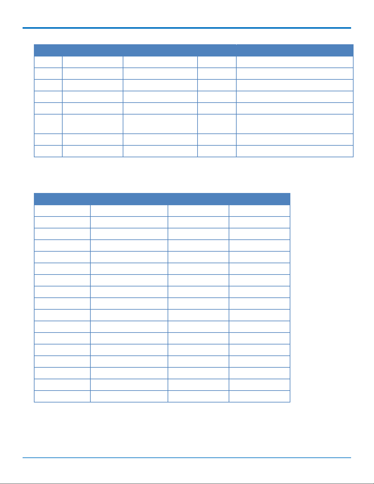
SPECIFICATIONS
Pin Signal Name Logic Level Voltage
1
In/Out Description
J37 –DSR 5.0 O Data set ready (active low)
J38 –CTS 5.0 O Clear to send (active low)
J39 –DCD 5.0 O Data carrier detect (active low)
J40 –DTR 5.0 I Data terminal ready (active low)
J41 GND GND GND Ground
J58 –LED LINK 3.3 O Link status (active low, can sink up to
150mA)
J61 VCC 5.0 PWR DC input power
J63 GND GND GND Ground
1
A hyphen (-) indicates a range of acceptable logic levels.
Pin Availability by Build
Pin Signal Name Serial Only USB Only
J24 –RESET X X
J25 USB VBUS X
J26 GND X X
J27 USB DP X
J28 USB DN X
J33 –RTS X
J34 –RXD X
J35 –TXD X
J36 –RI X
J37 –DSR X
J38 –CTS X
J39 –DCD X
J40 –DTR X
J41 GND X X
J58 –LED LINK X
J61 VCC X X
J63 GND X X
SocketModem®Cell MTSMC-LSP3 Device Guide 13
Page 14
SPECIFICATIONS
Power Measurements
Multi-Tech Systems, Inc. recommends that you incorporate a 10% buffer into your power source when determining
product load.
Note:
The following notes apply to the following tables.
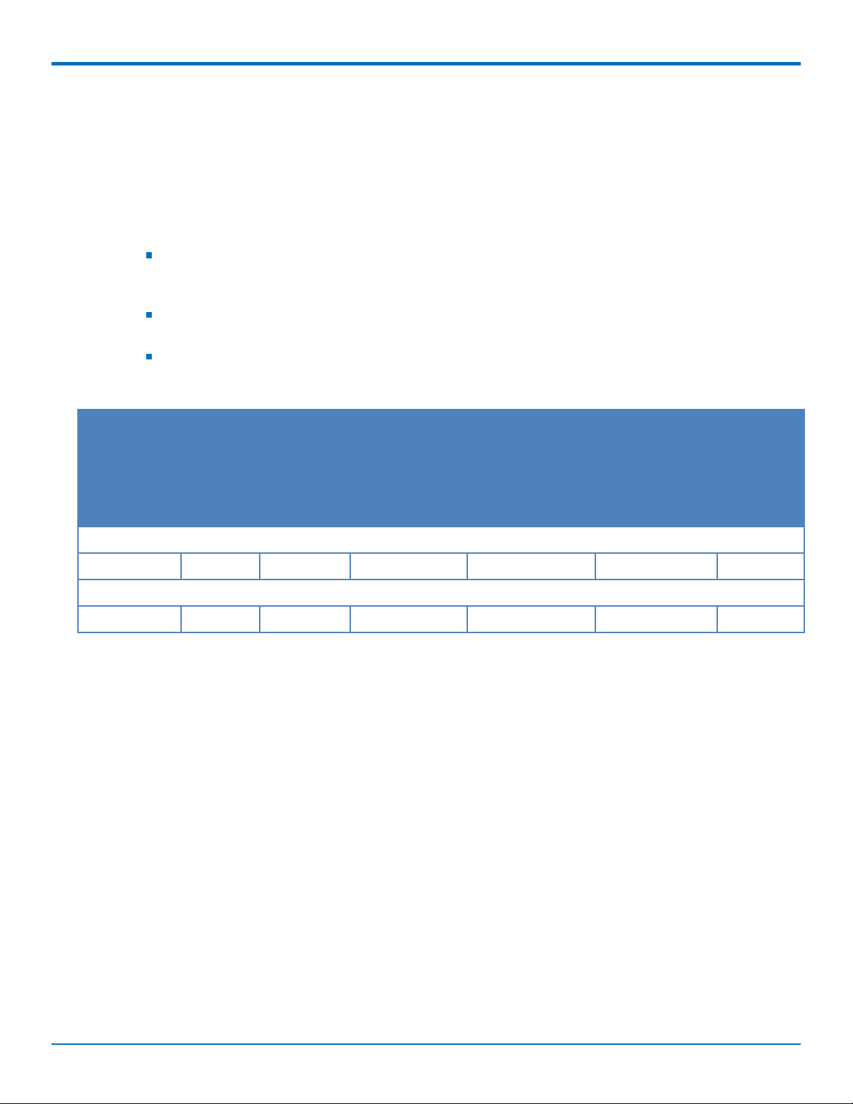
Tx Pulse: The average peak current during a GSM850 transmission burst period or HSDPA/LTE
connection. The transmission burst duration for GSM850 can vary, depending on what transmission
scheme is being deployed (GPRS Class 8, Class 10, GSM, etc.).
Maximum Power: The continuous current during maximum data rate with the radio transmitter at
maximum power.
Inrush Charge: The input current during power up, or a reset.
MTSMC-LSP3 Power Draw
Radio Protocol Sleep
Mode
3.3 Volts
LTE 11 mA 29 mA 86 mA 855 mA 948 mA 0.457 mC
5 Volts
LTE 7 mA 18 mA 55 mA 551 mA 624 mA 0.520 mC
Live
Connection
with SIM
Installed, No
Data
Cellular
Connection Idle,
No Data
Average
Measured Current
at Maximum
Power
TX Pulse (Avg)
Amplitude
Current for
GSM850 or Peak
Current for
HSDPA/LTE
Total Inrush
Charge
Measured
in
Millicoulom
bs
14 SocketModem®Cell MTSMC-LSP3 Device Guide
Page 15
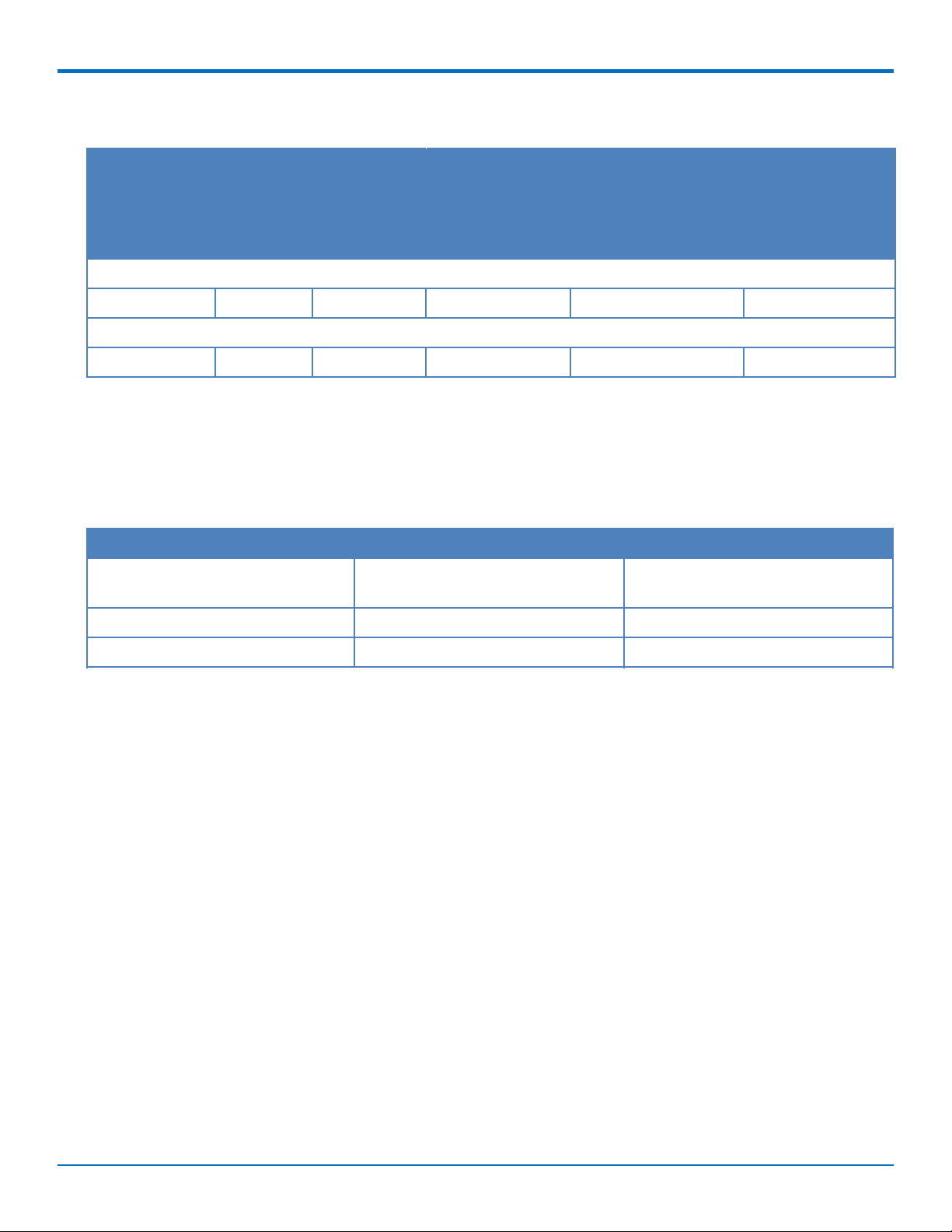
MTSMC-LSP3-U Power Draw
SPECIFICATIONS
Radio Protocol Live
Connection
with SIM
Installed,
No Data
3.3 Volts
LTE 44 mA 102 mA 985 mA 1.11A 0.457 mC
5 Volts
LTE 25 mA 69 mA 603 mA 676 mA 0.520 mC
Cellular
Connection
Idle, No Data
Average Measured
Current at
Maximum Power
TX Pulse (Avg)
Amplitude Current for
GSM850 or Peak
Current for HSDPA/LTE
Total Inrush Charge
Measured in
Millicoulombs
Mounting Hardware
The board has three mounting holes at corners. Use #4 or M3 hardware for mounting the SocketModem to the
board. Refer to the Mechanical Drawings for more information.
Recommended Parts
Manufacturer Part Part Number
PEM (Penn Engineering &
Manufacturing)
Surface Mount Standoff SMTSO-M3-4ET
RAF Electronic Hardware 3/16” Hex Female Standoff 2051T-440-S-12-Zinc
RAF Electronic Hardware 4.5mm Hex Female Standoff 1251-3005-S-12-Zinc
SocketModem®Cell MTSMC-LSP3 Device Guide 15
Page 16
ANTENNAS
Chapter 4 – Antennas
Antenna System Cellular Devices
The antenna system is defined as the UFL connection point from the device through the cable and antenna. Device
performance depends on implementation and antenna system design. Integrating the antenna system is a critical
part of the design process; therefore, it is essential to consider it early so the performance is not compromised.
Requirements for Cellular Antennas with regard to FCC/IC Compliance
The antenna must be the same type, with similar performance and in- and out-of-band radiation patterns as the
listed antenna. The antenna used must stay below the FCC/IC maximum gain.
For our bundles, MultiTech may change antennas over time. The listed antenna(s) is used as a reference or was
shipping when this document was last updated.
LTE Antenna
The cellular radio portion of the device is approved with the following antenna or for alternate antennas meeting
the given specifications. If using a different antenna, ensure
Manufacturer: Wieson Technologies
Description: LTE Antenna
Model Number: GY115-Big Type
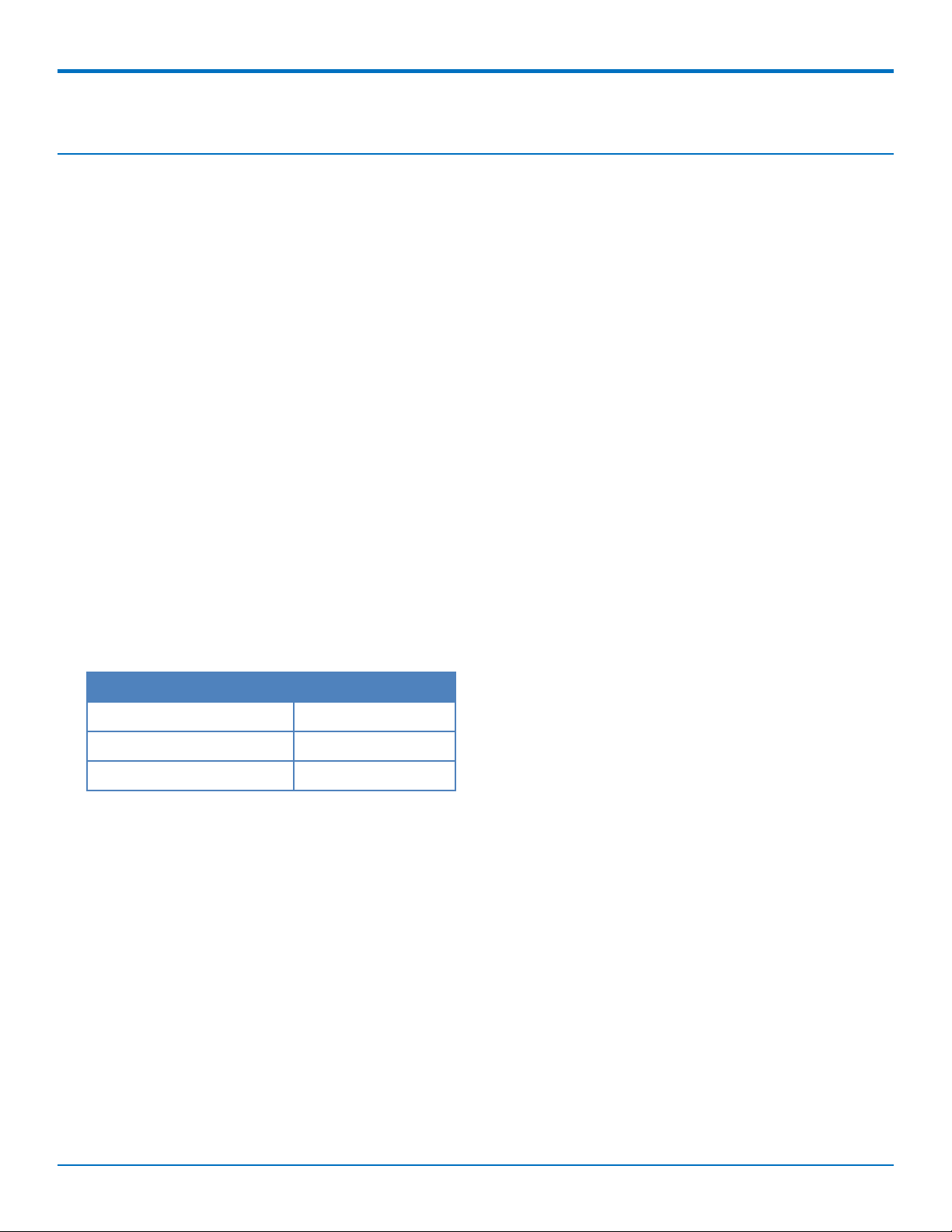
MultiTech ordering information:
Model Quantity
ANLTE4-2HRA 2
ANLTE4-10HRA 10
ANLTE4-50HRA 50
LTE Antenna Diversity
Antenna diversity uses two receive antennas to improve the downlink connection (cell tower to mobile). It has no
effect on the uplink (mobile to cell tower).
Antenna diversity is useful in environments where the signal arrives at the device after bouncing off or around
buildings or other objects. The bounced signal may be attenuated by going through semi-transparent (to the
signal) objects. Each signal alteration can change its magnitude, phase, orientation, or polarization. This complex
environment can exist in cities, inside buildings or in traffic. In this environment, signal paths from the cell tower
form an interference pattern of peaks and nulls. These peaks and nulls can be very close together.
Antenna diversity provides an advantage in complex environments because if one receive antenna has a poor
signal due to an interference null pattern, the other antenna is likely not in the null and has better reception. The
radio compares the reception from both receive antennas and uses the one with the strongest signal.
Important: You must deploy with two antennas, unless your carrier has authorized you to deploy with one
antenna.
16 SocketModem®Cell MTSMC-LSP3 Device Guide
Page 17

ANTENNAS
Selecting Antennas
Select an antenna based on your product and application. Typically, both antennas are the same and either can be
the main receive antenna.
Placing External Antennas
Antennas are usually a quarter wavelength apart from each other. With multiband radios where the quarter
wavelengths in each band are diverse from each other, this rule may not be practical. Choose spacing based on the
band used most often or the band with connection difficulty. Some environments are harsher on particular bands.
MultiTech products have antenna connectors at the best spacing for the product size.
Placing antennas in close proximity to each other is not optimal, but you can do it if necessary. It depends on the
signal strength to and from each antenna.
If the antennas are too close together for your application, use a similar antenna on a short cable for the second
receive only antenna.
Placing GPS Antennas
GPS antennas need a clear view of the sky. Position the GPS antenna so the diversity antennas do not block its
view of the sky.
Antenna Approvals and Safety Considerations
Note the following:
Carriers conduct antenna diversity tests.
There are no EMC concerns about antenna diversity.
All antennas need to have a minimum flammability rating.
Safety requirements depend on your final product.
Unless otherwise noted, antennas certified by MultiTech are not approved for outdoor use. Do not extend
these antennas outside of any building.
Diversity and Power Draw
There are no significant power draw differences.
OEM Integration
FCC & IC Information to Consumers
The user manual for the consumer must contain the statements required by the following FCC and IC regulations:
47 C.F.R. 15.19(a)(3), 15.21, 15.105 and RSS-Gen Issue 3, Dec 2010; 7.1.2 and 7.1.3
FCC Grant Notes
The OEM should follow all the grant notes listed below. Otherwise, further testing and device approvals may be
necessary.
FCC Definitions
Portable: (§2.1093) — A portable device is defined as a transmitting device designed to be used so that the
radiating structure(s) of the device is/are within 20 centimeters of the body of the user.
SocketModem®Cell MTSMC-LSP3 Device Guide 17
Page 18

ANTENNAS
Mobile: (§2.1091) — A mobile device is defined as a transmitting device designed to be used in other than fixed
locations and to generally be used in such a way that a separation distance of at least 20 centimeters is normally
maintained between the transmitter’s radiating structure(s) and the body of the user or nearby persons.
Actual content pending Grant: This device is a mobile device with respect to RF exposure compliance. The
antenna(s) used for this transmitter must be installed to provide a separation distance of at least 20 cm from all
persons, and must not be collocated or operate in conjunction with any other antenna or transmitter except in
accordance with FCC multi-transmitter product guidelines. Installers and end-users must be provided with specific
information required to satisfy RF exposure compliance for installations and final host devices. (See note under
Grant Limitations.) Compliance of this device in all final host configurations is the responsibility of the Grantee.
Note: Host design configurations constituting a device for portable use (<20 cm from human body) require
separate FCC/IC approval.
Note: Only use antennas approved respectively as listed for the unlicensed radios (Bluetooth/Wi-Fi)
Host Labeling
The following statements are required to be on the host label:
This device contains FCC ID: {Add the FCC ID of the specific device}
This device contains equipment certified under IC ID: {Add the IC ID of the specific device}
For additional labeling requirements, see the product's Labeling Requirements. For the FCC and IC IDs, see specific
certificate information in the Regulatory Statement chapter.
18 SocketModem®Cell MTSMC-LSP3 Device Guide
Page 19

SAFETY INFORMATION
Chapter 5 – Safety Information
Handling Precautions
To avoid damage due to the accumulation of static charge, use proper precautions when handling any cellular
device. Although input protection circuitry has been incorporated into the devices to minimize the effect of static
build-up, use proper precautions to avoid exposure to electronic discharge during handling and mounting the
device.
Radio Frequency (RF) Safety
Due to the possibility of radio frequency (RF) interference, it is important that you follow any special regulations
regarding the use of radio equipment. Follow the safety advice given below.
Operating your device close to other electronic equipment may cause interference if the equipment is
inadequately protected. Observe any warning signs and manufacturers’ recommendations.
Different industries and businesses restrict the use of cellular devices. Respect restrictions on the use of
radio equipment in fuel depots, chemical plants, or where blasting operations are in process. Follow
restrictions for any environment where you operate the device.
Do not place the antenna outdoors.
Switch OFF your wireless device when in an aircraft. Using portable electronic devices in an aircraft may
endanger aircraft operation, disrupt the cellular network, and is illegal. Failing to observe this restriction
may lead to suspension or denial of cellular services to the offender, legal action, or both.
Switch OFF your wireless device when around gasoline or diesel-fuel pumps and before filling your vehicle
with fuel.
Switch OFF your wireless device in hospitals and any other place where medical equipment may be in use.
Sécurité relative aux appareils à radiofréquence (RF)
À cause du risque d'interférences de radiofréquence (RF), il est important de respecter toutes les réglementations
spéciales relatives aux équipements radio. Suivez les conseils de sécurité ci-dessous.
Utiliser l'appareil à proximité d'autres équipements électroniques peut causer des interférences si les
équipements ne sont pas bien protégés. Respectez tous les panneaux d'avertissement et les
recommandations du fabricant.
Certains secteurs industriels et certaines entreprises limitent l'utilisation des appareils cellulaires. Respectez
ces restrictions relatives aux équipements radio dans les dépôts de carburant, dans les usines de produits
chimiques, ou dans les zones où des dynamitages sont en cours. Suivez les restrictions relatives à chaque
type d'environnement où vous utiliserez l'appareil.
Ne placez pas l'antenne en extérieur.
Éteignez votre appareil sans fil dans les avions. L'utilisation d'appareils électroniques portables en avion est
illégale: elle peut fortement perturber le fonctionnement de l'appareil et désactiver le réseau cellulaire. S'il
ne respecte pas cette consigne, le responsable peut voir son accès aux services cellulaires suspendu ou
interdit, peut être poursuivi en justice, ou les deux.
Éteignez votre appareil sans fil à proximité des pompes à essence ou de diesel avant de remplir le réservoir
de votre véhicule de carburant.
SocketModem®Cell MTSMC-LSP3 Device Guide 19
Page 20

SAFETY INFORMATION
Éteignez votre appareil sans fil dans les hôpitaux ou dans toutes les zones où des appareils médicaux sont
susceptibles d'être utilisés.
Interference with Pacemakers and Other Medical Devices
Potential interference
Radio frequency energy (RF) from cellular devices can interact with some electronic devices. This is
electromagnetic interference (EMI). The FDA helped develop a detailed test method to measure EMI of implanted
cardiac pacemakers and defibrillators from cellular devices. This test method is part of the Association for the
Advancement of Medical Instrumentation (AAMI) standard. This standard allows manufacturers to ensure that
cardiac pacemakers and defibrillators are safe from cellular device EMI.
The FDA continues to monitor cellular devices for interactions with other medical devices. If harmful interference
occurs, the FDA will assess the interference and work to resolve the problem.
Precautions for pacemaker wearers
If EMI occurs, it could affect a pacemaker in one of three ways:
Stop the pacemaker from delivering the stimulating pulses that regulate the heart's rhythm.
Cause the pacemaker to deliver the pulses irregularly.
Cause the pacemaker to ignore the heart's own rhythm and deliver pulses at a fixed rate.
Based on current research, cellular devices do not pose a significant health problem for most pacemaker wearers.
However, people with pacemakers may want to take simple precautions to be sure that their device doesn't cause
a problem.
Keep the device on the opposite side of the body from the pacemaker to add extra distance between the
pacemaker and the device.
Avoid placing a turned-on device next to the pacemaker (for example, don’t carry the device in a shirt or
jacket pocket directly over the pacemaker).
Vehicle Safety
When using your device in a vehicle:
Do not use this device while driving.
Respect national regulations on the use of cellular devices in vehicles.
If incorrectly installed in a vehicle, operating the wireless device could interfere with the vehicle’s
electronics. To avoid such problems, use qualified personnel to install the device. The installer should verify
the vehicle electronics are protected from interference.
Using an alert device to operate a vehicle’s lights or horn is not permitted on public roads.
UL evaluated this device for use in ordinary locations only. UL did NOT evaluate this device for installation in
a vehicle or other outdoor locations. UL Certification does not apply or extend to use in vehicles or outdoor
applications.
Device Maintenance
Do not attempt to disassemble the device. There are no user serviceable parts inside.
20 SocketModem®Cell MTSMC-LSP3 Device Guide
Page 21

When maintaining your device:
Do not misuse the device. Follow instructions on proper operation and only use as intended. Misuse could
make the device inoperable, damage the device and/or other equipment, or harm users.
Do not apply excessive pressure or place unnecessary weight on the device. This could result in damage to
the device or harm to users.
Do not use this device in explosive or hazardous environments unless the model is specifically approved for
such use. The device may cause sparks. Sparks in explosive areas could cause explosion or fire and may
result in property damage, severe injury, and/or death.
Do not expose your device to any extreme environment where the temperature or humidity is high. Such
exposure could result in damage to the device or fire. Refer to the device specifications regarding
recommended operating temperature and humidity.
Do not expose the device to water, rain, or spilled beverages. Unless the device is IP67 rated, it is not
waterproof.It is not waterproof. Exposure to liquids could result in damage to the device.
Do not place the device alongside computer discs, credit or travel cards, or other magnetic media. The
information contained on discs or cards may be affected by the device.
Using accessories, such as antennas, that MultiTech has not authorized or that are not compliant with
MultiTech's accessory specifications may invalidate the warranty.
SAFETY INFORMATION
If the device is not working properly, contact MultiTech Technical Support.
User Responsibility
Respect all local regulations for operating your wireless device. Use the security features to block unauthorized use
and theft.
SocketModem®Cell MTSMC-LSP3 Device Guide 21
Page 22

REGULATORY INFORMATION
Chapter 6 – Regulatory Information
47 CFR Part 15 Regulation Class B Devices
This equipment has been tested and found to comply with the limits for a Class B digital device, pursuant to part
15 of the FCC Rules. These limits are designed to provide reasonable protection against harmful interference in a
residential installation. This equipment generates, uses, and can radiate radio frequency energy and, if not installed
and used in accordance with the instructions, may cause harmful interference to radio communications. However,
there is no guarantee that interference will not occur in a particular installation. If this equipment does cause
harmful interference to radio or television reception, which can be determined by turning the equipment off and
on, the user is encouraged to try to correct the interference by one or more of the following measures:
Reorient or relocate the receiving antenna.
Increase the separation between the equipment and receiver.
Connect the equipment into an outlet on a circuit different from that to which the receiver is connected.
Consult the dealer or an experienced radio/TV technician for help.
Warning: Changes or modifications to this unit not expressly approved by the party responsible for compliance
could void the user’s authority to operate the equipment.
22 SocketModem®Cell MTSMC-LSP3 Device Guide
Page 23
FCC Grant Information
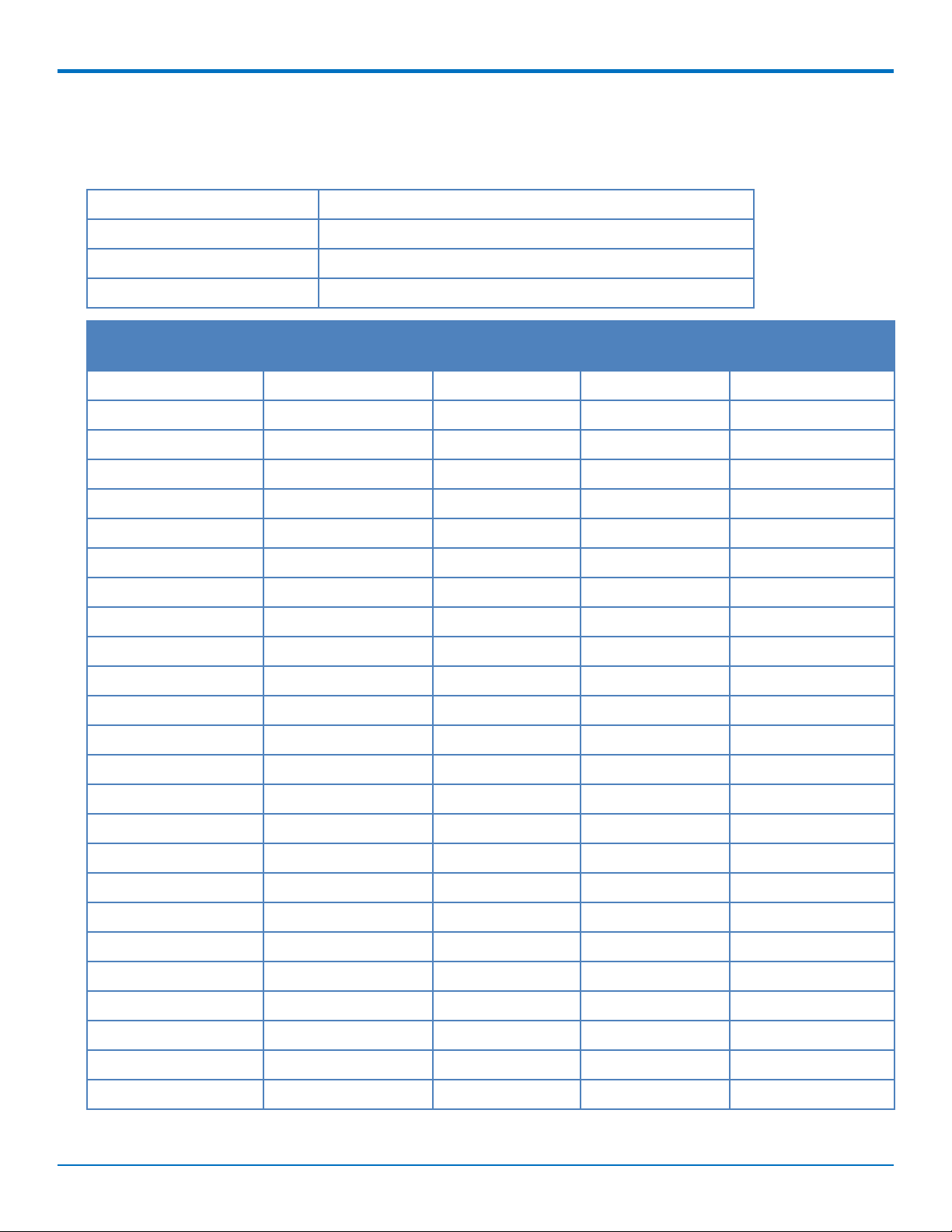
FCC Part 15
FCC Identifier: RI7LE910C1NS
Equipment Class: PCS Licensed Transmitter
Notes: Wireless Module
Approval: Single Modular
REGULATORY INFORMATION
FCC Rule Parts Frequency Range
(MHz)
24E 1850.7 -1909.3 0.271 2.5 PM 1M08G
24E 1850.7 -1909.3 0.211 2.5 PM 2M69G
24E 1851.5 -1908.5 0.213 2.5 PM 2M69W
24E 1852.5 -1907.5 0.261 2.5 PM 4M48G
24E 1852.5 -1907.5 0.209 2.5 PM 4M48W
24E 1855.0 -1905.0 0.265 2.5 PM 8M93G
24E 1855.0 -1905.0 0.231 2.5 PM 4M91W
24E 1857.5 - 1902.5 0.264 2.5 PM 13M4G
24E 1857.5 - 1902.5 0.229 2.5 PM 5M07W
24E 1860.0 - 1900.0 0.241 2.5 PM 17M9G
24E 1860.0 - 1900.0 0.183 2.5 PM 5M13W
27 1710.7 - 1754.3 0.234 2.5 PM 1M08G
27 1710.7 - 1754.3 0.184 2.5 PM 1M08W
27 1711.5 - 1753.5 0.227 2.5 PM 2M69G
Output Watts Frequency
Tolerance
Emission Designators
27 1711.5 - 1753.5 0.195 2.5 PM 2M69W
27 1712.5 - 1752.5 0.222 2.5 PM 4M48G
27 1712.5 - 1752.5 0.17 2.5 PM 4M49W
27 1715.0 - 1750.0 0.245 2.5 PM 8M93G
27 1715.0 - 1750.0 0.209 2.5 PM 4M93W
27 1717.5 - 1747.5 0.252 2.5 PM 13M4G
27 1717.5 - 1747.5 0.218 2.5 PM 5M04W
27 1720.0 - 1745.0 0.2355 2.5 PM 17M8G
27 1720.0 - 1745.0 0.172 2.5 PM 5M15W
22H 824.7 - 848.3 0.212 2.5 PM 1M08G
22H 824.7 - 848.3 0.159 2.5 PM 1M08W
SocketModem®Cell MTSMC-LSP3 Device Guide 23
Page 24

REGULATORY INFORMATION
FCC Rule Parts Frequency Range
(MHz)
Output Watts Frequency
Tolerance
Emission Designators
22H 825.5 - 847.5 0.218 2.5 PM 2M69G
22H 825.5 - 847.5 0.168 2.5 PM 2M69W
22H 826.5 - 846.5 0.217 2.5 PM 4M49G
22H 826.5 - 846.5 0.167 2.5 PM 4M49W
22H 829.0 - 844.0 0.224 2.5 PM 8M94G
22H 829.0 - 844.0 0.187 2.5 PM 4M93W
27 699.7 - 715.3 0.186 2.5 PM 1M08G
27 699.7 - 715.3 0.155 2.5 PM 1M09W
27 700.5 - 714.5 0.186 2.5 PM 2M69G
27 700.5 - 714.5 0.151 2.5 PM 2M69W
27 701.5 - 713.5 0.182 2.5 PM 4M48G
27 701.5 - 713.5 0.146 2.5 PM 4M48W
27 704.0 - 711.0 0.193 2.5 PM 8M96G
27 704.0 - 711.0 0.176 2.5 PM 4M95W
24E 1850.7 - 1914.3 0.242 2.5 PM 1M08G
24E 1850.7 - 1914.3 0.193 2.5 PM 1M08W
24E 1851.5 - 1913.5 0.244 2.5 PM 2M69G
24E 1851.5 - 1913.5 0.204 2.5 PM 2M69W
24E 1852.5 - 1912.5 0.244 2.5 PM 4M48G
24E 1852.5 - 1912.5 0.192 2.5 PM 4M48W
Ouput power is conducted. Single Modular Approval. This device is approved for mobile and fixed use with respect
to RF exposure compliance. The antenna of this transmitter must provide a separation distance of at least 20 cm
from all persons. Installers and end-users must be provided with antenna installation instructions and transmitter
operating conditions and instructions for satisfying RF exposure compliance. The final product operating with this
transmitter must include operating instructions and antenna installation instructions, for end-users and installers
to satisfy RF exposure compliance requirements. Multi-transmitter, supporting simultaneous transmission
configurations, have not been evaluated and shall be evaluated according to KDB Publication 447498 and §15.31(h)
and §15.31(k) composite system and § 2.1 end product terms and concepts. Compliance of this device in all final
product configurations is the responsibility of the Grantee. Installation of this device into specific final products
may require the submission of a Class II permissive change application containing data pertinent to RF Exposure,
emissions and host/module authentication, or new application if appropriate.
24 SocketModem®Cell MTSMC-LSP3 Device Guide
Page 25
ENVIRONMENTAL NOTICES
Chapter 7 – Environmental Notices
Waste Electrical and Electronic Equipment Statement
Note: This statement may be used in documentation for your final product applications.
WEEE Directive
The WEEE Directive places an obligation on EU-based manufacturers, distributors, retailers, and importers to takeback electronics products at the end of their useful life. A sister directive, ROHS (Restriction of Hazardous
Substances) complements the WEEE Directive by banning the presence of specific hazardous substances in the
products at the design phase. The WEEE Directive covers all MultiTech products imported into the EU as of August
13, 2005. EU-based manufacturers, distributors, retailers and importers are obliged to finance the costs of recovery
from municipal collection points, reuse, and recycling of specified percentages per the WEEE requirements.
Instructions for Disposal of WEEE by Users in the European Union
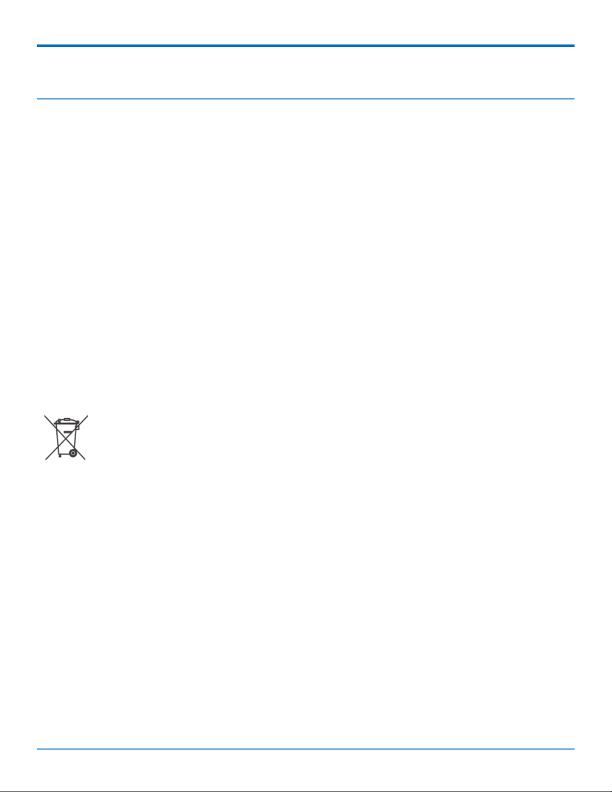
The symbol shown below is on the product or on its packaging, which indicates that this product must not be
disposed of with other waste. Instead, it is the user's responsibility to dispose of their waste equipment by handing
it over to a designated collection point for the recycling of waste electrical and electronic equipment. The separate
collection and recycling of your waste equipment at the time of disposal will help to conserve natural resources
and ensure that it is recycled in a manner that protects human health and the environment. For more information
about where you can drop off your waste equipment for recycling, please contact your local city office, your
household waste disposal service or where you purchased the product.
July, 2005
REACH Statement
Registration of Substances
Multi-Tech Systems, Inc. confirms that none of its products or packaging contain any of the Substances of Very
High Concern (SVHC) on the REACH Candidate List, in a concentration above the 0.1% by weight allowable limit
The latest 197 substances restricted per the REACH Regulation were last updated January 2019. Refer to the
following for the most current candidate list of substances: http://echa.europa.eu/candidate-list-table.
Restriction of the Use of Hazardous Substances (RoHS)
Multi-Tech Systems, Inc.
Certificate of Compliance
2015/863
SocketModem®Cell MTSMC-LSP3 Device Guide 25
Page 26

ENVIRONMENTAL NOTICES
Multi-Tech Systems, Inc. confirms that its embedded products comply with the chemical concentration limitations
set forth in the directive 2015/863 of the European Parliament (Restriction of the use of certain Hazardous
Substances in electrical and electronic equipment - RoHS).
These MultiTech products do not contain the following banned chemicals1:
Lead, [Pb] < 1000 PPM
Mercury, [Hg] < 100 PPM
Cadmium, [Cd] < 100 PPM
Hexavalent Chromium, [Cr+6] < 1000 PPM
Polybrominated Biphenyl, [PBB] < 1000 PPM
Polybrominated Diphenyl Ethers, [PBDE] < 1000 PPM
Bis(2-Ethylhexyl) phthalate (DEHP): < 1000 ppm
Benzyl butyl phthalate (BBP): < 1000 ppm
Dibutyl phthalate (DBP): < 1000 ppm
Diisobutyl phthalate (DIBP): < 1000 ppm
Environmental considerations:
Moisture Sensitivity Level (MSL) =1
Maximum Soldering temperature = 260C (in SMT reflow oven)
1
Lead usage in some components is exempted by the following RoHS annex, therefore higher lead concentration
would be found in some modules (>1000 PPM);
- Resistors containing lead in a glass or ceramic matrix compound.
26 SocketModem®Cell MTSMC-LSP3 Device Guide
Page 27

SPRINT ACTIVATION AND OMA-DM COMMANDS (LSP3)
Chapter 8 – Sprint Activation and OMA-DM Commands (LSP3)
All applications interacting with Sprint approved MultiTech devices must be written in a manner where they do not
interfere/interrupt the Sprint Hands-Free Activation (HFA) process or OMA-DM processes.
If the MultiTech device will be co-located with any other transmitters you will be required to submit your device to
an FCC approved lab for additional testing.
If the Sprint approved MultiTech device/circuit board is embedded into another device/circuit board be aware you
must perform EMC and safety testing on your end device.
For additional information refer to:
S000729 Telit Sprint OMA-DM AT Commands available at
www.multitech.com/documents/publications/reference-guides/S000729_Telit_Sprint_DG_OMADMAT_commands.pdf
For mLinux models, go to: http://www.multitech.net/developer/software/mlinux/using-mlinux/mlinux-
cellular-connection/lsp-device-sprint-lte-activation/
SocketModem®Cell MTSMC-LSP3 Device Guide 27
Page 28
LABELS
Chapter 9 – Labels
Approvals and Certifications
This device is an industry and/or carrier approved modem. In most cases, when integrated and used with an
antenna system that was part of the MultiTech modem certification, additional approvals or certifications are not
required for the device that you develop as long as the following requirements are met:
PTCRB Requirements: The antenna system cannot be altered. The antenna system must be the same type
with similar in-band and out-of-band radiation patterns and maintain the same specifications. Refer to the
FCC grant information for details.
Model Identification: The MultiTech model identification allows the carrier to verify the modem as one of
its approved models. This information is located on the modem's label below the bar code.
Example Labels
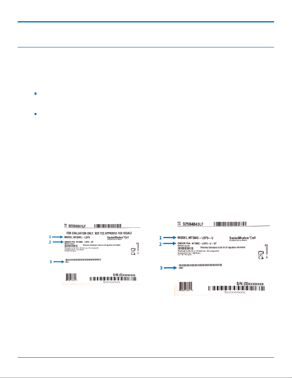
Note: Actual labels vary depending on the regulatory approval markings and content.
This device complies with part 15 of the FCC Rules. Operation is subject to the following two conditions: (1) This
device may not cause harmful interference, and (2) this device must accept any interference received, including
interference that may cause undesired operation.
Label images shown here are not actual size.
1 - Multi-Tech Model Identification.
2 - Multi-Tech Ordering Part Number.
3 - IMEI (International Mobile Equipment Identity).
MTSMC-LSP3 Package
Label
MTSMC-LSP3-U Package Label
28 SocketModem®Cell MTSMC-LSP3 Device Guide
Page 29
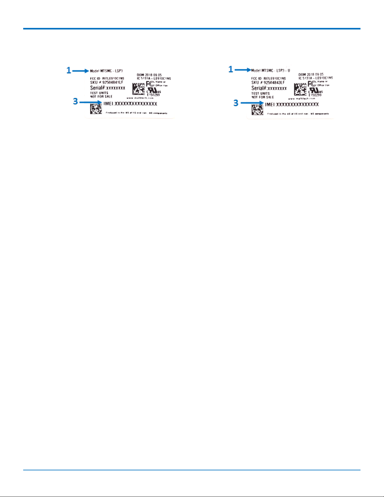
MTSMC-LSP3 Device Label MTSMC-LSP3-U Device Label
LABELS
SocketModem®Cell MTSMC-LSP3 Device Guide 29
Page 30

USING CONNECTION MANAGER
Chapter 10 – Using Connection Manager
Use Connection Manager to:
Install the latest device drivers.
Activate and connect your device to your carrier’s network.
Note:
Connection Manager can install drivers and connect your device regardless of your cellular network;
however, activation is only supported with Verizon, Aeris, Sprint, and some regional carriers. If you
cannot activate your device with Connection Manager, refer to Account Activation for Cellular
Devices.
Switch the firmware in your device to a different carrier (if supported by your device).
Manage cellular connection and automatically reconnect with the keep-alive feature.
View device details.
View line charts of signal level and data rates.
Use a terminal window for communicating with and troubleshooting the device.
Installing Connection Manager
Connection Manager installs the appropriate drivers for USB devices along with the application. Serial devices do
not require drivers.
Note: Attempting to plug in the device before the appropriate drivers are installed can cause the connection to
fail.
To install Connection Manager and the device drivers:
1. Go to https://www.multitech.com/support/connection-manager.
2. Click Connection Manager.
3. Open or unzip the Connection Manager file and run the installer (.msi file).
4. In the MultiTech Connection Manager Setup Wizard, read the end-user license agreement and check I
accept the terms in the License Agreement.
5. Click Next to have the installer automatically disable the native WWAN AutoConfig service in Windows.
The WWAN AutoConfig service manages mobile broadband connections. Connection Manager requires
that this service be disabled.
Note: This page appears only on Windows 10.
6. If a MultiTech device is connected to the computer, disconnect it and click Next.
7. If you use a USB device, check Install the modem driver.
CAUTION: Unless you are certain that the drivers for your USB device are already installed on the
computer, make sure that you check Install the modem driver. Failure to do this will cause the
application to incorrectly detect your device or not detect the device at all.
Note: Because serial devices do not require drivers, it does not matter if you check or uncheck
Install the modem driver for a serial device.
30 SocketModem®Cell MTSMC-LSP3 Device Guide
Page 31

USING CONNECTION MANAGER
8. To specify a folder for Connection Manager, use the default folder or click Change to browse to the folder
you want to use.
9. Click Install.
A separate wizard opens for installing Telit drivers. Some MultiTech devices use embedded modules from
Telit Wireless Solutions to provide cellular connectivity; these devices require Telit drivers.
10. Select Complete setup type.
11. When the drivers are installed, click Finish.
12. In the Setup Wizard, click Finish.
Note:
To open Connection Manager after installation, check Start the MultiTech Connection
Manager when the installation is finished.
After the drivers are installed, you need to restart your computer if prompted by Windows.
If using a USB device, you can connect the device to the carrier's network with Connection Manager. Refer to
Connecting a Device.
If using a serial device, you need to set up the device in Windows Device Manager before connecting the device.
Refer to Setting Up a Serial Device in Windows Device Manager.
Setting Up a Serial Device in Windows Device Manager
To set up the device in Windows Device Manager:
1. Make sure that your desired COM port for the serial device is available.
2. Connect the serial device to the PC.
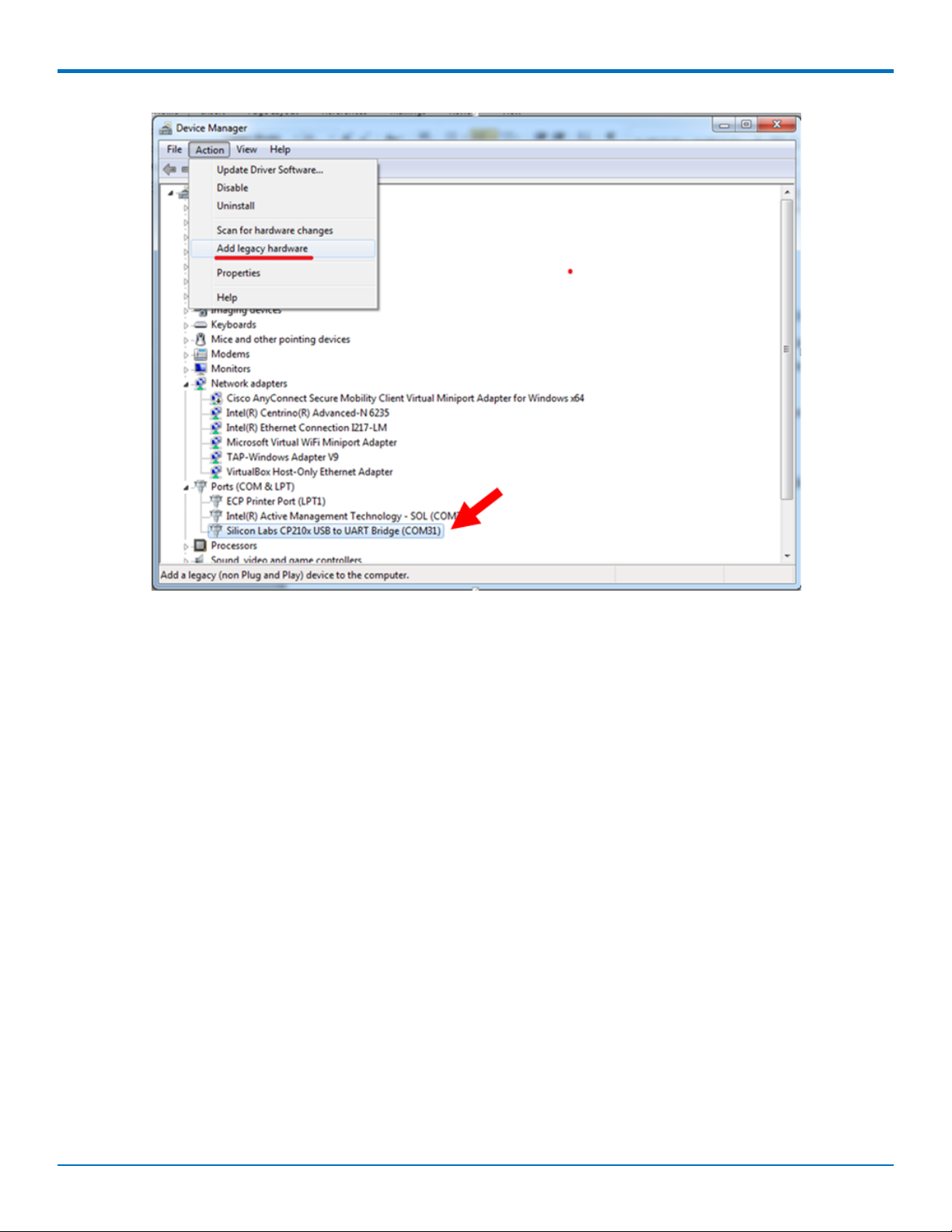
3. Go to Control Panel > Device Manager. Make a note of the COM port number for the connected device
(in COM Ports).
Example: The COM port is COM31.
4. Go to Action > Add legacy hardware.
SocketModem®Cell MTSMC-LSP3 Device Guide 31
Page 32
USING CONNECTION MANAGER
5. In the Add Hardware Wizard:
a. Click Next.
b. Select Install the hardware that I manually select from a list, then click Next.
c. Select Modems, then click Next.
d. Check Don't detect my modem; I will select it from a list, then click Next.
e. Select Standard Modem Types, then select Standard 33600 bps Modem on the right.
Important: Make sure that you select only Standard 33600 bps Modem. Selecting another model
may cause your device to work incorrectly or fail.
f. Select your COM port, then click Next.
g. Click Finish.
h. Go to Device Manager > Modems and confirm that the device is added.
6. To verify that the device is set up correctly, query the device:
a. Go to Device Manager > Modems, right-click Standard 33600 bps Modem, and select Properties.
b. On the Diagnostics tab, click Query Modem.
Note: The device cannot be queried if the Connection Manager is running and using the device's
port.
If the device is ready, diagnostic information from the device appears in the box above.
To connect the device to your carrier's network, refer to Connecting a Device.
32 SocketModem®Cell MTSMC-LSP3 Device Guide
Page 33

USING CONNECTION MANAGER
Connecting a Device
Before You Begin
Make sure that your device is connected to the computer where Connection Manager is installed.
Set up the device in Device Manager. Refer to Setting Up a Serial Device in Windows Device Manager .
To connect your device to the carrier's network:
1. Open Connection Manager.
Connection Manager automatically detects the connected device, and the Detect button on the Main tab
changes to Connect. If the application cannot detect the device automatically, click Detect to initiate
device detection manually.
2. If you are connecting the device to this computer for the first time, on the Connection dialog box, provide
values for the connection settings, such as the dial number and access point name (APN).
You may need to ask the carrier for these settings.
a. To monitor Internet connectivity, have Connection Monitor send periodic pings to a host, check
Enable keep-alive and enter the IP address or host name to ping in the Host to ping box. For
example, you can enter the host name google.com or IP address 8.8.8.8.
If the keep-alive check fails, Connection Manager automatically reconnects. When the keep-alive
feature is enabled, the Connection Manager's Main tab displays the keep-alive check status and
when the last ping response was received.
b. If your device supports dual carriers, switch the firmware to the desired carrier by selecting the
carrier in the MNO Firmware list. For example, if your device can switch the firmware between
AT&T and Verizon, select Verizon in the list.
Note:
The MNO Firmware list doesn't appear if your device doesn't support carrier firmware
switching.
When you change the carrier firmware, the modem automatically restarts to apply the
selected firmware.
c. To save the settings, click Apply.
You can change the connection settings on the Connection tab. The Dial number, APN, User name,
and Password cannot be changed after the device is connected.
3. On the Settings tab, select USB Modem or Serial Modem depending on whether you are connecting a
USB or serial device.
4. If you are connecting a serial device, provide the serial settings on the Settings tab:
a. In the Modem type list, select the appropriate modem type.
b. For the other settings, provide the values that match the serial-port settings for the device in Device
Manager.
For Port, expand Ports and notice the COM port number next to the device name. Right-click the
device name, select Properties, and find the values for the other settings on the Port Settings tab.
c. To save the settings, click Apply.
Note:
SocketModem®Cell MTSMC-LSP3 Device Guide 33
Page 34

USING CONNECTION MANAGER
Settings displayed for a USB device on the Settings tab are determined automatically and cannot
be changed.
To set the application to run during Windows startup, check Run application at Windows startup.
To automatically connect to the Internet, check Connect to the Internet automatically.
Selecting Run application at Windows startup and Connect to the Internet automatically is useful in
scenarios where Connection Manager is running on a remote computer. If a power failure occurs on the
computer, these settings ensure the application will restart and reconnect to the Internet when power is
restored.
5. On the Main tab, click Connect.
When a connection is established, the Main tab displays the download and upload speeds, the amount of
traffic sent and received, Connected status, and the signal strength percentage and bars. The statistics on
connection speeds and traffic are available only during a current connection session.
Note:
For serial modems, the signal strength is available only when the device is not connected to the
carrier's network. When connection to the network is established, the last signal strength value is
displayed.
View the details for the current connection on the Details tab.
6. To disconnect the device from the carrier's network, click Disconnect.
Uninstalling Connection Manager
Along with uninstalling Connection Manager, the installed device drivers are also removed.
Before You Begin
Make sure that Connection Manager is not running.
To uninstall Connection Manager:
1. In Windows, go to Control Panel > Programs > Programs and Features.
2. Right-click MultiTech Connection Manager and select Uninstall.
3. Click Yes to confirm that you want to uninstall Connection Manager.
The native Windows WWAN AutoConfig service is automatically enabled.
4. When the message "Are you sure you want to uninstall this product?" appears, click Yes.
Connection Manager and the installed drivers are removed from the computer.
Note: The steps above describe how to uninstall Connection Manager using Control Panel. You can also
uninstall the application by using the installer file (.msi). Double-click the file, in the MultiTech Connection
Manager Setup Wizard, click Next, and then select Remove on the next two pages.
Connection Manager User Interface
Connection Manager consists of the following tabs:
Main
Settings
34 SocketModem®Cell MTSMC-LSP3 Device Guide
Page 35
Connection
Details
Terminal
Charts
USING CONNECTION MANAGER
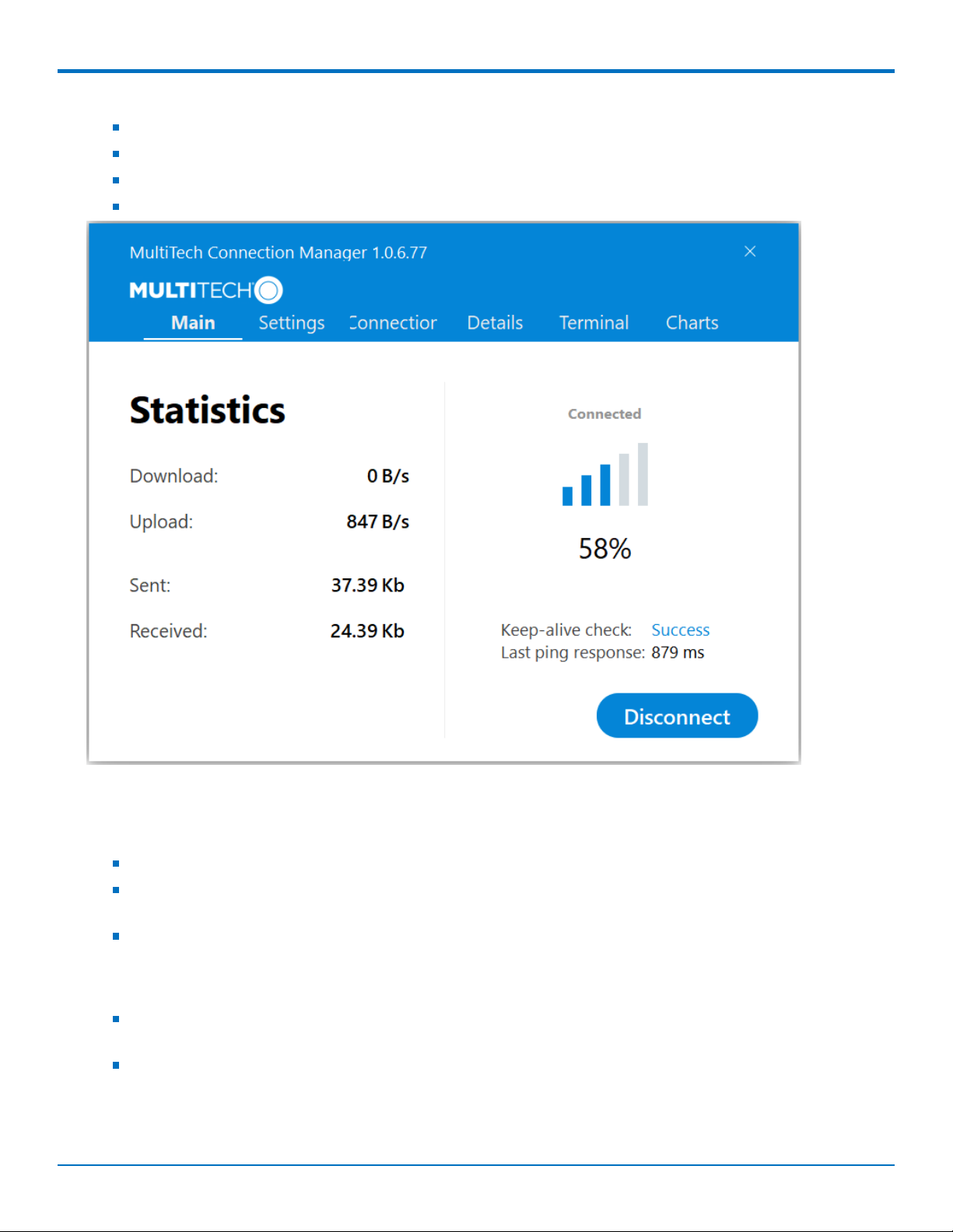
Main tab
The Main tab displays the following:
Status of device connection: Searching, Connecting, Connected, Disconnecting, or Disconnected
The action button, which changes according to the current device connection status: Detect, Connect, or
Disconnect
Signal strength bars and percentage indicator (only when connection to the carrier's network is established)
Note: The signal strength is displayed for a serial device only when the device is not connected to the
carrier's network.
Connection statistics: download and upload speeds, amount of traffic sent and received (only when
connection to the carrier's network is established)
The keep-alive check status and when the last ping response was received if Enable keep-alive check is
checked on the Connection tab.
SocketModem®Cell MTSMC-LSP3 Device Guide 35
Page 36

USING CONNECTION MANAGER
Settings tab
Use the Settings tab to specify the type of device: USB Modem or Serial Modem.
If USB Modem is selected, the tab displays USB settings. These settings cannot be edited.
If Serial Modem is selected, the tab displays the serial settings that match the serial-port settings for the
device. You can edit these settings.
The Settings tab also contains the Run application at Windows startup and Connect to the Internet automatically
options.
Check Run application at Windows startup to open Connection Manager when Windows starts.
Check Connect to the Internet automatically to set Connection Manager to connect to the carrier's network
automatically each time the application opens.
Connection tab
The Connection tab displays the following:
The carrier-provided connection settings.
The Enable keep-alive check box. Check this box to monitor connectivity to the Internet. Check Enable
keep-alive check and enter the IP address or host name to ping in the Host to ping box. Connection
Monitor will send periodic pings to the host. If the keep-alive feature fails, Connection Manager will
automatically reconnect.
The MNO firmware list. If your device supports dual carriers, you can switch the firmware to the other
carrier by selecting the carrier in this list.
Note: The Connection tab isn't available if Connection Manager doesn't detect a device.
Details tab
The Details tab displays the modem details when a device is detected and the connection details when a
connection is established.
Terminal tab
The Terminal tab contains a terminal window to communicate with the connected device by entering AT
commands. For details, refer to the AT Commands reference guide for your device.
Note: When a serial device is connected to the carrier's network, the terminal window isn't available.
Charts tab
The Charts tab contains line charts that graphically represent signal strength and download and upload speeds for
the 2-hour interval.
Troubleshooting
Serial COM port is not available in the Serial Modem Settings
Close Connection Manager and reopen it.
Device is not detected ("No Device")
After following the steps to activate your device, the Main tab still indicates "No Device."
36 SocketModem®Cell MTSMC-LSP3 Device Guide
Page 37

USING CONNECTION MANAGER
Try the following steps:
1. Click the Settings tab and make sure that the appropriate modem type is selected: USB or Serial.
2. If you are connecting a serial device, make sure that all serial modem settings correspond to the
serial modem and serial port configuration.
3. Restart Connection Manager.
4. Disconnect and reconnect the device.
MultiConnect Cell USB Modem is not detected
1. Check the Power and LS LEDs on the device. If they are not continuously lit, then the problem is with
the power supply. Check the cable and connections.
2. USB device: Make sure that the device is connected to the PC and that the correct USB cable is in use.
Connection Manager is not working, and a device connected to the computer is not detected
Connection Manager cannot detect a connected device because the required drivers are not installed. The most
likely cause is that Install the modem drivers was not checked during the installation.
Uninstall and re-install Connection Manager. During the installation, make sure that you check Install the modem
driver. Refer to Uninstalling Connection Manager and Installing Connection Manager.
Connection Manager displays "Device Error" status for a serial device
This error has the following causes and solutions.
Cause Solution
Connection Manager cannot open the COM port that
the device was installed on because the port is being
used by another program.
The wrong COM port is specified for the device on the
Settings tab.
If possible, free up the COM port for the device.
On the Settings tab, select the COM port that matches
the port that the device is installed on and click Apply.
You can look up the port in Device Manager in
Windows. In Device Manager, expand Modems, rightclick the name of your device, and select Properties.
Note the port on the Modem tab.
SocketModem®Cell MTSMC-LSP3 Device Guide 37
Page 38

INDEX
Index
A
activation.......................................................................30
antenna
cellular devices.........................................................16
diversity....................................................................16
LTE............................................................................16
AT#SHDN.......................................................................11
B
build options ...................................................................7
C
certification
FCC ...........................................................................23
Class B ..........................................................................22
Connection Manager
Charts tab.................................................................34
connecting device to carrier's network ...................33
Connection tab.........................................................34
Details tab ................................................................34
installation ...............................................................30
installation of device drivers....................................30
Main tab...................................................................34
overview ..................................................................30
Settings tab ..............................................................34
Terminal tab.............................................................34
troubleshooting .......................................................36
uninstalling...............................................................34
F
FCC
grant notes...............................................................17
FCC certification ............................................................23
FCC Notice
Class B .....................................................................22
H
hazardous substances ...................................................25
host labeling..................................................................17
I
interférence des radiofréquences.................................19
K
KDB 447498 Section 8 ..................................................17
L
labeling
host ..........................................................................17
labels .............................................................................28
LTE
antenna....................................................................16
M
maintenance .................................................................20
D
device
connecting to carrier's network with Connection
Manager...................................................................33
maintenance ............................................................20
device drivers
installation for use with Connection Manager ........30
diversity.........................................................................16
documentation................................................................6
E
electrical characteristics, pins .......................................12
38 SocketModem®Cell MTSMC-LSP3 Device Guide
mechanical drawings....................................................8 9
model location ..............................................................28
mounting hardware ......................................................15
O
OMA DM ......................................................................27
P
power down ..................................................................11
power draw...................................................................14
MTSMC-LSP3............................................................14
MTSMC-LSP3-U ........................................................15
Page 39

INDEX
R
radio frequency interference ........................................19
RoHS..............................................................................25
S
safety
RF interference ........................................................19
vehicle......................................................................20
shutdown ......................................................................11
specifications.................................................................10
Sprint.............................................................................27
static..............................................................................19
sécurité
interférences RF.......................................................19
T
troubleshooting
Connection Manager ...............................................36
U
user responsibility.........................................................21
V
vehicle safety ................................................................20
SocketModem®Cell MTSMC-LSP3 Device Guide 39
 Loading...