

Multitech SocketModem, SocketModem MTSMC-LSP3, SocketModem MTSMC-LSP3-U Device Manual
®
SocketModem
MTSMC-LSP3 Device Guide
Cell

SOCKETMODEM® CELL DEVICE GUIDE
SocketModem®Cell Device Guide
Models: MTSMC-LSP3, MTSMC-LSP3-U
Part Number: S000703, Version 1.2
Copyright
This publication may not be reproduced, in whole or in part, without the specific and express prior written permission signed by an executive officer of
Multi-Tech Systems, Inc. All rights reserved. Copyright © 2019 by Multi-Tech Systems, Inc.
Multi-Tech Systems, Inc. makes no representations or warranties, whether express, implied or by estoppels, with respect to the content, information,
material and recommendations herein and specifically disclaims any implied warranties of merchantability, fitness for any particular purpose and noninfringement.
Multi-Tech Systems, Inc. reserves the right to revise this publication and to make changes from time to time in the content hereof without obligation of
Multi-Tech Systems, Inc. to notify any person or organization of such revisions or changes.
Trademarks and Registered Trademarks
Multi-Tech, and the Multi-Tech logo, and SocketModem are trademarks and registered trademarks of Multi-Tech Systems, Inc. All other products and
technologies are the trademarks or registered trademarks of their respective holders.
Legal Notices
The MultiTech products are not designed, manufactured or intended for use, and should not be used, or sold or re-sold for use, in connection with
applications requiring fail-safe performance or in applications where the failure of the products would reasonably be expected to result in personal injury or
death, significant property damage, or serious physical or environmental damage. Examples of such use include life support machines or other life
preserving medical devices or systems, air traffic control or aircraft navigation or communications systems, control equipment for nuclear facilities, or
missile, nuclear, biological or chemical weapons or other military applications (“Restricted Applications”). Use of the products in such Restricted
Applications is at the user’s sole risk and liability.
MULTITECH DOES NOT WARRANT THAT THE TRANSMISSION OF DATA BY A PRODUCT OVER A CELLULAR COMMUNICATIONS NETWORK WILL BE
UNINTERRUPTED, TIMELY, SECURE OR ERROR FREE, NOR DOES MULTITECH WARRANT ANY CONNECTION OR ACCESSIBILITY TO ANY CELLULAR
COMMUNICATIONS NETWORK. MULTITECH WILL HAVE NO LIABILITY FOR ANY LOSSES, DAMAGES, OBLIGATIONS, PENALTIES, DEFICIENCIES, LIABILITIES,
COSTS OR EXPENSES (INCLUDING WITHOUT LIMITATION REASONABLE ATTORNEYS FEES) RELATED TO TEMPORARY INABILITY TO ACCESS A CELLULAR
COMMUNICATIONS NETWORK USING THE PRODUCTS.
The MultiTech products and the final application of the MultiTech products should be thoroughly tested to ensure the functionality of the MultiTech
products as used in the final application. The designer, manufacturer and reseller has the sole responsibility of ensuring that any end user product into
which the MultiTech product is integrated operates as intended and meets its requirements or the requirements of its direct or indirect customers.
MultiTech has no responsibility whatsoever for the integration, configuration, testing, validation, verification, installation, upgrade, support or maintenance
of such end user product, or for any liabilities, damages, costs or expenses associated therewith, except to the extent agreed upon in a signed written
document. To the extent MultiTech provides any comments or suggested changes related to the application of its products, such comments or suggested
changes is performed only as a courtesy and without any representation or warranty whatsoever.
Contacting MultiTech
Knowledge Base
The Knowledge Base provides immediate access to support information and resolutions for all MultiTech products. Visit http://www.multitech.com/kb.go.
Support Portal
To create an account and submit a support case directly to our technical support team, visit: https://support.multitech.com.
Support
Business Hours: M-F, 8am to 5pm CT
Country By Email By Phone
Europe, Middle East, Africa: support@multitech.co.uk +(44) 118 959 7774
U.S., Canada, all others: support@multitech.com (800) 972-2439 or (763) 717-5863
Warranty
To read the warranty statement for your product, visit https://www.multitech.com/legal/warranty. For other warranty options, visit
www.multitech.com/es.go.
World Headquarters
Multi-Tech Systems, Inc.
2205 Woodale Drive, Mounds View, MN 55112
Phone: (800) 328-9717 or (763) 785-3500
Fax (763) 785-9874
2 SocketModem®Cell MTSMC-LSP3 Device Guide

CONTENTS
Contents
Chapter 1 – Product Overview ................................................................................................................................. 6
Product Overview.......................................................................................................................................................... 6
Documentation ............................................................................................................................................................. 6
Product Build Options ................................................................................................................................................... 7
Chapter 2 – Mechanical Drawings............................................................................................................................ 8
MTSMC-LSP3 ................................................................................................................................................................. 8
MTSMC-LSP3-U ............................................................................................................................................................. 9
Chapter 3 – Specifications...................................................................................................................................... 10
MTSMC-LSP3 and MTSMC-LSP3-U Specifications....................................................................................................... 10
Powering Down Your Device ...................................................................................................................................... 11
UART DC Electrical Characteristics.............................................................................................................................. 11
Absolute Maximum Rating........................................................................................................................................ 12
Electrical Characteristics Other Pins ........................................................................................................................... 12
Pinout Specifications................................................................................................................................................... 12
Pin Availability by Build............................................................................................................................................... 13
Power Measurements................................................................................................................................................. 14
MTSMC-LSP3 Power Draw ........................................................................................................................................ 14
MTSMC-LSP3-U Power Draw .................................................................................................................................... 15
Mounting Hardware.................................................................................................................................................... 15
Recommended Parts................................................................................................................................................. 15
Chapter 4 – Antennas ............................................................................................................................................ 16
Antenna System Cellular Devices................................................................................................................................ 16
Requirements for Cellular Antennas with regard to FCC/IC Compliance ................................................................. 16
LTE Antenna ............................................................................................................................................................... 16
LTE Antenna Diversity ................................................................................................................................................. 16
Selecting Antennas ................................................................................................................................................... 17
Placing External Antennas ........................................................................................................................................ 17
Placing GPS Antennas .............................................................................................................................................. 17
Antenna Approvals and Safety Considerations ........................................................................................................ 17
Diversity and Power Draw ....................................................................................................................................... 17
OEM Integration ......................................................................................................................................................... 17
FCC & IC Information to Consumers ......................................................................................................................... 17
FCC Grant Notes........................................................................................................................................................ 17
Host Labeling............................................................................................................................................................. 18
Chapter 5 – Safety Information .............................................................................................................................. 19
Handling Precautions .................................................................................................................................................. 19
Radio Frequency (RF) Safety ....................................................................................................................................... 19
SocketModem®Cell MTSMC-LSP3 Device Guide 3

CONTENTS
Sécurité relative aux appareils à radiofréquence (RF).............................................................................................. 19
Interference with Pacemakers and Other Medical Devices ...................................................................................... 20
Potential interference ............................................................................................................................................... 20
Precautions for pacemaker wearers ........................................................................................................................ 20
Vehicle Safety.............................................................................................................................................................. 20
Device Maintenance ................................................................................................................................................... 20
User Responsibility...................................................................................................................................................... 21
Chapter 6 – Regulatory Information....................................................................................................................... 22
47 CFR Part 15 Regulation Class B Devices ................................................................................................................. 22
FCC Grant Information ................................................................................................................................................ 23
FCC Part 15................................................................................................................................................................ 23
Chapter 7 – Environmental Notices........................................................................................................................ 25
Waste Electrical and Electronic Equipment Statement .............................................................................................. 25
WEEE Directive.......................................................................................................................................................... 25
Instructions for Disposal of WEEE by Users in the European Union ........................................................................ 25
REACH Statement ....................................................................................................................................................... 25
Registration of Substances........................................................................................................................................ 25
Restriction of the Use of Hazardous Substances (RoHS) ............................................................................................ 25
Chapter 8 – Sprint Activation and OMA-DM Commands (LSP3).............................................................................. 27
Chapter 9 – Labels.................................................................................................................................................. 28
Approvals and Certifications ....................................................................................................................................... 28
Example Labels............................................................................................................................................................ 28
Chapter 10 – Using Connection Manager ............................................................................................................... 30
Installing Connection Manager ................................................................................................................................... 30
Setting Up a Serial Device in Windows Device Manager............................................................................................ 31
Connecting a Device.................................................................................................................................................... 33
Uninstalling Connection Manager............................................................................................................................... 34
Connection Manager User Interface........................................................................................................................... 34
Main tab.................................................................................................................................................................... 35
Settings tab ............................................................................................................................................................... 36
Connection tab.......................................................................................................................................................... 36
Details tab ................................................................................................................................................................. 36
Terminal tab.............................................................................................................................................................. 36
Charts tab.................................................................................................................................................................. 36
Troubleshooting.......................................................................................................................................................... 36
Serial COM port is not available in the Serial Modem Settings................................................................................ 36
Device is not detected ("No Device") ....................................................................................................................... 36
MultiConnect Cell USB Modem is not detected ....................................................................................................... 37
Connection Manager is not working, and a device connected to the computer is not detected............................ 37
Connection Manager displays "Device Error" status for a serial device .................................................................. 37
4 SocketModem®Cell MTSMC-LSP3 Device Guide

CONTENTS
Index...................................................................................................................................................................... 38
SocketModem®Cell MTSMC-LSP3 Device Guide 5
PRODUCT OVERVIEW
Chapter 1 – Product Overview
Product Overview
SocketModem Cell models are complete, ready-to-integrate communications devices that offer standards-based
LTE performance. These quick-to-market communications devices allow developers to add wireless communication
to products with a minimum of development time and expense. SocketModem Cell models are based on industrystandard open interfaces and use MultiTech’s Universal Socket design.
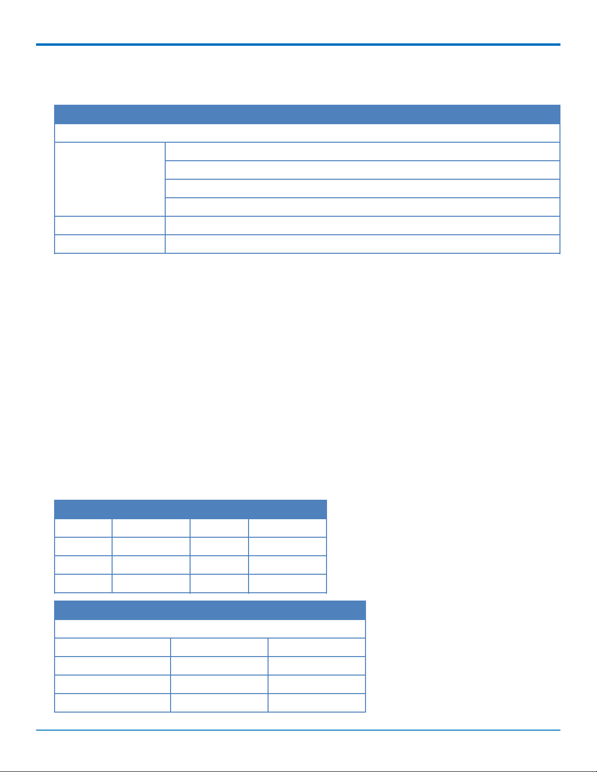
Documentation
The following documentation is available at multitech.com/support.
Document Description Part Number
SocketModem Cell LTE CAT1
MTSMC-LSP3 Device Guide
Universal Developer Kit 2.0
Developer Guide
USB Driver Installation Guide Instructions for installing USB drivers on Linux and Windows
Telit LE920x4/LE910Cx Series
AT Commands Reference
Guide
This document. Provides overview, safety and regulatory
information, design considerations, schematics, and device
information.
Information for developing with the MTUDK2 Developer Kit.
Includes an overview, design considerations, schematics, and
installation and operation information.
Systems.
Lists AT Commands and parameters used to configure your
device.
S000703
S000610
S000616
80490ST10778A
Rev. 4
6 SocketModem®Cell MTSMC-LSP3 Device Guide
Product Build Options
Product Description Carrier/Region
MTSMC-LSP3 Embedded LTE Cat 1 serial modem with GNSS Sprint
MTSMC-LSP3-U Embedded LTE Cat 1 USB modem with GNSS Sprint
Developer Kits
PRODUCT OVERVIEW
MTUDK2-ST-Cell Developer Kit for SocketModem, and Dragonfly cellular
devices.
Note:
These units ship without network activation.
To connect them to the cellular network, you need a cellular account. For more information, refer to
Account Activation.
The complete product code may end in .Rx. For example, MTSMC-LSP3.Rx, where R is revision and x
is the revision number.
All builds can be ordered individually or in 50-packs. Add SP to the model number for a single pack.
All
SocketModem®Cell MTSMC-LSP3 Device Guide 7
MECHANICAL DRAWINGS
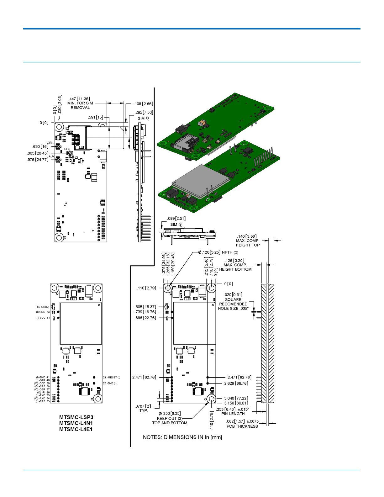
Chapter 2 – Mechanical Drawings
MTSMC-LSP3
8 SocketModem®Cell MTSMC-LSP3 Device Guide
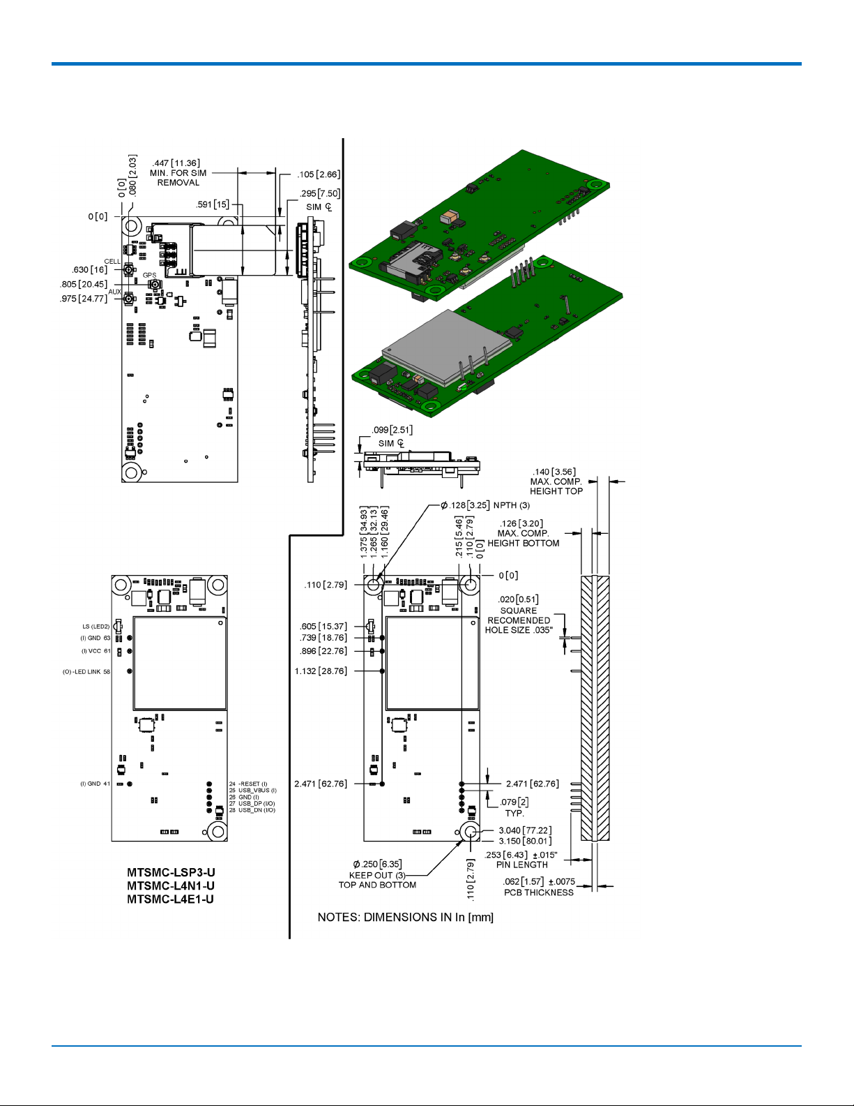
MTSMC-LSP3-U
MECHANICAL DRAWINGS
SocketModem®Cell MTSMC-LSP3 Device Guide 9

SPECIFICATIONS
Chapter 3 – Specifications
MTSMC-LSP3 and MTSMC-LSP3-U Specifications
Category Description
General
Standards LTE FDD Cat 1, 3GPP release 10 compliant
USB Interface is CDC-ACM compliant
TCP/IP Functions FTP, TCP, UDP, SMTP stack, IPv4/IPv6 stack
Frequency Bands 4G: 1900 (B2/B25) / AWS 1700 (B4) / 850 (B5/B26) / B12 (700)
Speed
Data Speed LTE: 10 Mbps downlink/ 5 Mbps uplink
Interface
USB Interface USB 2.0 HS/HSIC
Serial Modem Interface Up to 921.6 Kbps
Physical Description
Weight 0.4 oz. (10 g)
Dimensions Refer to Mechanical Drawing for Dimensions.
Connectors
Antenna Connector 2 surface mount UFL connectors for cellular, Rx diversity/MIMO
SIM 1.8V and 3V SIM holder for mini-SIM card
Environment
Operating Temperature -40° C to +85° C
Humidity 20%-90% RH, non-condensing
Power Requirements
Input Voltage 3.3-5 VDC
SMS
SMS Point-to-Point messaging
Mobile-Terminated SMS
Mobile-Originated SMS
10 SocketModem®Cell MTSMC-LSP3 Device Guide
Category Description
Certifications and Compliance
SPECIFICATIONS
EMC and Radio
Compliance
Safety Compliance UL 60950-1 2nd ED
Carrier Sprint
FCC Part 15 Class B
FCC Part 22
FCC Part 24
FCC Part 27
Powering Down Your Device
CAUTION: Failing to properly power down the device before removing power may corrupt your device's file
system.
To properly power down your device, use the following sequence or pull 3G_ONOFF signal low:
1. Issue the AT#SHDN command.
2. Wait 30 seconds.
3. Power off or disconnect power.
Note: If you send AT#SHDN and do not remove power AND the 3G_ONOFF line is high, the radio restarts after
60 seconds.
UART DC Electrical Characteristics
Units: Volts
Applies to the following pins:
Pin Signal Name Pin Signal Name
J33 -RTS J37 -DSR
J34 -RXD J38 -CTS
J35 -TXD J39 -DCD
J36 -RI J40 -DTR
Parameter Minimum Maximum
3.3 Volt Powered
Input Low Level 0 0.55
Input High Level 1.5 3.3
Output Low Level 0 0.55
Output High Level 2.35 3.3
SocketModem®Cell MTSMC-LSP3 Device Guide 11
SPECIFICATIONS
Parameter Minimum Maximum
5 Volt Powered
Input Low Level 0 0.8
Input High Level 2.3 5
Output Low Level 0 0.55
Output High Level 3.7 5
Absolute Maximum Rating
All models can run with an input voltage of either 3.3V or 5V. The maximum voltage on any signal pin equals the
input voltage.
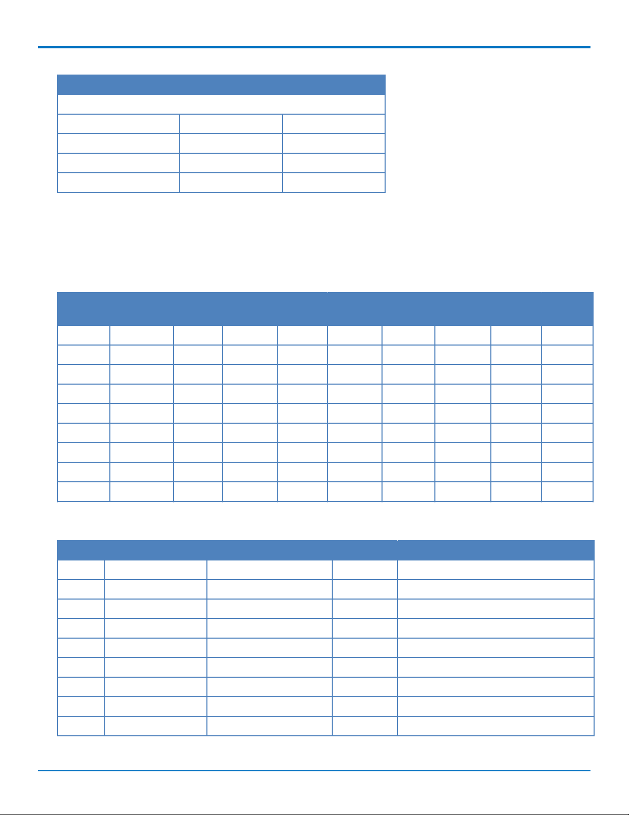
Electrical Characteristics Other Pins
Pin Signal
Name
J24 -RESET -- 0.8 2.0 -- -- -- -- --
J25 USB VBUS -0.3 0.8 2.0 8.7 -- -- -- --
J26 GND -- -- -- -- -- -- -- --
J27 USB DP -- 0.8 2 -- -- 0.3 2.8 --
J28 USB DN -- 0.8 2 -- -- 0.3 2.8 --
J41 GND -- -- -- -- -- -- -- --
J58 -LED LINK -- -- -- -- 0 0.45 2.85 3.3
J61 VCC -- -- -- -- -- -- -- --
J63 GND -- -- -- -- -- -- -- --
VIL Min VIL Max VIH Min VIH Max VOL Min VOL Max VOH Min VOH Max
Pinout Specifications
Pin Signal Name Logic Level Voltage
J24 –RESET 3.3 – 5.0 I Device reset (active low)
J25 USB VBUS 3.3 – 5.0 I USB power supply input
1
In/Out Description
J26 GND GND GND Ground
J27 USB DP 3.3 I/O USB data
J28 USB DN 3.3 I/O USB data
J33 –RTS 5.0 I Request to send (active low)
J34 –RXD 5.0 O Received data (active low)
J35 –TXD 5.0 I Transmitted data (active low)
J36 –RI 5.0 O Ring indicator (active low)
12 SocketModem®Cell MTSMC-LSP3 Device Guide
 Loading...