

Multi-Tech SocketModem MTSMC-G-F1, SocketModem MTSMC-G-F2 Developer's Manual
SocketModem™ GSM/GPRS
Embedded Data/Fax Wireless Modem
MTSMC-G-F1 – Global GSM/GPRS Class 10, 900/1800 MHz
MTSMC-G-F2 – Global GSM/GPRS Class 10, 850/1900 MHz
Developer’s Guide

Global SocketModem GSM/GPRS Developer’s Guide
MTSMC-G-F1 – GSM/GPRS Class 10, 900/1800 MHz
MTSMC-G-F2 – GSM/GPRS Class 10, 850/1900 MHz
PN S000297A, Version A
Copyright
This publication may not be reproduced, in whole or in part, without prior expressed written permission
from Multi-Tech Systems, Inc. All rights reserved.
Copyright © 2003, by Multi-Tech Systems, Inc.
Multi-Tech Systems, Inc. makes no representations or warranties with respect to the contents hereof and
specifically disclaims any implied warranties of merchantability or fitness for any particular purpose.
Furthermore, Multi-Tech Systems, Inc. reserves the right to revise this publication and to make changes
from time to time in the content hereof without obligation of Multi-Tech Systems, Inc. to notify any person
or organization of such revisions or changes.
Revisions
Revision Level Date Description
A 06/09/03 Initial release.
Patents
This device covered by the following patent: 5,673,268
Trademarks
Multi-Tech Trademarks: SocketModem, Multi-Tech, and the Multi-Tech logo.
All other products and technologies are the trademarks or registered trademarks of their respective
holders.
World Headquarters
Multi-Tech Systems, Inc.
2205 Woodale Drive
Mounds View, Minnesota 55112
Phone: 763-785-3500 or 800-328-9717
Fax: 763-785-9874
Technical Support
Country By Email By Phone
France: support@multitech.fr (33) 1-64 61 09 81
India: support@multitechindia.com 91 (124) 6340778
U.K.: support@multitech.co.uk (44) 118 959 7774
U.S. and Canada: oemsales@multitech.com (800) 972-2439
Rest of the World: oemsales@multitech.com (763) 717-5863
Internet Address:
http://www.multitech.com

Table of Contents
Table of Contents
CHAPTER 1 – PRODUCT DESCRIPTION AND SPECIFICATIONS ..........................................................4
P
RODUCT DESCRIPTION ............................................................................................................................... 4
PPLICATIONS..............................................................................................................................................4
A
P
RODUCT FEATURES.................................................................................................................................... 5
EATURE DETAILS........................................................................................................................................5
F
EVELOPER’S KIT ........................................................................................................................................5
D
T
ECHNICAL SPECIFICATIONS.........................................................................................................................6
ELATED MANUALS......................................................................................................................................6
R
DDITIONAL INFORMATION ............................................................................................................................ 6
A
CHAPTER 2 – MECHANICAL SPECIFICATIONS ......................................................................................7
P
HYSICAL DIMENSIONS................................................................................................................................. 7
IN CONFIGURATIONS ..................................................................................................................................8
P
Pin Descriptions...................................................................................................................................... 8
CHAPTER 3 – ELECTRICAL CHARACTERISTICS ...................................................................................9
LECTRICAL CHARACTERISTICS .............................................................................................................. 9
I/O E
OWER CONSUMPTION................................................................................................................................. 9
P
SIM I
NTERFACE ELECTRICAL CHARACTERISTICS .........................................................................................10
ANDLING PRECAUTIONS ........................................................................................................................... 10
H
CHAPTER 4 – SOCKETMODEM INTERFACES....................................................................................... 11
F
LASHING LED .......................................................................................................................................... 11
SIM I
NTERFACE .........................................................................................................................................11
NTERFACE...........................................................................................................................................12
RF I
RF Connector .......................................................................................................................................12
RF Performances.................................................................................................................................. 12
Receiver Features ................................................................................................................................12
Transmitter Features ............................................................................................................................12
CHAPTER 5 – SOCKETMODEM TEST BOARD ......................................................................................13
ERIAL TEST/DEMO BOARD COMPONENTS .................................................................................................. 13
S
ERIAL TEST/DEMO BOARD BLOCK DIAGRAM.............................................................................................. 14
S
CHAPTER 6 – APPLICATION CONSIDERATIONS.................................................................................. 15
G
ENERAL GUIDELINES FOR THE USE OF THE SOCKETMODEM....................................................................... 15
Hardware and RF .................................................................................................................................15
The Antenna .........................................................................................................................................15
Soldering and Cleaning the SocketModem ..........................................................................................15
IRMWARE UPGRADE ................................................................................................................................. 15
F
NITIAL CONFIGURATION USING MOBILE PHONETOOLS................................................................................. 15
I
APPENDIX A – SAFETY PRECAUTIONS & REGULATORY STANDARDS COMPLIANCE.................. 16
S
AFETY PRECAUTIONS ...............................................................................................................................16
RF Safety.............................................................................................................................................. 16
General Safety...................................................................................................................................... 17
General Safety Standards .................................................................................................................... 18
RF Exposures .......................................................................................................................................18
Instructions to OEMs ............................................................................................................................18
R
EGULATORY STANDARDS COMPLIANCE ..................................................................................................... 19
GSM compliance ..................................................................................................................................19
APPENDIX B – SOURCES FOR PERIPHERAL DEVICES ...................................................................... 20
GSM A
APPENDIX C – AT COMMAND LIST ........................................................................................................ 21
NTENNA.......................................................................................................................................... 20
APPENDIX D – ACRONYMS AND ABBREVIATIONS .............................................................................25
INDEX .........................................................................................................................................................26
3
Chapter 1 – Product Description and Specifications
Chapter 1 – Product Description and
Specifications
Product Description
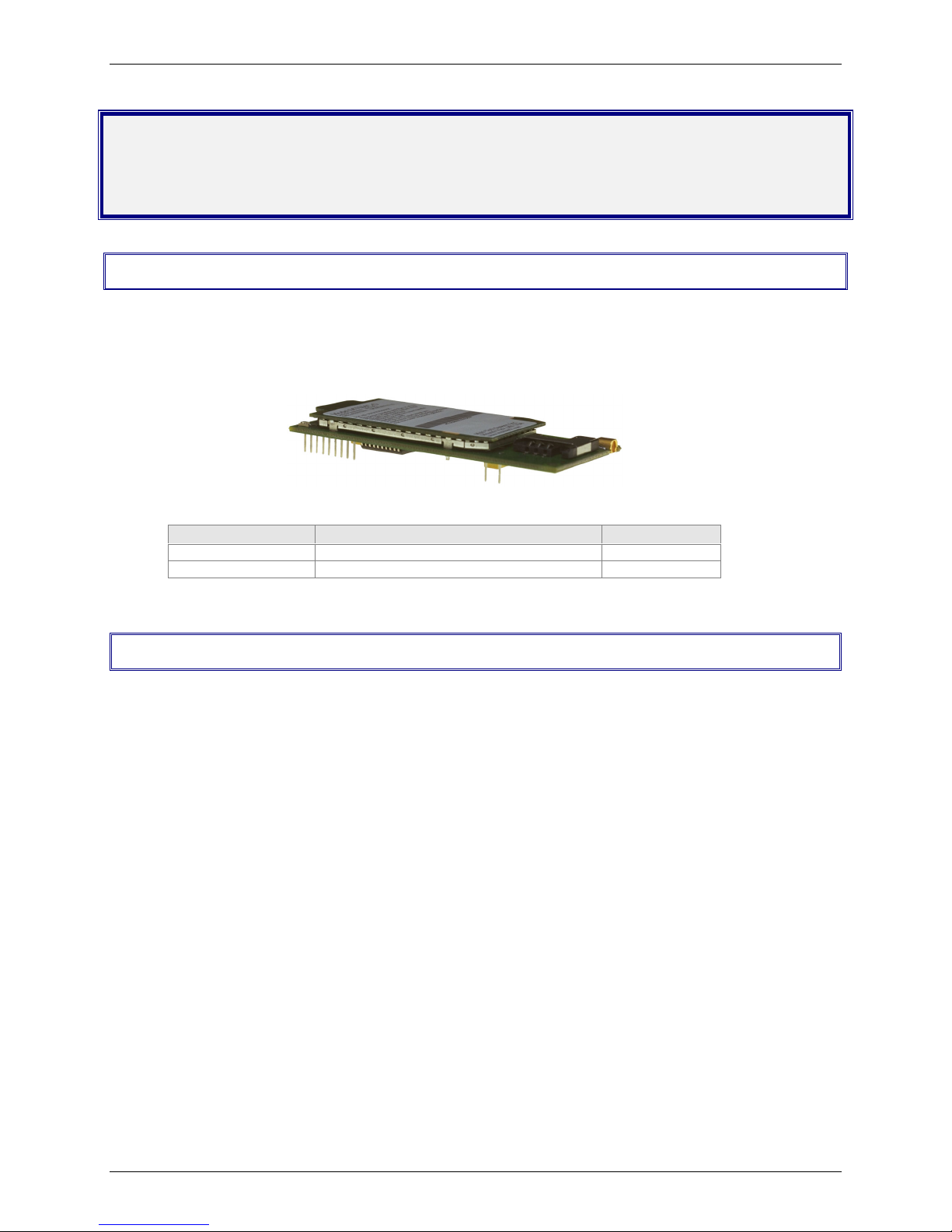
The Multi-Tech SocketModem GSM/GPRS is a complete, ready-to-integrate, embedded wireless modem.
Designed for global use, it offers standards-based multi-band GSM/GPRS Class 10. The SocketModem
GSM/GPRS is based on industry-standard open interfaces and utilizes the same form factor as the
SocketModem, SocketModem IP, or SocketEthernet IP modules from Multi-Tech.
Multi-Tech’s Wireless SocketModem GSM/GPRS
Product Description Region
MTSMC-G-F1 GMS/GPRS Class 10, 900/1800 MHz Global
MTSMC-G-F2 GMS/GPRS Class 10, 850/1900 MHz Global
Applications
The GSM/GPRS SocketModems are used to integrate wireless data and fax communications into
numerous embedded applications. They are targeted at applications that periodically need to send or
receive data over a wireless network and are ideal solutions for:
· Appliances
· ATM terminals
· Automotive
· Data collection
· Gas pumps
· Industrial and medical remote monitoring systems
· Remote diagnostics
· Remote metering
· Security systems
· Vending/gaming machines
· Other devices requiring wireless connectivity
4

Product Features
· GPRS Class 10
· Dual-band 850/1900 or 900/1800 GSM/GPRS
· GSM Class 1 and Class 2 Group 3 FAX
· Short Message Services features including text and PDU, point to point, cell broadcast
· 14.4K GSM circuit switched data
· MMCX antenna connector and SIM socket
· Serial interface supports DTE speeds to 115.2K
· AT command compatible*
· V.42bis data compression
· ME + SIM phone book management
· Fixed dialing number
· SIM Toolkit Class 2
· SIM, network and service provider locks
· Real time clock
· Alarm management
· UCS2 character set management
*AT Commands - AT commands for this product are published in a separate document available on the
Developer’s Kit system CD or from Multi-Tech. For a copy of this document, contact OEM Sales at
oemsales@multitech.com or call (800) 972-2439.
Chapter 1 – Product Description and Specifications
Feature Details
Integration Reduces Space, Power, and Cost – The SocketModem CDMA integrates the controller,
RF transceiver, and antenna interface in one module. This integration requires low power and low
real estate, and it provides an overall reduction in costs.
Reduces Development Time – The SocketModem GSM/GPRS can make your existing and next
generation device, machine, or system communication-ready without requiring significant hardware
changes to its design. This complete, ready-to-integrate wireless SocketModem allows you to
enhance your product while you focus on developing its core features.
Short Message Services – The SocketModem GSM/GPRS offers SMS features such as text and
PDU, point-to-point (MT/MO), and cell broadcast.
Management Features – The SocketModem GSM/GPRS provides advanced management features
that include: phone book management, fixed dialing number, real time clock, and alarm management.
Industry-standard Modem Commands – The SocketModem GSM/GPRS provides industry-
standard AT-style commands for ease of integration into your existing software application.
SocketModem Pin-Out – The SocketModem GSM/GPRS interfaces easily with existing products
through a standard serial communication channel. The complete on-board RF transceiver interfaces
with an antenna for direct connection to wireless SMS, circuit-switched dial-up, or packet data
networks. The SocketModem also includes an onboard LED to display network status. The
SocketModem is a Data Terminal Equipment (DTE) device with serial asynchronous protocol support.
The serial DTE channel is capable of transfer speeds to 115.2K bps and can be interfaced directly to
a UART or microcontroller.
Developer’s Kit
The SocketModem GSM/GPRS Developer’s Kit allows you to plug in the SocketModem and use it for
testing, programming, and evaluation. The kit includes:
· one development board with RS-232 DB-25 connector
· universal power supply
· antenna
· RS-232 cable
5

Chapter 1 – Product Description and Specifications
Technical Specifications
The SocketModem GSM/GPRS meets the following specifications:
Fax Compatibility
Weight
Dimensions
Power Requirements
Operating Environment
Storage Temperature
Certifications
Cleaning
GSM Class 1 and Class 2 Group 3 Fax
1 oz (26 g)
3.1” w x 1.4” h x 0.5” d
(8.0 cm x 3.5 cm x 1.2 cm)
5 VDC; 400mA Average, 2A Peak
-20° to +55° C
-30° to +85° C
CE Mark
EMC: FCC Part 2, 15, 22, 24, EN 55022 & EN55024
Safety: UL 60950, EN 60950
No cleaning/washing due to the manufacturing process used to
produce this product
Related Manuals
AT commands for this product are published in a separate document available on the Developer’s Kit
system CD or from Multi-Tech. Multi-Tech manuals and other resources are available on the Multi-Tech
Web page at http://www.multitech.com.
Additional Information
European Telecommunications Standards Institute (ETSI) - Contact the ETSI at:
650, route des Lucioles
06921 Sophia-Antipolis Cedex
France
Tel: +33 (0)4 92 94 42 00
Fax: +33 (0)4 93 65 47 16
http://www.etsi.org
Global Engineering Documents manages a collection of more than one million documents from over 460
organizations worldwide:
http://global.ihs.com
Phone: 800-854-7179
Fax: 303-792-2192
The ITU is the leading publisher of telecommunication technology, regulatory and standard information,
with over 4,000 titles in printed form, on CD-ROM and online at:
http://www.itu.int/publications/ .
6
Chapter 2 – Mechanical Specifications
Chapter 2 – Mechanical Specifications
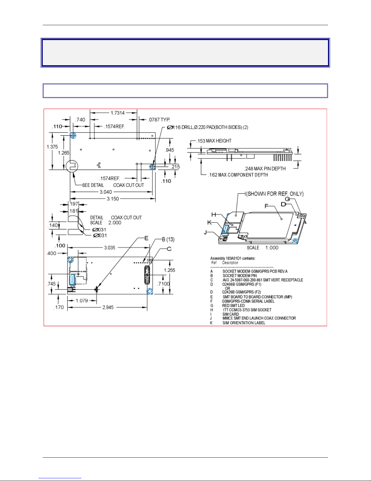
Physical Dimensions
SocketModem GSM/GPRS Mechanical Drawing
7
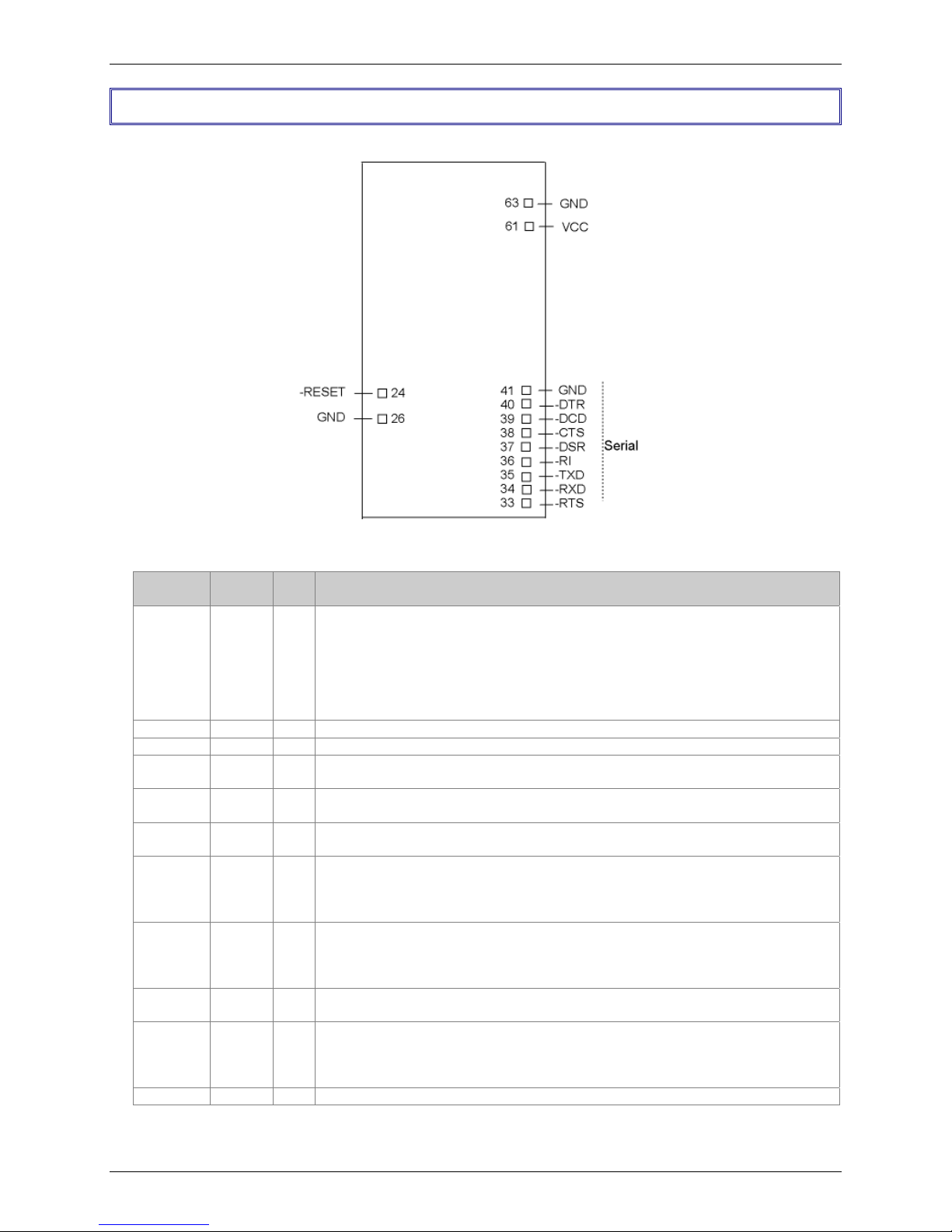
Pin Configurations
The SocketModem GSM/GPRS uses a 13-pin interface.
Chapter 2 – Mechanical Specifications
Pin Descriptions
Pin #
24 -RESET I/O
26, 41, 63 GND
33 –RTS I
34 –RXD O
35 –TXD I
36 –RI O
37 –DSR O
38 –CTS O
39 –DCD O
40 –DTR I
61 VCC PWR
Signal
Name
SocketModem Pins - Top View
I/O
Description
Type
Reset. This signal is used to force a reset procedure by providing low level during
at least 500µs. This signal is considered an emergency reset only. A reset
procedure is already driven by an internal hardware during the power-up
sequence.
This signal can also be used to provide a reset to an external device. It then acts
as an output. If no external reset is necessary, this input can be left open. If used
(emergency reset), it has to be driven by an open collector or an open drain.
Ground
Request to Send. The –RTS signal is used for hardware flow control.
Received Data. The modem uses the –RXD line to send received data to the
DTE and to send modem responses to the DTE.
Transmitted Data. The DTE uses the –TXD line to send data to the modem or to
transmit commands to the modem.
Ring Indicate. –RI output ON (low) indicates the presence of an ON segment of a
ring signal.
Data Set Ready. The –DSR indicates modem status to the DTE. –DSR OFF
(high) indicates that the DTE is to disregard all signals appearing on the
interchange circuits except Ring Indicator (–RI). It reflects the status of the local
data set and does not indicate an actual link with any remote data equipment.
Clear To Send. –CTS is controlled by the modem to indicate whether or not the
modem is ready to transmit data. –CTS ON, indicates to the DTE that signals
presented on TXD will be transmitted. –CTS OFF indicates to the DTE that it
should not transfer data across the interface on TXD.
Data Carrier Detect. –DCD output is ON (low) when a data connection is
established.
Data Terminal Ready (Active Low). The –DTR input is turned ON (low) by the
DTE when the DTE is ready to transmit or receive data. –DTR ON prepares the
modem to be connected, and, once connected, maintains the connection.
–DTR OFF places the modem in the disconnect state.
+5V
8
 Loading...