

Page 1

SocketModem EDGE
Embedded Wireless Modem
Preliminary Copy
Not for Release
Developer’s Guide
Page 2

Copyright and Technical Support
SocketModem EDGE Developer’s Guide
MTSMC-E
PN S000376A, Version A
Copyright
This publication may not be reproduced, in whole or in part, without prior expressed written permission from MultiTech Systems, Inc. All rights reserved.
Copyright © 2005, by Multi-Tech Systems, Inc.
Multi-Tech Systems, Inc. makes no representations or warranties with respect to the contents hereof and specifically
disclaims any implied warranties of merchantability or fitness for any particular purpose. Furthermore, Multi-Tech
Systems, Inc. reserves the right to revise this publication and to make changes from time to time in the content hereof
without obligation of Multi-Tech Systems, Inc. to notify any person or organization of such revisions or changes.
Revisions
Revision Level Date Description
A 06/28/05 Initial release.
Trademarks
Multi-Tech Trademarks: SocketModem, Multi-Tech, and the Multi-Tech logo.
All other products and technologies are the trademarks or registered trademarks of their respective holders.
World Headquarters
Multi-Tech Systems, Inc.
2205 Woodale Drive
Mounds View, Minnesota 55112
Phone: 763-785-3500 or 800-328-9717
Fax: 763-785-9874
Technical Support
Country By Email By Phone
France: support@multitech.fr (33) 1-64 61 09 81
India: support@multitechindia.com 91 (124) 6340778
U.K.: support@multitech.co.uk (44) 118 959 7774
U.S. and Canada: oemsales@multitech.com (800) 972-2439
Rest of the World: oemsales@multitech.com (763) 717-5863
Internet Address: http://www.multitech.com
Multi-Tech Systems, Inc. SocketModem EDGE Embedded Wireless Modem Developer’s Guide (S000376A) 2
Page 3

Table of Contents
Table of Contents
CHAPTER 1 – PRODUCT DESCRIPTION AND SPECIFICATIONS............................................................................ 4
PRODUCT DESCRIPTION................................................................................................................................................. 4
PRODUCT FEATURES .....................................................................................................................................................4
AT COMMANDS .............................................................................................................................................................4
FEATURE DETAILS ......................................................................................................................................................... 5
DEVELOPER’S KIT..........................................................................................................................................................5
TECHNICAL SPECIFICATIONS........................................................................................................................................... 5
SAFETY ........................................................................................................................................................................6
Instructions to OEMs...............................................................................................................................................6
Radio Frequency (RF) Safety .................................................................................................................................6
Electronic Devices ..................................................................................................................................................6
Vehicle Electronic Equipment .................................................................................................................................6
Medical Electronic Equipment................................................................................................................................. 6
Aircraft ....................................................................................................................................................................7
Handling Precautions..............................................................................................................................................7
Electromagnetic Interference (EMI) Considerations................................................................................................ 7
Driving.....................................................................................................................................................................7
Children ..................................................................................................................................................................7
Blasting Areas......................................................................................................................................................... 7
Potentially Explosive Atmospheres ......................................................................................................................... 8
MULTI-TECH’S COMPLIANCE WITH SAFETY STANDARDS .................................................................................................... 8
Radio Frequency Exposures...................................................................................................................................8
CHAPTER 2 – MECHANICAL SPECIFICATIONS........................................................................................................ 9
PHYSICAL DIMENSIONS ..................................................................................................................................................9
PIN CONFIGURATIONS..................................................................................................................................................10
EDGE Pin Descriptions.........................................................................................................................................10
Pin 58 – LED Mode...............................................................................................................................................11
LEDS AND SOCKETMODEM STATUS.............................................................................................................................. 11
CHAPTER 3 – ELECTRICAL CHARACTERISTICS ................................................................................................... 12
I/O ELECTRICAL CHARACTERISTICS...............................................................................................................................12
VOICE MODE POWER CONSUMPTION ............................................................................................................................ 12
DATA MODE POWER CONSUMPTION.............................................................................................................................. 12
SIM INTERFACE ELECTRICAL CHARACTERISTICS ............................................................................................................13
CHAPTER 4 – SIM CONNECTOR AND ANTENNA CONNECTOR ...........................................................................14
SIM CONNECTOR........................................................................................................................................................ 14
ANTENNA....................................................................................................................................................................14
Receiver Features.................................................................................................................................................14
Transmitter Features............................................................................................................................................. 14
CHAPTER 5 – SOCKETMODEM SCHEMATICS........................................................................................................16
SOCKETMODEM EDGE DIAGRAMS................................................................................................................................. 16
SOCKETMODEM EDGE BLOCK DIAGRAM ......................................................................................................................17
SOCKETMODEM EDGE SCHEMATICS............................................................................................................................ 18
CHAPTER 6 – HARDWARE GUIDELINES................................................................................................................. 20
GENERAL GUIDELINES FOR THE USE OF THE SOCKETMODEM ..........................................................................................20
Hardware and RF.................................................................................................................................................. 20
The Antenna .........................................................................................................................................................20
Soldering and Cleaning the SocketModem...........................................................................................................20
APPENDIX A – WARRANTY AND REPAIRS.............................................................................................................21
Multi-Tech Warranty Statement ............................................................................................................................21
Repair Procedures for U.S. and Canadian Customers .........................................................................................21
Repair Procedures for International Customers (Outside U.S.A. and Canada).....................................................22
Repair Procedures for International Distributors ...................................................................................................22
INDEX .......................................................................................................................................................................... 23
Multi-Tech Systems, Inc. SocketModem EDGE Embedded Wireless Modem Developer’s Guide (S000376A) 3
Page 4

Chapter 1 – Product Description and Specifications
Chapter 1 – Product Description and
Specifications
Product Description
The Multi-Tech SocketModem EDGE embedded wireless modem delivers some of the fastest cellular data speeds by
utilizing EDGE technology. It allows users to connect to the Internet and send and receive data up to three times
faster than possible with an ordinary GSM/GPRS network making it ideal for highly data-intensive applications. Based
on industry-standard open interfaces, the SocketModem EDGE wireless modem is equipped with quad-band GSM,
which means it can be used worldwide on all exitsting GSM networks. In addition, it utilizes Multi-Tech's universal
socket design.
Multi-Tech’s SocketModem EDGE Embedded Wireless Modem Builds
Product Trade Name Description Region
MTSMC-E
MTSMC-E-V
SocketModem
SocketModem
Product Features
• EDGE (E-GPRS) Class 10
• GPRS Class 12
• Quad-band GSM 850/900/1800/1900 MHz
• Packet data rates up to 240K bps (coding scheme, MCS-9, LLC layer, 4 time slots)
• Embedded TCP/IP stack supports TCP, UDP, DNS, FTP, SMTP, POP3, HTTP
• Circuit-switched data up to 9600 bps transparent and non-transparent
• Supports Short Message Service features including text and PDU mode, point to point (MT/MO), and
cell broadcast
• SMA antenna connector
• Serial interface supporting DTE speeds to 460K bps
• AT command compatible*
• Carrier approved
• Voice features include Half Rate (HR), Full Rate (FR), Enhanced Full Rate (EFR), Adaptive Multi Rate
(AMR), as well as hands free echo cancellation, and noise reduction
• Two-year warranty
AT Commands
AT commands for this product are published in a separate document available on the Developer’s Kit system CD or
from Multi-Tech. For a copy of this document, contact OEM Sales at oemsales@multitech.com
(800) 972-2439.
EDGE
EDGE
Quad-band EDGE Class 10 Global
Quad-band EDGE Class 10 w/Voice Global
or call:
Multi-Tech Systems, Inc. SocketModem EDGE Embedded Wireless Modem Developer’s Guide (S000376A) 4
Page 5

Chapter 1 – Product Description and Specifications
Feature Details
Applications. With packet data speeds up to three times faster than ordinary CPRS modems, the SocketModem
EDGE wireless modem is targeted at highly data-intensive applications such as remote video surveillance and
other multimedia applications that send digital images, Web pages, and photographs.
Integration Reduces Space, Power, and Cost. The SocketModem
controller, RF transceiver, and antenna interface in one module. This integration requires low power and low real
estate, and provides an overall reduction in costs.
Reduces Development Time. The SocketModem EDGE wireless modem enhances your product while you
focus on developing its core features. It actually provides faster time-to-market because it relieves the burden
and expense of obtaining PTCRB and RF approvals.
Internet-Enabled. The SocketModem EDGE wireless modem includes and embedded TCP/IP stack to bring
Internet connectivity to any device without making changes to its hardware design. Using the Internet protocols
and the wireless connection to an IP network, it sends and receives data over the Internet.
SocketModem EDGE Pin-Out. The SocketModem EDGE wireless modem interfaces easily with existing
products through a standard serial communication channel. The serial DTE channel is capable of transfer
speeds of 460K bps and can be interfaced directly to an UART or microcontroller. The complete on-board RF
transceiver interfaces with an antenna for direct connection to wireless SMS, circuit-switched dial-up, or packet
data networks. It also includes an onboard LED to display network status.
Universal Socket Connectivity. Multi-Tech's Universal Socket flexible comm-port architecture provides analog
dial-up, ISDN, wireless, or Ethernet socket connectivity with interchangeable modules. This allows you to utilize
one system design and populate it with your communication module of choice. In addition, you are assured a
seamless migration to future technologies.
EDGE wireless modem integrates the
Developer’s Kit
The Developer’s Kit allows you to plug in the module and use it for testing, programming, and evaluation. The kit
includes:
• one development board with RS-232 DB-25 connector
• universal power supply
• antenna
• RS-232 cable
Technical Specifications
The SocketModem EDGE wireless modem meets the following specifications:
Packet Data
Circuit-Switched Data
Fax
SMS
Connectors
IP Protocols Supported
Power Requirements
Operating Environment
Physical Description
Certifications
Warranty
EDGE: E-GPRS Class 10, Modulation & coding scheme MCS 1-9, Mobile station Class B
GPRS: GPRS Class 12, full PBCCH support, coding scheme 1-4, Mobile station Class B
Asynchronous, transparent & non-transparent up to 9600 bps
Class 1 Group 3 Fax
Text & PDU, Point-to-Point, cell broadcast
Antenna: MMCX
SIM: Standard 3V SIM receptacle
TCP, UDP, DNS, FTP, SMTP, POP3, HTTP
5 VDC to 32 VDC; 400mA typical
-30° to +50° C
Dimensions: 2.55” L x 1.4” W x 0.5” H (6.48 cm x 3.5 cm x .87 cm)
Weight: 1 oz. (20 g)
CE Mark
EMC: FCC Part 2, 15, 22, 24, EN 55022 & EN55024
Safety: cUL, UL 60950, EN 60950
Network: PTCRB
2 years
Multi-Tech Systems, Inc. SocketModem EDGE Embedded Wireless Modem Developer’s Guide (S000376A) 5
Page 6

Chapter 1 – Product Description and Specifications
Safety
Instructions to OEMs
The Multi-Tech product manual includes specific warnings and cautions in order to ensure that OEMs are aware
of their responsibilities, with regards to RF exposure compliance, for products into which the modem is
integrated. With this guidance, the OEM will be able to incorporate into their documentation the necessary
operating conditions and warnings.
OEMs need to provide a manual with the ‘’final’’ product that clearly states the operating requirements and
conditions and that these must be observed to ensure compliance with current FCC RF exposure requirements /
MPE limits (see the “RF Exposures” section below). This will enable the OEM to generate (and provide the enduser with) the appropriate operating instructions, warnings and cautions, and/or markings for their product.
IMPORTANT!
FOR THE EFFICIENT AND SAFE OPERATION OF YOUR E-GPRS
INTEGRATED MODEM, READ THIS INFORMATION BEFORE USE.
Radio Frequency (RF) Safety
General
Your SocketModem is based on the EGPRS standard for cellular technology. The standard is spread all
over the world. It covers Europe, Asia, and some parts of America and Africa. This is the most used
telecommunication standard. Your modem is actually a low power radio transmitter and receiver. It
sends out and receives radio frequency energy. When you use your SocketModem integrated modem,
the cellular system, which handles your calls controls both the radio frequency and the power level of
your cellular modem.
Exposure to RF Energy
There has been some public concern about possible health effects of using GSM modems. Although
research on health effects from RF energy has focused on the current RF technology for many years,
scientists have begun research regarding newer radio technologies, such as GSM. After existing
research had been reviewed, and after compliance to all applicable safety standards had been tested, it
has been concluded that the product was fitted for use. If you are concerned about exposure to RF
energy there are things you can do to minimize exposure. Obviously, limiting the duration of your calls
will reduce your exposure to RF energy. In addition, you can reduce RF exposure by operating your
cellular modem efficiently by following the below guidelines.
Efficient Modem Operation
For your modem to operate at the lowest power level, consistent with satisfactory call quality:
• If your modem has an extendible antenna, extend it fully. Some models allow you to place a call with
the antenna retracted. However your modem operates more efficiently with the antenna fully
extended.
• Do not hold the antenna when the modem is IN USE. Holding the antenna affects call quality and
may cause the modem to operate at a higher power level than needed.
Antenna Care and Replacement
Do not use the modem with a damaged antenna. If a damaged antenna comes into contact with the
skin, a minor burn may result. Replace a damaged antenna immediately. Consult your manual to see if
you may change the antenna yourself. If so, use only a manufacturer-approved antenna. Otherwise,
have your antenna repaired by a qualified technician. Use only the supplied or approved antenna.
Unauthorized antennas, modifications, or attachments could damage the modem and may contravene
local RF emission regulations or invalidate type approval.
Electronic Devices
Most electronic equipment, for example in hospitals and motor vehicles, is shielded from RF energy.
However, RF energy may affect some improperly shielded electronic equipment.
Vehicle Electronic Equipment
Check your vehicle manufacturer representative to determine if any on-board electronic equipment is
adequately shielded from RF energy.
Medical Electronic Equipment
Consult the manufacturer of any personal medical devices (such as pacemakers, hearing aids, etc.) to
determine if they are adequately shielded from external RF energy. Turn your modem OFF in health care
facilities when any regulations posted in the area instruct you to do so. Hospitals or health care facilities may
be using RF monitoring equipment.
Multi-Tech Systems, Inc. SocketModem EDGE Embedded Wireless Modem Developer’s Guide (S000376A) 6
Page 7

Chapter 1 – Product Description and Specifications
Aircraft
Turn your modem OFF before boarding any aircraft.
• Use it on the ground only with crew permission.
• Do not use it in the air.
To prevent possible interference with aircraft systems, Federal Aviation Administration (FAA) regulations
require you to have permission from a crew member to use your modem while the aircraft is on the ground.
To prevent interference with cellular systems, local RF regulations prohibit using your modem while
airborne.
Handling Precautions
All devices must be handled with certain precautions to avoid damage due to the accumulation of static
charge. Although input protection circuitry has been incorporated into the devices to minimize the effect of
this static buildup, proper precautions should be taken to avoid exposure to electrostatic discharge during
handling and mounting.
Electromagnetic Interference (EMI) Considerations
The following guidelines are offered to specifically help minimize EMI generation. Some of these guidelines
are the same as, or similar to, the general guidelines but are mentioned again to reinforce their importance.
In order to minimize the contribution of the SocketModem-based design to EMI, the designer must
understand the major sources of EMI and how to reduce them to acceptable levels.
1. Keep traces carrying high frequency signals as short as possible.
2. Provide a good ground plane or grid. In some cases, a multilayer board may be required with full layers
for ground and power distribution.
3. Decouple power from ground with decoupling capacitors as close to the SocketModem module power
pins as possible.
4. Eliminate ground loops, which are unexpected current return paths to the power source and ground.
5. Decouple the telephone line cables at the telephone line jacks. Typically, use a combination of series
inductors, common mode chokes, and shunt capacitors. Methods to decouple telephone lines are
similar to decoupling power lines; however, telephone line decoupling may be more difficult and
deserves additional attention. A commonly used design aid is to place footprints for these components
and populate as necessary during performance/EMI testing and certification.
6. Decouple the power cord at the power cord interface with decoupling capacitors. Methods to decouple
power lines are similar to decoupling telephone lines.
7. Locate high frequency circuits in a separate area to minimize capacitive coupling to other circuits.
8. Locate cables and connectors so as to avoid coupling from high frequency circuits.
9. Lay out the highest frequency signal traces next to the ground grid.
10. If a multilayer board design is used, make no cuts in the ground or power planes and be sure the
ground plane covers all traces.
11. Minimize the number of through-hole connections on traces carrying high frequency signals.
12. Avoid right angle turns on high frequency traces. Forty-five degree corners are good; however, radius
turns are better.
13. On 2-layer boards with no ground grid, provide a shadow ground trace on the opposite side of the board
to traces carrying high frequency signals. This will be effective as a high frequency ground return if it is
three times the width of the signal traces.
14. Distribute high frequency signals continuously on a single trace rather than several traces radiating from
one point.
Driving
Check the laws and the regulations regarding the use of cellular devices in the area where you have to drive
as you must comply with these laws and regulations. When using your modem while driving, please give full
attention to driving. Pull off the road and park before making or answering a call if driving conditions so
require.
Children
Do not allow children to play with your modem. It is not a toy. Children could hurt themselves or others (by
poking themselves or others in the eye with the antenna, for example). Children could damage the modem
or make calls that increase your modem bills.
Blasting Areas
To avoid interfering with blasting operations, turn your unit OFF when in a “blasting area” or in areas posted
“turn off two-way radio”. Construction crews often use remote control RF devices to set off explosives.
Multi-Tech Systems, Inc. SocketModem EDGE Embedded Wireless Modem Developer’s Guide (S000376A) 7
Page 8

Chapter 1 – Product Description and Specifications
Potentially Explosive Atmospheres
Turn your modem OFF when in any area with a potentially explosive atmosphere. It is rare, but your modem
or its accessories could generate sparks. Sparks in such areas could cause an explosion or fire resulting in
bodily injuries or even death. Areas with a potentially explosive atmosphere are often, but not always, clearly
marked. They include fueling areas such as gas stations; below deck on boats; fuel or chemical transfer or
storage facilities; and areas where the air contains chemicals or particles, such as grain, dust, or metal
powders. Do not transport or store flammable gas, liquid, or explosives, in the compartment of your vehicle,
which contains your modem or accessories. Before using your modem in a vehicle powered by liquefied
petroleum gas (such as propane or butane) ensure that the vehicle complies with the relevant fire and safety
regulations of the country in which the vehicle is to be used.
Multi-Tech’s Compliance with Safety Standards
THIS WIRELESS SOCKETMODEM COMPLIES WITH ALL APPLICABLE RF SAFETY STANDARDS. This
cellular modem meets the standards and recommendations for the protection of public exposure to RF
electromagnetic energy that have been established by governmental bodies and other qualified
organizations, such as the following:
• Directives of the European Community,
• Directorate General V in Matters of Radio Frequency Electromagnetic Energy
Radio Frequency Exposures
Pursuant to 47 CFR § 24.52 of the FCC Rules and Regulations, personal communications services (PCS)
equipment is subject to the radio frequency radiation exposure requirements specified in § 1.1307(b), §
2.1091 and § 2.1093 as appropriate.
The Multi-Tech SocketModem is a GSM (cellular 850/PCS 1900) terminal which operates in the US licensed
PCS frequency spectrum. The device transmits over the 1850-1910 MHz or 824-849 MHz bands and
receives over the 1930-1990 MHz or 869-894 MHz bands. Multi-Tech Systems, Inc. certifies that it has
determined that the Modem complies with the RF hazard requirements applicable to broadband PCS
equipment operating under the authority of 47 CFR Part 24, Subpart E of the FCC Rules and Regulations.
This determination is dependent upon installation, operation, and use of the equipment in accordance with
all instructions provided.
The modem is designed for and intended to be used in fixed and mobile applications. "Fixed" means that the
device is physically secured at one location and is not able to be easily moved to another location. "Mobile"
means that the device is designed to be used in other than fixed locations and generally in such a way that a
separation distance of at least 20 cm is normally maintained between the transmitter's antenna and the body
of the user or nearby persons. The Modem is not designed for or intended to be used in portable
applications (within 20 cm of the body of the user) and such uses are strictly prohibited. To ensure that the
unit complies with current FCC regulations limiting both maximum RF output power and human exposure to
radio frequency radiation, a separation distance of at least 20 cm must be maintained between the unit's
antenna and the body of the user and any nearby persons at all times and in all applications and uses.
Additionally, in mobile applications, maximum antenna gain must not exceed 2.6 dBi for mobile
applications and 3.5 dBi for fixed applications in the 850 MHz band to comply with 24.232(b) and is limited to
Multi-Tech Systems, Inc. SocketModem EDGE Embedded Wireless Modem Developer’s Guide (S000376A) 8
Page 9

Chapter 2 – Mechanical
Specifications
Physical Dimensions
Chapter 2 – Mechanical Specifications
SocketModem EDGE Wireless Modem Mechanical Drawing
Multi-Tech Systems, Inc. SocketModem EDGE Embedded Wireless Modem Developer’s Guide (S000376A) 9
Page 10

Pin Configurations
Chapter 2 – Mechanical Specifications
Universal Socket Pins
EDGE Pin Descriptions
Signal
Pin #
Name
9 Dummy
22 MIC+ I
23 MIC– O
24 –Reset I
26 GND GND
33 –RTS I The –RTS signal is used for hardware flow control.
34 –RXD O
35 –DSR O
36 –RI /
3.3V
I/O
Description
Type
Dummy
Wireless
Wireless
Device Reset (with pull-up).
The active low –RESET input resets the device logic and returns the configuration of
the device to the original factory default values of "stored values" in the NVRAM.
–RESET is tied to VCC through a time-constant circuit for “Power-on-Reset”
functionality. The module is ready to accept commands after a fixed amount of time
after power-on or reset.
Ground
Data Set Ready. The –DSR indicates modem status to the DTE. –DSR OFF (high)
indicates that the DTE is to disregard all signals appearing on the interchange circuits
except Ring Indicator (–RI). It reflects the status of the local data set and does not
indicate an actual link with any remote data equipment.
Clear To Send. –CTS is controlled by the modem to indicate whether or not the
modem is ready to transmit data. –CTS ON, indicates to the DTE that signals
presented on TXD will be transmitted. –CTS OFF indicates to the DTE that it should
not transfer data across the interface on TXD.
RING (Active Low). Incoming ring signal from phone.
O
Ring Indicate. –RI output ON (low) indicates the presence of an ON segment of a
ring signal on the telephone line. The modem will not go off-hook when –RI is active;
the modem waits for –RI to go inactive before going off-hook.
Multi-Tech Systems, Inc. SocketModem EDGE Embedded Wireless Modem Developer’s Guide (S000376A) 10
Page 11

Chapter 2 – Mechanical Specifications
Pin # Signal
Name
38 –CTS O
39 –DCD O
40 –DTR
41 GND GND
42 SPK– O/O
43 SPK+ O/I
58 LED
LINK
61 VCC PWR
63 GND GND
I/O
Description
Type
Clear to Send (Active Low). –CTS is controlled by the module to indicate whether or
not the module is ready to transmit data. –CTS ON indicates to the DTE that signals
on TXD will be transmitted. –CTS OFF indicates to the DTE that it should not transfer
data on TXD.
Data Carrier Detect (Active Low). –DCD output is ON (low) when a data
connection is established and the module is ready to send/receive data.
Data Terminal Ready (Active Low). The –DTR input is turned ON (low) when the
DTE is ready to communicate. –DTR ON prepares the modem to be connected, and,
once connected, maintains the connection. –DTR OFF places the modem in the
I
disconnect state under control of the &Dn and &Qn commands.
Note: When the –DTR pin is not in use, it should be tied low.
Ground
Wireless
Wireless
LED LINK (Active Low). LED Output. During normal operation, this pin lights the
O
LINK LED to indicate a good link is detected. See LED Mode Table below.
DC Input Power. 3.3 V or 5 V DC power, depending upon the build.
Ground
Pin 58 – LED Mode
LED Mode – Pin 58 Operating Status
Off SCME is off or run in SLEEP, Alarm, or Charge-
only mode.
600 ms ON / 600ms OFF No SIM card inserted or no PIN entered, or
netowrk search in progress, or ongoing user
authentication, or network login in progress.
75 ms ON / 75 ms OFF / 75 ms ON
3 s OFF
Flashing
ON Depending on type of call:
One or more GPRS contexts activated.
Indicates GPRS data transfer: When a GPRS
transfer is in progress, the LED goes on within 1
second after data packets were exchanged. Flash
duration is approximately 0.5 s.
Voice Call: Connected to remote party.
Data Call: Connected to remote party or
exchange of parameters while
setting up or disconnecting a call.
LEDs and SocketModem Status
The flashing LED signal is used to indicate the working mode of the SocketModem.
Signal SocketModem Status
OFF Download mode or switched OFF>
Continuously lit Switched ON (not registered on the network) ON
Flashing Switched ON (registered on the network)
Multi-Tech Systems, Inc. SocketModem EDGE Embedded Wireless Modem Developer’s Guide (S000376A) 11
Page 12
Chapter 3 – Electrical Characteristics
Chapter 3 – Electrical Characteristics
Electrical characteristics for the 5V Serial SocketModem are presented in this chapter.
I/O Electrical Characteristics
5 Vdc Characteristics (TA = -20° C to 55° C; VDD = 5 V ± 0.25 V) VDDMAX = 5.25 V
Digital Inputs
–DTR (40), –TXD (35), –RTS (33), –RESET (24)
Digital Outputs
–DCD (39), –CTS (38), –DSR (37), –RI (36), –RXD (34)
Digital Input Capacitance
Voice Mode Power Consumption
GSM Call Power Consumption in EGSM900 and GSM850 @25 degrees C
+5V
+5V
+5V
+5V
GSM Call Power Consumption in GSM1800 & 1900 MHz @25 degrees C
+5V
+5V
+5V
+5V
Conditions I
During TX bursts @2W 1.2 A 1.3 A
Average @ 2W 250 mA 320 mA
Average @ ).5W 180 mA 200 mA
Average idle mode 15 mA 25 mA
Conditions I
During TX bursts @1W 1.1 A 1.2 A
Average @1W 210 mA 235 mA
Average @ 0.25W 165 mA 185 mA
Average idle mode 15 mA 25 mA
NOM
NOM
Input High
Min 3.675 V
Output High
Min. 4 V
I
I
Input Low
Max .7 V
Output Low
Max 0.4 V
MAX
MAX
Current Drive:
2 ma
5 PF
Data Mode Power Consumption
GPRS Class 10 Power Consumption in EGSM/GPRS 900 MHz and GSM/GRPS 850 MHz Mode
+5V
+5V
+5V
+5V
Conditions I
During TX bursts @ 2W 1.2 A 1.3 A
Average @ 2W 420 mA 470 mA
Average @ 0.5W 280 mA 320 mA
Average idle mode 15 mA 25 mA
GPRS Class 10 Power Consumption in GSM/GRPS 1800 MHz and GSM/GRPS 1900 MHz
+5V
+5V
+5V
+5V
Conditions I
During TX bursts @ 1W 1.1 A peak 1.2 A peak
Average @ 1W 350 mA 400 mA
Average @ .25W 180 mA 210 mA
Average idle mode 15 mA 25 mA
EGPRS Class 10 Power Consumption in EGRPS 1800 MHz and EGRPS 1900 MHz
+5V
+5V
+5V
+5V
Conditions I
During TX bursts @ 5W 1.4 A peak 1.6 A peak
Average @ .5W 430 mA 525 mA
Average @ .25W 375 mA 450 mA
Average idle mode 15 mA 25 mA
I
NOM
I
NOM
I
NOM
MAX
MAX
MAX
Multi-Tech Systems, Inc. SocketModem EDGE Embedded Wireless Modem Developer’s Guide (S000376A) 12
Page 13

Chapter 3 – Electrical Characteristics
SIM Interface Electrical Characteristics
SIM Interface Electrical Characteristics
This information is repeated in the next chapter under the SIM Interface section.
Parameter Conditions Min Typ Max Unit
SIMDATA VIH
SIMDATA VIL I
SIMRST,
SIMDATA
SIMCLK V
OH
SIMRST,
SIMDATA
I
= +/- 20µA
IH
= 1 mA 0.3xSIMVCC V
IL
Source current
= 20µA
Sink current
= -200µA
SIMCLK VOL
SIMVCC Output Voltage I
SIMCLK
<= 6mA 2.70 2.80 2.85 V
SIMVCC
Loaded with 30pF 50 ns
Rise/Fall Time
SIMRST,
Loaded with 30pF 1
SIMDATA
Rise/Fall Time
SIMCLK
Loaded with 30pF 3.25 MHz
Frequency
0.7xSIMVCC V
SIMVCC – 0.1V V
0.1
µs
Multi-Tech Systems, Inc. SocketModem EDGE Embedded Wireless Modem Developer’s Guide (S000376A) 13
Page 14

Chapter 4 - SocketModem Interfaces
Chapter 4 – SIM Connector and
Antenna Connector
This chapter describes the SocketModem SIM connector and the antenna and its connector.
SIM Connector
The internal SIM interface of the SocketModem supports the standard 3V SIM only.
Antenna
The integrated modem antenna connector is a MMCX connector. The MMCX connector incorporates a 'Snap On'
latching action in order to make the connection easier with an excellent RF performance. An additional advantage is
its small physical size, which is 50% of the standard MCX connector.
This type of connector is suitable for the standard ranges of flexible and semi-rigid cables. The characteristic
impedance of the MMCX coaxial connector is 50 ohm. The antenna manufacturer must guarantee that the antenna
will be working according to the radio characteristics presented in the table below.
RF performances are compliant with the ETSI recommendation 05.05 and 11.10.
The main parameters are:
Receiver Features
• EGSM Sensitivity : < -104 dBm
• GSM 1800/GSM 1900 Sensitivity : < -102 dBm
• Selectivity @ 200 kHz : > +9 dBc
• Selectivity @ 400 kHz : > +41 dBc
• Dynamic range : 62 dB
• Intermodulation : > -43 dBm
• Co-channel rejection : + 9 dBc
Transmitter Features
• Maximum output power (EGSM) : 33 dBm +/- 2 dB
• Maximum output power (DCS/PCS) : 30 dBm +/- 2 dB
• Minimum output power (EGSM): 5 dBm +/- 5 dB
• Minimum output power (DCS/PCS): 0 dBm +/- 5 dB
• H2 level : < -30 dBm
• H3 level : < -30 dBm
• Noise in 925 - 935 MHz : < -67 dBm
• Noise in 935 - 960 MHz : < -79 dBm
• Noise in 1805 - 1880 MHz : < -71 dBm
• Phase error at peak power : < 5 ° RMS
• Frequency error : +/- 0.1 ppm max
Radio Characteristics
Frequency RX
Frequency TX
RF Power Stand
Impedance 50 ohms
VSWR <2
Typical Radiated Gain 0 dBi on azimuth plane
GSM 850 EGSM 900 GSM 1800 GSM 1900
869 to 894 MHz 925 to 960 MHz 1805 to 1880 MHz 1930 to 1990 MHz
824 to 849 MHz 880 to 915 MHz 1710 to 1785 MHz 1850 to 1910 MHz
2W at 12.5% duty
cycle
2W at 12.5% duty
cycle
1W at 12.5% duty
cycle
1W at 12.5% duty cycle
Multi-Tech Systems, Inc. SocketModem EDGE Embedded Wireless Modem Developer’s Guide (S000376A) 14
Page 15
Chapter 4 - SocketModem Interfaces
Ordering an Antenna
An antenna with matting connector can be ordered, for example, from Multi-Tech or GMBH:
6-Inch Antenna Cable – SMA Jack to MMCX Plug
Multi-Tech Systems, Inc.
http://www.multitech.com
Order No: 45009630
IMS Connectors Systems GMBH
http://www.imscs.com/
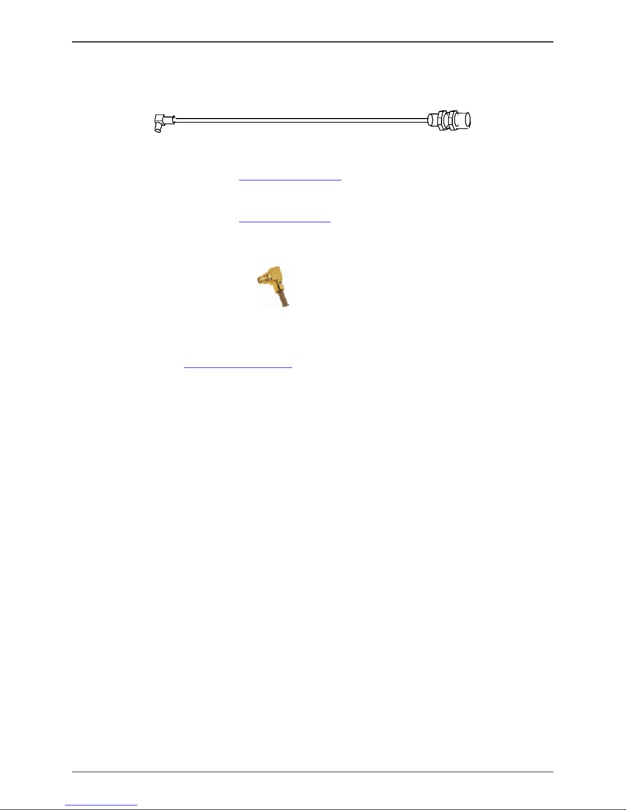
MMCX Plug
The SocketModem requires an MMCX plug to connect to an antenna.
MMCX Connector Example (right angle type)
A small MMCX / SMA adapter can be ordered, for example, from:
Amphenol
http://www.amphenol.com/
Order No: 908-31100
Multi-Tech Systems, Inc. SocketModem EDGE Embedded Wireless Modem Developer’s Guide (S000376A) 15
Page 16

Chapter 5 – SocketModem
Schematics
SocketModem Edge Diagrams
Chapter 5 – SocketModem Schematics
Top View of the SocketModem EDGE
Bottom View of the SocketModem EDGE
Multi-Tech Systems, Inc. SocketModem EDGE Embedded Wireless Modem Developer’s Guide (S000376A) 16
Page 17

Chapter 5 – SocketModem Schematics
SocketModem EDGE Block Diagram
Block Diagram for the SocketModem EDGE
Multi-Tech Systems, Inc. SocketModem EDGE Embedded Wireless Modem Developer’s Guide (S000376A) 17
Page 18

Chapter 5 – SocketModem Schematics
SocketModem EDGE Schematics
To view the text and numbers, increase the viewing percentage to 150% or print the page.
Multi-Tech Systems, Inc. SocketModem EDGE Embedded Wireless Modem Developer’s Guide (S000376A) 18
Page 19

Chapter 5 – SocketModem Schematics
Multi-Tech Systems, Inc. SocketModem EDGE Embedded Wireless Modem Developer’s Guide (S000376A) 19
Page 20

Chapter 6 – Application Considerations
Chapter 6 – Hardware Guidelines
General Guidelines for the Use of the
SocketModem
Hardware and RF
• Ground plane: Multi-Tech recommends having a common ground plane for analog, digital, and RF
grounds.
• ESD protection on serial link.
• Possible spurious emission radiated by the application to the RF receiver in the receiver band
The Antenna
The antenna sub-system and integration in the application is a major issue. It is a major issue in the choice of the
antenna cable (type, length, performances, thermal resistance, etc.)
These elements could affect EGPRS performances such as sensitivity and emitted power.
The antenna should be isolated as much as possible from the digital circuitry including the interface signals.
Multi-Tech recommends shielding the terminal. On terminals including the antenna, a poor shielding could
dramatically affect the sensitivity of the terminal. Subsequently, the power emitted through the antenna could
affect the application.
Soldering and Cleaning the SocketModem
The pins of the SocketModem may be hand soldered or wave soldered. If wave soldered, the temperature on the
top of the SocketModem must not exceed 100° C.
There should be no solvent or water washing of the SocketModem.
Do not use a hot air gun on the SocketModem.
Multi-Tech Systems, Inc. SocketModem EDGE Embedded Wireless Modem Developer’s Guide (S000376A) 20
Page 21

Appendix A – Warranty and Repairs
Appendix A – Warranty and Repairs
Multi-Tech Warranty Statement
Multi-Tech Systems, Inc., (hereafter “MTS”) warrants that its products will be free from defects in material or
workmanship for a period of two years from date of purchase, or if proof of purchase is not provided, two years from
date of shipment.
MTS MAKES NO OTHER WARRANTY, EXPRESS OR IMPLIED, AND ALL IMPLIED WARRANTIES OF
MERCHANTABILITY AND FITNESS FOR A PARTICULAR PURPOSE ARE HEREBY DISCLAIMED.
This warranty does not apply to any products which have been damaged by lightning storms, water, or power surges
or which have been neglected, altered, abused, used for a purpose other than the one for which they were
manufactured, repaired by Customer or any party without MTS’s written authorization, or used in any manner
inconsistent with MTS’s instructions.
MTS’s entire obligation under this warranty shall be limited (at MTS’s option) to repair or replacement of any products
which prove to be defective within the warranty period or, at MTS’s option, issuance of a refund of the purchase price.
Defective products must be returned by Customer to MTS’s factory — transportation prepaid.
MTS WILL NOT BE LIABLE FOR CONSEQUENTIAL DAMAGES, AND UNDER NO CIRCUMSTANCES WILL ITS
LIABILITY EXCEED THE PRICE FOR DEFECTIVE PRODUCTS.
Repair Procedures for U.S. and Canadian Customers
In the event that service is required, products may be shipped, freight prepaid, to our Mounds View, Minnesota
factory:
Multi-Tech Systems, Inc.
2205 Woodale Drive
Mounds View, MN 55112
Attn: Repairs, Serial # ____________
A Returned Materials Authorization (RMA) is not required. Return shipping charges (surface) will be paid by MTS to
destinations in U.S. and Canada.
Please include, inside the shipping box, a description of the problem, a return shipping address (must have street
address, not P.O. Box), your telephone number, and if the product is out of warranty, a check or purchase order for
repair charges.
For out of warranty repair charges, go to www.multitech.com/DOCUMENTS/Company/warranty/
Extended two-year overnight replacement service agreements are available for selected products. Please call MTS
customer service at (888) 288-5470 or visit our web site at www.multitech.com/PARTNERS/Programs/orc/
on rates and coverage’s.
Please direct your questions regarding technical matters, product configuration, verification that the product is
defective, etc., to our Technical Support department at (800) 972-2439 or email support@multitech.com
direct your questions regarding repair expediting, receiving, shipping, billing, etc., to our Repair Accounting
department at (800) 328-9717 or (763) 717-5631, or email mtsrepair@multitech.com
Repairs for damages caused by lightning storms, water, power surges, incorrect installation, physical abuse, or usercaused damages are billed on a time-plus-materials basis.
.
for details
. Please
Multi-Tech Systems, Inc. SocketModem EDGE Embedded Wireless Modem Developer’s Guide (S000376A) 21
Page 22

Appendix A – Warranty and Repairs
Repair Procedures for International Customers (Outside U.S.A. and Canada)
Your original point of purchase Reseller may offer the quickest and most economical repair option for your Multi-Tech
product. You may also contact any Multi-Tech sales office for information about the nearest distributor or other repair
service for your Multi-Tech product. The Multi-Tech sales office directory is available at
www.multitech.com/PARTNERS/Channels/offices/
In the event that factory service is required, products may be shipped, freight prepaid to our Mounds View, Minnesota
factory. Recommended international shipment methods are via Federal Express, UPS or DHL courier services, or by
airmail parcel post; shipments made by any other method will be refused. A Returned Materials Authorization (RMA)
is required for products shipped from outside the U.S.A. and Canada. Please contact us for return authorization and
shipping instructions on any International shipments to the U.S.A. Please include, inside the shipping box, a
description of the problem, a return shipping address (must have street address, not P.O. Box), your telephone
number, and if the product is out of warranty, a check drawn on a U.S. bank or your company’s purchase order for
repair charges. Repaired units shall be shipped freight collect, unless other arrangements are made in advance.
Please direct your questions regarding technical matters, product configuration, verification that the product is
defective, etc., to our Technical Support department nearest you or email support@multitech.com
U.S., please direct your questions regarding repair expediting, receiving, shipping, billing, etc., to our Repair
Accounting department at +(763) 717-5631 in the U.S.A., or email mtsrepair@multitech.com.
Repairs for damages caused by lightning storms, water, power surges, incorrect installation, physical abuse, or usercaused damages are billed on a time-plus-materials basis.
. When calling the
Repair Procedures for International Distributors
International distributors should contact their MTS International sales representative for information about the repairs
for their Multi-Tech product.
Please direct your questions regarding technical matters, product configuration, verification that the product is
defective, etc., to our International Technical Support department at +(763)717-5863. When calling the U.S., please
direct your questions regarding repair expediting, receiving, shipping, billing, etc., to our Repair Accounting
department at +(763) 717-5631 in the U.S.A. or email mtsrepair@multitech.com
Repairs for damages caused by lightning storms, water, power surges, incorrect installation, physical abuse, or usercaused damages are billed on a time-plus-materials basis.
.
Multi-Tech Systems, Inc. SocketModem EDGE Embedded Wireless Modem Developer’s Guide (S000376A) 22
Page 23

Index
Index
A
aircraft and safety.......................................................7
antenna ....................................................6, 14, 15, 20
antenna cable...........................................................20
AT commands documentation ...................................4
B
blasting areas and safety ...........................................7
Block Diagram..........................................................17
bursts .......................................................................12
C
Certifications ..............................................................5
children and safety .....................................................7
Cleaning the SocketModem .....................................20
D
Developer’s Kit ...........................................................5
driving safety ..............................................................7
E
efficient modem operation..........................................6
Electrical characteristics...........................................12
Electromagnetic Interference Considerations ............7
electronic devices and safety .....................................6
ESD protection .........................................................20
ETSI .........................................................................14
explosive atmospheres and safety .............................8
Exposure to RF Energy..............................................6
G
gain ............................................................................8
H
Handling precautions .................................................7
Hardware and RF.....................................................20
I
idle mode .................................................................12
Instructions to OEMs..................................................6
L
LEDs and Status ......................................................11
M
Mechanical Drawing...................................................9
medical electronic equipment and safety ...................6
MMCX (Miniature Micro Connector).........................14
O
operating conditions ...................................................6
P
Pin Descriptions .......................................................10
Product Description....................................................4
R
radio .........................................................................14
Radio Characteristics ...............................................14
Receiver Features....................................................14
Repairs.....................................................................21
RF Exposures ............................................................8
RF Performances .....................................................14
RF safety....................................................................6
S
safety .........................................................................6
Safety Compliance.....................................................8
Serial Test/Demo Board Components......................16
SIM Connector .........................................................14
SIM Interface Electrical Characteristics....................13
SIMCLK....................................................................13
SIMDATA .................................................................13
SIMRST ...................................................................13
SIMVCC ...................................................................13
Soldering the SocketModem ....................................20
T
Transmitter Features................................................14
V
vehicle electronic equipment and safety ....................6
W
Warranty ..................................................................21
Multi-Tech Systems, Inc. SocketModem EDGE Embedded Wireless Modem Developer’s Guide (S000376A) 23
 Loading...