

Page 1

RouteFinder
Internet Security Appliance
RF850
RF860
®
User Guide
Page 2

Copyright and Technical Support
User Guide
RouteFinder RF850/860
Document Number: S000400E, Revision E
This publication may not be reproduced, in whole or in part, without prior expressed written permission from
Multi-Tech Systems, Inc. All rights reserv ed.
Copyright © 2006-2008 by Multi-Tech Systems, Inc.
Multi-Tech Systems, Inc. makes no representations or warranties with respect to the contents hereof and
specifically disclaims any implied warranties of merchantability or fitness for any particular purpose.
Furthermore, Multi-Tech Systems, Inc. reserves the right to revise this publication and to make changes from
time to time in the content hereof without obligation of Multi-Tech Systems, Inc. to notify any person or
organization of such revisions or changes.
Record of Revisions
Revision
A 04/17/06 Initial release. Software version 3.30.
05/24/06 Corrections made on 5/24: Changed all references to the content filtering
B 06/01/06 Added explanation of Load Balancing on the Network Setup screen.
C 04/05/07 Updated for Software 3.32. Changed examples 1 and 2. Added Table of
D 09/05/07 Added "Description of Syslog Messages" to Appendix A – Disposition of
E 04/14/08 Changes for software version 3.34. Added a drawing of the RouteFinder with
Patents
This device is covered by one or more of the following U.S. Patent Numbers: 6,219,708; 5,301,274; 5,309,562;
5,355,365; 5,355,653; 5,452,289; 5,453.986.
The modem is covered by one or more of the following U.S. Patent Numbers: 6,031,867; 6,012,113; 6,009,082;
5,905,794; 5,864,560; 5,815,567; 5,815,503; 5,812,534; 5,809,068; 5,790,532; 5,764,628; 5,764,627;
5,754,589; D394,250; 5,724,356; 5,673,268; 5,673,257; 5,644,594; 5,628,030; 5,619,508; 5,617,423; 5,600,649;
5,592,586; 5,577,041; 5,574,725; D374,222; 5,559,793; 5,546,448; 5,546,395; 5,535,204; 5,500,859; 5,471,470;
5,463,616; 5,453,986; 5,452,289; 5,450,425; D361,764; D355,658; D355,653; D353,598; D353,144; 5,355,365;
5,309,562; 5,301,274 Other Patents Pending
Trademarks
Registered Trademarks of Multi-Tech Systems, Inc. include: Multi-Tech, the Multi-Tech logo, and RouteFinder.
Windows is a registered trademark of Microsoft Corporation in the United States and other countries.
Kaspersky Anti-Virus engine copyright by Kaspersky Labs. All products or technologies a re the trademarks or
registered trademarks of their respective holders.
Technical Support
Country By Email By Phone
Europe, Middle East, Africa support@multitech.co.uk
U.S., Canada, all others support@multitech.com
World Headquarters
Multi-Tech Systems, Inc.
2205 Woodale Drive
Mounds View, Minnesota 55112
(763) 785-3500 or (800) 328-9717
Fax 763-785-9874
Internet Address: http://www.multitech.com
Date Description
software specifying 30-day free trial; add RAM to specifications; and reworded
Memory Upgrade description in Appendix C.
Commonly Supported Subnet Addresses to the Appendix. Updated the
Technical Support contact list.
Events. Updated the warranty statement. Added an RJ-45 Ethernet cable to the
Ship Kit list. Added an FAQ about the Ethernet ports supporting 10/100 Mbps
half-duplex and full duplex lines.
mounting brackets.
+(44) 118 959 7774
800-972-2439 or +763-785-3500
Multi-Tech Systems, Inc. RouteFinder RF850/860 User Guide (PN S000400E) 2
Page 3

Table of Contents
Contents
Chapter 1 – Product Description and Specifications........................................................................................7
Product Description...........................................................................................................................................7
RouteFinder Documentation.............................................................................................................................7
RouteFinder Features.......................................................................................................................................7
Safety Warnings................................................................................................................................................8
Safety Recommendations for Rack Installations..............................................................................................8
Shutdown Caution.............................................................................................................................................8
Ship Kit Contents..............................................................................................................................................9
License Keys.....................................................................................................................................................9
Typical Applications........................................................................................................................................10
Specifications..................................................................................................................................................11
Chapter 2 – Installation and Setup.................................................................................................................... 13
System Administrator Planning.......................................................................................................................13
Planning the Network......................................................................................................................................13
Establishing an Address Table....................................................................................................................... 13
Front Panel .....................................................................................................................................................14
Cabling Procedure..........................................................................................................................................15
Rackmount Bracket Installation......................................................................................................................15
Setting up a Workstation and Starting the RouteFinder.................................................................................16
Establish TCP/IP Communication...................................................................................................................16
Set a Fixed IP Address..............................................................................................................................16
Obtain a Dynamic IP Address...................................................................................................................16
Open a Web Browser .....................................................................................................................................18
Login............................................................................................................................................................... 18
Web Management Software Opens................................................................................................................19
Navigating Through the Software Screens.....................................................................................................19
Screen Buttons..........................................................................................................................................20
Menus and Sub-Menus.............................................................................................................................20
Chapter 3 – Configuration Using Web Management Software....................................................................... 21
Initial Configuration Step.................................................................................................................................21
Second Configuration Step – Using the Wizard Setup................................................................................... 22
The Wizard Setup Screen – Configuration Example......................................................................................23
Chapter 4 – Configuration Examples................................................................................................................ 24
Example 3 – Remote Client-to-LAN Configuration Using DNAT and Aliasing............................................... 36
Example 4 – Client-to-LAN Configuration Using PPTP Tunneling................................................................. 37
Checking the Tunnel.......................................................................................................................................37
Chapter 5 – URL Categorization ........................................................................................................................ 38
Important Settings........................................................................................................................................... 38
Setting Up HTTP Proxy and URL Filtering.....................................................................................................38
Chapter 6 – RouteFinder Software ....................................................................................................................41
Menu Bar ........................................................................................................................................................41
Administration................................................................................................................................................. 42
Administration > System Setup.................................................................................................................42
Multi-Tech Systems, Inc. RouteFinder RF850/860 User Guide (PN S000400E) 3
Page 4

Table of Contents
Administration > SSH................................................................................................................................44
Administration > SNTP Client....................................................................................................................45
Administration > Administrative Access....................................................................................................46
Administration > Change Root Password.................................................................................................47
Administration > Site Certificate................................................................................................................48
Administration > License Key....................................................................................................................49
Administration > Intrusion Detection .........................................................................................................50
Administration > Tools...............................................................................................................................52
Administration > System Scheduler..........................................................................................................55
Administration > Factory Defaults.............................................................................................................55
Administration > User Authentication > Local Users.................................................................................56
Administration > User Authentication > RADIUS & SAM..........................................................................57
Administration > Version Information........................................................................................................59
Administration > Restart............................................................................................................................59
Administration > Shutdown .......................................................................................................................59
Networks & Services....................................................................................................................................... 60
Networks & Services > Networks..............................................................................................................60
Networks & Services > Services ...............................................................................................................62
Networks & Services > Network Groups...................................................................................................64
Networks & Services > Service Groups....................................................................................................65
Proxy...............................................................................................................................................................66
General Information About Proxies...........................................................................................................66
Proxy > HTTP Proxy .................................................................................................................................67
Proxy > HTTP Proxy > Custom Filters......................................................................................................71
Proxy > SMTP Proxy.................................................................................................................................72
Proxy > SMTP Proxy > SMTP SPAM Filtering..........................................................................................75
Proxy > POP3 Proxy .................................................................................................................................78
Proxy > POP3 Proxy > POP3 SPAM Filtering ..........................................................................................79
Proxy > POP3 Advanced Configuration....................................................................................................81
Proxy > SOCKS Proxy ..............................................................................................................................81
Proxy > DNS Proxy...................................................................................................................................83
Network Setup ................................................................................................................................................84
About Interfaces........................................................................................................................................84
About the Interface Screen .......................................................................................................................84
Network Setup > Interface.........................................................................................................................85
Network Setup > PPP ...............................................................................................................................88
Change Your Country/Region Code .........................................................................................................89
Network Setup > PPPoE...........................................................................................................................90
Network Setup > DHCP Client..................................................................................................................91
Network Setup > Dynamic DNS (DDNS) ..................................................................................................92
Network Setup > Routes...........................................................................................................................93
Network Setup > Masquerading................................................................................................................94
Network Setup > SNAT.............................................................................................................................95
Network Setup > DNAT.............................................................................................................................96
Network Setup > Load Balancing..............................................................................................................97
Network Setup > High Availability.............................................................................................................99
DHCP Server................................................................................................................................................101
DHCP Server > Subnet Settings.............................................................................................................101
DHCP Server > Fixed Addresses............................................................................................................101
Tracking........................................................................................................................................................ 102
Tracking > Accounting.............................................................................................................................102
Tracking > Update Services....................................................................................................................103
Tracking > Backup ..................................................................................................................................105
Tracking > Version Control......................................................................................................................107
Multi-Tech Systems, Inc. RouteFinder RF850/860 User Guide (PN S000400E) 4
Page 5

Table of Contents
Packet Filters................................................................................................................................................108
Packet Filters > Packet Filter Rules........................................................................................................108
Packet Filters > ICMP .............................................................................................................................110
Packet Filters > Advanced ......................................................................................................................111
Packet Filters > Enable/Disable Log.......................................................................................................113
Packet Filters > QoS ...............................................................................................................................114
VPN (Virtual Private Networks).....................................................................................................................116
VPN > IPSec ...........................................................................................................................................116
Introduction to Virtual Private Networks..................................................................................................116
VPN > X.509 Certificates ........................................................................................................................121
VPN > IPSec Bridging.............................................................................................................................121
VPN > PPTP............................................................................................................................................123
Wizard Setup – Screen Description..............................................................................................................125
Statistics & Logs ...........................................................................................................................................127
Statistics & Logs > Uptime ......................................................................................................................128
Statistics and Logs > Hardware ..............................................................................................................128
Statistics and Logs > Networks...............................................................................................................128
Statistics & Logs > Interfaces..................................................................................................................131
Statistics & Logs > SMTP Proxy .............................................................................................................131
Statistics & Logs > Accounting................................................................................................................132
Statistics & Logs > Self Monitor ..............................................................................................................132
Statistics & Logs > IPSec........................................................................................................................133
Statistics & Logs > PPTP ........................................................................................................................133
Statistics & Logs > Packet Filter..............................................................................................................134
Statistics & Logs > Port Scans................................................................................................................135
Statistics & Logs > View Logs.................................................................................................................135
Statistics & Logs > HTTP Access............................................................................................................136
Statistics & Logs > DHCP .......................................................................................................................137
Statistics & Logs > SMTP Virus Quarantines..........................................................................................137
Statistics & Logs > POP3 Virus Quarantines..........................................................................................137
Statistics & Logs > SMTP SPAM Quarantines........................................................................................137
Statistics & Logs > Administrative Authentication Log............................................................................137
Statistics & Logs > QoS ..........................................................................................................................138
Statistics & Logs > DDNS Log ................................................................................................................138
Chapter 7 – User Authentication Methods......................................................................................................139
Proxy Services and Authentication Methods...........................................................................................139
Which Method Should You Choose?......................................................................................................139
Authentication Setup.....................................................................................................................................140
Setting Up RADIUS Authentication.........................................................................................................140
Setting Up a Microsoft IAS RADIUS Server............................................................................................140
Setting Up NT/2000 SAM (SMB) Authentication.....................................................................................141
Chapter 8 – Frequently Asked Questions (FAQs)..........................................................................................142
Chapter 9 – Troubleshooting ...........................................................................................................................147
Appendix A – Disposition of Events for the RouteFinder v3.xx................................................................... 149
Appendix B – The RouteFinder Rescue Kernel..............................................................................................156
Appendix C – Table of Commonly Supported Subnet Addresses............................................................... 160
Appendix D – Hardware Upgrades & Add-ons and Software Add-ons ....................................................... 162
Hardware Upgrades and Add-ons................................................................................................................162
Software Add-ons .........................................................................................................................................163
Appendix E – RouteFinder Maintenance ........................................................................................................164
Multi-Tech Systems, Inc. RouteFinder RF850/860 User Guide (PN S000400E) 5
Page 6

Table of Contents
Appendix F – Ordering Accessories............................................................................................................... 166
SupplyNet Online Ordering Instructions..................................................................................................166
Appendix G – Multi-Tech Systems, Inc. Warranty, Repairs and Replacement Policies............................ 167
Appendix H – Regulatory Compliance............................................................................................................ 169
Appendix I – License Agreements................................................................................................................... 171
GNU GENERAL PUBLIC LICENSE........................................................................................................173
URL Content Filtering End-User License Agreement.............................................................................175
Kaspersky Standard End User License Agreement................................................................................177
Appendix J – Waste Electrical and Electronic Equipment Directive (WEEE)............................................. 179
Glossary.............................................................................................................................................................180
Index...................................................................................................................................................................191
Multi-Tech Systems, Inc. RouteFinder RF850/860 User Guide (PN S000400E) 6
Page 7

Chapter 1 – Product Description and Specifications
Chapter 1 – Product Description and
Specifications
Product Description
The RouteFinder® all-in-one security appliance is designed to maximize network security without compromising
network performance. It offers a Stateful Packet Inspection firewall for the ultimate in firewall security. In
addition, it provides optional email anti-virus protection, 30-day free trial content filtering software, as well as
spam filtering. The RouteFinder security appliance uses data encryption, user authentication, and the Internet to
securely connect telecommuters, remo t e offices, customers, or suppliers to the corporate office while avoiding
the cost of private leased lines or dial-up charges.
RouteFinder Documentation
The Quick Start Guide is intended to provide the experienced system administrator the information needed to
quickly get the RouteFinder up and running.
The User Guide with more detailed information is provided on the RouteFinder CD or the Multi-Tech Systems,
Inc. Web site.
RouteFinder Features
See the RouteFinder Data Sheet for detailed descriptions of the following features:
• Supports IPSec and PPTP VPN tunneling
• Utilizes Triple Data Encryption Standard (3DES) and AES encryption
• Stateful Packet Inspection firewall with packet filter rules, DNAT, SNAT, and IP Masquerade
• Optional content filtering subscription (30-day free trial included)
• Optional anti-virus subscription
• Free spam filtering for unsolicited bulk emails
• QoS (Quality of Service) / Bandwidth allocation
• Dual WAN load balancing and failover
• High availability
• Automatic dial-backup with built-in modem (RF860) or via an external dial-up modem or ISDN terminal
adapter (RF850)
• Automatic system updates to protect your network against the latest threats and DoS attacks
• Application layer security using SMTP, HTTP, DNS, and SOCKS proxies
• Secure local or remote management using HTTP, HTTPS, or SSH
• Reporting function provides valuable troubleshooting information
• Three built-in Ethernet ports (LAN, WAN, WAN2/DMZ)
• Shared Internet access via PPPoE, DHCP or static IP
• Internet access control tools provide client and site filtering
• Traffic monitoring and reporting
• IP address mapping/port forwarding and DMZ port
• RoHS compliant
• Two-year warranty
Multi-Tech Systems, Inc. RouteFinder RF850/860 User Guide (PN S000400E) 7
Page 8

Chapter 1 – Product Description and Specifications
Safety Warnings
Lithium Battery Caution
Danger of explosion if battery is incorrectly replaced. A lithium battery on the RouteFinder PC board provides
backup power for the time-keeping capability. The battery has an estimated life expectancy of ten years. When it
starts to weaken, the date and time may be incorrect. If the battery fails, send the board back to Multi-Tech for
battery replacement.
Ethernet Ports Caution
The Ethernet ports are not designed to be connected to a Public Telecommunication Network.
Software Recovery CD Warning
Do not use the Software Recovery CD for any purpose except for re-installing software onto the RouteFinder
hard drive.
Telecom Warnings for Modem Operation
• Never install telephone wiring during a lightning storm.
• This product must be disconnected from the telephone network interface when servicing.
• This product is to be used with UL and cUL listed computers.
• Never touch uninsulated telephone wires or terminals unless the telephone line has been disconnected
at the network interface.
• Use caution when installing or modifying telephone lines.
• Avoid using a telephone during an electrical storm. There may be a remote risk of electri cal sho ck from
lightning.
• Do not use the telephone to report a gas leak in the vicinity of the leak.
• To reduce the risk of fire, use only No. 26 AWG or larger telecommunications line cord.
• Never install telephone jacks in a wet location unless the jack is specifically designed for wet locations.
Safety Recommendations for Rack Installations
• Ensure proper installation of the RouteFinder in a closed or multi-unit enclosure by following the
recommended installation as defined by the enclosure manufacturer.
• IMPORTANT: Do not place the RouteFinder directly on top of other equipment or place other equipment
directly on top of the RouteFinder.
• If installing the RouteFinder in a closed or multi-unit enclosure, ensure adequate airflow within the rack
so that the maximum recommended ambient temperature is not exceeded.
• Ensure that the RouteFinder is properly connected to earth ground via a grounded power cord. If a
power strip is used, ensure that the power strip provides adequate grounding of the attached apparatus.
• Ensure that the main supply circuit is capable of handling the load of the RouteFinder. Refer to the
power label on the equipment for load requirements.
• Maximum ambient temperature for the RouteFinder is 50 degrees Celsius (120° F).
• This equipment should only be installed by properly qualified service personnel.
• Only connect like circuits. In other words, connect SELV (Secondary Extra Low Voltage) circuits to
SELV circuits and TN (Telecommunications Network) circuits to TN circuits.
Shutdown Caution
Never unplug the RouteFinder power until after you have performed the Shutdown process. If the RouteFinder
is not properly shut down before unplugging the Power, the next startup may take a little longer, or in the worst
case, data could be lost.
Multi-Tech Systems, Inc. RouteFinder RF850/860 User Guide (PN S000400E) 8
Page 9
Chapter 1 – Product Description and Specifications
Ship Kit Contents
The RouteFinder is shipped with the following:
• One Multi-Tech Systems, Inc. RouteFinder
• One external power supply with AC power cord
• RJ-45 Ethernet cable
• One printed Quick Start Guide
• Two rack mounting brackets and four mounting screws.
• One RouteFinder documentation CD which contains documentation, license agreements, Adobe
Acrobat Reader, and license keys.
• A 30-day evaluation copy of VPN client software on CD (not the full working version).
• One RouteFinder Software Recovery CD.
Warning: Do not use the Software Recovery CD for any purpose except for re-installing software onto the
RouteFinder hard drive.
Note: If any of these items are missing, contact Multi-Tech Systems or your dealer or distributor. Inspect the
contents for signs of any shipping damage. If damage is observed, do not power up the RouteFinder; contact
Technical Support at Multi-Tech Systems, Inc. for advice.
License Keys
here to Find the License Key Numbers
icense Key numbers are printed on labels that are placed:
• On the bottom of the RouteFinder chassis
• On the compact flash drive inside the chassis
• On the front cover of the Quick Start Guide.
System License Key
Each RouteFinder ships with a unique individual system License Key, a 20-digit alphanumeric number.
You can view License Key information from the RouteFinder's Web Management software at Administration >
License Key. This screen shows the entered License Key number and indicate s whether it is a valid License
Key number.
The License Key number is tied to and tracked with your RouteFinder's serial number. Whenever you require
additional licenses, you must first provide Multi-Tech with your current License Key and serial number
information in order for us to update your RouteFinder. With a valid License Key, you are entitled to use MultiTech’s Update service and support.
Note: The system key is already entered into the VPN setup.
URL Categorization License Key
An 15-digit numeric key Universal Resource Locator (URL) Categorization License Key is also shipped with your
RouteFinder as part of the 30-day trial offer of the URL software. This Key allows you to set up a URL database
that limits clients’ access to places on the Internet by blocking sites you do not want accessed. In other words,
you can deny users access to various categories of Web sites you select.
What to Do When a Trial License Key Expires
If the license key is a trial key, after expiry of the license period, the WAN interface of the RouteFinder
will shut down. If the DHCP client or PPPoE is enabled, they will be disabled. You can connect to the
RouteFinder through the LAN interface and enter another valid license key to proceed further. You have
to manually enable the DHCP client / PPPoE after entering another valid license key.
AntiVirus License Key
AntiVirus software with its corresponding License Key is available as a special purchase from Multi-Tech.
Multi-Tech Systems, Inc. RouteFinder RF850/860 User Guide (PN S000400E) 9
Page 10
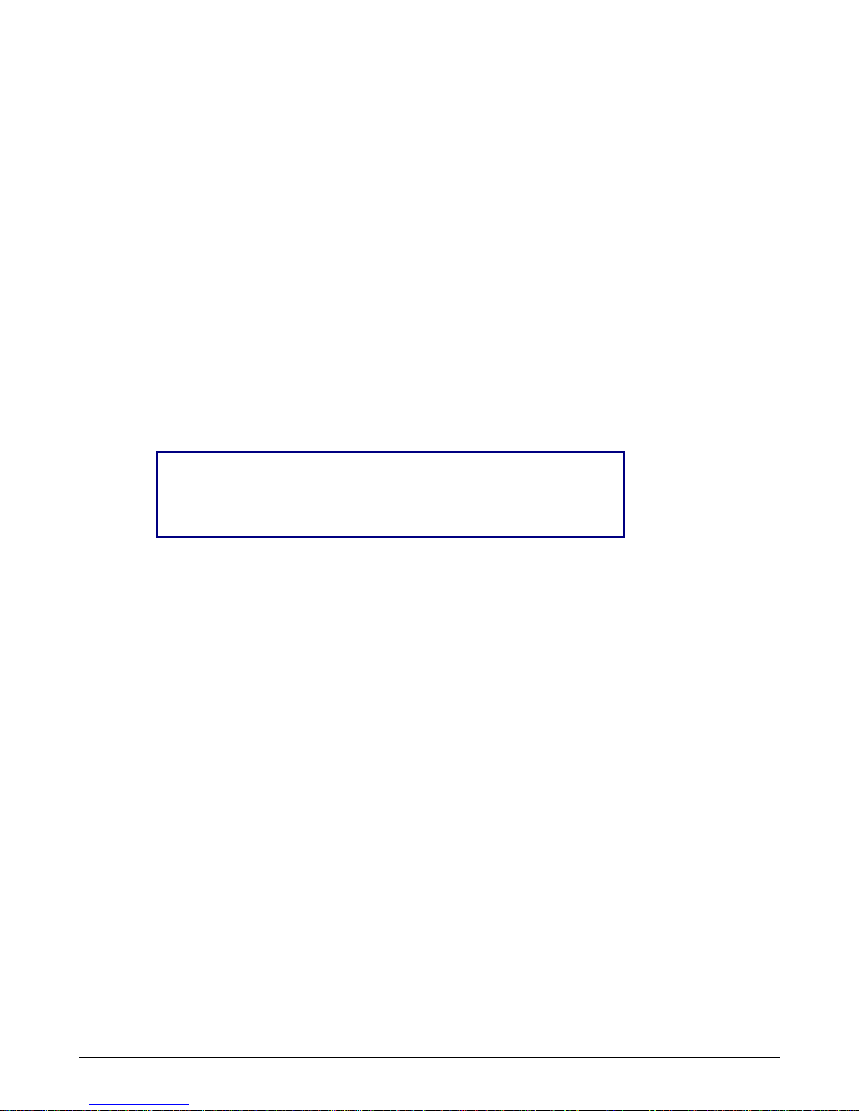
Typical Applications
Remote User VPN. The client-to-
LAN VPN application replaces
traditional dial-in remote access by
allowing a remote user to connect
to the corporate LAN through a
secure tunnel over the Internet.
The advantage is that a remote
user can make a local call to an
Internet Service Provider, without
sacrificing the company’s security,
as opposed to a long distance call
to the corporate remote access
server.
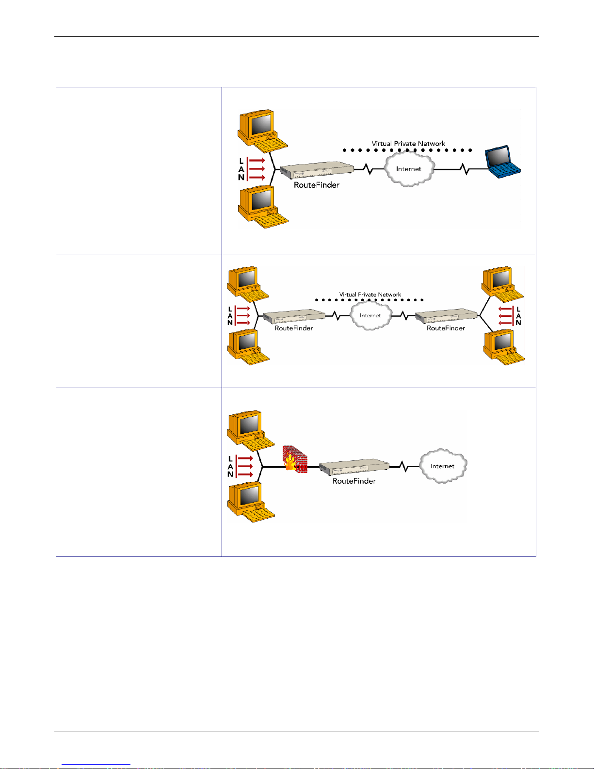
Branch Office VPN. The LAN-to-
LAN VPN application sends
network traffic over the branch
office Internet connection instead
of relying on dedicated leased line
connections. This can save
thousands of dollars in line costs
and reduce overall hardware and
management expenses.
Firewall Security. As businesses
shift from dial-up or leased line
connections to always-on
broadband Internet connections,
the network becomes more
vulnerable to Internet hackers.
The RouteFinder provides a full-
featured firewall based on
Stateful Packet Inspection
technology and NAT protocol to
provide security from intruders
attempting to access the office
LAN.
Chapter 1 – Product Description and Specifications
Multi-Tech Systems, Inc. RouteFinder RF850/860 User Guide (PN S000400E) 10
Page 11

Chapter 1 – Product Description and Specifications
Specifications
Appliance Features RF850 RF860
Ethernet Ports 10/100BaseT (LAN, WAN,
WAN2/DMZ)
Number of Network Users 50 100
RAM 512MB (can be upgraded to a
total of 2GB)
Rackmount or Standalone Both Both
Firewall Features
Stateful Packet Inspection Yes Yes
Anti-Virus Option Yes Yes
Content Filtering Yes Yes
Spam Filtering Yes Yes
Application Proxies Yes Yes
Port and IP Filtering Yes Yes
Denial of Service Protection (DoS) Yes Yes
Network Address Translation (NAT) Yes Yes
Virtual Server Yes Yes
Intrusion/Port Scan Detection Yes Yes
H.323 Pass Through Yes Yes
VPN Features
Remote User (Client-to-LAN) Yes Yes
Branch Office (LAN-to-LAN) Yes Yes
3DES/AES Encryption Yes Yes
Encryption Throughput 5M 15M
IPSec/PPTP VPN Yes Yes
Total Number of Tunnels 50 100
Dynamic-to-Dynamic Tunneling Yes Yes
VPN Using FQDN Yes Yes
x.509 Certificates Yes Yes
Management Features
Email Alerts Yes Yes
Local & Remote Management Yes Yes
Logging Yes Yes
Reporting Yes Yes
Web Based (HTTP, HTTPS/SSL) Yes Yes
Secure Shell (SSH) Yes Yes
Syslog Yes Yes
Other Features
Shared Internet Access Yes Yes
Automatic Dial-Backup Yes Yes
Integrated Modem No Yes
Dual WAN Load Balancing Yes Yes
Internet/VPN Failover Yes Yes
High Availability Yes Yes
QoS/Bandwidth Allocation Yes Yes
PPPoE Yes Yes
DHCP Client/Server Yes Yes
User Authentication (Web Acce ss) Yes Yes
Live Updates Yes Yes
Warranty 2 Years 2 Years
10/100BaseT (LAN, WAN,
WAN2/DMZ)
1GB (can be upgraded to a total of
2GB)
Multi-Tech Systems, Inc. RouteFinder RF850/860 User Guide (PN S000400E) 11
Page 12

Chapter 1 – Product Description and Specifications
Power & Physical Description RF850 RF860
Power - Voltage & Frequency 100-240v AC, 50-60 Hz 100-240v AC, 50-60 Hz
Power Consumption 42 Watts +12Vdc @ 3.5A 42 Watts +12Vdc @ 3.5A
Physical Description Dimensions:
12" w × 1.75" h × 8" d;
(30.4cm × 4.45cm × 20.3cm)
Weight: 4.4 lbs. (2.0 kg)
Operating Environment Temperature Range:
32° to 120° F (0-50°C)
Humidity: 25-85%
Dimensions:
12" w × 1.75" h × 8" d;
(30.4cm × 4.45cm × 20.3cm)
Weight: 4.6 lbs. (2.1 kg)
Temperature Range:
32° to 120° F (0-50°C)
Humidity: 25-85% noncondensing
noncondensing
Approvals FCC Part 68
FCC Part 15 (Class A)
CE Mark
UL60950
FCC Part 68
FCC Part 15 (Class A)
CE Mark
UL60950
Multi-Tech Systems, Inc. RouteFinder RF850/860 User Guide (PN S000400E) 12
Page 13
Chapter 2 – Installation and Setup
Chapter 2 – Installation and Setup
System Administrator Planning
• The system administrator must complete these setup requirements before in stalling the RouteFinder
software:
• Set the correct configuration of the Default Gateway
• Install an HTTPS-capable browser (e.g., the latest version of Microsoft Internet Explorer or Netscape
Navigator)
• Activate JavaScript and Cascading Style Sheets
• Make sure that no proxies are entered in the browser
• If Secure Shell (SSH) is to be used, you must install an SSH client program (e.g., PuTTY in Windows or
the bundled SSH client in most Linux packages).
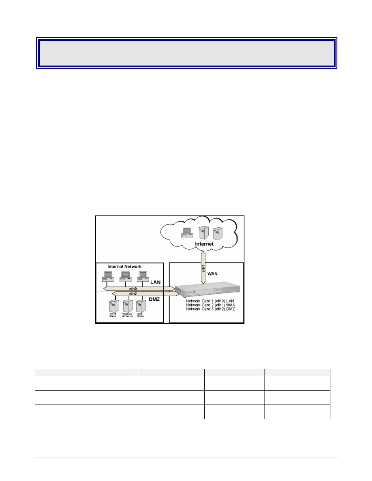
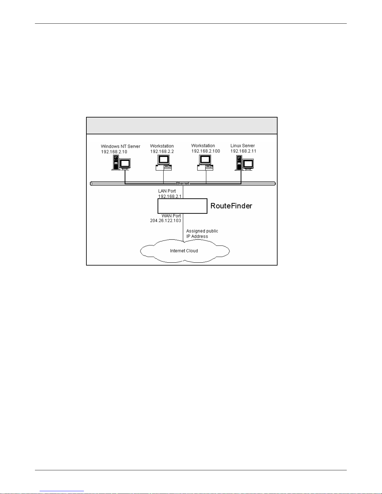
Planning the Network
Before you begin the installation process, you should plan your network and decide which computer i s to have
access to which services. This simplifies configuration and saves you a lot of time that you would otherwise
need for corrections and adjustments.
RouteFinder Connection between Your Internal Network and the External Network
Establishing an Address Table
Enter your configuration information into the appropriate field of the Address Table below. You can use this table
to keep track of your specific RouteFinder and network information (e.g., the IP address used, email lists, etc.)
and keep for future reference.
Network Card connected to the
internal network (LAN on eth0)
Network Card connected to the
external network (WAN on eth1)
Network Card connected to the
WAN2 / DMZ (eth2)
Multi-Tech Systems, Inc. RouteFinder RF850/860 User Guide (PN S000400E) 13
IP Address Net Mask Default Gateway
___.___.___.___
___.___.___.___
___.___.___.___
___.___.___.___
___.___.___.___
___.___.___.___
___.___.___.___
Page 14

Front Panel
LEDs Description
10MB
ACT
100MB
Disk ACT
Status
Power
WAN1, WAN2/DMZ Lights when a successful 10Base-T Internet connection is
established.
LAN Lights when a successful 10Base-T Ethernet connection is established.
WAN1, WAN2/DMZ Blinks when it is receiving or transmitting data.
LAN Blinks when it is receiving or transmitting data.
WAN1, WAN2/DMZ Lights when a successful 100Base-T Internet connection is
established.
LAN Lights when a successful 100Base-T Ethernet connection is established.
Lights when the disk drive is accessed.
When functioning normally, the LED blinks. The LED is a solid light when the
RouteFinder is booting up, saving the configuration, restarting, or updating the
firmware.
Lights when power is being supplied to the RouteFinder.
Chapter 2 – Installation and Setup
Multi-Tech Systems, Inc. RouteFinder RF850/860 User Guide (PN S000400E) 14
Page 15
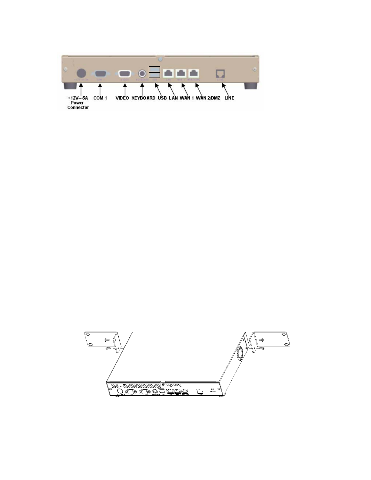
Chapter 2 – Installation and Setup
Cabling Procedure
Make the proper connections as illustrated in this drawing of the RouteFinder back panel.
Basic Connections
1. Using an RJ-45 Ethernet cable, connect the LAN jack to a PC, internal network switch, or hub.
Note: Use a cross-over Ethernet cable if connecting to a single device.
2. Using an RJ-45 Ethernet cable, connect the WAN 1 jack to a cable modem or DSL modem
connected to an Internet Service Provider.
3. Using the supplied POWER cord, plug one end into the RouteFinder power plug, and the other end
into a live power outlet.
Note: The status LED blinks continuously after power-up.
4. Wait for the RouteFinder to beep five times, indicating that it is ready to be configured with a Web
browser. This may take two or three minutes.
Optional Connections
1. Using an RJ-45 Ethernet cable, connect the WAN2 / DMZ jack to a network or DMZ device. For
example, a Voice over IP gateway.
2. Using a DB-9 cable, connect COM 1 port to a mouse or the COM port on a PC.
3. Using a DB-15 DSUB cable, connect the VIDEO port to a monitor.
4. Connect the Keyboard jack to a keyboard.
5. Using a USB connector, connect a memory stick, a floppy drive, a CD-ROM drive, a keyboard,
mouse, etc.
Rackmount Bracket Installation
The RouteFinder is shipped with two rackmount brackets and four rackmount screws for installing the
RouteFinder VPN into an industry-standard EIA 19-inch rack.
Note: The rackmount screws provided in this kit are included for the purpose of attaching the brackets to the
RouteFinder as shown below. It is up to you to provide the bracket-to-rack mounting screws.
Use the rack manufacturer’s documentation and procedures to safely and securely install the RouteFinder into
the rack.
RouteFinder Shown from the Back
Multi-Tech Systems, Inc. RouteFinder RF850/860 User Guide (PN S000400E) 15
Page 16
Chapter 2 – Installation and Setup
Setting up a Workstation and Starting the
RouteFinder
This section of the Quick Start covers the steps for setting up TCP/IP communication on the PC(s) connected to
the RouteFinder, starting up the RouteFinder, and opening the RouteFinder Web Management prog ram.
Establish TCP/IP Communication
The RouteFinders have built-in DHCP server functionality, so you can set the PC to obtain a dynamic IP
address. The following directions are for Windows 2000+/XP operating systems.
Set a Fixed IP Address
To set a Fixed IP Address, check Specify an IP address instead of Obtain an IP address automatically.
Then click OK.
1. Enter the workstation IP address as 192.168.2.x. Note that the x in the add ress stands for numbers 101
and up.
2. Enter the Subnet mask as 255.255.255.0
3. Enter the Default gateway as 192.168.2.1
4. Close out of the Control Panel.
5. Repeat these steps for each PC on your network.
OR
Obtain a Dynamic IP Address
To obtain a dynamic IP address so it can be assigned to the Ethernet port:
1. Make the RouteFinder connections as described on the previous two pages.
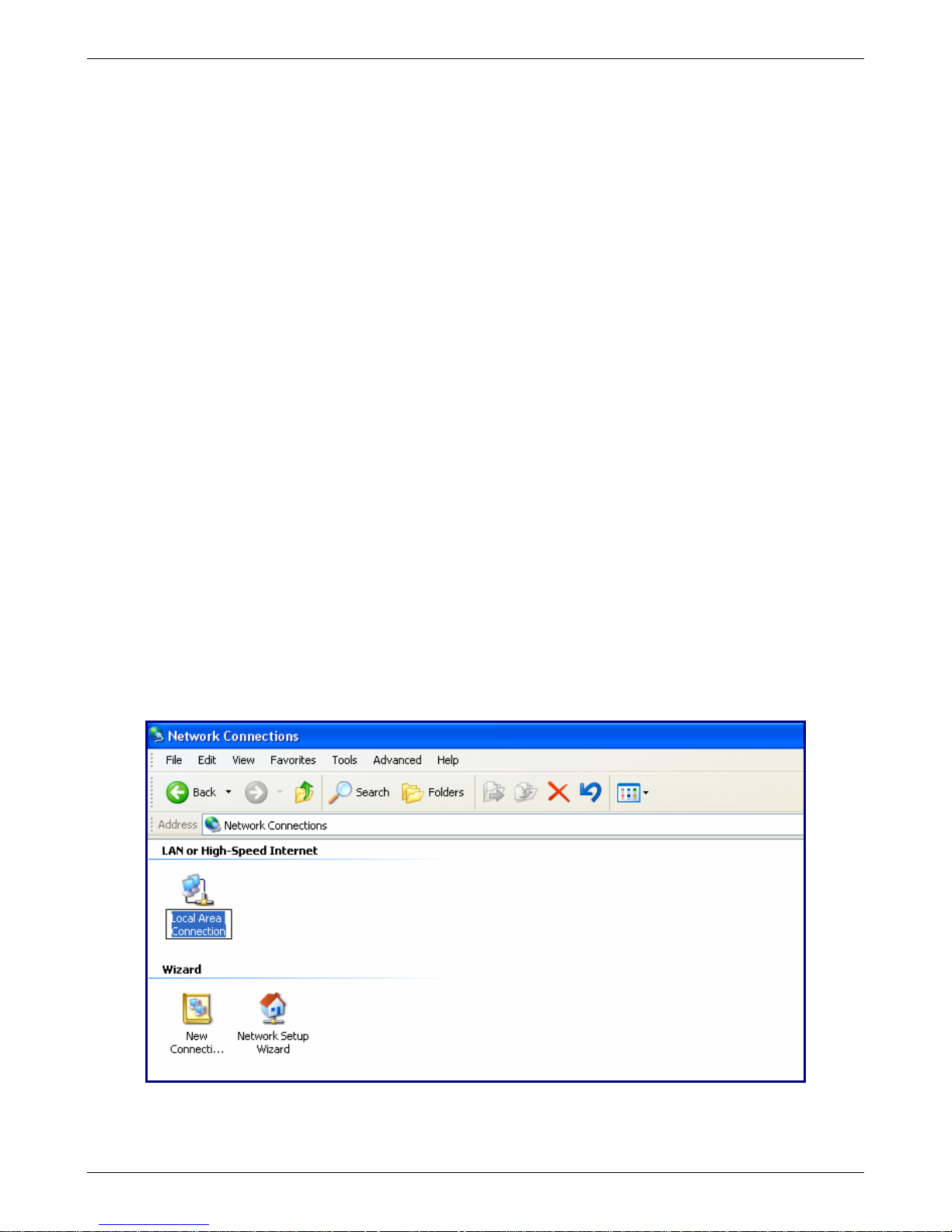
2. Click Start | Settings | Control Panel. Double-click the Network Connections icon.
3. The Network Connections screen displays. Right-click the Local Area Connection icon and choose
Properties from the drop down list.
Multi-Tech Systems, Inc. RouteFinder RF850/860 User Guide (PN S000400E) 16
Page 17
Chapter 2 – Installation and Setup
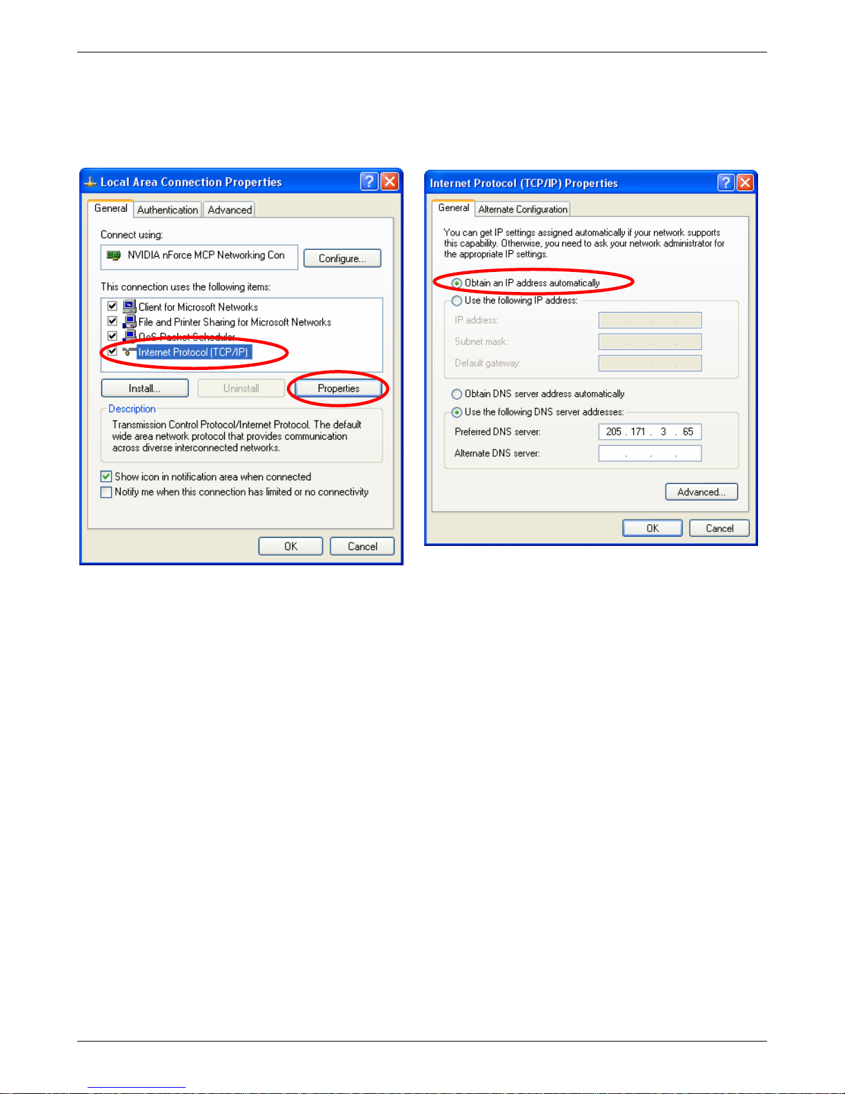
4. The Local Area Connection Properties dialog
box displays.
• Select Internet Protocol [TCP/IP].
• Click the Properties button.
5. Once you click the Properties button, the following
screen displays. To have your DHCP client obtain a
dynamic IP address, click the button for Obtain an
IP address automatically.
6. Close out of the Control Panel.
7. Repeat these steps for each PC on your network.
Multi-Tech Systems, Inc. RouteFinder RF850/860 User Guide (PN S000400E) 17
Page 18
Chapter 2 – Installation and Setup
Open a Web Browser
Note: Be sure that the RouteFinder is cabled and that the power is connected. See the cabling dra wing s at the
beginning of this chapter.
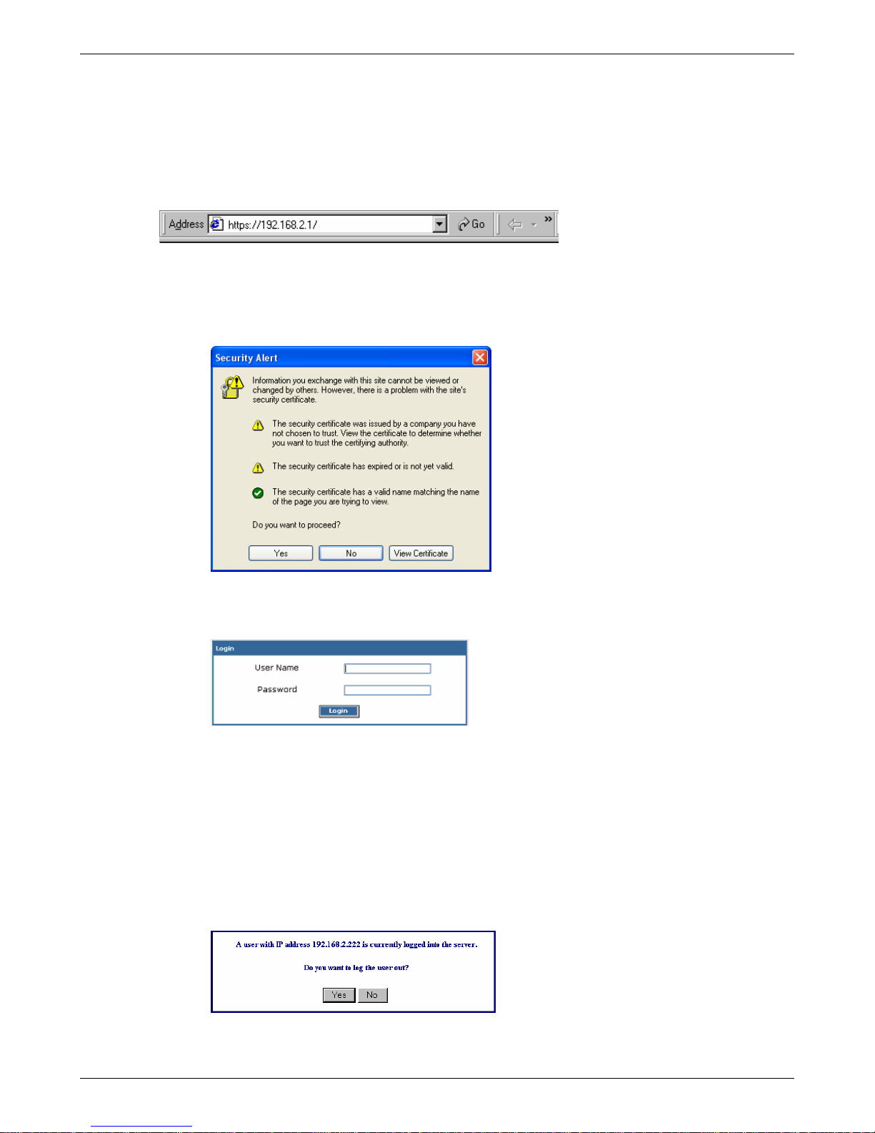
Bring up a Web browser on the workstation.
1. Type the default Gateway address: https://192.168.2.1
2. Press Enter
IMPORTANT: Be sure to type https (http will not work).
Note: Make sure your PC’s IP address is in the same network as the router’s IP address.
IPCONFIG is a tool for finding a computer’s default gateway and MAC address.
In some environments, one or more Security Alert screen(s) may display. At the following Security
Alert screen, click Yes and follow any additional on-screen prompts.
Login
The Login screen displays after you type the default Gateway address:
• Type the default User name: admin (all lower-case)
• Tab to the Password field and type the default password: admin (all lower-case ).
• Click the Login button.
Note: User name and Password entries are case-sensitive (both must be typed in lower-case). A password
can be up to 12 characters. If Windows displays the AutoComplete screen, you may want to click No to tell
Windows OS to not remember the password for security reasons.
• Password Caution: Use a safe password! Your first name spelled backwards is not a
sufficiently safe password; a password such as xfT35$4 is better. It is recommended that you
change the default password. Create your own password.
• If someone else is already logged into the RouteFinder or you were logged in recently, the
following message displays.
Click Yes. (If you click No, you are returned to the Login screen.)
Multi-Tech Systems, Inc. RouteFinder RF850/860 User Guide (PN S000400E) 18
Page 19
Chapter 2 – Installation and Setup
Web Management Software Opens
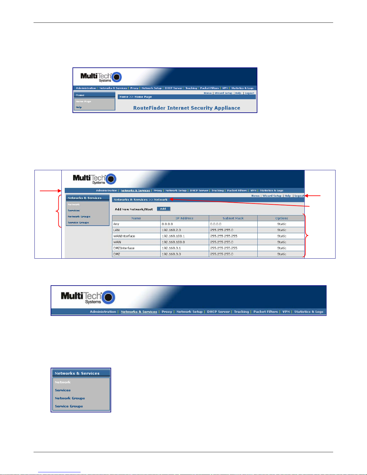
The Web Management software Home screen displays.
This software is factory-installed on your RouteFinder.
(This is a view of the top part of the Home screen.)
A description of the Web Management software continues in Chapter 4.
Before using the software, you may find the following information about navigating the screens and the
structuring of the menus helpful.
Navigating Through the Software Screens
Menu
Bar
Sub
Menu
Other
Options
Screen
Name
Input /
Display
Area
RouteFinder Menu Bar
Sub-Menu
Each item on the Menu Bar has its own sub-menu, which displays on the left side of the screen.
When you click one of the Menu Bar buttons, the first sub-menu option displays. You can choo se othe r
sub-menu screens by clicking the screen name in the sub-menu list.
This is an example of the Networks & Services sub-menu.
Multi-Tech Systems, Inc. RouteFinder RF850/860 User Guide (PN S000400E) 19
Page 20

Chapter 2 – Installation and Setup
Screen Buttons
Home The main screen.
Wizard Setup Change passwords and quickly set up your RouteFinder with the basic configuration that
will set it up as a firewall.
Help Describes what to do on each screen.
Logout Logout and return to the login screen.
Menus and Sub-Menus
Administration Networks &
Services
System Setup
SSH
SNTP Client
Administrative Access
Networks
Services
Network Groups
Service Groups
Change Root
Password
Site Certificate
License Key
Intrusion Detection
Tools
System Scheduler
Factory Defaults
User Authentication
Local Users
Radius & SAM
Version Information
Proxy Network
Setup
HTTP Proxy
Custom Filters
SMTP Proxy
SMTP SPAM Filtering
POP3 Proxy
POP3 SPAM Filtering
Advanced
Configurations
SOCKS Proxy
DNS Proxy
Interface
PPP
PPPoE
DHCP Client
Dynamic
DNS
Routes
Masquerading
SNAT
DNAT
Load
Balancing
High
Availability
Restart
Shutdown
Tracking Packet Filters VPN Statistics & Logs
Accounting
Update Services
Backup
Version Control
Packet Filter
Rules
ICMP
Advanced
Enable/Disable
Log
QoS
IPSec
X.509 Certificates
IPSec Bridging
PPTP
Uptime
Hardware
Networks
Interfaces
SMTP Proxy
Accounting
Self Monitor
IPSec
PPTP
Packet Filter
Port Scans
View Logs
HTTP Access
DHCP
SMTP Virus Quarantine
POP3 Virus Quarantine
SMTP Spam Quarantine
Administrative Authentication
Log
QoS
DDNS
DHCP Server
Subnet Settings
Fixed
Addresses
Multi-Tech Systems, Inc. RouteFinder RF850/860 User Guide (PN S000400E) 20
Page 21
Chapter 3 – Configuration Using Web Management Software
Chapter 3 – Configuration Using Web
Management Software
Initial Configuration Step
Set Up Your Time Zone
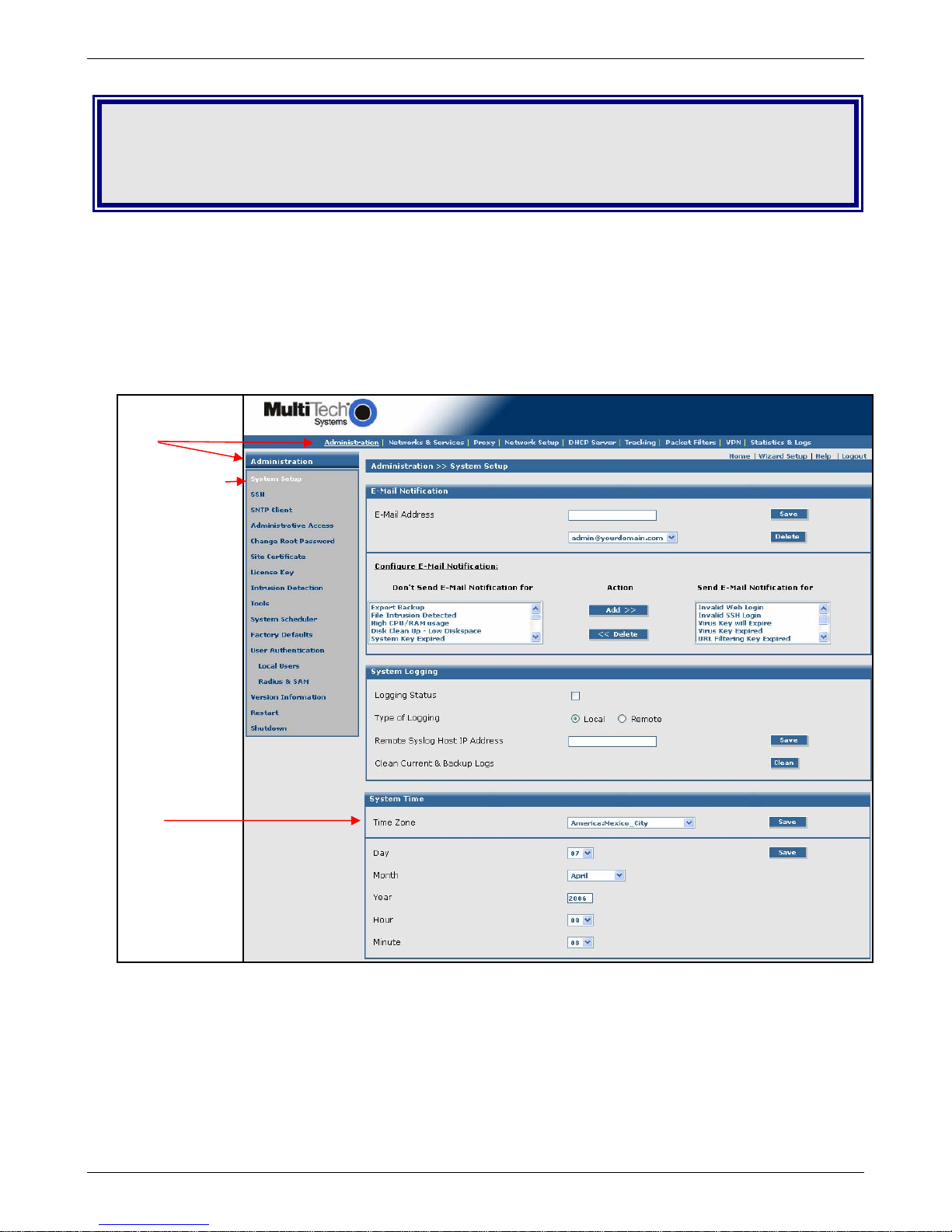
• Click Administration on the Menu Bar. The System Setup screen displays.
• Set the following:
• Set System Time by selecting your Time Zone
• Set the current Day, Month, Year, Hour, and Minute
Administration
System Setup
Submenu and first
screen listed on
the submenu
(System Setup)
display when you
click on your
Menu choice
(Administration)
System Time
Multi-Tech Systems, Inc. RouteFinder RF850/860 User Guide (PN S000400E) 21
Page 22
Chapter 3 – Configuration Using Web Management Software
Second Configuration Step – Using the Wizard Setup
Using the Wizard Setup is a quick way to enter the basic configuration parameters to allow communication
between the LAN’s workstation(s) and the Internet as shown in the example below.
Important Note: An initial configuration must be completed for each type of RouteFinder functions: firewall
configuration, LAN-to-LAN configuration, a LAN-to-Remote Client configuration.
Note about License Agreements: It is suggested that you read the legal information and license agreements
before beginning the configuration. This information can be found in the RouteFinder User Guide on the
RouteFinder CD.
RouteFinder Initial Configuration
Multi-Tech Systems, Inc. RouteFinder RF850/860 User Guide (PN S000400E) 22
Page 23
Chapter 3 – Configuration Using Web Management Software
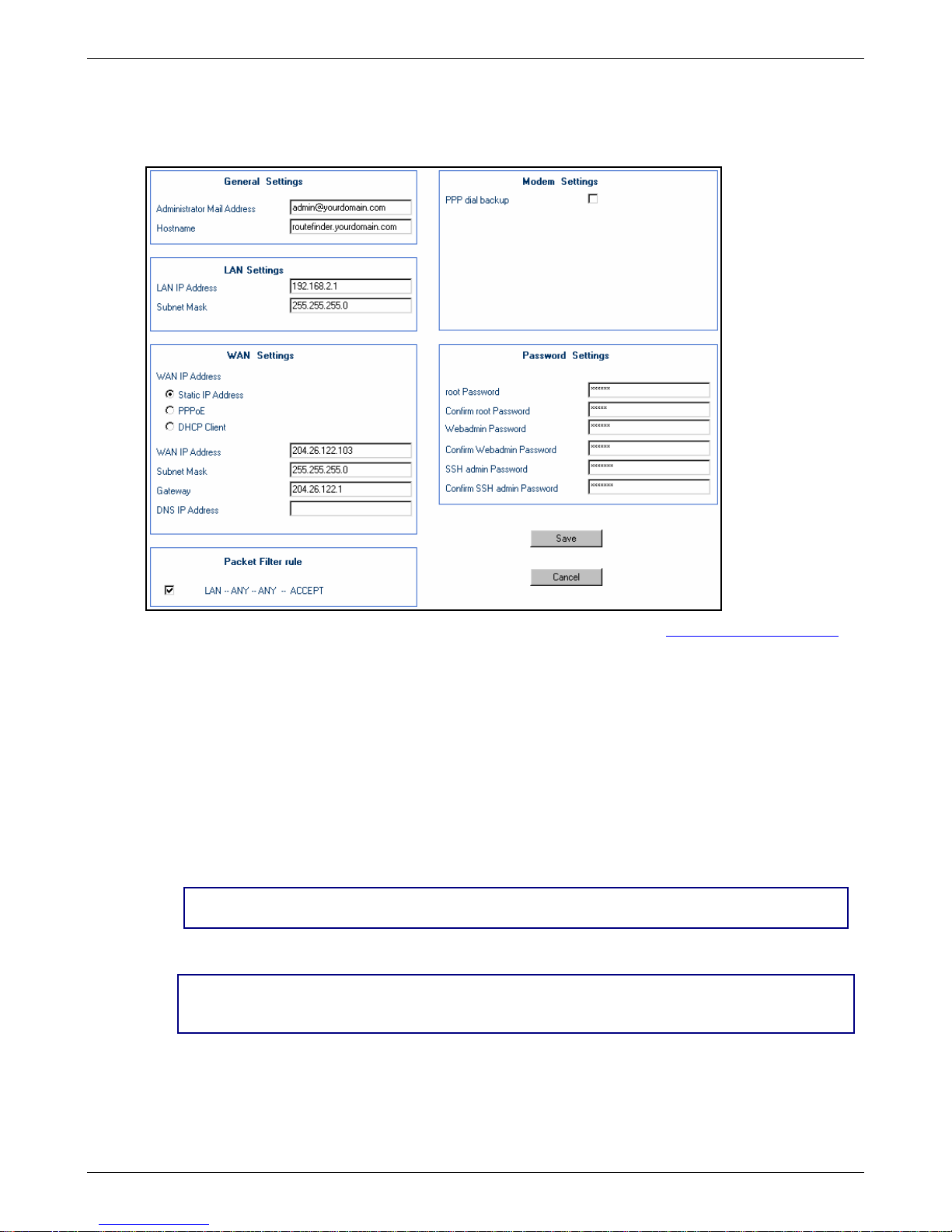
The Wizard Setup Screen – Configuration Example
Click on the Wizard Setup button located under the Menu Bar. The Wizard Setup screen displays. The screen
establishes the firewall setup and can be used to enter initial data for other setups.
1. Enter your Administrator Email Address (can be anything). Example: admin@yourdomain.com
2. Enter your Hostname for the RouteFinder (can be anything).
Example: RouteFinder.domainname.com
3. LAN IP Address and Subnet Mask def ault into the fields. These should be acceptable for your site.
4. Enter the WAN IP Address. This is the PUBLIC STATIC IP address.
Set this option based on information provided by your ISP. Example: 204.26.122.103
5. Change the Gateway IP address. This is the IP address of the router that connects to the Internet.
Example: 204.26.122.1
6. Place a checkmark in the Packet Filter Rule LAN-ANY-ANY-ACCEPT box to enable the rule.
7. Change Password Settings as appropriate for your network. It is highly recommended that you
change all default passwords. Do not leave them at the defaults for security reasons.
8. Click Save to save the settings you just entered.
9. The following message displays. Click OK to close the message box and save your changes.
Click OK to save the changes. Please be patient. Setup will take a few minutes to implement
the changes. Do not close the Browser.
Click OK to close the message box and save your changes.
10. One more message displays. Note that saving your settings will take 1-2 minutes.
Please do not close the browser. Server is saving the values. After a few minutes you will be
redirected to the new IP address. If you are not redirected, change the address in the location
bar to 192.168.2.1.
11. Test your workstation to see that it can access the Internet. If a connection is established, then the
settings have been entered correctly.
Your Basic Configuration Is Now Complete.
Multi-Tech Systems, Inc. RouteFinder RF850/860 User Guide (PN S000400E) 23
Page 24
Chapter 4 – Configuration Examples
Chapter 4 – Configuration Examples
These examples show how to configure the RouteFinder using the entire Web Management software program.
The Wizard Setup utility provides a basic firewall connection, while the Web Management sof t ware allows you to
configure VPN features, management features, and other options (see the menu outline in Chapter 2).
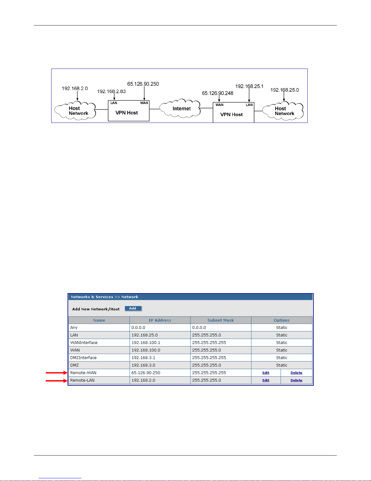
Example 1 – Setup Two RouteFinders
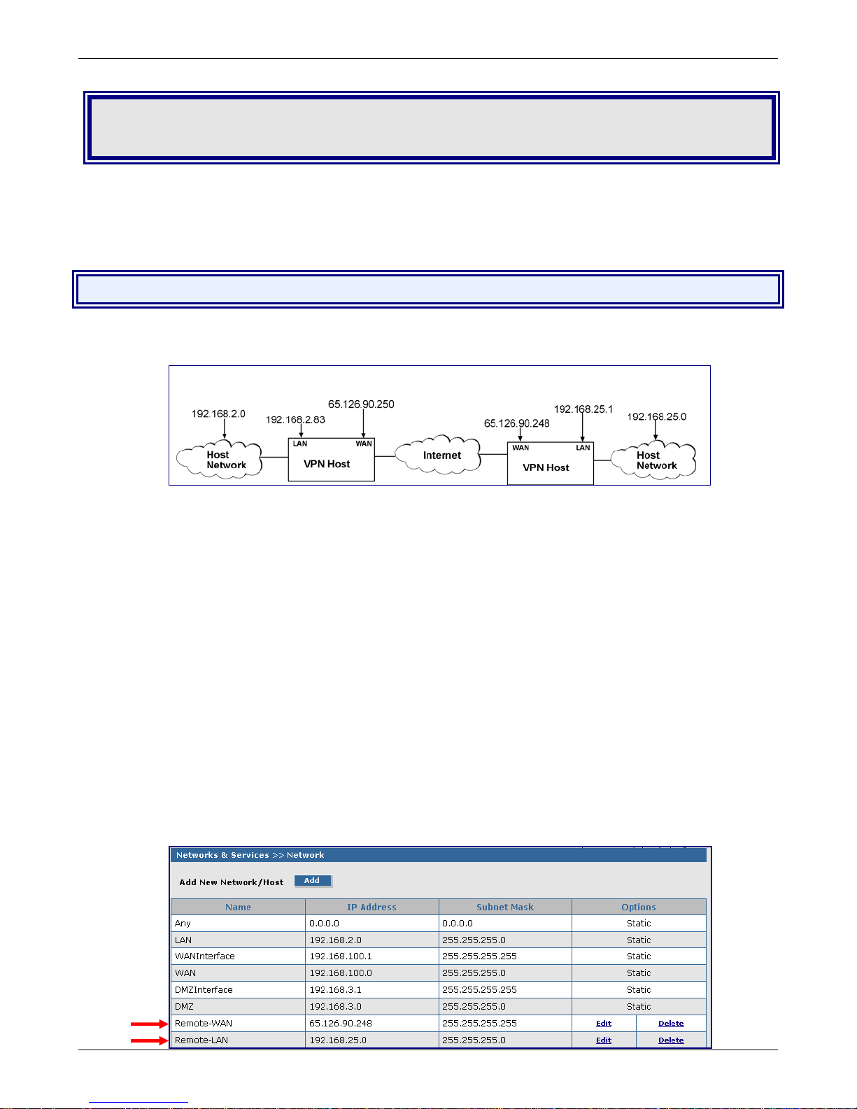
The example can be used for a LAN-to-LAN (branch office) setup. It requires two RouteFinders - one in the
home office and one in the remote branch office and requires additional parameters beyond the Wizard Setup to
be entered.
Side A Side B
RouteFinder Setup – Side A
Networks & Services > Networks Setup
1. Log in to your RouteFinder software and go to Net works & Services > Network Configuration
screen.
2. Click the Add button to open the fields for entering your network information.
3. Create a new network name for the Remote WAN by entering a Name, IP Address, and
Subnet Mask. For this example, enter the following:
Name: Remote-WAN
IP Address: 65.126.90.248
Subnet Mask: 255.255.255.255
4. Create a new network name for the Remote LAN by entering a Name, IP Address, and Subnet
Mask. For this example, enter the following:
Name: Remote-LAN
IP Address: 192.168.25.0
Subnet Mask: 255.255.255.0
5. Click Add to add the network to the li st.
Multi-Tech Systems, Inc. RouteFinder RF850/860 User Guide (PN S000400E) 24
Page 25
Chapter 4 – Configuration Examples
Example 1, Side A
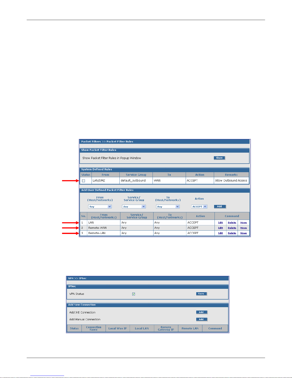
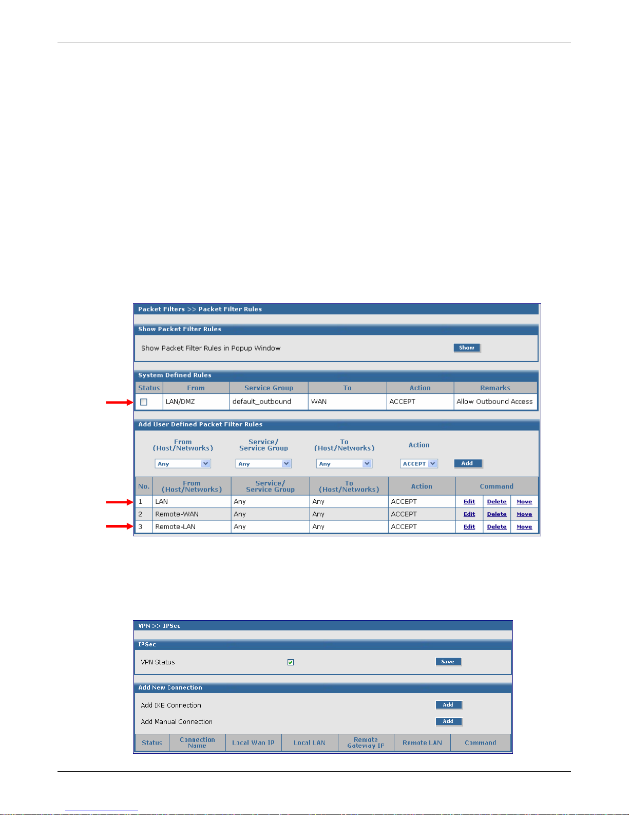
Packet Filters > Packet Filter Rules
1. Go to the Packet Filters > Packet Filter Rules screen to set the VPN client tunnel rights. The
Packet Filter rights established on this screen give the client access across the tunnel to your
host network.
2. In the System Defined Rules section, uncheck the Status box, if a check mark is present when
setting up User Defined Rules.
3. In the Add User Defined Packet Filter Rules section, click on From (Host/Networks) and select
the network to be allowed.
4. In this example, select Remote-WAN.
5. If you are not restricting the type of Service, select Any.
6. If you are not restricting any Network. Click on To (Host/Network), select Any.
Notes:
• If the client is dynamic (unknown), set up a Remote-WAN Any Any ACCEPT filter to allow any
network to come in.
• You might want to add LAN Any Any ACCEPT to the User Defined Packet Filter Rules. If you
want this rule to be in the first position so that it takes precedence over the VPN-Client rule,
select the Move command, and move this rule to the first position.
VPN Setup
1. Go to the VPN > IPSec screen.
2. Click the VPN Status check box to enable IPSec. Then click the Save button.
3. Select Add IKE Connection by clicking the corre spo nding Add button.
Multi-Tech Systems, Inc. RouteFinder RF850/860 User Guide (PN S000400E) 25
Page 26
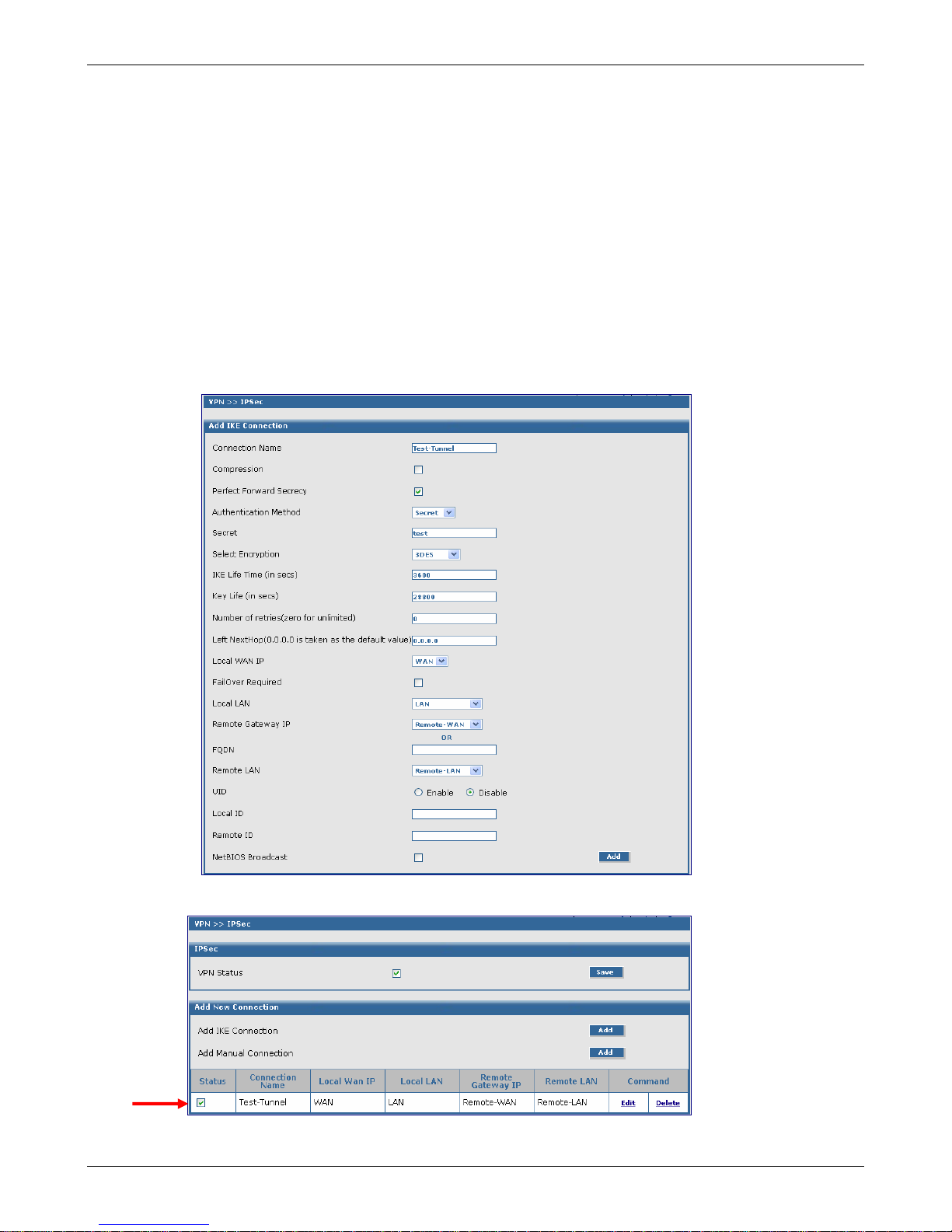
Chapter 4 – Configuration Examples
Example 1, Side A
VPN Setup (Continued)
The Add IKE Connection screen displays. All settings can be left at the default unless otherwise
indicated:
1. Connection Name: Enter in the name of the VPN tunnel you want to create.
Example: Test-Tunnel
2. Secret: Enter a Secret password (which has to match on both ends of the tunnel). For this
example, enter test.
3. Select Encryption: Select 3DES.
4. Local WAN IP: Select WAN.
5. Local LAN: Select LAN.
6. Remote Gateway IP: Select Remote-WAN. (select ANY if unknown)
7. Remote LAN: Select Remote-LAN.
8. Click the Save button to save your tunnel.
The VPN > IPSec Status screen displays; this time showing the newly-created VPN tunnel.
Important Note:
Make sure to check the Status box for this VPN tunnel in order to activate it.
Multi-Tech Systems, Inc. RouteFinder RF850/860 User Guide (PN S000400E) 26
Page 27
RouteFinder Setup – Side B
Networks & Services > Network
1. Log in to your RouteFinder software and go to Net works & Services > Network Configuration
2. Click the Add button to open the fields fo r entering your network information.
3. Create a new network name for the Remote LAN by entering a Name, IP Address, and Subnet
4. Click Add to add the network to the li st.
5. Create a new network name for the Remote WAN by entering a Name, IP Address, and
6. Click Add to add the network to the li st
Note: The same address/mask pair should not be prese nt in the current list displayed on the
screen.
Side A Side B
screen.
Mask. For this example, enter the following:
Name: Remote-LAN
IP Address: 192.168.2.0
Subnet Mask: 255.255.255.0
Subnet Mask. For this example, enter the following:
Name: Remote-WAN
IP Address: 65.126.90.250
Subnet Mask: 255.255.255.255
Chapter 4 – Configuration Examples
Example 1, Side B
Multi-Tech Systems, Inc. RouteFinder RF850/860 User Guide (PN S000400E) 27
Page 28
Chapter 4 – Configuration Examples
Example 1, Side B
Packet Filters > Packet Filter Rules
1. Go to the Packet Filters > Packet Filter Rules screen to set the VPN client tunnel rights. The
Packet Filter rights established on this screen give the client access across the tunnel to your
host network.
2. In the System Defined Rules section, uncheck the Status box, if a check mark is present when
adding User Defined Packet Filters Rules.
3. In the Add User Defined Packet Filter Rules section, click on From (Host/Networks) and select
the network to be allowed.
In this example, select Remote-LAN.
4. If you are not restricting the type of service, select Any.
5. If you are not restricting what network. Click on To (Host/Network), select Any.
Notes:
• If the client is dynamic (unknown), set up a Remote-LAN Any Any ACCEPT filter to allow any
network to come in.
• You will need to add LAN Any Any ACCEPT to the User Defined Packet Filter Rules. If you
want this rule to be in the first position so that it takes precedence over the VPN-Client rule,
select the Move command, and move this rule to the first position.
VPN Setup
1. Go to the VPN > IPSec screen.
2. Click the VPN Status check box to enable IPSec. Then click the Save button.
3. Select Add an IKE Connection by clicking the correspondi ng Add button.
Multi-Tech Systems, Inc. RouteFinder RF850/860 User Guide (PN S000400E) 28
Page 29
Chapter 4 – Configuration Examples
Example 1, Side B
VPN Setup (Continued)
The Add an IKE Connection screen displays. All settings can be left at the default unless otherwise
indicated:
1. Connection Name: Enter in the name of the VPN tunnel you want to create. Example: Test-
Tunnel.
2. Secret: Enter the Secret password (which has to match on both en ds of the tunnel). For this
example, enter test.
3. Select Encryption: Select 3DES.
4. Local WAN IP: Select WAN
5. Local LAN: Select LAN
6. Remote Gateway IP: Select Remote-WAN (Select Any if unkno wn)
7. Remote LAN: Select Remote-LAN.
8. Click the Save button to save your tunnel.
The VPN > IPSec Status screen displays; this time showing the newly-created VPN tunnel.
Important Note:
Make sure to check the Status box for this VPN tunnel in order to activate it.
Multi-Tech Systems, Inc. RouteFinder RF850/860 User Guide (PN S000400E) 29
Page 30
Chapter 4 – Configuration Examples
Example 2, Side A
Example 2 – Set Up Two RouteFinders Behind a NAT
Device
Side A Side B
RouteFinder Setup – Side A
Networks & Services > Networks
1. Login to your RouteFinder and go to the Networks & Services > Network Configuration
screen.
2. Click the Add button to open the fields fo r entering the network information.
3. Create a new network name for the RF850-LAN by entering the Name, IP Address, and
Subnet Mask. For this example, enter the following:
Name: RF850-LAN
IP Address: 192.168.25.0
Subnet Mask: 255.255.255.0
4. Click the Add button to add the new network to the list.
5. Create a new network name for the RF850-WAN by entering the Name, IP Address, and
Subnet Mask. For this example, enter the following:
Name: RF850-LAN
IP Address: 65.126.90.248
Subnet Mask: 255.255.255.255
6. Click the Add button to add the new network to the list.
Multi-Tech Systems, Inc. RouteFinder RF850/860 User Guide (PN S000400E) 30
Page 31

Chapter 4 – Configuration Examples
Example 2, Side A
Packet Filters > Packet Filter Rules
1. Go to the Packet Filters > Packet Filters Rules screen to set the VPN client tunnel rights. T he
Packet Filter rights established on this screen give the client access across the tunnel to your
host network.
2. In the System Defined Rules section, uncheck the Status box, if a check mark is present.
3. In the Add User Defined Packet Filter Rules section, click on From (Host/Networks) and select
the network to be allowed.
In this example, select RF850-LAN.
4. If you are not restricting the type of service, select Any.
5. If you are not restricting what network. Click on To (Host/Network), select Any.
Notes:
• If the client is dynamic (unknown), set up an RF850-LAN Any Any ACCEPT filter to allow any
network to come in.
• You might want to add LAN Any Any ACCEPT to the User Defined Packet Filter Rules. If you
want this rule to be in the first position so that it takes precedence over the VPN-Client rule,
select the Move command, and move this rule to the first position.
VPN Setup
1. Go to the VPN > IPSec screen.
2. Click on the VPN Status check box to enable IPSec. Then click t he Save button.
3. Select Add an IKE Connection by clicking the correspondi ng Add button.
Multi-Tech Systems, Inc. RouteFinder RF850/860 User Guide (PN S000400E) 31
Page 32

Chapter 4 – Configuration Examples
Example 2, Side A
VPN Setup (Continued)
The Add IKE Connection screen displays. All settings can be left at the default unless otherwise
indicated:
1. Connection Name: Enter a name for the VPN tunnel you want to create. For this example,
enter Behind-NAT.
2. Secret: Enter the Secret password (which has to match on both en ds of the tunnel). For this
example, enter test.
3. Select Encryption: Select 3DES.
4. Local WAN IP: Select WAN.
5. Local LAN: Select LAN.
6. Remote Gateway IP: Select RF850-WAN.
7. Remote LAN: Select RF850-LAN.
8. UID: Click the Enable button (must be enabled when using NAT).
9. Local ID: Enter the local security gateway ID (required when using NAT). For this example,
enter 192.168.2.8
10. Remote ID: Enter the remote security gateway ID (required when using NAT). For this example,
enter 65.126.90.248
11. Click the Add button to save your tunnel.
The VPN > IPSec Status screen displays; this time showing the newly-created VPN tunnel.
Important Note:
Make sure to
check the
Status box for
this VPN tunnel
in order to
activate it.
Multi-Tech Systems, Inc. RouteFinder RF850/860 User Guide (PN S000400E) 32
Page 33

Chapter 4 – Configuration Examples
RouteFinder Setup – Side B
Side A Side B
Example 2, Side B
Network & Services > Network
1. Log into your RouteFinde r and go to the Networks & Services > Network
Configuration screen.
2. Click the Add button to open the fields for entering your network information.
3. Create a new network name for the RF850-WAN by entering the Name, IP Address,
and Subnet Mask. For this example, enter the following:
Name: RF850-WAN
IP Address: 65.126.90.250
Subnet Mask: 255.255.255.255
4. Click the Add button to add the new network to the list.
5. Create a new network name for the RF850-LAN by entering the Name, IP Address,
and Subnet Mask. For this example, enter the following:
Name: RF850-LAN
IP Address: 192.168.10.0
Subnet Mask: 255.255.255.0
6. Click the Add button to add the new network to the list.
Multi-Tech Systems, Inc. RouteFinder RF850/860 User Guide (PN S000400E) 33
Page 34

Packet Filters > Packet Filter Rules
1. Go to the Packet Filters > Packet Filter Rules screen to set the VPN client tunnel rights. The
Packet Filter rights established on this screen give the client access across the tunnel to your
host network.
2. In the System Defined Rules section, uncheck the Status box, if a check mark is present.
3. In the Add User Defined Packet Filter Rules section, click on From (Host/Networks) and select
the network to be allowed. In this example, select RF850-WAN.
4. If you are not restricting the type of service, select Any.
5. If you are not restricting what network. Click on To (Host/Network), select Any.
Notes:
• If the client is dynamic (unknown), set up an RF850-WAN Any Any ACCEPT filter to allow any
network to come in.
• You might want to add LAN Any Any ACCEPT to the User Defined Packet Filter Rules. If you
want this rule to be in the first position so that it takes precedence over the VPN-Client rule,
select the Move command, and move this rule to the first position.
Chapter 4 – Configuration Examples
Example 2, Side B
VPN Setup
1. Go to the VPN > IPSec screen.
2. Click on the VPN Status check box to enable IPSec. Then click t he Save button.
3. Select Add an IKE Connection by clicking the correspondi ng Add button.
Multi-Tech Systems, Inc. RouteFinder RF850/860 User Guide (PN S000400E) 34
Page 35

Chapter 4 – Configuration Examples
Example 2, Side B
VPN Setup (Continued)
The Add IKE Connection screen displays. All settings can be left at the default unless otherwise
indicated:
1. Connection Name: Enter the name of the VPN tunnel you want to create. For this example,
enter Behind-NAT.
2. Secret: Enter the Secret password (which has to match on both en ds of the tunnel). For this
example, enter test.
3. Select Encryption: Select 3DES.
4. Local WAN IP: Select WAN.
5. Local LAN: Select LAN.
6. Remote Gateway IP: Select RF850-WAN.
7. Remote LAN: Select RF850-LAN.
8. UID: Click the Enable button (must be enabled when using NAT).
9. Local ID: Enter the local security gateway ID (required when using NAT). For this example,
enter 65.126.90.248
10. Remote ID: Enter the remote security gateway ID (required when using NAT). For this example,
enter 192.126.2.8
11. Click the Save button to save your tunnel.
The VPN > IPSec Status screen displays; this time showing the newly-created VPN tunnel.
mportant Note:
ake sure to
check the
Status box for
this VPN tunnel
in order to
activate it.
Multi-Tech Systems, Inc. RouteFinder RF850/860 User Guide (PN S000400E) 35
Page 36

Chapter 4 – Configuration Examples
A
2
4
5
Example 3
Example 3 – Remote Client-to-LAN Configuration
Using DNAT and Aliasing
Use this procedure to configure the RouteFinder with DNAT and Aliasing. This configuration allows a Windows
Remote Client to Telnet through the RouteFinder to several Windows Operating Systems located on the LAN.
Remote Client-to-LAN Configuration Using DNAT and
liasing Through the RouteFinder
1. Networks & Services > Network screen
Enter: LAN Network, 192.168.2.0, 255.255.255.0
Enter WANInterface1, 204.26.122.103, 255.255.255.255
Enter WANInterface2, 210.26.122.104, 255.255.255.255
Enter WIN2k_Pro, 192.168.2.100, 255.255.255.255
Enter WIN2k_Server, 192.168.2.11, 255.255.255.255
2. Network Setup > Interface screen
Set default gateway at 204.26.122.1
Enter a host name (example: RF860.Site-A.com)
Enter Network Cards: (Cards 1 & 3 are defaulted)
Card 1: LAN (eth0), 192,168.2.1, 255.255.255.0
Card 2: WAN (eth1), 204.26.122.103,
55.255.255.0
Card 3: DMZ (eth2), 192.168.3.1
3. Network Setup > Interface > IP Aliases section
Interface: Select LAN(eth0)
Enter IP Address: 204.26.122.104
Enter Net Mask: 255.255.255.255
Interface: Select: Select WAN (eth1)
Enter IP Address: 204.26.122.105
Enter Net Mask: 255.255.255.255
. Network Setup > DNAT screen
Enter two profiles:
Pre DNAT Network: Select WANInterface1
Pre DNAT Service: Select Telnet
Post DNAT IP Address: Select Win2k_Pro
Post DNAT Service: Select Telnet
Pre DNAT Network: Select WANInterface2
Pre DNAT Service: Select Telnet
Post DNAT IP Address: Select Win2k_Server
Post DNAT Service: Select Telnet
. Packet Filters > Packet Filter Rules screen
Add User Defined Packet Filter Rules
LAN – ANY – ANY – Accept
ANY – Telnet – Win2k_Pro – Accept
ANY – Telnet – Win2k_Server – Accept
Multi-Tech Systems, Inc. RouteFinder RF850/860 User Guide (PN S000400E) 36
Page 37

Chapter 4 – Configuration Examples
Example 4
Example 4 – Client-to-LAN Configuration Using PPTP
Tunneling
Use this procedure to configure the RouteFinder as a PPTP server for VPN Remote Client Access. This is also
known as the PPTP Roadwarrior configuration.
Note: IPX and Netbeui are not supported when using PPTP tunneling.
Remote Client-to-LAN Configuration Using PPTP
Tunneling Through the RouteFinder
1. Networks & Services > Network screen
Enter: LAN Network, 192.168.2.0, 255.255.255.0
Enter: PPTP-Pool, 192.168.2.240, 255.255.255.240
2. Network Setup > Interface screen
Set default gateway at 204.26.122.1
Enter a host name (example: RF860.Site-A.com)
Enter Network Cards: (Cards 1 & 3 are defaulted)
Card 1: LAN (eth0), 192,168.2.1, 255.255.255.0
Card 2: WAN (eth1), 204.26.122.103,
255.255.255.0
Card 3: DMZ (eth2), 192.168.3.1
3. Packet Filters > Packet Filter Rules screen
Add User Defined Packet Filter Rules
LAN – ANY – ANY – Accept
4. VPN > PPTP screen
Check the PPTP Status box
Encryption Strength: Select 40 or 128
Select Remote Address: Select PPTP-Pool
Click the Save button. The addresses and range
display
Authentication Type: Select Local
Username: Enter user name (example: roadwarrior)
Password: Enter user password (example:1o2t3t4t)
Click the Add button.
Checking the Tunnel
After setting up your RouteFinder, you can check the status of your VPN tunnel by clicking on Statistics & Logs
and going to the IPSec Live Log. You will see the connection up and running (if connected), and you will see
the statistics related to the data being sent across the tunnel.
Multi-Tech Systems, Inc. RouteFinder RF850/860 User Guide (PN S000400E) 37
Page 38

Chapter 5 – URL Categorization
Chapter 5 – URL Categorization
The Universal Resource Locator (URL) Categorization License Key allows you to set up a URL database that
limits clients’ access to places on the Internet by blocking sites you do not want accessed. In other words, you
can deny users access to various categories of Web sites you select.
Important Settings
• The RouteFinder must be connected to the Internet for the URL License to be activated.
• With the HTTP proxy functioning in transparent mode, clients are unaware that their Internet requests
are being transferred through an HTTP proxy.
Setting Up HTTP Proxy and URL Filtering
1. Click Proxy from the Menu bar. The HTTP Proxy screen displays.
Notes About the HTTP Proxy Screen:
• When this screen initially displays, only the HTTP Proxy Status field, its checkbox and Save
button can be seen.
• More parts of the HTTP Proxy screen display after clicking Status and Save. Also, the URL
Categorization section and the Authentication section display.
• After clicking and saving URL Filter and User Authentication, more parts to these screen
display as shown below.
• If you check and Save Transparency, User Authentication is not available. The Transparency
option is not shown on this screen since it was not checked and User Authentication was
selected.
Multi-Tech Systems, Inc. RouteFinder RF850/860 User Guide (PN S000400E) 38
Page 39

Chapter 5 – URL Categorization
2. On the HTTP Proxy > HTTP screen (see previous page), check the Status box and click Save.
Important Note: Status must be checked before you can enter and activate your URL Categorization
License Key.
Note About URL License Key: The URL License number must be entered on the Administration >
License Key screen before the URL Categorization section of this screen displays. The 30-day free trial
key number is located on the bottom of the RouteFinder chassis and on the front of the Quick Start
Guide.
3. Changing Status for the LAN:
On the HTTP Proxy > HTTP screen (see previous page), check the Add button across from Select
Networks (allowed / denied). The HTTP Non-Transparent Networks screen displays:
Click Change Status for LAN. The Change Status for LAN screen displays. Click Change and select
Allowed from the drop down list box:
This screen shows LAN status changed to Allowed:
4. URL Filtering:
On the HTTP Proxy > HTTP screen in the URL Categorization section, check the URL Filter box and
click Save. These fields are now visible:
URL Categories (allowed / filtered) and
Networks / Hosts to bypass URL Filtering.
Multi-Tech Systems, Inc. RouteFinder RF850/860 User Guide (PN S000400E) 39
Page 40

5. URL Categories (Allowed/Filtered)
Click Edit for URL Categories (Allowed/Filtered). The following URL Categories screen displays. This
screen allows you to choose Web site that you want blocked/filtered from users.
Use the Filter and Allow buttons to move a URL Category from the URL Categories Allowed list to
the URL Categories Filtered or back to the allowed list.
When you are finished organizing the categories, click the Back button to go back to the HTTP >
HTTP Proxy main screen.
Chapter 5 – URL Categorization
Testing Filtering Using Get URL Catgory
To test the filtering, type a URL in the http:// box and click the Go button. This will test the URL to see
if it is allowed or blocked.
Note: You can also test a site through your browser by entering a Web address that you feel should
be blocked by the filter through one of the categories you had chosen or a category preset by the URL
software. For instance, if you selected the Finance and Investment category to be filtered, try to
access www.etrade.com
stating the status of this Web site.
Important: The sites listed in the Favorites box of the browser will not be blocked unless the cache is
emptied in the browser.
6. Networks / Hosts to bypass URL Filtering
Return to the Proxy > HTTP Proxy main screen. In the URL Categorization section, click the
Networks / Hosts to bypass URL Filtering. The Networks/Hosts to bypass screen displays.
• Select a network/host and click the Add button to add it to the Networks/Hosts to bypass URL
Filtering. These networks/hosts will be able to access all sites; URL Category based filtering will
not happen for these networks/hosts.
• If you decide you do not want one or more of the networks/hosts bypassing the filter, select the
name and click the Delete button. The name moves back into the Available Net works/Host box.
. This site should be blocked. A message displays under the URL address
Multi-Tech Systems, Inc. RouteFinder RF850/860 User Guide (PN S000400E) 40
Page 41

Chapter 6 – RouteFinder Software
Chapter 6 – RouteFinder Software
This chapter describes each screen and its function in the RouteFinder software. The aim of the administrator in
setting the options in the software should be to let as little as possible and as much as necessary through the
RouteFinder, for both incoming as well as outgoing connections.
Note: If you have not done so already, plan your network and decide which computers are to have access to
various services. This simplifies the configuration and saves you a lot of time that you would otherwise need for
corrections and adjustments.
Menu Bar
The Menu bar provides the organization of this chapter.
Menu Bar
Logout
Important Note About Logout
Logout Closes the Software Program and Saves Settings
The best way to exit WebAdmin is to choose Logout. This will save all your current settings. The browser
connection is terminated and you are returned to the Login screen. Note that clicking the browser’s Back
button will not effectively return you to the previous menu or directory at this point.
If you close the browser while configuring the RouteFinder, the last session sta y s active until the end of the
time-out, and no new administrator can log in. The timeout period is set at Administration >
Administrative Access > Time Before Automatic Disconnect.
Multi-Tech Systems, Inc. RouteFinder RF850/860 User Guide (PN S000400E) 41
Page 42

Chapter 6 – RouteFinder Software
Administration > System Setup
Administration
Administration > System Setup
In Administration, you can set the RouteFinder general system-based paramet ers.
A Note About This Screen: When Logging Status is not checked, the section of the screen Configure Logging
does not display.
Email Notification
Email Address
Enter the Email Address of the administrator who will receive the email notifications. Click Save.
You can delete the entry and change it at any time, if desired.
At least one email address must be entered in this field.
Multi-Tech Systems, Inc. RouteFinder RF850/860 User Guide (PN S000400E) 42
Page 43

Chapter 6 – RouteFinder Software
Administration > System Setup
Configure Email Notifications
Select the types of notifications that you want sent. Click the Add button. The name will then appear
in the Send Email Notification For box. You can remove a type by clicking the Delete button. The
name will then move back to the Don't Send Email Notification For box.
1. Export Backup (the backup file will be attached)
2. File Intrusion Detection (File Integrity Ch ecks and Network Intrusions)
3. High CPU/RAM Usage (Hard disk u sag e exceeding 70%)
4. Disk Clean Up – Low Diskspace
5. System Key Expired (10 days before expiry)
6. Invalid Web Login
7. Invalid SSH Login
8. Port Intrusion Detected
9. PPP backup link down
10. PPP backup link up
11. URL Filtering Server Error
12. Auto System Update
13. Virus Key Will Expire
14. Virus Key Has Expired
15. Virus Database Updated
16. URL Filtering Key Expired
17. URL Filtering Key Will Expire (10 days, 2 days, and 1 day before expiry)
18. URL Filtering Categories Updated
19. URL Categories Update Failed
20. Bayesian Database Has Reached Maximum
21. POP3 Virus Mail
22. HTTP Access Deny Reports
23. HA Synchronization
24. Backup Logs
25. High Availability Peer Status
26. Load Balancing WANLinks Status
The mail settings are saved in the server configuration. The first email ID in the list should be the
Administrator's ID, so that when the first ID is added or deleted, the session is terminated and the
Web server restarted.
System Logging
Logging Status
Check the Logging Status box to activate and enable the host to receive log messages from other
machines.
Local or Remote
Select the type of logging, either Local or Remote.
Remote Syslog Host IP Address
Enter the IP address of the Remote Syslog Host to which all log messages from the RouteFinder
will be forwarded. Click Save.
Notes:
•
The IP address is a required parameter.
• On the remote host, syslog should be invoked with the "-r" option to enable the host to receive
log messages from other machines. This is especially recommended if you wan t to collect the
log files of several systems on one host. The default setting is ’off’.
Clean Current and Backup Logs
Click Clean to delete all the current and backup system log files.
Configure Logging
Select the types of logs that you want sent. Click the Add button. The name will then appear in the
Enabled Logs box. You can remove a log by clicking the Delete button. The name will than move
back to the Disabled Logs box.
The drop down box lists: SMTP/POP3 Messages, SNTP/UUCP/FTP Messages, SMTP Debug
Messages, IPSec Debug Messages, IKE Debug Messages, Kernel Messages, Web Access
Messages, Boot Messages, Cron Messages, Daemon Messages, and PPTP Debug Messages.
Multi-Tech Systems, Inc. RouteFinder RF850/860 User Guide (PN S000400E) 43
Page 44

Chapter 6 – RouteFinder Software
Administration > System Setup
Administration > SSH
System Time
Select the system time, time zone, and current date.
Note: We do not recommend changing from summertime to wintertime and back. We suggest entering
Greenwich Mean Time (GMT), regardless of your global position, especially if you operate Virtual
Private Networks across different time zones. Changing the system time can lead to the following timewarp effects:
Forward time adjustment (winter to summertime)
The time-out for the Web Admin has expired and your session is not valid anymore.
Log information for some time periods may be missing in the time-based reports.
Most diagrams show this time period as a straight line at the height of the old value.
All the values for Accounting in this time period are 0.
Backward time adjustment (summer to wintertime)
The time-based reports already contain log information for the correspondi ng time period which, as
far as the system is concerned, comes from the future: this information is not overwritten, but is
retained.
The writing of the log files is continued from the point of time before the setback time is reached.
Most diagrams show the values of this time period as compressed.
The already-recorded data (from the future) retain their validity for the Accounting function.
The accounting files are continued when the setback time is reached again. Therefore, it is
recommended that the time should only be set once during initial configuration and later should only
be slightly adjusted. No adjustments from wintertime to summertime should be made, especially if
the collected reporting and accounting information is to be further processed.
Administration > SSH
What Is SSH
SSH (Secure Shell) is a program to use to log into another computer over a network to execute commands in a
remote machine and to move files from one machine to another. It provides strong authentication and secure
communications. SSH provides access to the firewall using an SSH channel. Access via SSH is encrypted.
Prerequisites
• For access via SSH, you need an SSH Client, which most Linux systems already include. For MS
Windows, the program PuTTY is recommended as an SSH client.
• To log into the RouteFinder with Secure Shell (SSH, Port 22), use the login user account and the
appropriate password that was set up during installation. Remember to change your password regularly!
• Networks allowed to access the RouteFinder using SSH are added on this screen; other networks can
be defined on the Networks & Services > Networks screen.
IMPORTANT: Do not delete any network in the Allowed Networks/Hosts currently in use. This will cause the
RouteFinder to shut down and you will have to manually reboot. For manual reboot instructions, see
Administration > Restart > Manual Restart.
Multi-Tech Systems, Inc. RouteFinder RF850/860 User Guide (PN S000400E) 44
Page 45

Chapter 6 – RouteFinder Software
Administration > SSH
Administration > SNTP Client
Status and SSH Port
Initially, this screen displays with Status as the only prompt. Once Status is checked and you click
Save, SSH is enabled and the other options display. The TCP port number for the SSH session is
specified in the SSH Port Number field; the default is Port 22.
SSH requires name resolution for the access protocol; otherwise, a time-out occurs with the SSH
registration. This time-out takes about one minute. During this time it seems as if the connection is
frozen or that it can’t be established. After that, the connection returns to normal without any further
delay.
Allowed Networks/Hosts
Networks allowed to access the RouteFinder through SSH can be added and deleted here. The
default Any in Allowed Networks ensures a smooth installation and allows everyone to access
SSH service.
Caution: While the default setting (Any) allows everyone to access the SSH service, we
recommend that you restrict access to the SSH service for security reasons. Yo u should delete
access from all other networks! When deleting a network, the program checks whether you are still
able to access Administration > Administrative Access from your active IP address after the
deleting procedure. If this is no longer possible, the process is not carried out. This check is carried
out for the security of the administrator and will ensure that the administrator cannot become locked
out accidentally. After completing the adjustments, it is a good idea to disable SSH access again for
security reasons.
Available Networks/Hosts: The options in the drop-down box are different when Load Balancing is
enabled.
When Load Balancing is enabled, the options are:
Any
WANLINK1 Interface
WANLINK
WANLINK2 Interface
WANLINK2
When Load Balancing is disabled, the options are:
Any
LAN
WAN
DMZ
WAN Interface
DMZ Interface
Allowed Users
Users allowed to access the RouteFinder through SSH can be added and delet ed here.
Highlight the Users you want to have access to SSH service and cl ick the Add button. Users
can be deleted from this list at any time.
Administration > SNTP Client
SNTP (Simple Network Time Protocol) is an internet protocol used to synchronize the clocks of computers on
the network. Clicking the SNTP Client check box enables the firewall to act as a SNTP client.
SNTP Client
SNTP Client
Check the SNTP Client box to activate SNTP Client.
SNTP Server Address
Enter the IP address of the SNTP Server for which the firewall will contact to synchronize its
clock. Then click the Save button.
Multi-Tech Systems, Inc. RouteFinder RF850/860 User Guide (PN S000400E) 45
Page 46

Chapter 6 – RouteFinder Software
Administration > Administrative Access
Administration > Administrative Access
The networks and hosts that are allowed to have administrative access are selected on this screen. This is a
good way to regulate access to the configuration tools.
Administrative Access - Available Networks/Hosts and Allowed Networks/Hos ts
Select the networks/hosts that will be allowed administrative access. Note that the selection box list
will include those networks you enter under Networks & Services > Networks.
You can change access by moving network/hosts names from the Available list to/from the
Allowed list. The RouteFinder will display an ERROR message if you try to delete access to a
network that would cause you to lock yourself out.
Any has been set as the default for ease of installation. ANY allows administrative access from
everywhere once a valid password is provided.
Caution: As soon as you can limit the location from which the RouteFinder is to be administ ered
(e.g., your IP address in the internal network), replace the entry ANY with a smaller network. The
safest approach is to have only one administrative PC given access to the RouteFinder. You can do
this by defining a network with the address of a single computer from the Networks and Services >
Networks screen.
Available Networks/Hosts: The options in the drop-down box are different when Load Balancing is
enabled.
When Load Balancing is enabled, the options are:
Any, WANLINK1 Interface, WANLINK, WANLINK2 Interface, WANLINK2
When Load Balancing is disabled, the options are:
Any, LAN, WAN, DMZ, WAN Interface, DMZ Interface
Multi-Tech Systems, Inc. RouteFinder RF850/860 User Guide (PN S000400E) 46
Page 47

Chapter 6 – RouteFinder Software
Administration > Administrative Access
Change Password
You should change the password immediately after initial installation and configuration, and also
change it regularly thereafter. To change the password, enter the existing password in the Old
Password field, enter the new password into the New Password field, and confirm your new
password by re-entering it into the Confirmation entry field.
Caution: Use secure passwords! For example, your name spelled backwards is not secure enough;
something like xfT35$4 is better.
Time Before Automatic Disconnect
An automatic inactivity disconnection interval is implemented for security purposes. In the Time
Before Automatic Disconnect entry field, enter the desired time span (in seconds) after which you
will be automatically disconnected from the software program if no operations take place.
After the initial installation, the default setting is 3000 seconds. The smallest possible setting is 60
seconds. If you close the browser in the middle of an open configuration session witho ut closing via
Exit, the last session stays active until the end of the time-out and no new administrator can log in.
If using SSH, you can manually remove the active session if you log into the RouteFinder as login
user via SSH. With the command SU, you become a root user and can then interrupt the current
connection with rm -f /tmp/wfelock.
Administrative Access HTTPS Port
This field is used for setting the HTTPS port for Web administration. After setting the HTTPS port,
the connection is terminated. The browser settings have to be changed for the new port number
before starting the next session.
By default, port 443 is configured for HTTPS sessions. The value of the port number should lie
between 1 and 65535. Well known ports and ports already used by the firewall are not allowed.
If you want to use the HTTPS service for other purposes (e.g., a diversion with DNAT), you must
enter a different TCP port for the interface here. Possible values are 1-65535, but remember that
certain ports are reserved for other services. We suggest you use ports 440-450. To have
Administrative Access after the change, you must append the port to the IP address of the
ROUTEFINDER separated by a colon (e.g., https://192.168.0.1:445
Administrative Access HTTP Port
Check this box if you want to use HTTP to access the RouteFinder’s software. This is less secure,
but it is faster when performing administrative tasks. Click Save.
Logo and Version on Logon Page
Check this box if you want the logo and version number to display on the logon page. Click Save.
Administrative Authentication Log
Log Successful Attempts
If you check this box, the successful login attempts at the RouteFinder's administrative access
interface will be recorded and displayed on the Statistics & Logs > Administrativ e
Authentication screen.
Log Failed Attempts
If you check this box, the failed login attempts at the RouteFinder's administrative access
interface will be recorded and displayed on the Statistics & Logs > Administrativ e
Authentication screen.
).
Administration > Change Root Password
Use this screen to change the root password of the RouteFinder. Enter the existing password in the Old
Password field, enter the new password into the New Password field, and confirm the new password by re entering it in the Confirmation field. The default password is root.
Multi-Tech Systems, Inc. RouteFinder RF850/860 User Guide (PN S000400E) 47
Page 48

Chapter 6 – RouteFinder Software
Administration > Site Certificate
Administration > Site Certificate
Public keys are used as the encryption algorithm for security systems. For the validity of public keys, certificates
are issued by a Certificate Authority that certifies the person or the entity is authenticated and that the present
public key belongs to that same person or entity. On this screen, enter server certificate information, which the
firewall needs to authenticate itself to your browser. After saving the settings, the browser’s security information
settings have to be cleared.
Certificate Information
Country Code
Use the default (United States) or change to the country of operation.
State or Region
Enter the state, province, region, etc. of operation.
City
Enter the city name.
Company
Enter the company name.
Organization Unit
Type the organizational unit (e.g., Sales & Marketing).
Contact Email
Type the email address of the contact for RouteFinder certificate data (e.g., the RouteFinder
administrator) over the default (myname@mydomain.com).
Firewall Host Address
Enter the RouteFinder‘s host address. Use the same address that you will use to open the
Administration Access interface. It can be one of the RouteFinder IP addresses.
• Example: If you access Administration Access with https://192.168.10.1
Address must also be 192.168.10.1. If you access Administration Access with a DNS
host name (e.g., https://MultiAccess Communications Server.mydomain.com
this name instead.
• Note: The Host Address field MUST
use in your browser to open Administration Access.
Click Save
The browser will reconnect to the VPN. At the security Alert screen, click View Certificate.
Then click Install Certificate if you have not previously installed it:
Install the Certificate into the Trusted Root Certification Authorities Store
1. When the first screen displays, click the Install Certificate button.
2. On the Welcome to Certificate Import Wizard screen, click the Next button.
3. On the Certificate Manager Import Wizard screen, click Next. You can elect to have the
certificate automatically placed into a directory or you can Browse and choose your own
directory. If you elect to place all certificates into a selected location, follow the onscreen prompts for Select Certificate Store, Physical Stores, and Root Stores.
4. When the certificate has been added to the Root Store, the Compl eting the Certificate
Manager Import Wizard displays. Click Finish.
, the Host
), then use
match the host Address or IP Address that you
Multi-Tech Systems, Inc. RouteFinder RF850/860 User Guide (PN S000400E) 48
Page 49

Chapter 6 – RouteFinder Software
Administration > License Key
Administration > License Key
The system license key, virus scanner license key, and the URL Categorization engine licen se key can be
configured from this screen.
Notes:
• Each RouteFinder ships with a unique individual system license key. It is a 20-digi t code that is
provided on the RouteFinder CD.
• Each RouteFinder ships with a URL Categorization License Key along with a 30-day free trial of the
content filtering software. It is provided on the RouteFinder CD.
• The AntiVirus key can be purchased from Multi-Tech Sales Support.
License
Click the Open button for the desired license key. The Enter License Key screen displays.
System License Key
Enter the license key number assigned to your RouteFinder and click Sav e. When you have
entered the License Key accurately, the Enter System License Key screen is re-displayed.
Important:
• The license key number is a 20-digit alphanumeric entry; the letters must all be in upper
case.
• If you enter your license key number incorrectly, the message Error: License is invalid is
displayed. Check the license key number and re-enter it. One common entry error is
mistaking a 0 (zero) for an o (the letter O). Another entry error is entering lower case letters
or symbols.
• The License Key number is tied to and tracked with your RouteFinder‘s serial number.
• Whenever you require additional licenses, you must first provide Multi-Tech with your
current License Key and serial number information in order for us to update your
RouteFinder.
• With a valid License Key, you are entitled to use Multi-Tech’s Update service and support.
AntiVirus License Key
The AntiVirus license key can be purchased from Multi-Tech sales support. Enter the license
key.
URL Categorization Key
A 30-day trial license key is included with your RouteFinder when it ships, but you must enter
the license key to activate the feature. The 15-digit key number is included on the serial label
located on the front page of the Quick Start Guide and on the bottom of the RouteFinder
chassis.
Multi-Tech Systems, Inc. RouteFinder RF850/860 User Guide (PN S000400E) 49
Page 50

Chapter 6 – RouteFinder Software
Administration > Intruder Detection
Administration > Intrusion Detection
The Intrusion Detection mechanism notifies the administrator if there has been any tampering with the files on
the server.
Network Options Available When Load Balancing is Enabled:
Intrusion Detection
Enable File Integrity Check
Check the box to enable File Integrity Checking.
Time Interval
Select the amount of time you would like the system to conduct this check. Options are every 5
Minutes, Hourly, or Daily. Then click the Save button.
Network Intrusion Detection
This allows the administrator to detect attacks on the network. When this feature is enabled, it
informs the administrator by email as soon as the attack has been logge d. The administrator can
decide what actions are to be taken. By default, DOS attack, minimum fragmentation checks, port
scans, DNS attacks, bad packets, overflows, chat accesses, Web attacks will be detected; and then
the administrator is informed. Apart from the above, the other user-defined rules for intrusion
detection can be configured.
When Load Balancing is disabled, you have the following options:
• Network Intrusion Detection for LAN:
for the LAN. Then click the Save button.
• Network Intrusion Detection for WAN: Check the box to enable Network Intrusion Detection
for the WAN. Then click the Save button.
• Network Intrusion Detection for DMZ: Check the box to enable Network Intrusion Detection
for the DMZ. Then click the Save button.
When Load Balancing is enabled, you have the following options:
• Network Intrusion Detection for LAN: Check this box to enable Network Intrusion Detection
for the LAN. Then click the Save button.
• Network Intrusion Detection for WANLINK1: Check the box to enable Network Intrusion
Detection for the WANLINK1. Then click the Save button.
• Network Intrusion Detection for WANLINK2: Check the box to enable Network Intrusion
Detection for the WANLINK2. Then click the Save button.
Check this box to enable Network Intrusion Detection
Multi-Tech Systems, Inc. RouteFinder RF850/860 User Guide (PN S000400E) 50
Page 51

User-Defined Network Intrusion Detection Rules
Src IP Address
This selection allows you to choose the network from which the information packet must be sent
for the rule to match. Network groups can also be selected. The ANY option matches all IP
addresses; it does not matter whether they are officially assigned addresses or p rivate
addresses. These Networks or groups must be predefined in the Networks menu.
Destination IP Address
This selection allows you to choose the network to which the information packet must be sent
for the rule to match. Network groups can also be selected. These netwo rk clients or groups
must have been previously defined in the Networks menu.
Service
This selection allows you to choose the corresponding service. The service must have been
previously defined in the Services menu.
Add
After the rules are defined/selected, click the Add button. The commands can be deleted by
clicking Delete under the Command option.
Chapter 6 – RouteFinder Software
Administration > Intruder Detection
Multi-Tech Systems, Inc. RouteFinder RF850/860 User Guide (PN S000400E) 51
Page 52

Chapter 6 – RouteFinder Software
Administration > Tools
Administration > Tools
There are four tools that can help you test the network connections and RouteFinder functionality. Ping, Trace
Route, TCP Connect, and DDNS Force Update test the network connections on the IP level. TCP Connect also
tests TCP services for availability.
• For these tools to function, the ICMP on firewall function in Packet Filter > ICMP must be enabled.
• For the Name Resolution function, enable the DNS proxy function in Proxy > DNS. To use the Name
Resolution function, enable a name server in the menu (item) Proxy > Name Server. When the Name
Server is enabled, the IP addresses of the reply packets will be converted into valid names.
PING
Ping is an acronym for Packet Internet Groper. The PING utility is used as a diagnostic tool to
determine if a communication path exists between two devices on the network. The utility sends a
packet to the specified address and then waits for a reply. PING is used primarily to troubleshoot
Internet connections, but it can be used to test the connection between any devices using the
TCP/IP protocol.
If you PING an IP address, the PING utility will send four packets and stop.
If you add a -t to the end of the command, the PING utility will send packets continuously.
Host
Specify the IP address or name of the other computer for which connectivity is to be
checked.
Number of PINGS
Select the number of pings. You can choose 3 (the default), 10 or 100 pings. Enter the IP
address or the name into the Host entry field (e.g., port 25 for SMTP).
Timeout
Specify the time that packets can exist.
Packet Size
Specify the number of data bytes to be sent.
Multi-Tech Systems, Inc. RouteFinder RF850/860 User Guide (PN S000400E) 52
Page 53

Chapter 6 – RouteFinder Software
Administration > Tools
PING continued
Start
After clicking the Start button, a new browser window opens with the PING statistics
accumulating. "Close the PING Statistics Window to A Sample" PING log is shown below.
Trace Route
Trace Route is a tool for finding errors in the network routing. It lists each router’s addresses on the
way to remote systems. If the path for the data packets is temporarily unavailable, the interruption is
indicated by asterisks (*). After a number of tries, the attempt is aborted. The interrupted connection
can have many causes, including the packet filter on the RouteFinder not allowing the operation of
Trace Route.
Trace Route lists the path of the data packets all the way to the desired IP address. The path ends
when the destination address has been reached. Should the data packets' path momentarily not be
traceable, stars (*) appear to indicate a time-out. After a fixed number of time-outs, the attempt is
aborted. This can have various reasons (e.g., a packet filter doesn‘t allow Trace Route). If it is not
possible to locate a name despite activated name resolution, the IP address is shown after several
attempts instead.
Host
Specify the IP address or the name of the other computer to test this tool.
Start
Click the corresponding Start button to start the test.
A Sample Trace Route Log
TCP Connect
This tool tests the TCP services for availability. At the IP level, only the source and target addresses
are used. TCP, however, additionally requires the use of port numbers. A connection on the TCP
level is identified by the source address and port as well as the target address and port.
Host
Enter the IP address or the name of the Host if the remote computer to which TCP
connectivity is tested.
Port
Enter the port number into the TCP port entry field. Example: Port number 80 for the HTTP
service. The test commences when clicking the Start button.
Multi-Tech Systems, Inc. RouteFinder RF850/860 User Guide (PN S000400E) 53
Page 54

TCP Connect continued
Start
A Sample TCP Connect Log
DDNS Force Update
To update the IP Address of the domain names in the DDNS server for WANInterfaces, click the
Update button.
Important Note: Forcing the DDNS to update more than 5 times without a change in the IP address
will result in the IP address being blocked at the DDNS server.
Chapter 6 – RouteFinder Software
Start the test connection by clicking the Start button.
Multi-Tech Systems, Inc. RouteFinder RF850/860 User Guide (PN S000400E) 54
Page 55

Chapter 6 – RouteFinder Software
Administration > System Scheduler
Administration > Factory Defaults
Administration > System Scheduler
The System Scheduler is a module built into the RouteFinder that schedules the tracking or checking the
events listed on the screen.
SMTP Proxy Scheduler for Controlling High Disk Usage
This defines the schedule period for an event to happen. It shows the Event Name, the Scheduled
Period, and an option to change the schedule period.
1. Click Change Schedule Period for the Ev ent Name that you would like to change. Once
clicked, the Event Name and a drop down list box displays.
2. From the drop down list box, select a new amount of time.
3. Each Event offers the following time choices:
minutely (every minute)
twomins (every two minutes)
threemins (every three minutes)
fivemins (every five minutes)
sevenmins (every seven minutes)
elevenmins (every eleven minutes)
thirtymins (every thirty minutes)
hourly (every hour)
daily – 1 (once a day)
daily – 2 (twice a day)
daily – 3 (three times a day)
midnight (each day at midnight)
weekly (once a week)
fortnightly (once every two weeks)
monthly (once a month)
4. Click the Change button. The new time selection is scheduled and displays in Scheduled
Period.
Administration > Factory Defaults
Click the Factory Defaults button on this screen to return all RouteFinder settings to the original factory
defaults. This will change all the settings you have modified. You may want to record current settings for
referencing later on.
You have the option to Clear All Logs before resetting the factory defaults.
Multi-Tech Systems, Inc. RouteFinder RF850/860 User Guide (PN S000400E) 55
Page 56

Chapter 6 – RouteFinder Software
Administration > User Authentication > Local Users
Administration > User Authentication > Local Users
In this part of the software enter local users and define their access to various proxies.
External user databases can also be accessed (e.g., RADIUS servers, Windows NT servers, or Windows 2000
servers). User Authentication is useful if a user database already exists on such a server, in which case the user
need not be created on the RouteFinder again.
At the IP level, you can limit the access to the proxy services of your RouteFinder by setting Packet Filter rules
on your internal clients. This poses certain problems, however, if you are using a dynamic configuratio n protocol
internally, such as DHCP or BOOTP. In this case, user authentication becomes irrelevant. When requests are
made to a proxy service, the client must authenticate himself with his user name and password. This makes the
authentication person-based (i.e., user-based) and not IP-based, thus making a person-based Accounting in the
HTTP proxy access protocol possible.
Prerequisite
Before you can use Local Authentication, you must activate User Authentication for the respective proxy
services. In Proxy (e.g., Proxy > HTTP or Proxy > SOCKS) check the Local in the Authentication Types menu;
then click Add.
User Definition
User Name Enter the name of the user. This is a required field.
Password Enter the user’s password. The password should be a minimum of 8 cha ra cters.
Confirmation Confirm the password ente red above by entering it again.
Description Enter a short comment that will identify the user to you.
HTTP User Check this checkbox if you want the user to have access to the HTTP proxy.
SOCKS User Check this checkbox if you want the user to have access to the SOCKS proxy.
SSH User Check this checkbox if you want the user to have SSH access.
Add Button Click Add after all the parameters are entered. After a successful definition, the
new user displays in the user table.
Edit or Delete You can edit or delete entries in the table by highlighting the desired entries and
clicking Edit or Delete under Command.
Multi-Tech Systems, Inc. RouteFinder RF850/860 User Guide (PN S000400E) 56
Page 57

Chapter 6 – RouteFinder Software
Administration > User Authentication > RADI US & SAM
Administration > User Authentication > RADIUS & SAM
RADIUS (Remote Authentication Dial-In User Service) is a protocol with which equipment su ch as an ISDN
router can access information from a central server for user authentication. It also manages te chnical
information needed for the communication of the router with the equipment of the caller. This includes, for
example, the protocols used, IP addresses, telephone numbers, timeouts, routes, etc. Together they create a
user profile that is stored in a file or a database on the RADIUS server. RADIUS is also used as a generic
authentication protocol.
The RADIUS protocol is very flexible and is available for most operating systems, including Microsoft Windows
NT/2000. RouteFinder RADIUS implementation lets you configure access rights on the basis of proxies and
users.
A RADIUS server should not be visible to the world at large, but should be contained behind the firewall. If the
RADIUS server is visible from the Internet, a number of attacks become possible.
Note: In order to use any of these authentication methods, you must activate user authentication and the type of
authentication for the services. Mark the option (Local, SAM, RADIUS) in the select menu of the respective
services. SSH by default authenticates users using the local system, and you cannot disable local authentication
for SSH; whereas, for SOCKS and HTTP, any type of authentication can be enabled or disabled.
RADIUS Prerequisite
Before you can activate RADIUS authentication, you need a RADIUS server on your network. The server
could also be somewhere in the external network (Internet). But, since the passwords are transferred in
plain text, we strongly recommend that the RADIUS server be located close to the RouteFinder and that
they are connected via a switching hub. In case of transfer via a public network, we recommend the use of
an encrypted tunnel.
RADIUS Settings
RADIUS Server Address
Set the IP address of the RADIUS server.
RADIUS Server Secret
Enter the password for the RADIUS server.
Save
After entering the above parameters, click the Save button.
A Note About Microsoft IAS
For information about Microsoft’s IAS (RADIUS server for MS Windows NT and 2000), see
Multi-Tech’s RASExpress RADIUS Setup Reference Guide. The guide also gives you step-bystep setup examples and links to Microsoft’s ISA site.
Multi-Tech Systems, Inc. RouteFinder RF850/860 User Guide (PN S000400E) 57
Page 58

SAM Prerequisite
In order to be able to use this authentication method, your network requires a Microsoft Windows NT or
2000 computer that contains the user information. This can be a Primary Domain Controller (PDC) or
an independent server.
This server has a NETBIOS name (the NT/2000 server name) and an IP addre ss.
Under the Administration menu, open User Authentication > RADUIS & SAM.
SAM
This authentication method uses an MS Windows NT/2000 domain controller or a standalone serve r
to evaluate the requests. Many businesses are already using MS Windows NT/2000 networks that
are based on the MS Windows NT/2000 active directory domain concept.
The advantage of SAM is that it is very easy to configure if there is already a PDC (Primary Domain
Controller) or a simple server with a user database running in the network.
The disadvantage is that this model cannot discern between different user groups and proxies. This
means that you can grant only all users or none of the users access to a particular proxy.
SAM Settings
Chapter 6 – RouteFinder Software
Administration > User Authentication > RADI US & SAM
Domain Enter the name of your MS Windows NT/2000 domain into this field.
Accepted characters are: the alphabet, the numbers 0 to 9, the minus sign, and
underscore.
Caution: This is not an Internet domain (e.g., Company.com) but a simple
denominator (e.g., Intranet). If, instead of using the Microsoft domain concept,
you only have a simple server, then enter the NetBIOS name. This corresponds
to the entry in the PDC name entry field.
PDC Name Enter the NE TBIOS name of the primary domain controller into this field. As of
Microsoft Windows 2000, these names are also official DNS names. The
RouteFinder only supports names consisting of alphanumeric and minus and fullstop characters. Special characters such as % ! # _ { } are not permitted.
PDC IP Enter the IP address of the primary domain controller into this field.
BDC Name If you are using a backup domain controller, enter the name into this field. If you
do not have a backup domain controller, enter the PDC name again.
BDC IP Enter the IP address of the backup domain controller into this field. If you do not
have a backup domain controller, enter the PDC IP address again.
Confirm your entries by clicking the Save button.
Important Note: If you are using SAM authentication, you should deactivate the
guest account of your Windows domain. Otherwise all user/password
combinations are counted as valid.
Domain
Enter the domain name of the PDC/DC Domain.
Primary Domain Controller Name
Enter the NETBIOS name of the Domain Controller.
Primary Domain Controller Address
Enter the address of the Domain Controller.
Backup Domain Controller Name
Enter the NETBIOS name of the Backup Domain Controller (if present). If you are not using a
backup domain controller, then you can enter Primary Domain Controller name in this field.
Backup Domain Controller Address
Enter the address of the Backup Domain Controller.
Save
After entering the above parameters, click the Save button.
Multi-Tech Systems, Inc. RouteFinder RF850/860 User Guide (PN S000400E) 58
Page 59

Chapter 6 – RouteFinder Software
Administration > Version Information
Administration > Restart
Administration > Shutdown
Administration > Version Information
This screen displays the number of the RouteFinder's current software and patches applied (if any).
Administration > Restart
1. Click the Restart button to shut down and restart the RouteFinder.
The message Are you sure you want to restart the system? is displayed.
2. Click the OK button to confirm that you want to restart the RouteFinder WebAdmin software. The
complete restart can take 4 to 5 minutes. When the restart process is complete, the RouteFind er will
generate 5 consecutive beeps; you can now continue RouteFinder operation.
If you do not
Manual Restart
There may be instances in which your RouteFinder may need to be restarted manually. In this situation,
follow these steps:
• Connect a keyboard and monitor to the RouteFinder and issue these commands:
• Then type the following:
• Press Enter.
want to restart the RouteFinder software, click Cancel.
∗ login as root
∗ use password: admin (the default password)
∗ /etc/multicong/scripts/bkupmain importbkp default
Administration > Shutdown
Click the Shutdown button to shut down the RouteFinder. This is the correct way to shut down the
RouteFinder. It ensures that all the services are shut down correctly.
Are you sure you want to shutdown the system? message displays.
• If you do not want to shut down the RouteFinder, click the Cancel button to return to the
Administration > Shutdown menu.
• If you want to shut down the RouteFinder, click the OK button to confirm.
The Login screen displays while the shut down process takes place (2 to 5 minutes). A continuous beep
occurs when shutdown is complete. At this point you can power off the RouteFinder.
Caution: You should switch off the RouteFinder power only after you have performed this Shutdown
process. If the RouteFinder is not properly shut down before switching off Power, the next start may take a
little longer. In the worst case, data could be lost. Since the RouteFinder is now also checking the
consistency of the file system, it may have to restart up to three times.
Multi-Tech Systems, Inc. RouteFinder RF850/860 User Guide (PN S000400E) 59
Page 60

Chapter 6 – RouteFinder Software
Networks & Services > Networks
Networks & Services
Networks & Services > Networks
A network always consists of a Name, an IP address, and a Subnet Mask address. Once you add a network, the
information displays at the bottom of the screen.
Important Notes:
• The first four networks on this screen are default entries and cannot be changed.
• LAN and WAN interfaces will change if changes are made to LAN/WAN IP addresse s in Network Setup.
• To define a single host, enter its IP address and use a netmask of 255.255.255.255. Technically, single
hosts are treated in the same way as networks.
• You can also use the bit "spelling" for the Subnet mask (e.g., write 30 instead of 255.255.255.252).
• A network or host can be deleted only if it is not used for any route or by any other module.
• If a network is being used by a routing section, that network cannot be edited. Similarly, if a host
address is edited and changed to a network address, and if that host was used by SNAT or DNAT, the
changed will not be performed.
Networks/Hosts Listed When Load Balancing Is Disabled
Networks/Hosts Listed When Load Balancing Is Enabled
Add Network
Name
Enter a name into the Name entry field. This name is later used to set packet filter rules, etc.
Accepted characters: alphabetic, numerical 0 to 9, the minus sign, underscore. Maximum
characters are 39.
IP Address
Enter the IP address of the network.
Subnet Mask
Enter the Net Mask.
How to Confirm Your Entries
Confirm your entries by clicking the Add button. After clicking the Add button, the Networks you
have setup display on the lower part of the screen. Example:
Name IP Address Subnet Mask Options
RemoteLAN 192.168.100 255.255.255.0 Edit | Delete
RemoteWAN_IP 204.26.122.3 255.255.255.255 Edit | Delete
Multi-Tech Systems, Inc. RouteFinder RF850/860 User Guide (PN S000400E) 60
Page 61

Chapter 6 – RouteFinder Software
Networks & Services > Networks
After a successful definition, the new network is entered into the network table. This network will now be
referenced in other menus under this name. You can edit and delete networks by clicking Edit or Delete in
the Options column for the network you want to change. The Edit Network Publications (in this example) is
displayed. The name of the network cannot be changed, but the IP Address and Subnet Mask can be
edited. You can delete a newly created network by clicking on Delete in the Options column for a desired
network.
Example 1: IP address 192.168.2.1 Subnet mask 255.255.255.0 Define a private Class-C net.
Example 2: IP address 216.200.241.66 Subnet mask 255.255.255.255 Define a host in the Internet.
Note About Entries: Entries can be made in the dot notation style (e.g. 255.255.255.0 for a class C
network).Networks & Services > Networks
Entries on the Network & Services > Networks Screen Display on Other Screens
Networks added on this screen will disp lay on the following screens:
Administration Access
Network Groups
SSH
Packet Filter Rules
Network Intrusion Detection
Routing
Masquerading
SNAT
DNAT
HTTP Proxy
SMTP Proxy
DNS Proxy
IPSec
PPTP
Network Names added on this screen will be made available to:
Add Allowed Networks on Administration Access screen
Add packet filter rules
Add source for Destination Networks on the Network Intrusion Detection screen
Add Routes on the Routing screen
SNAT
Masquerading
Port scan detection and DNAT sections
Add allowed networks on SSH, HTTP Proxy, and DNS Proxy screens
Add relay networks on SMTP Proxy screen
Add subnets on IPSec screen
Add local and remote IP addresses on PPTP screen
Mac address filtering (destination IP address) on the Packet Filters > Advanced screen
Remote Gateway IP and Remote LAN dropdown boxes on the VPN > IPSec > IKE screen
Multi-Tech Systems, Inc. RouteFinder RF850/860 User Guide (PN S000400E) 61
Page 62

Chapter 6 – RouteFinder Software
Networks & Services > Services
Networks & Services > Services
On this screen you can set the RouteFinder protocol services. Protocols make ongoing administration easier
and enable the configuration of user-defined services. These services are used in many of the other
configuration settings on the system. A service protocol setting consists of Name, Protocol, S-Port/Client
(source port), and D-Port/Server (destination port).
Add Services
Name
Enter a unique name in Name entry field. You will need this later (e.g., to set packet filter rules).
The name should not be present in the service or service group list. Using a space in the name is
not allowed. After you have entered the name, click the Add button.
Protocol
Select from the following protocols: TCP, UDP, TCP & UDP, ICMP, AH, and ESP. When you
select a protocol, the corresponding protocol fields will display.
Source Port
Enter the source port for the service. The entry options are a single port (e.g. 80), a list of port
numbers separated by commas (e.g. 25, 80, 110), or a port range (e.g. 1024:64000) separated by
a colon (:). It will be displayed if the type of the protocol is TCP, UDP, or TCP+UDP.
Destination Port
Enter the destination port for the protocol. It is displayed if the type of protocol is TCP, UDP, or
TCP+UDP.
ICMP Code
Specifies the ICMP type. It is displayed if the type of protocol is ICMP and the ICMP Type is
Redirect Network, Network Unreachable, or Time to Live Exceeded.
Multi-Tech Systems, Inc. RouteFinder RF850/860 User Guide (PN S000400E) 62
Page 63

Editing and Deleting User-Added Services
There are options for editing or deleting the user added services. However, there are some standard
services which cannot be edited or deleted. If the service is used by the Packet Filter rules, SNAT, or
DNAT, it cannot be deleted.
For editing any user-defined service, the Edit button has to be clicked to get the fields corresponding
to the service entry.
Edit
By clicking Edit in the Options column, the information is loaded into the entry menu of the Edit
Service screen. You can then edit the entry. You can edit user-added services only. The entries
can be saved using the Save button.
Delete
By clicking Delete in the Options column, the service is deleted from the Services table.
Changes can be saved using the Save button.
Notes About Protocols
1. TCP & UDP allow both protocols to be active at the same time.
2. The ICMP protocol is necessary to test network connection s an d RouteFinder functionality, as
well as for diagnostic purposes. In the Packet Filter > ICMP menu you can enable ICMP
Forwarding between networks, as well as RouteFinder ICMP reception (e.g., to allow ping
support).
3. The ESP protocol is required for Virtual Private Network (VPN).
4. The AH protocol is required for Virtual Private Network (VPN).
5. For AH and ESP, the SPI is a whole number between 256 an d 65536, which has been mutually
agreed upon by the communication partners. Values below 256 are reserved by the Internet
Assigned Numbers Authority (IANA).
Entries on This Screen Display on Other Screens
Service Names added on this screen will display on the following screens
Screen Fields
Packet Filter Rules Add packet filter rules
Packet Filters > Advanced MAC Address Based Filtering
Network Intrusion Detection Add specific services for Network Intrusion Detection
SNAT Add rule
DNAT Add rule
Chapter 6 – RouteFinder Software
Networks & Services > Services
Multi-Tech Systems, Inc. RouteFinder RF850/860 User Guide (PN S000400E) 63
Page 64

Chapter 6 – RouteFinder Software
Networks & Services > Network Groups
Networks & Services > Network Groups
On this screen you can combine various networks into groups. The networks added in the screen Network &
Services > Networks can be placed into groups.
Rules and Suggestions for Establishing a Network Group
• A network that is already a part of a group cannot be added to any other group.
• It is suggested that you start a group name with a G- or Group-. This will identify group network
names in contrast to network names.
• When editing Network Groups, note that by pressing the Shift key, several entries can be
selected together allowing them to be added or deleted together.
• Every change in Network Groups is effective immediately.
About the Screen
Initially, the screen opens with only the Add Network Group field showing. Once a name is entered,
the Select Group section displays. When the View/Edit button is clicked, the Edit Support section of
the screen displays.
Add Network Group
Enter a unique name for the Network Group. This name is used later if you want to perform
operations such as setting packet filter rules. Click the Add button.
Example: support
Select Group
New group names entered in the first part of this screen will now display here. Select the group from
the drop-down list box you would like to Edit or Delete.
View/Edit Group
Click the View/Edit Group button. This allows you to view and edit the networks which are
not part of any group and the list of networks which fall under that group. These networks
are available to be part of your newly named network group. The Edit support (support is
the name of a group created for this example) section of the screen displays.
Delete Group
Click the Delete button to delete the group selected.
Edit “support”
Networks / Hosts to Add
Use the Networks to Add button to add networks into the newly named group.
Deleting Networks from a Group
Networks can be deleted from the newly created group by clicking the Delete Network
button.
Multi-Tech Systems, Inc. RouteFinder RF850/860 User Guide (PN S000400E) 64
Page 65

Chapter 6 – RouteFinder Software
Networks & Service > Service Groups
Networks & Services > Service Groups
On this screen you can combine multiple Services (see Services section) into groups, called Service Groups.
Service Groups are treated like single services.
Rules and Suggestions for Establishing Service Groups
• A service that is already a part of a group cannot be added to any other group.
• A service can also be deleted from a group.
• Every change made to Service Groups is effective immediately.
About the Screen
Initially, the screen opens with only the Add Service Group field showing. Once a name is entered,
the Select Group section displays. When the View/Edit button is clicked, the Edit xxxx section of the
screen displays.
Add Service Group
Enter a unique name for the Service Group. This name is required for later operations such as
creating a higher-level service group or to set packet filter rules. Click Add.
All names will be added to Select Group drop-down list box from which you can Edit or Delete a
Service Group.
Select Group
New service groups entered in the first part of this screen will now display here. Select the group
from the drop-down list box you would like to Edit or Delete.
View/Edit Group
Click the View/Edit Group button. This allows you to view and edit the services for that
group. The Edit Support section of the screen displays.
Delete Group
Click the Delete button to delete the group selected.
Edit Default_Outbound (Networks to Add and Networks in the Group)
Services to Add
Use the Services to Add button to add services into the newly named group. Available
services are listed in the drop down list box. They can be viewed on the Networks &
Services > Services screen.
Deleting Services from a Group
Services can be deleted from the newly created group by clicking the Delete Service
button.
Multi-Tech Systems, Inc. RouteFinder RF850/860 User Guide (PN S000400E) 65
Page 66

Chapter 6 – RouteFinder Software
Proxy
Proxy
While the packet filter filters the data traffic on a network level, the use of a Proxy (also called an Application
Gateway) increases the security of the RouteFinder on the application level, as there is no direct connection
between client and server.
Every proxy can offer further security for its application protocols. Since each proxy is intended to serve only
one or a few application protocols, it usually offers more sophisticated features for logging and real-time analysis
of transferred content.
General Information About Proxies
Proxy Services and Authentication Methods
The SOCKSv5 and HTTP proxy services support user authentication. Both proxies can be configured so
that they either accept all clients (based on IP addresses), or only those clients with a valid user name and
password. If you activate user authentication, you must determine which method your RouteFinder will use
to evaluate the requested credentials, otherwise the proxy service cannot be used.
The RouteFinder supports user authentication against:
• RADIUS server
• Windows NT SAM user base
• Defined user database in Administration Access
The three user databases can also be interrogated one after the other.
To Switch Off Proxy Using Netscape Navigator
1. Open the menu Edit/Settings/Extended/Proxies.
2. At Manual Proxies Configuration, click the View button.
3. At No Proxy For, enter the IP address of your RouteFinder.
4. Click the OK button to save the entries.
To Switch Off Proxy Using Microsoft Internet Explorer
1. Open the menu Extras/Internet options.
2. Choose the register card Connections.
3. Open the menu LAN Settings/Extended.
4. Under Exceptions, enter the IP addre s s of your RouteFinder.
5. Click the OK button to save your settings.
Rules and Suggestions for Using HTTP Proxy
• A valid name server is required for using an HTTP proxy.
• Administration Access should not
your Web browser in such a way that the IP address of the RouteFinder is not reached via a proxy.
• The HTTP proxy is an application gateway that converts the HTTP protocol (TCP/IP-port 80) for the
transmission of Web pages. To use an active HTTP proxy, you need matching browser settings
(TCP/IP address of your RouteFinder and port 3128). Requests to HTTPS (TCP/IP port 443) are
forwarded unchanged.
• Parts of a Web page such as streaming audio and video are not loa ded via port 80 (HTTP), but via
a different TCP port. These must be dealt with via an appropriate rule in the Packet Filter Rules.
be called up via one of its own proxies. You should configure
Using Transparent Mode with HTTP Proxy
• While using transparent mode, all networks that should be forwarded transparently to the Proxy
must be assigned. All unassigned networks that you want to connect to the Internet without the
proxy must be inserted with a corresponding rule in Packet Filter. There is no access to the HTTP
proxy using predefined settings in the browser in transparent mode.
• If you choose Non-Transparent mode, consider the following:
• You must assign the networks that are to be allowed to use the proxy.
• No unassigned networks can use the HTTP proxy if the proxy is configured in the browser.
• You must set up the RouteFinder internal IP and port 3128
• User Authentication is possible only in non-transparent mode.
Multi-Tech Systems, Inc. RouteFinder RF850/860 User Guide (PN S000400E) 66
Page 67

Chapter 6 – RouteFinder Software
Proxy > HTTP Proxy
Proxy > HTTP Proxy
The HTTP Proxy is a function built into the RouteFinder to redirect HTTP requests from LAN and DMZ clients to
the Internet. The HTTP proxy acts as a caching server for Web clients, supporting FTP, Gopher, and HTTP
meta objects. Unlike traditional caching software, HTTP proxy keeps metat data, especially hot objects, cached
in RAM; it also caches DNS lookup.
To view and analyze the HTTP proxy logs in Statistics & Logs
HTTP must be enabled on the Administration > Web Admin screen and the port number configured
for HTTP access must be used.
Notes About the HTTP Proxy Screen:
• When this screen initially displays, only the HTTP Proxy Status field, its checkbox and Save button
can be seen.
• More parts of the HTTP Proxy screen display after clicking Status and Save. Also, the URL
Categorization section and the Authentication section display.
• After clicking and saving URL Filter and User Authentication, more parts to these screen display
as shown below.
• If you check and Save Transparency, User Authentication is not available. The Transparency
option is not shown on this screen since it was not checked and User Authentication was selected.
HTTP Proxy
Status
To enable HTTP, check the Status box and click Save.
Transparent
Check the Transparent box and click Save. With the HTTP proxy functioning in transparent
mode, Web clients are unaware that their requests are being transferred through an HTTP proxy.
Networks (allowed/denied)
See the next page for a complete description.
Banner Filter, Java Script Filter, and Cookie Filter
To enable one or any combination of these filters, check the box. Click the corresponding Save
button each time you enable a filter.
Multi-Tech Systems, Inc. RouteFinder RF850/860 User Guide (PN S000400E) 67
Page 68

Chapter 6 – RouteFinder Software
Proxy > HTTP Proxy
Banner Filter
If this is enabled, the Web page banners will be filtered out before the page is forwarded to
the Web client.
Java Script Filter
If this is enabled, then all the Java Script components in the Web pages will be filtered out
before the page is forwarded to the Web client.
Cookie Filter
When this is enabled, then cookies in the Web pages will be filtered out before the page is
forwarded to the Web client.
Networks (Allowed or Denied)
Use these screens to Allow or Deny a network access to the HTTP Proxy.
Clicking the Edit button next to Networks (Allowed or Denied) displays the HTTP Transparent
Networks screen as shown below. Network Setup > Load Balancing will display one of two
screens to display depending on whether it is enabled or disabled. See the two screens below.
On these screens you can change the status of each network/host to allowed, denied, available.
Click the Change Status button and select the status you want to assign to the network:
Allowed: This allows the network/host to access the HTTP Proxy.
Denied: This denies the network/host to access the HTTP Proxy.
Available: The network/host is Available, but it is neither Allowed or Denied. No status is
defined. This is the default.
Notes:
• The Denied status takes precedence over the Allowed status.
• When the status for ANY is defined as Denied, all networks/hosts will be denied access
to the HTTP Proxy. This take precedence over the status for all networks/hosts.
HTTP Transparent Networks Listed When Load Balancing Is Disabled
HTTP Transparent Networks Listed When Load Balancing Is Enabled
Multi-Tech Systems, Inc. RouteFinder RF850/860 User Guide (PN S000400E) 68
Page 69

URL Categorization
Go to the main Proxy > HTTP Proxy screen (see previous page) and check the following boxes:
• Enable URL Categorization by checking the URL Filter box.
• Click the URL Categories (allowed/filtered) Edit button.
The URL Categories screen displays as shown here.
Chapter 6 – RouteFinder Software
Proxy > HTTP Proxy > URL Categorization
URL Categories (allowed/filtered)
On this screen you can change URL categories from Allowed to Filtered and vice versa). Th e
Allow and Filter buttons will move a URL Category from Allowed to Filtered box and back again.
Categories are setup and controlled by a URL filtering software program built into your
RouteFinder.
Multi-Tech Systems, Inc. RouteFinder RF850/860 User Guide (PN S000400E) 69
Page 70

Chapter 6 – RouteFinder Software
Proxy > HTTP Proxy > User Authentication
Networks / Hosts to Bypass URL Filtering
Go to the main Proxy > HTTP Proxy screen, do the following:
• Click the Edit button for Networks / Hosts to bypass URL Filtering. The Networks /
Hosts to bypass URL Filtering screen displays.
On this screen, use the Add button to move a network/host name into the Bypass URL
Filtering box. To remove a network/host from the bypass filter, select the name and click the
Delete button. The name moves back into the Available list.
User Authentication
User Authentication is the third section of the Proxy > HTTP Proxy screen.
User Authentication
Enable User Authentication by checking the User Authentication box and clicking Save
Authentication Types
1. Select the desired Authentication Type:
• Local
• RADIUS
• SAM
2. Click the Save button.
Available Users
1. Select the User you want to have access to HTTP Proxy server from the Available Users
list.
2. Click the Add button. The user now displays in the Allowed Users box.
You can remove an allowed user by highlighting the name and clicking the Delete button.
The name goes back to the Available Users list.
Adding New Users
New users can be added to the Available Users list on the Administration > User
Authentication screen.
Notes:
Adding New Users
New users can be added to the Available Users list on the Administration > User
Authentication screen.
Non-Transparent Mode
When the HTTP proxy functions in non-transparent mode, then the authentication
mechanism through which the user can be authentication can be configured.
Multi-Tech Systems, Inc. RouteFinder RF850/860 User Guide (PN S000400E) 70
Page 71

Chapter 6 – RouteFinder Software
Proxy > HTTP Proxy > Custom Filters
Proxy > HTTP Proxy > Custom Filters
The URL Categories in the HTTP Proxy page allows URLs to be filtered or forwarded by the firewall. On this
screen, you can configure Custom Filters. Custom filters will take preference over URL categories. You can use
custom filters to build groups of filters or lists that can be filtered by networks. The set of rules for the forwarding
and filtered of URLs for a particular network can be configured here . Note that this screen shows additional
fields; it has been expanded by adding a URL List Name and clicking Add.
Default Action for Custom URL Lists
Default Action
Select either Allow or Deny for your Custom Filter. Click the Save button.
Add Custom URL List
URL List Name
Enter a Custom URL Group or List name that will define an access rule. Click the Add button to
save the name. After clicking the Add button, the Access Rules section of the screen displays.
Access Rules
Access Rules enable you to define custom rules. Because of these custom rules, networks or
network groups can be allowed or denied access to certain URLs. URLs can be added or deleted
from this list.
Click the Edit button to open a screen for entering URLs into the list. A text box and a list box for the
URL will be shown. The list box will contain the list of URLs that are already part of this list. URLs
can be added to the list by entering it into the text box and clicking the Add button.
URLs can be deleted from the list by selecting it and clicking the Delete button. Then click the Save
button.
After making any changes, click the Save button to save these changes.
An access rule consists of three parts:
1. Network or Network Group
2. URL Group or List
3. Set either Allow or Deny
Example
List Name: URL List named List1 contains google.com
Networks: There are two networks Net1 and Net2
Rules: Two rules have been configured:
Net1 – List1 – allow and
Net2 – List1 – deny
Explanation:
• Users from Net1 trying to access google.com will be allowed to access the site.
• Users from Net2 trying to access google.com will not be allowed to access the site.
• Users from any other network will be allowed/denied access based on the URL
Categorization rules.
Multi-Tech Systems, Inc. RouteFinder RF850/860 User Guide (PN S000400E) 71
Page 72

Chapter 6 – RouteFinder Software
Proxy > SMTP Proxy
Proxy > SMTP Proxy
On this screen (the full screen displays once the Status box is checked), you can configure the SMTP proxy and
the Virus Protection function. The SMTP proxy acts as an email relay. It accepts email for your Internet domains
and passes them on to your internal email distribution system. This can be accomplished via a Microsoft
Exchange Server, for example. Emails are transparently scanned for known viruses and other harmful co ntent.
The SMTP proxy also acts as a gateway for outgoing mail, thus taking over the job of email distribution from
your internal email system.
How the SMTP Proxy Works
For SMTP, a valid name server (DNS) must be enabled. The RouteFinder sends notifications to the
administrator even if SMTP is disabled. The RouteFinder processes up to 25 incoming SMTP
connections simultaneously preventing Denial of Service (DoS) attacks. The 26
not accepted.
th
incoming connection is
Multi-Tech Systems, Inc. RouteFinder RF850/860 User Guide (PN S000400E) 72
Page 73

Chapter 6 – RouteFinder Software
Proxy > SMTP Proxy
SMTP Proxy
Status
To enable SMTP, check the Status box and click the Save button. When enabled, the SMTP
Proxy starts functioning and listens on port 25. When Status is checked, the screen expands to
display the following fields.
Accepted Incoming Domains
All the domains for which the SMTP Proxy can accept emails must be listed here. The domain
for which emails are accepted must be registered with the DNS server. Thus, the SMTP Proxy
accepts only emails which are addressed to the domains listed here.
Domains will be listed in the drop-down box from which they can be deleted, if desired.
Mail Relay
All the networks that can use the SMTP Proxy as a relay agent are configured here. A list of the
various networks configured using this software is displayed. You can add net works that can
use the SMTP proxy as a relay agent by using the Add button. All other networks not included
in this list can send emails to only those domains in the Accepted Incoming Domains list. The IP
address of the mail server needs to be added in the list of relay networks.
Add SMTP Routes
The SMTP Proxy decides on the path or the route to be taken for any domains based on the
SMTP Routes configuration. Thus, the domain name and the IP address of the MTA (Mail
Transfer Agent) to which mails are destined to this domain are to be forwarded are listed here.
Example: xyz.com:192.168.1.34. Any email to domain xyz.com is forwarded to 192.168.1.34,
which is the IP address of an MTA. If the SMTP route is not mentioned for a domain, then a
DNS-lookup decides where this email is to be forwarded or else a default route can be specified
so that email to any domain is forwarded to the default gateway. Example: 192.168.1.10.
Domain and Host
The fully qualified Domain Name and Host of the SMTP Proxy must be entered here.
Queue Cleanup
Click the Clean button to delete emails held in the relay agent's mail queue. All mails waiting to be
delivered will be cleaned up. This option is to be used with extreme care.
Mail Size Configuration
Enter the maximum mail size in Kbytes that will be allowed by the SMTP / Spam filtering process.
Bypass SMTP Virus / Spam Filtering
Enter the minimum mail size in Kbytes that will be allowed to bypass the SMTP / Spam filtering
process.
Virus Protection
Check the box to enable SMTP Virus Protection (virus scanning) for SMTP traffic that passes
through the RouteFinder. Both incoming and outgoing emails are scanned, if they are sent via the
SMTP proxy. If a valid virus license scanner license key is not entered, this option will not be
displayed.
An anti-virus license must be purchased from Multi-Tech in order to use virus protection, and the
license can be uploaded to the RouteFinder from the Administration > License Keys screen.
Remote SMTP Virus Quarantine
Check the Remote SMTP Virus Quarantine Status box to activate the remote quarantining of
SMTP virus emails. If activated, then local quarantining no longer exists.
Action Taken on Virus Emails
Select the Change Action on Infected Mails to be taken on infected emails for SMTP traffic.
If the action selected is Notify, options to send the information to the administrator / sender /
recipient will be displayed. Notification regarding infected mails will be send based on these
settings.
If the action is Block, the mail will be silently dropped.
In both cases, the infected emails will be stored in the virus quarantine folder of the RouteFinder.
The administrator can view the emails, delete them, or forward them to a specified email ID.
Click the Save button after a Change Action.
Multi-Tech Systems, Inc. RouteFinder RF850/860 User Guide (PN S000400E) 73
Page 74

Chapter 6 – RouteFinder Software
Proxy > SMTP Proxy
Example of SMTP Proxy
An entry Company.com covers all further sub-domains; for example, subsidiary1.Company.com
and subsidiary2.Company.com. The RouteFinder must be the MX (Mail Exchanger) for
Company.com. Incoming emails to non-registered domain s are rejected (except for senders listed in
Mail relay for below). Confirm every registered domain by clicking the Add button. The domains are
entered into a window from which the entered domains can be deleted again at any time.
Mail relay for
Select all the networks from the select menu that are allowed to use the SMTP proxy on the
RouteFinder. Networks not entered here can only use the SMTP proxy to send emails to
the above listed domains. Confirm every selected network by clicking the Add button.
Note: If you assign Any, then everybody connected to the Internet can use your SMTP
proxy for SPAM purposes.
SMTP Routes
Determine the MTA (Mail Transfer Agent) to which each incoming domain is forwarded. The
MTA is determined by its IP address. You can also configure the forwarding of email into
your internal messaging system here. If you want to use the SMTP proxy as the SMTP
relay (also often called "SmartHost“) for your internal email server, configure it to use the
internal address of your RouteFinder system as a relay. However, for this to work, the IP
address of your internal email server must have been entered in the Mail relay for select
menu. (Remember to insert the forwarding of the domains to your internal email server.)
All outgoing mail is then forwarded via the SMTP proxy of the RouteFinder.
All settings are immediately active and are preserved after leaving the Proxies > SMTP
menu.
Multi-Tech Systems, Inc. RouteFinder RF850/860 User Guide (PN S000400E) 74
Page 75

Chapter 6 – RouteFinder Software
Proxy > SMTP Proxy > SMTP SPAM Filtering
Proxy
On this screen the SPAM filtering parameters can be set so that all incoming and outgoing emails sent to the
internal mail server(s) will go through the SPAM filtering process.
>
SMTP Proxy
>
SMTP SPAM Filtering
Multi-Tech Systems, Inc. RouteFinder RF850/860 User Guide (PN S000400E) 75
Page 76

RBL Check
Real Time Black List (RBL)
Check this box to block emails from the IP addresses listed in RBL sites. If emails are to be blocked,
the IP address or URL of an RBL server must be entered. If you check RBL, then you will be
provided with the list Authentic List. Here you can configure IP addresses for which the RBL check
can be bypassed.
RBL Server URL
Enter the IP address of the sites to be blocked. Then click Save.
SMTP SPAM Filtering
Authentic Sender
Enter any sender’s email ID that you wish to bypass the spam filtering process. Click Add after
each entry.
Recipient List
Enter any recipient's email ID that you wish to bypass the spam filtering process. Click Add after
each entry.
Authentic Networks
Enter any sender’s network name that you wish to bypass the spam filtering process.
Example: testuser@routefinder.yourdomain.com
If you want to add email IDs from the domain routerfinder.yourdomain.com, then add it as:
@routefinder.yourdomain.com
Blocked Networks
Enter the name(s) of any network(s) from which email cannot be sent. If any user tries to send an
email from a blocked network, the email connection is rejected. Click Add. A network can be
deleted as desired.
Sender Black List
Enter a sender email addresses to be blocked. Then, if the sender’s email address matches any
entry in the list, the email will not be forwarded. If all emails from a domain are to be blocked, add
this @ symbol before the domain name: testuser@routefinder.yourdomain.com
If you want to block all email from the domain routefinder. yourdomain.com, then add it as
@routefinder.yourdomain.com
If you want to block all email from the domain routefinder. yourdomain.com, then add it as
@routefinder.yourdomain.com
Recipient Black List
Enter a recipient’s email address to be blocked. Then, if the recipient’s email address matches any
entry in the list, the email will not be forwarded.
If all email from a domain is to be blocked, add this @ symbol before the domain name:
testuser@routefinder.yourdomain.com
If you want to block all email from the domain routefinder. yourdomain.com, then add it as
@routefinder.yourdomain.com
Check for NULL Sender
If checked, email with an empty sender address sent to more than one recipient will not be relayed.
Note: If the email contains only one recipient ID, even if this option is checked, the email will be
relayed to the recipient, since it is legitimate to have NULL sender address in error.
Reverse DNS Test
If you check this option, the SMTP Proxy will try to resolve the domain name part of a sender’s
email ID. If it is resolved to an IP address, then the email will be relayed. If the sender’s name is in
the Authentic List, then the reverse DNS test will not be performed for the domain.
Bad Patterns in Sender/Recipient Address
Enter any pattern in an email address that you would like to block. Then both the sender and
recipient email addresses will be checked for these patterns. If the patterns match, the email will not
be relayed.
Control Characters:
1. Exclamation mark (!): Bypass the SPAM check for this entry alone.
Example: All email from or to the domain abc.com will be stopped except for
test@abc.com
: *@abc.com and !test@abc.com
Chapter 6 – RouteFinder Software
Proxy > SMTP Proxy > SMTP SPAM Filtering
Multi-Tech Systems, Inc. RouteFinder RF850/860 User Guide (PN S000400E) 76
Page 77

Chapter 6 – RouteFinder Software
Proxy > SMTP Proxy > SMTP SPAM Filtering
2. Asterisk (*): Stop all email from or to this domain.
Example: All email from or to the domain abc.com will be stopped. *@abc.com
3. Set ([…]): Stop all email from a set such as @abc[0-9]*.com.
Example: All email from or to the domains that include numbers in the first part of their
names such as 0, 234, or 789023 will be stopped.
0.com 234.com 789023.com
4. Question mark (?): Stop all email with a match zero or one occurrence of the preceding
character or set of characters.
Example: All email from or to the domains abc.com, abc0.com, abc1.com, …abc9.com.
*abc[0-9]?.com
5. Backslash (\): Literal expression of the following character (the following character is a
metacharacter): @\[[0-9]{1-3}\[0-9]{1-3}\[0-9]{1-3}\]
The first two characters after the @\ [ means take the literal value of the [ character.
Example: Email addresses with IP addresses like username@[1.1.1.1] will not be allowed.
Note: SPAM emails with percent-hack can be eliminated by adding *%* to Bad Patterns
list.
Message Filtering
When Message Filtering is checked, the screen expands to display the following fields:
Filter Attachments
If you check this option, then the email message or body will be searched for the extensions
and expressions added here. Emails containing these file extensions in the attachments will be
filtered. The email will be quarantined so that the administrator can decide whether to forward or
delete the email.
Examples of extensions are .bmp, .exe, .gif. Also, double extensions such as .tar.gz cannot be
used.
If you want to search for the expression as is in the email, then add it just as it is. If you want to
use the entry as a regular expression, then enclose the entry with these brackets: < >
The wild card ‘*’ cannot be used to filter all attachments.
Filter Based on Subject
Enter the mail subject header to be searched for the expressions added here. If there is a
match, that email will be considered as spam.
Example: If the subject Free is to be searched in the email, added the word free.
Filter Based on Message Expressions
The email message and body will be searched for the expressions added here. If the
expression "as is" is to be searched for in the email, add the words as is. If the entry is to be
used as a regular expression, the entry should be enclosed in < >.
Adaptive Message Filtering
If this option is enabled, then the mail message or body will be searched for auto-learned
expressions by the Adaptive Message Filtering function.
Click the Help button for this screen to read more about Adaptive Message Filtering.
Remote SMTP – Spam Quarantine
This screen displays when Message Filtering is checked.
Remote SMTP Spam Quarantine Status
Check the Status box to enable Remote SMTP – SPAM Quarantining, which will send all
SMTP SPAM emails to the configured email address entered into the Email Address of
Spam Account field.
Click the Save button.
Note: If remote quarantine is enabled, then local quarantine no longer exists.
Email Address of SPAM Account
Enter the email address of the spam account. All SMTP spam quarantined emails will be
forwarded to this account. The address should be RFC compliant. This is a mandatory field if
you checked the Remote SMTP Spam Quarantine Status box.
Multi-Tech Systems, Inc. RouteFinder RF850/860 User Guide (PN S000400E) 77
Page 78

Chapter 6 – RouteFinder Software
Proxy > POP3 Proxy
Proxy > POP3 Proxy
In order to use this function, you must have a valid Antivirus Scanner license key installed. To install one, go to
the Administration > License > Virus Scanner page.
Use this screen to configure POP3 virus filtering-related settings. All outgoing email will go through this POP3
virus filtering process.
Note About This Screen: Initially, only the POP3 Virus Protection prompt and the Remote POP3 Virus
Quarantine Status prompts display. The other two prompts display after checking the initial che ck boxes and
clicking the Save button.
Bypass POP3 Virus – Spam Filtering
Minimum Mail Size to Bypass POP3 Virus / Spam Filtering (KBytes)
Select the mail size that will bypass filtering.
Note: The next two fields display only if you have purchased the Virus Protection package.
POP3 Virus Protection
POP3 Virus Protection
Check the box to enable POP3 virus scanning of the traffic that goes through the RouteFinder. Click
the Save button.
Inform Admin for Virus Mails
Check this box to have information sent to the administrator. The administrator will receive
notification regarding infected emails.
Save
Click the Save button to activate this function.
Remote POP3 Virus Protection
Remote POP3 Virus Quarantine Status
Check the Status box to enable POP3 virus scanning of the traffic that goes through the
RouteFinder. Click the Save button.
Email Address of Virus Account
Enter the address of the POP3 Virus Email Account. All POP3 virus quarantined emails will be
forwarded to this account. Click the Save button.
Multi-Tech Systems, Inc. RouteFinder RF850/860 User Guide (PN S000400E) 78
Page 79

Chapter 6 – RouteFinder Software
Proxy > POP3 Proxy > POP3 SPAM Filtering
Proxy > POP3 Proxy > POP3 SPAM Filtering
The administrator can configure POP3 SPAM filtering and related settings on this screen. All outgoing email
retrieved from the internal mail server(s) will go through this POP3 virus filtering.
POP3 SPAM Protection
POP3 SPAM Protection
Check the box to enable POP3 SPAM Protection.
Subject of SPAM Mails
Enter a word that you would like to add to the subject line of any email identified by the virus
scanner as SPAM. The word SPAM is a good choice.
POP3 SPAM Filtering
Sender White List
Enter the sender email IDs that will not be checked for SPAM. For example, if all the emails
from the specific domain abc.com are not to be checked for SPAM, then the entry should be
@abc.com.
Once you enter the ID and click the Add button, the ID displays in a list below the entry field.
You may enter more than one email ID, and each ID can be deleted.
Multi-Tech Systems, Inc. RouteFinder RF850/860 User Guide (PN S000400E) 79
Page 80

Chapter 6 – RouteFinder Software
Proxy > POP3 Proxy > POP3 SPAM Filtering
Recipient White List
Enter the recipient email IDs that will not be checked for SPAM. For example, if all the emails
from the specific domain cde.com are not to be checked for SPAM, then the entry should be
@cde.com.
Once you enter the ID and click the Add button, the ID displays in a list below the entry field.
You may enter more than one email ID, and each ID can be deleted.
Authentic Networks
Select the network from which a user may retrieve unfiltered email. In other words, the email on
this network is not checked for SPAM. Select from Any, LAN, WANInterface, DMZ.
Once you select a network and click Add, the network displays in a box below this entry field.
You may select more than one network, and a network can be deleted whenever you want to
make a change.
Sender Black List
Enter a sender email addresses to be blocked. Then, if the sender’s email address matches any
entry in the list, the email will not be forwarded. If all emails from a domain are to be blocked,
add this @ symbol before the domain name:
testuser@routefinder.yourdomain.com
If you want to block all email from the domain routefinder. yourdomain.com, then add it as:
@routefinder.yourdomain.com
If you want to block all email from the domain routefinder. yourdomain.com, then add it as:
@routefinder.yourdomain.com
Blocked Networks
If the user tries to retrieve email from the network entered in the list, then that connection of
retrieving emails is rejected.
Check for NULL Sender
If this option is enabled, email with an empty sender address is marked as SPAM.
Bad Pattern in Sender Address
The sender email address will be checked to see if matches any of the patterns added the list. If
there is a match, then the email will be marked as SPAM.
Control Character: Asterisk (*) is a general pattern-matching character. For example, if the
entry is
xyz*@ abc.com, then all email from the domain abc.com with user names starting with xyz will
be marked as SPAM.
Message Filtering
If you check Message Filtering, three additional prompts display. File attachments and specified
expressions will be filtered.
Filter Attachments
Enter the file extensions to be filtered. Email containing these extensions in the
attachments will be checked as spam.
Examples might include files with these extensions: .bmp, .exe, .gif. Also, double
extensions such as tar.gz cannot be used.
The wild card ‘*’ cannot be used to filter all attachments.
Forced unzip is disabled.
Filter Based on Subject
Enter the mail subject header to be searched for the expressions added here. If there is
a match, that email will be considered as spam.
Example: If the subject Free is to be searched in the email, added the word free.
Filter Based on Message Expressions
The email message and body will be searched for the expressions added here. If the
expression “as is" is to be searched for in the email, add the words as is. If the entry is
to be used as a regular expression, the entry should be enclosed in < >.
Multi-Tech Systems, Inc. RouteFinder RF850/860 User Guide (PN S000400E) 80
Page 81

Chapter 6 – RouteFinder Software
Proxy > POP3 Proxy > Advanced Configurations
Proxy > SOCKS Proxy
Proxy > POP3 Advanced Configuration
POP3 Advanced Configuration allows you to specify networks to scan for POP3 traffic for Virus and Spam
Filtering.
POP3 Advanced Configuration
POP3 Virus / Spam Filtering
Select one of the incoming networks from the first drop down list box. Then select ANY from the
second drop down list box. Confirm by clicking the Add button.
Entries can be edited or deleted by selecting the entry and then clicking the Edit or Delete
button.
ANY > ANY is a default rule. This rules means that every POP3 request/response will be
scanned by POP3 Virus/Spam Protection. Before adding any new rule, you must delete the
ANY > ANY rule.
Example 1
If the POP3 request is from WAN to the Mail Server on LAN/DMZ, then add the rule WAN >
ANY.
Example 1
If the POP3 request is from LAN to the Mail Server on WAN/DMZ, then add the rule LAN >
ANY.
Proxy > SOCKS Proxy
SOCKS is a universal proxy supported by many client applications. SOCKS5 is an IETF (Internet Engineering
Task Force) approved standard, proxy protocol for TCP/IP-based networking applications. The basic purpose of
the protocol is to enable hosts on one side of a SOCKS server to gain access to hosts on the other side of a
SOCKS Server without requiring direct IP access. When an application client needs to connect to an application
server, the client connects to a SOCKS proxy server. The proxy server connects to the application server on
behalf of the client and then relays data between client and the application server. For the application server, the
proxy server is the client.
Differences Between SOCKS and NAT:
• SOCKS allows BIND requests (listening on a port on behalf of a client; however, very few clients
support this).
• SOCKS5 allows user authentication.
• The SOCKS proxy is used for point-to-point connections.
The RouteFinder‘s SOCKS implementation supports the SOCKS protocol versions. However, when usi ng
SOCKS v4, User Authentication is not possible.
Socks Default Port: 1080. Almost all clients will default to this port setting, so it normally does not need to
be configured.
Note: All changes in Proxy become effective immediately without additional notice.
Multi-Tech Systems, Inc. RouteFinder RF850/860 User Guide (PN S000400E) 81
Page 82

SOCKS Proxy
Status
To enable SOCKS, check the Status box. Click the Save button.
External Interface
The SOCKS Proxy uses an external interface to send outgoing requests. This is the external
interface to the Internet. Select the interface that you want to use.
The options are LAN, WAN, and DMZ when Load Balancing is disabled.
The options are LAN, WANLINK1, and WANLINK2 when Load Balancing is enabled.
Internal Interface
Select one or two interfaces on which SOCKS is to accept connections from clients. These
interfaces can be used by clients with port 1080 to access the SOCKS proxy.
The options are LAN, WAN and DMZ when Load Balancing is disabled.
The options are LAN, WANLINK1 and WANLINK2 when Load Balancing is enabled.
User Authentication
To enable User Authentication, check the User Authentication box. When enabled, SOCKS
proxy users must log in with their user names and passwords.
Authentication Types
Select the method of user authentication. Options are Local, RADIUS, and Sam. If you choose
the Local method, you can choose whether or not local users may use the SOCKS proxy.
If you disable User Authentication, then client applications must be configured with empty user
name and password fields!
Allowed Users and Available Users
Enter a straightforward name that will identify a user group in the Allowed Users text box. Click
the Add button. The name will display in the Available Users box. Once the name has been
accepted, you can delete it at any time.
Add Users
A list of all users who are allowed to access the SOCKS Proxy can also be configured by
selecting the users from the right selection box and clicking the Add button. These users can
also be added by checking the checkbox against SOCKS users in the User Authenticatio n >
Users section. The left box contains SOCKS users and the right box consists of all the local
users who are not allowed to access SOCKS.
Delete Users
The users who are now allowed to access the SOCKS Proxy can be changed by selectin g the
users from the left box and clicking the Delete button. These users can also be deleted by
unchecking the checkbox against SOCKS users in the User Authentication > Us ers section.
The left box contains SOCKS users and the right box consists of all the local users who are not
allowed to access SOCKS.
Chapter 6 – RouteFinder Software
Proxy > SOCKS Proxy
Multi-Tech Systems, Inc. RouteFinder RF850/860 User Guide (PN S000400E) 82
Page 83

Chapter 6 – RouteFinder Software
Proxy > DNS Proxy
Proxy > DNS Proxy
DNS Proxy is a module used to redirect DNS requests to name servers. This module supports a caching-only
name server which will store the DNS entries for a specified item. So, when there is a query next time, the
values will be taken from the cache and the response will be sent from the module itself. This will shorten the
waiting time significantly, especially if it is a slow connection.
On this screen you can enter the DNS (Domain Name Server) Proxy for your RouteFinder and configure it.
Note: If you configure several name servers, the servers are queried in the listed order.
DNS Proxy
Status
To enable the DNS proxy, check the DNS Status box. Click the Save button.
Interface to Listen To
Select the Interface option from the drop down list box, and then click the Add button. Your
choice will display in the box under the selection list. It you want to change or delete an
interface, highlight the name and click the Delete button.
The options are LAN, WAN and DMZ when Load Balancing is disabled.
The options are LAN, WANLINK1 and WANLINK2 when Load Balancing is enabled.
Available Networks
This lists all the networks which are defined under Networks & Services > Networks. Select the
one(s) you want to be change from Available to Allowed for the DNS proxy. An allowed
network/host can access the DNS Proxy. After you added or deleted a network, click the Add
button.
The options are Any, WAN Interface, WAN, DMZ Interface, and DMZ when Load Balancing is
disabled.
The options are Any, LAN, WANLINK1 Interface, WANLINK1, WANLINK2 Interface, and
WANLINK2 when Load Balancing is enabled.
Allowed Networks
This is a list of all the networks which are allowed to access the DNS proxy. Any other requests
are not forwarded to the DNS proxy.
Note: You can delete these networks at any time.
Multi-Tech Systems, Inc. RouteFinder RF850/860 User Guide (PN S000400E) 83
Page 84

Chapter 6 – RouteFinder Software
Network Setup > Interfaces
Network Setup
The Network Setup menus consist of Interface, PPP, PPPoE, DHCP Client, Dynamic DNS, Routes,
Masquerading, SNAT, and DNAT screens. With the help of DNAT and SNAT, the destination and source
address of the IP packets are converted. With Masquerading you can hide private networks from the outside
world behind one official IP address.
About Interfaces
During initial installation, the RouteFinder automatically recognizes the installed netwo rk card and adds
them to the configuration.
Important: To change to an earlier configuration that you had saved, the RouteFinder must be re-installed.
Use the Tracking > Backup function to read in the configuration you had set for the RouteFinder after the
new installation.
The RouteFinder must be the interface between the LAN and the Internet. All information packets must pass
through the RouteFinder.
We strongly recommend that you NOT put the interfaces of the RouteFinder physically together on one
network segment via a hub or a switch, unless the segment is configured as a VLAN switch. To do so can
lead to faulty ARP (Address Resolution Protocol) resolutions (ARP clash). Some operating systems (e.g.,
Microsoft Windows) cannot cope with this. That is why one network interface should be used per physical
segment.
About the Interface Screen
The first network card (eth0) is always the interface to the internal network (LAN). It is called the trusted
network.
The second network card (eth1) is the interface to the external network (Internet). It is the untrusted
network.
The RouteFinder must have at least these two networks active to protect separate networks or network
segments from each other.
Example: The network cards could be connected in the following way:
Network card 1: INTERNAL (to the local network)
Network card 2: EXTERNAL (to the Internet)
Network card 3: DMZ1 (DMZ for server)
The host name and the default gateway must only be defined once. The host name is, for example,
FIREWALL.yourdomain.com; the gateway could be your Internet router.
A suitable IP address must be entered for each network card. Let‘s assume that you are using a Class-C
network for your internal network, in this case the entry for network card 1 could look like the following:
Description: INTERNAL
IP address: 192.168.2.1 (Default)
Net mask: 255.255.255.0 (Default)
The description is for clarity purposes and is used in all further configurations. M ake sure that the
RouteFinder IP address is entered as the default gateway in the protected networks.
Multi-Tech Systems, Inc. RouteFinder RF850/860 User Guide (PN S000400E) 84
Page 85

Network Setup > Interface
Network Setup > Interfaces Screen (with Load Balancing Disabled)
Chapter 6 – RouteFinder Software
Network Setup > Interface
Multi-Tech Systems, Inc. RouteFinder RF850/860 User Guide (PN S000400E) 85
Page 86

Chapter 6 – RouteFinder Software
Network Setup > Interfaces fields when Load Balancing is Enabled.
Network Setup > Interface
Default Gateway: A Default Gateway must be defined for the RouteFinder. A default address was
set during installation. If you want to change it, enter the address in the text field
using the dotted decimal format. Then click the Save button.
Important Note: If the gateway address and DNS addresses are assigned by a
PPPoE server or a DHCP server or through a backup link, the address cannot be
edited.
Host Name: A local Host Name should also be defined for the RouteFinder. Enter the name in
the Host name field using the routefinder.yourdomain.com format. Then click the
Save button.
Note: The length of the Host Name should not be greater than 64 characters. For
any problem with the Host Name settings, an alert message will display.
Example: localhost.localdomain.com
WINS Server: If DHCP and PPPTP clients are to be assigned a WINS server address, enter the
address here.
Network Cards:
Interface Name: Each column allows you to identify the interfaces for the LAN, WAN,
and DMZ networks (these are available when Load Balancing is not
enabled).
When Load Balancing is enabled, the networks available are LAN,
WANLINK1, and WANLINK2.
IP Address: Enter the IP Addre ss of the corresponding Network card. Then click the
Save button.
The IP Address for the WAN link can be assigned in four ways:
1. Static assignment
2. PPPoE
3. DHCP client
4. PPP dial backup link
Notes:
• If the address/mask is assigned by a PPPoE server or a DHCP
server or through a backup link on the Internet, the
address/mask cannot be edited. Once the addresses are
released by the servers, the addresses revert back to the old
statically assigned ones.
• The same IP address cannot be entered for two different
interfaces.
Subnet Mask: Enter the corresponding net mask for the IP Address. Then click the
Save button.
Primary DNS Address: Enter the Primary DNS Address which is the address of the primary
DNS server to be used by the local peer through the specific interface.
Then click the Save button. This field can be left blank.
Multi-Tech Systems, Inc. RouteFinder RF850/860 User Guide (PN S000400E) 86
Page 87

Chapter 6 – RouteFinder Software
Network Setup > Interface
Secondary DNS Address: Enter the Secondary DNS Address, the address of the secondary
DNS server to be used by the local peer through the specific
interface. Then click Save. This field can be left blank. Note that a
secondary DNS server cannot be configured without a primary.
Proxy ARP on Interface: Check this box to enable Proxy ARP on the interface. A router using
Proxy ARP recognizes ARP requests for hosts on the other side of
the router that cannot reply themselves. The router answers for those
addresses with an ARP reply matching the remote IP address with
the router's Ethernet address. This is typically used in scenarios
where the other side is a subnet of a larger network.
Note: All packet filtering rules still apply when Proxy ARP is enabled.
This is not a full bridging function!
If the Proxy ARP on this Interface is activated, the RouteFinder will
relay the ARP protocol on this network card for all the networks
known to it.
This function is necessary in some special cases; e.g., when the
correct routes for a network cannot be set and the network has to be
passed on through the firewall. This can be the case if you have no
access to the router of your Internet provider.
A Possible Error: The Interface menu doesn’t contain entry fields for
all the network cards.
Possible Cause of Error: The missing network card was added af ter
the installation of the RouteFinder or it wasn’t recognized during
installation.
Solution: Reinstall the RouteFinder software. You can use the
backup feature (described earlier in this chapter) to transfer your
configuration between the installations.
NIC Type, MAC Address, IRQ, IO Port Info: This information defaults into the corresponding fields.
NIC Advanced Configurations: In this section you can configure the Speed and Duplexity of
the NICs. By default, the RouteFinder automatically detects the Speed and
Duplexity of the NICs. If you want to change these values, click on the word
Change and then select the new speed (10Mb/s or 100Mb/s) and the new
Duplexity ((Full or Half). The changes can be ignored by clicking Reset in which
case the RouteFinder will detect these values automatically.
IP Aliases: Multiple IP Addresses can be assigned to a network interface using IP Aliases.
These IP Addresses are considered equivalent to the primary address of the
network interface.
Note: The same IP address cannot be configured many times for an interface.
Similarly, the same IP address cannot be entered as an IP Alias address for two
different interfaces.
Network Cards
About Network Card 1 (LAN eth0) – This is the internal network (LAN). The parameters were
entered during initial installation. They can be changed.
About Network Card 2 (WAN eth1) – Network Card 2 is the interface to the external netwo rk
(Internet). This network card (eth1)
About Network Card 3 (DMZ eth2) – This network card (eth2) is the interface to the optional DMZ
network. A DMZ (De-militarized Zone) is a special LAN on the public network side of a firewall to
allow a single WAN router to support both private (VPN) and public access to re sources. Using a
DMZ allows one IP Address (computer) to be exposed to the Internet. Some applications require
multiple TCP/IP ports to be open. A DMZ allows just one computer to be exposed for that purpose. It
is recommended that you set your computer with a static IP to use DMZ.
Effect of Changes – When you make a change that affects other administration functions and
configurations, an informational screen displays that tells you the network interface you have just
changed is used in several other configurations, and then the configurations affected by this change
are listed for you. If the automatic changes are acceptable, continue editing. If the automatic changes
are not
acceptable, click your browser‘s Back button and continue.
Multi-Tech Systems, Inc. RouteFinder RF850/860 User Guide (PN S000400E) 87
Page 88

Chapter 6 – RouteFinder Software
Network Setup > PPP
Network Setup > PPP
The PPP link is used as a backup link to the WAN interface. If the PPPoE or static link goes down, the backup
link will automatically come up and the system will be again connected to the ISP. On this screen you can set up
PPP dial up backup for your WAN interface.
PPP Settings
Enable PPP Dial Backup for WAN
To enable PPP Dial Backup for WAN, check the corresponding checkbox.
Baud Rate
Select the baud rate from the drop down list box. Options: 9600, 19200, 38400, 57600, and
115200.
Serial Port
Select the Serial Port from the drop down list box. Options: COM1 and COM2; use COM2.
Initialization String
Enter the set of commands you want sent to the modem at startup. The initialization string sets
speed, error correction, compression, various timeout values, and how to display result s to the
user. You can also change your country or region code by including the country/region code AT
command in the initialization string (see directions on the next page).
Dial Number
Enter the phone number that the modem will use to connect to the PSTN.
User Name
Enter the ISP User Name designated for dialup access.
Password
Enter the ISP Password designated for dialup access; the password is optional.
Enable IP Setting
Check this box to enable the IP setting. This option can be set to make the firewall negotiate for a
particular IP address from the ISP.
Local IP Address
If the checkbox Enable IP is checked, the IP address has to be entered in this field.
Save
Click Save to activate these settings.
Multi-Tech Systems, Inc. RouteFinder RF850/860 User Guide (PN S000400E) 88
Page 89

Chapter 6 – RouteFinder Software
Network Setup > PPP
Change Your Country/Region Code
You will need to use a terminal (or run a data communications program on your computer) to communicate
with the modem and issue the commands. Use the following syntax, substituting the appropriate
country/region code:
1. Type AT%T19,0,nn, where nn is the country/region code in hexadecimal notation.
Click Enter.
OK displays.
2. Then save the changes by issuing the following command:
AT&F&W
Click Enter.
3. To verify that the correct country/region has been configured, type:
ATI9
Click Enter.
4. The country/region code displays:
Example: Country/Region AT Command (hexadecimal) Result code (decimal)
Euro/NAM AT%T19,0,34 (default) 52
A list of country/region codes can be found on the Multi-Tech Web site at:
http://www.multitech.com/PRODUCTS/Categories/Device_Networking/global_modems/approvals.asp
Multi-Tech Systems, Inc. RouteFinder RF850/860 User Guide (PN S000400E) 89
Page 90

Chapter 6 – RouteFinder Software
Network Setup > PPPoE
Network Setup > PPPoE
PPPoE (Point-to-Point Protocol over Ethernet) is a specification for connecting multiple computer users on an
Ethernet local area network to a remote site through DSL or cable modems or similar devices. PPPoE can be
used to have an office or building-full of users share a common Digital Subscriber Line (DSL), cable modem, or
wireless connection to the internet. PPPoE combines the Point-to-Point (PPP), commonly used in dialup
connections, with the Ethernet protocol which support multiple users in a local area network.
Important: If DHCP client is enabled, the PPPoE cannot be used. The internet connection can be either PPPoE
or DHCP client at any given time.
PPPoE when Load Balancing is Disabled
PPPoE when Load Balancing is Enabled
PPPoE on eth1 (WAN)
Enable PPPoE on eth1 or Enable PPPoE on WANLINK1 (eth1)
To enable PPPoE on eth1, check the corresponding box. This will enable the interface connected to
the ADSL modem (this will be the interface to the internet).
User Name
This field defines the ADSL User Name given by the ISP.
Password
The user’s password must be entered in this field.
MTU
The value entered here will cause PPPoE to set the TCP maximum segment size. The default value
is 1412. The allowed range of values is 536 to 1452.
DNS Address from Peer
Check this box if you want to obtain DNS server addresses from the peer (i.e., the ISP).
Save
Click Save to activate these settings.
Multi-Tech Systems, Inc. RouteFinder RF850/860 User Guide (PN S000400E) 90
Page 91

Chapter 6 – RouteFinder Software
Network Setup > DHCP Client
Network Setup > DHCP Client
On this screen you can enable DHCP Client (Dynamic Host Configuration Protocol), which is a TCP/IP protocol
that enables PCs and workstations to get temporary or permanent IP addresses out of a pool from centrallyadministered servers. This screen will provide user messages such as the one shown in red. Later, it will display
the Current DHCP Client Status. For example: DHCP Client has not yet obtained an IP address from the DHCP
server.
Important: If PPPoE is enabled, then DHCP client cannot be enabled. The interface to the internet can be
either through PPPoE or DHCP client at any time.
If DHCP client is enabled and if the IP address has been assigned, then the following values will be di splayed
on this screen:
• Assigned IP Address
• Mask
• DHCP
• DNS Address
• Gateway Address
• Renew Time (time at which the DHCP client should begin trying to contact its server to renew
the lease it has obtained).
• Expiry Time (time at which the DHCP client must stop using the lease if it has not been able
to contact a server in order to renew it).
DHCP Settings
DHCP Client on ETH1 Interface
To Enable DHCP Client on ETH1, check the corresponding checkbox.
Note: If you have Load Balancing enabled, there will be two DHCP Clients: DHCP Client on eth1
and DHCP Client on eth2.
Save
Click the Save button after enabling this function.
Multi-Tech Systems, Inc. RouteFinder RF850/860 User Guide (PN S000400E) 91
Page 92

Chapter 6 – RouteFinder Software
Network Setup > Dynamic DNS (DDNS)
Network Setup > Dynamic DNS (DDNS)
Dynamic DNS allows a user to connect his PC to the Internet with a dynamic IP address, so that he will be able
to use applications that require a static IP address.
Dynamic DNS Settings
Dynamic DNS Client
Check the box to enable Dynamic DNS Client for this machine.
Note: If you have Load Balancing enabled, there will be two DDNS Clients: Dynamic DNS
Client on WANLINK1 and Dynamic DNS Client on WANLINK2.
User Name
Enter the name or the email ID you have specified while registering with the Dynamic DNS
server.
Password
Enter the password you had specified while registering with the Dynamic DNS server.
Dynamic DNS Server
Enter the server to which you have registered for dynamic DNS service.
At present, only the following servers are supported for this function:
Domain Name
Enter the domain name which you have registered with the Dynamic DNS server.
Use Wildcard
If you enable this option, sub domains of the domain you have registered will also be resolved
to the same IP address.
For example, if you have registered test.dyndns.org, and the IP address assigned to it is
resolved to a.b.c.d, all the sub domains (e.g., dns.test.dyndns.org) will also be resolved to
a.b.c.d.
• dyndns.org
• zoneedit.com
• easydns.com
• hn.org
• dslreports.com
• dnspark.com
Multi-Tech Systems, Inc. RouteFinder RF850/860 User Guide (PN S000400E) 92
Page 93

Chapter 6 – RouteFinder Software
Network Setup > Routes
Network Setup > Routes
Routing information is used by every computer connected to a network to identify whether it is sending a data
packet directly to the Firewall or passing it on to another network. There are two types of routes used by the
firewall, interface routes that describe routing entries for directly connected networks and static routes that
describe routes which are to be routed using a secondary router. You can add and delete entries in both these
type of routes.
The RouteFinder itself adds routing entries for directly connected networks. These routes are called Interface
Routes. Further entries for networks in which the RouteFinder itself is NOT a member mu st be made manually
(e.g., if there is a second router on the network and a particular network is to be routed to it, for example if the
second router is to be responsible for this network).
Add Routes
Interface Route
Select an already defined network and a network card. The entries are confirme d by clicking the
Add button. Also, existing entries can be deleted by highlighting the entry and clicking the
Delete button.
Note: While adding a route, if the network cannot be reached through that interface, the route
will not be added.
Add Routes - Static Route
This selection defines networks that are not directly connected, but are connected through a
secondary router or gateway. Select an already defined network for the drop-down list. Enter
the external IP address which will act as a gateway for this network. Confirm your entry by
clicking the Add button. Existing entries can be deleted by highlighting the entry and clicking the
Delete button.
Note: The specified gateway should be reachable first. This means that a static route should
already be configured for the gateway.
Delete a Route
Select a Route from the table and click the Delete button. When deleting a Route, the interface
adapts accordingly.
Note: You can view the Routing Table in Statistics & Logs > Net works > Routing Table.
Multi-Tech Systems, Inc. RouteFinder RF850/860 User Guide (PN S000400E) 93
Page 94

Chapter 6 – RouteFinder Software
Network Setup > Masquerading
Network Setup > Masquerading
Masquerading is a process which allows a whole network to hide behin d one or several addresses preventing
the identification of your network topology from the outside. Masquerading enables the user to enter only one
source network. All services are automatically included in the transition. The translation takes place only if the
packet is sent via the indicated network interface. The address of this interface is used as the new source of the
data packets.
On this screen you can select networks or network groups to be masked to selected network cards.
Masquerading is especially useful for connecting private networks to the Internet. It allows you to hide internal IP
addresses and network information from the outside network.
Masquerading
Masquerading
Select one of the networks already defined in the Networks menu. Select a network from each
box (from and to networks).
The options are Any, LAN, WANInterface, WAN, DMZ Interface, and DMZ when Load
Balancing is disabled.
The options are Any, LAN, WANLINK1 Interface, WANLINK1, WANLINK2 Interface,
WANLINK2 and when Load Balancing is enabled.
Add
Click the Add button. The Masqueraded network route displays below.
Edit or Delete a Route
Select Masqueraded network route from the lower box and click the Edit or Delete button.
When deleting a Masqueraded network route, the interface adapts accordingly.
Example
In this example, the sent packet does not contain any internal information. The reply to the
request is recognized by the RouteFinder and is passed on to the requesting computer.
Computer A with the address XY is inside a masked network within the RouteFinder.
It starts an HTTP request into the Internet. Computer A - and all computers in this network - use
the only official IP address. For all data packets that are to go into the Internet, the IP address of
the sender is exchanged for the IP address of the external network card.
Multi-Tech Systems, Inc. RouteFinder RF850/860 User Guide (PN S000400E) 94
Page 95

Chapter 6 – RouteFinder Software
Network Setup > SNAT
Network Setup > SNAT
The SNAT (Source Network Address Translation) process allows attaching private networks to public networks.
SNAT is used when you want to have a LAN using a private IP network to be connected to the internet via a
firewall. Since the private IP addresses are not routed on the internet, you have to apply SNAT on the firewall’s
external interface.
The firewall’s internal interface serves as the default gateway for the LAN. Hence, a rule is added to the firewall
to replace the source address of all packets crossing the firewall’s external interface from inside to outside with
the firewall’s own IP address. Once the request gets answered from the Internet host, the firewall will receive the
reply packets and will forward them to the client on the LAN.
On this screen you can set up the RouteFinder‘s ability to rewrite the source address of in-transit data packages
using SNAT. This functionality is equivalent to DNAT, except that the source addresses of the IP packets are
converted instead of the target addresses being converted. This can be helpful in more complex situations (e.g.,
diverting reply packets of connections to other networks or hosts).
Important
For SNAT support, the TCP and/or UDP settings must be enabled at Networks & Services > Services >
Protocol.
Important
As the translation takes place after the filtering by packet filter rules, you must allow connections that concern
your SNAT rules in Packet Filters > Packet Filter Rules with the original source address. Packet filter rules are
covered later in this chapter.
Note: To create simple connections from private networks to the Internet, you should use the Network Setup >
Masquerading function instead of SNAT. In contrast to Masquerading, SNAT is a static address conversion,
and the rewritten source address does not have to be one of the RouteFinder‘s IP addresses.
Screen Note: If you do not have Failover enabled, Failover Status and related note will not display.
Add SNAT Definition
From the drop down list boxes, select IP packet characteristics to be translated. The options are:
Pre SNAT Source
Select the original source network of the packet. The network must be predefined in the
Networks menu. The entry is confirmed by clicking the Add button. Existing entries can be
deleted or edited by clicking the Edit or the Delete buttons.
The options are Any, LAN, WANInterface, WAN, DMZ Interface, and DMZ when Load
Balancing is disabled.
The options are Any, LAN, WANLINK1 Interface, WANLINK1, WANLINK2 Interface,
WANLINK2 and when Load Balancing is enabled.
Service
Allows the corresponding service for the Pre SNAT Source entry field to be chosen from the
select menus. The service must have already been defined in the Services menu.
Destination
Select the target network of the packet. The network must have been defined in the
Network menu. The entry is confirmed by clicking the Add button. Existing entries can be
deleted or edited by clicking the Edit or the Delete buttons.
Post SNAT Source
Selects the source addresses of all the packets after the translation. Only one host can be
specified here. The entry is confirmed by clicking the Add button. Existing entries can be
deleted or edited by clicking the Edit or the Delete buttons.
Multi-Tech Systems, Inc. RouteFinder RF850/860 User Guide (PN S000400E) 95
Page 96

Chapter 6 – RouteFinder Software
Network Setup > DNAT
Network Setup > DNAT
DNAT (Destination Network Address Translation) describes the target addresses of the IP packets for DNAT rerouting. Use DNAT if you want to operate a private network behind your RouteFinder firewall and provide
network services that run only behind this private network available to the Internet. Note that for DNAT support,
the TCP and/or UDP settings must be enabled (see Networks & Services > Services > Protocol).
Important Notes:
• You cannot add a DNAT rule with the Pre-DNAT Network as ANY, a Service as ANY, and a Destination
Service as ANY. If you do this, all the packets will be routed to the system with Post SNAT network, and
then the services in the firewall will not function properly.
• The address conversion takes place BEFORE the filtering by the packet filter rules; therefore, you must
set the appropriate rules in the Packet Filter > Rules menu to let the already-translated packets pass.
You can find more about setting packet filter rules earlier in this chapter.
Add DNAT Definition
The DNAT screen contains four drop down list boxes. The first two define the original target of the
IP packets that are to be re-routed. The last two define the new target to which the packets are
forwarded. From the drop down list boxes, select IP packet characteristics to be translated.
Pre DNAT Destination
Select the original target Network/Host and the corresponding Service (e.g., FTP, FTPCONTROL) to be redirected.
Post DNAT Destination
Select a network/host to which the IP packets are to be diverted. Only one host can be
defined as the Post DNAT destination.
Important: If you are using a port range as the Post DNAT Service, you must enter the
same Service definition as you entered in the Pre DNAT Service. In other words, you can
only map one port range to the same port range. Select a corresponding Service (e.g.,
DNS, FTP, FTP-CONTROL) to be redirected.
Add, Edit, Delete
Click the Add button to save your choices. After saving the settings, a table is created. You
can edit or delete entries by highlighting the desired entries and clicking Edit or Delete
listed under Command.
DNAT Example
Your Internet/private network has the address range 192.168.0.0/255.255.255.0. Now, make a Web
server that is running on port 80 of server with the IP Address 92.168.0.20 accessible to clients
outside your LAN. These clients cannot contact its address directly, as the IP address is not routed
directly to the Internet. With DNAT, you can re-route port 80 on the RouteFinder’s external interface
onto the Web server.
Note: To divert port 443 (HTTPS), you must change the value of the TCP port on the
Administration > Administrative Access screen in the field Administrative Access HTTPS Port
(e.g., port 444).
Examples of DNAT Network Combinations
You can
You cannot map:
The “way back" (return) translation is done automatically; you do not need a rule for it.
map:
IP/Port ⇒ IP/Port
IP/Port-Range ⇒ IP/Port
IP/Port-Range ⇒ IP/Port-Range (only if the Port-Range is the same for PRE and POST)
IP-Range/Port ⇒ IP/Port
IP-Range/Port-Range ⇒ IP/Port
IP ⇒ IP
IP-Range ⇒ IP
IP-Range ⇒ IP-Range
IP ⇒ IP-Range (load balancing)
Multi-Tech Systems, Inc. RouteFinder RF850/860 User Guide (PN S000400E) 96
Page 97

Chapter 6 – RouteFinder Software
Network Setup > Load Balancing
Network Setup > Load Balancing
Load Balancing distributes LAN-to-LAN traffic over two or more WAN links. This allows for the amount of traffic
on each line to be based on a specified weighed value so that communication can be made faster a nd more
reliable.
Important Note: If you check Enable Load Balancing, the following message displays:
Enabling Load Balancing will delete the spooling rules between WAN and DMZ.
Load Balancing Over Multiple Links
Enable Load Balancing
Check the box and click Save to enable load balancing.
Add WANLINK1 (eth1) & Add WANLINK2 (eth2)
IP Address
Enter the IP address of WANLINK1 and WANLINK2. The IP addresses can be assigned in four
ways:
• Static assignment
• PPPoE
• DHCP client
• PPP dial backup link
Important Notes about IP Addresses
• The same IP address cannot be entered for two different interfaces
• Assigning of the IP address through PPP dial backup is applicable only for WANLink1
(eth1).
Multi-Tech Systems, Inc. RouteFinder RF850/860 User Guide (PN S000400E) 97
Page 98

Chapter 6 – RouteFinder Software
Network Setup > Load Balancing
Subnet Mask
Enter the Subnet Mask of WANLINK1 and WANLINK2.
Important Notes about IP Address and Subnet Mask
• If the address/mask is assigned by PPPoE, a DHCP server, or through a backup link on the
Internet, the address/mask cannot be edited. Similarly, if the gateway address and the DNS
addresses are assigned by a PPPoE server or a DHCP server, the values cannot be edited.
• Once the addresses are released by the servers, the values will revert back to the old
statically assigned values.
Gateway
Enter the corresponding gateway for the WANLINKs.
Primary DNS Address
Enter the Primary DNS Address which is the address of the primary DNS server to be used by
the local peer through the specific interface. Then click the Save button. This field can be left
blank.
Secondary DNS Address
Enter the Secondary DNS Address which is the address of the secondary DNS server to be
used by the local peer through the specific interface. Then click the Save button. This field can
be left blank.
Note: A secondary DNS Address cannot be configured without a primary address.
Weight
Enter a numeric value from 1 to 10 in the Weight field. This value sets the number of data
packets to be sent/received by WANLINK1 before the communication process is transferred to
WANLINK2.
A value of 3 for each WANLINK seems to work well. However, if one WANLINK is faster than
the other, then you might want to enter a higher number for that link; e.g., use a 3:1 ratio.
When you have completed the entries for WANLINK1 and WANLINK2, click Save.
Ping Keep Alive Host1 & Host2
The URL of Web site entered here is used to see whether or not the Internet can be reached
through the interface.
Enter the Ping Keep Alive Host address. Then click Save.
Allow Spoofing on the Interfaces
If you enable this feature, the interfaces will allow packets with a source address belonging to
WANLINK1 to be sent out through WANLINK2 and vice versa. This is important when the
WANLINK1 and WANLINK2 subnets are different.
To enable spoofing, check the box, and then click the Save button.
Multi-Tech Systems, Inc. RouteFinder RF850/860 User Guide (PN S000400E) 98
Page 99

Chapter 6 – RouteFinder Software
Network Setup > High Availability
Network Setup > High Availability
The High Availability module allows you to configure two RouteFinders to form a cluster to provide high
availability and reliability. The two RouteFinders act in active-standby configuration. They are setup as Master
and Slave. Master provides all the services, and Slave stands by waiting to take over if Master fails. Slave then
takes over all the resources and starts to serve. After the Master comes back up again, it takes back all the
resources and starts to serve again.
Components of High Availability
The High Availability module contains components that provide the RouteFinder a fail-safe capability, a virtual IP
Address on the LAN that forms the Cluster IP and a Configuration Synchronization module. The configuration of
High Availability is highly critical to its functionality, and a slight misconfiguration can render the RouteFinder
unusable. Therefore, great care must be taken when configuring High Availability.
Complete this screen the following order:
• Status in Cluster
• High Availability Configuration
• Cluster IP Address
• High Availability Status
• Synchronous Configuration
High Availability Status
Status
Check the Status box to enable High Availability. Note: Do NOT check this box until the
parameters for Status in Cluster, High Availability Configuration, and Cluster IP Address have been
set. If you accidentally check the Status box before entering these parameters, simply uncheck it
and click Save again.
Master / Slave Configuration
Status in Cluster
Select either Master or Slave to indicate whether the RouteFinder is to act as a Master or Slave in
the current cluster.
Multi-Tech Systems, Inc. RouteFinder RF850/860 User Guide (PN S000400E) 99
Page 100

High Availability Configuration
Host Name and IP Address of Master / Slave
If Master was selected above, this section of the screen will request you to enter the Slave full host
name or FQDN and the IP Address of the peer (in this case the Master RouteFinder).
If Slave was selected above, this section of the screen will request you to enter the Master full host
name or FQDN and the IP Address of the peer (in this case, the Slave RouteFinder).
Synchronization Interval
Select the time interval between two syncs. Select from Thirty Minutes, Hourly, Daily, or Weekly.
Advanced Button
This button opens a screen for advanced users only. The screen contains various fields for fine
tuning HA parameters.
Cluster IP
Currently, High Availability is provided for the LAN only. In this text box, enter the IP address to be
used for accessing various RouteFinder services on the LAN.
Important Notes:
• This IP must belong to the LAN network and should not belong to any host on the network
or the RouteFinder.
• This address must be the same on both primary and the secondary RouteFinders.
Synchronization Configuration
To be able to transparently synchronize configuration between two RouteFinders you need to exchange
a key between them. This key must be generated on the primary RouteFinder and then copied to the
secondary. To do this, two buttons are provided:
Create Key and Download
Click this button to create a Sync key on the Primary RouteFinder and download it to the local PC.
This option is available only on the Master.
Upload Key
Click this button to upload the Sync key to the Secondary RouteFinder. Use the Browse button to
find the “key” on you local PC. This option is available only on the Slave.
Synchronize Configuration to Slave (or Master)
Click this button to synchronize the configuration to the peer system.
SSH should be enabled on the LAN for the synchronization to work.
Chapter 6 – RouteFinder Software
Network Setup > High Availability
Multi-Tech Systems, Inc. RouteFinder RF850/860 User Guide (PN S000400E) 100
 Loading...