

Multitech RouteFinder RF825-C-Nx, RouteFinder RF825-E, RouteFinder RF825-C-Nx-AP, RouteFinder RF825-E-AP Reference Manual
Page 1

RouteFinder
SOHO Security Appliance
RF825-E, RF825-E-AP
RF825-C-Nx, RF825-C-Nx-AP
®
SOHO
EDGE Models
CDMA Models
IPSec VPN Setup Examples
Reference Guide
Page 2

Copyright and Technical Support
IPSec VPN Setup Examples
Reference Guide
RouteFinder SOHO Internet Security Appliance
EDGE Models: RF825-E, RF825-E-AP
CDMA Models: RF825-C-Nx, RF825-C-Nx-AP
PN S000440B, Revision B
Copyright © 2007
This publication may not be reproduced, in whole or in part, without prior expressed written permissio n from MultiTech Systems, Inc. All rights reserved.
Multi-Tech Systems, Inc. makes no representations or warranties with respect to the contents hereof and specifically
disclaims any implied warranties of merchantability or fitness for any particular purpose. F urthermore, Multi-Tech
Systems, Inc. reserves the right to revise this publication and to make changes from time to time in the content hereof
without obligation of Multi-Tech Systems, Inc. to notify any person or organization of such revisions or changes.
Revision Date Description
A 06/25/07 Initial release.
B 11/13/07 Updated for software 1.40 (Affects the Save & Restart functionality in this example
document).
Trademarks
The Multi-Tech logo and RouteFinder are registered trademarks of Multi-Tech Systems, Inc.
World Headquarters
Multi-Tech Systems, Inc.
2205 Woodale Drive
Mounds View, Minnesota 55112
Phone: 763-785-3500 or 800-328-9717
Fax: 763-785-9874
Internet Address: http://www.multitech.com
Technical Support
Country By Email By Phone
Europe, Middle East, Africa: support@multitech.co.uk +(44) 118 959 7774
U.S., Canada, all others: support@multitech.com (800) 972-2439 or 763-717-5863
Multi-Tech Systems, Inc. RF825 Series IPSec VPN Setup Examples – A Reference Guide (S000440B) 2
Page 3

Chapter 1 – Non-NAT Setup Examples
Contents
Chapter 1 – Non-NAT Setup Examples ......................................................................................................................4
Prerequisite Step – Set Up VPN Client Using IPSec VPN Client Software.....................................................4
Prerequisite Step 1 – VPN Client Phase 1 Set Up....................................................................................4
Prerequisite Step 2 – Phase 2 Setup........................................................................................................5
Example 1 – Set Up a RouteFinder and a VPN Client Behind a Non-NAT Device..........................................6
Example 2 – A Setup Using Two RouteFinders Behind a Non-NAT Device .................................................10
Chapter 2 – NAT Setup Examples.............................................................................................................................18
Prerequisite Steps – Set Up VPN Client Using IPSec VPN Client Software.................................................18
Prerequisite Step 1 – VPN Client Phase 1 Setup (Behind NAT).............................................................18
Prerequisite Step 2 – Client Phase 1 Advanced Setup (Behind NAT)....................................................19
Prerequisite Step 3 – Client Phase 2 Setup (Behind NAT).....................................................................20
Example 1 – Set Up a RouteFinder with a Tunnel to a Client Behind a NAT Device...................................21
Step 1 – Network Setup..........................................................................................................................21
Step 2 – Packet Filters............................................................................................................................22
Step 3 – VPN Setup................................................................................................................................22
Example 2 – Set Up Two RouteFinders Behind a NAT Device......................................................................25
Step 1 -- Network Setup .........................................................................................................................25
Step 2 – Packet Filters............................................................................................................................26
Step 3 -- VPN Setup...............................................................................................................................27
Example 3 – Set Up the RouteFinder Going to a VPN behind a NAT Device...............................................28
Step 1 -- Network Setup .........................................................................................................................28
Step 2 – Packet Filters............................................................................................................................29
Step 3 -- VPN Setup...............................................................................................................................29
Chapter 3 – A Reference Table of Commonly Supported Subnets........................................................................32
Multi-Tech Systems, Inc. RF825 Series IPSec VPN Setup Examples – A Reference Guide (S000440B) 3
Page 4
Chapter 1 – Non-NAT Setup Examples
Chapter 1 – Non-NAT Setup
Examples
Prerequisite Step – Set Up VPN Client Using
IPSec VPN Client Software
The Non-NAT setup requires the VPN client to be set up first in the IPSec VPN Client software, and then
the VPN tunnel for the RouteFinder can be set up using the RouteFinder software.
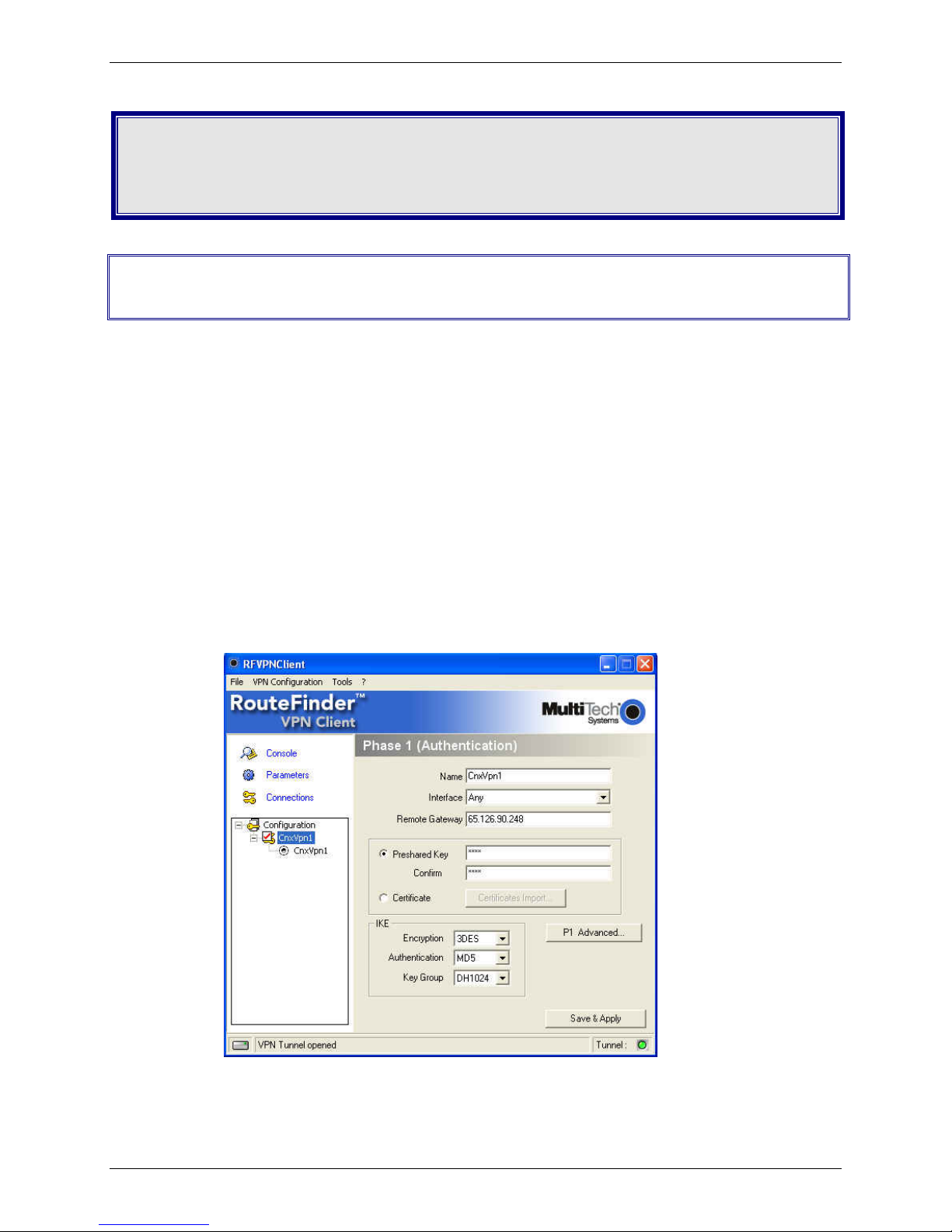
Prerequisite Step 1 – VPN Client Phase 1 Set Up
1. Open the IPSec VPN Client software.
2. Right click on RouteFinder Client VPN Configuration and select New Phase 1.
3. Enter a name for your connection in the Name field.
4. Choose Any for the client Interface if your IP address is dynamic or the IP address
provided by your ISP if Static (e.g., 65.126.90.250).
5. In the Remote Gateway field, enter the IP address of the VPN WAN for your Remote
Gateway (e.g., 65.126.90.248).
6. Enter the Shared Secret in Preshared Key for your network (the Secret has to match
on both ends). Then Confirm the shared secret by retyping the shared secret.
7. For IKE Authentication choose MD5.
Multi-Tech Systems, Inc. RF825 Series IPSec VPN Setup Examples – A Reference Guide (S000440B) 4
Page 5
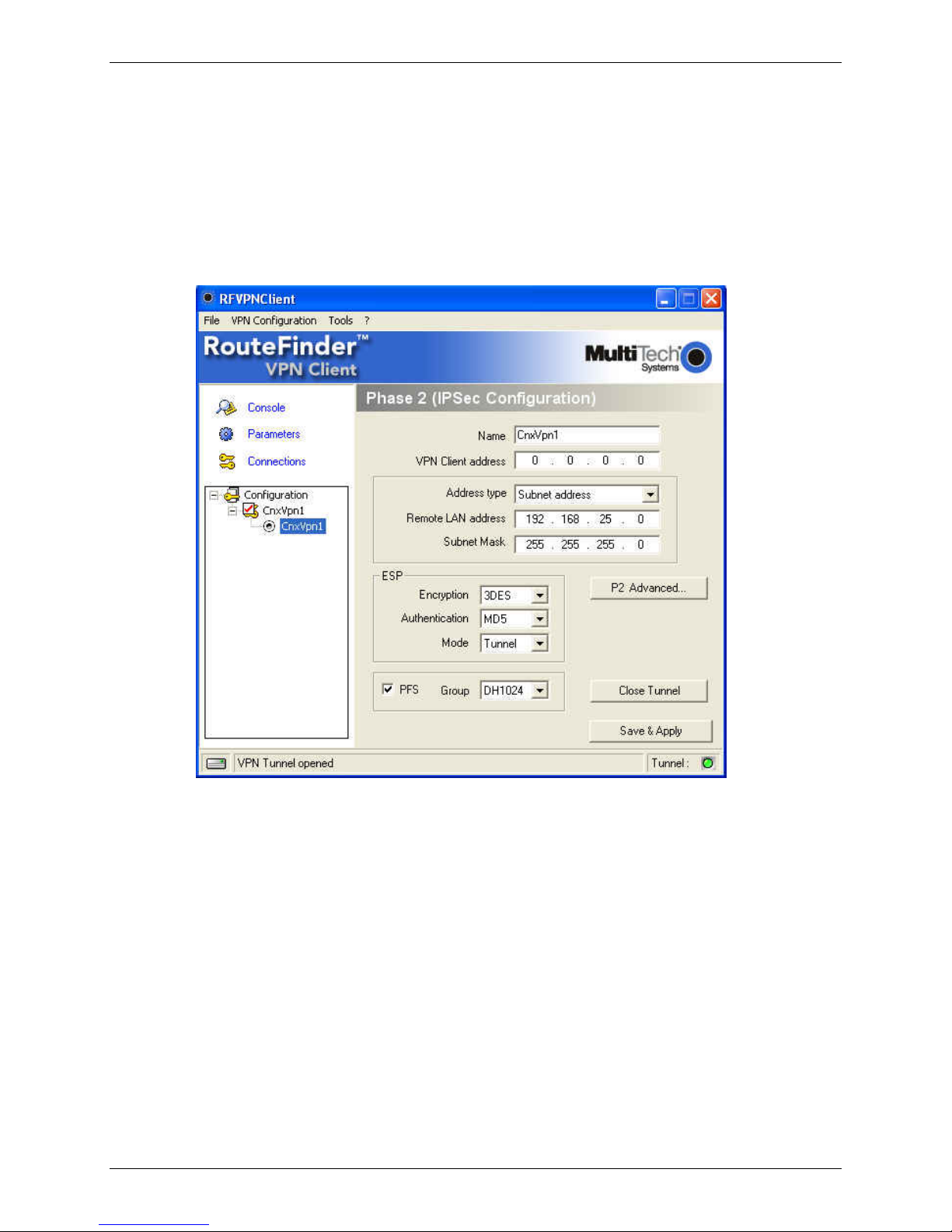
Prerequisite Step 2 – Phase 2 Setup
1. Start Phase 2 by right clicking on the name of your VPN Client you created in Phase 1.
2. The VPN Client address will be set to 0.0.0.0 unless you have a Static IP address (e.g.,
65.126.90.250).
3. The Address type is the type of setup on the host side. If it’s a network, then choose
Subnet address from the drop down list box and enter in the Remote LAN address
(e.g., 192.168.25.0) and the Subnet Mask (e.g., 255.255.255.0). If it’s a single IP
address, change it to that address.
4. For ESP Authentication choose MD5.
Chapter 1 – Non-NAT Setup Examples
Multi-Tech Systems, Inc. RF825 Series IPSec VPN Setup Examples – A Reference Guide (S000440B) 5
Page 6
Chapter 1 – Non-NAT Setup Examples
Example 1 – Set Up a RouteFinder and a VPN
Client Behind a Non-NAT Device
Note: Prerequisite Steps must be completed before you start this setup.
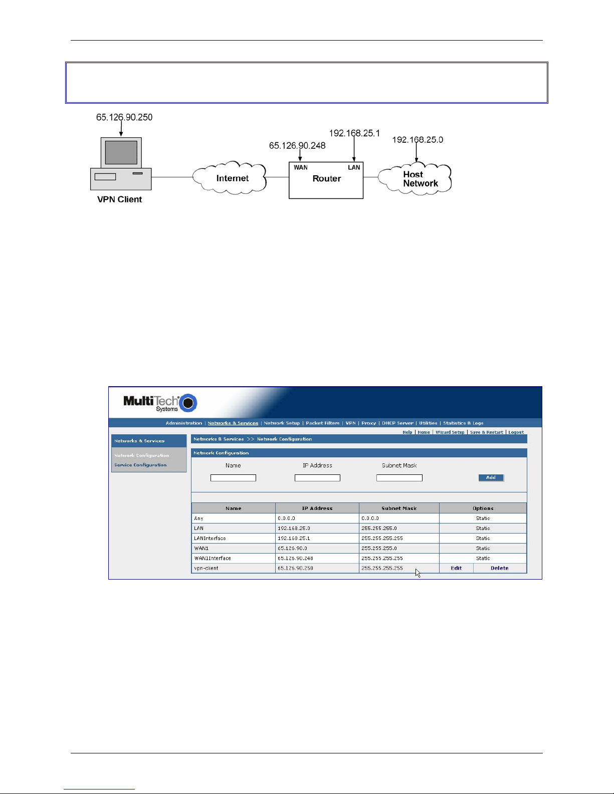
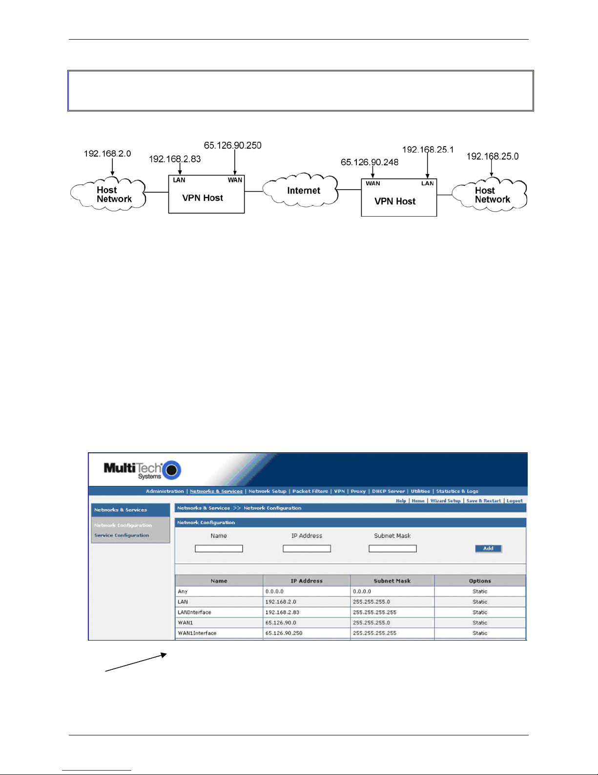
Step 1 – Network Setup
1. Log in to your RouteFinder and go to the Networks & Services screen.
2. Enter the Name of the network that you want to create for this connection.
Example: vpn-client.
3. Enter the IP Address of this new network. Example: 65.126.90.250
4. Enter the Subnet Mask for this network. The same address/mask pair should not be present
in the current list displayed on the screen.
5. Click the ADD button to add the new network
Multi-Tech Systems, Inc. RF825 Series IPSec VPN Setup Examples – A Reference Guide (S000440B) 6
Page 7
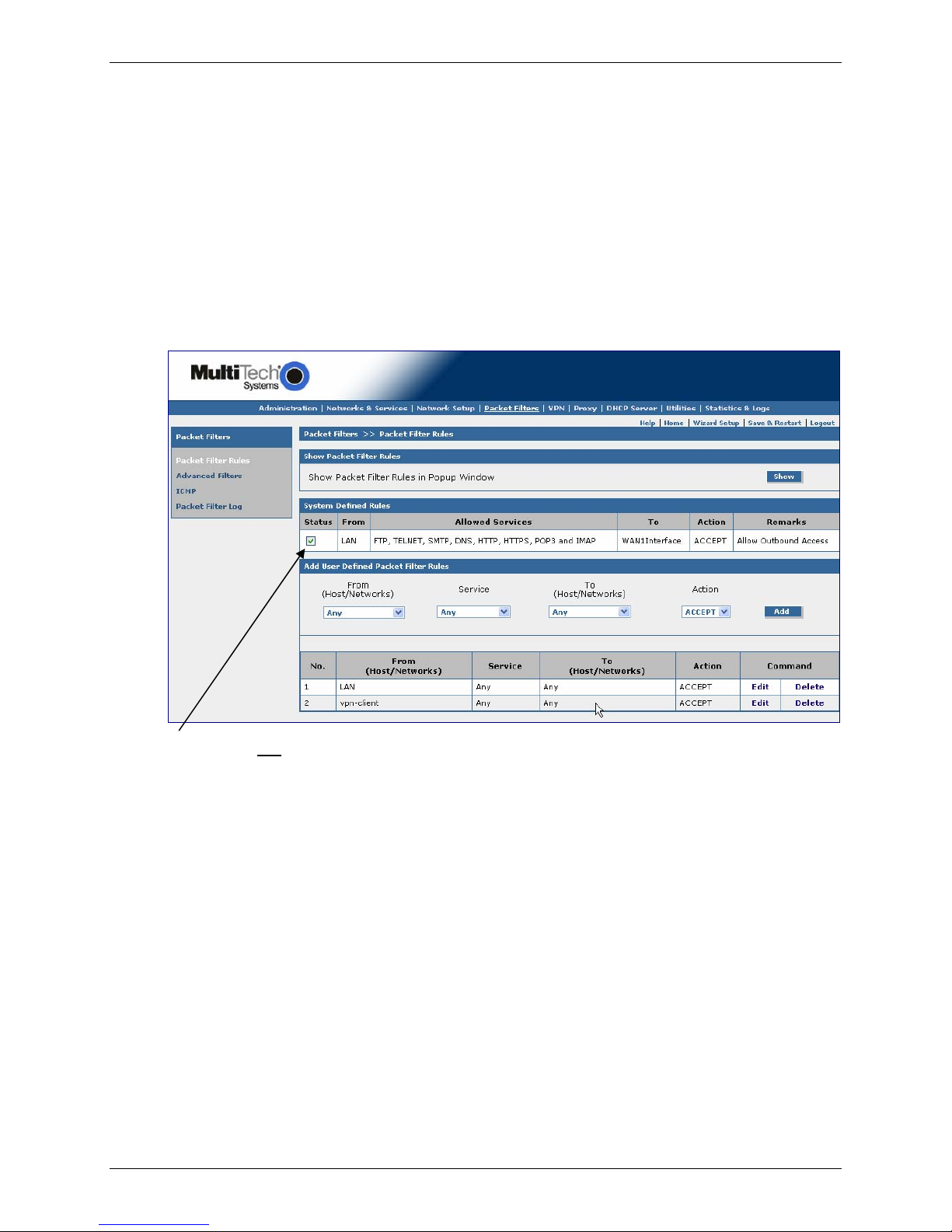
Step 2 – Packet Filters
1. Go to the Packet Filters screen to set the VPN client rights. These rights give the client
access across the tunnel to your host network.
2. Click on From (Host/Networks) and select the network you are allowing.
Example: vpn-client.
3. If you are not restricting the type of service, select Any for the To (Host/Network).
4. If the client is dynamic (unknown), set up an Any Any Any ACCEPT filter to allow any
network to come in.
5. Click the Add button to add this Packet Filter rule.
Chapter 1 – Non-NAT Setup Examples
Important Note: Do not check the Status box. When adding a user-defined rule, leave the Status
box unchecked.
Multi-Tech Systems, Inc. RF825 Series IPSec VPN Setup Examples – A Reference Guide (S000440B) 7
Page 8
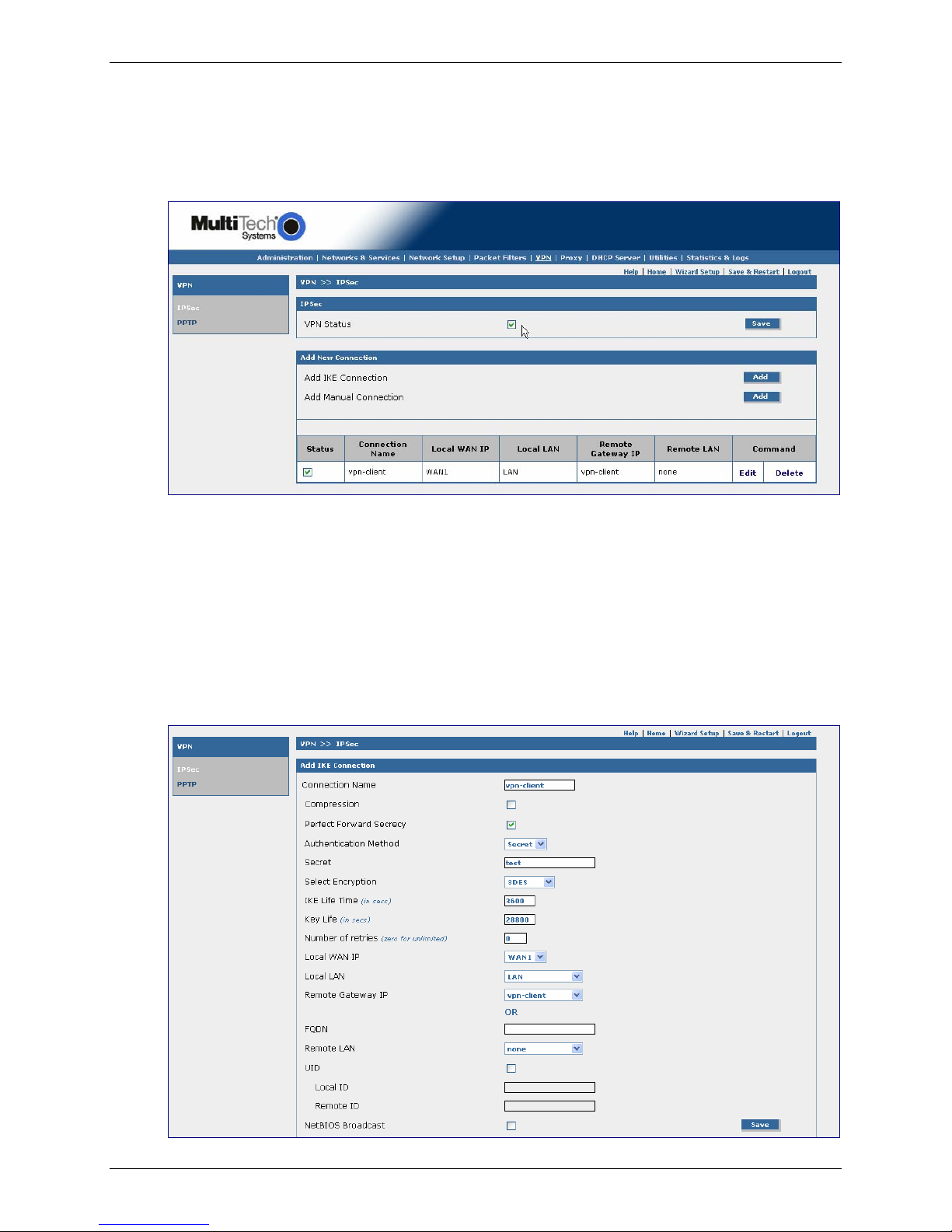
Step 3 – VPN Setup
1. Go to the VPN > IPSec screen.
2. Click the VPN Status check box to enable IPSec. Then click the Save button.
3. Select Add an IKE Connection by clicking the corresponding Add button.
Chapter 1 – Non-NAT Setup Examples
The Add an IKE Connection screen displays. All settings can be left at the default unless
otherwise indicated:
1. Connection Name: Enter in the name of the VPN tunnel you want to create. Example: vpn-
client.
2. Secret: Enter in the Secret (which has to match on both ends of the tunnel)
3. Local WAN IP: Select WAN1
4. Local LAN: Select LAN
5. Remote LAN: Select vpn-client. Note that you select Any if the remote client is Dynamic.
6. Click the Save button to save your tunnel.
Multi-Tech Systems, Inc. RF825 Series IPSec VPN Setup Examples – A Reference Guide (S000440B) 8
Page 9
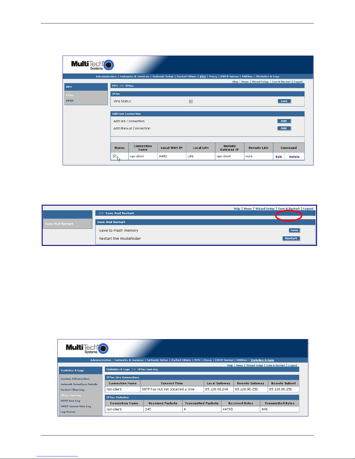
Chapter 1 – Non-NAT Setup Examples
Note:
Make sure to check the Status box at the bottom of the screen on the left side to activate the
newly created tunnel.
Step 4 – Save and Restart
Select the Save and Restart button located just under the menu bar. The Save and Restart
screen displays.
Save to Flash Memory
If a connection is established, then the settings have been entered correctly and your basic
configuration is now complete. Now, you must save your settings to the Flash Memory; this saves
the current settings in the flash prom and prevents settings from getting lost at the next power up.
Restart
This is optional. You do not have to restart the RouteFinder after saving to the flash memory.
Step 5 – Checking the Tunnel
To see if the tunnel is up you can click on Statistics & Logs and go to the IPSec Live Log. You
will see whether or not the connection is up. You will also see information about the data, if any,
that is being sent across the tunnel.
Multi-Tech Systems, Inc. RF825 Series IPSec VPN Setup Examples – A Reference Guide (S000440B) 9
Page 10
Chapter 1 – Non-NAT Setup Examples
Example 2 – A Setup Using Two RouteFinders
Behind a Non-NAT Device
Side A Side B
Note: Prerequisite Steps must be completed before you start this setup.
The Following Directions Apply to Side A of Example 2
Step 1 for Side A – Network Setup
1. Log in to your RouteFinder and go to the Networks & Services screen.
2. Enter a Name for the remote WAN IP address. Example: Remote-WAN
3. Enter the remote WAN IP Address (Ex. 65.126.90.250) with a single Subnet Mask of
255.255.255.255
4. Click Add to add the network to the list
5. Enter a Name for the remote LAN IP Address. Example: Remote-LAN
6. Enter the remote LAN IP Address (Ex. 192.168.2.0) with a network Subnet Mask for the
255.255.255.0.
Remote-WAN 65.126.90.248 255.255.255.255 Edit | Delete
Remote-LAN 192.168.25.0 255.255.255.0 Edit | Delete
Once the network configuration is complete, the information about that network displays at the bottom
of the screen.
Multi-Tech Systems, Inc. RF825 Series IPSec VPN Setup Examples – A Reference Guide (S000440B) 10
Page 11

Step 2 for Side A – Packet Filters
1. Go to the Packet Filters screen to setup another network across the VPN tunnel with the
rights to access across the tunnel
2. Click on From (Host/Networks) and select the network you are allowing. Example: ANY.
Note that you should already have the LAN Any Any Accept listed.
3. If you are not restricting the type of service, select Any for the To (Host/Network).
4. Click the Add button to add the Packet Filter rule.
Important Note: Do not
Status box unchecked.
check the Status box. When adding a user-defined rule, leave the
Chapter 1 – Non-NAT Setup Examples
Step 3 for Side A –VPN Setup
1. Go to the VPN > IPSec screen.
2. Click the VPN Status check box to enable IPSec. Then click the Save button.
3. Select Add an IKE Connection by clicking the corresponding Add button.
Multi-Tech Systems, Inc. RF825 Series IPSec VPN Setup Examples – A Reference Guide (S000440B) 11
Page 12

Chapter 1 – Non-NAT Setup Examples
The Add an IKE Connection screen displays. All settings can be left at the default unless
otherwise indicated:
1. Connection Name: Enter in the name of the VPN tunnel you want to create. Example:
test-tunnel
2. Secret: Enter in the Secret (which has to match on both ends of the tunnel)
3. Local WAN IP: Select WAN1
4. Local LAN: Select LAN
5. Remote LAN: Select Remote-LAN. Note that you should select ANY if the network is
unknown or the name you created is for the static IP)
6. Click the Save button to save your tunnel.
Note:
Make sure to check the Status box at the bottom of the screen on the left side to activate the
newly created tunnel.
Multi-Tech Systems, Inc. RF825 Series IPSec VPN Setup Examples – A Reference Guide (S000440B) 12
Page 13

Chapter 1 – Non-NAT Setup Examples
Step 4 for Side A – Save and Restart
Select the Save and Restart button located just under the menu bar. The Save and Restart
screen displays.
Save to Flash Memory
If a connection is established, then the settings have been entered correctly and your basic
configuration is now complete. Now, you must save your settings to the Flash Memory; this saves
the current settings in the flash prom and prevents settings from getting lost at the next power up.
Restart
This is optional. You do not have to restart the RouteFinder after saving to the flash memory.
Step 5 for Side A – Checking the Tunnel
To see if the tunnel is up you can click on Statistics & logs and go to the IPSec Live Log. You will
see the connection up; and if any data is being sent across, you will see that information here.
Multi-Tech Systems, Inc. RF825 Series IPSec VPN Setup Examples – A Reference Guide (S000440B) 13
Page 14

Chapter 1 – Non-NAT Setup Examples
The Following Directions Apply to the RF830 (Side B)
Step 1 for Side B – Network Setup
1. Log in to your RouteFinder and go to Networks & Services screen.
2. Enter a Name for the remote WAN IP address. Example: remote-WAN
3. Enter the remote WAN IP Address (Ex. 65.126.90.248) with a single Subnet Mask of
255.255.255.255.
4. Click Add to add the network to the list.
5. Enter a Name for the remote LAN IP address. Example: Remote-LAN
6. Enter the remote LAN IP Address (Ex. 192.168.25.0) with a network Subnet Mask of
255.255.255.0.
Multi-Tech Systems, Inc. RF825 Series IPSec VPN Setup Examples – A Reference Guide (S000440B) 14
Page 15

Step 2 for Side B – Packet Filters
1. Go to the Packet Filters screen to setup the other network across the VPN tunnel with the
rights to access across the tunnel
2. Click on From (Host/Networks) and select the network you are allowing (you should already
have the LAN Any Any Accept listed).
3. If you are not restricting the type of service, select Any for the To (Host/Network).
4. Click the Add button to save the Packet Filter rule.
Important Note: Do not
Status box unchecked.
check the Status box. When adding a user-defined rule, leave the
Chapter 1 – Non-NAT Setup Examples
Step 3 for Side B – VPN Setup
1. Go to the VPN > IPSec screen.
2. Click the VPN Status check box to enable IPSec. Then click the Save button.
3. Select Add an IKE Connection by clicking the corresponding Add button.
Multi-Tech Systems, Inc. RF825 Series IPSec VPN Setup Examples – A Reference Guide (S000440B) 15
Page 16

Chapter 1 – Non-NAT Setup Examples
The Add an IKE Connection screen displays. All settings can be left at the default unless
otherwise indicated:
1. Connection Name: Enter in the name of the VPN tunnel you want to create. Example:
test-tunnel.
2. Secret: Enter in the Secret (which has to match on both ends of the tunnel)
3. Local WAN IP: Select WAN1
4. Local LAN: Select LAN
5. Remote LAN: Select Remote-LAN (Select Any if unknown or the name you created
has a static IP)
6. Click the Save button to save your tunnel.
Note:
Make sure to check the Status box at the bottom of the screen on the left side to activate the
newly created tunnel.
Multi-Tech Systems, Inc. RF825 Series IPSec VPN Setup Examples – A Reference Guide (S000440B) 16
Page 17

Chapter 1 – Non-NAT Setup Examples
Step 4 for Side B – Save and Restart
Select the Save and Restart button located just under the menu bar. The Save and Restart
screen displays.
Save to Flash Memory
If a connection is established, then the settings have been entered correctly and your basic
configuration is now complete. Now, you must save your settings to the Flash Memory; this saves
the current settings in the flash prom and prevents settings from getting lost at the next power up.
Restart
This is optional. You do not have to restart the RouteFinder after saving to the flash memory.
Step 5 for Side B – Checking the Tunnel
To see if the tunnel is up you can click on Statistics & Logs and go to the IPSec Live Log. You will
see whether or not the connection is up. You will also see the information, if any, about the data being
sent across the tunnel.
Multi-Tech Systems, Inc. RF825 Series IPSec VPN Setup Examples – A Reference Guide (S000440B) 17
Page 18

Chapter 2 – Behind NAT Setup Examples
Chapter 2 – NAT Setup Examples
Prerequisite Steps – Set Up VPN Client Using
IPSec VPN Client Software
The NAT setup requires the VPN client to be set up first in the IPSec VPN Client software, and then the
VPN tunnel for the RouteFinder can be set up using the RouteFinder software.
Prerequisite Step 1 – VPN Client Phase 1 Setup
(Behind NAT)
1. Open the IPSec VPN Client software.
2. Right click on RouteFinder Client VPN Configuration and select New Phase 1.
3. Enter the name of your connection in the Name field.
4. Choose Any for the client Interface if your IP address is dynamic or the IP address provided
by your ISP is Static. Example: 65.126.90.250.
5. Enter the IP address of the VPN WAN for your Remote Gateway. Example: 65.126.90.248.
6. Enter the Shared Secret in Preshared Key for your network (the secret has to match on both
ends). Then Confirm the shared secret by entering the Shared Secret again.
7. For IKE Authentication choose MD5.
8. Click the P1 Advanced button.
Multi-Tech Systems, Inc. RF825 Series IPSec VPN Setup Examples – A Reference Guide (S000440B) 18
Page 19

Chapter 2 – Behind NAT Setup Examples
Prerequisite Step 2 – Client Phase 1 Advanced
Setup (Behind NAT)
This screen displays after clicking the P1 Advanced button on the previous screen.
1. Select the IP Address from the drop down list box for the Local ID.
2. Then enter the IP address of the VPN Client in the text box labeled Set the value for the ID
field. Example: 192.168.2.8
3. Select IP Address for the Remote ID.
4. Then enter the IP address of the RouteFinder in the Set the value for the ID field. Example:
65.126.90.248
5. Click OK.
Multi-Tech Systems, Inc. RF825 Series IPSec VPN Setup Examples – A Reference Guide (S000440B) 19
Page 20

Chapter 2 – Behind NAT Setup Examples
Prerequisite Step 3 – Client Phase 2 Setup (Behind
NAT)
1. Start Phase 2 by right clicking on the name of your VPN Client you created in Phase 1.
2. The VPN Client address will be set to 0.0.0.0 unless you have a Static IP address. Example:
65.126.90.250
3. The Address type is the type of setup on the host side. If it’s a network, then choose
Subnet address and enter the Remote LAN address (Ex. 192.168.25.0) and the Subnet
Mask (Ex. 255.255.255.0). If it’s a single IP address, change it to that address.
4. For ESP Authentication choose MD5.
5. Click OK.
Multi-Tech Systems, Inc. RF825 Series IPSec VPN Setup Examples – A Reference Guide (S000440B) 20
Page 21

Chapter 2 – Behind NAT Setup Examples
Example 1 – Set Up a RouteFinder with a
Tunnel to a Client Behind a NAT Device
Note: Prerequisite Steps must be completed before you start this setup.
Step 1 – Network Setup
1. Log into your RouteFinder and go to the Networks & Services screen.
2. Create and enter in the Name, IP Address, and Subnet Mask of the Remote WAN.
3. Click the Add button to add the new network to the list
4. Create and enter in the Name, IP Address, and Subnet Mask of the Remote VPN Client.
5. Click the Add to add the new network to the list
Multi-Tech Systems, Inc. RF825 Series IPSec VPN Setup Examples – A Reference Guide (S000440B) 21
Page 22

Step 2 – Packet Filters
1. Go to the Packet Filters screen to give the client at the other end of the VPN tunnel the
rights to access across the tunnel.
2. Click on From (Host/Networks) and select the remote client and remote WAN IP you are
allowing to access your network (you should already have the LAN Any Any Accept listed).
3. If you are not restricting what type of service, select Any for the To (Host/Network).
4. Click the Add button to add the Packet Filter rule.
Chapter 2 – Behind NAT Setup Examples
Important Note: Do not
check the Status box. When adding a user-defined rule, leave the
Status box unchecked.
Step 3 – VPN Setup
1. Go to the VPN > IPSec screen.
2. Click on the VPN Status check box to enable IPSec. Then click the Save button.
3. Select Add an IKE Connection by clicking the corresponding Add button.
Multi-Tech Systems, Inc. RF825 Series IPSec VPN Setup Examples – A Reference Guide (S000440B) 22
Page 23

Chapter 2 – Behind NAT Setup Examples
The Add an IKE Connection screen displays. All settings can be left at the default unless
otherwise indicated:
1. Connection Name: Enter in the name of the VPN tunnel you want to create
2. Secret: Enter in the Secret (which has to match on both ends of the tunnel)
3. Local WAN IP: Select WAN1
4. Local LAN: Select LAN
5. Remote LAN: Select VPN-client
6. UID: Click the UID box to enable UID.
7. Local ID: Enter the WAN IP Address of the RouteFinder.
8. Remote ID: Enter the WAN IP Address of the remote device that is acting as the VPN
tunnel. This can be the address number or the name you have given it.
9. Click the Save button to save your tunnel settings.
Note:
Make sure to check the Status box at the bottom of the screen on the left side to activate the
newly created tunnel.
Multi-Tech Systems, Inc. RF825 Series IPSec VPN Setup Examples – A Reference Guide (S000440B) 23
Page 24

Chapter 2 – Behind NAT Setup Examples
Step 4 – Save and Restart
Select the Save and Restart button located just under the menu bar. The Save and Restart
screen displays.
Save to Flash Memory
If a connection is established, then the settings have been entered correctly and your basic
configuration is now complete. Now, you must save your settings to the Flash Memory; this saves
the current settings in the flash prom and prevents settings from getting lost at the next power up.
Restart
This is optional. You do not have to restart the RouteFinder after saving to the flash memory.
Step 5 – Checking the Tunnel
To see if the tunnel is up you can click on Statistics & logs and go to the IPSec Live Log. You will
see the connection up; and if any data is being sent across, you will see that information here.
Multi-Tech Systems, Inc. RF825 Series IPSec VPN Setup Examples – A Reference Guide (S000440B) 24
Page 25

Chapter 2 – Behind NAT Setup Examples
Example 2 – Set Up Two RouteFinders Behind
a NAT Device
Side A Side B
Note: Prerequisite Steps must be completed before you start this setup.
Step 1 -- Network Setup
1. Log into your RouteFinder and go to the Networks & Services screen.
2. Create and enter in the Name, IP Address, and Subnet Mask of the Remote WAN.
3. Click the Add button to add the new network to the list
4. Create and enter in the Name, IP Address, and Subnet Mask of the Remote LAN.
5. Click the Add to add the new network to the list
Remote-WAN 65.126.90.248 255.255.255.255 Edit | Delete
Remote-LAN 192.168.25.0 255.255.255.0 Edit | Delete
Once the network configuration is complete, the information about that network displays at the bottom of
the screen.
Multi-Tech Systems, Inc. RF825 Series IPSec VPN Setup Examples – A Reference Guide (S000440B) 25
Page 26

Step 2 – Packet Filters
1. Go to the Packet Filters screen to give the client at the other end of the VPN tunnel the
rights to access across the tunnel.
2. Click on From (Host/Networks) and select the remote client and remote WAN IP you are
allowing to access your network (you should already have the LAN Any Any Accept listed).
3. If you are not restricting the type of service, select Any for the To (Host/Network).
4. Click the Add button to add this Packet Filter rule.
Important Note: Do not
Status box unchecked.
check the Status box. When adding a user-defined rule, leave the
Chapter 2 – Behind NAT Setup Examples
Multi-Tech Systems, Inc. RF825 Series IPSec VPN Setup Examples – A Reference Guide (S000440B) 26
Page 27

Step 3 -- VPN Setup
1. Go to the VPN > IPSec screen.
2. Click on the VPN Status check box to enable IPSec. Then click the Save button.
3. Select Add an IKE Connection by clicking the corresponding Add button.
Chapter 2 – Behind NAT Setup Examples
The Add an IKE Connection screen displays. All settings can be left at the default unless
otherwise indicated:
1. Connection Name: Enter in the name of the VPN tunnel you want to create
2. Secret: Enter in the Secret (which has to match on both ends of the tunnel)
3. Local WAN IP: Select WAN1
4. Local LAN: Select LAN
5. Remote LAN: Select RF820VPN-LAN. (Any if unknown or the name you created for the
static IP)
6. UID: Click the UID checkbox to enable UID.
7. Local ID: Enter the IP Address of the RouteFinder’s WAN IP.
8. Remote ID: Enter IP Address of the remote device that is at the other end of the VPN
tunnel.
9. Click the Save button to save your tunnel.
Multi-Tech Systems, Inc. RF825 Series IPSec VPN Setup Examples – A Reference Guide (S000440B) 27
Page 28

Chapter 2 – Behind NAT Setup Examples
Example 3 – Set Up the RouteFinder Going to
a VPN behind a NAT Device
Step 1 -- Network Setup
1. Log into your RouteFinder and go to the Networks & Services screen.
2. Create and enter in the Name, IP Address, and Subnet Mask of the Remote WAN.
3. Click the Add button to add the new network to the list.
4. Create and enter in the Name, IP Address, and Subnet Mask of the Remote LAN
5. Click Add to add the new network to the list
Multi-Tech Systems, Inc. RF825 Series IPSec VPN Setup Examples – A Reference Guide (S000440B) 28
Page 29

Step 2 – Packet Filters
1. Go to the Packet Filters screen to give the client at the other end of the VPN tunnel the
rights to access across the tunnel.
2. Click on From (Host/Networks) and select the remote WAN IP and remote LAN IP you are
allowing to access your network (you should already have the LAN Any Any Accept listed).
3. If you are not restricting the type of service, select Any for the To (Host/Network).
4. Click the Add button to add this Packet Filter rule.
Chapter 2 – Behind NAT Setup Examples
Important Note: Do not
check the Status box. When adding a user-defined rule, leave the
Status box unchecked.
Step 3 -- VPN Setup
1. Go to the VPN > IPSec screen.
2. Click on the VPN Status check box to enable IPSec. Then click the Save button.
3. Select Add an IKE Connection by clicking the corresponding Add button.
Multi-Tech Systems, Inc. RF825 Series IPSec VPN Setup Examples – A Reference Guide (S000440B) 29
Page 30

Chapter 2 – Behind NAT Setup Examples
The Add an IKE Connection screen displays. All settings can be left at the default unless
otherwise indicated:
1. Connection Name: Enter in the name of the VPN tunnel you want to create
2. Secret: Enter in the Secret (which has to match on both ends of the tunnel)
3. Local WAN IP: Select WAN1
4. Local LAN: Select LAN
5. Remote LAN: Select remote-WAN.
6. UID: Click the UID checkbox to enable UID.
7. Local ID: Enter the IP Address of the RouteFinder’s WAN IP.
8. Remote ID: Enter IP Address of the remote device that is at the other end of the VPN
tunnel.
9. Click the Save button to save your tunnel.
Note:
Make sure to check the Status box at the bottom of the screen on the left side to activate the
newly created tunnel.
Multi-Tech Systems, Inc. RF825 Series IPSec VPN Setup Examples – A Reference Guide (S000440B) 30
Page 31

Chapter 2 – Behind NAT Setup Examples
Step 4 – Save and Restart
Select the Save and Restart button located just under the menu bar. The Save and Restart
screen displays.
Save to Flash Memory
If a connection is established, then the settings have been entered correctly and your basic
configuration is now complete. Now, you must save your settings to the Flash Memory; this saves
the current settings in the flash prom and prevents settings from getting lost at the next power up.
Restart
This is optional. You do not have to restart the RouteFinder after saving to the flash memory.
Step 5 – Checking the Tunnel
You can check the status of your VPN tunnel by clicking on Statistics & Logs and going to the IPSec
Live Log. You will see the connection up (if connected), and you will see the statistics related to the
data being sent across the tunnel.
Multi-Tech Systems, Inc. RF825 Series IPSec VPN Setup Examples – A Reference Guide (S000440B) 31
Page 32

Chapter 3 – A Reference Table of Commonly Supported Subnets
Chapter 3 – A Reference Table of
Commonly Supported Subnets
This table lists commonly supported Subnets organized by Address.
255.255.255.128 N.N.N.0 N.N.N.1-126 N.N.N.127
/25 N.N.N.128 N.N.N.129-254 N.N.N.255
255.255.255.192 N.N.N.0 N.N.N.1-62 N.N.N.63
/26 N.N.N.64 N.N.N.65-126 N.N.N.127
N.N.N.128 N.N.N.129-190 N.N.N.191
N.N.N.192 N.N.N.193-254 N.N.N.255
255.255.255.224 N.N.N.0 N.N.N.1-30 N.N.N.31
/27 N.N.N.32 N.N.N.33-62 N.N.N.63
N.N.N.64 N.N.N.65-94 N.N.N.95
N.N.N.96 N.N.N.97-126 N.N.N.127
N.N.N.128 N.N.N.129-158 N.N.N.159
N.N.N.160 N.N.N.161-190 N.N.N.191
N.N.N.192 N.N.N.193-222 N.N.N.223
N.N.N.224 N.N.N.225-254 N.N.N.255
255.255.255.240 N.N.N.0 N.N.N.1-14 N.N.N.15
/28 N.N.N.16 N.N.N.17-30 N.N.N.31
N.N.N.32 N.N.N.33-46 N.N.N.47
N.N.N.48 N.N.N.49-62 N.N.N.63
N.N.N.64 N.N.N.65-78 N.N.N.79
N.N.N.80 N.N.N.81-94 N.N.N.95
N.N.N.96 N.N.N.97-110 N.N.N.111
N.N.N.112 N.N.N.113-126 N.N.N.127
N.N.N.128 N.N.N.129-142 N.N.N.143
N.N.N.144 N.N.N.145-158 N.N.N.159
N.N.N.160 N.N.N.161-174 N.N.N.175
N.N.N.176 N.N.N.177-190 N.N.N.191
N.N.N.192 N.N.N.193-206 N.N.N.207
N.N.N.208 N.N.N.209-222 N.N.N.223
N.N.N.224 N.N.N.225-238 N.N.N.239
N.N.N.240 N.N.N.241-254 N.N.N.255
255.255.255.248 N.N.N.0 N.N.N.1-6 N.N.N.7
/29 N.N.N.8 N.N.N.9-14 N.N.N.15
N.N.N.16 N.N.N.17-22 N.N.N.23
N.N.N.24 N.N.N.25-30 N.N.N.31
N.N.N.32 N.N.N.33-38 N.N.N.39
N.N.N.40 N.N.N.41-46 N.N.N.47
N.N.N.48 N.N.N.49-54 N.N.N.55
N.N.N.56 N.N.N.57-62 N.N.N.63
N.N.N.64 N.N.N.65-70 N.N.N.71
N.N.N.72 N.N.N.73-78 N.N.N.79
N.N.N.80 N.N.N.81-86 N.N.N.87
N.N.N.88 N.N.N.89-94 N.N.N.95
N.N.N.96 N.N.N.97-102 N.N.N.103
N.N.N.104 N.N.N.105-110 N.N.N.111
N.N.N.112 N.N.N.113-118 N.N.N.119
N.N.N.120 N.N.N.121-126 N.N.N.127
N.N.N.128 N.N.N.129-134 N.N.N.135
N.N.N.136 N.N.N.137-142 N.N.N.143
N.N.N.144 N.N.N.145-150 N.N.N.151
N.N.N.152 N.N.N.153-158 N.N.N.159
N.N.N.160 N.N.N.161-166 N.N.N.167
N.N.N.168 N.N.N.169-174 N.N.N.175
N.N.N.176 N.N.N.177-182 N.N.N.183
N.N.N.184 N.N.N.185-190 N.N.N.191
Network Number Hosts Available Broadcast Address
Network Number Hosts Available Broadcast Address
Network Number Hosts Available Broadcast Address
Network Number Hosts Available Broadcast Address
Network Number Hosts Available Broadcast Address
Multi-Tech Systems, Inc. RF825 Series IPSec VPN Setup Examples – A Reference Guide (S000440B) 32
Page 33

Chapter 3 – A Reference Table of Commonly Supported Subnets
N.N.N.192 N.N.N.193-198 N.N.N.199
N.N.N.200 N.N.N.201-206 N.N.N.207
N.N.N.208 N.N.N.209-214 N.N.N.215
N.N.N.216 N.N.N.217-222 N.N.N.223
N.N.N.224 N.N.N.225-230 N.N.N.231
N.N.N.232 N.N.N.233-238 N.N.N.239
N.N.N.240 N.N.N.241-246 N.N.N.247
N.N.N.248 N.N.N.249-254 N.N.N.255
255.255.255.252 N.N.N.0 N.N.N.1-2 N.N.N.3
/30 N.N.N.4 N.N.N.5-6 N.N.N.7
N.N.N.8 N.N.N.9-10 N.N.N.11
N.N.N.12 N.N.N.13-14 N.N.N.15
N.N.N.16 N.N.N.17-18 N.N.N.19
N.N.N.20 N.N.N.21-22 N.N.N.23
N.N.N.24 N.N.N.25-26 N.N.N.27
N.N.N.28 N.N.N.29-30 N.N.N.31
N.N.N.32 N.N.N.33-34 N.N.N.35
N.N.N.36 N.N.N.37-38 N.N.N.39
N.N.N.40 N.N.N.41-42 N.N.N.43
N.N.N.44 N.N.N.45-46 N.N.N.47
N.N.N.48 N.N.N.49-50 N.N.N.51
N.N.N.52 N.N.N.53-54 N.N.N.55
N.N.N.56 N.N.N.57-58 N.N.N.59
N.N.N.60 N.N.N.61-62 N.N.N.63
N.N.N.64 N.N.N.65-66 N.N.N.67
N.N.N.68 N.N.N.69-70 N.N.N.71
N.N.N.72 N.N.N.73-74 N.N.N.75
N.N.N.76 N.N.N.77-78 N.N.N.79
N.N.N.80 N.N.N.81-82 N.N.N.83
N.N.N.84 N.N.N.85-86 N.N.N.87
N.N.N.88 N.N.N.89-90 N.N.N.91
N.N.N.92 N.N.N.93-94 N.N.N.95
N.N.N.96 N.N.N.97-98 N.N.N.99
N.N.N.100 N.N.N.101-102 N.N.N.103
N.N.N.104 N.N.N.105-106 N.N.N.107
N.N.N.108 N.N.N.109-110 N.N.N.111
N.N.N.112 N.N.N.113-114 N.N.N.115
N.N.N.116 N.N.N.117-118 N.N.N.119
N.N.N.120 N.N.N.121-122 N.N.N.123
N.N.N.124 N.N.N.125-126 N.N.N.127
N.N.N.128 N.N.N.129-130 N.N.N.131
N.N.N.132 N.N.N.133-134 N.N.N.135
N.N.N.136 N.N.N.137-138 N.N.N.139
N.N.N.140 N.N.N.141-142 N.N.N.143
N.N.N.144 N.N.N.145-146 N.N.N.147
N.N.N.148 N.N.N.149-150 N.N.N.151
N.N.N.152 N.N.N.153-154 N.N.N.155
N.N.N.156 N.N.N.157-158 N.N.N.159
N.N.N.160 N.N.N.161-162 N.N.N.163
N.N.N.164 N.N.N.165-166 N.N.N.167
N.N.N.168 N.N.N.169-170 N.N.N.171
N.N.N.172 N.N.N.173-174 N.N.N.175
N.N.N.176 N.N.N.177-178 N.N.N.179
N.N.N.180 N.N.N.181-182 N.N.N.183
N.N.N.184 N.N.N.185-186 N.N.N.187
N.N.N.188 N.N.N.189-190 N.N.N.191
N.N.N.192 N.N.N.193-194 N.N.N.195
N.N.N.196 N.N.N.197-198 N.N.N.199
N.N.N.200 N.N.N.201-202 N.N.N.203
N.N.N.204 N.N.N.205-206 N.N.N.207
N.N.N.208 N.N.N.209-210 N.N.N.211
N.N.N.212 N.N.N.213-214 N.N.N.215
N.N.N.216 N.N.N.217-218 N.N.N.219
N.N.N.220 N.N.N.221-222 N.N.N.223
N.N.N.224 N.N.N.225-226 N.N.N.227
N.N.N.228 N.N.N.229-230 N.N.N.231
N.N.N.232 N.N.N.233-234 N.N.N.235
N.N.N.236 N.N.N.237-238 N.N.N.239
N.N.N.240 N.N.N.241-242 N.N.N.243
N.N.N.244 N.N.N.245-246 N.N.N.247
N.N.N.248 N.N.N.249-250 N.N.N.251
N.N.N.252 N.N.N.253-254 N.N.N.255
Network Number Hosts Available Broadcast Address
Multi-Tech Systems, Inc. RF825 Series IPSec VPN Setup Examples – A Reference Guide (S000440B) 33
 Loading...