

Page 1

Model RF102S
Dual Serial Port Router
with built-in 4-port 10/100 Switch
User Guide
Page 2

User Guide
Model RF102S Serial Port Router
with Built-in 4-port 10/100 Switch
P/N S0000139 Revision A
This publication may not be reproduced, in whole or in part, without prior expressed written permission
from Multi-Tech Systems, Inc. All rights reserved.
Copyright © 2001 by Multi Tech Systems, Inc.
Multi-Tech Systems, Inc. makes no representations or warranties with respect to the content hereof and
specifically disclaims any implied warranties of merchantability or fitness for any particular purpose.
Furthermore, Multi-Tech Systems, Inc. reserves the right to revise this publication and to make changes
from time to time in the content hereof without obligation of Multi-Tech Systems, Inc. to notify any person
or organization of such revisions or changes.
Record of Revisions
Revision Description
A
(02/28/01) Manual released.
PATENTS
This device is covered by one or more of the following patents: 6,031,867; 6,012,113; 6,009,082;
5,905,794; 5,864,560; 5,815,567; 5,815,503; 5,812,534; 5,809,068; 5,790,532; 5,764,628; 5,764,627;
5,754,589; D394,250; 5,724,356; 5,673,268; 5,673,257; 5,644,594; 5,628,030; 5,619,508; 5,617,423;
5,600,649; 5,592,586; 5,577,041; 5,574,725; D374,222; 5,559,793; 5,546,448; 5,546,395; 5,535,204;
5,500,859; 5,471,470; 5,463,616; 5,453,986; 5,452,289; 5,450,425; D361,764; D355,658; D355,653;
D353,598; D353,144; 5,355,365; 5,309,562; 5,301,274. Other Patents Pending
TRADEMARKS
Trademark of Multi-Tech Systems, is the Multi-Tech logo. Windows, Windows 95, 98, NT and 2000 are
trademarks of Microsoft. All other trademarks are owned by their respective companies.
Multi-Tech Systems, Inc.
2205 Woodale Drive
Mounds View, Minnesota 55112 U.S.A.
(763) 785-3500 or (800) 328-9717
U. S. FAX (763) 785-9874
Technical Support (800) 972-2439
Internet Address: http://www.multitech.com
Page 3

Contents
Chapter 1 - Introduction.................................................................................6
Introduction ................................................................................................................................................ 7
Front Panel................................................................................................................................................. 8
Front Panel Description ....................................................................................................................... 8
Back Panel ................................................................................................................................................. 8
Back Panel Description........................................................................................................................ 8
Typical Applications.................................................................................................................................... 9
Connecting to a Network via Serial Device.......................................................................................... 9
Connecting a Remote User to the Internet ........................................................................................10
Specifications ............................................................................................................................................11
Chapter 2 - Hardware Installation................................................................12
Hardware Installation................................................................................................................................ 13
Safety................................................................................................................................................. 13
Unpacking the RF102S...................................................................................................................... 13
Cabling............................................................................................................................................... 14
Chapter 3 - Software Installation
and Configuration........................................................................................15
Software Installation and Configuration.................................................................................................... 16
Software Installation .......................................................................................................................... 16
Using RouteFinder Setup Wizard............................................................................................................. 17
Testing your Connection .................................................................................................................... 23
Chapter 4 - Telnet .........................................................................................24
Using Telnet to Configure your RouteFinder ............................................................................................ 25
Router IP Address.............................................................................................................................. 26
Router Subnet Mask .......................................................................................................................... 26
Router Name ..................................................................................................................................... 26
Router Password ............................................................................................................................... 26
Router MAC address ......................................................................................................................... 26
Async Port 1 and 2 Settings .............................................................................................................. 26
Chapter 5 - RouteFinder Manager ............................................................... 30
RouteFinder Manager .............................................................................................................................. 31
General Settings ...................................................................................................................................... 32
Remote Access - Remote Access Settings........................................................................................ 37
Enable IP Mapping - Virtual Server.................................................................................................... 38
Port Settings............................................................................................................................................. 39
Edit Login Script for Remote Access ................................................................................................. 40
Writing a login script for IP Routing.................................................................................................... 40
Modem String Settings ...................................................................................................................... 42
LAN DHCP Server ................................................................................................................................... 44
Routing Settings ....................................................................................................................................... 45
Routing T able..................................................................................................................................... 46
......................................................................................................................................... Filter Settings
47
Refresh Device List .................................................................................................................................. 51
Device Name and Password.................................................................................................................... 51
iii
Page 4

Save Settings to File ................................................................................................................................ 52
Load Settings ........................................................................................................................................... 53
Upgrade Firmware ................................................................................................................................... 53
General Diagnostic................................................................................................................................... 54
Chapter 6 - RouteFinder Monitor................................................................. 55
RouteFinder Monitor................................................................................................................................. 56
Running RouteFinder Monitor............................................................................................................ 56
Test Connection ....................................................................................................................................... 56
T erminate Connection .............................................................................................................................. 57
Save to File .............................................................................................................................................. 57
Save Now .......................................................................................................................................... 57
Autosave............................................................................................................................................ 58
IP Address/Name ..................................................................................................................................... 58
Event Messages....................................................................................................................................... 59
TCP/IP Tab............................................................................................................................................... 59
Time Tab................................................................................................................................................... 60
Status Tab ................................................................................................................................................ 61
Statistics Tab ............................................................................................................................................ 62
Chapter 7 - LAN Client Settings ..................................................................63
LAN Client Settings .................................................................................................................................. 64
Setting up Remote Access Clients........................................................................................................... 64
Accessing a Windows NT Server ...................................................................................................... 64
Accessing a Novell Server................................................................................................................. 71
Accessing a Windows NT Server and a Novell NetWare Server....................................................... 76
Accessing a Unix Server.................................................................................................................... 84
Make New Connection (Windows 2000 only) .................................................................................... 88
Chapter 8 - LAN-to-LAN Settings ................................................................89
LAN -to- LAN Settings.............................................................................................................................. 90
Setting up LAN -to- LAN Routing ................................................................................................ ....... 90
Using the Find Computer command ......................................................................................................
91
Using LMHosts .................................................................................................................................. 91
Chapter 9 - Troubleshooting........................................................................92
Troubleshooting........................................................................................................................................ 93
Common Problems ............................................................................................................................ 93
Chapter 10 - Service, Warranty
and Technical Support ................................................................................96
Introduction .............................................................................................................................................. 97
Limited Warranty................................................................................................................................ 97
Addendum for North American Products ........................................................................................... 97
Addendum for International Products ................................................................................................ 98
Out of Warranty Repair Costs............................................................................................................ 98
Software User License Agreement........................................................................................................... 99
Technical Support................................................................................................................................... 101
Contacting T echnical Support .......................................................................................................... 101
Recording RouteFinder Information................................................................................................. 101
On-line Warranty Registration.......................................................................................................... 101
About the Internet................................................................................................................................... 101
Page 5

Ordering Accessories ............................................................................................................................. 102
Appendix ..................................................................................................... 103
Appendix A - Regulatory Compliance Information.................................................................................. 104
Class B Statement FCC Part 15 ...................................................................................................... 104
Appendix B - Tools for your RF102S...................................................................................................... 105
RouteFinder Monitor ........................................................................................................................ 105
PING ................................................................................................................................................ 105
WINIPCFG and IPCONFIG ............................................................................................................. 105
TRACERT........................................................................................................................................ 106
Appendix C - Cabling Diagrams ............................................................................................................. 106
Glossary ......................................................................................................108
Index............................................................................................................ 113
Page 6

Chapter 1 - Introduction
Page 7

Introduction
Congratulations on the purchase of the Multi-Tech System’s RouteFinder model RF102S,
one of the finest broadband routers available today .
The RouteFinder features two RS-232 WAN ports so you can connect as many as two
external analog modems or ISDN terminal adapters and utilize ML-PPP to widen your
bandwidth. Or, you can use one WAN port for dial-in remote access. The RouteFinder also
has a built-in 10/100 Mbps switch.
Connects up to 253 internal IP addresses to the Internet with broadband speed. The
RouteFinder can be configured as a DHCP server to handle requests for Internet services
and route to and from the ISP. Up to 253 internal IP addresses are connected to the Internet
with only one IP account.
WAN Ports offer additional functionality. The RouteFinder provides two asynchronous
ports that can use ML-PPP to widen your bandwidth when connected to another dial-up
modem or IDSN terminal adapter. By bonding the two lines together, the RouteFinder can
achieve bandwidths as high as 112 Kbps with V.90/56K modems and 256 Kbps with ISDN
modems. Both WAN ports can also serve as dial-in remote access for your telecommuters
and mobile users. The WAN ports also provide LAN-to-LAN IP routing.
Built-in 10/100 Switch. The integrated 4-port 10/100 switch eliminates the need for an
additional hub or switch to connect users not on a LAN. It ensures high-speed transmission
and can serve as a completely dedicated full duplex backbone.
Chapter 1 - Introduction
Network Security. The RouteFinder supports Internet access restriction by IP address,
client protocols or a list of forbidden sites.
Dial-in RAS Port. The RouteFinder has two asynchronous ports that, when connected to
dial-up modems or ISDN terminal adapters, can also serve as dial-in remote access for
telecommuters or mobile users.
Virtual Server Support. In addition to providing shared Internet access, the RouteFinder
can support Web, FTP, or other Internet servers. Once configured, the RouteFinder accepts
only unsolicited IP packets addressed to the Web or FTP server.
The RouteFinder RF102S
7
Page 8

Front Panel
Front Panel Description
LAN
Link/ACT Lights when the LAN client is correctly connected to the 10/100 BaseT Ethernet LAN.
100/10 Lights when the LAN client correctly establishes a 100 Mbps connection. Off when a
FDX/COL A constant light indicates a successful LAN connection. A frequently flickering light
Serial 2
Data Blinks when the Serial async port is receiving or transmitting data.
DCD Lights when the Serial async port has a data carrier connection to a remote site.
Link
ACT
100
10
FDX
COL
1234
RF102S Front Panel
10 Mbps is established.
indicates a packet collision on the network.
Serial 2
DataDCD
Serial 1
DCD Data
Chapter 1 - Introduction
Power
Serial 1
Data Blinks when the Serial async port is receiving or transmitting data.
DCD Lights when the Serial async port has a data carrier connection to a remote site.
Power Lights when power is being supplied to the router.
Back Panel
Back Panel Description
Power 5V DC The 5V DC Power socket is used to connect the device to the AC power
Serial 1 Connects the router to a standard modem or ISDN TA.
Serial 2 Connects the router to a standard modem or ISDN TA.
Reset Press to reset the router to factory default settings.
4, 3, 2, 1 The four 10 BaseT/100 Base TX ports are used to connect the router to LAN
Uplink/Normal Slide the switch to the Uplink position to use the number 1 LAN 10/100 port
5VDC
Serial 1
Reset
Serial 2
Uplink/Normal
1234
RF102S Back Panel
adapter.
client workstations. If the RF102S is set to use the Uplink feature, the
number 1 LAN port is inactive as a LAN port. One port can be used for
uplink.
to expand your network by connecting a network cable to another router,
switch or hub. To connect the number 1 port to a LAN client workstation,
slide the switch to the Normal position.
8
Page 9

Typical Applications
The following examples provide information about typical applications using the RF102S. They
describe using the RF102S to connect a remote site to a local network and using the RF102S to
connect a LAN to the Internet using one shared IP address.
Connecting to a Network via Serial Device
In the following example the RF102S is used to connect a remote site to the a local network.
Kernal: NAT (outgoing TCP/IP connection sharing a single Internet IP address or
using multiple IP mapping)
• Virtual Server (allowing incoming specific TCP/IP service request redirect
to an internal server)
• Static Routing (Routing table setting to Internal Local Gateways)
External: Fixed External Port IP or DHCP client (Dynamic IP assigned)
Internal: Device Fixed IP
DHCP Server
Chapter 1 - Introduction
Connect Remote Site via Serial Device
9
Page 10

Chapter 1 - Introduction
Connecting a Remote User to the Internet
In this application, the RF102S is used to connect up to 253 Internal IP addresses to the Internet
using a single shared external IP address.
Kernal: NAT (outgoing TCP/IP connection sharing single External Port IP or using
multiple IP Mapping)
• Virtual Server (allow incoming specific TCP/IP service request redirect to
internal server)
External: Fixed External Port IP and mask DNS IP, Gateway IP or DHCP client
(Dynamic IP for the device, DNS and Gateway assigned.)
Internal: Device Fixed IP
DHCP Server
Workstation
IP Address
192.168.0.106
Serial Device
RouteFinder
RF102S
Workstation
IP Address
192.168.0.104
Workstation
IP Address
192.168.0.103
Workstation
IP Address
192.168.0.105
IP Address
192.168.0.1
Connect Local Site (I External IP address = 253 Internal IP addresses)
Internet
10
Page 11

Specifications
LAN Ports Number of Ports: 4
WAN Ports Two RS-232 (V .24)
Protocols Security: PAP/CHAP, NAT Firewall, RADIUS, and Callback for
LED Indicators 1 indicator for Power On
Power Output 5V DC, 2A
Dimensions 18.1 cm (W) x 12.5 cm(D) x 2.5 cm (H)
Weight 380g
Chapter 1 - Introduction
Interface: 10Base T/100BaseTX. One port can be used for uplink
Standard: 802.3
DTE Speed: up to 460 Kbps asynchronous
remote access.
Network: TCP/IP, DHCP , PPP, ML-PPP
Filtering: port number, URL address, and IP address
4 indicators for Serial Async function (DATA, DCD)
3 indicators for each of 4 LAN ports functions (LINK/ACT, 10/100, FDX/COL)
7.1 “ (W) x 4.9 “ (D) x 1.4” (H)
13 oz.
Processor 40 MHz 32-bit RISC
Memory RAM: 2MB
Flash ROM: 512k
Operating
Environment: Temperature Range: 32 - 120 degrees F (0 - 50 degrees C)
Humidity: 25-85% non-condensing
Approvals: FCC Part 15, Class B; CE Mark; C-tick
Warranty 2 year warranty
11
Page 12

Chapter 2 - Hardware Installation
Page 13

Hardware Installation
Safety
1. Never install telephone wiring during a lightning storm.
2. Never install telephone jacks in a wet location unless the jack is specifically designed for wet
locations.
3. This product is to be used with UL and cUL listed computers.
4. Never touch uninsulated telephone wires or terminals unless the telephone line has been
disconnected at the network interface.
5. Avoid using a telephone (other than a cordless type) during an electrical storm. There may
be a remote risk of electrical shock from lightening.
7. Do not use the telephone to report a gas leak in the vicinity of the leak.
8. To reduce the risk of fire, use only No. 26 AWG or larger telecommunications line cord.
Unpacking the RF102S
The RF102S shipping box contains the following items:
Chapter 2 - Hardware Installation
• System CD
• Tucows CD
• Power Supply
• The RouteFinder RF102S
• The RF102S RouteFinder Quick Start Guide
If any of the items is missing or damaged, please contact Multi-Tech Systems.
13
Page 14

Chapter 2 - Hardware Installation
Cabling
Cabling your RouteFinder requires making the appropriate connections to PCs, analog modem or
ISDN TA (optional), AC power, and the router. Because this device also acts as a DHCP server,
after your device is properly cabled, you will need to follow the configuration instructions provided
in the Software Installation and Configuration chapter.
Power Connection
Serial Cables
To Modem
or ISDN TA
5VDC
Serial 1
Serial 2
Reset
Uplink/Normal
1234
Optional
Uplink
Network Printer
Hub
PC
PC
Cabling the RouteFinder RF102S
1. Before beginning, turn off the power for all network devices (PCs, analog modems, ISDN
T As) and disconnect the router power supply.
2. Connect the Ethernet port of each PC or network device to one of the 4 LAN ports. If you are
using the Uplink option, port number 1 cannot be used as a LAN port.
3. If you are using one or two analog modems or ISDN TAs, connect each to a Serial Async
port.
4. If you are using the Uplink option to connect to another network segment, slide the Uplink/
Normal switch into the Uplink position. Connect the LAN cable to LAN port #1. Plug the
other end of the LAN cable into another hub, router, or switch.
Note: If you are not using the Uplink feature, slide the switch into the Normal position.
5. Connect the provided power supply cable to the 5VDC power port on the back of the router.
Plug the power supply into an AC power outlet as shown above.
6. If you are using one or two analog modems or ISDN TAs, turn on the power for the devices.
7. Press and hold the RouteFinder’s Reset button for 3 seconds to restore the default settings.
You are ready to configure software for your RouteFinder and network PCs.
14
Page 15

Chapter 3 - Software Installation
and Configuration
Page 16

Chapter 3 - Software Installation and Configuration
Software Installation and Configuration
Before beginning the installation process, ensure that your system meets all hardware and
software requirements:
• Intel 486 or higher processor.
• 10/100BaseT cable to connect the RF102S to the network.
• One or two asynchronous analog modems or ISDN Terminal Adapters (also known as ISDN
TA) or one of each.
• A networked computer with Windows 95/98/2000, or Windows NT 3.5 or higher and TCP/IP
protocol installed, or a non-Windows system with TCP/IP properly installed to enable Telnet
configuration.
• Any Windows communication application for Dial-Out operation.
• Any PPP supported communication application for Dial-In operation.
• TCP/IP installed and configured on each workstation accessing the Internet.
Software Installation
The software installation process involves installing the RouteFinder Utilities, including
RouteFinder Setup Wizard, RouteFinder Manager, and RouteFinder Monitor. A description of
each component follows:
RouteFinder Setup Wizard
The RouteFinder Setup Wizard provides a step-by-step process to assist you in entering all the
basic settings needed to configure your RF102S for general use. All settings that are entered in
the Setup Wizard can be found in their respective menus in the RouteFinder Manager.
RouteFinder Manager
RouteFinder Manager is the main program used to configure all settings for your RF102S.
Complete information about options within the RouteFinder Manager can be found in the
RouteFinder Manager chapter in this User Guide.
RouteFinder Monitor
RouteFinder Monitor is a multi-purpose utility designed to let you know the status of your RF102S
connection. The monitor offers the ability to point and click on an event to access troubleshooting
procedures. Refer to the RouteFinder Monitor chapter in this User Guide for more information.
16
Page 17

Chapter 3 - Software Installation and Configuration
Using RouteFinder Setup Wizard
Note: Before beginning this procedure, verify that your RF102S is properly connected to the
network and that the power is turned on.
After installing the software, you can return to the RouteFinder Setup Wizard at any time by
clicking Start | Programs | RouteFinder Manager | RouteFinder Wizard.
Before running the Setup Wizard, it is strongly recommended that you exit all Windows
programs.
1. Insert the RF102S System CD into your computer’s CD-ROM drive. The RF102S System
CD window appears.
Note: If Autorun is disabled on your computer, use Windows Explorer to view the contents of
the CD. Double-click the CD icon to display the RF102S System CD main menu.
2. Click Install Software.
3. Follow the on-screen instructions to install the software.
4. When the software installation completes, the Setup Wizard dialog box displays.
Click OK.
5. The Setup Wizard: Device List dialog box displays. The Setup Wizard automatically checks
your network for available network devices and displays the device names.
Select the device you want to configure from the Device Name list.
17
Page 18

Chapter 3 - Software Installation and Configuration
Record the values presented in the Device Information panel for later reference.
Device IP Address ______________________
Device Firmware Version _________________
Click Next.
Note: If a message appears indicating the device is not found, or you do not see the device
you are attempting to configure listed, click Refresh Device List.
6. The Setup Wizard: Device IP Address dialog box displays.
• Enter your local internal network’s IP address for this device.
The Setup Wizard will automatically detect the first three octets of your local IP address. You
must enter the last octet only .
• If you want, you can change the network name of your RouteFinder. If your ISP requires
your device to have a name, you may use the name entered.
• Click Next to continue. The device will search the network to ensure that the IP address is
valid. This may take several seconds.
Note: If your ISP provided you with an IP address, do not enter that address. Enter the IP
address for this device on your local network. Refer to the Glossary in this User Guide for
additional information on IP addressing.
7. The Setup Wizard: Port Function dialog box displays.
Select IP Routing (NAT Enabled) to enable local LAN clients to share one external IP
address for accessing the Internet. Select Remote Access to enable remote users to use a
dial-up connection to log on to the network. Internet.
Click Next.
18
Page 19

Chapter 3 - Software Installation and Configuration
8. If the Remote Access option was selected for one or both ports, the Remote Access dialog
box displays.
Remote Access
You must define the location of your remote user account database by selecting Use Local
Client List or Use RADIUS Server. Follow the instructions for the user database that your
system will use.
Note: The Local Client list enables you to add a maximum of 64 users.
Use Local Client List
Use Local Client List enables you to create an authentication database consisting of user
names, passwords and dial-in options for each remote user. Enter the following information
for each client:
User Name: Enter the User Name to authenticate the remote dial-in user.
Password: Enter the Password to authenticate the remote dial-in user.
Password Verification: Re-enter the remote dial-in user’s password.
Callback T ype: Select one of the following three callback options for each remote client:
• No Callback: Select this option to enable the remote user to immediately connect to the
network after being authenticated. No Callback is the default setting.
• Fixed Callback: This option enables you to specify a fixed callback telephone number for the
user. After the PPP negotiation, the device will callback the telephone number you enter in the
callback telephone number box. This option is best used for clients requiring callback security
while dialing-in from the same location each time.
• V ariable Callback: Select Variable Callback for remote users that travel or dial-in from various
locations and need callback security . This option enables clients to specify the callback
telephone number each time they connect to the network.
Click Add after entering information for each Local Client.
Click Next and continue with Step 9 when all users have been added to the database.
19
Page 20

Chapter 3 - Software Installation and Configuration
Use RADIUS Server
Select this option to authenticate your remote clients on a RADIUS server. Enter the
following RADIUS Server Settings:
• RADIUS Access Server IP Address: Enter the IP address of the RADIUS Access Server.
• RADIUS Accounting Server IP Address: Enter the IP address of the RADIUS Accounting
Server.
• Secret: Enter your shared Secret RADIUS code or password.
• Secret V erification: To confirm your Secret code, re-enter your code or password.
Note: In most cases, the RADIUS Access Server and the RADIUS Accounting Server are the
same server, so the IP address will be the same.
Click Next and continue with Step 9.
IP Routing (NAT Enabled)
If you select IP Routing for the asynchronous port, the Setup Wizard: IP Routing dialog box
displays.
Enter the information required to dial-up and login to your ISP’s remote server:
• Telephone Number: Enter the phone number used to dial your remote server (ISP).
Note: If you must dial a number to get an outside line (such as “9”, or “0”), enter the required
number plus a “w”(wait) or a comma in the Telephone box. For example, 9w555-2323 or
9,,5552323. Each comma provides a 3-4 second delay .
• User Name: Enter the User Name for your remote server or ISP account.
• Password: Enter the Password for your remote server or ISP account.
• Password V erification: Re-enter the password for your remote account.
Click Next.
20
Page 21

Chapter 3 - Software Installation and Configuration
9. The Setup Wizard: DNS IP Address dialog box displays.
Enter your ISP’s DNS Server IP address. If you are not sure of the IP address, contact your ISP.
Refer to the Glossary in the User Guide for more information about the DNS Server.
Click Next.
10. The Setup Wizard: Modem Settings dialog box displays.
The final step in configuring your RF102S for basic operations is to enter the model and DTE
baudrate of the modem you are using. This is an important setting that determines the DTE
baudrate or speed of communication between the RF102S’s ports and your modem or ISDN TA.
Select your modem and baudrate as described on the following pages.
Note: If you do not have a modem or ISDN TA attached to the RouteFinder ports, use the default
modem values.
11. To select your modem, in the Modem settings box, click . The system loads modem
information.
21
Page 22

Chapter 3 - Software Installation and Configuration
12. The Modem Initial Command dialog box displays.
Select your modem manufacturer and model and click OK.
Note: This setting configures the initial string of the asynchronous port on the RF102S so that it
will know how to communicate with your modem. If you are using an analog modem and your
modem is not included in the selection list, in most cases, Standard Modem will work. If you are
using an ISDN TA, refer to the ISDN TA ’ s User Guide for information on the initialization and hang
up strings. Use RouteFinder Manager to enter your modem or TA strings.
13. The Setup Wizard: Modem Setting dialog box re-displays. Select the baudrate from the
Asynchronous port settings list. Select the DTE speed (the speed of communication between
the asynchronous port of the RF102S and the modem). For DCE speed compression modems,
this can normally be set to about four times the speed of your modem. If you set the baudrate
too high, the dial-up connection may fail.
Note: You may need to set a lower baudrate since the modem’s maximum connection speed
may not be attainable due to variations in phone line quality and ISP connection.
Click Next to complete the basic configuration.
14. The Check List dialog box displays, summarizing your configuration selections. Verify that all
selections are correct. If you find an incorrect setting, click Back to return to the window
containing the error and correct it. When finished, click Next to return to the Check List dialog
box.
Click Finish to complete the configuration.
22
Page 23

Chapter 3 - Software Installation and Configuration
15. The Note dialog box displays indicating that you have completed the Setup Wizard.
Read the IMPORTANT! information contained in the dialog box. Click Run Monitor (recom-
mended), Run Manager, or Exit.
Testing your Connection
When you select Run Monitor, the RouteFinder Monitor program opens.
1. To test your current settings, select Test Connection. Select Connect Port 1 to test serial port
1. Select Connect Port 2 to test serial port 2. The monitor activity will appear in the display
window. Refer to Chapter 6 for additional information about the monitoring capabilities of the
RF102S.
2. Before using the device, you must configure your workstations for TCP/IP. Refer to Chapter 7 for
configuration information.
Note: If a problem occurs while testing your connection, or you need to configure advanced
options such as filtering, DHCP or routing, use RouteFinder Manager by selecting Programs |
RouteFinder Manager | RouteFinder Manager.
23
Page 24

Chapter 4 - Telnet
Page 25

Using Telnet to Configure your RouteFinder
Telnet is a telecommunications software utility which allows you to access a remote device. The
RouteFinder RF102S has a built-in Telnet Server that enables a Telnet client to remotely configure
the device using a menu system.
Important: Non-Windows operating system users must use the Telnet menu system to define the
function of the WAN and async ports, to define how IP addresses are administered, to configure IP
addresses on your local and remote systems and to set up any necessary virtual server, routing
table, and packet filtering options.
Note: To successfully configure your router using Telnet, TCP/IP must be correctly configured on
your computer. The router and computer must also be located on the same subnet.
1. Start your telnet session and connect to the RouteFinder RF102S using the router’s default IP
address of 192.168.2.1 and vt100 terminal emulation.
Chapter 4 - Telnet
If you are using a graphical interface such as the one shown above, click Connect.
2. When prompted to input the Router Password, press Enter.
3. The RF102S Telnet Server Menu displays.
To use the menu, type the letter corresponding to the parameter you want to change.
Depending on the parameter you are changing, you are presented with an open field into which
you may type new information, or you are presented with a list of options from which you may
select a value. Each menu item is described in the following pages.
Note: After entering parameters for all settings that you want to change, continue to type “q“ to
return to the previous menu until you reach the main Telnet Server menu. Select Save and
Restart Server to save your new configuration.
25
Page 26

Chapter 4 - Telnet
Router IP Address
Enter the IP address assigned to the RF102S on your local network. The new address will take
effect after you have selected Save and Restart Server.
Router Subnet Mask
Enter the subnet mask for your local network.
Router Name
Enter a network name for the RF102S. If your ISP requires your device to have a name, you can use
the one entered here.
Router Password
The default is no password. If you choose to use a password, ensure that you write the password
down and keep it in a safe place. If you forget the password, contact the Multi-Tech System’s
Technical Support group for assistance. Refer to Chapter 10 in this User Guide for contact
information.
Router MAC address
Displays the current MAC address of your router. Edit this only if required by your remote system or
ISP.
Async Port 1 and 2 Settings
The async ports can be used for IP Routing or Remote access. For more information, see the
General Settings section of Chapter 5.
IP Routing
If you will use the async port for IP Routing, enter the following information as described:
T elephone number
Enter the phone number the async device must dial to connect to the remote system.
User Name
Enter the User Name that will be used for authentication on the remote system.
Password
Enter the Password associated with the User Name for the remote system.
Idle Timeout
Enter the amount of idle time allowed to pass before the connection times out. The default value is 5
minutes.
26
Page 27

Chapter 4 - Telnet
Serial Baudrate
Use the list to select the appropriate baudrate of the modem attached to your async port. You may
need to select a lower speed to ensure a quality connection.
Modem Pre-Initial string
Consult your modem or ISDN TA User Guide for this information. The default value will work for most
analog modems.
Modem Initial string
Consult your modem or ISDN TA User Guide for this information.
Modem dialup string
Consult your modem or ISDN TA User Guide for this information.
Modem hangup string
Consult your modem or ISDN TA User Guide for this information.
Login script
Select Enable or Disable.
Edit login script
Refer to Chapter 5 for information on editing scripts.
External IP address
Enter the IP address of the remote device to which you are connecting.
NA T Function
Select Enable or Disable. Refer to the Glossary for additional information on NA T.
Assign Remote IP
Select Enable or Disable. If you select Enable, you will be prompted to enter an address to be
assigned to the remote system.
Remote Access
To configure the async port for Remote Access, enter information for each of the following:
Remote Access Port Settings
IP Assigned Method
Select the method the client will use to have their IP address assigned.
Protocols
Default value is Both IP and IPX enabled. You may select to use only one protocol, however if you
are connecting to a Netware server, you must have IPX enabled.
IPX/SPX Frame Type
The default value is Autodetect. If you have problems with your network connection, you may select
Ethernet_II, Ethernet_802.3, Ethernet 802.2 or Ethernet_snap.
Authentication Method
Select either None, P A P or CHAP. Refer to the RouteFinder Manager chapter of this User Guide for
additional information.
27
Page 28

Chapter 4 - Telnet
Edit User Database
To add users to the database, select the next available letter. Enter the User Name, Password, and
Callback type for each user that you add to the database. You can enter up to 64 remote clients.
Idle Timeout
You can set the number of minutes you want to allow a connection to stay idle before disconnection.
The default idle timeout for Remote Access is 0 minutes.
Serial Baudrate
Select one of the available options. You may need to use a slower speed to ensure a quality
connection.
Modem Pre-initial string
Refer to your modem or ISDN TA User Guide for information. The default value will work for most
analog modems.
Modem Initial string
Refer to your modem or ISDN TA User Guide for information.
Modem Dialup string
Refer to your modem or ISDN TA User Guide for information.
Modem Hangup string
Refer to your modem or ISDN TA User Guide for information.
Edit login script
Select this option to edit the login script executed when the client connects to the network. Refer to
the RouteFinder Manager chapter of this User Guide for additional information about creating and
editing scripts.
RADIUS Server
Select Enable to configure remote users to authenticate on a RADIUS Server.
RADIUS Access Server IP
Enter the IP address of the RADIUS Access server.
RADIUS Accounting Server IP
Enter the IP address of the RADIUS Accounting server. In most configurations, the Access and
Accounting server are located on the same machine, so the IP address is the same for both fields.
RADIUS Secret
Enter the secret code or password for the RADIUS Server.
Router DNS IP Address
Enter the IP address of your Internet Service Providers DNS server.
DHCP Server
Select Disable or Enable. If you would like the RF102S DHCP server function to provide IP
information to workstations as they connect to the network, select Enable. When you enable DHCP,
you will be prompted to provide the beginning and ending IP addresses in the range of addresses
administered by your RouteFinder. Refer to the LAN DHCP section of the RouteFinder Manager
chapter of this User Guide for additional information.
Virtual Server
Select Disable or Enable. If you select Enable, you may enter the external and internal IP
Addresses and ports necessary to allow remote clients to access specific devices on your network
via the Internet. Refer to the General Settings section of the RouteManager chapter in this User
Guide for more information about Enabling IP Mapping.
28
Page 29

Chapter 4 - Telnet
Routing Table
The Routing Table option lets you create a routing table so your RouteFinder will route IP packets to
the proper network. For more information, refer to the Routing Table section of the RouteFinder
Manager chapter of this User Guide.
Client Filter Settings
The Filter Settings option allows you to define which packets are allowed to either pass through, or
be blocked from passing through the RF102S ports. You can filter packets for network services
including Mail, WWW, FTP, Telnet, and News functions. See the Filter Settings section of the
RouteFinder Manager chapter for more information about filtering options.
Load Default Settings
Use this option to return the router to the factory default settings.
Save and Restart Server
This option saves your RouteFinder configuration into Flash memory and restarts the device to
enable the settings to take effect. The system will pause while saving the settings.
Note: After completing your configuration, you must select Save and Restart Server or your settings
will be lost when power for the device is turned off.
Debug Mode
The Debug Mode shows the current status the protocols running on your RouteFinder. It can also be
used to ping IP addresses, to display the hardware interface and routing table, and set wireless
parameters.
29
Page 30

Chapter 5 - RouteFinder Manager
Page 31
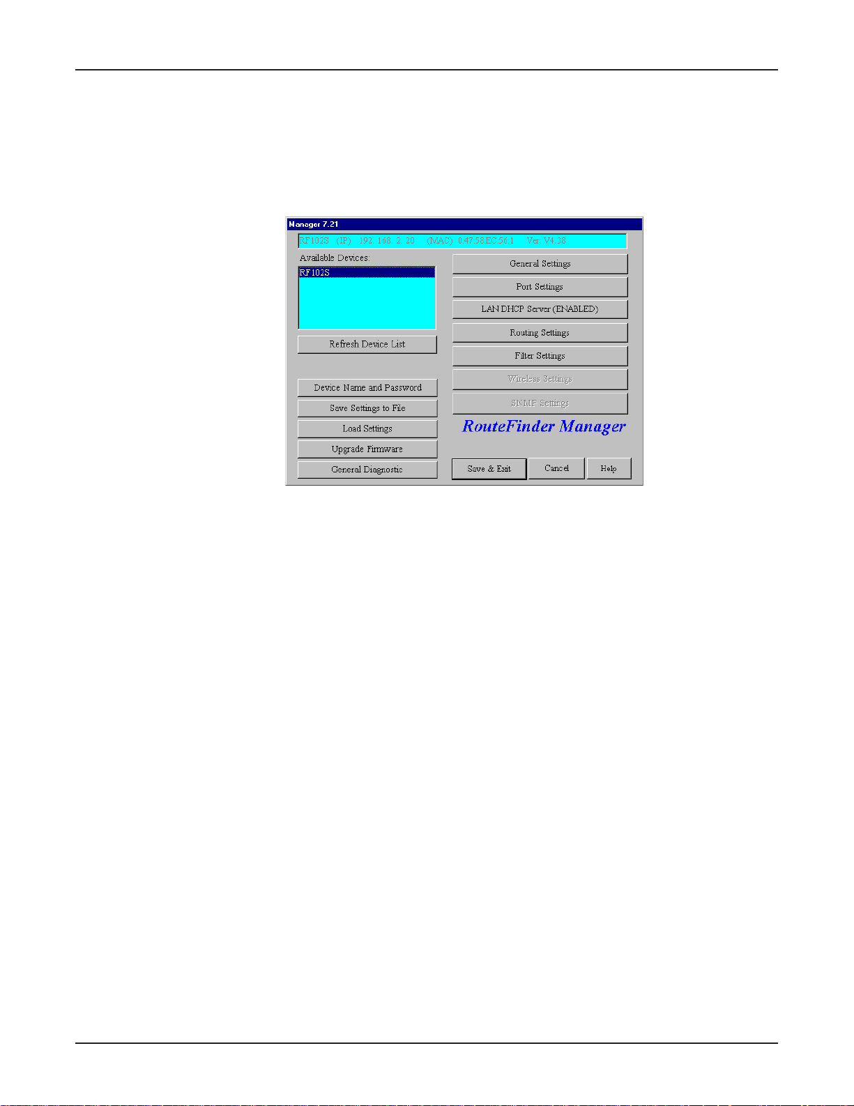
RouteFinder Manager
RouteFinder Manager is the main program used to configure all the settings of your RF102S.
1. To run RouteFinder Manager, double-click the RouteFinder Manager icon on your desktop, or
click Start | Programs | RouteFinder Manager | RouteFinder Manager.
2. The Manager dialog box displays.
Chapter 5 - RouteFinder Manager
3. The RF102S automatically searches your network for devices available for configuration and
displays them in the Available Devices list box.
Note: Before using any of the Manager options, you must select the device you are attempting to
configure from the Available Devices list. If you need to update the list, click Refresh Device
List. You must exit RouteFinder Manager before using the device.
After you have selected a device from the Available Devices list, information about the name, IP
address, MAC address, and Firmware version of your RouteFinder displays.
The buttons in the left column of the window offer the ability to change the device’s name and
password, save and load settings, upgrade the firmware, or run general diagnostics on the
device. The buttons in the right column provide access to advanced configuration options for
General Settings, Port Settings, LAN DHCP Server Options, Router Settings, and Filter Settings.
Additional information about all of these options is included in this chapter.
Note: If the IP address of the device you are attempting to configure is not within the same
subnet, the Please Set the Device IP dialog box displays, requesting you to input an IP address
in the same subnet.
Should an error message appear, refer to the Troubleshooting chapter of this User Guide.
31
Page 32
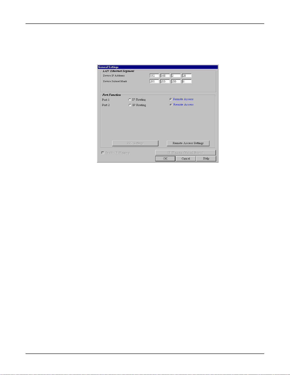
General Settings
After selecting your device from the Available Devices list, click General Settings to view or change
all of the major network settings for the RF102S including LAN Ethernet Segment, IP Routing, and
Remote Access settings. Most of these settings were entered in Setup Wizard. However, some
important settings can be entered only in RouteFinder Manager.
Chapter 5 - RouteFinder Manager
LAN Ethernet Segment
Server IP address
This IP address is the internal LAN IP address of the RF102S. The address entered into the
Setup Wizard is displayed here (for example, 192.168.2.1).
Server IP Netmask
The RF102S subnet mask generally can be left at the default value of 255.255.255.0.
Port Function
The Serial ports can be configured to provide either IP Routing or Remote Access. IP Routing is
used to connect your network to another router through one or both of the Serial ports. Remote
Access enables remote users to dial-in to the device to access and share network resources as if
they were logged on to the network locally.
1. To configure the RF102S for IP Routing, click IP Routing in the Async Port section of the
General Settings dialog box.
2. Click PPP Settings.
32
Page 33
Chapter 5 - RouteFinder Manager
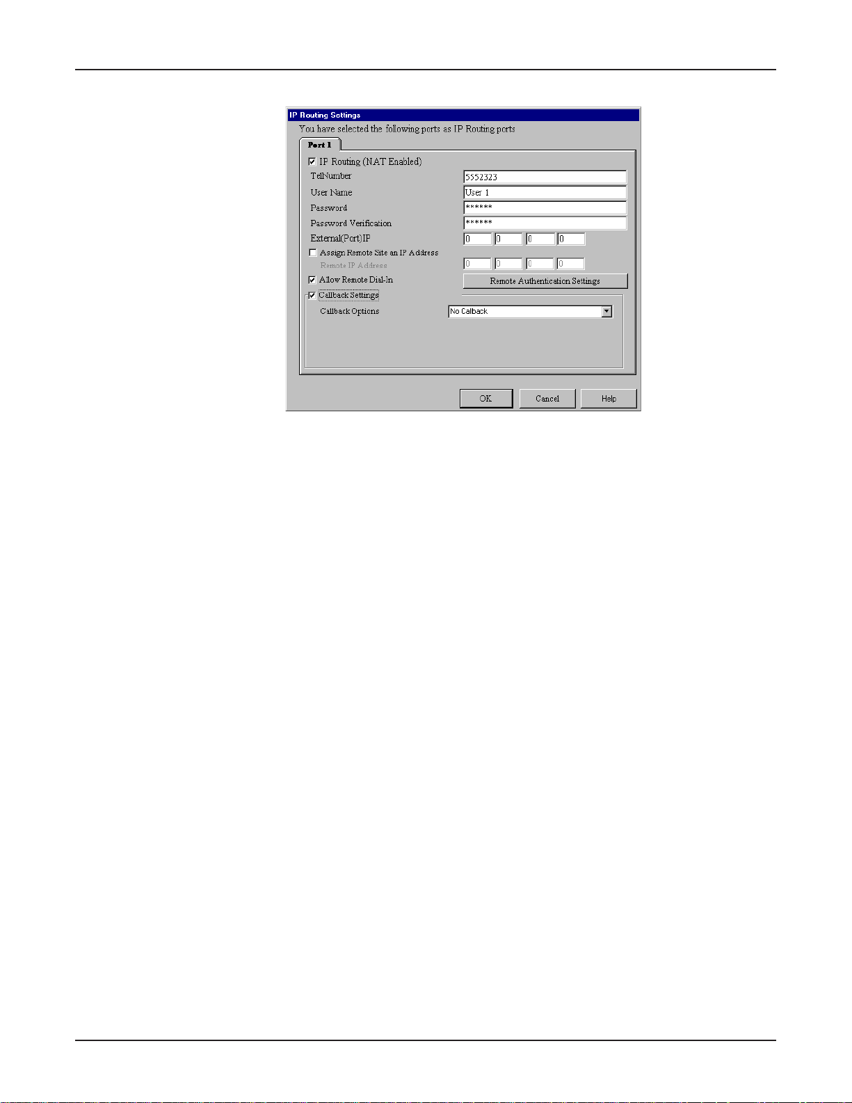
3. The IP Routing Settings dialog box displays.
IP Routing (NAT Enabled)
If NAT is enabled, all local users will be firewall protected and will share one IP address through
the Async port. Enter the information as described:
T el Number
Enter the phone number required to access your ISP.
User Name
Enter the account user name to be authenticated by your ISP.
Password
Enter the user account password to be authenticated by your ISP.
Password Verification
Re-enter the user account password for verification.
External (Port) IP
Enter the fixed IP address provided by the remote site System Administrator. If this address is
automatically assigned by the remote site DHCP server , enter 0.0.0.0
Assign Remote Site an IP Address
If you will specify the IP Address of the remote site, select this check box.
Remote IP address
Enter the IP address the remote site will use.
Allow Remote Dial-In
This option allows a remote site to dial-in to this network.
1. From the IP Routing Settings dialog box, select Allow Remote Dial-In.
2. Click Remote Authentication Settings.
33
Page 34
Chapter 5 - RouteFinder Manager
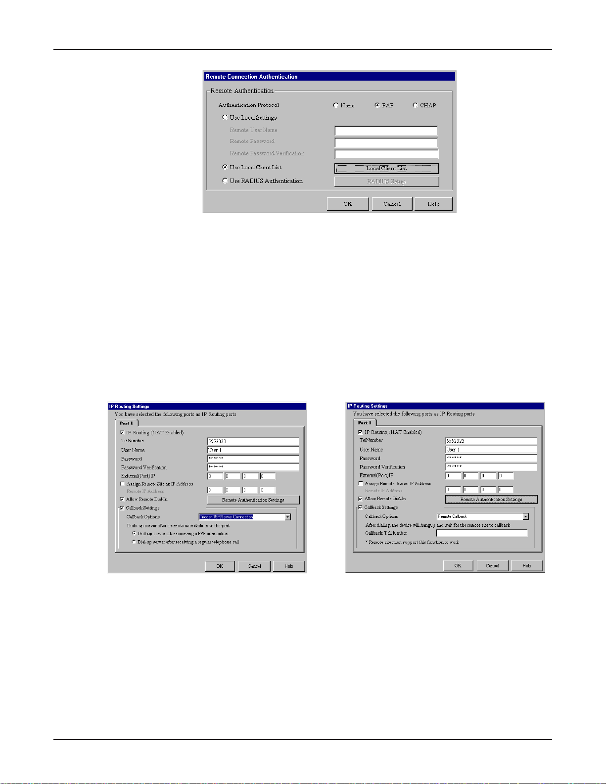
3. The Remote Connection Authentication dialog box displays.
4. You must select one of three methods to define the authentication protocol to be used when a
remote site is dialing in to your site. You may select:
• None - No authentication needed.
• PA P - User Name and unencrypted Password are transmitted over the network.
• CHAP - DHCP sends a key which is used to encrypt the user name and password. Encryption
provides added protection from potential interception of authentication information.
Note: If you select PAP or CHAP, you must indicate where the authentication process should
occur, by selecting Use Local Settings, Use Local Client List, or Use RADIUS
Authentication. Refer to Remote Connection Authentication Settings following this section.
5. Click OK when complete.
Callback Settings
From a remote site, you can trigger your RF102S to establish a connection with your ISP.
1. Click Callback Settings and select one of three call back options:
a. No Callback
b. T rigger (ISP) Server Connection - The RouteFinder will establish a connection with the ISP
server after a remote user dials into the asynchronous port. The device can be triggered
to automatically establish a connection with the ISP in one of two ways:
•The ISP server is dialed after the RF102S receives a PPP (modem) connection from a
remote user.
•The RF102S makes the connection to the ISP server after receiving a regular telephone call.
The remote user calls the RF102S async port to trigger the connection to the ISP server .
c. Remote Callback - After dialing, the RF102S hangs up and waits for the remote site to
34
Page 35
Chapter 5 - RouteFinder Manager
callback. You must enter the callback telephone number (the telephone number the
device should call) in the T el Number box.
2. Click OK to complete.
Remote Connection Authentication Settings
When you select Allow Remote Dial-in, you must determine the method that remote users must use
to be authenticated on your system. If you choose the PAP or CHAP authentication protocol, you
must select Use Local Settings, Use Local Client List, or Use RADIUS Server authentication.
Use Local Setting
You may create a Remote User Name and Remote Password to log in to the system. All users
must type the same user name and password that you specify .
Use Local Client List
The Local Client list is a list of all User Names and Passwords that can access your network from
a remote site. When a remote user dials in to the RF102S, the user’s access profile information
(user name, password, callback status, and so on) is validated by checking the user information
in this list. The RF102S can include up to 64 users in the Local Client list. Click Local Client
List to add your remote users.
Important: The RF102S is set up with a default user of guest which requires no password. For
security reasons, either delete the guest user id guest or provide it with a password.
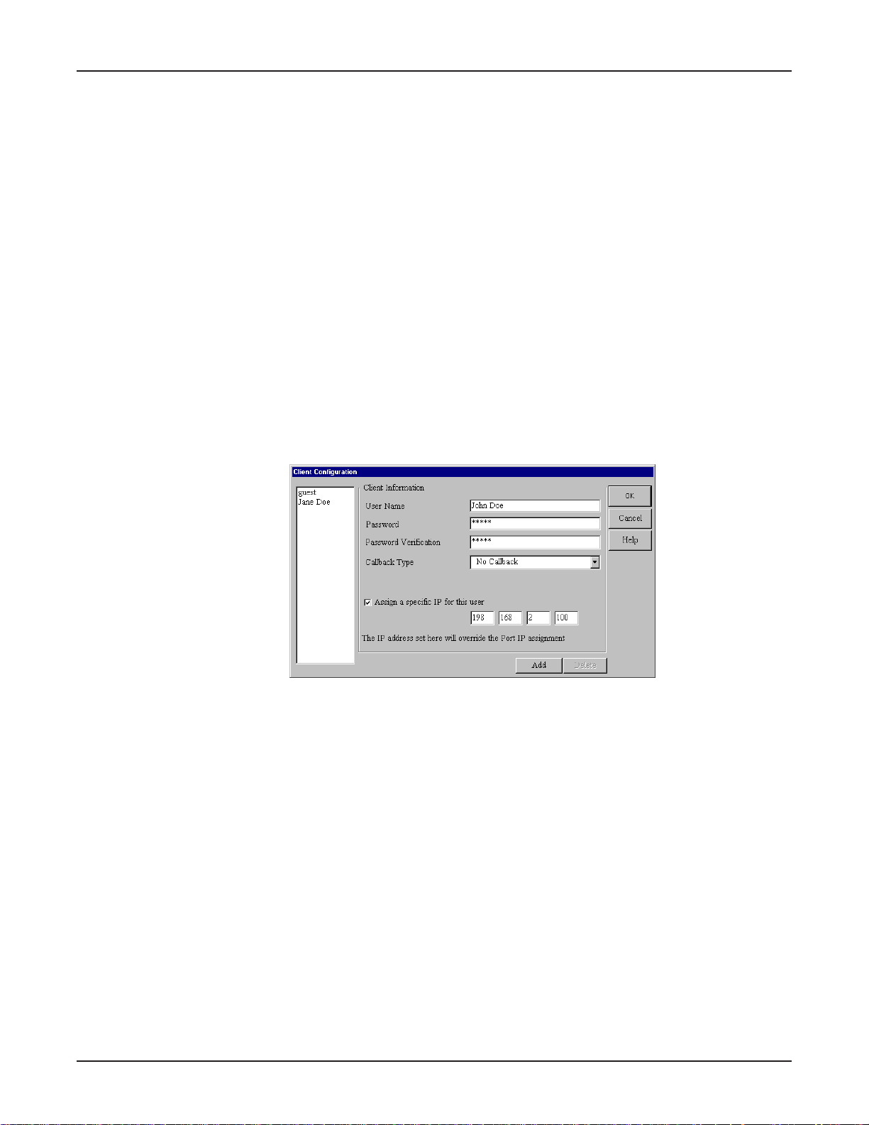
Client Information
For each new remote user added to the system, enter the following information:
User Name
Specify a user name with a maximum of 16 characters.
Password
Specify the password corresponding to the user name. Passwords are limited to 16 characters.
Password Verification
Verify the password by re-entering the user password in the box provided.
Callback T ype
The callback feature provides an added level of security to your dial in system. A remote client
dials in to the network and then disconnects. The RF102S then calls the client back. The feature
can be implemented using No Callback, Fixed Callback, or Variable Callback.
No Callback
The RouteFinder does not perform a callback function. This is the default setting.
35
Page 36
Chapter 5 - RouteFinder Manager
Fixed Callback
The RouteFinder will connect to the client by dialing the number specified in the Your
TelNumber box.
Variable Callback
This option allows the remote client to specify the phone number the RouteFinder should callback
each time a dial up connection is established.
Assign a specific IP address for this user
Select this option if you would like to have a specific IP address assigned to this user . Enter the
IP address in the field provided. This IP address will be used each time the client logs in and will
override the Assign Remote Site an IP Address option as shown in the IP Router Setting
dialog box, Async tab.
Click Add to complete adding this client to the Local Client List.
Use Radius Authentication
Choosing RADIUS Authentication allows you to use the user information (user name, password, IP
address, etc.) stored on a separate RADIUS server on the network.
Note: A RADIUS Server (Remote Authentication Dial-In Service) is an accounting and
authentication system used by many large companies and Internet Service Providers (ISPs).
After a client dials in to the network and enters their username and password, the information is
passed to a RADIUS server. The RADIUS server checks that the information is correct, and then
allows access to the system.
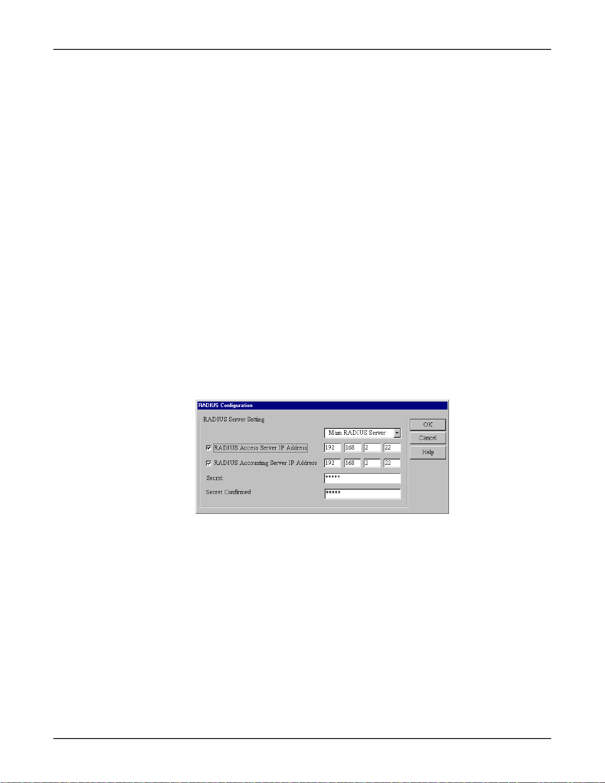
1. In the Remote Access Settings dialog box, click Use RADIUS Authentication, then click
RADIUS Setup.
2. The RADIUS Configuration dialog box displays.
3. From the list, select the Main or Backup RADIUS Server from which the device will be
authenticated.
4. Enter the IP Address of the RADIUS Access Server and the RADIUS Accounting Server IP
Address.
Note: In most cases, the RADIUS Accounting Server and the Access server are the same
device. If this is true for your configuration, enter the same IP address in both boxes.
5. In the Secret box, enter your Secret RADIUS code or password. In the Secret Confirmed box,
re-enter your Secret RADIUS code.
6. Click OK when complete.
36
Page 37
Chapter 5 - RouteFinder Manager
Remote Access - Remote Access Settings
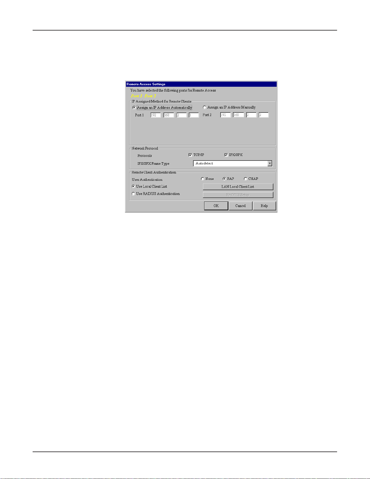
1. From the General Settings dialog box, select Remote Access and click Remote Access
Settings.
2. The Remote Access Settings dialog box displays.
IP Assigned Method for Remote Clients
A remote client must have an IP address to connect to the network. IP addresses may be
assigned automatically from a designated IP address pool using DHCP, or the IP address may be
manually assigned.
Assign an IP Address Automatically
The DHCP feature will issue the remote site user an IP address automatically if the DHCP
function is enabled. If DHCP is disabled, the device will automatically search for a DHCP server
and request an IP address for the remote client.
Assign an IP address manually
Enter an IP address for the remote client.
Network Protocols
You must select the network protocols you would like to enable for the dial-in service. The
default enables both TCP/IP and IPS/SPX. If you do not need both protocols, you may disable
one of them. If you are connecting to a Netware Server, IPX/SPX must be enabled.
IPX/SPX Frame Type
The RouteFinder RF102S can automatically detect what kind of IPX/SPX frame type you are
using. You may manually select a frame type by using the list box.
Remote Client Authentication
Remote authentication settings allow you to specify how you would like to authenticate remote
users. You may select Use Local Client List or Use RADIUS Authentication (refer to Remote
Connection Authentication Settings in this chapter for more information). Choosing RADIUS
configuration allows you to use the user information (user name, password, IP address) stored
on a separate RADIUS server on the network.
3. Click OK when complete.
37
Page 38
Chapter 5 - RouteFinder Manager
Enable IP Mapping - Virtual Server
IP Mapping is available only when NAT is enabled. If NA T is enabled for a particular port, that port is
firewall protected. The Enable IP Mapping function allows you to open a “hole” in your firewall to
allow access to your LAN via the Internet. For example, you can use the IP mapping function to
access an FTP server on your LAN via the Internet. IP Mapping is most suitable to fixed or static IP
addressing.
1. To enable IP Mapping, from the General Settings dialog box, select the Enable IP Mapping
check box, then click IP Mapping (Virtual Server).
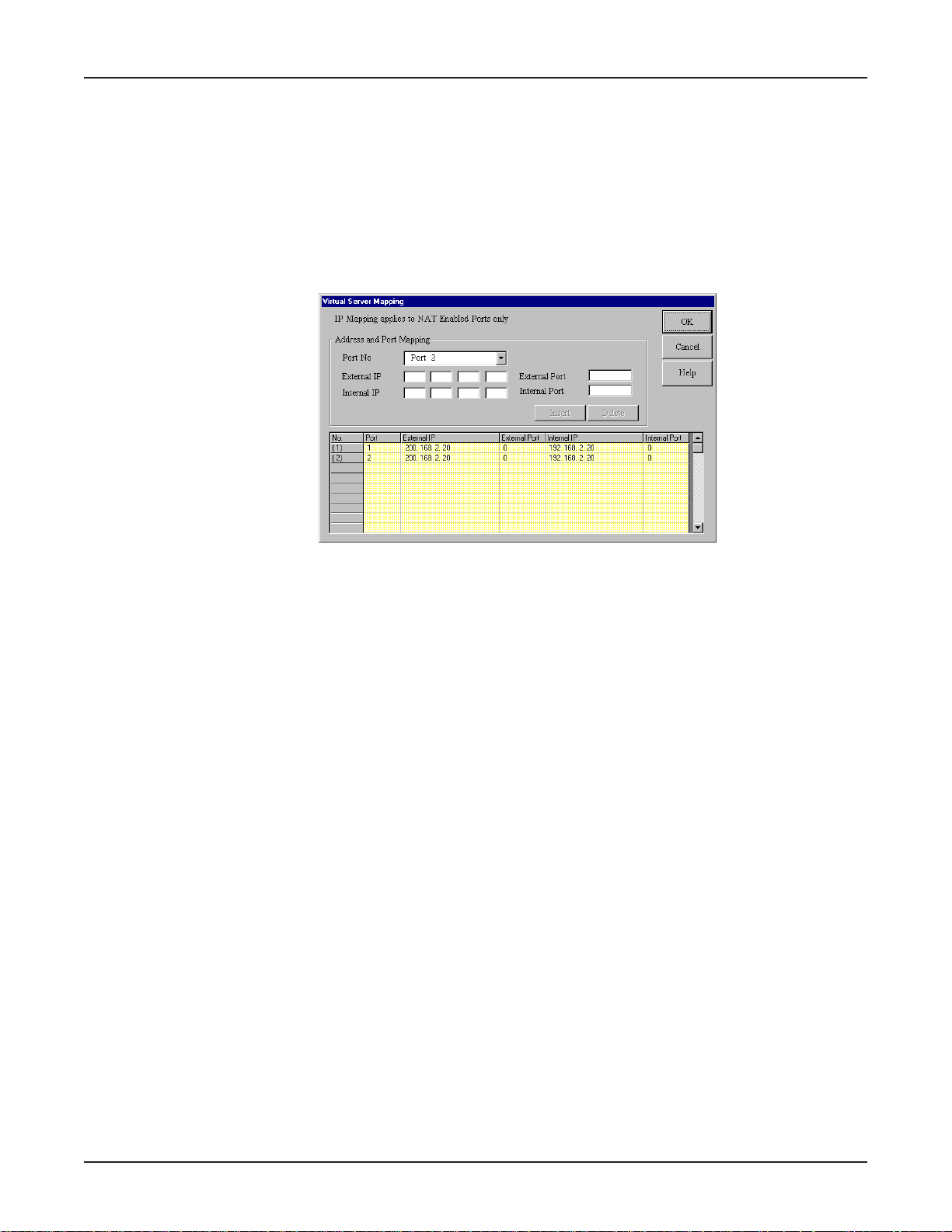
2. The Virtual Server Mapping dialog box displays.
For each service you want to set up, do the following:
1. From the Port No box, select Port 1 or Port 2.
Note: If you are using one of the Serial ports for Remote Access, you cannot select that port.
2. Enter the IP address supplied by your ISP in the External IP box. If your ISP uses dynamic IP
addressing, enter 0.0.0.0. Your device will use the dynamically assigned address when
connecting to your ISP.
3. Enter the TCP/IP port number for the service that you will be using for IP mapping. Common
TCP/IP port numbers are listed below:
WWW Port 80
FTP Port 20 or 21
SMTP Port 25
POP3 Port 110
For more information on port numbers, visit http://www.metadigm.co.uk/
If you would like to map all services for this external IP address to a computer on your LAN, you
can enter port number 0. This means that whenever anyone accesses your external IP address,
they will automatically be “mapped” to the internal computer that you specify , regardless of what
port number they are using.
4. Enter the Internal IP address of the server to which you want to map the External IP address.
5. Enter the port number for the service that you will be using for this IP mapping.
Click Insert to include the mapping.
6. Click OK when you have completed mapping addresses.
Note: IP Mapping function allows you to have only one port service on your LAN. For example, if
you map an external IP (16.895.1.3) to an internal IP address (192.168.2.22 - a www server),
only the internal IP address in your local network can serve as the www.server for the external IP
address.
38
Page 39
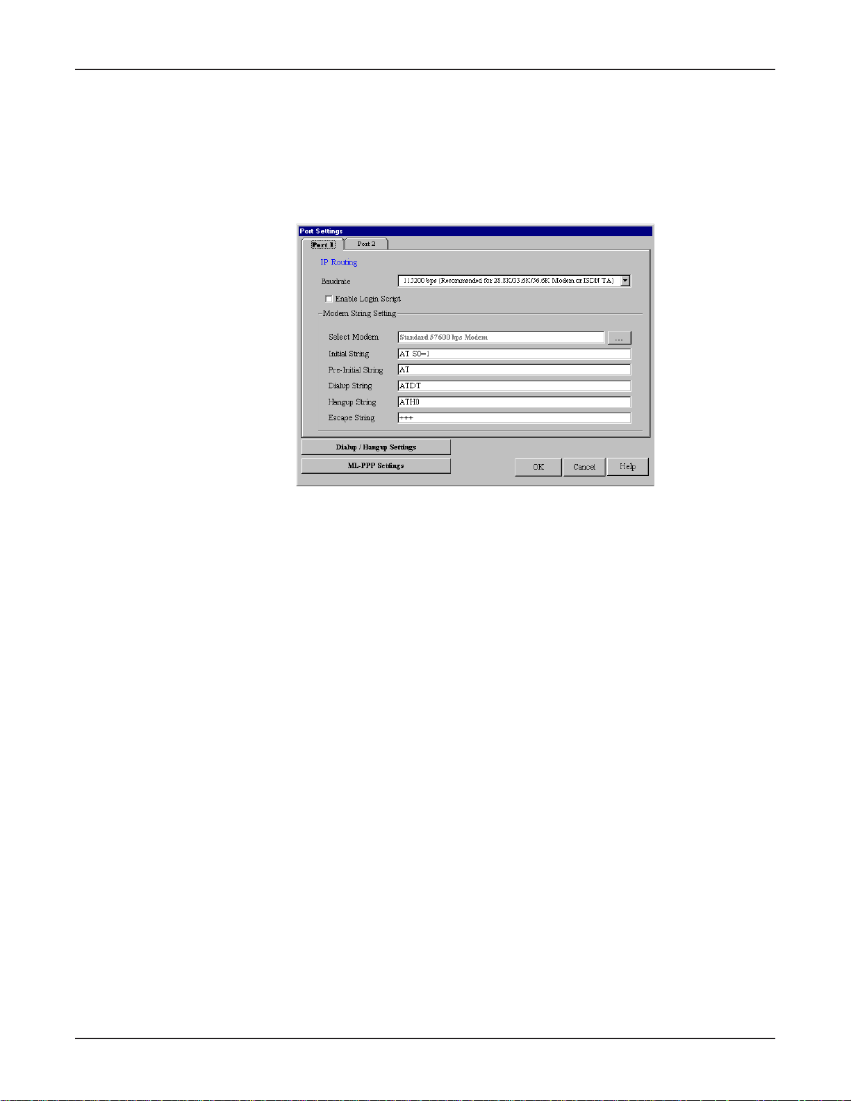
Port Settings
The Modem Settings options are used to configure the communication between your modem or ISDN
T A and your RouteFinder serial port. You must specify the baudrate, modem, and modem string
settings for your device.
1. To view or change the port settings, from the main Manager dialog box, click Port Settings. The
Port Settings dialog box displays.
Chapter 5 - RouteFinder Manager
2. Complete the information as follows:
Baudrate
Use the list to select the Remote Access DTE speed for your device.
The absolute maximum setting for a given port on the network device is 4 times the speed of
your modem. If the baudrate is set too high, your network device may fail to establish a dial-up
connection. For example, if you have a 14.4Kbps modem, the highest speed selected is
57.6Kbs.
If your modem does not appear in the list provided, the Standard Modem selection will work in
most cases.
Important: If you are using an ISDN Terminal Adapter , refer to the Async to Sync PPP string in
the User Manual provided with the device to determine the correct initialization, dialup and hang
up strings.
Note: Due to variations in ISP connections and phone line quality, this theoretical maximum
speed is not attainable. You may need to set the baudrate at a lower speed.
39
Page 40
Chapter 5 - RouteFinder Manager
Edit Login Script for Remote Access
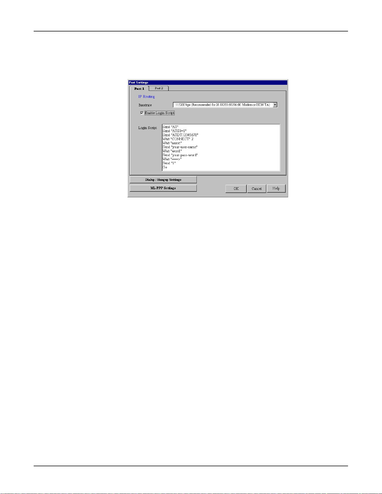
1. To edit the login script for remote access, in the Port Settings dialog box, select the Enable
Login Script check box.
2. The login Script dialog box displays.
A sample remote access login script is shown below. If a remote access client is configured to
“bring up a terminal window after dialing”, this remote access login script initiates.
For Remote Access, the device will act as the server side.
Send ‘Welcome’ displays “Welcome” to remote site.
Send sends an Enter (Carriage return + line feed) to the remote site.
“Send Username” prompts the remote site for a user name.
“Retrieve 1” will wait for the remote site to enter the user name that will be used for PPP
authentication.
“Send Password” prompts the user for a password.
“Retrieve 2” will wait for the remote site to enter a password.
“Verify 3” instructs the device move to login script line 3 if PPP authentication fails.
“Go” means start PPP protocol.
Writing a login script for IP Routing
To write an effective login script, you must obtain the correct login script information from your ISP
and become familiar with using the login script commands.
Every ISP has a unique login interface screen. Check with your ISP to determine how your ISP
requests information from you when using a PPP connection.
Note: You can create a simple dial-up connection to view your ISP interface log-in screen using DialUp Networking in Windows 95, 98, NT or 2000.
Some common commands are:
Send and SH FUNCTION
Send ‘A TZ’ Resets the Modem
Send ‘A TDT 888-1234’ Dials the phone number “888-1234”
Send ‘JaneDoe’ Types “JaneDoe” at the ISP interface
SH ‘1234’ Types “1234” at the ISP interface but displays **** on the RouteFinder
monitor to hide the password.
Send ‘’ Sends Enter (carriage return plus line feed) to the ISP
Wait FUNCTION
40
Page 41

Chapter 5 - RouteFinder Manager
Wait 5 The Modem will wait for 5 seconds before moving the next line in the
login script.
Wait ‘CONNECT’ The Modem will wait for CONNECT to display before moving to the next
command.
Wait ‘CONNECT 6’ Modem will wait for “CONNECT” to display before moving to the next
command. If CONNECT does not display, the modem will go to line 6 of
the login script.
Other FUNCTION
Go Begins PPP
Jump4 Goes back to line 4 of the login script.
Hangup Hangs up the modem.
Example 1: Script for Normal Reliable ISP
# Login Script Meaning of Each Login Script Command
1 Send‘ATZ‘ Rests Modem
2 Send‘ATS0 =1‘ Sends initial string ‘ATS0 =1‘ to modem
3 Send‘ATDT888-1234‘ Dial phone number 888-1234
4 Wait‘CONNECT‘ Waits for ISP to send reply ‘CONNECT‘
5 Wait‘username:‘ Waits for ISP to send reply ‘username‘
6 Send‘JaneDoe‘ Sends the user name ‘JaneDoe‘ to the ISP
7 Wait‘password‘ Waits for ISP to send reply ‘password‘
8 SH‘1234‘ Sends password ‘1234‘ to the ISP
9 Wait‘===>‘ Waits for ISP to send reply ‘===>‘
10 Send‘1‘ Selects option 1(PPP) for this ISP
1 1 Go Starts PPP mode
Example 2 : Script for Unreliable ISP (Redial until connected)
# Login Script Meaning of Each Login Script Command
1 Send‘ATZ‘ Resets modem
2 Send‘ATS0 =1‘ Sends initial string ‘ATS0 =1‘ to modem
3 Send‘ATDT8881234 Dials phone number 888-1234
4 Wait‘CONNECT‘2 Wait for ISP to send reply ‘CONNECT‘. If no CONNECT, returns
to line 2 to re-dial.
5 Wait‘username:‘12 Waits for ISP to send reply ‘username‘. If no response, goes to
line 12.
6 Send‘JaneDoe‘ Sends the username ‘JaneDoe‘ to the ISP
7 Wait‘password‘ Waits for ISP to send reply‘ password‘
8 SH‘1234‘ Sends password ‘1234‘ to ISP
9 Wait‘====>‘ Waits for ISP to send reply ‘===>‘
10 Send‘1‘ Selects option 1 (PPP) for this ISP
1 1 Go Starts PPP mode
12 Hangup Hangs up Modem
Example 3 : Script for Unreliable ISP (2nd ISP backup)
# Login Script Meaning of Each Login Script Command
1 Send‘ATZ‘ Resets modem
2 Send‘ATS0 =1‘ Sends initial string ‘ATS0 =1‘ to modem
3 Send‘ATDT8881234 Dials phone number 888-1234
4 Wait‘CONNECT’ 12 Waits for ISP to send reply ‘CONNECT’. If no reply, goes to line
12 for ISP #2.
5 Wait ‘username:’ 12 Waits for ISP to send reply ‘username’. If no response, goes to
line 12 for ISP #2.
6 Send‘JaneDoe‘ Sends the username ‘JaneDoe‘ to ISP
7 Wait‘password‘ Waits for ISP to send reply‘ password‘
8 SH‘1234‘ Sends password ‘1234‘ to ISP
9 Wait‘====>‘ Waits for ISP to send reply ‘===>‘
10 Send‘1‘ Selects option 1 (PPP) for this ISP
41
Page 42
Chapter 5 - RouteFinder Manager
11 Go Starts PPP mode (Rest of script ignored)
12 Hangup Hangs up Modem
13 Send ‘AT S0=1’ Sends initial string ‘A T SO=1’ to modem
14 Send ‘ATDT 8885678’ Dials phone number 888-5678 (ISP #2)
15 Wait ‘Connect’ 23 Waits for ISP to send reply ‘CONNECT’. If no CONNECT, goes
to line 23.
16 Wait ‘username:’ 23 Waits for ISP to send reply ‘username’. If no response, goes to
line 23.
17 Send ‘Stephen’ Sends the username ‘Stephen’ to ISP
18 Wait ‘password:’ Waits for the ISP to send ‘password:’
19 SH ‘5678’ Sends password ‘5678’ to ISP
20 Wait‘====>‘ Waits for ISP to send reply ‘===>‘
21 Send‘1‘ Selects option 1 (PPP) for this ISP
22 Go Starts PPP mode
23 Hangup Hangs up Modem
24 Jump 2 Goes back to line 2 to re-dial ISP#1
Modem String Settings
The most important modem string is the initialization string because your network device uses it to
establish communications with your modem or ISDN TA. The modem initialization string displayed is
the modem or ISDN TA initialization string entered in the Setup Wizard. For most analog modems,
the Standard Modem selection will work. For additional information, refer to the Modem Settings
information presented in the Software Installation and Configuration Chapter of this User Guide.
Important: There is no standard ISDN TA initialization string. If your ISDN TA is not included in the
modem list, check your ISDN TA User’s Guide for information for the initialization string for an
Asynchronous to Synchronous PPP connection. If you are using only one channel of your ISDN
connection, you can enter the Async to Sync PPP initialization string. If you are bundling your
connection channels, you will need to use a Multilink-PPP initialization string. You must also enter
the two phone numbers in the General Settings dialog box. Also verify that your ISDN TA supports
the dial-up string ATDT . Most ISDN TAs support ATDT, but some support ATD or A TDI.
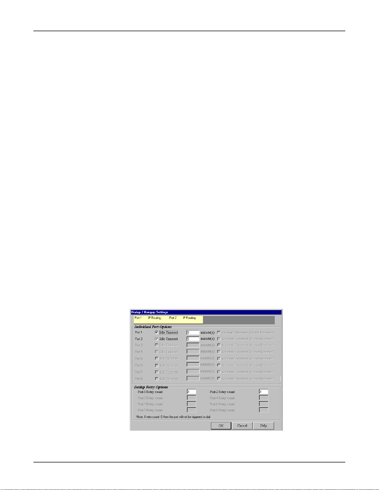
Dial-up/Hang-up Settings
The Dial-up/Hang-up settings allow you to specify your connection time (idle timeout or auto
reconnect) and the number of times to attempt to connect (if connection cannot be established).
1. From the main Manager dialog box, click Port Settings.
2. Click Dial-up/Hang-up Settings. The Dial-up/Hang-up Settings dialog box opens.
42
Page 43
Chapter 5 - RouteFinder Manager
Individual Port Options
Individual Port Options lets you set the idle-timeout function for each serial port of the RouteFinder.
You can set the number of minutes you want to allow a connection to stay idle before disconnection.
The default idle timeout for IP Routing is 5 minutes. The default idle timeout for Remote Access is 0
minutes.
If you clear the Idle Timeout check box, once a client establishes a connection, the connection will
be maintained until you turn off your modem, unplug your network device or click Terminate
Connection in the RouteFinder monitor program.
The Automatic Reconnect (Always connect) essentially maintains your connection (for example, idle
time out = infinite). If the connection is disconnected for any reason, it will automatically attempt to
reconnect.
Dial-up Retry Options
The Dial-Up Retry option allows you to specify the number of times the RouteFinder should attempt
to establish a connection. If the retry count is 0, the device will not dial-out to connect to the remote
site. Automatic Reconnect will override the Retry count setting if retry count is set to 0.
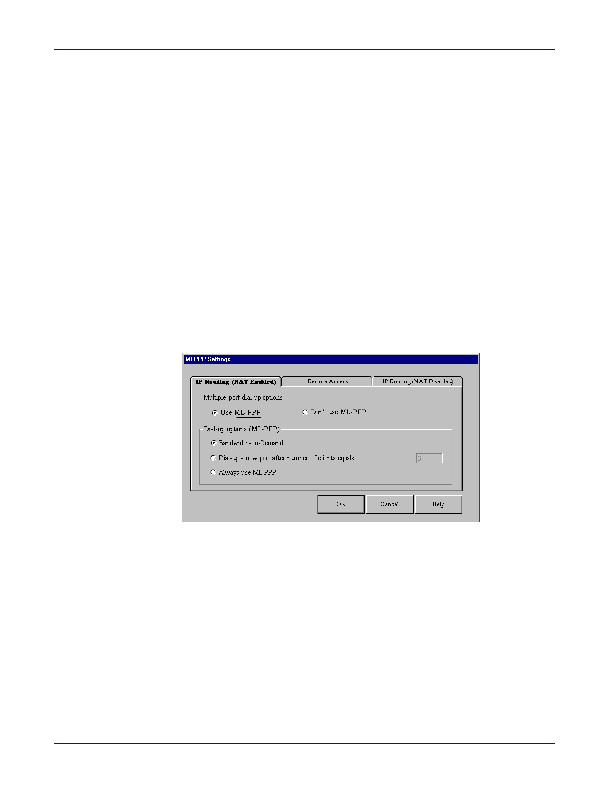
ML-PPP Settings
ML-PPP is a protocol that will widen your bandwidth by connecting two or more lines. You can
connect two modems to your two ports and double the bandwidth. ML-PPP bundles packets as
though the two connections are one larger bandwidth connection.
If you select the Use ML-PPP option, select one of the following:
Bandwidth on Demand
When traffic becomes heavy, this option triggers the second line using ML-PPP.
Dial-up a new port after number of clients equals
The network device dials a new port when the number of users exceeds the number entered.
Always use ML-PPP
The network device always uses the ML-PPP protocol regardless of the number of users.
43
Page 44
Chapter 5 - RouteFinder Manager
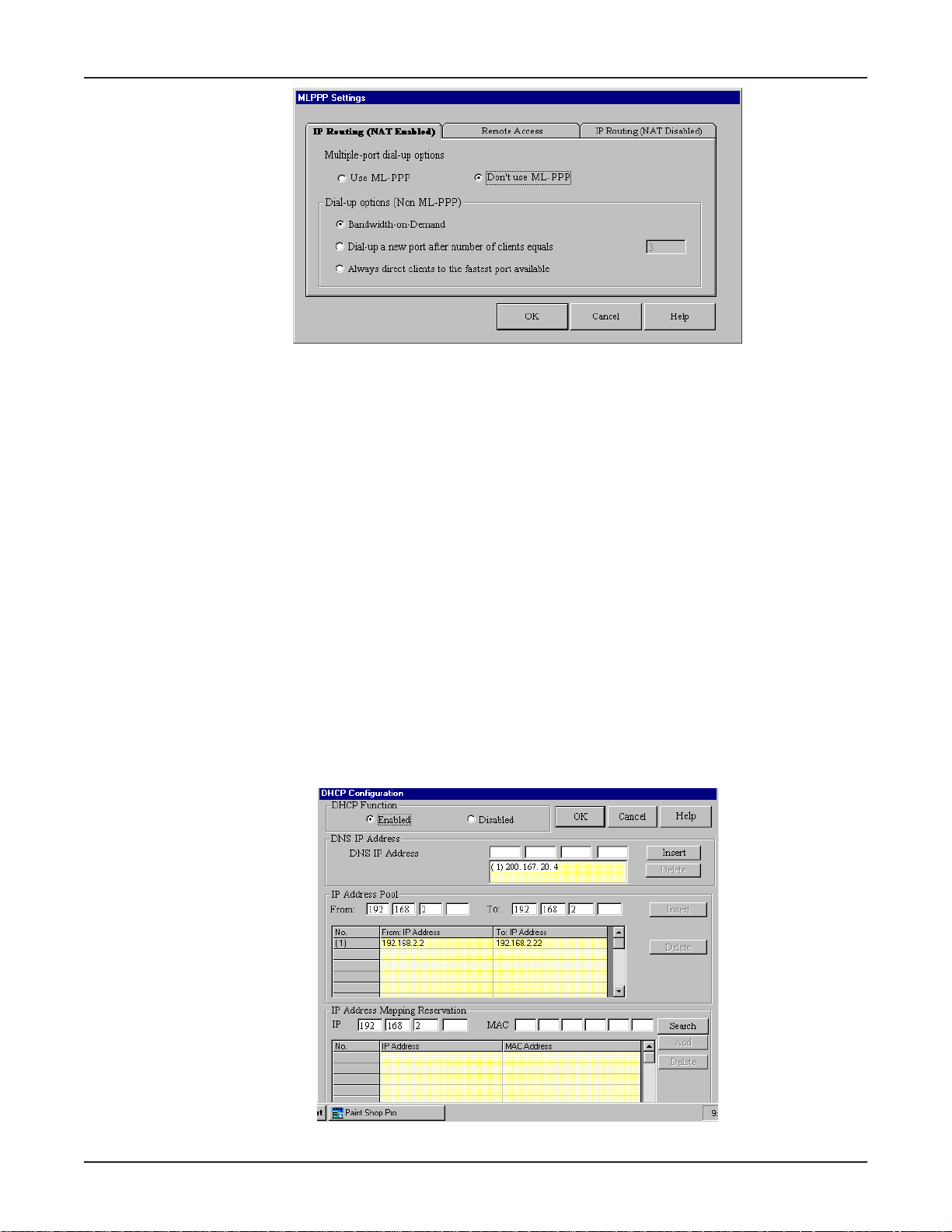
If you select the Use ML-PPP option, select one of the following:
Bandwidth on Demand
When traffic becomes heavy, this option looks for other routes to relieve the load, such as another
connection to an ISP (without ML-PPP).
Dial-up a new port after number of clients equals
The network device dials a new port when the number of users exceeds the number entered.
Always direct clients to the fastest port available
The network device determines which port is least busy and directs clients to that port.
LAN DHCP Server
Refer to the Glossary at the back of this User Guide for more information about the DHCP function.
1. From the main Manager dialog box, click LAN DHCP Server.
Note: The LAN DHCP Server option indicates if DHCP is enabled or disabled. The DHCP
function is Enabled by default. To Disable the function, you must open the DHCP Configuration
dialog box, select Disabled and click OK.
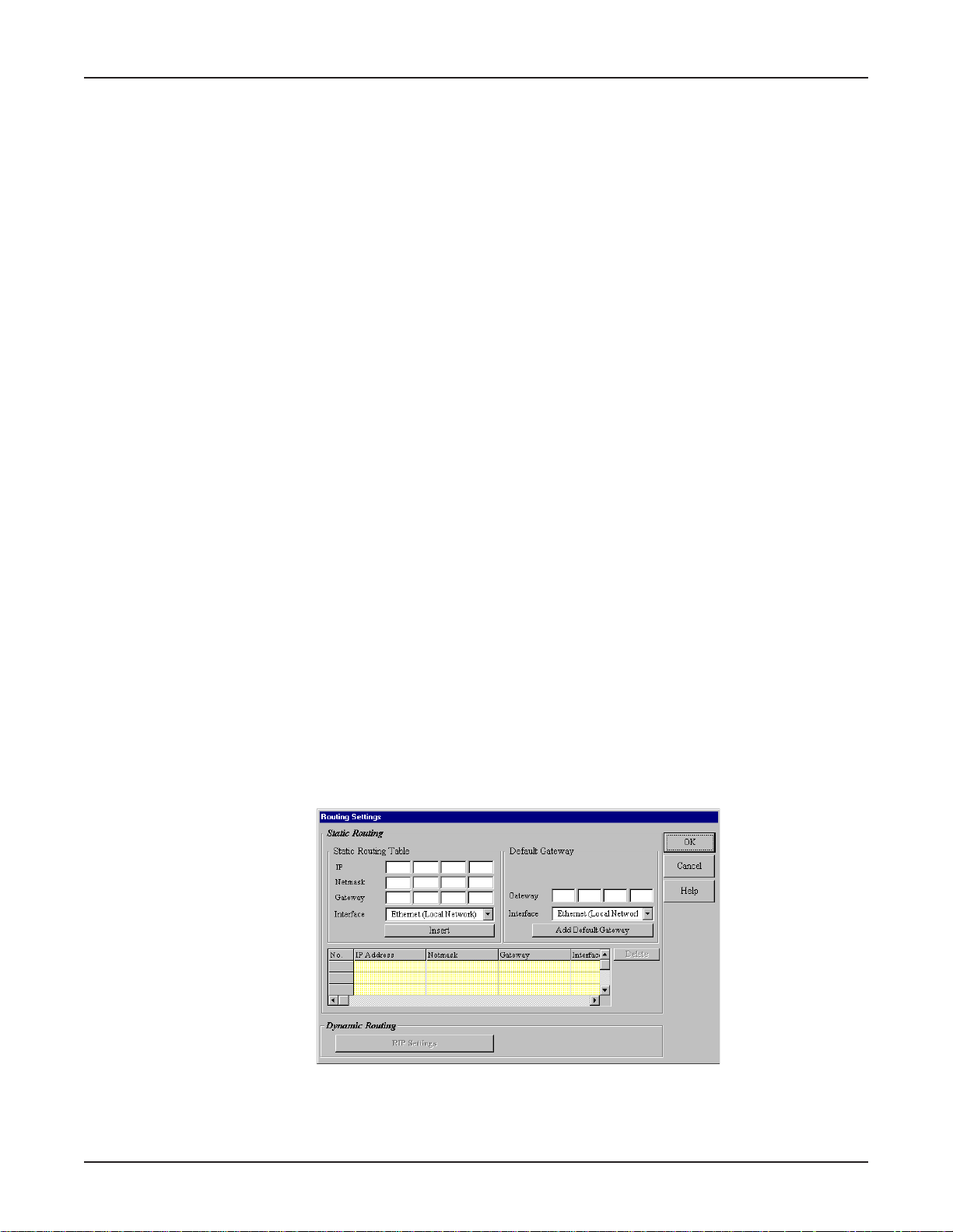
2. The DHCP Configuration dialog box displays.
44
Page 45
Chapter 5 - RouteFinder Manager
3. Complete the following information:
DNS IP Address
Enter the ISP’s DNS IP address. You may enter up to 4 ISP DNS IP addresses. Click Insert.
IP Address Pool
The IP Address Pool contains the range of IP addresses that will be automatically assigned to the
clients of your network as they connect to the network. By default, the IP address pool range is
from 100 to 200. Ranges are listed in the IP Address Pool table.
To change the range, select the existing range of addresses. Enter a new range. Press Insert.
To delete an IP Address range, select the range of addresses. Press Delete.
IP Address Mapping Reservation
You can use the IP Address Mapping Reservation option to give a static IP address to particular
computers on your network. Each time a computer is powered on and connects to the network, it
will receive the same IP address. Static IP addresses are frequently assigned to network
resources such as printers, servers, hubs and routers that are consistently shared by network
clients.
To assign a static IP Address, enter the MAC address manually or use the MAC address search
tool. To use the MAC address search tool, enter the IP address of the computer. Click Search to
find the MAC address. Once the address has been located, click Add to reserve the address.
To delete a static IP Address, select the static address you want to delete. Click Delete.
Refer to the User Guide Glossary for information about determining a computer’s netmask
address.
Routing Settings
Routing is the process of moving a packet of data from source to destination. The RF102S acts as a
router to enable messages to pass from one computer to another and eventually reach the target
machine. Part of this process involves analyzing a routing table to determine the best path. Use the
information below to create a routing table to connect your network to another network, or to connect
subnets within your network.
Note: A routing table is required to use the LAN -to- LAN routing function of the RF102S.
1. From the main Manager dialog box, select Routing Settings.
2. The Routing Settings dialog box displays.
45
Page 46

Chapter 5 - RouteFinder Manager
Static Routing
For each different subnet on your LAN, enter:
IP: Enter the (network/subnet) IP address to which you want to route.
Netmask: Enter the subnet mask of your Network IP address.
Gateway: Enter the IP address of the gateway device linking your network to the
other network/subnet. The IP address should be in the same subnet as
your RF102S. If you are using this device with the LAN-to-LAN
function, the gateway IP should be set as the IP address of the
RouteFinder.
Interface: Select the port (only local network) that the routed packet should pass
through. Select Local Network if you are using a separate router. If
you are using the RF102S with the LAN-to-LAN function, the Interface
should be set as the WAN port that connects you to the other subnet.
Click Insert to save the information to the routing table. To delete this
information, select it from the routing table and click Delete.
Default Gateway: Default gateway is an IP address that all packets are routed to, when
the device is unable to find a route match (the destination IP address of
the packet in the routing table).
Click Add Default Gateway to save the IP address of the default
gateway.
Interface: Select the port (only local network) interface where the gateway is
located.
Routing Table
The routing table stores the routing information so that the RF102S knows how to route the IP
packets to the proper network.
What is the purpose of the routing table?
In the diagram above, the RF102S-1 has the routing information to route between 192.168.3.x
and 192.168.5.x. The device does not have the information about how to route to the 172.168.2.x
network. If you want the RF102S-1 to route to 172.168.2.x, you must add the following
information to the routing table:
IP: 172.168.2.0
Network: 255.255.255.0
Gateway IP: 192.168.5.254
Interface: Ethernet (Local Network)
46
Page 47
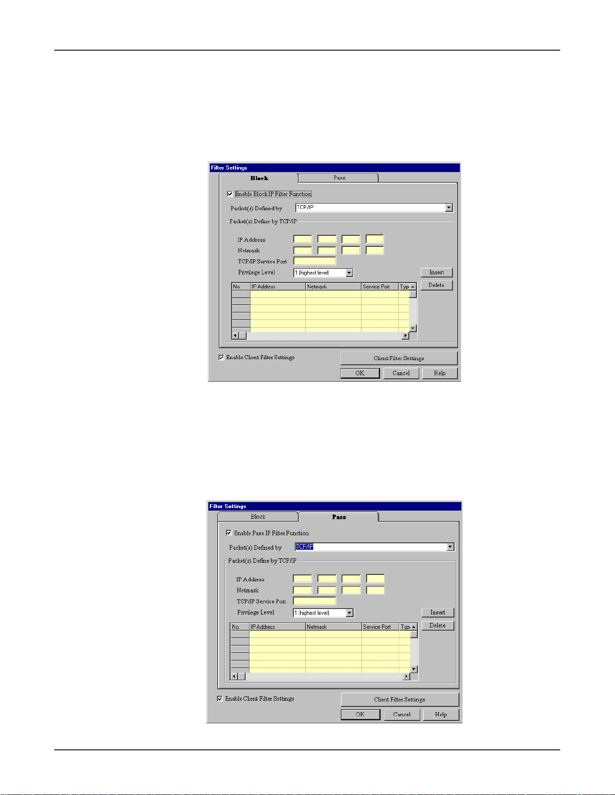
Chapter 5 - RouteFinder Manager
Filter Settings
You can use Filter Settings to choose which packets are allowed to enter the network and which
packets will be blocked. Filter Settings can be used to filter network services such as Mail, WWW,
FTP, Telnet and News.
1. From the main Manager dialog box, select your RF102S, then Filter Settings.
2. The Filter Settings dialog box displays.
3. Select the Block tab or the Pass tab to define your filtering.
• The Block function filters by blocking packets from going out the WAN port or coming in through
the LAN port. To enable the Block IP filter function, select the Enable Block IP Filter Function
check box.
• The Pass function filters by defining which packets can go into your WAN port or come on to
your LAN. To enable the Pass IP filter function, click the Pass tab and select the Enable Pass IP
Filter Function check box.
47
Page 48
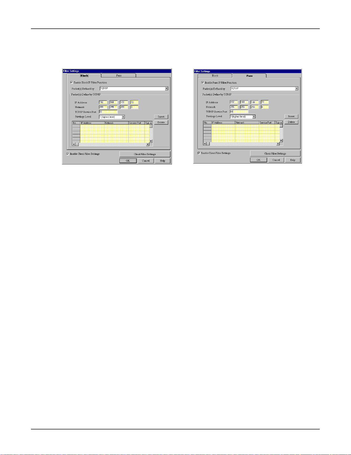
Chapter 5 - RouteFinder Manager
4. To filter packets to be passed or blocked, select TCP/IP or User from the Packets Defined by
list.
Packets Defined by TCP/IP
If you choose to define by TCP/IP, you must enter the packet IP information.
IP Address
Enter the IP address of the packet to be Blocked or allowed to Pass.
Netmask
Enter the subnet mask for the packet.
TCP/IP Service Port
Enter the Socket Port you would like to block or allow to pass (for example, HTTP= 80)
Privilege Level
From the Privilege Level box, select an appropriate level for this filter.
It is common to set many filter rules for a particular client. At times, the rules you have set may
conflict with one another. When a conflict occurs, the filter with the higher privilege level will override
the other filters. Level 1 is the highest level, level 16 is the lowest privilege level.
Example:
You configure a filter rule for IP address 192.168.100.72 with a privilege level of 16 to Pass using
socket number 80. At the same time, you set the same filter rule to block IP Address 192.168.100.72
with a privilege level of 1. The RF102S will implement the filter to block the IP address
192.168.100.72 because the privilege level is higher. If conflicting rules have the same privilege
level, the RF102S blocks the packet.
Click Insert to add each IP address to the list. To remove a defined packet, select the packet you
want to delete from the table and click Delete.
48
Page 49
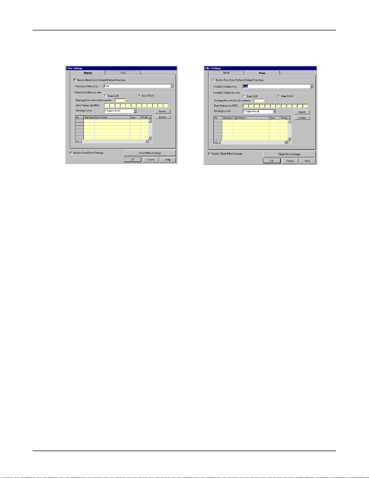
Chapter 5 - RouteFinder Manager
Packets defined by User
If you choose to define by User, you must define the byte pattern of the packets. The RF102S
uses the defined byte patterns to block or pass packets from the WAN or from the LAN.
1. In the Block tab, select the Enable Block User Defined Pattern Function check box.
2. In the Packets defined by User area, select From LAN or From WA N.
Starting from which byte number
Enter the first byte in the packet the RF102S should read to determine if the byte pattern (in Hex)
is one that should be filtered. Exclude the PPP header . Start from byte 0 of the network
protocol.
Byte Pattern (in Hex)
Enter the packet byte pattern that you would like the RF102S to recognize as a packet to be
filtered. (Block/Pass from the WAN to the LAN). The maximum pattern size is 12 bytes.
Click Insert to add each byte pattern to the table.
To delete a defined packet, select the packet in the table and click Delete.
49
Page 50
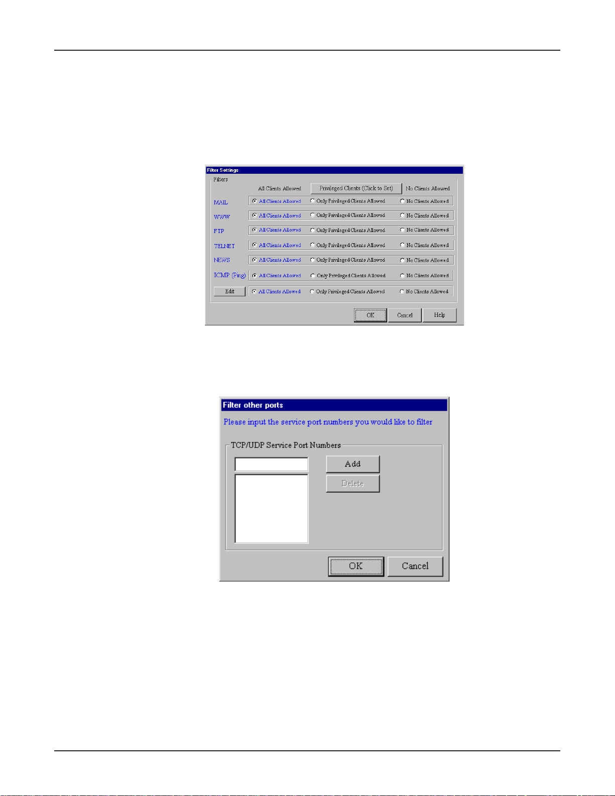
Chapter 5 - RouteFinder Manager
Enable Client Filter Settings
The Client Filter allows you to decide which services are allowed into your network and which clients
are authorized to access them.
1. From the Filter Settings dialog box, select Enable Client Filter Settings.
2. Click Client Filter Settings.
3. The Filter Settings dialog box displays.
The filter works by filtering TCP/IP port numbers. The 5 most commonly used port numbers are
listed for you. They include the port numbers for Mail, WWW , FTP, Telnet, and News. If you
would like to filter other services, you must know the port number for the service.
4. Click Edit to enter new service port numbers.
5. Enter the TCP/UDP Port Number and click Add.
6. Click Privileged Clients.
7. The Privileged Client Table dialog box displays.
50
Page 51
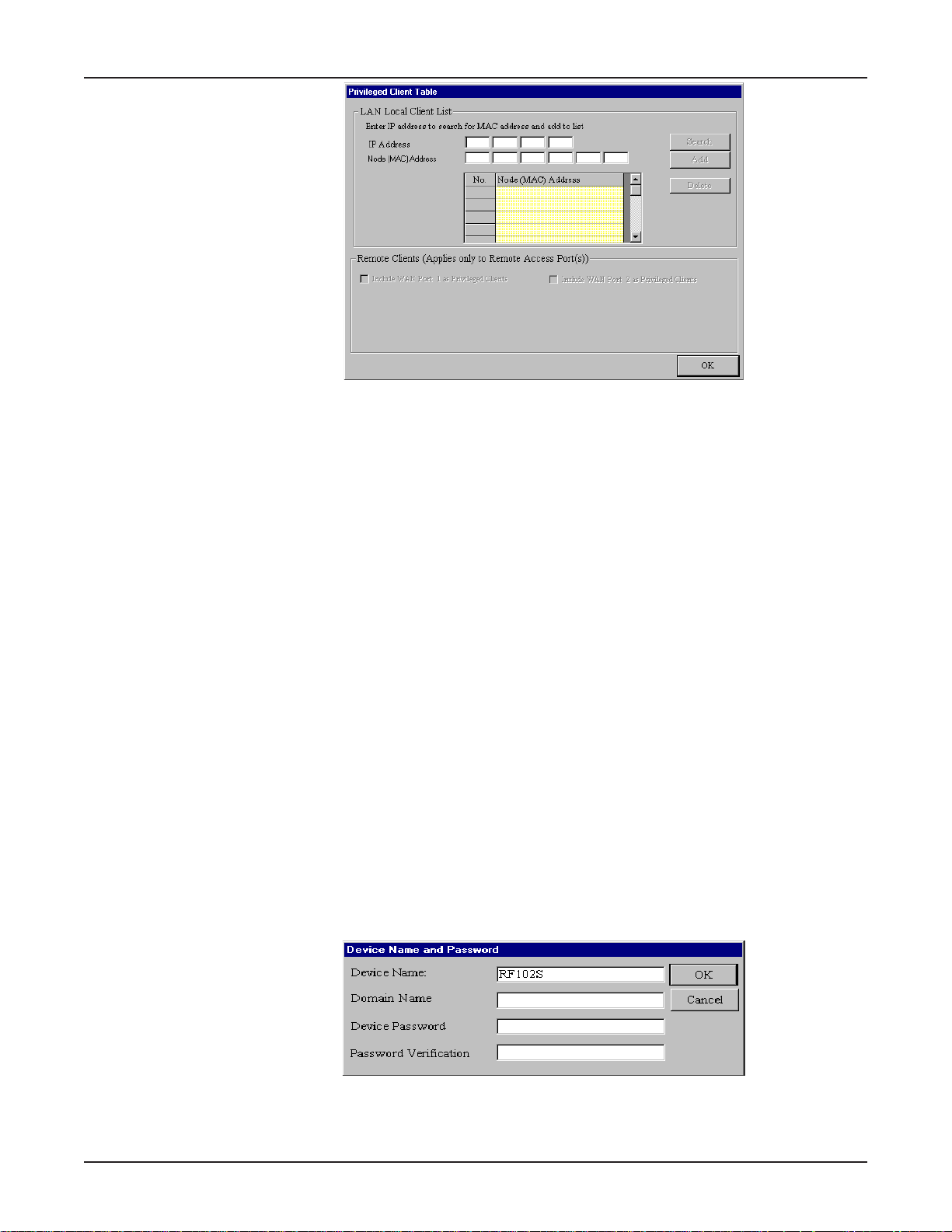
Chapter 5 - RouteFinder Manager
LAN Local Client List
In the Privileged Client Table, enter the clients you wish to have privileged access to the services
that you have selected in the Filter Settings dialog box. The filter uses MAC addresses to
identify the privileged clients. You can enter the MAC address directly or you can use the MAC
address search tool by entering the IP address of the computer, then click Search to find the
MAC address. After completing the IP Address and MAC (Node) address, click Add to include
the information in the Node (MAC) address list.
Remote Clients (Applies to Remote Access Ports)
Select Include WAN Async Clients as Privileged Clients or Include WAN Ethernet Clients as
privileged clients to filter Remote Clients by the port they are coming in through.
8. Click OK when complete.
Refresh Device List
1. From the main Manager dialog box, click Refresh Device List to search the LAN for available
network devices and display them in the Available Devices list.
Note: If a device does not appear in the list, click Refresh Device List again to determine if the
device will appear on the list. If the device still does not appear, ensure that all cables are
correctly connected and that the RF102S is powered on. If the device still does not appear in the
list, refer to the Troubleshooing chapter of this User Guide.
Device Name and Password
1. From the main Manager dialog box, click Device Name and Password. You may use the
default device name or use this dialog box to change the name or add a password for your
device.
51
Page 52
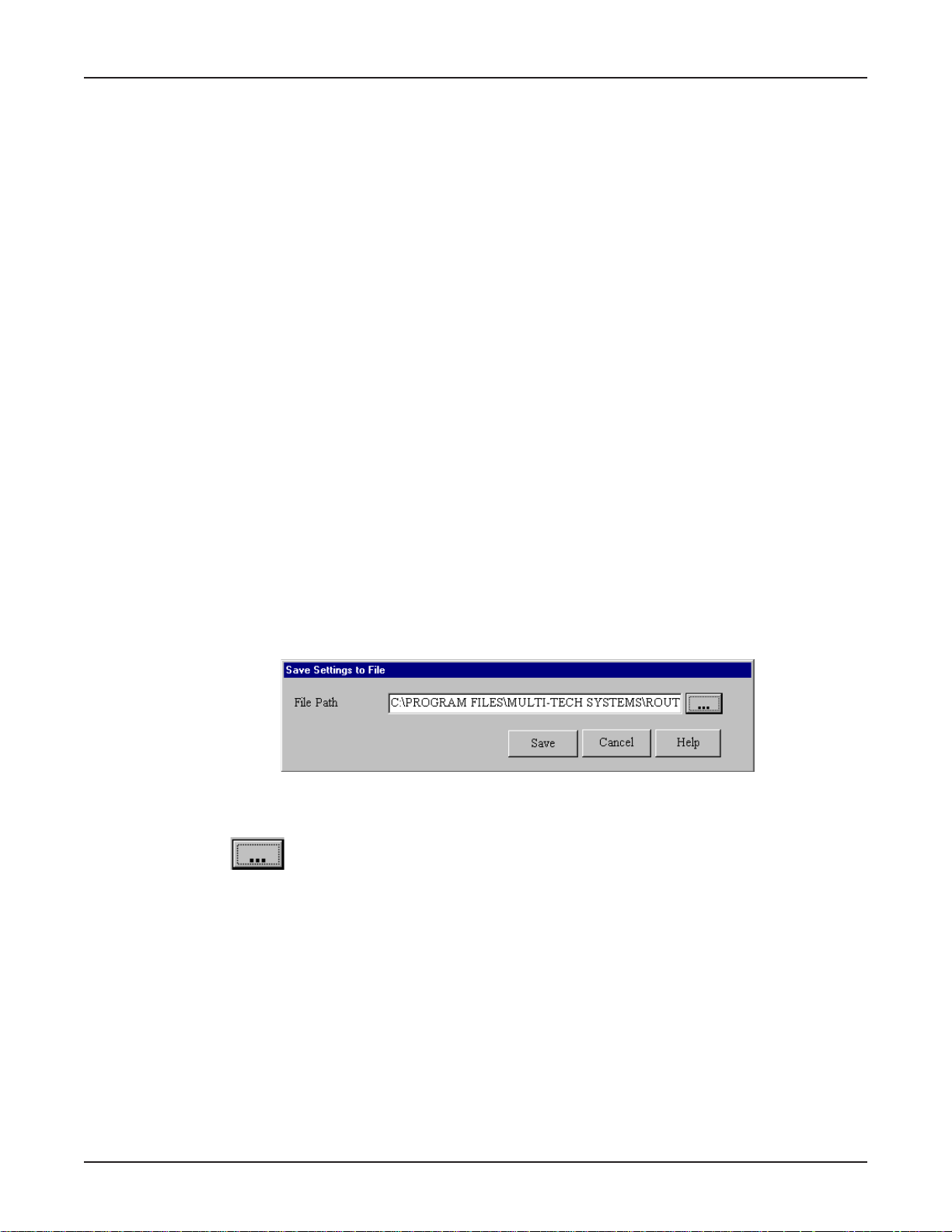
Device Name
The name of your network device displays. To change the name, simply enter a new name. If
you are connecting to an ISP via modem or ISDN TA, and your ISP requires you to enter a
computer name, you may use the device name that you’ve entered on this screen.
Domain Name
Enter your local network domain name.
Device Password
The RouteFinder manager does not come with a password enabled. If you choose to provide the
device with a password, you will be prompted to enter the password each time you want to
configure your network device. To enter a Password, type your password in the Device
Password box, then re-enter your password in the Password Verification box.
Note: If you choose to use a password, ensure you have selected something that will be easy to
remember or write it down and store it in a safe location. If you have completely forgotten your
password, contact the Multi-Tech T echnical Support group for assistance. Refer to Chapter 10 in
this User Guide for more information about our Technical Support services.
2. Click OK.
Save Settings to File
Chapter 5 - RouteFinder Manager
The Save Settings to File option allows you to save your settings to a file. This option provides a
method for backing up your system configuration so that it can be used in the event your settings
become accidently deleted. This option can also be used if you would like to have more than one set
of settings for your RouteFinder.
1. From the main Manager dialog box, click Save Settings to File.
2. The Save Settings to File dialog box displays.
To save your settings to a file:
1. In the File Path box, enter the full path to the file containing the settings you would like to use or
click then navigate to and select the file. You cansave a copy of the file to a different
location by changing the path.
2. Press OK to save the settings to the file name specified in step 1.
52
Page 53
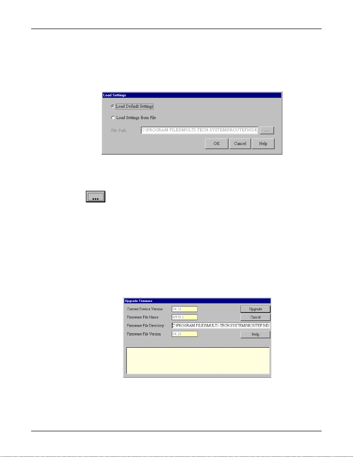
Load Settings
The Load Settings option allows you to load either the default settings of your network device or to
load settings previously saved to a file.
1. From the main Manager dialog box, select the Load Settings option.
2. The Load Settings dialog box displays.
3. To return the RouteFinder to factory default settings, select Load Default Setting.
4. To load a configuration from a file, select Load Settings From File.
5. In the File Path box, enter the full path to the file containing the settings you would like to use or
Chapter 5 - RouteFinder Manager
click then navigate to and select the file.
6. Click OK to load and apply the settings to the RouteFinder .
Upgrade Firmware
Warning: Upgrade the firmware of your RouteFinder RF102S only under the advice and direction of
the Multi-Tech T echnical Support Group. Improperly upgrading the RF102S may disable the device!
The Upgrade Firmware options allow you to upgrade your RF102S firmware. The Upgrade Firmware
option upgrades the firmware of your RF102S, not the RouteFinder Manager or Monitor software.
1. From the main Manager dialog box, click Upgrade Firmware.
2. The Upgrade Firmware dialog box displays.
T o Upgrade your firmware:
1. Download the latest firmware from the Multi-Tech System’s web site at www.multitech.com.
2. Copy the firmware to the directory containing the RouteFinder Manager program files. Refer to
the default Firmware File Directory box to determine the location of the files on your system.
53
Page 54
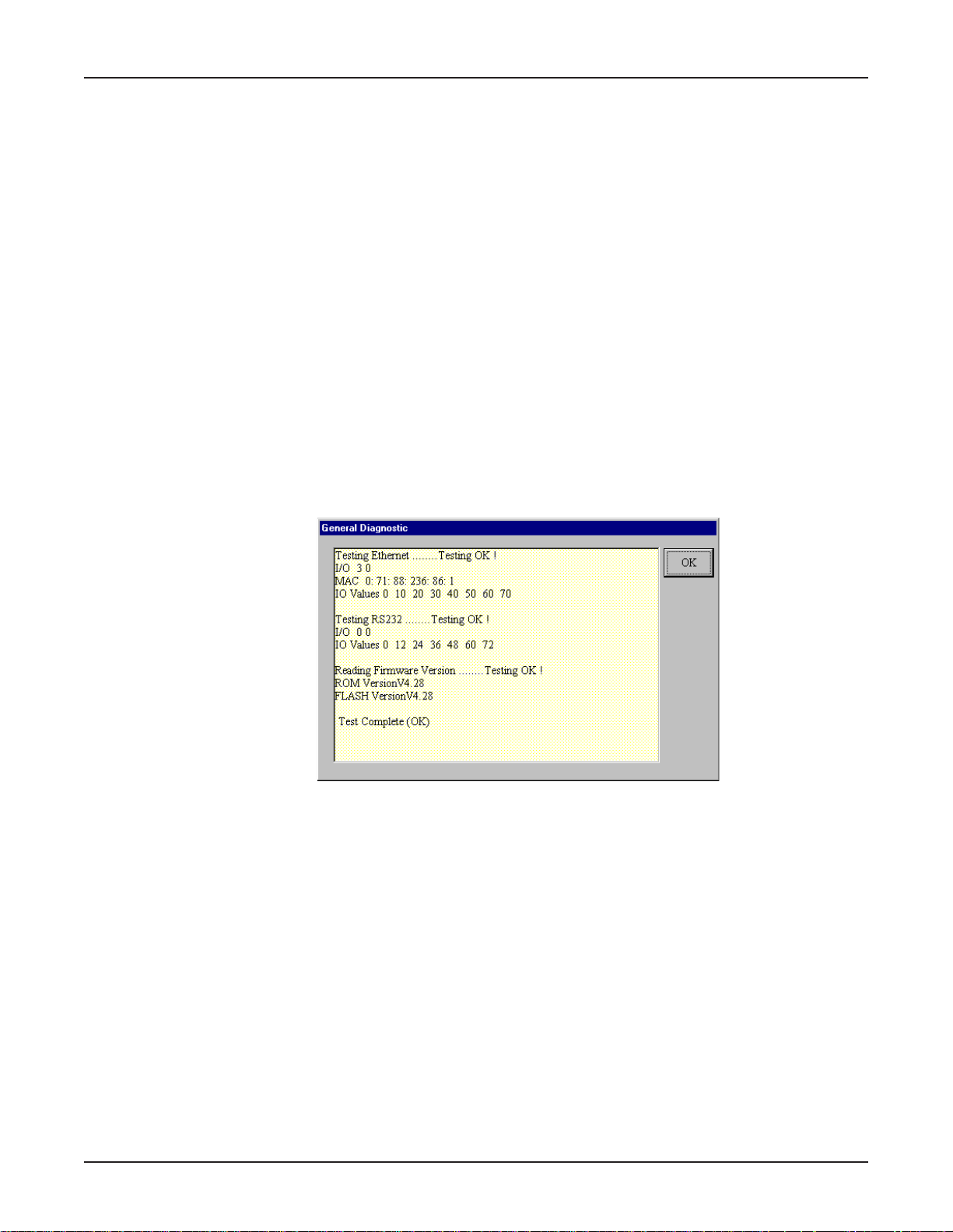
3. Enter the location of the new firmware file in the Firmware File Directory box. RouteFinder
Manager automatically detects the new firmware file name and displays it. The version number
of your firmware also displays.
4. Click Upgrade to upgrade your firmware.
5. A message appears stating the upgrade has started.
6. After several minutes, an informational dialog box displays indicating the upgrade was
successful.
7. Click OK.
8. From the main Manager dialog box, click Save and Exit.
9. Click Yes to restart the RouteFinder using the new firmware version.
General Diagnostic
The General Diagnostic option on the main RouteFinder Manager dialog box displays network device
information and allows you to determine if the RF102S is functioning properly.
1. From the main Manager dialog box, click General Diagnostic.
2. The General Diagnostic dialog box displays information about the RF102S.
Chapter 5 - RouteFinder Manager
3. Record the information if necessary and click OK to exit.
54
Page 55

Chapter 6 - RouteFinder Monitor
Page 56
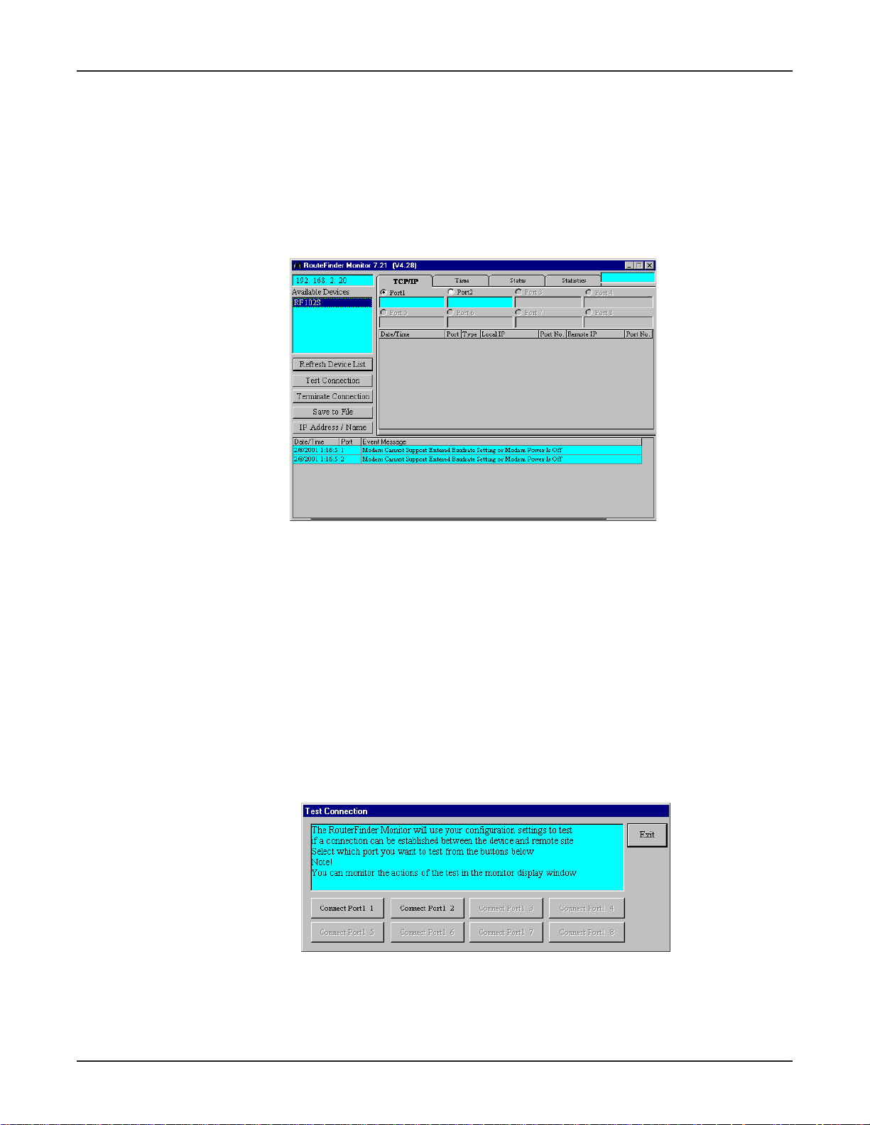
RouteFinder Monitor
RouteFinder Monitor is a utility that provides both monitoring and troubleshooting functions.
Running RouteFinder Monitor
1. Double-click the RouteFinder Monitor icon, or select Start | Programs | RouteFinder Manager |
RouteFinder Monitor.
2. The RouteFinder Monitor dialog box displays.
Chapter 6 - RouteFinder Monitor
Note: If you receive a message stating “Device is not found”, refer to the Troubleshooting
chapter in this User Guide.
Before using any of the RouteFinder Monitor options, you must select the device you are
attempting to configure from the Available Devices list. If you need to update the list, click
Refresh Device List.
Test Connection
The Test Connection option tests your connection settings and assist you in determining if problems
are due to the modem, the RouteFinder, or an incorrect setting. Test Connection uses the attached
modems to dial-up the remote server (ISP) and establish a connection.
1. From the main RouteMonitor dialog box, click T est Connection to begin testing.
2. The Test Connection dialog box displays.
3. Select Connect Port 1 to test the WAN connection, or Connect Port 2 to test the Async
connection.
4. The monitor display window displays the actions of the test.
6. Click Exit to close the Test Connection dialog box.
56
Page 57
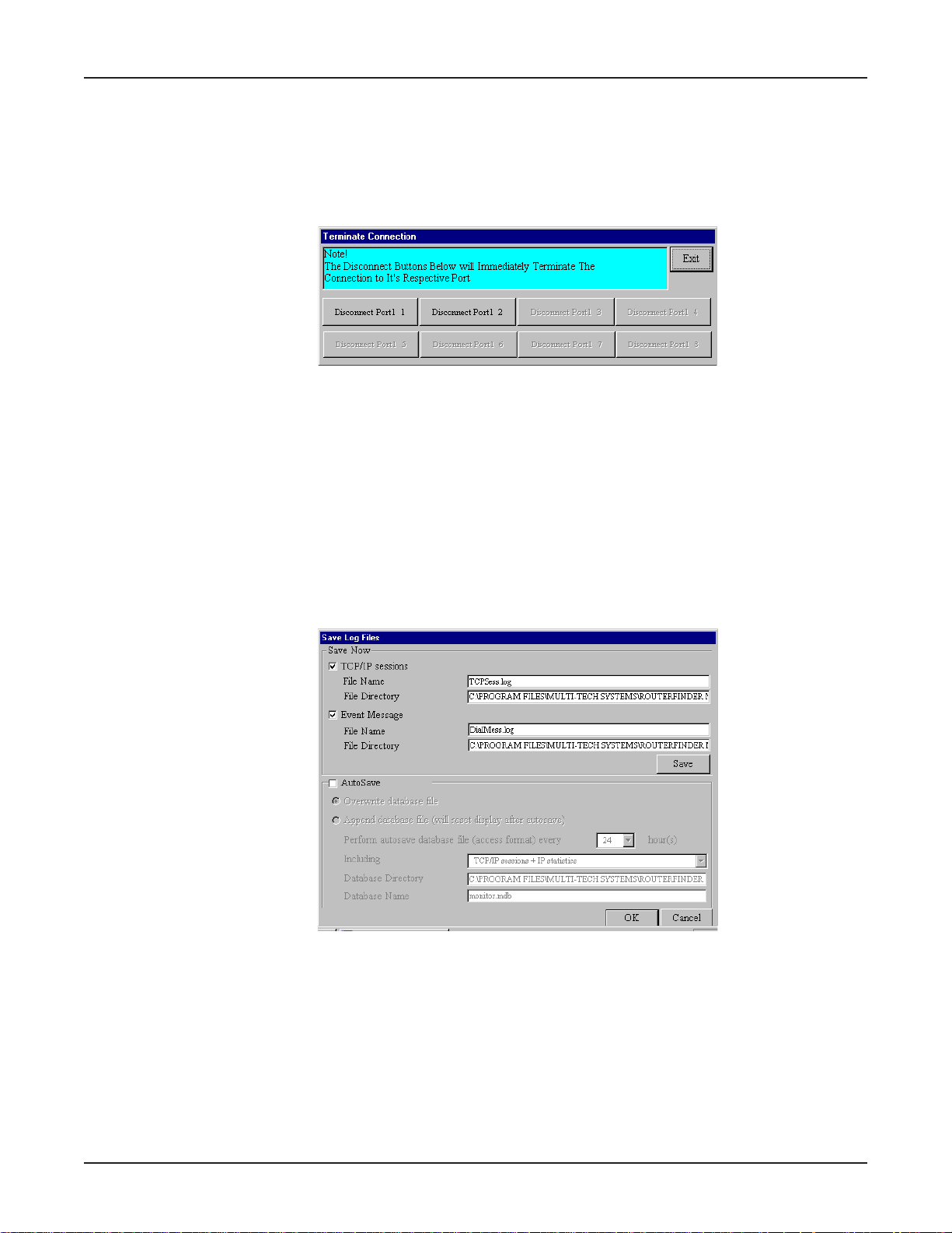
Terminate Connection
The Terminate Connection option is designed to allow the Network Administrator to terminate an
RF102S connection instantly .
1. From the main RouteFinder Monitor dialog box, select T erminate Connection.
2. The Terminate Connection dialog box displays.
3. Select Disconnect Port 1 or Disconnect Port 2.
4. Click T erminate Connection .
5. Click Exit to return to the RouteFinder Monitor dialog box.
Save to File
Chapter 6 - RouteFinder Monitor
Click Save to a File to save a monitoring session to a file. This feature can be used to create an
event log to send to our Technical Support group for evaluation.
1. From the main RouteFinder Monitor dialog box, select Save to File.
2. The Save Log Files dialog box displays.
Save Now
If you want to save the monitor display at any point in time, select the monitor you’d like to save
to a file (TCP/IP, Event Message, etc.). Select the File Name and File Directory to which you’d
like to save the file and click Save.
57
Page 58
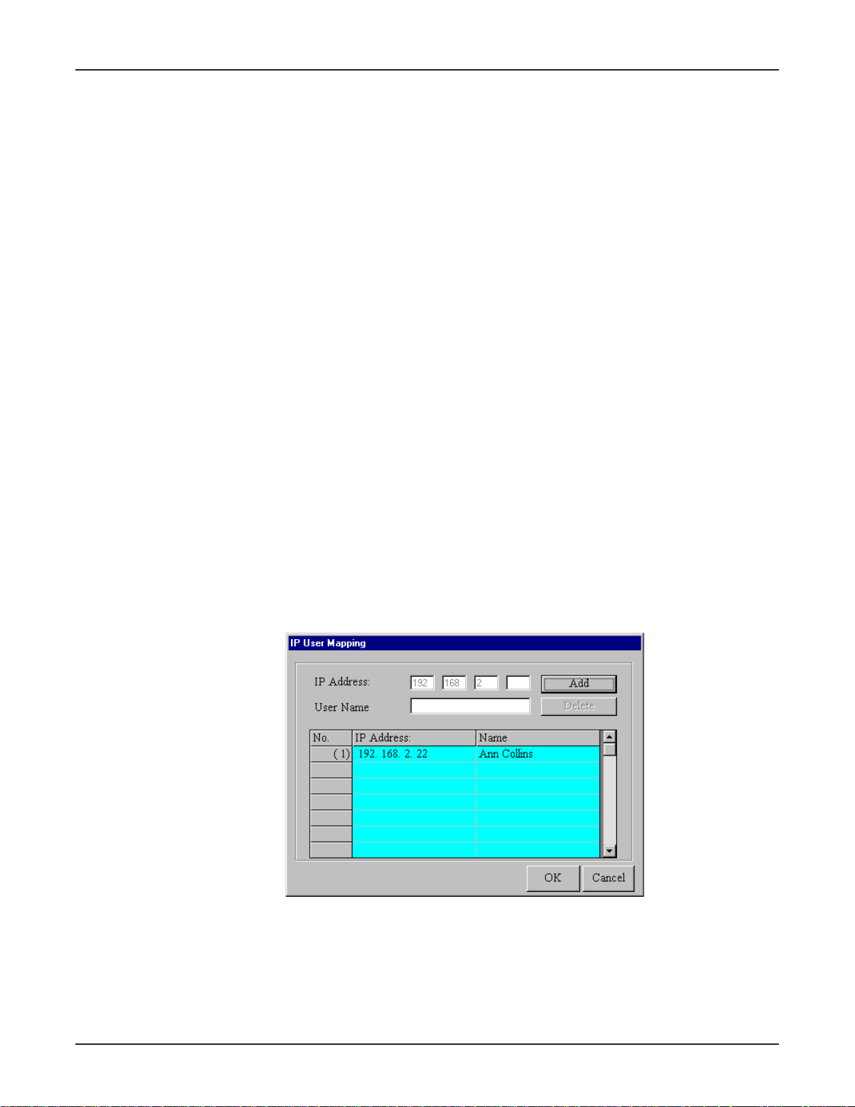
Autosave
If you wish to automatically save the information displayed on the monitor to a database file,
enable the AutoSave function. Options for this function include:
Overwrite database file
This option saves the information collected by the monitor to a database file based on the time
interval that you specify , overwriting the last saved database file.
Append Database file
This option saves the information collected by the monitor to a database file based on the time
interval that you specify , updating and appending to the file.
Note: The Append Database file option will reset the monitor and clear the screens after the
autosave has appended the information to the file.
Warning: The database size limit is equal to the amount of available disk space. Use this option
with caution!
3. Click OK when complete.
IP Address/Name
The IP Address/Name function allows you to associate a name with a particular IP address and name
on your network. This information will appear in the relevant monitor displays. The IP Address/Name
option is used to assist the Network Administrator in determining which users are transmitting and
receiving data without having to remember their specific IP addresses.
Chapter 6 - RouteFinder Monitor
Each computer listed must have a fixed IP address for your network. You may configure a fixed IP
address on the individual computer or use the RF102S’s DHCP server IP reservation system (refer to
the LAN DHCP section of RouteFinder Manager chapter of this User Guide).
1. From the main RouteFinder Monitor dialog box, click IP Address/Name.
2. The IP User Mapping dialog box displays.
3. Enter each computer’s IP Address and associated User Name.
4. Click Add after each IP address and name have been added to the list.
5. When all addresses have been added, click OK.
58
Page 59
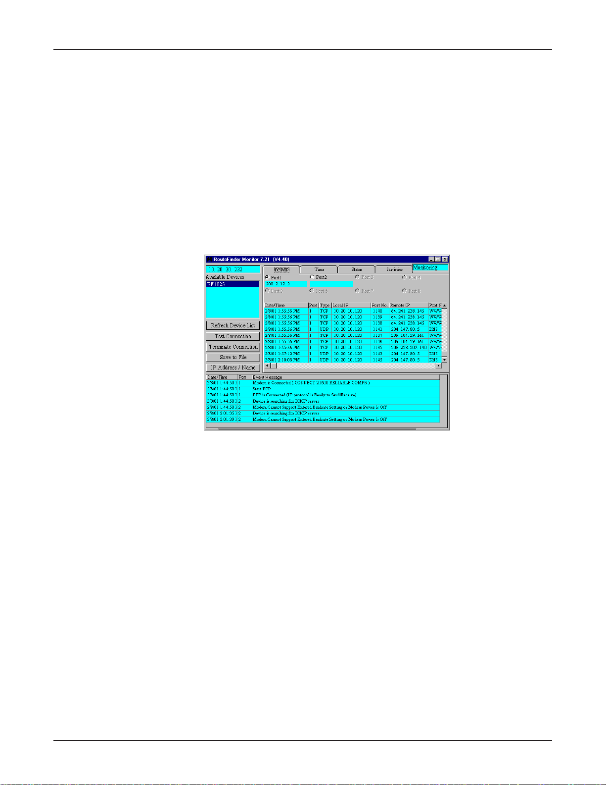
Event Messages
Event Messages are displayed in the lower half of the RouteFinder Monitor display. Event
Messages provide information about the communication occurring between your network device,
ISDN TA/modem and the remote server (ISP).
To assist you in troubleshooting, you may point and click on any event message to bring up a help
screen.
TCP/IP Tab
The TCP/IP tab displays all TCP/IP requests made by your network device. You may select to view
TCP/IP sessions for the WAN Ethernet or the Async Port.
1. The TCP/IP tab is the default tab displayed in the RouteFinder Monitor dialog box. If it is not
displayed, click the TCP/IP tab.
Chapter 6 - RouteFinder Monitor
Note: The TCP/IP sessions displays the history of the TCP/IP session through the selected port.
The TCP/IP information presented does not represent the current status of the TCP/IP session.
The TCP/IP tab displays the following information:
Date/Time: Indicates the date the request was made.
Port: Indicates the port you are viewing.
Type: Displays the type of request being made.
Local IP: Indicates which IP address you have requested information from.
Remote IP: Indicates which IP address was requested.
Port Number: Indicates which TCP/IP port was requested.
2. To exit RouteFinder Monitor, close the window.
59
Page 60
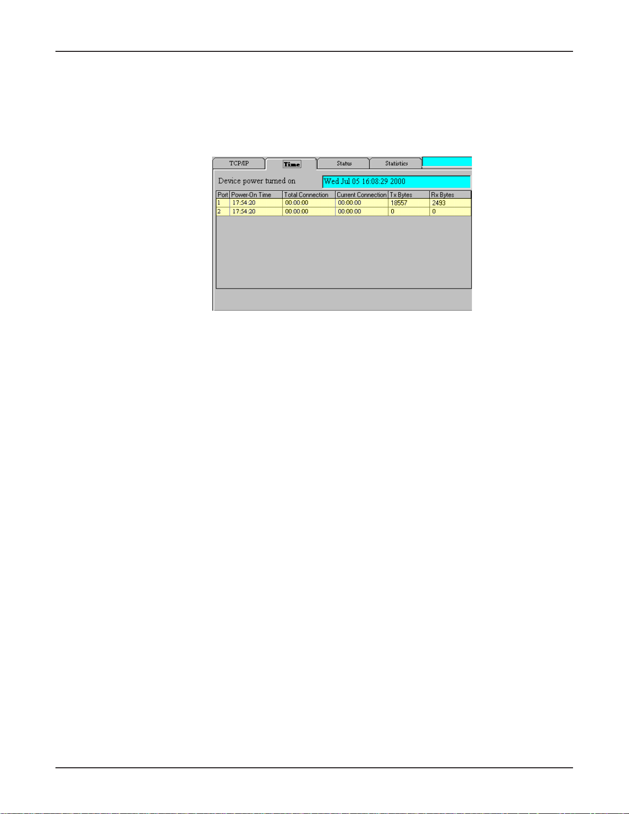
Time Tab
The Time Tab provides information about the amount of time the device has been powered on, the
total connection time, the current connection time and the amount of data transferred and received.
1. From the main RouteFinder Monitor dialog box, click the Time tab.
2. The Time tab displays information for each port.
Chapter 6 - RouteFinder Monitor
Device Power Turned On
Displays the time/date that power was turned on to your RF102S .
Power-On-Time
Displays the total time that has elapsed since power was turned on to your RF102S .
T otal Connection Time
Displays the total connection time for each port that has been logged on since power was turned
on to your RF102S.
Current Connection
Displays the time that has elapsed since the current connection was established for the port.
TX Bytes
Displays the total number of bytes transmitted for each port since power was last turned on to
your RF102S.
RX Bytes
Displays the total number of bytes received for each port since power was last turned on to your
your RF102S was last powered on.
3. To exit RouteFinder Monitor, close the window.
60
Page 61
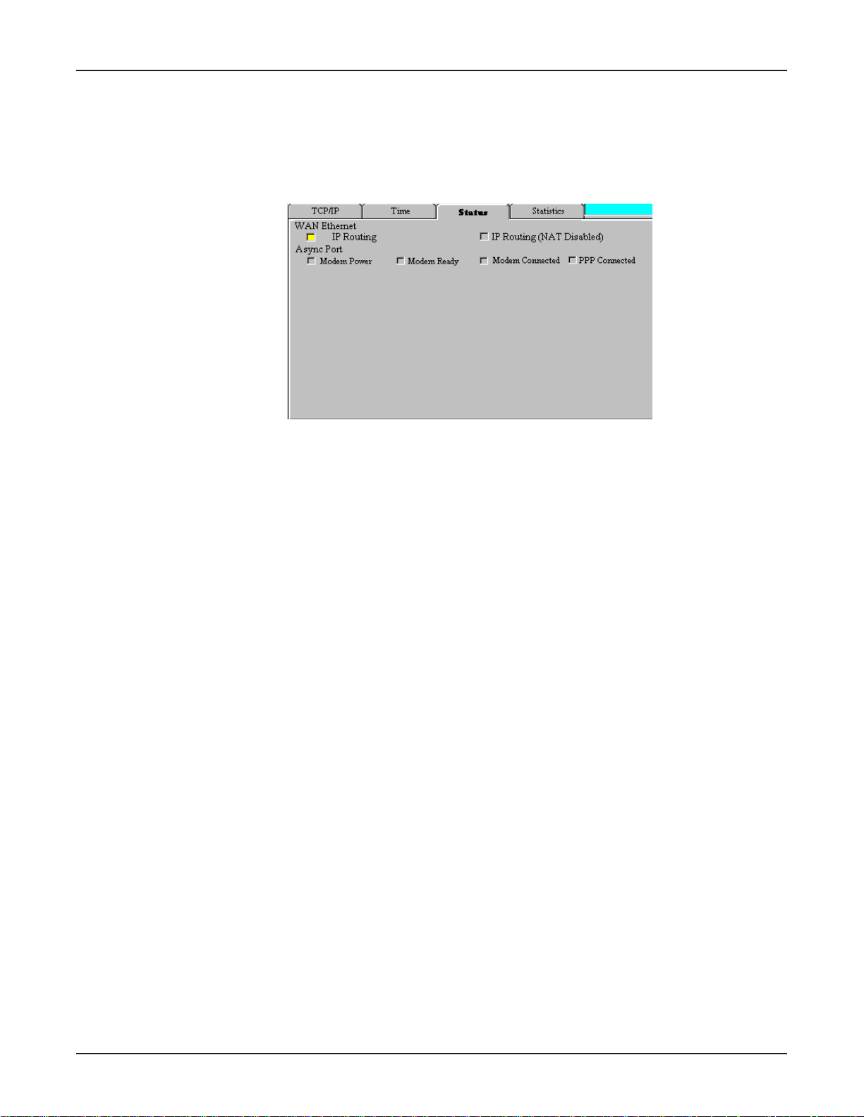
Status Tab
The Status tab provides information about the status of the Serial ports.
1. From the RouteFinder Monitor dialog box, click the Status tab.
2. The Status tab information displays:
WAN Ethernet
This indicator light shows that either the IP Routing or the Remote Access function is in use.
Chapter 6 - RouteFinder Monitor
Async Port
Modem Power:
The indicator light is lit when the modem power is turned on.
Modem Ready
The Network Device sends a pre-initialization and initialization command to the modem or ISDN
T A. If this communication is successful, the indicator light will be lit, indicating your modem is
ready to make a connection.
Modem Connected
If the Network Device has detected that your modem has successfully dialed up a connection to
a remote site, the indicator light will be lit.
PPP Connected
After a connection is established, if the RouteFinder has detected that the PPP connection is
successful, this indicator light will be lit.
3. To exit RouteFinder Monitor, close the window.
61
Page 62
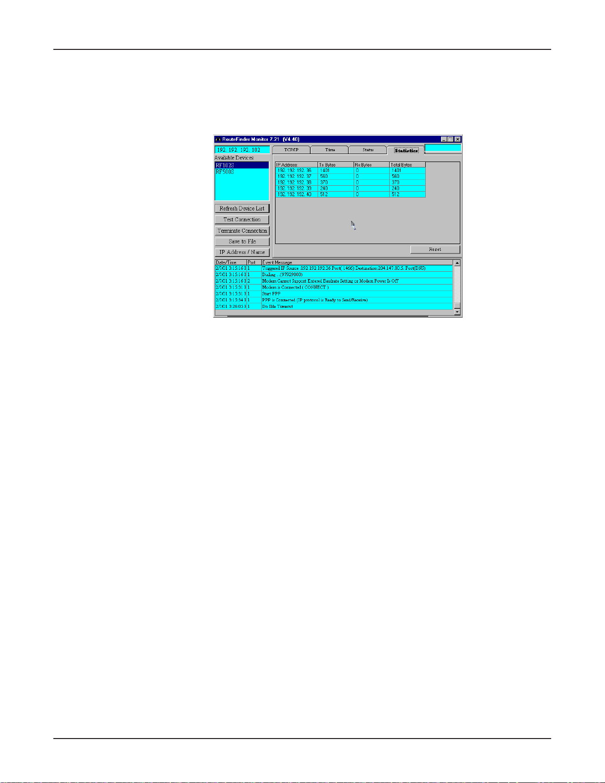
Statistics Tab
The Statistics tab indicates, by port, how many bytes of data have come in and out through the
RouteFinder..
1. From the RouteFinder Monitor dialog box, click the Statistics tab.
Chapter 6 - RouteFinder Monitor
2. You can view the following information:
IP Address
The IP address of the network device.
Name
The Name as entered in the IP/Address name option of the RouteFinder Monitor dialog box.
Tx Bytes
Displays the number of bytes transmitted from the computer with this IP address.
Rx Bytes
Displays the number of bytes received from the computer with this IP address.
T otal Bytes
Displays the total number of bytes received and transmitted from the computer with this IP
address.
3. Click Reset to set the IP statistics to zero.
4. To exit RouteFinder Monitor, close the window.
62
Page 63

Chapter 7 - LAN Client Settings
Page 64

LAN Client Settings
In order for a computer to access the Internet, the TCP/IP protocol must be installed on the computer.
Computers on your local LAN as well as computers dialing in to your network may use dynamic or
static IP addresses. Dynamic IP addresses may be automatically assigned by the DHCP function of
the RF102S or another DHCP server . Static IP addresses can either be reserved from the DHCP
server or manually configured on the individual workstation.
To install or verify that TCP/IP is installed on your workstations, click Start | Settings | Control
Panel, click Network, then view the Protocol information. If the TCP/IP protocol is not installed on
your workstations, you must add it. Refer to the Adding TCP/IP section in the following pages, or
your Windows documentation for assistance in adding the protocol.
The default setting in Windows is to have IP information (IP Address, DNS Server IP address and
Gateway IP address) automatically assigned by a DHCP server such as the one built-in to your
RouteFinder.
If you’d like to manually configure the IP addresses on your workstation, you will need to provide an
IP address and subnet mask (the local LAN IP address and subnet you want to assign to the
individual computer), a Gateway address (the local LAN IP address of your RouteFinder) and a DNS
Server address (the DNS IP address provided by your ISP).
Warning: As a general rule, you should have only one DHCP server working on your network. If you
decide to use a DHCP server other than that provided with your RouteFinder , you should use
RouteFinder Manager to disable the DHCP LAN Server function. You should also set your
RouteFinder’s IP address as the gateway to the other DHCP server .
Chapter 7 - LAN Client Settings
Setting up Remote Access Clients
Dial-in connections to Windows NT, Novell and Unix servers require slightly different configurations.
This section discusses the settings necessary to connect a Windows 95/98/NT/2000 workstation to
these various servers.
Note: the Windows 2000 operating system has a Network Connection Wizard for making new
connections, shown on the last page of this section.
The basic process consists of installing a dial-up adapter and a network protocol. Then, depending
on the server to which you are connecting, you will likely need to install client software and specify
the particular services you want to use.
Accessing a Windows NT Server
Windows NT Server combines the best aspects of an application server, a file and printer server, a
communications server, and a W eb server, and its interoperability and management features make it
an excellent network operating system (NOS) for organizations, whether they have mixed computing
environments or operate entirely on Windows NT Server . Perform the following procedures when you
need to connect your PC workstation to a remote Windows NT Server .
64
Page 65
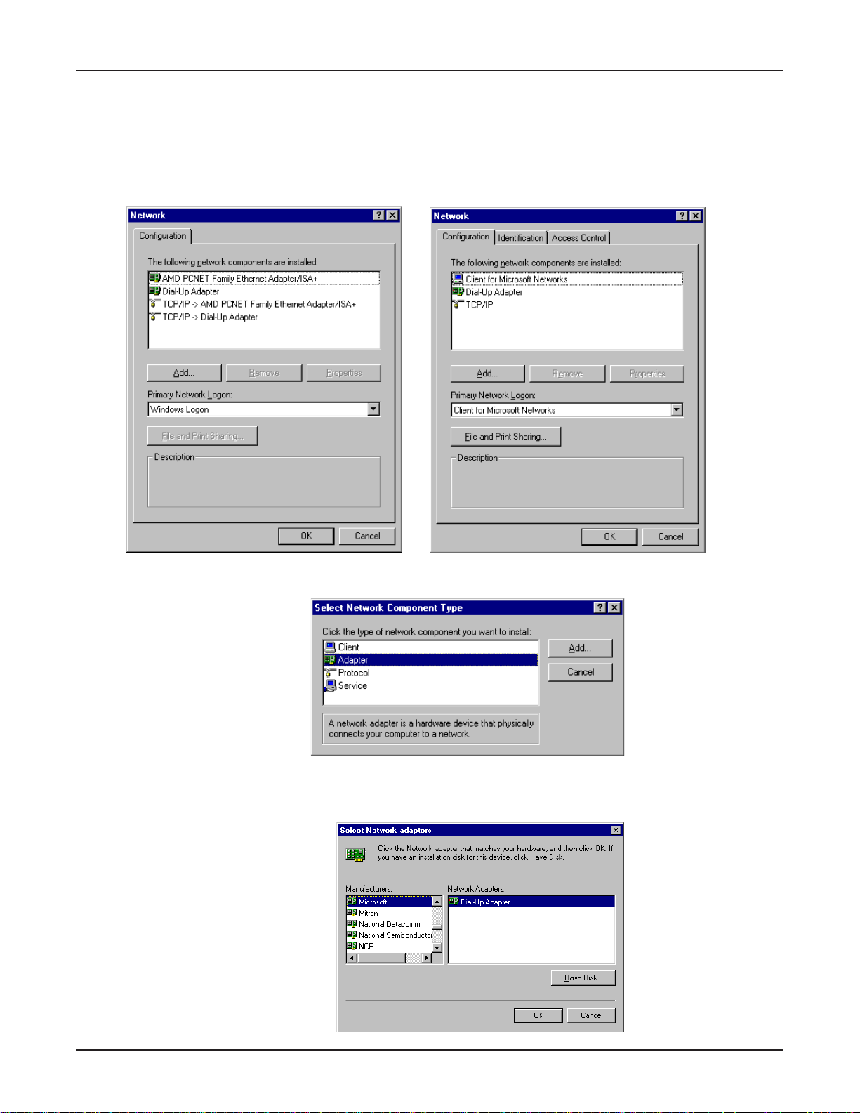
Adding the dial-up adapter (NT Server Connection):
Windows 95/98:
1. Click Start | Settings | Control Panel.
2. Double-click the Network icon to open the Network dialog box.
Win95 Win98
Chapter 7 - LAN Client Settings
3. Click Add; the Select Network Component T ype dialog box opens.
4. Select Adapter, then click Add. The Select Network adapters dialog box opens.
Win95/98
65
Page 66
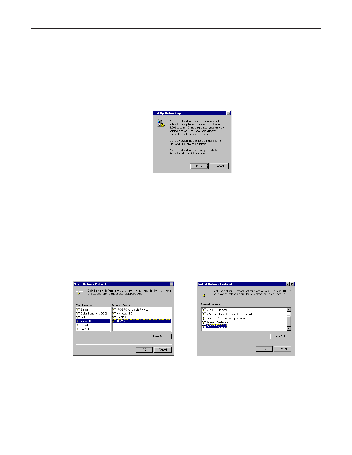
Chapter 7 - LAN Client Settings
5. In the Manufacturers option box, select Microsoft. In the Network Adapters option box select
Dial-up adapter.
6. Click OK (twice) to return to, and then close, the Network dialog box.
Windows NT:
Dial-up Networking adds PPP and SLIP protocol support, enabling your workstation to gain access to
a remote computer or network, even if your computer is not on a network.
1. Double-click My Computer, then double-click Dial-Up Networking. The following screen is
displayed:
2. Click Install, then follow the onscreen instructions to configure your connection.
Adding TCP/IP (NT Server Connection):
Windows 95/98/NT:
1. In the Network dialog box, Configuration tab, click Add.
2. Select Protocol and click Add.
3. The Select Network Protocol dialog box is displayed. In the Manufacturers option box [Win95
only], select Microsoft. In the Network Protocols option box, select TCP/IP [Win95/98] or TCP/
IP Protocol [WinNT only].
[Note: Windows NT workstation has no Manufacturers option box.]
Win95/98 WinNT
4. Click OK twice to return to and close the Network dialog box.
66
Page 67
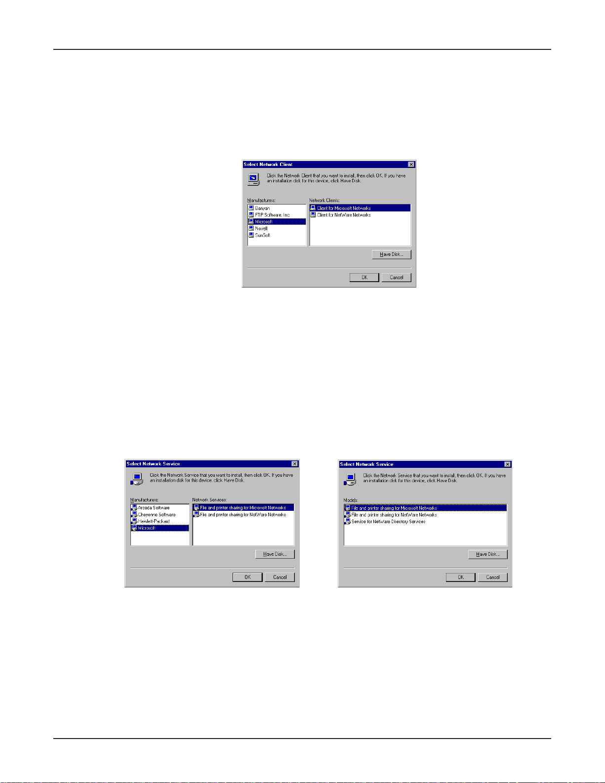
Chapter 7 - LAN Client Settings
Adding Client for Microsoft Networks (NT Server Connection):
Windows 95/98:
1. In the Network dialog box, Configuration tab, click Add.
2. Select Network Client and click Add.
3. The Select Network Client dialog box displays. In the Manufacturer’s option box, select
Microsoft. In the Network Clients option box, select Client for Microsoft Networks.
4. Click OK to add this Client and return to the Network dialog box.
Adding File and Print Sharing for Microsoft Networks (NT Server Connection):
Windows 95/98:
1. In the Network dialog box, Configuration tab, click Add.
2. Select Services and click Add.
3. The Select Network Service dialog box displays. In the Manufacturers option box, select
Microsoft. Select File and Printer sharing for Microsoft Networks.
[Note: Windows 98 has no Manufacturers option box.]
Win95 Win98
4. Click OK twice to return to and close the Network dialog box.
67
Page 68
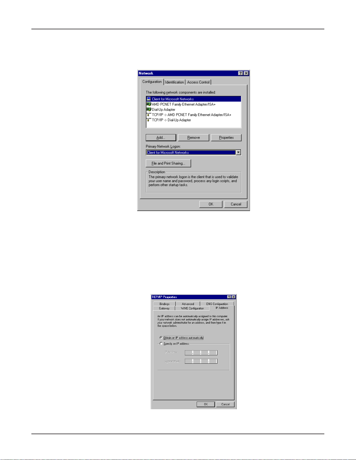
Chapter 7 - LAN Client Settings
Set Your Primary Network Logon (NT Server Connection):
Windows 95/98:
1. In the Primary Network Logon option box on the Configuration tab of the Network dialog box,
select (the previously installed) Client for Microsoft Networks.
2. Click OK to close the Network dialog box.
Set up Properties of Components (NT Server Connection):
Dial-up Adapter:
Windows 95/98:
1. In the Network dialog box, Configuration tab, select the TCP/IP - Dial-up adapter.
2. Click Properties. The TCP/IP Properties dialog box opens with the IP Address tab
selected.
3. Ensure that Obtain an IP Address Automatically is selected. (It’ s the default.)
4. Click OK to close the TCP/IP Properties dialog box.
68
Page 69
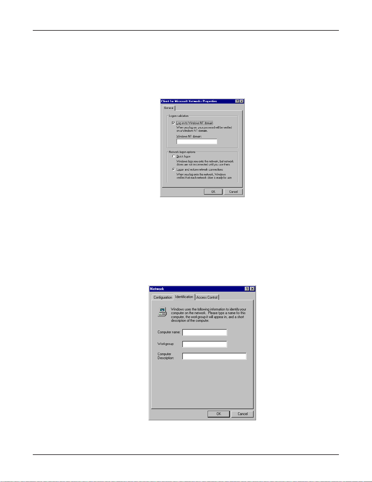
Chapter 7 - LAN Client Settings
Network Client:
Windows 95/98:
1. In the Network dialog box, Configuration tab, select Client for Microsoft Networks.
2. Click Properties. The Client for Microsoft Networks Properties dialog box opens.
3. On the General tab, select (check) Log on to Windows NT domain.
4. Enter the name of your Windows NT domain, as provided by your Network Administrator the
Windows NT domain box.
5. Click OK to return to the Network dialog box.
Identification:
Windows 95/98:
1. In the Network dialog box, select the Identification tab.
2. In the Workgroup box, enter the name of your NT domain or the name of your workgroup as
provided by your Network Administrator.
3. Enter a name and description for your computer.
4. Click OK.
69
Page 70
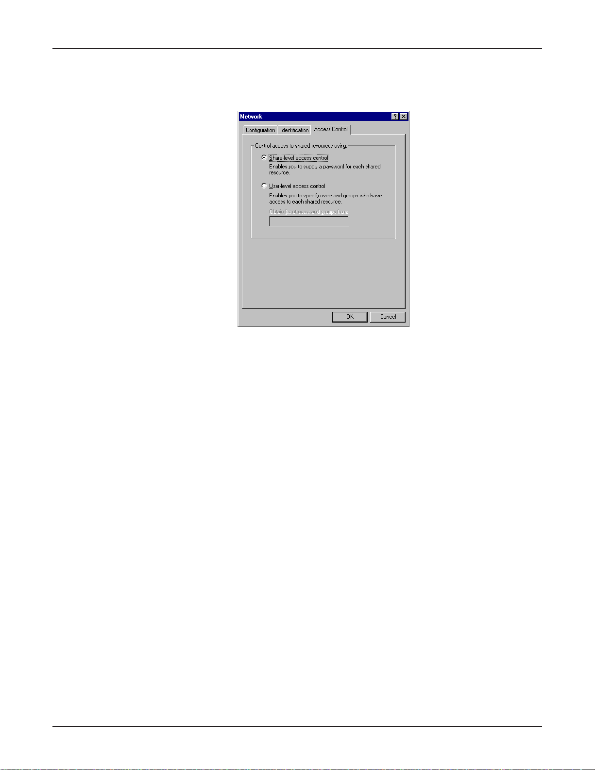
Chapter 7 - LAN Client Settings
Access:
Windows 95/98:
1. In the Network dialog box, click the Access Control tab.
2. In the Control Access to Shared resources using group, select Share-Level access control.
3. Click OK (twice) to return to, and then close, the Network dialog box.
Note: You must restart your system for the new settings to take effect.
Once your machine has restarted, you may continue the configuration process.
Make Your New Connection (NT Server Connection):
Windows 95/98:
1. Double-click My Computer.
2. Double-click the Dial-Up Networking folder.
3. Double-click Make New Connection (or Add New Connection, Win98).
4. Follow the on-screen instructions to configure your connection.
Windows NT:
1. Double-click My Computer.
2. Double-click Dial-Up Networking.
3. When the Dial-Up Networking dialog box opens, click Install.
4. Follow the on-screen instructions to configure your connection.
Set Dial-up type (NT Server Connection):
Windows 95/98:
1. Right-click the newly created connection icon, then click Properties; the My Connection dialog
box opens.
2. On the General tab, click Server Type; the Server Types dialog box opens. Select PPP:
Windows 95, Windows NT 3.5, Internet.
3. Click (to check or enable) only the following items: Log on to network, Enable software
compression, and TCP/IP. Do not disturb any other items that are already checked.
70
Page 71
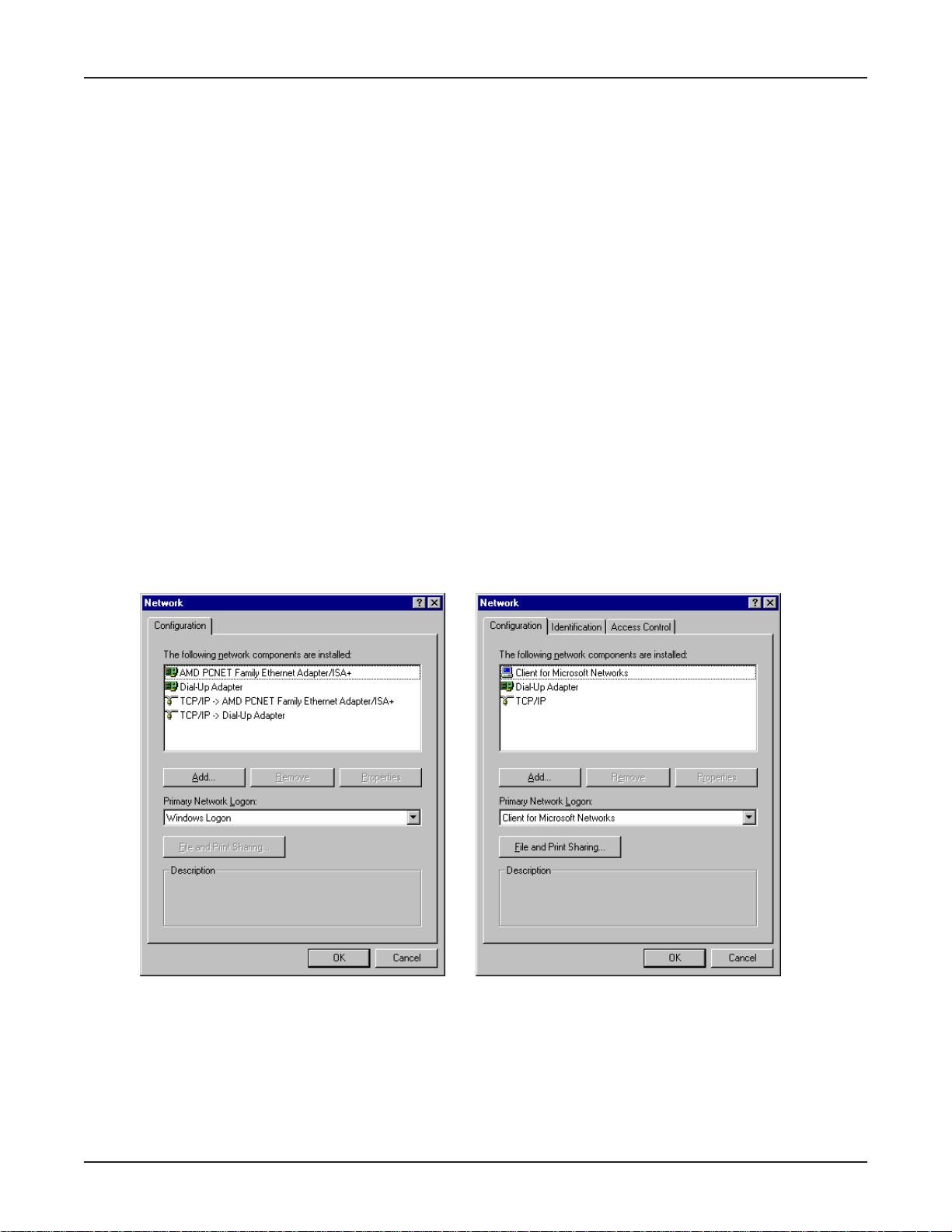
Chapter 7 - LAN Client Settings
Dial in to your network (NT Server Connection):
Windows 95/98:
1. You are ready to dial in to your network.
2. Double-click the new connection icon. The Connect To dialog box opens.
3. Enter the user name (if necessary) and password configured for you on the RF102S.
Note: If your particular situation permits, select Save password.
4. Click Connect.
5. After connecting to the RF102S, you can access the same services and resources as if you were
connected to the network locally .
Accessing a Novell Server
Novell NetWare products are used on up to 70 percent of PC-based local area networks (LANs).
Perform the following procedures when you need to connect your PC workstation to a remote Novell
Server.
Adding the dial-up adapter (Novell Server Connection):
Windows 95/98:
1. Click Start | Settings | Control Panel.
2. Double-click the Network icon to open the Network dialog box.
Win95 Win98
3. Click Add. The Select Network Component Type dialog box opens.
71
Page 72
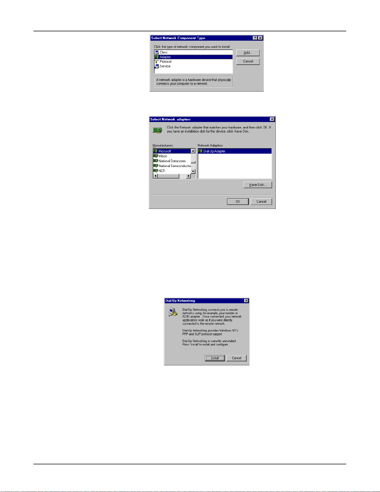
Chapter 7 - LAN Client Settings
4. Select Adapter, then click Add. The Select Network adapters dialog box opens.
Win95/98
5. In the Manufacturers option box, select Microsoft. In the Network Adapters option box select
Dial-up adapter.
6. Click OK twice to return to and close the Network dialog box.
Windows NT:
Dial-up Networking adds PPP and SLIP protocol support, enabling your workstation to gain access to
a remote computer or network, even if your computer is not on a network.
1. Double-click My Computer, then double-click Dial-Up Networking. The following window
displays:
2. Click Install, then follow the on-screen instructions to configure your connection.
72
Page 73
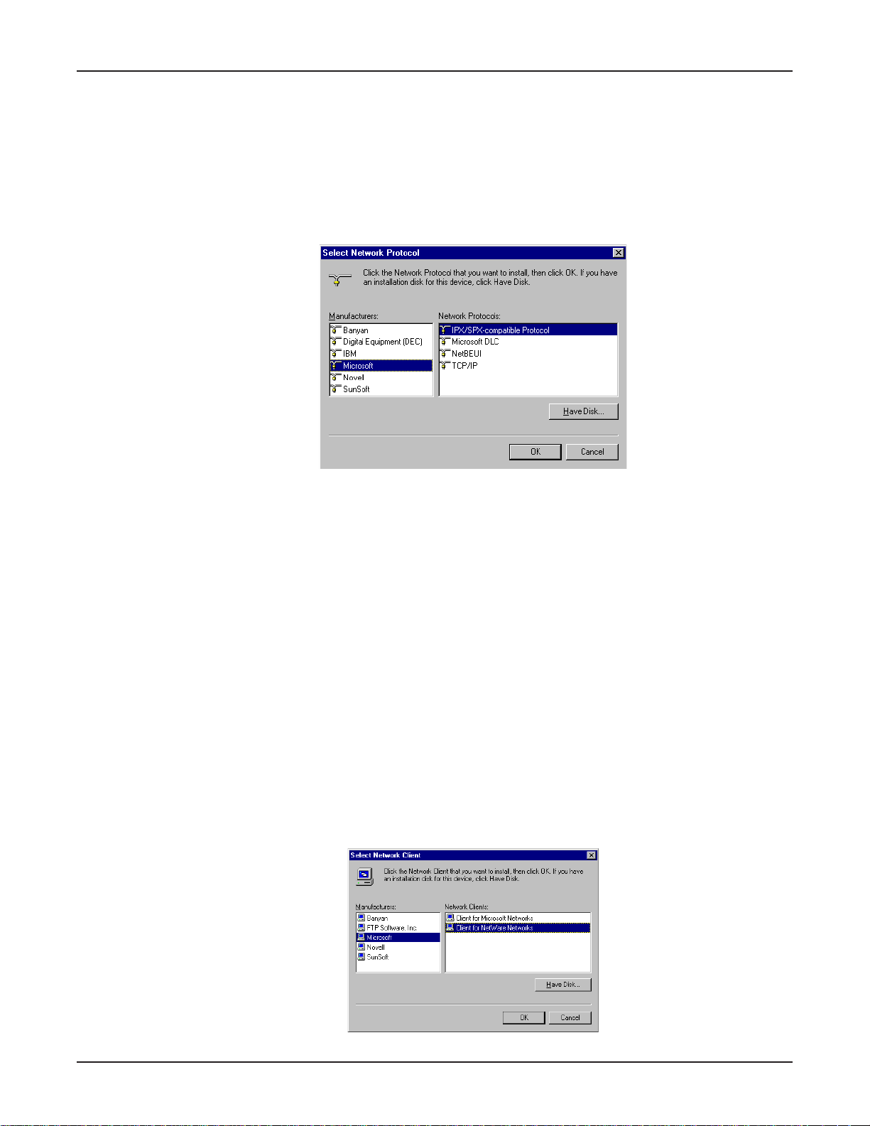
Chapter 7 - LAN Client Settings
Adding IPX/SPX (Novell Server Connection):
Windows 95/98:
1. In the Network dialog box, Configuration tab, click Add. The Select Network Component
Type dialog box opens.
2. Select Protocol and click Add. The Select Network Protocol dialog box opens.
3. In the Manufacturers option box, select Microsoft. In the Network Protocols option box, select
IPX/SPX-compatible Protocol.
4. Click OK (twice) to return to, and then close, the Network dialog box.
Windows NT:
Note: NWLink IPX/SPX Compatible Transport is probably already installed, along with NWLink
NetBIOS and TCP/IP Protocol; however, if NWLink IPX/SPX Compatible Transport does not
appear on the Protocols tab of the Network dialog box, perform the following steps:
1. In the Network dialog box, Protocol tab, click Add. The Select Network Protocol dialog box
opens.
2. Select NWLink IPX/SPX Compatible Transport , then click OK.
3. Click Close to close the Network dialog box and return to the Desktop.
Adding Client for NetWare Networks (Novell Server Connection):
Windows 95/98:
1. In the Network dialog box, Configuration tab, click Add.
2. Select Network Client and click Add.
3. The Select Network Client dialog box displays. In the Manufacturer’s option box, select
Microsoft. In the Network Clients option box, select Client for NetWare Networks.
4. Click OK to add this Client and return to the Network dialog box.
73
Page 74
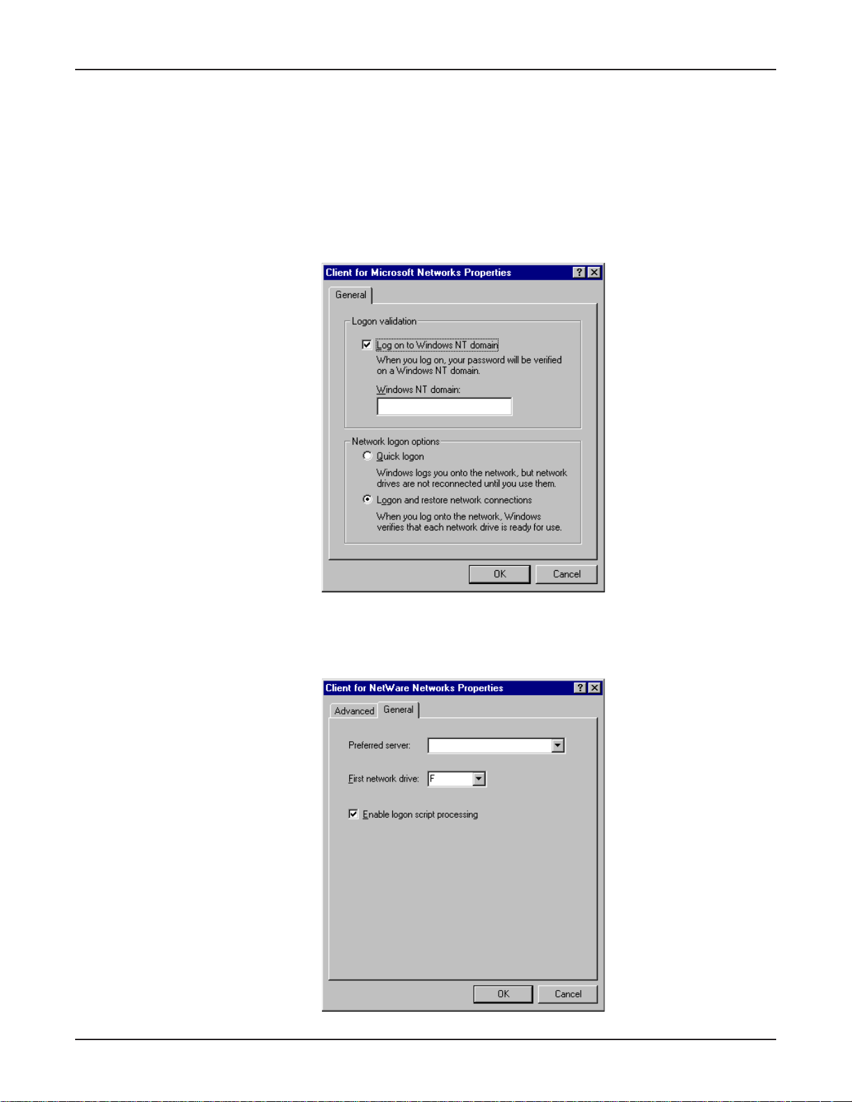
Chapter 7 - LAN Client Settings
Set Up Properties of Components (Novell Server Connection):
Network Client:
Windows 95/98:
1. In the Network dialog box, Configuration tab, select Client for Microsoft Networks.
2. Click Properties. The Client for Microsoft Networks Properties dialog box opens.
3. On the General tab, select the Log on to Windows NT domain check box.
4. Enter the name of your Windows NT domain in the Windows NT domain box, as provided by
your Network Administrator.
5. Click OK to return to the Network dialog box.
6. In the Network dialog box, Configuration tab, select Client for NetWare Networks.
7. Click Properties.
74
Page 75
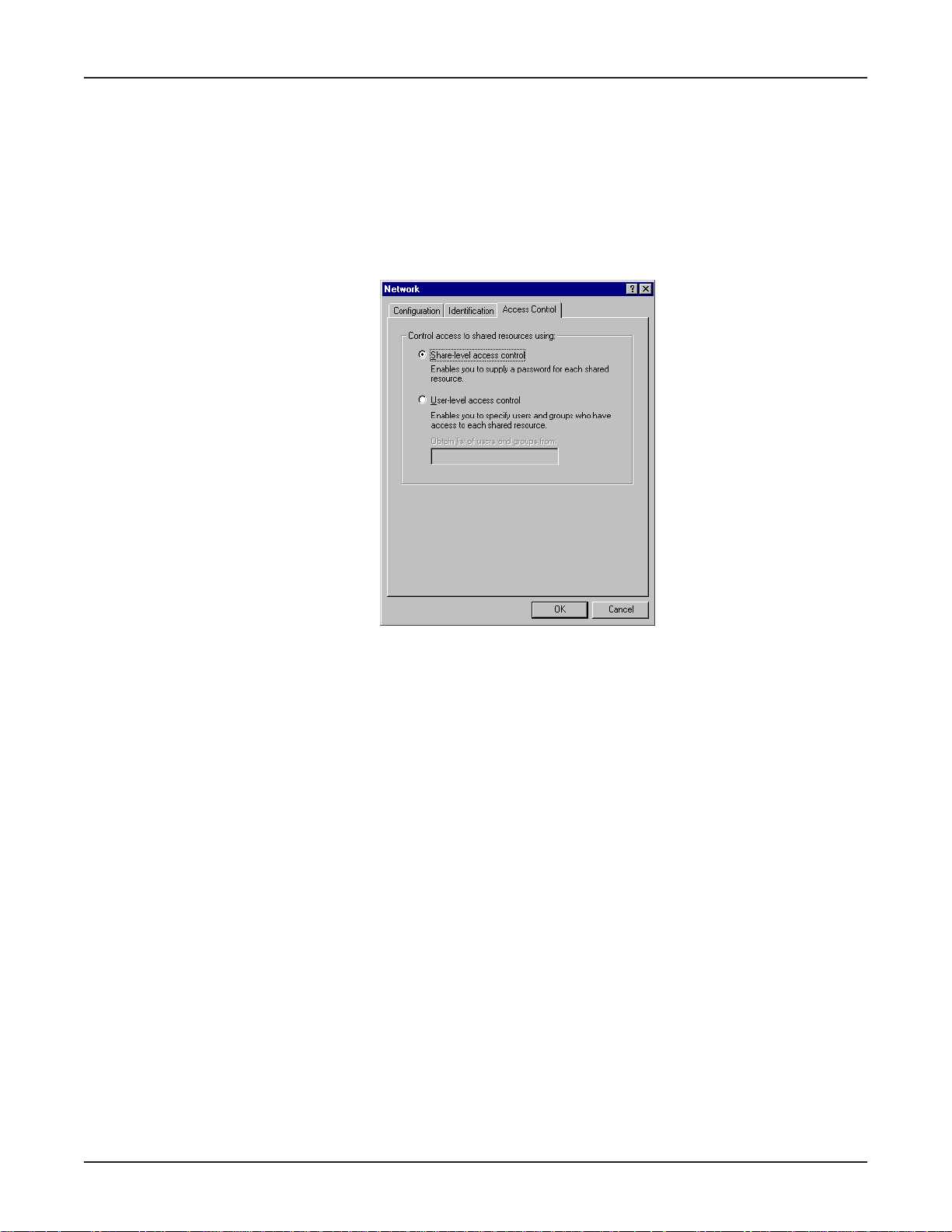
Chapter 7 - LAN Client Settings
8. On the General tab, in the Preferred server field, enter the name of your Novell Server Domain. If
necessary , select the First Network Drive, then ensure that Enable logon script processing is
checked (enabled). (It’s the default.)
9. Click OK to return to the Network dialog box.
Set Your Primary Network Logon:
Windows 95/98:
1. In the Network dialog box, Configuration tab, select Client for NetWare Networks
as the Primary Network Logon.
2. Click OK. You are returned to the Desktop.
Set Your Access Control (Novell Server Connection):
Windows 95/98:
1. In the Network dialog box, select the Access Control tab.
2. In the Control Access to shared resources using option box, select Share-Level Access
Control.
Note: You must restart your system for the new settings to take effect.
Make Your New Connection (Novell Server Connection):
Windows 95/98:
1. Double-click My Computer.
2. Double-click the Dial-Up Networking folder.
3. Double-click Make New Connection (or Add New Connection, Win98).
4. Follow the on-screen instructions to configure your connection.
Windows NT:
1. Double-click My Computer.
2. Double-click Dial-Up Networking.
3. When the Dial-Up Networking dialog box opens, click Install.
4. Follow the on-screen instructions to configure your connection.
75
Page 76

Chapter 7 - LAN Client Settings
Set Dial-up type (Novell Server Connection):
Windows 95/98:
1. Right-click the newly created connection icon, then click Properties. The My Connection
dialog box opens.
2. On the General tab, click Server Type. The Server Types dialog box opens. Select PPP:
Windows 95, Windows NT 3.5, Internet.
3. Select only the following items: Log on to network, Enable software compression, and TCP/
IP. Do not disturb any other items that are already checked.
Dial in to your network (Novell Server Connection):
Windows 95/98:
1. You are ready to dial in to your network.
2. Double-click the new connection icon. The Connect To dialog box opens.
3. Enter the user name (if necessary) and password configured for you on the RF102S.
Note: If your particular situation permits, select Save password.
4. Click Connect.
5. After connecting to the RF102S, you can access the same services and resources as if you were
connected to the network locally.
Accessing a Windows NT Server and a Novell NetWare Server
Note: Before configuring your remote site, ensure TCP/IP has been installed on your NT Server.
Perform the following procedures if your PC workstation needs to access both a Windows NT Server
and a Novel NetWare Server.
Adding the dial-up adapter (Novell/NT Server Connection):
Windows 95/98/NT:
1. Click Start | Settings | Control Panel.
2. Double-click the Network icon to open the Network dialog box.
76
Page 77
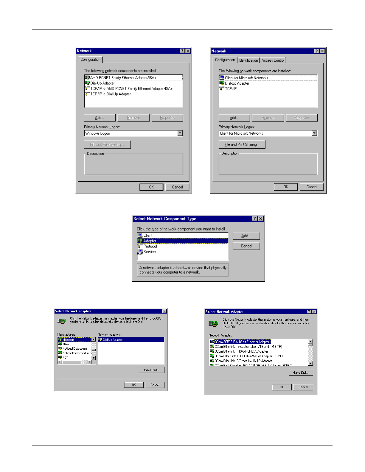
Chapter 7 - LAN Client Settings
Win95 Win98
3. Click Add. The Select Network Component Type dialog box opens.
4. Select Adapter, then click Add. The Select Network adapters dialog box opens.
Win95/98 WinNT
5. (Win95/98 only) In the Manufacturers option box, select Microsoft. In the Network Adapters
option box select Dial-up adapter.
Note: In Windows NT workstation there is no Manufacturers option box.
6. Click OK twice to return to and close the Network dialog box.
77
Page 78
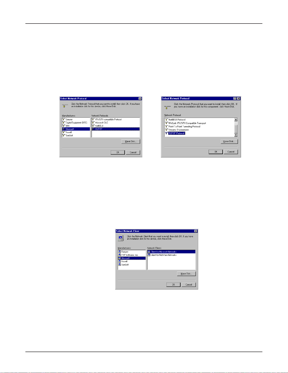
Chapter 7 - LAN Client Settings
Adding TCP/IP (Novell/NT Server Connection):
Windows 95/98/NT:
1. In the Network dialog box, Configuration tab, click Add.
2. Select Protocol and click Add.
3. The Select Network Protocol dialog box is displayed. In the Manufacturers option box [Win95
only], select Microsoft. In the Network Protocols option box, select TCP/IP [Win95/98] or TCP/
IP Protocol [WinNT only].
Note: Windows NT workstation has no Manufacturers option box.
Win95/98 WinNT
4. Click OK (twice) to return to, and then close, the Network dialog box.
Adding Client for Microsoft Networks (Novell/NT Server Connection):
Windows 95/98:
1. In the Network dialog box, Configuration tab, click Add.
2. Select Network Client and click Add.
3. The Select Network Client dialog box displays. In the Manufacturer’s option box, select
Microsoft. In the Network Clients option box, select Client for Microsoft Networks.
4. Click OK to add this Client and return to the Network dialog box.
Adding File and Print Sharing for Microsoft Networks
(Novell/NT Server Connection):
Windows 95/98:
1. In the Network dialog box, Configuration tab, click Add.
2. Select Services and click Add.
78
Page 79
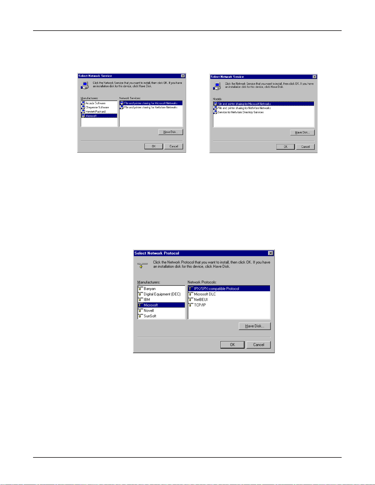
Chapter 7 - LAN Client Settings
3. The Select Network Service dialog box displays. In the Manufacturers option box, select
Microsoft. Select File and Printer sharing for Microsoft Networks.
Note: Windows 98 has no Manufacturers option box.
Win95 Win98
4. Click OK twice to return to and close the Network dialog box.
Adding IPX/SPX (Novell/NT Server Connection):
Windows 95/98:
1. In the Network dialog box, Configuration tab, click Add. The Select Network Component
Type dialog box opens.
2. Select Protocol and click Add. The Select Network Protocol dialog box opens.
3. In the Manufacturers option box, select Microsoft. In the Network Protocols option box, select
IPX/SPX-compatible Protocol.
4. Click OK twice to return to and close the Network dialog box.
Windows NT:
Note: NWLink IPX/SPX Compatible Transport is probably already installed, along with NWLink
NetBIOS and TCP/IP Protocol. However, if NWLink IPX/SPX Compatible Transport does not
appear on the Protocols tab of the Network dialog box, perform the following steps:
1. In the Network dialog box, Protocol tab, click Add. The Select Network Protocol dialog box
opens.
2. Select NWLink IPX/SPX Compatible T ransport , then click OK to return to the Network dialog
box.
3. Click Close to close the Network dialog box and return to the Desktop.
79
Page 80
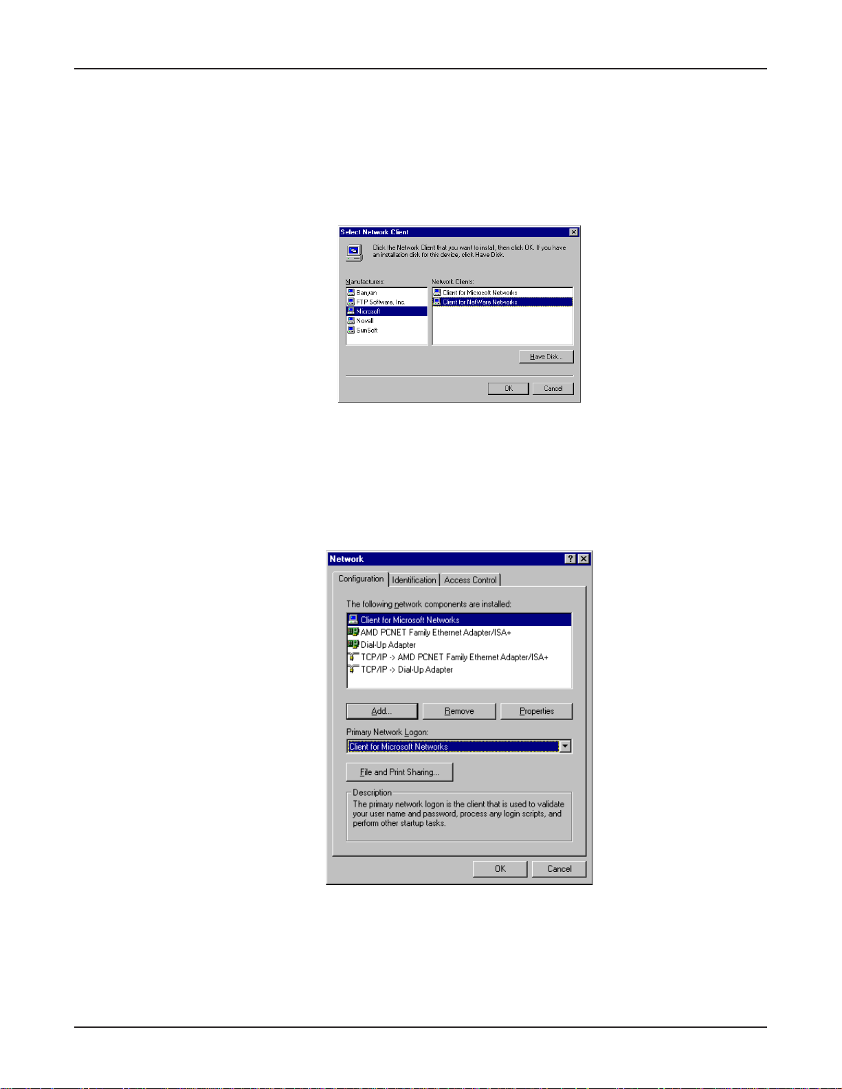
Chapter 7 - LAN Client Settings
Adding Client for NetWare Networks (Novell/NT Server Connection):
Windows 95/98:
1. In the Network dialog box, Configuration tab, click Add.
2. Select Network Client and click Add.
3. The Select Network Client dialog box displays. In the Manufacturer’s option box, select
Microsoft. In the Network Clients option box, select Client for NetWare Networks.
4. Click OK to add this Client and return to the Network dialog box.
Set Your Primary Network Logon (Novell/NT Server Connection):
Windows 95/98:
1. In the Primary Network Logon option box on Configuration tab of the Network dialog box,
select the previously installed Client for Microsoft Networks.
2. Click OK to close the Network dialog box.
80
Page 81
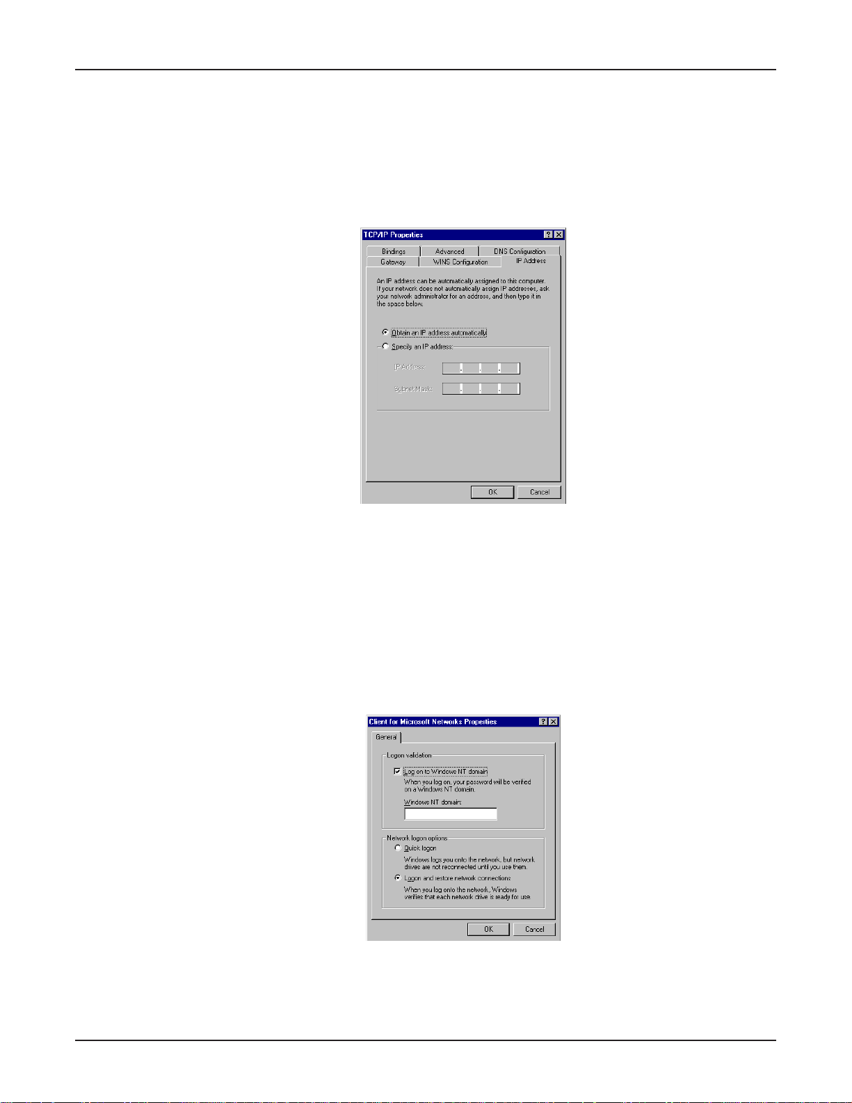
Chapter 7 - LAN Client Settings
Set Up Properties of Components (Novell/NT Server Connection):
Dial-up Adapter:
Windows 95/98:
1. In the Network dialog box, Configuration tab, select the TCP/IP-Dial-up adapter option.
2. Click Properties. The TCP/IP Properties dialog box opens with the IP Address tab selected.
3. Verify that Obtain an IP Address Automatically is selected.
4. Click OK to close the TCP/IP Properties dialog box.
Network Client:
Windows 95/98:
1. In the Network dialog box, Configuration tab, select Client for Microsoft Networks.
2. Click Properties. The Client for Microsoft Networks Properties dialog box opens.
3. On the General tab, select the Log on to Windows NT domain check box.
4. In the Windows NT domain box, enter the name of your Windows NT domain as provided by
your Network Administrator.
5. Click OK to return to the Network dialog box.
6. In the Network dialog box, Configuration tab, select Client for NetWare Networks.
7. Click Properties.
81
Page 82
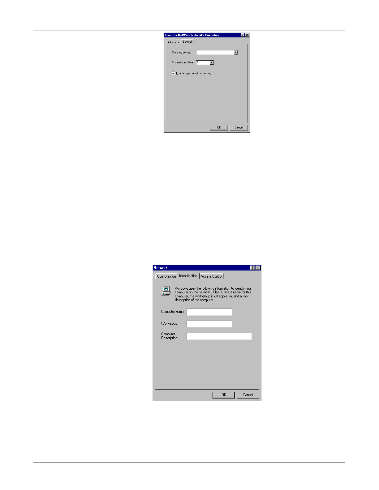
Chapter 7 - LAN Client Settings
8. On the General tab, in the Preferred server box, enter the name of your Novell Server Domain.
Select the First Network Drive and Enable Logon Script processing.
9. Click OK.
Network Protocol:
Windows 95/98:
1. In the Network dialog box, Configuration tab, select IPX/SPX Compatible Protocol.
2. Click Properties.
3. Disable Client for Microsoft Networks and File and Printer Sharing for Microsoft Networks.
This will ensure that when you log into your NT server, Windows will use the TCP/IP protocol.
Next, you must enable Client for Microsoft Networks.
Set Your Identification:
Windows 95/98:
1. In the Network dialog box, click the Identification tab.
2. In the Workgroup box, enter the name of your NT domain or the name of your workgroup as
provided by your Network Administrator.
3. Enter a name and description for your computer in the boxes provided.
4. Click OK.
82
Page 83
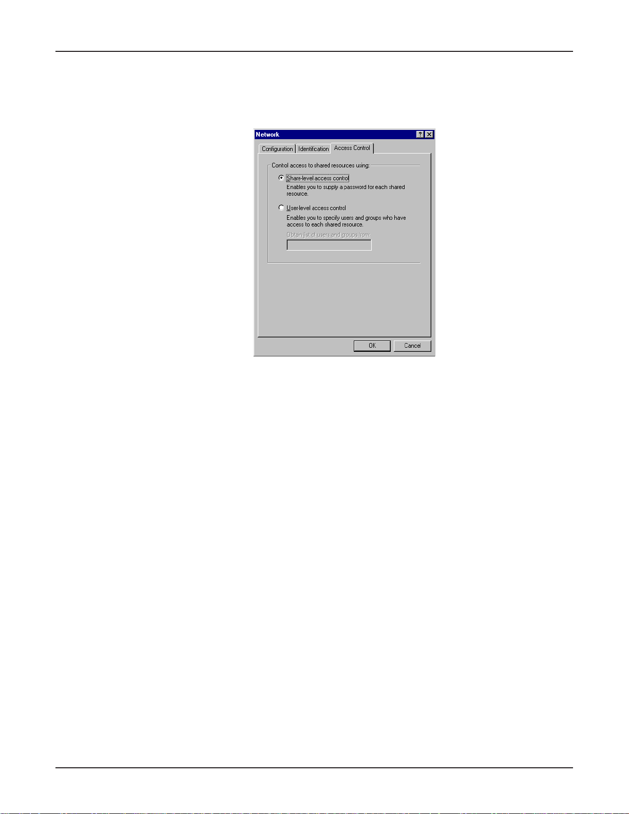
Chapter 7 - LAN Client Settings
Set Your Access Control:
Windows 95/98:
1. In the Network dialog box, click the Access Control tab.
2. In the Control Access to Shared resources using group, select Share-Level access control.
3. Click OK twice to return to and close the Network dialog box.
Note: You must restart your system for the new settings to take effect. Once your machine has
restarted, you may continue the configuration process.
Make Your New Connection (NT/Novell Server Connection):
Windows 95/98:
1. Double-click My Computer.
2. Double-click the Dial-Up Networking folder.
3. Double-click Make New Connection (or Add New Connection, Win98).
4. Follow the on-screen instructions to configure your connection.
Windows NT:
1. Double-click My Computer.
2. Double-click Dial-Up Networking.
3. When the Dial-Up Networking dialog box opens, click Install.
4. Follow the on-screen instructions to configure your connection.
Set Dial-up type (NT/Novell Server Connection):
Windows 95/98:
1. Right-click the newly created connection icon, then click Properties; the My Connection dialog
box opens.
2. On the General tab, click Server Type; the Server Types dialog box opens. Select PPP:
Windows 95, Windows NT 3.5, Internet.
3. Select only the following items: Log on to network, Enable software compression, and TCP/
IP. Do not change any other items that are already checked.
83
Page 84
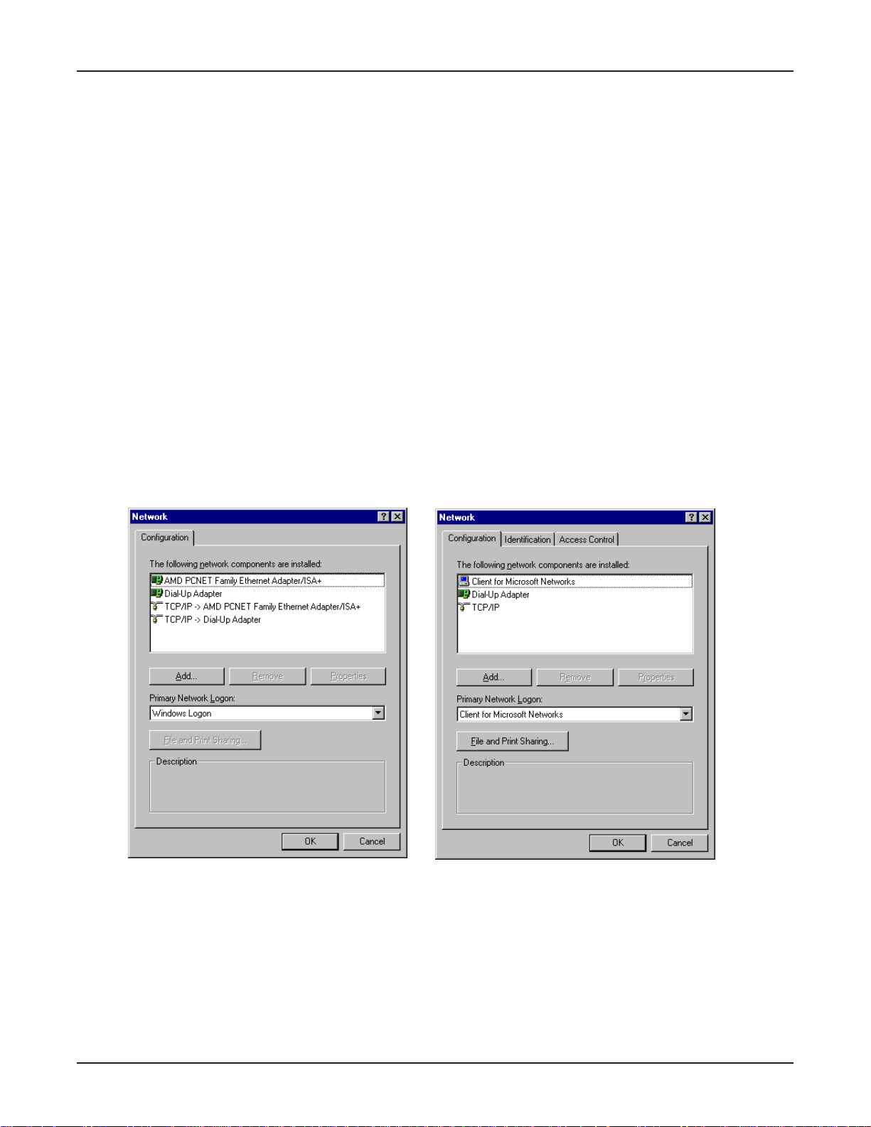
Chapter 7 - LAN Client Settings
Dial in to your network (NT/Novell Server Connection):
Windows 95/98:
1. You are ready to dial in to your network.
2. Double-click the new connection icon. The Connect To dialog box opens.
3. Enter the user name (if necessary) and password configured for you on the RF102S.
Note: If your particular situation permits, select Save password.
4. Click Connect.
5. After connecting to the RF102S, you can access the same services and resources as if you were
connected to the network locally .
Accessing a Unix Server
Perform the following procedures to prepare your PC workstation to access a remote Unix Server.
Adding the dial-up adapter (Unix Server Connection):
Windows 95/98/NT:
1. Click Start | Settings | Control Panel.
2. Double-click the Network icon to open the Network dialog box.
Win95 Win98
84
Page 85
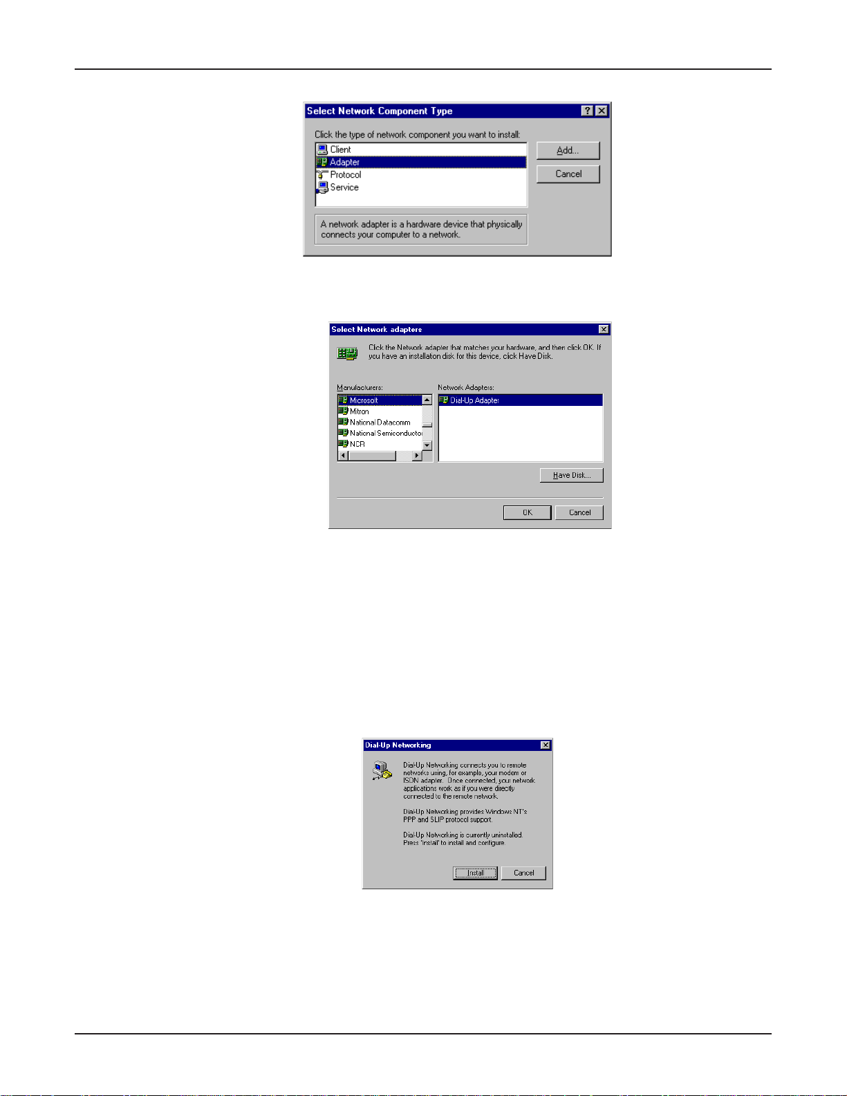
Chapter 7 - LAN Client Settings
3. Click Add. The Select Network Component Type dialog box opens.
4. Select Adapter, then click Add. The Select Network adapters dialog box opens.
Win95/98
5. In the Manufacturers list, select Microsoft. In the Network Adapters list, select Dial-up
adapter.
6. Click OK twice to return to and close the Network dialog box.
Windows NT:
Dial-up Networking adds PPP and SLIP protocol support, enabling your workstation to gain access to
a remote computer or network, even if your computer is not on a network.
1. Double-click My Computer, then double-click Dial-Up Networking. The following screen is
displayed:
2. Click Install, then follow the on-screen instructions to configure your connection.
85
Page 86
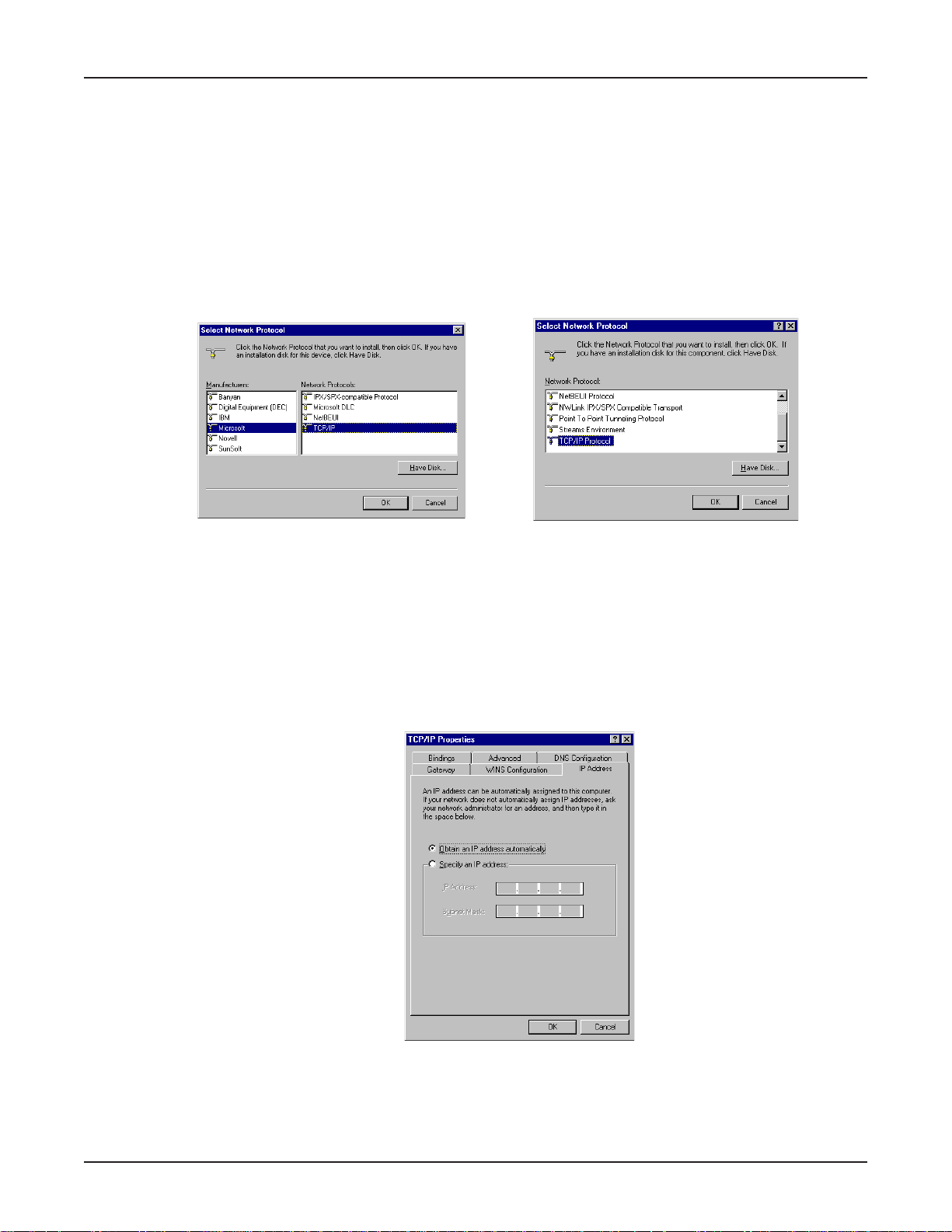
Chapter 7 - LAN Client Settings
Adding TCP/IP (Unix Server Connection):
Windows 95/98/NT:
1. In the Network dialog box, Configuration tab, click Add.
2. Select Protocol and click Add.
3. The Select Network Protocol dialog box is displayed. In the Manufacturers option box [Win95
only], select Microsoft. In the Network Protocols option box, select TCP/IP [Win95/98] or TCP/
IP Protocol [WinNT only].
Note: Windows NT workstation has no Manufacturers option box.
Win95/98 WinNT
4. Click OK (twice) to return to, and then close, the Network dialog box.
Set Up Properties of Components (Unix Server Connection):
Dial-up Adapter:
Windows 95/98:
1. In the Network dialog box, Configuration tab, select the TCP/IP-Dial-up adapter.
2. Click Properties. The TCP/IP Properties dialog box opens with the IP Address tab selected.
3. Verify that Obtain an IP Address Automatically is selected.
4. Click OK to close the TCP/IP Properties dialog box.
Note: You must restart your computers to enable the new settings.
86
Page 87

Chapter 7 - LAN Client Settings
Make Your New Connection (Unix Server Connection):
Windows 95/98:
1. Double-click My Computer.
2. Double-click the Dial-Up Networking folder.
3. Double-click Make New Connection (or Add New Connection, Win98).
4. Follow the onscreen instructions to configure your connection.
Windows NT:
1. Double-click My Computer.
2. Double-click Dial-Up Networking.
3. When the Dial-Up Networking dialog box opens, click Install.
4. Follow the onscreen instructions to configure your connection.
Set Dial-up type (Unix Server Connection):
Windows 95/98:
1. Right-click the newly created connection icon, then click Properties; the My Connection dialog
box opens.
2. On the General tab, click Server Type; the Server Types dialog box opens. Select PPP:
Windows 95, Windows NT 3.5, Internet.
3. Select only the following items: Log on to network, Enable software compression, and TCP/
IP. Note: do not disturb any other items that are already checked.
Dial in to your network (Unix Server Connection):
Windows 95/98:
1. You are ready to dial in to your network.
2. Double-click the new connection icon. The Connect To dialog box opens.
3. Enter the user name (if necessary) and password configured for you on the RF102S.
Note: If your particular situation permits, select the Save password check box.
4. Click Connect.
5. After connecting to the RF102S, you can access the same services and resources as if you were
connected to the network locally .
87
Page 88
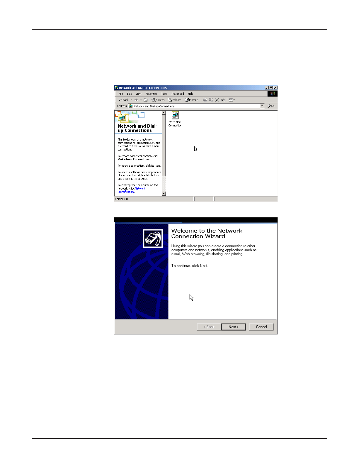
Chapter 7 - LAN Client Settings
Make New Connection (Windows 2000 only)
Perform the following procedures to prepare your Windows 2000 PC workstation to access any of the
remote servers and enable applications such as e-mail, Web browsing, file sharing, and printing.
1. Double-click My Computer.
2. Double-click the Network and Dial-up Connections folder.
3. Double-click Make New Connection.
4. Click Next, then follow the on-screen instructions to configure your connection.
88
Page 89

Chapter 8 - LAN-to-LAN Settings
Page 90

LAN -to- LAN Settings
Setting up LAN -to- LAN Routing
The majority of settings for LAN -to- LAN Routing are set up through RouteFinder Wizard or
RouteFinder Manager when IP routing (NAT disabled) is configured. This section provides an
overview of LAN -to- LAN Routing and shows you some of the benefits and limitations of LAN -toLAN Routing.
Setting up a Windows machine to share files
If you would like to share files over your network but don’t want to install a Windows NT server , you
can enable the file sharing feature of Windows. To set up file sharing:
Note: Each computer that you wish to share files among must be within the same workgroup. Use
the Identification tab of the Network Dialog box to define a workgroup name.
1. Select Start | Settings | Control Panel.
2. Click Network.
3. Click File and Printer Sharing.
4. To enable file sharing, select, “I want to be able to give others access to my files”.
Chapter 8 - LAN -to- LAN Settings
5. If you haven’t already done so, ensure that this computer has a fixed IP address on your local
network. Refer to the LAN Client Settings chapter for information on configuring a fixed IP
address.
6. After configuring and activating the fixed IP address, using My Computer or Windows Explorer,
right click the file or drive on the computer that you would like to share.
7. Select Sharing.
8. Enable sharing by selecting Shared As. Enter the name by which you would like this file or drive
to be known on your network.
9. You may now share the files on this computer.
90
Page 91
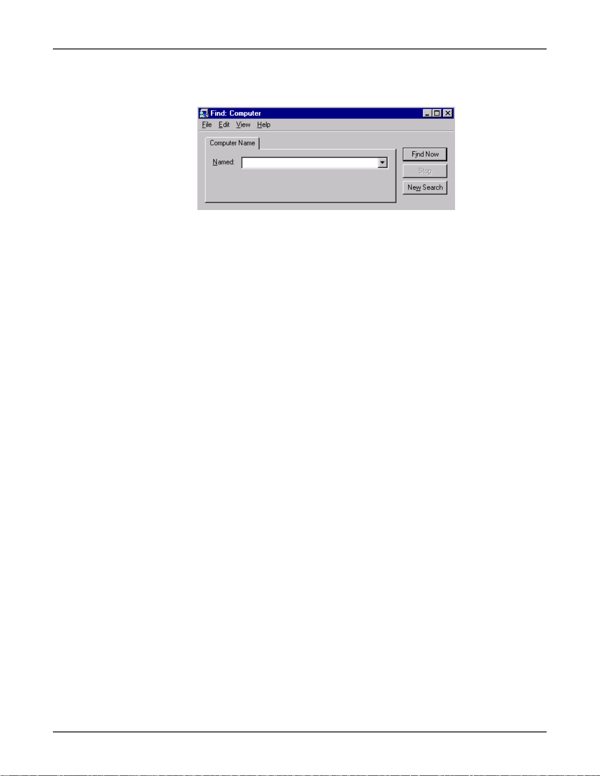
Chapter 8 - LAN -to- LAN Settings
Using the Find Computer command
If your clients are in different subnets or separated by a router, you will not be able to use the Find
Computer function within Windows by selecting Start | Find | Computer.
In the Find Computer dialog box, type the IP address of the computer you would like to find in the
Named field. If you choose a computer on a remote network, the network device will attempt to
establish a dial-up connection to the remote LAN based on settings entered in RouteFinder manager.
If you have entered the computer’s IP address and host name into your LMHosts file, you may enter
the computer’s host name, rather than the IP address in the Named field (refer to the following
LMHosts section of this User Guide).
Note: If the computer you are attempting to access is on a remote LAN, you may need to press Find
Now more than once while you wait for your network device to establish a dial-up connection to your
remote LAN.
Using LMHosts
Important: Each computer on the LAN must have a copy of this lookup table. Once you have
mapped the necessary computer or host names and IP addresses in the LMHosts file, copy this file
to the appropriate folder on each computer on the LAN. This file is located in your x:\Windows folder ,
where x: is the drive letter associated with the location of your windows operating system. Use
Windows Explorer, Tools | Find | Files or Folders option to search for LMHosts.
The LMHosts file can be edited using a text editor such as Notepad. At the end of the file, enter the
IP address, followed by a space, then the host or computer name. Add all necessary IP addresses
and computer names to the LMHosts file and save the file.
Once the LMHost file has been copied to each computer, the user will be able to enter the name of
the computer they want to access on the LAN without having to remember the IP address.
When using Find Computer, you may enter either an IP address or the computer’s host name if you
have entered the name and IP address in your LMHosts lookup table.
Note: Since the computers you’ll add to the LMHosts file are generally servers, only computers with
fixed IP addresses should be added to this file.
91
Page 92

Chapter 9 - Troubleshooting
Page 93

Troubleshooting
This chapter provides a list of common problems encountered while installing, configuring or
administering the RF102S. In the event you are unable to resolve your problem, refer to the Service,
Warranty and Technical Support chapter of this User Guide for information about contacting our
Technical Support representatives.
Common Problems
Problem #1
My computer can’t detect my RouteFinder on the LAN when I start one of the RouteFinder
Utilities (Device Not Found).
• Try pressing the Refresh Device List button.
• Unplug your network device and plug it back in, then press Refresh Device List.
• Verify that your computer has TCP/IP properly configured. You can check this by trying to
“ping” the computer you are using. If you can successfully ping the computer from itself, the
computer has TCP/IP correctly installed. Once you determine that you are able to ping the
computer, try to ping another computer in the same segment of your network. If this ping is
successful, your computer is properly connected to the network.
Chapter 9 - Troubleshooting
• Remove the TCP/IP Dial-up Adapter from your computer. For instructions, see Problem #2 in
this section.
• Verify that your network device is properly connected to your Ethernet hub by pressing Refresh
Device List in either RouteFinder Manager or RouteFinder Monitor. If your RouteFinder is
correctly connected, the WAN indicator light on your RouteFinder will flash. If no flash occurs, it
is not properly connected to the network. Reconnect your network device to the hub and try
again. If there is still no flash, it is possible the Ethernet cable or hub has a problem.
Problem #2
Other computers can connect to the network device, but my computer can’t.
Whenever I click on Internet Explorer or Netscape, I see the Windows Dial-up utility popping up
on my screen asking for my phone number and password to dial-up my ISP.
• Remove the TCP/IP dial-up adapter from all computers that will be using your RouteFinder to
access the Internet. TCP/IP dial-up adapter is not needed to use the RF102S to connect to the
Internet.
1. To remove the Dial-up Adapter, click Start | Settings | Control Panel.
2. Double-click the Network icon.
3. Click the Dial-up Adapter and press Remove. Restart the computer and try again.
• Verify that you have a correct IP address. From a DOS window in Windows 95/98, type
winipcfg. From Windows NT, type ipconfig. If the address field is listed as 0.0.0.0, the
computer does not have an IP address and you must ensure the automatic DHCP configuration
has been correctly set up for this computer.
• Verify that the W eb browser is properly configured to connect to the Internet via the LAN.
93
Page 94

Chapter 9 - Troubleshooting
Problem #3
The RouteFinder is connected to the modem, but has problems accessing the Internet.
• Verify that the workstation has TCP/IP properly configured.
• Attempt to ping the IP address of the RF102S.
• Use RouteFinder Monitor to see if the async port has successfully acquired a dynamic IP
address from the ISP, or if the static IP address is valid.
• Use Winipcfg (Windows 95/98) or ipconfig (Windows NT/ 2000) to check to see if the
computer’s IP settings are correct.
• Verify that the DNS settings are correct.
• Verify that the Gateway IP address is the device’s LAN Ethernet IP address (Server IP address).
• Verify that the IP address netmask is correct.
Problem #4
When I install the RouteFinder Utilities, I get the error message “missed export file
oleaut32.dll”
If you are using Windows 95/98, your computer has an old version of oleaut32.dll.
• Download the newest version of oleaut32.dll from the Microsoft web site (http://
www.microsoft.com).
• Create a backup of the file c:\windows\system\oleaut32.dll.
• Copy the new file to c:\windows\system\oleaut32.dll.
• After you have successfully copied the file, reinstall the RouteFinder Utilities.
• If you have problems with the new oleaut.dll file, use the backup file.
Problem #5
I configured my RouteFinder but I can’t get it to communicate with my modem.
• Check your initialization string. If you are using an ISDN TA and your ISDN TA was not listed as
a choice in Setup Wizard, refer to the ISDN TA User Guide for the appropriate initialization string.
• After verifying that the initialization string is correct, use the online Help in RouteFinder Monitor.
Problem #6
My RouteFinder dials-up a connection, but can’t seem to communication with the ISP.
• Verify that your baudrate is not set too high for your modem or ISDN TA. The maximum baudrate
that your modem or ISDN claims it can achieve may not be attainable due to poor line or
connection quality . Use RouteFinder Manager’s Modem settings menu to correct set the
baudrate to a lower rate and retry the connection.
• After lowering the baudrate, you are still not able to establish a connection, use the RouteFinder
Monitor’s online Help. If your connection still doesn’t work, contact your ISP.
Problem #7
Sometimes when I try and use the Internet or get my mail, the application can’t connect to the
Internet immediately .
• The most common reason for this is not due to a problem or error. If you are the first person to
make a connection to the Internet through the RF102S, there will be a delay when the Dial-OnDemand function automatically makes the connection and logs on to your ISP. Subsequent
users will be able to use the connection you have established without a delay .
94
Page 95

Chapter 9 - Troubleshooting
• If the scenario described above does not fit your situation, use RouteFinder monitor to view all
events that are taking place between the modem and your ISP as you attempt to make a
connection (for example, a busy signal).
Problem #8
After installing my RF102S, my modem connection seems to be slower.
• The RouteFinder device should have no effect on the modem speed. However , if more than one
client is using the same modem through the RouteFinder, the speed will be reduced.
• Run RouteFinder Monitor to view the number of concurrent client connections to your ISP.
Problem #9
While the Serial async ports are in use, my RF102S keeps dialing a connection to the Internet,
but no one is using the Internet.
• The RF102S will only dial the connection if there is a request from one of the computers on the
LAN for an IP address on the Internet. Keep in mind that certain applications can be configured
to request information from the Internet. For example, Microsoft Outlook can be set up to “check
for new mail every x minutes”. If this feature is enabled, Outlook will send a request for your
Internet POP3 server which will cause your RF102S to dial-up your ISP. To determine which
computer on your network is processing a request for an Internet connection, use the
RouteFinder Monitor. The event messages will provide information about which computer is
causing the RF102S to dial and which service (port#) the computer is requesting.
Problem #10
The “Please set the Device IP” screen displays when configuring the RF102S.
• This system detects that the RouteFinder’s LAN Ethernet IP address is not in the same subnet
as the PCs. Use RouteFinder Manager to set the RouteFinders’ IP address to the same network
as the PCs.
Problem #11
A message appears indicating the IP address you have inputted is either not valid on your
network or is in conflict with another IP address.
• The manager has detected the IP address of the RF102S you are configuring is in conflict with
another device. Turn of f the conflicting device and configure the RF102S using a dif ferent
Ethernet LAN IP address.
95
Page 96

Chapter 10 - Service, Warranty
and Technical Support
Page 97

Introduction
This chapter begins with the terms of your RouteFinder’s warranty . In the Software User License
Agreement section, you will find details about your software license agreement with Multi-Tech
Systems. The Technical Support section offers information about on-line registration as well as
phone numbers for contacting our Technical Support group. Also included in this chapter is
information about accessing our Internet site, and information about ordering accessories for your
RouteFinder.
Limited Warranty
Multi-Tech Systems, Inc., (hereafter “MTS”) warrants that the RouteFinder will be free from defects in
material or workmanship for a period of two years from date of purchase, or if proof of purchase is
not provided, two years from date of shipment.
MTS MAKES NO OTHER WARRANTY, EXPRESS OR IMPLIED, AND ALL IMPLIED WARRANTIES
OF MERCHANTABILITY AND FITNESS FOR A PARTICULAR PURPOSE ARE HEREBY
DISCLAIMED.
This warranty does not apply to any products which have been damaged by lightning storms, water,
or power surges or which have been neglected, altered, abused, used for a purpose other than the
one for which they were manufactured, repaired by Customer or any party without MTS’s written
authorization, or used in any manner inconsistent with MTS’s instructions.
Chapter 10 - Service, Warranty and Technical Support
MTS’s entire obligation under this warranty shall be limited (at MTS’s option) to repair or replacement
of any products which prove to be defective within the warranty period or, at MTS’s option, issuance
of a refund of the purchase price. Defective products must be returned by Customer to MTS’s factory
— transportation prepaid.
MTS WILL NOT BE LIABLE FOR CONSEQUENTIAL DAMAGES, AND UNDER NO
CIRCUMSTANCES WILL ITS LIABILITY EXCEED THE PRICE FOR DEFECTIVE PRODUCTS.
Addendum for North American Products
In the event that service is required, products may be shipped, freight prepaid, to our Mounds View ,
Minnesota, factory (Multi-T ech Systems, Inc., 2205 Woodale Drive, Mounds View, MN 551 12,
Attn: Repairs, Serial #_____). A Returned Materials Authorization (RMA) is not required. Return
shipping charges (surface) will be paid by MTS. Please include, inside the shipping box, a description
of the problem, a return shipping address (must have street address, not P.O. Box), a telephone
number, and if the product is out of warranty, a check or purchase order for repair charges.
Extended two-year overnight replacement agreements are available for selected products. Please
refer to our Overnight Replacement Agreement on our web site for details on rates and coverages.
Please direct your questions regarding technical matters, product configuration, verification that the
product is defective, etc., to our Technical Support department at 1-800-972-2439.
Please direct your questions regarding repair expediting, receiving, shipping, billing, etc., to our
Repair Accounting department at (800) 328-9717 or (763) 785-3500.
Repairs for damages caused by lightning storms, water, power surges, incorrect installation, physical
abuse, or user-caused damages are billed on a time-plus-materials basis.
97
Page 98

Chapter 10 - Service, Warranty and Technical Support
Addendum for International Products
Distributors should contact Amex, Inc., for information about the repairs for your Multi-Tech product.
Amex, Inc.
2724 Summer Street NE Minneapolis, MN 55413
U.S.A. Tel: +(763) 331-3251
Fax: +(763) 331-3180
Please direct your questions regarding technical matters, product configuration, verification that the
product is defective, etc., to our Technical Support department nearest you. When calling the U.S.,
please direct your questions regarding repair expediting, receiving, shipping, billing, etc., to our
Repair Accounting department at +(763) 785-3500 in the U.S.A., or a nearby Multi-Tech office which
is listed on the “Multi-Tech Corporate Offices” sheet in this International Distributor Resource Kit.
Repairs for damages caused by lightning storms, water, power surges, incorrect installation, physical
abuse, or user-caused damages are billed on a time-plus-materials basis.
Out of Warranty Repair Costs
Refer to Multi-Tech System's web site at http://www.multitech.com for information about out of
warranty repair costs.
98
Page 99

Chapter 10 - Service, Warranty and Technical Support
Software User License Agreement
IMPORTANT - READ BEFORE OPENING THE SOFTWARE PACKAGE
This license agreement is a legal agreement between you (either an individual or a single entity) and
Multi-Tech Systems, Inc. for the Multi-Tech software product enclosed, which includes computer
software and may include associated media, printed materials, and “online” or electronic
documentation (“SOFTWARE PRODUCT”). The SOFTWARE PRODUCT also includes any updates
and supplements to the original SOFTWARE PRODUCT provided to you by Microsoft. Any software
provided along with the SOFTWARE PRODUCT that is associated with a separate end-user license
agreement is licensed to you under the terms of that license agreement.
By installing, copying, downloading, accessing, or otherwise using the SOFTWARE PRODUCT, you
agree to be bound by the terms of this End User License Agreement (EULA). If you do not agree to
the terms of this EULA, do not install or use the SOFTWARE PRODUCT; you may, however, return it
to your place of purchase for a full refund.
SINGLE-USER SOFTWARE LICENSE AGREEMENT
This copy of Multi-Tech software is provided only on the condition that you, Customer, agree to the
following license. READ THIS LICENSE CAREFULLY. If you do not agree to the terms contained in
this license, return the packaged program UNOPENED to the place you obtained it. If you agree to
the terms contained in this license, fill out the enclosed Software Registration Card, date, sign and
return the card by mail. Opening the packaged program constitutes agreement to be bound by the
terms and conditions of this Software License Agreement. Your right to use the software terminates
automatically if you violate any part of this software license agreement.
MULTI-TECH SOFTWARE LICENSE AGREEMENT
Multi-Tech Systems, Inc. (MTS) agrees to grant and Customer agrees to accept on the following
terms and conditions, a non-transferable and non-exclusive license to use the software program(s)
delivered with this Agreement.
1. GRANT OF LICENSE. MTS grants Customer the right to use one copy of the software on a
single computer (the Licensed System). You may not network the software or otherwise use it
on more than one computer or computer terminal at the same time.
2. COPYRIGHT. The software is owned by MTS and is protected by United States copyright
laws and international treaty provisions. Therefore, Customer must treat the software like any
copyrighted material. Customer may install the software to a single hard disk and keep the
original for backup or archival purposes. Customer shall NOT copy, or translate into any
language, in whole or in part, any documentation which is provided by MTS in printed form
under this Agreement.
3. OTHER RESTRICTIONS. The software may not be assigned, sublicensed, translated or
otherwise transferred by Customer without prior written consent from MTS. Customer may
not reverse engineer, decompile, or disassemble the software. Any updates shall be used only
on the Licensed System, and shall remain subject to all other terms of this Agreement.
Customer agrees not to provide or otherwise make available the software including, but not
limited to documentation, programs listings, object code, or source code, in any form, to any
person other than Customer and his employees and /or agents, without prior written consent
from MTS. Customer acknowledges that the techniques, algorithms, and processes contained
in the software are proprietary to MTS and Customer agrees not to use or disclose such
information except as necessary to use the software.
Customer shall take reasonable steps consistent with steps taken to protect its own propri-
etary information to prevent the unauthorized copying or use by third parties of the software or
any of the other materials provided under this Agreement. Any previous version of the soft-
99
Page 100

Chapter 10 - Service, Warranty and Technical Support
ware must be destroyed or returned to Multi-Tech Systems, Inc. within 90 days of receipt of
the software upgrade or update.
4. WARRANTY. MTS warrants that the software will perform substantially in accordance to the
product specifications in effect at the time of receipt by Customer. If it fails to perform accordingly, MTS will optionally repair any defect, or replace it. This warranty is void if the failure has
resulted from accident, abuse, or misapplication. A signed Software Registration Card must
be on file at MTS for this warranty to be in effect.
THE FOREGOING WARRANTY IS IN LIEU ALL OTHER WARRANTIES, EXPRESSED OR
IMPLIED, INCLUDING, BUT NOT LIMITED TO, THE IMPLIED WARRANTIES OF MERCHANTABILITY AND FITNESS FOR A PARTICULAR PURPOSE. IN NO EVENT WILL MTS
BE LIABLE FOR CONSEQUENTIAL DAMAGES RESULTING FROM USE OF THE LICENSED PROGRAM, WHETHER AS A RESULT OF MTS NEGLIGENCE OR NOT, EVEN IF
MTS HAS BEEN ADVISED OF THE POSSIBILITY OF SUCH DAMAGES.
5. INDEMNIFICATION. MTS will indemnify and defend Customer from any claim that the soft-
ware infringes on any copyright, trademark, or patent. Customer will indemnify and defend
MTS against all other proceedings arising out of Customers use of the software.
6. GENERAL. If any of the provisions, or portions thereof, of this Agreement are invalid under
any applicable statute or rule of law, they are to that extent deemed to be omitted.
This is the complete and exclusive statement of the Agreement between the parties, which
supersedes all proposals, oral, written and all other communications between the parties
relating to the subject matter of this Agreement. This Agreement may only be amended or
modified in writing, signed by authorized representatives of both parties.
This Agreement shall be governed by the laws of the State of Minnesota.
The waiver of one breach or default hereunder shall not constitute the waiver of any subse-
quent breach or default.
100
 Loading...