

Page 1

OPERATIONS & PARTS MANUAL
SERIES
MODEL ST-45HRM
STRUCTURAL CONCRETE PUMP
(HATZ DIESEL ENGINE)
FINAL REVISION
Revision #4 (07/16/04)
THIS MANUAL MUST ACCOMPANY
THE EQUIPMENT AT ALL TIMES.
Page 2
Proposition 65 W arning
PAGE 2 — MAYCO ST-45HRM PUMP — OPERATION & PARTS MANUAL — REV. #4 (07/16/04)
Page 3

HERE'S HOW TO GET HELP
HERE'S HOW TO GET HELP
PLEASE HAVE THE MODEL AND SERIAL
NUMBER
MULTIQUIP CORPORATE OFFICE
18910 Wilmington Ave. 800-421-1244
Carson, CA 90746
Email: mq@multiquip.com
Internet: www.multiquip.com
PARTS DEPARTMENT
800-427-1244
310-537-3700
MAYCO PARTS
800-306-2926
310-537-3700
SERVICE DEPARTMENT
800-421-1244
310-537-3700
TECHNICAL ASSISTANCE
800-478-1244
WARRANTY DEPARTMENT
800-421-1244,
310-537-3700,
ON-HAND
EXT.
279
EXT.
279
WHEN CALLING
FAX:
310-537-3927
FAX:
800-672-7877
FAX:
310-637-3284
FAX:
800-672-7877
FAX:
310-637-3284
FAX:
310-537-4259
FAX:
310-631-5032
FAX:
310-537-1173
© COPYRIGHT 2004, MULTIQUIP INC.
Multiquip Inc, the MQ logo and the Mayco logo are registered trademarks of Multiquip Inc. and may not be used, reproduced, or
altered without written permission. All other trademarks are the property of thier respective owners and used with permission.
This manual
should remain with the unit if resold.
The information and specifications included in this publication were in effect at the time of approval for printing. Illustrations are
based on the
manual are for guidance only and may not be considered as binding. Multiquip Inc. reserves the right to discontinue or change
specifications, design or the information published in this publication at any time without notice and without incurring any obligations.
MUST accompany the equipment at all times. This manual is considered a permanent part of the equipment and
Mayco ST-45HRM w/ Hatz Diesel Engine.
Illustrations, descriptions, references and technical data contained in this
To find the latest revision of this
publication, visit our website at:
www.multiquip.com
MAYCO ST-45HRM PUMP — OPERATION & PARTS MANUAL — REV. #4 (07/16/04) — PAGE 3
Page 4

TABLE OF CONTENTS
MAYCO ST-45HRM
STRUCTURAL CONCRETE
PUMP
Proposition 65 Warning .............................................2
Here’s how To Get Help............................................. 3
Table of Contents ...................................................... 4
Parts Ordering Procedures ...................................... 5
Pump Specifications ..................................................6
Engine Specifications ................................................ 7
Dimensions .............................................................. 8
Safety Message Alert Symbols .......................... 9-10
Rules for Safe Operation ................................... 11-13
Operation and Safety Decals ............................ 14-15
Important Hand Signals ..........................................16
General Information .......................................... 17-18
How it Works............................................................ 19
Pump Components ........................................... 20-21
Control Box Components ........................................ 22
Engine Components ...............................................23
Operating Procedures....................................... 24-28
Inspection .......................................................... 29-31
Initial Start-Up Procedure ................................. 32-35
Towing Guidelines ............................................. 36-37
Trailer Safety Guidelines ................................... 38-40
Towing Information ............................................ 41-42
Wiring Diagram (Tail Lights) ....................................43
Maintenance (Pump) ........................................ 44-52
Hydraulic Hose Connections ............................. 54-56
Manifold Port Locations ...........................................57
Appendix — Concrete Mix Information ............. 58-59
Appendix — Slump Test Procedure ........................60
Troubleshooting (Engine) ........................................61
Troubleshooting (Hydraulic System) ....................... 62
Troubleshooting (Electrical System) ....................... 63
Troubleshooting (Brake System).............................64
PARTS ILLUSTRATIONS
Explanation Of Code In Remarks Column .............. 64
Suggested Spare Parts ...........................................65
Appendix — Recommended
Shotcrete System ............................... 66
Appendix — Recommended
Shotcrete Accessories ........................ 68
Decal Placement ................................................70-71
Axle Assembly ....................................................74-75
Brakeline Assembly ............................................76-77
Hopper Assembly ...............................................78-79
Hopper Attachment Assembly ........................... 80-81
Hopper Interior Assembly ..................................82-83
Shuttle Cylinder Assembly ................................. 84-85
Fuel and Hydraulic Tank Assembly .................... 86-89
Front Cover Assembly........................................ 90-91
Heat Exchanger Assembly .................................92-93
Engine and Frame Assembly .............................94-96
Throttle and Water Filter Assembly ....................96-97
Hydraulic Pump Assembly ................................. 98-99
Lubrication Pistons Assembly ........................100-101
Electrical System Assembly ........................... 102-103
Accumulator Assembly...................................104-105
Manifold Assembly .........................................106-107
Remixer Control Assembly .............................108-109
Battery Assembly ...........................................110-111
Lubrication Panel ........................................... 112-113
Taillight Assembly ...........................................114-115
Control Box Interior Door Assembly...............116-117
Control Box Mounting Assembly ...................118-119
Control Box Assembly ...................................120-121
Control Box Door Wiring Diagram ......................... 122
Control Box Interior Wiring Diagram ..................... 123
Terminal Block Wiring Diagram ............................. 124
Control Box Electrical Schematic ................... 125-126
Interconnect Hydraulic Control Box ...................... 127
Hydraulic Diagram ............................................... 128
Optional Radio Control.......................................... 129
NOTE
PAGE 4 — MAYCO ST-45HRM PUMP — OPERATION & PARTS MANUAL — REV. #4 (07/16/04)
Specification and part
number are subject to
change without notice.
Terms and Conditions Of Sale — Parts ................ 130
Mayco Pump Warranty .......................................... 131
Page 5

PARTS ORDERING PROCEDURES
When ordering parts,
please supply the following information:
❒❒
❒ Dealer account number
❒❒
❒❒
❒ Dealer name and address
❒❒
❒❒
❒ Shipping address (if different than billing address)
❒❒
❒❒
❒ Return fax number
❒❒
❒❒
❒ Applicable model number
❒❒
❒❒
❒ Quantity, part number and description of each part
❒❒
❒❒
❒ Specify preferred method of shipment:
❒❒
✓ FedEx or UPS Ground
✓ FedEx or UPS Second Day or Third Day
✓ FedEx or UPS Next Day
✓ Federal Express Priority One
✓ DHL
✓ Tr u c k
Note: Unless otherwise indicated by customer, all
orders are treated as “Standard Orders”, and will
ship within 24 hours. We will make every effort to ship
“Air Shipments” the same day that the order is
received, if prior to 2PM west coast time. “Stock
Orders” must be so noted on fax or web forms.
Here’s how to get help...
Please have the model and serial number
on hand when calling.
MULTIQUIP CORPORATE OFFICE
18910 Wilmington Ave. 800-421-1244
FAX:
Carson, CA 90746
Email: mq@multiquip.com
Internet: www.multiquip.com
PARTS DEPARTMENT
800-427-1244
310-537-3700
MAYCO PARTS
800-306-2926
310-537-3700
SERVICE DEPARTMENT
800-421-1244
310-537-3700
TECHNICAL ASSISTANCE
800-478-1244
WARRANTY DEPARTMENT
800-421-1244,
310-537-3700,
EXT.
EXT.
279
279
310-537-3927
FAX:
800-672-7877
FAX:
310-637-3284
FAX:
800-672-7877
FAX:
310-637-3284
FAX:
310-537-4259
FAX:
310-631-5032
FAX:
310-537-1173
Place Your Parts Order Via Web or Fax
For Even More Savings!
(Domestic USA Dealers Only)
Extra Discounts!
All parts orders which include complete part numbers and
are received by our automated web parts order system, or
by fax qualify for the following extra discounts:
Ordered Standard Stock orders
via orders ($750 list and above)
Fax 3% 10%
Web 5% 10%
Special freight allowances
when you order 10 or more
line items via Web or Fax!**
FedEx Ground Service
No other allowances on freight shipped by any other carrier.
**Common nuts, bolts and washers (all items under $1.00
list price) do not count towards the 10+ line items.
NOTE: DISCOUNTS ARE SUBJECT TO CHANGE
at no charge for freight
MULTIQUIP INC.
18910 WILMINGTON AVENUE
POST OFFICE BOX 6254
CARSON, CALIFORNIA 90749
310-537-3700 • 800-421-1244
FAX: 310-537-3927
E-MAIL: mq@multiquip.com
INTERNET: www.multiquip.com
MAYCO ST-45HRM PUMP — OPERATION & PARTS MANUAL — REV. #4 (07/16/04) — PAGE 5
Direct TOLL-FREE access
to our Parts Department:
Toll-free nationwide — 800-427-1244
Toll-free FAX — 800-6-PARTS-7
(800/672-7877)
Page 6

ST-45 PUMP — PUMP SPECIFICATIONS
dohteMgnipmuPnotsiPgnitacorpiceR
etaRgnipmuP*ruohrep.sdy.uc54otpU
eziSetagerggAmumixaM)mm83(sunim.ni2/1-1
t
hgieHgnipmuPlacitreV)m67(.tf052fossecxEotpU
ecnatsiDgnipmuPlatnoziroH*)m503(.tf0001
snoitacificepSpmuP54-TS.1elbaT
LrednilyC)sretiL5.62(snollaG7
yticapaCxoBnoitacirbu
yticapaCdiulFciluardyH)sretiL912(snollaG85
yticapaCknaTleuF)sretiL67(snollaG02
yticapaCreppoHreximerver/dwflanoitpohtiw.tf.uc01
esoHlairetaM
)elbac.tf52(lortnoCetomeRlanoitpo
snoisnemiD61egaPeeS
)sdiulfhtiw(thgieW)gk472,9(.sbl602,4
gieW)gk809,8(.sbl040,4
)gnippihs/yrd(th
.aid.ni5,.ni4,.ni3
)mm721,mm6.101,mm2.67(
eziSeriT)mm653xmm781(.ni41x.ni53.7
PAGE 6 — MAYCO ST-45HRM PUMP — OPERATION & PARTS MANUAL — REV. #4 (07/16/04)
snotitidnocetisbojdnadesuezisenil,pmuls,ngisedximnognidnepedyravlliwtuptuoemuloV*
Page 7

ST-45 PUMP — ENGINE SPECIFICATIONS
ledoMENIGNELESEIDPH7514M3ZTAH
snoitacificepSenignE.2elbaT
ekortSXeroB
.ni31.4x.ni20.4
)mm501x201(
oitaRnoisserpmoC7.81
D)cc375,2(.uc751
tnemecalpsi
yticapaCliOebuL
niM/xaM
.tq4.5/.tq1.9
)L1.5/L6.8(
enignE
deepSenignE
001±mpr578
eldIlluF
epyTyrettaB)
hA341/88(V21
)edarGliO(03-W01EAS
noitacirbuLenignE
)ssalCecivreS(FSroGS
dohteMgnitratStratScirtcelE
thgieWteNyrD)gk552(sbl265
MAYCO ST-45HRM PUMP — OPERATION & PARTS MANUAL — REV. #4 (07/16/04) — PAGE 7
Page 8
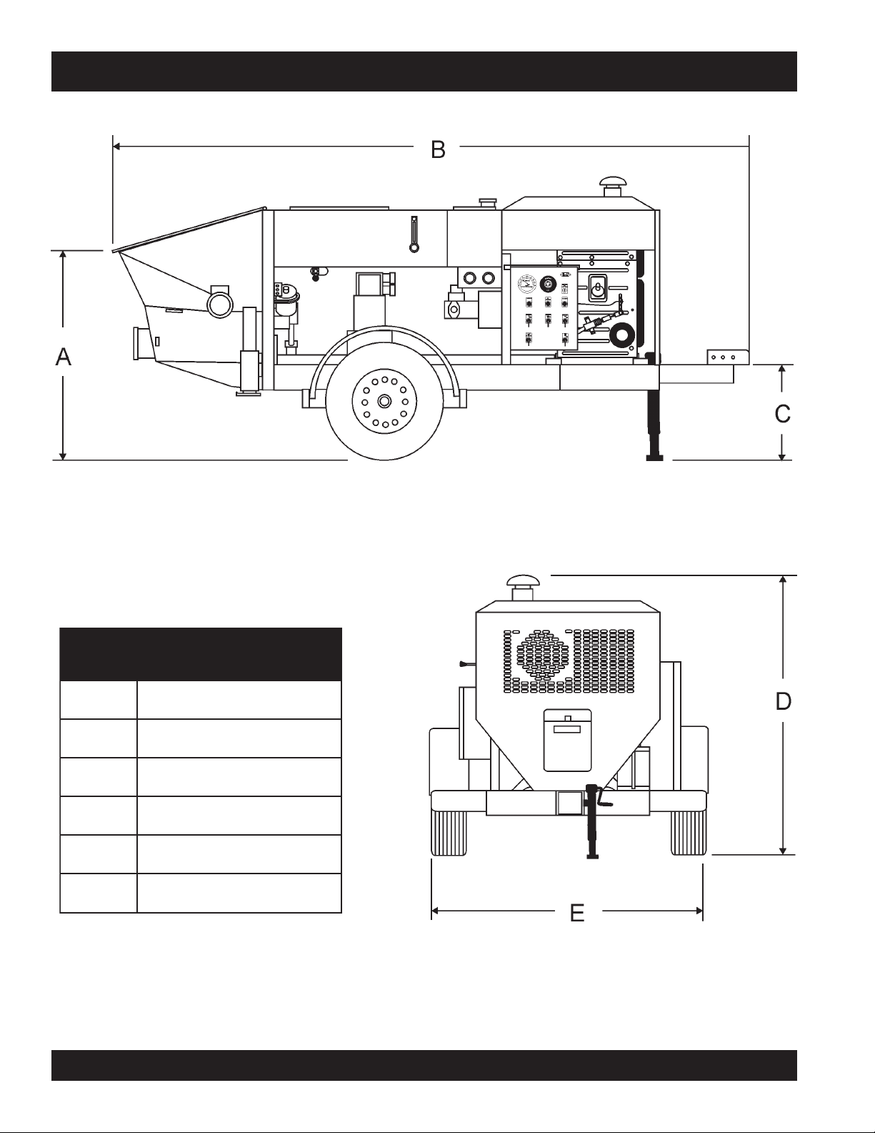
ST-45 PUMP — DIMENSIONS
SNOISNEMID.3ELBAT
.FERSNOISNEMID
A).mc3.411(.ni54
B).mc5.114(.ni261
C).mc16(.ni42
D).mc4.581(.ni37
E).mc2.271(.ni86
Figure 1. ST-45 Structural Concrete Pump Dimensions
PAGE 8 — MAYCO ST-45HRM PUMP — OPERATION & PARTS MANUAL — REV. #4 (07/16/04)
Page 9

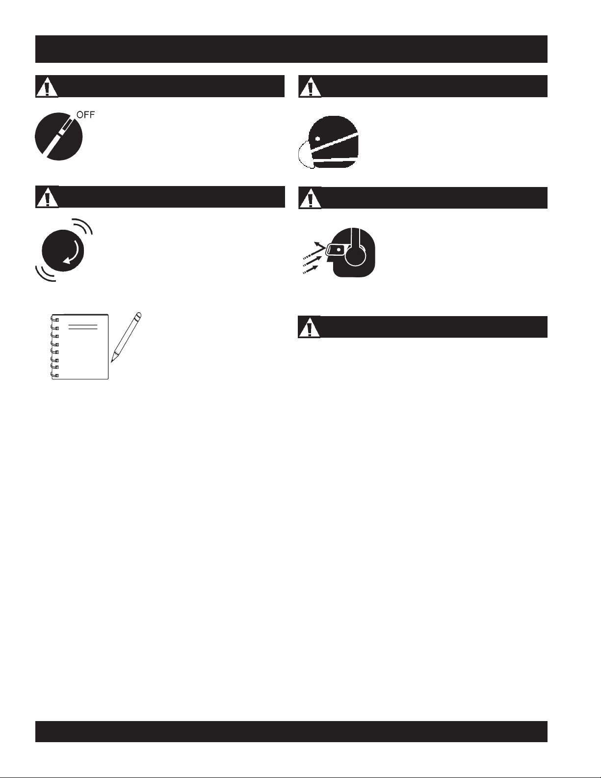
ST-45 PUMP — SAFETY MESSAGE ALERT SYMBOLS
FOR YOUR SAFETY AND THE SAFETY OF OTHERS!
Safety precautions should be followed at all times when operating
this equipment. Failure to read and understand the Safety
Messages and Operating Instructions could result in injury to
yourself and others.
This Owner's Manual has been
developed to provide complete
NOTE
Before using this pump , ensure that the operating
individual has read and understands all instructions in this
manual.
instructions for the safe and efficient
operation of the Multiquip Mayco
ST-45 Structural Concrete
Refer to the engine manufacturers
instructions for data relative to its safe
operation.
pump.
HAZARD SYMBOLS
SAFETY MESSAGE ALERT SYMBOLS
The three (3) Safety Messages shown below will inform you
about potential hazards that could injure you or others. The
Safety Messages specifically address the level of exposure to
the operator, and are preceded by one of three words: DANGER,
Lethal Exhaust Gases
Diesel engine exhaust gases contain poisonous
carbon monoxide. This gas is colorless and
odorless, and can cause death if inhaled.
NEVER operate this equipment in a confined
area or enclosed structure that does not
provide ample free flow air.
Explosive Fuel
Diesel fuel
vapors can cause an explosion if ignited. DO
NOT start the engine near spilled fuel or
combustible fluids. DO NOT fill the fuel tank
while the engine is running or hot. DO NOT
overfill tank, since spilled fuel could ignite if it
comes into contact with hot engine parts or
sparks from the ignition system. Store fuel in
approved containers, in well-ventilated areas
and away from sparks and flames. NEVER
use fuel as a cleaning agent.
is extremely flammable, and its
DANGER: You WILL be KILLED or
SERIOUSLY injured if you do not follow
directions.
WARNING: You CAN be KILLED or
SERIOUSLY injured if you do not follow
directions.
CAUTION: You CAN be injured if you
do not follow directions
Potential hazards associated with operation of the pump will be
referenced with Hazard Symbols which appear throughout this
manual, and will be referenced in conjunction with Safety
Message Alert Symbols.
Burn Hazards
Engine components can generate extreme heat.
To prevent burns, DO NOT touch these areas
while the engine is running or immediately after
operations. NEVER operate the engine with
heat shields or heat guards removed.
Rotating Parts
NEVER operate equipment with covers, or
guards removed. Keep
and clothing away from all moving parts to
prevent injury.
fingers, hands, hair
MAYCO ST-45HRM PUMP — OPERATION & PARTS MANUAL — REV. #4 (07/16/04) — PAGE 9
Page 10
ST-45 PUMP — SAFETY MESSAGE ALERT SYMBOLS
Accidental Starting
ALWAYS place the ON/OFF switch in the OFF
position. NEVER perform maintenance on the
unit with the ignition key in the ON position.
Over Speed Conditions
NEVER tamper with the factory settings of the
engine governor or settings. Personal injury
and damage to the engine or equipment can
result if operating in speed ranges above
maximum allowable.
This
pump
surrounding environment could
NOTE
be damaged if you do not follow
instructions.
, other property, or the
Respiratory Hazard
ALWAYS wear approved
protection.
respiratory
Sight and Hearing hazard
ALWAYS wear approved
hearing
protection.
eye
and
Equipment Damage Messages
Other important messages are provided throughout this manual
to help prevent damage to your concrete pump, other property,
or the surrounding environment.
PAGE 10 — MAYCO ST-45HRM PUMP — OPERATION & PARTS MANUAL — REV. #4 (07/16/04)
Page 11

ST-45 PUMP — RULES FOR SAFE OPERATION
■
CAUTION:
Failure to follow instructions in this manual may
death!
lead to serious injury or even
equipment is to be operated by trained and
qualified personnel only! This equipment is
for industrial use only.
The following safety guidelines should always be used when
operating the ST-45 structural concrete ump:
GENERAL SAFETY
■
DO NOT operate or service this equipment
before reading this entire manual.
■
This equipment should not be operated by persons under 18
years of age.
■
NEVER operate this equipment without proper protective
clothing, shatterproof glasses, steel-toed boots and other
protective devices required by the job.
■
NEVER operate this equipment when not feeling
well due to fatigue, illness or taking medicine.
■
NEVER operate this equipment under the
influence or drugs or alcohol.
■
ALWAYS check the machine for loosened threads or bolts
before starting.
■
ALWAYS wear proper respiratory (mask),
protection equipment when operating the pump .
hearing
This
and
eye
Whenever necessary, replace nameplate, operation and
safety decals when they become difficult read.
■
Manufacture does not assume responsibility for any accident
due to equipment modifications.
■
NEVER use accessories or attachments, which are not
recommended by Multiquip for this equipment. Damage to
the equipment and/or injury to user may result.
■
NEVER touch the hot exhaust manifold,
muffler or cylinder. Allow these parts to
cool before servicing engine or pump .
■
High Temperatures – Allow the engine to cool before adding
fuel or performing service and maintenance functions. Contact
with
■
The engine section of this pump requires an adequate free
flow of cooling air.
■
ALWAYS refuel in a well-ventilated area, away from sparks
and open flames.
■
ALWAYS use extreme caution when
working with flammable liquids. When
refueling, stop the engine and allow it to
cool.
■
NEVER
Fire or explosion could result from
vapors
hot!
components can cause serious burns.
smoke
NEVER
around or near the machine.
operate the pump in any enclosed
or narrow area where free
flow of the air is restricted. If
the air flow is restricted it
will cause serious damage
to the pump or engine and
may cause injury to
people. Remember the
pump's engine gives off
DEADLY
gas.
carbon monoxide
fuel
, or if fuel is spilled on a
hot!
engine.
■
NEVER operate the pump in an explosive
atmosphere or near combustible materials. An explosion or
fire could result causing severe
■
Topping-off to filler port is dangerous, as it tends to spill fuel.
MAYCO ST-45HRM PUMP — OPERATION & PARTS MANUAL — REV. #4 (07/16/04) — PAGE 11
bodily harm or even death.
Page 12

ST-45 PUMP — RULES FOR SAFE OPERATION
■
ALWAYS remove the
unattended.
■
ALWAYS block the
ignition key
wheels
on the unit when using on a
when leaving the pump
Transporting
■
■
slope.
■
ALWAYS maintain this equipment in a safe operating
■
condition at all times.
■
ALWAYS stop the engine before servicing, adding fuel or oil.
■
NEVER run engine without air filter. Severe engine damage
may occur.
■
ALWAYS be sure the operator is familiar with proper safety
precautions and operation techniques before using pump.
■
ALWAYS store equipment properly when it is not being used.
Equipment should be stored in a clean, dry location out of
the reach of children.
■
DO NOT operate this equipment unless all guards and safety
Towing
■
■
■
■
devices are attached and in place.
■
CAUTION must be exercised while servicing this equipment.
■
Rotating and moving parts can cause injury if contacted.
■
Keep all
from the equipment at all times.
■
Before start-up, check the hopper and remove all foreign
matter and debris.
inexperienced
and
unauthorized
people away
■
■
■
ALWAYS shutdown engine before transporting the pump.
Tighten fuel tank cap securely and close fuel valve to prevent
fuel from spilling.
Drain fuel when transporting pump over long distances or
bad roads.
Before towing, check the hitch and secure the safety chain to
the towing vehicle.
When towing, an adequate safety chain must be fastened to
the frame, refer to Towing Guidelines.
Tow only with a vehicle and hitch rated to pull a 5,000 lbs.
load.
If unit is equipped with ball hitch coupler, use only 2" all steel
ball rated for minimum of 5,000 lbs. Use 1" hardened steel
pull pin, if not equipped with ball hitch.
This equipment shall not be towed or operated by individuals
who cannot read understand the signs, decals or operating
instructions.
When towing at night,
always
have rear tail lights ON.
DO NOT tow unit with hopper full of material.
DO NOT tow unit with hoses attached.
■
DO NOT use worn or damaged hose couplings, inspect all
■
hoses and couplings for wear. Replace any worn or defective
hose or couplings immediately.
■
Keep hands out of the hopper when the engine is running.
■
DO NOT operate unit with the
■
DO NOT disconnect hose couplings or nozzle while under
hood open
.
Maintenance Safety
■
■
pressure. Relieve pressure by manually activating pressure
relief valve at manifold.
■
Unauthorized equipment modifications will void all
■
■
warranties.
■
Check all fasteners periodically for tightness. Also check
■
towing tongue bolt, lock nut and wheel lug nuts for wear.
■
Test the
pump's ON/OFF
switch. The purpose of this test is
■
to shut down the engine.
■
Refer to the
technical questions or information
HATZ Engine Owner's Manual
for engine
recommended by
Multiquip for this equipment. Damage to the equipment and
or injury to user may result.
DO NOT tow unit in excess of 45 MPH on highways..
NEVER lubricate components or attempt service on a running
pump .
ALWAYS allow the pump a proper amount of time to cool
before servicing.
Keep the pump in proper running condition.
Fix damage to the pump immediately and always replace
broken parts.
Dispose of hazardous waste properly. Examples of potentially
hazardous waste are used motor oil, fuel and fuel filters.
DO NOT use plastic containers to dispose of hazardous
waste.
PAGE 12 — MAYCO ST-45HRM PUMP — OPERATION & PARTS MANUAL — REV. #4 (07/16/04)
Page 13

ST-45 PUMP — RULES FOR SAFE OPERATION
Battery
The battery contains acids that can cause injury to the eyes and
skin. To avoid eye irr itation,
insulated gloves when picking up the battery. Use the following
guidelines when handling the battery:
1. DO NOT drop the battery. There is the possibility of risk that the
battery may explode.
2. DO NOT expose the battery to open
flames, sparks, cigarettes etc. The
battery contains combustible gases
and liquids. If these gases and liquids
come in contact with a flame or spark,
an explosion could occur.
3. ALWAYS keep the battery charged. If the battery is not charged
a buildup of combustible gas will occur.
4. ALWAYS keep battery charging and cables in good working
condition. Repair or replace all worn cables.
5. ALWAYS recharge the battery in an vented air environment,
to avoid risk of a dangerous concentration of combustible
gases.
always
wear safety glasses. Use well
Emergencies
■
ALWAYS know the location of the nearest
■
ALWAYS know the location of the nearest and
■
In emergencies
nearest phone or
Also know the phone numbers of the nearest
ambulance, doctor
information will be invaluable in the case of an
emergency.
fire extinguisher
first aid kit
always
know the location of the
keep a phone on the job site
and
fire department
.
. This
.
.
6. In case the battery liquid (dilute sulfuric acid) comes in contact
with
clothing or skin
plenty of water.
7. In case the battery liquid (dilute sulfuric acid) comes in contact
with your eyes, rinse eyes immediately with plenty of water,
then contact the nearest doctor or hospital, and seek medical
attention.
, rinse skin or clothing immediately with
MAYCO ST-45HRM PUMP — OPERATION & PARTS MANUAL — REV. #4 (07/16/04) — PAGE 13
Page 14
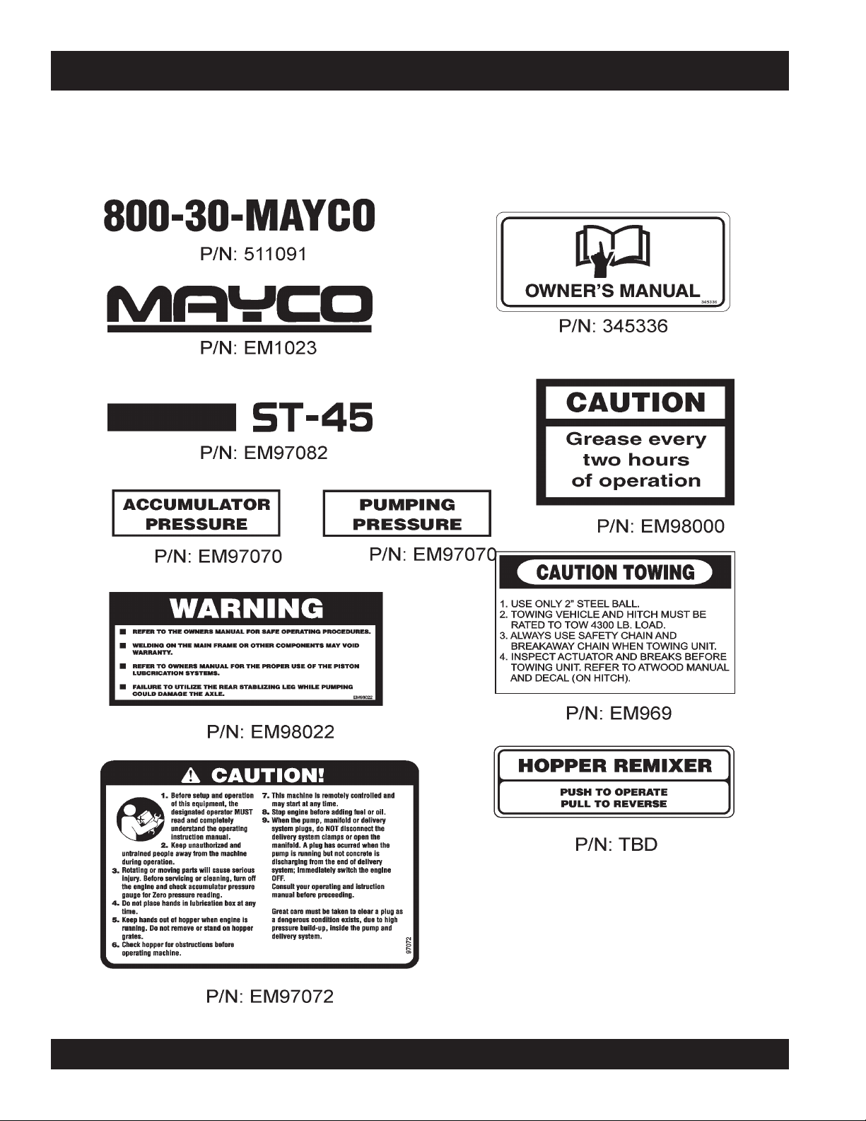
ST-45 PUMP — OPERATION AND SAFETY DECALS
Machine Safety Decals
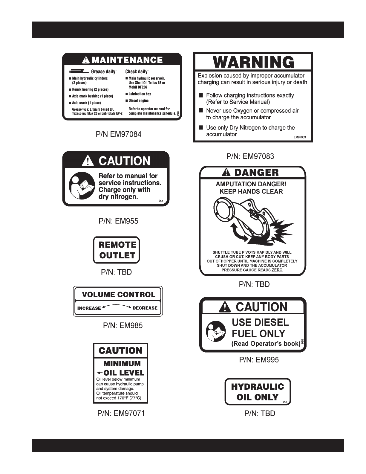
The ST-45 structural concrete pump is equipped with a number of safety decals. These decals are provided for operator safety and
maintenance information. Figure 1 below illustrates these decals as they appear on the machine. Should any of these decals
become unreadable, replacements can be obtained from your dealer.
Figure 2. ST-45 Operation and Safety Decals
PAGE 14 — MAYCO ST-45HRM PUMP — OPERATION & PARTS MANUAL — REV. #4 (07/16/04)
Page 15
ST-45 PUMP — OPERATION AND SAFETY DECALS
Figure 3. ST-45 Operation and Safety Decals
MAYCO ST-45HRM PUMP — OPERATION & PARTS MANUAL — REV. #4 (07/16/04) — PAGE 15
Page 16
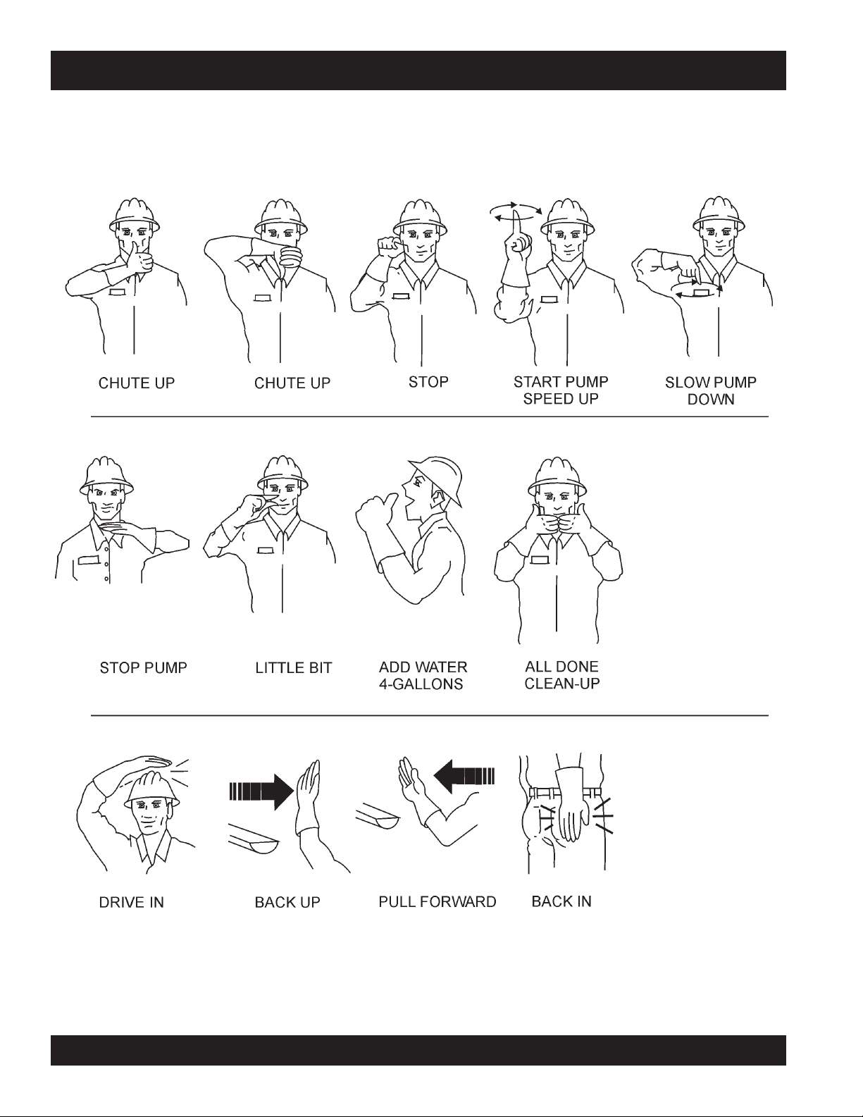
ST-45 PUMP — IMPORTANT HAND SIGNALS
Figure 1 display's the basic hand signals commonly used in concrete pumping operations.
Figure 4 Operation Hand Signals
PAGE 16 — MAYCO ST-45HRM PUMP — OPERATION & PARTS MANUAL — REV. #4 (07/16/04)
Page 17

ST-45 PUMP — GENERAL INFORMATION
Concrete Mix Design
Mix design is most important to achieve maximum pumpability.
Pumpability is affected by, among other factors, the type and
gradation of aggregate used. Natural aggregates make a more
workable mix and pump more readily than crushed aggregates.
A blend of natural and crushed aggregates will produce a
workable mix. The type and gradation of aggregates is equally
important for workability as the size and percentage of coarse
aggregates in the mix.
The term “aggregates” describes all of the solid materials, from
the largest rock to the smallest grain of sand, contained in the
concrete mix.
Concrete mixes with a consistency as dry as one-inch slump
and as wet as ten-inch slump have been pumped; but for
maximum efficiency from the pump, a slump ranging from two to
six inches will produce a more workable mix than one that
contains more or less water.
The principle of concrete pumping is based on self-lubrication.
As it moves through the transfer line, the concrete takes the
shape of a plastic cylinder. It is forced through the transfer line on
a film of mortar that is self-troweled to the service of the transfer
line around its full periphery by the slug of concrete itself.
A slump rating should be used with discretion; it is not always a
real indication of the pumpability of the mix. The concrete may
be workable in the sense that it will readily flow into place, but
the same mix may not respond to pressure. Overly wet mixes
tend to separate. In addition to affecting the strength and quality
of the concrete, the delivery system will not tolerate separation.
Overly dry mixes are similarly unsatisfactory if they lack plasticity
and tend to be crumbly. To be properly pumped, the mix must be
able to continuously coat the inside of the line with a lubricating
seal of mortar.
There are four ways in which this seal can be lost:
1. By pumping excessively wet mixes which do not have
enough cohesion to hold together.
2. By pumping harsh undersanded concrete with poorly graded
aggregates which can jam together when the pressure
becomes too great for the insufficient amount of sand to
hold the aggregates apart.
3. By getting a rock pocket, such as mixer tailings, into the
pump valve. This rock pocket will have an insufficient coating
of mortar and the mix will not be plastic enough to allow the
valve to operate or the mix to move in the line.
4. Through excessive bleeding. If the mix is short or fines, but
the sand is otherwise fairly well graded, bleeding will not
normally create any problems as long as the pump continues
operation. But, if the pump is shut down, bleeding can result
in a loss of lubrication and blocked erratic flow.
The above are bad concrete practices, regardless of how the
mix is to be placed. But, these points do show that special mixes
are not always needed, within limits, for pumping concrete. Good
aggregate gradation is most important to pump concrete the
maximum distance.
The use of admixtures can have a beneficial effect on pumpability.
Most of the dispersing agents will fatten, retard bleeding, and
increase workability. Thus, the average concrete can be pumped
for appreciably longer distances. Air entraining agents will also
improve workability, although they cannot be used as a substitute
for good gradation of the aggregate. Pumping will not appreciably
affect the final air content of the mix. High-early cement tends to
give a more readily pumpable mix with superior water retaining
qualities. However, if delays are likely to occur, extra care must
be exercised due to the faster setting time over regular cement.
The Mayco Model ST-45 will pump a wide variety of concrete
pump mixes. But, there are guidelines that must be followed.
Use this information in conjunction with the
Procedures
Operating
(pages 24-28).
MAYCO ST-45HRM PUMP — OPERATION & PARTS MANUAL — REV. #4 (07/16/04) — PAGE 17
Page 18

ST-45 PUMP — GENERAL INFORMATION
Regional Differences
Concrete is made by mixing locally available rock and sand with
cement and water. For this reason there are great differences in
the pumpability of concrete from one region of the country to
another.
It is impossible to define a specific mix for each region that the
Model ST-45 be will working in. Therefore, the mixes on pages
58-59 will provide a basic guideline for establishing the proper
mix design for your area.
Use this information to specify your requirements to your local
ready-mix batch plant, contractor and civil engineer. It may take
minor adjustments to make a mix pumpable, so you should
explain your needs.
The elements that have to be controlled and consistently
maintained by the batch plant are:
1. The sizing and mix percentage of rocks, gap graded from
the largest down through the smallest sizes.
2. Sand with a sieve analysis that has the proper percentage
of fines, ASTM C33 spec.
3. Sufficient cement to produce the required design strength
of the concrete and provide the lubricating binder to pump
the concrete through the delivery system.
5. The proper amount of water to make a workable slump and
plasticize the mix.
In addition, the Mayco Structural Concrete ST-45 Pump can be
used to pump a large aggregate hard rock as follows:
1. Pea rock (1/2" minus) pump with mixes being as low as 30%
rock and 70% sand. (See page 44, for comments on cleaning
the pump.)
2. Shortening pea rock when used with an air compressor
and nozzle. (See back pages for recommended set-up.)
3. “Mud Jacking”, high pressure grouting.
Use a minimum of:
500 lbs. of cement/cu yd for 2500 p.s.i. concrete after 28
days.
530 lbs. of cement/cu yd for 3000 p.s.i. concrete after 28
days.
600 lbs. of cement/cu yd for 4000 p.s.i. concrete after 28
days.
4. Admixture pump-aid if necessary.
PAGE 18 — MAYCO ST-45HRM PUMP — OPERATION & PARTS MANUAL — REV. #4 (07/16/04)
Page 19
ST-45 PUMP — HOW IT WORKS
The following is a brief explanation of how the concrete cylinders,
hydraulic cylinders, shuttle tube, valves and hopper work in
sequence to pump concrete.
The hydraulic pressure is generated by a variable volume,
pressure compensated, axial piston pump that is driven by a
diesel engine. The rod sides of the drive cylinders are
hydraulically connected together creating a “slave circuit,” which
allows hydraulic oil to transfer from one piston to the other.
The two part cycling sequence is initiated by an electrical signal
generated by two proximity switches located in the drive cylinder.
The proximity switches are normally open, magnetically sensing
the movement of the main drive cylinder. As the drive cylinder
piston head passes the proximity switch, an electrical signal is
sent to the solenoid operated pilot valve which in turn directs
pilot oil to the four valves controlling the drive cylinder and the
shuttle cylinder.
A one-gallon accumulator assists the movement of the shuttle
tube. This circuit assures that the shuttle tube will throw with the
same intensity of each stroke regardless of how fast the main
drive cylinders are cycling.
Figure 5. Pumping Cycle 1
Figure 6. Pumping Cycle 2
In the first cycle, hydraulic pressure is applied to cylinder (B),
causing the hydraulic piston, which is connected to the concrete
piston and piston cup, to discharge concrete into the delivery
line (Figure 5).
As one cylinder is discharging concrete, the hydraulic oil from
the rod side (B) of the drive cylinders is being transferred through
the slave circuit causing the opposite cylinder (A) to move back
on the suction stroke, filling the cylinder with concrete.
The shuttle tube is sequenced to pivot to each concrete cylinder
as the drive cylinders stroke to push concrete. As the second
cycling sequence begins (Figure 6), the shuttle tube pivots to
the opposite cylinder (A). The hydraulic piston passes under the
proximity switch and sends pressure to the piston, causing it to
stroke and discharge concrete into the delivery line. Hydraulic
oil is transfered through the slave circuit to cylinder B, causing it
to start a suction stroke, refilling it with concrete. The pumping
sequence then repeats for the durration of the operation.
MAYCO ST-45HRM PUMP — OPERATION & PARTS MANUAL — REV. #4 (07/16/04) — PAGE 19
Page 20
ST-45 PUMP — PUMP COMPONENTS
Figure 7. Major Pump Components
PAGE 20 — MAYCO ST-45HRM PUMP — OPERATION & PARTS MANUAL — REV. #4 (07/16/04)
Page 21

ST-45 PUMP — PUMP COMPONENTS
Figure 7 illustrates the location of the major components
for the ST-45 Structural Concrete Pump. The function of
each component is described below:
1. Tow Hitch Coupler – Requires a 2-inch ball hitch or a
3-inch pintle. Capable of towing 5,000 lbs.
2. Documentation Box – Contains engine and pump
operation, parts and maintenance information.
3. Hydraulic Oil Tank/Cap– Remove cap to add hydraulic
fluid. Fill with Shell Oil Tellus 68 or Mobil Oil DFE26 if
level is low.
4. Fuel Tank/Cap – Fill with diesel fuel. Fuel tank (cell) holds
approximately 20 gallons (88 liters). DO NOT top off fuel.
Wipe up any spilled fuel immediately
5. Battery – This unit uses a +12 VDC type battery.
use gloves and eye protection when handling the battery.
6. Heat Exchanger – Reduces temperature of the hydraulic
oil. The exchanger draws oil from the hydraulic tank through
a filter and into the heat exchanger before allowing it to
flow into the hydraulic system.
7. Lubrication Box – This box is empty when shipped
from the factory. Please fill with 7 gallons ( 26.5 liters) of
SAE motor oil for first time use. Also check the dual
clean-out point on bottom of lubrication box for a secure
tight fit.
ALWAYS
13. Lubrication Panel – This console allows for the remote
lubrication of components on the pump.
14. Rear Running Lights – ALWAYS check and make sure
both the right and left running lights are functioning correctly
before towing the pump.
15. Accumulator – Stores hydraulic oil under pressure and
releases it to the shuttle cylinder and provides the
required pressure to activate the hydraulic system.
16. Remixer Control Lever – Controls the forward/reverse
motion of the hopper remixer paddles.
17. Manifold – Aluminum block that controls the flow of
hydraulic pressure to the various hydraulic motors and other
components required to control the pump.
18. Hydraulic Pump – This unit incorporates an axial variable
displacement hydraulic piston pump.
19. Throttle Control Knob – This is a variable speed type
control. Turning the throttle lock (CCW) left unlocks the
throttle allowing the throttle control cable to be pulled out to
the desired position. Once the desired throttle position
(speed) has been achieved, turning the throttle lock to the
(CW) right locks it in place. Use the fine tune adjustment
knob to fine tune the engine rpm's.
To place the engine in idle, press the top button inward all
the way..
8. Tires — This trailer uses two ST205-750 x14C type tires.
Tire inflation pressure is the most important factor in tire
life. Pressure should be checked to
operation. DO NOT bleed air from tires when they are hot.
Check inflation pressure weekly during use to insure the
maximum tire life and tread wear.
9. Shuttle Cylinder – Under pressure, the shuttle cylinder
shears concrete passing from the concrete cylinder to
the delivery line durring the cycle phase. The
Accumulator provides the pressure needed to ensure
enough force is provided during cycle.
10. Pump End Jack Stand – Use this jack stand to level
and support the rear end of the pump. NEVER deploy
on un-level ground and always check for firmness of
ground.
11. Hopper/Hood – Lift hood to fill. Concrete from a Redi-Mix
truck is poured into this hopper. The hopper can hold 10 cu.
ft of concrete with optional forward/reverse mixer. NEVER
put hands or any other parts of you body into the hopper.
12. Remixer Motor – Drives the remixer paddles inside
the hopper. The motor direction is controled by the
remixer control lever.
50 psi cold
before
20. Stroke Volume Control Dial – Turns CW/CCW to increase
21. Control Box – Contains the mechanical and electrical
22. Tow End Jack Stand – Use this jack stand to level and
23. Pumping Pressure Gauge – Used to monitor pressure in
24. Accumulator Pressure Gauge– Used to monitor
25. Hydraulic Oil Sight Glass – Use to determine the
26. Hopper Discharge Sleeve – Connect hoses or steel
or decrease the number of strokes per minute of the pump.
components required to run the pump. See page 22 for
components.
support the tow end of the pump.
the concrete cylinders and shuttle tube.
accumulator pressure. Pressure should read at least 1750
psi for correct pump operation.
amount of hydraulic oil remaining in tank. The sight
glass also contains a temperature gauge for monitoring
the temperature of the hydraulic oil.
pipes to the discharge sleeve for pouring concrete.
MAYCO ST-45HRM PUMP — OPERATION & PARTS MANUAL — REV. #4 (07/16/04) — PAGE 21
Page 22
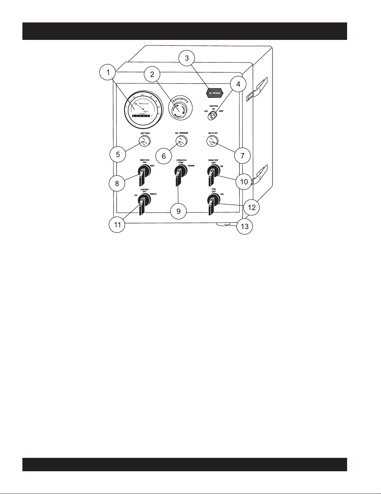
ST-45 PUMP — CONTROL BOX COMPONENTS
Figure 8. Pump Control Box Components
1. Engine Tachometer – Monitors the engine RPM’s and
hours of operation for the engine.
2. Emergency Stop Button – Press emergency stop button
to stop pump in an emergency. Turn knob counter clockwise
to disengage the stop button.
3. Hourmeter – Display's the number of hours the pump has
been in use.
4. Ignition Switch – Insert the ignition key here to start the
engine. Turn the key clockwise to the “ON“ position, then
continue turning clockwise to the “START“ position and
release. To stop the engine turn the key fully counterclockwise to the “STOP“ position.
5. Battery Indicator Lamp– Indicates a low battery charge.
Replace or charge battery.
this lamp is on.
6. Oil Pressure Indicator Lamp– When lit, indicates correct
operational pressure for running the ST-45. NEVER operate
the ST-45 if this lamp is off.
7. Air Filter Indicator Lamp – Indicates the engine air filter
is functioning properly. NEVER operate the ST-45 if this
lamp is off.
NEVER operate the ST-45 when
8. Direction Control Switch– This 2 position switch controls
9. Pump Operation Switch– This 2 position switch controls
10. Pressure Test Switch– Activates a self-diagnostic routine
11. Pumping Control Switch – This 3-position switch controls
12. Cooling Fan Switch – If hydraulic oil temperature exeeds
13. Remote Cable Connector – Insert the remote control input
the direction of flow for any mix in the pump. The
position sets the pumping direction to forward and the
position sets the pumping direction to reverse.
most
the operation of the pumping components and engine. The
center
engine and the
to operate.
which tests the pressure of the pumping system, which can
be read on the Pumping Pressure Gauge.
the pumping of the pump. The
with the remote control unit, the
normal pumping operation, and the
(OFF) prevents pumping.
75° F, set the pump operation switch to engine and turn the
cooling fan switch to the right most position to activate
cooling fan.
cable into this connector.
position allows the operation of the pump and
right most
position allows only the engine
left most
position is for use
center
position is for
right most
center
right
position
PAGE 22 — MAYCO ST-45HRM PUMP — OPERATION & PARTS MANUAL — REV. #4 (07/16/04)
Page 23
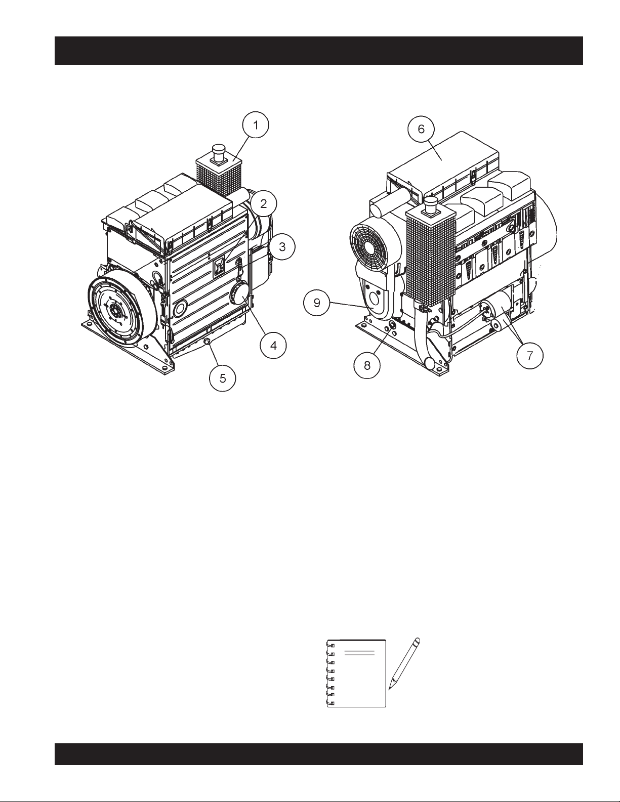
ST-45 PUMP — ENGINE COMPONENTS
Figure 9. Pump Control Box Components
INITIAL SERVICING
The
pump's
lubrication and filled with fuel prior to operation. Refer to the
manufacturers Engine manual for instructions & details of operation
and servicing.
1. Muffler – Used to reduce noise and emissions. NEVER
touch the muffler while it is hot! Serious burns can result.
NEVER operate the engine with the muffler removed.
2. Dip Stick – Remove dipstick to determine if the engine oil
level is low. If low add oil as specified in Table 4, page 30.
3. Speed Control Lever – This lever is connected to the
throttle control which is located on the side of the engine
compartment cover. Use this lever to control engine speed.
4. Oil Filter – Prevents dirt and other debris from entering the
engine. Service the oil filter as recommended in the
maintenance section of this manual.
5. Side Oil Drain Plug – Remove this plug to drain engine
oil from the engine crankcase. For best results drain engine
oil when oil is warm.
engine (Figure 9) must be checked for proper
6. Air Filter/Cover – Prevents dirt and other debris from
7. Starter/Solenoid – This engine uses a 12 VDC , 2.7kW
8. Front Oil Drain Plug – Remove this plug to drain engine
9. V-Belt Cover – Remove this cover to gain access to the V-
entering the fuel system. Release the latches on the side of
the air filter cover to gain access to filter element.
(3.7 HP) starter motor with solenoid.
oil from the engine crankcase. For best results drain engine
oil when oil is warm.
belt. When replacing V-belt , use only recommended type
V-belt.
NOTE
Operating the engine without an air
filter, with a damaged air filter, or a filter
in need of replacement will allow dirt
to enter the engine, causing rapid
engine wear.
MAYCO ST-45HRM PUMP — OPERATION & PARTS MANUAL — REV. #4 (07/16/04) — PAGE 23
Page 24
ST-45 PUMP — OPERATING PROCEDURES
OPERATING SUGGESTIONS
1. A well-planned location of the pump and routing of the hose
before starting a pour may save subsequent moves throughout the job.
2. Before concrete is discharged into the hopper, it is suggested
that 3 to 4 gallons of water be sprayed into the hopper,
followed by approximately 5 gallons of a creamy cement and
water slurry (1/2 bag of cement to 5 gallons of water). This
procedure lubricates the hose and prevents separation and
blockages in the hose.
Getting the concrete to flow through
NOTE
CAUTION
Inspect the lines at all times to prevent the above conditions
3. It is important that once the slurry procedure is completed,
and you have started concrete flowing through the hose, do
not stop the pour until all the slurry is pumped out and the
concrete has reached the end of the hose. The only time to
stop the pump at the start is if a blockage occurs.
4. When the pump is stopped for any reason during a pour; e.g.,
moving hose, waiting for redi-mix truck, the following suggestions are offered:
the hose at the start of the pumping
cycle can be one of the most critical
operations of the pour. (
operate the throttle when starting,
NOT REMOTELY)
If hoses or lines are
or if the lines are
during the pumping cycle, the pump
pressure could straighten out the kink or
force out the blockage. This rapid surge of
material could cause the lines to
move
in a manner that could cause injury to
personnel.
blocked
kinked
when starting up or
Manually
for any reason,
whip
or
C. If it is necessary to wait 10 minutes or more for another
D. When pumping stiff mixes and there is waiting time
E. When the pumping job requires a stiffer mix, the
F. Hose sizing is very important: We strongly recom-
5. Following the pump operation, proper wash out of all materials or “build-up” within the pump manifold and hoses will
prevent problems when starting the next job.
6. A thorough inspection of the drive components and greasing
of all bearings after each job will ensure adequate lubrication
and service to the pump which is normally operating in wet,
gritty conditions.
load of concrete, it is wise to start the pump and pump
6 or 8 strokes every 5 minutes to prevent setting of the
mix in the system. If waiting time is excessive, it would
be wise to wash out the pump and hoses and start over
when the new truck arrives.
between redi-mix trucks, it is advisable to add some
water to the last hopper of material and “hand mix” to
ensure an easier start with the following load.
following method is suggested for starting: Take a
water hose with a nozzle on it and apply water with a
fine spray to the concrete as it comes down the redimix chute into the pump hopper after the slurry
procedure is completed and you are ready to start
pumping.
Using this procedure will make it easier to pump
through the clean hose. Note: Once the concrete has
reached the end of the hose, do not apply any more
water in this manner as this procedure is used for
starting only.
mend on harsh mixes, vertical pushes, stiff concrete,
shotcrete, long pushes, that a 2 -1/2” line be used as
far as possible. The advantages of using the 2 -1/2” line
are improved pumpability, less pumping pressure and
less wear on the pump.
A. Leave the hopper full of concrete at the time of
shutdown. It is important not to let the
wash too much water into the hopper, as this could
cause separation of the concrete in the hopper.
B. If the
shutdown
off the engine so the vibration does not separate the
mix in the hopper which can cause a blockage in the
manifold when the pump is started.
PAGE 24 — MAYCO ST-45HRM PUMP — OPERATION & PARTS MANUAL — REV. #4 (07/16/04)
period exceeds 2 to 3 minutes, turn
redi-mix
driver
NOTE
Over-greasing any
your Mayco pump will not damage
the bearing.
bearing
on
Page 25

ST-45 PUMP — OPERATING PROCEDURES
WARNING
Common sense tells us that if you drive a
truck into a brick wall, something is going to
be damaged. The same holds true with your
concrete pump. If you repeatedly pull the
throttle all the way out and try to force your
pump to push through
separation of material in the hose or manifold, you will soon
have breakdowns and costly repairs which are not covered
under warranty. If a blockage occurs, find where it is and clear it
before further pumping. DO NOT increase the engine speed to
clear the blockage. Increasing the engine speed will only
compound the problem.
blockages
due to
B. MBVR – air entraining, acts as a lubricant.
C. Calcium Chloride – commonly referred to as C.C., is
D. Super Plasticizers – acts as an accelerator. The
E. Red Label – acts as a water retarder and an accelerator.
WARNING
It will be necessary at times to move your
pump from one job site location to another.
Before moving the pump, make sure to pump
the remaining concrete out of the hopper.
Moving the pump with a
concrete can cause severe damage or
breakage of the axle and axle springs, excess
strain and pressure on the hub and bearing assembly.
Pumping Tips
full hopper
of
F. Fly Ash – is used to help increase the strength of the
NOTE
used as an accelerator. When pumping a load with
calcium chloride, it is recommended that you wash out
if the waiting time between delivery trucks becomes too
long.
concrete will look very wet after the super plasticizer is
added, but will begin to set up very fast. Wash out
immediately if you do not have a truck waiting. Super
plasticizers are used mainly on commercial jobs.
Red label will be used mainly on commercial jobs.
concrete and decrease the cement content per yard.
This is one of the most common admixtures used.
All admixtures will be shown on the
redi-mix concrete ticket. Before starting the pumping job, ask the driver of
the redi-mix truck to see the concrete
ticket and note the admixtures that
exist and take the proper action.
The effects of heat and excessive time on concrete:
7. Hot concrete, commonly referred to as a hot load, is concrete
that has been in the redi-mix truck in excess of 2 to 3 hours.
On a hot day, this amount of time is even less. A brief
explanation of why heat and time affect concrete:
8. Concrete starts setting by drying up through a chemical
reaction. The catalyst to this reaction is heat. When pumping
a hot load, it is important to remember that when you have to
stop pumping for any reason, add water to the concrete in the
hopper and hand mix and move concrete in the hose every
5 minutes. If the shut down time becomes too long, wash out
immediately.
Admixtures:
9. Remixtures that are designed into the concrete mix by the
redi-mix company or an architectural engineering company.
This section lists common admixtures and a brief explanation of their functions:
A. Pozzolith 300 – or the equivalent acts as a water
retarder and a lubricant. On a lean mix, long pushes, stiff
mixes, and vertical pushes, Pozzolith 300R helps
pumpability.
10. When pumping long distance or pumping stiff mixes, you can
expect a drop in volume compared to shorter lines and wetter
mixes due to the change in valve efficiency or cavitation.
11. Leaking manifold seals or hose coupling gaskets which leak
water can cause separation and subsequent jamming at that
point.
Priming the Pump and Delivery System with Slurry
12. It is CRITICAL to the successful operation of a concrete
pump that the manifold and all delivery hose, pipe and
elbows are coated with a film of lubrication BEFORE you
attempt to pump concrete. Failure to properly prepare the
pump and system will result in a “dry pack” of concrete,
blocking the shuttle valve tube or delivery line.
A. With the entire delivery system connected to the pump.
B. There are several things you can use for the prime. A
Except for the first hose. Pour 5 gallons of water into the
second hose and push in your clean out ball and
reconnect. This will help hold back the prime.
few examples are Cement and lime at a 50/50 mixture,
slick pac, bentonite clay.
MAYCO ST-45HRM PUMP — OPERATION & PARTS MANUAL — REV. #4 (07/16/04) — PAGE 25
Page 26
ST-45 PUMP — OPERATING PROCEDURES
C. Mix the prime to the consistency of a smooth batter.
D. Position the first ready-mix truck at the hopper. Check
the concrete. DO NOT discharge concrete into hopper
at this time.
The bentonite is not compatible with
NOTE
concrete. DO NOT pump it into the
forms discharge it out of the formed
area.
16. The shuttle tube is plugged if volume at the discharge end of
the hose stops, the hose is soft and the hydraulic oil pressure
gauge reads 3000 psi or more.
To clear a plug in the shuttle tube, great care must be taken
as a dangerous condition will exist from pressure build-up
inside the shuttle tube. (With the shuttle valve, the concrete
can be pumped in reverse.) Use the following prodedures
to clear the shuttle tubes.
WARNING
E. Pour approximately two 5 gallon buckets of prime into
the first hose and connect it to the pump.
F. With the pump in FORWARD at 25-30 strokes per
minute, slowly discharge the concrete from the readymix truck into the hopper and completely fill it. Keep the
pump running continuously until concrete is discharging
at the end of the delivery system. If the pump is stopped
during this procedure, a blockage may occur.
G. If it is necessary to replace or add a section of delivery
system, after the initial lubrication procedure, wet the
inside area of the hose, pipe or elbow with 5 gallons of
water per 25 foot length, before adding it to the system.
Clearing Concrete Blockage
13. Damaged hoses with internal restrictions can cause blockages.
14. If a blockage occurs in a hose,
the point of trouble. The hose will be soft immediately past the
blockage. If this happens at the start, disconnect the hose at
the first coupling past the blockage.
walk the hose
until you find
“Reverse” Pumping Procedure
A. Switch the pump into
B. Remix the concrete in the hopper.
C. Switch the pump into
If concrete still does not move, proceed to the Shuttle Tube
Inspection Procedure.
Shuttle Tube Inspection Procedure
A. Stop the pump. Switch off the engine.
B The senior or most experienced operator must warn all
DO NOT open any of the
delivery system joint clamps.
reverse
medium-slow (approx. 12 strokes per min.) try to pull
the “pack” back into the hopper with 5 or 6 reverse
strokes.
forward
“Reversing” procedure three times.
others to stand at least 20 feet away from the machine
and turn their heads to face away from the pump.
. With pump speed at a
. If it is still plugged, repeat
15. Elevate the hose at that point with the blockage area hanging
down. Using a hammer, you can pound the down-stream
edge of the packed area until it is free to flow. Shake all of the
sand and gravel out to the end of the hose. Before reconnecting the hose, start the pump and run a small amount of
concrete out to the end of the hose. This will assure that all
of the separation is out of the hose.
CAUTION
Use extreme care! The hose line is under
pressure
PAGE 26 — MAYCO ST-45HRM PUMP — OPERATION & PARTS MANUAL — REV. #4 (07/16/04)
and can cause serious injury.
CAUTION
C. The operator will position themself beside the reducing
Saftey glasses MUST be worn at all times
when operating the ST-45. Failure to follow saftey guidlines can result in serious
injury.
elbow at the pump outlet. Wearing
slip the end of a pry bar (24" length of reinforcing steel
rod) under the latch of the hose clamp and flip it up.
safety glasses
,
Page 27

ST-45 PUMP — OPERATING PROCEDURES
D. Carefully knock the end of the hose away from the
reducer.
E. Chip the concrete out of the reducer with the pry bar.
F. Remove the reducer. From the discharge end,
chip the concrete out of the shuttle tube with the pry-bar.
If concrete cannot be loosened from the outlet of the
shuttle tube, remove the clean-out plug on the bottom
of the hopper to discharge the concrete.
G. The senior operator may then remove the inspection
cover plate from the shuttle tube by using a long
extension wrench and the 24" pry bar.
If, for any reason, the mix should set up in the system, the
following procedure (
WARNING
Make sure the accumulator pressure gauge
reads ZERO psi. prior to performing any
maitinance or inspection.
H. Chip the blockage out with the pry-bar.
I. Flush the shuttle tube with water.
J. Replace and seal the inspection cover plate on the
shuttle tube.
K. Before resuming operation of the pump, perform the
“Reverse” Pumping Procedure to relieve pressure on
the shuttle tubes.
17. If it is necessary to wait 1/2 hour or more for another load
of concrete, and to prevent setting of the mix in the system,
it is advisable to consider the following factors
A through D
(
A. How old is the concrete?
B. Is there an accelerator, calcium chloride, red label, etc.,
in the concrete?
C. The temperature of the day, 80, 90, degrees?
D. How much system you have out and how stiff was the mix
you were pumping?
) affecting the concrete :
18. Down-Hill Pumping – can be difficult on some jobs. The
slurry procedure would be the same as explained on the
pages titled Operating Suggestions. It is suggested that a
sponge 2”x 4”x 6” be placed in the hose before the start of
pumping. Wet the sponge before placing it in the hose.
The reason for using the wet sponge is to keep the slurry from
running too far ahead of the concrete and so reducing the
possibility of separation. When the pump is stopped, the
material can flow slowly down, due to gravity, and cause the
hose to collapse.
When pumping is resumed, you can expect blockage at the
point of hose collapse. To prevent this from happening, the
hose can be “kinked off” at the discharge end when the pump
is stopped to prevent the gravity flow of the material in the
hose.
The use of stiffer mixes when pumping down-hill will decrease gravity flow of the material in the hose and will assure
a smoother operation between the cam roller bearing and
cam plate. As with any job, make sure that the hose and the
couplings are in good workable shape.
E through H
E. Disconnect the hose from the pump and wash the pump
out immediately.
F. Reconnect the hose and fill the hopper with water.
G. Reconnect the hose and fill the hopper with water. DO
NOT try to push all the concrete out of all of the hose
lines at one time.
For example: If you had 200 ft. of system out, you would
disconnect each hose. Clean it out by pushing water
through the first hose off the pump, then continue
progressing through all the hoses, until all the system
is clean.
H. If waiting time is excessive, it would be wise to wash out
the pump and hoses and start over when the new truck
arrives. This can be avoided by being observant to the
pump and system, also taking into consideration the
above factors (E through H) affecting the mix.
) is suggested:
NOTE
When disconnecting hoses, use
EXTREME CAUTION! The hose is
pressure!
under
MAYCO ST-45HRM PUMP — OPERATION & PARTS MANUAL — REV. #4 (07/16/04) — PAGE 27
19. Vertical Pumping – When pumping vertically up the side of
a building, above 40 feet, we would recommend the installation of
to support the pipe. Ninety degree, long radius pipe sweeps
should be installed at the top and bottom of the steel line.
steel pipe
securely fastened at intervals as necessary
Page 28

ST-45 PUMP — OPERATING PROCEDURES
Use a 25 ft. hose, or short section, off the pump; and for the
balance of the horizontal distance to the vertical line, use
steel pipe. This type of installation has been satisfactory on
many jobs being pumped in excess of 100 feet high. Line
pressures are always less using steel pipe as compared to
hose.
When pumping vertically, using
not to go higher than 50 feet with hose. The hose should be
tied off at intervals of 10 feet, if possible. Special attention
should be given when tieing the hose off at the top as the hose
will have a tendency to stretch when filled with concrete. This
will increase the possibility of a blockage at the point where
the hose is tied off. To avoid this, a long radius of 90 degree
elbow is recommended. The suggested place to tie off is on
the hose, under the clamp.
NOTE
all hose
It is strongly recommended that
steel pipe be used on all vertical
, it is recommended
entire drive system and valving under simulated full load
conditions. The pump owner can do the same by making an
adapter to couple to the end of the discharge cone: e.g., the
use of a standard 2" pipe cap with a 3/8" drilled hole in the
center, screwed on to the end of hinged cone or reducer at
the pump.
Fill hopper with water after making sure that all sand and rock
have been removed from manifold. Operate pump at full
throttle and the 3/8" diameter hole restriction will create
sufficient back pressure to make thorough inspection of all
moving parts.
pumping for safety and convenience.
20. Pulsation – A slight pulsation of the hose will always be
noticeable near the pump. Excessive pulsation of the hose
near the pump is normally due to higher than average line
pressures caused by stiff, harsh mixes, or extremely long
pumping distances.
The use of 2 -1/2” I.D. hose in these extreme cases reduces
line pressures or the addition of slight amounts of water to the
mix, if permissible, will permit easier pumping. The use of
certain pumping admixtures may help.
If excessive pulsation exists in the hose, it is advisable to use
burlap or some means of wear protection under the hose at
points where the hose may wear through the outer cover; e.g.
over forms, steel or sharp curbs.
21. Snap-Joint – When using Snap-Joint couplings with gaskets to join hose, see that they are washed clean after each
job. Keeping the hose ends clean (heavy duty) is very important for the best job setup. A thin coat of grease on the rubber
gasket or dipping both coupling and gasket in water before
coupling the hose will make for easier installation.
22. New Pumps – All new pumps are ‘water pressure tested” at
the factory This procedure permits a thorough inspection of
PAGE 28 — MAYCO ST-45HRM PUMP — OPERATION & PARTS MANUAL — REV. #4 (07/16/04)
Page 29
CAUTIONCAUTION
CAUTION
CAUTIONCAUTION
NEVER operate the pump
in a confined area or
enclosed area structure
that does not provide
free flow of air
ample
.
ST-45 PUMP — INSPECTION
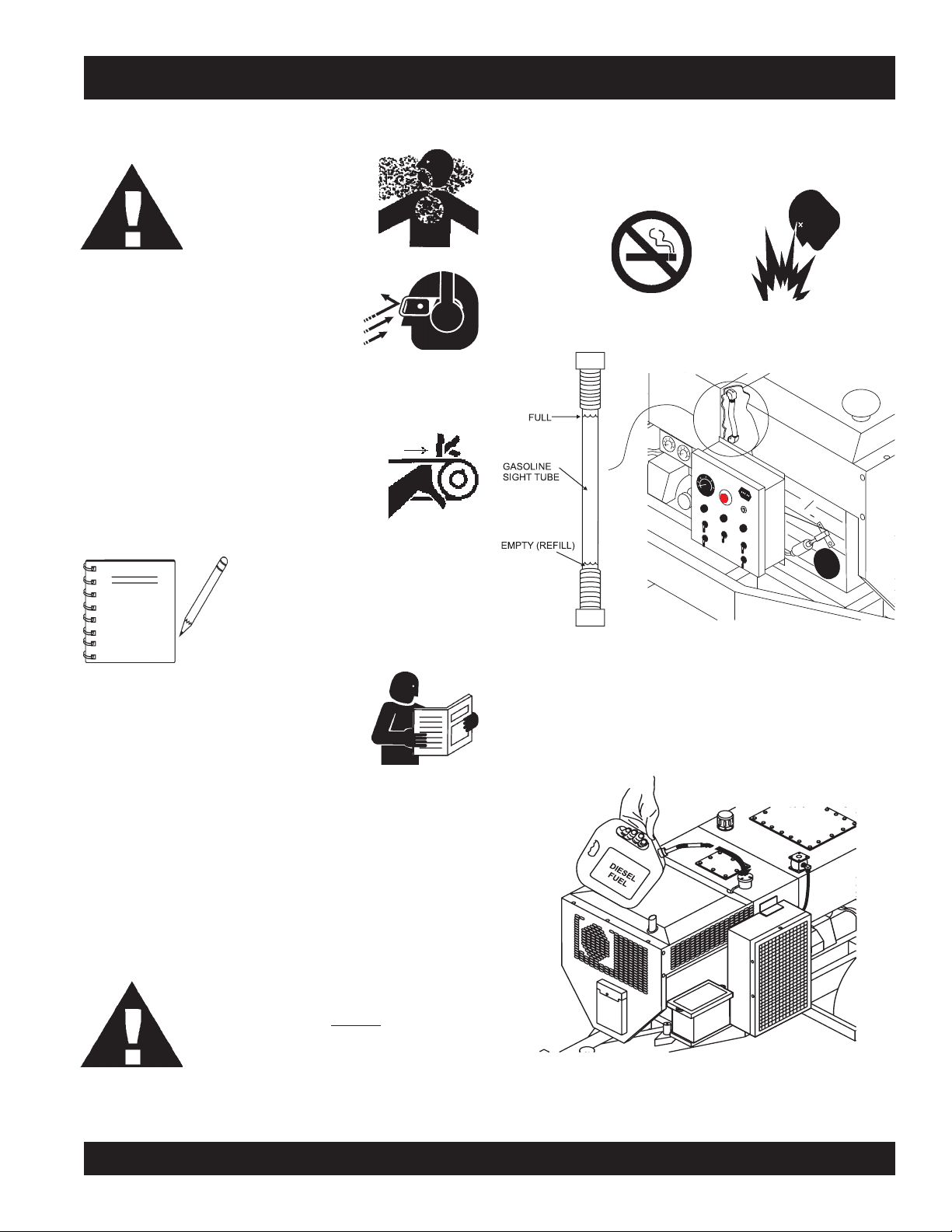
FUEL CHECK
5. Read the fuel sight tube (Figure 10) on top of the fuel tank
to determine if the pump's engine fuel is low .
ALWAYS wear approved
protection before operating the pump .
NEVER place hands or feet inside the
while the engine is running. ALWAYS shut-down the engine
before performing any kind of maintenance service on the pump.
NEVER operate the pumps's engine with the
engine hood removed. The possibility exists of
hands, long hair
entangled with the V-belt, causing injury and
bodily harm.
NOTE
Before Starting
1. Read safety instructions at the beginning of manual.
eye
and
hearing
hopper
, and
clothing
See Figures 5 & 6 on pages 20-22 for
the location of any control or
component referenced in this section.
becoming
. ALWAYS make
Figure 10. Fuel Sight Tube
6. If fuel is low, remove fuel filler cap and fill with
(Figure 11).
fuel
#2 diesel
2. Clean the
the engine cooling air inlet, and air filter.
3. Check the
air filter with a new one as required.
4. Check fastening nuts and bolts for tightness.
entire pump
air filter
, removing dirt and dust, par ticularly
for dirt and dust. If air filter is dirty, replace
CAUTION:
Handle fuel safely. Diesel fuel is highly
flammable
mishandled. DO NOT
DO NOT attempt to refuel mixer if the engine is
hot or running. ALWAYS
before refueling.
MAYCO ST-45HRM PUMP — OPERATION & PARTS MANUAL — REV. #4 (07/16/04) — PAGE 29
and can be dangerous if
smoke
while refueling.
allow engine to
cool
Figure 11. Adding Diesel Fuel
Page 30

ST-45 PUMP — INSPECTION
ENGINE OIL CHECK
7. Remove the engine oil dipstick from its holder (Figure 12).
Figure 12. Engine Oil Dipstick
8. Make sure pump/engine is placed on level ground.
12 The oil listed in Table 47 is recommended to ensure
better engine performance. Use class CD or higher grade
motor oil.
9. Pull the engine oil dipstick (Figure 13) from its holder.
Figure 13. Engine Oil Dipstick
Hydraulic Oil
13. Determine if the hydraulic oil level is low by observing the
level of the oil in the Hydraulic Oil Sight Glass (Figure 14).
Figure 14. Hydraulic Oil Sight Glass
10. Verify that oil level (Figure 13) is maintained between
the two notches on the dipstick.
11. If the pump's engine oil is low, fill engine crankcase
with lubricating oil through filler hole, but DO NOT overfill.
PAGE 30 — MAYCO ST-45HRM PUMP — OPERATION & PARTS MANUAL — REV. #4 (07/16/04)
Page 31

ST-45 PUMP — INSPECTION
14. If the hydraulic oil level is low, remove the cap just above the
oil level sight glass (Figure 15) and add the correct amount
of hydraulic oil to bring the hydraulic oil level to a normal
safe operating level. (Use Shell oil Tellus 68 or Mobil oil
DFE26).
16. Remove the
pull
then
(Figure 17).
17. Position both rear stabilizers stands on firm (not loose)
level
18. Align the hole on the stabilizer stand with the hole on the
frame body and
19. Insert the cotter pin into handle tee bolt eye to lock the
stabilizer stand.
cotter pin
the handle tee to release the stabilizer stand
ground (Figure 18).
from the handle tee bolt eye, and
insert
handle tee bolt.
Figure 15. Hydraulic Oil Filler Hole
REAR STABILIZER STAND
To reduce excessive vibration and rocking of the ST-45 Concrete
Pump, set the rear stabilizers as follows:
15. Locate both the left and right rear stabilizer stands
(Figure 16).
Figure 17. Rear Stablizer Stand
Figure 18. Rear Stablizer Stand Deployment
Figure 16. Locatiing Rear Stabilizer Stands
MAYCO ST-45HRM PUMP — OPERATION & PARTS MANUAL — REV. #4 (07/16/04) — PAGE 31
Page 32

ST-45 PUMP — INITIAL START-UP PROCEDURE
Starting
CAUTION :
DO NOT attempt to operate this concrete
pump until the Safety, General Information
and Inspection sections have been read
and understood.
EMERGENCY STOP SWITCH
1. Locate the Emergency Stop Switch (Figure 19) on the
Hydraulic Pump Control Box. Use this switch in the event of
a emergency.
IGNITION SWITCH
3. To start the engine, insert the key (Figure 20) into the ignition
switch and turn the key to the ON position.
4. Observe that the
indicator lights are “ON” (Figure 21).
Figure 20. Ignition Switch
Batter, Air Filter
BATTERY
OIL
PRESSURE
and
Oil Pressure
AIR FILTER
status
Figure 19. Emergency Stop Switch
2. Turn the Emergency Stop switch counter-clockwise (open).
This will allow the engine to start.
If the Emergency Stop switch is in the
NOTE
NOTE
“CLOSED” position (stop), engine will
not start. To start the engine, make
sure the Emergency Stop switch is in
the “OPEN” position (fully extended).
Place all switches on the Hydraulic
Control Box in the ”OFF” (up position).
Figure 21. Status Indicator Lights
A. Turn the key to the “START“ position and listen for the
engine to start.
B. In warm weather let engine warm-up for 5 minutes. In
cold weather let engine warm-up for 10 minutes.
C. The
NOTE
Air Filter, Oil Pressure
(Figure 21) should all be “OFF”.
The battery indicator light may remain
on if the engine is idling, or on some
models of the ST-45. Increasing the
engine RPM’s slightly should correct
the problem.
and
Battery
indicator lights
CAUTION :
If any of the status indicator lights referenced
in the ignition section (step 4) remain “ON”,
turn off the engine and correct the problem.
DO NOT continue to run the equipment.
PAGE 32 — MAYCO ST-45HRM PUMP — OPERATION & PARTS MANUAL — REV. #4 (07/16/04)
Page 33

ST-45 PUMP — INITIAL START-UP PROCEDURE
PUSH-IN, THEN PULL
TO SET THROTTLE
(RPM’s)
PUSH ALL THE WAY IN
TO IDLE ENGINE
CONTROL SWITCH
5. Turn the Pump Control switch (Figure 22)
to the “ON” position, a
thumping
sound
(cylinder stroke) should be heard. The
thumping sound represents the number
of strokes per minute (volume) of the
pump.
Figure 22. Pump Control Switch
6. Turn the Volume Control (Figure 23),
lock nut
counterclockwise (CCW) to release the volume control
knob.
8. While monitoring the tachometer,
(Figure 25) use the Engine
Throttle Control to set the engine
speed to 1500 RPM by following
steps 8A-8C.
Figure 25. Engine
Tachometer
A. Unlock the throttle cable. To unlock the throttle cable, turn
the inner most knob counter clockwise (Figure 26.)
UNLOCKING
THROTTLE
UNLOCK
ADJUSTMENT
KNOB (COARSE)
(PUSH/PULL)
LOCK
THROTTLE
ADJUSTMENT
KNOB (FINE)
(TURN CW/CCW)
KNOB
Figure 23. Volume Control
6. Use the volume control, to set the
pump volume to approximately 10
strokes per minute. Turning the
volume control clockwise (CW)
decrease
will
pump volume,and
counterclockwise (CCW) will
increase pump
Figure 24. Hydraulic Oil Temperature Gauge
volume.
7. Let the pump cycle until the hydraulic oil temperature
(Figure 24) is approximately 50 to 60 degrees fahrenheit.
NOTE
Use a wristwatch or stop watch to
determine the number of pump
strokes within 1 minute.
Figure 26. Throttle Control Knob (Un-locking)
B. Push the outermost button, Figure 27 (coarse adjust-
ment) inward, then pull outward until engine RPM
reaches desired speed.
C. Turn the unlocking knob (figure 26) clockwise to lock
engine RPM in place.
Figure 27. Throttle Control Knob (RPM Adjust)
9. Turn the Control Off switch (Figure 10) to the “OFF“ position.
MAYCO ST-45HRM PUMP — OPERATION & PARTS MANUAL — REV. #4 (07/16/04) — PAGE 33
Page 34

ST-45 PUMP — INITIAL START-UP PROCEDURE
ENGINE SPEED
10. Turn the Operation Pump/Engine switch
to the “ENGINE” position (Figure 28).
Figure 28. Operation Pump Engine
Switch
NOTE
11. While monitoring the
tachometer (Figure 25), use the
Engine Throttle Control to set
the engine speed to 2550 RPM
(maximum speed) using steps
8A-8C
12. The Accumulator Pressure
Gauge (Figure 29) should read
approximately 1750 pounds per
square inch (psi).
The pump should not be cycling at this
time. Only the ENGINE should be
running.
13. Make sure the Operation Pump/Engine
switch is in the “ENGINE“ position
(Figure 28), and that only the engine is
running.
14. Turn the fan switch (Figure 30) to the “ON“
position and listen for fan to start.
Figure 30. Fan On/Off Switch
15. Turn the fan switch to the “OFF“ position and listen for fan
to stop. If machine exceeds 170°F or to cool the machine
down, turn the operation switch (Figure 28) back to the
“ENGINE“ position. Run engine at high RPM with cooling
fan on for 10 to 15 minutes.
PRESSURE TEST
16. The Pressure Test switch (Figure 31) is a
self-diagnostic test switch, that when
activated will test the pressure of the system.
This switch will be discussed in the
maintenance and troubleshooting section
of this manual.
Figure 31. Pressure Test On/Off Switch
Figure 29. Accumulator Pressure Gauge
HOPPER REMIXER CONTROL
COOLING FAN
This section is intended to make sure the fan is working properly.
Under normal conditions the fan should be turned on when the
hydraulic oil temperature begins to approach 75 degrees
fahrenheit.
A. Located to the left of the Hydraulic Temperature gauge is
the Hopper Remixer Control lever (Figure 32).
B. Turn the Operation Pump/Engine switch to the “ENGINE“
position (only the engine should be running).
CAUTION
If the hydraulic oil temperature exceeds 170
degrees fahrenheit, shut down the pump.
DO NOT continue to operate the pump.
Failure to shut down the pump will result in
severe damage to the pump.
Figure 32. Hopper Remixer Control Lever
PAGE 34 — MAYCO ST-45HRM PUMP — OPERATION & PARTS MANUAL — REV. #4 (07/16/04)
Page 35

ST-45 PUMP — INITIAL START-UP PROCEDURE
C. Push the Hopper Remixer Control lever “DOWNWARD“
(Figure 31) and observe that the blades (Figure 33) inside
the hopper are turning in a clockwise direction (forward).
Figure 35. Handheld Remote Cable Unit
Figure 33. Hopper Remixer Blades (Rotation)
CYLINDER LUBRICATION BOX
WARNING
D. Push the Hopper Remixer Control lever “UPWARD“ (Figure
32) and observe that the blades (Figure 33) inside the
hopper are turning in a counter-clockwise direction
(reverse).
OPTIONAL RADIO REMOTE CONTROL
14. The MAYCO ST-45 Concrete Pump has a remote control
feature that allows the pump to be remotely controlled. If
desired, the pump can be operated via a receiver/transmitter
method (Figure 34) or a hardwire method, which utilizes a
25-ft. extension cable. The manual remote cord (Figure 35)
should be installed under the main control box. Contact
your MAYCO representative for further information.
15. As the rubber piston cups naturally wear, fine cement
Before checking lubricaton level, stop the
engine and remove the engine starter key.
We recommend using soluble type oil (water
& oil mixture). The oil level should be
checked every day prior to pumping. The oil
level should be maintained at a height of 5
inches or about ½ the concrete cylinder
height.
Important Notice! During freezing
NOTE
particles will accumulate in the box. Once the concrete paste
reaches a height of about ½ inch from the bottom. The box
should be drained and cleaned. To clean, remove the drain
plug located at the bottom of the box.
temperature after pumping, completely
drain the water box and cover the
hopper. Frozen liquid will restrict the
piston travel and cause severe
damage to the pump.
Figure 34. Handheld Receiver/Transmitter
MAYCO ST-45HRM PUMP — OPERATION & PARTS MANUAL — REV. #4 (07/16/04) — PAGE 35
Once the box is drained, start the engine and stroke the
cylinder (keep hands out of box) ten to fifteen times. While
stroking, spray water inside of the box to thoroughly clean
out all contamination. When the box is clean, replace drain
plug, add new lubrication and install the top cover.
Page 36

ST-45 PUMP — TOWING GUIDELINES
Towing Safety Precautions
CAUTION
■
Check with your county or state safety
towing regulations department before
towing your
To reduce the possibility of an accident while transporting the
pump on public roads, always make sure that the trailer and
the towing vehicle are in good operating condition and both
units are mechanically sound.
The following list of suggestions should be used when towing
the pump:
■
Make sure that the hitch and coupling of the towing vehicle
are rated equal to, or greater than the trailer "gross vehicle
weight rating" (GVWR).
■
ALWAYS inspect the hitch and coupling for wear. NEVER
tow the light tower's trailer with defective hitches, couplings,
chains etc.
■
CHECK the tire air pressure on both the towing vehicle and
the trailer. Also check the tire tread wear on both vehicles.
■
ALWAYS make sure the trailer section of the pump is
equipped with a "Safety Chain".
■
ALWAYS attach trailer's safety chain to frame of towing
vehicle.
■
ALWAYS make sure that the vehicle and trailer directional,
backup, brake, and trailer lights are connected properly and
are working properly.
■
Remember in most cases the maximum speed unless
otherwise posted for highway towing is 45 MPH, however
before towing your pump, check your local state, and county
vehicle towing requirements. Recommended off-road towing
is not to exceed 10 MPH or less depending on type of terrain.
■
Place
chocked blocks
while parked.
■
Depending on soil conditions and location it may be
necessary to place
bumper to prevent
■
Inflate tires to correct pressure, inspect tires for cuts, and
excessive wear. See Table 5 (Tire Wear Troubleshooting).
underneath wheel to prevent
support blocks
tipping
concrete pump
underneath the trailer's
, while parked.
.
rolling,
■
Check wheel mounting lug nuts with a torque wrench.
Torque wheel lug nuts as described in the "
Requirements
■
Make sure brakes are synchronized and functioning properly.
■
Check tightness of suspension hardware (nuts and bolts).
■
Avoid sudden stops and starts. This can cause skidding, or
jackknifing. Smooth, gradual starts and stops will improve
gas milage.
■
Avoid sharp turns to prevent rolling.
■
Retract wheel stand when transporting.
■
DO NOT transport pump with fuel in the fuel tank.
CAUTION
Pump Trailer Vehicle Connection
1. Check the vehicle hitch ball, and trailer coupler for signs of
wear or damage. Replace any parts that are worn or
damaged before towing.
2. Use only the 2-inch ball diameter with a towing capability of
5,000 lbs. (2,268 kg) as indicated on the trailer's coupler.
Use of any other ball diameter will create an extremely
dangerous condition which can result in separation of the
coupler and ball or ball failure.
3. Be sure the coupler is secured to the hitch ball and the lock
lever is down (locked).
4. Attach safety chains as shown in Figure 36. Remember to
cross
5. After towing for about 50 miles recheck the entire towing
system for tightness.
Recommended Maintenance
1. Smear ball socket and clamp face with chassis grease.
Periodically oil pivot points and were surfaces of coupler
with SAE 30 W motor oil.
2. When parking or storing the concrete pump, keep the coupler
off the ground so dirt and other debris will not build up in the
ball socket.
Lug Nut Torque
", Table 7.
If the trailer coupler is deformed replace
entire coupler. NEVER tow the pump with
a defective trailer coupler. There exist the
possibility of the trailer separating from the
towing vehicle.
the safety chains.
PAGE 36 — MAYCO ST-45HRM PUMP — OPERATION & PARTS MANUAL — REV. #4 (07/16/04)
Page 37

ST-45 PUMP — TOWING GUIDELINES
Figure 36 shown below illustrates the typical towing
application that should be used when towing the pump.
Figure 36. Towing Applications
MAYCO ST-45HRM PUMP — OPERATION & PARTS MANUAL — REV. #4 (07/16/04) — PAGE 37
Page 38

ST-45 PUMP — TRAILER SAFETY GUIDELINES
Trailer Safety Precautions
CAUTION
ALWAYS make sure that the trailer is in good
operating condition. Check the tires for
proper inflation and wear. Also check the
wheel lug nuts for proper tightness.
This section is intended to provide the user with trailer service
and maintenance information. Remember periodic inspection of
the trailer will ensure safe towing of the equipment and will
prevent damage to the equipment and personal injury.
It is the purpose of this section to cover the major maintenance
components of the trailer. The following trailer components will
be discussed in this section:
■
Tires
■
Lug Nut Torquing
■
Suspension
■
Electrical
8. Wheel Hub – The wheel hub is connected to the trailer's axle.
9. Tire Rim – Tires are mounted on a tire rim. The tire rim must
match the size of the tire.
10. Lug Nuts – Used to secure the wheel to the wheel hub.
Always use a torque wrench to tighten down the lug nuts. See
Table 7and Figure 38 for lug nut tightening and sequence.
11. Axle – This trailer employes a torsion bar type suspension,
which can support 3,500 lbs.
12. Electrical – Electrical connectors (looms) are provided with
the trailer so that brake lights and turn signal lights can be
connected to the towing vehicle. See Figure 43 for proper
wiring connections.
The following list defines the major trailer components:
1. Frame Length – This measurement is from the ball hitch to
the rear bumper (reflector).
3. Frame Width – This measurement is from fender to fender.
4. Jack Stand – Trailer support device with maximum pound
requirement from the tongue of the trailer.
5. Coupler – Type of hitch used on the trailer for towing. This unit
employes a 2" ball.
6. Tires Size – Indicates the diameter of the tire in inches (10,
12, 13, 14, etc. ), and the width in millimeters (175, 185, 205
etc.). The tire diameter must match the diameter of the tire rim.
This unit employes 7.35" X 14" tires.
7. Tires Ply – The tire ply (layers) number is rated in letters; 2ply, 4-ply, 6-ply, 8-ply, 10-ply etc. This unit employes 4-ply
tires.
PAGE 38 — MAYCO ST-45HRM PUMP — OPERATION & PARTS MANUAL — REV. #4 (07/16/04)
Page 39

ST-45 PUMP — TRAILER SAFETY GUIDELINES
Tires/Wheels/Lug Nuts
Tires and wheels are a very important and critical
components of the trailer. When specifying or replacing the
trailer wheels it is important the wheels, tires, and axle are
properly matched.
CAUTION
DO NOT attempt to repair or modify a wheel.
DO NOT install an inter-tube to correct a
leak through the rim. If
the rim is cracked, the
air pressure in the
inter-tube may cause pieces of the rim to
explode (break-off) with great force and
can cause serious eye or bodily injury.
Tires Wear/Inflation
Tire inflation pressure is the most
important factor in tire life. Pressure should
be checked cold before operation. DO
NOT bleed air from tires when they are
hot. Check inflation pressure weekly during
use to insure the maximum tire life and
tread wear.
Table 5 (Tire Wear Troubleshooting) will help
pinpoint the causes and solutions of tire wear
problems.
NOTE
ALWAYS
removing or installing force fitted
wear safety glasses when
parts. Failure to comply may result in
serious injury.
stnemeriuqeReuqroTnoisnepsuS.6elbaT
TLOB-U"8/353-XAM03-NIM
TLOB-U"61/706-XAM54-NIM
TLOB-U"2/105-XAM54-NIM
TLOBELKCAHS
TLOBEYEGNIRPS
EPYTREDLUOHS
TLOBELKCAHS
YLBMESS
ATLOB-TUNNIATER
Suspension
The leaf suspension springs and associated components
(Figure 37) should be visually inspected every 6,000 miles
for signs of excessive wear, elongation of bolt holes, and
loosening of fasteners. Replace all damaged parts
(suspension) immediately. Torqed suspension components
as detailed in Table 6.
.YLEERFETATORTSUMSTRAP.YLNOTIFGUNS
OTDEDIVORPERASNIPRETTOCROSTUNGNIKCOL
05-XAM03-NIM
Figure 37. Major Suspension Components
MAYCO ST-45HRM PUMP — OPERATION & PARTS MANUAL — REV. #4 (07/16/04) — PAGE 39
Page 40

ST-45 PUMP — TRAILER SAFETY GUIDELINES
Lug Nut Torque Requirements
It is extremely important to apply and maintain proper wheel
mounting torque on the trailer. Be sure to use only the fasteners
matched to the cone angle of the wheel. Proper procedure for
attachment of the wheels is as follows:
1. Start all wheel lug nuts by hand.
2. Torque all lug nuts in sequence. See Figure 38. DO NOT
torque the wheel lug nuts all the way down. Tighten each lug
nut in 3 separate passes as defined by Table 7.
stnemeriuqeReuqroTtuNguL.7elbaT
eziSleehWssaPtsriF
SBL-TF
"2152-0204-5356-05
"3152-0204-5356-05
"4152-0206-05021-09
5152-0206-05021-09
"
"6152-0206-05021-09
ssaPdnoceS
SBL-TF
ssaPdrihT
SBL-TF
3. After first road use, retorque all lug nuts in sequence. Check
all wheel lug nuts periodically.
NOTE
NEVER!
use an pneumatic air gun
to tighten wheel lug nuts.
Figure 38. Wheel Lug Nuts Tightening Sequence
PAGE 40 — MAYCO ST-45HRM PUMP — OPERATION & PARTS MANUAL — REV. #4 (07/16/04)
Page 41

ST-45 — TOWING INFORMATION
Towing Information
WARNING
Use jack stand to lift tongue. DO NOT lift by
hand as back injury could result.
CAUTION
The ball capacity must be greater than or
equal to the trailer GVWR. Do not use a worn
hitch ball, it is unsafe and must be replaced.
USE 2" BALL ONLY
NOTE
5. To make sure that the actuator is securely latched onto the
ball, extend the trailer tongue jack to the ground and lift the
truck and trailer combination 2" to 4". If the ball does not
disengage, the actuator is securely attached.
6. Insert a padlock or bolt through the lock hole for added
protection.
7. Connect the break-away cable solidly to the bumper or frame
of the tow vehicle as near to the center as possible. The
cable must hang clear of the trailer tongue and be long
enough to permit short radius turns without pulling the
breakaway cable forward.
8. Make sure the breakaway cable is in a released position
with the indicator bead touching or resting against the cable
spring stop. (Figure 40).
Take care not to damage the actuator
when backing up the towing vehicle
for hook-up.
1. Position actuator ball socket above 2" ball.
2. Hold the release lever in the open position (Figure 39).
3. Lower the trailer tongue until the ball rests in the ball socket.
4. Close the release lever.
CAUTION
9. Cross the safety chains under the tongue and securely attach
them to the bumper or frame of the tow vehicle. Check with
local and state laws for proper compliance.
CAUTION
Figure 39. Trailer Hitch Release Lever
CAUTION
The release lever will close freely with finger
pressure when the ball is properly inserted
into ball socket. If the release lever does not
close freely, do not tow the pump. DO NOT
force the release handle into the closed
position.
NOTE
Figure 40. Trailer Hitch Release Handle
DO NOT use the breakaway cable as a
parking brake.
Safety chains must ALWAYS be used.
Check the location of the breakaway
cable periodically during each trip. The
indicator should rest against the
spring stop. Accidental application will
cause the brakes to drag and heat up,
causing a failure.
MAYCO ST-45HRM PUMP — OPERATION & PARTS MANUAL — REV. #4 (07/16/04) — PAGE 41
Page 42

ST-45 — TOWING INFORMATION
10. Retract the jack fully. Remove and store the caster, if
applicable.
11. Check for proper truck-trailer hook-up; the tow vehicle and
trailer should be level with a positive tongue load. For further
information, consult a dealer or Atwood Service Center.
12. The direction lever must be positioned in the “Towing
Position” (Figure 41).
Figure 41. Towing Hitch Direction Lever
5. If the pump is to be uncoupled from the tow vehicle after
backing with the lever knob engaged, block all pump wheels
and pull forward slightly to take strain off of the actuator.
Uncouple the actuator by lifting the release handle and raising
the trailer tongue. Make sure the lever knob is in the “Towing
Position” when uncoupling from the trailer.
CAUTION
Before towing the pump, always ensure that
the directional lever (Figure 41) has been
disengaged and is in the “Towing Position.”
13. Do not use the Atwood brake actuator with a sway controller,
unless prior Atwood Engineering approval of the sway
control system has been received.
14. You are now ready to tow your pump.
CAUTION
Avoid sharp turns. This could bend, create
extreme stress or fracture either the actuator
or trailer tongue.
BACKING UP
1. Refer to the previous steps 1 through 14 for Towing.
2. Before backing up a slope or through soft ground, pull the
trailer forward slightly to assure that the actuator socket is in
the fully forward position.
3. Move the directional lever on the side of the actuator
downward from the “TOWING” position along the curved slot
in the actuator frame to the “BACK-UP” position (Figure 41).
The slot has a notch at the bottom of its travel. Push the
directional lever down to engage the locking notch.
4. Back the trailer up.
PAGE 42 — MAYCO ST-45HRM PUMP — OPERATION & PARTS MANUAL — REV. #4 (07/16/04)
Page 43

ST-45 PUMP — WIRING DIAGRAM (TAIL LIGHTS)
Figure 42. Trailer Tail Lights Wiring Diagram
MAYCO ST-45HRM PUMP — OPERATION & PARTS MANUAL — REV. #4 (07/16/04) — PAGE 43
Page 44

ST-45 PUMP — MAINTENANCE (PUMP)
LAUDEHCSKCEHCECNANETNIAM54-TS.8ELBAT
yliaDylruoHylkeeWylhtnoMshtnoM-6sruoHlanoitarepO
liOenignEX X
retliFriAenignEX
retliFleuFX
leveLliOciluardyHX .srh005
oBnoitacirbuLX
x
liOciluardyHecalpeR
sretliFciluardyHnaelCX.srh0012
knarCelxAX
stnioPkreZebuTelttuhSesaerGX srh2
iraeBximeResaerGX
gn
erusserPmetsySkcehCX.srh04
ssenthgiTroferawdraHkcehCX.srh04
gniReraWgnittuCkcehCX
arBreliarTkcehCX
aBkcehCX
DANGER
noitcnuFsek
sthgiLekarBkcehCX
snoitidnoCeriTkcehCX
slaceD/seciveDyetfaStcepsnIX
sgniraeBleehWkcehC X
yrett
gniniLekarBtcepsnI X
skaeLliOrofkcehCyllausiVX
CLEANING THE PUMP AND DELIVERY SYSTEM
Cleaning the pump is a very important operation as it determines
how the machine will pump the next time it is used.
At the end of every pour, or because of long delays during a
pour, the pump and delivery system must be thoroughly cleaned
by removing all concrete material.
You will be required to put your hand in the concrete cylinders or
near the shuttle tube. You are at
AMPUTATION
if the engine is running or if pressure is in the
EXTREME RISK
of injury or
hydraulic system.
Prior to performing any maintenance on the pump, stop the engine
by turning off the ignition switch and remove the starter key.
Place a “DO NOT OPERATE” tag over the switch and disconnect
the battery. The pressure reading on the accumulator pressure
MUST
gauge
read ZERO. ALWAYS relieve the accumulator circuit
to zero pressure prior to performing any maintenance on the
pump.
1. Following the “Clearing Concrete Blockage” operating
procedure on page 26, ensure that there is no blockage in
the hose and line or in the shuttle tube (using the Shuttle
Tube Inspection Procedure, page 26-27). If a blockage
exists, clear it.
2. Pump concrete until the opening of the concrete cylinder
intake in the hopper is visible.
3. Stop the pump.
4. Carefully disconnect the first hose joint at the shuttle tube
discharge elbow.
PAGE 44 — MAYCO ST-45HRM PUMP — OPERATION & PARTS MANUAL — REV. #4 (07/16/04)
Page 45

ST-45 PUMP — MAINTENANCE (PUMP)
5. Add water to the hopper. Pump and flush clean the entire
hopper, shuttle tube and discharge elbow with water.
6. Scoop out 12 inches of concrete from the inboard end of the
delivery hose. “Cork screw” a 6" x 6" x 8" sponge into the end
of the first hose section. Reconnect the hose to the discharge
elbow.
7. Fill hopper with water. Pump until sponge and clean water
come out the discharge end of the hose and line system.
8. When the Model ST-45 has been used to pump small
aggregate concrete (pea rock,
fines content (60% or more sand) there will be a tendency
for hardened concrete to build up on the inside surface of
the shuttle tube. Therefore, at the end of every such pour,
after the pump and system have been cleaned and the
engine shut off, remove the shuttle tube inspection plate
(follow the Shuttle Tube Inspection Procedure,
page 26-27) and remove all remaining concrete.
9. When the Model ST-45 has been used to pump large
aggregate concrete (
step 8 once per week.
¾" to 1 ½") follow the instructions in
½" minus) or mixes with high
WARNING
NEVER use muriatic acid to clean the pump.
Acid will dissolve the chrome finish on
material cylinder bore and main hydraulic
cylinder rods.
Use only a 2½" diameter clean-out
hook when back-pumping into redi-
NOTE
mix truck. Use a safety chain to secure
the clean-out hook to some solid part
of the mixer truck to prevent hook from
jumping off of the drum. Run the pump
at 6 strokes per minute maximum
speed.
HYDRAULIC OIL SYSTEM MAINTENANCE
1. When changing the hydraulic oil or topping off the reservoir,
use only the following type. (Reservoir capacity 58 gal.)
Hydraulic oil: Shell Oil Tellius 68 or
The Mayco pump is equipped with an in-tank return hydraulic
filter with a 10 micron cleanable filter. The element has been
designed to remove all particles large enough to cause wear
and job break down. Under normal conditions, we recommend
replacement every 6 month.
WARNING
The most important factor to keep in mind is the effect of cold
weather on the hydraulic oil. The viscosity (thickness) of the
hydraulic oil will be much heavier.
Always run machine until oil temperature reaches a minimum of
50°F. before pumping. Damage to the main piston pump will
occur if the machine is cycled too fast before the oil temperature
reaches the minimum of 50°F. Cycle the machine at 6-8 strokes
per minute at approximately 1/3 throttle.
In areas where the weather normally remains under 50°F., use
Shell Oil Tellus – 46, or the equivalent. The above steps must be
followed or severe damage to the main axial piston pump will be
the end result.
2. Lubrication: Grease daily/Hour
■
Main hydraulic cylinders - 2 Place
Mobil DFE 26
Texaco Rand HDC
DO NOT mix oil brands! This may impair
quality.
■
ENGINE (Hatz Model 3M41 57HP Diesel)
The ST-45 is equipped with a Model 3M41 57HP diesel engine.
For information concerning the procedure in checking, removing,
cleaning, etc. of the various engine parts or any other information
on the engine not contained herein, refer to the engine
manufacturer’s instruction manual.
MAYCO ST-45HRM PUMP — OPERATION & PARTS MANUAL — REV. #4 (07/16/04) — PAGE 45
Remix bearings - 2 Place
■
Axle crank - 1 Place
■
Suttle cylinders - 2 Place
■
“S” tube outlet flange - 3 Place
Grease Type: Lithium Based EP
Texaco Multitak 20
Lubriplate ED-2
Page 46

ST-45 PUMP — MAINTENANCE (PUMP)
BATTERY MAINTENANCE
Mishandling of the battery shortens the service life of the battery
and adds to maintenance cost. When handling the battery do the
following:
z
Be careful not to let the battery electrolyte come in contact
with your body or clothing.
z
Always wear
the battery contains sulfuric acid which burns skin and eats
through clothing.
z
Always check the battery terminals periodically to
ensure that they are in good condition.
z
Use wire brush or sand paper to clean the battery
terminals.
z
Always check battery for cracks or any other damage.
If white pattern appears inside the battery or paste
has accumulated at the bottom, replace the battery.
z
If the pump will not be in operation for a long period
of time, store in cool dry place and check the battery
charge level every month to maintain the performance
of the battery.
eye protection
and
rubber gloves
, since
BRAKE SYSTEM
The brake system should be periodically checked. Look for fluid
leaks worn or cracked hoses. Check the reservoir for proper fluid
levels. The Atwood surge brake should be checked for damage.
Make sure that all links and pivots are kept lubricated.
See Figure 16 for troubleshooting tips.
1. Keep all links and pivots lubricated to prevent rusting and
ensure ease of operation. Using SAE 30 oil, lubricate inside
the release handle and inside the actuator body. This can be
reached from the underside of the actuator.
NOTE
2. Check for any leaks in the brake system. Periodic checks
should be made on all hoses to guard against cuts and worn
hoses which may cause failure (leaks, rupturing under
pressure, and collapsing). Replace defective hoses.
Lubricate the hitch ball with
conventional automotive grease or a
lubricant made for hitch balls.
CAUTION :
Wear
safety glasses
, protective clothes, and
mask
rubber gloves when working
with battery.
z
Check the battery regularly and make sure that each
electrolyte level is to the bottom of the vent well
(Figure 43). If necessary add only distilled water in a
well-ventilated area.
or
face
CAUTION
DO NOT fill the master cylinder reservoir with
used brake fluid. DO NOT fill the reservoir
beyond
fluid will damage paint.
3. Check the brake fluid level in the master cylinder reservoir.
Keep it filled to within
4. At the beginning of each year, inspect the brakes for excessive
wear, replace the linings if necessary.
NOTE
½" from top. DO NOT overfill; brake
½" from the top of the reservoir.
Wheel bearings and seals should be
inspected and packed at this time.
Figure 43. Battery Electrolyte Levels
PAGE 46 — MAYCO ST-45HRM PUMP — OPERATION & PARTS MANUAL — REV. #4 (07/16/04)
Page 47

ST-45 PUMP — MAINTENANCE (PUMP)
ST45 PRESSURE SETTING SEQUENCE
To set
maximum
1. With the engine turned “OFF”, loosen the ¼” hydraulic
hose attached to the compensator valve located on
the top of the Main Delta Q Pump.
2. Loosen the
valve (Figure 44).
3. Turn the
clockwise
compensator.
4. Start the engine and loosen the jam nut located on the
maximum relief valve cartridge
5. Run the engine at maximum RPM (2550) and turn the
volume control knob
volume position (Figure 45).
pump pressure:
Figure 44. Compensator Valve
jam nut
compensator adjustment nut
until tight. Tighten the ¼” hose leading to the
located on the end of the compensator
(Figure 44)
(Figure 45).
counter-clockwise
to maximum
6. On the electrical control panel, turn the
switch
“ON” position. Using an allen wrench, adjust the
valve
from the
7. Hold the main relief valve adjusting bolt with a wrench and
tighten the jam nut. Using the test switch, double check the
pressure reading to make sure the setting has not changed.
8. Turn the engine off and loosen the hose from the
compensator valve. Loosen the jam nut and turn the
compensator adjustment nut
clockwise
9. Start engine and run at maximum RPM with volume control
at maximum volume (fully
pressure test switch
The pumping pressure gauge should now read 3300 PSI.
It may be necessary to repeat the above steps to achieve
the proper pressure settings. After the adjustment, make
sure the compensator valve jam nut is locked tight.
pump control
(Figure 22) and the
test switch
(Figure 31) to the
main relief
(Figure 45) to 3500 PSI. The reading can be taken
pumping pressure gauge
Figure 46. Pumping Pressure Gauge
½ turn. Tighten the ¼” hydraulic hose.
counter-clockwise
(Figure 31) to the “ON” position.
(Figure 46).
(Figure 44)
counter-
). Turn the
MAXIMUM RELIEF
VALVE CARTRIDGE
JAM NUT
MAIN
RELIEF VALVE
VOLUME
CONTROL
Figure 45. Hydraulic Drive Pump Manifold
MAYCO ST-45HRM PUMP — OPERATION & PARTS MANUAL — REV. #4 (07/16/04) — PAGE 47
Page 48

ST-45 PUMP — MAINTENANCE (PUMP)
CYLINDER LUBRICATION BOX
CAUTION
Before checking lubrication level, stop the
engine and remove the engine starter key.
1. The lubrication level should be checked everyday prior to
pumping and maintained at a height of 5 inches or about ½
the concrete cylinder height. We reccomend a using a
soluble type oil (water & oil mixture)
Important notice! During freezing
NOTE
2. As the rubber piston cups naturally wear, fine cement
particles will accumulate in the box. Once the concrete paste
reaches a height of about ½ inch from the bottom of the box,
drain and clean the lubrication box.
CLEANING THE LUBRICATION BOX
1. Remove the top cover and the drain plug (Figure 47) located
at the bottom of the box and fully drain the inside of the box.
2. Once the box is drained, start the engine and stroke the
cylinder (
keep hands out of box
temperatures, completely drain the
Lubrication Box and cover the hopper
after each use. Frozen liquid will
restrict the piston travel and cause
damage to the pump.
) ten to fifteen times.
ST45 ACCUMULATOR CIRCUIT
DANGER
Improper accumulator charging can result in an explosion
causing serious injury or death! NEVER use oxygen or
compressed air to charge the accumulator! Only qualified
personal should perform this procedure. Use only
nitrogen
service department or your local Hydac representative for
proper charging procedure.
The accumulator circuit has two functions in the hydraulic system.
■
The accumulator circuit furnishes the hydraulic pressure
to cycle the shuttle tube.
■
The accumulator circuit also furnishes the pilot pressure
necessary to activate the hydraulic system.
The accumulator circuit is equipped with
a bladder type accumulator (Figure 48)
charged with 1100 PSI of dry nitrogen.
The accumulator stores one gallon of
hydraulic oil, which is, under 1750 PSI
of pressure.
Figure 48. Accumulator
dry
to charge the accumulator. Contact your Mayco
3. While stroking, spray water inside of the box to thoroughly
clean out all contamination (Figure 47).
4. When the box is clean replace drain plug, add new
lubrication and install the top cover.
Figure 47. Cleaning the Lubrication Box
PAGE 48 — MAYCO ST-45HRM PUMP — OPERATION & PARTS MANUAL — REV. #4 (07/16/04)
When the pump cycles, a part of the stored oil is released to the
shuttle cylinder. This pressure release assures the shuttle tube
has enough force to shear the cylinder of concrete passing from
the concrete cylinder to the concrete delivery line during the
cycle phase.
CHECKING ACCUMULATOR BLADDER PRESSURE
The normal accumulator charge pressure should be
approximately 1100 PSI. To check the accumulator pressure:
1. Start the engine and stroke the pump. The
pressure gauge
2. To determine the
and observe the pressure gauge. As the PSI reading slowly
decreases, it will reach a point where there will be a sudden
drop in the PSI. The PSI reading should be taken just prior to
this sudden drop. If you do not read 1100 PSI, the accumulator
may require charging or bladder replacement.
accumulator
(Figure 29) should read 1750 PSI.
actual accumulator PSI, stop the engine
Page 49

ST-45 PUMP — MAINTENANCE (PUMP)
PILOT RELIEF
VALVE CARTRIDGE
LOCK NUT
ADJUSTMENT
SCREW
SETTING PRESSURE IN THE ACCUMULATOR CIRCUIT
1. Attach a
G2
3000 PSI test gauge
(Mayco P/N 98016) to port
of the main manifold block (Figure 49).
PRESSURE TEST GAUGE
3000 PSI
P/N: 98016
Figure 49. Accumulator Circuit Pressure Test Gauge
2. Loosen the lock nut on the
unloading valve cartridge
(Figure 50) and using an allen wrench, turn the adjusting
screw
clockwise
until it is completely closed.
4. Loosen the lock nut for the the accumulator circuit
relief valve cartridge
(Figure 51), located at port G4. Using
pilot
an allen wrench, turn the adjusting screw until pressure
gauge reads 1950 PSI and tighten lock nut. Turn the engine
off and on several times to make the pressure continues to
read 1950 PSI.
Figure 51. Pilot Relief Valve Cartridge Adjustment
5. Turn the
unloading valve cartridge
counter-clockwise
until the pressure reaches
adjusting screw
1750 PSI
on the accumulator pressure gauge (Figure 29). Start and
stop the pump several times to make sure the accumulator
circuit pressure is holding at 1750 PSI.
ADJUSTMENT
SCREW
UNLOADING
VALVE CARTRIDGE
LOCK NUT
Figure 50. Unloading Valve Cartridge Adjustment
3. Turn the
pump control switch
(Figure 22) to the “ON”
position and run engine at 2550 RPM.
6. Tighten the lock nut on the unloading valve cartridge. Your
accumulator circuit pressure should now be properly
adjusted.
MAYCO ST-45HRM PUMP — OPERATION & PARTS MANUAL — REV. #4 (07/16/04) — PAGE 49
Page 50

ST-45 PUMP — MAINTENANCE (PUMP)
CHANGING THE CONCRETE CYLINDER PISTON CUPS
The Rubber piston cups will occasionally require replacement
depending on the following factors.
■
The fluid level and cleanliness of the lubrication box.
■
The size and type of aggregate.
■
The type of concrete being pumped.
It is time to replace the cups when increasingly large particles of
sand and cement pass into the lubrication box. Do not allow the
cups to become so worn that they begin to pass lubrication into
the material cylinders. If the liquid level of the lubrication box
becomes to low, the rubber cups will severely deform due to
excessive heat. Whenever replacement is due, both cylinder
cups should be replaced.
WARNING
ALWAYS relieve the accumulator circuit to ZERO pressure prior
to performing any maintenance on the pump.
6. Remove the three 3/8 – 16 x 3” bolts (Lubrication Pistons
Assy, Item 20) from the piston. Remove the front faceplate
(Lubrication Pistons Assy, Item 19).
7. Install two the 3/8’ 16x3” bolts (Lubrication Pistons Assy,
Item 20) back into the piston – do not tighten. Use the two
bolts as leverage to remove the rubber piston cup
(Lubrication Pistons Assy, Item 17) and rear components.
8. Obtain two 3/8 16x7” full thread studs (these studs will be
used to assist in assembly alignment) insert the two studs
into the piston adapter P/N 16460. Coat the concrete
cylinder with grease.
9. The new “O” ring (Lubrication Pistons Assy, Item 12) must
now be modified. Using a sharp knife cut four oil passage
grooves into the ring. the grooves should be placed at a
distance of 90
0.059” deep and 0.157” wide at the top.
10. Install the “O” Ring P/N 14407 around the oiler plate
(Lubrication Pistons Assy, Item 13). Install the plate into the
concrete cylinder utilizing the studs for alignment.
11. Install the felt holder (Lubrication Pistons Assy, Item 14)
over the oiler plate. Install felt ring (Lubrication Pistons Assy,
Item 15) into felt holder. Install the bronze ring (Lubrication
Pistons Assy, Item 16)
o
apart. The cut should be a v-shaped design,
CYLINDER CUP REPLACEMENT PROCEDURE
1. Remove the two hydraulic hoses (Hopper Assy., Item 34)
connected to the remix motor. Plug the ports with fittings(not
provided) to prevent hydraulic hose leakage.
2. Remove the hopper discharge nipple (Hopper Interior
Assembly, Item 21) and loosen sleeve seal. Inspect and
replace if wear is excessive.
3. Remove the two tie rod nuts (Hopper Attachment, Item 19)
and the four eyebolt nuts (Hopper Attachment, Item 22)
securing the hopper to the pump frame.
4. Using an approved lifting device, remove the hopper
(Hopper Assy, Item 1) using extreme care not to damage
the hopper seal (Hopper Assy, Item 2).
5. Start the engine and turn on the pressure test switch (Figure
31). Cycle pump in reverse until hydraulic system obtains
maximum pressure, then turn pump and engine off.
Remove ignition key and disconnect battery.
Think safety! Check the hydraulic gauges (Figure 29) on
panel and make sure accumulator pressure reads zero.
One piston should be in the fully discharged position at the
end of the concrete cylinder.
NOTE
12. Using silicon sealant place a small bead of sealant
material on the front of the rubber piston cup and the rear of
the face plate. Install over alignment studs and into concrete
cylinders.
13. Insert one 3/8” 16x3” bolt into the open bolt hole, remove
the alignment studs one at a time and install the remaining
3/8” 16x3” bolts.
NOTE
Felt ring must be saturated with 30 wt.
oil prior to installation.
Before installing 3/8” bolt, coat the back
of bolt heads with silicon sealant.
Torque all three bolts equal at 55 ft.
lbs. each.
PAGE 50 — MAYCO ST-45HRM PUMP — OPERATION & PARTS MANUAL — REV. #4 (07/16/04)
Page 51

ST-45 PUMP — MAINTENANCE (PUMP)
CHANGING THE WEAR PLATE AND RING
Due to the swinging motion of the Nun-plate and the abrasive
nature of concrete, it is normal for the cutting ring to wear on the
side that shears through the concrete inside the hopper. If the
wear ring and wear plate do not fully seat against each other the
concrete slurry will pump into the hopper. This condition can be
easily observed by the sudden change of the level of concrete
inside the hopper during each stroke.
Wear Plate and Ring Replacement Procedure
1. Remove the two hydraulic hoses (Hopper Assy., Item 34)
connected to the remix motor. Plug the ports with fittings(not
provided) to prevent hydraulic hose leakage.
2. Remove the hopper discharge nipple (Hopper Interior
Assembly, Item 21) and loosen sleeve seal. Inspect and
replace if wear is excessive.
3. Remove the two tie rod nuts (Hopper Attachment, Item 19)
and the four eyebolt nuts (Hopper Attachment, Item 22)
securing the hopper to the pump frame.
4. Using an approved lifting device, remove the hopper
(Hopper Assy, Item 1) using extreme care not to damage
the hopper seal (Hopper Assy, Item 2).
Wear Plate Installation
1. Install the two cylinder “O” rings (Hopper Interior Assy,
Item 10).
2. Using silicon sealant, coat the circumference of the concrete
cylinders, the back of the wear plate and around the five
bolt holes. Next, install the wear plate and the five bolts.
The bolts must all be equally snugged and tightened to
100 foot pounds each.
Wear Ring installation
1. Install the wear ring (Hopper Interior Assy, Item 13) into the
nun plate.
2. Install the steel insert ring (Hopper Interior Assy, Item A)
inside of the rubber energizer ring (Hopper Interior Assy,
Item 13B).
3. Install the energizer ring assembly into the nun-plate.
After installing the above mentioned components the machine
can be re-assembled by reversing steps 1 through 5 of the Wear
Plate and Ring Replacement Procedure.
5. Remove the four 1/2” 1 ¼ “ bolts (Hopper Interior Assy, Item
43) that hold the suttle tube to the nun-plate and remove
shuttle tube (Hopper Interior Assy, Item 41).
Using two small pry bars remove the rubber energizer ring
(Hopper Interior Assy, Item 13B), steel insert ring (Hopper
Interior Assy, Item A) and wear ring (Hopper Interior Assy,
Item 13).
The energizer ring and wear ring
NOTE
6. Clean out all concrete build up in and around the nunplate area with a wire brush.
7. Inspect the wear components for indications of wear.
The wear plate (Hopper Interior Assy, Item 52) has two
wear surfaces. If it becomes necessary to replace, the plate
can be reversed to the opposite side to expose a new flat
surface. To replace or reverse the plate, remove the five
allen head counter sink bolts. Then remove the two cylinder
“O” rings and clean the entire back surface.
will normally have concrete
contamination holding them in
position. It will be required to chip
some of the concrete loose to better
expose the energizer ring.
MAYCO ST-45HRM PUMP — OPERATION & PARTS MANUAL — REV. #4 (07/16/04) — PAGE 51
Page 52

ST-45 PUMP — MAINTENANCE (PUMP)
WHEEL BEARINGS
After every 6 months of operation inspect the wheel bearings.
Once a year, or when required, disassemble the wheel hubs
remove the old grease and repack the bearings forcing grease
between rollers, cone and cage with a good grade of high speed
wheel bearing greases (never use grease heavier than 265
A.S.T.M. penetration “No. 2.”).
1. Fill the wheel hub with grease to the inside diameter of the
outer races and also fill the hub grease cap.
2. Reassemble the hub and mount the wheel. Then tighten the
adjusting nut, at the same time turn the wheel in both
directions, until there is a slight bind to be sure all the bearing
surfaces are in contact.
3. Back off the adjusting nut 1/6
locking hole or sufficiently to allow the wheel to rotate freely
within limits of .001” to .010” end play. Lock the nut at this
position.
4. Install the cotter pin and dust cap, and tighten all hardware.
to 1/4 turn or to the nearest
EXTENDED STORAGE INSTRUCTIONS
The following preventative maintenance is recommended for
extended periods of storage.
1. Check brake system for proper fluid level in master cylinder
and bleed all lines.
2. Lubricate all links and pivots to prevent any rusting.
3. Remove wheel and drum assemblies and spray a good anticorrosion compound (CRC formula 5-56) under rubber boot
on forward end of brake wheel cylinder. Avoid spraying drum
and brake lining.
4. Grease all bearings and reinstall wheel and drum
assemblies.
5. Make sure breakaway cable is fully released.
6. After extended storage, refer to the Maintenance Steps listed
above to insure that the trailer is ready for towing.
PAGE 52 — MAYCO ST-45HRM PUMP — OPERATION & PARTS MANUAL — REV. #4 (07/16/04)
Page 53

NOTE PAGE
MAYCO ST-45HRM PUMP — OPERATION & PARTS MANUAL — REV. #4 (07/16/04) — PAGE 53
Page 54

LUBRICATION
PISTONS
ST-45 PUMP — HYDRAULIC HOSE CONNECTIONS
Figure 53 is provided to show the hydraulic hose connections
on the ST-45 for reference when performing inspections and
maintenance on the pump.
FRONT OF MACHINE
MANIFOLD
I
J
L
M
N
REMIXER
CONTROL
K
FRONT OF MACHINE
LUBRICATION
PISTONS
P
J
M
L
O
HEAT EXCHANGER
N
O
HYDRAULIC
DRIVE PUMP
I
K
NOTES
HOSES SHADED FOR
VISUAL CLARITY.
PAGE 54 — MAYCO ST-45HRM PUMP — OPERATION & PARTS MANUAL — REV. #4 (07/16/04)
P
FRONT OF MACHINE
Figure 53. Hydrauilc Hose Connections
Page 55

ST-45 PUMP — HYDRAULIC HOSE CONNECTIONS
Figure 53. Hydrauilc Hose Connections (Continued)
MAYCO ST-45HRM PUMP — OPERATION & PARTS MANUAL — REV. #4 (07/16/04) — PAGE 55
Page 56

ST-45 PUMP — HYDRAULIC HOSE CONNECTIONS
Figure 53. Hydrauilc Hose Connections (Continued)
PAGE 56 — MAYCO ST-45HRM PUMP — OPERATION & PARTS MANUAL — REV. #4 (07/16/04)
Page 57

ST-45 — MANIFOLD PORT LOCATIONS
Figure 54 is provided to show the locations and names for
the two manifold block ports on the ST-45 for reference when
peforming maintenance on the pump.
Figure 54. Manifold Ports
MAYCO ST-45HRM PUMP — OPERATION & PARTS MANUAL — REV. #4 (07/16/04) — PAGE 57
Page 58

APPENDIX — ST-45 PUMP CONCRETE MIX INFORMATION
The following information has been extracted from actual testing laboratory reports. The purpose of this printing is only to help create
a better understanding of the importance of uniform gradation and proportioning of materials which affect pumpability of concrete
mixes. These weights and proportions illustrate that when the sieve analysis is ideal, the sand/rock ratio can be adjusted (65% sand
35% rock) and pumpability should be excellent.
EXAMPLE #1 (A California Test Lab. Report)
JOB: Building Foundations (Water Project)
Sacks per cu./yd. 6.5 designed for 2,500 lbs. in 28 days
Gallons per sack 7.1
Washed Sand-#200 wash 1.3
Organic matter-OK
Specific gravity (SSD) Sand-2.58; Pea Gravel-2.60
Sieve analysis-percent passing
Material 1.5” 1” 3/4” 3/8” #4 #8 #16 #30 #50 #100 #200
W.C. Sand 100 99.7 79.1 60.4 36.5 14.3 4.0 1.1
Pea Gravel 100 3.0
% Comb. 100 66 51 39 23 9 3 1.0
DESIGN FOR ONE YARD OF CONCRETE (SATURATED & SURFACE DRY):
Absolute volume of aggregate in one cu. yard: 17.78 cu. ft.
Specific gravity of aggregates in one cu. yard: 2.58
Weight of aggregates in one cu. yard batch: 2850 lbs.
% BATCH SPEC. GRAVITY ABS. VOL.
W.C. Sand 65 1800 2.58 11.56
PEA GRAVEL 35 1000 2.60 6.22
WATER 46 gal. 1
CEMENT 6.5 sk. 611
TOTAL 27.00
ADMIXTURE: None
SLUMP 4”
REMARKS This mix designed for pumping
NOTE: Due to the availability of well-graded sand as shown in the above sieve analysis,
this mix pumped very successfully.
PAGE 58 — MAYCO ST-45HRM PUMP — OPERATION & PARTS MANUAL — REV. #4 (07/16/04)
Page 59

APPENDIX — ST-45 PUMP CONCRETE MIX INFORMATION
A.S.T.M. STANDARD SPECIFICATION FOR GRADING AGGREGATE
MAYCO ST-45HRM PUMP — OPERATION & PARTS MANUAL — REV. #4 (07/16/04) — PAGE 59
Page 60

APPENDIX — ST-45 PUMP SLUMP TEST PROCEDURE
1. To obtain a representative sample (concrete), take sev-
eral samples at three or more regular intervals throughout
the discharge of the mixer or truck. DO NOT take samples
at the beginning or end of the discharge.
2. Dampen the inside of the cone and place it on a smooth,
moist, nonabsorbent, level surface large enough to accommodate both the slumped concrete and the slump
cone. Stand on the “foot pieces” throughout the test
procedure to hold the cone firmly in place.
3. Fill the cone 1/3 full by volume (Figure 41-A) and rod 25
times with a 1/2” dia x 24” lg. bullet-pointed steel rod. (This
is a specific requirement which will produce non-standard results unless followed exactly.) Distribute rodding
evenly over the entire cross section of the sample.
Figure 41-C. Slump Test
4. Fill cone another 1/3 (Figure 41-B) which will make the
cone 2/3 full by volume. Rod this second layer 25 times
with the rod penetrating into, but not through, the first layer.
Distribute rodding evenly over the entire cross section of
the layer.
5. Fill cone to overflowing (Figure 41-C). Rod this layer 25
times with rod penetrating into but not through, the second
layer. Distribute rodding evenly over the entire cross
section of this layer.
6. Remove the excess concrete (Figure 41-D) from the top
of the cone, using the tamping rod as a screed.
Figure 41-B. Slump
Test (2/3 Full)
2/3 FULL
(Full-Overflow)
FULL
(OVERFLOW)
Figure 41-D. Slump Test
(Removing Excess Concrete)
7. Lift the cone vertically (Figure 41-E) with a slow even
motion. DO NOT jar the concrete or tilt the cone during this
process. ( Invert the withdrawn cone, and place it next to,
but not touching the slumped concrete.
Figure 41-E. Slump Test
8. Lay a straight edge (Figure 41-F) across the top of the
slumped cone. Measure the amount of slump in inches
from the bottom of the straight edge to the top of the
slumped concrete at a point over the original center of the
base . The slump operation must be complete in a maxi
BULLET POINTED
STEEL ROD
1/3 FULL
1/2 DIAMETER
24 INCHES LONG
FOOT
PIECE
Figure 41-A. Slump Test (1/3 Full)
(Cone Invert)
Figure 41-F. Slump Test
(Measurement)
PAGE 60 — MAYCO ST-45HRM PUMP — OPERATION & PARTS MANUAL — REV. #4 (07/16/04)
Page 61

ST-45 PUMP — TROUBLESHOOTING (ENGINE)
Practically all breakdowns can be prevented by proper handling and maintenance inspections, but in the event of a
breakdown, please take a remedial action following the diagnosis based on the Engine Troubleshooting (Table 9) information
shown below and on the proceeding page. If the problem cannot be remedied, please leave the unit just as it is and consult
our company's business office or service plant.
GNITOOHSELBUORTENIGNE.9ELBAT
MOTPMYSMELBORPELBISSOPNOITULOS
?noitisop"POTS"nisirevellortnocdeepS .noitisop"TRATS"otrevellortnocdeepsteS
?pmupnoitcejnignihcaerleufoN .metsysleuferitnekcehC.leufddA
?pmupleufevitcefeD.pmupleufecalpeR
?deggolcretlifleuF .knatnaelcdnaretlifleufecalpeR
sitratsrotratstonlliwenignE
deyaled
.revodenruteb
.tratston
.noitarepolamron
nacenignehguohtla,
lliwenigneserutarepmetwoltA
lelttorhT .noitisopNURotrevelelttorhtnoitisopeR
sanoosspotstubserifenignE
.ffodehctiwssiretrats
gnirudflestiybspotsenignE
?enilylppusleufytluaF .enilleufriaperroecalpeR
?wolootnoisserpmoC
?yltcerrocgnikrowtonrotcejnileuF
?wolooterusserpliO .erusserplioenignekcehC
dedeecxetimilerutarepmetgnitratswoL
otecnatsiseretauqedanisahsetarapesleuF
?serutarepmetwol
?kcihtootlioenignE
?noitisopPOTSnireve
?dekcolbretlifleuF.retlifleufecalpeR
?dekcolbylppusleuF .metsysleuferitneehtkcehC
?ytpmeknatleuF.leufddA
?dekcolbretlifleuF.retlifleufecalpeR
rotsujdA.sevlavdnarednilyc,notsipkcehC
.launamriaperenignerepriaper
htiwecnadroccanirotcejniecalperroriapeR
.launamriaperenigne
dnasnoitcurtsnignitratsdlochtiwylpmoC
.ytisocsivlioreporp
segremeleuf)dibrutton(raelcrehtehwkcehC
noitcejnimorfhcated(enilleufehtmorf
mraw,detarapesrodibrutsileufehtfI.)pmup
leufetelpmocehtniardroenigneehtpu
leseidedargretniwhtiwleufeR.metsysylppus
.leuf
liofoepyttcerrochtiwesacknarcenignellifeR
.tnemnorivneretniwrof
?ytpmeknatleuF.retlifleufecalpeR
?deggolcretlifleuF.retlifleufecalpeR
dnatuptuo,rewopenignewoL
.deeps
?noitisopdetceles
?llufootlevellioenignE?levellioenignetcerroC
dnatuptuorewopenignewoL
tsuahxekcalb,deepswol
.ekoms
?dekcolbretlifriA .retlifriaecalperronaelC
?rotcejnitanoitcnuflaM.launamenigneeeS
?etauqedanisignitnevknatleuF .detnevyletauqedasiknattahterusnE
niniamertonseodrevellortnocdeepS
?secnaraelcevlavtcerrocnI .noitacificepsenignerepsevlavtsujdA
.noitcaevitcerrocroflaunamenigneeeS
MAYCO ST-45HRM PUMP — OPERATION & PARTS MANUAL — REV. #4 (07/16/04) — PAGE 61
Page 62

ST-45 PUMP — TROUBLESHOOTING (HYDRAULIC SYSTEM)
Practically all breakdowns can be prevented by proper handling and maintenance inspections, but in the event of a
breakdown, please take a remedial action following the diagnosis based on the Hydraulic System Troubleshooting
(Table 10) information shown below and on the proceeding page. If the problem cannot be remedied, please leave the unit
just as it is and consult our company's business office or service plant.
GNITOOHSELBUORTMETSYSCILUARDYH.01ELBAT
MOTPMYS MELBORPELBISSOP NOITULOS
ehtnehwdezigrenesilanimretsihtfI.71#lanimret1BTkcehC
dezigrene-edtonrotasnepmoc"Q"atleD
?dezigrenesipmupnehw
.yrassecenfiecalperdnayaler3-KkcehC
?nepodenruttonlortnocemuloV .nepootesiwkcolc-retnuocevlavlortnocemulovmruT
notsiplaixamorfwolfliociluardyhoN
.pmup
?wollevelliociluardyH .levelreporpotriuoveserlliF
?neercsnoitcusdetcirtseR .neercsnoitcusnaelC
ehtesuacebelcyctonlliwpmupeht,nodenrutsipmup
rotalumuccaehtoterusserpllortnocgnipmudsirotasnepmoc
.knat
nepoevlavfeilererusserpniaM
?langisagnidnestonsihctiwsytimixorP
?noitcnuflamevlavelcyctoliP
elcyctonlliwsrednilycevirD
?ytluafyaler4-K .erusolcnehctiwsytimixorpehtkcehC
?ytluaf)dlofinam(evlavelcycniaM .yrassecensariaperroecalpeR.sgnirpsgniretnecroloopskcehC
orezotsporderusserprotalumuccA
elcycyreveno
0571wolebsierusserprotalumuccA
.ISP
tonsierusserprotalumuccA
ffodenrutsihctiwsnehwgnigrahcsid
?reddalb
?gnikrowtonsi
rotalumuccaniegrahcnegortinwoL
?wolootgnittesevlavgnidaolnU .dehcaersiISP0571litnuevlavgnidaolnutsujdA
kcolbdlofinamnoD-4troptaegdirtraC
.yrasissecn
etedotdesu
.ecalperdnahctiwsytimixorp
.noitareporeporp
fiegdirtracecalpeR.teserdnanaelC.egdirtracevomeR
ebnac,xoblortnocehtnidetacol,hctiwselcycycnegremesihT
gninoitcnuflamenimreteD.ytluafsihctiwshcihwenimr
ot63#dna53#lanimret1BTkcehC.hctiwspmupnonruT
rofevlavnistnetedkcehC.evlavotgniwolfsitnerrucfienimreted
.ISP0011otnegortinhtiwreddalbrotalumuccaegrahc-eR
yrassecenfiecalpeR.egdirtracdnadioniloskcehC
PAGE 62 — MAYCO ST-45HRM PUMP — OPERATION & PARTS MANUAL — REV. #4 (07/16/04)
Page 63

ST-45 PUMP — TROUBLESHOOTING (ELECTRICAL SYSTEM)
Practically all breakdowns can be prevented by proper handling and maintenance inspections, but in the event of a
breakdown, please take a remedial action following the diagnosis based on the Electrical System Troubleshooting
(Table 11) information shown below and on the proceeding page. If the problem cannot be remedied, please leave the unit
just as it is and consult our company's business office or service plant.
GNITOOHSELBUORTMETSYSLACIRTCELE.11ELBAT
MOTPMYS MELBORPELBISSOP NOITULOS
llup,noitidnocerusserpmumixamanisimetsysciluardyhehtfI
,ekortsgnipmupafonoitelpmocretfA
setacidnieguagerusserpgnipmup
.spotselcycdnaerusserphgih
tonseodhctiwselcycycnegremE
pmupelcyc
?ycneuqerf
?yaler4-KytluaF
oidaragnittimetonsihctiwsytimixorP
teht
lehttahctiws
.pmupeht
.yaler4-Kytluafaevahuoy
ehtedisnidetacol(hctiwselcycycnegremeehtnoelggo
ytimixorpehtecalper,selcycpmupehtfI.uoysdrawot)xoblortnoc
hsupuoynehwselcycpmupehtfI.xobnoitacirbu
fodnegniwotehtnohctiwsytimixorpehtecalper,nwodelggoteht
53#slanimretot)eriwrepmuj(tcennoC.eriwrepmujtohaesU
neewtebedamsitcatnocnehW.1#kcolblanimretno63#dna
htetacidnidluowsihT.selcycpmupehtdnaslanimretowteseht
ta
pmupdnadetavitcasihctiwsretratS
tratstonseod
nuroteunitnoctonlliwenigneztaH
desaelersiyekretfa
tratstonlliwenigneztaH
otslevarttnerrucontub,snurenignE
74-23#stiucric
enigne,nodenrutsipmupnehW
esaercnitonlliws'MPR
nehwesrevertonlliwpmupehT
lortnocetomerybdetarepo
tonlliwthgilerusserplioenignE
etavitca-ed
etavitca-edtnowthgilegrahcyrettaB
?sesufytluaF
?deliafsahedoid1-D
?3#rotcudnoc,5-BTotrewopoN
?pots/tratsevlavtengamotrewopoN
?yaler2-KytluaF yrassecenfiyaler2-KecalperdnakcehC
?tiucricehtgnitelpmoctonyaler6-K
?42-1BTtatiucricnepO
?eruliafyaler5-K yrassecenfiyaler5-KecalperdnakcehC
?eruliaftinugnidneserusserpliO yrassecenfitinugnidnesecalperdnakcehC
?edoid2-DytluaF C-404U1edoidhtiwecalpeR
?yrettabgnigrahctonrotanretlA .tinurotanretlaecalper/riaperdnakcehC
.tnelaviuqero5185GGEN/Pedoid
yrassecenfiyaler1KecalperdnakcehC
yrassecenfiyaler6-KecalperdnakcehC
.sesufnwolbecalpeR.lenaplortnocnixobesufkcehC
.rettabottxen,dionelosenignewolebknilesufkcehC
pma6htiwdedeenfiecalpeR.xoblortnocniedoid1DkcehC
MAYCO ST-45HRM PUMP — OPERATION & PARTS MANUAL — REV. #4 (07/16/04) — PAGE 63
Page 64

ST-45 PUMP — TROUBLESHOOTING (BRAKE SYSTEM)
Practically all breakdowns can be prevented by proper handling and maintenance inspections, but in the event of a
breakdown, please take a remedial action following the diagnosis based on the Brake System Troubleshooting
(Table 11) information shown below and on the proceeding page. If the problem cannot be remedied, please leave the unit
just as it is and consult our company's business office or service plant.
GNITOOHSELBUORTMETSYSEKARB.21ELBAT
MOTPMYS MELBORPELBISSOP NOITULOS
?gniraebleehwdetaehrevO .esaerghtiwkcapdnagniraebleehwecalpeR
?diulfekarbwoL .metsysekarbdeelbdnalliF
.kcuhcrorettahc,kaeuqssekarB
?rednilycretsamrotatucadezeiS .rednilycretsamdliubeR/ecalpeR
?esioneohsekarB .yrassecenfiecalperroseohstsujdA.smurdtcepsnI
?rednilycleehwgnikaeL .metsysekarbdeelbdnarednilycleehwecalperdnakcehC
?leveldiulfekarbwoL .metsysekarbdeelbdnadiulfekarbdevorppatodhtiwlliF
?egamademarfrotautcaekarB .tinurotautcaetelpmocecalpeR
?dehcnipgniebenilekarB .enilekarbecalpeR
llup,etarepootliaf,haehrevosekarB
ylroopnoitcnufro,edisehtot
?rotautcadezieS .rotautcadliuberroecalpeR
?gnirpsnruternekorB .gnirpsecalpeR
?detsujdaylreporpmisekarB .tnemtsujdakcehC
metsyselbacyawa-kaerB
?detavitcayllaitrap
.tcerrocdnaesuacenimreteD.dellupebthgimelbacyawa-kaerB
elbactsniagastserrosehcuotdaebrotacidnilitnuelbacnopuyrP
tneverpdnasekarbemarfehtesaelerylluflliwsihT.potsgnirps
.gard
PAGE 64 — MAYCO ST-45HRM PUMP — OPERATION & PARTS MANUAL — REV. #4 (07/16/04)
Page 65

NOTE PAGE
MAYCO ST-45HRM PUMP — OPERATION & PARTS MANUAL — REV. #4 (07/16/04) — PAGE 65
Page 66

ST-45 PUMP — EXPLANATION OF CODE IN REMARKS COLUMN
How to read the marks and remarks used in this parts
book.
Items Found In the “Remarks” Column
Serial Numbers-Where indicated, this indicates a serial number
range (inclusive) where a particular part is used.
Model Number-Where indicated, this shows that the
corresponding part is utilized only with this specific model number
or model number variant.
Items Found In the “Items Number” Column
All parts with same symbol in the number column, *, #, +, %,
or <, belong to the same assembly or kit
NOTE
NOTE
If more than one of the same
reference number is listed, the last
one listed indicates newest (or
latest) part available.
The contents of this catalog are
subject to change without notice
.
PAGE 66 — MAYCO ST-45HRM PUMP — OPERATION & PARTS MANUAL — REV. #4 (07/16/04)
Page 67

ST-45 — SUGGESTED SPARE PARTS
ST-45 STRUCTURAL CONCRETE PUMP
1 Units
Qty. P/N Description
1 .......... EM16462 .............. FELT HOLDER
4 .......... EM98050 .............. PISTON CUP, ORANGE
4 .......... EM16493 .............. FELT RING
1 .......... EM98033 .............. OIL PLATE
2 .......... EM14408 .............. BRONZE RING
2 .......... EM16145 .............. BUSHING, SWING AXLE (BRONZE )
1 .......... EM98021 .............. WEAR RING
2 .......... EM16816-1 ........... ENERGIZER RING
1 .......... EM16816-2 ........... INSERT RING
2 .......... EM98065 .............. SLEEVE SEAL
1 .......... EM98022 .............. WEAR PLATE
2 .......... EM97024 .............. SWITCH, PROXIMITY
1 .......... EM50417 .............. CUP
1 .......... EM20709-1 ........... SOLENOID
2 .......... EM97050 .............. RELAY
1 .......... EM97048 .............. RELAY
1 .......... EM97036 .............. SWITCH, PUMP CONTROL
1 .......... EM97045 .............. SWITCH, OPERATION PUMP/ENG
1 .......... EM98065 .............. RUBBER RING
ST-45 STRUCTURAL CONCRETE PUMP
3 Units
Qty. P/N Description
1 .......... EM16459 .............. PIN
2 .......... EM18801 .............. CONCRETE CYLINDER
2 .......... EM16462 .............. FELT HOLDER
6 .......... EM98050 .............. PISTON CUP, ORANGE
8 .......... EM16493 .............. FELT RING
2 .......... EN98033 .............. OIL PLATE
2 .......... EM14408 .............. BRONZE RING
4 .......... EM16145 .............. BUSHING, SWING AXLE (BRONZE )
3 .......... EM98021 .............. WEAR RING
4 .......... EM16816-1 ........... ENERGIZER RING
2 .......... EM16816-2 ........... INSERT RING
4 .......... EM98065 .............. SLEEVE SEAL
2 .......... EM98022 .............. WEAR PLATE
4 .......... EM97024 .............. SWITCH, PROXIMITY
3 .......... EM50417 .............. CUP
2 .......... EM20709-1 ........... SOLENOID
4 .......... EM97050 .............. RELAY
2 .......... EM97048 .............. RELAY
2 .......... EM97021 .............. SOLENOID
2 .......... EM97036 .............. SWITCH, PUMP CONTROL
2 .......... EM97045 .............. SWITCH, OPERATION PUMP/ENG
1 .......... EM98065 .............. RUBBER RING
NOTE
Part numbers on this Suggested
Spare Parts List may supercede
or replace the P/N shown in the
text pages of this book.
MAYCO ST-45HRM PUMP — OPERATION & PARTS MANUAL — REV. #4 (07/16/04) — PAGE 67
Page 68

APPENDIX — ST-45 PUMP RECOMMENDED SHOTCRETE SYSTEM
RECOMMENDED SHOTCRETE SYSTEM
10
AIR COMPRESSOR
(125 TO 250 CFM)
13
1415
3/4 STANDARD
AIR HOSE
10
9
11
8
1/2 STANDARD
AIR HOSE
3
OR
7
1
2
4
3
6
3
6
Figure 39. Shotcrete System
PAGE 68 — MAYCO ST-45HRM PUMP — OPERATION & PARTS MANUAL — REV. #4 (07/16/04)
Page 69

APPENDIX — ST-45 PUMP RECOMMENDED SHOTCRETE SYSTEM
RECOMMENDED SHOTCRETE SYSTEM
NO. PART NO. PART NAME QTY. REMARKS
1 EM28904 COUPLING, 3” H-D “CF”
2 EM23946 ELBOW, 3"x90°
3 EM28903 COUPLING, 2.5” H-D w/GASKET & PIN
4 EM28005DD REDUCER, 3”x2.5”x36” H-D ENDS
5 EM28061 PIPE, 2.5”x120w x 10’ H-D
6 EM24849 HOSE, 2.5”x2”x36” H-D
7 EM28001DD REDUCER, 2.5”x2”x36” H-D
8 EM23815D REDUCER, 2.5”x2” w/AIR VIBRATOR
9 EM28902 COUPLING, 2” H-D w/GASKET & PIN
10 EM23101 AIR VIBRATOR ASSY.
11 TBD 2”x2” ELBOW
12 EM24841 HOSE, 2”x25’ H-D w/ENDS
13 EM23808D NOZZLE ASSEMBLY, 2” H-D
14 EM23806 NOZZLE TIP, RUBBER 1-3/8”
15 EM23807 NOZZLE TIP, RUBBER 1.25”
General recommendations
■
If the site will permit, use steel pipe from the pump to
the pool perimeter. It will reduce line pressures
which is highly recommended.
■
The vibrator on the reducer by the pool improves
pumpability.
■
Turn both air vibrators off whenever the pump is
stopped to prevent separation of mix.
■
The air vibrators are low consumption (4.2 scfm).
■
Leave the air on at the nozzle when the pump is
stopped to prevent clogging of air the hoses in the
air insert.
■
Use item #11 (steel elbow) at the edge of the pool to
prevent collapse of the rubber hose, which can
cause blockage.
MAYCO ST-45HRM PUMP — OPERATION & PARTS MANUAL — REV. #4 (07/16/04) — PAGE 69
Page 70

APPENDIX — ST-45 PUMP RECOMMENDED SHOTCRETE ACCESSORIES
RECOMMENDED SHOTCRETE ACCESSORIES
NOTE
Figure 40. Shotcrete System Accessories
Use a 1-3/8" rubber nozzle tip for a wide spray pattern. Use a 1-1/4" rubber nozzle tip for a narrow
spray pattern. DO NOT INSTALL THE NOZZLE AT THE END OF THE HOSE UNTIL THE FIRST
MATERIAL HAS PASSED THROUGH THE ENTIRE HOSE LENGTH.
Disassemble and clean the nozzle assembly thoroughly after each job. Grease all threads before
re-assembly. DO NOT close the air valve when pumping is stopped as a continued air flow keeps
the air passages clean.
PAGE 70 — MAYCO ST-45HRM PUMP — OPERATION & PARTS MANUAL — REV. #4 (07/16/04)
Page 71

APPENDIX — ST-45 PUMP RECOMMENDED SHOTCRETE ACCESSORIES
RECOMMENDED SHOTCRETE ACCESSORIES
NO. PART NO. PART NAME QTY. REMARKS
1 EM26107 HOPPER SCREEN ....................... 1............. W/AIR VIBRATOR MOUNTING
2 EM23101 AIR VIBRATOR 1
3 EM132 BOLT, 1/2-13X2 2
4 EM23407 AIR HOSE 1
5 EM23408 BUSHING 1
6 EM23411 VALVE 1
7 EM912073 NIPPLE 2
8 EM23409 COUPLING 1
9 EM923346 WASHER, 1/2 LOCK 2
10 EM406 NUT, HEX 1/2-13 2
11 EM23818 2"X25' GROOVED HOSE
EM24841 2"X25' RAISED HOSE
EM23845 2"X50' GROOVED HOSE
12
13
14
15
16
17
18
19
20 AIR HOSE ..................................................... NOT SUPPLIED BY MAYCO
21 EM23808 NOZZLE ASSEMBLY ................... 1 ............. INCLUDES ITEMS W/
EM23802 VIC ADAPTER / EM23802D H.D 1
*
EM23803 GUN BODY 1
*
EM20816 “O” RING 1
*
EM23804 AIR INSERT 1
*
EM23805 NOZZLE CLAMP 1
*
EM23806 NOZZLE TIP, 1-3/8", SHORT 1
*
EM23807 NOZZLE TIP, 1-1/4", LONG 1
*
EM911076 STREET ELBOW 1
*
*
MAYCO ST-45HRM PUMP — OPERATION & PARTS MANUAL — REV. #4 (07/16/04) — PAGE 71
Page 72

DECAL PLACEMENT
ST-45 PUMP — DECAL PLACEMENT
PAGE 72 — MAYCO ST-45HRM PUMP — OPERATION & PARTS MANUAL — REV. #4 (07/16/04)
Page 73

ST-45 PUMP — DECAL PLACEMENT
DECAL PLACEMENT
NO. PART NO. PART NAME QTY. REMARKS
1 511709 DECAL, 800-30-MAYCO 1
2 EM97082 DECAL, ST-45 2
3 34536 DECAL, OWNERS MANUAL 1
4 EM97070 DECAL, ACCUMULATOR PRESSURE 1
5 EM97070 DECAL, PUMPING PRESSURE DECAL 1
6 EM93000 DECAL, CAUTION - GREASE 2 HOURS 4
7 EM98022 DECAL, WARNING - CHECK MANUAL 1
8 EM696 DECAL, CAUTION - TOWING DECAL 1
9 EM97072 DECAL, CAUTION - OP. INSTRUCTIONS 2
10 TBD DECAL, HOPPER REXMIXER 1
11 EM985 DECAL, HYDRAULIC OIL 1
12 EM97071 DECAL, CAUTION - MINIMUM OIL LEVEL 1
13 EM97084 DECAL, MAINTENANCE 1
14 EM955 DECAL, CAUTION - REFER TO MANUAL 1
15 EM97083 DECAL, WARNING - ACCUM. SAFETY 1
16 TBD DECAL, REMOTE OUTLET 1
17 EM965 DECAL, VOLUME CONTROL 1
18 TBD DECAL, SHUTTLE TUBE DANGER 1
19 EM1023 DECAL, MAYCO 2
MAYCO ST-45HRM PUMP — OPERATION & PARTS MANUAL — REV. #4 (07/16/04) — PAGE 73
Page 74

AXLE ASSY.
AXLE ASSY.
ST-45 PUMP — AXLE ASSY.
PAGE 74 — MAYCO ST-45HRM PUMP — OPERATION & PARTS MANUAL — REV. #4 (07/16/04)
Page 75

ST-45 PUMP — AXLE ASSY.
AXLE ASSY.
NO. PART NO. PART NAME QTY. REMARKS
1 EM25611 AXLE 1
2 EM16608 LEAF SPRING 2
3 EM16607 SADDLE, SPRING 2
4 EM16605 U BOLT WITH NUTS AND WASHERS 4
5 EM923347 9/16” LOCK WASHER 8
6 EM16612 9/16” LOCK NUT 8
7 EM16609 LINK SHACKLE L1A 4
8 EM166081 BUSHING, PLASTIC 2
9 EM966259 SHACKLE BOLT 4
10 EM16612 LOCK NUT 4
11 EM16611 BOLT 2
12 EM16612 LOCK NUT 2
13 EM16610 DRUM, BRAKE 2
14 EM166141 BRAKE ASSY. 2
16 EM492451 BOLT, 3/8”- 24 X 1 HEX HEAD 10
17 0166A 3/8” LOCK WASHER 10
18 EM492574 NUT 3/8”- 24 10
19 EM26615 15 INCH TIRE AND WHEEL 2
20 EM924006 COTTER PIN 2
21 EM26519 LUG NUT, CHROME 12
22 EM26520 CAP, 15” CHROME 2
23
24 EM513087 FENDER LEFT-SIDE 1
25 981635 BOLT, HHC 1/2- 13 X 3/4 8
26 6109180 WASHER LOCK 1/2" 8
EM511418 FENDER RIGHT-SIDE 1
MAYCO ST-45HRM PUMP — OPERATION & PARTS MANUAL — REV. #4 (07/16/04) — PAGE 75
Page 76

SUSPENSION FRENOS ASSY.
BREAKLINE ASSY.
ST-45 PUMP — BRAKELINE ASSY.
PAGE 76 — MAYCO ST-45HRM PUMP — OPERATION & PARTS MANUAL — REV. #4 (07/16/04)
Page 77

ST-45 PUMP — BRAKELINE ASSY.
BREAKLINE ASSY.
NO. PART NO. PART NAME QTY. REMARKS
1 TBD NUT 2
2 TBD LOCK WASHER 2
3 EM16602 SURGE BRAKE ACTUATOR 1
4 TBD BOLT 1
5 EM166021 ACTUATOR COVER 1
6 EM16116 BRAKE LINE KIT 1
MAYCO ST-45HRM PUMP — OPERATION & PARTS MANUAL — REV. #4 (07/16/04) — PAGE 77
Page 78

HOPPER ASSY.
HOPPER ASSY.
ST-45 PUMP — HOPPER ASSY.
PAGE 78 — MAYCO ST-45HRM PUMP — OPERATION & PARTS MANUAL — REV. #4 (07/16/04)
Page 79

ST-45 PUMP — HOPPER ASSY.
HOPPER ASSY.
NO. PART NO. PART NAME QTY. REMARKS
1 EM25174 HOPPER ASSY. 1
2 EM16184 HOPPER SEAL 3/8” X 1/2 1
3 EM25863 REMIXER, SHAFT 1
4 EM23305 SHAFT, ADAPTOR 1
5 EM963610 CAPSCREW 4
6 0166A LOCK WASHER 3/8” 4
7 EM25301 SHAFT, DRIVE END 1
8 EM963610 CAPSCREW 4
9 0166A LOCK WASHER 3/8” 4
10 EM916001 GREASE FITTING 1
11 EM18137 SHAFT GASKET 4
12 EM18138 SPACER 16
13 EM181361 SPACER PLATE 4
14 EM621 1/2” WILLIAMS WASHER 4
15 EM18135 BEARING FLANGE 2
16 6109180 LOCK WASHER 1/2” 8
17 EM492397 BOLT, HEX 1/2”- 13 X 2 1/2” 8
18 EM916001 GREASE FITTING 1
19 EM50141 MOUNT, REMIX MOTOR 1
20 EM501411 MOTOR MOUNT PLATE 1
22 EM25425 MOTOR, HYDRAULIC REMIX 1
23 EM750 KEY 1/4” X 3/8” X 1 1
23 505719 KEY 1/4” SQ. 1
24 EM963692 CAPSCREW 1/2” X 13 X 1 1/2” 2
25 6109180 LOCK WASHER 1/2” 2
26 506203 FITTING 2
27 EM708601 PISTON CUP HOLDER 1
28 EM50417 PISTON CUP 1
29 EM708602 HANDLE 1
30 492378 BOLT 4
31 0166A LOCK WASHER 4
32 492465 ALLEN SCREW 4
33 512791 MOTOR COUPLING 1
34 EM25483 HOSE 2
MAYCO ST-45HRM PUMP — OPERATION & PARTS MANUAL — REV. #4 (07/16/04) — PAGE 79
Page 80

TANQUE TRANSMISIONHATZ 57HP ASSY.
HOPPER ATTACHMENT ASSY.
ST-45 PUMP — HOPPER ATTACHMENT ASSY.
PAGE 80 — MAYCO ST-45HRM PUMP — OPERATION & PARTS MANUAL — REV. #4 (07/16/04)
Page 81

ST-45 PUMP — HOPPER ATTACHMENT ASSY.
HOPPER ATTACHMENT ASSY.
NO. PART NO. PART NAME QTY. REMARKS
1 EM70134-1 SPLASH PLATE 1
2 EM16159 HINGE PIN 1
3 EM491686 COTTER PIN 1/8” x 1-3/4” 2
4 EM70134-2 SPLASH PLATE PIN 1
5 EM505723 COTTER PIN 5/32” x 1-1/2” 1
18 EM16166 ROD TIE, 1”- 8 NC X 28 2
19 EM505728 NUT, HEX 1” NC 6
20 EM14165 EYE BOLT 4
21 EM619 WILLIAMS WASHER 3/4” 4
22 EM968446 NUT, HEX 3/4” 4
23 EM505121 BOLT, HEX 4
24 EM968446 NUT, HEX 3/4” 4
25 505123 BOLT 1/2” N/C X 2.1/2” 2
26 EM968446 BOLT 1/2” N/C X 2.1/2”....................................... 2 ............. REPLACES 492558
27 6109160 NUT, HEX 1/2” X 13 3
MAYCO ST-45HRM PUMP — OPERATION & PARTS MANUAL — REV. #4 (07/16/04) — PAGE 81
Page 82

HOPPER INTERIOR ASSY.
ST-45 PUMP — HOPPER INTERIOR ASSY.
PAGE 82 — MAYCO ST-45HRM PUMP — OPERATION & PARTS MANUAL — REV. #4 (07/16/04)
Page 83

ST-45 PUMP — HOPPER INTERIOR ASSY.
HOPPER INTERIOR ASSY.
NO. PART NO. PART NAME QTY. REMARKS
1 EM16145 SWING AXLE BUSHING 1
9 EM284 1- 14 X 5 STUD GR8 1
10 EM16175 O- RING 1
11 EM16170 SHUTTLE AXEL RING SEAL 1
12 EM16176 O- RING 1
13 EM98022 WEAR RING, HARD FACED 1
13A EM16816-2 RING, INSERT STEEL 1
13B EM16816-1 RING, ENERGIZED RUBBER 1
14 EM98039 BEVELED RING 4
16 EM16804 DISCHARGE SLEEVE 1
17 EM104 BOLT 1/2- 13 X 5 4
18 EM923348 5/8” LOCK WASHER 4
19 EM25803 DISCHARGE PLATE BEARING 1
20 EM98065 SEAL 1
21 512215 DISCHARGE NIPPLE 1
22 EM491701 GREASE FITTING 3
23 EM210 BOLT, HEX 1/2” NC X 3 1/4 G5 6
24 EM6109180 1/2” LOCK WASHER 6
41 EM16811 SHUTTLE TUBE 1
42 EM25843 NUN PLATE 1
43 EM492393 BOLT, HEX HEAD 1/2” NC X 1 1/4 4
44 491719 PIN 1
45 EM923348 5/8 LOCK WASHER 4
47 EM20816 O- RING 1
48 EM16802 INSPECTION PLATE 1
49 EM963102 CAP SCREW, HEX BOLT 4
50 6109180 1/2” LOCK WASHER 4
51 EM16188 HOPPER SCREEN 1
52 EM295 BOLT, COUNTERSUCK 3/4-10 X 2 1
53 EM969023 NUT LOCK 5/8” 2
54 EM265 BOLT, FLAT HEAD 5/8”- 11 X 3” 2
55 EM295 BOLT, FLAT HEAD 3/4”- 10 X 2” 2
56 EM264 BOLT, HEX SOC 1/2”- 13 X 3” 1
57 EM16190 “O” RING 2
MAYCO ST-45HRM PUMP — OPERATION & PARTS MANUAL — REV. #4 (07/16/04) — PAGE 83
Page 84

SHUTTLE CYLINDER ASSY.
ST-45 PUMP — SHUTTLE CYLINDER ASSY.
PAGE 84 — MAYCO ST-45HRM PUMP — OPERATION & PARTS MANUAL — REV. #4 (07/16/04)
Page 85

ST-45 PUMP — SHUTTLE CYLINDER ASSY.
SHUTTLE CYLINDER ASSY.
NO. PART NO. PART NAME QTY. REMARKS
1 EM16145 SWING AXLE BUSHING 1
2 510684 GREASE FITTING
3 EM16169 THRUST WASHER 1
4 EM25236 SHUTTLE CRANK, SPLINED SHAFT 1
5 EM505490 GREASE FITTING 1
6 EM16814 TENSIONER 1
7 EM458 NUT 1- 14 1
8 EM417 NUT FLEX LOCK 1
26 EM254549 PIVOT BRACKET 1
27 492397 BOLT, HEX 1/2”- 13 X 2 1/2” 4
28 492600 1/2” FLAT WASHER 4
29 6109180 1/2” LOCK WASHER 4
30 492584 1/2” LOCK NUT 4
31 EM505490 FITTING 1
32 EM25500 FITTING 1
33 EM509372 HOSE 1
34 EM25459 FITTING 1
35 EM509373 HOSE 1
36 EM25434 SHUTTLE CYLINDER 1
37 EM254542 CLEVIS PIN 3/4” ................................................ 1 ............ BOTTOM OF ITEM 36
38 EM717 COTTER PIN 2
39 EM254541 FEMALE CLEVIS 2
40 EM26126 CLEVIS PIN ....................................................... 1 .............TOP OF ITEM 36
MAYCO ST-45HRM PUMP — OPERATION & PARTS MANUAL — REV. #4 (07/16/04) — PAGE 85
Page 86

REAR HOOD ASSY
FUEL AND HYDRAULIC TANK CONNECTIONS ASSY
ST-45 PUMP — FUEL AND HYDRAULIC TANK CONNECTIONS ASSY.
PAGE 86 — MAYCO ST-45HRM PUMP — OPERATION & PARTS MANUAL — REV. #4 (07/16/04)
Page 87

ST-45 PUMP — FUEL AND HYDRAULIC TANK CONNECTIONS ASSY.
FUEL AND HYDRAULIC TANK CONNECTIONS ASSY
NO. PART NO. PART NAME QTY. REMARKS
5 EM963610 BOLT 3/8” 2
6 3019092 WASHER FLAT 3/8” 2
7 EM969013 NUT LOCK 3/8” 2
8 EM25169 GASKET, RUBBER 2
9 EM251191 TANK COVER PLATE 1
10 EM25184 RESEVOIR GASKET 1
11 492364 BOLT HHC 5/16” X 18 X 1” 20
12 EM923343 WASHER LOCK 5/16” DIAMETER 20
13 EM16478 SIGHT GAUGE, HYDRAULIC OIL 1
24 EM16517 BUSHING 912 X 2 RED, REMOVER 1
25 EM18436 ELBOW, 90 DEGREE MALE 1
26 EM50424 STRAINER, 2.5 SUCTION 1
27 EM50466 O- RING 1
28 EM27441 ELBOW 1
29 EM635 LOCK 1/2” HI COLLAR 4
31 EM509437 HOSE 1
32 EM26471 CLAM 2” 4
33 EM27442 ELBOW 1
34 EM963692 BOLT 1/2” UNC X 1- 1/2” 4
35 EM635 LOCK 1/2” 4
36 509436 O-RING 1
43 EM90766 GAUGE 3000 PSI 1
44 EM25523 ADAPTER 4- 4- GTX- S 1
45 EM97067 GAUGE 5000 PSI 1
46 EM491396 ELBOW 1
47 EM16414 VALVE NEEDLE 1
49 EM16477 CAP HYDRAULIC OIL TANK 1
50 492267 BOLT, ALLEN 3/16” DIAMETER 6
51 511010 COVER PLATE 1
52 511012 GASKET 1
53 492357 BOLT HHC 1/4”- 20 X 12 8
54 2101402 WASHER LOCK 1/4” DIAMETER 8
55 EM25217 FUEL FILLER CAP- BR 1
57 20426 90
58 508827 HOSE, FUEL GAUGE 1
60 EM20421 FITTING, BALL END CNTRL, CABLE 1
61 509517 HOSE 1
62 509516 HOSE 1
° FITTING 1
MAYCO ST-45HRM PUMP — OPERATION & PARTS MANUAL — REV. #4 (07/16/04) — PAGE 87
Page 88

REAR HOOD ASSY.
FUEL AND HYDRAULIC TANK ASSY. (CONTINUED)
ST-45 PUMP — FUEL AND HYDRAULIC TANK ASSY. (CONTINUED)
PAGE 88 — MAYCO ST-45HRM PUMP — OPERATION & PARTS MANUAL — REV. #4 (07/16/04)
Page 89

ST-45 PUMP — FUEL AND HYDRAULIC TANK ASSY. (CONTINUED)
FUEL AND HYDRAULIC TANK ASSY. (CONTINUED)
NO. PART NO. PART NAME QTY. REMARKS
1 509772 RESERVOIR, FUEL AND HYDRAULIC OIL 1
2 509786 ELBOW, SUCTION 1
3 510591 ELBOW 1
4 491164 SUCTION NIPPLE 3/4” 1
14 EM18447 PLUG 3/4” PIPE SQ H 1
15 509369 ADAPTER 1/2- FF- S 1
16 491237 GATE VALVE 1/2” NPT FEMALE VALVE 1
17 506094 PLUG 1/2” NPT GALVANIZED 1
18 16512 RETURN FILTER ASSY. 1
19 EM963610 CAP SCREW 4
20 0166A WASHER, LOCK 3/8” DIAMETER 4
21 16433 ELBOW 1
22 16516 TUBE 1
23 EM16513 DEFUSER 1
37 510674 NIPPLE 1-1/4” x 2-1/2” 1
38 509794 COUPLING GALV 1 1/4” 1
39 EM509795 ELBOW, 1- 1/4 PIPE/ 1- 1/4 JIC 1
40 510675 HOSE 1
41 EM510676 ELBOW 1
42 EM509371 HOSE 1
61 20426 FITTING 1
62 512769 HOSE, FUEL 1
63 506208 CLAMP, HOSE 2
64 20426 FITTING 1
68 EM20763 FILTER, FUEL 1
69 EM165121 RETURN FILTER ELEMENT 1
MAYCO ST-45HRM PUMP — OPERATION & PARTS MANUAL — REV. #4 (07/16/04) — PAGE 89
Page 90

FRONT COVER ASSY.
FRONT COVER ASSY.
ST-45 PUMP — FRONT COVER ASSY.
PAGE 90 — MAYCO ST-45HRM PUMP — OPERATION & PARTS MANUAL — REV. #4 (07/16/04)
Page 91

ST-45 PUMP — FRONT COVER ASSY.
FRONT COVER ASSY.
NO. PART NO. PART NAME QTY. REMARKS
7 EM963003 BOLT 1/4” NC X 3/4” 19
8 EM923057 WASHER, FLAT 1/4” 23
9 2101402 WASHER, LOCK 1/4” DIAMETER 15
10 EM510271 COVER, FRONT 1
14 29057 DOCUMENT BOX 1
17 EM969079 NUT LOCK NYLON 1/4” 4
18 4384102 CAP, AIR INTAKE 1
19 510687 COVER, TOP 1
MAYCO ST-45HRM PUMP — OPERATION & PARTS MANUAL — REV. #4 (07/16/04) — PAGE 91
Page 92

RADIATOR ASSY.
HEAT EXCHANGER ASSY.
ST-45 PUMP — HEAT EXCHANGER ASSY.
PAGE 92 — MAYCO ST-45HRM PUMP — OPERATION & PARTS MANUAL — REV. #4 (07/16/04)
Page 93

ST-45 PUMP — HEAT EXCHANGER ASSY.
HEAT EXCHANGER ASSY.
NO. PART NO. PART NAME QTY. REMARKS
1 EM509802 GUARD, HEAT EXCHANGER 1
2 EM963610 BOLT 3/8” 4
3 3019892 WASHER, FLAT 3/8” 6
4 EM969013 NUT, LOCK 3/8” 4
5 EM25171 GASKET, RUBBER 1
6 EM98049 HEAT EXCHANGER 1
7 492364 SCREW HHC 5/16” X 18 X 1” 4
8 EM923023 WASHER, FLAT 5/16” 4
9 2105164 NUT, NYLON 5/16”- 18 4
10 EM509805 COVER 1
11 EM963003 BOLT 1/4” NC X 3/4” 6
12 EM923057 WASHER, FLAT 1/4” 6
13 2101402 WASHER, LOCK 1/4” 6
14 EM25498 FITTING, HYDRAULIC 1
15 EM25566 TEE, FITTING 1
16 EM509401 ELBOW 1
17 EM509400 HOSE 1
18 EM98048 CLAMP 1
20 EM492625 WASHER LOCK 7/16” 2
21 EM509344 TEE, FITTING 1
22 EM509345 FITTING 1
23 EM509402 NUT 1
24 EM509378 HOSE, HYDRAULIC 1
25 EM510984 HOSE, HYDRAULIC 1
26 EM509374 HOSE, HYDRAULIC 1
MAYCO ST-45HRM PUMP — OPERATION & PARTS MANUAL — REV. #4 (07/16/04) — PAGE 93
Page 94

ENGINE AND FRAME ASSY
ENGINE AND FRAME ASSY
ST-45 PUMP — ENGINE AND FRAME ASSY.
PAGE 94 — MAYCO ST-45HRM PUMP — OPERATION & PARTS MANUAL — REV. #4 (07/16/04)
Page 95

ST-45 PUMP — ENGINE AND FRAME ASSY.
ENGINE AND FRAME ASSY
NO. PART NO. PART NAME QTY. REMARKS
1 TBD NUT 4
2 020310080 NUT 4
3 EM23118 SHOCK MOUNT 4
4 EM01005 CONNECTOR LINK, CHAIN 2
5 TBD NUT 4
6 509405 FRAME, MAIN 1
7 503117 BOLT, HEX 3/8” 2
8 3019092 WASHER 3/8” 2
9 EM969013 NUT, NYLOC 1
10 508776 RUBBER PAD 1
11 EM25610 JACK STAND, FRONT 1
29 EM70186 JACK STAND, REAR 2
30 EM745 PIN 2
31 EM744 CLEVIS PIN 1/2” X 4” 2
32 EM20732 CONNECTOR 2
35 EM942 TAG, IDENTIFICATION 1
36 491744 RIVET 2
37 EM60701 HATZ DIESEL ENGINE 57HP 1
MAYCO ST-45HRM PUMP — OPERATION & PARTS MANUAL — REV. #4 (07/16/04) — PAGE 95
Page 96

THROTTLE AND WATER FILTER ASSY.
ST-45 PUMP — THROTTLE AND WATER FILTER ASSY.
THROTTLE AND WATER FILTER ASSY.
PAGE 96 — MAYCO ST-45HRM PUMP — OPERATION & PARTS MANUAL — REV. #4 (07/16/04)
Page 97

ST-45 PUMP — THROTTLE AND WATER FILTER ASSY.
THROTTLE AND WATER FILTER ASSY.
NO. PART NO. PART NAME QTY. REMARKS
29 EM509414 BRACKET 1
31 EM969013 NUT LOCK 3/8” 1
32 EM509510 SPRING 1
33 EM959119 CLEVIS YOKE 1/4- 28 1
34 492357 SCREW HHC 1/4”- 20 X 12 1
35 EM959179 NUT LOCK NYLON 1/4” 1
36 EM207091 KIT, SOLENOID W/BRACKET 1
37 EM968435 NUT 1/4”- 20” HEX 2
38 EM26315 SAFETY LINK ASSEMBLY 1
39 EM963003 BOLT 1/4” NC X 3/4” 4
40 2101402 WASHER, LOCK 1/4” DIAMETER 4
41 EM923057 WASHER, FLAT 1/4” 4
42 492561 NUT, HEX 1/4”- 20 4
43 510229 CABLE THROTTLE ASSY. 1
44 EM501102 BUSHING, LOCK 1
45 EM491089 BOLT 1
46 492364 SCREW HHC 5/16” X 18 X 1” 1
47 2105164 NUT NYLON 5/16- 18 2
48 510732 HOSE CLAMP 1
49 EM510733 HOSE 1
50 510725 CLAMP 1
51 EM510731 CAP, RAIN 1
52 EM509449 BRACKET 1
53 EM269 M10 X 30MM SOC HDCS 2
54 EM16747 FILTER ASSY, WATER SEPERATOR 1
55 EM963003 BOLT 1/4” NC X 3/4” 3
56 2101402 WASHER, LOCK 1/4” DIAMETER 3
57 EM20426 FITTING 4
58 506208 CLAMP 2
61 512790 HOSE, FUEL 1
MAYCO ST-45HRM PUMP — OPERATION & PARTS MANUAL — REV. #4 (07/16/04) — PAGE 97
Page 98

HYDRAULIC PUMP ASSY.
HYDRAULIC PUMP ASSY.
ST-45 PUMP — HYDRAULIC PUMP ASSY.
PAGE 98 — MAYCO ST-45HRM PUMP — OPERATION & PARTS MANUAL — REV. #4 (07/16/04)
Page 99

ST-45 PUMP — HYDRAULIC PUMP ASSY.
HYDRAULIC PUMP ASSY.
NO. PART NO. PART NAME QTY. REMARKS
2 EM16306 COUPLING, ENGINE 1
3 EM146 BOLT 12 MM X 1” ALLEN HEAD 6
4 EM16303 COUPLING, CHAIN 1
5 EM16302 COUPLING, PUMP 1
6 EM16741 COVER, ENGINE 1
7 EM162 BOLT 10 X 25MM SOC. HEAD 10
8 EM98025 PUMP, PISTON 1
9 EM510902 SCREW 2
10 EM635 WASHER, LOCK 1/2” 2
11 492600 WASHER, FLAT 1/2” DIAMETER 2
12 EM25507 FITTING 8C5 X- S 1
13 EM25429 ELBOW 6801- 04- 04 1
14 EM509366 HOSE 1
15 EM505533 O- RING 1
16 EM97001 MANIFOLD ASSY. 1
17 EM509341 BOLT, ALLEN 3/8”- 16 X 5” 4
18 EM25497 FILTTING 1
20 EM25429 ELBOW 6801- 04- 04 1
22 EM97002 PUMP, DUAL GEAR 1
23 EM963610 CAP SCREW 2
24 0166A WASHER, LOCK 3/8” DIAMETER 2
25 EM25498 FITTING - ADAPTOR 1
26 EM16524 FITTING, 90° 1
28 506195 FITTING, 90° 1
60 509637 HOSE 1
61 509370 HOSE 1
63 510984 HOSE 1
64 509374 HOSE 1
65 509371 HOSE 1
MAYCO ST-45HRM PUMP — OPERATION & PARTS MANUAL — REV. #4 (07/16/04) — PAGE 99
Page 100

LUBRICATION PISTONS ASSY.
LUBRICATION PISTONS ASSY.
ST-45 PUMP — LUBRICATION PISTONS ASSY.
PAGE 100 — MAYCO ST-45HRM PUMP — OPERATION & PARTS MANUAL — REV. #4 (07/16/04)
 Loading...